US6507606B2 - Asymmetric digital subscriber line methods suitable for long subscriber loops - Google Patents
Asymmetric digital subscriber line methods suitable for long subscriber loops Download PDFInfo
- Publication number
- US6507606B2 US6507606B2 US09/821,841 US82184101A US6507606B2 US 6507606 B2 US6507606 B2 US 6507606B2 US 82184101 A US82184101 A US 82184101A US 6507606 B2 US6507606 B2 US 6507606B2
- Authority
- US
- United States
- Prior art keywords
- loop
- sample size
- filters
- communication line
- subscriber loop
- Prior art date
- Legal status (The legal status is an assumption and is not a legal conclusion. Google has not performed a legal analysis and makes no representation as to the accuracy of the status listed.)
- Expired - Fee Related
Links
Images


Classifications
-
- H—ELECTRICITY
- H04—ELECTRIC COMMUNICATION TECHNIQUE
- H04L—TRANSMISSION OF DIGITAL INFORMATION, e.g. TELEGRAPHIC COMMUNICATION
- H04L5/00—Arrangements affording multiple use of the transmission path
- H04L5/14—Two-way operation using the same type of signal, i.e. duplex
- H04L5/143—Two-way operation using the same type of signal, i.e. duplex for modulated signals
-
- H—ELECTRICITY
- H04—ELECTRIC COMMUNICATION TECHNIQUE
- H04L—TRANSMISSION OF DIGITAL INFORMATION, e.g. TELEGRAPHIC COMMUNICATION
- H04L25/00—Baseband systems
- H04L25/02—Details ; arrangements for supplying electrical power along data transmission lines
- H04L25/20—Repeater circuits; Relay circuits
- H04L25/22—Repeaters for converting two wires to four wires; Repeaters for converting single current to double current
-
- H—ELECTRICITY
- H04—ELECTRIC COMMUNICATION TECHNIQUE
- H04L—TRANSMISSION OF DIGITAL INFORMATION, e.g. TELEGRAPHIC COMMUNICATION
- H04L27/00—Modulated-carrier systems
- H04L27/26—Systems using multi-frequency codes
- H04L27/2601—Multicarrier modulation systems
- H04L27/2626—Arrangements specific to the transmitter only
- H04L27/2627—Modulators
- H04L27/264—Pulse-shaped multi-carrier, i.e. not using rectangular window
- H04L27/26416—Filtering per subcarrier, e.g. filterbank multicarrier [FBMC]
-
- H—ELECTRICITY
- H04—ELECTRIC COMMUNICATION TECHNIQUE
- H04L—TRANSMISSION OF DIGITAL INFORMATION, e.g. TELEGRAPHIC COMMUNICATION
- H04L27/00—Modulated-carrier systems
- H04L27/26—Systems using multi-frequency codes
- H04L27/2601—Multicarrier modulation systems
- H04L27/2647—Arrangements specific to the receiver only
- H04L27/2649—Demodulators
- H04L27/2653—Demodulators with direct demodulation of individual subcarriers
-
- H—ELECTRICITY
- H04—ELECTRIC COMMUNICATION TECHNIQUE
- H04L—TRANSMISSION OF DIGITAL INFORMATION, e.g. TELEGRAPHIC COMMUNICATION
- H04L27/00—Modulated-carrier systems
- H04L27/26—Systems using multi-frequency codes
- H04L27/2601—Multicarrier modulation systems
- H04L27/2647—Arrangements specific to the receiver only
- H04L27/2649—Demodulators
- H04L27/26534—Pulse-shaped multi-carrier, i.e. not using rectangular window
- H04L27/2654—Filtering per subcarrier, e.g. filterbank multicarrier [FBMC]
-
- H—ELECTRICITY
- H04—ELECTRIC COMMUNICATION TECHNIQUE
- H04L—TRANSMISSION OF DIGITAL INFORMATION, e.g. TELEGRAPHIC COMMUNICATION
- H04L5/00—Arrangements affording multiple use of the transmission path
- H04L5/02—Channels characterised by the type of signal
- H04L5/023—Multiplexing of multicarrier modulation signals
Definitions
- the invention relates generally to the field of communications. More particularly, the invention relates to digital subscriber loop (DSL) communications. Specifically, a preferred implementation of the invention relates to extending the range of an asymmetric digital subscriber loop (ADSL). The invention thus relates to ADSL of the type that can be termed extended.
- DSL digital subscriber loop
- ADSL asymmetric digital subscriber loop
- POTS plain old telephone service
- This copper cable can be termed a subscriber loop or a subscriber line.
- Modern loop plant designs specify the use of 26-gauge cable for short to medium loop lengths with 24-gauge cable used to extend the range.
- Legacy loop plant includes cable of 22-gauge as well as 19-gauge.
- a telephone set is typically connected to the cable.
- the other end of the cable is connected to a line circuit module in the service provider's central office (CO).
- CO central office
- Switches terminating customer loops at the central office are regarded as Class-5 switches and provide a dial-tone.
- the customer premise equipment (CPE) can include a personal computer (PC) modem.
- Older central office switches were analog in nature and were unable to provide a broad range of services.
- Modern central office switches are digital.
- Digital switches include codecs in the line circuit to do the bilateral analog-digital (A/D) conversion; the transmission over the loop is analog and the signals occupy a frequency band of up to (approximately) 4 kHz.
- Conventional telephony codecs convert at an 8 kHz sampling rate and quantize to 8 bits per sample corresponding to a net bit rate of 64 kbps (or “DS0”).
- the voice codec would be in the CPE equipment and the “network” would be “all-digital”. Most equipment was designed with a “fall-back” whereby the POTS line-circuit would be in a “stand-by” mode and in the event of a problem such as a power failure in the CPE, the handset would be connected to the loop and the conventional line-circuit would take over.
- Most ISDN DSLs operational today There are several ISDN DSLs operational today. (1-2)
- ADSL Asymmetric digital subscriber loop
- a stumbling block in specifying, or guaranteeing, a definite bit rate to a customer is the nature of the loop plant.
- Customers can be at varied geographical distances from the central office and thus the length of the subscriber loop is variable, ranging from short (hundreds of feet) to long (thousands of feet) to very long (tens of thousands of feet).
- the essentially lowpass frequency response of subscriber cable limits the usable bandwidth and hence the bit rate.
- loops longer than (approximately) 18 thousand feet have a lowpass characteristic that even affects the voiceband.
- Such loops are specially treated by the addition of load coils and are called “loaded loops”.
- the principle is to splice in series-inductors which have the impact of “boosting” the frequency response at (approximately) 4 kHz with the secondary effect of increasing the attenuation beyond 4 kHz very substantially.
- the spectral region above 10 kHz is unusable for reliable transmission. Consequently, the categorical statement can be made that DSL (including ADSL, “2B+D”, and other flavors of DSL) cannot be provided over long loops and definitely cannot be provided over loaded loops.
- One embodiment of the invention is based on a method, comprising: utilizing a circuit having a first end and a second end, said circuit having a first amplification interface connecting said first end to said second end in a first direction, and a second amplification interface connecting said second end to said first end in a second direction; adapting said first amplification interface to provide a first gain adjustment as a function of a first attenuation of a first communication by a first direction impedance from said transmission medium while transmitting in said first direction, said first communication within a first frequency range over said transmission medium from said first end to said second end; and adapting said second amplification interface to provide a second gain adjustment as a function of a second attenuation of a second communication by a second direction impedance from said transmission medium while transmitting in said second direction, said second communication within a second frequency range over said transmission medium from said second end to said first end.
- Another embodiment of the invention is based on an apparatus, comprising: a modulator for transmitting a first communication, in a first direction over a transmission medium, said modulator operably coupled to a first amplification interface for providing a first gain adjustment, based on a first attenuation of said first communication in said first direction by a first direction impedance of said transmission medium; and a demodulator operably coupled to said modulator, for receiving a second communication, in a second direction over said transmission medium, said demodulator operably coupled to a second amplification interface for providing a second gain adjustment, based on a second attenuation of said second communication in said second direction by a second direction impedance of said transmission medium.
- FIG. 1 illustrates a block schematic view of the more important components of an ADSL repeater equipped subscriber loop, representing an embodiment of the invention.
- FIG. 2 illustrates a block schematic view of the more important elements of a DMT signal processing flow (echo canceling mode), representing an embodiment of the invention.
- FIG. 3 illustrates a block schematic view of a frequency-division duplexing mode for DMT-based ADSL (central office end shown), representing an embodiment of the invention.
- FIG. 4 illustrates a block schematic view of an exemplary asymmetric digital subscriber loop repeater, representing an embodiment of the invention.
- FIG. 5 illustrates a schematic block view of an outline of an extender circuit, representing an embodiment of the invention.
- FIG. 6 illustrates a schematic block view of the principle of a DMT data pump, representing an embodiment of the invention.
- FIG. 7 illustrates a schematic block view of a signal processing equivalent of IDFT computation followed by serial-to-parallel-conversion, representing an embodiment of the invention.
- FIG. 8 illustrates a schematic block view of a signal processing equivalent of (serial-to-parallel-conversion) followed by DFT computation, representing an embodiment of the invention.
- FIG. 9 illustrates a schematic block view of an improved data pump, representing an embodiment of the invention.
- FIG. 10 illustrates a block schematic view of an ADSL configuration using an improved data pump (ATU-C side shown), representing an embodiment of the invention.
- FIG. 11 illustrates a frequency response of a low-pass filter, representing an embodiment of the invention.
- FIG. 12 illustrates a power spectral density for an upstream signal, representing an embodiment of the invention.
- FIG. 13 illustrates a power spectral density for a downstream signal, representing an embodiment of the invention.
- the invention can include an approach to modify the modems at either end of a DSL (e.g., the Central Office and the Customer Premise) so as to best utilize the fact that there may be repeaters deployed mid-span on the line. As described below in more detail, where the repeaters would be of the form described by U.S. patent application Ser. No. 09/476,770, the invention can provide significant advantages.
- a DSL e.g., the Central Office and the Customer Premise
- the context of the invention includes digital subscriber loops.
- One species of digital subscriber loops is an asymmetrical digital subscriber loop.
- a preferred embodiment of the invention using ADSL repeaters (in place of load coils) enables a form of ADSL that uses the technique of frequency-division-duplexing to be provided to customers over very long loops.
- DMT Discrete Multi-Tone
- DFT Discrete Fourier Transform
- FFT Fast Fourier Transform
- the underlying principle of the DSL repeater is the need to combat the loss in the actual cable (subscriber loop). This is achieved by introducing gain. Since amplifiers are for the most part uni-directional devices, one approach is to perform a 2 w-to-4 w conversion and put amplifiers in each direction. This is most easily achieved when the directions of transmission are in disjoint spectral bands. The direction of transmission are in disjoint spectral bands if the directions of transmission are separated in frequency (i.e. frequency-division duplexing), then simple filter arrangements can provide the separation.
- a subscriber loop is the actual two-wire copper pair that originates at the Central Office and terminates at the subscriber's premise.
- an ADSL repeater 100
- POTS handset
- S 1 the handset
- this bridging can be achieved using passive filters (called a “splitter”) to demarcate the frequency bands where voice and data reside.
- a splitter may be employed at the central office (CO) at point S 2 .
- ADSL Central office equipment that interfaces to ADSL provisioned lines is often embodied as a multiplexer called a “DSLAM” (Digital Subscriber Line Access Multiplexer).
- DSL Digital Subscriber Line Access Multiplexer
- the data component is aggregated into an optical or high-bit-rate signal for transport to the appropriate terminal equipment.
- the capacity of ADSL allows for additional voice circuits (shown as VF in FIG. 1) to be carried in digital format as part of the ADSL data stream. This content is usually (though not always) destined to a Class-5 switch.
- the term approximately, as used herein, is defined as at least close to a given value (e.g., preferably within 10% of, more preferably within 1% of, and most preferably within 0.1% of).
- the term coupled, as used herein, is defined as connected, although not necessarily directly, and not necessarily mechanically.
- the term substantially, as used herein, is defined as at least approaching a given state (e.g., preferably within 10% of, more preferably within 1% of, and most preferably within 0.1% of).
- the invention can include retrofit installation.
- Part of the retrofit installation procedure involves removal of all load coils, and bridge-taps that may be present on the (existing) subscriber loop.
- the (approximate) distance between the subscriber premise and the serving Central Office can be estimated to decide whether DSL can be provided in the first place. If DSL can indeed be provided, an estimate of the class (and thus the data carrying capacity) is made. If not, then the telephone company may choose to provide a lower bit-rate service such as BRI or, in some cases, not be able to provide any service beyond POTS.
- BRI bit-rate service
- a signal processing flow in a DMT-based ADSL transmission unit (“ATU”) that employs echo cancellation is depicted.
- the transmit (“modulation” direction) side is considered first.
- the data to be transmitted is first processed to include error correction by a ENC. & DEC. & ERR. & ETC. unit. It is then formatted into multiple “parallel” channels via a PARRL processing unit. It is then placed in the appropriate frequency slot via a FFT processing unit.
- the notion of “cyclic extension” is unique to DMT and involves increasing the sampling rate by insertion of additional samples via a CYC. EXT. processing unit.
- This composite signal is converted to analog via a D/A converter and coupled to the line via a 2 w-to-4 w converter.
- An ADSL repeater 200 is coupled to the 2 w-to-4 w converter.
- the entire signal from the D/A converter is transmitted to the distant end via the 2 w-to-4 w converter.
- the receive side (“demodulation” direction) is now considered.
- the signal from the distant end arrives at the 2 w-to-4 w converter via the repeater 200 and is directed to the A/D converter for conversion to digital format.
- Subsequent processing includes line equalization via the LINE EQU. unit, fast Fourier transformation via the FFT unit and then channel equalization and data detection via the CHAN. EQU. & DET. unit. Processing is then handed to the unit that does the error detection and/or correction and reorganizing into the appropriate format.
- an echo cancellation filter is employed to remove the echo (the component of the transmit signal that leaks across the 2 w-to-4 w converter.
- 4 w operation is achieved even though the medium is merely 2 w.
- the spectral content of signals in the two directions can have significant overlap but are sufficiently separated by the echo cancellation technique.
- FIG. 3 a frequency-division duplexing (FDD) mode of DMT for ADSL is depicted.
- the “back-end” of the FDD version of DMT-based ADSL is substantially the same as the echo-canceling version illustrated in FIG. 2 .
- the frequency range used for Upstream versus Downstream is vendor specific.
- Standards-compliant ADSL uses a total bandwidth of roughly 20 kHz to 1.1 MHz.
- the upstream occupies between 20 kHz and X 1 kHz whereas the downstream signal occupies the band between X 2 kHz and 1.1 MHz.
- X 2 should be substantially greater than X 1 to allow for frequency roll-off of the filters used to demarcate the upstream and down-stream bands.
- the specific choice of these band edges can be made a design parameter and different “models” of the repeater can be fabricated with different choices of band edges.
- a high pass filter HPF unit is coupled to the D/A units.
- a 2 w-to-4 w converter is coupled to the HPF unit.
- the 2 w-to-4 w converter is also coupled to a low pass filter LPF unit which is in-turn coupled to the A/D unit.
- An ADSL repeater 300 is coupled to the 2 W-to-4 w converter.
- the underlying principle of the ADSL Extender is the need to combat the loss in the actual cable (subscriber loop). This is achieved by introducing gain. Since amplifiers are for the most part unidirectional devices, we need to, in essence, perform a 2 w-to-4 w conversion and put amplifiers in each direction. This is most easily achieved when the directions of transmission are in disjoint spectral bands. That is, if the directions of transmission are separated in frequency (i.e. frequency-division duplexing), then simple filter arrangements can provide the separation.
- ADSL Repeater provided in FIG. 4 is suitable for the DMT-based ADSL transmission scheme employing frequency-division duplexing (FDD).
- FDD frequency-division duplexing
- POTS and ADSL will coexist (simultaneously).
- the invention is not limited to this ADSL FDD example.
- FIG. 4 an outline of the functional blocks in an ADSL repeater 400 are depicted. For convenience certain functions such as power and control are not shown in FIG. 4 . Power and control units can be coupled to the ADSL repeater 400 . Although not required, two load coils are shown as part of the repeater 400 . When load coils are deployed in a loop, the loop is split and the load coils are spliced in as indicated by the series connections of the inductors (load coils) with the loop. This can be termed in line with loop.
- the load coils provide a very high impedance at high frequencies and thus for the range of frequencies where ADSL operates the load coils look essentially like open circuits.
- the 2 w-to-4 w arrangement is not explicitly shown in FIG. 4 but is implied. Since the two directions are separated in frequency, the 2 w-to-4 w arrangement can be quite simple.
- a bandpass filter BPF isolates the frequency band from 10 kHz to 44 kHz (approximately) and thus the upstream signal is amplified by an amplifier AMP-U.
- the gain introduced can compensate for the attenuation introduced by approximately 6000 feet of cable at 27 kHz (or approximately the middle of the band).
- the highpass filters HPF separates out the band above 60 kHz (approximately) and thus the downstream signal is amplified by an amplifier AMP-D. Again, in this particular example, the gain introduced compensates for the attenuation of approximately 6000 feet of cable at 600 kHz (again, roughly the middle of the band).
- the amplifiers can be designed such that, in conjunction with the filters, they provide a rough amplitude equalization of the cable response over the appropriate frequency band, for example, approximately 10 kHz to 44 kHz upstream and approximately 60 kHz to 1 MHz downstream.
- the choice of frequency bands is, preferably, 20 kHz to 80 kHz for the upstream direction and 160 kHz to 1.1 MHz for the downstream direction.
- the load coils are superfluous and can be left “open”. Further, if the need for load coils is obviated, the separation of the units becomes a design parameter, independent of load coil placement. A suitable separation of Extenders in this situation is between 7 and 12 kft, and the unit can then be referred to as a “Mid-Span Extender”. Clearly, the gains required for the mid-span extender are commensurate with the expected separation.
- An ADSL Repeater is well suited for providing ADSL services over long loops which may have been precluded based on loop length and presence of load coils. As described it is a simple mechanism for amplifying the upstream and downstream signals, compensating for the loss in the subscriber loop cable. Separating repeaters by approximately 6000 feet is appropriate since this the nominal distance between points on the cable where load coils were introduced in the past. Cross-over networks based on highpass and bandpass filters can define the upstream and downstream bandwidths used by the DMT-based ADSL units at the CO and CPE operating in a frequency-division duplex mode.
- Installing equipment in the cable plant introduces two important considerations. One is the need to provide power. The second is to provide the means to verify operation and isolate problems.
- Subscriber loop cable usually comes in bundles of 25 pairs. That is each bundle can provide service to 25 telephone lines.
- One embodiment of the invention can use the 25 pairs to provide just 20 ADSL connections. This leaves 4 pairs to carry power for the repeaters, and 1 pair to carry control information.
- Each 25-pair “repeater housing” can include one controller (microprocessor) and modems that convert the digital control information to (and from) analog for transport over the control pair.
- controllers can operate in a “daisy chain” which allows the central office end to query for status, or control the operation of, any repeater housing in the path. For long loops, those exceeding 18 thousand feet, there may be as many as 4 or 5 (or more) repeater housings connected in series (approximately 6000 feet apart).
- the control information will include commands for maintenance and provisioning information.
- the provisioning information relates to the mode of operation of each of the 20 pair of cable that carry ADSL.
- One mode is “normal”, where the repeater is operating and the load coils are in the circuit.
- Another mode is “no-ADSL-repeater” wherein the repeaters are not part of the circuit.
- This latter mode has two “sub-modes”.
- the load-coils may be in the circuit or be removed. The last sub-mode is appropriate if the loop is actually short and we do not need the repeaters and the load coils need to be removed.
- other modes of operation can be conceived of.
- the central office end needs to be capable of forcing any one chosen repeater (on the subscriber loop under test) to enter a loop-back state. That is, a test signal sent from the central office is “looped back” at the chosen repeater and the condition of the loop up to that chosen repeater can be validated.
- Other test and maintenance features must be provided to support the operating procedures of the phone company.
- the following approach can be used. It can be appreciated that the upstream and downstream signal bands are disparate and non-overlapping. Thus, the notion of loop-back is not simple.
- One approach can use a two-tone test signal that is within the downstream spectral band.
- the tone frequencies could be 200 kHz and 250 kHz.
- the designated repeater introduces a nonlinear element into the circuit.
- the nonlinear element will create different combinations of the sums and difference frequencies.
- the nonlinear element can generate the difference frequency, 50 kHz in the example cited.
- This signal is within the frequency band of the upstream direction and thus can be looped back.
- the Central Office end can monitor the upstream path for this (difference) frequency and thus validate the connectivity up to the repeater in loop-back state.
- the form of extender where load coils are not being replaced is the Mid-Span Extender. Placement of a Mid-Span Extender is not constrained by the placement of load coils but, as a matter of practice, the phone company usually has a manhole or equivalent construction where load coils are (normally) situated and these locations would be logical places for deployment of a Mid-Span Extender as well. When a mid-span extender is employed, the load coil removal would follow normal telephone company practice.
- the basic circuit outline 500 of the Extender unit is shown in FIG. 5 .
- the extender unit includes a first 2 w-4 w and a second 2 w-4 w.
- the 88 mH inductors 510 would be present and the gains adjusted for compensating for (roughly) 6000 feet of cable.
- the same circuit arrangement would apply to the mid-span extender case wherein the 88 mH coils would not be present and the gains adjusted for X feet of cable (X could be in the neighborhood of 10,000 feet).
- the following section describes relevant aspects of the DMT “data pump”. This is to compare and contrast the standardized data pump with the (non-standardized) data pump proposed herein.
- the essence of the new ADSL method is a better data pump, more in line with the notion of long loop behavior than the standard DMT.
- the new ADSL method is very well suitedfor modems (the ATU-R and the ATU-C) in situations where an ADSL extender (mid-span or at load coil locations) is utilized.
- This analog signal traverses the transmission medium 650 , namely the cable, and at the receiver 660 is converted into digital format at sampling rate ⁇ S to yield samples ⁇ w′(nT) ⁇ .
- the reverse process of conversion from serial-to-parallel is followed by a DFT calculation 680 .
- each block of N samples can be viewed as a “symbol” and the symbol rate is the rate at which blocks (i.e. symbols) are generated for transmission.
- the sampling rate of the DAC 640 and the corresponding ADC 670 is N times this symbol rate.
- the symbol rate is specified as 4 kHz.
- ⁇ x(k) ⁇ which indicates a single symbol with k representing the index within the symbol
- ⁇ x k (mNT) ⁇ the symbol interval
- T the sampling interval at the increased sampling rate
- NT the notion of the sampling interval at the lower sampling rate, namely the symbol rate
- the subscript k indicates the position of the sample within the symbol.
- x k (mNT) represents the sample value of the k-th channel at time epoch corresponding to the m-th symbol.
- the block 700 with the up-arrow and “(N)” indicates the process of over-sampling or up-sampling.
- the sampling frequency is increased by a factor of N by the insertion of zero-valued samples.
- this action is equivalent to the creation of spectral replicates. That is, the base-band spectrum is replicated at center frequencies of the form (k ⁇ S /N) where k ranges from 0 (i.e., the base-band itself) through (N — 1).
- the low-pass filter 720 “LPF”, then “removes” all the replicates. The extent to which these replicates are attenuated depends on the frequency response of the low-pass filter 720 .
- the low-pass filter output is representative of the input signal at the increased sampling rate, ⁇ S .
- This LPF-output signal is then modulated (frequency-translated) by the appropriate carrier frequency. It can be shown that the N carrier frequencies are of the form (k ⁇ S /N) where k ranges from 0 through (N — 1).
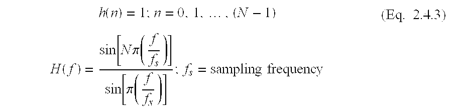
- FIR Finite Impulse Response
- the frequency response curve is of the (the digital equivalent of) “sin-x-by-x” form.
- ⁇ S /N the stop-band attenuation is not that much, as little as 13 dB (approximately) close to the pass band, which is nominally up to 0.5( ⁇ S /N), but improving as the frequency is increased.
- the DMT scheme can introduce a clever mechanism to reduce this perceived impairment.
- the multiplexing and demultiplexing functions are “dual” operations.
- FIG. 8 From a Signal Processing viewpoint, the multiplexing and demultiplexing functions are “dual” operations.
- the configuration of FIG. 8 is referred to as a “maximally decimated filter-bank” because the under-sampling factor (i.e., N) is equal to the number of channels and thus the overall number of samples per second is the same for the set of N sub-channels versus the combined signal.
- the DMT data pump principle is a clever method to overcome the “non-ideal” nature of the implied low-pass filter.
- the principle is based on the following property of the Discrete Fourier Transform (DFT).
- DFT Discrete Fourier Transform
- circular convolution is similar to regular convolution except that the indices are constrained to lie in the range 0 through (N ⁇ 1) using the modulo(N) operation to map integers outside this range into this range.
- the DFTs of the three N-point sequences ⁇ x(n); n 0,1, . . .
- the DFT transforms circular convolution in the “time-domain” to multiplication in the “frequency-domain”.
- the range of the index k encompasses all the non-zero elements of the impulse response ⁇ h C (n) ⁇ which, in general, is an infinite range, from 0 to ⁇ (infinity). Note that even if the range were finite, the convolution is not a circular convolution and thus the transform-domain equivalent, assuming we use the DFT, does not follow Eq. (2.4.5). Recognizing that if ⁇ w(n) ⁇ is periodic, then the regular convolution of Eq. (2.4.6) does indeed reduce to a circular convolution, the approach taken in the DMT data pump is to mimic a periodic behavior.
- cyclic prefix allows us to model the filtering action of the cable as being cyclic convolution, rather than regular convolution. This modeling is appropriate if (and only if) the effective cable impulse response is FIR with an impulse response length less than the size of the cyclic prefix.
- a special equalization procedure is mandated which “equalizes” the cable to the extent that, in conjunction with the equalizer, the effective impulse response is FIR.
- the improved data pump is based on the principle of the Digital Filter Bank used in the Transmultiplexer. Specifically, it calls for improved filters, compared to the DMT scheme, in the configurations depicted in FIG. 7 and FIG. 8 . Furthermore, we show that even though the computational burden for such filters would be greater than the computational burden in the case of the DMT (“Rectangular Window” low-pass filter), the overall computational burden is less and furthermore, the need for increasing the speed of the ADC and DAC by the factor of (N+K — 1)/N is obviated.
- the filter bank principle allows for filter lengths longer than N (the size of the DFT) and thus we can provide for filter characteristics that are superior to that of the N-point rectangular window called out in the DMT standard. Having a better filter characteristic implies that the channel separation is more robust and thus we do not have to resort to the cyclic prefix extension of the DMT.
- the filter bank principle details how a filter of length R ⁇ N can be applied. Details can be found in references [5] through [8]. Simply put, the extended length R ⁇ N can be implemented as N separate R-point FIR filters.
- the mini-FIR filters also referred to as a “weighting network”
- the N R-point filters are positioned after the serial to parallel conversion and before the DFT computation. It can be shown that “R” does not have to be the same for the modulation and demodulation processing but it is usual to have the same length filter for both operations.
- the ratio, R, of the length of the DFT (N) and length of the filter (R ⁇ N), can be referred to as “the number of active taps”.
- FIG. 9 we show how the scheme depicted in FIG. 6 is modified to accommodate the longer filters for channel delineation.
- the filters labeled “H” in the modulator and “G” in the demodulator could be derived from different “prototype” filters but in most cases the same design is used for both operations.
- H and “G” are the same for this discussion.
- the N R-point filters are seen to have impulse responses corresponding to the N different phases whereby the impulse response of the prototype filter can be under-sampled by a factor of N.
- Eq. (3.1.1) we can split the index m which runs from 0 through (RN — 1) into a double index in a manner suggested by Eq.
- FIG. 10 A configuration of an ADSL modem using the improved data pump is depicted in FIG. 10 . Only the frequency division duplexing mode is shown here because we believe that with the line extender unit deployed, the echo-canceling version is not appropriate. However, the improved data pump method can indeed be used in an echo-canceling mode.
- a high pass filter HPF unit is coupled to the D/A units.
- a 2 w-to-4 w converter is coupled to the HPF unit and the 2 w-to-4 w converter is also coupled to a low pass filter LPF unit which is in-turn coupled to the A/D unit.
- An ADSL repeater 1000 is coupled to the 2 W-to-4 w converter.
- the improved data pump can also be called the “Transmux” form since it is based on the theory of the Transmultiplexer).
- the “back-end” processing related to data formatting, error detection and correction, coding, etc., can be the same for both data pumps.
- the distinction between them include the following points.
- DMT uses a cyclic prefix ; the Transmux uses a Weighting Network (of R-point FIR filters).
- DMT uses channel equalization for making the transmission medium appear “FIR”; the Transmux uses a Weighting Network (of R-point FIR filters).
- the DMT scheme to accommodate the cyclic prefix extension uses a line sampling rate which is greater than N-times the symbol-rate (the symbol-rate is 4 kHz for ADSL), while the Transmux scheme uses a line sampling rate of exactly N-times the symbol-rate.
- DMT SOLUTION Split up (wideband) channel into several (narrowband) channels and then:
- TRANSMUX SOLUTION Split up (wideband) channel into several (narrowband) channels and then:
- DMT uses a rectangular window of length N DFT-size. Adjacent channel attenuation as low as 13 dB.
- stopband attenuation is typically 40+ dB.
- DMT assumes wideband channel is FIR. Uses cyclic extension of symbol vector to “fake” cyclic convolution.
- TRANSMUX assumes channel is reasonably flat over adjacent narrowband channels. ICSI eliminated by suitable channel-definition filter design (e.g. raised-cosine)
- DMT requires wideband equalization to force wideband channel to “look FIR”.
- TRANSMUX does not require wide-band equalization.
- DMT requires precision wideband cancellation (adaptive wrt cable makeup)
- TRANSMUX can use multiple cancellers
- the efficacy of using more than one active tap is demonstrated in the following charts which indicate spectral occupancy.
- the DMT scheme frequency characteristic were computed, for the purposes of these charts, by ignoring the cyclic prefix.
- both the Transmux scheme and DMT scheme used a symbol rate of 4 kHz and a line sampling rate of N*4 kHz, i.e., 256 kHz in the upstream direction and 2048 kHz in the downstream direction.
- the DMT scheme corresponds to a “rectangular window” filter or, equivalently, 1 active tap.
- For the Transmux scheme we assumed 3 active taps and used a Hamming frequency characteristic which, while not optimal, is adequate to demonstrate the frequency behavior that can be expected.
- FIG. 11 shows a frequency response of a prototype low-pass filter for an upstream signal.
- FIG. 12 shows an exemplary power spectral density for an upstream signal assuming FDD operation and a highest sub-channel carrier frequency of 84 kHz.
- FIG. 13 illustrates an exemplary power spectral density for a downstream signal assuming FDD and a lowest sub-channel carrier of 200 kHz. The frequency range from 256 kHz to 1024 kHz not shown in FIG. 13 .
- the invention can also utilize data processing methods that transform signals from the digital subscriber loop to actuate interconnected discrete hardware elements. For example, to remotely fine-tune (gain adjustment and/or band-pass adjustment) and/or reconfigure (downstream/upstream reallocation) repeater(s) after initial installation using on network control signals sent over the DSL.
- the invention can also be included in a kit.
- the kit can include some, or all, of the components that compose the invention.
- the kit can be an in-the-field retrofit kit to improve existing systems that are capable of incorporating the invention.
- the kit can include software, firmware and/or hardware for carrying out the invention.
- the kit can also contain instructions for practicing the invention. Unless otherwise specified, the components, software, firmware, hardware and/or instructions of the kit can be the same as those used in the invention.
- the term deploying, as used herein, is defined as designing, building, shipping, installing and/or operating.
- the term means, as used herein, is defined as hardware, firmware and/or software for achieving a result.
- the term program or phrase computer program, as used herein, is defined as a sequence of instructions designed for execution on a computer system.
- a program, or computer program may include a subroutine, a function, a procedure, an object method, an object implementation, an executable application, an applet, a servlet, a source code, an object code, a shared library/dynamic load library and/or other sequence of instructions designed for execution on a computer system.
- the terms including and/or having, as used herein, are defined as comprising (i.e., open language).
- the terms a or an, as used herein, are defined as one or more than one.
- the term another, as used herein, is defined as at least a second or more.
- a practical application of the invention that has value within the technological arts is local digital subscriber loop service. Further, the invention is useful in conjunction with digital subscriber loop networks (such as are used for the purpose of local area networks or metropolitan area networks or wide area networks), or the like. There are virtually innumerable uses for the invention, all of which need not be detailed here.
- a digital subscriber loop repeater representing an embodiment of the invention can be cost effective and advantageous for at least the following reasons.
- the invention permits DSL to be provided on long loops.
- the invention permits DSL to be provided on loaded loops.
- the “Transmux” scheme is superior to the agreed upon standard, called “DMT”, especially in situations where the separation of upstream and downstream traffic is achieved using filters; that is, in the Frequency Division Duplexing (or FDD) mode of operation.
- the new scheme is especially appropriate for providing ADSL over long subscriber loops which require “repeaters” or “extenders”. While conventional DSL installation requires that all load coils be removed from a loop, the invention can include the replacement of these load coils with what can be termed an “ADSL Repeater” or “ADSL Extender”.
- ADSL Repeaters in place of load coils
- one particular form of ADSL that uses the technique of frequency-division-duplexing can be provided to customers over very long loops.
- a variation of the Repeater is the “Mid-Span Extender“ where the unit is not necessarily placed at a load coil site.
- the invention improves quality and/or reduces costs compared to previous approaches.
- the individual components need not be formed in the disclosed shapes, or combined in the disclosed configurations, but could be provided in virtually any shapes, and/or combined in virtually any configuration. Further, the individual components need not be fabricated from the disclosed materials, but could be fabricated from virtually any suitable materials.
Abstract
Description


| Chart 4 DMT versus TRANSMUX |
| Split-Band Operation (ATU-C)* |
| Parameter | DMT | TRANSMUX |
| FFT (N = 512 & | N.log(N) + M.log(M) | N.log(N) + M.log(M) |
| M = 64) | ||
| Cyclic prefix/ | 0 | 3.N + 3.M = 1728 |
| weighting-network | ||
| Time-Domain | 32.M = 2048 | 0 |
| Equalizer | ||
| Analog HPF rejection | X dB | (X-27) dB |
| in 10 to 44 kHz band | ||
| *Operations at the symbol rate (4 kHz) ignoring cyclic prefix in DMT | ||
| |
| Split-band Operation (ATU-R)* |
| Parameter | DMT | TRANSMUX |
| FFT (N = 64 & | N.log(N) + M.log(M) | N.log(N) + M.log(M) |
| M = 512) | ||
| Cyclic prefix/ | 0 | 3.N + 3.M = 1728 |
| weighting-network | ||
| Time-Domain | 32.M = 16384 | 0 |
| Equalizer | ||
| Analog LPF rejection | X dB | (X-27) dB |
| in 20 to 84 kHz band | ||
| *Operations at the symbol rate (4 kHz) ignoring cyclic prefix in DMT | ||
Claims (16)
Priority Applications (4)
| Application Number | Priority Date | Filing Date | Title |
|---|---|---|---|
| US09/821,841 US6507606B2 (en) | 2000-03-29 | 2001-03-28 | Asymmetric digital subscriber line methods suitable for long subscriber loops |
| PCT/US2001/010734 WO2001073954A2 (en) | 2000-03-29 | 2001-03-29 | Asymmetric digital subscriber line methods suitable for long subscriber loops |
| AU2001249806A AU2001249806A1 (en) | 2000-03-29 | 2001-03-29 | Asymmetric digital subscriber line methods suitable for long subscriber loops |
| US10/284,057 US7039103B2 (en) | 2000-03-29 | 2002-10-30 | Asymmetric digital subscriber line methods suitable for long subscriber loops |
Applications Claiming Priority (2)
| Application Number | Priority Date | Filing Date | Title |
|---|---|---|---|
| US19306100P | 2000-03-29 | 2000-03-29 | |
| US09/821,841 US6507606B2 (en) | 2000-03-29 | 2001-03-28 | Asymmetric digital subscriber line methods suitable for long subscriber loops |
Related Child Applications (1)
| Application Number | Title | Priority Date | Filing Date |
|---|---|---|---|
| US10/284,057 Continuation US7039103B2 (en) | 2000-03-29 | 2002-10-30 | Asymmetric digital subscriber line methods suitable for long subscriber loops |
Publications (2)
| Publication Number | Publication Date |
|---|---|
| US20020001340A1 US20020001340A1 (en) | 2002-01-03 |
| US6507606B2 true US6507606B2 (en) | 2003-01-14 |
Family
ID=26888643
Family Applications (2)
| Application Number | Title | Priority Date | Filing Date |
|---|---|---|---|
| US09/821,841 Expired - Fee Related US6507606B2 (en) | 2000-03-29 | 2001-03-28 | Asymmetric digital subscriber line methods suitable for long subscriber loops |
| US10/284,057 Expired - Fee Related US7039103B2 (en) | 2000-03-29 | 2002-10-30 | Asymmetric digital subscriber line methods suitable for long subscriber loops |
Family Applications After (1)
| Application Number | Title | Priority Date | Filing Date |
|---|---|---|---|
| US10/284,057 Expired - Fee Related US7039103B2 (en) | 2000-03-29 | 2002-10-30 | Asymmetric digital subscriber line methods suitable for long subscriber loops |
Country Status (3)
| Country | Link |
|---|---|
| US (2) | US6507606B2 (en) |
| AU (1) | AU2001249806A1 (en) |
| WO (1) | WO2001073954A2 (en) |
Cited By (33)
| Publication number | Priority date | Publication date | Assignee | Title |
|---|---|---|---|---|
| US20020106012A1 (en) * | 2001-02-06 | 2002-08-08 | Norrell Andrew L. | Loop extender with communications, control, and diagnostics |
| US20020106076A1 (en) * | 2001-02-06 | 2002-08-08 | Norrell Andrew L. | Line powered loop extender with communications, control, and diagnostics |
| US20020106072A1 (en) * | 2001-02-06 | 2002-08-08 | Apfel Russell J. | Method and apparatus for improving gain bandwidth paths |
| US20020106013A1 (en) * | 2001-02-06 | 2002-08-08 | Norrell Andrew L. | Loop extender with selectable line termination and equalization |
| US20020110221A1 (en) * | 2001-02-15 | 2002-08-15 | Norrell Andrew L. | System and method for fault isolation for DSL loop extenders |
| US20020141569A1 (en) * | 2001-01-17 | 2002-10-03 | Norrell Andrew L. | DSL compatible load coil |
| US20030045240A1 (en) * | 2000-04-21 | 2003-03-06 | Symmetricom, Inc. | Fault detection for subscriber loop repeaters |
| US20030118090A1 (en) * | 2001-12-20 | 2003-06-26 | Redfern Arthur John | Variable block rate ADSL |
| US20030147359A1 (en) * | 2002-02-07 | 2003-08-07 | Via Technologies, Inc. | Long-distance network transmission structure and associated device |
| US20030169807A1 (en) * | 2002-02-28 | 2003-09-11 | Dietmar Straeussnigg | Method for transmitting an analog data stream with sampling rate increase in the data stream transmitter, and a circuit arrangement for carrying out this method |
| US6728366B1 (en) * | 1999-11-23 | 2004-04-27 | Telefonaktiebolaget Lm Ericsson | Signal level adjustment arrangement |
| US6751315B1 (en) * | 1999-10-18 | 2004-06-15 | Silicon Labs Isolation, Inc. | High bandwidth phone line transceiver with capacitor isolation |
| US20040120470A1 (en) * | 2002-12-23 | 2004-06-24 | Sbc Properties, L.P. | Equivalent working length determinative system for digital subscriber line circuits |
| US20040165614A1 (en) * | 2003-02-24 | 2004-08-26 | Kun-Hak Lee | System for extending distance of x Digital Subscriber Line using reserved telephone line |
| US20050058115A1 (en) * | 1999-08-23 | 2005-03-17 | Levin Howard E. | Method and apparatus for data allocation in an overlapenable communication system |
| US20050163057A1 (en) * | 2004-01-28 | 2005-07-28 | Sbc Knowledge Ventures, L.P. | Digital subscriber line user capacity estimation |
| US20050163166A1 (en) * | 2004-01-28 | 2005-07-28 | Sbc Knowledge Ventures, L.P. | Voice over internet protocol (VoIP) telephone apparatus and communications systems for carrying VoIP traffic |
| US20050163286A1 (en) * | 2004-01-20 | 2005-07-28 | Sbc Knowledge Ventures, L.P. | Automated DSL performance adjustment |
| US20050163128A1 (en) * | 2004-01-28 | 2005-07-28 | Sbc Knowledge Ventures, L.P. | Digital subscriber line user capacity estimation |
| US20050180463A1 (en) * | 2004-02-12 | 2005-08-18 | Sbc Knowledge Ventures, L.P. | Connection management for data networks |
| US20050237940A1 (en) * | 2004-04-21 | 2005-10-27 | Bellsouth Intellectual Property Corporation | Adaptively applying a target noise margin to a DSL loop for DSL data rate establishment |
| US20050243904A1 (en) * | 2004-05-03 | 2005-11-03 | Sbc Knowledge Ventures, L.P. | Method for detecting bridged taps on telephony cable |
| US6977958B1 (en) * | 2000-02-23 | 2005-12-20 | 2Wire, Inc. | Differentially-driven loop extender |
| US20060029207A1 (en) * | 2004-07-12 | 2006-02-09 | Luis Larzabal | Amplifier for unshielded twisted pair wire signals |
| US20060098804A1 (en) * | 2004-07-12 | 2006-05-11 | Phylogy, Inc., A Ca Corporation | High performance ADSL line conditioner system and method |
| US7072385B1 (en) | 2000-02-23 | 2006-07-04 | 2Wire, Inc. | Load coil and DSL repeater including same |
| US20060285496A1 (en) * | 2004-01-28 | 2006-12-21 | Sbc Knowledge Ventures, L.P. | Digital subscriber line user capacity estimation |
| US20070002758A1 (en) * | 2005-06-15 | 2007-01-04 | Blackburn Stuart Lynch | Methods and apparatus to determine digital subscriber line configuration parameters |
| US20070116256A1 (en) * | 2005-10-11 | 2007-05-24 | Phylogy, Inc. A California Corporation | Method and apparatus for powering electronics associated with a telephone line twisted pair |
| US20070140469A1 (en) * | 2004-07-12 | 2007-06-21 | Phylogy, Inc., A California Corporation | Multi-stage differential warping amplifier and method |
| US20070274458A1 (en) * | 2004-01-05 | 2007-11-29 | Sbc Knowledge Ventures, Lp | Automated DSL performance adjustment |
| US20070291794A1 (en) * | 2004-01-20 | 2007-12-20 | Sbc Knowledge Ventures, Lp | System and method to determine broadband transport perfromance data |
| US7346158B1 (en) * | 2002-10-25 | 2008-03-18 | At&T Bls Intellectual Property, Inc. | Method and system for wiring a digital subscriber line circuit |
Families Citing this family (23)
| Publication number | Priority date | Publication date | Assignee | Title |
|---|---|---|---|---|
| US7023910B1 (en) * | 2000-12-21 | 2006-04-04 | 2Wire, Inc. | Dual-line DSL system and method |
| US7006610B2 (en) * | 2001-06-27 | 2006-02-28 | Symmetricom, Inc. | Download booster for ADSL transmission |
| US8149904B2 (en) * | 2002-01-24 | 2012-04-03 | Broadcom Corporation | Asymmetric digital subscriber line modem apparatus and methods therefor |
| US7471777B2 (en) * | 2002-05-08 | 2008-12-30 | Summit Technology Systems, Lp | Indirect DSL over loaded and unloaded loops |
| JP3715282B2 (en) * | 2002-06-20 | 2005-11-09 | 松下電器産業株式会社 | OFDM receiver and OFDM signal correction method |
| JP3986929B2 (en) * | 2002-08-27 | 2007-10-03 | 富士通株式会社 | Leakage electromagnetic field suppression transmission method and leakage electromagnetic field suppression transmission apparatus in power line carrier communication |
| DE102004043187A1 (en) * | 2004-09-07 | 2006-03-09 | Deutsche Telekom Ag | Digital subscriber line connection method, involves making available digital subscriber line upward channel and downward channel, and amplifying upper frequency range of downward channel using amplifier |
| WO2006042274A1 (en) * | 2004-10-11 | 2006-04-20 | 2Wire, Inc. | Periodic impulse noise mitigation in a dsl system |
| US7953163B2 (en) * | 2004-11-30 | 2011-05-31 | Broadcom Corporation | Block linear equalization in a multicarrier communication system |
| US7852950B2 (en) * | 2005-02-25 | 2010-12-14 | Broadcom Corporation | Methods and apparatuses for canceling correlated noise in a multi-carrier communication system |
| US9374257B2 (en) * | 2005-03-18 | 2016-06-21 | Broadcom Corporation | Methods and apparatuses of measuring impulse noise parameters in multi-carrier communication systems |
| US20060291500A1 (en) * | 2005-06-03 | 2006-12-28 | Adc Dsl Systems, Inc. | Non-intrusive transmit adjustment control |
| US7668230B2 (en) * | 2005-06-03 | 2010-02-23 | Adc Dsl Systems, Inc. | Non-intrusive digital subscriber line transmit adjustment method |
| SE529049C2 (en) * | 2005-07-18 | 2007-04-17 | Macab Ab | Data communication device and method for converting baseband data signals for transmission via coaxial cable |
| US7813439B2 (en) * | 2006-02-06 | 2010-10-12 | Broadcom Corporation | Various methods and apparatuses for impulse noise detection |
| TWI379201B (en) * | 2008-05-27 | 2012-12-11 | Novatek Microelectronics Corp | Data description method and related packet and testing system for a serial transmission interface |
| US8605837B2 (en) | 2008-10-10 | 2013-12-10 | Broadcom Corporation | Adaptive frequency-domain reference noise canceller for multicarrier communications systems |
| JP5540224B2 (en) * | 2009-07-17 | 2014-07-02 | エタニ電機株式会社 | Impulse response measuring method and impulse response measuring apparatus |
| US8499021B2 (en) | 2010-08-25 | 2013-07-30 | Qualcomm Incorporated | Circuit and method for computing circular convolution in streaming mode |
| KR102244612B1 (en) * | 2014-04-21 | 2021-04-26 | 삼성전자주식회사 | Appratus and method for transmitting and receiving voice data in wireless communication system |
| WO2017084705A1 (en) * | 2015-11-18 | 2017-05-26 | Fraunhofer-Gesellschaft zur Förderung der angewandten Forschung e.V. | Signal processing systems and signal processing methods |
| WO2018004538A2 (en) * | 2016-06-28 | 2018-01-04 | Borgwarner Inc. | Solenoid having inverse tapered armature for solenoid-actuated valve |
| CN112838994B (en) | 2019-11-22 | 2024-03-19 | 中兴通讯股份有限公司 | Link pre-equalization compensation method and device, storage medium and electronic device |
Citations (24)
| Publication number | Priority date | Publication date | Assignee | Title |
|---|---|---|---|---|
| US3843844A (en) | 1971-06-04 | 1974-10-22 | Int Standard Electric Corp | Subscriber loop circuit apparatus |
| US4037066A (en) * | 1975-03-20 | 1977-07-19 | Lorain Products Corporation | Repeater for transmission lines |
| US4131766A (en) | 1977-07-11 | 1978-12-26 | Granger Associates | Digital filter bank |
| US4237551A (en) | 1978-12-22 | 1980-12-02 | Granger Associates | Transmultiplexer |
| US4277655A (en) * | 1978-10-16 | 1981-07-07 | Lear Siegler, Inc. | Automatic gain repeater |
| US4323733A (en) * | 1980-11-28 | 1982-04-06 | Bell Telephone Laboratories, Inc. | Range extender with variable gain for coin telephone loops |
| US5095528A (en) | 1988-10-28 | 1992-03-10 | Orion Industries, Inc. | Repeater with feedback oscillation control |
| WO1995017046A1 (en) | 1993-12-17 | 1995-06-22 | Bell Communications Research, Inc. | An improved discrete multitone echo canceler |
| US5610922A (en) * | 1995-03-20 | 1997-03-11 | Raychem Corporation | Voice plus 4-wire DDS multiplexer |
| US5627501A (en) | 1994-04-14 | 1997-05-06 | Alcatel N.V. | Signal coupler with automatic common line attenuation compensation |
| US5691718A (en) * | 1995-06-07 | 1997-11-25 | Raychem Corporation | Dual 4-wire analog data multiplexer |
| EP0853390A2 (en) | 1997-01-08 | 1998-07-15 | Analog Devices, Inc. | Echo canceller for an asymmetric digital subscriber loop modem |
| US5790174A (en) | 1991-09-27 | 1998-08-04 | Bell Atlantic Network Services, Inc. | PSTN architecture for video-on-demand services |
| US5883941A (en) | 1996-11-08 | 1999-03-16 | Godigital Telecommunications | HDSL and POTS carrier system |
| KR19990065094A (en) | 1998-01-07 | 1999-08-05 | 윤종용 | Automatic Gain Control System in High Speed Digital Subscriber Line System |
| US5956323A (en) | 1997-07-30 | 1999-09-21 | Nokia High Speed Access Products Inc. | Power conservation for pots and modulated data transmission |
| US5982785A (en) | 1996-04-23 | 1999-11-09 | Siemens Aktiengesellschaft | Combination conventional telephony and high-bit-rate digital channel transmission system comprising high pass filters which comprise both first order and second order high pass filters |
| GB2337380A (en) | 1998-05-11 | 1999-11-17 | Samsung Electronics Co Ltd | A high speed digital line receiver with a programmable gain amplifier and narrow band noise remover |
| US6029048A (en) | 1997-02-28 | 2000-02-22 | Treatch; James E. | Repeater system having reduced power loss |
| US6092122A (en) * | 1997-06-30 | 2000-07-18 | Integrated Telecom Express | xDSL DMT modem using sub-channel selection to achieve scaleable data rate based on available signal processing resources |
| US6118766A (en) | 1996-08-21 | 2000-09-12 | Godigital Networks Corporation | Multiple ISDN carrier system |
| US6130882A (en) | 1997-09-25 | 2000-10-10 | Motorola, Inc. | Method and apparatus for configuring a communication system |
| US6141330A (en) | 1996-09-20 | 2000-10-31 | Godigital Networks Corporation | Multiple ISDN and pots carrier system |
| US6236664B1 (en) * | 1999-06-04 | 2001-05-22 | Terayon Communications Systems, Inc. | Pair gain system with an ADSL repeater unit |
Family Cites Families (1)
| Publication number | Priority date | Publication date | Assignee | Title |
|---|---|---|---|---|
| US4843844A (en) * | 1982-03-29 | 1989-07-04 | Foster-Boyd, Inc. | Anti-friction two-ply athletic sock |
-
2001
- 2001-03-28 US US09/821,841 patent/US6507606B2/en not_active Expired - Fee Related
- 2001-03-29 WO PCT/US2001/010734 patent/WO2001073954A2/en active Search and Examination
- 2001-03-29 AU AU2001249806A patent/AU2001249806A1/en not_active Abandoned
-
2002
- 2002-10-30 US US10/284,057 patent/US7039103B2/en not_active Expired - Fee Related
Patent Citations (24)
| Publication number | Priority date | Publication date | Assignee | Title |
|---|---|---|---|---|
| US3843844A (en) | 1971-06-04 | 1974-10-22 | Int Standard Electric Corp | Subscriber loop circuit apparatus |
| US4037066A (en) * | 1975-03-20 | 1977-07-19 | Lorain Products Corporation | Repeater for transmission lines |
| US4131766A (en) | 1977-07-11 | 1978-12-26 | Granger Associates | Digital filter bank |
| US4277655A (en) * | 1978-10-16 | 1981-07-07 | Lear Siegler, Inc. | Automatic gain repeater |
| US4237551A (en) | 1978-12-22 | 1980-12-02 | Granger Associates | Transmultiplexer |
| US4323733A (en) * | 1980-11-28 | 1982-04-06 | Bell Telephone Laboratories, Inc. | Range extender with variable gain for coin telephone loops |
| US5095528A (en) | 1988-10-28 | 1992-03-10 | Orion Industries, Inc. | Repeater with feedback oscillation control |
| US5790174A (en) | 1991-09-27 | 1998-08-04 | Bell Atlantic Network Services, Inc. | PSTN architecture for video-on-demand services |
| WO1995017046A1 (en) | 1993-12-17 | 1995-06-22 | Bell Communications Research, Inc. | An improved discrete multitone echo canceler |
| US5627501A (en) | 1994-04-14 | 1997-05-06 | Alcatel N.V. | Signal coupler with automatic common line attenuation compensation |
| US5610922A (en) * | 1995-03-20 | 1997-03-11 | Raychem Corporation | Voice plus 4-wire DDS multiplexer |
| US5691718A (en) * | 1995-06-07 | 1997-11-25 | Raychem Corporation | Dual 4-wire analog data multiplexer |
| US5982785A (en) | 1996-04-23 | 1999-11-09 | Siemens Aktiengesellschaft | Combination conventional telephony and high-bit-rate digital channel transmission system comprising high pass filters which comprise both first order and second order high pass filters |
| US6118766A (en) | 1996-08-21 | 2000-09-12 | Godigital Networks Corporation | Multiple ISDN carrier system |
| US6141330A (en) | 1996-09-20 | 2000-10-31 | Godigital Networks Corporation | Multiple ISDN and pots carrier system |
| US5883941A (en) | 1996-11-08 | 1999-03-16 | Godigital Telecommunications | HDSL and POTS carrier system |
| EP0853390A2 (en) | 1997-01-08 | 1998-07-15 | Analog Devices, Inc. | Echo canceller for an asymmetric digital subscriber loop modem |
| US6029048A (en) | 1997-02-28 | 2000-02-22 | Treatch; James E. | Repeater system having reduced power loss |
| US6092122A (en) * | 1997-06-30 | 2000-07-18 | Integrated Telecom Express | xDSL DMT modem using sub-channel selection to achieve scaleable data rate based on available signal processing resources |
| US5956323A (en) | 1997-07-30 | 1999-09-21 | Nokia High Speed Access Products Inc. | Power conservation for pots and modulated data transmission |
| US6130882A (en) | 1997-09-25 | 2000-10-10 | Motorola, Inc. | Method and apparatus for configuring a communication system |
| KR19990065094A (en) | 1998-01-07 | 1999-08-05 | 윤종용 | Automatic Gain Control System in High Speed Digital Subscriber Line System |
| GB2337380A (en) | 1998-05-11 | 1999-11-17 | Samsung Electronics Co Ltd | A high speed digital line receiver with a programmable gain amplifier and narrow band noise remover |
| US6236664B1 (en) * | 1999-06-04 | 2001-05-22 | Terayon Communications Systems, Inc. | Pair gain system with an ADSL repeater unit |
Non-Patent Citations (30)
| Title |
|---|
| "2Wire delivers HomePortal residential Gateway to consumers for ultra-fast internet access and easy home networking," Business Wire article as it appears on the FindArticles web site at: www.findarticles.com, Oct. 10, 2000. |
| "2Wire Inc. (2W HomePortal)," America's Network article as it appears on the FindArticles web site at: www.findarticles.com, Jun. 1, 2000. |
| "Analog front end for ADSL extends linearity and local-loop length," Article from the END magazine web site at: www.ednmag.com, Jan. 21, 1999. |
| "Chester Telephone doubles the serving distance of its DSL services using Symmetricom's GoLong loop extender; field trials to begin in Chester, S.C. mid-Dec. 2000," Business Wire article as it appears on the FindArticles web site at: www.findarticles.com, Dec. 4, 2000. |
| "Communications companies stay ahead of the curve," Article from the NetWorkFusion web site at: www.nwfusion.com, Dec. 18, 2000. |
| "DSL is coming! DSL is coming!," Article from the Teleconnect web site at: www.teleconnect.com, Sep. 5, 2000. |
| "GDSL: GTE selects GoDigital's GDSL-8 access system: GDSL-8 system quickly meets the demand for GTE's added line growth," EDGE article as it appears on the FindArticles web site at: www.findarticles.com, Sep. 28, 1999. |
| "GDSL-8: GoDigital Telecomminications, Inc. introduces four line drop flexibility with its GDSL-8 digital replacement system for analog carrier, meeting increased local loop line demand and internet access speeds. (Product Announcement)," EDGE article as it appears on the FindArticles web site at: www.findarticles.com, Feb. 8, 1999. |
| "General bandwidth and 2Wire partner to deliver VoDSL solution for the residential market," Cambridge Telecom Report article as it appears on the FindArticles web site at: www.findarticles.com, Jun. 5, 2000. |
| "GoDigital networks adds extended range drops to serve hard-to-reach subscribers," PR Newswire article as it appears on the FindArticles web site at: www.findarticles.com, Jan. 18, 2000. |
| "GoDigital Networks first to introduce line-powered solution for delivering both voice and DSL to any location," PR Newswire article as it appears on the FindArticles web site at: www.findarticles.com, Jun. 6, 2000. |
| "GoDigital Networks Increases reliability of DSL services and extends reach to 25 miles from central office," PR Newswire article as it appears on the FindArticles web site at: www.findarticles.com, Oct. 13, 1999. |
| "GoDigital Telecomminications, Inc. introduces long loop high speed internet access support with its GDSL BRI-3 product line," Business Wire article as it appears on the FindArticles web site at: www.findarticles.com, Mar. 22, 1999. |
| "HomePortal(TM) 1000: Bringing the power of DSL Home," 2 Wire, Inc. brochure, 1999. |
| "HomePortal™ 1000: Bringing the power of DSL Home," 2 Wire, Inc. brochure, 1999. |
| "Independent laboratory testing confirms that Symmetricom's GoLong doubles the reach of ADSL services," Business Wirearticle as it appears on the FindArticles web site at: www.findarticles.com, Nov. 7, 2000. |
| "Intranets and I-commerce-hotlinks (news briefs)," InfoWorld article as it appears on the FindArticles web site at: www.findarticles.com, Mar. 6, 2000. |
| "Microfilter design promises peaceful coexistence between ADSL and the voiceband. (Technology Information)," EDN article as it appears on the FindArticles web site at: www.findarticles.com, Dec. 9, 1999. |
| "Microfilter design promises peaceful coexistence between ADSL and the voiceband. (Technology Information)," EDN magazine article as it appears on the FindArticles web site at: www.findarticles.com, Dec. 9, 1999. |
| "Office Depot and 2Wire announce strategic retail partnership for leading residential Gateway products," EDGE: Work-Group Computing Report article as it appears on the FindArticles web site at: www.findarticles.com, Jun. 5, 2000. |
| "Symmetricom replaces headline in Chester Telephone release; Symmetricom's Go-Long loop extender doubles the serving distance of Chester Telephone's DSL services," Business Wire article as it appears on the FindArticles web site at : www.findarticles.com, Dec. 4, 2000. |
| "Symmetricom's Go-Long loop extender doubles the serving distance of Chester Telephone'DSL services; field trials to begin in Chester, S.C. mid-Dec. 2000," Business Wire article as it appears on the FindArticles web site at: findarticles.com, Dec. 4, 2000. |
| "Symmetricom's new GoLong solution doubles current reach of ADSL, enabling ADSL everywhere," Business Wire article as it appears on the FindArticles web site at: www.findarticles.com, Jun. 7, 2000. |
| "The 39 (Network) Steps. (News Briefs)," Home Office Computing article as it appears on the FindArticles web site at: www.findarticles.com, Aug. 2000. |
| "The fastest towns in America (Technology Information)," Home Office Computing article as it appears on the FindArticles web site at: www.findarticles.com, Apr. 2000. |
| "The next big home networking thing, (Technology Information)," Home Office Computing article as it appears on the FindArticles web site at: www.findarticles.com, Mar. 2000. |
| "TriMedia boxes ready soon," Electronics Times article as it appears on the FindArticles web site at: www.findarticles.com, Sep. 18, 2000. |
| International Search Report dated Oct. 10, 2001. |
| Jones, "Frequency domain echo cancellation for discrete multitone asymmetric digital subscriber line transceivers," IEEE Transactions on Cummunications, 43(2):1663-1672, 1995. |
| Wang et al., "Automatic gain control VLSI architecture foe ADSL-1 cap system," Journal of the Chinese Institute of Electrical Engineering., pp 261-268, 1995. |
Cited By (62)
| Publication number | Priority date | Publication date | Assignee | Title |
|---|---|---|---|---|
| US7830855B2 (en) | 1999-08-23 | 2010-11-09 | Freescale Semiconductor, Inc. | Method and apparatus for data allocation in an overlap-enabled communication system |
| US20050058115A1 (en) * | 1999-08-23 | 2005-03-17 | Levin Howard E. | Method and apparatus for data allocation in an overlapenable communication system |
| US6751315B1 (en) * | 1999-10-18 | 2004-06-15 | Silicon Labs Isolation, Inc. | High bandwidth phone line transceiver with capacitor isolation |
| US6728366B1 (en) * | 1999-11-23 | 2004-04-27 | Telefonaktiebolaget Lm Ericsson | Signal level adjustment arrangement |
| US6977958B1 (en) * | 2000-02-23 | 2005-12-20 | 2Wire, Inc. | Differentially-driven loop extender |
| US7072385B1 (en) | 2000-02-23 | 2006-07-04 | 2Wire, Inc. | Load coil and DSL repeater including same |
| US6842426B2 (en) * | 2000-04-21 | 2005-01-11 | Symmetricom, Inc. | Fault detection for subscriber loop repeaters |
| US20030045240A1 (en) * | 2000-04-21 | 2003-03-06 | Symmetricom, Inc. | Fault detection for subscriber loop repeaters |
| US20020141569A1 (en) * | 2001-01-17 | 2002-10-03 | Norrell Andrew L. | DSL compatible load coil |
| US6947529B2 (en) * | 2001-01-17 | 2005-09-20 | 2Wire, Inc. | DSL compatible load coil |
| US20020106012A1 (en) * | 2001-02-06 | 2002-08-08 | Norrell Andrew L. | Loop extender with communications, control, and diagnostics |
| US20020106072A1 (en) * | 2001-02-06 | 2002-08-08 | Apfel Russell J. | Method and apparatus for improving gain bandwidth paths |
| US7190716B2 (en) * | 2001-02-06 | 2007-03-13 | 2Wire, Inc | Line powered loop extender with communications, control, and diagnostics |
| US20020106013A1 (en) * | 2001-02-06 | 2002-08-08 | Norrell Andrew L. | Loop extender with selectable line termination and equalization |
| US20020106076A1 (en) * | 2001-02-06 | 2002-08-08 | Norrell Andrew L. | Line powered loop extender with communications, control, and diagnostics |
| US7194023B2 (en) | 2001-02-06 | 2007-03-20 | 2Wire, Inc. | Loop extender with communications, control, and diagnostics |
| US7483528B2 (en) * | 2001-02-06 | 2009-01-27 | 2Wire, Inc. | Loop extender with selectable line termination and equalization |
| US20020110221A1 (en) * | 2001-02-15 | 2002-08-15 | Norrell Andrew L. | System and method for fault isolation for DSL loop extenders |
| US7061857B2 (en) | 2001-02-15 | 2006-06-13 | 2Wire, Inc. | System and method for fault isolation for DSL loop extenders |
| US7333535B2 (en) * | 2001-12-20 | 2008-02-19 | Texas Instruments Incorporated | Variable block rate ADSL |
| US20030118090A1 (en) * | 2001-12-20 | 2003-06-26 | Redfern Arthur John | Variable block rate ADSL |
| US20030147359A1 (en) * | 2002-02-07 | 2003-08-07 | Via Technologies, Inc. | Long-distance network transmission structure and associated device |
| US20030169807A1 (en) * | 2002-02-28 | 2003-09-11 | Dietmar Straeussnigg | Method for transmitting an analog data stream with sampling rate increase in the data stream transmitter, and a circuit arrangement for carrying out this method |
| US7346158B1 (en) * | 2002-10-25 | 2008-03-18 | At&T Bls Intellectual Property, Inc. | Method and system for wiring a digital subscriber line circuit |
| US7620154B2 (en) | 2002-12-23 | 2009-11-17 | Cambron G Keith | Equivalent working length determinative system for digital subscriber line circuits |
| US20040120470A1 (en) * | 2002-12-23 | 2004-06-24 | Sbc Properties, L.P. | Equivalent working length determinative system for digital subscriber line circuits |
| US20040165614A1 (en) * | 2003-02-24 | 2004-08-26 | Kun-Hak Lee | System for extending distance of x Digital Subscriber Line using reserved telephone line |
| US7920677B2 (en) | 2004-01-05 | 2011-04-05 | At&T Intellectual Property I, L.P. | Automated DSL performance adjustment |
| US20070274458A1 (en) * | 2004-01-05 | 2007-11-29 | Sbc Knowledge Ventures, Lp | Automated DSL performance adjustment |
| US20110142206A1 (en) * | 2004-01-20 | 2011-06-16 | At&T Intellectual Property I,L.P. | Automated DSL Performance Adjustment |
| US7362713B2 (en) | 2004-01-20 | 2008-04-22 | Sbc Knowledge Ventures, Lp. | System and method for accessing digital subscriber line data |
| US8670525B2 (en) | 2004-01-20 | 2014-03-11 | At&T Intellectual Property I, L.P. | Automated DSL performance adjustment |
| US8451978B2 (en) | 2004-01-20 | 2013-05-28 | At&T Intellectual Property I, L.P. | Automated DSL performance adjustment |
| US20070291794A1 (en) * | 2004-01-20 | 2007-12-20 | Sbc Knowledge Ventures, Lp | System and method to determine broadband transport perfromance data |
| US20050163286A1 (en) * | 2004-01-20 | 2005-07-28 | Sbc Knowledge Ventures, L.P. | Automated DSL performance adjustment |
| US7272209B2 (en) | 2004-01-20 | 2007-09-18 | Sbc Knowledge Ventures, L.P. | Automated DSL performance adjustment |
| US7920480B2 (en) | 2004-01-20 | 2011-04-05 | At&T Intellectual Property I, L.P. | System and method to determine broadband transport performance data |
| US7126914B2 (en) | 2004-01-28 | 2006-10-24 | Sbc Knowledge Ventures, Lp | Digital subscriber line user capacity estimation |
| US20050163128A1 (en) * | 2004-01-28 | 2005-07-28 | Sbc Knowledge Ventures, L.P. | Digital subscriber line user capacity estimation |
| US20050163057A1 (en) * | 2004-01-28 | 2005-07-28 | Sbc Knowledge Ventures, L.P. | Digital subscriber line user capacity estimation |
| US20050163166A1 (en) * | 2004-01-28 | 2005-07-28 | Sbc Knowledge Ventures, L.P. | Voice over internet protocol (VoIP) telephone apparatus and communications systems for carrying VoIP traffic |
| US20060285496A1 (en) * | 2004-01-28 | 2006-12-21 | Sbc Knowledge Ventures, L.P. | Digital subscriber line user capacity estimation |
| US7342920B2 (en) | 2004-01-28 | 2008-03-11 | Sbc Knowledge Ventures, L.P. | Voice over internet protocol (VoIP) telephone apparatus and communications systems for carrying VoIP traffic |
| US7123584B2 (en) | 2004-01-28 | 2006-10-17 | Sbc Knowledge Ventures, L.P. | Digital subscriber line user capacity estimation |
| US7808978B2 (en) | 2004-01-28 | 2010-10-05 | At&T Intellectual Property I, L.P. | Voice over internet protocol (VoIP) telephone apparatus and communication system for carrying VoIP traffic |
| US20080130633A1 (en) * | 2004-01-28 | 2008-06-05 | Sbc Knowledge Ventures, L.P. | Voice Over Internet Protocol (VOIP) Telephone Apparatus and Communication System for Carrying VOIP Traffic |
| US20050180463A1 (en) * | 2004-02-12 | 2005-08-18 | Sbc Knowledge Ventures, L.P. | Connection management for data networks |
| US7876775B2 (en) | 2004-02-12 | 2011-01-25 | At&T Intellectual Property I, L.P. | Connection management for data networks |
| US20050237940A1 (en) * | 2004-04-21 | 2005-10-27 | Bellsouth Intellectual Property Corporation | Adaptively applying a target noise margin to a DSL loop for DSL data rate establishment |
| US7570599B2 (en) | 2004-04-21 | 2009-08-04 | At&T Intellectual Property I, Llp. | Adaptively applying a target noise margin to a digital subscriber line (DSL) loop for DSL data rate establishment |
| US7388906B2 (en) | 2004-05-03 | 2008-06-17 | Sbc Knowledge Ventures, L.P. | Method for detecting bridged taps on telephony cable |
| US20050243904A1 (en) * | 2004-05-03 | 2005-11-03 | Sbc Knowledge Ventures, L.P. | Method for detecting bridged taps on telephony cable |
| US7110528B2 (en) * | 2004-07-12 | 2006-09-19 | Phylogy, Inc. | Amplifier for unshielded twisted pair wire signals |
| US20060029207A1 (en) * | 2004-07-12 | 2006-02-09 | Luis Larzabal | Amplifier for unshielded twisted pair wire signals |
| US20060098804A1 (en) * | 2004-07-12 | 2006-05-11 | Phylogy, Inc., A Ca Corporation | High performance ADSL line conditioner system and method |
| US20070140469A1 (en) * | 2004-07-12 | 2007-06-21 | Phylogy, Inc., A California Corporation | Multi-stage differential warping amplifier and method |
| US8160237B2 (en) | 2004-07-12 | 2012-04-17 | Actelis Networks, Inc. | Multi-stage differential warping amplifier and method |
| US7889671B2 (en) | 2005-06-15 | 2011-02-15 | At&T Intellectual Property I, L.P. | Methods and apparatus to determine digital subscriber line configuration parameters |
| US7558213B2 (en) | 2005-06-15 | 2009-07-07 | AT&T Intellectual Property I, LLP | Methods and apparatus to determine digital subscriber line configuration parameters |
| US20070002758A1 (en) * | 2005-06-15 | 2007-01-04 | Blackburn Stuart Lynch | Methods and apparatus to determine digital subscriber line configuration parameters |
| US7706526B2 (en) | 2005-10-11 | 2010-04-27 | Phylogy, Inc. | Method and apparatus for powering electronics associated with a telephone line twisted pair |
| US20070116256A1 (en) * | 2005-10-11 | 2007-05-24 | Phylogy, Inc. A California Corporation | Method and apparatus for powering electronics associated with a telephone line twisted pair |
Also Published As
| Publication number | Publication date |
|---|---|
| AU2001249806A1 (en) | 2001-10-08 |
| US7039103B2 (en) | 2006-05-02 |
| US20020001340A1 (en) | 2002-01-03 |
| US20030063660A1 (en) | 2003-04-03 |
| WO2001073954A2 (en) | 2001-10-04 |
| WO2001073954A3 (en) | 2002-01-03 |
Similar Documents
| Publication | Publication Date | Title |
|---|---|---|
| US6507606B2 (en) | Asymmetric digital subscriber line methods suitable for long subscriber loops | |
| US7142619B2 (en) | Long subscriber loops using automatic gain control mid-span extender unit | |
| US7394752B2 (en) | Joint reduction of NEXT and FEXT in xDSL systems | |
| US6404806B1 (en) | Method and apparatus for time-domain equalization in FDM-based discrete multi-tone modems | |
| US6842426B2 (en) | Fault detection for subscriber loop repeaters | |
| US20040218756A1 (en) | ISDN crosstalk cancellation in a DSL system | |
| CN101019333A (en) | Interference cancellation system | |
| US7289554B2 (en) | Method and apparatus for channel equalization and cyclostationary interference rejection for ADSL-DMT modems | |
| US6829292B1 (en) | Increasing gain with isolating upstream and downstream filters and amplifiers | |
| US7280469B2 (en) | Efficient implementation of large size FFT | |
| WO1995017046A1 (en) | An improved discrete multitone echo canceler | |
| US7313130B2 (en) | Spectrally compatible mask for enhanced upstream data rates in DSL systems | |
| Vaidyanathan et al. | Discrete multitone modulation with principal component filter banks | |
| US7006610B2 (en) | Download booster for ADSL transmission | |
| US20020061058A1 (en) | Subscriber loop repeater loopback for fault isolation | |
| US8923454B2 (en) | Method, apparatus and system for eliminating aliasing noise in multi-carrier modulation system | |
| US20020113649A1 (en) | Long subscriber loops using modified load coils | |
| US7796685B2 (en) | Systems and methods for minimum-power leakage windowing for VDSL using least square technique | |
| Cruz-Roldán et al. | Design of multi-channel near-perfect-reconstruction transmultiplexers using cosine-modulated filter banks | |
| US20020031216A1 (en) | Subscriber loop range extension using negative-impedance repeaters | |
| Trautmann et al. | Using modulated filter banks for ISI/ICI-corrupted multicarrier transmission | |
| Cornil | Building an ADSL modem, the basics | |
| Ramírez-Mireles et al. | The Benefits of Discrete Multi-Tone (DMT) Modulation for VDSL Systems | |
| Moonen et al. | Electrical Echo Cancellation1 | |
| Ramírez-Mireles et al. | The Benefits Of Discrete Multi-Tone Modulation For VDSL Systems, Part II |
Legal Events
| Date | Code | Title | Description |
|---|---|---|---|
| AS | Assignment |
Owner name: SYMMETRICOM, INC., CALIFORNIA Free format text: ASSIGNMENT OF ASSIGNORS INTEREST;ASSIGNORS:SHENOI, KISHAN;SQUADRITO, SANDRO;BOGARDUS, GARY;REEL/FRAME:011962/0551;SIGNING DATES FROM 20010529 TO 20010530 |
|
| FEPP | Fee payment procedure |
Free format text: PAYOR NUMBER ASSIGNED (ORIGINAL EVENT CODE: ASPN); ENTITY STATUS OF PATENT OWNER: LARGE ENTITY |
|
| FEPP | Fee payment procedure |
Free format text: PAYOR NUMBER ASSIGNED (ORIGINAL EVENT CODE: ASPN); ENTITY STATUS OF PATENT OWNER: LARGE ENTITY Free format text: PAYER NUMBER DE-ASSIGNED (ORIGINAL EVENT CODE: RMPN); ENTITY STATUS OF PATENT OWNER: LARGE ENTITY |
|
| FPAY | Fee payment |
Year of fee payment: 4 |
|
| FPAY | Fee payment |
Year of fee payment: 8 |
|
| AS | Assignment |
Owner name: MICROSEMI FREQUENCY AND TIME CORPORATION, CALIFORN Free format text: CHANGE OF NAME;ASSIGNOR:SYMMETRICOM, INC.;REEL/FRAME:032379/0201 Effective date: 20131203 |
|
| REMI | Maintenance fee reminder mailed | ||
| LAPS | Lapse for failure to pay maintenance fees | ||
| STCH | Information on status: patent discontinuation |
Free format text: PATENT EXPIRED DUE TO NONPAYMENT OF MAINTENANCE FEES UNDER 37 CFR 1.362 |
|
| FP | Lapsed due to failure to pay maintenance fee |
Effective date: 20150114 |
|
| AS | Assignment |
Owner name: MICROSEMI SOC CORP., A CALIFORNIA CORPORATION, CAL Free format text: RELEASE BY SECURED PARTY;ASSIGNOR:BANK OF AMERICA, N.A.;REEL/FRAME:037558/0711 Effective date: 20160115 Owner name: MICROSEMI CORP.-ANALOG MIXED SIGNAL GROUP, A DELAW Free format text: RELEASE BY SECURED PARTY;ASSIGNOR:BANK OF AMERICA, N.A.;REEL/FRAME:037558/0711 Effective date: 20160115 Owner name: MICROSEMI FREQUENCY AND TIME CORPORATION, A DELAWA Free format text: RELEASE BY SECURED PARTY;ASSIGNOR:BANK OF AMERICA, N.A.;REEL/FRAME:037558/0711 Effective date: 20160115 Owner name: MICROSEMI SEMICONDUCTOR (U.S.) INC., A DELAWARE CO Free format text: RELEASE BY SECURED PARTY;ASSIGNOR:BANK OF AMERICA, N.A.;REEL/FRAME:037558/0711 Effective date: 20160115 Owner name: MICROSEMI CORPORATION, CALIFORNIA Free format text: RELEASE BY SECURED PARTY;ASSIGNOR:BANK OF AMERICA, N.A.;REEL/FRAME:037558/0711 Effective date: 20160115 Owner name: MICROSEMI CORP.-MEMORY AND STORAGE SOLUTIONS (F/K/ Free format text: RELEASE BY SECURED PARTY;ASSIGNOR:BANK OF AMERICA, N.A.;REEL/FRAME:037558/0711 Effective date: 20160115 Owner name: MICROSEMI COMMUNICATIONS, INC. (F/K/A VITESSE SEMI Free format text: RELEASE BY SECURED PARTY;ASSIGNOR:BANK OF AMERICA, N.A.;REEL/FRAME:037558/0711 Effective date: 20160115 |