US6452496B1 - Radio frequency identification devices and a method of determining a communication range - Google Patents
Radio frequency identification devices and a method of determining a communication range Download PDFInfo
- Publication number
- US6452496B1 US6452496B1 US09/640,477 US64047700A US6452496B1 US 6452496 B1 US6452496 B1 US 6452496B1 US 64047700 A US64047700 A US 64047700A US 6452496 B1 US6452496 B1 US 6452496B1
- Authority
- US
- United States
- Prior art keywords
- circuitry
- communication
- remote communication
- radio frequency
- frequency identification
- Prior art date
- Legal status (The legal status is an assumption and is not a legal conclusion. Google has not performed a legal analysis and makes no representation as to the accuracy of the status listed.)
- Expired - Lifetime
Links
Images


Classifications
-
- G—PHYSICS
- G08—SIGNALLING
- G08B—SIGNALLING OR CALLING SYSTEMS; ORDER TELEGRAPHS; ALARM SYSTEMS
- G08B21/00—Alarms responsive to a single specified undesired or abnormal condition and not otherwise provided for
- G08B21/02—Alarms for ensuring the safety of persons
- G08B21/0202—Child monitoring systems using a transmitter-receiver system carried by the parent and the child
- G08B21/0222—Message structure or message content, e.g. message protocol
-
- G—PHYSICS
- G08—SIGNALLING
- G08B—SIGNALLING OR CALLING SYSTEMS; ORDER TELEGRAPHS; ALARM SYSTEMS
- G08B21/00—Alarms responsive to a single specified undesired or abnormal condition and not otherwise provided for
- G08B21/02—Alarms for ensuring the safety of persons
- G08B21/0202—Child monitoring systems using a transmitter-receiver system carried by the parent and the child
- G08B21/0227—System arrangements with a plurality of child units
Definitions
- This invention relates to radio frequency identification devices, wireless communication systems, communication methods, methods of forming a radio frequency identification device, methods of testing wireless communication operations, and methods of determining a communication range.
- Wireless communication systems including electronic identification devices, such as radio frequency identification devices (RFIDs), are known in the art. Such devices are typically used for inventory tracking. As large numbers of objects are moved in inventory, product manufacturing, and merchandising operations, there is a continuous challenge to accurately monitor the location and flow of objects. Additionally, there is a continuing goal to determine the location of objects in an inexpensive and streamlined manner.
- RFIDs radio frequency identification devices
- One presently available electronic identification system utilizes a magnetic coupling system.
- the devices are entirely passive (have no power supply), which results in a small and portable package.
- identification systems are only capable of operation over a relatively short range, limited by the size of a magnetic field used to supply power to the devices and to communicate with the devices.
- These systems include integrated circuit devices which include an active transponder and are intended to be affixed to an object to be monitored.
- the devices are capable of receiving and processing instructions transmitted by an interrogator.
- a device receives the instruction, if within range, then processes the instruction and transmits a response, if appropriate.
- the interrogation signal and the responsive signal are typically radio-frequency (RF) signals produced by an RF transmitter circuit.
- RF radio-frequency
- This invention includes radio frequency identification devices, wireless communication systems, communication methods, methods of forming a radio frequency identification device, methods of testing wireless communication operations, and methods of determining a communication range.
- a remote communication device includes a radio frequency identification device having a substrate and communication circuitry coupled with the substrate and configured to at least one of receive wireless signals and communicate wireless signals.
- Exemplary communication circuitry includes transponder circuitry operable to output return link identification signals responsive to receiving forward link wireless signals. Such forward link wireless signals can be outputted using an interrogator and the return link wireless signals can be outputted using the remote communication device.
- the remote communication device preferably includes indication circuitry coupled with the communication circuitry and configured to indicate operations of the remote communication device and/or an associated interrogator.
- the remote communication device can indicate at least one of receiving and generating of signals.
- the indication circuitry emits a human perceptible signal, such as a visible signal, in but one configuration to indicate operation of the remote communication device.
- the remote communication device of the present invention can be utilized in an exemplary application to assist with the determination of a communication range of the wireless communication system. Also, the remote communication device can be utilized to verify correct installation and operation of a wireless communication system, including antenna functionality, for example. Other aspects are provided in the present invention.
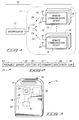
- FIG. 1 is an illustrative diagram of an exemplary wireless communication system.
- FIG. 2 is a diagrammatic representation of an exemplary forward link wireless signal outputted from an interrogator of the wireless communication system shown in FIG. 1 .
- FIG. 3 is an isometric view of an exemplary remote communication device of the wireless communication system shown in FIG. 1 .
- FIG. 4 is a functional block diagram of internal circuitry according to one configuration of the remote communication device.
- FIG. 5 is an illustrative representation of exemplary indication circuitry of the remote communication device of FIG. 4 .
- FIG. 6 is a graphical illustration representing exemplary remote communication device operations.
- FIG. 7 is a graphical illustration showing further details of the illustration of FIG. 6 .
- FIG. 8 is an isometric view of one configuration of the indication circuitry shown in FIG. 5 .
- FIG. 9 is an illustrative representation of another configuration of indication circuitry of the remote communication device.
- Wireless communication system 10 includes an interrogator 12 and at least one remote communication device 14 .
- numerous remote communication devices 14 are provided within wireless communication system 10 although only two such remote communication devices 14 are illustrated in FIG. 1 .
- the particular number of remote communication devices 14 which are in communication with interrogator 12 may change over time.
- more or less remote communication devices 14 can be within a communication range of wireless communication system 10 as objects or packages are moved about.
- only one remote communication device 14 is provided within communication range 11 during a given operation.
- a communication range 11 of interrogator 12 is shown in FIG. 1 .
- Interrogator 12 communicates with remote communication devices 14 located within communication range 11 .
- remote communication devices 14 respectively communicate with interrogator 12 .
- multiple remote communication devices 14 are typically used in the same field of interrogator 12 (i.e., within communications range 11 of interrogator 12 ).
- one aspect of the disclosure provides a remote communication device 14 having indication circuitry (one configuration is shown in FIG. 3) configured to assist with the determination of communication range 11 during testing operations.
- a remote configuration device 14 can comprise a device utilized for normal communication and/or testing operations, or alternatively, for testing operations only.
- remote communication device 14 having the indication circuitry of FIG. 3 can be moved throughout an area larger than and including communication range 11 to assist with the determination of communication range 11 .
- Interrogator 12 can be utilized to output plural forward link wireless signals 22 during testing operations.
- Remote communication device 14 operates to output a human perceptible signal (e.g., human visible light) as described below when it is present within communication range 11 and receiving forward link wireless signals 22 .
- human perceptible signals can be used to assist with determining communication range 11 of interrogator 12 by noting where such human perceptible signals are generated as remote communication device 14 is moved about.
- remote communication device 14 can be utilized to verify correct installation and operation of 10 wireless communication system. Remote communication device 14 indicates proper operation and installation of interrogator 12 responsive to receiving forward link wireless signals 22 .
- remote communication device 14 may be disabled.
- remote communication device 14 may be utilized as the only communication device 14 within communication range 11 during testing or other operations.
- plural remote communication devices 14 are provided within communication range 11 as previously described.
- wireless communication system 10 is configured as an electronic identification system. Other configurations of wireless communication system 10 are possible. Remote communication devices 14 can be individually associated with respective objects 16 , such as packages in inventory. Wireless communication system 10 can also be used in other applications including other identification applications.
- remote communication devices 14 depicted in FIG. 1 are associated with respective objects 16 , it is to be understood that one or more remote communication devices 14 may be provided within communication range 11 without an associated object 16 .
- An exemplary application can include utilization of such an unassociated remote communication device 14 to determine communication range 11 of wireless communication system 10 .
- Remote communication devices 14 individually comprise a wireless identification device in the described arrangement. Other configurations of remote communication devices 14 are possible.
- An exemplary wireless identification device is a radio frequency identification device (RFID).
- RFID radio frequency identification device
- remote communication devices 14 individually include an antenna 18 for wireless or radio frequency transmission by the respective remote communication device 14 .
- Remote communication devices 14 further individually include an antenna 20 for wireless or radio frequency reception by the respective remote communication device 14 .
- the antennas 18 , 20 are microstrip antennas.
- interrogator 12 transmits and receive radio frequency communications to and from interrogator 12 .
- An exemplary interrogator is described in commonly assigned U.S. patent application Ser. No. 08/907,689, filed Aug. 8, 1997, now abandoned, and incorporated herein by reference.
- interrogator 12 includes an antenna 13 as well as dedicated transmitting and receiving circuitry. In one embodiment, such circuitry is complementary to that implemented within individual remote communication devices 14 .
- Interrogator 12 and remote communication devices 14 communicate via an electromagnetic link, such as via an RF link (e.g., at microwave frequencies, in one embodiment), so all transmissions by interrogator 12 are heard by remote communication devices 14 within communication range 11 .
- Interrogator 12 transmits forward link wireless signals 22 individually comprising an interrogation signal or command via antenna 13 .
- the depicted forward link wireless signal 22 includes a preamble 23 , barker code 25 , tag identifier (ID) 26 , command 27 , data 28 and check sum 29 .
- Tag identifier 26 can comprise an identifier to identify one or more of remote communication devices 14 in some applications. For example, tag identifier 26 can identify one, more than one, or all of remote communication devices 14 . As described below, typically only the remote communication devices 14 identified within tag identifier 26 process the respective command 27 and data 28 .
- remote communication devices 14 within the appropriate communication range 11 individually receive the incoming interrogation forward link wireless signal 22 via respective antennas 20 .
- individual remote communication devices 14 can respond by generating a response signal and transmitting a return link wireless signal 24 via respective antenna 18 .
- the return link communication signal 24 typically includes information that uniquely identifies, or labels the particular remote communication device 14 that is transmitting. Such may operate to identify a respective object 16 with which the responding remote communication device 14 is associated.
- Exemplary objects 16 include packages in inventory, people, automobiles, animals, etc.
- transmit antenna 18 may be disabled to prevent the emission of the return link wireless signal 24 .
- remote communication device 14 can be included in any appropriate packaging or housing 30 .
- Various methods of manufacturing housings are described in commonly assigned U.S. patent application Ser. No. 08/800,037, filed Feb. 13, 1997, now U.S. Pat. No. 5,988,510 and incorporated herein by reference.
- An exemplary housing 30 includes an ultrasonically welded plastic injection molded case. Housing 30 is provided about a substrate 31 and at least some of the circuitry of remote communication device 14 . Housing 30 can be configured as a case about substrate 31 to enclose most if not all of the internal components of remote communication device 14 . More specifically, circuitry of remote communication device 14 is provided upon substrate 31 in one embodiment.
- An exemplary substrate 31 is FR 4 board. Circuit components of remote communication device 14 may be attached to substrate 31 using pick-and-place processing techniques.
- FIG. 3 shows but one embodiment of remote communication device 14 in the form of a card or badge including housing 30 of plastic or other suitable material.
- a face of housing 30 has visual identification features such as graphics, text, information found on identification or credit cards, etc. (not shown).
- Housing 30 can also be formed as a miniature housing encasing the internal circuitry and power supply 16 to define a tag which can be supported by object 16 (e.g., hung from an object, affixed to an object, etc.). Other forms of housings 30 are employed in alternative embodiments.
- remote communication device 14 includes communication circuitry 32 , a power source 34 and indication circuitry 36 .
- Communication circuitry 32 includes a small outline integrated circuit (SOIC) as described in the above-incorporated patent application Ser. No. 08/705,043, filed Aug. 29, 1996.
- Exemplary communication circuitry 32 is available from Micron Communications Inc., 3176 South Denver Way, Boise, Id. 83705 under the trademark Microstamp Engine (TM) and having designations MSEM256X10SG, MT59RC256R1FG-5.
- TM Microstamp Engine
- Power source 34 is connected to supply power to communication circuitry 32 and indication circuitry 36 .
- power source 34 comprises one or more batteries. Individual batteries can take any suitable form. Preferably, the battery type will be selected depending on weight, size, and life requirements for a particular application.
- a suitable battery is a thin profile button-type cell forming a small and thin energy cell more commonly utilized in watches and small electronic devices requiring a thin profile.
- a conventional button-type cell has a pair of electrodes, an anode formed by one face and a cathode formed by an opposite face.
- power source 34 comprises a series connected pair of button type cells. In alternative embodiments, other types of suitable power source are employed. Suitable batteries of power source 34 individually include a 3 Volt battery having designation CR2016 available from Eveready Battery Co. Two such batteries can be coupled in series for a 6 Volt output of power source 34 in one embodiment.
- communication circuitry 32 is coupled with substrate 31 and is configured to at least one of receive wireless signals and communicate wireless signals. Exemplary received and communicated wireless signals comprise radio frequency signals as previously described.
- communication circuitry 32 comprises transponder circuitry configured to output the reply or return link wireless identification signal responsive to the reception of a forward link wireless interrogation signal generated within interrogator 12 .
- Indication circuitry 36 is coupled with substrate 31 and communication circuitry 32 .
- indication circuitry 36 includes an indicator 38 to indicate operation of remote communication device 14 .
- Remote communication device 14 can be configured such that indication circuitry 36 indicates at least one of reception of wireless signals and generation of a response signal.
- Indication circuitry 36 may also be configured to indicate the outputting of wireless signals from remote communication device 14 .
- Remote communication device 12 having indication circuitry 38 can also be configured to provide additional indication operations in addition to those described herein. Exemplary additional indication operations of remote communication device 12 are described in a commonly assigned U.S. Patent Application entitled “Radio Frequency Identification Devices, Remote Communication Devices, Identification Systems, Communication Methods, and Identification Methods”, naming Scott T. Trosper as inventor, filed the same day as the present application, having attorney docket number MI40-197 now U.S. Patent Application Ser. No. 09/354,249 filed Jul. 29, 1999, and incorporated herein by reference, and in a commonly assigned U.S. Patent Application entitled “Radio Frequency Identification Devices, Remote Communication Devices, Wireless Communication Systems, and Methods of Indicating Operation”, naming Scott T. Trosper as inventor, filed the same day as the present application, having attorney docket number MI40-218 now U.S. Patent Application Ser. No. 09/363,945 filed Jul. 29, 1999, and incorporated herein by reference.
- Indication circuitry 36 includes indicator 38 configured to emit a human perceptible signal to indicate operation of the remote communication device 14 in accordance with a preferred configuration.
- indicator 38 is configured to visually indicate operation of remote communication device 14 .
- indicator 38 can include at least one light emitting device, such as a light emitting diode (LED), to emit a signal visually perceptible to humans.
- An exemplary LED has designation L20265-ND and is available from Digi-Key Corp.
- Indication circuitry 36 can also include other indicators 38 for indicating operation of remote communication device 14 .
- Another exemplary indicator 38 includes an audible device, such as a buzzer. Indicator 38 can have other configurations.
- remote communication device 14 is configured such that indicator 38 of indication circuitry 36 outwardly emits the human perceptible signal or otherwise indicates operation outside of housing 30 .
- indicator 38 may extend through housing 30 as shown and is externally visible.
- housing 30 is provided about substrate 31 and internal circuitry with indication circuitry 36 at least partially outwardly exposed as illustrated.
- communication circuitry 32 of remote communication device 14 includes a single die in accordance with the described embodiment having a transmitter 40 , a receiver 42 , a memory 44 , and a microprocessor 46 .
- Microprocessor 46 is coupled to transmitter 40 , receiver 42 , and memory 44 as described in U.S. patent application Ser. No. 08/705,043.
- transmitter 40 is configured to reply using wireless communications. Such can include backscatter communications. Alternatively, transmitter 40 may be disabled (e.g., in some testing operations).
- Forward link wireless signals 22 are received within antenna 20 and applied to receiver 42 .
- the forward link wireless signals 22 can be specific to individual remote communication devices 14 , or intended to apply to some or all remote communication devices 14 within communication range 11 .
- Microprocessor 46 is configured to process the signals received by receiver 42 . Responsive to the content of a received forward link wireless signal 22 , microprocessor 46 can formulate a response signal which is applied to transmitter 40 and emitted as the return link wireless signal 24 if transmit antenna 18 is enabled. The response signal can include modulation to provide modulated backscatter communications. Transmitter 40 operates to output return link wireless signals 24 using antenna 18 . As previously described, transmitter 40 may be configured for backscatter communications. For example, antenna 18 can be configured as a dipole antenna and transmitter 40 can selectively short halves of the dipole antenna configuration to selectively reflect a continuous wave signal generated by interrogator 12 .
- the SOIC of communication circuitry 32 includes plural pin connections, some of which are illustrated in FIG. 5 .
- a pin 4 is coupled with an internal current source (not shown) which is configured to output a response signal, such as a current signal, to provide backscatter communications.
- the response signal outputted from pin 4 corresponds to the control signal utilized to control modulation of the continuous wave signal during backscatter communications.
- Plural pins 5 , 6 of communication circuitry 32 can be coupled with antenna 18 .
- pins 5 , 6 can be coupled with respective halves of the dipole antenna configuration to implement backscatter communications.
- a switch (not shown) selectively shorts pins 5 , 6 to implement the appropriate backscatter modulation communications corresponding to the response signal.
- a pin 13 of communication circuitry 32 is a ground voltage reference pin.
- pins 4 , 13 are coupled with indication circuitry 36 .
- the depicted indication circuitry 36 includes indicator 38 , transistor 50 , resistor 52 and capacitor 54 arranged as illustrated.
- capacitor 54 is a 0.1 ⁇ F SmT capacitor having designation PCC104BCT-ND available from Digi-Key Corp.
- resistor 52 is a 620 Ohm 1 ⁇ 8th Watt SmT resistor having designation P620ETR-ND available from Digi-Key Corp.
- Transistor 50 is a ZVN3306FCT-ND N-Channel MOSFET transistor available from Digi-Key Corp.
- remote communication device 14 including indication circuitry 36 can be moved within an area including communication range 11 .
- Interrogator 12 can be provided in a mode to continually transmit an identify command which prompts a return message from all remote communication devices 14 within communication range 11 .
- remote communication device 14 having indication circuitry 36 configured as shown can assist with the determination of communication range 11 .
- remote communication device 14 formulates a response signal and a return link wireless signal 24 if antenna 18 is enabled.
- Microprocessor 46 formulates a response signal corresponding to return link wireless signal 24 and transmitter 40 is configured to output the return link wireless signal 24 according to the response signal from microprocessor 46 .
- the response signal from microprocessor 46 is also applied via pin 4 to indication circuitry 36 .
- wireless communications via antenna 18 can remain enabled or, alternatively, be disabled if return link communication signals are undesired.
- Microprocessor 46 outputs the response signal in the form of a current signal via pin 4 to indication circuitry 36 .
- Pin 4 can be coupled with the gate (G) of transistor 50 .
- the drain (D) connection is coupled with the source (S) connection of transistor 50 .
- Such closes the circuitry within indication circuitry 36 and illuminates indicator 38 comprising a light emitting device.
- a typical response signal from microprocessor 46 is 20 ms in the described embodiment. Such results in a visible flashing of indicator 38 in the described embodiment corresponding to received forward link wireless signals 22 .
- the indication of operations of remote communication device 14 using indicator 38 is responsive to processing of forward link wireless signal 22 and generation of a response signal corresponding to the return link wireless signal.
- Other configurations for controlling indicator 38 are possible.
- the duration of the return link wireless signal can be adjusted in other configurations to vary the length of the indicating signal using indication circuitry 36 .
- a graph illustrates an exemplary testing operation using a remote communication device 14 having indication circuitry 36 to determine communication range 11 of interrogator 12 in one application. Time progresses from left to right in the graph of FIG. 6. A voltage across resistor 52 of indication circuitry 36 is represented in the vertical direction.
- Remote communication device 14 can be moved throughout an area adjacent wireless communication system 10 . During such movements, remote communication device 14 may be moved in and out of communication range 11 . Such results in the reception of only some of the forward link wireless signals 22 being continually generated using interrogator 12 during testing operations. Accordingly, the generation of responses from microprocessor 46 corresponds to received forward link wireless signals 22 while remote communication device 14 is moved within communication range 11 .
- the generation of a response signal corresponding to return link wireless signal 24 results in a spike 60 .
- the divisions of the illustrated graph are approximately 250 ms and individual spikes 60 are approximately 20 ms in length corresponding to the duration of response signals from microprocessor 46 for generating return link wireless signals 24 .
- the generation of response signals depends upon the movement of the remote communication device 14 with respect to communication range 11 .
- Spikes 60 correspond to remote communication device 14 being within communication range 11 .
- indicator 38 generates some emissions responsive to continuous generation of forward link wireless signals 22 from interrogator 12 and responsive to remote communication device 14 being moved in and out of communication range 11 .
- Spikes 60 correspond to response signals from microprocessor 46 and to the emission of light from indicator 38 . Such can be utilized by an individual to visually determine the boundaries of communication range 11 of interrogator 12 in a given application.
- the number of spikes 60 i.e., outputted as flashes of light from indicator 38 in the described configuration
- one spike 60 is illustrated in detail. Again, time increases in the illustrated graph of FIG. 7 from left to right. The voltage across resistor 52 of indication circuitry 36 is indicated in the vertical direction. Some modulation upon the top portion of spike 60 results due to backscatter modulation of the response signal outputted by microprocessor 46 from pin 4 of communication circuitry 32 . However, the capacitive effect of the gate pin of transistor 50 minimizes such modulation effects upon the operation of indication circuitry 36 .
- SOIC communication circuitry 32 is shown coupled with components of indication circuitry 36 . More specifically, indicator 38 , transistor 50 , resistor 52 , and capacitor 54 are provided upon a PC board 41 .
- PC board 41 is attached in one embodiment to an upper surface 33 of SOIC communication circuitry 32 using Cyandacrylate adhesive.
- PC board 41 additionally includes copper clad traces upon an upper surface 49 to connect components of indication circuitry 36 .
- Wire connections 43 , 45 couple pins of SOIC communication circuitry 32 with various components of indication circuitry 36 .
- Wire connection 43 couples transistor 50 and capacitor 54 with a ground pin 13 of SOIC communication circuitry 32 .
- Wire connection 45 couples transistor 50 with pin 4 of SOIC communication circuitry 32 .
- An additional wire connection 47 couples resistor 52 and capacitor 54 with a positive reference voltage of power source 34 .
- SOIC communication circuitry 32 defines a footprint corresponding to a perimeter 39 of the SOIC package.
- Components of indication circuitry 36 and conductive traces of PC board 41 are preferably provided within perimeter 39 of the SOIC package to minimize effects of such circuitry upon wireless communications of remote communication device 14 .
- indication circuitry 36 a of remote communication device 14 is illustrated.
- the depicted indication circuitry 36 a is coupled with communication circuitry 32 and power source 34 .
- Indication circuitry 36 a can be utilized alone or in combination with indication circuitry 36 described with reference to FIG. 5 above.
- Indication circuitry 36 a is coupled with a data port 35 and a clock output 37 of communication circuitry 32 .
- Port 35 and clock output 37 can respectively comprise pins 17 , 18 of the SOIC.
- Port 35 can comprise a digital port and clock output 37 can comprise a digital clock output.
- the depicted indication circuitry 36 a includes a latch 70 , transistor 50 , indicator 38 , resistor 52 and capacitor 54 .
- Indication circuitry 36 a provides benefits in numerous applications, such as inventory monitoring as an exemplary application. In particular, assuming there are a plurality of objects 16 which are being monitored, remote communication device 14 containing indication circuitry 36 a can be utilized to identify one of more desired specific objects from the remaining objects within inventory.
- a user can input a desired identifier within tag identifier 26 of forward link wireless signal 22 .
- the identifier can correspond to a desired object 16 associated with the remote communication device 14 identified by tag identifier 26 .
- Tag identifier 26 can identify one or more desired remote communication devices 14 to identify one or more objects 16 .
- Interrogator 12 communicates the forward link wireless signal 22 having the proper identifier 26 within communication range 11 .
- Remote communication devices 14 within communication range 11 receive the forward link wireless signal 22 including identifier 26 .
- Individual remote communication devices 14 receiving forward link wireless signal 22 process the received forward link wireless signal 22 .
- Individual remote communication devices 14 identified by the tag identifier 26 proceed to process command 27 .
- Other remote communication devices 14 not identified by tag identifier 26 discard the received forward link wireless signal 22 .
- Command 27 within forward link wireless signal 22 can include a command to write to port 35 of communication circuitry 32 .
- communication circuitry 32 can generate and output a control signal to indication circuitry 36 a .
- Indication circuitry 36 a is configured to receive the control signal and to indicate the operation and presence of the respective remote communication device 14 responsive to the control signal.
- communication circuitry 32 is configured to output a control signal to indication circuitry 38 a comprising data 28 of a received forward link wireless signal 22 . More specifically, command 27 can specify the writing of data 28 contained within received forward link wireless signal 22 to port 35 of communication circuitry 32 .
- Data 28 can comprise a byte for controlling indication circuitry 36 a .
- data 28 can include hex FF to turn on indicator 38 .
- interrogator 12 can communicate another forward link wireless signal 22 including hex 00 within data 28 . Writing of the hex 00 to data port 35 can be utilized to turn off indicator 38 .
- Other data 28 can be supplied within a forward link wireless signal 22 .
- Data port 35 is coupled with a D-input of latch 70 .
- Communication circuitry 32 is configured to output a timing signal to a clock (CLK) input of latch 70 via clock output 37 .
- Latch 70 of indication circuitry 36 a is configured to receive the control signal including data 28 from communication circuitry 32 .
- Latch 70 is configured to store data 28 received from communication circuitry 32 .
- latch 70 is configured to selectively assert an output signal via the Q-output responsive to the received control signal in the described embodiment.
- the Q-output is coupled with gate (G) electrode of transistor 50 .
- the source (S) electrode of transistor 50 is coupled with ground and the drain (D) electrode of transistor 50 is coupled with indicator 38 .
- Indicator 38 is selectively coupled with latch 70 via transistor 50 and is configured to output a signal to indicate the operation and presence of the respective remote communication device 14 responsive to the control signal (e.g., data 28 ) received within latch 70 from communication circuitry 32 .
- indicator 38 is preferably configured to emit a human perceptible signal to indicate the presence of the respective remote communication device 14 .
- indicator 38 comprises a light emitting device such as a light emitting diode (LED) configured to visually indicate the operation and presence of the respective remote communication device 14 .
- LED light emitting diode
- the remote communication devices 14 identified by identifier 26 of forward link wireless signal 22 indicate operation and presence using indication circuitry 36 a . Accordingly, such operates to identify desired objects 16 from other objects 16 according to one application.
Abstract
Description
Claims (6)
Priority Applications (1)
| Application Number | Priority Date | Filing Date | Title |
|---|---|---|---|
| US09/640,477 US6452496B1 (en) | 1999-07-29 | 2000-08-16 | Radio frequency identification devices and a method of determining a communication range |
Applications Claiming Priority (2)
| Application Number | Priority Date | Filing Date | Title |
|---|---|---|---|
| US09/363,944 US6466130B2 (en) | 1999-07-29 | 1999-07-29 | Wireless communication devices, wireless communication systems, communication methods, methods of forming radio frequency identification devices, methods of testing wireless communication operations, radio frequency identification devices, and methods of forming radio frequency identification devices |
| US09/640,477 US6452496B1 (en) | 1999-07-29 | 2000-08-16 | Radio frequency identification devices and a method of determining a communication range |
Related Parent Applications (1)
| Application Number | Title | Priority Date | Filing Date |
|---|---|---|---|
| US09/363,944 Division US6466130B2 (en) | 1999-07-29 | 1999-07-29 | Wireless communication devices, wireless communication systems, communication methods, methods of forming radio frequency identification devices, methods of testing wireless communication operations, radio frequency identification devices, and methods of forming radio frequency identification devices |
Publications (1)
| Publication Number | Publication Date |
|---|---|
| US6452496B1 true US6452496B1 (en) | 2002-09-17 |
Family
ID=23432388
Family Applications (4)
| Application Number | Title | Priority Date | Filing Date |
|---|---|---|---|
| US09/363,944 Expired - Lifetime US6466130B2 (en) | 1999-07-29 | 1999-07-29 | Wireless communication devices, wireless communication systems, communication methods, methods of forming radio frequency identification devices, methods of testing wireless communication operations, radio frequency identification devices, and methods of forming radio frequency identification devices |
| US09/640,477 Expired - Lifetime US6452496B1 (en) | 1999-07-29 | 2000-08-16 | Radio frequency identification devices and a method of determining a communication range |
| US09/655,660 Expired - Lifetime US6326889B1 (en) | 1999-07-29 | 2000-09-06 | Radio frequency identification device and methods of determining a communication range of an interrogator of a wireless identification system |
| US10/004,135 Expired - Fee Related US6545605B2 (en) | 1999-07-29 | 2001-10-18 | Methods of determining a communications range of an interrogator of a wireless identification system and methods of verifying operation of a wireless identification system |
Family Applications Before (1)
| Application Number | Title | Priority Date | Filing Date |
|---|---|---|---|
| US09/363,944 Expired - Lifetime US6466130B2 (en) | 1999-07-29 | 1999-07-29 | Wireless communication devices, wireless communication systems, communication methods, methods of forming radio frequency identification devices, methods of testing wireless communication operations, radio frequency identification devices, and methods of forming radio frequency identification devices |
Family Applications After (2)
| Application Number | Title | Priority Date | Filing Date |
|---|---|---|---|
| US09/655,660 Expired - Lifetime US6326889B1 (en) | 1999-07-29 | 2000-09-06 | Radio frequency identification device and methods of determining a communication range of an interrogator of a wireless identification system |
| US10/004,135 Expired - Fee Related US6545605B2 (en) | 1999-07-29 | 2001-10-18 | Methods of determining a communications range of an interrogator of a wireless identification system and methods of verifying operation of a wireless identification system |
Country Status (1)
| Country | Link |
|---|---|
| US (4) | US6466130B2 (en) |
Cited By (13)
| Publication number | Priority date | Publication date | Assignee | Title |
|---|---|---|---|---|
| US20040172180A1 (en) * | 2003-01-21 | 2004-09-02 | Bowman Tom W. | Wireless communications device for use in tires |
| US6845279B1 (en) | 2004-02-06 | 2005-01-18 | Integrated Technologies, Inc. | Error proofing system for portable tools |
| US6951596B2 (en) | 2002-01-18 | 2005-10-04 | Avery Dennison Corporation | RFID label technique |
| US20060111123A1 (en) * | 2002-08-19 | 2006-05-25 | Emerson Nerat | Wide area and large capacity intelligent object tracking system and method |
| US20060208079A1 (en) * | 2005-03-21 | 2006-09-21 | Industrial Technology Research Institute | RFID testing system |
| US20060284727A1 (en) * | 2005-06-16 | 2006-12-21 | Psc Scanning, Inc. | Method and system with functionality for finding range between an electronic tag reader and tag |
| US20070001814A1 (en) * | 2005-06-14 | 2007-01-04 | Steinke Kurt E | Wireless tag ranging |
| US20070035395A1 (en) * | 1999-07-29 | 2007-02-15 | Trosper Scott T | Wireless communication devices, radio frequency identification devices, radio frequency identification device communication systems, wireless communication methods, and radio frequency identification device communication methods |
| US20080111675A1 (en) * | 2006-11-10 | 2008-05-15 | Micron Technology, Inc. | Tracking systems, passive RFIDs, methods of locating and identifying RFIDs, and methods of tracking items |
| US20080186178A1 (en) * | 2007-02-07 | 2008-08-07 | Micron Technology, Inc. | RFIDS, interrogators, indication systems, methods of determining a bi-directional communication range of an interrogator, methods of activating an observable indicator, and methods of indicating bi-directional functionality of a radio connection |
| US7500307B2 (en) | 2004-09-22 | 2009-03-10 | Avery Dennison Corporation | High-speed RFID circuit placement method |
| US7555826B2 (en) | 2005-12-22 | 2009-07-07 | Avery Dennison Corporation | Method of manufacturing RFID devices |
| US8531297B2 (en) | 2005-04-25 | 2013-09-10 | Avery Dennison Corporation | High-speed RFID circuit placement method and device |
Families Citing this family (80)
| Publication number | Priority date | Publication date | Assignee | Title |
|---|---|---|---|---|
| FR2784485B1 (en) * | 1998-10-07 | 2001-02-23 | Pierre Sorriaux | SPACE SEPARATION WARNING DEVICE BEYOND A PREDETERMINED LIMIT |
| US6466130B2 (en) * | 1999-07-29 | 2002-10-15 | Micron Technology, Inc. | Wireless communication devices, wireless communication systems, communication methods, methods of forming radio frequency identification devices, methods of testing wireless communication operations, radio frequency identification devices, and methods of forming radio frequency identification devices |
| US6650695B1 (en) | 1999-08-03 | 2003-11-18 | Intel Corporation | Wireless digital data transmission from a passive transceiver |
| US6677852B1 (en) * | 1999-09-22 | 2004-01-13 | Intermec Ip Corp. | System and method for automatically controlling or configuring a device, such as an RFID reader |
| US7080037B2 (en) * | 1999-09-28 | 2006-07-18 | Chameleon Network Inc. | Portable electronic authorization system and method |
| US7340439B2 (en) * | 1999-09-28 | 2008-03-04 | Chameleon Network Inc. | Portable electronic authorization system and method |
| US20050108096A1 (en) * | 1999-09-28 | 2005-05-19 | Chameleon Network Inc. | Portable electronic authorization system and method |
| EP1216460A1 (en) * | 1999-09-28 | 2002-06-26 | Chameleon Network Inc. | Portable electronic authorization system and associated method |
| US7161476B2 (en) | 2000-07-26 | 2007-01-09 | Bridgestone Firestone North American Tire, Llc | Electronic tire management system |
| EP2272689A3 (en) | 2000-07-26 | 2011-03-09 | Bridgestone Americas Tire Operations, LLC | Electronic tire management system |
| US8266465B2 (en) | 2000-07-26 | 2012-09-11 | Bridgestone Americas Tire Operation, LLC | System for conserving battery life in a battery operated device |
| US6940392B2 (en) * | 2001-04-24 | 2005-09-06 | Savi Technology, Inc. | Method and apparatus for varying signals transmitted by a tag |
| WO2002025984A1 (en) * | 2000-09-20 | 2002-03-28 | Seiko Epson Corporation | Radio information distribution system, radio information distribution apparatus, and portable radio device |
| US6837427B2 (en) | 2001-11-21 | 2005-01-04 | Goliath Solutions, Llc. | Advertising compliance monitoring system |
| US7374096B2 (en) | 2001-11-21 | 2008-05-20 | Goliath Solutions, Llc | Advertising compliance monitoring system |
| US6951305B2 (en) | 2001-11-21 | 2005-10-04 | Goliath Solutions, Llc. | Advertising compliance monitoring system |
| EP1488385A2 (en) * | 2002-03-19 | 2004-12-22 | Chameleon Network Inc. | Portable electronic authorization system and method |
| US7424974B2 (en) * | 2002-09-03 | 2008-09-16 | Ricoh Company, Ltd. | Techniques that facilitate tracking of physical locations of paper documents |
| US7884955B2 (en) * | 2002-09-03 | 2011-02-08 | Ricoh Company, Ltd. | Techniques for performing actions based upon physical locations of paper documents |
| US6860422B2 (en) | 2002-09-03 | 2005-03-01 | Ricoh Company, Ltd. | Method and apparatus for tracking documents in a workflow |
| US7652555B2 (en) * | 2002-09-03 | 2010-01-26 | Ricoh Company, Ltd. | Container for storing objects |
| US7506250B2 (en) * | 2002-09-03 | 2009-03-17 | Ricoh Company, Ltd. | Techniques for determining electronic document information for paper documents |
| US7129840B2 (en) * | 2002-09-03 | 2006-10-31 | Ricoh Company, Ltd. | Document security system |
| US7911358B2 (en) * | 2002-10-08 | 2011-03-22 | Johnson Controls Technology Company | System and method for enrollment of a remotely controlled device in a trainable transmitter |
| JP4227105B2 (en) * | 2002-10-08 | 2009-02-18 | ジョンソン コントロールズ テクノロジー カンパニー | System and method for wireless control of remote electronic systems including location-based functionality |
| US7009519B2 (en) * | 2002-11-21 | 2006-03-07 | S.C. Johnson & Sons, Inc. | Product dispensing controlled by RFID tags |
| US7151435B2 (en) * | 2002-11-26 | 2006-12-19 | Ge Medical Systems Information Technologies, Inc. | Method and apparatus for identifying a patient |
| US6982639B2 (en) | 2002-11-26 | 2006-01-03 | Ge Medical Systems Information Technologies, Inc. | Wireless subject locator |
| US7225992B2 (en) * | 2003-02-13 | 2007-06-05 | Avery Dennison Corporation | RFID device tester and method |
| JP2004280434A (en) * | 2003-03-14 | 2004-10-07 | Seiko Epson Corp | Noncontact data communication system, noncontact identification tag and noncontact identification tag control program |
| US8681000B2 (en) | 2003-04-09 | 2014-03-25 | Visible Assets, Inc. | Low frequency inductive tagging for lifecycle management |
| US8026819B2 (en) * | 2005-10-02 | 2011-09-27 | Visible Assets, Inc. | Radio tag and system |
| US8378841B2 (en) * | 2003-04-09 | 2013-02-19 | Visible Assets, Inc | Tracking of oil drilling pipes and other objects |
| US7145437B2 (en) * | 2003-10-16 | 2006-12-05 | Nokia Corporation | Method, terminal and computer program product for adjusting power consumption of a RFID reader associated with a mobile terminal |
| US7626505B2 (en) * | 2004-09-28 | 2009-12-01 | Visible Assets, Inc | RF tags for tracking and locating travel bags |
| US7680691B2 (en) * | 2004-04-29 | 2010-03-16 | S.C. Johnson & Son, Inc. | Inventory management system using RFID |
| US7158032B2 (en) * | 2004-05-20 | 2007-01-02 | Xerox Corporation | Diagnosis of programmable modules |
| US7038582B2 (en) * | 2004-06-10 | 2006-05-02 | The Chamberlain Group, Inc. | Access control system wireless transmission link test method |
| US7307527B2 (en) * | 2004-07-01 | 2007-12-11 | Avery Dennison Corporation | RFID device preparation system and method |
| US7532965B2 (en) * | 2005-01-25 | 2009-05-12 | Johnson Controls Technology Company | System and method for providing user interface functionality based on location |
| US7477152B2 (en) * | 2005-03-14 | 2009-01-13 | Avery Dennison Corporation | RFID application test systems and methods |
| US7742444B2 (en) | 2005-03-15 | 2010-06-22 | Qualcomm Incorporated | Multiple other sector information combining for power control in a wireless communication system |
| US7411498B2 (en) * | 2005-04-07 | 2008-08-12 | Avery Dennison | RFID testing and classification systems and methods |
| US7295117B2 (en) * | 2005-04-07 | 2007-11-13 | Avery Dennison | RFID device test thresholds systems and methods |
| US7430398B2 (en) * | 2005-05-03 | 2008-09-30 | International Business Machines Corporation | Radio frequency identification (RFID) system for dynamically and automatically establishing communication between a mobile wireless communicating device and a data processing system |
| US7298267B2 (en) * | 2005-05-09 | 2007-11-20 | Avery Dennison | RFID test interface systems and methods |
| US7298266B2 (en) * | 2005-05-09 | 2007-11-20 | Avery Dennison | RFID communication systems and methods |
| US7359823B2 (en) * | 2005-05-25 | 2008-04-15 | Avery Dennison | RFID device variable test systems and methods |
| US8750908B2 (en) | 2005-06-16 | 2014-06-10 | Qualcomm Incorporated | Quick paging channel with reduced probability of missed page |
| US9055552B2 (en) | 2005-06-16 | 2015-06-09 | Qualcomm Incorporated | Quick paging channel with reduced probability of missed page |
| EP3168790B1 (en) * | 2005-08-22 | 2019-05-08 | Avery Dennison Retail Information Services, LLC | Method of making rfid devices |
| KR20070087740A (en) * | 2005-09-27 | 2007-08-29 | 삼성전자주식회사 | Diagnosis system and method in an image forming apparatus |
| US9069933B1 (en) | 2005-09-28 | 2015-06-30 | Visible Assets, Inc. | Secure, networked portable storage device |
| WO2007050936A1 (en) * | 2005-10-27 | 2007-05-03 | Qualcomm Incorporated | A method and apparatus for processing time overlapping non sticky (ns) unicast and sticky assignments |
| US20090207790A1 (en) | 2005-10-27 | 2009-08-20 | Qualcomm Incorporated | Method and apparatus for settingtuneawaystatus in an open state in wireless communication system |
| US20070262866A1 (en) * | 2005-11-14 | 2007-11-15 | Ronald Eveland | Multi-Dimensional Broadband Track and Trace Sensor Radio Frequency Identification Device |
| US20070229264A1 (en) * | 2005-11-14 | 2007-10-04 | Ronald Eveland | Software method and system for encapsulation of RFID data into a standardized globally routable format |
| US20070115130A1 (en) * | 2005-11-14 | 2007-05-24 | Ronald Eveland | Multi-dimensional, broadband track and trace sensor radio frequency identification device |
| US7154283B1 (en) | 2006-02-22 | 2006-12-26 | Avery Dennison Corporation | Method of determining performance of RFID devices |
| CA2881613C (en) * | 2006-04-19 | 2017-11-14 | Stanley Kyi | Systems and methods for ex vivo organ care |
| US8226003B2 (en) | 2006-04-27 | 2012-07-24 | Sirit Inc. | Adjusting parameters associated with leakage signals |
| US7310070B1 (en) | 2006-08-23 | 2007-12-18 | Goliath Solutions, Llc | Radio frequency identification shelf antenna with a distributed pattern for localized tag detection |
| US8760267B2 (en) * | 2006-08-28 | 2014-06-24 | Gentex Corporation | System and method for enrollment of a remotely controlled device in a trainable transmitter |
| EP1903347A1 (en) * | 2006-09-25 | 2008-03-26 | Marco Porro | Device for controlling personal belongings |
| KR20090076994A (en) * | 2006-10-31 | 2009-07-13 | 솔리코어 인코포레이티드 | Powered authenticating cards |
| JP5684475B2 (en) * | 2006-10-31 | 2015-03-11 | ソリコア インコーポレイテッドSOLICORE,Incorporated | Battery powered devices |
| WO2008056739A1 (en) * | 2006-11-10 | 2008-05-15 | Renesas Technology Corp. | System debug method, system debug apparatus, data processor, wireless communication interface ic, and interface method |
| US7967214B2 (en) * | 2006-12-29 | 2011-06-28 | Solicore, Inc. | Card configured to receive separate battery |
| US8181879B2 (en) * | 2006-12-29 | 2012-05-22 | Solicore, Inc. | Mailing apparatus for powered cards |
| US8248212B2 (en) | 2007-05-24 | 2012-08-21 | Sirit Inc. | Pipelining processes in a RF reader |
| US7696885B2 (en) * | 2007-06-21 | 2010-04-13 | Round Rock Research, Llc | Methods and systems of attaching a radio transceiver to an antenna |
| US7884753B2 (en) * | 2008-02-04 | 2011-02-08 | Honeywell International Inc. | Apparatus and method for ranging of a wireless transceiver with a switching antenna |
| US8427316B2 (en) | 2008-03-20 | 2013-04-23 | 3M Innovative Properties Company | Detecting tampered with radio frequency identification tags |
| US8446256B2 (en) | 2008-05-19 | 2013-05-21 | Sirit Technologies Inc. | Multiplexing radio frequency signals |
| US20100253502A1 (en) * | 2009-01-05 | 2010-10-07 | Susan Duncan | Product locator and method for locating a product |
| US8169312B2 (en) | 2009-01-09 | 2012-05-01 | Sirit Inc. | Determining speeds of radio frequency tags |
| US8416079B2 (en) | 2009-06-02 | 2013-04-09 | 3M Innovative Properties Company | Switching radio frequency identification (RFID) tags |
| US8325019B2 (en) | 2010-09-13 | 2012-12-04 | Ricoh Company, Ltd. | Motion tracking techniques for RFID tags |
| US10062025B2 (en) | 2012-03-09 | 2018-08-28 | Neology, Inc. | Switchable RFID tag |
| JP7194292B2 (en) * | 2019-04-17 | 2022-12-21 | アップル インコーポレイテッド | radio localizable tag |
Citations (62)
| Publication number | Priority date | Publication date | Assignee | Title |
|---|---|---|---|---|
| US4075632A (en) | 1974-08-27 | 1978-02-21 | The United States Of America As Represented By The United States Department Of Energy | Interrogation, and detection system |
| US4223830A (en) | 1978-08-18 | 1980-09-23 | Walton Charles A | Identification system |
| US4236068A (en) | 1979-03-29 | 1980-11-25 | Walton Charles A | Personal identification and signaling system |
| US4476469A (en) | 1980-11-14 | 1984-10-09 | Lander David R | Means for assisting in locating an object |
| US4675656A (en) | 1984-03-16 | 1987-06-23 | Narcisse Bernadine O | Out-of-range personnel monitor and alarm |
| US4926182A (en) | 1986-05-30 | 1990-05-15 | Sharp Kabushiki Kaisha | Microwave data transmission apparatus |
| US5087906A (en) | 1990-03-05 | 1992-02-11 | Motorola, Inc. | Selective call receiver having a light channel for providing a visual alert |
| US5113183A (en) | 1987-06-16 | 1992-05-12 | Casio Computer Co., Ltd. | Remote code transmission system between a nameplate apparatus and a data processing apparatus |
| US5119069A (en) | 1989-08-07 | 1992-06-02 | Shmuel Hershkovitz | Apparatus and method for locating boundaries of detection zones covered by a passive infrared detection system |
| US5151684A (en) * | 1991-04-12 | 1992-09-29 | Johnsen Edward L | Electronic inventory label and security apparatus |
| US5214410A (en) | 1989-07-10 | 1993-05-25 | Csir | Location of objects |
| US5337041A (en) | 1992-04-13 | 1994-08-09 | Lorri Friedman | Personal safety guard system for stray person or pet |
| US5416486A (en) | 1993-11-08 | 1995-05-16 | Apti, Inc. | Identification/security tag system employing electronic doppler shifting and/or rectenna structure |
| US5450070A (en) | 1992-03-17 | 1995-09-12 | Massar; Sheppard | Electronic missing file locator system |
| US5539393A (en) | 1991-03-22 | 1996-07-23 | Esel-Krabbe Systems A/S | Information system |
| US5550547A (en) | 1994-09-12 | 1996-08-27 | International Business Machines Corporation | Multiple item radio frequency tag identification protocol |
| US5565858A (en) | 1994-09-14 | 1996-10-15 | Northrop Grumman Corporation | Electronic inventory system for stacked containers |
| US5570080A (en) | 1992-04-24 | 1996-10-29 | Toshio Inoue | Theft prevention tab device having alarm mechanism housed therein |
| US5581257A (en) | 1991-09-24 | 1996-12-03 | Gordian Holding Corporation | Radio frequency automatic identification system |
| US5617060A (en) | 1994-04-28 | 1997-04-01 | Qualcomm Incorporated | Method and apparatus for automatic gain control and DC offset cancellation in quadrature receiver |
| US5621412A (en) | 1994-04-26 | 1997-04-15 | Texas Instruments Incorporated | Multi-stage transponder wake-up, method and structure |
| US5649296A (en) | 1995-06-19 | 1997-07-15 | Lucent Technologies Inc. | Full duplex modulated backscatter system |
| US5649295A (en) | 1995-06-19 | 1997-07-15 | Lucent Technologies Inc. | Dual mode modulated backscatter system |
| US5652569A (en) | 1994-09-02 | 1997-07-29 | Paul Joseph Gerstenberger | Child alarm |
| US5656998A (en) | 1993-08-31 | 1997-08-12 | Kubota Corporation | Detector for theft prevention |
| US5686902A (en) | 1990-06-15 | 1997-11-11 | Texas Instruments Incorporated | Communication system for communicating with tags |
| US5689240A (en) | 1996-06-05 | 1997-11-18 | C.O.P. Corp. | Child monitor system |
| US5742238A (en) | 1995-09-01 | 1998-04-21 | Emtrak, Inc. | System for communication between a central controller and items in a factory using infrared light |
| US5771002A (en) | 1997-03-21 | 1998-06-23 | The Board Of Trustees Of The Leland Stanford Junior University | Tracking system using radio frequency signals |
| US5777561A (en) | 1996-09-30 | 1998-07-07 | International Business Machines Corporation | Method of grouping RF transponders |
| US5787174A (en) | 1992-06-17 | 1998-07-28 | Micron Technology, Inc. | Remote identification of integrated circuit |
| US5796351A (en) | 1995-04-04 | 1998-08-18 | Fujitsu Limited | System for providing information about exhibition objects |
| US5841770A (en) | 1992-12-15 | 1998-11-24 | Micron Technology, Inc. | Data communication system using indentification protocol |
| US5850181A (en) | 1996-04-03 | 1998-12-15 | International Business Machines Corporation | Method of transporting radio frequency power to energize radio frequency identification transponders |
| US5861817A (en) | 1997-07-02 | 1999-01-19 | Douglas A. Palmer | System for, and method of, displaying prices on tags in supermarkets |
| US5874902A (en) | 1996-07-29 | 1999-02-23 | International Business Machines Corporation | Radio frequency identification transponder with electronic circuit enabling/disabling capability |
| US5905429A (en) | 1997-04-25 | 1999-05-18 | City Of Lights, Inc. | Audio label |
| US5929778A (en) | 1994-11-10 | 1999-07-27 | Rikagaku Kenkyusho | Data carrier system |
| US5940006A (en) | 1995-12-12 | 1999-08-17 | Lucent Technologies Inc. | Enhanced uplink modulated backscatter system |
| US5939981A (en) | 1998-01-28 | 1999-08-17 | Renney; Marjorie | Item locator with attachable receiver/transmitter |
| US5949328A (en) | 1995-03-03 | 1999-09-07 | Latty; James A. | Apparatus and method for locatable encoding alarms |
| US5952922A (en) | 1996-12-31 | 1999-09-14 | Lucent Technologies Inc. | In-building modulated backscatter system |
| US5963133A (en) | 1997-07-18 | 1999-10-05 | Monjo; Nicolas | Electronic tag |
| US5963177A (en) | 1997-05-16 | 1999-10-05 | Micron Communications, Inc. | Methods of enhancing electronmagnetic radiation properties of encapsulated circuit, and related devices |
| US5966082A (en) | 1997-05-23 | 1999-10-12 | Intemec Ip Corp. | Method of flagging partial write in RF tags |
| US5988510A (en) | 1997-02-13 | 1999-11-23 | Micron Communications, Inc. | Tamper resistant smart card and method of protecting data in a smart card |
| US6008727A (en) | 1998-09-10 | 1999-12-28 | Xerox Corporation | Selectively enabled electronic tags |
| US6023610A (en) | 1996-12-18 | 2000-02-08 | Micron Technology, Inc. | Communication system including diversity antenna queuing |
| US6024285A (en) | 1997-08-19 | 2000-02-15 | Micron Technology, Inc. | Wireless communication devices and methods of forming wireless communication devices |
| US6027027A (en) | 1996-05-31 | 2000-02-22 | Lucent Technologies Inc. | Luggage tag assembly |
| US6031459A (en) | 1998-07-22 | 2000-02-29 | Micron Technology, Inc. | Wireless communication devices, radio frequency identification devices, and methods of forming wireless communication devices and radio frequency identification devices |
| US6052062A (en) | 1997-08-20 | 2000-04-18 | Micron Technology, Inc. | Cards, communication devices, and methods of forming and encoding visibly perceptible information on the same |
| US6078260A (en) | 1998-12-21 | 2000-06-20 | Sony Corporation | Method and apparatus for keeping track of children |
| US6130623A (en) | 1996-12-31 | 2000-10-10 | Lucent Technologies Inc. | Encryption for modulated backscatter systems |
| US6130602A (en) | 1996-05-13 | 2000-10-10 | Micron Technology, Inc. | Radio frequency data communications device |
| US6133830A (en) * | 1998-06-19 | 2000-10-17 | Lexent Technologies, Inc. | Motion sensitive anti-theft device with alarm screening |
| US6137422A (en) | 1999-05-21 | 2000-10-24 | Micron Technology, Inc. | Communications system and method with D/A converter |
| US6147602A (en) | 1998-03-11 | 2000-11-14 | Bender; Sheldon | Luggage locator system |
| US6184789B1 (en) | 1999-06-22 | 2001-02-06 | Xerox Corporation | Method and apparatus for visually determining object location |
| US6289209B1 (en) | 1996-12-18 | 2001-09-11 | Micron Technology, Inc. | Wireless communication system, radio frequency communications system, wireless communications method, radio frequency communications method |
| US6326889B1 (en) | 1999-07-29 | 2001-12-04 | Micron Technology, Inc. | Radio frequency identification device and methods of determining a communication range of an interrogator of a wireless identification system |
| US6333690B1 (en) | 1995-03-29 | 2001-12-25 | Medical Tracking Systems | Wide area multipurpose tracking system |
Family Cites Families (5)
| Publication number | Priority date | Publication date | Assignee | Title |
|---|---|---|---|---|
| DE19542203A1 (en) | 1995-11-13 | 1997-05-15 | Schuler Pressen Gmbh & Co | Convertible multi-station press |
| US6275142B1 (en) | 1998-09-15 | 2001-08-14 | International Business Machines Corporation | Interactive enhancement for printed books |
| US6084512A (en) | 1998-10-02 | 2000-07-04 | Lucent Technologies, Inc. | Method and apparatus for electronic labeling and localizing |
| US6198392B1 (en) | 1999-02-10 | 2001-03-06 | Micron Technology, Inc. | Communications system and method with A/D converter |
| US6304183B1 (en) | 2000-12-15 | 2001-10-16 | Charles O. Causey | Suitcase locating device |
-
1999
- 1999-07-29 US US09/363,944 patent/US6466130B2/en not_active Expired - Lifetime
-
2000
- 2000-08-16 US US09/640,477 patent/US6452496B1/en not_active Expired - Lifetime
- 2000-09-06 US US09/655,660 patent/US6326889B1/en not_active Expired - Lifetime
-
2001
- 2001-10-18 US US10/004,135 patent/US6545605B2/en not_active Expired - Fee Related
Patent Citations (63)
| Publication number | Priority date | Publication date | Assignee | Title |
|---|---|---|---|---|
| US4075632A (en) | 1974-08-27 | 1978-02-21 | The United States Of America As Represented By The United States Department Of Energy | Interrogation, and detection system |
| US4223830A (en) | 1978-08-18 | 1980-09-23 | Walton Charles A | Identification system |
| US4236068A (en) | 1979-03-29 | 1980-11-25 | Walton Charles A | Personal identification and signaling system |
| US4476469A (en) | 1980-11-14 | 1984-10-09 | Lander David R | Means for assisting in locating an object |
| US4675656A (en) | 1984-03-16 | 1987-06-23 | Narcisse Bernadine O | Out-of-range personnel monitor and alarm |
| US4926182A (en) | 1986-05-30 | 1990-05-15 | Sharp Kabushiki Kaisha | Microwave data transmission apparatus |
| US5113183A (en) | 1987-06-16 | 1992-05-12 | Casio Computer Co., Ltd. | Remote code transmission system between a nameplate apparatus and a data processing apparatus |
| US5214410A (en) | 1989-07-10 | 1993-05-25 | Csir | Location of objects |
| US5119069A (en) | 1989-08-07 | 1992-06-02 | Shmuel Hershkovitz | Apparatus and method for locating boundaries of detection zones covered by a passive infrared detection system |
| US5087906A (en) | 1990-03-05 | 1992-02-11 | Motorola, Inc. | Selective call receiver having a light channel for providing a visual alert |
| US5686902A (en) | 1990-06-15 | 1997-11-11 | Texas Instruments Incorporated | Communication system for communicating with tags |
| US5539393A (en) | 1991-03-22 | 1996-07-23 | Esel-Krabbe Systems A/S | Information system |
| US5151684A (en) * | 1991-04-12 | 1992-09-29 | Johnsen Edward L | Electronic inventory label and security apparatus |
| US5581257A (en) | 1991-09-24 | 1996-12-03 | Gordian Holding Corporation | Radio frequency automatic identification system |
| US5450070A (en) | 1992-03-17 | 1995-09-12 | Massar; Sheppard | Electronic missing file locator system |
| US5337041A (en) | 1992-04-13 | 1994-08-09 | Lorri Friedman | Personal safety guard system for stray person or pet |
| US5570080A (en) | 1992-04-24 | 1996-10-29 | Toshio Inoue | Theft prevention tab device having alarm mechanism housed therein |
| US5787174A (en) | 1992-06-17 | 1998-07-28 | Micron Technology, Inc. | Remote identification of integrated circuit |
| US5841770A (en) | 1992-12-15 | 1998-11-24 | Micron Technology, Inc. | Data communication system using indentification protocol |
| US5656998A (en) | 1993-08-31 | 1997-08-12 | Kubota Corporation | Detector for theft prevention |
| US5416486A (en) | 1993-11-08 | 1995-05-16 | Apti, Inc. | Identification/security tag system employing electronic doppler shifting and/or rectenna structure |
| US5621412A (en) | 1994-04-26 | 1997-04-15 | Texas Instruments Incorporated | Multi-stage transponder wake-up, method and structure |
| US5617060A (en) | 1994-04-28 | 1997-04-01 | Qualcomm Incorporated | Method and apparatus for automatic gain control and DC offset cancellation in quadrature receiver |
| US5652569A (en) | 1994-09-02 | 1997-07-29 | Paul Joseph Gerstenberger | Child alarm |
| US5550547A (en) | 1994-09-12 | 1996-08-27 | International Business Machines Corporation | Multiple item radio frequency tag identification protocol |
| US5565858A (en) | 1994-09-14 | 1996-10-15 | Northrop Grumman Corporation | Electronic inventory system for stacked containers |
| US5929778A (en) | 1994-11-10 | 1999-07-27 | Rikagaku Kenkyusho | Data carrier system |
| US5949328A (en) | 1995-03-03 | 1999-09-07 | Latty; James A. | Apparatus and method for locatable encoding alarms |
| US6333690B1 (en) | 1995-03-29 | 2001-12-25 | Medical Tracking Systems | Wide area multipurpose tracking system |
| US5796351A (en) | 1995-04-04 | 1998-08-18 | Fujitsu Limited | System for providing information about exhibition objects |
| US5649295A (en) | 1995-06-19 | 1997-07-15 | Lucent Technologies Inc. | Dual mode modulated backscatter system |
| US5649296A (en) | 1995-06-19 | 1997-07-15 | Lucent Technologies Inc. | Full duplex modulated backscatter system |
| US5742238A (en) | 1995-09-01 | 1998-04-21 | Emtrak, Inc. | System for communication between a central controller and items in a factory using infrared light |
| US5940006A (en) | 1995-12-12 | 1999-08-17 | Lucent Technologies Inc. | Enhanced uplink modulated backscatter system |
| US5850181A (en) | 1996-04-03 | 1998-12-15 | International Business Machines Corporation | Method of transporting radio frequency power to energize radio frequency identification transponders |
| US6130602A (en) | 1996-05-13 | 2000-10-10 | Micron Technology, Inc. | Radio frequency data communications device |
| US6027027A (en) | 1996-05-31 | 2000-02-22 | Lucent Technologies Inc. | Luggage tag assembly |
| US5689240A (en) | 1996-06-05 | 1997-11-18 | C.O.P. Corp. | Child monitor system |
| US5874902A (en) | 1996-07-29 | 1999-02-23 | International Business Machines Corporation | Radio frequency identification transponder with electronic circuit enabling/disabling capability |
| US5995019A (en) | 1996-09-30 | 1999-11-30 | Intermec I.P. Corp | Method for communicating with RF transponders |
| US5777561A (en) | 1996-09-30 | 1998-07-07 | International Business Machines Corporation | Method of grouping RF transponders |
| US6023610A (en) | 1996-12-18 | 2000-02-08 | Micron Technology, Inc. | Communication system including diversity antenna queuing |
| US6289209B1 (en) | 1996-12-18 | 2001-09-11 | Micron Technology, Inc. | Wireless communication system, radio frequency communications system, wireless communications method, radio frequency communications method |
| US5952922A (en) | 1996-12-31 | 1999-09-14 | Lucent Technologies Inc. | In-building modulated backscatter system |
| US6130623A (en) | 1996-12-31 | 2000-10-10 | Lucent Technologies Inc. | Encryption for modulated backscatter systems |
| US5988510A (en) | 1997-02-13 | 1999-11-23 | Micron Communications, Inc. | Tamper resistant smart card and method of protecting data in a smart card |
| US5771002A (en) | 1997-03-21 | 1998-06-23 | The Board Of Trustees Of The Leland Stanford Junior University | Tracking system using radio frequency signals |
| US5905429A (en) | 1997-04-25 | 1999-05-18 | City Of Lights, Inc. | Audio label |
| US5963177A (en) | 1997-05-16 | 1999-10-05 | Micron Communications, Inc. | Methods of enhancing electronmagnetic radiation properties of encapsulated circuit, and related devices |
| US5966082A (en) | 1997-05-23 | 1999-10-12 | Intemec Ip Corp. | Method of flagging partial write in RF tags |
| US5861817A (en) | 1997-07-02 | 1999-01-19 | Douglas A. Palmer | System for, and method of, displaying prices on tags in supermarkets |
| US5963133A (en) | 1997-07-18 | 1999-10-05 | Monjo; Nicolas | Electronic tag |
| US6024285A (en) | 1997-08-19 | 2000-02-15 | Micron Technology, Inc. | Wireless communication devices and methods of forming wireless communication devices |
| US6052062A (en) | 1997-08-20 | 2000-04-18 | Micron Technology, Inc. | Cards, communication devices, and methods of forming and encoding visibly perceptible information on the same |
| US5939981A (en) | 1998-01-28 | 1999-08-17 | Renney; Marjorie | Item locator with attachable receiver/transmitter |
| US6147602A (en) | 1998-03-11 | 2000-11-14 | Bender; Sheldon | Luggage locator system |
| US6133830A (en) * | 1998-06-19 | 2000-10-17 | Lexent Technologies, Inc. | Motion sensitive anti-theft device with alarm screening |
| US6031459A (en) | 1998-07-22 | 2000-02-29 | Micron Technology, Inc. | Wireless communication devices, radio frequency identification devices, and methods of forming wireless communication devices and radio frequency identification devices |
| US6008727A (en) | 1998-09-10 | 1999-12-28 | Xerox Corporation | Selectively enabled electronic tags |
| US6078260A (en) | 1998-12-21 | 2000-06-20 | Sony Corporation | Method and apparatus for keeping track of children |
| US6137422A (en) | 1999-05-21 | 2000-10-24 | Micron Technology, Inc. | Communications system and method with D/A converter |
| US6184789B1 (en) | 1999-06-22 | 2001-02-06 | Xerox Corporation | Method and apparatus for visually determining object location |
| US6326889B1 (en) | 1999-07-29 | 2001-12-04 | Micron Technology, Inc. | Radio frequency identification device and methods of determining a communication range of an interrogator of a wireless identification system |
Non-Patent Citations (4)
| Title |
|---|
| http:// www.aimglobal.org/technologies/rfid/; Aim, Inc.; "RFID"; Mar. 9, 2001; pp. 1-2. |
| SN: 08/907,689, Wood, Jr., Original Application; filed Aug. 8, 1997. |
| SN: 09/363,945, Scott T. Trosper, Original Application; filed Jul. 29, 1999. |
| SN: 09/364,249, Scott T. Trosper, Original Application; filed Jul. 29, 1999. |
Cited By (31)
| Publication number | Priority date | Publication date | Assignee | Title |
|---|---|---|---|---|
| US20070290851A1 (en) * | 1999-07-29 | 2007-12-20 | Trosper Scott T | Radio Frequency Identification Devices, Remote Communication Devices, Identification Systems, Communication Methods, and Identification Methods |
| US7518515B2 (en) | 1999-07-29 | 2009-04-14 | Keystone Technology Solutions, Llc | Method and system for RFID communication |
| US20100013637A1 (en) * | 1999-07-29 | 2010-01-21 | Keystone Technology Solutions, Llc | Radio Frequency Identification Devices, Remote Communication Devices, Identification Systems, Communication Methods, and Identification Methods |
| US7737851B2 (en) | 1999-07-29 | 2010-06-15 | Round Rock Research, Llc | Radio frequency identification devices, remote communication devices, identification systems, communication methods, and identification methods |
| US8487766B2 (en) | 1999-07-29 | 2013-07-16 | Round Rock Research, LLP | Radio frequency identification devices, remote communication devices, identification systems, communication methods, and identification methods |
| US20070035395A1 (en) * | 1999-07-29 | 2007-02-15 | Trosper Scott T | Wireless communication devices, radio frequency identification devices, radio frequency identification device communication systems, wireless communication methods, and radio frequency identification device communication methods |
| US8004407B2 (en) | 1999-07-29 | 2011-08-23 | Round Rock Research, Llc | Radio frequency identification devices, remote communication devices, identification systems, communication methods, and identification methods |
| US8253565B2 (en) | 1999-07-29 | 2012-08-28 | Round Rock Research, Llc | Radio frequency identification devices, remote communication devices, identification systems, communication methods, and identification methods |
| US9495632B2 (en) | 2001-02-02 | 2016-11-15 | Avery Dennison Corporation | RFID label technique |
| US6951596B2 (en) | 2002-01-18 | 2005-10-04 | Avery Dennison Corporation | RFID label technique |
| US8246773B2 (en) | 2002-01-18 | 2012-08-21 | Avery Dennison Corporation | RFID label technique |
| US7932812B2 (en) | 2002-08-19 | 2011-04-26 | Purelink Technology Inc. | Wide area and large capacity intelligent object tracking system and method |
| US20060111123A1 (en) * | 2002-08-19 | 2006-05-25 | Emerson Nerat | Wide area and large capacity intelligent object tracking system and method |
| US20040172180A1 (en) * | 2003-01-21 | 2004-09-02 | Bowman Tom W. | Wireless communications device for use in tires |
| US6845279B1 (en) | 2004-02-06 | 2005-01-18 | Integrated Technologies, Inc. | Error proofing system for portable tools |
| USRE41160E1 (en) | 2004-02-06 | 2010-03-02 | Gilmore Curt D | Error proofing system for portable tools |
| USRE41185E1 (en) * | 2004-02-06 | 2010-03-30 | Gilmore Curt D | Error proofing system for portable tools |
| US7500307B2 (en) | 2004-09-22 | 2009-03-10 | Avery Dennison Corporation | High-speed RFID circuit placement method |
| US7669318B2 (en) | 2004-09-22 | 2010-03-02 | Avery Dennison Corporation | High-speed RFID circuit placement method |
| US8020283B2 (en) | 2004-09-22 | 2011-09-20 | Avery Dennison Corporation | High-speed RFID circuit placement device |
| US20060208079A1 (en) * | 2005-03-21 | 2006-09-21 | Industrial Technology Research Institute | RFID testing system |
| US8531297B2 (en) | 2005-04-25 | 2013-09-10 | Avery Dennison Corporation | High-speed RFID circuit placement method and device |
| US7405662B2 (en) | 2005-06-14 | 2008-07-29 | Datalogic Mobile, Inc. | Wireless tag ranging |
| US20070001814A1 (en) * | 2005-06-14 | 2007-01-04 | Steinke Kurt E | Wireless tag ranging |
| US20060284727A1 (en) * | 2005-06-16 | 2006-12-21 | Psc Scanning, Inc. | Method and system with functionality for finding range between an electronic tag reader and tag |
| US7555826B2 (en) | 2005-12-22 | 2009-07-07 | Avery Dennison Corporation | Method of manufacturing RFID devices |
| US7874493B2 (en) | 2005-12-22 | 2011-01-25 | Avery Dennison Corporation | Method of manufacturing RFID devices |
| US20110084808A1 (en) * | 2006-11-10 | 2011-04-14 | Round Rock Research, Llc | Tracking systems, methods of locating and identifying rfids, and methods of tracking items |
| US7855643B2 (en) | 2006-11-10 | 2010-12-21 | Round Rock Research, Llc | Tracking systems, passive RFIDs, methods of locating and identifying RFIDs, and methods of tracking items |
| US20080111675A1 (en) * | 2006-11-10 | 2008-05-15 | Micron Technology, Inc. | Tracking systems, passive RFIDs, methods of locating and identifying RFIDs, and methods of tracking items |
| US20080186178A1 (en) * | 2007-02-07 | 2008-08-07 | Micron Technology, Inc. | RFIDS, interrogators, indication systems, methods of determining a bi-directional communication range of an interrogator, methods of activating an observable indicator, and methods of indicating bi-directional functionality of a radio connection |
Also Published As
| Publication number | Publication date |
|---|---|
| US6326889B1 (en) | 2001-12-04 |
| US20020041235A1 (en) | 2002-04-11 |
| US20010054959A1 (en) | 2001-12-27 |
| US6545605B2 (en) | 2003-04-08 |
| US6466130B2 (en) | 2002-10-15 |
Similar Documents
| Publication | Publication Date | Title |
|---|---|---|
| US6452496B1 (en) | Radio frequency identification devices and a method of determining a communication range | |
| US7123148B2 (en) | Wireless communication devices, radio frequency identification devices, radio frequency identification device communication systems, wireless communication methods, and radio frequency identification device communication methods | |
| US6459376B2 (en) | Radio frequency identification devices, remote communication devices, wireless communication systems, and methods of indicating operation | |
| US7710273B2 (en) | Remote communication devices, radio frequency identification devices, wireless communication systems, wireless communication methods, radio frequency identification device communication methods, and methods of forming a remote communication device | |
| US7327263B2 (en) | Communications system and method with A/D converter | |
| US6002343A (en) | Changing Indicia in an electronic tag when tampered with | |
| US7884724B2 (en) | Radio frequency data communications device with selectively removable antenna portion and method | |
| US6420961B1 (en) | Wireless communication systems, interfacing devices, communication methods, methods of interfacing with an interrogator, and methods of operating an interrogator | |
| ES2590956T3 (en) | RFID tag detection techniques in electronic article surveillance systems using frequency mixing | |
| US6342843B1 (en) | Communications system and method with D/A converter | |
| US20130127597A1 (en) | Wireless communication systems, and methods of communication within a wireless communication system | |
| CN218332609U (en) | RFID-based electronic tag and sorting system |
Legal Events
| Date | Code | Title | Description |
|---|---|---|---|
| STCF | Information on status: patent grant |
Free format text: PATENTED CASE |
|
| CC | Certificate of correction | ||
| FPAY | Fee payment |
Year of fee payment: 4 |
|
| AS | Assignment |
Owner name: KEYSTONE TECHNOLOGY SOLUTIONS, LLC, IDAHO Free format text: ASSIGNMENT OF ASSIGNORS INTEREST;ASSIGNOR:MICRON TECHNOLOGY, INC.;REEL/FRAME:019825/0542 Effective date: 20070628 Owner name: KEYSTONE TECHNOLOGY SOLUTIONS, LLC,IDAHO Free format text: ASSIGNMENT OF ASSIGNORS INTEREST;ASSIGNOR:MICRON TECHNOLOGY, INC.;REEL/FRAME:019825/0542 Effective date: 20070628 |
|
| AS | Assignment |
Owner name: ROUND ROCK RESEARCH, LLC,NEW YORK Free format text: ASSIGNMENT OF ASSIGNORS INTEREST;ASSIGNOR:MICRON TECHNOLOGY, INC.;REEL/FRAME:023786/0416 Effective date: 20091223 Owner name: ROUND ROCK RESEARCH, LLC, NEW YORK Free format text: ASSIGNMENT OF ASSIGNORS INTEREST;ASSIGNOR:MICRON TECHNOLOGY, INC.;REEL/FRAME:023786/0416 Effective date: 20091223 |
|
| AS | Assignment |
Owner name: MICRON TECHNOLOGY, INC., IDAHO Free format text: ASSIGNMENT OF ASSIGNORS INTEREST;ASSIGNOR:KEYSTONE TECHNOLOGY SOLUTIONS, LLC;REEL/FRAME:023839/0881 Effective date: 20091222 Owner name: MICRON TECHNOLOGY, INC.,IDAHO Free format text: ASSIGNMENT OF ASSIGNORS INTEREST;ASSIGNOR:KEYSTONE TECHNOLOGY SOLUTIONS, LLC;REEL/FRAME:023839/0881 Effective date: 20091222 |
|
| FPAY | Fee payment |
Year of fee payment: 8 |
|
| FPAY | Fee payment |
Year of fee payment: 12 |