US6400707B1 - Real time firewall security - Google Patents
Real time firewall security Download PDFInfo
- Publication number
- US6400707B1 US6400707B1 US09/141,726 US14172698A US6400707B1 US 6400707 B1 US6400707 B1 US 6400707B1 US 14172698 A US14172698 A US 14172698A US 6400707 B1 US6400707 B1 US 6400707B1
- Authority
- US
- United States
- Prior art keywords
- filter device
- gateway
- packet
- signaling
- control processor
- Prior art date
- Legal status (The legal status is an assumption and is not a legal conclusion. Google has not performed a legal analysis and makes no representation as to the accuracy of the status listed.)
- Expired - Lifetime
Links
Images


Classifications
-
- H—ELECTRICITY
- H04—ELECTRIC COMMUNICATION TECHNIQUE
- H04L—TRANSMISSION OF DIGITAL INFORMATION, e.g. TELEGRAPHIC COMMUNICATION
- H04L65/00—Network arrangements, protocols or services for supporting real-time applications in data packet communication
- H04L65/10—Architectures or entities
- H04L65/102—Gateways
- H04L65/1033—Signalling gateways
- H04L65/104—Signalling gateways in the network
-
- H—ELECTRICITY
- H04—ELECTRIC COMMUNICATION TECHNIQUE
- H04L—TRANSMISSION OF DIGITAL INFORMATION, e.g. TELEGRAPHIC COMMUNICATION
- H04L63/00—Network architectures or network communication protocols for network security
- H04L63/02—Network architectures or network communication protocols for network security for separating internal from external traffic, e.g. firewalls
- H04L63/0227—Filtering policies
- H04L63/0263—Rule management
-
- H—ELECTRICITY
- H04—ELECTRIC COMMUNICATION TECHNIQUE
- H04L—TRANSMISSION OF DIGITAL INFORMATION, e.g. TELEGRAPHIC COMMUNICATION
- H04L65/00—Network arrangements, protocols or services for supporting real-time applications in data packet communication
- H04L65/10—Architectures or entities
- H04L65/102—Gateways
- H04L65/1023—Media gateways
- H04L65/103—Media gateways in the network
-
- H—ELECTRICITY
- H04—ELECTRIC COMMUNICATION TECHNIQUE
- H04M—TELEPHONIC COMMUNICATION
- H04M7/00—Arrangements for interconnection between switching centres
- H04M7/006—Networks other than PSTN/ISDN providing telephone service, e.g. Voice over Internet Protocol (VoIP), including next generation networks with a packet-switched transport layer
- H04M7/0078—Security; Fraud detection; Fraud prevention
-
- H—ELECTRICITY
- H04—ELECTRIC COMMUNICATION TECHNIQUE
- H04M—TELEPHONIC COMMUNICATION
- H04M7/00—Arrangements for interconnection between switching centres
- H04M7/12—Arrangements for interconnection between switching centres for working between exchanges having different types of switching equipment, e.g. power-driven and step by step or decimal and non-decimal
- H04M7/1205—Arrangements for interconnection between switching centres for working between exchanges having different types of switching equipment, e.g. power-driven and step by step or decimal and non-decimal where the types of switching equipement comprises PSTN/ISDN equipment and switching equipment of networks other than PSTN/ISDN, e.g. Internet Protocol networks
-
- H—ELECTRICITY
- H04—ELECTRIC COMMUNICATION TECHNIQUE
- H04L—TRANSMISSION OF DIGITAL INFORMATION, e.g. TELEGRAPHIC COMMUNICATION
- H04L65/00—Network arrangements, protocols or services for supporting real-time applications in data packet communication
- H04L65/1066—Session management
- H04L65/1101—Session protocols
Definitions
- This invention relates to methods and systems for managing security in communication sessions across networks, and more particularly, to a methodology and system for managing security in telephony sessions over hybrid networks such as combined switched telephone networks and packet switched internetworks, such as the Internet.
- the invention relates to an improved firewall mechanism and methodology for providing real time firewall security.
- a secure network such as a switched telephone network
- an unsecured network such as the Internet
- PSTN public switched telephone network
- Packet filtering is a method which allows connectivity yet provides security by controlling the traffic being passed, thus preventing unauthorized communication attempts and attacks upon the protected network.
- Current implementation of packet filtering allows specification of access list tables according to a fixed format. This lacks flexibility and entails excessive expense when the firewall is designed to cope with the problems presented in packetized voice.
- the monitor computer screen is used to define network objects such as workstations, gateways, and other computer hardware connected to the system.
- Various devices are grouped together such as, for example, the finance department, the research and development department, and the directors of the company. This is intended to provide flexibility in tailoring security rules to manage various filters to provide the degree of access desired for the various computers or the devices which are grouped together. It is thus possible to have the chief financial officer as well as other higher-ranking officials of the company, such as the CEO and the directors, able to communicate directly with the finance group, but filter out communications from other groups. This allows the administrator or system operator to provide internal security as well as external security.
- Network services are also represented on the screen from which the administrator or operator works. Graphic symbols and color are utilized to ease the burden on the operator. This makes it possible for the operator to enter new rules without the need for writing, compiling and checking new code for this purpose.
- the information entered on the GUI is then converted to a filter script containing the rules to be utilized by the packet filter.
- proxy server or proxy application for purposes of providing a firewall.
- latency increases exponentially as the number is increased.
- Application proxies would not be capable of handling the number of calls expected in this application except at a prohibitive cost.
- It is still a further object of the invention to provide a system for conducting a voice communication through a hybrid network which comprises a packet internetwork connected to a switched telephone network via a static filter device, a packet switch, a gateway, and a control processor connected to the packet switch and to the filter device, wherein the filter device generates a real time copy of call set up signaling therethrough, which copy of set up signaling is delivered through the packet switch to the control processor, with the control processor generating therefrom a filter device control signal which is delivered to the filter device and which reconfigures the filter device.
- FIG. 1 is a high-level functional block diagram of a telephone network arranged to provide connectivity to a computer through the Internet.
- FIG. 2 is a high level diagram of basically the same network as shown in FIG. 1, which has been provided with firewalls.
- FIG. 3 is a detailed depiction of a firewall mechanism according to one preferred embodiment of the invention.
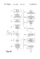
- FIG. 4 is a flow diagram depicting a sequence of operation for the hybrid network shown in FIGS. 2 and 3 .
- FIG. 1 shows a simplified version of one embodiment of such a network.
- packet switched and circuit switched networks are separately shown as the clouds 106 and 108 .
- the end-to-end system connects a laptop computer 110 and a telephone 112 .
- These constitute what is here referred to as the PC user call control object and the POTS (Plain Old Telephone Service) user.
- a directory or directory services object 114 and an authentication and security accounting object 116 are coupled to the packet switched IP routed network 106 . These constitute a directory which matches called party exchange numbers (NPA-NXX) to IP addresses of gateways which serve the respective exchange numbers.
- the authentication and security accounting object 116 comprises a database handling authorization, usage recording and pricing, as presently described.
- An Internet Telephony Gateway or ITG server 118 connects the packet switched and circuit switched networks. This may be sometimes referred to herein as the call control object.
- the computer 110 may be linked to the packet switched network via any available computer to Internet link.
- the connection between the circuit switched network and the telephone terminal may be any of the conventional links including POTS.
- the database 116 represents the network element used in this architecture to perform customer authentication, call authorization, usage accounting, and usage pricing.
- the authentication database 116 is accessed by the gateway 118 during a call set up when the gateway receives an authorization request from a service subscriber. Communication between the gateway and the database is preferably encrypted and secure.
- the authorization request relayed by the gateway to the database 116 typically consists of an account number and password provided by the PC User.
- the authentication database 116 checks the account password and available account balance. If the password is correct and the account remaining balance permits the call to be established, then the database responds affirmatively to the gateway.
- the authentication database 118 also retains data indicating that a call associated with that account is in progress.
- the operation of the system in establishing a call connection may be described as follows:
- the actual call set up signaling flow starts at the point where the user has established IP layer connectivity with the network, and has invoked the voice over Internet (V/IP) software application.
- V/IP voice over Internet
- the customer will boot the PC, and connect to the IP network following their existing procedures for network access.
- V/IP application either as a plug-in to an existing browser or as a standalone application. When launched, this application will present a template of fields which are required to initiate a call.
- the customer will populate a “telephone number to be called” data field.
- the customer will also either populate his/her account number and password, or the application will reapply this data if it has been previously saved within the application.
- the customer will then initiate the call.
- the call's completion status will be presented in real-time to the user by the application (via a visual display).
- the PC user initiates a call via the PC's voice over IP (V/IP) software.
- This software application invokes the directory 114 to obtain the IP address of the destination gateway. Based on the dialed number submitted by the PC application as described in the foregoing preliminary procedure, the directory 114 returns the IP address of the associated gateway 118 .
- the PC's V/IP software application invokes the gateway 118 to set up a call by passing to the gateway the number to be called, the user's account number, and a password.
- the gateway invokes the authentication database 116 in order to receive authorization to proceed with the call.
- the authentication database will pass the authorization information back to the gateway.
- the gateway will establish the PSTN connection, and notify the client software that the call is proceeding.
- the PC will respond to the network that it recognizes that a connection has been established. Timing of the call's duration can be initiated, and any usage measurements will indicate that the call is billable.
- FIG. 2 there is shown a high level diagram of basically the same network as FIG. 1, which has been provided with firewalls.
- a cloud which represents a packet switched IP internetwork, such as the Internet.
- PSTNs switched telephone networks
- the telephone networks contain end offices (not separately shown) which serve subscribers 214 , 216 , 218 , and 220 .
- POTS plain old telephone service
- the telephone networks 212 and 214 are respectively connected to the Internet via T-1 or primary rate ISDN links 222 , 224 and 226 , 228 , gateways or servers 230 and 232 , and firewalls 234 and 236 .
- a computer or PC 238 is connected directly to the Internet.
- the PC is equipped with a headset and microphone or a telephone handset 240 .
- a control center 242 is shown by broken lines as including an authentication database 244 and directory database 246 . These are connected to the IP network through a firewall 248 .
- This arrangement may be used to provide voice paths through the IP network from telephone to telephone or computer to telephone or vice versa. Without the addition of the firewalls, the establishment of a voice path from the computer to one of the telephones would be as just described with respect to FIG. 1 .
- FIG. 3 there is shown a detailed depiction of a firewall mechanism according to the invention.
- an IP network which may be the Internet
- cloud 310 linked to a switched telephone network, which may be a PSTN 312 .
- the telephone network is connected by T-1 or PRI ISDN links 314 , 316 , and 318 to gateways or servers 320 , 322 , and 324 .
- the IP network 310 has connected thereto a computer or PC 326 having a telephone 328 . Also connected to the IP network is a control center indicated by the broken lines 330 . As in FIG. 2, the control center includes an authorization database 332 and a directory database 334 . The two databases are connected to the IP network through a firewall mechanism 336 , presently to be described in detail.
- the IP network 310 is connected to the gateways 320 , 322 and 324 through a firewall mechanism 338 constructed according to a preferred embodiment of the invention.
- the firewall mechanism includes a static firewall router 340 .
- This may be, for example, a BorderGuard 2000 Internet router for providing firewall protection.
- the BorderGuard 2000 is marketed by StorageTek—Network Systems Group, and is also available from Mercury Technology Services, Inc., a Florida based company.
- the static firewall 340 is connected to a hub packet switch 342 .
- the switch may be, for example, an Ethernet packet switch such as the standard Cisco 1900 marketed by Cisco Systems, Inc.
- the firewall 340 and the switch 342 are connected to a control processor 344 .
- the firewall router operates in a static bridged mode.
- a router typically operates in a manner to do some routing at the third layer of the OSI stack.
- routing at the third layer is not desired because it incurs an unacceptable amount of latency.
- the unit takes the signal only up to the second or network layer.
- the static firewall acts as a rule based packet filter.
- the rules are automatically and dynamically set. There is no requirement for an administrator periodically setting up detailed lists. The security is applied to each port on the fly to provide extremely fast operation, in sharp contrast to that which would be obtained from a proxy server.
- the methodology provides the generation and application of customized filters for each conversation.
- Each filter is unique to a specific conversation.
- the filter disappears on termination of the conversation.
- a high level of security is obtained.
- This is effected automatically in dynamic fashion which permits very fast response.
- the system provides an acceptable level of security for packetized voice communication.
- the static rule filter or firewall 340 replicates or copies the signaling which occurs during set up of a communication path.
- the ability to perform such copying is a little used functionality which exists in conventional static firewalls, such as the BorderGuard 2000.
- the two data streams which are produced, i.e., the original data stream and the replicated or copied stream, are then delivered to the packet switch 342 .
- the switch passes the original stream to the addressed gateway 320 , 322 , or 324 .
- the switch delivers the replicated stream to the control processor 344 .
- the control processor monitors and analyzes the set up signaling which follows. It derives from that signaling critical parameters which thereafter are used to govern the ensuing conversation. These parameters include but are not limited to source and destination, IP addresses, packet size and protocol, codec, format, gateway and port.
- the control processor then compiles a filter code from those parameters, and sends the filter code via an RS 232 link 345 to the static rule governed filter or firewall 340 .
- the control processor 344 need not conduct constant surveillance of the conversation stream which passes through the firewall after the set up is complete and the communication link has been established.
- the PC 326 is booted, runs its voice over Internet application, and connects to its connection or entry server (not shown) to the Internet. Using its voice over Internet application, the PC dials a telephone number and indicates a desire to make an Internet telephony call to that number. As previously described, this dialing is effected by the PC caller populating appropriate fields in the voice over Internet application. Also based on this information, the PC 326 connects to the authorization platform 332 , presents its request and is authenticated and registered. The directory database 334 is then accessed for the IP address of the gateway serving that exchange and number. The directory database provides the IP address of the server 324 which serves that number, and which can serve as a hop-off gateway to leave the Internet for the telephone network.
- the PC application notes that address, and uses it to send a Q.931 message to set up a conversation.
- the Q.931 message reaches the static firewall 340 which has only one port open for Q.931 messages.
- the firewall checks the message to confirm that it is a valid Q.931 stream. If it is not, it is dropped and a message sent back to the client PC saying that the host or gateway is unreachable. If it is a valid Q.931 stream, has the Q.931 port address in the firewall 340 , and has the IP address of the gateway 324 , the static firewall 340 commences replication of the signaling stream. Both the original stream and the replicated stream are now passed on to the packet switch 342 .
- the packet switch sends the replicated copy of the steam to the control processor 344 . At the same time the packet switch sends the original stream to the gateway 324 .
- the control processor analyzes the replicated stream, notes that it has a request, where it originated, and that it is an H.323 over Q.931 set up signal, and registers this.
- H.323 is a specification recommendation which covers the technical requirements for multimedia communications systems in those situations where the underlying transport is a packet based network (PBN) which may not provide a guaranteed Quality of Service (QOS).
- PBN packet based network
- QOS Quality of Service
- These packet based networks may include Local Area Networks, Enterprise Area Networks, Metropolitan Area Networks, Intra-Networks, and Inter-Networks (including the Internet). They also include the dial-up connections or point-to-point connections over the GSTN or ISDN which use an underlying packet based transport such as PPP.
- Q.931 is the message oriented signaling protocol originally specified for operation over the ISDN D-channel.
- H.323 uses a subset of Q.931 to set-up and take down a communication channel between two H.323 devices.
- the protocol defines what goes into a signaling packet and defines the message type and content. Included are call setup and take down, called party number, calling party number information (including privacy and authenticity indicators), bearer capability (to distinguish, for example, voice versus data for compatibility check between terminals), release of B-Channels and the application and/or announcements in the originating switch upon encountering errors.
- the gateway 324 consults its authorization database, notes that it has a valid customer and sends a negotiation message back to the PC 326 .
- the message contains the proposal of the gateway for a codec and port. This passes through the firewall 340 and the firewall replicates the message and sends it to the control processor 344 .
- the control processor reads and analyzes the replicated message, notes the codec and port, and notes that the gateway has authorized the call.
- the acceptance message is received at the gateway 324 , is read by the gateway, and the gateway returns an acknowledgement to the caller via the switch 342 and firewall 340 . This is replicated by the firewall to the control 344 processor.
- the control processor looks at the replicated stream and registers that a valid conversation has been established on a designated port.
- the control processor now generates a set of security specifications, compiles a filter configuration message, and sends this to the filter or firewall 340 via the RS 232 connection 345 .
- the firewall now sets up a very specific filter for this single conversation.
- the filter will include source and destination, IP addresses, packet size and protocol and port.
- the firewall reconfigures in accord with RS 232 reconfiguration message it received from the control processor.
- the firewall filter now monitors every packet that follows for conformance with the strict filter requirements.
- the control processor drops out and turns to other set-ups.
- the conversation path is established on the designated port and continues until a fault occurs and it is dropped by the firewall, or until one of the parties hangs up.
- the PC 326 receives the message and ascertains that it can use the proposed codec and port.
- the PC now responds to the gateway, expressing agreement to the proposed specifications.
- This response from the PC arrives at the static firewall 340 . It is checked again for format and protocol and is confirmed as having a valid format and protocol.
- the firewall passes the PC acceptance or agreement message through to the gateway 324 and sends a replicated copy to the control processor.
- the method is illustrated in the flow chart shown in FIG. 4 .
- the caller having a computer or PC equipped with a telephone and a telephony application, boots the computer and runs the telephony application to make a telephone call via the Internet.
- the caller connects to its Internet connection server and signals a request to place a call to a telephone number and the IP address for that number.
- connection gateway responds at S 3 , consults the directory database 334 to which it has access, identifies the destination gateway which handles that number, and provides to the caller the IP address of that gateway.
- the caller transmits its Q.931 message addressed to that gateway.
- the transmitted Q.931 message arrives at the static firewall and it is checked to confirm that it is a valid Q.931 stream. If it is not a valid Q.931 stream, the message is dropped and a message is sent back to the caller saying that the host is not available (S 6 ).
- the message which arrived at the firewall is sent to the open Q.931 port. If it has the port ID, and the gateway or server IP address, it is passed through the firewall to the gateway at S 7 .
- the firewall generates a copy of the incoming packets and routes that to the control processor through the switch 342 .
- control processor 344 analyzes the stream and registers that there has been a request.
- the other or main packet steam from the switch arrives at the addressed gateway 324 .
- the gateway consults its authorization database, such as the database 332 , notes that it has a valid customer or client and sends a call set up negotiation message back to the caller PC 326 .
- the set up message contains the proposal of the gateway for a codec and port.
- This set up negotiation message goes to the firewall 340 through the switch 342 .
- the firewall 340 replicates the message and sends it to the control processor 344 through the switch 342 . This is shown at S 11 .
- control processor notes the message protocol and other parameter information which it extracts from the form and content of the message.
- the caller PC notes the port assignment, codec and other parameter information in the message and sends an acceptance and agreement message back to the gateway.
- the control processor receives the message from the caller PC at S 15 , notes and registers that there is agreement.
- the firewall sends the confirmation message on to the gateway.
- the gateway concludes that there is an authorized, agreed upon, and valid conversation or communication setup.
- the gateway thereupon sends its confirmation and proceed message back through the switch and firewall to the caller PC.
- the firewall replicates the proceed message from the gateway and sends the replication to the control processor at S 18 .
- control processor notes and registers that the gateway authorization and proceed signals have been received, and registers that a valid conversation has been cleared for the designated port using the designated codec.
- the control processor based on the information it has gathered in this setup message exchange, compiles the specific parameters which characterize and are to govern this single conversation.
- the control processor generates a filter configuration message. This is shown at S 20 .
- control processor sends an RS 232 message to the firewall to change its configuration in accord with the parameters compiled from the creation of this communication.
- the firewall now is reconfigured pursuant to the signal from the control processor at S 22 .
- the reconfigured static firewall now checks each of these parameters for every packet in the stream to the port designated for this communication. This is shown at S 23 .
- the control processor drops out and goes on to other tasks at S 24 .
- control processor has been depicted as operating according to a preferred mode of the invention.
- control processor in a modified manner wherein additional functions can be performed.
- the firewall can be set to duplicate dropped packets to the control processor.
- the control processor can then provide a notification to an administrator that an attack is occurring from an identified sub-net.
- the control processor can trigger other programmed reactions.
- An alarm message can be delivered, the packet can be logged, or the firewall can be told to shut down.
- control processor or controller is used as an off-line controller. In this manner the controller does not have to monitor a conversation or conduct continuous surveillance. It operates on a replicated stream only during setup for port negotiation, and provides very dynamic capabilities. The combination provides very fast operation and contributes virtually no latency to the communication stream. It provides security in a very real time sense. All of the specific parameters are set in the static and passive filter on-the-fly. The filter then provides full time filtering on a very specific set of specifications or rules which are customized for each communication path and set in the firewall in virtual real time. The arrangement not only provides dynamic port allocation but also provides dynamic set up of customized filter rules on-the-fly.
- control processor or controller is able to handle calls seriatim on an extremely fast basis. Once a set up dialog of signaling is complete the controller is free to move to another task, including the set up of another communication path.
Abstract
Description
Claims (33)
Priority Applications (1)
| Application Number | Priority Date | Filing Date | Title |
|---|---|---|---|
| US09/141,726 US6400707B1 (en) | 1998-08-27 | 1998-08-27 | Real time firewall security |
Applications Claiming Priority (1)
| Application Number | Priority Date | Filing Date | Title |
|---|---|---|---|
| US09/141,726 US6400707B1 (en) | 1998-08-27 | 1998-08-27 | Real time firewall security |
Publications (1)
| Publication Number | Publication Date |
|---|---|
| US6400707B1 true US6400707B1 (en) | 2002-06-04 |
Family
ID=22496956
Family Applications (1)
| Application Number | Title | Priority Date | Filing Date |
|---|---|---|---|
| US09/141,726 Expired - Lifetime US6400707B1 (en) | 1998-08-27 | 1998-08-27 | Real time firewall security |
Country Status (1)
| Country | Link |
|---|---|
| US (1) | US6400707B1 (en) |
Cited By (40)
| Publication number | Priority date | Publication date | Assignee | Title |
|---|---|---|---|---|
| US20010052007A1 (en) * | 2000-01-21 | 2001-12-13 | Nec Corporation | DNS server filter |
| US20020042277A1 (en) * | 2000-10-10 | 2002-04-11 | Smith Steven W. | Subscriber information service center (SISC) |
| US20020054666A1 (en) * | 2000-11-06 | 2002-05-09 | Kevin Kliland | Surveillance arrangement and controller |
| US20020069200A1 (en) * | 2000-01-07 | 2002-06-06 | Geoffrey Cooper | Efficient evaluation of rules |
| US6496477B1 (en) * | 1999-07-09 | 2002-12-17 | Texas Instruments Incorporated | Processes, articles, and packets for network path diversity in media over packet applications |
| WO2003003679A2 (en) * | 2001-06-28 | 2003-01-09 | Emerson Harry E Iii | Telephone central office switch interface with messaging channel for integrating the pstn with the internet |
| US20030028806A1 (en) * | 2001-08-06 | 2003-02-06 | Rangaprasad Govindarajan | Dynamic allocation of ports at firewall |
| US20030140248A1 (en) * | 2002-01-24 | 2003-07-24 | David Izatt | Undetectable firewall |
| US20030145228A1 (en) * | 2002-01-31 | 2003-07-31 | Janne Suuronen | System and method of providing virus protection at a gateway |
| US20040073811A1 (en) * | 2002-10-15 | 2004-04-15 | Aleksey Sanin | Web service security filter |
| US20040100972A1 (en) * | 2001-01-11 | 2004-05-27 | Lumb Anthony Peter | Firewall with index to access rule |
| US6772347B1 (en) * | 1999-04-01 | 2004-08-03 | Juniper Networks, Inc. | Method, apparatus and computer program product for a network firewall |
| US20040170176A1 (en) * | 1999-03-17 | 2004-09-02 | Broadcom Corporation | Method for handling IP multicast packets in network switch |
| US20040249963A1 (en) * | 2001-09-25 | 2004-12-09 | Karl Klaghofer | Network gateway device and communications system for real item communication connections |
| US20040250112A1 (en) * | 2000-01-07 | 2004-12-09 | Valente Luis Filipe Pereira | Declarative language for specifying a security policy |
| US20050073964A1 (en) * | 2003-07-24 | 2005-04-07 | 3E Technologies International, Inc. | Method and system for fast setup of group voice over IP communications |
| US20050141501A1 (en) * | 1999-03-17 | 2005-06-30 | Broadcom Corporation | Network switch having a programmable counter |
| US20050182968A1 (en) * | 2002-01-24 | 2005-08-18 | David Izatt | Intelligent firewall |
| WO2005094174A2 (en) * | 2004-03-31 | 2005-10-13 | David Ronen | Managing traffic within an internal communication network |
| US20060101511A1 (en) * | 2003-01-23 | 2006-05-11 | Laurent Faillenot | Dynamic system and method for securing a communication network using portable agents |
| US7047561B1 (en) * | 2000-09-28 | 2006-05-16 | Nortel Networks Limited | Firewall for real-time internet applications |
| US7082133B1 (en) * | 1999-09-03 | 2006-07-25 | Broadcom Corporation | Apparatus and method for enabling voice over IP support for a network switch |
| US7099932B1 (en) | 2000-08-16 | 2006-08-29 | Cisco Technology, Inc. | Method and apparatus for retrieving network quality of service policy information from a directory in a quality of service policy management system |
| US7107612B1 (en) | 1999-04-01 | 2006-09-12 | Juniper Networks, Inc. | Method, apparatus and computer program product for a network firewall |
| US20080095339A1 (en) * | 1996-11-18 | 2008-04-24 | Mci Communications Corporation | System and method for providing requested quality of service in a hybrid network |
| US7376827B1 (en) * | 1999-11-05 | 2008-05-20 | Cisco Technology, Inc. | Directory-enabled network elements |
| US7391770B1 (en) * | 1998-10-09 | 2008-06-24 | Mcafee, Inc. | Network access control system and method using adaptive proxies |
| US20100122317A1 (en) * | 2002-02-01 | 2010-05-13 | Satyendra Yadav | Integrated Network Intrusion Detection |
| US20100257576A1 (en) * | 2000-01-07 | 2010-10-07 | Luis Valente | Pdstudio design system and method |
| US7852831B2 (en) | 2005-02-22 | 2010-12-14 | Akbar Imran M | Method and system for providing private virtual secure Voice over Internet Protocol communications |
| US8176532B1 (en) * | 2003-03-17 | 2012-05-08 | Sprint Communications Company L.P. | Secure access point for scada devices |
| US8181237B2 (en) | 2006-07-08 | 2012-05-15 | Arxceo Corporation | Method for improving security of computer networks |
| US20130235867A1 (en) * | 2000-02-22 | 2013-09-12 | Juniper Networks, Inc. | Hybrid type telephony system |
| US20160380807A1 (en) * | 2015-06-29 | 2016-12-29 | Ca, Inc. | Efficient management of network configuration-dependent network functionality |
| US9660960B2 (en) * | 2014-12-22 | 2017-05-23 | Verizon Digital Media Services Inc. | Real-time reconfigurable web application firewall for a distributed platform |
| US9825993B2 (en) | 2006-01-13 | 2017-11-21 | Fortinet, Inc. | Computerized system and method for advanced network content processing |
| US9825988B2 (en) | 2005-11-22 | 2017-11-21 | Fortinet, Inc. | Content filtering of remote file-system access protocols |
| US10084657B2 (en) | 2015-06-29 | 2018-09-25 | Ca, Inc. | Normalized software-defined networking interface |
| US20200137121A1 (en) * | 2012-10-22 | 2020-04-30 | Centripetal Networks, Inc. | Methods and systems for protecting a secured network |
| US10749906B2 (en) | 2014-04-16 | 2020-08-18 | Centripetal Networks, Inc. | Methods and systems for protecting a secured network |
Citations (8)
| Publication number | Priority date | Publication date | Assignee | Title |
|---|---|---|---|---|
| US4538259A (en) | 1983-07-05 | 1985-08-27 | International Business Machines Corporation | System for digitized voice and data with means to compensate for variable path delays |
| US5606668A (en) | 1993-12-15 | 1997-02-25 | Checkpoint Software Technologies Ltd. | System for securing inbound and outbound data packet flow in a computer network |
| US5608786A (en) | 1994-12-23 | 1997-03-04 | Alphanet Telecom Inc. | Unified messaging system and method |
| US5724355A (en) | 1995-10-24 | 1998-03-03 | At&T Corp | Network access to internet and stored multimedia services from a terminal supporting the H.320 protocol |
| US5726984A (en) | 1989-01-31 | 1998-03-10 | Norand Corporation | Hierarchical data collection network supporting packetized voice communications among wireless terminals and telephones |
| US6009475A (en) * | 1996-12-23 | 1999-12-28 | International Business Machines Corporation | Filter rule validation and administration for firewalls |
| US6088796A (en) * | 1998-08-06 | 2000-07-11 | Cianfrocca; Francis | Secure middleware and server control system for querying through a network firewall |
| US6243815B1 (en) * | 1997-04-25 | 2001-06-05 | Anand K. Antur | Method and apparatus for reconfiguring and managing firewalls and security devices |
-
1998
- 1998-08-27 US US09/141,726 patent/US6400707B1/en not_active Expired - Lifetime
Patent Citations (8)
| Publication number | Priority date | Publication date | Assignee | Title |
|---|---|---|---|---|
| US4538259A (en) | 1983-07-05 | 1985-08-27 | International Business Machines Corporation | System for digitized voice and data with means to compensate for variable path delays |
| US5726984A (en) | 1989-01-31 | 1998-03-10 | Norand Corporation | Hierarchical data collection network supporting packetized voice communications among wireless terminals and telephones |
| US5606668A (en) | 1993-12-15 | 1997-02-25 | Checkpoint Software Technologies Ltd. | System for securing inbound and outbound data packet flow in a computer network |
| US5608786A (en) | 1994-12-23 | 1997-03-04 | Alphanet Telecom Inc. | Unified messaging system and method |
| US5724355A (en) | 1995-10-24 | 1998-03-03 | At&T Corp | Network access to internet and stored multimedia services from a terminal supporting the H.320 protocol |
| US6009475A (en) * | 1996-12-23 | 1999-12-28 | International Business Machines Corporation | Filter rule validation and administration for firewalls |
| US6243815B1 (en) * | 1997-04-25 | 2001-06-05 | Anand K. Antur | Method and apparatus for reconfiguring and managing firewalls and security devices |
| US6088796A (en) * | 1998-08-06 | 2000-07-11 | Cianfrocca; Francis | Secure middleware and server control system for querying through a network firewall |
Cited By (81)
| Publication number | Priority date | Publication date | Assignee | Title |
|---|---|---|---|---|
| US20090109959A1 (en) * | 1996-11-18 | 2009-04-30 | Mci Communications Corporation | System and method for providing requested quality of service in a hybrid network |
| US20080095339A1 (en) * | 1996-11-18 | 2008-04-24 | Mci Communications Corporation | System and method for providing requested quality of service in a hybrid network |
| US7869425B2 (en) | 1996-11-18 | 2011-01-11 | Verizon Services Corp. | System and method for providing requested quality of service in a hybrid network |
| US8094647B2 (en) * | 1996-11-18 | 2012-01-10 | Verizon Services Corp. | System and method for providing requested quality of service in a hybrid network |
| US8194646B2 (en) | 1996-11-18 | 2012-06-05 | Verizon Services Corp. | System and method for providing requested quality of service in a hybrid network |
| US7391770B1 (en) * | 1998-10-09 | 2008-06-24 | Mcafee, Inc. | Network access control system and method using adaptive proxies |
| US8782260B2 (en) | 1998-10-09 | 2014-07-15 | Mcafee, Inc. | Network access control system and method using adaptive proxies |
| US20040170176A1 (en) * | 1999-03-17 | 2004-09-02 | Broadcom Corporation | Method for handling IP multicast packets in network switch |
| US7720055B2 (en) | 1999-03-17 | 2010-05-18 | Broadcom Corporation | Method for handling IP multicast packets in network switch |
| US7643481B2 (en) | 1999-03-17 | 2010-01-05 | Broadcom Corporation | Network switch having a programmable counter |
| US7782891B2 (en) | 1999-03-17 | 2010-08-24 | Broadcom Corporation | Network switch memory interface configuration |
| US20050141501A1 (en) * | 1999-03-17 | 2005-06-30 | Broadcom Corporation | Network switch having a programmable counter |
| US7107612B1 (en) | 1999-04-01 | 2006-09-12 | Juniper Networks, Inc. | Method, apparatus and computer program product for a network firewall |
| US7823195B1 (en) | 1999-04-01 | 2010-10-26 | Juniper Networks, Inc. | Method, apparatus and computer program product for a network firewall |
| US7774836B1 (en) | 1999-04-01 | 2010-08-10 | Juniper Networks, Inc. | Method, apparatus and computer program product for a network firewall |
| US6772347B1 (en) * | 1999-04-01 | 2004-08-03 | Juniper Networks, Inc. | Method, apparatus and computer program product for a network firewall |
| US6496477B1 (en) * | 1999-07-09 | 2002-12-17 | Texas Instruments Incorporated | Processes, articles, and packets for network path diversity in media over packet applications |
| US7082133B1 (en) * | 1999-09-03 | 2006-07-25 | Broadcom Corporation | Apparatus and method for enabling voice over IP support for a network switch |
| US20060209807A1 (en) * | 1999-09-03 | 2006-09-21 | Broadcom Corporation | Apparatus and method for enabling voice over IP support for a network switch |
| US7577148B2 (en) | 1999-09-03 | 2009-08-18 | Broadcom Corporation | Apparatus and method for enabling Voice Over IP support for a network switch |
| US7376827B1 (en) * | 1999-11-05 | 2008-05-20 | Cisco Technology, Inc. | Directory-enabled network elements |
| US20020069200A1 (en) * | 2000-01-07 | 2002-06-06 | Geoffrey Cooper | Efficient evaluation of rules |
| US7478422B2 (en) | 2000-01-07 | 2009-01-13 | Securify, Inc. | Declarative language for specifying a security policy |
| US7143439B2 (en) * | 2000-01-07 | 2006-11-28 | Security, Inc. | Efficient evaluation of rules |
| US20040250112A1 (en) * | 2000-01-07 | 2004-12-09 | Valente Luis Filipe Pereira | Declarative language for specifying a security policy |
| US20100257576A1 (en) * | 2000-01-07 | 2010-10-07 | Luis Valente | Pdstudio design system and method |
| US8074256B2 (en) | 2000-01-07 | 2011-12-06 | Mcafee, Inc. | Pdstudio design system and method |
| US20010052007A1 (en) * | 2000-01-21 | 2001-12-13 | Nec Corporation | DNS server filter |
| US7013343B2 (en) * | 2000-01-21 | 2006-03-14 | Nec Corporation | DNS server filter checking for abnormal DNS packets |
| US20130235867A1 (en) * | 2000-02-22 | 2013-09-12 | Juniper Networks, Inc. | Hybrid type telephony system |
| US9325529B2 (en) * | 2000-02-22 | 2016-04-26 | Juniper Networks, Inc. | Hybrid type telephony system |
| US7099932B1 (en) | 2000-08-16 | 2006-08-29 | Cisco Technology, Inc. | Method and apparatus for retrieving network quality of service policy information from a directory in a quality of service policy management system |
| US7047561B1 (en) * | 2000-09-28 | 2006-05-16 | Nortel Networks Limited | Firewall for real-time internet applications |
| US6771971B2 (en) * | 2000-10-10 | 2004-08-03 | Sws Development, L.L.C. | Subscriber information service center (SISC) |
| US20020042277A1 (en) * | 2000-10-10 | 2002-04-11 | Smith Steven W. | Subscriber information service center (SISC) |
| US20020054666A1 (en) * | 2000-11-06 | 2002-05-09 | Kevin Kliland | Surveillance arrangement and controller |
| US6771741B2 (en) * | 2000-11-06 | 2004-08-03 | Telefonaktiebolaget Lm Ericsson (Publ) | Surveillance arrangement and controller |
| US20040100972A1 (en) * | 2001-01-11 | 2004-05-27 | Lumb Anthony Peter | Firewall with index to access rule |
| WO2003003679A2 (en) * | 2001-06-28 | 2003-01-09 | Emerson Harry E Iii | Telephone central office switch interface with messaging channel for integrating the pstn with the internet |
| WO2003003679A3 (en) * | 2001-06-28 | 2003-04-24 | Harry E Emerson Iii | Telephone central office switch interface with messaging channel for integrating the pstn with the internet |
| US20030028806A1 (en) * | 2001-08-06 | 2003-02-06 | Rangaprasad Govindarajan | Dynamic allocation of ports at firewall |
| US20040249963A1 (en) * | 2001-09-25 | 2004-12-09 | Karl Klaghofer | Network gateway device and communications system for real item communication connections |
| US20090288158A1 (en) * | 2002-01-24 | 2009-11-19 | Arxceo Corporation | Intelligent firewall |
| US8082578B2 (en) | 2002-01-24 | 2011-12-20 | Arxceo Corporation | Intelligent firewall |
| US7644436B2 (en) | 2002-01-24 | 2010-01-05 | Arxceo Corporation | Intelligent firewall |
| US7370354B2 (en) * | 2002-01-24 | 2008-05-06 | Arxceo Corporation | Method of remotely managing a firewall |
| US7100201B2 (en) * | 2002-01-24 | 2006-08-29 | Arxceo Corporation | Undetectable firewall |
| US20030140248A1 (en) * | 2002-01-24 | 2003-07-24 | David Izatt | Undetectable firewall |
| US20050182968A1 (en) * | 2002-01-24 | 2005-08-18 | David Izatt | Intelligent firewall |
| US20050289647A1 (en) * | 2002-01-24 | 2005-12-29 | Arxceo Corporation | Method of remotely managing a firewall |
| US9392002B2 (en) * | 2002-01-31 | 2016-07-12 | Nokia Technologies Oy | System and method of providing virus protection at a gateway |
| US20030145228A1 (en) * | 2002-01-31 | 2003-07-31 | Janne Suuronen | System and method of providing virus protection at a gateway |
| US10044738B2 (en) * | 2002-02-01 | 2018-08-07 | Intel Corporation | Integrated network intrusion detection |
| US10771484B2 (en) * | 2002-02-01 | 2020-09-08 | Intel Corporation | Integrated network intrusion detection |
| US8752173B2 (en) * | 2002-02-01 | 2014-06-10 | Intel Corporation | Integrated network intrusion detection |
| US9143525B2 (en) * | 2002-02-01 | 2015-09-22 | Intel Corporation | Integrated network intrusion detection |
| US20100122317A1 (en) * | 2002-02-01 | 2010-05-13 | Satyendra Yadav | Integrated Network Intrusion Detection |
| US20040073811A1 (en) * | 2002-10-15 | 2004-04-15 | Aleksey Sanin | Web service security filter |
| US20060101511A1 (en) * | 2003-01-23 | 2006-05-11 | Laurent Faillenot | Dynamic system and method for securing a communication network using portable agents |
| US8176532B1 (en) * | 2003-03-17 | 2012-05-08 | Sprint Communications Company L.P. | Secure access point for scada devices |
| US20050073964A1 (en) * | 2003-07-24 | 2005-04-07 | 3E Technologies International, Inc. | Method and system for fast setup of group voice over IP communications |
| US7529200B2 (en) | 2003-07-24 | 2009-05-05 | 3E Technologies International, Inc. | Method and system for fast setup of group voice over IP communications |
| WO2005094174A2 (en) * | 2004-03-31 | 2005-10-13 | David Ronen | Managing traffic within an internal communication network |
| WO2005094174A3 (en) * | 2004-03-31 | 2006-03-16 | David Ronen | Managing traffic within an internal communication network |
| US7852831B2 (en) | 2005-02-22 | 2010-12-14 | Akbar Imran M | Method and system for providing private virtual secure Voice over Internet Protocol communications |
| US9825988B2 (en) | 2005-11-22 | 2017-11-21 | Fortinet, Inc. | Content filtering of remote file-system access protocols |
| US10009386B2 (en) | 2006-01-13 | 2018-06-26 | Fortinet, Inc. | Computerized system and method for advanced network content processing |
| US9825993B2 (en) | 2006-01-13 | 2017-11-21 | Fortinet, Inc. | Computerized system and method for advanced network content processing |
| US8181237B2 (en) | 2006-07-08 | 2012-05-15 | Arxceo Corporation | Method for improving security of computer networks |
| US10148687B2 (en) | 2007-05-08 | 2018-12-04 | Fortinet, Inc. | Content filtering of remote file-system access protocols |
| US20200137121A1 (en) * | 2012-10-22 | 2020-04-30 | Centripetal Networks, Inc. | Methods and systems for protecting a secured network |
| US10785266B2 (en) * | 2012-10-22 | 2020-09-22 | Centripetal Networks, Inc. | Methods and systems for protecting a secured network |
| US11012474B2 (en) | 2012-10-22 | 2021-05-18 | Centripetal Networks, Inc. | Methods and systems for protecting a secured network |
| US10749906B2 (en) | 2014-04-16 | 2020-08-18 | Centripetal Networks, Inc. | Methods and systems for protecting a secured network |
| US10944792B2 (en) | 2014-04-16 | 2021-03-09 | Centripetal Networks, Inc. | Methods and systems for protecting a secured network |
| US10951660B2 (en) | 2014-04-16 | 2021-03-16 | Centripetal Networks, Inc. | Methods and systems for protecting a secured network |
| US11477237B2 (en) | 2014-04-16 | 2022-10-18 | Centripetal Networks, Inc. | Methods and systems for protecting a secured network |
| US9660960B2 (en) * | 2014-12-22 | 2017-05-23 | Verizon Digital Media Services Inc. | Real-time reconfigurable web application firewall for a distributed platform |
| US10003498B2 (en) * | 2015-06-29 | 2018-06-19 | Ca, Inc. | Efficient management of network configuration-dependent network functionality |
| US20160380807A1 (en) * | 2015-06-29 | 2016-12-29 | Ca, Inc. | Efficient management of network configuration-dependent network functionality |
| US10084657B2 (en) | 2015-06-29 | 2018-09-25 | Ca, Inc. | Normalized software-defined networking interface |
Similar Documents
| Publication | Publication Date | Title |
|---|---|---|
| US6400707B1 (en) | Real time firewall security | |
| US9942411B2 (en) | Methods, systems, and products for voice-over internet protocol calls | |
| JP4359394B2 (en) | Method for exchanging signaling messages in two phases | |
| US7305081B1 (en) | Method for exchanging signaling messages in two phases | |
| US6694429B1 (en) | Method for establishing call state information without maintaining state information at gate controllers | |
| US7890749B2 (en) | System and method for providing security in a telecommunication network | |
| US6870845B1 (en) | Method for providing privacy by network address translation | |
| JP2002534002A (en) | Wireless local loop system supporting voice / IP | |
| CA2392888A1 (en) | Data networks | |
| WO2001091374A1 (en) | Method and apparatus for intercepting packets in a packet-oriented network | |
| EP1912411B1 (en) | Method and system for service preparation of a residential network access device | |
| EP1161827B1 (en) | Arrangement related to a call procedure | |
| KR100902731B1 (en) | Method of establishing VPN VoIP call via IP network | |
| US7027581B1 (en) | Method for exchanging signaling messages in two phases | |
| MXPA01001372A (en) | A method for allocating network resources | |
| WO2006066455A1 (en) | A method for achieving session with different plain and security level in the communication network |
Legal Events
| Date | Code | Title | Description |
|---|---|---|---|
| AS | Assignment |
Owner name: BELL ATLANTIC NETWORK SERVICES, INC., VIRGINIA Free format text: ASSIGNMENT OF ASSIGNORS INTEREST;ASSIGNORS:BAUM, ROBERT T.;EGGERL, EDWARD M.;BURTON, WILLIAM R.;AND OTHERS;REEL/FRAME:009433/0523 Effective date: 19980817 |
|
| AS | Assignment |
Owner name: VERIZON SERVICES CORP., VIRGINIA Free format text: CHANGE OF NAME;ASSIGNOR:BELL ATLANTIC NETWORK SERVICES, INC.;REEL/FRAME:012845/0652 Effective date: 20000721 |
|
| STCF | Information on status: patent grant |
Free format text: PATENTED CASE |
|
| FPAY | Fee payment |
Year of fee payment: 4 |
|
| FPAY | Fee payment |
Year of fee payment: 8 |
|
| AS | Assignment |
Owner name: VERIZON PATENT AND LICENSING INC., NEW JERSEY Free format text: ASSIGNMENT OF ASSIGNORS INTEREST;ASSIGNOR:VERIZON SERVICES CORP.;REEL/FRAME:030121/0051 Effective date: 20130329 |
|
| AS | Assignment |
Owner name: HOME RUN PATENTS LLC, CALIFORNIA Free format text: ASSIGNMENT OF ASSIGNORS INTEREST;ASSIGNOR:VERIZON PATENT AND LICENSING INC.;REEL/FRAME:030493/0709 Effective date: 20130502 |
|
| FPAY | Fee payment |
Year of fee payment: 12 |
|
| AS | Assignment |
Owner name: PALO ALTO NETWORKS, INC., CALIFORNIA Free format text: ASSIGNMENT OF ASSIGNORS INTEREST;ASSIGNOR:HOME RUN PATENTS LLC;REEL/FRAME:033556/0655 Effective date: 20140814 |