US6330238B1 - Multicast transmission method - Google Patents
Multicast transmission method Download PDFInfo
- Publication number
- US6330238B1 US6330238B1 US09/168,857 US16885798A US6330238B1 US 6330238 B1 US6330238 B1 US 6330238B1 US 16885798 A US16885798 A US 16885798A US 6330238 B1 US6330238 B1 US 6330238B1
- Authority
- US
- United States
- Prior art keywords
- data
- multicast
- node
- transmission
- transmitting node
- Prior art date
- Legal status (The legal status is an assumption and is not a legal conclusion. Google has not performed a legal analysis and makes no representation as to the accuracy of the status listed.)
- Expired - Lifetime
Links
Images


Classifications
-
- H—ELECTRICITY
- H04—ELECTRIC COMMUNICATION TECHNIQUE
- H04L—TRANSMISSION OF DIGITAL INFORMATION, e.g. TELEGRAPHIC COMMUNICATION
- H04L12/00—Data switching networks
- H04L12/02—Details
- H04L12/16—Arrangements for providing special services to substations
- H04L12/18—Arrangements for providing special services to substations for broadcast or conference, e.g. multicast
- H04L12/1854—Arrangements for providing special services to substations for broadcast or conference, e.g. multicast with non-centralised forwarding system, e.g. chaincast
-
- H—ELECTRICITY
- H04—ELECTRIC COMMUNICATION TECHNIQUE
- H04L—TRANSMISSION OF DIGITAL INFORMATION, e.g. TELEGRAPHIC COMMUNICATION
- H04L12/00—Data switching networks
- H04L12/02—Details
- H04L12/16—Arrangements for providing special services to substations
- H04L12/18—Arrangements for providing special services to substations for broadcast or conference, e.g. multicast
- H04L12/1881—Arrangements for providing special services to substations for broadcast or conference, e.g. multicast with schedule organisation, e.g. priority, sequence management
Definitions
- the present invention relates to a multicast transmission method of transmitting data to a plurality of nodes (computers, terminals) belonging to a specific group in a communication network based upon a protocol such as TCP/IP (Transmission Control Protocol/Internet Protocol).
- TCP/IP Transmission Control Protocol/Internet Protocol
- the Ethernet has been known as the typical protocol for the LAN (Local Area Network) constituting a computer network.
- a group address (multicast address) is first set and registered in a communication driver of each of the nodes pertaining to a specific group (multicast group).
- a node which transmits data, broadcasts transmission data including an address designating the specific group toward all the nodes except the data transmitting node.
- the communication driver of each of the nodes receiving the data decides whether or not the address given to the transmitted data coincides with an address assigned previously to its own terminal. If the coincidence between the both addresses takes place, the communication driver accepts that data, whereas, if no coincidence occurs, it abandons the same data.
- Japanese Patent Laid-Open (Kokai) No. Hei 5-324545 discloses a technique (a bus control system for easily realizing the initial connection procedure in broadcasting) to designate a receive terminal group to which data should be transmitted.
- a group address signal line is provided in buses for establishing connections among all the terminals (nodes), while a group address representative of a group each of the terminals belongs to is assigned in advance to that terminal.
- a transmission terminal in transmitting data to only a specific group, a transmission terminal first broadcasts the group address designating the specific group through the group address signal lines to all the terminal other than this transmission terminal.
- Each of the receive terminals receiving the group address checks whether or not the group address transmitted coincides with its own group address set in advance.
- the receive terminal, whose group address agrees with the transmitted group address goes into a receive ready condition. Following this, the transmission terminal side starts to send (broadcast) data to the receive terminal belonging to the specific group.
- the data to be transmitted to the nodes belonging to a specific group is broadcasted in a state where a group address is given thereto, along with the imposition of a burden on the processing on the transmission side or on the reception side, the network or nodes having no relation also undergo its influence, and the traffic in the whole communication network increases.
- the multicast communication targets the multimedia including moving picture data.
- the moving picture data commonly requires the transmission of 30 scenes (frames) per second, which produces an extremely large volume of data. Accordingly, in the case of a large volume of data such as such moving picture data or voice data being transmitted according to the above-mentioned multicast communication method, a significant increase in the traffic in the whole communication network takes place.
- Japanese Patent Laid-Open (Kokai) No. Hei 5-324545 is designed such that a transmission terminal designates a receive terminal belonging to a specific group to make it go into a receive ready condition before the transmission terminal side broadcasts data and the terminal being in the receive ready condition (that is, the receive terminal pertaining to the specific group) receives the broadcasted data.
- the transmission from the transmission terminal to the receive terminal fully depends upon the broadcasting, the traffic on the communication network increases, and the transmission of a large volume of data such as moving picture data and voice data according to the aforesaid technique causes a remarkable increase in the traffic on the communication network.
- a multicast transmission method of, in a system in which a plurality of nodes are connected through a communication network to each other to be mutually communicable, making a data transmitting node of the plurality of nodes, in which a multicast transmission request occurs, transmit data to a node of said plurality of nodes, which belongs to a specific group through the communication network, wherein each of the plurality of nodes includes a communication driver having, as a basic communicating function, a function to issue and send a data send message for sending data to a receive buffer defined in advance in a data receiving node, a data get (acquisition) command for designating data in a memory of a given node to make a request for a transmission of the data to the node, and a data send command for designating a memory address in a data receiving node to transmit data, and when a node belongs to the specific group, a multicast address designating the specific group is set and registered in a multicast address designating the specific group is set and registered in a
- the data receiving node that the multicast address exists within the multicast table issues and sends the data get command, the data send message or the data send command to the data transmitting node to make a request for the transmission of the data corresponding to the multicast transmission request so that the data is transmitted from the data transmitting node to the data receiving node.
- the node in which the multicast address does not exist within the multicast table issues and sends the data send command, the data get command or the data send message to the data transmitting node to inform the data transmitting node of the fact that the transmission of the data corresponding to the multicast transmission request is unnecessary.
- the node in which the multicast address does not exist within the multicast table immediately terminates its processing without informing the data transmitting node of the fact that the transmission of the data responding to the multicast transmission request is unnecessary.
- the multicast transmission method With the multicast transmission method according to this invention, only the transmission of a small quantity of data at the multicast address is made in the broadcasting way and the transmission of the multicast data is done in the one-to-one relation between the data transmitting node and each of the nodes being the target of the multicast transmission, thus readily accomplishing the multicast function between the nodes while minimizing the traffic on the communication network.
- FIG. 2 is a block diagram showing an arrangement of a communication network system to which the multicast transmission method of the embodiment of this invention is applied, and also, is an illustration for describing an operation of the same communication network system;
- FIG. 3 is a block diagram showing a principal portion of the communication network system according to this embodiment for describing a first data transmission request method
- FIG. 4 is a block diagram showing a principal portion of the communication network system according to this embodiment for describing a second data transmission request method
- FIG. 5 is a block diagram showing a principal portion of the communication network system according to this embodiment for describing a third data transmission request method
- FIG. 6 is a block diagram showing a principal portion of the communication network system according to this embodiment for explaining a first data transmission cancel notifying method
- FIG. 7 is a block diagram showing a principal portion of the communication network system according to this embodiment for explaining a second data transmission cancel notifying method
- FIG. 8 is a block diagram showing a principal portion of the communication network system according to this embodiment for explaining a third data transmission cancel notifying method
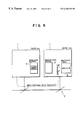
- FIG. 9 is a block diagram showing a principal portion of the communication network system according to this embodiment for explaining a method to be taken in the case of no notification of data transmission cancel;
- FIG. 10 is a block diagram showing a principal portion of a common communication network system for explaining a PUT command and a GET command.
- FIG. 11 is a block diagram showing a principal portion of a common communication network system for explaining a communication method based upon a SEND-GET.
- a PUT command or a GET command is put to use for the data copy (memory copy) between nodes through the communication network.
- a node #N forwards the data at an address XXX in a memory 100 -N to a node #M, the PUT command (data send command) is issued from the node #N to the node #M. That is, in a manner that the node #N designates an ID (in this example, M) of the data receiving node #M being the destination of the data and a data-copied address YYY in a memory 100 -M of the node #M and issues the PUT command, the data laying at the address XXX in the memory 100 -N of the node #N transferred and copied through a communication network 200 into the address YYY in the memory 100 -M of the node #M.
- M an ID
- M data-copied address YYY in a memory 100 -M of the node #M
- the GET command (data get command) is issued from the node #N to the node #M. That is, in a manner that the node #N designates an ID (in this example, M) of the node #M retaining the target data and the address WWW designating the target data and issue the GET command, the data existing at the address WWW in the memory 100 -M of the node #M is copied through the communication network 200 into an address ZZZ in the memory 100 -N of the node #N.
- the aforesaid GET command is used in the form of a combination with a SEND message as shown in FIG. 11, and a communication mode based upon this combination is called SEND-GET.
- the SEND message data send message
- the SEND message is used when the data of a data transmitting node is forwarded to a receive buffer defined in advance by a data receiving node.
- the SEND message retaining the address XXX of the transmission data on the memory (SEND DATA BUFFER) 100 -N and the size S of that data is transmitted from the data transmitting node #N to the data receiving node #M.
- the SEND message taken from the node #N through the communication network 200 is once stored in a receive buffer (not shown). Subsequently, after the contents of the SEND message are deciphered or decoded in a communication driver (not shown), a data write area according to the size S is secured on the memory (GET DATA BUFFER) 100 -M, before the GET command is issued to the node #N so that the data at the address XXX in the memory 100 -N is forwarded to the node #M. The data sent from the node #N through the communication network 200 in response to this GET command is written into the area of the designated address (the aforesaid data write area) in the memory 100 -M of the node #M.
- the data transmitting node can designate an arbitrary address in a memory to directly transmit data to that address, thus enabling the effective execution of data copy between nodes to enhance the communication performance and, further, facilitating the buffer management in each of the nodes.
- This invention is for developing and establishing a method of realizing a multicast function by utilizing the existing basic communication function issuing a SEND message, a GET command and a PUT command, and this method can minimize the traffic in the whole communication network concurrently with maintaining the independence of each of the nodes.
- FIG. 2 is a block diagram showing an arrangement of a communication network system to which a multicast transmission method according to the embodiment of this invention is applied, and is also an illustration available for explaining an operation of this communication network system.
- a plurality of nodes 1 (# 0 to #N) are connected through a communication network (for example, AP-Net) 2 using, for example, TCP/IP to each other to be communicable mutually.
- AP-Net for example, AP-Net
- Each of the nodes 1 is equipped with a communication driver (data link driver; for example, AP-Net driver) la for directly giving and taking signals to/from the communication network 2 to accomplish the transmission/reception of data.
- a communication driver data link driver; for example, AP-Net driver
- This communication driver 1 a is employed as a basic communication function (which will sometimes be referred hereinafter to as a communication primitive) including a function (including a communication mode based on SEND-GET) to issue and send the SEND message, the GET command and the PUT command mentioned before with reference to FIGS. 10 and 11.
- a basic communication function which will sometimes be referred hereinafter to as a communication primitive
- a function including a communication mode based on SEND-GET
- the SEND message (data send message) is for transmitting data to a receive buffer defined in advance by the data transmitting node
- the GET command (data get command) is for designating data in a memory (send data buffer 4 which will be described herein later) of a given node to make a request for the transmission of that data to the corresponding node
- the PUT command (data send command) is for designating a memory address in a receiving (destination) node and for transmitting data.
- each of the nodes 1 is provided with a multicast table 3 , a send (transmission) data buffer 4 , a receive/get (acquisition) data buffer 5 and a multicast transmission table 6 .
- a data transmitting node 1 is shown as a node #n while one of data receiving nodes 1 pertaining to a multicast group is shown as a node #m, and only components needed at the transmission in each mode are illustrated in the node #n while only components necessary at the reception in each mode are illustrated in the node #m.
- the communication driver 1 a of the nodes 1 are omitted from the illustration.
- the multicast table 3 is made in such a manner that, when a node 1 possessing this multicast table 3 belongs to a multicast group (specific group), a multicast address (group address) of the group it belongs to is set and registered beforehand.
- a multicast address group address
- IP addresses each comprising 32 bits
- an address whose leading four bits is “1110” is recognized as a multicast address. That is, the range of 224.0.0.0 to 239.255.255.255 is made to be allocated to the multicast addresses.
- the send data buffer (memory) 4 stores data (for example, multicast data) to be transmitted, while the receive/get data buffer (memory) 5 stores data received or acquired from a data transmitting node.
- the multicast transmission table 6 is made in such a manner that a flag (YES/NO) for recognizing a node (data receiving node) which is the target of the multicast transmission is set at every node 1 other than its own node, with that flag being set by a PUT command or a SEND message from a data receiving node as will be mentioned later.
- the multicast table 3 , the send data buffer 4 , the receive/get data buffer 5 and the multicast transmission table 6 are incorporated into or provided in association with the communication driver 1 a of each of the node 1 .
- FIGS. 1 to 9 a description will be given hereinbelow of a multicast transmission method for use in the communication network system thus arranged according to this embodiment.
- the description will start with a basic procedure of the multicast transmission method according to this embodiment, that is, a basic operation for the multicast transmission by the communication driver la of each of the nodes 1 , with reference to the flow charts shown in FIGS. 1A and 1B in view of FIG. 2 .
- FIG. 1A is a flow chart (steps S 0 to S 3 and S 31 ) available for describing a basic transmission processing procedure to be conducted in each of the nodes 1 .
- the communication driver 1 a of each of the nodes 1 always decides whether a transmission request occurs or not (step S 0 ), and if it occurs (YES route from step S 0 ), checks whether or not the transmission request signifies a multicast transmission request (step S 1 ).
- the communication driver 1 a When receiving the multicast transmission request (YES route from step S 1 ), the communication driver 1 a adds a multicast address corresponding to that multicast transmission request to a SEND message and broadcasts the SEND message plus multicast address to all the nodes 1 (step S 2 ; see a thin solid line drawn arrow A 1 “SEND MESSAGE WITH MULTICAST ADDRESS” in FIG. 2 ). At this time, the data volume of the SEND message with the multicast address is considerably small, with the result that the traffic on the communication network 2 hardly undergoes the influence of the broadcast of the SEND message.
- the communication driver 1 a transmits multicast data to the node (node pertaining to a multicast group; data receiving node) 1 which issues the request for the data transmission in response to the broadcasted SEND message (step S 3 ).
- step S 31 the communication driver 1 a conducts the transmission processing in answer to that transmission request (step S 31 ).
- FIG. 1B is a flow chart (steps S 32 , S 4 to S 7 and S 41 ) useful for explaining a basic transmission processing procedure to be done in each of the nodes 1 .
- the communication driver la of each of the nodes 1 always decides whether data arrives (is received) or not (step S 32 ), and if the data comes (YES route from step S 32 ), checks whether or not that data is a SEND message with a multicast address (step S 4 ).
- the communication driver la refers to the multicast table 3 (see FIGS. 3 to 9 ) to compare the multicast address added to the SEND message it receives with a set address within the multicast table 3 for deciding whether or not that multicast address exists within the multicast table 3 (step S 5 ).
- the communication driver 1 a issues a request for the transmission of multicast data (data responding to a multicast transmission request a data transmitting node issues) to a data transmitting node transmitting the SEND message through the use of a communication primitive (the generation and delivery of a GET command, a SEND message or a PUT command) (see a dotted line drawn arrow A 2 “REQUEST MULTICAST DATA” to make the data transmitting node transmit the data to its own node (step S 6 ).
- a communication primitive the generation and delivery of a GET command, a SEND message or a PUT command
- the communication driver 1 a informs the data transmitting node transmitting the SEND message of the fact that the transmission of the multicast data is unnecessary, through the use of the communication primitive (the generation and delivery of a PUT command, a GET command or a SEND message) (step S 7 ; see a dashed line drawn arrow A 3 “CANCEL MULITICAST DATA”.
- the data transmission cancel notifying method using the communication primitive (a PUT command, a GET command or a SEND message) in this step S 7 will be described herein later with reference to FIGS. 6 to 8 .
- the communication driver la can also immediately terminate its processing without informing of no need for the data transmission.
- the step S 7 is omissible.
- step S 4 determines whether the reception data is not the SEND message with the multicast address (NO route from step S 4 ). If the decision of the step S 4 indicates that the reception data is not the SEND message with the multicast address (NO route from step S 4 ), the communication driver la pertinently processes the data it receives in accordance with its contents (step S 41 ).
- a data transmitting node # 0 in which a multicast transmission request occurs adds a multicast address to a SEND message and broadcasts the SEND message plus multicast address to nodes # 1 to #N through the processing of the step S 2 in FIG. 1 A.
- the node # 1 in which the multicast address exists within its multicast table 3 makes a request for the transmission of the corresponding multicast data toward the data transmitting node # 0 by the use of a communication primitive (a GET command, a SEND message or a PUT command) through the processing of the step S 6 in FIG. 1B as indicated by the dotted line drawn arrow A 2 , so that the data transmitting node # 0 forwards the multicast data to the node # 1 .
- a communication primitive a GET command, a SEND message or a PUT command
- the node # 2 or #N in which the multicast address does not exist within its multicast table 3 informs the data transmitting node # 0 of the fact of no need for the transmission of the multicast data by the use of a communication primitive (a PUT command, a GET command or a SEND message) through the processing of the step S 7 in FIG. 1B as indicated by the dashed line drawn arrow A 3 .
- a communication primitive a PUT command, a GET command or a SEND message
- FIGS. 3 to 5 a description will be made hereinbelow of data transmission request methods (the processing of the step S 6 in FIG. 1B) using a GET command, a SEND message or a PUT command which constitutes a communication primitive.
- a data transmitting node #n attaches a multicast address, for example, “224.0.0.2” to a SEND message to broadcast the SEND message plus multicast address and this address “224.0.0.2” exists within the multicast table 3 of a node #m.
- the node #m issues a GET command toward the data transmitting node #n to make a request for the transmission of multicast data, so that the communication driver 1 a (see FIG. 2) causes the multicast data in the send data buffer 4 of the data transmitting node #n to be forwarded through the communication network 2 to the node #m and to be put at a designated address in the receive/get data buffer 5 of the node #m.
- the node #m sends a SEND message with a multicast data transmission request (“REQUEST MULTICAST DATA” to the data transmitting node #n to make a request for the transmission of multicast data thereto, whereupon the communication driver 1 a (see FIG. 2 ), after deciphering that message, causes the multicast data in the send data buffer 4 of the data transmitting node #n to be forwarded through the communication network 2 to the node #m.
- a multicast data transmission request (“REQUEST MULTICAST DATA”
- the node #m issues a PUT command to the data transmitting node #n for making a request for the transmission of the multicast data, whereupon “YES” (flag ON) is put in a column pertinent to the node #m in the multicast transmission table 6 of the data transmitting node #n.
- the communication driver la see FIG. 2 of the data transmitting node #n transmits the multicast data in the send data buffer 4 through the communication network 2 to the node #m.
- the data transmitting node 1 which broadcasts a SEND message with a multicast address, expects the response from all the nodes 1 forming the broadcasting targets.
- the node(s) 1 in which the multicast address does not exist within its multicast table 3 also informs the data transmitting node 1 of the fact that the transmission of the multicast data is unnecessary through the use of a PUT command, a GET command or a SEND message.
- the node #m issues a PUT command to the data transmitting node #n to inform it of the fact that the transmission of the multicast data is unnecessary so that “NO” (flag OFF) is placed in a column for the node #m in the multicast transmission table 6 of the data transmitting node #n.
- the communication driver la (see FIG. 2) of the data transmitting node #n refers to the multicast transmission table 6 , and if the flag of the node #m is the OFF state, inhibits the transmission of the multicast data to the node #m.
- the node #m issues a GET command to the data transmitting node #n to inform it of the fact that the transmission of the multicast data is unnecessary (the information is made through the updating of a GET command completion flag) so that “NO” (flag OFF) is placed in a column for the node #m in the multicast transmission table 6 of the data transmitting node #n.
- the communication driver 1 a (see FIG. 2) of the data transmitting node #n refers to the multicast transmission table 6 , and if the flag of the node #m is the OFF state, inhibits the transmission of the multicast data to the node #m.
- the node #m issues a SEND message with multicast data transmission non-requirement information (“CANCEL MULTICAST DATA”) to the data transmitting node #n to inform it of the fact that the transmission of the multicast data is unnecessary.
- the communication driver 1 a (see FIG. 2 ), decoding that message, does not transmit the multicast data to the node #m.
- a data transmitting node 1 in which a multicast transmission request occurs adds a multicast address to a SEND message and broadcasts the SEND message plus multicast address toward all the nodes, and only the node(s) 1 having a previously set address coincident with the multicast address issues and sends a GET command, a SEND message or a PUT command to actively make a request for the transmission of the multicast data to the data transmitting node 1 , and therefore, the multicast data transmission is achieved in one-to-one relation between the data transmitting node 1 and each of the nodes being the target of the multicast transmission.
- the broadcast of the SEND message hardly affects the traffic on the communication network 2 as mentioned before, it is possible to realize a multicast function among the nodes 1 while minimizing the traffic on the communication network 2 .
- this invention is applied to a communication network based upon TCP/IP, this invention is not limited to this, but is likewise applicable to any communication network employing a protocol defining a SEND message, a GET command and a PUT command, and in this case, the same effects are obtainable.
Abstract
Description
Claims (8)
Applications Claiming Priority (4)
| Application Number | Priority Date | Filing Date | Title |
|---|---|---|---|
| JP9-299704 | 1997-10-31 | ||
| JP29970497 | 1997-10-31 | ||
| JP10-261580 | 1998-09-16 | ||
| JP26158098A JP3493309B2 (en) | 1997-10-31 | 1998-09-16 | Multicast transmission method |
Publications (1)
| Publication Number | Publication Date |
|---|---|
| US6330238B1 true US6330238B1 (en) | 2001-12-11 |
Family
ID=26545143
Family Applications (1)
| Application Number | Title | Priority Date | Filing Date |
|---|---|---|---|
| US09/168,857 Expired - Lifetime US6330238B1 (en) | 1997-10-31 | 1998-10-09 | Multicast transmission method |
Country Status (4)
| Country | Link |
|---|---|
| US (1) | US6330238B1 (en) |
| EP (1) | EP0921655B1 (en) |
| JP (1) | JP3493309B2 (en) |
| DE (1) | DE69829630T2 (en) |
Cited By (18)
| Publication number | Priority date | Publication date | Assignee | Title |
|---|---|---|---|---|
| US20010039590A1 (en) * | 2000-03-30 | 2001-11-08 | Akihiro Furukawa | Device and method for using MAC address of networked devices to set IP addresses |
| US6526054B1 (en) * | 1999-06-28 | 2003-02-25 | Nortel Networks Limited | System, device, and method for transitioning from DVMRP to BGMP for interdomain multicast routing over the internet multicast backbone |
| US6801529B1 (en) * | 1999-06-08 | 2004-10-05 | Amx Corporation | Method and system for sending messages to multiple locations in a control system |
| WO2005091562A1 (en) * | 2004-03-24 | 2005-09-29 | Huawei Technologies Co., Ltd. | A method for realizing the multicast service |
| US20050232272A1 (en) * | 1999-04-14 | 2005-10-20 | Verizon Laboratories Inc. | Data link layer switch with multicast capability |
| US20060221866A1 (en) * | 2005-04-01 | 2006-10-05 | Shepherd Gregory J | Data driven route advertisement |
| US20060268871A1 (en) * | 2005-01-26 | 2006-11-30 | Erik Van Zijst | Layered multicast and fair bandwidth allocation and packet prioritization |
| US20070127472A1 (en) * | 2004-02-05 | 2007-06-07 | Matsushita Electric Industrial Co., Ltd. | Broadcast data communicating method, broadcast data receiving terminal, and broadcast data transmitting server |
| US20070159966A1 (en) * | 2005-12-29 | 2007-07-12 | Sumner Devon S | Systems and methods for managing traffic within a peer-to-peer network |
| US20070175785A1 (en) * | 2006-01-28 | 2007-08-02 | Darren Sharp | Accessory bit caddie base marketing cover |
| US20070274246A1 (en) * | 2006-05-26 | 2007-11-29 | Stephens Adrian P | Reliable multicast in a network having a power saving protocol |
| US20090274042A1 (en) * | 2008-04-30 | 2009-11-05 | Cisco Technology, Inc. | Network based switchover to original content after ad-insertion device failure |
| US7673030B2 (en) | 1999-04-29 | 2010-03-02 | Amx Llc | Internet control system communication protocol, method and computer program |
| US7917576B1 (en) * | 2000-12-14 | 2011-03-29 | At&T Intellectual Property I, L.P. | System and method for sending electronic mail in a client-server architecture |
| CN102801622A (en) * | 2012-08-14 | 2012-11-28 | 神州数码网络(北京)有限公司 | Transmitting method and device for data messages |
| US8892711B2 (en) | 2009-04-30 | 2014-11-18 | Zte Corporation | Method for acquiring node information, and client and server |
| US9063739B2 (en) | 2005-09-07 | 2015-06-23 | Open Invention Network, Llc | Method and computer program for device configuration |
| CN111835881A (en) * | 2020-06-24 | 2020-10-27 | 珠海中慧微电子有限公司 | Beacon signaling protocol design method for broadband carrier communication network |
Families Citing this family (3)
| Publication number | Priority date | Publication date | Assignee | Title |
|---|---|---|---|---|
| GB2367989B (en) * | 1999-07-12 | 2004-04-07 | Fujitsu Ltd | Communication system, method of processing message in communication system, and station-side unit and subscriber-side unit |
| US7203720B2 (en) * | 2002-11-27 | 2007-04-10 | Bea Systems, Inc. | Web server hit multiplier and redirector |
| EP1668527A4 (en) * | 2003-09-22 | 2010-02-24 | Transeam Technologies | Group-to-group communication over a single connection and fault tolerant symmetric multi-computing system |
Citations (11)
| Publication number | Priority date | Publication date | Assignee | Title |
|---|---|---|---|---|
| JPH02133856A (en) | 1988-11-14 | 1990-05-23 | Toshiba Corp | Data transfer device |
| JPH02503121A (en) | 1987-10-06 | 1990-09-27 | ベル、コミュニケーションズ、リサーチ、インコーポレーテッド | Selective receiver for each processor in a multiple processor system |
| JPH02297656A (en) | 1989-05-11 | 1990-12-10 | Mitsubishi Electric Corp | Data control system |
| JPH05324545A (en) | 1992-05-15 | 1993-12-07 | Toshiba Corp | Bus controller |
| US5361256A (en) * | 1992-11-27 | 1994-11-01 | International Business Machines Corporation | Inter-domain multicast routing |
| US5444702A (en) | 1992-09-14 | 1995-08-22 | Network Equipment Technologies, Inc. | Virtual network using asynchronous transfer mode |
| US5457683A (en) | 1993-05-07 | 1995-10-10 | Apple Computer, Inc. | Link and discovery protocols for a ring interconnect architecture |
| US5511168A (en) * | 1993-07-01 | 1996-04-23 | Digital Equipment Corporation | Virtual circuit manager for multicast messaging |
| US5898686A (en) * | 1995-04-25 | 1999-04-27 | Cabletron Systems, Inc. | Network bridge with multicast forwarding table |
| US5940391A (en) * | 1997-11-25 | 1999-08-17 | International Business Machines Corporation | Method and apparatus for reconfigurable and adaptive stream multicast |
| US6181697B1 (en) * | 1998-03-31 | 2001-01-30 | At&T Corp. | Method for a unicast endpoint client to access a multicast internet protocol (IP) session and to serve as a redistributor of such session |
-
1998
- 1998-09-16 JP JP26158098A patent/JP3493309B2/en not_active Expired - Lifetime
- 1998-10-09 US US09/168,857 patent/US6330238B1/en not_active Expired - Lifetime
- 1998-10-16 DE DE1998629630 patent/DE69829630T2/en not_active Expired - Lifetime
- 1998-10-16 EP EP19980308494 patent/EP0921655B1/en not_active Expired - Lifetime
Patent Citations (11)
| Publication number | Priority date | Publication date | Assignee | Title |
|---|---|---|---|---|
| JPH02503121A (en) | 1987-10-06 | 1990-09-27 | ベル、コミュニケーションズ、リサーチ、インコーポレーテッド | Selective receiver for each processor in a multiple processor system |
| JPH02133856A (en) | 1988-11-14 | 1990-05-23 | Toshiba Corp | Data transfer device |
| JPH02297656A (en) | 1989-05-11 | 1990-12-10 | Mitsubishi Electric Corp | Data control system |
| JPH05324545A (en) | 1992-05-15 | 1993-12-07 | Toshiba Corp | Bus controller |
| US5444702A (en) | 1992-09-14 | 1995-08-22 | Network Equipment Technologies, Inc. | Virtual network using asynchronous transfer mode |
| US5361256A (en) * | 1992-11-27 | 1994-11-01 | International Business Machines Corporation | Inter-domain multicast routing |
| US5457683A (en) | 1993-05-07 | 1995-10-10 | Apple Computer, Inc. | Link and discovery protocols for a ring interconnect architecture |
| US5511168A (en) * | 1993-07-01 | 1996-04-23 | Digital Equipment Corporation | Virtual circuit manager for multicast messaging |
| US5898686A (en) * | 1995-04-25 | 1999-04-27 | Cabletron Systems, Inc. | Network bridge with multicast forwarding table |
| US5940391A (en) * | 1997-11-25 | 1999-08-17 | International Business Machines Corporation | Method and apparatus for reconfigurable and adaptive stream multicast |
| US6181697B1 (en) * | 1998-03-31 | 2001-01-30 | At&T Corp. | Method for a unicast endpoint client to access a multicast internet protocol (IP) session and to serve as a redistributor of such session |
Cited By (40)
| Publication number | Priority date | Publication date | Assignee | Title |
|---|---|---|---|---|
| US20050232272A1 (en) * | 1999-04-14 | 2005-10-20 | Verizon Laboratories Inc. | Data link layer switch with multicast capability |
| US7573874B2 (en) * | 1999-04-14 | 2009-08-11 | Verizon Laboratories Inc. | Data link layer switch with multicast capability |
| US8572224B2 (en) | 1999-04-29 | 2013-10-29 | Thomas D. Hite | Internet control system communication protocol, method and computer program |
| US7673030B2 (en) | 1999-04-29 | 2010-03-02 | Amx Llc | Internet control system communication protocol, method and computer program |
| US6801529B1 (en) * | 1999-06-08 | 2004-10-05 | Amx Corporation | Method and system for sending messages to multiple locations in a control system |
| US6526054B1 (en) * | 1999-06-28 | 2003-02-25 | Nortel Networks Limited | System, device, and method for transitioning from DVMRP to BGMP for interdomain multicast routing over the internet multicast backbone |
| US20010039590A1 (en) * | 2000-03-30 | 2001-11-08 | Akihiro Furukawa | Device and method for using MAC address of networked devices to set IP addresses |
| US7406513B2 (en) | 2000-03-30 | 2008-07-29 | Brother Kogyo Kabushiki Kaisha | Device and method for using MAC address of networked devices to set IP addresses |
| US7917576B1 (en) * | 2000-12-14 | 2011-03-29 | At&T Intellectual Property I, L.P. | System and method for sending electronic mail in a client-server architecture |
| US20070127472A1 (en) * | 2004-02-05 | 2007-06-07 | Matsushita Electric Industrial Co., Ltd. | Broadcast data communicating method, broadcast data receiving terminal, and broadcast data transmitting server |
| US7830825B2 (en) * | 2004-03-24 | 2010-11-09 | Huawei Technologies Co., Ltd. | Method for realizing the multicast service |
| US20070253409A1 (en) * | 2004-03-24 | 2007-11-01 | Huawei Technologies Co., Ltd. | Method for Realizing the Multicast Service |
| WO2005091562A1 (en) * | 2004-03-24 | 2005-09-29 | Huawei Technologies Co., Ltd. | A method for realizing the multicast service |
| US7733868B2 (en) | 2005-01-26 | 2010-06-08 | Internet Broadcasting Corp. | Layered multicast and fair bandwidth allocation and packet prioritization |
| US20090257448A1 (en) * | 2005-01-26 | 2009-10-15 | Internet Broadcasting Corporation | Layered multicast and fair bandwidth allocation and packet prioritization |
| US11910037B2 (en) | 2005-01-26 | 2024-02-20 | Scale Video Coding, Llc | Layered multicast and fair bandwidth allocation and packet prioritization |
| US20090296708A1 (en) * | 2005-01-26 | 2009-12-03 | Internet Broadcasting Corporation | Layered multicast and fair bandwidth allocation and packet prioritization |
| US20090303997A1 (en) * | 2005-01-26 | 2009-12-10 | Internet Broadcasting Corporation | Layered multicast and fair bandwidth allocation and packet prioritization |
| US11019372B2 (en) | 2005-01-26 | 2021-05-25 | Blitz Data Systems, Llc | Layered multicast and fair bandwidth allocation and packet prioritization |
| US9503763B2 (en) | 2005-01-26 | 2016-11-22 | Blitz Stream Video, Llc | Layered multicast and fair bandwidth allocation and packet prioritization |
| US9462305B2 (en) | 2005-01-26 | 2016-10-04 | Blitz Stream Video, Llc | Layered multicast and fair bandwidth allocation and packet prioritization |
| US9438938B2 (en) | 2005-01-26 | 2016-09-06 | Biltz Stream Video, LLC | Layered multicast and fair bandwidth allocation and packet prioritization |
| US20060268871A1 (en) * | 2005-01-26 | 2006-11-30 | Erik Van Zijst | Layered multicast and fair bandwidth allocation and packet prioritization |
| US9414094B2 (en) | 2005-01-26 | 2016-08-09 | Blitz Stream Video, Llc | Layered multicast and fair bandwidth allocation and packet prioritization |
| US8958426B2 (en) | 2005-01-26 | 2015-02-17 | Blitz Stream Video, Llc | Layered multicast and fair bandwidth allocation and packet prioritization |
| US8514718B2 (en) | 2005-01-26 | 2013-08-20 | Blitz Stream Video, Llc | Layered multicast and fair bandwidth allocation and packet prioritization |
| US20060221866A1 (en) * | 2005-04-01 | 2006-10-05 | Shepherd Gregory J | Data driven route advertisement |
| US8085755B2 (en) * | 2005-04-01 | 2011-12-27 | Cisco Technology, Inc. | Data driven route advertisement |
| US9063739B2 (en) | 2005-09-07 | 2015-06-23 | Open Invention Network, Llc | Method and computer program for device configuration |
| US20070159966A1 (en) * | 2005-12-29 | 2007-07-12 | Sumner Devon S | Systems and methods for managing traffic within a peer-to-peer network |
| US7680044B2 (en) * | 2005-12-29 | 2010-03-16 | Panasonic Electric Works Co., Ltd. | Systems and methods for managing traffic within a peer-to-peer network |
| US20070175785A1 (en) * | 2006-01-28 | 2007-08-02 | Darren Sharp | Accessory bit caddie base marketing cover |
| US20070274246A1 (en) * | 2006-05-26 | 2007-11-29 | Stephens Adrian P | Reliable multicast in a network having a power saving protocol |
| US8675478B2 (en) | 2008-04-30 | 2014-03-18 | Cisco Technology, Inc. | Network based switchover to original content after ad-insertion device failure |
| US20090274042A1 (en) * | 2008-04-30 | 2009-11-05 | Cisco Technology, Inc. | Network based switchover to original content after ad-insertion device failure |
| US8892711B2 (en) | 2009-04-30 | 2014-11-18 | Zte Corporation | Method for acquiring node information, and client and server |
| CN102801622A (en) * | 2012-08-14 | 2012-11-28 | 神州数码网络(北京)有限公司 | Transmitting method and device for data messages |
| CN102801622B (en) * | 2012-08-14 | 2016-02-24 | 神州数码网络(北京)有限公司 | A kind of retransmission method of data message and retransmission unit |
| CN111835881A (en) * | 2020-06-24 | 2020-10-27 | 珠海中慧微电子有限公司 | Beacon signaling protocol design method for broadband carrier communication network |
| CN111835881B (en) * | 2020-06-24 | 2022-07-12 | 珠海中慧微电子有限公司 | Beacon signaling protocol design method for broadband carrier communication network |
Also Published As
| Publication number | Publication date |
|---|---|
| JPH11196112A (en) | 1999-07-21 |
| JP3493309B2 (en) | 2004-02-03 |
| DE69829630T2 (en) | 2005-09-29 |
| EP0921655A2 (en) | 1999-06-09 |
| EP0921655B1 (en) | 2005-04-06 |
| DE69829630D1 (en) | 2005-05-12 |
| EP0921655A3 (en) | 1999-06-16 |
Similar Documents
| Publication | Publication Date | Title |
|---|---|---|
| US6330238B1 (en) | Multicast transmission method | |
| US7321592B2 (en) | Method of and apparatus for implementing and sending an asynchronous control mechanism packet used to control bridge devices within a network of IEEE Std 1394 serial buses | |
| JP2786121B2 (en) | LAN connection router | |
| JP3266188B2 (en) | Multicast communication device and multicast communication method | |
| US6128294A (en) | Network connecting apparatus | |
| JPH10242962A (en) | Multi-cast gateway communication method and system on internet | |
| JP2806466B2 (en) | Data transmission control method | |
| US6625658B1 (en) | End equipment and router | |
| US20090003295A1 (en) | Ad-hoc network device with reduced data loss | |
| KR20040007303A (en) | Broadcast type communication data distribution device and broadcast type communication system | |
| US7586913B2 (en) | Mobile IP packet communication system | |
| US6295560B1 (en) | Data delivery system with load distribution among data delivery units using shared lower address and unique lower layer address | |
| JP2005341199A (en) | Dhcp packet congestion control system and method therefor | |
| JPS61131940A (en) | Packet transfer system | |
| JP3398844B2 (en) | Transfer packet receiver | |
| JP3291712B2 (en) | Global address resolution processing method | |
| KR100264349B1 (en) | How to handle B.U.S in LAN emulation | |
| JP3425384B2 (en) | Data delivery system and method, and data delivery unit | |
| JPH0362255A (en) | Data transmission system | |
| JPH06216916A (en) | Lan control system | |
| JP3423618B2 (en) | LAN connection device and LAN connection system | |
| JPH0969857A (en) | Lan connection system | |
| JPS5816823B2 (en) | Communication method | |
| US20050129048A1 (en) | Method for transmitting multicast data information | |
| JPH09284339A (en) | Multi-cast communication system |
Legal Events
| Date | Code | Title | Description |
|---|---|---|---|
| AS | Assignment |
Owner name: FUJITSU LIMITED, JAPAN Free format text: ASSIGNMENT OF ASSIGNORS INTEREST;ASSIGNOR:OOE, KAZUICHI;REEL/FRAME:009511/0297 Effective date: 19981002 |
|
| STCF | Information on status: patent grant |
Free format text: PATENTED CASE |
|
| FPAY | Fee payment |
Year of fee payment: 4 |
|
| AS | Assignment |
Owner name: DOSA ADVANCES LLC, NEVADA Free format text: ASSIGNMENT OF ASSIGNORS INTEREST;ASSIGNOR:FUJITSU LIMITED;REEL/FRAME:016745/0196 Effective date: 20050331 |
|
| FEPP | Fee payment procedure |
Free format text: PAYER NUMBER DE-ASSIGNED (ORIGINAL EVENT CODE: RMPN); ENTITY STATUS OF PATENT OWNER: LARGE ENTITY Free format text: PAYOR NUMBER ASSIGNED (ORIGINAL EVENT CODE: ASPN); ENTITY STATUS OF PATENT OWNER: LARGE ENTITY |
|
| FPAY | Fee payment |
Year of fee payment: 8 |
|
| FPAY | Fee payment |
Year of fee payment: 12 |
|
| AS | Assignment |
Owner name: XYLON LLC, DELAWARE Free format text: MERGER;ASSIGNOR:DOSA ADVANCES LLC;REEL/FRAME:036942/0495 Effective date: 20150813 |
|
| AS | Assignment |
Owner name: HANGER SOLUTIONS, LLC, GEORGIA Free format text: ASSIGNMENT OF ASSIGNORS INTEREST;ASSIGNOR:INTELLECTUAL VENTURES ASSETS 161 LLC;REEL/FRAME:052159/0509 Effective date: 20191206 |