US6281970B1 - Airborne IR fire surveillance system providing firespot geopositioning - Google Patents
Airborne IR fire surveillance system providing firespot geopositioning Download PDFInfo
- Publication number
- US6281970B1 US6281970B1 US09/267,513 US26751399A US6281970B1 US 6281970 B1 US6281970 B1 US 6281970B1 US 26751399 A US26751399 A US 26751399A US 6281970 B1 US6281970 B1 US 6281970B1
- Authority
- US
- United States
- Prior art keywords
- pod
- aircraft
- ground station
- borne system
- emitting source
- Prior art date
- Legal status (The legal status is an assumption and is not a legal conclusion. Google has not performed a legal analysis and makes no representation as to the accuracy of the status listed.)
- Expired - Lifetime
Links
- 238000005259 measurement Methods 0.000 claims abstract description 5
- 230000005540 biological transmission Effects 0.000 claims abstract description 3
- 239000013598 vector Substances 0.000 claims description 38
- 238000004891 communication Methods 0.000 claims description 15
- 230000003287 optical effect Effects 0.000 claims description 5
- 238000001228 spectrum Methods 0.000 claims description 3
- 238000001444 catalytic combustion detection Methods 0.000 claims 2
- 238000011045 prefiltration Methods 0.000 claims 1
- 230000001960 triggered effect Effects 0.000 claims 1
- 238000001514 detection method Methods 0.000 abstract description 8
- 238000000034 method Methods 0.000 abstract description 6
- 230000008569 process Effects 0.000 abstract description 3
- 239000011159 matrix material Substances 0.000 description 8
- 238000012545 processing Methods 0.000 description 6
- 230000000007 visual effect Effects 0.000 description 6
- 238000010586 diagram Methods 0.000 description 5
- 238000013459 approach Methods 0.000 description 4
- 230000008859 change Effects 0.000 description 3
- 238000001816 cooling Methods 0.000 description 3
- 230000006870 function Effects 0.000 description 3
- 230000004044 response Effects 0.000 description 3
- 230000003595 spectral effect Effects 0.000 description 3
- 230000009466 transformation Effects 0.000 description 3
- 208000001836 Firesetting Behavior Diseases 0.000 description 2
- 241000565630 Podaxis Species 0.000 description 2
- 230000014509 gene expression Effects 0.000 description 2
- 238000003384 imaging method Methods 0.000 description 2
- 238000010926 purge Methods 0.000 description 2
- 230000005855 radiation Effects 0.000 description 2
- 229910000661 Mercury cadmium telluride Inorganic materials 0.000 description 1
- LKJPSUCKSLORMF-UHFFFAOYSA-N Monolinuron Chemical compound CON(C)C(=O)NC1=CC=C(Cl)C=C1 LKJPSUCKSLORMF-UHFFFAOYSA-N 0.000 description 1
- 210000001015 abdomen Anatomy 0.000 description 1
- 230000009471 action Effects 0.000 description 1
- 238000003491 array Methods 0.000 description 1
- 230000003190 augmentative effect Effects 0.000 description 1
- 230000008901 benefit Effects 0.000 description 1
- 230000001413 cellular effect Effects 0.000 description 1
- 238000012512 characterization method Methods 0.000 description 1
- 238000010276 construction Methods 0.000 description 1
- 230000003111 delayed effect Effects 0.000 description 1
- 230000000694 effects Effects 0.000 description 1
- 238000011156 evaluation Methods 0.000 description 1
- 231100001261 hazardous Toxicity 0.000 description 1
- WPYVAWXEWQSOGY-UHFFFAOYSA-N indium antimonide Chemical compound [Sb]#[In] WPYVAWXEWQSOGY-UHFFFAOYSA-N 0.000 description 1
- 230000010354 integration Effects 0.000 description 1
- 238000012986 modification Methods 0.000 description 1
- 230000004048 modification Effects 0.000 description 1
- 238000012544 monitoring process Methods 0.000 description 1
- 238000010606 normalization Methods 0.000 description 1
- 238000005192 partition Methods 0.000 description 1
- 230000002265 prevention Effects 0.000 description 1
- 238000011160 research Methods 0.000 description 1
- 230000035945 sensitivity Effects 0.000 description 1
- 239000007787 solid Substances 0.000 description 1
- 230000007480 spreading Effects 0.000 description 1
- 230000001629 suppression Effects 0.000 description 1
- 238000010408 sweeping Methods 0.000 description 1
- 230000009897 systematic effect Effects 0.000 description 1
- 238000000844 transformation Methods 0.000 description 1
Images


Classifications
-
- G—PHYSICS
- G01—MEASURING; TESTING
- G01S—RADIO DIRECTION-FINDING; RADIO NAVIGATION; DETERMINING DISTANCE OR VELOCITY BY USE OF RADIO WAVES; LOCATING OR PRESENCE-DETECTING BY USE OF THE REFLECTION OR RERADIATION OF RADIO WAVES; ANALOGOUS ARRANGEMENTS USING OTHER WAVES
- G01S19/00—Satellite radio beacon positioning systems; Determining position, velocity or attitude using signals transmitted by such systems
- G01S19/38—Determining a navigation solution using signals transmitted by a satellite radio beacon positioning system
- G01S19/39—Determining a navigation solution using signals transmitted by a satellite radio beacon positioning system the satellite radio beacon positioning system transmitting time-stamped messages, e.g. GPS [Global Positioning System], GLONASS [Global Orbiting Navigation Satellite System] or GALILEO
- G01S19/42—Determining position
- G01S19/51—Relative positioning
-
- G—PHYSICS
- G01—MEASURING; TESTING
- G01S—RADIO DIRECTION-FINDING; RADIO NAVIGATION; DETERMINING DISTANCE OR VELOCITY BY USE OF RADIO WAVES; LOCATING OR PRESENCE-DETECTING BY USE OF THE REFLECTION OR RERADIATION OF RADIO WAVES; ANALOGOUS ARRANGEMENTS USING OTHER WAVES
- G01S19/00—Satellite radio beacon positioning systems; Determining position, velocity or attitude using signals transmitted by such systems
- G01S19/38—Determining a navigation solution using signals transmitted by a satellite radio beacon positioning system
- G01S19/39—Determining a navigation solution using signals transmitted by a satellite radio beacon positioning system the satellite radio beacon positioning system transmitting time-stamped messages, e.g. GPS [Global Positioning System], GLONASS [Global Orbiting Navigation Satellite System] or GALILEO
- G01S19/53—Determining attitude
-
- G—PHYSICS
- G01—MEASURING; TESTING
- G01S—RADIO DIRECTION-FINDING; RADIO NAVIGATION; DETERMINING DISTANCE OR VELOCITY BY USE OF RADIO WAVES; LOCATING OR PRESENCE-DETECTING BY USE OF THE REFLECTION OR RERADIATION OF RADIO WAVES; ANALOGOUS ARRANGEMENTS USING OTHER WAVES
- G01S3/00—Direction-finders for determining the direction from which infrasonic, sonic, ultrasonic, or electromagnetic waves, or particle emission, not having a directional significance, are being received
- G01S3/78—Direction-finders for determining the direction from which infrasonic, sonic, ultrasonic, or electromagnetic waves, or particle emission, not having a directional significance, are being received using electromagnetic waves other than radio waves
- G01S3/781—Details
-
- G—PHYSICS
- G01—MEASURING; TESTING
- G01S—RADIO DIRECTION-FINDING; RADIO NAVIGATION; DETERMINING DISTANCE OR VELOCITY BY USE OF RADIO WAVES; LOCATING OR PRESENCE-DETECTING BY USE OF THE REFLECTION OR RERADIATION OF RADIO WAVES; ANALOGOUS ARRANGEMENTS USING OTHER WAVES
- G01S3/00—Direction-finders for determining the direction from which infrasonic, sonic, ultrasonic, or electromagnetic waves, or particle emission, not having a directional significance, are being received
- G01S3/78—Direction-finders for determining the direction from which infrasonic, sonic, ultrasonic, or electromagnetic waves, or particle emission, not having a directional significance, are being received using electromagnetic waves other than radio waves
- G01S3/782—Systems for determining direction or deviation from predetermined direction
- G01S3/789—Systems for determining direction or deviation from predetermined direction using rotating or oscillating beam systems, e.g. using mirrors, prisms
-
- G—PHYSICS
- G01—MEASURING; TESTING
- G01S—RADIO DIRECTION-FINDING; RADIO NAVIGATION; DETERMINING DISTANCE OR VELOCITY BY USE OF RADIO WAVES; LOCATING OR PRESENCE-DETECTING BY USE OF THE REFLECTION OR RERADIATION OF RADIO WAVES; ANALOGOUS ARRANGEMENTS USING OTHER WAVES
- G01S5/00—Position-fixing by co-ordinating two or more direction or position line determinations; Position-fixing by co-ordinating two or more distance determinations
- G01S5/16—Position-fixing by co-ordinating two or more direction or position line determinations; Position-fixing by co-ordinating two or more distance determinations using electromagnetic waves other than radio waves
-
- G—PHYSICS
- G08—SIGNALLING
- G08B—SIGNALLING OR CALLING SYSTEMS; ORDER TELEGRAPHS; ALARM SYSTEMS
- G08B17/00—Fire alarms; Alarms responsive to explosion
- G08B17/005—Fire alarms; Alarms responsive to explosion for forest fires, e.g. detecting fires spread over a large or outdoors area
-
- G—PHYSICS
- G08—SIGNALLING
- G08B—SIGNALLING OR CALLING SYSTEMS; ORDER TELEGRAPHS; ALARM SYSTEMS
- G08B17/00—Fire alarms; Alarms responsive to explosion
- G08B17/12—Actuation by presence of radiation or particles, e.g. of infrared radiation or of ions
Definitions
- This invention involves automatic detection of IR sources generated by forest fires.
- the precise global positioning system (“GPS”) location of each source is automatically determined.
- Major components of this invention include an airborne instrumentation pod, and several GPS receivers, one in the pod, and one at a ground station at a known location.
- GPS global positioning system
- the primary function of this invention is un-manned detection of IR sources and computation of their latitude and longitude.
- the present invention addresses the foregoing and other shortcomings of the prior art by providing a reliable low-cost system that will provide unique services throughout the full life cycle of a forest or brush fire.
- the hardware of the invention described herein can take several forms: as a pod carried externally on a manned aircraft; the same pod mounted on a remotely piloted vehicle (RPV, or drone aircraft); or as an integral part of an RPV that is designed around it. As a separate pod, it can be fitted to a manned aircraft or to an RPV with little effort.
- RPV remotely piloted vehicle
- the primary and unique feature of this invention is the continuous use of three types of information onboard the airborne pod to precisely locate a fire in its early stages.
- the three types of information are in two forms.
- the GPS/RDF Radio Direction Finding
- the pod's own GPS location the direction in the pod's fuselage coordinate system to a ground radio or IR beacon at a known GPS location
- the true north (corrected magnetic) heading the true north (corrected magnetic) heading
- the GPS/IMU Inertial Measurement Unit
- the pod's own GPS location the attitude of the pod in the earth's local coordinate system (here taken as local NED-North-East-Down.); and the altitude above the local terrain (AGL - altitude above Ground Level).
- the AGL altitude can be determined with a radar altimeter or with either a corrected precision barometric altimeter or a GPS receiver giving vertical position plus a pre-set reference ground altitude. This latter method will be needed, especially in hilly terrain.
- the pod computes its position vector relative to the located ground beacon. It computes its attitude (yaw, pitch, and roll) in the local NED system and then computes the direction from itself to the detected IR hot spot in the local NED system. From this information, the pod solves the trigonometry to calculate the “Virtual” GPS location of the IR hot spot on the horizontal plane of the ground beacon. This information is continuously broadcast to any ground station by RF down-link.
- the pod's GPS position and attitude (yaw, pitch, and roll) in the local NED system are determined by a GPS/IMU unit.
- the direction from the pod to the detected IR hot spot in the local NED system is then computed.
- the pod solves the trigonometry to calculate the “Virtual” GPS location of the IR hot spot on the horizontal plane. This information is continuously broadcast to any ground station by RF down-link.
- the IR sensor to be used will be a commercially available CCD (charge-coupled detector) unit with several optional CCD's (charge coupled detector), filters, and electronic analog processing of its signal.
- CCD charge-coupled detector
- the resultant data it produces will characterize each detected IR hot spot (intensity and spectral properties).
- This data for each IR hot spot will, in association with its computed “Virtual” GPS location, be RF down-linked to the ground station.
- the characterization data will, if it exceeds a pre-set threshold, activate computer display of a symbol on a forest map (using the “Virtual” GPS for graphic positioning) and trigger an alarm for human evaluation.
- Additional features that can be added to the pod include a radio relay (voice and data) and ground-commanded video (visible and IR) imaging cameras' The cameras will provide surveillance for arsonist apprehension, or close-up examination of ground details in a spreading fire front. All of these features will lead to major cost savings through early fire containment and prevention of delayed hot-spot flare up.
- FIG. 1A is a view of the system containing airborne pod, ground station, data, command and communication links and other major components of the above system elements.
- FIG. 1B is an exemplary view of the airborne pod attached to an aircraft wing.
- FIG. 2 shows the geometry involved in solving for the “Virtual” GPS of a detected IR hot spot using the GPS/RDF form of the airborne pod.
- FIG. 3 shows the geometry. involved in solving for the “Virtual” GPS of a detected IR hot spot using the GPS/IMU form of the airborne pod.
- FIG. 4 shows the data flow in the system using the GPS/RDF form of the airborne pod.
- FIG. 5 shows the data flow in the system using the GPS/IMU form of the airborne pod.
- FIG. 6A is a detailed top view showing an advanced version of a pod.
- FIG. 6B is a detailed side view of the pod of FIG. 6 A.
- FIG. 7 is a detailed side view of the airborne pod of FIG. 6 .
- FIG. 8 is a functional system block diagram of the pod and ground station.
- FIG. 9 is layout of the system elements of the mobile ground station.
- FIG. 10 is a plan view of the forest area with the ground station airborne carried pod, and associated azimuth angles between the pod axis and true North. fire and vehicle.
- FIG. 11 is an elevation view showing the relationship of uneven ground and error in computed GPS location of an IR fire hot spot.
- FIG. 12 is a diagram of an exemplary optics head mirror nutation/rotation angle encoder.
- FIG. 13 shows the retargeting mode
- FIG. 14 is the retargeting mode flow diagram.
- FIG. 15 shows an engine driven optics head using belt drive to isolate engine vibration.
- FIG. 16 shows the relationships of airborne platforms to ground stations in the local earth north-east-down (NED) system.
- FIG. 17 shows the local NED coordinate system with unit direction vectors to the ground station and unit direction to north in an aircraft x-y plane.
- FIG. 18 is a vector diagram showing the solution of the virtual GPS solution at the fire hot spot.
- FIG. 1A shows the Airborne Platform in a pod form 37 that can be carried on a manned aircraft 12 or on an RPV (remotely piloted vehicle), or drone without any change in configuration.
- FIG. 1B is a side view showing the pod 37 carried on an aircraft wing 120 with pylons 122 . Regardless of how the pod is carried, no human involvement is required during the initial scanning for IR sources and generation of their latitude and longitude locations.
- the RPV version can also be guided by a flight programmer once a remote pilot has flown it to a designated patrol location over the forest area to be monitored. The flight programmer initiates a search pattern, using GPS navigation to provide surveillance of the desired area.
- a ground station 40 and a fire unit 42 are provided.
- the pod 37 has a rotating and nutating IR scanner which detects and characterizes hotspots, calculates hotspot locations, downlinks spot locations and characteristics, and relays voice commands to ground fire units 42 via communication links.
- the ground station receives downlinks from the pod 37 , filters the data, displays hot spot hits, and can relay data to operation centers.
- the airborne platform with pod 37 sights a fire 100 .
- the ground station 40 communicates with the pod 37 .
- the ground station 40 will have a known geodetic location and will be equipped with GPS, and preferably a differential GPS beacon and transmitters and receivers.
- the pod 37 will have its own GPS location, will acquire the direction of the pod's fuselage coordinate system to a ground radio or IR beacon at a known GPS location (e.g. the GPS location of the ground station 40 ), and a true north (corrected magnetic) heading.
- the pod 37 computes its position vector relevant to the located ground beacon, and computes its attitude (yaw, pitch and roll) in the local NED system and in turn computes the direction from itself to the detected IR hot spot in the local NED system. From this information, the pod solves the trigonometry to calculate the “virtual” GPS location of the IR hot spot on the horizontal plan of the ground beacon GPS e F . This information is continuously broadcast to any ground station by RF downlink.
- FIG. 3 is a view showing the geometry of fire detection solved with the GPS/IMU pod approach.
- the pods own GPS location is used, along with the attitude of the pod in the earth's coordinate system (e.g. NED-North-East-Down), the altitude above the local terrain (AGL-altitude above ground level).
- the AGL altitude can be determined with a radio altimeter, with a corrected precision barometric altimeter or a GPS receiver giving vertical position plus a pre-set reference ground altitude.
- the pod 37 solves the trigonometry to calculate the “virtual” GPS location of the hotspot on the horizontal plane. This information can be relayed to any ground station 40 , (e.g. by RF downlink).
- FIG. 4 there is shown a system data processing and flow for the GPS/RDF approach.
- the pod 37 received its own GPS location 120 , senses its direction to north 122 , senses its direction relative to the ground station beacon 124 (or alternately to a geosynchronous satellite), and senses the direction to the fire hot spot 126 .
- the pod calculates its altitude (yaw, pitch and roll) and position relative to the ground station in local earth coordinates (e.g. NED) 128 .
- the pod calculates the direction to the fire hot spot in local earth coordinates 130 , calculates the position vector from the fire hot spot 132 , and finally calculates the virtual GPS fire hot spot location 134 .
- the ground station receives its own GPS location, and broadcasts its corrected GPS location to the pod 140 .
- the downlink telemetry from the pod is received, recorded and displayed at the ground station 149 , and is filtered to trigger an alarm for operator response if required 144 .
- the pod 37 receives its own GPS location 150 , senses its direction to north 152 , and senses the direction to the fire hot spot 156 .
- the pod calculates its altitude (yaw, pitch and roll) and position relative to the ground station in local earth coordinates (e.g. NED) 158 .
- the pod calculates the direction to the fire hot spot in local earth coordinates 160 , calculates the position vector from the fire hot spot 162 , and finally calculates the virtual GPS fire hot spot location 164 .
- the ground station 40 has uplinks 166 (e.g. RF) and the pod has downlink telemetry 168 .
- the ground station receives its own GPS location, and optionally broadcasts its corrected GPS location to the pod 170 .
- the downlink telemetry from the pod is received, recorded and displayed at the ground station 172 , and is filtered to trigger an alarm for operator response if required 176 .
- the input and sensing portion of the IR detector optical system is contained in a spinner 33 called the optics head at the nose of the pod 37 rotated by a spinner prop 15 driven by the air slipstream as shown in FIGS. 6A and 6B.
- This spinner prop could also provide power for the electronics of the pod.
- Precisely constant spinner/optics head RPM is not essential to this invention; the rotating mass of the optics head and spinner combination will insure RPM will stay at a steady state enough to prevent rapid fluctuations in RPM which could induce vibration. This will also insure adequately constant RPM during a scanning nutation cycle of the rotating mirror inside the optics head.
- the RPM set at a level between 2000 and 2500, insures adequate dwell time of the scanner mirror field of view to allow a small (one to several square feet) area fire to irradiate the detector with enough photons to yield a usable signal to noise ratio to provide the computer with a ‘hit’ pulse and fire spectral/intensity information.
- the spinner/prop could also drive a generator which in turn drives a constant speed motor driving the optics head at a very constant RPM. At any rate, the spinner will drive an internal generator which will in turn power the avionics.
- FIG. 15 puts the nutating mirror 100 of the optics head inside the RPV propeller spinner 102 .
- the RPV propeller spinner is driven via belt drive 104 by the RPV engine 106 . This isolates engine vibration away from the optics head.
- the engine can also drive a generator which provides power to the avionics (not shown).
- the pod 37 is equipped with the following subsystems: a rotating spinner optics head 1 containing optics for initial fire IR spot scanning.
- the rotating optics include a nutating mirror 21 which exposes an IR detector 3 to JR radiation from the scanned forest floor area in a systematic tracing pattern.
- the IR detector detects the IR ‘hit’ from the fire spot scanned image and converts this IR energy to a hit pulse, fire characteristics data and transmits this as RS232 or equivalent data format to the computer 4 .
- the computer 4 derives by triangulation the geoposition of the fire spot.
- a GPS receiver 5 provides pod GPS latitude and longitude (straight or differential) to file computer 4 .
- An Inertial Measurement Unit 6 provides pod platform attitude against North East down coordinate frame. It also senses true North by sensing Earth rotation direction.
- a telemetry transmitter 7 for downlinking firespot location and characteristics digital information, a video transmitter 8 for downlinking scene camera set video 9 (IR and visual) provide the total downlink to the ground station.
- a scene camera control unit 10 drives the camera set lateral and fore/aft look angles and zoom control for scene examination.
- the scene or video camera set 9 views the terrain through a cutout 35 in the pallet 19 floor and a windowed viewport 36 in the airframe 18 belly.
- the command receiver 11 receives uplink commands from the ground station for camera set 9 control, other key commands for pod avionics control.
- the communications relay transceiver 12 relays voice communications from the ground station to the operational ground fire fighting (or arson apprehension units).
- the power conditioner 13 is a power supply which regulates and delivers DC power to the avionic, and generator 14 (which is geared or belt driven off the rotating optics head barrel 34 feeds the power conditioner 13 and contains battery charging interface.
- the slipstream propeller 15 mounted on the spinner 33 provides drive for the rotating optics head 1 and, in turn, the generator 14 .
- a cooling unit 16 provides filtered cooling air for the avionics. This is augmented by ram air filtered air cooling once airborne.
- a battery 17 provides power for the avionics on the ground before slipstream air takes over on providing generator 14 power.
- the pod airframe 18 houses the above listed avionics which are mounted on a double deck pallet 19 equipped with vertical partitions for EMI proofing and structural strength.
- the rotating optics head 1 is of sufficient mass to minimize variation and vibration of the line of sight.
- the angular momentum of the rotating shaft provides a stable platform for a more repeatable line of sight in the mirror based scanning system. This is also important on a small platform in rough air.
- a fixed optical angle encoder 20 outside the optics head barrel 30 can read rotation angle position of the scanner through a viewport. This can also be accomplished by computer integration of the IR hit time presented by scanning mirror 21 nutation angle reader 22 (see FIG. 12 ).
- This reader 22 measures the scanning mirror 21 nutation angle by using a LED laser 23 beam reflected off of the mirror 21 onto a linear array of photodetectors 24 , including CCDs (Charge Coupled Device), each photodetector wired to an angle encoder 25 (shown in FIG. 6B) which sends nutation angle data to the computer 4 .
- This is the top dead center time reference to which the IR hit time is compared in the computer for computation of rotation angle at the IR hit time.
- the computer adjusts the small mirror nutation change from top dead center to IR hit rotation angle change.
- the mirror 21 rotation and nutation angles are processed to determine the line of sight direction to the IR spot, rotation angle for lateral side to side line of sight angle component and nutation angle for fore and aft line of sight angle component. Nutation provides better probability of detection of a small IR spot by re-sweeping over the spot several times as the pod is flown straight and level over and past the spot.
- the mirror 21 can be split and each half angularly offset by several seconds of arc (not shown). This provides a double pulse to the IR detector while still maintaining precise line of sight integrity from the pod to the spot. The double pulse increases the detector effective signal to noise sensitivity.
- the mirror 21 mirror nutation is actuated by means of an actuation system made up of a solenoid actuator 41 outside the rotating barrel which moves a core 26 inside the rotating barrel and connected to a pushrod or inner sliding tube 27 aligned down the barrel interior toward the mirror 21 and connected to the mirror 21 through a flexible flexure 28 .
- the mirror 21 is seated in a pivot shelf 29 inside the barrel 30 such that centrifugal force and mirror 21 center of mass keep the mirror seated.
- a clevis/pin attachment can also insure the mirror stays on the pivot 29 .
- Solenoid action moves the pushrod 27 which in turn forces the flexure 28 to nutate the mirror 21 about the pivot 29 during barrel 30 rotation, accomplishing the full scanning process.
- viewports 31 and 32 on the optics head barrel 30 and spinner 33 allow the IR source ray trace to enter the mirror 21 field of view for reflection down the barrel 30 to the IR detector 3 .
- FIG. 8 there is shown a system block diagram 180 of the various functional elements and features of the pod.
- a computer 182 is provided which, in addition to providing processing power, will optionally be able to store a terrain area map in memory.
- a GPS receiver 184 is connected to the computer 182 , and is used to determine the pod's location.
- a rotating and nutating mirror 186 is in an optics head 188 .
- Also provided is a nutation driver 190 .
- a generator 192 is connected to a power supply and conditioner 194 and battery 196 .
- a purge pump 198 supplies purge air to the optics and avionics bay.
- a radiometer 200 is supplied and communicates with the computer 182 .
- the radiometer 200 has detectors which measure the IR signal from the mirror. (e.g. CCD arrays).
- a digital fluxgate compass 202 communicates with a compass signal processor 204 data and feeds the compass direction to the computer 182 .
- An IMU solid state gyro 206 communicates with the computer and provides the computer with data from which the pod's attitude can be accurately determined.
- a video scene camera 208 and IR scene camera 210 are connected to a pan/tilt actuator 212 and a camera control unit 214 , and are controlled by the computer 182 . In addition, zoom features can be controlled 216 .
- the video scene camera and IR scene camera 210 are preferable harnessed together.
- Video and telemetry signal processors 218 and 220 are provided.
- the video signal is transmitted by a video transmitter 222 and the telemetry signal is transmitted by a telemetry transmitter 224 .
- the video and telemetry signal processors 218 and 220 are in connection with (or optionally part of) the computer 182 , and the IR hot spot location and characteristic data (e.g. intensity and temperature) 226 can be fed to the telemetry signal processors 220 .
- This data can optionally be encrypted, and uplinked and downlinked data to and from the pod can be encrypted and decrypted 230 .
- a command receiver decoder 232 can also be provided to uplink commands, and a relay communication transceiver 234 is also provided connected to the computer 182 .
- the IR detector 3 (FIGS. 6A and 6B) will contain several types of IR CCDs to detect the fire temperature 3-6 micron wavelength IR (usually InSb type) and longer wavelength 9-14 micron HgCdTe CCDs to pick up vehicles, people, etc. This small array of perhaps 50-100 CCDs will present a stronger hit pulse than a single CCD and also provides a multi-spectral capability which the operator can use.
- the down-link IR location and optical characteristics data is fed from the computer 4 into the downlink telemetry transmitter, while the video camera set 9 feeds RS 170 format visual and IR video to the video downlink transmitter 8 , for downlinking via antennas 38 and 39 to the Ground Base Station 40 (See FIG.
- the ground Base Station 40 can either be mobile or fixed, or a combination of fixed and mobile stations operating with multiple aircraft covering different forest areas such as wide Southern California high desert forest areas prone to active fire seasons at the same time. Each aircraft flown pod 37 would be assigned its own telemetry channel for ground station usage.
- the Ground Base Station 40 would contain a suite of C 3 (command, Control & Communications) equipment to effect fire location and control of early suppression/arson apprehension operation. Since the preferred method of pod 37 transport is by manned aircraft for flight safety and lower overall cost, no details will be expended on the RPV control and navigation, etc.
- the station 40 would also contain recording, fax, cellular or other data link interfaces to outside agencies.
- the display equipment would include a map display of the IR telemetry data plus a separate display of the IR and visual scene camera downlink.
- An optional GPS differential transmitter could be located on the ground station for increasing the accuracy of the pod's 37 GPS precision.
- Relay communications, uplink command, downlink telemetry and video will be via satellite relay in the advanced version ofthis system.
- the ground station would contain an alarm system based on a preset trigger level of irradiance for selected IR spectral bands so the operator can respond to only real fire threats.
- the fire target display would be in a map format showing fire spot location, intensity and temperature plus the forest map highlights for ground coordination.
- the video scene display could be split screen showing infrared video on one side and visual on the other side.
- the relay communications ‘base station relay communications’ transceiving equipment would include all appropriate fire and police frequencies plus others required for ground coordination, which could also be expanded to air coordination.
- FIG. 10 a plan view of the forest area with ground station 40 , airborne carried pod 37 (on a drone aircraft 250 ), the fire site 252 , a moving vehicle (e.g. a fire vehicle) 254 are shown, with their associated azimuth angles between the pod axis and true north, the fire and the moving vehicle.
- a moving vehicle e.g. a fire vehicle
- FIG. 11 is an elevation view showing the relationship of uneven ground (e.g. the forest floor) 260 and error in the computed GPS location of an IR fire hot spot, F ff .
- the fire position GPS error is equal to ⁇ R, which is equal to ⁇ H tan ⁇ , and this error arises out of difference between the altitude of the pod 37 above the forest floor E ff and elevation differences at the fire hot spot (e.g. in hilly terrain).
- topographic map data see FIG. 8 and its discussion thereof, it is possible to provide the corrected or minimized error in the detected fire hot spot.
- a retargeting mode of the invention is shown.
- a user at the ground station can control the IR or visible light camera in the pod to pan a fire scene and/or zoom to a desired scene.
- a camera servo aims the IR and/or visible video camera (which should be zoomable).
- a user will have a monitor 100 with which they see a visual map of the forest floor with the IR hot spot shown. Fire IR hot spot characteristic information can be displayed.
- the user can have a computer 300 and software which displays a cursor which appears on the PC monitor to allow the user to control the cameras on the pod to focus on particular areas of the map.
- This cursor position is converted to an uplink “look” command with IR target GPS coordinates 104 .
- This uplinked command controls the cameras on the pod, and the newly acquired images are telemetered back to be ground station, where the user can see an enlarged IR and/or visible images on the monitor 100 .
- the pod determines its own attitude and position relative to the local earth system (performed continuously) 400 .
- Camera pointing azimuth and elevation servo commands are generated 406 .
- Camera focus and zoom serve commands are created 408 , and video downlink transmissions are enabled 410 .
- IR target GPS is received and coordinated to “look” commands 412 .
- the primary elements of this system consist of the self contained pod 37 and the Ground Base Station 40 which provide early fire GPS based computed location and display plus relay communications coordination from the Ground Base Station 40 through the pod 37 to the ground fire units.
- the fire spot location invention described here uses a unique combination of infrared optics, GPS and coordinate transformation processing.
- the major part of the fire IR hot spot location computation is done on the airborne pod, although part of the data processing may also be done at a mobile or fixed ground base station.
- airborne relay of communications and scene video (IR and visual) through the pod can enable the ground station to communicate with police units for arsonist apprehension and to fire units for early fire containment.
- the purpose of this section is to prove that the Pod's Airborne Platform can determine its own position and attitude in the local earth coordinate system in order to be able to put a “virtual” GPS location on any detected fire hot spot.
- FIG. 16 shows several views of the basic vectors involved in self location of the pod.
- the 3-D view shows the North-East-Down (N-E-D) right handed orthogonal coordinate system centered at the known location of the Ground Station, GPS g ; and the Airborne Platform coordinate system, X a Y a Z a , centered at its known location, GPS a .
- FIG. 17 shows them translated to a single origin for the purpose of determining the attitude of the Platform's x-y-z system in the local earth system (the N-E-D system).
- the angle that must be determined for this purpose is ⁇ N′ between the N′ and N vectors, where N is the direction to true north at the local horizontal, or, N-E plane; and N′ is the direction to true north sensed in the Platform's x-y plane. All coordinate systems developed and used in this document are right-handed-orthogonal, and transformations between them are done in the yaw-pitch-roll sequence.
- N′-G coordinate system an orthogonal coordinate system, known as the N′-G coordinate system, is derived from the two vectors N′ and G′, which are both defined and known in the Airborne Platform x-y-z coordinate system.
- N′ the sensed true north direction in the x-y plane of the Platform, is therefore defined in the platform x-y-z coordinate system; but it must lie in the N-D plane of the N-E-D coordinate system.
- the unit direction vector, G, to the Ground Station from the Airborne Platform, as well as the full position vector between the two, are determined in the N-E-D coordinate system from the difference between the GPS location of the Airborne Platform and the GPS location of the Ground Station (GPSa and GPSg respectively):
- kG (latitudes A —latitudes G ) N+(longitudes G —longitudes A ) E+(altitudes G —altitude A ) D (A1)
- ⁇ N′ the pitch angle between the N direction and the N′ direction is unknown, but is developed in this appendix using information about the G vector, which is defined in both the N-E-D system and the Platform x-y-z system. Regardless of the attitude of the Airborne Platform, the sensed north direction, N′, must lie in the N-D plane of the local N-E-D coordinate system. Therefore, the angle ⁇ N′ is a rotation about the E axis of the N-E-D coordinate system. From FIG.
- N′ cos ⁇ N′ N+0E+sin ⁇ N′ D (A3)
- the unit direction vector to the Ground Station, G can be defined in component form in the N-E-D coordinate system as:
- Equation (A5) is a transcendental equation, which can be solved for the unknown angle ⁇ N′ by numerical techniques.
- the solution for ⁇ N′ permits defining N′ in the N-E-D coordinate system using equation (A3).
- T 1 ′ is derived from the cross product of G with N′; these are not perpendicular, hence the sin ⁇ 4 term:
- T 1 ′ G ⁇ N′/Sin ⁇ 4 (A7)
- T 2 ′ Next unit direction vector, T 2 ′, is derived from the cross product of N′ with T 1 ′, which are perpendicular:
- N′ ⁇ E is zero, since N′ lies in the N-D plane, and is perpendicular to E.
- the transpose (inverse) of (A9) is used to define an N′-G system vector in the N-E-D system.
- N′ and G are known in the Airborne Platform x-y-z coordinate system.
- the components of N′ in that system are defined as:
- N′ N′ x x+N′ y y+0z (A10)
- N′ z the z-axis component of N′, is 0 because the compass is assumed hard mounted to the Airborne Platform's x-y deck.
- the components of G defined in the Airborne Platform are:
- N′ and G are used to form T 1 ′ and T 2 ′, as defined in equations (A7) and (A8).
- T 1 ′ is expressed in the Platform x-y-z coordinate system as:
- T 1 ′ ⁇ G z N′ y /sin ⁇ 4 x+G z N′ x /sin ⁇ 4 y+(G x N′ y G y N′ x )/sin ⁇ 4 z (A12)
- T 2 ′ is expressed in the Airborne Platform x-y-z coordinate system as:
- T 2 ′ (G x N′ y 2 ⁇ G y N′ x N′ y )/sin ⁇ 4 x ⁇ (G y N′ x 2 ⁇ Gx N′ x N′ y )/sin ⁇ 4 Y G z (N′ y 2 ⁇ N′ y 2 )/sin ⁇ 4 z (A13)
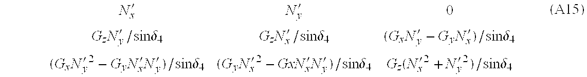
- the x-y-z-to-N′-G transform matrix (A14) becomes: N x ′ N y ′ 0 G z ⁇ N y ′ / sin ⁇ ⁇ ⁇ 4 G z ⁇ N x ′ / sin ⁇ ⁇ ⁇ 4 ( G x ⁇ N y ′ - G y ⁇ N x ′ ) / sin ⁇ ⁇ ⁇ 4 ( G x ⁇ N y ′ 2 - G y ⁇ N x ′ ⁇ N y ′ ) / sin ⁇ ⁇ ⁇ 4 ( G y ⁇ N x ′ 2 - GxN x ′ ⁇ N y ′ ) / sin ⁇ ⁇ ⁇ 4 G z ⁇ ( N x ′ 2 + N y ′ 2
- F g a N ′ ⁇ - ⁇ G x ⁇ - ⁇ y ⁇ - ⁇ z To To F a N ⁇ - ⁇ E ⁇ - ⁇ D N ′ ⁇ - ⁇ G ( A16 )
- the position vector R g e is known in the local N-E-D system from the corrected GPS locations of the Airborne Platform and the Ground Station:
- R g e A function of(GPS a ⁇ GPS b) (A17)
- R g e (Latitude A ⁇ Latitude G) N+(Longitude G ⁇ Longitude A) E+(Altitude G ⁇ Altitude A) D (A18)
- the unit vector G in FIG. 18 is used to generate the unit direction vector F g a from the Airborne Platform (but in the local N-E-D system) to the detected fire, as developed above.
- the triangle shown in FIG. 18 having A (Airborne Platform), F (Fire), and G (Ground Station) at each of its apexes can be solved for the unknown side, R g a , using the law of sines.
- the included angle at G is determined from the triple vector product of F g a , R g e and ⁇ D.
- the scalar product of this with R g e then gives the cosine of the apex angle at G times a constant:
- the included angle at A is determined from the dot product of F g a and R g e to give the cosine of the apex angle at A times a constant:
- R f g Abs(R f g )F g a ⁇ R g e ( ⁇ D)/Abs(F g a ⁇ R g e ⁇ ( ⁇ D)) (A21)
- R f g provides the “Virtual GPS” location of the fire hot spot relative to the known GPS location of the Ground Station. This information is computed continuously on the Airborne Platform and telemetered to the Ground Station.
Abstract
Description


Claims (28)
Priority Applications (1)
| Application Number | Priority Date | Filing Date | Title |
|---|---|---|---|
| US09/267,513 US6281970B1 (en) | 1998-03-12 | 1999-03-12 | Airborne IR fire surveillance system providing firespot geopositioning |
Applications Claiming Priority (2)
| Application Number | Priority Date | Filing Date | Title |
|---|---|---|---|
| US7782198P | 1998-03-12 | 1998-03-12 | |
| US09/267,513 US6281970B1 (en) | 1998-03-12 | 1999-03-12 | Airborne IR fire surveillance system providing firespot geopositioning |
Publications (1)
| Publication Number | Publication Date |
|---|---|
| US6281970B1 true US6281970B1 (en) | 2001-08-28 |
Family
ID=26759715
Family Applications (1)
| Application Number | Title | Priority Date | Filing Date |
|---|---|---|---|
| US09/267,513 Expired - Lifetime US6281970B1 (en) | 1998-03-12 | 1999-03-12 | Airborne IR fire surveillance system providing firespot geopositioning |
Country Status (1)
| Country | Link |
|---|---|
| US (1) | US6281970B1 (en) |
Cited By (78)
| Publication number | Priority date | Publication date | Assignee | Title |
|---|---|---|---|---|
| US6489922B1 (en) * | 2000-04-22 | 2002-12-03 | American Gnc Corporation | Passive/ranging/tracking processing method for collision avoidance guidance and control |
| US6516272B2 (en) * | 2000-12-23 | 2003-02-04 | American Gnc Corporation | Positioning and data integrating method and system thereof |
| US6615165B2 (en) * | 2001-09-27 | 2003-09-02 | Ernest A. Carroll | Cable connections between an unmanned aircraft and a detachable data handling module |
| US20030215143A1 (en) * | 2002-05-20 | 2003-11-20 | Zakrzewski Radoslaw Romuald | Viewing a compartment |
| US20030214583A1 (en) * | 2002-05-20 | 2003-11-20 | Mokhtar Sadok | Distinguishing between fire and non-fire conditions using cameras |
| US20040008253A1 (en) * | 2002-07-10 | 2004-01-15 | Monroe David A. | Comprehensive multi-media surveillance and response system for aircraft, operations centers, airports and other commercial transports, centers and terminals |
| US6694094B2 (en) * | 2000-08-31 | 2004-02-17 | Recon/Optical, Inc. | Dual band framing reconnaissance camera |
| US20040061777A1 (en) * | 2002-05-20 | 2004-04-01 | Mokhtar Sadok | Detecting fire using cameras |
| WO2004027446A1 (en) * | 2002-09-20 | 2004-04-01 | Politecnico Di Torino | Location system |
| US20040097227A1 (en) * | 2002-11-14 | 2004-05-20 | Siegel Neil G. | Communication system with mobile coverage area |
| US20040167709A1 (en) * | 2002-09-20 | 2004-08-26 | M7 Visual Intelligence, Lp | Vehicle based data collection and processing system |
| WO2004083795A2 (en) * | 2002-12-13 | 2004-09-30 | Arete Associates | Optical system |
| US20040189976A1 (en) * | 2002-10-31 | 2004-09-30 | Burns Joseph D. | Method, apparatus and system for sensing air borne hazardous materials |
| EP1508020A1 (en) | 2002-05-30 | 2005-02-23 | Rafael - Armament Development Authority Ltd. | Airborne reconnaissance system |
| US20050103506A1 (en) * | 2003-11-18 | 2005-05-19 | Warrack Malcolm J. | Fire protection method |
| US20050126794A1 (en) * | 2003-12-12 | 2005-06-16 | Palmer Gerald R. | Fire prevention system |
| US20050189122A1 (en) * | 2004-02-06 | 2005-09-01 | Eads Deutschland Gmbh | Method for detecting and combating forest and surface fires |
| US20050273255A1 (en) * | 2004-05-24 | 2005-12-08 | General Motors Corporation | Method and system for programmable mobile vehicle hotspots |
| US20050285953A1 (en) * | 2004-06-25 | 2005-12-29 | Sony Corporation | Monitoring apparatus |
| US20060006337A1 (en) * | 2003-12-12 | 2006-01-12 | Kane David M | Optical system |
| US20060025900A1 (en) * | 2003-06-26 | 2006-02-02 | Michael Arnouse | Apparatus, system and method for aircraft security and anti-hijacking intervention |
| WO2006058618A1 (en) * | 2004-11-30 | 2006-06-08 | Deutsches Zentrum für Luft- und Raumfahrt e.V. | Method for recognising hot targets on the earth |
| US7110035B1 (en) * | 1999-05-25 | 2006-09-19 | Flir Systems Ab | Device and a method for an infrared image analyzing autofocus |
| US20060266942A1 (en) * | 2005-05-26 | 2006-11-30 | Sony Corporation | Imaging device and method, computer program product on computer-readable medium, and imaging system |
| US20060289762A1 (en) * | 2004-04-07 | 2006-12-28 | Hackney Ronald F | Thermal direction unit |
| US20070027591A1 (en) * | 2005-07-27 | 2007-02-01 | Rafael-Armament Development Authority Ltd. | Real-time geographic information system and method |
| US20070046448A1 (en) * | 2002-09-20 | 2007-03-01 | M7 Visual Intelligence | Vehicle based data collection and processing system and imaging sensor system and methods thereof |
| US20070063916A1 (en) * | 2005-09-21 | 2007-03-22 | Malone Bernard L Iii | Versatile antenna for wireless communications |
| US20070129853A1 (en) * | 2004-01-23 | 2007-06-07 | Rafael-Armament Development Authority Ltd. | Airborne reconnaissance system |
| US20070139190A1 (en) * | 2005-12-15 | 2007-06-21 | Kimberly-Clark Worldwide, Inc. | System and method that provide emergency instructions |
| WO2007107988A2 (en) * | 2006-03-23 | 2007-09-27 | Opgal Optronic Industries Ltd. | System for detecting and locating a thermal event and for reactive measures |
| US20070285438A1 (en) * | 2005-06-28 | 2007-12-13 | Lockheed Martin Corporation | Frame grabber |
| US20080046139A1 (en) * | 2005-06-22 | 2008-02-21 | Basilico Albert R | Navigational Aid for Diver |
| US7383129B1 (en) * | 2006-09-07 | 2008-06-03 | Itt Manufacturing Enterprises, Inc. | Method and system for geo-referencing and visualization of detected contaminants |
| US20080191937A1 (en) * | 2007-02-13 | 2008-08-14 | Wherenet Corp. | System and method for tracking vehicles and containers |
| US20080205818A1 (en) * | 2005-01-13 | 2008-08-28 | Kane David M | Image null-balance system with multisector-cell direction sensing |
| US20080266131A1 (en) * | 2007-02-13 | 2008-10-30 | Wherenet Corp. | System, apparatus and method for locating and/or tracking assets |
| US20080291280A1 (en) * | 2002-08-28 | 2008-11-27 | Peters Iii Leo J | Retinal array compound camera system having at least three imaging sensors |
| US20090008554A1 (en) * | 2004-10-22 | 2009-01-08 | Northrop Grumman Corporation | Method for infrared imaging of living or non-living objects including terrains that are either natural or manmade |
| WO2007135671A3 (en) * | 2006-05-22 | 2009-04-09 | Rafael Armament Dev Authority | Methods and system for communication and displaying points-of-interest |
| US20090141591A1 (en) * | 2005-07-15 | 2009-06-04 | Basilico Albert R | System and Method for Extending GPS to Divers and Underwater Vehicles |
| US7640106B1 (en) * | 2005-03-24 | 2009-12-29 | Elbit Systems Ltd. | Hybrid tracker |
| US20100036549A1 (en) * | 2008-07-18 | 2010-02-11 | Honeywell International Inc. | Methods and systems for displaying a predicted distribution of fire retardant material from an aircraft |
| US20100235095A1 (en) * | 2002-09-20 | 2010-09-16 | M7 Visual Intelligence, L.P. | Self-calibrated, remote imaging and data processing system |
| US20100235097A1 (en) * | 2004-06-02 | 2010-09-16 | Athena Technologies, Inc. | Image augmented inertial navigation system (iains) and method |
| US20110122245A1 (en) * | 2009-11-23 | 2011-05-26 | Ashok Kumar Sinha | FOREST FIRE CONTROL SYSTEMS (FFiCS) WITH SCANNER AND OPTICAL /INFRARED RADIATION DETECTOR (SOIRD) AND OPTIONALLY ALSO INCLUDING A SCANNER WITH ACCURATE LOCATION CALCULATOR (SALC) AND A SUPER-EFFICIENT SATELLITE/WIRELESS ANTENNA SYSTEM (SSWAS) |
| US7968845B1 (en) * | 2008-08-04 | 2011-06-28 | Redshift Systems Corporation | System for producing enhanced thermal images |
| US20110157359A1 (en) * | 2009-12-29 | 2011-06-30 | Trimble Navigation Limited | Virtual perspective center aligned with measurement center |
| US20110169946A1 (en) * | 2009-12-07 | 2011-07-14 | Rudin Leonid I | System and method for determining geo-location(s) in images |
| WO2011114059A1 (en) | 2010-03-18 | 2011-09-22 | Flyway-Media | System and method intended for capturing a video sequence pertaining to a target subject in motion on the basis in particular of an autonomous or semi-autonomous aircraft |
| US8229768B1 (en) * | 2007-06-13 | 2012-07-24 | United Services Automobile Association | Systems and methods for processing overhead imagery |
| US8229769B1 (en) | 2007-06-13 | 2012-07-24 | United Services Automobile Association | Systems and methods for processing overhead imagery |
| CN102693601A (en) * | 2012-06-06 | 2012-09-26 | 长春理工大学 | Onboard mobile forest fire monitoring system |
| EP2610831A1 (en) * | 2011-12-30 | 2013-07-03 | Guangzhou SAT Infrared Technology Co., Ltd. | In-flight system with infrared camera and communication method thereof |
| US8660714B2 (en) | 2011-02-22 | 2014-02-25 | Honeywell International Inc. | Aircraft systems and methods for providing exhaust warnings |
| US8994822B2 (en) | 2002-08-28 | 2015-03-31 | Visual Intelligence Lp | Infrastructure mapping system and method |
| US20160054736A1 (en) * | 2014-08-04 | 2016-02-25 | Cummins, Inc. | Apparatus and method for grouping vehicles for cooperative driving |
| CN104567823B (en) * | 2015-01-21 | 2016-09-28 | 中国科学院上海技术物理研究所 | Airborne battle array imager mutative damp dither image motion compensation device |
| US20160299506A1 (en) * | 2013-12-04 | 2016-10-13 | Spatial Information Systems Research Limited | Method and apparatus for developing a flight path |
| EP3165457A3 (en) * | 2015-11-05 | 2017-08-02 | Lockheed Martin Corporation | Methods and systems of applying fire retardant based on onboard sensing and decision making processes |
| CN107945446A (en) * | 2017-11-20 | 2018-04-20 | 北京中科锐景科技有限公司 | The method and apparatus that forest hot spot is identified in monitoring based on multi-source satellite |
| US10223914B2 (en) * | 2016-04-18 | 2019-03-05 | Mando Corporation | System for supporting emergency vehicle using drone |
| US10251331B2 (en) | 2016-05-16 | 2019-04-09 | International Business Machines Corporation | Automated deployment of autonomous devices performing localized environment altering actions |
| US20190228641A1 (en) * | 2016-07-12 | 2019-07-25 | Minimax Gmbh & Co. Kg | System and Method for the Verified Determining of a Fire Status, as well as Vehicle and Central Unit for this Purpose |
| US20190323857A1 (en) * | 2017-04-18 | 2019-10-24 | Ruben Leon | Independently operable low-visibility aid device |
| US10642271B1 (en) * | 2016-08-26 | 2020-05-05 | Amazon Technologies, Inc. | Vehicle guidance camera with zoom lens |
| CN111243217A (en) * | 2020-03-09 | 2020-06-05 | 东风汽车集团有限公司 | Vehicle fire-fighting remote monitoring system |
| WO2020136224A3 (en) * | 2018-12-28 | 2020-09-03 | Safran Electronics & Defense | Aircraft comprising an avionic system with an improved locating device |
| US10896468B1 (en) * | 2007-06-13 | 2021-01-19 | United Services Automobile Association (Usaa) | Systems and methods for using unmanned aerial vehicles |
| US10915152B2 (en) | 2016-04-26 | 2021-02-09 | Src, Inc. | Scalable high-performance embedded computing systems |
| CN112485811A (en) * | 2020-11-03 | 2021-03-12 | 中国直升机设计研究所 | Method for measuring movement of hanging object outside helicopter |
| CN112649884A (en) * | 2021-01-13 | 2021-04-13 | 中国自然资源航空物探遥感中心 | Pod attitude real-time adjusting method applied to aviation electromagnetic measurement system |
| US11009877B2 (en) | 2016-07-12 | 2021-05-18 | Minimax Gmbh & Co. Kg | Unmanned vehicle, system, and method for initiating a fire extinguishing action |
| US11182611B2 (en) | 2019-10-11 | 2021-11-23 | International Business Machines Corporation | Fire detection via remote sensing and mobile sensors |
| USRE49105E1 (en) | 2002-09-20 | 2022-06-14 | Vi Technologies, Llc | Self-calibrated, remote imaging and data processing system |
| US11539971B2 (en) * | 2009-05-29 | 2022-12-27 | Jack Wade | Method for parallel image processing and routing |
| US20230152821A1 (en) * | 2021-11-16 | 2023-05-18 | Industrial Technology Research Institute | Method and system for vehicle head direction compensation |
| US20230342962A1 (en) * | 2020-11-27 | 2023-10-26 | Tsinghua University | Special dangerous terrain recognition method and apparatus for forest fire |
Citations (26)
| Publication number | Priority date | Publication date | Assignee | Title |
|---|---|---|---|---|
| US1990494A (en) | 1934-08-21 | 1935-02-12 | William H Murphy | System of making observations and directing gun fire |
| US4914734A (en) * | 1989-07-21 | 1990-04-03 | The United States Of America As Represented By The Secretary Of The Air Force | Intensity area correlation addition to terrain radiometric area correlation |
| US4949089A (en) | 1989-08-24 | 1990-08-14 | General Dynamics Corporation | Portable target locator system |
| US5155774A (en) | 1989-12-26 | 1992-10-13 | Kabushiki Kaisha Toshiba | Apparatus and method for verifying transformation coefficients to identify image location |
| US5166789A (en) * | 1989-08-25 | 1992-11-24 | Space Island Products & Services, Inc. | Geographical surveying using cameras in combination with flight computers to obtain images with overlaid geographical coordinates |
| US5379045A (en) | 1993-09-01 | 1995-01-03 | Trimble Navigation Limited | SATPS mapping with angle orientation calibrator |
| US5432520A (en) | 1993-10-18 | 1995-07-11 | Hughes Aircraft Company | SAR/GPS inertial method of range measurement |
| US5512903A (en) | 1994-05-23 | 1996-04-30 | Honeywell Inc. | Integrity limit apparatus and method |
| US5554994A (en) | 1995-06-05 | 1996-09-10 | Hughes Missile Systems Company | Self-surveying relative GPS (global positioning system) weapon guidance system |
| US5557397A (en) | 1994-09-21 | 1996-09-17 | Airborne Remote Mapping, Inc. | Aircraft-based topographical data collection and processing system |
| US5570095A (en) | 1994-04-01 | 1996-10-29 | Massachusetts Institute Of Technology | Automatic dependent surveillance air navigation system |
| US5596494A (en) | 1994-11-14 | 1997-01-21 | Kuo; Shihjong | Method and apparatus for acquiring digital maps |
| US5617317A (en) | 1995-01-24 | 1997-04-01 | Honeywell Inc. | True north heading estimator utilizing GPS output information and inertial sensor system output information |
| US5644318A (en) | 1996-02-02 | 1997-07-01 | Trimble Navigation Limited | SATPS dynamic surveying from a moving platform |
| US5672872A (en) * | 1996-03-19 | 1997-09-30 | Hughes Electronics | FLIR boresight alignment |
| US5848377A (en) | 1993-08-29 | 1998-12-08 | Wong; Po Kee | Wong's angles to determine trajectories of objects |
| US5878356A (en) | 1995-06-14 | 1999-03-02 | Agrometrics, Inc. | Aircraft based infrared mapping system for earth based resources |
| US5894323A (en) * | 1996-03-22 | 1999-04-13 | Tasc, Inc, | Airborne imaging system using global positioning system (GPS) and inertial measurement unit (IMU) data |
| US5977908A (en) | 1997-04-15 | 1999-11-02 | Trimble Navigation Limited | Handheld surveying device and method |
| US5999211A (en) * | 1995-05-24 | 1999-12-07 | Imageamerica, Inc. | Direct digital airborne panoramic camera system and method |
| US6084510A (en) | 1997-04-18 | 2000-07-04 | Lemelson; Jerome H. | Danger warning and emergency response system and method |
| US6091359A (en) | 1997-07-14 | 2000-07-18 | Motorola, Inc. | Portable dead reckoning system for extending GPS coverage |
| US6157891A (en) | 1998-11-16 | 2000-12-05 | Lin; Ching-Fang | Positioning and ground proximity warning method and system thereof for vehicle |
| US6166686A (en) | 1998-10-30 | 2000-12-26 | Northrop Grumman Corporation | Corrected magnetic compass |
| US6178363B1 (en) | 1998-12-22 | 2001-01-23 | The Boeing Company | Inertially augmented GPS landing system |
| US6179246B1 (en) * | 1997-12-19 | 2001-01-30 | Bodenseewerk Geratetechnik Gmbh | Seeker head for target tracking missiles |
-
1999
- 1999-03-12 US US09/267,513 patent/US6281970B1/en not_active Expired - Lifetime
Patent Citations (26)
| Publication number | Priority date | Publication date | Assignee | Title |
|---|---|---|---|---|
| US1990494A (en) | 1934-08-21 | 1935-02-12 | William H Murphy | System of making observations and directing gun fire |
| US4914734A (en) * | 1989-07-21 | 1990-04-03 | The United States Of America As Represented By The Secretary Of The Air Force | Intensity area correlation addition to terrain radiometric area correlation |
| US4949089A (en) | 1989-08-24 | 1990-08-14 | General Dynamics Corporation | Portable target locator system |
| US5166789A (en) * | 1989-08-25 | 1992-11-24 | Space Island Products & Services, Inc. | Geographical surveying using cameras in combination with flight computers to obtain images with overlaid geographical coordinates |
| US5155774A (en) | 1989-12-26 | 1992-10-13 | Kabushiki Kaisha Toshiba | Apparatus and method for verifying transformation coefficients to identify image location |
| US5848377A (en) | 1993-08-29 | 1998-12-08 | Wong; Po Kee | Wong's angles to determine trajectories of objects |
| US5379045A (en) | 1993-09-01 | 1995-01-03 | Trimble Navigation Limited | SATPS mapping with angle orientation calibrator |
| US5432520A (en) | 1993-10-18 | 1995-07-11 | Hughes Aircraft Company | SAR/GPS inertial method of range measurement |
| US5570095A (en) | 1994-04-01 | 1996-10-29 | Massachusetts Institute Of Technology | Automatic dependent surveillance air navigation system |
| US5512903A (en) | 1994-05-23 | 1996-04-30 | Honeywell Inc. | Integrity limit apparatus and method |
| US5557397A (en) | 1994-09-21 | 1996-09-17 | Airborne Remote Mapping, Inc. | Aircraft-based topographical data collection and processing system |
| US5596494A (en) | 1994-11-14 | 1997-01-21 | Kuo; Shihjong | Method and apparatus for acquiring digital maps |
| US5617317A (en) | 1995-01-24 | 1997-04-01 | Honeywell Inc. | True north heading estimator utilizing GPS output information and inertial sensor system output information |
| US5999211A (en) * | 1995-05-24 | 1999-12-07 | Imageamerica, Inc. | Direct digital airborne panoramic camera system and method |
| US5554994A (en) | 1995-06-05 | 1996-09-10 | Hughes Missile Systems Company | Self-surveying relative GPS (global positioning system) weapon guidance system |
| US5878356A (en) | 1995-06-14 | 1999-03-02 | Agrometrics, Inc. | Aircraft based infrared mapping system for earth based resources |
| US5644318A (en) | 1996-02-02 | 1997-07-01 | Trimble Navigation Limited | SATPS dynamic surveying from a moving platform |
| US5672872A (en) * | 1996-03-19 | 1997-09-30 | Hughes Electronics | FLIR boresight alignment |
| US5894323A (en) * | 1996-03-22 | 1999-04-13 | Tasc, Inc, | Airborne imaging system using global positioning system (GPS) and inertial measurement unit (IMU) data |
| US5977908A (en) | 1997-04-15 | 1999-11-02 | Trimble Navigation Limited | Handheld surveying device and method |
| US6084510A (en) | 1997-04-18 | 2000-07-04 | Lemelson; Jerome H. | Danger warning and emergency response system and method |
| US6091359A (en) | 1997-07-14 | 2000-07-18 | Motorola, Inc. | Portable dead reckoning system for extending GPS coverage |
| US6179246B1 (en) * | 1997-12-19 | 2001-01-30 | Bodenseewerk Geratetechnik Gmbh | Seeker head for target tracking missiles |
| US6166686A (en) | 1998-10-30 | 2000-12-26 | Northrop Grumman Corporation | Corrected magnetic compass |
| US6157891A (en) | 1998-11-16 | 2000-12-05 | Lin; Ching-Fang | Positioning and ground proximity warning method and system thereof for vehicle |
| US6178363B1 (en) | 1998-12-22 | 2001-01-23 | The Boeing Company | Inertially augmented GPS landing system |
Cited By (154)
| Publication number | Priority date | Publication date | Assignee | Title |
|---|---|---|---|---|
| US7110035B1 (en) * | 1999-05-25 | 2006-09-19 | Flir Systems Ab | Device and a method for an infrared image analyzing autofocus |
| US20030146869A1 (en) * | 2000-04-22 | 2003-08-07 | Ching-Fang Lin | Passive/ranging/tracking processing method for collision avoidance guidance |
| US6639553B2 (en) * | 2000-04-22 | 2003-10-28 | Ching-Fang Lin | Passive/ranging/tracking processing method for collision avoidance guidance |
| US6489922B1 (en) * | 2000-04-22 | 2002-12-03 | American Gnc Corporation | Passive/ranging/tracking processing method for collision avoidance guidance and control |
| US6694094B2 (en) * | 2000-08-31 | 2004-02-17 | Recon/Optical, Inc. | Dual band framing reconnaissance camera |
| US6826358B2 (en) | 2000-08-31 | 2004-11-30 | Recon/Optical, Inc. | Dual band hyperspectral framing reconnaissance camera |
| US6516272B2 (en) * | 2000-12-23 | 2003-02-04 | American Gnc Corporation | Positioning and data integrating method and system thereof |
| US6615165B2 (en) * | 2001-09-27 | 2003-09-02 | Ernest A. Carroll | Cable connections between an unmanned aircraft and a detachable data handling module |
| US20030214583A1 (en) * | 2002-05-20 | 2003-11-20 | Mokhtar Sadok | Distinguishing between fire and non-fire conditions using cameras |
| US20040061777A1 (en) * | 2002-05-20 | 2004-04-01 | Mokhtar Sadok | Detecting fire using cameras |
| US7302101B2 (en) | 2002-05-20 | 2007-11-27 | Simmonds Precision Products, Inc. | Viewing a compartment |
| US7280696B2 (en) | 2002-05-20 | 2007-10-09 | Simmonds Precision Products, Inc. | Video detection/verification system |
| US7256818B2 (en) | 2002-05-20 | 2007-08-14 | Simmonds Precision Products, Inc. | Detecting fire using cameras |
| US7245315B2 (en) | 2002-05-20 | 2007-07-17 | Simmonds Precision Products, Inc. | Distinguishing between fire and non-fire conditions using cameras |
| US20030215143A1 (en) * | 2002-05-20 | 2003-11-20 | Zakrzewski Radoslaw Romuald | Viewing a compartment |
| US20050177307A1 (en) * | 2002-05-30 | 2005-08-11 | Rafael-Armament Development Authority Ltd | Airborne reconnaissance system |
| US7136726B2 (en) * | 2002-05-30 | 2006-11-14 | Rafael Armament Development Authority Ltd. | Airborne reconnaissance system |
| EP1508020B2 (en) † | 2002-05-30 | 2017-03-08 | Rafael - Armament Development Authority Ltd. | Airborne reconnaissance system |
| EP1508020A1 (en) | 2002-05-30 | 2005-02-23 | Rafael - Armament Development Authority Ltd. | Airborne reconnaissance system |
| US20070130599A1 (en) * | 2002-07-10 | 2007-06-07 | Monroe David A | Comprehensive multi-media surveillance and response system for aircraft, operations centers, airports and other commercial transports, centers and terminals |
| US20040008253A1 (en) * | 2002-07-10 | 2004-01-15 | Monroe David A. | Comprehensive multi-media surveillance and response system for aircraft, operations centers, airports and other commercial transports, centers and terminals |
| US8589994B2 (en) | 2002-07-10 | 2013-11-19 | David A. Monroe | Comprehensive multi-media surveillance and response system for aircraft, operations centers, airports and other commercial transports, centers and terminals |
| US7131136B2 (en) | 2002-07-10 | 2006-10-31 | E-Watch, Inc. | Comprehensive multi-media surveillance and response system for aircraft, operations centers, airports and other commercial transports, centers and terminals |
| US20090322883A1 (en) * | 2002-08-28 | 2009-12-31 | Visual Intelligence Systems, Inc. | Method of producing a remote imaging array |
| US8994822B2 (en) | 2002-08-28 | 2015-03-31 | Visual Intelligence Lp | Infrastructure mapping system and method |
| US20090295924A1 (en) * | 2002-08-28 | 2009-12-03 | M7 Visual Intelligence, L.P. | Retinal concave array compound camera system |
| US8334903B2 (en) | 2002-08-28 | 2012-12-18 | Visual Intelligence, L.P. | Retinal array compound camera system having at least three imaging sensors |
| US20080291280A1 (en) * | 2002-08-28 | 2008-11-27 | Peters Iii Leo J | Retinal array compound camera system having at least three imaging sensors |
| US8471907B2 (en) | 2002-08-28 | 2013-06-25 | Visual Intelligence, LP | Method of producing a remote imaging array |
| US8896695B2 (en) | 2002-08-28 | 2014-11-25 | Visual Intelligence Lp | Retinal concave array compound camera system |
| US20100235095A1 (en) * | 2002-09-20 | 2010-09-16 | M7 Visual Intelligence, L.P. | Self-calibrated, remote imaging and data processing system |
| US20040167709A1 (en) * | 2002-09-20 | 2004-08-26 | M7 Visual Intelligence, Lp | Vehicle based data collection and processing system |
| WO2004027446A1 (en) * | 2002-09-20 | 2004-04-01 | Politecnico Di Torino | Location system |
| US8483960B2 (en) | 2002-09-20 | 2013-07-09 | Visual Intelligence, LP | Self-calibrated, remote imaging and data processing system |
| US9389298B2 (en) | 2002-09-20 | 2016-07-12 | Visual Intelligence Lp | Self-calibrated, remote imaging and data processing system |
| US7127348B2 (en) * | 2002-09-20 | 2006-10-24 | M7 Visual Intelligence, Lp | Vehicle based data collection and processing system |
| USRE49105E1 (en) | 2002-09-20 | 2022-06-14 | Vi Technologies, Llc | Self-calibrated, remote imaging and data processing system |
| US20070046448A1 (en) * | 2002-09-20 | 2007-03-01 | M7 Visual Intelligence | Vehicle based data collection and processing system and imaging sensor system and methods thereof |
| US9797980B2 (en) | 2002-09-20 | 2017-10-24 | Visual Intelligence Lp | Self-calibrated, remote imaging and data processing system |
| US7725258B2 (en) | 2002-09-20 | 2010-05-25 | M7 Visual Intelligence, L.P. | Vehicle based data collection and processing system and imaging sensor system and methods thereof |
| US20040189976A1 (en) * | 2002-10-31 | 2004-09-30 | Burns Joseph D. | Method, apparatus and system for sensing air borne hazardous materials |
| US6941806B2 (en) | 2002-10-31 | 2005-09-13 | Airdat, Llc | Method, apparatus and system for sensing air borne hazardous materials |
| US6904280B2 (en) * | 2002-11-14 | 2005-06-07 | Northrop Grumman Corporation | Communication system with mobile coverage area |
| US20040097227A1 (en) * | 2002-11-14 | 2004-05-20 | Siegel Neil G. | Communication system with mobile coverage area |
| WO2004083795A3 (en) * | 2002-12-13 | 2005-03-31 | Arete Associates | Optical system |
| WO2004083795A2 (en) * | 2002-12-13 | 2004-09-30 | Arete Associates | Optical system |
| US7379795B2 (en) * | 2003-06-26 | 2008-05-27 | Michael Arnouse | Apparatus, system and method for aircraft security and anti-hijacking intervention |
| US20060025900A1 (en) * | 2003-06-26 | 2006-02-02 | Michael Arnouse | Apparatus, system and method for aircraft security and anti-hijacking intervention |
| US20050103506A1 (en) * | 2003-11-18 | 2005-05-19 | Warrack Malcolm J. | Fire protection method |
| US7297934B2 (en) | 2003-12-12 | 2007-11-20 | ARETé ASSOCIATES | Optical system |
| US20050126794A1 (en) * | 2003-12-12 | 2005-06-16 | Palmer Gerald R. | Fire prevention system |
| US20060006337A1 (en) * | 2003-12-12 | 2006-01-12 | Kane David M | Optical system |
| US20080211912A1 (en) * | 2004-01-23 | 2008-09-04 | Rafael-Armament Development Authority Ltd. | Airborne reconnaissance system |
| US8527115B2 (en) | 2004-01-23 | 2013-09-03 | Rafael Armament Development Authority Ltd. | Airborne reconnaissance system |
| US20070129853A1 (en) * | 2004-01-23 | 2007-06-07 | Rafael-Armament Development Authority Ltd. | Airborne reconnaissance system |
| US7308342B2 (en) | 2004-01-23 | 2007-12-11 | Rafael Armament Development Authority Ltd. | Airborne reconnaissance system |
| US20050189122A1 (en) * | 2004-02-06 | 2005-09-01 | Eads Deutschland Gmbh | Method for detecting and combating forest and surface fires |
| US7337156B2 (en) | 2004-02-06 | 2008-02-26 | Eads Deutschland Gmbh | Method for detecting and combating forest and surface fires |
| EP1561493A3 (en) * | 2004-02-06 | 2006-11-22 | EADS Deutschland GmbH | Method for detecting, planing and fighting of forest fires or surface fires |
| US20060289762A1 (en) * | 2004-04-07 | 2006-12-28 | Hackney Ronald F | Thermal direction unit |
| US7548815B2 (en) * | 2004-05-24 | 2009-06-16 | General Motors Corporation | Method and system for programmable mobile vehicle hotspots |
| US20050273255A1 (en) * | 2004-05-24 | 2005-12-08 | General Motors Corporation | Method and system for programmable mobile vehicle hotspots |
| US20100235097A1 (en) * | 2004-06-02 | 2010-09-16 | Athena Technologies, Inc. | Image augmented inertial navigation system (iains) and method |
| US8407000B2 (en) * | 2004-06-02 | 2013-03-26 | Rockwell Collins Control Technologies, Inc. | Image augmented inertial navigation system (IAINS) and method |
| US7423272B2 (en) * | 2004-06-25 | 2008-09-09 | Sony Corporation | Monitoring apparatus |
| US20050285953A1 (en) * | 2004-06-25 | 2005-12-29 | Sony Corporation | Monitoring apparatus |
| US7732771B2 (en) | 2004-06-25 | 2010-06-08 | Sony Corporation | Monitoring apparatus |
| US20090008554A1 (en) * | 2004-10-22 | 2009-01-08 | Northrop Grumman Corporation | Method for infrared imaging of living or non-living objects including terrains that are either natural or manmade |
| US7480572B2 (en) * | 2004-11-30 | 2009-01-20 | Deutsches Zentrum für Luft- und Raumfahrt a. V. | Method for recognising hot targets on the Earth |
| WO2006058618A1 (en) * | 2004-11-30 | 2006-06-08 | Deutsches Zentrum für Luft- und Raumfahrt e.V. | Method for recognising hot targets on the earth |
| US20080027649A1 (en) * | 2004-11-30 | 2008-01-31 | Deutsches Zentrum Fur Luft-Und Raumfahrt E.V. | Method for Recognising Hot Targets on the Earth |
| US20080205818A1 (en) * | 2005-01-13 | 2008-08-28 | Kane David M | Image null-balance system with multisector-cell direction sensing |
| US7733469B2 (en) | 2005-01-13 | 2010-06-08 | Arete' Associates | Image null-balance system with multisector-cell direction sensing |
| US7640106B1 (en) * | 2005-03-24 | 2009-12-29 | Elbit Systems Ltd. | Hybrid tracker |
| US7459685B2 (en) * | 2005-05-26 | 2008-12-02 | Sony Corporation | Imaging device and method, computer program product on computer-readable medium, and imaging system |
| US20060266942A1 (en) * | 2005-05-26 | 2006-11-30 | Sony Corporation | Imaging device and method, computer program product on computer-readable medium, and imaging system |
| US7650208B2 (en) * | 2005-06-22 | 2010-01-19 | Estate Of Albert R. Basilico | Navigational aid for diver |
| US20080046139A1 (en) * | 2005-06-22 | 2008-02-21 | Basilico Albert R | Navigational Aid for Diver |
| US7668403B2 (en) | 2005-06-28 | 2010-02-23 | Lockheed Martin Corporation | Frame grabber |
| US20070285438A1 (en) * | 2005-06-28 | 2007-12-13 | Lockheed Martin Corporation | Frame grabber |
| US20090141591A1 (en) * | 2005-07-15 | 2009-06-04 | Basilico Albert R | System and Method for Extending GPS to Divers and Underwater Vehicles |
| US7969822B2 (en) * | 2005-07-15 | 2011-06-28 | Estate Of Albert R. Basilico | System and method for extending GPS to divers and underwater vehicles |
| US8036678B2 (en) | 2005-07-27 | 2011-10-11 | Rafael Advanced Defense Systems Ltd. | Real-time geographic information system and method |
| US20070027591A1 (en) * | 2005-07-27 | 2007-02-01 | Rafael-Armament Development Authority Ltd. | Real-time geographic information system and method |
| US20070063916A1 (en) * | 2005-09-21 | 2007-03-22 | Malone Bernard L Iii | Versatile antenna for wireless communications |
| US20070139190A1 (en) * | 2005-12-15 | 2007-06-21 | Kimberly-Clark Worldwide, Inc. | System and method that provide emergency instructions |
| US7880610B2 (en) | 2005-12-15 | 2011-02-01 | Binforma Group Limited Liability Company | System and method that provide emergency instructions |
| WO2007107988A2 (en) * | 2006-03-23 | 2007-09-27 | Opgal Optronic Industries Ltd. | System for detecting and locating a thermal event and for reactive measures |
| WO2007107988A3 (en) * | 2006-03-23 | 2009-04-16 | Opgal Optronic Ind Ltd | System for detecting and locating a thermal event and for reactive measures |
| WO2007135671A3 (en) * | 2006-05-22 | 2009-04-09 | Rafael Armament Dev Authority | Methods and system for communication and displaying points-of-interest |
| US8116526B2 (en) | 2006-05-22 | 2012-02-14 | Rafael Advanced Defense Systems Ltd. | Methods and system for communication and displaying points-of-interest |
| US8115768B2 (en) | 2006-05-22 | 2012-02-14 | Rafael Advanced Defense Systems Ltd. | Methods and system for communication and displaying points-of-interest |
| US20090097710A1 (en) * | 2006-05-22 | 2009-04-16 | Rafael Advanced Defense Systems Ltd. | Methods and system for communication and displaying points-of-interest |
| US20090289957A1 (en) * | 2006-05-22 | 2009-11-26 | Rafael Advanced Defense Systems Ltd | Methods and system for communication and displaying points-of-interest |
| US7383129B1 (en) * | 2006-09-07 | 2008-06-03 | Itt Manufacturing Enterprises, Inc. | Method and system for geo-referencing and visualization of detected contaminants |
| US20080266131A1 (en) * | 2007-02-13 | 2008-10-30 | Wherenet Corp. | System, apparatus and method for locating and/or tracking assets |
| WO2008100499A3 (en) * | 2007-02-13 | 2009-12-23 | Wherenet Corp | System and method for tracking vehicles and containers |
| US7755541B2 (en) | 2007-02-13 | 2010-07-13 | Wherenet Corp. | System and method for tracking vehicles and containers |
| US9880283B2 (en) | 2007-02-13 | 2018-01-30 | Zih Corp. | System, apparatus and method for locating and/or tracking assets |
| US20080191937A1 (en) * | 2007-02-13 | 2008-08-14 | Wherenet Corp. | System and method for tracking vehicles and containers |
| US11715160B1 (en) | 2007-06-13 | 2023-08-01 | United Services Automobile Association (Usaa) | Systems and methods for using unmanned aerial vehicles |
| US10896468B1 (en) * | 2007-06-13 | 2021-01-19 | United Services Automobile Association (Usaa) | Systems and methods for using unmanned aerial vehicles |
| US8229769B1 (en) | 2007-06-13 | 2012-07-24 | United Services Automobile Association | Systems and methods for processing overhead imagery |
| US8229768B1 (en) * | 2007-06-13 | 2012-07-24 | United Services Automobile Association | Systems and methods for processing overhead imagery |
| US8650106B1 (en) * | 2007-06-13 | 2014-02-11 | United Sevices Automobile Association | Systems and methods for processing overhead imagery |
| US20100036549A1 (en) * | 2008-07-18 | 2010-02-11 | Honeywell International Inc. | Methods and systems for displaying a predicted distribution of fire retardant material from an aircraft |
| US8138475B2 (en) * | 2008-08-04 | 2012-03-20 | Redshift Systems Corporation | System for producing enhanced thermal images |
| US8222602B2 (en) * | 2008-08-04 | 2012-07-17 | Redshift Systems Corporation | System for producing enhanced thermal images |
| US20120145903A1 (en) * | 2008-08-04 | 2012-06-14 | Redshift Systems Corporation | System for producing enhanced thermal images |
| US20110254952A1 (en) * | 2008-08-04 | 2011-10-20 | Redshift Systems Corporation | System for producing enhanced thermal images |
| US7968845B1 (en) * | 2008-08-04 | 2011-06-28 | Redshift Systems Corporation | System for producing enhanced thermal images |
| US11539971B2 (en) * | 2009-05-29 | 2022-12-27 | Jack Wade | Method for parallel image processing and routing |
| US20230262244A1 (en) * | 2009-05-29 | 2023-08-17 | Jack Wade | Method for parallel image processing and routing |
| US20110122245A1 (en) * | 2009-11-23 | 2011-05-26 | Ashok Kumar Sinha | FOREST FIRE CONTROL SYSTEMS (FFiCS) WITH SCANNER AND OPTICAL /INFRARED RADIATION DETECTOR (SOIRD) AND OPTIONALLY ALSO INCLUDING A SCANNER WITH ACCURATE LOCATION CALCULATOR (SALC) AND A SUPER-EFFICIENT SATELLITE/WIRELESS ANTENNA SYSTEM (SSWAS) |
| US9083859B2 (en) * | 2009-12-07 | 2015-07-14 | Cognitech, Inc. | System and method for determining geo-location(s) in images |
| US11704869B2 (en) | 2009-12-07 | 2023-07-18 | Cognitech, Inc. | System and method for determining geo-location(s) in images |
| US20150125044A1 (en) * | 2009-12-07 | 2015-05-07 | Cognitech, Inc. | System and method for determining geo-location(s) in images |
| US20110169946A1 (en) * | 2009-12-07 | 2011-07-14 | Rudin Leonid I | System and method for determining geo-location(s) in images |
| US8934008B2 (en) * | 2009-12-07 | 2015-01-13 | Cognitech, Inc. | System and method for determining geo-location(s) in images |
| US20110157359A1 (en) * | 2009-12-29 | 2011-06-30 | Trimble Navigation Limited | Virtual perspective center aligned with measurement center |
| US9879992B2 (en) * | 2009-12-29 | 2018-01-30 | Trimble Inc. | Virtual perspective center aligned with measurement center |
| FR2957690A1 (en) * | 2010-03-18 | 2011-09-23 | Flyway Media | SYSTEM AND METHOD FOR CAPTURING A VIDEO SEQUENCE ON A MOVING TARGET SUBJECT PARTICULARLY FROM AN AUTONOMOUS OR SEMI AUTONOMOUS AIRCRAFT. |
| WO2011114059A1 (en) | 2010-03-18 | 2011-09-22 | Flyway-Media | System and method intended for capturing a video sequence pertaining to a target subject in motion on the basis in particular of an autonomous or semi-autonomous aircraft |
| US8660714B2 (en) | 2011-02-22 | 2014-02-25 | Honeywell International Inc. | Aircraft systems and methods for providing exhaust warnings |
| EP2610831A1 (en) * | 2011-12-30 | 2013-07-03 | Guangzhou SAT Infrared Technology Co., Ltd. | In-flight system with infrared camera and communication method thereof |
| CN102693601A (en) * | 2012-06-06 | 2012-09-26 | 长春理工大学 | Onboard mobile forest fire monitoring system |
| US9983584B2 (en) * | 2013-12-04 | 2018-05-29 | Spatial Information Systems Research Limited | Method and apparatus for developing a flight path |
| US20160299506A1 (en) * | 2013-12-04 | 2016-10-13 | Spatial Information Systems Research Limited | Method and apparatus for developing a flight path |
| US9551993B2 (en) * | 2014-08-04 | 2017-01-24 | Cummins, Inc. | Apparatus and method for grouping vehicles for cooperative driving |
| US9851722B2 (en) | 2014-08-04 | 2017-12-26 | Cummins Inc. | Apparatus and method for grouping vehicles for cooperative driving |
| US20160054736A1 (en) * | 2014-08-04 | 2016-02-25 | Cummins, Inc. | Apparatus and method for grouping vehicles for cooperative driving |
| CN104567823B (en) * | 2015-01-21 | 2016-09-28 | 中国科学院上海技术物理研究所 | Airborne battle array imager mutative damp dither image motion compensation device |
| EP3165457A3 (en) * | 2015-11-05 | 2017-08-02 | Lockheed Martin Corporation | Methods and systems of applying fire retardant based on onboard sensing and decision making processes |
| US10223914B2 (en) * | 2016-04-18 | 2019-03-05 | Mando Corporation | System for supporting emergency vehicle using drone |
| US10915152B2 (en) | 2016-04-26 | 2021-02-09 | Src, Inc. | Scalable high-performance embedded computing systems |
| US10667455B2 (en) | 2016-05-16 | 2020-06-02 | International Business Machines Corporation | Automated deployment of autonomous devices performing localized environment altering actions |
| US10251331B2 (en) | 2016-05-16 | 2019-04-09 | International Business Machines Corporation | Automated deployment of autonomous devices performing localized environment altering actions |
| US11009877B2 (en) | 2016-07-12 | 2021-05-18 | Minimax Gmbh & Co. Kg | Unmanned vehicle, system, and method for initiating a fire extinguishing action |
| US20190228641A1 (en) * | 2016-07-12 | 2019-07-25 | Minimax Gmbh & Co. Kg | System and Method for the Verified Determining of a Fire Status, as well as Vehicle and Central Unit for this Purpose |
| US10825335B2 (en) * | 2016-07-12 | 2020-11-03 | Minimax Gmbh & Co. Kg | System and method for the verified determining of a fire status, as well as vehicle and central unit for this purpose |
| US10642271B1 (en) * | 2016-08-26 | 2020-05-05 | Amazon Technologies, Inc. | Vehicle guidance camera with zoom lens |
| US20190323857A1 (en) * | 2017-04-18 | 2019-10-24 | Ruben Leon | Independently operable low-visibility aid device |
| US11629975B2 (en) * | 2017-04-18 | 2023-04-18 | Ruben Leon | Independently operable low-visibility aid device |
| US20230243668A1 (en) * | 2017-04-18 | 2023-08-03 | Ruben Leon | Independently operable low-visibility aid device |
| CN107945446A (en) * | 2017-11-20 | 2018-04-20 | 北京中科锐景科技有限公司 | The method and apparatus that forest hot spot is identified in monitoring based on multi-source satellite |
| WO2020136224A3 (en) * | 2018-12-28 | 2020-09-03 | Safran Electronics & Defense | Aircraft comprising an avionic system with an improved locating device |
| US11182611B2 (en) | 2019-10-11 | 2021-11-23 | International Business Machines Corporation | Fire detection via remote sensing and mobile sensors |
| CN111243217A (en) * | 2020-03-09 | 2020-06-05 | 东风汽车集团有限公司 | Vehicle fire-fighting remote monitoring system |
| CN112485811A (en) * | 2020-11-03 | 2021-03-12 | 中国直升机设计研究所 | Method for measuring movement of hanging object outside helicopter |
| CN112485811B (en) * | 2020-11-03 | 2023-09-08 | 中国直升机设计研究所 | Method for measuring movement of outer hanging object of helicopter |
| US20230342962A1 (en) * | 2020-11-27 | 2023-10-26 | Tsinghua University | Special dangerous terrain recognition method and apparatus for forest fire |
| CN112649884A (en) * | 2021-01-13 | 2021-04-13 | 中国自然资源航空物探遥感中心 | Pod attitude real-time adjusting method applied to aviation electromagnetic measurement system |
| CN112649884B (en) * | 2021-01-13 | 2024-02-09 | 中国自然资源航空物探遥感中心 | Nacelle attitude real-time adjustment method applied to aviation electromagnetic measurement system |
| US20230152821A1 (en) * | 2021-11-16 | 2023-05-18 | Industrial Technology Research Institute | Method and system for vehicle head direction compensation |
Similar Documents
| Publication | Publication Date | Title |
|---|---|---|
| US6281970B1 (en) | Airborne IR fire surveillance system providing firespot geopositioning | |
| US6422508B1 (en) | System for robotic control of imaging data having a steerable gimbal mounted spectral sensor and methods | |
| US6840480B2 (en) | Miniature, unmanned aircraft with interchangeable data module | |
| US9533760B1 (en) | Image monitoring and display from unmanned vehicle | |
| US20180196122A1 (en) | Electromagnetic radiation source locating system | |
| USRE45253E1 (en) | Remote image management system (RIMS) | |
| Ambrosia et al. | Demonstrating UAV-acquired real-time thermal data over fires | |
| AU2004301360B2 (en) | Method and apparatus for video on demand | |
| JP2783522B2 (en) | Satellite focal plane array imager | |
| USRE40801E1 (en) | GPS airborne target geolocating method | |
| JP4946398B2 (en) | Surveillance satellite | |
| US11374648B2 (en) | Radio link coverage map generation using link quality and position data of mobile platform | |
| AU2342597A (en) | Airborne imaging system | |
| EP0190258A1 (en) | Surveying satellite incorporating star-sensing attitude determination subsystem | |
| US20060018642A1 (en) | Mobile laser designated infrared multimedia mapping system | |
| JP2695393B2 (en) | Position specifying method and device | |
| Hashimoto et al. | Light weight sensors for the autonomous asteroid landing of MUSES-C mission | |
| JP2007033258A (en) | Method and device for observing object to be observed | |
| JP2007106269A (en) | Unmanned helicopter | |
| US11499827B2 (en) | Multi-aircraft vision and datalink based navigation system and method | |
| Teston et al. | The PROBA-1 microsatellite | |
| US20220189319A1 (en) | Mobile surveillance systems and methods for uas operational support | |
| JPH1185284A (en) | Monitoring device | |
| Teston et al. | Proba, an ESA technology demonstration mission, results after 3 years in orbit | |
| Nichols | Firefly system concept |
Legal Events
| Date | Code | Title | Description |
|---|---|---|---|
| AS | Assignment |
Owner name: WILLIAMS, JOHN H., CALIFORNIA Free format text: ASSIGNMENT OF ASSIGNORS INTEREST;ASSIGNOR:COOPER, GUY F.;REEL/FRAME:011995/0738 Effective date: 20010713 |
|
| AS | Assignment |
Owner name: SYNERGISTIX, LLC, CALIFORNIA Free format text: ASSIGNMENT OF ASSIGNORS INTEREST;ASSIGNOR:WILLIAMS, JOHN;REEL/FRAME:012006/0694 Effective date: 20010718 |
|
| STCF | Information on status: patent grant |
Free format text: PATENTED CASE |
|
| FPAY | Fee payment |
Year of fee payment: 4 |
|
| FPAY | Fee payment |
Year of fee payment: 8 |
|
| FPAY | Fee payment |
Year of fee payment: 12 |