US6188906B1 - Method for coverage optimization of multi-frequency assignment system - Google Patents
Method for coverage optimization of multi-frequency assignment system Download PDFInfo
- Publication number
- US6188906B1 US6188906B1 US09/224,233 US22423398A US6188906B1 US 6188906 B1 US6188906 B1 US 6188906B1 US 22423398 A US22423398 A US 22423398A US 6188906 B1 US6188906 B1 US 6188906B1
- Authority
- US
- United States
- Prior art keywords
- pilot
- base station
- power
- ratio
- dummy
- Prior art date
- Legal status (The legal status is an assumption and is not a legal conclusion. Google has not performed a legal analysis and makes no representation as to the accuracy of the status listed.)
- Expired - Lifetime
Links
- 238000000034 method Methods 0.000 title claims abstract description 33
- 238000005457 optimization Methods 0.000 title abstract description 5
- 238000004891 communication Methods 0.000 claims abstract description 30
- 238000005259 measurement Methods 0.000 description 5
- 238000012360 testing method Methods 0.000 description 4
- 238000001228 spectrum Methods 0.000 description 3
- 238000012986 modification Methods 0.000 description 2
- 230000004048 modification Effects 0.000 description 2
- 238000013459 approach Methods 0.000 description 1
- 230000001413 cellular effect Effects 0.000 description 1
- 230000001427 coherent effect Effects 0.000 description 1
- 230000006866 deterioration Effects 0.000 description 1
- 230000003595 spectral effect Effects 0.000 description 1
Images


Classifications
-
- H—ELECTRICITY
- H04—ELECTRIC COMMUNICATION TECHNIQUE
- H04W—WIRELESS COMMUNICATION NETWORKS
- H04W52/00—Power management, e.g. TPC [Transmission Power Control], power saving or power classes
- H04W52/04—TPC
- H04W52/30—TPC using constraints in the total amount of available transmission power
- H04W52/36—TPC using constraints in the total amount of available transmission power with a discrete range or set of values, e.g. step size, ramping or offsets
-
- H—ELECTRICITY
- H04—ELECTRIC COMMUNICATION TECHNIQUE
- H04W—WIRELESS COMMUNICATION NETWORKS
- H04W16/00—Network planning, e.g. coverage or traffic planning tools; Network deployment, e.g. resource partitioning or cells structures
- H04W16/02—Resource partitioning among network components, e.g. reuse partitioning
- H04W16/06—Hybrid resource partitioning, e.g. channel borrowing
-
- H—ELECTRICITY
- H04—ELECTRIC COMMUNICATION TECHNIQUE
- H04W—WIRELESS COMMUNICATION NETWORKS
- H04W36/00—Hand-off or reselection arrangements
- H04W36/08—Reselecting an access point
-
- H—ELECTRICITY
- H04—ELECTRIC COMMUNICATION TECHNIQUE
- H04W—WIRELESS COMMUNICATION NETWORKS
- H04W48/00—Access restriction; Network selection; Access point selection
- H04W48/08—Access restriction or access information delivery, e.g. discovery data delivery
-
- H—ELECTRICITY
- H04—ELECTRIC COMMUNICATION TECHNIQUE
- H04W—WIRELESS COMMUNICATION NETWORKS
- H04W72/00—Local resource management
- H04W72/04—Wireless resource allocation
- H04W72/044—Wireless resource allocation based on the type of the allocated resource
- H04W72/0453—Resources in frequency domain, e.g. a carrier in FDMA
-
- H—ELECTRICITY
- H04—ELECTRIC COMMUNICATION TECHNIQUE
- H04W—WIRELESS COMMUNICATION NETWORKS
- H04W72/00—Local resource management
- H04W72/50—Allocation or scheduling criteria for wireless resources
- H04W72/54—Allocation or scheduling criteria for wireless resources based on quality criteria
- H04W72/541—Allocation or scheduling criteria for wireless resources based on quality criteria using the level of interference
Definitions
- the present invention relates generally to wireless telecommunications and more particularly to a method for coverage optimization of a multi-frequency assignment (multi-FA) system.
- multi-FA multi-frequency assignment
- CDMA code division multiple access
- a CDMA base station uses only a single CDMA frequency band to support communications to subscriber stations within the cell.
- a multi-frequency assignment (multi-FA) method for accommodating a large number of subscribers is employed.
- multi-FA two or more radio frequency (RF) channels are operated simultaneously, with each RF channel supporting multiple communication signals via CDMA.
- RF radio frequency
- each base station transmits a unique pilot signal on a pilot channel (using the same frequency band as the associated traffic channels).
- the pilot signal is an unmodulated, direct sequence, spread spectrum signal transmitted continuously by each base station using a common pseudorandom noise (PN) spreading code.
- PN pseudorandom noise
- Each base station or base station sector transmits the common pilot sequence offset in time from the other base stations or sectors.
- the subscriber stations can identify a base station based on the code phase offset of the pilot signal that it receives from the base station.
- the pilot signal also provides a phase reference for coherent demodulation and the basis of the signal strength measurements used in handoff determination.
- each frequency band has its own pilot channel. In practice, it is necessary to determine the power allocation for the pilot channel relative to the traffic channels.
- Tx IF transmit intermediate frequency
- AGC Automatic Gain Control
- Tx_Atten a transmit attenuator value, “Tx_Atten”, is confirmed for a first frequency assignment FA# 1 of each sector in current operation. (The value of Tx_Atten controls adjustment of the transmit power level.);
- a value for Tx_Atten of a second frequency assignment, FA# 2 is set equal to that for FA# 1 ;
- the optimized value for Tx_Atten of FA# 2 is output, e.g., to an operator who manages parameters of a base station manager (BSM).
- BSM base station manager
- the conventional optimization method outlined above is limited to the case in which there is a constant number of RF channels in all base stations.
- a handoff problem may occur between adjacent base stations that have a different number of frequency assignments. For example, assume that two base stations A and B are adjacent, FA# 1 and FA# 2 are being used in base station A and only FA# 1 is being used in base station B. A mobile station can not search the pilot of base station B when the mobile station is tuned to FA# 2 of base station A. As a result, when this mobile station is traveling towards base station B, a handoff to base station B can not be performed (absent methodology to handle this situation) and it is highly probable that the call will be dropped due to the link deterioration.
- a base station handling low traffic volume as in the above case may adopt a method that utilizes a pilot channel for handoff, rather than a traffic channel.
- a frequency assignment is sometimes referred to as a dummy frequency assignment.
- the “dummy pilot channel” used for this handoff is within the dummy frequency assignmnt, which is an unused frequency band of the low traffic volume base station (e.g., within FA# 2 in the above example).
- U.S. Pat. No. 5,649,000 discloses a method for providing a different frequency handoff in a CDMA cellular telephone system.
- a mobile unit measures the strength of all pilot signals emanating from surrounding base stations.
- a different frequency handoff is initiated by the mobile unit when all pilot signals are lower than a threshold, or is initiated by a system controller with consideration given to the frequency band occupation state of surrounding base stations and the strength information reported from the mobile unit.
- the present invention is intended to provide a method for optimizing the geographical coverage for each frequency assignment of a multi-frequency assignment wireless communications system employing a dummy pilot.
- the coverage is optimized by equalizing handover boundaries for each frequency assignment between adjacent base stations, even when the base stations have a different number of frequency assignments. In this manner, the subscriber load among the frequency bands is equally distributed, so that system resources per FA are used in a more uniform manner.
- the method is particularly advantageous for a multi-FA CDMA system.
- the communications system includes a first base station configured to transmit communication signals to subscriber terminals using at least a first frequency allocation (FA# 1 ) and a second frequency allocation (FA# 2 ).
- a second base station transmits communication signals to subscriber terminals using FA# 1 substantially more frequently than FA# 2 .
- the second base station has a dummy pilot at FA# 2 which is used for handoff at FA# 2 .
- the method equalizes coverage in the first base station at FA# 1 and FA# 2 by transmitting the dummy pilot with less RF power than that of a pilot channel at FA# 1 of the second base station.
- the dummy pilot RF power is sufficient to substantially equalize a handoff boundary between first and second cells at both FA# 1 and FA# 2 in an environment of more communication traffic and associated interference at FA# 1 than at FA# 2 .
- FIG. 1 illustrates a cell arrangement and associated handoff regions for a wireless communications system
- FIG. 2 illustrates a handoff-starting area for the case in which the ratio of power allocation to a dummy pilot is 0.15;
- FIG. 3 illustrates a handoff-starting area in case where the ratio of power allocation for the dummy pilot of FA# 2 is 0.1215;
- FIG. 4 is a flow chart of an illustrative method for equalizing handover boundaries for different frequencies of a multi-frequency assignment system in accordance with the invention.
- FDMA frequency division multiple access
- TDMA time division multiple access
- FIG. 1 a cell arrangement for a CDMA wireless communications system in shown.
- Mobile subscriber stations within each basic hexagonal cell such as 100 , 200 are serviced by an associated base station as BS 0 , BS 1 .
- the overlapping areas between the cells represent soft handoff regions.
- the geographical regions defined by the solid lines such as 101 , 201 , 301 represent expanded coverage areas.
- all base stations except for base station BS 1 of cell 200 support frequency assignments FA# 1 and FA# 2 ; base station BS 1 uses only FA# 1 .
- Base station BS 1 also includes a dummy pilot channel at FA# 2 to support handoffs from base stations using FA# 2 .
- the cell area 100 for FA# 2 may be increased (to area 101 ) compared to that for FA# 1 .
- the reason for this increase is that, since there is no traffic channel for FA# 2 in base station BS 1 (aside from the dummy pilot channel), the interference-effect of using FA# 2 is less than the interference-effect of using FA# 1 . Therefore, as illustrated in FIG.
- the mobile station using FA# 2 requests a handoff earlier than the mobile station using FA# 1 . That is, the mobile station using FA# 2 requests a handoff at boundary line 107 whereas if FA# 1 is being used, the handoff request occurs at boundary 105 . Consequently, the loading of FA# 1 of base station BS 0 is increased relative to the loading of FA# 2 .
- such disparate loading is prevented by equalizing the handoff area of FA# 2 to the handoff area of FA# 1 .
- This is accomplished by base station BS 1 transmitting the dummy pilot (at FA#2) with less RF power than for the actual pilot at FA# 1 .
- base station BS 0 transmits its pilots at FA# 1 and FA# 2 with the same RF power.
- the method entails calculating path losses representing service areas at FA# 1 and FA# 2 for the base station employing the dummy pilot. By setting these computed path losses equal to one another, an optimum value for the dummy pilot power allocation ratio is determined which equalizes the handoff starting boundaries.
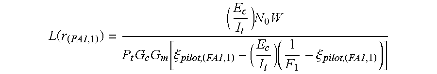
- a mobile station at point P is traveling from cell 100 to cell 200 , where P is a distance r from base station BS 0 and a distance r′ from base station BS 1
- the path loss to BS 0 is designated as L 0 (r)
- the path loss to base station BS 1 is designated as L 1 (r′).
- F 1 is the frequency reuse efficiency at a distance r from base station BS 1 for FA# 1 ,
- P t total base station transmit power
- G C is base station antenna gain including feeder line cable loss
- G M is mobile station antenna gain including feeder line cable loss
- E C is energy per chip code
- I t is total interference as a summation of common cell interference, other cell interference and background noise
- N 0 thermal noise density
- W is channel bandwidth
- ⁇ (pilot(FA1,1) is a ratio of power allocated to the pilot channel for FA# 1 in base station BS 1 relative to the total base station transmit power P t , and
- E C /I t is the strength of the pilot channel signal (for FA# 1 transmitted by base station BS 1 ) received by a mobile station for a pilot channel power allocation ratio of ⁇ pilot(FA1,1) .
- L ⁇ ( r ( FA2 , 1 ) ) ( E c I t ) ⁇ N 0 ⁇ W P t ⁇ G c ⁇ G m ⁇ [ ⁇ pilot , ( FA2 , 1 ) - ( E c I t ) ⁇ ( ⁇ pilot , ( FA2 , 1 ) + ⁇ paging + ⁇ ⁇ ⁇ sync ) ⁇ ( 1 F 2 ) + ( E c I t ) ⁇ ⁇ pilot , ( FA2 , 1 ) ] ( 2 )
- F 2 is the frequency reuse efficiency at a distance r from base station BS 1 for FA# 2 ,
- ⁇ pilot,(FA2,1) is a ratio of power allocated to the pilot channel for FA# 2 in base station BS 1 relative to the total base station transmit power P t .
- E C /I t is the strength of the pilot channel signal (i.e., the dummy pilot signal, which is for FA# 2 transmitted by base station BS 1 ) received by a mobile station for a pilot channel power allocation ratio of ⁇ pilot(FA2,1) , and
- E C /I t is the strength of the dummy pilot channel signal
- the power allocation ratio for the dummy pilot is determined by the threshold value of E C /I t and the values of F 1 and F 2 which suffice to make the handoff-starting area of FA# 2 using the dummy pilot equal to that of FA# 1 .
- ⁇ pilot(FA2,1) can be derived by substituting the values of F 1 and F 2 in eqn. (3) at a position where the value of FA# 1 is the threshold T_ADD. (In CDMA systems, when the RF communication signal power received by a mobile station falls below the threshold T_ADD, the mobile station is reported as a handover candidate.)
- the value of F 2 is varied according to the value of ⁇ pilot(FA2,1) , so the value of F 2 is derived by substituting the value of ⁇ pilot(FA2,1) . Then, repeating the calculation to find the value of ⁇ pilot(FA2,1) derives a convergent value.
- the convergent value of ⁇ pilot(FA2,1) derived from the above calculation is 0.121475 (for the specific case defined by the parameter values below).
- FIG. 2 illustrates a handoff-starting area for the case where the ratio of power allocation for the dummy pilot is 0.15
- FIG. 3 illustrates a handoff-starting area for the case where the ratio of power allocation for the dummy pilot is 0.1215. From the figures, it is seen that for the dummy pilot ratio of 0.1215, the handoff-starting area for FA# 1 (HS FA#1 ) more closely matches the handoff-starting area for FA# 2 (HS FA#2 ) in this example.
- the handoff area of FA# 2 is increased over FA# 1 .
- the handoff-starting area of FA# 2 is consistent with that of FA# 1 .
- step S 2 the path losses of the forward and reverse links are determined in a conventional manner, but using the power allocation ratio for the dummy pilot established in accordance with the above equations (1) ⁇ (3).
- step S 4 the RF power of the outputs at FA# 1 and FA# 2 are measured (when a subscriber does not occupy it) in step S 4 . If the outputs of FA# 1 and FA# 2 are equal in power, the outputs are adjusted by varying the Tx_Atten of FA# 1 and/or FA# 2 (step S 6 ).
- Tx_Atten represents the value of a transmit attenuator at the base station. A different transmit attenuator is used for each frequency allocation.
- the value of Tx_Atten for FA# 2 determines the RF output power of the dummy pilot
- Tx_Atten for FA# 1 determines the RF output power for both the traffic channels and the pilot channel of FA# 1 .
- step S 8 the Tx_Atten value for FA# 2 for each sector in current operation is confirmed.
- the Tx_Atten value for FA# 2 is then adjusted in step S 10 so that the output of the dummy frequency assignment (at FA# 2 ) is less than the output of FA# 1 in accordance with the dummy pilot power allocation ratio, by as much as a predetermined amount, e.g., by about 1 dB.
- the present invention advantageously makes it possible to use available system resources of a common frequency assignment uniformly by determining a power allocation ratio for a dummy pilot sufficient to equalize the coverage of a common FA with the coverage of a dummy FA in multi-FA environments, particularly in two-FA system environments.
Abstract
Description


Claims (13)


Applications Claiming Priority (2)
| Application Number | Priority Date | Filing Date | Title |
|---|---|---|---|
| KR97-79027 | 1997-12-30 | ||
| KR1019970079027A KR100295437B1 (en) | 1997-12-30 | 1997-12-30 | Method for optimizing coverage in a multi frequency assignment system |
Publications (1)
| Publication Number | Publication Date |
|---|---|
| US6188906B1 true US6188906B1 (en) | 2001-02-13 |
Family
ID=19530006
Family Applications (1)
| Application Number | Title | Priority Date | Filing Date |
|---|---|---|---|
| US09/224,233 Expired - Lifetime US6188906B1 (en) | 1997-12-30 | 1998-12-30 | Method for coverage optimization of multi-frequency assignment system |
Country Status (4)
| Country | Link |
|---|---|
| US (1) | US6188906B1 (en) |
| KR (1) | KR100295437B1 (en) |
| CN (1) | CN1112074C (en) |
| AU (1) | AU711867B2 (en) |
Cited By (33)
| Publication number | Priority date | Publication date | Assignee | Title |
|---|---|---|---|---|
| WO2001065870A1 (en) * | 2000-02-29 | 2001-09-07 | Verizon Laboratories Inc. | An iterative system and method for optimizing cdma load distribution |
| US20020086675A1 (en) * | 2000-12-29 | 2002-07-04 | Mansour Nagi A. | Cellular/PCS CDMA system with pilot beacons for call handoffs |
| US20020085523A1 (en) * | 2000-12-29 | 2002-07-04 | Lg Electronics Inc. | Mobile station service in mobile communication system |
| US20020098846A1 (en) * | 2001-01-19 | 2002-07-25 | Hitachi, Ltd. | Base station for wireless communication and method for setting up frequency band in the base station |
| US20030054828A1 (en) * | 2001-07-26 | 2003-03-20 | Dent Paul W. | Communications system employing non-polluting pilot codes |
| US6556551B1 (en) * | 1999-05-27 | 2003-04-29 | Lgc Wireless, Inc. | Multi-frequency pilot beacon for CDMA systems |
| US6611506B1 (en) * | 1999-01-21 | 2003-08-26 | Lucent Technologies Inc. | Enhanced channel allocation among multiple carriers in a spread spectrum communications system |
| WO2003107703A1 (en) * | 2002-06-13 | 2003-12-24 | Telia Ab (Publ) | A cellular mobile telephone network and a procedure to optimize it |
| US6721351B1 (en) * | 1999-03-16 | 2004-04-13 | Samsung Electronics Co., Ltd. | Handoff supporting apparatus and method in CDMA communication system supporting multi-frequency assignment |
| US6731620B1 (en) * | 1999-03-15 | 2004-05-04 | Samsung Electronics Co., Ltd. | Method for optimally allocating channel power in W-CDMA WILL system |
| US20050254465A1 (en) * | 2000-10-25 | 2005-11-17 | Lundby Stein A | Method and apparatus for determining a data rate in a high rate packet data wireless communications system |
| US20060183431A1 (en) * | 2005-02-17 | 2006-08-17 | Henry Chang | Mobile station traffic state antenna tuning systems and methods |
| US20060183443A1 (en) * | 2005-02-17 | 2006-08-17 | Henry Chang | Mobile station access and idle state antenna tuning systems and methods |
| US20060183442A1 (en) * | 2005-02-17 | 2006-08-17 | Henry Chang | Mobile station acquisition state antenna tuning systems and methods |
| US20060276215A1 (en) * | 2005-06-01 | 2006-12-07 | Angel Lozano | Method of allocating power over channels of a communication system |
| US20070010251A1 (en) * | 2005-07-08 | 2007-01-11 | Samsung Electronics., Ltd. | System and method for performing handover between frequency assignments in a communication system |
| US20070025319A1 (en) * | 1997-11-03 | 2007-02-01 | Roberto Padovani | Method and apparatus for high rate packet data transmission |
| US20070099660A1 (en) * | 2005-10-31 | 2007-05-03 | Microsoft Corporation | Dynamic frequency inventory and masking |
| US20080159226A1 (en) * | 2006-12-29 | 2008-07-03 | Lucent Technologies Inc | Methods of handling coverage within a wireless communications system |
| CN100431380C (en) * | 2004-07-09 | 2008-11-05 | 中兴通讯股份有限公司 | Auxiliary carrier signal quality estimating and carrier selecting method for TD-SCDMA system |
| EP2071736A1 (en) | 2007-12-14 | 2009-06-17 | Vodafone Group PLC | Method to improve capacity in a communication network |
| EP2071735A1 (en) | 2007-12-14 | 2009-06-17 | Vodafone Group PLC | Method to improve coverage in a communication network |
| US20090232013A1 (en) * | 2007-05-22 | 2009-09-17 | Nethawk Oyj | Method, measuring system, base station, network element, and measuring device |
| US20100131664A1 (en) * | 2007-03-30 | 2010-05-27 | Andras Veres | Buffer transfer in a communications network |
| US20100323748A1 (en) * | 1997-11-03 | 2010-12-23 | Qualcomm Incorporated | Pilot reference transmission for a wireless communication system |
| US20110069629A1 (en) * | 2009-09-22 | 2011-03-24 | Qualcomm Incorporated | Physical layer metrics to support adaptive station-dependent channel state information feedback rate in multi-user communication systems |
| CN101073278B (en) * | 2004-12-08 | 2011-05-11 | 韩国电子通信研究院 | Method of controlling base stations to suppress inter-cell interference |
| US8064409B1 (en) | 1999-08-25 | 2011-11-22 | Qualcomm Incorporated | Method and apparatus using a multi-carrier forward link in a wireless communication system |
| US8068453B2 (en) | 1999-10-07 | 2011-11-29 | Qualcomm Incorporated | Method and apparatus for predicting favored supplemental channel transmission slots using transmission power measurements of a fundamental channel |
| US8965379B1 (en) | 2013-01-30 | 2015-02-24 | Sprint Spectrum L.P. | Assigning traffic channels to a wireless communication device based on traffic channel utilization |
| US9001811B2 (en) | 2009-05-19 | 2015-04-07 | Adc Telecommunications, Inc. | Method of inserting CDMA beacon pilots in output of distributed remote antenna nodes |
| US9131466B1 (en) | 2012-06-13 | 2015-09-08 | Sprint Spectrum L.P. | Selecting a frequency for a wireless communication device from non-overlapping frequency bands |
| US9426821B2 (en) | 2000-10-25 | 2016-08-23 | Qualcomm Incorporated | Method and apparatus for high rate packet data and low delay data transmissions |
Families Citing this family (8)
| Publication number | Priority date | Publication date | Assignee | Title |
|---|---|---|---|---|
| KR100580829B1 (en) * | 1999-07-08 | 2006-05-16 | 주식회사 케이티프리텔 | A POWER CONTROL METHOD Of A DUMMY FREQUENCY AND A POWER CONTROL DEVICE OF A DUMMY FREQUENCY IN CODE DIVISION MULTIPLE ACCESS TELECOMMUNICATION SYSTEM |
| KR20010084920A (en) * | 2001-04-16 | 2001-09-07 | 변진우 | Method for providing quality of service to support the multimedia communications in the wireless internet environment |
| KR20050054883A (en) * | 2005-04-22 | 2005-06-10 | (주)테노시스 | Method of forward power control by used sector power for ip-bs system |
| JP5617676B2 (en) * | 2010-07-07 | 2014-11-05 | ソニー株式会社 | COMMUNICATION CONTROL DEVICE, COMMUNICATION CONTROL METHOD, COMMUNICATION SYSTEM, AND COMMUNICATION DEVICE |
| PL2453582T3 (en) | 2010-11-16 | 2014-11-28 | Gemalto M2M Gmbh | Detecting of jamming affecting a communication user equipment |
| CN103002553A (en) * | 2011-09-15 | 2013-03-27 | 中兴通讯股份有限公司 | Power calibration method and power calibration device |
| CN113922856B (en) * | 2021-12-14 | 2022-03-18 | 成都航天通信设备有限责任公司 | Method for switching return frequency points of multi-beam satellite mobile communication |
| KR20230094546A (en) | 2021-12-21 | 2023-06-28 | 이숭재 | Spray-type treatment device for pet excrement and pests |
Citations (12)
| Publication number | Priority date | Publication date | Assignee | Title |
|---|---|---|---|---|
| US4639914A (en) * | 1984-12-06 | 1987-01-27 | At&T Bell Laboratories | Wireless PBX/LAN system with optimum combining |
| US5551057A (en) | 1994-06-08 | 1996-08-27 | Lucent Technologies Inc. | Cellular mobile radio system power control |
| US5594718A (en) * | 1995-03-30 | 1997-01-14 | Qualcomm Incorporated | Method and apparatus for providing mobile unit assisted hard handoff from a CDMA communication system to an alternative access communication system |
| US5649000A (en) | 1994-11-16 | 1997-07-15 | Electronics & Telecommunications Research Institute | Method and system for providing a different frequency handoff in a CDMA cellular telephone system |
| US5771461A (en) | 1996-06-28 | 1998-06-23 | Motorola, Inc. | Method and apparatus for power control of a first channel based on a signal quality of a second channel |
| US5771451A (en) | 1995-09-04 | 1998-06-23 | Nec Corporation | Method of transmission power control in a cellular mobile communication system and apparatus thereof |
| US5781861A (en) | 1995-12-06 | 1998-07-14 | Electronics And Telecommunications Research Institute | Method for shedding traffic load in code division multiple access mobile communication system |
| US5859839A (en) * | 1997-06-30 | 1999-01-12 | Motorola, Inc. | Method for automatically selecting channel powers in a wireless communication system |
| US5982759A (en) * | 1996-12-28 | 1999-11-09 | Shinsegi Telecomm, Inc. | Method for generating dummy frequencies for frequency hard handover in code division multiple access mobile communication system |
| US6070075A (en) * | 1997-06-30 | 2000-05-30 | Samsung Electronics Co., Ltd. | Hard handoff method using the dummy pilot |
| US6078571A (en) * | 1997-09-19 | 2000-06-20 | Motorola, Inc. | Apparatus and method for transmitting beacon signals in a communication system |
| US6081714A (en) * | 1997-05-28 | 2000-06-27 | Nec Corporation | Low traffic handoff method for CDMA cellular network using different frequencies among base stations |
Family Cites Families (3)
| Publication number | Priority date | Publication date | Assignee | Title |
|---|---|---|---|---|
| US5692015A (en) * | 1994-06-22 | 1997-11-25 | Ntt Mobile Communications Network, Inc. | Coherent detector and a coherent detection method for a digital communication receiver |
| US5548812A (en) * | 1994-07-21 | 1996-08-20 | Qualcomm Incorporated | Method and apparatus for balancing the forward link handoff boundary to the reverse link handoff boundary in a cellular communication system |
| US5828661A (en) * | 1996-05-22 | 1998-10-27 | Qualcomm Incorporated | Method and apparatus for providing a cone of silence in a cellular communication system |
-
1997
- 1997-12-30 KR KR1019970079027A patent/KR100295437B1/en not_active IP Right Cessation
-
1998
- 1998-12-30 AU AU98243/98A patent/AU711867B2/en not_active Ceased
- 1998-12-30 CN CN98127188A patent/CN1112074C/en not_active Expired - Fee Related
- 1998-12-30 US US09/224,233 patent/US6188906B1/en not_active Expired - Lifetime
Patent Citations (12)
| Publication number | Priority date | Publication date | Assignee | Title |
|---|---|---|---|---|
| US4639914A (en) * | 1984-12-06 | 1987-01-27 | At&T Bell Laboratories | Wireless PBX/LAN system with optimum combining |
| US5551057A (en) | 1994-06-08 | 1996-08-27 | Lucent Technologies Inc. | Cellular mobile radio system power control |
| US5649000A (en) | 1994-11-16 | 1997-07-15 | Electronics & Telecommunications Research Institute | Method and system for providing a different frequency handoff in a CDMA cellular telephone system |
| US5594718A (en) * | 1995-03-30 | 1997-01-14 | Qualcomm Incorporated | Method and apparatus for providing mobile unit assisted hard handoff from a CDMA communication system to an alternative access communication system |
| US5771451A (en) | 1995-09-04 | 1998-06-23 | Nec Corporation | Method of transmission power control in a cellular mobile communication system and apparatus thereof |
| US5781861A (en) | 1995-12-06 | 1998-07-14 | Electronics And Telecommunications Research Institute | Method for shedding traffic load in code division multiple access mobile communication system |
| US5771461A (en) | 1996-06-28 | 1998-06-23 | Motorola, Inc. | Method and apparatus for power control of a first channel based on a signal quality of a second channel |
| US5982759A (en) * | 1996-12-28 | 1999-11-09 | Shinsegi Telecomm, Inc. | Method for generating dummy frequencies for frequency hard handover in code division multiple access mobile communication system |
| US6081714A (en) * | 1997-05-28 | 2000-06-27 | Nec Corporation | Low traffic handoff method for CDMA cellular network using different frequencies among base stations |
| US5859839A (en) * | 1997-06-30 | 1999-01-12 | Motorola, Inc. | Method for automatically selecting channel powers in a wireless communication system |
| US6070075A (en) * | 1997-06-30 | 2000-05-30 | Samsung Electronics Co., Ltd. | Hard handoff method using the dummy pilot |
| US6078571A (en) * | 1997-09-19 | 2000-06-20 | Motorola, Inc. | Apparatus and method for transmitting beacon signals in a communication system |
Cited By (69)
| Publication number | Priority date | Publication date | Assignee | Title |
|---|---|---|---|---|
| US8009625B2 (en) | 1997-11-03 | 2011-08-30 | Qualcomm Incorporated | Method and apparatus for high rate packet data transmission |
| US7848283B2 (en) | 1997-11-03 | 2010-12-07 | Qualcomm Incorporated | Method and apparatus for high rate packet data transmission |
| US20070025319A1 (en) * | 1997-11-03 | 2007-02-01 | Roberto Padovani | Method and apparatus for high rate packet data transmission |
| US8077655B2 (en) | 1997-11-03 | 2011-12-13 | Qualcomm Incorporated | Method and apparatus for high rate packet data transmission |
| US20070066320A1 (en) * | 1997-11-03 | 2007-03-22 | Roberto Padovani | Method and apparatus for high rate packet data transmission |
| US7848285B2 (en) | 1997-11-03 | 2010-12-07 | Qualcomm Incorporated | Method and apparatus for high rate packet data transmission |
| US7995531B2 (en) | 1997-11-03 | 2011-08-09 | Qualcomm Incorporated | Method and apparatus for high rate packet data transmission |
| US8005042B2 (en) | 1997-11-03 | 2011-08-23 | Qualcomm Incorporated | Method and apparatus for high rate packet data transmission |
| US9118387B2 (en) | 1997-11-03 | 2015-08-25 | Qualcomm Incorporated | Pilot reference transmission for a wireless communication system |
| US20090310588A1 (en) * | 1997-11-03 | 2009-12-17 | Qualcomm Incorporated | Method and apparatus for high rate packet data transmission |
| US7848284B2 (en) | 1997-11-03 | 2010-12-07 | Qualcomm Incorporated | Method and apparatus for high rate packet data transmission |
| US20100323748A1 (en) * | 1997-11-03 | 2010-12-23 | Qualcomm Incorporated | Pilot reference transmission for a wireless communication system |
| US7848282B2 (en) | 1997-11-03 | 2010-12-07 | Qualcomm Incorporated | Method and apparatus for high rate packet data transmission |
| US8089924B2 (en) | 1997-11-03 | 2012-01-03 | Qualcomm Incorporated | Method and apparatus for high rate packet data transmission |
| US8189540B2 (en) | 1997-11-03 | 2012-05-29 | Qualcomm Incorporated | Method and apparatus for high rate packet data transmission |
| US8311027B2 (en) | 1997-11-03 | 2012-11-13 | Qualcomm Incorporated | Method and apparatus for high rate packet data transmission |
| US8351372B2 (en) | 1997-11-03 | 2013-01-08 | Qualcomm Incorporated | Method and apparatus for high rate packet data transmission |
| US9124344B2 (en) | 1997-11-03 | 2015-09-01 | Qualcomm Incorporated | Pilot reference transmission for a wireless communication system |
| US9001735B2 (en) | 1997-11-03 | 2015-04-07 | Qualcomm Incorporated | Method and apparatus for high rate packet data transmission |
| US6611506B1 (en) * | 1999-01-21 | 2003-08-26 | Lucent Technologies Inc. | Enhanced channel allocation among multiple carriers in a spread spectrum communications system |
| US6731620B1 (en) * | 1999-03-15 | 2004-05-04 | Samsung Electronics Co., Ltd. | Method for optimally allocating channel power in W-CDMA WILL system |
| US6721351B1 (en) * | 1999-03-16 | 2004-04-13 | Samsung Electronics Co., Ltd. | Handoff supporting apparatus and method in CDMA communication system supporting multi-frequency assignment |
| US6556551B1 (en) * | 1999-05-27 | 2003-04-29 | Lgc Wireless, Inc. | Multi-frequency pilot beacon for CDMA systems |
| US8064409B1 (en) | 1999-08-25 | 2011-11-22 | Qualcomm Incorporated | Method and apparatus using a multi-carrier forward link in a wireless communication system |
| US8068453B2 (en) | 1999-10-07 | 2011-11-29 | Qualcomm Incorporated | Method and apparatus for predicting favored supplemental channel transmission slots using transmission power measurements of a fundamental channel |
| US6512933B1 (en) * | 2000-02-29 | 2003-01-28 | Verizon Laboratories Inc. | Iterative system and method for optimizing CDMA load distribution using reverse interference measurements |
| WO2001065870A1 (en) * | 2000-02-29 | 2001-09-07 | Verizon Laboratories Inc. | An iterative system and method for optimizing cdma load distribution |
| US9426821B2 (en) | 2000-10-25 | 2016-08-23 | Qualcomm Incorporated | Method and apparatus for high rate packet data and low delay data transmissions |
| US20050254465A1 (en) * | 2000-10-25 | 2005-11-17 | Lundby Stein A | Method and apparatus for determining a data rate in a high rate packet data wireless communications system |
| US9107109B2 (en) | 2000-10-25 | 2015-08-11 | Qualcomm Incorporated | Method and apparatus for determining a data rate in a high rate packet data wireless communications system |
| US6973098B1 (en) * | 2000-10-25 | 2005-12-06 | Qualcomm, Incorporated | Method and apparatus for determining a data rate in a high rate packet data wireless communications system |
| US7161918B2 (en) * | 2000-12-29 | 2007-01-09 | Lg-Nortel Co., Ltd. | Mobile station service in mobile communication system |
| US20020086675A1 (en) * | 2000-12-29 | 2002-07-04 | Mansour Nagi A. | Cellular/PCS CDMA system with pilot beacons for call handoffs |
| US6901256B2 (en) * | 2000-12-29 | 2005-05-31 | Sprint Spectrum L.P. | Cellular/PCS CDMA system with pilot beacons for call handoffs |
| US20020085523A1 (en) * | 2000-12-29 | 2002-07-04 | Lg Electronics Inc. | Mobile station service in mobile communication system |
| US20020098846A1 (en) * | 2001-01-19 | 2002-07-25 | Hitachi, Ltd. | Base station for wireless communication and method for setting up frequency band in the base station |
| US20020098870A1 (en) * | 2001-01-19 | 2002-07-25 | Kenji Kashiwagi | Base station for wireless communication and method for setting up frequency band in the base station |
| US7133378B2 (en) * | 2001-01-19 | 2006-11-07 | Hitachi, Ltd. | Base station for wireless communication and method for setting up frequency band in the base station |
| US20030054828A1 (en) * | 2001-07-26 | 2003-03-20 | Dent Paul W. | Communications system employing non-polluting pilot codes |
| US7224942B2 (en) * | 2001-07-26 | 2007-05-29 | Telefonaktiebolaget Lm Ericsson (Publ) | Communications system employing non-polluting pilot codes |
| WO2003107703A1 (en) * | 2002-06-13 | 2003-12-24 | Telia Ab (Publ) | A cellular mobile telephone network and a procedure to optimize it |
| CN100431380C (en) * | 2004-07-09 | 2008-11-05 | 中兴通讯股份有限公司 | Auxiliary carrier signal quality estimating and carrier selecting method for TD-SCDMA system |
| CN101073278B (en) * | 2004-12-08 | 2011-05-11 | 韩国电子通信研究院 | Method of controlling base stations to suppress inter-cell interference |
| US20060183443A1 (en) * | 2005-02-17 | 2006-08-17 | Henry Chang | Mobile station access and idle state antenna tuning systems and methods |
| US7796963B2 (en) | 2005-02-17 | 2010-09-14 | Kyocera Corporation | Mobile station acquisition state antenna tuning systems and methods |
| US7577411B2 (en) | 2005-02-17 | 2009-08-18 | Kyocera Corporation | Mobile station access and idle state antenna tuning systems and methods |
| US20060183431A1 (en) * | 2005-02-17 | 2006-08-17 | Henry Chang | Mobile station traffic state antenna tuning systems and methods |
| US20060183442A1 (en) * | 2005-02-17 | 2006-08-17 | Henry Chang | Mobile station acquisition state antenna tuning systems and methods |
| US8396431B2 (en) | 2005-02-17 | 2013-03-12 | Kyocera Corporation | Mobile station traffic state antenna tuning systems and methods |
| US20060276215A1 (en) * | 2005-06-01 | 2006-12-07 | Angel Lozano | Method of allocating power over channels of a communication system |
| US7489944B2 (en) * | 2005-06-01 | 2009-02-10 | Alcatel-Lucent Usa Inc. | Method of allocating power over channels of a communication system |
| US20070010251A1 (en) * | 2005-07-08 | 2007-01-11 | Samsung Electronics., Ltd. | System and method for performing handover between frequency assignments in a communication system |
| US20070099660A1 (en) * | 2005-10-31 | 2007-05-03 | Microsoft Corporation | Dynamic frequency inventory and masking |
| US7983686B2 (en) | 2005-10-31 | 2011-07-19 | Microsoft Corporation | Dynamic frequency inventory and masking |
| WO2007053664A1 (en) * | 2005-10-31 | 2007-05-10 | Microsoft Corporation | Dynamic frequency inventory and masking |
| US20080159226A1 (en) * | 2006-12-29 | 2008-07-03 | Lucent Technologies Inc | Methods of handling coverage within a wireless communications system |
| WO2008082481A1 (en) * | 2006-12-29 | 2008-07-10 | Lucent Technologies Inc. | Methods of handling coverage within a wireless communications system |
| US8848654B2 (en) * | 2006-12-29 | 2014-09-30 | Alcatel Lucent | Methods of handling coverage within a wireless communications system |
| US8175059B2 (en) * | 2007-03-30 | 2012-05-08 | Telefonaktiebolaget Lm Ericsson (Publ) | Buffer transfer in a communications network |
| US20100131664A1 (en) * | 2007-03-30 | 2010-05-27 | Andras Veres | Buffer transfer in a communications network |
| US8155079B2 (en) * | 2007-05-22 | 2012-04-10 | Nethawk Oyj | Method, measuring system, base station, network element, and measuring device |
| US20090232013A1 (en) * | 2007-05-22 | 2009-09-17 | Nethawk Oyj | Method, measuring system, base station, network element, and measuring device |
| EP2071735A1 (en) | 2007-12-14 | 2009-06-17 | Vodafone Group PLC | Method to improve coverage in a communication network |
| EP2071736A1 (en) | 2007-12-14 | 2009-06-17 | Vodafone Group PLC | Method to improve capacity in a communication network |
| US9001811B2 (en) | 2009-05-19 | 2015-04-07 | Adc Telecommunications, Inc. | Method of inserting CDMA beacon pilots in output of distributed remote antenna nodes |
| US8811200B2 (en) | 2009-09-22 | 2014-08-19 | Qualcomm Incorporated | Physical layer metrics to support adaptive station-dependent channel state information feedback rate in multi-user communication systems |
| US20110069629A1 (en) * | 2009-09-22 | 2011-03-24 | Qualcomm Incorporated | Physical layer metrics to support adaptive station-dependent channel state information feedback rate in multi-user communication systems |
| US9131466B1 (en) | 2012-06-13 | 2015-09-08 | Sprint Spectrum L.P. | Selecting a frequency for a wireless communication device from non-overlapping frequency bands |
| US8965379B1 (en) | 2013-01-30 | 2015-02-24 | Sprint Spectrum L.P. | Assigning traffic channels to a wireless communication device based on traffic channel utilization |
Also Published As
| Publication number | Publication date |
|---|---|
| CN1233141A (en) | 1999-10-27 |
| CN1112074C (en) | 2003-06-18 |
| AU9824398A (en) | 1999-07-22 |
| KR19990058853A (en) | 1999-07-26 |
| KR100295437B1 (en) | 2001-07-12 |
| AU711867B2 (en) | 1999-10-21 |
Similar Documents
| Publication | Publication Date | Title |
|---|---|---|
| US6188906B1 (en) | Method for coverage optimization of multi-frequency assignment system | |
| EP0569559B1 (en) | Improved gsm interference band selection and reduced power handover | |
| AU730099B2 (en) | Method for optimising forward link coverage in a CDMA network | |
| AU754550B2 (en) | Frequency plan revision within a cellular telephone system | |
| RU2117396C1 (en) | Method for making decision on switching communication from one communication resource to another | |
| KR100511144B1 (en) | Method and apparatus for estimating pilot coverages | |
| EP0817400B1 (en) | Method of controlling power on forward link in a cellular CDMA system | |
| KR100236811B1 (en) | Channel assigning method in mobile terminal | |
| US6584325B1 (en) | Subscriber unit and method of cell selection for a cellular communication system | |
| KR100376410B1 (en) | Intra-cell handover method with antenna array | |
| US6473614B1 (en) | Method and means for determining a handover in a radio communication system | |
| US7493087B2 (en) | Apparatus and method of radio access management for a radio communication system | |
| JP2003529962A (en) | Method and apparatus for beamforming in a wireless communication system | |
| US6112082A (en) | Method and an arrangement relating to telecommunications system | |
| US20090059861A1 (en) | Blind handover using load compensated measurements | |
| US7167681B2 (en) | Antenna adjustment method, system and network element | |
| US7319883B2 (en) | Method and apparatus for determining a transmit power | |
| JP2921739B2 (en) | Call admission control method and apparatus | |
| US6618598B1 (en) | Forward rate determination of high data rate channels in CDMA air interface | |
| GB2391755A (en) | Apparatus and method for cell selection in mobile communcation system. | |
| JP2004088207A (en) | Cdma base station apparatus | |
| KR19990058815A (en) | Optimization of Reverse Link Service Zones for Code Division Multiple Access Networks | |
| KR20030056133A (en) | Method for coverage optimum of forwarding link inter network | |
| EP1021923A1 (en) | A method and an arrangement relating to telecommunications systems |
Legal Events
| Date | Code | Title | Description |
|---|---|---|---|
| AS | Assignment |
Owner name: SAMSUNG ELECTRONICS CO., LTD., KOREA, REPUBLIC OF Free format text: ASSIGNMENT OF ASSIGNORS INTEREST;ASSIGNORS:LIM, YOUNG-SIK;WEE, PYEONG-HWAN;REEL/FRAME:009687/0742 Effective date: 19981223 |
|
| FEPP | Fee payment procedure |
Free format text: PAYOR NUMBER ASSIGNED (ORIGINAL EVENT CODE: ASPN); ENTITY STATUS OF PATENT OWNER: LARGE ENTITY |
|
| STCF | Information on status: patent grant |
Free format text: PATENTED CASE |
|
| FPAY | Fee payment |
Year of fee payment: 4 |
|
| FPAY | Fee payment |
Year of fee payment: 8 |
|
| FEPP | Fee payment procedure |
Free format text: PAYER NUMBER DE-ASSIGNED (ORIGINAL EVENT CODE: RMPN); ENTITY STATUS OF PATENT OWNER: LARGE ENTITY Free format text: PAYOR NUMBER ASSIGNED (ORIGINAL EVENT CODE: ASPN); ENTITY STATUS OF PATENT OWNER: LARGE ENTITY |
|
| FPAY | Fee payment |
Year of fee payment: 12 |