US6150936A - Method and system for analyzing received signal strength - Google Patents
Method and system for analyzing received signal strength Download PDFInfo
- Publication number
- US6150936A US6150936A US09/141,232 US14123298A US6150936A US 6150936 A US6150936 A US 6150936A US 14123298 A US14123298 A US 14123298A US 6150936 A US6150936 A US 6150936A
- Authority
- US
- United States
- Prior art keywords
- information
- stored
- signal
- rssi
- memory location
- Prior art date
- Legal status (The legal status is an assumption and is not a legal conclusion. Google has not performed a legal analysis and makes no representation as to the accuracy of the status listed.)
- Expired - Lifetime
Links
Images
Classifications
-
- G—PHYSICS
- G08—SIGNALLING
- G08B—SIGNALLING OR CALLING SYSTEMS; ORDER TELEGRAPHS; ALARM SYSTEMS
- G08B25/00—Alarm systems in which the location of the alarm condition is signalled to a central station, e.g. fire or police telegraphic systems
- G08B25/01—Alarm systems in which the location of the alarm condition is signalled to a central station, e.g. fire or police telegraphic systems characterised by the transmission medium
- G08B25/10—Alarm systems in which the location of the alarm condition is signalled to a central station, e.g. fire or police telegraphic systems characterised by the transmission medium using wireless transmission systems
-
- G—PHYSICS
- G08—SIGNALLING
- G08B—SIGNALLING OR CALLING SYSTEMS; ORDER TELEGRAPHS; ALARM SYSTEMS
- G08B29/00—Checking or monitoring of signalling or alarm systems; Prevention or correction of operating errors, e.g. preventing unauthorised operation
- G08B29/12—Checking intermittently signalling or alarm systems
- G08B29/123—Checking intermittently signalling or alarm systems of line circuits
Definitions
- the present invention relates to communications devices and protocols such as those used in wireless alarm systems having multiple sensors in communication with one or more receiver/controller units; and in particular to such alarm systems wherein the receiving unit of the system automatically provides an indication as to the signal strength of a received signal by measuring the signal strength of the signal and comparing it against a threshold.
- Radio frequency (RF) wireless security systems available today, such as those manufactured by ADEMCO, generally employ a multiplicity of transmitter products which transmit information to a common receiver/controller.
- the information transmitted typically describes the state of various transducers associated with each transmitter, such as smoke, motion, breaking glass, shock and vibration detectors; door, window and floor mat switches, etc.
- Each signal has a unique identification code embedded in its data message, which serves to identify to the system controller which particular transmitting device has sent that message.
- the present invention is a method for automatically testing a communications system, the communications system comprising a plurality of remote transmitting devices and a receiving station having a receiver associated therewith.
- the receiving station receives a signal from a transmitting device, generates Received Signal Strength Indication (RSSI) data indicative of the signal strength of the received signal, and determines the ID of the transmitting device.
- RSSI Received Signal Strength Indication
- the receiver retrieves stored signal information from a memory location associated with the ID, and compares the stored signal information with the RSSI data. When the comparison is unfavorable, a trouble condition is indicated.
- the stored signal information is tolerance compensated by subtracting a predetermined value from the stored signal information.
- the stored signal information is compared to a processed RSSI data.
- the processed RSSI data may be a running average of the RSSI signal information and prior processed RSSI data stored in a memory location associated with the ID of the transmitting device.
- the method further comprises an install mode wherein the stored signal information in memory is determined.
- the stored signal information is RSSI data indicative of the initial signal strength of the received signal from a transmitting device.
- the install mode is typically entered during system installation, but may also be used to update the stored signal information in memory when necessary, e.g., installation of new transmitter.
- the receiver receives the ID of the transmitting device from the installer, via keypad input, and stores the RSSI data in a location associated with the ID.
- the stored RSSI data may be an average of a number of RSSI data received during the install mode. If the stored signal information is not determined during installation, it may be programmed into memory at the factory during manufacturing, at the site by the installer or at the site by a download from a central station.
- indicating a trouble condition is simply updating a user-interface visual display.
- indicating a trouble condition comprises the steps of processing information stored in a memory location associated with the ID and updating a user-interface visual display. The processing of the information may include increasing the count stored in a memory location associated with the ID, checking if it is greater than a predetermined count and when it is greater, updating a user-interface visual display.
- the count stored in a memory location associated with the ID is reset when the tolerance compensated signal level is less than the RSSI signal information.
- indicating a trouble condition is the action of dialing up a central station.
- a message is transmitted to the alarm system dialer by the processor/transmitter and the dialer transmits the trouble condition message to a central station.
- dialing the central station may be delayed a short period of time to allow an on-site person to fix the trouble condition prior to alerting the central alarm station.
- alerting the central alarm station of the trouble condition may be considered a backup to other trouble indication methods.
- the present invention is implemented by a system comprising a self-testing data communications system comprising a plurality of remote devices, each of the remote devices comprising means for transmitting signals, wherein the signals include an ID associated with the remote device, and a receiving station.
- the receiving station comprises means for receiving signals, means for generating an RSSI data indicative of the signal strength of the received signal, means for determining the remote device ID, storage means for signal information associated with the remote device ID, comparison means for comparing RSSI data to the stored signal information, processing means for determining the trouble condition set forth from above comparison, and indication means for indicating a trouble condition set forth from above comparison.
- the system further comprises means for initiating an install mode wherein a number of transmissions from each of the remote devices causes an average of the RSSI data to be determined and stored in the storage means at a location associated with the ID of the remote device.
- the remote devices communicate with the receiver by electromagnetic wave transmission which may be radio frequency.
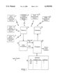
- FIG. 1 is a block diagram of the preferred embodiment of the present invention
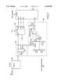
- FIG. 2 is a detailed schematic of the video processing portion of the block diagram of FIG. 1;
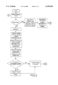
- FIG. 3 is a flow chart of the operation of the preferred embodiment of the present invention.
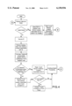
- FIG. 4 is a flow chart of the operation of an alternative embodiment of the present invention.
- an alarm system 2 is shown. Included is a receiver 14 and a transmitter 16 in communication with a plurality of alarm sensor/transmitter devices 4, a wireless console transceiver device 8, a siren transceiver device 10, and a dialer transceiver device 12.
- the alarm sensors 4 include, for example, motion detectors, fire or smoke sensors, glass breakage sensors, door or window entry sensors, and the like.
- the alarm system 2 operates in a so-called wireless fashion by electromagnetic wave transmission (radio frequency in particular) between the devices 4, 8, 10, and 12 and the receiver 14 and transmitter 16.
- the alarm sensor/transmitter devices 4, wireless console transceiver device 8, siren transceiver device 10, and dialer transceiver device 12 are well known in the art and are not described in detail.
- a transmitting device transmits signals by modulating a high frequency RF signal (e.g., 345 MHz) which typically contains data, status, preamble, cyclic redundancy check data and the identification data (ID) of the transmitting device.
- the modulated RF signal is received by the receiver 14.
- the receiver 14 may comprise the following: an antenna selection circuit, an RF filter, a low noise amplifier, a second RF filter, a mixer, a local oscillator, an IF filter, an IF gain and demodulation circuit, and a video filter.
- Data formats and receiver circuits are all well known to one skilled in the art and are not described in further detail here.
- the receiver 14 output is then processed by video processing 18, which provides two digital signals to the processor, data and a received signal strength indication (RSSI).
- the processor decodes the data signal and determines which action should be taken; e.g., if an alarm condition is indicated, then the transmitter 16 may transmit a command to the wireless console transceiver device 8, the siren transceiver device 10, and/or the dialer transceiver device. These actions are well known in the art and are not described here.
- the present invention is based on the ability to monitor the power level of the received signal. This is done prior to processing the data signal.
- An RSSI measurement circuit shown as video processing 18, measures the signal strength of the received signal and provides a digital output to the processor 20. RSSI measurement circuits are well known in the art, as set forth for example in U.S. Pat. Nos. 4,620,114; 5,390,365; and 5,423,064.
- the processor 20 inputs the RSSI data and compares it to a threshold located in a look-up table in EEPROM 24. If the comparison is unfavorable, a trouble condition is then indicated on the control panel, typically in the form of a visual display. It would be apparent to one skilled in the art that this may be any form of visual display or that the indication of trouble may be in the form of alerting a central station.
- the look-up table in EEPROM 24 is programmed during installation with the identity of each device and an average of a number of RSSI data from the device at installation.
- the installer enters the install command at the wireless console 8. He then keys in the ID of a transmitter device (4, 8, 10 or 12) at the wireless console 8 and initiates the transmitter device (4, 8, 10 and 12) to send a number of messages to the receiver 14.
- the processor 20 determines the average of the RSSI data from the transmitter device (4, 8, 10 or 12) and stores it in a memory location associated with the ID. The installer will do this for each transmitter device (4, 8, 10 or 12).
- FIG. 1 shows a representation of the look-up table, wherein the ID has two memory locations associated with it.
- one memory location contains the installed signal level described above, and the second memory location contains a value used to determine if a trouble condition should be indicated.
- This second location may contain historical data correlated to prior measured RSSI levels; for example, it may contain a running average of the RSSI of the data.
- a running average could be calculated, for example, by determining the average between the current RSSI value and the stored value, and storing that running average back into the memory. In this case, a trouble condition would be indicated if the running average went below a predetermined level (which may be the installed level plus or minus a tolerance function).
- the visual display may be updated as a direct result.
- the intelligent processing of this embodiment will allow the system to determine if a deleterious or fading condition truly exists, and then indicate the trouble condition to a user via the display.
- the system will not indicate the deleterious or fading condition to the us er via the display until a trouble condition occurs for a predefined consecutive number of times.
- the second memory location may contain a count. In this case, the number of consecutive times that the RSSI data is below the installed level (within some tolerance) is counted. When this count exceeds a predetermined amount, than a trouble condition is indicated.
- the predetermined level for the average comparison, the predetermined amount for the count comparison, and the tolerance for the RSSI data comparison may be set during manufacture, onsite by the installer, or downloaded from the central station. These levels may be different for each transmitter, ie fire and smoke would need a more stringent test than a door opener would. It would be apparent to one skilled in the art that any number of memory locations may be associated with each ID and the memory locations may contain various information needed by different routines for processing of information necessary to monitor the power of the received signal.
- FIG. 2 is a detailed circuit diagram of the video processing circuit 18 in FIG. 1.
- IF/demodulator integrated circuit 34 which in the preferred embodiment is a Philips NE614, utilizes the IF input signal and provides at its output a demodulated data signal to the low pass filter 36 formed by R1 and C1.
- the low pass filter 36 redu ces the noise content of the video output signal.
- the filtered video signal is then AC coupled via capacitor C2 to the non-inverting input of the U3 comparator (LM339), which quantizes the signal to a logic level suitable for input to the processor 20.
- the combination of R4 and R5 form a voltage divider, which sets a slicing level for the reference voltage applied to the inverting input to the U3 comparator.
- Capacitor C3 provides an AC ground for the U3 comparator reference input.
- the output signal of comparator U3 is input to I3 of the processor 20.
- the processor in the preferred embodiment is a COP881 available from National Semiconductor.
- the output from U3 is fed to port I3 of the processor.
- the filtered demodulated data signal is also input to an analog-to-digital (A/D) circuit 40, which provides a digital output representative of the input signal level (RSSI) in accordance with techniques well known in the art.
- A/D analog-to-digital
- RSSI input signal level
- a Texas Instruments TLC549I is used.
- a serial digital data word is then input to the port G5 of the processor 20 for storage in EEPROM 24 and subsequent analysis as described below.
- FIG. 3 is the first embodiment of the present invention
- FIG. 4 contains a second embodiment of the present invention.
- the received signal is processed by the aforementioned RF components, producing the data signal and the RSSI signal.
- the processor determines if the alarm system is in install mode. If the system is in install mode, then the RSSI data is stored in the installed level memory location and the Ave (Average) memory location in the EEPROM 24 at a location associated with the ID. If the alarm system is still in install mode when additional RSSI data is received, an average of the first RSSI data and the additional RSSI data is stored in both the installed level and Ave memory locations.
- the processor 20 decodes the ID bits of the data signal at I3 and retrieves installed level and Ave from memory locations associated with the ID. Ave is updated (by adding RSSI data and dividing by 2) with the current RSSI signal and a tolerance compensated level is calculated by subtracting a predetermined value X from the installed level. The tolerance compensated installed level is compared with Ave and if the tolerance compensated installed level is greater than Ave, a trouble condition is indicated on the front panel. In both instances, normal processing of the received signal takes place.
- X may be ascertained in various ways.
- X may be preset at the factory by typical programming techniques.
- X may be programmed by the system installer, who may take measurements during initial operation of the system to determine the proper amount to use in accordance with the particular environment.
- the processor may be configured with techniques known in the art to make certain measurements of received signals, and determine an X to use accordingly.
- the value of X maybe downloaded by the central alarm station.
- the received signal is processed by the aforementioned RF components, producing the data signal and the RSSI signal.
- the processor determines if the alarm system is in install mode. If the system is in install mode, then the RSSI data is stored in the installed level memory location in the EEPROM 24 at a location associated with the ID and the count memory location also associated with the ID is cleared. If the alarm system is still in install mode when additional RSSI data is received, an average of the first RSSI data and the additional RSSI data is stored in the installed level memory location.
- the processor 20 decodes the ID bits of the data signal at I3 and retrieves the stored installed level from a memory location associated with the ID.
- the processor generates a tolerance compensated installed level by subtracting X from the installed level.
- the processor compares the tolerance compensated installed level with the RSSI data. If the tolerance compensated installed level is not greater than the RSSI data, then the count stored in a memory location associated with the ID is reset, and normal processing of the signal continues. If however, the tolerance compensated installed level is greater than the current RSSI data, then the count stored in the memory location associated with the ID is increased by one. The count is then checked to see if it is greater than n (where n may equal 4, for example) and if it is, a trouble condition is indicated on the front panel. In both instances, normal processing of the received signal takes place.
- X may be ascertained in various ways.
- X may be preset at the factory by typical programming techniques.
- X may be programmed by the system installer, who may take measurements during initial operation of the system to determine the proper amount to use in accordance with the particular environment.
- the processor may be configured with techniques known in the art to make certain measurements of received signals, and determine an average noise threshold to use accordingly.
- the value of X maybe downloaded by the central alarm station.
Abstract
Description
Claims (21)
Priority Applications (1)
| Application Number | Priority Date | Filing Date | Title |
|---|---|---|---|
| US09/141,232 US6150936A (en) | 1996-05-20 | 1998-08-27 | Method and system for analyzing received signal strength |
Applications Claiming Priority (3)
| Application Number | Priority Date | Filing Date | Title |
|---|---|---|---|
| US08/650,292 US5828300A (en) | 1996-05-20 | 1996-05-20 | Alarm system with supervision controlled receiver parameter modification |
| US08/685,539 US5801626A (en) | 1996-05-20 | 1996-07-24 | Alarm communications system with supervision signal RSSI analysis |
| US09/141,232 US6150936A (en) | 1996-05-20 | 1998-08-27 | Method and system for analyzing received signal strength |
Related Parent Applications (1)
| Application Number | Title | Priority Date | Filing Date |
|---|---|---|---|
| US08/685,539 Continuation-In-Part US5801626A (en) | 1996-05-20 | 1996-07-24 | Alarm communications system with supervision signal RSSI analysis |
Publications (1)
| Publication Number | Publication Date |
|---|---|
| US6150936A true US6150936A (en) | 2000-11-21 |
Family
ID=46255120
Family Applications (1)
| Application Number | Title | Priority Date | Filing Date |
|---|---|---|---|
| US09/141,232 Expired - Lifetime US6150936A (en) | 1996-05-20 | 1998-08-27 | Method and system for analyzing received signal strength |
Country Status (1)
| Country | Link |
|---|---|
| US (1) | US6150936A (en) |
Cited By (69)
| Publication number | Priority date | Publication date | Assignee | Title |
|---|---|---|---|---|
| US6507277B2 (en) | 2000-10-10 | 2003-01-14 | Job Lizenz Gmbh & Co. Kg | Danger signalling system |
| US20030020611A1 (en) * | 1996-05-30 | 2003-01-30 | Script Michael H. | Portable motion detector and alarm system and method |
| US20040002367A1 (en) * | 2002-06-28 | 2004-01-01 | Nokia Corporation | Pre-resource checking before file download |
| US6696967B1 (en) * | 1998-10-07 | 2004-02-24 | Nicholas Alexander Rutter | Ambient condition alarm for connecting to a light fixture |
| US20040113778A1 (en) * | 1996-05-30 | 2004-06-17 | Script Michael H. | Portable motion detector and alarm system and method |
| US20040150521A1 (en) * | 2003-02-03 | 2004-08-05 | Stilp Louis A. | RFID based security system |
| US20040160324A1 (en) * | 2003-02-03 | 2004-08-19 | Stilp Louis A. | Controller for a security system |
| US20040212494A1 (en) * | 2003-02-03 | 2004-10-28 | Stilp Louis A. | Cordless telephone system |
| US20040215750A1 (en) * | 2003-04-28 | 2004-10-28 | Stilp Louis A. | Configuration program for a security system |
| US20040212493A1 (en) * | 2003-02-03 | 2004-10-28 | Stilp Louis A. | RFID reader for a security network |
| US20040212500A1 (en) * | 2003-02-03 | 2004-10-28 | Stilp Louis A. | RFID based security network |
| US20040258248A1 (en) * | 2003-06-18 | 2004-12-23 | Schnitta Bonnie S. | Sound focusing mechanism and method of estimating acoustic leakage of an object and method of estimating transmission loss of an object |
| US20050021767A1 (en) * | 2001-08-13 | 2005-01-27 | Hong Cai | Keeping persistency while switching between modalities |
| US20050030179A1 (en) * | 1996-05-30 | 2005-02-10 | Script Michael H. | Portable motion detector and alarm system and method |
| US20050079831A1 (en) * | 2003-10-09 | 2005-04-14 | International Business Machines Corporation | Signal strength indicator for a wireless card |
| US20050245195A1 (en) * | 2000-06-03 | 2005-11-03 | Ebox Usa Inc. | Computerized recording and notification of the delivery and pickup of retail goods |
| US6963731B2 (en) * | 2002-09-27 | 2005-11-08 | Zyxel Communications Corporation | Signal strength display device for wireless hub |
| US20050275524A1 (en) * | 2004-06-10 | 2005-12-15 | The Chamberlain Group, Inc. | Access control system wireless transmission link test method |
| US7026948B1 (en) | 1999-03-25 | 2006-04-11 | Runner & Sprue Limited | Alarm with removable detection circuitry cartridge |
| US20060082461A1 (en) * | 2004-10-18 | 2006-04-20 | Walter Kidde Portable Equipment, Inc. | Gateway device to interconnect system including life safety devices |
| US7057512B2 (en) | 2003-02-03 | 2006-06-06 | Ingrid, Inc. | RFID reader for a security system |
| US20060135188A1 (en) * | 2004-11-30 | 2006-06-22 | Murty Ravi A | Interference adaptation apparatus, systems, and methods |
| US7079034B2 (en) | 2003-02-03 | 2006-07-18 | Ingrid, Inc. | RFID transponder for a security system |
| US7079020B2 (en) | 2003-02-03 | 2006-07-18 | Ingrid, Inc. | Multi-controller security network |
| US20060168308A1 (en) * | 2004-11-30 | 2006-07-27 | International Business Machines Corporation | Selective suspension of real time data exchanges for unreliable network connections |
| US7091827B2 (en) | 2003-02-03 | 2006-08-15 | Ingrid, Inc. | Communications control in a security system |
| US7119658B2 (en) | 2003-02-03 | 2006-10-10 | Ingrid, Inc. | Device enrollment in a security system |
| US20070041036A1 (en) * | 2005-08-18 | 2007-02-22 | Kabushiki Kaisha Toshiba | Image forming apparatus |
| WO2007042610A1 (en) * | 2005-10-11 | 2007-04-19 | Telcont Oy | A device, method and system for improving the transmission reliability of an alarm in an alarm system |
| US20070205887A1 (en) * | 2006-03-05 | 2007-09-06 | Ming-Pao Cho | Initiative alarm system |
| US7283048B2 (en) | 2003-02-03 | 2007-10-16 | Ingrid, Inc. | Multi-level meshed security network |
| CN100343833C (en) * | 2001-07-19 | 2007-10-17 | 讯宝科技公司 | Cord-less recognizing safeguard system and method |
| US20070296576A1 (en) * | 2006-06-21 | 2007-12-27 | Mednovus, Inc. | Radio frequency warning system for ferromagnetic threats |
| EP1953720A1 (en) | 2007-02-05 | 2008-08-06 | Elkron S.p.A. | Method and system for evaluating the quality of a radio connection between two wireless devices |
| US7495544B2 (en) | 2003-02-03 | 2009-02-24 | Ingrid, Inc. | Component diversity in a RFID security network |
| US7511614B2 (en) | 2003-02-03 | 2009-03-31 | Ingrid, Inc. | Portable telephone in a security network |
| US7532114B2 (en) | 2003-02-03 | 2009-05-12 | Ingrid, Inc. | Fixed part-portable part communications network for a security network |
| US20090201820A1 (en) * | 2007-12-31 | 2009-08-13 | Honeywell International Inc. | Method for predicting a fault in a security system |
| US7596372B2 (en) | 2004-06-14 | 2009-09-29 | Warren Phillip D | Apparatuses and methods for measuring signal strengths of wireless networks |
| WO2010003408A1 (en) * | 2008-07-08 | 2010-01-14 | Hochschule Ostwestfahlen-Lippe | Method for monitoring a space by means of radio signal-transmitting sensors |
| US7650425B2 (en) | 1999-03-18 | 2010-01-19 | Sipco, Llc | System and method for controlling communication between a host computer and communication devices associated with remote devices in an automated monitoring system |
| US7660591B1 (en) * | 2005-09-09 | 2010-02-09 | Avaya Inc. | Propagation loss model based indoor wireless location of stations |
| US20100081392A1 (en) * | 2006-07-03 | 2010-04-01 | Fabien Rousseau | Method of Communicating by Radio Frequencies in a Home-Automation Installation |
| US7697492B2 (en) | 1998-06-22 | 2010-04-13 | Sipco, Llc | Systems and methods for monitoring and controlling remote devices |
| US7756086B2 (en) | 2004-03-03 | 2010-07-13 | Sipco, Llc | Method for communicating in dual-modes |
| US20100302025A1 (en) * | 2009-05-26 | 2010-12-02 | Script Michael H | Portable Motion Detector And Alarm System And Method |
| EP2264681A1 (en) * | 2008-03-24 | 2010-12-22 | Hochiki Corporation | Alarm |
| US20110057794A1 (en) * | 2008-05-08 | 2011-03-10 | Hochiki Corporation | Alarm |
| US8000314B2 (en) | 1996-12-06 | 2011-08-16 | Ipco, Llc | Wireless network system and method for providing same |
| US8013732B2 (en) | 1998-06-22 | 2011-09-06 | Sipco, Llc | Systems and methods for monitoring and controlling remote devices |
| US8031650B2 (en) | 2004-03-03 | 2011-10-04 | Sipco, Llc | System and method for monitoring remote devices with a dual-mode wireless communication protocol |
| US8064412B2 (en) | 1998-06-22 | 2011-11-22 | Sipco, Llc | Systems and methods for monitoring conditions |
| US8171136B2 (en) | 2001-10-30 | 2012-05-01 | Sipco, Llc | System and method for transmitting pollution information over an integrated wireless network |
| NL2006386C2 (en) * | 2011-03-14 | 2012-09-17 | Astrea Intellectueel Eigendomsrecht B V | Device for testing the integrity of a signalling line. |
| EP2503527A1 (en) * | 2011-03-23 | 2012-09-26 | Hekatron Vertriebs GmbH | Communication system, in particular for alarms and method for its operation |
| US8410931B2 (en) | 1998-06-22 | 2013-04-02 | Sipco, Llc | Mobile inventory unit monitoring systems and methods |
| US8489063B2 (en) | 2001-10-24 | 2013-07-16 | Sipco, Llc | Systems and methods for providing emergency messages to a mobile device |
| GB2502974A (en) * | 2012-06-11 | 2013-12-18 | Tunstall Group Ltd | Identifying RF interference in a social alarm system |
| US8665084B2 (en) | 2011-07-29 | 2014-03-04 | Adt Us Holdings, Inc. | Security system and method |
| US8666357B2 (en) | 2001-10-24 | 2014-03-04 | Sipco, Llc | System and method for transmitting an emergency message over an integrated wireless network |
| US20140098802A1 (en) * | 2012-10-05 | 2014-04-10 | Honeywell International Inc. | Systems and methods of fast wireless output device activation in a mesh network system |
| US8787246B2 (en) | 2009-02-03 | 2014-07-22 | Ipco, Llc | Systems and methods for facilitating wireless network communication, satellite-based wireless network systems, and aircraft-based wireless network systems, and related methods |
| US9146152B2 (en) | 2003-06-18 | 2015-09-29 | Noiseout Inc | Method of estimating acoustic or thermal leakage of an object and method of estimating transmission loss of an object, using a sound focusing mechanism |
| US9439126B2 (en) | 2005-01-25 | 2016-09-06 | Sipco, Llc | Wireless network protocol system and methods |
| US20190088109A1 (en) * | 2017-09-18 | 2019-03-21 | Tyco Fire & Security Gmbh | Method and Apparatus for Verifying Service of Installed Devices Using RFID |
| US10681667B2 (en) | 2017-09-18 | 2020-06-09 | Johnson Controls Fire Protection LP | Method and system for service verification using WiFi signal strength mapping |
| US10735418B2 (en) | 2017-09-18 | 2020-08-04 | Johnson Controls Fire Protection LP | Method and system for service verification using access control system |
| CN113890646A (en) * | 2021-08-31 | 2022-01-04 | 展讯半导体(成都)有限公司 | Signal processing method, communication device, chip and module equipment thereof |
| US11687048B2 (en) | 2017-09-18 | 2023-06-27 | Johnson Controls Tyco IP Holdings LLP | Method and apparatus for evaluation of temperature sensors |
Citations (8)
| Publication number | Priority date | Publication date | Assignee | Title |
|---|---|---|---|---|
| US4101872A (en) * | 1974-06-18 | 1978-07-18 | Aboyne Pty. Limited | Fire detection system |
| US4191948A (en) * | 1978-10-23 | 1980-03-04 | Napco Security System Inc. | Digital transmission apparatus particularly adapted for security systems |
| US4367458A (en) * | 1980-08-29 | 1983-01-04 | Ultrak Inc. | Supervised wireless security system |
| US4442426A (en) * | 1978-01-18 | 1984-04-10 | Compur-Electronic Gmbh | Signal transmission |
| US4523184A (en) * | 1982-09-30 | 1985-06-11 | Sentrol, Inc. | Supervised wireless security system |
| US4672365A (en) * | 1986-06-06 | 1987-06-09 | Emhart Industries, Inc. | Security system with digital data filtering |
| US4754261A (en) * | 1987-03-30 | 1988-06-28 | Pittway Corporation | Security system |
| US5650769A (en) * | 1995-02-24 | 1997-07-22 | Ntp, Incorporated | Radio receiver for use in a radio tracking system and a method of operation thereof |
-
1998
- 1998-08-27 US US09/141,232 patent/US6150936A/en not_active Expired - Lifetime
Patent Citations (8)
| Publication number | Priority date | Publication date | Assignee | Title |
|---|---|---|---|---|
| US4101872A (en) * | 1974-06-18 | 1978-07-18 | Aboyne Pty. Limited | Fire detection system |
| US4442426A (en) * | 1978-01-18 | 1984-04-10 | Compur-Electronic Gmbh | Signal transmission |
| US4191948A (en) * | 1978-10-23 | 1980-03-04 | Napco Security System Inc. | Digital transmission apparatus particularly adapted for security systems |
| US4367458A (en) * | 1980-08-29 | 1983-01-04 | Ultrak Inc. | Supervised wireless security system |
| US4523184A (en) * | 1982-09-30 | 1985-06-11 | Sentrol, Inc. | Supervised wireless security system |
| US4672365A (en) * | 1986-06-06 | 1987-06-09 | Emhart Industries, Inc. | Security system with digital data filtering |
| US4754261A (en) * | 1987-03-30 | 1988-06-28 | Pittway Corporation | Security system |
| US5650769A (en) * | 1995-02-24 | 1997-07-22 | Ntp, Incorporated | Radio receiver for use in a radio tracking system and a method of operation thereof |
Cited By (129)
| Publication number | Priority date | Publication date | Assignee | Title |
|---|---|---|---|---|
| US6828909B2 (en) * | 1996-05-30 | 2004-12-07 | Guardit Technologies Llc | Portable motion detector and alarm system and method |
| US20030020611A1 (en) * | 1996-05-30 | 2003-01-30 | Script Michael H. | Portable motion detector and alarm system and method |
| US7113091B2 (en) | 1996-05-30 | 2006-09-26 | Script Michael H | Portable motion detector and alarm system and method |
| US6940405B2 (en) | 1996-05-30 | 2005-09-06 | Guardit Technologies Llc | Portable motion detector and alarm system and method |
| US20040113778A1 (en) * | 1996-05-30 | 2004-06-17 | Script Michael H. | Portable motion detector and alarm system and method |
| US20050030179A1 (en) * | 1996-05-30 | 2005-02-10 | Script Michael H. | Portable motion detector and alarm system and method |
| US8982856B2 (en) | 1996-12-06 | 2015-03-17 | Ipco, Llc | Systems and methods for facilitating wireless network communication, satellite-based wireless network systems, and aircraft-based wireless network systems, and related methods |
| US8000314B2 (en) | 1996-12-06 | 2011-08-16 | Ipco, Llc | Wireless network system and method for providing same |
| US8625496B2 (en) | 1996-12-06 | 2014-01-07 | Ipco, Llc | Wireless network system and method for providing same |
| US8233471B2 (en) | 1996-12-06 | 2012-07-31 | Ipco, Llc | Wireless network system and method for providing same |
| US8410931B2 (en) | 1998-06-22 | 2013-04-02 | Sipco, Llc | Mobile inventory unit monitoring systems and methods |
| US8013732B2 (en) | 1998-06-22 | 2011-09-06 | Sipco, Llc | Systems and methods for monitoring and controlling remote devices |
| US8212667B2 (en) | 1998-06-22 | 2012-07-03 | Sipco, Llc | Automotive diagnostic data monitoring systems and methods |
| US7697492B2 (en) | 1998-06-22 | 2010-04-13 | Sipco, Llc | Systems and methods for monitoring and controlling remote devices |
| US9129497B2 (en) | 1998-06-22 | 2015-09-08 | Statsignal Systems, Inc. | Systems and methods for monitoring conditions |
| US8964708B2 (en) | 1998-06-22 | 2015-02-24 | Sipco Llc | Systems and methods for monitoring and controlling remote devices |
| US8064412B2 (en) | 1998-06-22 | 2011-11-22 | Sipco, Llc | Systems and methods for monitoring conditions |
| US9691263B2 (en) | 1998-06-22 | 2017-06-27 | Sipco, Llc | Systems and methods for monitoring conditions |
| US9571582B2 (en) | 1998-06-22 | 2017-02-14 | Sipco, Llc | Systems and methods for monitoring and controlling remote devices |
| US8223010B2 (en) | 1998-06-22 | 2012-07-17 | Sipco Llc | Systems and methods for monitoring vehicle parking |
| US9430936B2 (en) | 1998-06-22 | 2016-08-30 | Sipco Llc | Systems and methods for monitoring and controlling remote devices |
| US6696967B1 (en) * | 1998-10-07 | 2004-02-24 | Nicholas Alexander Rutter | Ambient condition alarm for connecting to a light fixture |
| US8924588B2 (en) | 1999-03-18 | 2014-12-30 | Sipco, Llc | Systems and methods for controlling communication between a host computer and communication devices |
| US8924587B2 (en) | 1999-03-18 | 2014-12-30 | Sipco, Llc | Systems and methods for controlling communication between a host computer and communication devices |
| US8930571B2 (en) | 1999-03-18 | 2015-01-06 | Sipco, LLP | Systems and methods for controlling communication between a host computer and communication devices |
| US7650425B2 (en) | 1999-03-18 | 2010-01-19 | Sipco, Llc | System and method for controlling communication between a host computer and communication devices associated with remote devices in an automated monitoring system |
| US7026948B1 (en) | 1999-03-25 | 2006-04-11 | Runner & Sprue Limited | Alarm with removable detection circuitry cartridge |
| US20050245195A1 (en) * | 2000-06-03 | 2005-11-03 | Ebox Usa Inc. | Computerized recording and notification of the delivery and pickup of retail goods |
| US7242290B2 (en) * | 2000-06-03 | 2007-07-10 | Visible Assets, Inc. | Testing methods for use with boxes |
| US20060052060A9 (en) * | 2000-06-03 | 2006-03-09 | Ebox Usa Inc. | Computerized recording and notification of the delivery and pickup of retail goods |
| US6507277B2 (en) | 2000-10-10 | 2003-01-14 | Job Lizenz Gmbh & Co. Kg | Danger signalling system |
| CN100343833C (en) * | 2001-07-19 | 2007-10-17 | 讯宝科技公司 | Cord-less recognizing safeguard system and method |
| US20050021767A1 (en) * | 2001-08-13 | 2005-01-27 | Hong Cai | Keeping persistency while switching between modalities |
| US10149129B2 (en) | 2001-10-24 | 2018-12-04 | Sipco, Llc | Systems and methods for providing emergency messages to a mobile device |
| US10687194B2 (en) | 2001-10-24 | 2020-06-16 | Sipco, Llc | Systems and methods for providing emergency messages to a mobile device |
| US8489063B2 (en) | 2001-10-24 | 2013-07-16 | Sipco, Llc | Systems and methods for providing emergency messages to a mobile device |
| US8666357B2 (en) | 2001-10-24 | 2014-03-04 | Sipco, Llc | System and method for transmitting an emergency message over an integrated wireless network |
| US9282029B2 (en) | 2001-10-24 | 2016-03-08 | Sipco, Llc. | System and method for transmitting an emergency message over an integrated wireless network |
| US9615226B2 (en) | 2001-10-24 | 2017-04-04 | Sipco, Llc | System and method for transmitting an emergency message over an integrated wireless network |
| US8171136B2 (en) | 2001-10-30 | 2012-05-01 | Sipco, Llc | System and method for transmitting pollution information over an integrated wireless network |
| US9515691B2 (en) | 2001-10-30 | 2016-12-06 | Sipco, Llc. | System and method for transmitting pollution information over an integrated wireless network |
| US9111240B2 (en) | 2001-10-30 | 2015-08-18 | Sipco, Llc. | System and method for transmitting pollution information over an integrated wireless network |
| US20040002367A1 (en) * | 2002-06-28 | 2004-01-01 | Nokia Corporation | Pre-resource checking before file download |
| US7328049B2 (en) | 2002-06-28 | 2008-02-05 | Nokia Corporation | Pre-resource checking before file download |
| US6963731B2 (en) * | 2002-09-27 | 2005-11-08 | Zyxel Communications Corporation | Signal strength display device for wireless hub |
| US7084756B2 (en) | 2003-02-03 | 2006-08-01 | Ingrid, Inc. | Communications architecture for a security network |
| US7057512B2 (en) | 2003-02-03 | 2006-06-06 | Ingrid, Inc. | RFID reader for a security system |
| US7202789B1 (en) | 2003-02-03 | 2007-04-10 | Ingrid, Inc. | Clip for RFID transponder of a security network |
| US20040150521A1 (en) * | 2003-02-03 | 2004-08-05 | Stilp Louis A. | RFID based security system |
| US7119658B2 (en) | 2003-02-03 | 2006-10-10 | Ingrid, Inc. | Device enrollment in a security system |
| US7495544B2 (en) | 2003-02-03 | 2009-02-24 | Ingrid, Inc. | Component diversity in a RFID security network |
| US7511614B2 (en) | 2003-02-03 | 2009-03-31 | Ingrid, Inc. | Portable telephone in a security network |
| US7532114B2 (en) | 2003-02-03 | 2009-05-12 | Ingrid, Inc. | Fixed part-portable part communications network for a security network |
| US7091827B2 (en) | 2003-02-03 | 2006-08-15 | Ingrid, Inc. | Communications control in a security system |
| US7079020B2 (en) | 2003-02-03 | 2006-07-18 | Ingrid, Inc. | Multi-controller security network |
| US7079034B2 (en) | 2003-02-03 | 2006-07-18 | Ingrid, Inc. | RFID transponder for a security system |
| US7283048B2 (en) | 2003-02-03 | 2007-10-16 | Ingrid, Inc. | Multi-level meshed security network |
| US7053764B2 (en) | 2003-02-03 | 2006-05-30 | Ingrid, Inc. | Controller for a security system |
| US7042353B2 (en) | 2003-02-03 | 2006-05-09 | Ingrid, Inc. | Cordless telephone system |
| US7023341B2 (en) | 2003-02-03 | 2006-04-04 | Ingrid, Inc. | RFID reader for a security network |
| US7019639B2 (en) | 2003-02-03 | 2006-03-28 | Ingrid, Inc. | RFID based security network |
| US20040160324A1 (en) * | 2003-02-03 | 2004-08-19 | Stilp Louis A. | Controller for a security system |
| US20040212500A1 (en) * | 2003-02-03 | 2004-10-28 | Stilp Louis A. | RFID based security network |
| US20040212493A1 (en) * | 2003-02-03 | 2004-10-28 | Stilp Louis A. | RFID reader for a security network |
| US20040212494A1 (en) * | 2003-02-03 | 2004-10-28 | Stilp Louis A. | Cordless telephone system |
| US20040215750A1 (en) * | 2003-04-28 | 2004-10-28 | Stilp Louis A. | Configuration program for a security system |
| US20040258248A1 (en) * | 2003-06-18 | 2004-12-23 | Schnitta Bonnie S. | Sound focusing mechanism and method of estimating acoustic leakage of an object and method of estimating transmission loss of an object |
| US9146152B2 (en) | 2003-06-18 | 2015-09-29 | Noiseout Inc | Method of estimating acoustic or thermal leakage of an object and method of estimating transmission loss of an object, using a sound focusing mechanism |
| US7908924B2 (en) * | 2003-06-18 | 2011-03-22 | Schnitta Bonnie S | Sound focusing mechanism and method of estimating acoustic leakage of an object and method of estimating transmission loss of an object |
| US8217789B2 (en) | 2003-07-03 | 2012-07-10 | Script Michael H | Portable motion detector and alarm system and method |
| US20070126576A1 (en) * | 2003-07-03 | 2007-06-07 | Script Michael H | Portable motion detector and alarm system and method |
| US20100097205A1 (en) * | 2003-07-03 | 2010-04-22 | Script Michael H | Portable Motion Detector And Alarm System And Method |
| US7554445B2 (en) | 2003-07-03 | 2009-06-30 | Script Michael H | Portable motion detector and alarm system and method |
| US20050079831A1 (en) * | 2003-10-09 | 2005-04-14 | International Business Machines Corporation | Signal strength indicator for a wireless card |
| US8031650B2 (en) | 2004-03-03 | 2011-10-04 | Sipco, Llc | System and method for monitoring remote devices with a dual-mode wireless communication protocol |
| US7756086B2 (en) | 2004-03-03 | 2010-07-13 | Sipco, Llc | Method for communicating in dual-modes |
| US8446884B2 (en) | 2004-03-03 | 2013-05-21 | Sipco, Llc | Dual-mode communication devices, methods and systems |
| US8379564B2 (en) | 2004-03-03 | 2013-02-19 | Sipco, Llc | System and method for monitoring remote devices with a dual-mode wireless communication protocol |
| US20050275524A1 (en) * | 2004-06-10 | 2005-12-15 | The Chamberlain Group, Inc. | Access control system wireless transmission link test method |
| US7038582B2 (en) * | 2004-06-10 | 2006-05-02 | The Chamberlain Group, Inc. | Access control system wireless transmission link test method |
| US7596372B2 (en) | 2004-06-14 | 2009-09-29 | Warren Phillip D | Apparatuses and methods for measuring signal strengths of wireless networks |
| US20060082461A1 (en) * | 2004-10-18 | 2006-04-20 | Walter Kidde Portable Equipment, Inc. | Gateway device to interconnect system including life safety devices |
| US20060135188A1 (en) * | 2004-11-30 | 2006-06-22 | Murty Ravi A | Interference adaptation apparatus, systems, and methods |
| US7480266B2 (en) * | 2004-11-30 | 2009-01-20 | Intel Corporation | Interference adaptation apparatus, systems, and methods |
| US20060168308A1 (en) * | 2004-11-30 | 2006-07-27 | International Business Machines Corporation | Selective suspension of real time data exchanges for unreliable network connections |
| US9860820B2 (en) | 2005-01-25 | 2018-01-02 | Sipco, Llc | Wireless network protocol systems and methods |
| US11039371B2 (en) | 2005-01-25 | 2021-06-15 | Sipco, Llc | Wireless network protocol systems and methods |
| US10356687B2 (en) | 2005-01-25 | 2019-07-16 | Sipco, Llc | Wireless network protocol systems and methods |
| US9439126B2 (en) | 2005-01-25 | 2016-09-06 | Sipco, Llc | Wireless network protocol system and methods |
| US20070041036A1 (en) * | 2005-08-18 | 2007-02-22 | Kabushiki Kaisha Toshiba | Image forming apparatus |
| US7660591B1 (en) * | 2005-09-09 | 2010-02-09 | Avaya Inc. | Propagation loss model based indoor wireless location of stations |
| WO2007042610A1 (en) * | 2005-10-11 | 2007-04-19 | Telcont Oy | A device, method and system for improving the transmission reliability of an alarm in an alarm system |
| US20070205887A1 (en) * | 2006-03-05 | 2007-09-06 | Ming-Pao Cho | Initiative alarm system |
| US20070296576A1 (en) * | 2006-06-21 | 2007-12-27 | Mednovus, Inc. | Radio frequency warning system for ferromagnetic threats |
| US7479871B2 (en) * | 2006-06-21 | 2009-01-20 | Mednovus, Inc. | Radio frequency warning system for ferromagnetic threats |
| US8538341B2 (en) | 2006-07-03 | 2013-09-17 | Somfy Sas | Method of communicating by radio frequencies in a home-automation installation |
| US20100081392A1 (en) * | 2006-07-03 | 2010-04-01 | Fabien Rousseau | Method of Communicating by Radio Frequencies in a Home-Automation Installation |
| EP1953720A1 (en) | 2007-02-05 | 2008-08-06 | Elkron S.p.A. | Method and system for evaluating the quality of a radio connection between two wireless devices |
| US20090201820A1 (en) * | 2007-12-31 | 2009-08-13 | Honeywell International Inc. | Method for predicting a fault in a security system |
| EP2075946B1 (en) * | 2007-12-31 | 2018-04-18 | Honeywell International Inc. | Method for predicting a fault in a security system |
| US7869375B2 (en) * | 2007-12-31 | 2011-01-11 | Honeywell International Inc. | Method for predicting a fault in a security system |
| EP2264681A1 (en) * | 2008-03-24 | 2010-12-22 | Hochiki Corporation | Alarm |
| EP2264681A4 (en) * | 2008-03-24 | 2013-06-05 | Hochiki Co | Alarm |
| US20110025490A1 (en) * | 2008-03-24 | 2011-02-03 | Hochiki Corporation | Alarm device |
| US8493203B2 (en) | 2008-03-24 | 2013-07-23 | Hochiki Corporation | Alarm device |
| US20110057794A1 (en) * | 2008-05-08 | 2011-03-10 | Hochiki Corporation | Alarm |
| US8514074B2 (en) | 2008-05-08 | 2013-08-20 | Hochiki Corporation | Alarm |
| WO2010003408A1 (en) * | 2008-07-08 | 2010-01-14 | Hochschule Ostwestfahlen-Lippe | Method for monitoring a space by means of radio signal-transmitting sensors |
| US8787246B2 (en) | 2009-02-03 | 2014-07-22 | Ipco, Llc | Systems and methods for facilitating wireless network communication, satellite-based wireless network systems, and aircraft-based wireless network systems, and related methods |
| US20100302025A1 (en) * | 2009-05-26 | 2010-12-02 | Script Michael H | Portable Motion Detector And Alarm System And Method |
| US8217790B2 (en) | 2009-05-26 | 2012-07-10 | Script Michael H | Portable motion detector and alarm system and method |
| WO2012125030A1 (en) * | 2011-03-14 | 2012-09-20 | Astrea Intellectueel Eigendomsrecht B.V. | Device for testing the integrity of a signalling line |
| NL2006386C2 (en) * | 2011-03-14 | 2012-09-17 | Astrea Intellectueel Eigendomsrecht B V | Device for testing the integrity of a signalling line. |
| EP2503527A1 (en) * | 2011-03-23 | 2012-09-26 | Hekatron Vertriebs GmbH | Communication system, in particular for alarms and method for its operation |
| US9589441B2 (en) | 2011-07-29 | 2017-03-07 | Adt Us Holdings, Inc. | Security system and method |
| US9286772B2 (en) | 2011-07-29 | 2016-03-15 | Adt Us Holdings, Inc. | Security system and method |
| US8665084B2 (en) | 2011-07-29 | 2014-03-04 | Adt Us Holdings, Inc. | Security system and method |
| US9117349B2 (en) | 2011-07-29 | 2015-08-25 | Adt Us Holdings, Inc. | Security system having segregated operating software |
| GB2502974A (en) * | 2012-06-11 | 2013-12-18 | Tunstall Group Ltd | Identifying RF interference in a social alarm system |
| GB2502974B (en) * | 2012-06-11 | 2014-05-07 | Tunstall Group Ltd | Social alarm client unit and monitoring method |
| US10455298B2 (en) * | 2012-10-05 | 2019-10-22 | Honeywell International Inc. | Systems and methods of fast wireless output device activation in a mesh network system |
| US20140098802A1 (en) * | 2012-10-05 | 2014-04-10 | Honeywell International Inc. | Systems and methods of fast wireless output device activation in a mesh network system |
| US10694267B2 (en) | 2012-10-05 | 2020-06-23 | Honeywell International Inc. | Systems and methods of fast wireless output device activation in a mesh network system |
| US20190088109A1 (en) * | 2017-09-18 | 2019-03-21 | Tyco Fire & Security Gmbh | Method and Apparatus for Verifying Service of Installed Devices Using RFID |
| US10681667B2 (en) | 2017-09-18 | 2020-06-09 | Johnson Controls Fire Protection LP | Method and system for service verification using WiFi signal strength mapping |
| US10735418B2 (en) | 2017-09-18 | 2020-08-04 | Johnson Controls Fire Protection LP | Method and system for service verification using access control system |
| US10755555B2 (en) * | 2017-09-18 | 2020-08-25 | Johnson Controls Fire Protection LP | Method and apparatus for verifying service of installed devices using RFID |
| US11687048B2 (en) | 2017-09-18 | 2023-06-27 | Johnson Controls Tyco IP Holdings LLP | Method and apparatus for evaluation of temperature sensors |
| CN113890646A (en) * | 2021-08-31 | 2022-01-04 | 展讯半导体(成都)有限公司 | Signal processing method, communication device, chip and module equipment thereof |
Similar Documents
| Publication | Publication Date | Title |
|---|---|---|
| US6150936A (en) | Method and system for analyzing received signal strength | |
| US6114955A (en) | System and method for antenna failure detection | |
| US5801626A (en) | Alarm communications system with supervision signal RSSI analysis | |
| US5950110A (en) | Jamming detection in a wireless security system | |
| US10425509B2 (en) | Communicating within a wireless security system | |
| US4550312A (en) | Remote sensing systems | |
| US4754261A (en) | Security system | |
| US6619055B1 (en) | Security system with wireless thermostat and method of operation thereof | |
| US4603325A (en) | Evaluation apparatus | |
| US6593850B1 (en) | Wireless intrusion detector with test mode | |
| US5077547A (en) | Non contact programming for transmitter module | |
| US20040041703A1 (en) | Testing and installing sensors in a security system | |
| US8538341B2 (en) | Method of communicating by radio frequencies in a home-automation installation | |
| US6137402A (en) | Method for arming a security system | |
| EP1734674B1 (en) | Trouble ticket service system, monitoring apparatus and trouble ticket service method | |
| US3952285A (en) | Security polling transponder system | |
| US20040257216A1 (en) | Integrated lightning detector | |
| EP3543976B1 (en) | A method for increasing specificity of jamming detection in a home alarm system | |
| GB2223869A (en) | Alarm system | |
| EP3836107B1 (en) | Security monitoring system | |
| EP0874341A2 (en) | Reduced power installation and supervision of wireless security system devices | |
| US20030102963A1 (en) | Security system using sensors | |
| EP0814445B1 (en) | Automatic self-testing alarm system with supervision signal analysis | |
| JPH0652297B2 (en) | Alarm device | |
| KR102266280B1 (en) | Safety Management Method Using In-house Information, and Managing Server Used Threrin |
Legal Events
| Date | Code | Title | Description |
|---|---|---|---|
| AS | Assignment |
Owner name: PITTWAY CORPORATION, ILLINOIS Free format text: ASSIGNMENT OF ASSIGNORS INTEREST;ASSIGNOR:ADDY, KENNETH L.;REEL/FRAME:009417/0525 Effective date: 19980825 |
|
| STCF | Information on status: patent grant |
Free format text: PATENTED CASE |
|
| AS | Assignment |
Owner name: HONEYWELL INTERNATIONAL INC., NEW JERSEY Free format text: MERGER;ASSIGNOR:PITTWAY CORPORATION;REEL/FRAME:014223/0953 Effective date: 20030327 |
|
| FPAY | Fee payment |
Year of fee payment: 4 |
|
| FPAY | Fee payment |
Year of fee payment: 8 |
|
| FPAY | Fee payment |
Year of fee payment: 12 |