US6148074A - Personal desktop router - Google Patents
Personal desktop router Download PDFInfo
- Publication number
- US6148074A US6148074A US08/869,815 US86981597A US6148074A US 6148074 A US6148074 A US 6148074A US 86981597 A US86981597 A US 86981597A US 6148074 A US6148074 A US 6148074A
- Authority
- US
- United States
- Prior art keywords
- client
- routing
- router
- individual
- server
- Prior art date
- Legal status (The legal status is an assumption and is not a legal conclusion. Google has not performed a legal analysis and makes no representation as to the accuracy of the status listed.)
- Expired - Lifetime
Links
Images


Classifications
-
- H—ELECTRICITY
- H04—ELECTRIC COMMUNICATION TECHNIQUE
- H04Q—SELECTING
- H04Q3/00—Selecting arrangements
- H04Q3/0016—Arrangements providing connection between exchanges
- H04Q3/0029—Provisions for intelligent networking
-
- H—ELECTRICITY
- H04—ELECTRIC COMMUNICATION TECHNIQUE
- H04M—TELEPHONIC COMMUNICATION
- H04M3/00—Automatic or semi-automatic exchanges
- H04M3/42—Systems providing special services or facilities to subscribers
- H04M3/42314—Systems providing special services or facilities to subscribers in private branch exchanges
- H04M3/42331—Direct inward dialling
-
- H—ELECTRICITY
- H04—ELECTRIC COMMUNICATION TECHNIQUE
- H04M—TELEPHONIC COMMUNICATION
- H04M3/00—Automatic or semi-automatic exchanges
- H04M3/42—Systems providing special services or facilities to subscribers
- H04M3/46—Arrangements for calling a number of substations in a predetermined sequence until an answer is obtained
- H04M3/465—Arrangements for simultaneously calling a number of substations until an answer is obtained
-
- H—ELECTRICITY
- H04—ELECTRIC COMMUNICATION TECHNIQUE
- H04M—TELEPHONIC COMMUNICATION
- H04M3/00—Automatic or semi-automatic exchanges
- H04M3/42—Systems providing special services or facilities to subscribers
- H04M3/50—Centralised arrangements for answering calls; Centralised arrangements for recording messages for absent or busy subscribers ; Centralised arrangements for recording messages
- H04M3/51—Centralised call answering arrangements requiring operator intervention, e.g. call or contact centers for telemarketing
- H04M3/5183—Call or contact centers with computer-telephony arrangements
-
- H—ELECTRICITY
- H04—ELECTRIC COMMUNICATION TECHNIQUE
- H04M—TELEPHONIC COMMUNICATION
- H04M2201/00—Electronic components, circuits, software, systems or apparatus used in telephone systems
- H04M2201/42—Graphical user interfaces
-
- H—ELECTRICITY
- H04—ELECTRIC COMMUNICATION TECHNIQUE
- H04M—TELEPHONIC COMMUNICATION
- H04M2203/00—Aspects of automatic or semi-automatic exchanges
- H04M2203/20—Aspects of automatic or semi-automatic exchanges related to features of supplementary services
- H04M2203/2044—Group features, e.g. closed user group
-
- H—ELECTRICITY
- H04—ELECTRIC COMMUNICATION TECHNIQUE
- H04M—TELEPHONIC COMMUNICATION
- H04M3/00—Automatic or semi-automatic exchanges
- H04M3/02—Calling substations, e.g. by ringing
-
- H—ELECTRICITY
- H04—ELECTRIC COMMUNICATION TECHNIQUE
- H04M—TELEPHONIC COMMUNICATION
- H04M3/00—Automatic or semi-automatic exchanges
- H04M3/42—Systems providing special services or facilities to subscribers
- H04M3/42025—Calling or Called party identification service
- H04M3/42034—Calling party identification service
- H04M3/42059—Making use of the calling party identifier
-
- H—ELECTRICITY
- H04—ELECTRIC COMMUNICATION TECHNIQUE
- H04M—TELEPHONIC COMMUNICATION
- H04M3/00—Automatic or semi-automatic exchanges
- H04M3/42—Systems providing special services or facilities to subscribers
- H04M3/42025—Calling or Called party identification service
- H04M3/42085—Called party identification service
- H04M3/42102—Making use of the called party identifier
-
- H—ELECTRICITY
- H04—ELECTRIC COMMUNICATION TECHNIQUE
- H04M—TELEPHONIC COMMUNICATION
- H04M3/00—Automatic or semi-automatic exchanges
- H04M3/42—Systems providing special services or facilities to subscribers
- H04M3/42314—Systems providing special services or facilities to subscribers in private branch exchanges
- H04M3/42323—PBX's with CTI arrangements
-
- H—ELECTRICITY
- H04—ELECTRIC COMMUNICATION TECHNIQUE
- H04M—TELEPHONIC COMMUNICATION
- H04M3/00—Automatic or semi-automatic exchanges
- H04M3/42—Systems providing special services or facilities to subscribers
- H04M3/436—Arrangements for screening incoming calls, i.e. evaluating the characteristics of a call before deciding whether to answer it
-
- H—ELECTRICITY
- H04—ELECTRIC COMMUNICATION TECHNIQUE
- H04Q—SELECTING
- H04Q2213/00—Indexing scheme relating to selecting arrangements in general and for multiplex systems
- H04Q2213/13072—Sequence circuits for call signaling, ACD systems
-
- H—ELECTRICITY
- H04—ELECTRIC COMMUNICATION TECHNIQUE
- H04Q—SELECTING
- H04Q2213/00—Indexing scheme relating to selecting arrangements in general and for multiplex systems
- H04Q2213/13093—Personal computer, PC
-
- H—ELECTRICITY
- H04—ELECTRIC COMMUNICATION TECHNIQUE
- H04Q—SELECTING
- H04Q2213/00—Indexing scheme relating to selecting arrangements in general and for multiplex systems
- H04Q2213/13175—Graphical user interface [GUI], WWW interface, visual indication
-
- H—ELECTRICITY
- H04—ELECTRIC COMMUNICATION TECHNIQUE
- H04Q—SELECTING
- H04Q2213/00—Indexing scheme relating to selecting arrangements in general and for multiplex systems
- H04Q2213/13204—Protocols
-
- H—ELECTRICITY
- H04—ELECTRIC COMMUNICATION TECHNIQUE
- H04Q—SELECTING
- H04Q2213/00—Indexing scheme relating to selecting arrangements in general and for multiplex systems
- H04Q2213/1322—PBX
-
- H—ELECTRICITY
- H04—ELECTRIC COMMUNICATION TECHNIQUE
- H04Q—SELECTING
- H04Q2213/00—Indexing scheme relating to selecting arrangements in general and for multiplex systems
- H04Q2213/1328—Call transfer, e.g. in PBX
-
- H—ELECTRICITY
- H04—ELECTRIC COMMUNICATION TECHNIQUE
- H04Q—SELECTING
- H04Q2213/00—Indexing scheme relating to selecting arrangements in general and for multiplex systems
- H04Q2213/13345—Intelligent networks, SCP
-
- H—ELECTRICITY
- H04—ELECTRIC COMMUNICATION TECHNIQUE
- H04Q—SELECTING
- H04Q2213/00—Indexing scheme relating to selecting arrangements in general and for multiplex systems
- H04Q2213/13349—Network management
-
- H—ELECTRICITY
- H04—ELECTRIC COMMUNICATION TECHNIQUE
- H04Q—SELECTING
- H04Q2213/00—Indexing scheme relating to selecting arrangements in general and for multiplex systems
- H04Q2213/13389—LAN, internet
Definitions
- the present invention is in the area of telephone call processing and switching, and pertains more particularly to intelligent call-routing systems, and equipment and methods for customizing and Personalizing Routing Rules and Protocol.
- Telephone call processing and switching systems are, at the time of the present patent application, relatively sophisticated, computerized systems, and development and introduction of new systems continues. Much information on the nature of such hardware and software is available in a number of publications accessible to the present inventor and to those with skill in the art in general. For this reason, much minute detail of known systems is not reproduced here, as to do so would obscure the facts of the invention.
- a method for routing telephone calls at customer premises having a telephony switch, individual telephones connected to the telephony switch, and computer workstations including video display units (VDUs) connected on a local area network (LAN) also coupled to the telephony switch, wherein individual ones of the computer workstations are located proximate individual ones of the telephones.
- VDUs video display units
- LAN local area network
- the method comprises steps of (a) receiving a telephone call at a telephony switch connected to telephones at individual telephones at the customer premises; (b) providing identifying data for the telephone call to a client-server router; (c) determining a routing for the call at one of the computer workstations by use of a client interface, and transmitting the routing determination to the client-server router via the LAN connection; and (d) routing the telephone call by the client-server router according to the determination transmitted to the client-server router via the LAN connection from the client interface application.
- the client-server router executes on the telephony switch. In other embodiments it executes on a processor connected to the telephony switch by a CTI connection, and the processor is connected to the LAN. In some embodiments the user interface comprises an on-screen window providing editable script in a high-level language.
- the router in preferred embodiments has router-rule portions dedicated to individual users, and an individual user, through one or more of the client interfaces executing on a computer workstation, may access the portion dedicated to that user, and edit the routing rules therein.
- the client interface may comprise a graphical user interface (GUI) having icons for indicating telephone calls received and for choices of disposition of telephone calls received, and may include steps for a user to precipitate actions in call routing by iconic drag-and-drop procedures.
- GUI graphical user interface
- a method in a customer premises telephone call-routing system having a telephony switch for switching received telephone calls to connected telephones, for individual customization of routing rules for the received telephone calls.
- This method comprises steps of (a) executing a client user interface on a computer workstation connected to a customer local area network (LAN), the LAN also coupled to a computerized telephony switch receiving the incoming telephone calls; (b) determining routing for the received telephone calls at the computer workstation using the client user interface; (c) transmitting the routing determination to a client-server router executing on a processor coupled to the LAN; and (d) routing the received telephone calls by the router according to the transmitted routing determination.
- LAN customer local area network
- a client-server telephone call router system for determining routing of incoming telephone calls in a customer premises telephone call switching system including a telephony switch connected to individual telephones and computer workstations proximate individual ones of the telephones, the computer workstations also interconnected on a local area network (LAN) coupled to the telephony switch.
- the router comprises a client user interface executable on one of the computer workstations, and adapted to provide functions for editing routing rules for individual specific users; and a client-server router executable on a processor coupled to the LAN, the client-server router having a list of routing rules with individual portions dedicated to the individual specific users.
- the client user interface is adapted to transmit edited routing rules to the client-server router, and the client-server router is adapted to alter routing rules in the individual portions associated with the individual specific users.
- the client-server router executes on the telephony switch. In others it executes on a processor connected to the LAN and connected to the telephony switch by a CTI connection.
- the client-server call router and methods of practicing the invention provide for the first time in the art an ability for individual users of a customer premises equipment to control routing of incoming calls meant for the individual users.
- FIG. 1 is a system diagram of a call-routing system in an embodiment of the present invention.
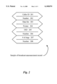
- FIG. 2 is a sample of a broadcast announcement record in an embodiment of the present invention.
- FIG. 4 is a system diagram of a call-routing system implemented in client-server mode in an embodiment of the present invention.
- FIG. 1 is a system diagram of a call-routing system according to a preferred embodiment of the present invention.
- Dotted lines 123 enclose elements of the system native to a customer's premises (CPE).
- This equipment in a preferred embodiment comprises a computerized telephony central switch 121 connected by a data link 212 to a processor 223 running an instance of a unique telephony server (T-Server) T-S 207.
- Switch 121 in conventional art distributes incoming calls (on line 105) to connected telephones, such as telephone 131 at a workstation 361 and telephone 132 at a second workstation 362.
- T-Server 207 running on processor 223 exerts controlling influence on routing of incoming calls, as is described in further detail below.
- each workstation (361, 362) has a PC with a video display, such as PC/VDU 331 at workstation 361 and PC/VDU 332 at workstation 362.
- a PC with a video display
- PC/VDU 331 at workstation 361
- PC/VDU 332 at workstation 362.
- PC/VDUs 331 and 332 in various embodiments are connected on a local area network (LAN) 301 which also connects to a data file server 303 and to processor 223 running an instance of T-Server 207.
- LAN local area network
- the arrangement of PC/VDU plus telephone at each workstation is a common arrangement for many company facilities, and has become more common as more and more people become computer literate.
- many companies are actively training employees in use of computers, and providing PC-type computer equipment, usually interconnected by company LAN, for employees to use.
- calls may originate at any remote call-in point, which is represented in FIG. 1 by region 100, referred to herein as the network cloud.
- Network cloud 100 may be a small regional portion of the world-wide network of connected telephony equipment, or may represent the entire world-wide network.
- An incoming call at any point in network cloud 100 is represented by vector 107 to service control point (SCP) 101 (typically a telephony central switch), which in this example is connected to an adjunct processor 103 and coupled thereby to an intelligent peripheral (I-P) 102, a distribution processor 104 and a processor 208 running a second instance of unique T-Server 207 as well as a statistical server (stat-server) 209.
- SCP service control point
- I-P intelligent peripheral
- processor 104 distribution processor
- processor 208 running a second instance of unique T-Server 207 as well as a statistical server (stat-server) 209.
- calls are forwarded to switch 121 at the customer premises equipment over telephone line 105, and associated data is forwarded in parallel to processor 223 over a digital network link 210.
- Such systems wherein data associated with a call is forwarded on a separate link from the call itself, are, to the inventor's knowledge at the time of the present patent application, not known in the art, but are known to the inventor. This feature, however, is not required in practice of the present invention, but preferred in some embodiments.
- DID direct inward dialing
- the phone call may also have caller ID attached (originating caller's phone number), and in those cases wherein a separate network digital data link is accomplished between processors at the origination end (208) and the customer's premises (223) cases a data packet associated with the call may be forwarded over link 210.
- T-S 207 which interacts continuously with switch 121 in this embodiment, is capable of transacting with data file server 303, given caller ID and/or other data associated with a call, to retrieve further information about the caller from data file server 303.
- incoming calls are not limited to two telephones as shown in FIG. 1.
- switch 121 There may be many more than two telephones connected to switch 121, other telephony equipment, such as facsimile equipment and data lines may also be connected and involved in routing decisions and transactions according to embodiments of the present invention.
- existing techniques such as virtual expansion for routing calls with a certain number to multiple destinations on some pre-programmed protocol may also be involved.
- the simple diagram of a switch with two telephones connected is meant to be illustrative for description of embodiments of the present invention.
- processor 223 in FIG. 1 is not strictly required in embodiments of the invention, depending on the level of machine intelligence and sophistication of switch 121. Switches for customer premises continue to be developed with new levels of intelligent capability, and some may be capable of interacting with other elements of the present invention without a separate processor between the switch and a LAN such as LAN 301. Processor 223 will be required to practice various embodiments of the invention with many existing telephony switches which may be used as element 121. In virtually all cases in practicing the present invention, an instance of unique T-Server 207 executing on a computerized platform will be required.
- routing intelligence is no longer confined to a central location such as telephony switch 121 or T-Server 207 running on a connected processor, but distributed in a manner that individual users of the system may customize routing at their own workstations, using individual PCs.
- This is accomplished in large part by control code executable at a user's computer workstation. It is not required that the actual code be always at the user's workstation, as it may be shared code resident at, for example a file server on LAN 301, such as file server 303.
- the unique code may be accessed from such a server and executed at any one of several workstations such as workstations 361 and 362 by PC/VDU 331 and PC/VDU 332 respectively. The location of stored code, and access to such code is not, however germane to the invention.
- an individual PC executes unique code to provide call-routing control for an individual.
- T-Server 207 is adapted to cooperate with code executed at individual PCs to route incoming calls.
- this unique routing process there are at least two different mechanisms that may be used.
- all calls are routed to a single routing point, and each individual routing application registers with that routing point.
- a record of each call is broadcast on LAN 301, as will be described more fully below, and filtering occurs at each PC router.
- This second alternative is typically more expensive than the first, and there are currently rather severe limitations on how many automatic call distribution (ACD) queues or routing points may be allocated on a typical central switch.
- ACD automatic call distribution
- an overall record of the call, prior to routing, is broadcast on LAN 301.
- This overall record can take a number of different forms, of which the example in FIG. 2 is just one exemplary form.
- the overall record consists of four data portions.
- One data portion consists of elements 201 and 202.
- Data element 201 identifies this portion as the caller ID associated with the incoming call, and element 202 is the caller ID number.
- a second data portion consists of data elements 203 and 204.
- This portion is a data set which may be transmitted via link 210 to processor 223 in parallel with the incoming call, or may be composed partly of data retrieved from server 303, using other call data as a pointer.
- Element 203 identifies the data as a data set, and element 204 is the pointer.
- elements 205 and 206 constitute a direct inward dialing (DID) number, and elements 207 and 208 fix number of rings.
- DID direct inward dialing
- a central element in the present invention is that a user at an individual PC runs an instance of a personal router application, providing that user with instant and complete control over routing of calls meant for that user (or, in some cases, associated users).
- the user's PC, such as PC/VDU 331 is connected typically by LAN to a processor such as processor 223, in turn connected to the central switch, such as switch 121.
- an individual workstation such as PC/VDU 331 at workstation 361
- the user has access to the local application which is interactive with code executed at T-Server 207 at processor 223, to control and customize routing for incoming calls, depending on certain data elements in the broadcast announcement record (FIG. 2).
- the individual user may in some embodiments load to his/her VDU a unique user interface, an example of which is shown in FIG. 3.
- FIG. 3 illustrates a window presentable to a user at an individual workstation, compatible, for example, with Windows operating systems.
- This is an input and display interface for a personal router, a variation of which may be assigned to each of selected employees to provide these individuals with an ability in conjunction with the premises telephone equipment to customize and periodically adjust the routing of certain incoming calls.
- the interface is for company XYZ and limited to employee John Doe.
- John Doe may program in a relatively high-level language, routing preferences for certain incoming calls, according to data broadcast for such calls on LAN 301.
- routing preferences for certain incoming calls, according to data broadcast for such calls on LAN 301.
- each user has a dedicated routing point, an incoming call is directed to the individual's computer, and the broadcast is not necessary.
- John Doe has programmed his interface to pick up all calls having Caller ID matched with a list "list1" after n1 rings.
- List1 is resident in John Doe's database associated with his own Personal Router, and John Doe may call up this list and amend, delete, and expand it as he wishes.
- the number of rings n1 may be any convenient number to accomplish John's purpose.
- John Doe may program negative lists as well. Although not specifically recommended, a negative list could be used to hang up on all calls that have an ID associated with a company or individual that has been making harassing calls to an employee, or to shunt such calls to a special tracking program or the like.
- John Doe in this instance has also programmed his personal router to send all calls bearing his assigned DID number to the telephone at his desk after 0 rings, and to an answering machine after n2 rings. Associations with data sets may also be made, comparing such data sets to stored profiles and the like. At the bottom of the display in this example a status summary of calls may be provided. A user may choose to have this window resident on his computer screen as a pix-on-pix, or to hide it and call it as needed. Also, it will be apparent to those with skill in the art that it is not strictly required that each selected person having an associated routing interface assigned have a computer at his/her elbow. For those persons not, for one reason or another, inclined to program their own routing, the interface may be called up and done by another, with appropriate access security applied. A secretary or system administrator may perform such functions, using any workstation connected to company LAN 301.
- the user interface at the user's workstation can take any of a variety of forms, and have a variety of functionality. Typically, when the user logs on, his system will be configured to execute the unique application to run in the background, and to monitor for incoming calls at all times the user is present and active. It will be apparent to those with skill in the art that this can be done in a variety of ways.
- the interface may be a Graphic User Interface (GUI) wherein icons may be used to represent calls, callers, and other users, and the individual user at one workstation may select to display icons as desired.
- GUI Graphic User Interface
- an incoming call may appear on a user's PC VDU as a small telephone in an announcement bar.
- announcement bars are familiar to those with skill in the art, such as seen on Operating System Desktops, where an e-mail arrival may be indicated by a letter icon and a sound.
- the user may activate a text balloon announcing the caller ID or other call data, or such data may be displayed directly in the icon.
- the system can be configured in such an embodiment to allow the user to route the call to his own phone with a click, to hang up with a double click, to drag the call to a holding queue (represented by a basket, for example,) to send the call to an answering machine, which may be done by dragging and dropping the telephone icon to an answering machine icon, to transfer the call to another person by dragging and dropping the telephone icon to an icon representing another user (such as the instant user's secretary or supervisor for example).
- a holding queue represented by a basket, for example
- Actions taken at the personal router interface at an individual PC on LAN 301 in embodiments of the present invention are codified as instructions on the LAN to T-Server 207 (in most cases) running on a processor such as processor 223, connected to central switch 121. If an individual user at a workstation, for example, has received an indicator of a waiting call, and has dragged the ringing telephone to his secretary's desk icon in his interface, his personal router interacts with T-Server 207 to instruct switch 121 to reroute the call to the secretary's telephone. In a similar manner, most actions at a personal router become instructions to switch 121, and in general each user having access to such a personal router can program responses to calls and respond to incoming calls in real time with a broad set of available responses.
- not necessarily all calls are routed by personal routers executed on PCs on LAN 301.
- Rules in switch 121 may also determine the fate of calls that are not eventually routed by personal routers. For example, all calls alive after seven rings may be switched to a recorded announcement, and the like. In this manner a very broad freedom of routing may be accomplished, with security and flexibility to adapt for changes in the organization.
- a Personal Desktop Router is implemented in a Client-Server architecture.
- This embodiment is illustrated with the aid of FIG. 4.
- a router 401 is provided and executes on processor 223 which also executes an instance of T-Server 207.
- Router 401 in this instance is a central router having routing rules divided in sections dedicated to each assigned user or DN on LAN 301.
- Unique Client Interface Packages represented by elements 401a and 401b are provided at individual workstations such as workstation 361 and workstation 362 connected to LAN 301.
- Client Interface Packages 401a and 401b are for the purpose of allowing users at the workstations to edit their own personal routing rules, much as has been described above for personal routers according to embodiments of the present invention, wherein the routers execute at the workstations.
- Client Packages 410a and 410b may be implemented as a Graphical User Interface (GUI) with iconic drag and drop features as described above with reference to FIG. 1, or may be of another suitable type designed to allow interaction with router 401.
- GUI Graphical User Interface
- router 401 in this embodiment, is not required to reside in processor 223, but may reside in any other machine capable of executing the router and connected or coupled to LAN 301, such as switch 121.
- the router could be executed, for example, on a server on the Internet, and accessed by a WEB browser by a client connected to LAN 301.
- router function does not occur at individual workstations 361 and 362 in this particular embodiment, editing capabilities provided to the user via client packages 401a and 401b can remain essentially the same as described in previous embodiments taught herein.
- router 401 is configured to allow a group manager or system agent to perform higher level configurations to routing rules, such as type of calls available, call parameters, user function or location changes, etc., while individual users may, through their interfaces, configure routing rules for their own calls, within the boundaries set by the supervisor.
- routing rules such as type of calls available, call parameters, user function or location changes, etc.
- a server-based router such as router 401 in this embodiment, wherein a unique client package is provided for editing purposes at a user's workstation, such as workstation 361, is heretofore unknown to the inventor.
- communication over analog lines 105 and data link 210, and other functions of the system, is essentially the same in method as is illustrated in FIG. 1 and described above with reference to FIG. 1.
- network cloud 100 and the components therein are essentially the same as in the embodiment in FIG. 1. For this reason much detail as to the dynamics of and paths of communication in an embodiment of the present invention with respect to FIG. 4 are not repeated here.
Abstract
Description
Claims (13)
Priority Applications (24)
| Application Number | Priority Date | Filing Date | Title |
|---|---|---|---|
| US08/869,815 US6148074A (en) | 1997-02-10 | 1997-06-04 | Personal desktop router |
| US08/928,861 US7031442B1 (en) | 1997-02-10 | 1997-09-12 | Methods and apparatus for personal routing in computer-simulated telephony |
| US08/949,586 US6198739B1 (en) | 1997-02-10 | 1997-10-14 | Voice extensions in a call-in center employing virtual restructuring for computer telephony integrated functionality |
| US08/950,253 US6359981B1 (en) | 1997-02-10 | 1997-10-14 | Virtualized computer telephony integrated link for enhanced functionality in call centers |
| US08/949,566 US6480600B1 (en) | 1997-02-10 | 1997-10-14 | Call and data correspondence in a call-in center employing virtual restructuring for computer telephony integrated functionality |
| US08/968,825 US6005931A (en) | 1997-02-10 | 1997-11-14 | Negotiated routing in telephony systems |
| EP98926248A EP0986875B1 (en) | 1997-06-04 | 1998-06-03 | A personal desktop router |
| JP50282799A JP2001526871A (en) | 1997-06-04 | 1998-06-03 | Personal desktop router |
| DE69834184T DE69834184T2 (en) | 1997-06-04 | 1998-06-03 | PERSONAL DESKTOP PATH |
| PCT/US1998/011442 WO1998056141A1 (en) | 1997-06-04 | 1998-06-03 | A personal desktop router |
| CA002289198A CA2289198C (en) | 1997-06-04 | 1998-06-03 | A personal desktop router |
| US09/443,057 US6122360A (en) | 1997-02-10 | 1999-11-18 | Negotiated routing in telephony systems |
| US09/478,126 US6434231B2 (en) | 1997-02-10 | 2000-01-05 | Virtualized computer telephony integrated link for enhanced functionality in call centers |
| US09/661,181 US7020264B1 (en) | 1997-02-10 | 2000-09-13 | Negotiated routing in telephony systems |
| US10/234,691 US6735298B2 (en) | 1997-02-10 | 2002-09-03 | Call and data correspondence in a call-in center employing virtual restructuring for computer telephony integrated functionality |
| US10/843,802 US7903807B2 (en) | 1997-02-10 | 2004-05-11 | Call and data correspondence in a call-in center employing virtual restructuring for computer telephony integrated functionality |
| US11/317,946 US20060133594A1 (en) | 1997-02-10 | 2005-12-22 | Call center apparatus and functionality in telephony |
| US11/388,089 US7231032B2 (en) | 1997-02-10 | 2006-03-22 | Negotiated routing in telephony systems |
| JP2006127262A JP2006295947A (en) | 1997-06-04 | 2006-05-01 | Personal desktop router |
| US11/926,542 US8358769B2 (en) | 1997-02-10 | 2007-10-29 | Personal desktop router |
| US13/671,558 US20130129067A1 (en) | 1997-02-10 | 2012-11-08 | Personal desktop router |
| US13/789,640 USRE45606E1 (en) | 1997-02-10 | 2013-03-07 | Call and data correspondence in a call-in center employing virtual restructuring for computer telephony integrated functionality |
| US13/861,367 US20130230160A1 (en) | 1997-02-10 | 2013-04-11 | Call and data correspondence in a call-in center employing virtual restructuring for computer telephony integrated functionality |
| US14/708,122 US9516171B2 (en) | 1997-02-10 | 2015-05-08 | Personal desktop router |
Applications Claiming Priority (3)
| Application Number | Priority Date | Filing Date | Title |
|---|---|---|---|
| US08/797,420 US6185291B1 (en) | 1997-02-10 | 1997-02-10 | Personal desktop router |
| US08/802,667 US6201863B1 (en) | 1997-02-10 | 1997-02-19 | Personal desktop router |
| US08/869,815 US6148074A (en) | 1997-02-10 | 1997-06-04 | Personal desktop router |
Related Parent Applications (3)
| Application Number | Title | Priority Date | Filing Date |
|---|---|---|---|
| US08/802,667 Continuation-In-Part US6201863B1 (en) | 1997-02-10 | 1997-02-19 | Personal desktop router |
| US08/833,340 Continuation-In-Part US6560328B1 (en) | 1997-02-10 | 1997-04-03 | Voice extensions in a call-in center employing virtual restructuring for computer telephony integrated functionality |
| US08802667 Continuation-In-Part | 1999-02-19 |
Related Child Applications (4)
| Application Number | Title | Priority Date | Filing Date |
|---|---|---|---|
| US08/928,861 Continuation-In-Part US7031442B1 (en) | 1997-02-10 | 1997-09-12 | Methods and apparatus for personal routing in computer-simulated telephony |
| US08/968,825 Continuation-In-Part US6005931A (en) | 1997-02-10 | 1997-11-14 | Negotiated routing in telephony systems |
| US08928861 Continuation-In-Part | 1999-09-12 | ||
| US09/443,057 Continuation-In-Part US6122360A (en) | 1997-02-10 | 1999-11-18 | Negotiated routing in telephony systems |
Publications (1)
| Publication Number | Publication Date |
|---|---|
| US6148074A true US6148074A (en) | 2000-11-14 |
Family
ID=25354313
Family Applications (1)
| Application Number | Title | Priority Date | Filing Date |
|---|---|---|---|
| US08/869,815 Expired - Lifetime US6148074A (en) | 1997-02-10 | 1997-06-04 | Personal desktop router |
Country Status (6)
| Country | Link |
|---|---|
| US (1) | US6148074A (en) |
| EP (1) | EP0986875B1 (en) |
| JP (2) | JP2001526871A (en) |
| CA (1) | CA2289198C (en) |
| DE (1) | DE69834184T2 (en) |
| WO (1) | WO1998056141A1 (en) |
Cited By (41)
| Publication number | Priority date | Publication date | Assignee | Title |
|---|---|---|---|---|
| US20020024954A1 (en) * | 2000-08-08 | 2002-02-28 | Sbc Technology Resources, Inc. | Controller based call control for ATM SVC signaling |
| US6421325B1 (en) * | 1998-04-28 | 2002-07-16 | Genesys Telecomm Lab Inc | Methods and apparatus for enhancing wireless data network telephony including a personal router in a client |
| US6466663B1 (en) | 1997-09-30 | 2002-10-15 | Don Ravenscroft | Monitoring system client for a call center |
| US6490350B2 (en) | 1997-09-30 | 2002-12-03 | Mci Communications Corporation | Monitoring system for telephony resources in a call center |
| US6658106B1 (en) * | 1997-09-19 | 2003-12-02 | Wesley Atkinson | Desktop telephony application program for a call center agent |
| US20040085968A1 (en) * | 2002-11-04 | 2004-05-06 | Sbc Properties, L.P. | Peer to peer SVC-based DSL service |
| US20040085969A1 (en) * | 2002-11-04 | 2004-05-06 | Sbc Properties, L.P. | Client server SVC-based DSL service |
| US6735298B2 (en) | 1997-02-10 | 2004-05-11 | Genesys Telecommunications Laboratoiries, Inc. | Call and data correspondence in a call-in center employing virtual restructuring for computer telephony integrated functionality |
| US6760444B1 (en) * | 1999-01-08 | 2004-07-06 | Cisco Technology, Inc. | Mobile IP authentication |
| US20040165592A1 (en) * | 2003-02-21 | 2004-08-26 | Sbc Properties, L.P. | Extended virtual user-to-network interface with ATM network |
| US20050025091A1 (en) * | 2002-11-22 | 2005-02-03 | Cisco Technology, Inc. | Methods and apparatus for dynamic session key generation and rekeying in mobile IP |
| US6912272B2 (en) | 2001-09-21 | 2005-06-28 | Talkflow Systems, Llc | Method and apparatus for managing communications and for creating communication routing rules |
| US20060104247A1 (en) * | 2004-11-17 | 2006-05-18 | Cisco Technology, Inc. | Infrastructure-less bootstrapping: trustless bootstrapping to enable mobility for mobile devices |
| US7050423B2 (en) | 2000-08-07 | 2006-05-23 | Sbc Technology Resources, Inc. | Multiservice use of network connection capability |
| US20060210047A1 (en) * | 1997-02-10 | 2006-09-21 | Igor Neyman | Negotiated routing in telephony systems |
| US7136386B2 (en) | 2001-07-19 | 2006-11-14 | Sbc Technology Resources, Inc. | Virtual private network over asynchronous transfer mode |
| US7149229B1 (en) | 1999-01-08 | 2006-12-12 | Cisco Technology, Inc. | Mobile IP accounting |
| US7187678B2 (en) | 2001-08-13 | 2007-03-06 | At&T Labs, Inc. | Authentication for use of high speed network resources |
| US20070056023A1 (en) * | 1999-01-08 | 2007-03-08 | Cisco Technology, Inc., A Corporation Of California | Mobile IP authentication |
| US20070091843A1 (en) * | 2005-10-25 | 2007-04-26 | Cisco Technology, Inc. | EAP/SIM authentication for Mobile IP to leverage GSM/SIM authentication infrastructure |
| US20080075261A1 (en) * | 2006-08-31 | 2008-03-27 | Microsoft Corporation | Client controlled dynamic call forwarding |
| US7639802B2 (en) | 2004-09-27 | 2009-12-29 | Cisco Technology, Inc. | Methods and apparatus for bootstrapping Mobile-Foreign and Foreign-Home authentication keys in Mobile IP |
| US7870389B1 (en) | 2002-12-24 | 2011-01-11 | Cisco Technology, Inc. | Methods and apparatus for authenticating mobility entities using kerberos |
| US20110026702A1 (en) * | 2008-04-04 | 2011-02-03 | Johannes Jan Bot | Managing communications |
| EP2448230A1 (en) | 2010-11-01 | 2012-05-02 | Mitel Networks Corporation | Call screening procedure comprising a call authorization feature |
| US20120157068A1 (en) * | 2010-12-17 | 2012-06-21 | Verizon Patent And Licensing Inc. | Fixed mobile convergence and voice call continuity using a mobile device/docking station |
| US8879420B2 (en) | 2010-12-17 | 2014-11-04 | Verizon Patent And Licensing Inc. | Mobile phone docking station VPNs |
| US8971216B2 (en) | 1998-09-11 | 2015-03-03 | Alcatel Lucent | Method for routing transactions between internal and external partners in a communication center |
| US9002920B2 (en) | 1998-09-11 | 2015-04-07 | Genesys Telecommunications Laboratories, Inc. | Method and apparatus for extended management of state and interaction of a remote knowledge worker from a contact center |
| US9008039B2 (en) | 2010-12-17 | 2015-04-14 | Verizon Patent And Licensing Inc. | Mobile phone/docking station call continuity |
| US9008075B2 (en) | 2005-12-22 | 2015-04-14 | Genesys Telecommunications Laboratories, Inc. | System and methods for improving interaction routing performance |
| US9060075B2 (en) | 2010-12-17 | 2015-06-16 | Verizon Patent And Licensing Inc. | Mobile phone/docking station emergency call routing |
| USRE45583E1 (en) | 1999-12-01 | 2015-06-23 | Genesys Telecommunications Laboratories, Inc. | Method and apparatus for providing enhanced communication capability for mobile devices on a virtual private network |
| USRE45597E1 (en) | 1998-04-28 | 2015-06-30 | Genesys Telecommunications Laboratories, Inc. | Methods and apparatus for enhancing wireless data network telephony, including quality of service monitoring and control |
| US9143359B2 (en) | 2010-12-17 | 2015-09-22 | Verizon Patent And Licensing Inc. | Mobile phone docking station for VoIP |
| USRE46060E1 (en) | 1997-02-10 | 2016-07-05 | Genesys Telecommunications Laboratories, Inc. | In-band signaling for routing |
| USRE46153E1 (en) | 1998-09-11 | 2016-09-20 | Genesys Telecommunications Laboratories, Inc. | Method and apparatus enabling voice-based management of state and interaction of a remote knowledge worker in a contact center environment |
| US9553755B2 (en) | 1998-02-17 | 2017-01-24 | Genesys Telecommunications Laboratories, Inc. | Method for implementing and executing communication center routing strategies represented in extensible markup language |
| USRE46438E1 (en) | 1999-09-24 | 2017-06-13 | Genesys Telecommunications Laboratories, Inc. | Method and apparatus for data-linking a mobile knowledge worker to home communication-center infrastructure |
| US9736665B2 (en) | 2010-12-17 | 2017-08-15 | Verizon Patent And Licensing Inc. | Original calling identification with mobile phone in docked mode |
| USRE46528E1 (en) | 1997-11-14 | 2017-08-29 | Genesys Telecommunications Laboratories, Inc. | Implementation of call-center outbound dialing capability at a telephony network level |
Families Citing this family (8)
| Publication number | Priority date | Publication date | Assignee | Title |
|---|---|---|---|---|
| US7031442B1 (en) | 1997-02-10 | 2006-04-18 | Genesys Telecommunications Laboratories, Inc. | Methods and apparatus for personal routing in computer-simulated telephony |
| JP4497580B2 (en) * | 1999-04-30 | 2010-07-07 | キヤノン株式会社 | Data processing apparatus, data processing method, and storage medium storing computer-readable program |
| KR100562140B1 (en) * | 1999-11-02 | 2006-03-21 | 주식회사 케이티 | Method for transmitting signal through channel conversion |
| KR100354807B1 (en) * | 2000-05-16 | 2002-10-05 | 주식회사 한국밴통신 | A telegate, a computer telephony integration system based on the telegate and methods for processing incoming call and outgoing call by using the telegate |
| FI4638U1 (en) * | 2000-05-26 | 2000-09-29 | Fulcrum Lab Ag | Communications Network |
| GB2425913B (en) | 2005-05-04 | 2009-07-08 | Arona Ltd | Call handling |
| US7920692B2 (en) | 2005-10-03 | 2011-04-05 | Verizon Data Services Llc | PBX call management |
| EP2043345A1 (en) * | 2007-09-26 | 2009-04-01 | Alcatel Lucent | Method of supporting a routing of communcations |
Citations (6)
| Publication number | Priority date | Publication date | Assignee | Title |
|---|---|---|---|---|
| US5583922A (en) * | 1990-09-27 | 1996-12-10 | Radish Communication Systems, Inc. | Telecommunication system for automatic switching between voice and visual data communications using forms |
| US5621789A (en) * | 1993-09-01 | 1997-04-15 | Teknekron Infoswitch Corporation | Method and system for integrating a plurality of call center agent performance enhancement modules |
| US5630127A (en) * | 1992-05-15 | 1997-05-13 | International Business Machines Corporation | Program storage device and computer program product for managing an event driven management information system with rule-based application structure stored in a relational database |
| US5768360A (en) * | 1992-03-09 | 1998-06-16 | Advantis | Subscriber call routing processing system |
| US5850433A (en) * | 1996-05-01 | 1998-12-15 | Sprint Communication Co. L.P. | System and method for providing an on-line directory service |
| US5974414A (en) * | 1996-07-03 | 1999-10-26 | Open Port Technology, Inc. | System and method for automated received message handling and distribution |
Family Cites Families (10)
| Publication number | Priority date | Publication date | Assignee | Title |
|---|---|---|---|---|
| US4771425A (en) * | 1984-10-29 | 1988-09-13 | Stratacom, Inc. | Synchoronous packet voice/data communication system |
| JPH04336742A (en) * | 1991-05-14 | 1992-11-24 | Fujitsu Ltd | Exchange service control system |
| GB2273225B (en) * | 1992-11-11 | 1996-07-17 | Rockwell International Corp | Control device for telephone network switching |
| US5414762A (en) * | 1994-01-18 | 1995-05-09 | Q.Sys International, Inc. | Telephony controller with functionality command converter |
| US5526353A (en) * | 1994-12-20 | 1996-06-11 | Henley; Arthur | System and method for communication of audio data over a packet-based network |
| CA2139081C (en) * | 1994-12-23 | 1999-02-02 | Alastair Gordon | Unified messaging system and method |
| JP3591052B2 (en) * | 1995-06-06 | 2004-11-17 | 松下電器産業株式会社 | Private telephone system and information processing method thereof |
| US5619557A (en) * | 1995-07-10 | 1997-04-08 | Rockwell International Corporation | Telephone switching system and method for controlling incoming telephone calls to remote agents and for collecting and providing call data |
| CA2161506C (en) * | 1995-10-26 | 2000-01-25 | Deborah Pinard | File retrieval with incoming calls |
| US6201863B1 (en) * | 1997-02-10 | 2001-03-13 | Genesys Telecommunications Laboratories, Inc. | Personal desktop router |
-
1997
- 1997-06-04 US US08/869,815 patent/US6148074A/en not_active Expired - Lifetime
-
1998
- 1998-06-03 DE DE69834184T patent/DE69834184T2/en not_active Expired - Lifetime
- 1998-06-03 CA CA002289198A patent/CA2289198C/en not_active Expired - Fee Related
- 1998-06-03 EP EP98926248A patent/EP0986875B1/en not_active Expired - Lifetime
- 1998-06-03 JP JP50282799A patent/JP2001526871A/en not_active Withdrawn
- 1998-06-03 WO PCT/US1998/011442 patent/WO1998056141A1/en active IP Right Grant
-
2006
- 2006-05-01 JP JP2006127262A patent/JP2006295947A/en active Pending
Patent Citations (6)
| Publication number | Priority date | Publication date | Assignee | Title |
|---|---|---|---|---|
| US5583922A (en) * | 1990-09-27 | 1996-12-10 | Radish Communication Systems, Inc. | Telecommunication system for automatic switching between voice and visual data communications using forms |
| US5768360A (en) * | 1992-03-09 | 1998-06-16 | Advantis | Subscriber call routing processing system |
| US5630127A (en) * | 1992-05-15 | 1997-05-13 | International Business Machines Corporation | Program storage device and computer program product for managing an event driven management information system with rule-based application structure stored in a relational database |
| US5621789A (en) * | 1993-09-01 | 1997-04-15 | Teknekron Infoswitch Corporation | Method and system for integrating a plurality of call center agent performance enhancement modules |
| US5850433A (en) * | 1996-05-01 | 1998-12-15 | Sprint Communication Co. L.P. | System and method for providing an on-line directory service |
| US5974414A (en) * | 1996-07-03 | 1999-10-26 | Open Port Technology, Inc. | System and method for automated received message handling and distribution |
Cited By (94)
| Publication number | Priority date | Publication date | Assignee | Title |
|---|---|---|---|---|
| USRE46060E1 (en) | 1997-02-10 | 2016-07-05 | Genesys Telecommunications Laboratories, Inc. | In-band signaling for routing |
| USRE46243E1 (en) | 1997-02-10 | 2016-12-20 | Genesys Telecommunications Laboratories, Inc. | In-band signaling for routing |
| US20040208134A1 (en) * | 1997-02-10 | 2004-10-21 | Igor Neyman | Call and data correspondence in a call-in center employing virtual restructuring for computer telephony integrated functionality |
| US20060210047A1 (en) * | 1997-02-10 | 2006-09-21 | Igor Neyman | Negotiated routing in telephony systems |
| US7231032B2 (en) | 1997-02-10 | 2007-06-12 | Genesys Telecommunications Laboratories, Inc. | Negotiated routing in telephony systems |
| USRE45606E1 (en) | 1997-02-10 | 2015-07-07 | Genesys Telecommunications Laboratories, Inc. | Call and data correspondence in a call-in center employing virtual restructuring for computer telephony integrated functionality |
| US7903807B2 (en) | 1997-02-10 | 2011-03-08 | Genesys Telecommunications Laboratories, Inc. | Call and data correspondence in a call-in center employing virtual restructuring for computer telephony integrated functionality |
| US6735298B2 (en) | 1997-02-10 | 2004-05-11 | Genesys Telecommunications Laboratoiries, Inc. | Call and data correspondence in a call-in center employing virtual restructuring for computer telephony integrated functionality |
| US6658106B1 (en) * | 1997-09-19 | 2003-12-02 | Wesley Atkinson | Desktop telephony application program for a call center agent |
| US6782087B1 (en) | 1997-09-19 | 2004-08-24 | Mci Communications Corporation | Desktop telephony application program for a call center agent |
| USRE46521E1 (en) | 1997-09-30 | 2017-08-22 | Genesys Telecommunications Laboratories, Inc. | Method and apparatus for extended management of state and interaction of a remote knowledge worker from a contact center |
| US6466663B1 (en) | 1997-09-30 | 2002-10-15 | Don Ravenscroft | Monitoring system client for a call center |
| US6490350B2 (en) | 1997-09-30 | 2002-12-03 | Mci Communications Corporation | Monitoring system for telephony resources in a call center |
| USRE46528E1 (en) | 1997-11-14 | 2017-08-29 | Genesys Telecommunications Laboratories, Inc. | Implementation of call-center outbound dialing capability at a telephony network level |
| US9553755B2 (en) | 1998-02-17 | 2017-01-24 | Genesys Telecommunications Laboratories, Inc. | Method for implementing and executing communication center routing strategies represented in extensible markup language |
| USRE45597E1 (en) | 1998-04-28 | 2015-06-30 | Genesys Telecommunications Laboratories, Inc. | Methods and apparatus for enhancing wireless data network telephony, including quality of service monitoring and control |
| USRE45149E1 (en) | 1998-04-28 | 2014-09-23 | Genesys Telecommunications Laboratories, Inc. | Methods and apparatus for enhancing wireless data network telephony, including quality of service monitoring and control |
| US6421325B1 (en) * | 1998-04-28 | 2002-07-16 | Genesys Telecomm Lab Inc | Methods and apparatus for enhancing wireless data network telephony including a personal router in a client |
| US9002920B2 (en) | 1998-09-11 | 2015-04-07 | Genesys Telecommunications Laboratories, Inc. | Method and apparatus for extended management of state and interaction of a remote knowledge worker from a contact center |
| US8971216B2 (en) | 1998-09-11 | 2015-03-03 | Alcatel Lucent | Method for routing transactions between internal and external partners in a communication center |
| USRE46153E1 (en) | 1998-09-11 | 2016-09-20 | Genesys Telecommunications Laboratories, Inc. | Method and apparatus enabling voice-based management of state and interaction of a remote knowledge worker in a contact center environment |
| US9350808B2 (en) | 1998-09-11 | 2016-05-24 | Alcatel Lucent | Method for routing transactions between internal and external partners in a communication center |
| US10218848B2 (en) | 1998-09-11 | 2019-02-26 | Genesys Telecommunications Laboratories, Inc. | Method and apparatus for extended management of state and interaction of a remote knowledge worker from a contact center |
| USRE46387E1 (en) | 1998-09-11 | 2017-05-02 | Genesys Telecommunications Laboratories, Inc. | Method and apparatus for extended management of state and interaction of a remote knowledge worker from a contact center |
| US20040234075A1 (en) * | 1999-01-08 | 2004-11-25 | Cisco Technology, Inc., A Corporation Of California | Mobile IP authentication |
| US7421077B2 (en) | 1999-01-08 | 2008-09-02 | Cisco Technology, Inc. | Mobile IP authentication |
| US20070058673A1 (en) * | 1999-01-08 | 2007-03-15 | Cisco Technology, Inc. | Mobile IP accounting |
| US6760444B1 (en) * | 1999-01-08 | 2004-07-06 | Cisco Technology, Inc. | Mobile IP authentication |
| US7817664B2 (en) | 1999-01-08 | 2010-10-19 | Cisco Technology, Inc. | Mobile IP accounting |
| US7168090B2 (en) | 1999-01-08 | 2007-01-23 | Cisco Technology, Inc. | Mobile IP authentication |
| US20070056023A1 (en) * | 1999-01-08 | 2007-03-08 | Cisco Technology, Inc., A Corporation Of California | Mobile IP authentication |
| US7149229B1 (en) | 1999-01-08 | 2006-12-12 | Cisco Technology, Inc. | Mobile IP accounting |
| USRE46438E1 (en) | 1999-09-24 | 2017-06-13 | Genesys Telecommunications Laboratories, Inc. | Method and apparatus for data-linking a mobile knowledge worker to home communication-center infrastructure |
| USRE46457E1 (en) | 1999-09-24 | 2017-06-27 | Genesys Telecommunications Laboratories, Inc. | Method and apparatus for data-linking a mobile knowledge worker to home communication-center infrastructure |
| USRE45583E1 (en) | 1999-12-01 | 2015-06-23 | Genesys Telecommunications Laboratories, Inc. | Method and apparatus for providing enhanced communication capability for mobile devices on a virtual private network |
| US20060239268A1 (en) * | 2000-08-07 | 2006-10-26 | Sbc Technology Resources, Inc. | Multiservice use of network connection capability under user-to-network interface signaling |
| US7889717B2 (en) | 2000-08-07 | 2011-02-15 | At&T Labs, Inc. | Multiservice use of network connection capability |
| US7050423B2 (en) | 2000-08-07 | 2006-05-23 | Sbc Technology Resources, Inc. | Multiservice use of network connection capability |
| US7088720B1 (en) | 2000-08-07 | 2006-08-08 | Sbc Technology Resources, Inc. | Multiservice use of network connection capability under user-to-network interface signaling |
| US20060114889A1 (en) * | 2000-08-07 | 2006-06-01 | Sbc Technology Resources, Inc. | Multiservice use of network connection capability |
| US7561577B2 (en) | 2000-08-07 | 2009-07-14 | At & T Labs, Inc. | Multiservice use of network connection capability under user-to-network interface signaling |
| US20080089345A1 (en) * | 2000-08-08 | 2008-04-17 | At&T Labs, Inc. | Controller based call control for atm svc signaling |
| US7307993B2 (en) | 2000-08-08 | 2007-12-11 | At&T Labs, Inc. | Controller based call control for ATM SVC signaling |
| US20020024954A1 (en) * | 2000-08-08 | 2002-02-28 | Sbc Technology Resources, Inc. | Controller based call control for ATM SVC signaling |
| US7609699B2 (en) | 2001-07-19 | 2009-10-27 | At&T Labs, Inc. | Virtual private network over asynchronous transfer mode |
| US7136386B2 (en) | 2001-07-19 | 2006-11-14 | Sbc Technology Resources, Inc. | Virtual private network over asynchronous transfer mode |
| US20070086466A1 (en) * | 2001-07-19 | 2007-04-19 | Sbc Technology Resources, Inc. | Virtual private network over asynchronous transfer mode |
| US7187678B2 (en) | 2001-08-13 | 2007-03-06 | At&T Labs, Inc. | Authentication for use of high speed network resources |
| US7701947B2 (en) | 2001-08-13 | 2010-04-20 | At&T Labs, Inc. | Authentication for use of high speed network resources |
| US20070121643A1 (en) * | 2001-08-13 | 2007-05-31 | At&T Labs, Inc. | Authentication for use of high speed network resources |
| US6912272B2 (en) | 2001-09-21 | 2005-06-28 | Talkflow Systems, Llc | Method and apparatus for managing communications and for creating communication routing rules |
| USRE46538E1 (en) | 2002-10-10 | 2017-09-05 | Genesys Telecommunications Laboratories, Inc. | Method and apparatus for extended management of state and interaction of a remote knowledge worker from a contact center |
| US20090327500A1 (en) * | 2002-11-04 | 2009-12-31 | At&T Intellectual Property I, L.P. | Peer to peer svc-based dsl service |
| US20040085968A1 (en) * | 2002-11-04 | 2004-05-06 | Sbc Properties, L.P. | Peer to peer SVC-based DSL service |
| US20040085969A1 (en) * | 2002-11-04 | 2004-05-06 | Sbc Properties, L.P. | Client server SVC-based DSL service |
| US8199760B2 (en) | 2002-11-04 | 2012-06-12 | At&T Intellectual Property I, L.P. | Peer to peer SVC-based DSL service |
| US7602788B2 (en) | 2002-11-04 | 2009-10-13 | At&T Intellectual Property I, L.P. | Peer to peer SVC-based DSL service |
| US7701953B2 (en) | 2002-11-04 | 2010-04-20 | At&T Intellectual Property I, L.P. | Client server SVC-based DSL service |
| US20050025091A1 (en) * | 2002-11-22 | 2005-02-03 | Cisco Technology, Inc. | Methods and apparatus for dynamic session key generation and rekeying in mobile IP |
| US7475241B2 (en) | 2002-11-22 | 2009-01-06 | Cisco Technology, Inc. | Methods and apparatus for dynamic session key generation and rekeying in mobile IP |
| US7870389B1 (en) | 2002-12-24 | 2011-01-11 | Cisco Technology, Inc. | Methods and apparatus for authenticating mobility entities using kerberos |
| US7839866B2 (en) | 2003-02-21 | 2010-11-23 | At&T Intellectual Property I, L.P. | Extended virtual user-to-network interface with ATM network |
| US20040165592A1 (en) * | 2003-02-21 | 2004-08-26 | Sbc Properties, L.P. | Extended virtual user-to-network interface with ATM network |
| US7382785B2 (en) | 2003-02-21 | 2008-06-03 | At&T Knowledge Ventures, L.P. | Extended virtual user-to-network interface with ATM network |
| US20080175250A1 (en) * | 2003-02-21 | 2008-07-24 | At&T Knowledge Ventures, L.P. | Extended virtual user-to-network interface with atm network |
| US7639802B2 (en) | 2004-09-27 | 2009-12-29 | Cisco Technology, Inc. | Methods and apparatus for bootstrapping Mobile-Foreign and Foreign-Home authentication keys in Mobile IP |
| US20100166179A1 (en) * | 2004-09-27 | 2010-07-01 | Cisco Technology, Inc. | Methods and apparatus for bootstrapping mobile-foreign and foreign-home authentication keys in mobile ip |
| US8165290B2 (en) | 2004-09-27 | 2012-04-24 | Cisco Technology, Inc. | Methods and apparatus for bootstrapping mobile-foreign and foreign-home authentication keys in mobile IP |
| US20060104247A1 (en) * | 2004-11-17 | 2006-05-18 | Cisco Technology, Inc. | Infrastructure-less bootstrapping: trustless bootstrapping to enable mobility for mobile devices |
| US7502331B2 (en) | 2004-11-17 | 2009-03-10 | Cisco Technology, Inc. | Infrastructure-less bootstrapping: trustless bootstrapping to enable mobility for mobile devices |
| US20090144809A1 (en) * | 2004-11-17 | 2009-06-04 | Cisco Technology, Inc. | Infrastructure-less bootstrapping: trustless bootstrapping to enable mobility for mobile devices |
| US8584207B2 (en) | 2004-11-17 | 2013-11-12 | Cisco Technology, Inc. | Infrastructure-less bootstrapping: trustless bootstrapping to enable mobility for mobile devices |
| US7626963B2 (en) | 2005-10-25 | 2009-12-01 | Cisco Technology, Inc. | EAP/SIM authentication for mobile IP to leverage GSM/SIM authentication infrastructure |
| US20070091843A1 (en) * | 2005-10-25 | 2007-04-26 | Cisco Technology, Inc. | EAP/SIM authentication for Mobile IP to leverage GSM/SIM authentication infrastructure |
| US9854006B2 (en) | 2005-12-22 | 2017-12-26 | Genesys Telecommunications Laboratories, Inc. | System and methods for improving interaction routing performance |
| US9008075B2 (en) | 2005-12-22 | 2015-04-14 | Genesys Telecommunications Laboratories, Inc. | System and methods for improving interaction routing performance |
| AU2007313049C1 (en) * | 2006-08-31 | 2011-04-07 | Microsoft Technology Licensing, Llc | Client controlled dynamic call forwarding |
| RU2499359C2 (en) * | 2006-08-31 | 2013-11-20 | Майкрософт Корпорейшн | Client controlled dynamic call forwarding |
| US20080075261A1 (en) * | 2006-08-31 | 2008-03-27 | Microsoft Corporation | Client controlled dynamic call forwarding |
| AU2007313049B2 (en) * | 2006-08-31 | 2010-12-09 | Microsoft Technology Licensing, Llc | Client controlled dynamic call forwarding |
| US8837704B2 (en) * | 2006-08-31 | 2014-09-16 | Microsoft Corporation | Client controlled dynamic call forwarding |
| US20110026702A1 (en) * | 2008-04-04 | 2011-02-03 | Johannes Jan Bot | Managing communications |
| CN101981906A (en) * | 2008-04-04 | 2011-02-23 | 艾利森电话股份有限公司 | Managing communications |
| EP2448230A1 (en) | 2010-11-01 | 2012-05-02 | Mitel Networks Corporation | Call screening procedure comprising a call authorization feature |
| US9237229B2 (en) | 2010-11-01 | 2016-01-12 | Mitel Networks Corporation | Call authorization feature |
| US20120157068A1 (en) * | 2010-12-17 | 2012-06-21 | Verizon Patent And Licensing Inc. | Fixed mobile convergence and voice call continuity using a mobile device/docking station |
| US9338093B2 (en) | 2010-12-17 | 2016-05-10 | Verizon Patent And Licensing Inc. | Mobile phone docking station VPNs |
| US9143359B2 (en) | 2010-12-17 | 2015-09-22 | Verizon Patent And Licensing Inc. | Mobile phone docking station for VoIP |
| US9736665B2 (en) | 2010-12-17 | 2017-08-15 | Verizon Patent And Licensing Inc. | Original calling identification with mobile phone in docked mode |
| US8879420B2 (en) | 2010-12-17 | 2014-11-04 | Verizon Patent And Licensing Inc. | Mobile phone docking station VPNs |
| US9060075B2 (en) | 2010-12-17 | 2015-06-16 | Verizon Patent And Licensing Inc. | Mobile phone/docking station emergency call routing |
| US9031059B2 (en) * | 2010-12-17 | 2015-05-12 | Verizon Patent And Licensing Inc. | Fixed mobile convergence and voice call continuity using a mobile device/docking station |
| US9826099B2 (en) | 2010-12-17 | 2017-11-21 | Verizon Patent And Licensing Inc. | Mobile phone/docking station call continuity |
| US9008039B2 (en) | 2010-12-17 | 2015-04-14 | Verizon Patent And Licensing Inc. | Mobile phone/docking station call continuity |
Also Published As
| Publication number | Publication date |
|---|---|
| DE69834184T2 (en) | 2007-03-08 |
| JP2001526871A (en) | 2001-12-18 |
| CA2289198C (en) | 2003-11-18 |
| EP0986875A1 (en) | 2000-03-22 |
| EP0986875B1 (en) | 2006-04-12 |
| EP0986875A4 (en) | 2002-09-04 |
| WO1998056141A1 (en) | 1998-12-10 |
| JP2006295947A (en) | 2006-10-26 |
| CA2289198A1 (en) | 1998-12-10 |
| DE69834184D1 (en) | 2006-05-24 |
Similar Documents
| Publication | Publication Date | Title |
|---|---|---|
| US6148074A (en) | Personal desktop router | |
| US7020264B1 (en) | Negotiated routing in telephony systems | |
| US6201863B1 (en) | Personal desktop router | |
| US6122360A (en) | Negotiated routing in telephony systems | |
| US9516171B2 (en) | Personal desktop router | |
| US6434231B2 (en) | Virtualized computer telephony integrated link for enhanced functionality in call centers | |
| USRE45606E1 (en) | Call and data correspondence in a call-in center employing virtual restructuring for computer telephony integrated functionality | |
| EP1031232B1 (en) | Negotiated routing in telephony systems | |
| US20130230160A1 (en) | Call and data correspondence in a call-in center employing virtual restructuring for computer telephony integrated functionality | |
| US6185291B1 (en) | Personal desktop router |
Legal Events
| Date | Code | Title | Description |
|---|---|---|---|
| AS | Assignment |
Owner name: GENESYS TELECOMMUNICATIONS LABORATORIES, INC., A C Free format text: ASSIGNMENT OF ASSIGNORS INTEREST;ASSIGNORS:MILOSLAVSKY, ALEC;NEYMAN, IGOR;REEL/FRAME:008956/0773 Effective date: 19971219 |
|
| STCF | Information on status: patent grant |
Free format text: PATENTED CASE |
|
| FEPP | Fee payment procedure |
Free format text: PAYOR NUMBER ASSIGNED (ORIGINAL EVENT CODE: ASPN); ENTITY STATUS OF PATENT OWNER: LARGE ENTITY |
|
| FPAY | Fee payment |
Year of fee payment: 4 |
|
| FPAY | Fee payment |
Year of fee payment: 8 |
|
| AS | Assignment |
Owner name: GOLDMAN SACHS LENDING PARTNERS LLC, NEW YORK Free format text: SECURITY AGREEMENT;ASSIGNOR:GENESYS TELECOMMUNICATIONS LABORATORIES, INC.;REEL/FRAME:027623/0096 Effective date: 20120131 |
|
| FPAY | Fee payment |
Year of fee payment: 12 |
|
| AS | Assignment |
Owner name: GENESYS TELECOMMUNICATIONS LABORATORIES, INC., CAL Free format text: RELEASE BY SECURED PARTY;ASSIGNOR:GOLDMAN SACHS LENDING PARTNERS LLC;REEL/FRAME:029778/0060 Effective date: 20130208 Owner name: GOLDMAN SACHS BANK USA, NEW YORK Free format text: SECURITY AGREEMENT;ASSIGNOR:GENESYS TELECOMMUNICATIONS LABORATORIES, INC.;REEL/FRAME:029778/0939 Effective date: 20130208 |
|
| AS | Assignment |
Owner name: JPMORGAN CHASE BANK, N.A., AS COLLATERAL AGENT, DE Free format text: SECURITY AGREEMENT;ASSIGNORS:GENESYS TELECOMMUNICATIONS LABORATORIES, INC.;ANGEL.COM INCORPORATED;UTOPY, INC.;AND OTHERS;REEL/FRAME:031644/0814 Effective date: 20131113 |
|
| AS | Assignment |
Owner name: ANGEL.COM INCORPORATED, CALIFORNIA Free format text: PATENT RELEASE (REEL:031644/FRAME:0814);ASSIGNOR:JPMORGAN CHASE BANK, N.A., AS COLLATERAL AGENT;REEL/FRAME:040798/0428 Effective date: 20161201 Owner name: UTOPY, INC., CALIFORNIA Free format text: PATENT RELEASE (REEL:031644/FRAME:0814);ASSIGNOR:JPMORGAN CHASE BANK, N.A., AS COLLATERAL AGENT;REEL/FRAME:040798/0428 Effective date: 20161201 Owner name: GENESYS TELECOMMUNICATIONS LABORATORIES, INC., AS Free format text: PATENT RELEASE (REEL:031644/FRAME:0814);ASSIGNOR:JPMORGAN CHASE BANK, N.A., AS COLLATERAL AGENT;REEL/FRAME:040798/0428 Effective date: 20161201 Owner name: SOUNDBITE COMMUNICATIONS, INC., CALIFORNIA Free format text: PATENT RELEASE (REEL:031644/FRAME:0814);ASSIGNOR:JPMORGAN CHASE BANK, N.A., AS COLLATERAL AGENT;REEL/FRAME:040798/0428 Effective date: 20161201 |
|
| AS | Assignment |
Owner name: BANK OF AMERICA, N.A., AS COLLATERAL AGENT, NORTH CAROLINA Free format text: SECURITY AGREEMENT;ASSIGNORS:GENESYS TELECOMMUNICATIONS LABORATORIES, INC., AS GRANTOR;ECHOPASS CORPORATION;INTERACTIVE INTELLIGENCE GROUP, INC.;AND OTHERS;REEL/FRAME:040815/0001 Effective date: 20161201 Owner name: BANK OF AMERICA, N.A., AS COLLATERAL AGENT, NORTH Free format text: SECURITY AGREEMENT;ASSIGNORS:GENESYS TELECOMMUNICATIONS LABORATORIES, INC., AS GRANTOR;ECHOPASS CORPORATION;INTERACTIVE INTELLIGENCE GROUP, INC.;AND OTHERS;REEL/FRAME:040815/0001 Effective date: 20161201 |
|
| AS | Assignment |
Owner name: ANGEL.COM INCORPORATED, CALIFORNIA Free format text: CORRECTIVE RELEASE FOR SECURITY INTEREST IN PATENTS ORIGINALLY RECORDED AT REEL/FRAME (029778/0939);ASSIGNOR:JPMORGAN CHASE BANK, N.A., AS SUCCESSOR TO THE ORIGINAL COLLATERAL AGENT GOLDMAN SACHS BANK USA;REEL/FRAME:041821/0209 Effective date: 20170223 Owner name: SOUNDBITE COMMUNICATIONS, INC., CALIFORNIA Free format text: CORRECTIVE RELEASE FOR SECURITY INTEREST IN PATENTS ORIGINALLY RECORDED AT REEL/FRAME (029778/0939);ASSIGNOR:JPMORGAN CHASE BANK, N.A., AS SUCCESSOR TO THE ORIGINAL COLLATERAL AGENT GOLDMAN SACHS BANK USA;REEL/FRAME:041821/0209 Effective date: 20170223 Owner name: GENESYS TELECOMMUNICATIONS LABORATORIES, INC., CAL Free format text: CORRECTIVE RELEASE FOR SECURITY INTEREST IN PATENTS ORIGINALLY RECORDED AT REEL/FRAME (029778/0939);ASSIGNOR:JPMORGAN CHASE BANK, N.A., AS SUCCESSOR TO THE ORIGINAL COLLATERAL AGENT GOLDMAN SACHS BANK USA;REEL/FRAME:041821/0209 Effective date: 20170223 Owner name: UTOPY, INC., CALIFORNIA Free format text: CORRECTIVE RELEASE FOR SECURITY INTEREST IN PATENTS ORIGINALLY RECORDED AT REEL/FRAME (029778/0939);ASSIGNOR:JPMORGAN CHASE BANK, N.A., AS SUCCESSOR TO THE ORIGINAL COLLATERAL AGENT GOLDMAN SACHS BANK USA;REEL/FRAME:041821/0209 Effective date: 20170223 |