US6147749A - Method and apparatus for measuring concentration by light projection - Google Patents
Method and apparatus for measuring concentration by light projection Download PDFInfo
- Publication number
- US6147749A US6147749A US08/817,085 US81708597A US6147749A US 6147749 A US6147749 A US 6147749A US 81708597 A US81708597 A US 81708597A US 6147749 A US6147749 A US 6147749A
- Authority
- US
- United States
- Prior art keywords
- measured object
- image
- measuring
- measuring apparatus
- light
- Prior art date
- Legal status (The legal status is an assumption and is not a legal conclusion. Google has not performed a legal analysis and makes no representation as to the accuracy of the status listed.)
- Expired - Lifetime
Links
Images


Classifications
-
- G—PHYSICS
- G01—MEASURING; TESTING
- G01N—INVESTIGATING OR ANALYSING MATERIALS BY DETERMINING THEIR CHEMICAL OR PHYSICAL PROPERTIES
- G01N21/00—Investigating or analysing materials by the use of optical means, i.e. using sub-millimetre waves, infrared, visible or ultraviolet light
- G01N21/17—Systems in which incident light is modified in accordance with the properties of the material investigated
- G01N21/25—Colour; Spectral properties, i.e. comparison of effect of material on the light at two or more different wavelengths or wavelength bands
- G01N21/27—Colour; Spectral properties, i.e. comparison of effect of material on the light at two or more different wavelengths or wavelength bands using photo-electric detection ; circuits for computing concentration
-
- A—HUMAN NECESSITIES
- A61—MEDICAL OR VETERINARY SCIENCE; HYGIENE
- A61B—DIAGNOSIS; SURGERY; IDENTIFICATION
- A61B5/00—Measuring for diagnostic purposes; Identification of persons
- A61B5/14—Devices for taking samples of blood ; Measuring characteristics of blood in vivo, e.g. gas concentration within the blood, pH-value of blood
-
- A—HUMAN NECESSITIES
- A61—MEDICAL OR VETERINARY SCIENCE; HYGIENE
- A61B—DIAGNOSIS; SURGERY; IDENTIFICATION
- A61B5/00—Measuring for diagnostic purposes; Identification of persons
- A61B5/145—Measuring characteristics of blood in vivo, e.g. gas concentration, pH value; Measuring characteristics of body fluids or tissues, e.g. interstitial fluid, cerebral tissue
- A61B5/14532—Measuring characteristics of blood in vivo, e.g. gas concentration, pH value; Measuring characteristics of body fluids or tissues, e.g. interstitial fluid, cerebral tissue for measuring glucose, e.g. by tissue impedance measurement
-
- A—HUMAN NECESSITIES
- A61—MEDICAL OR VETERINARY SCIENCE; HYGIENE
- A61B—DIAGNOSIS; SURGERY; IDENTIFICATION
- A61B5/00—Measuring for diagnostic purposes; Identification of persons
- A61B5/145—Measuring characteristics of blood in vivo, e.g. gas concentration, pH value; Measuring characteristics of body fluids or tissues, e.g. interstitial fluid, cerebral tissue
- A61B5/1455—Measuring characteristics of blood in vivo, e.g. gas concentration, pH value; Measuring characteristics of body fluids or tissues, e.g. interstitial fluid, cerebral tissue using optical sensors, e.g. spectral photometrical oximeters
-
- A—HUMAN NECESSITIES
- A61—MEDICAL OR VETERINARY SCIENCE; HYGIENE
- A61B—DIAGNOSIS; SURGERY; IDENTIFICATION
- A61B5/00—Measuring for diagnostic purposes; Identification of persons
- A61B5/68—Arrangements of detecting, measuring or recording means, e.g. sensors, in relation to patient
- A61B5/6801—Arrangements of detecting, measuring or recording means, e.g. sensors, in relation to patient specially adapted to be attached to or worn on the body surface
- A61B5/6813—Specially adapted to be attached to a specific body part
- A61B5/6825—Hand
-
- A—HUMAN NECESSITIES
- A61—MEDICAL OR VETERINARY SCIENCE; HYGIENE
- A61B—DIAGNOSIS; SURGERY; IDENTIFICATION
- A61B5/00—Measuring for diagnostic purposes; Identification of persons
- A61B5/68—Arrangements of detecting, measuring or recording means, e.g. sensors, in relation to patient
- A61B5/6801—Arrangements of detecting, measuring or recording means, e.g. sensors, in relation to patient specially adapted to be attached to or worn on the body surface
- A61B5/684—Indicating the position of the sensor on the body
- A61B5/6842—Indicating the position of the sensor on the body by marking the skin
-
- A—HUMAN NECESSITIES
- A61—MEDICAL OR VETERINARY SCIENCE; HYGIENE
- A61B—DIAGNOSIS; SURGERY; IDENTIFICATION
- A61B5/00—Measuring for diagnostic purposes; Identification of persons
- A61B5/68—Arrangements of detecting, measuring or recording means, e.g. sensors, in relation to patient
- A61B5/6801—Arrangements of detecting, measuring or recording means, e.g. sensors, in relation to patient specially adapted to be attached to or worn on the body surface
- A61B5/6843—Monitoring or controlling sensor contact pressure
Definitions
- the present invention relates to method and apparatus for performing a measurement at the same target part of a measured object in measuring the concentration of a particular component within the measured object using the transmittance or reflectance spectrum obtained by irradiating the measured object with light.
- noninvasive monitors that noninvasively measure the concentration of a particular component in urine, blood, or an organism have been studied.
- Procedures measuring the concentration of a particular component within an organism using such noninvasive monitors are classified into the types where light transmitted by the tissue of the organism is used and types where light reflected by the tissue of the organism is used.
- a scattering system such as the tissue of an organism, the absolute value of absorbance cannot be obtained, and therefore, the concentration of the absorbing substance cannot be obtained, unless the effective length of the light path resulting in scattering and the light quantity incident on the measured object are determined.
- the light quantity incident on the measured object is varied by the light directly reflected by the surface of the measured object and others, because conditions of the surface and the incident angle of the light are varied. Therefore, when measuring the concentration of a particular component within an organism using such noninvasive monitors, it is necessary to project and receive light each time at the same location of the measured object under fixed conditions.
- the following kinds of such noninvasive monitors are known for locating the light projecting member and the light receiving member against the measuring part of an organism.
- One kind is a clipping type that holds the measuring part of an organism between a clipping member in which a luminescent element is imbedded and another clipping member in which a light receiving element is imbedded.
- the light receiving element receives the light emitted by the luminescent element and transmitted by the measuring part to determine the information about the organism based on the intensity of the received light.
- Another kind is an adhesive type that sticks the luminescent and light receiving elements to the measuring part with double-sided adhesive tape.
- the light receiving element receives the light emitted by the luminescent element and transmitted by the measuring part to determine the information about the organism based on the intensity of the received light. (See, for example, Japanese Pat. Kai. Hei-6-14906).
- Another kind of known noninvasive monitor has a stand having a groove of a size that allows the groove to receive a finger.
- One side of the groove has an entrance for the light path and the other side has an exit for the light path, so that the length of the light path from the entrance to the exit is made constant regardless of the size and shape of the finger.
- the stand may have a roller and a spring that generate pressure on the finger of a size within a particular range to concentrate the blood within the finger and to increase the amount of blood at the examined part. (See, for example, Japanese Pat. Hyo. Hei-6-503728).
- a locating apparatus for positioning the detection filters of the light sending and receiving members right over a superficial vein of a wrist.
- a locating apparatus for positioning the detection filters of the light sending and receiving members right over a superficial vein of a wrist.
- two windows are formed a certain distance apart, and the superficial vein can be observed through these windows.
- the user mounts the locating apparatus on a wrist and sets the locating apparatus so that the vein should be at the center of both windows. Then the user marks the locations of the windows with a felt pen and the like. After removing the locating apparatus, the user sets the detection filters on the marked place.
- the angle of the incident light incident on a location having a visual characteristic in the measuring part is a location having a visual characteristic in the measuring part.
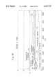
- the measurement data in FIG. 13 was obtained as follows:
- FIG. 14 was obtained as follows:
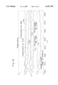
- FIG. 15 was obtained as follows: We projected light onto a previously selected measuring part of a patient's palm and received the reflected light to measure a reference energy spectrum (A). Then corresponding to the above (2) and (3), we measured energy spectra by pressing the optical fiber to the measuring part by 1, 2, 3, and 4 mm to add pressure instead of changing the location of the measuring part or the angle of irradiation. Then, as in the above (4), at the time when the patient's blood sugar changed to 15 mg/dl after the patient had drunk the above glucose tolerance test solution, we measured an energy spectrum. Then, as in the above (5) and (6), we obtained the curves h 21 , h 22 , h 23 , and h 24 of FIG. 15.
- monitors using a probe of the clipping method for acquiring information about organisms minutely differ in shape and size.
- a probe for the measurement of information about organisms For the method of sticking a probe for the measurement of information about organisms to the measuring part of an organism using double-sided adhesive tape, it is difficult to paste the form for the measurement of information about organisms exactly onto an originally selected measuring part of an organism. Therefore, it is difficult for the prior clipping method and double-sided adhesive tape method to maintain the above precision for reproduction, as we see from the measurement data in FIGS. 13 to 15.
- the prior clipping method and double-sided adhesive tape method to maintain the above precision for reproduction, as we see from the measurement data in FIGS. 13 to 15.
- the prior clipping method and double-sided adhesive tape method As a result, there has been a problem that the measurement results are so dispersed that results having sound reproducibility cannot be obtained.
- a monitor using a probe of the clipping method for acquiring information about organisms compresses a blood vessel and the like, when measuring the concentration of a particular component of an organism at its measuring part. Therefore, there has been a problem that the blood stream can be affected, so that stable measurements cannot be obtained.
- the size of the groove is determined by the average of the measuring parts of numerous organisms. Therefore, there has been a problem that it is difficult to respond to differences in size due to individual differences in the measuring parts of organisms having various sizes. In addition, there is another problem. In order to make the measuring part of an organism completely identical each time, the second dimension (the depth of the inserted part) can be corrected, but the third dimension (the height and the angle of the inserted part and the rotation of the measuring part) is difficult to correct.
- the users locate the measuring part with their eyes depending on the mark imprinted on the measuring part of an organism using a felt pen and the like. Therefore, if the marking disappears, then not only is the locating the measuring part impossible, but also the angle of the incident light with the measuring part of the organism and the contact pressure is different for each measurement. As a result, there has been a problem that a high degree of reproducibility is difficult to obtain.
- An object of the present invention is therefore to provide a method of restoring the measuring location such that light is projected onto the measuring part of the measured object under constant measurement conditions.
- Another object of the present invention is an optical measuring apparatus that can obtain measurements of high reliability having small dispersion among repeated measurements.
- the present invention projects measuring light onto a measured object and detects the spectral intensity of the light transmitted or reflected by the measured object to measure the concentration of a particular component within the measured object based on the spectral intensity, the present invention takes a picture of the measured object to display its image. Then the invention selects from the image a part that has a visually recognizable feature to mark the part and stores the marked image as a registered image. When restoring the measuring location, the present invention takes a picture of the measured object to compare the pattern of that image with the pattern of the registered image, detects the part on the taken image corresponding to the marked part of said registered image to determine the detected part as the measuring location for letting the measuring light incident thereon, and then executes the measurement.
- the present invention When registering the measuring location, the present invention takes a picture of the measured object to select and mark a part that has a visually recognizable feature and stores the marked image as a registered image. When restoring the measuring location, the present invention takes a picture of the measured object to compare the pattern of that image with the pattern of the registered image, and detects the part corresponding to the marked part of the registered image to project the measuring light thereon.
- the present invention also detects, by pattern recognition, the part corresponding to the marked part of the registered image, from the pattern of the image of the measured object taken during the restoration of the measuring location.
- the present invention detects, by pattern recognition, the part corresponding to the marked part of the registered image, from the pattern of the image of the measured object taken during the restoration of the measuring location.
- the present invention also permits detection, with the human eye, of the part corresponding to the marked part of the registered image, from the pattern of the image of the measured object taken during the restoration of the measuring location.
- the present invention further permits detection with the human eye, if the part coinciding with the marked part or the registered image, from the pattern of the image of the measured object taken during the restoration of the measuring location.
- the present invention also stores the marked image as a registered image together with information that identifies the measured object.
- the present invention identifies the measured object by the information stored with the registered image.
- the present invention also detects, from the pattern of the image obtained from taking a picture of an organism, a part having a feature, and projects measuring light onto the detected part.
- the present invention is further directed to a measuring apparatus having a projection optical system that projects measuring light onto a measured object.
- a measuring apparatus having a projection optical system that projects measuring light onto a measured object.
- the measuring apparatus projects the measuring light onto a predetermined measuring location.
- the measuring apparatus is equipped with a measured-object mounting means that mounts the measured object, an image pickup means that takes a picture of the measured object, an image display means that displays the image of the measured object, an image registration means that during the registration of the measuring location, stores as a registered image an image in which a part having a visually recognized feature is marked by selecting the part from the pattern of the image of the measured object displayed on the image display means, a moving means that during the restoration of the measuring location, compares the pattern of the registered image with the pattern of the currently taken image of the measured object, identifies the location of the part corresponding to the marked part of the registered image, in the currently taken image of the measured object, and moves the projection optical system or the measured object mounting means so that the measuring light should be projected onto the identified part.
- the measuring apparatus compares the pattern of the registered image with the pattern of the currently taken image of the measured object, detects the location of the part corresponding to the marked part of the registered image, in the currently taken image of the measured object, and moves the projection optical system or the measured object mounting means so that the measuring light should be projected onto the detected part.
- the projection optical system or the measured object mounting means moves in the directions of X axis and Y axes that are orthogonal to a Z axis that is oriented in the direction of the optical axis of the measuring light.
- the projection optical system or the measured object mounting means moves in the directions of the X axis and Y axis that are orthogonal to the Z axis that is oriented in the direction of the optical axis of the measuring light.
- the projection optical system moves in the direction of the Z axis.
- the projection optical system rotates around the Z axis.
- the measuring apparatus is equipped with a contact pressure sensor that detects contact pressure between the measured object and the measured object mounting means, a contact pressure memory that stores the output of the contact pressure sensor, and a pressurization device that reproduces the contact pressure stored in the contact pressure memory.
- the measuring apparatus detects contact pressure between the measured object and the measured object mounting means and reproduces the contact pressure stored in the contact pressure memory.
- the image registration means stores, as a registered image, the above marked image together with information that identifies the measured object.
- the measured object is identified by the information stored in the image registration means together with the registered image.
- the measured object is an organism.
- the measuring apparatus moves the projection optical system or the measured object mounting means so that the measuring light should be incident on the part selected from the pattern of the image obtained from taking a picture of an organism.
- the present invention is further directed to optical measuring apparatus having a projection optical system that projects measuring light onto a measured object.
- the optical measuring apparatus detects the spectral intensity of the light transmitted or reflected by the measured object to measure the concentration of a particular component within the measured object based on the spectral intensity.
- the optical measuring apparatus is equipped with a measured-object mounting means that mounts the measured object, an image pickup means that takes a picture of the measured object an image display means that displays the image of the measured object, an image registration means that during the registration of the measuring location, stores as a registered image an image in which a part having a visually recognized feature is marked by selecting the part from the pattern of the image of the measured object displayed on the image display means, a measuring location identifying means that during the restoration of the measuring location, compares the pattern of the registered image with the pattern of the currently taken image of the measured object, identifies the location of the part corresponding to the marked part of the registered image, in the currently taken image of the measured object, a moving means that moves the projection optical system so that the measuring light should be projected onto the part identified by the measuring location identifying means, a light receiving optical means that receives the light transmitted or reflected by the measuring part, a spectral intensity detecting means that detects the spectral intensity of the light transmitted or reflected by the measured object and received by the light receiving optical system
- the optical measuring apparatus compares the pattern of the registered image with the pattern of the currently taken image of the measured object, detects the location of the part corresponding to the marked part of the registered image, in the currently taken image of the measured object, and moves the projection optical system so that the measuring light should be projected onto the detected part.
- the optical measuring apparatus then receives the light transmitted or reflected by the measured object to detect the spectral intensity and detects the concentration of a particular component within the measured object based on the detected spectral intensity.
- the projection optical system has an optical fiber.
- the measuring light is projected onto the selected part of the measured object through the optical fiber.
- the light receiving optical system has an optical fiber.
- the light transmitted or reflected by the measured object is received through the optical fiber.
- the light receiving optical system has an integrating sphere.
- the light transmitted or reflected by the measured object is collected by the integrating sphere.
- the image registration means stores the marked image as a registered image together with information that identifies the measured object.
- the measured object is identified by the information stored in the image registration means together with a registered image.
- the measured object is an organism.
- the optical measuring apparatus moves the projection optical system or the measured object mounting means so that the measuring light should be incident on the part selected from the pattern of the taken image of an organism.
- the optical measuring apparatus measures the concentration of a particular component within the organism.
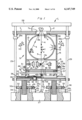
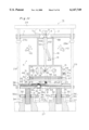
- FIG. 1 is a diagram illustrating the construction of the spectroscopic analyzer and its moving mechanism of a first embodiment of optical measuring apparatus in accordance with the present invention.
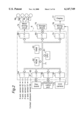
- FIG. 2 is a block diagram illustrating the construction of the arithmetic and control processor of the moving mechanism in the optical measuring apparatus of FIG. 1.
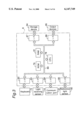
- FIG. 3 is a block diagram illustrating the arithmetic processor of the spectroscopic analyzer in the optical measuring apparatus of FIG. 1.
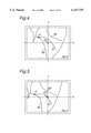
- FIG. 4 is a diagram illustrating a registered image of a feature part in the registration mode.
- FIG. 5 is a diagram illustrating the decision of a feature part in the measurement mode.
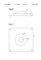
- FIG. 6 is a front view of the transformation of a mounting base.
- FIG. 7 is a top view of the mounting base in FIG. 6.
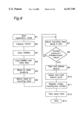
- FIG. 8 is a flowchart of the registration mode.
- FIG. 9 is a flowchart of the measurement mode.
- FIG. 10 is a flowchart of the measurement mode.
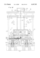
- FIG. 11 is a diagram illustrating the construction of the spectroscopic analyzer and its moving mechanism of a second embodiment of optical measuring apparatus in accordance with the present invention.
- FIG. 12 is a diagram illustrating the construction of the spectroscopic analyzer and its moving mechanism of a third embodiment of optical measuring apparatus in accordance with the present invention.
- FIG. 13 is measurement data illustrating changes in measurements of blood sugar due to changes in the incidence location of light incident on a measured object.
- FIG. 14 is measurement data illustrating changes in measurements of blood sugar due to changes in the incidence angle of light incident on a measured object.
- FIG. 15 is measurement data illustrating changes in measurements of blood sugar due to changes in contact pressure between a measured object and the mounting base.
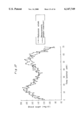
- FIG. 16 is a graph illustrating the CV values of measured spectra obtained from using a spectrometric apparatus in accordance with the present invention.
- ⁇ indicates the measurements obtained from fixing the location by a spectrometric apparatus of the present invention
- ⁇ indicates the measurements obtained from setting the location according to a method of the present invention
- ⁇ indicates the measurements obtained from replacement without using the present invention.
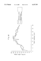
- FIG. 17 is a graph illustrating temporal changes in blood sugar.
- ⁇ indicates reference values (measured by drawing blood); and ⁇ indicates values obtained from fixing the measuring location by a spectrometric apparatus of the present invention.
- FIG. 18 is a graph illustrating temporal changes in blood sugar.
- ⁇ indicates reference values (measured by drawing blood); and ⁇ indicates values obtained from determining the measuring location according to a method of the present invention.
- FIGS. 1 to 3 illustrate the construction of an embodiment of optical measuring apparatus in accordance with the present invention.
- the optical measuring apparatus 1 is used for detecting the concentration of glucose from a human hand 2 that is the measured object.
- the optical measuring apparatus 1 is equipped with a spectroscopic analyzer 5 that projects measuring light 3 onto a human hand 2 to detect the spectral intensity of the reflected light 4, an arithmetic and control processor 6 (see FIG. 2) that controls the projecting location of the measuring light 3, an arithmetic processor 8 (see FIG. 3) that determines the glucose concentration based on the spectral intensity detected by the spectral analyzer 5, a moving mechanism 9 for the spectroscopic analyzer 5, and a CCD camera 11 (see FIGS. 1, 2) that takes a picture of the human hand 2 mounted on a mounting base 7.
- the spectral analyzer 5 is equipped with a projection optical system 12 that projects measuring light 3 onto the human hand 2 mounted on the mounting base 7 for the measured object, an integrating sphere 13 that collects the light 4 projected by the projection optical system 12 and reflected by the human hand 2, and a light receiving sensor 14 that detects the intensity of the reflected light 4 collected by the integrating sphere 13.
- the projection optical system 12 is housed in a lower compartment 15 of spectroscopic-analyzer 5.
- the integrating sphere 13 is housed in an upper compartment 16 of spectroscopic analyzer 5.
- the projection optical system 12 includes a light source 17, a collimator lens 18 that makes the light from the light source 17 parallel, a condenser lens 19 that condenses the parallel light emitted from the collimator lens 18, and a half mirror 21.
- the light source 17, collimator lens 18, and condenser lens 19 are set on the same optical axis.
- the half mirror 21 is set at an angle of 45 degrees with the optical axis. In this setting, the light emitted from light source 17 is reflected by the half mirror 21 in the direction having an angle 90 degrees with the optical axis.
- the measuring light is projected onto the human hand 2 through transmittance openings 13a, 13b formed on the integrating sphere 13 set on the upper side of the projection optical system 12 and a transmittance opening 7a formed on mounting base 7 set on the upper compartment 16.
- the light receiving sensor 14 is attached to integrating sphere 13 with its light receiving face directed toward the inside of the sphere. After being reflected by the human hand 2, the measuring light is collected by the integrating sphere and made incident on the light receiving sensor 14.
- a reference light sensor 92 that detects the intensity of the light emitted from light source 17 of the projection optical system 12.
- the reference light sensor 92 is set opposite to the light source 17 from half mirror 21 of the projection optical system 12. The light emitted from the light source 17 is made incident on the reference light sensor 92 after being transmitted by half mirror 21.
- the moving mechanism 9 for spectroscopic analyzer 5 is set under the lower compartment 15 of spectroscopic analyzer 5.
- the moving mechanism 9 supports the spectroscopic analyzer 5 so that the latter can move in the direction of the X axis that is vertical to the paper surface of FIG. 5 and in the direction of Y axis that is vertical to both the X axis and the Z axis that is oriented in the direction of the light path of the measuring light 3.
- the moving mechanism 9 supports spectroscopic analyzer 5 so that the latter can rotate around the Z axis.
- the moving mechanism 9 is equipped with an X-axis moving table 22, a Y-axis moving table 23, and a Z-axis moving table 24.
- the X-axis moving table 22 is supported by an X-axis rail 25 on the Y-axis moving table 23 so that the X-axis moving table can move in the direction of the X axis.
- the Y-axis moving table 23 is supported by a Y-axis rail 26 on the Z-axis moving table 24 so that the Y-axis moving table 23 can move in the direction of the Y axis.
- the Z-axis moving table 24 is directed by a binding member 29 that binds to a base 27 of spectroscopic analyzer 5 a pressing member 28 that presses the human hand 2 so that the Z-axis moving table 24 can rise from the corners of the base 27, which has a rectangular shape, and can move in the direction of the Z-axis.
- CCD camera 11 is set on the base 27.
- the CCD camera 11 is set so that when the spectroscopic analyzer 5 escapes from under the transmittance opening 7a by the moving mechanism 9 to an initial position, the optical axis of the CCD camera 11 should line up with the optical axis of the measuring light 3 in the spectroscopic analyzer 5.
- CCD camera 11 can direct its optical axis toward the human hand 2 illuminated by illuminating lamps 110 for pickup through transmittance openings 7a, 24a.
- the 2-axis moving table 24 is supported by screw shafts 31 that project downward from its lower surface, nuts 32 that mesh with screw shafts 31, and nuts supporting members 34 that rise from the base 27 and support the nuts 32 on the top so that nuts 32 can rotate.
- the teeth 32a formed on the circumferences of nuts 32 mesh with pinions 36 that are attached to the output shafts 35 of Z-axis driving motors Mz. Therefore, when the Z-axis driving motors Mz rotate, then nuts 32 are rotated through pinions 36, so that screw shafts 31 move in the direction of their own axes. Therefore, the Z-axis moving table 24 moves in the direction of the Z axis.
- the amount of the movement of the Z-axis moving table 24 in the direction of the Z axis is detected by revolution sensors 37 of revolutions (called Z-axis sensors hereafter) installed in the Z-axis driving motors Mz.
- the Y-axis moving table 23 is supported on the Z-axis moving table by the Y-axis rails 26 so that the Y-axis moving table 23 can freely move in the direction of the Y axis.
- Racks 38 are attached to the sides of the Y-axis moving table 23.
- Pinions 41 attached to the output shafts 39 of the Y-axis driving motors My mesh with the racks 38.
- the X-axis moving table 22 is supported on the Y-axis moving table 23 by the X-axis rails 25 so that the X-axis moving table 22 can freely move in the direction of the X axis.
- a rack 43 is attached to the underside of the X-axis moving table 22.
- a pinion 45 attached to the output shaft 44 of an X-axis driving motor Mx meshes with the rack 43.
- a rotary supporting mechanism 48 that supports the cylindrical lower compartment 15 and the upper compartment 16 of spectroscopic analyzer 5 so that they can rotate around their axis.
- the rotary supporting mechanism 48 includes directing members 51, 52 of a ring shape and ball bearings 53 that are inserted into circular grooves formed on the directing members 51, 52.
- a rack 54 is attached to the circumference of the lower compartment 15.
- a pinion 56 attached to the output shaft 55 of an ⁇ -axis driving motor M ⁇ meshes with the rack 54.
- the mounting base 7 that mounts the human hand 2 on itself is a simple plane having in its center the transmittance opening 7a for transmitting the measuring light 3.
- a contact pressure sensor 58 is fixed on the mounting base 7 opposite to the upper compartment 16 of the spectroscopic analyzer 5.
- the contact pressure sensor 58 generates a contact pressure signal corresponding to contact pressure between the human hand 2 and mounting base 7 as follows.
- the spectroscopic analyzer 5 moves up in the direction of the Z axis, so that the upper compartment 16 of the spectroscopic analyzer contacts the mounting base 7 that is stopped by contacting a stopper 29a formed on the binding member 29. Then the spectroscopic analyzer 5 further moves up together with the mounting base 7 in the direction of the Z-axis.
- the contact pressure sensor 58 generates the contact pressure signal.
- a protrusion 7b may be formed on the mounting base 7 to facilitate the locating of the human hand 2.
- Arithmetic and control processor 6 may be a microcomputer, which includes a central processing unit (written CPU hereafter) 61, a read-only memory (written ROM hereafter) 62, a read/write memory (written RAM hereafter) 63, and interface circuits 64 to 70.
- the CPU 61 is connected to ROM 62, RAM 63, and interface circuits 64 to 70 through a bus 71.
- Interface circuit 64 receives from X-axis sensor 46 an X-axis position signal of the X-axis moving table 22, from Y-axis sensor 42 a Y-axis position signal of the Y-axis moving table 23, from Z-axis sensor 37 a Z-axis position signal of the Z-axis moving table 24, from ⁇ -axis sensor 57 an ⁇ -axis rotary position signal, and from contact pressure sensor 58 a contact pressure signal.
- Interface circuit 65 receives from an operator key board 72 operator instruction signals necessary for interface circuit 65 corresponding to the operational contents of the keyboard input.
- Interface circuit 66 is connected to a communication port 73 for communication with the arithmetic processor 8 of FIG. 3.
- Interface circuit 67 is connected to CCD camera 11.
- Interface circuit 68 is connected to a motor driving circuit 74.
- the motor driving circuit 74 is connected to the X-axis driving motor Mx, Y-axis driving motors My, Z-axis driving motors Mz, and ⁇ -axis driving motor M ⁇ described above with reference to FIG. 1.
- Further Interface circuit 69 is connected to a storage device 75 such as a hard disk.
- Interface circuit 70 outputs into a mixing circuit 76 an image signal of the human hand 2 that has been registered before.
- the mixing circuit 76 mixes a video signal output from the CCD camera 11 and the image signal of the registered human hand 2 to output the resulting signal into a display 77.
- the arithmetic processor 8 of the spectroscopic analyzer 5 may be in a microcomputer, which includes a CPU 78, ROM 79, RAM 81 interface circuits 82 to 85, and interface circuits 87, 88.
- the CPU 78 is connected to the ROM 79, RAM 81, interface circuits 82 to 85, and interface circuits 87, 88 through a bus 89.
- the interface circuit 82 is connected to the keyboard 72 described above with reference to FIG. 2.
- Interface circuit 83 receives, from the light receiving sensor 14 described above with reference to FIG. 1, a spectral intensity signal of the reflected light 4 of measuring light 3 reflected by the human hand 2.
- interface circuit 84 is connected to a communication port 91 for communication with the arithmetic and control processor 6 of FIG. 2.
- Interface circuit 85 receives from the reference light sensor 92 a reference light signal as a reference signal.
- the reference light signal corresponds to the luminous intensity of light source 17 in the projection optical system 12 of spectroscopic analyzer 5 described above with reference to FIG. 1.
- Interface circuit 87 is connected to storage device 94 such as a hard disk.
- Interface circuit 88 is connected to output devices 95 such as a printer and CRT display.
- the construction of the location restoring apparatus of the optical measuring apparatus 1 has been described so far.
- the operation of the optical measuring apparatus 1 equipped with the location restoring apparatus is described together with a method of restoring the measuring location for a preselected location of the human hand 2.
- CPU 61 of arithmetic and control processor 6 loads RAM 63 through interface circuit 69 with the initial data for X-axis moving table 22, Y-axis moving table 23, Z-axis moving table 24, and the angle of ⁇ -axis rotation that is stored in storage device 75 (#4). These X-axis moving table 22, Y-axis moving table 23, Z-axis moving table 24, and the angle of ⁇ -axis rotation are moved to their initial locations (#5).
- the human hand 2 is mounted on mounting base 7 (#6).
- Mounting base 7 is moved in the direction of the Z axis toward the pressing member 28 (#7).
- the mounting base 7 is stopped (#8).
- CCD camera 11 takes a picture of the human hand 2 to display its image on display 77 (#9).
- An example of the displayed image on display 77 is illustrated in FIG. 4.
- the operator selects a visually recognized feature point P with a pointing device such as a trackball accompanied with keyboard 72 to display the feature point P with the symbol x (#10).
- a pointing device such as a trackball accompanied with keyboard 72
- the center point P 0 of the displayed image corresponds to the origin of the X-Y plane where the X axis and Y axis intersect each other.
- the above pattern of the displayed image is stored in storage device 75 together with the symbol x marked on the feature point P, the contact pressure signal output from contact pressure sensor 58, and a registration number that identifies the human hand 2, say No. 3 as shown in FIG. 4 (#11). After that, mounting base 7 goes down, and the human hand 2 is taken away from mounting base 7 (#12). Then the registration mode is terminated (#13).
- the measurement routine starts (#21). Then CPU 61 of arithmetic and control processor 6 is initialized (#22), and RAM 63 is cleared (#23). Next, CPU 78 of arithmetic processor 8 in spectroscopic analyzer 5 is initialized, and RAM 81 is cleared (#24).
- CPU 61 of arithmetic and control processor 6 loads RAM 63 through interface circuit 69 with the initial data of X-axis moving table 22, Y-axis moving table 23, Z-axis moving table 24, and the angle of ⁇ -axis rotation that are stored in storage device 75 (#25). These X-axis moving table 22, Y-axis moving table 23, Z-axis moving table 24, and the angle of ⁇ -axis rotation are moved to their initial locations based on the initial data (#26).
- the human hand 2 of the registration No. 3 is mounted on the mounting base 7 (#28).
- the Z-axis moving table 24 is moved up in the direction of the Z-axis until the human hand contacts the pressing member 28, and the contact pressure between human hand 2 and mounting base 7 output from contact pressure sensor 58 becomes the value registered in the registration mode (#28a and #29).
- CCD camera 11 displays the video signal of the palm of the human hand 2 on display 77 through mixing circuit 76 (#30).
- An example of the image displayed on the display 77 at this time is illustrated in FIG. 5.
- the CPU 61 of arithmetic and control processor 6 takes in the image signal of the palm of the human hand 2 output from CCD camera 11 to perform image processing.
- CPU 61 compares the pattern of the taken image of the palm of the human hand 2 with the image pattern of the palm of the human hand 2, No. 3, registered in the registration mode, and detects the feature point P registered in the registration mode from the image pattern of the palm of the human hand 2, No. 3, currently displayed on display 77 (#31).
- the feature point P may be detected from the image of the palm of the human hand 2, No. 3, currently displayed on display 77 by the operator with his or her eyes as follows.
- the image signal of the palm of the human hand 2, No. 3, currently displayed on display 77 is mixed with the image signal of the palm of the human hand 2, No. 3, registered in the registration mode by mixing circuit 76, and both images are superimposed over each other on the display 77.
- the operators can detect with their eyes the feature point P registered in the registration mode, in the current image of the palm of the human hand 2, No. 3.
- the software for pattern recognition becomes unnecessary in this way, so that the manufacturing costs for developing measurement software for the optical measuring apparatus can be cut down.
- CPU 61 of arithmetic and control processor 6 After detecting the feature point P from the image pattern of the palm of the human hand 2 currently displayed on the display 77, CPU 61 of arithmetic and control processor 6 moves X-axis moving table 22 and Y-axis moving table 23 in the directions of the X axis and the Y axis respectively, to make the optical axis of the measuring light of spectroscopic analyzer 5 agree with the detected feature point P (#32).
- the arithmetic and control processor 6 monitors the incident spot diameter of the measuring light 3 incident on the human hand 2 with display 77 and corrects the incident spot diameter by rotating spectroscopic analyzer 5 around the Z- axis with the ⁇ -axis driving motor M ⁇ .
- the location of spectroscopic analyzer 5 is determined so that the measuring light 3 should be incident on the registered feature point P of the palm of the human hand 2.
- CPU 61 of arithmetic and control processor 6 outputs a spectrometry starting signal to CPU 78 of arithmetic processor 8 in spectroscopic analyzer 5 through the interface circuit 66, communication port 73 and through the communication port 91 and interface circuit 84 of arithmetic processor 8 (#33).
- CPU 78 of arithmetic processor 8 in spectroscopic analyzer 5 receives the spectrometry starting signal from CPU 61 of arithmetic and control processor 6, CPU 78 executes the computation of the absorbance for the palm of the human hand 2 based on the spectral intensity signal of the reflected light 4 reflected from the feature point P of the palm of the human hand 2 and output from light receiving sensor 14 and the spectral intensity of light source 17 output from reference light sensor 92 (#34). Next, CPU 78 executes the computation of the glucose concentration based on the results of the absorbance computation (#35) to output the obtained glucose concentration into output devices 95 (#36)
- CPU 78 of arithmetic processor 8 outputs to CPU 61 of arithmetic and control processor 6 a measurement termination signal for glucose concentration through the interface circuit 84 and communication port 91 and through the communication port 73 and interface circuit 66 of arithmetic and control processor 6.
- CPU 61 of arithmetic and control processor 6 moves X-axis moving table 22, Y-axis moving table 23 and Z-axis moving table 24 to their initial locations (#37).
- the human hand 2 No. 3 is taken away from mounting base 7 (#38), and a first measurement of glucose concentration is completed (#39).
- the subsequent measurements of glucose concentration on and after a second time are conducted following the steps 21 to #39.
- the present embodiment sets the human hand 2 on the measured object mounting base 7 of spectroscopic analyzer 5 and takes a picture of the measured object with a camera to select the measuring point P having a feature from the pattern of the image, so that the present embodiment can make the measuring light 3 incident on the measuring point P at each measuring time after that.
- the present embodiment can greatly improve the reproducibility for the measuring location and lower the dispersion of the measurements due to changes in the measuring location.
- FIGS. 16, 17, and 18 illustrate some results obtained by the measurement using a measuring apparatus of the present embodiment in accordance with the present invention.
- FIG. 16 illustrates the CV values (%), that is, (standard deviation/average) ⁇ 100 (%), of three kinds of spectra obtained from a human hand.
- the figure shows that the measurements indicated by ⁇ and obtained from fixing the location agree extremely well with the measurements indicated by ⁇ and obtained from setting the location according to the method of the present invention. In contrast, the measurements obtained from simple replacement without using the present invention greatly depart from the measurements obtained from fixing the location.
- FIG. 17 illustrates temporal changes in blood sugar in a case where we let the patient drink a glucose tolerance test solution, Trelan 75, manufactured by Shimizu Pharmaceutical Co. The figure shows that the measurements for a human hand soundly agree with reference values (blood sugar measured by drawing blood).
- FIG. 18 illustrates the measurement results obtained from determining the measuring location following the present invention from the registered image and the currently taken image.
- the measurement results indicated by ⁇ agree extremely well with reference values indicated by ⁇ .
- the data indicated by represents the expected values obtained by a publicly-known computer simulation and greatly shifts from the reference values compared with the measurement results due to the present invention.
- FIG. 11 illustrates the optical measuring apparatus of a second embodiment in accordance with the present invention.
- the optical measuring apparatus la projects the light of the projection optical system 12 onto the human hand 2 set on the mounting base 7, in the optical measuring apparatus 1 of the first embodiment, through an optical fiber 101, and directs the reflected light 4 reflected by the human hand 2, in place of the integrating sphere 13 of the measuring apparatus 1 of FIG. 1, through an optical fiber 102 into the light receiving sensor 14.
- the construction of the part other than the optical fibers 101, 102 is the same as the corresponding part of the optical measuring apparatus 1 described with reference to FIG. 1. Therefore, in FIG. 11, the components corresponding to those in FIG. 1 are denoted by the same numerals, and redundant descriptions are omitted.
- the shape of the optical measuring apparatus la becomes compact by the use of optical fibers 101, 102.
- the construction becomes simple. The handling of the apparatus becomes easier.
- FIG. 12 illustrates the optical measuring apparatus of another embodiment in accordance with the present invention.
- the optical measuring apparatus lb forms an opening 105 at the location of the pressing member 28 opposite to the transmittance opening 7a of the mounting base 7, in the optical measuring apparatus of the second embodiment described with reference to FIG. 11.
- the optical measuring apparatus 1b directs the light transmitted by the human hand 2 into a light receiving sensor 14 through the opening 105 and an optical fiber 102.
- the construction of the part other than the arrangement of the optical fiber is the same as the corresponding part of the optical measuring apparatus 1a described with reference to FIG. 11. Therefore, in FIG. 12, the components corresponding to those in FIG. 11 are denoted by the same numerals, and redundant descriptions are omitted. According to this construction, the transmitted light transmitted by the human hand 2 can be detected with the optical measuring apparatus lb of a compact shape by the use of the optical fibers 101, 102, so that the glucose concentration can be measured based on the detected transmitted light.
- the present invention when restoring the measuring location, the present invention takes a picture of the measured object to compare the pattern of that image with the pattern of the registered image and detects the part of the measured object corresponding to the marked part of the registered image. Therefore, the measuring location can be restored with a high degree of reproducibility.
- the present invention further detects by pattern recognition the part corresponding to the marked part of the registered image, from the pattern of the image of the measured object taken during the restoration of the measuring location. Therefore, the measuring location can be restored with a high degree of reproducibility without depending on human eyes.
- the present invention further detects with human eyes the part corresponding to the marked part of the registered image, from the pattern of the image of the measured object during the restoration of the measuring location. Therefore, the measuring location can be easily restored.
- the present invention further stores information that identifies the measured object together with the marked image, so that the measured object having the mark can be easily identified.
- the present invention further detects, from the pattern of the image obtained from taking a picture of an organism, a part on the organism corresponding to the marked part of the registered image having a feature to determine the measuring location. Therefore, when the concentration of a particular component within the organism is detected based on the transmitted or reflected light by projecting the measuring light onto the organism, the measuring location can be restored with a high degree of reproducibility.
- the optical measuring apparatus compares the pattern of the registered image with the pattern of the currently taken image of the measured object, detects the location of the part corresponding to the marked part of the registered image, in the currently taken image of the measured object, and moves the projection optical system so that the measuring light should be projected onto the detected part. Therefore, the measuring location can be restored with a high degree of reproducibility.
- the projection optical system or the measured object mounting means moves in the directions of the X axis and Y axis that are orthogonal to the Z axis that is oriented in the direction of the optical axis of the measuring light. Therefore, the measured object can be moved in the directions of two dimensions during each measurement so that the measuring location of the measured object can be restored at a fixed place.
- the projection optical system moves in the direction of the Z axis. Therefore, the positional relation in the direction of the Z axis between the projection optical system and the measured object during the registration of the registered image can be restored.
- the projection optical system rotates around the Z axis. Therefore, the incident spot diameter of the measuring light incident on the measured object during measurement can be corrected.
- the measuring apparatus detects contact pressure between the measured object and the measured object mounting means, with a contact pressure sensor and reproduces the contact pressure stored in a contact pressure memory during measurement. Therefore, changes in contact pressure between the measured object and the measured object mounting base can be reduced, so that the measuring location can be restored with a higher degree of reproducibility.
- the optical measuring apparatus stores in an image registration means information that identifies the measured object together with the marked image. Therefore, the measured object having the marked image can be easily identified.
- the optical measuring apparatus moves the projection optical system or the measured object mounting means so that the measuring light should be incident on the part selected from the pattern of the image obtained from taking a picture of an organism. Therefore, the location of a part selected from the pattern of the image obtained from taking a picture of an organism can be restored with a high degree of reproducibility.
- the optical measuring apparatus compares the pattern of the registered image with the pattern of the currently taken image of the measured object, detects the location of the part corresponding to the marked part of the registered image, in the currently taken image of the measured object, and moves the projection optical system so that the measuring light should be projected onto the detected part.
- the optical measuring apparatus then receives the light transmitted or reflected by the measured object to detect the spectral intensity and detects the concentration of a particular component within the measured object based on the detected spectral intensity. Therefore, the reproducibility for the incidence location for the measuring light incident on the measuring part of an organism can be made great.
- the optical measuring apparatus projects the measuring light onto a selected part of the measured object through an optical fiber. Therefore, the degree of freedom for setting the projection optical system becomes higher owing to the flexibility of the optical fiber, and the optical measuring apparatus becomes compact.
- the optical measuring apparatus receives the light transmitted or reflected by the measured object through an optical fiber. Therefore, the degree of freedom for setting the receiving optical system becomes higher owing to the flexibility of the optical fiber, and the optical measuring apparatus becomes compact.
- the optical measuring apparatus collects the light transmitted or reflected by the measured object with an integrating sphere. Therefore, the construction is comparatively simple, and manufacturing costs for optical measuring apparatus become low.
- the optical measuring apparatus stores in an image registration means information that identifies the measured object together with the marked image. Therefore, the measured object having the marked image can be easily identified.
- the optical measuring apparatus moves the projection optical system or the measured object mounting means so that the measuring light should be incident on the part selected from the pattern of the taken image of an organism.
- the optical measuring apparatus measures the concentration of a particular component within the organism. Therefore, the reproducibility for the incidence location for the measuring light incident on the measuring part of an organism can be made great, so that an optical measuring apparatus having small dispersion of measurements and great reliability can be obtained.
Abstract
Description
(E)={(A)/(A)}×100, (F)={(B)/(A)}×100,
(G)={(C)/(A)}×100, (H)={(D)/(A)}×100.
Claims (14)
Applications Claiming Priority (3)
| Application Number | Priority Date | Filing Date | Title |
|---|---|---|---|
| JP7-200950 | 1995-08-07 | ||
| JP20095095A JP3579686B2 (en) | 1995-08-07 | 1995-08-07 | Measuring position reproducing method, measuring position reproducing device, and optical measuring device using the same |
| PCT/JP1996/002223 WO1997006423A1 (en) | 1995-08-07 | 1996-08-07 | Method and apparatus for measuring light projection concentration |
Publications (1)
| Publication Number | Publication Date |
|---|---|
| US6147749A true US6147749A (en) | 2000-11-14 |
Family
ID=16433011
Family Applications (1)
| Application Number | Title | Priority Date | Filing Date |
|---|---|---|---|
| US08/817,085 Expired - Lifetime US6147749A (en) | 1995-08-07 | 1996-08-07 | Method and apparatus for measuring concentration by light projection |
Country Status (6)
| Country | Link |
|---|---|
| US (1) | US6147749A (en) |
| EP (1) | EP0801297A4 (en) |
| JP (1) | JP3579686B2 (en) |
| KR (1) | KR970706485A (en) |
| CN (1) | CN1165556A (en) |
| WO (1) | WO1997006423A1 (en) |
Cited By (30)
| Publication number | Priority date | Publication date | Assignee | Title |
|---|---|---|---|---|
| US6574490B2 (en) | 2001-04-11 | 2003-06-03 | Rio Grande Medical Technologies, Inc. | System for non-invasive measurement of glucose in humans |
| US6718189B2 (en) | 1995-08-09 | 2004-04-06 | Rio Grande Medical Technologies, Inc. | Method and apparatus for non-invasive blood analyte measurement with fluid compartment equilibration |
| US6816605B2 (en) | 1999-10-08 | 2004-11-09 | Lumidigm, Inc. | Methods and systems for biometric identification of individuals using linear optical spectroscopy |
| US20050134853A1 (en) * | 2003-12-19 | 2005-06-23 | Applied Color Systems, Inc. | Spectrophotometer with digital camera |
| WO2007072356A2 (en) * | 2005-12-21 | 2007-06-28 | Koninkijke Philips Electronics N.V. | Positioning system for patient monitoring sensors |
| US20080249380A1 (en) * | 2004-05-06 | 2008-10-09 | Koninklijke Philips Electronics, N.V. | Protection Mechanism for Spectroscopic Analysis of Biological Tissue |
| US20080262324A1 (en) * | 2004-05-11 | 2008-10-23 | Koninklijke Philips Electronics, N.V. | Measurement Head For Non-Invasive Blood Analysis |
| US20090318786A1 (en) * | 2002-03-08 | 2009-12-24 | Blank Thomas B | Channeled tissue sample probe method and apparatus |
| US7668350B2 (en) | 2003-04-04 | 2010-02-23 | Lumidigm, Inc. | Comparative texture analysis of tissue for biometric spoof detection |
| US7697966B2 (en) | 2002-03-08 | 2010-04-13 | Sensys Medical, Inc. | Noninvasive targeting system method and apparatus |
| US7735729B2 (en) | 2003-04-04 | 2010-06-15 | Lumidigm, Inc. | Biometric sensor |
| US7751594B2 (en) | 2003-04-04 | 2010-07-06 | Lumidigm, Inc. | White-light spectral biometric sensors |
| US7787924B2 (en) | 2002-03-08 | 2010-08-31 | Sensys Medical, Inc. | Compact apparatus for noninvasive measurement of glucose through near-infrared spectroscopy |
| US7801338B2 (en) | 2005-04-27 | 2010-09-21 | Lumidigm, Inc. | Multispectral biometric sensors |
| US7801339B2 (en) | 2006-07-31 | 2010-09-21 | Lumidigm, Inc. | Biometrics with spatiospectral spoof detection |
| US7804984B2 (en) | 2006-07-31 | 2010-09-28 | Lumidigm, Inc. | Spatial-spectral fingerprint spoof detection |
| US7831072B2 (en) | 2004-06-01 | 2010-11-09 | Lumidigm, Inc. | Multispectral imaging biometrics |
| US7890158B2 (en) | 2001-06-05 | 2011-02-15 | Lumidigm, Inc. | Apparatus and method of biometric determination using specialized optical spectroscopy systems |
| US7899217B2 (en) | 2006-07-19 | 2011-03-01 | Lumidign, Inc. | Multibiometric multispectral imager |
| US7995808B2 (en) | 2006-07-19 | 2011-08-09 | Lumidigm, Inc. | Contactless multispectral biometric capture |
| US8175346B2 (en) | 2006-07-19 | 2012-05-08 | Lumidigm, Inc. | Whole-hand multispectral biometric imaging |
| US8229185B2 (en) | 2004-06-01 | 2012-07-24 | Lumidigm, Inc. | Hygienic biometric sensors |
| US8285010B2 (en) | 2007-03-21 | 2012-10-09 | Lumidigm, Inc. | Biometrics based on locally consistent features |
| US8355545B2 (en) | 2007-04-10 | 2013-01-15 | Lumidigm, Inc. | Biometric detection using spatial, temporal, and/or spectral techniques |
| US8570149B2 (en) | 2010-03-16 | 2013-10-29 | Lumidigm, Inc. | Biometric imaging using an optical adaptive interface |
| US8718738B2 (en) | 2002-03-08 | 2014-05-06 | Glt Acquisition Corp. | Method and apparatus for coupling a sample probe with a sample site |
| US8731250B2 (en) | 2009-08-26 | 2014-05-20 | Lumidigm, Inc. | Multiplexed biometric imaging |
| US8787630B2 (en) | 2004-08-11 | 2014-07-22 | Lumidigm, Inc. | Multispectral barcode imaging |
| US8868147B2 (en) | 2004-04-28 | 2014-10-21 | Glt Acquisition Corp. | Method and apparatus for controlling positioning of a noninvasive analyzer sample probe |
| US11559223B2 (en) | 2014-10-29 | 2023-01-24 | Samsung Electronics Co., Ltd | Glucose measuring apparatus and method |
Families Citing this family (19)
| Publication number | Priority date | Publication date | Assignee | Title |
|---|---|---|---|---|
| US5851181A (en) * | 1996-08-30 | 1998-12-22 | Esc Medical Systems Ltd. | Apparatus for simultaneously viewing and spectrally analyzing a portion of skin |
| JP4214324B2 (en) * | 1997-08-20 | 2009-01-28 | アークレイ株式会社 | Biological tissue measurement device |
| JP3777415B2 (en) * | 1997-09-01 | 2006-05-24 | アークレイ株式会社 | Measuring site positioning method and jig |
| JPH11151229A (en) * | 1997-11-21 | 1999-06-08 | Kdk Corp | Non-contact and non-invasive measurement method and device therefor |
| DE19816487A1 (en) | 1998-04-14 | 1999-10-21 | Bodenseewerk Perkin Elmer Co | Device for detecting a fluorescent dye |
| US20020058864A1 (en) * | 2000-11-13 | 2002-05-16 | Mansfield James R. | Reduction of spectral site to site variation |
| US6694169B2 (en) * | 2001-02-22 | 2004-02-17 | Minrad Inc. | Targeting system and method of targeting |
| CN1203809C (en) * | 2002-11-22 | 2005-06-01 | 天津市先石光学技术有限公司 | Measurement condition reproducing device and method based on body's surface texture characteristic and contact pressure |
| JP4236950B2 (en) | 2003-02-13 | 2009-03-11 | シスメックス株式会社 | Non-invasive living body measurement device |
| CN100527155C (en) * | 2004-07-28 | 2009-08-12 | 北京大学 | Device for capturing palm print image based on photo optics |
| US7248907B2 (en) * | 2004-10-23 | 2007-07-24 | Hogan Josh N | Correlation of concurrent non-invasively acquired signals |
| JP5583340B2 (en) * | 2005-04-18 | 2014-09-03 | ガスポロックス エイビー | Body cavity gas measuring device and measuring method |
| CN102138783B (en) * | 2011-03-17 | 2013-02-13 | 中国科学院自动化研究所 | Signal acquisition positioning system |
| EP2832304A4 (en) * | 2012-03-29 | 2015-11-11 | Hitachi Medical Corp | Biological light measurement device, biological light measurement method, and engagement member for mobile position sensor |
| KR102335770B1 (en) | 2014-11-28 | 2021-12-06 | 삼성전자주식회사 | Devices and methods for noninvasive physiological analysis |
| CN107334477A (en) * | 2017-05-02 | 2017-11-10 | 北京理工大学深圳研究院 | A kind of double spectrum noninvasive dynamics monitoring devices |
| TWI773972B (en) * | 2020-03-05 | 2022-08-11 | 緯創資通股份有限公司 | Optical sensing device |
| WO2022009577A1 (en) * | 2020-07-06 | 2022-01-13 | Look Tec株式会社 | Blood measurement device |
| CN113925486A (en) * | 2020-07-14 | 2022-01-14 | 先阳科技有限公司 | Tissue component measurement method, tissue component measurement device, electronic apparatus, tissue component measurement system, and storage medium |
Citations (17)
| Publication number | Priority date | Publication date | Assignee | Title |
|---|---|---|---|---|
| US4000417A (en) * | 1975-08-25 | 1976-12-28 | Honeywell Inc. | Scanning microscope system with automatic cell find and autofocus |
| US4171866A (en) * | 1978-04-20 | 1979-10-23 | Tolles Walter E | Disposable volumetric slide |
| US4513438A (en) * | 1982-04-15 | 1985-04-23 | Coulter Electronics, Inc. | Automated microscopy system and method for locating and re-locating objects in an image |
| US4700298A (en) * | 1984-09-14 | 1987-10-13 | Branko Palcic | Dynamic microscope image processing scanner |
| JPH01184447A (en) * | 1988-01-19 | 1989-07-24 | Hamamatsu Photonics Kk | Object measuring instrument |
| JPH03167460A (en) * | 1989-11-28 | 1991-07-19 | Shimadzu Corp | X-ray microanalyzer |
| WO1992000513A1 (en) * | 1990-06-27 | 1992-01-09 | Futrex, Inc. | Non-invasive measurement of blood glucose |
| WO1992003965A1 (en) * | 1990-08-29 | 1992-03-19 | Cadell Theodore E | Finger receptor |
| JPH04109932A (en) * | 1990-08-31 | 1992-04-10 | Shimadzu Corp | Living body magnetism measuring device |
| JPH0510806A (en) * | 1991-07-03 | 1993-01-19 | Hitachi Medical Corp | X-ray device for x-ray equipment for inspecting quantity of liquid |
| JPH0614906A (en) * | 1992-06-30 | 1994-01-25 | Minolta Camera Co Ltd | Probe for living body information measurement |
| DE4341063A1 (en) * | 1992-12-09 | 1994-06-16 | Zeiss Carl Fa | Optical position resolving and detection appts. for density distribution in biological tissue - emits locally-limited beam from point source, registers position and angle of emitted beam, and analyses scattered light distribution regarding phase and amplitude of HF modulated beam |
| EP0623306A1 (en) * | 1993-05-07 | 1994-11-09 | Diasense, Inc. | Method for non-invasive measurement of concentration of analytes in blood using continuous spectrum radiation |
| WO1995005599A1 (en) * | 1993-08-16 | 1995-02-23 | Eli Lilly And Company | Non-invasive near-infrared quantitative measurement instrument |
| US5446548A (en) * | 1993-10-08 | 1995-08-29 | Siemens Medical Systems, Inc. | Patient positioning and monitoring system |
| US5531520A (en) * | 1994-09-01 | 1996-07-02 | Massachusetts Institute Of Technology | System and method of registration of three-dimensional data sets including anatomical body data |
| US5601079A (en) * | 1992-03-12 | 1997-02-11 | Wong; Jacob Y. | Non-invasive quantification of glucose control, aging, and advanced maillard products by stimulated fluorescence |
Family Cites Families (1)
| Publication number | Priority date | Publication date | Assignee | Title |
|---|---|---|---|---|
| JPH0510806Y2 (en) * | 1987-11-13 | 1993-03-17 |
-
1995
- 1995-08-07 JP JP20095095A patent/JP3579686B2/en not_active Expired - Fee Related
-
1996
- 1996-08-07 KR KR1019970702251A patent/KR970706485A/en not_active Application Discontinuation
- 1996-08-07 WO PCT/JP1996/002223 patent/WO1997006423A1/en not_active Application Discontinuation
- 1996-08-07 EP EP96926579A patent/EP0801297A4/en not_active Withdrawn
- 1996-08-07 CN CN96191151A patent/CN1165556A/en active Pending
- 1996-08-07 US US08/817,085 patent/US6147749A/en not_active Expired - Lifetime
Patent Citations (22)
| Publication number | Priority date | Publication date | Assignee | Title |
|---|---|---|---|---|
| US4000417A (en) * | 1975-08-25 | 1976-12-28 | Honeywell Inc. | Scanning microscope system with automatic cell find and autofocus |
| US4171866A (en) * | 1978-04-20 | 1979-10-23 | Tolles Walter E | Disposable volumetric slide |
| US4513438A (en) * | 1982-04-15 | 1985-04-23 | Coulter Electronics, Inc. | Automated microscopy system and method for locating and re-locating objects in an image |
| US4700298A (en) * | 1984-09-14 | 1987-10-13 | Branko Palcic | Dynamic microscope image processing scanner |
| JPH01184447A (en) * | 1988-01-19 | 1989-07-24 | Hamamatsu Photonics Kk | Object measuring instrument |
| JPH03167460A (en) * | 1989-11-28 | 1991-07-19 | Shimadzu Corp | X-ray microanalyzer |
| JPH05508336A (en) * | 1990-06-27 | 1993-11-25 | ファトレックス・インコーポレイテッド | Non-invasive measurement of blood sugar levels |
| US5436455A (en) * | 1990-06-27 | 1995-07-25 | Futrex Inc. | Non-invasive near-infrared quantitative measurement instrument |
| WO1992000513A1 (en) * | 1990-06-27 | 1992-01-09 | Futrex, Inc. | Non-invasive measurement of blood glucose |
| JPH06503728A (en) * | 1990-08-29 | 1994-04-28 | カデル、セオドアー・イー | finger rest device |
| WO1992003965A1 (en) * | 1990-08-29 | 1992-03-19 | Cadell Theodore E | Finger receptor |
| JPH04109932A (en) * | 1990-08-31 | 1992-04-10 | Shimadzu Corp | Living body magnetism measuring device |
| JPH0510806A (en) * | 1991-07-03 | 1993-01-19 | Hitachi Medical Corp | X-ray device for x-ray equipment for inspecting quantity of liquid |
| US5601079A (en) * | 1992-03-12 | 1997-02-11 | Wong; Jacob Y. | Non-invasive quantification of glucose control, aging, and advanced maillard products by stimulated fluorescence |
| JPH0614906A (en) * | 1992-06-30 | 1994-01-25 | Minolta Camera Co Ltd | Probe for living body information measurement |
| DE4341063A1 (en) * | 1992-12-09 | 1994-06-16 | Zeiss Carl Fa | Optical position resolving and detection appts. for density distribution in biological tissue - emits locally-limited beam from point source, registers position and angle of emitted beam, and analyses scattered light distribution regarding phase and amplitude of HF modulated beam |
| US5610399A (en) * | 1992-12-09 | 1997-03-11 | Carl-Zeiss-Stiftung | Apparatus and process for the spatially resolved optical determination of density distributions in biological tissues |
| US5460177A (en) * | 1993-05-07 | 1995-10-24 | Diasense, Inc. | Method for non-invasive measurement of concentration of analytes in blood using continuous spectrum radiation |
| EP0623306A1 (en) * | 1993-05-07 | 1994-11-09 | Diasense, Inc. | Method for non-invasive measurement of concentration of analytes in blood using continuous spectrum radiation |
| WO1995005599A1 (en) * | 1993-08-16 | 1995-02-23 | Eli Lilly And Company | Non-invasive near-infrared quantitative measurement instrument |
| US5446548A (en) * | 1993-10-08 | 1995-08-29 | Siemens Medical Systems, Inc. | Patient positioning and monitoring system |
| US5531520A (en) * | 1994-09-01 | 1996-07-02 | Massachusetts Institute Of Technology | System and method of registration of three-dimensional data sets including anatomical body data |
Cited By (42)
| Publication number | Priority date | Publication date | Assignee | Title |
|---|---|---|---|---|
| US6718189B2 (en) | 1995-08-09 | 2004-04-06 | Rio Grande Medical Technologies, Inc. | Method and apparatus for non-invasive blood analyte measurement with fluid compartment equilibration |
| US9487398B2 (en) | 1997-06-09 | 2016-11-08 | Hid Global Corporation | Apparatus and method of biometric determination using specialized optical spectroscopy systems |
| US6816605B2 (en) | 1999-10-08 | 2004-11-09 | Lumidigm, Inc. | Methods and systems for biometric identification of individuals using linear optical spectroscopy |
| US6574490B2 (en) | 2001-04-11 | 2003-06-03 | Rio Grande Medical Technologies, Inc. | System for non-invasive measurement of glucose in humans |
| US7890158B2 (en) | 2001-06-05 | 2011-02-15 | Lumidigm, Inc. | Apparatus and method of biometric determination using specialized optical spectroscopy systems |
| US7787924B2 (en) | 2002-03-08 | 2010-08-31 | Sensys Medical, Inc. | Compact apparatus for noninvasive measurement of glucose through near-infrared spectroscopy |
| US20090318786A1 (en) * | 2002-03-08 | 2009-12-24 | Blank Thomas B | Channeled tissue sample probe method and apparatus |
| US8718738B2 (en) | 2002-03-08 | 2014-05-06 | Glt Acquisition Corp. | Method and apparatus for coupling a sample probe with a sample site |
| US7697966B2 (en) | 2002-03-08 | 2010-04-13 | Sensys Medical, Inc. | Noninvasive targeting system method and apparatus |
| US7735729B2 (en) | 2003-04-04 | 2010-06-15 | Lumidigm, Inc. | Biometric sensor |
| US7668350B2 (en) | 2003-04-04 | 2010-02-23 | Lumidigm, Inc. | Comparative texture analysis of tissue for biometric spoof detection |
| US7751594B2 (en) | 2003-04-04 | 2010-07-06 | Lumidigm, Inc. | White-light spectral biometric sensors |
| US8184873B2 (en) | 2003-04-04 | 2012-05-22 | Lumidigm, Inc. | White-light spectral biometric sensors |
| US7819311B2 (en) | 2003-04-04 | 2010-10-26 | Lumidigm, Inc. | Multispectral biometric sensor |
| US7230707B2 (en) * | 2003-12-19 | 2007-06-12 | Datacolor Holding Ag | Spectrophotometer with digital camera |
| US20050134853A1 (en) * | 2003-12-19 | 2005-06-23 | Applied Color Systems, Inc. | Spectrophotometer with digital camera |
| US8868147B2 (en) | 2004-04-28 | 2014-10-21 | Glt Acquisition Corp. | Method and apparatus for controlling positioning of a noninvasive analyzer sample probe |
| US20080249380A1 (en) * | 2004-05-06 | 2008-10-09 | Koninklijke Philips Electronics, N.V. | Protection Mechanism for Spectroscopic Analysis of Biological Tissue |
| US20080262324A1 (en) * | 2004-05-11 | 2008-10-23 | Koninklijke Philips Electronics, N.V. | Measurement Head For Non-Invasive Blood Analysis |
| US7761129B2 (en) * | 2004-05-11 | 2010-07-20 | Koninklijke Philips Electronics N.V. | Measurement head for non-invasive blood analysis |
| US7831072B2 (en) | 2004-06-01 | 2010-11-09 | Lumidigm, Inc. | Multispectral imaging biometrics |
| US8913800B2 (en) | 2004-06-01 | 2014-12-16 | Lumidigm, Inc. | Optical biometrics imaging with films |
| US8165357B2 (en) | 2004-06-01 | 2012-04-24 | Lumidigm, Inc. | Two camera biometric imaging |
| US7835554B2 (en) | 2004-06-01 | 2010-11-16 | Lumidigm, Inc. | Multispectral imaging biometrics |
| US8229185B2 (en) | 2004-06-01 | 2012-07-24 | Lumidigm, Inc. | Hygienic biometric sensors |
| US8787630B2 (en) | 2004-08-11 | 2014-07-22 | Lumidigm, Inc. | Multispectral barcode imaging |
| US7801338B2 (en) | 2005-04-27 | 2010-09-21 | Lumidigm, Inc. | Multispectral biometric sensors |
| WO2007072356A2 (en) * | 2005-12-21 | 2007-06-28 | Koninkijke Philips Electronics N.V. | Positioning system for patient monitoring sensors |
| WO2007072356A3 (en) * | 2005-12-21 | 2007-11-15 | Koninkl Philips Electronics Nv | Positioning system for patient monitoring sensors |
| US8831297B2 (en) | 2006-07-19 | 2014-09-09 | Lumidigm, Inc. | Contactless multispectral biometric capture |
| US8781181B2 (en) | 2006-07-19 | 2014-07-15 | Lumidigm, Inc. | Contactless multispectral biometric capture |
| US8175346B2 (en) | 2006-07-19 | 2012-05-08 | Lumidigm, Inc. | Whole-hand multispectral biometric imaging |
| US7995808B2 (en) | 2006-07-19 | 2011-08-09 | Lumidigm, Inc. | Contactless multispectral biometric capture |
| US7899217B2 (en) | 2006-07-19 | 2011-03-01 | Lumidign, Inc. | Multibiometric multispectral imager |
| US7801339B2 (en) | 2006-07-31 | 2010-09-21 | Lumidigm, Inc. | Biometrics with spatiospectral spoof detection |
| US7804984B2 (en) | 2006-07-31 | 2010-09-28 | Lumidigm, Inc. | Spatial-spectral fingerprint spoof detection |
| US8285010B2 (en) | 2007-03-21 | 2012-10-09 | Lumidigm, Inc. | Biometrics based on locally consistent features |
| US8355545B2 (en) | 2007-04-10 | 2013-01-15 | Lumidigm, Inc. | Biometric detection using spatial, temporal, and/or spectral techniques |
| US8731250B2 (en) | 2009-08-26 | 2014-05-20 | Lumidigm, Inc. | Multiplexed biometric imaging |
| US8872908B2 (en) | 2009-08-26 | 2014-10-28 | Lumidigm, Inc | Dual-imager biometric sensor |
| US8570149B2 (en) | 2010-03-16 | 2013-10-29 | Lumidigm, Inc. | Biometric imaging using an optical adaptive interface |
| US11559223B2 (en) | 2014-10-29 | 2023-01-24 | Samsung Electronics Co., Ltd | Glucose measuring apparatus and method |
Also Published As
| Publication number | Publication date |
|---|---|
| CN1165556A (en) | 1997-11-19 |
| KR970706485A (en) | 1997-11-03 |
| EP0801297A4 (en) | 1999-05-06 |
| WO1997006423A1 (en) | 1997-02-20 |
| JPH0949794A (en) | 1997-02-18 |
| EP0801297A1 (en) | 1997-10-15 |
| JP3579686B2 (en) | 2004-10-20 |
Similar Documents
| Publication | Publication Date | Title |
|---|---|---|
| US6147749A (en) | Method and apparatus for measuring concentration by light projection | |
| US8135447B2 (en) | Optical biological information measuring apparatus, optical biological information measuring method, biological information decision apparatus, program and recording medium | |
| US5187506A (en) | Method and apparatus for determining physiological parameters based on pupil response | |
| US7154592B2 (en) | Multiwavelength readhead for use in the determination of analytes in body fluids | |
| EP3026874B1 (en) | Body fluid testing component for analyte detection | |
| EP2195641B1 (en) | An apparatus and method for observing the surface of a sample | |
| US6232616B1 (en) | LCD panel test apparatus | |
| US20120230547A1 (en) | Eye tracking | |
| CN101322643B (en) | Instrument for measuring a refractive power | |
| WO2005089635A1 (en) | Aberrometer provided with a visual acuity testing system | |
| JP2002078683A (en) | Device and method for inspecting surface | |
| JP2008507694A (en) | Read head for optical diagnostic equipment | |
| JP2010504795A (en) | Equipment for optically analyzing the body | |
| CN114729900A (en) | Method and device for performing analytical measurements | |
| US6473190B1 (en) | Optical volume sensor | |
| JP5274829B2 (en) | Non-invasive living body measurement device | |
| US4572630A (en) | Variable contrast direct read-out vision tester | |
| JPH0417048B2 (en) | ||
| JPS59230536A (en) | Ophthalmic apparatus | |
| GB2276467A (en) | Device for measuring the vestibulo-ocular reflex function | |
| JP2007504844A (en) | Corneal curvature measurement module connected to slit lamp and / or eyepiece microscope | |
| CN209932706U (en) | Take focus prompt facility's vascular video picture appearance | |
| Wetzel et al. | An integrated system for measuring static and dynamic accommodation with a Canon Autoref R-1 refractometer | |
| JP2001074603A (en) | Device and method for reading degree of lens | |
| JP3764427B2 (en) | Perimeter |
Legal Events
| Date | Code | Title | Description |
|---|---|---|---|
| AS | Assignment |
Owner name: KURASHIKI BOSEKI KABUSHIKI KAI, JAPAN Free format text: ASSIGNMENT OF ASSIGNORS INTEREST;ASSIGNORS:MITSUMURA, YOSHIO;KUBO, HIROKO;UENOYAMA, HARUMI;AND OTHERS;REEL/FRAME:010762/0543 Effective date: 19970331 Owner name: KYOTO DAIICHI KAGAKU CO., LTD., JAPAN Free format text: ASSIGNMENT OF ASSIGNORS INTEREST;ASSIGNORS:MITSUMURA, YOSHIO;KUBO, HIROKO;UENOYAMA, HARUMI;AND OTHERS;REEL/FRAME:010762/0543 Effective date: 19970331 |
|
| AS | Assignment |
Owner name: KYOTO DAIICHI KAGAKU CO., LTD., JAPAN Free format text: CORRECTIVE ASSIGNMENT TO CORRECT ASSIGNEE AND ASSIGNOR PREVIOUSLY RECORDED ON REEL 010762, FRAME 0543;ASSIGNORS:KUBO, HIROKO;MITSUMURA, YOSHIO;UENOYAMA, HARUMI;AND OTHERS;REEL/FRAME:011038/0631 Effective date: 19970331 Owner name: KURASHIKI BOSEKI KABUSHIKI KAISHA, JAPAN Free format text: CORRECTIVE ASSIGNMENT TO CORRECT ASSIGNEE AND ASSIGNOR PREVIOUSLY RECORDED ON REEL 010762, FRAME 0543;ASSIGNORS:KUBO, HIROKO;MITSUMURA, YOSHIO;UENOYAMA, HARUMI;AND OTHERS;REEL/FRAME:011038/0631 Effective date: 19970331 |
|
| STCF | Information on status: patent grant |
Free format text: PATENTED CASE |
|
| FPAY | Fee payment |
Year of fee payment: 4 |
|
| FEPP | Fee payment procedure |
Free format text: PAYOR NUMBER ASSIGNED (ORIGINAL EVENT CODE: ASPN); ENTITY STATUS OF PATENT OWNER: LARGE ENTITY |
|
| FPAY | Fee payment |
Year of fee payment: 8 |
|
| FPAY | Fee payment |
Year of fee payment: 12 |