US6101216A - Splitterless digital subscriber line communication system - Google Patents
Splitterless digital subscriber line communication system Download PDFInfo
- Publication number
- US6101216A US6101216A US08/943,484 US94348497A US6101216A US 6101216 A US6101216 A US 6101216A US 94348497 A US94348497 A US 94348497A US 6101216 A US6101216 A US 6101216A
- Authority
- US
- United States
- Prior art keywords
- subscriber line
- modem
- signals
- retrain
- digital subscriber
- Prior art date
- Legal status (The legal status is an assumption and is not a legal conclusion. Google has not performed a legal analysis and makes no representation as to the accuracy of the status listed.)
- Expired - Lifetime
Links
Images


Classifications
-
- H—ELECTRICITY
- H04—ELECTRIC COMMUNICATION TECHNIQUE
- H04L—TRANSMISSION OF DIGITAL INFORMATION, e.g. TELEGRAPHIC COMMUNICATION
- H04L1/00—Arrangements for detecting or preventing errors in the information received
- H04L1/004—Arrangements for detecting or preventing errors in the information received by using forward error control
- H04L1/0056—Systems characterized by the type of code used
- H04L1/0057—Block codes
-
- H—ELECTRICITY
- H04—ELECTRIC COMMUNICATION TECHNIQUE
- H04L—TRANSMISSION OF DIGITAL INFORMATION, e.g. TELEGRAPHIC COMMUNICATION
- H04L1/00—Arrangements for detecting or preventing errors in the information received
- H04L1/0001—Systems modifying transmission characteristics according to link quality, e.g. power backoff
- H04L1/0002—Systems modifying transmission characteristics according to link quality, e.g. power backoff by adapting the transmission rate
-
- H—ELECTRICITY
- H04—ELECTRIC COMMUNICATION TECHNIQUE
- H04L—TRANSMISSION OF DIGITAL INFORMATION, e.g. TELEGRAPHIC COMMUNICATION
- H04L27/00—Modulated-carrier systems
- H04L27/0002—Modulated-carrier systems analog front ends; means for connecting modulators, demodulators or transceivers to a transmission line
-
- H—ELECTRICITY
- H04—ELECTRIC COMMUNICATION TECHNIQUE
- H04L—TRANSMISSION OF DIGITAL INFORMATION, e.g. TELEGRAPHIC COMMUNICATION
- H04L47/00—Traffic control in data switching networks
- H04L47/10—Flow control; Congestion control
-
- H—ELECTRICITY
- H04—ELECTRIC COMMUNICATION TECHNIQUE
- H04L—TRANSMISSION OF DIGITAL INFORMATION, e.g. TELEGRAPHIC COMMUNICATION
- H04L7/00—Arrangements for synchronising receiver with transmitter
- H04L7/04—Speed or phase control by synchronisation signals
- H04L7/048—Speed or phase control by synchronisation signals using the properties of error detecting or error correcting codes, e.g. parity as synchronisation signal
-
- H—ELECTRICITY
- H04—ELECTRIC COMMUNICATION TECHNIQUE
- H04M—TELEPHONIC COMMUNICATION
- H04M11/00—Telephonic communication systems specially adapted for combination with other electrical systems
- H04M11/06—Simultaneous speech and data transmission, e.g. telegraphic transmission over the same conductors
- H04M11/062—Simultaneous speech and data transmission, e.g. telegraphic transmission over the same conductors using different frequency bands for speech and other data
-
- H—ELECTRICITY
- H04—ELECTRIC COMMUNICATION TECHNIQUE
- H04L—TRANSMISSION OF DIGITAL INFORMATION, e.g. TELEGRAPHIC COMMUNICATION
- H04L1/00—Arrangements for detecting or preventing errors in the information received
- H04L1/0001—Systems modifying transmission characteristics according to link quality, e.g. power backoff
- H04L1/0015—Systems modifying transmission characteristics according to link quality, e.g. power backoff characterised by the adaptation strategy
- H04L1/0019—Systems modifying transmission characteristics according to link quality, e.g. power backoff characterised by the adaptation strategy in which mode-switching is based on a statistical approach
- H04L1/0021—Systems modifying transmission characteristics according to link quality, e.g. power backoff characterised by the adaptation strategy in which mode-switching is based on a statistical approach in which the algorithm uses adaptive thresholds
-
- H—ELECTRICITY
- H04—ELECTRIC COMMUNICATION TECHNIQUE
- H04L—TRANSMISSION OF DIGITAL INFORMATION, e.g. TELEGRAPHIC COMMUNICATION
- H04L7/00—Arrangements for synchronising receiver with transmitter
- H04L7/04—Speed or phase control by synchronisation signals
- H04L7/10—Arrangements for initial synchronisation
-
- Y—GENERAL TAGGING OF NEW TECHNOLOGICAL DEVELOPMENTS; GENERAL TAGGING OF CROSS-SECTIONAL TECHNOLOGIES SPANNING OVER SEVERAL SECTIONS OF THE IPC; TECHNICAL SUBJECTS COVERED BY FORMER USPC CROSS-REFERENCE ART COLLECTIONS [XRACs] AND DIGESTS
- Y02—TECHNOLOGIES OR APPLICATIONS FOR MITIGATION OR ADAPTATION AGAINST CLIMATE CHANGE
- Y02D—CLIMATE CHANGE MITIGATION TECHNOLOGIES IN INFORMATION AND COMMUNICATION TECHNOLOGIES [ICT], I.E. INFORMATION AND COMMUNICATION TECHNOLOGIES AIMING AT THE REDUCTION OF THEIR OWN ENERGY USE
- Y02D30/00—Reducing energy consumption in communication networks
- Y02D30/50—Reducing energy consumption in communication networks in wire-line communication networks, e.g. low power modes or reduced link rate
Definitions
- the present invention relates generally to communication systems. More particularly, the present invention relates to a digital subscriber line modem.
- analog or POTS line modems are presently only able to reach data rates of up to 56 kilobits per second (Kbps).
- Kbps kilobits per second
- ISDN equipment and subscriptions Some home users have utilized ISDN equipment and subscriptions to obtain up to 128 Kbps access or data rates by the use of 2 B channels. ISDN equipment and subscriptions can be expensive and require a dedicated subscriber line. Heretofore, neither ISDN modems nor analog modems are capable of providing 256 Kbps or higher access between the home and the internet. Over one megabit per second (Mbps) data rates with analog modems or ISDN equipment do not seem feasible at this time.
- Mbps megabit per second
- a variety of communication technologies are competing to provide high-speed access to the home.
- asymmetric digital subscriber lines ADSL
- cable modems cable modems
- satellite broadcast satellite broadcast
- wireless LANs wireless local area network
- direct fiber connections to the home.
- the asymmetric digital subscriber line can utilize the POTS subscriber line (the wire currently being utilized for POTS) between the home user (the residence) and the telephone company (the central office).
- POTS subscriber line the wire currently being utilized for POTS
- ADSL networks and protocols were developed in the early 1990's to allow telephone companies to provide video-on-demand service over the same wires which were being used to provide POTS.
- ADSL technologies include discrete multitone (DMT), carrierless amplitude and phase modulation (CAP), high-speed ADSL (HADSL), and other technologies.
- DMT discrete multitone
- CAP carrierless amplitude and phase modulation
- HDSL high-speed ADSL
- video-on-demand market has been less than originally expected, telephone companies have recognized the potential application of ADSL technology for internet access and have begun limited offerings.
- ADSL technology allows telephone companies to offer high-speed internet access and also allows telephone companies to remove internet traffic from the telephone switch network. Telephone companies cannot significantly profit from internet traffic in the telephone switch network due to regulatory considerations. In contrast, the telephone company can charge a separate access fee for ADSL services. The separate fee is not as restricted by regulatory considerations.
- a conventional asymmetric ADSL (ADSL) system 10 includes a copper twisted pair analog subscriber line 12, an ADSL modem 14, an ADSL modem 16, a band splitter 18, and a band splitter 20.
- Line 12 is a POTS local loop or wire connecting a central office 32 of the telephone company and a user's residence 22.
- ADSL modem 14 is located in user's residence 22 and provides data to and from subscriber line 12. The data can be provided from line 12 through modem 14 to various equipment (not shown) coupled to modem 14. Equipment, such as, computers, network devices, servers, or other devices, can be attached to modem 14. Modem 14 communicates with a data network (not shown) coupled to modem 16 across line 12. ADSL modem 16 receives and transmits signals to and from line 12 to the data network. The data network can be coupled to other networks (not shown), including the internet.
- At least one analog telephone 26, located in residence 22, can be coupled to subscriber line 12 through splitter 20 for communications across line 12 with telephone switch network 28.
- Telephone 26 and telephone switch network 28 e.g., public-switched telephone (PST) network
- PST public-switched telephone
- other analog equipment such as, facsimile machines, POTS modems, answering machines, and other telephonic equipment, can be coupled to line 12 through splitter 20.
- band splitter 18 and band splitter 20 be utilized to separate higher frequency ADSL signals and lower frequency POTS signals.
- lower frequency signals under 4 kilohertz (kHz)
- band splitter 18 prevents the lower frequency POTS signals from reaching ADSL modem 16.
- band splitter 20 prevents any of the POTS signals from reaching modem 14.
- ADSL modem 16 and ADSL modem 14 communicate higher frequency ADSL signals across subscriber line 12.
- the higher frequency ADSL signals are prevented from reaching telephone 26 and telephone switch network 28 by band splitters 20 and 18, respectively.
- Splitters 18 and 20 can be passive analog filters or other devices which separate lower frequency POTS signals (below 4 kHz) from higher frequency ADSL signals (above 50 kHz).
- splitters 18 and 20 The separation of the POTS signals and ADSL signals by splitters 18 and 20 is necessary to preserve POTS voice and data traffic and ADSL data traffic. More particularly, splitters 18 and 20 can eliminate various effects associated with POTS equipment which may affect the transmission of ADSL signals on subscriber line 12. For example, the impedance of subscriber line 12 can vary greatly as at least one telephone 26 is placed on-hook or off-hook. Additionally, the changes in impedance of subscriber line 12 can change the ADSL channel characteristics associated with subscriber line 12. These changes in characteristics can be particularly destructive at the higher frequencies associated with ADSL signals (e.g., from 30 kHz to 1 megahertz (MHz) or more).
- splitters 18 and 20 isolate subscriber line wiring within residence 22.
- the impedance of such wiring is difficult to predict.
- the POTS equipment such as, telephone 26, provides a source of noise and nonlinear distortion Noise can be caused by POTS voice traffic (e.g., shouting, loud laughter, etc.) and by POTS protocol, such as, the ringing signal.
- the nonlinear distortion is due to the nonlinear devices included in conventional telephones.
- transistor and diode circuits in telephone 26 can add nonlinear distortion and cause hard clipping of ADSL signals.
- Telephone 26 can further generate harmonics which can reach the frequency ranges associated with the ADSL signals.
- the nonlinear components can also demodulate ADSL signals to cause a hiss in the audio range which affects the POTS.
- ADSL technology has several significant drawbacks.
- Telephone companies incur costs related to central office equipment (ADSL modems and ADSL network equipment) and installation costs associated with the ADSL modems and network equipment.
- Residential users incur subscriber equipment costs (ADSL modems) and installation costs.
- band splitter 20 (FIG. 1). Although band splitter 18 must be installed at the central office, this cost is somewhat less because service personnel can install band splitter 18 within central office 32. Also, at office 32, splitter 18 can be included in ADSL modem 16. However, in residence 22, splitter 20 must be provided at the end of subscriber line 12.
- ADSL equipment for the residence such as, modem 14
- modem 14 is expensive because the most complex component of modem 14 (e.g., the receiver) is located at residence 22 since high-speed transmissions are generally received within residence 22, and lower-speed transmissions are received by central office 32.
- the most complex component of modem 14 e.g., the receiver
- the residential user rather than by the internet source.
- Receivers are typically much more complex than transmitters. These high-speed receivers often receive data at rates of over 6 Mbps.
- ADSL equipment can be subject to cross-talk noise from other subscriber lines situated adjacent to subscriber line 12.
- subscriber lines are often provided in a closely contained bundle. The close containment can cause cross-talk from other subscriber lines to be placed on subscriber line 12.
- Modem 14 must compensate for cross-talk noise.
- DSL digital subscriber line
- the present invention relates generally to a digital subscriber line modem adapted to be coupled directly to a subscriber line.
- the modem is capable of simultaneous access to the subscriber line with other telephone equipment operating in a frequency band below 4,000 kilohertz.
- the modem includes a data terminal for coupling to the subscriber line and a control circuit coupled to the data terminal.
- the control circuit receives and transmits signals to and from the data terminal.
- the control circuit utilizes digital signal processing techniques to adapt to varying subscriber line characteristics. The digital signal processing techniques allow the data terminal to be coupled directly to the subscriber line without the use of a splitter.
- the present invention further relates to a digital subscriber line modem adapted to be coupled directly to a subscriber line.
- the modem is capable of simultaneous access to the subscriber line with other telephone equipment operating in a frequency band below 4 kilohertz.
- the modem includes a data terminal or subscriber line access adapted to be coupled to the subscriber line and a control means for receiving and transmitting signals to and from the data terminal.
- the control means includes an equalizer means for filtering the signals to accommodate characteristics of the subscriber line, an error processing means for providing a rapid retrain signal in response to an error condition, and a rapid retrain means for rapidly converging the equalizer means in response to the rapid retrain signal.
- the control means allows the data terminal to be coupled directly to the subscriber line without the use of a splitter.
- the present invention even further relates to a communication system for use with a subscriber line.
- the communication system includes a user digital subscriber line modem located at a user site, a splitter located remotely from the user site, and an office digital subscriber line modem.
- the user digital subscriber line modem is coupled directly to the subscriber line and receives downstream signals from the subscriber line and transmits upstream signals to the subscriber line.
- the user digital subscriber line modem utilizes digital signal processing techniques to adapt to varying subscriber line characteristics.
- the digital signal processing techniques allow the data terminal to be coupled directly to the subscriber line without the use of a splitter between the subscriber line and the user digital subscriber line modem.
- the splitter has a signal terminal, a lower-frequency path terminal, and a higher-frequency path terminal.
- the signal terminal is coupled to the subscriber line.
- the lower-frequency path terminal is coupled to a switched telephone network.
- the office digital subscriber line modem is coupled to the higher-frequency path terminal.
- the office digital subscriber line modem transmits the downstream signals to the subscriber line through the splitter and receives the upstream signals from the subscriber line through the splitter.
- the present invention still further relates to a customer asymmetric digital subscriber line modem for use in a communication system, including a subscriber line coupled between an office site and a user site.
- the communication system includes a splitter located remotely from the user site.
- the splitter has a signal terminal, a lower-frequency path terminal, and a higher-frequency path terminal.
- the signal terminal is coupled to the subscriber line.
- the lower-frequency path terminal is coupled to a telephone switch network.
- the communication system also includes an office asymmetric digital subscriber line modem coupled to the higher-frequency path terminal.
- the office digital subscriber line modem transmits downstream signals to the subscriber line through the splitter and receives upstream signals from the subscriber line through the splitter.
- the customer asymmetric digital subscriber line modem includes a data terminal for coupling directly to the subscriber line and a control circuit.
- the control circuit is coupled to the data terminal.
- the control circuit receives the downstream signals in a first frequency range and transmits the upstream signals in a second frequency range.
- the control circuit utilizes digital signal processing techniques to adapt to varying subscriber line characteristics. The digital signal processing techniques allow the data terminal to be coupled directly to the subscriber line without the use of a splitter at the user site.
- the communication system allows POTS signals and ADSL signals to be simultaneously transmitted on a subscriber line without the use of a splitter located in the user's residence.
- Digital signal processing techniques are utilized to adapt to the varying subscriber line characteristics due to the activity of POTS equipment coupled to the subscriber line.
- the digital signal processing techniques eliminate the need for the splitter by changing data transmission characteristics in accordance with the varying line characteristics.
- the DSL modem utilizes quadrature amplitude modulated (QAM) signals provided over the subscriber line.
- the DSL modem transmits DSL signals in a first frequency range and receives DSL signals in a second frequency range in accordance with frequency division multiplexing techniques.
- the QAM signals are communicated in various constellation sizes from 4 to 256 points.
- the DSL modem includes a rapid retrain circuit.
- the rapid retrain circuit rapidly retrains the modem-to-subscriber line characteristics in as little time as less than 500 milliseconds.
- an automatic gain control (AGC) circuit which can be adjusted very rapidly, can also be provided.
- the rapid retrain circuit preferably eliminates steps related to initially converging the equalizer to reduce retrain times. For example, the rapid retrain circuit may only adjust the AGC and converge the equalizer, starting at predicted coefficients. Echo canceling is advantageously not needed because the modem transmits and receives in different frequency rates in accordance with frequency division multiplexing techniques.
- the ADSL modem adjusts transmission rates in accordance with errors received on the digital subscriber line.
- the ADSL operates in accordance with a state diagram, wherein the data rate is decreased in response to error signals and increased when a mean square error is below a threshold.
- the ADSL modem consistently monitors error signals to transmit and to receive at an optimal data rate.
- FIG. 1 is a schematic block diagram of a prior art ADSL communication system
- FIG. 2 is a schematic block diagram of a communication system in accordance with an exemplary embodiment of the present invention, the communication system includes a DSL modem in accordance with another exemplary embodiment of the present invention;
- FIG. 3 is a more detailed schematic block diagram of the DSL modem illustrated in FIG. 2, the DSL modem includes a control circuit in accordance with yet another exemplary embodiment of the present invention
- FIG. 4 is a more detailed schematic block diagram of the control circuit illustrated in FIG. 3;
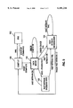
- FIG. 5 is a state diagram showing an example of the operation of the DSL modem illustrated in FIG. 3.
- a DSL communication system 50 includes a copper twisted pair subscriber line 52, a customer or residential DSL modem 54, a central office DSL modem 56, and a band splitter 58.
- Subscriber line 52 is a local loop, such as, a twisted pair of American wire gauge (AWG) 24 or 26 copper wires, which connects a central office 60 and a residence 62.
- Residence 62 can also be an office, building, or other facility.
- central office 60 can be any facility associated with a provider of telephone services.
- DSL modem 56 is coupled to a data network 64.
- Splitter 58 has a signal input 66 coupled to subscriber line 52, a higher-frequency output 68 coupled to DSL modem 56, and a lower-frequency output 70 coupled to a telephone switch 72.
- Telephone switch 72 is coupled to a POTS network 74.
- DSL modem 56, splitter 58, and telephone switch 72 are preferably located in central office 60.
- splitter 58 could be included as part of DSL modem 56 (e.g., DSL modem 56 is provided as an in-line device between subscriber line 52 and switch 72).
- one or more telephones 80, analog facsimile machine 81, and analog modem 82 can be coupled directly to subscriber line 52 as is well known in the art.
- Telephones 80 can be any conventional communication devices, including answering machines, which can be coupled to subscriber line 52 for providing various POTS functions.
- DSL modem 54 is coupled directly to subscriber line 52 at a data terminal, input/output or subscriber line access 55. DSL modem 54 is also coupled to a computer 84. Alternatively, DSL modem 54 could be coupled to other devices (not shown), such as, a network, server, or other communication or computing device.
- DSL modem 54 does not utilize a splitter between modem 54 and subscriber line 52 and between telephones 80 and subscriber line 52.
- DSL modem 54 advantageously utilizes digital signal processing techniques to adapt to varying subscriber line characteristics due to analog equipment, such as, telephones 80, machine 81, and modem 82, thereby eliminating the need for a splitter in residence 62.
- DSL modem 54 can operate concurrently with any of telephones 80, machine 81, and analog modem 82.
- DSL modem 54 preferably includes subscriber line access 55 which is part of a standard connector, such as, an RJ11 walljack, and is coupled to subscriber line 52 similarly to conventional telephones 80 and analog modems 82.
- Access 55 is preferably a two-wire terminal.
- Modem 54 can be provided as an internal device in computer 84, such as, on a PCI card, or as an external device.
- modem 54 is an internal device so that high speed communications between modem 54 and computer 84 are not slowed by serial ports associated with computer 84.
- modem 54 could be coupled through a printer port or a universal serial bus (USB) to computer 84.
- USB universal serial bus
- modem 54 is coupled to computer 84 via a data terminal 59.
- Modem 54 is preferably implemented with a digital signal processing chip set. Other suitable processors can be utilized to run software modules to implement the operations described in the present application.
- the software modules implement most tasks associated with modem 54. The tasks include digital filtering, line characterization, modulation, demodulation, gain control, equalization, initialization error correction, test functions, and other modem requirements.
- modem 54 adjusts operating characteristics, such as, equalization parameters, gain, and data rates, according to variables associated with line 52.
- Modem 54 is capable of receiving data at least at a one megabit per second (Mbps) data rate when line 52 is approximately 12 kilofeet and when all of telephones 80 are on-hook.
- the reception (downstream) data rate is no worse than 256 Kbps data rate in the presence of POTS-related impairments associated with telephones 80.
- Modem 54 is capable of transmitting data at least at a 100 Kbps data rate when line 52 has a length of 12 kilofeet and when all telephones 80 are on-hook.
- the transmission (upstream) data rate is preferably no worse than 64 Kbps in the presence of POTS-related impairments.
- DSL modem 56 is similar to DSL modem 54. However, modem 56 preferably is a lower-power modem to minimize the power consumed by central office 60. Additionally, modem 56 can have a sleep mode so that when modem 56 is not being accessed, significant power is not consumed by modem 56. Modem 56 can have a lower-cost receiver unit (not shown) because upstream data rates are lower than downstream data rates, as discussed above. In the sleep mode, processors and other electronic devices in modem 56 are placed in a low-power or no-power mode by slowing or stopping clock signals within modem 56. If modem 54 is utilized within a laptop computer, lower-power techniques are desirable for modem 54 as well.
- Modem 54 advantageously utilizes digital signal processing techniques to characterize and to classify interference sources going both to the POTS portion of the spectrum from the DSL portion of the spectrum and from the POTS portion of the spectrum to the DSL portion of the spectrum.
- Modem 54 compensates for these interference sources with digital signal processing techniques. For example, when telephone 80 is brought off-hook, an impedance change occurs on line 52. Modem 54 can adjust data rates, gain characteristics, and filter parameters to compensate for the impedance change.
- modem 54 can utilize digital signal processing techniques to compensate for interference from POTS equipment, such as, telephone 80.
- the digital signal processing techniques can rapidly adjust to interference sources so communication latency are not noticeable to the user.
- DSL modems 54 and 56 communicate signals as quadrature amplitude modulated (QAM) signals.
- DSL modems 54 and 56 communicate data at various constellation sizes, ranging from 4 to 256 UC points.
- N and K can be utilized to optimize data and frame rates.
- DSL modem 54 transmits upstream signals in a lower-frequency range and receives downstream signals in a higher-frequency range, in accordance with frequency division multiplexing techniques.
- modem 54 preferably transmits upstream signals at a carrier frequency between a lower band edge of 46 kHz and an upper band edge of 114 kHz.
- Modem 54 transmits upstream signals at a line rate (e.g., bandwidth or data rate) of 136 Kbps for a constellation size of 4 points and at a data rate of 340 Kbps for a constellation size of 32 points.
- Modem 56 receives the upstream signals at the same rates.
- DSL modem 56 transmits downstream signals at a carrier frequency between a lower band edge of 265.5 kHz and an upper band edge of 605.5 kHz. DSL modem 56 transmits downstream signals at data rate of 680 Kbps for a constellation size of 4 points and at a data rate of 1.7 Mbps for a constellation rate of 32 points. Modem 54 receives the downstream signals at the same rates.
- carrier frequencies can be utilized, such as, 342 kHz, 367.5 kHz, or 418.5 kHz for transmitting downstream information.
- the use of frequency division multiplexing eliminates the need for an echo canceler (not shown) and eliminates nonlinear effects of echo canceling.
- Modems 54 and 56 can utilize a variety of protocols to transmit and receive upstream and downstream signals. Modems 54 and 56 could additionally utilize a auxiliary channel within a control frequency band for transmitting control information between modems 54 and 56. Modems 54 and 56 can also utilize various error protocol, such as, Read-Solomon coding, multidimensional trellis coding, or other protocols, to gain higher immunity to noise and other phone line impairments.
- Trellis coding is a method of forward error correction where each signal element is assigned a coded binary value representing the element's phase and amplitude. The coding allows the receiving modem to determine, based on the value of the receiving signal, whether or not a given signal element is received in error.
- modem 54 includes a high-pass filter 57 coupled between access 55 which is coupled to subscriber line 52 and a control circuit 92.
- High-pass filter 57 preferably has a threshold frequency above 4 kHz and beneath the lowest band carrier edge for the DSL signals (e.g., 46 kHz) to prevent POTS signal from entering modem 54.
- Control circuit 92 includes a rapid retrain module or circuit 94, an error processor 96, a line characterization module or circuit 104, and an equalizer 98.
- an automatic gain control circuit (AGC) 102 is disposed between high-pass filter 57 and equalizer 98.
- AGC automatic gain control circuit
- Circuit 102 can be an analog circuit. Alternatively, circuit 102 can be a digital circuit located in control circuit 92 or a hybrid analog and digital circuit. Filter 57 can be a passive filter with a threshold frequency of 10 kHz. Equalizer 98 is a digital filter through which signals are transmitted and received to and from line 52. Equalizer 98 can be on a receive side of control circuit 92, a transmit side of control circuit 92, or both. Equalizer 98 is an adaptive compensation circuit for counteracting distortions on line 52.
- Equalizer 98 is preferably a decision feedback equalizer defined by tap coefficients. Equalizer 98 is implemented by a digital signal processor (not shown) running a software program. In the receive mode, equalizer 98 provides filtered signals to error processor 96 as well as other portions of control circuit 92. The filtered signals are processed by circuit 92 and provided at data terminal 59. In the transmit mode, other filters or equalizers can filter or pre-emphasize signals provided by modem 54 to line 52.
- Equalizer 98 must be converged (e.g., tuned) so the constellation associated with QAM signals are appropriately situated for decoding.
- equalizer 98 can be any device, digital or analog, for reducing frequency or phase distortion, or both, on subscriber line 52 by the introduction of filtering to compensate for the difference in attenuation or time delay, or both, at various frequencies in the transmission and reception spectrums.
- Rapid retrain circuit 94 provides control signals (e.g., tap coefficients) to equalizer 98 to converge equalizer 98, thereby compensating for distortion on line 52.
- Rapid retrain circuit 94 causes equalizer 98 to converge in response to a raise rate rapid retrain signal provided by error processor 96 on a line 97.
- Rapid retrain circuit 94 also causes equalizer 98 to converge in response to a lower rate rapid retrain signal provided by error processor on a line 95.
- Rapid retrain circuit 94 can utilize tap coefficients developed by line characterization circuit 104. As discussed in more detail below, circuit 104 can store a number of coefficients for known error conditions in a flash memory or other storage device. Alternately, the coefficients can be interactively determined, as discussed below.
- Error processor 96 monitors signals from equalizer 98 to determine if significant errors in the communication of data on line 52 are occurring. If significant errors are occurring, a lower rate rapid retrain signal is provided on line 95 so rapid retrain circuit 94 retrains modem 54. If few errors are occurring, and data is communicated at a lower data rate, a raise rate retrain signal is provided on line 97 so circuit 94 retrains modem 54 so data is communicated at a higher rate.
- modem 54 performs a variety of tasks to ensure accurate data communication.
- a retrain operation for modem 54 can include the following tasks: reacquiring timing from a remote modem, such as, modem 56, converging equalizer 98, and adjusting the data rate. Additionally, the retrain operation can also include characterizing line 52 and adjusting the automatic gain control circuit 102. Depending on modem 54 and line 52 parameters, circuit 94 can perform different levels of retrain operations.
- a retrain operation from initiation variables (e.g., scratch) of modem 54 can include reacquiring timing, characterizing line 52, adjusting circuit 102 from initialization variables, converging equalizer 98 from initialization variables, and determining a data rate.
- Characterizing line 52 can involve performing line characterization routines by circuit 104, as discussed below. Since adjustments to circuit 102 and converging equalizer 98 is an interactive process, these procedures can be time-consuming. The slow retrain can take as long 6.5 seconds. Nonetheless, time is saved, even in the slow retrain operation when compared to conventional modems, because modem 54 advantageously does not utilize an echo canceler (not shown). The echo canceler typically must be reset during a retrain operation.
- a rapid-retrain operation can eliminate one or more of the above steps or perform the above steps from predicted variables (variables which are initially closer to the desired value than initialization variables).
- the line characterization step is eliminated, and circuit 102 and 98 are adjusted slightly or converged from a stored coefficient.
- the center tap coefficient for equalizer 98 can be determined, and the remaining coefficients can be adjusted based on the difference between the determined center tap coefficient and the previous center tap coefficient.
- prestored tap coefficients are utilized so equalizer 98 does not have to be significantly converged.
- the tap coefficients are chosen based upon conditions recognized by circuit 94, such as, telephone 80 (FIG. 2) being brought off-hook.
- the adjustment of the gain circuit 102 can be restricted to a range to save time.
- System and application parameters associated with modem 54 and line 52 can define the amount of time required for a rapid retrain of modem 54.
- a rapid retrain may occur in a particular amount of real time, such as, less than 0.5 seconds.
- a rapid retrain within 0.5 seconds assures that the transmission of data is not affected for perceivable delays as modem 54 is retrained.
- a 0.5 second retrain operation is a vast improvement over the conventional 6.5 seconds for initialization retrain operations.
- the rapid retrain operation may occur in a much shorter time period, particularly if error processor 96 and rapid retrain circuit 94 are able to determine what changes on subscriber line 52 have caused errors.
- Circuit 94 can react to those changes and access a database or other data indicative of coefficients for equalizer 98, gain parameters for circuit 102, data rates, or other criteria for appropriate communication of data on line 52.
- a database could be stored on computer 84 coupled to modem 54 (FIG. 2).
- modem 54 FIG. 2
- rapid retrain circuit 94 is capable of retraining modem 54 in a rapid manner in response to error processor 96 discovering that there are errors in the communication of data on subscriber line 52.
- rapid retrain circuit 94 When rapid retrain circuit 94 performs a retrain operation, data rates associated with modem 54 are adjusted to maximize the data rate, while maintaining the integrity of the communications. For instance, if error processor 96 determines that a particular number of errors are occurring, rapid retrain circuit 94 may adjust the data rate down by reducing the size of the constellation or reducing the symbol rate. Error processor 96 can determine errors which require an adjustment of equalizer 98, such as, tangential error, radial error, or other errors. Error processor 96 can also react to trellis-coding errors, Reed-Solomon errors, mean squared error levels, or other errors.
- rapid retrain circuit 94 can retrain modem 54 and adjust the data rate upward by increasing the size of the constellation or increasing the symbol rate.
- the threshold used to compare the mean squared error, as well as other errors, is variable according to user parameters and the data rate.
- Line characterization circuit 104 can perform a variety of operations to characterize line 52 for the development of tap coefficients for equalizer 98 and of other parameters for modem 54.
- Line characterization tests can be performed when modem 54 is at initialization, in an idle mode, or in a non-idle mode.
- tones or test patterns are transmitted across line 52 in accordance with a test protocol.
- Modems 54 and 56 cooperate to determine characteristics of line 52 based upon received tones or test patterns.
- the test pattern can be sent and analyzed during the time the user is awaiting communications from the Internet. Further, a separate control channel can be utilized to send control information necessary to characterize line 52.
- circuit 104 can enter a learn mode and analyze line 52 under a variety of conditions. While in the learn mode, the user can bring telephone 80 (FIG. 2) off-hook in response to instructions generated by software on computer 84. Modem 54 can characterize line 52 during those particular conditions. Coefficients for equalizer 98 can be generated for those conditions and stored for a rapid retrain operation. Further still, circuit 104 can perform line-probing operations similar to the V.34 standard.
- an echo canceler (not shown) can be utilized on a transmit side of modem 54 to remove the transmitted signals in the transmit frequency spectrum.
- Control circuit 92 can analyze the characteristics in the transmit frequency spectrum of line 52. This analysis can be performed during non-idle modes. The portion of equalizer 98 on the transmit side can be adjusted according to the analysis to predistort or to preemphasize the transmitted signals.
- Digital frequency processing techniques can also include various error signal analysis, correction, and manipulation to determine when a rapid retrain is necessary as-well as techniques for rapidly converging an equalizer associated with modem 54.
- error processor 96 includes a Reed-Solomon decoder 120, a mean-squared error calculator 122, and a Trellis decoder 124.
- Reed-Solomon decoder 120 analyzes frames of data provided from error decoder 124 and determines if a frame error occurs and if errors are occurring in the frame.
- Reed-Solomon decoder 120 can correct errors as is well known in the art.
- calculator 122 can be replaced by other systems which can provide an indication of signal-to-noise ratios.
- Reed-Solomon decoder 120, calculator 122, and Trellis decoder 124 provide a lower rapid retrain signal when error conditions indicate that the data rate should be lowered.
- Rapid retrain circuit 94 performs a rapid retrain operation and lowers the data rate in response to the lower rate rapid retrain signal at input 95.
- the mean squared error calculator 122 provides a raise rate rapid retrain signal at input 97
- rapid retrain circuit 94 raises the data rate and performs a rapid retrain.
- modem 54 automatically raises or lowers its data rate to maintain high-speed and accurate communications in the presence of POTS-related impairments.
- modems 54 and 56 are somewhat lower than maximum data rates associated with conventional ADSL systems, these data rates are still significantly larger than conventional analog modem capabilities.
- the lower data rates allow modems 54 and 56 to use smaller constellation sizes and frequency division multiplexing, as well as withstand POTS-related impairments.
- Digital signal processing techniques can include rapid retrain operations where the modem is adjusted to changing subscriber line techniques due to POTS operations. Such adjustments can include adjusting automatic gain control circuit 102, converging equalizer 98, and error processing. Further, digital signal processing techniques can include line characterization techniques performed by circuit 104 (FIG. 3).
- FIG. 5 is a state diagram showing rapid retrain operations for modem 54.
- Modem 54 preferably always provides the highest data rate available on line 52, according to a rate-adaptive digital subscriber line technique.
- Modem 56 should have the ability to set a maximum downstream data rate so that the telephone company can limit the maximum downstream data rate to avoid advantaging subscribers who live close to office 60. According to this technique, modems 54 and 56 constantly adjust the data rates to reach maximum data rate potential on subscriber line 52 (FIG. 2).
- modem 54 (FIG. 2) is capable of a start-up state 100, an idle state 102, a data mode state 104, a fast retrain reduce rate state 106, and a fast retrain increase rate state 108.
- modem 54 transfers from idle state 102 to start-up state 100 when it receives a start-up command.
- modem 54 is initialized. During initialization, timing is acquired from a remote modem, such as, modem 56, automatic gain circuit 102 is adjusted, equalizer 98 is converged, the carrier phase is locked, line 52 is characterized, and a data rate is selected. If start-up is successfully completed, modem 54 advances to data mode state 104, where data is communicated across subscriber line 52.
- a remote modem such as, modem 56
- automatic gain circuit 102 is adjusted
- equalizer 98 is converged
- the carrier phase is locked
- line 52 is characterized, and a data rate is selected.
- modem 54 advances to data mode state 104, where data is communicated across subscriber line 52.
- error signals from error processor 92 are consistently checked. If the error signals are within an acceptable level, modem 54 is maintained in data mode state 104. However, if the error signals are above a particular level, modem 54 enters fast retrain reduce rate state 106. In state 106, modem 54 reduces the data rate, adjusts automatic control circuit 102, re-acquires timing, and converges equalizer 98. Preferably, equalizer 98 is retrained from stored coefficient values to reduce the amount of time required for retraining. Alternatively, another mode (not shown) may be entered where just the automatic gain control 102 (FIG. 3) is adjusted, and the data rate is not changed to compensate for errors.
- FOG. 3 automatic gain control 102
- state 106 if the fast retrain fails, another fast retrain is attempted. If more than two fast retrain attempts fail, modem 54 returns to start-up state 104. As at initialization, if start-up fails, modem 54 enters idle state 102.
- modem 54 If the fast retrain operation is successfully completed, modem 54 returns to data mode state 104 and continues to communicate data at a lower data rate.
- the data rate can be adjusted incrementally or by other relationships. For example, if the errors are due to known POTS activity, particular data rates may be known to operate during that activity, and those data rates may be chosen.
- modem 54 In state 104, if the mean square error signal provided by mean square error calculator 122 is below a threshold, modem 54 enters fast retrain increase rate state 108. Modem 54 is retrained in state 108 similarly to state 106, except that the data rate is increased. If the fast-retrain operation is completed successfully, modem 54 changes from state 108 to state 104 and continues normal data communication operations at the faster rate. If the fast retrain operation fails in state 108, modem 54 enters state 106 and performs a fast retrain reduce rate operation.
Abstract
Description
Claims (29)
Priority Applications (9)
| Application Number | Priority Date | Filing Date | Title |
|---|---|---|---|
| US08/943,484 US6101216A (en) | 1997-10-03 | 1997-10-03 | Splitterless digital subscriber line communication system |
| US09/028,016 US6445733B1 (en) | 1997-10-03 | 1998-02-23 | Method of and apparatus for performing line characterization in a non-idle mode in a subscriber line communication system |
| US09/028,210 US6161203A (en) | 1997-10-03 | 1998-02-23 | Communication system utilizing Reed-Solomon code to achieve auto frame synchronization acquistion |
| US09/028,023 US6430219B1 (en) | 1997-10-03 | 1998-02-23 | Method of and apparatus for performing line characterization in a subscriber line communication system |
| US09/028,141 US6263077B1 (en) | 1997-10-03 | 1998-02-23 | Digital subscriber line modem utilizing echo cancellation to reduce near-end cross-talk noise |
| JP2000515365A JP2001519620A (en) | 1997-10-03 | 1998-06-18 | Digital subscriber line communication system without splitter |
| EP98931376A EP1020056B1 (en) | 1997-10-03 | 1998-06-18 | Splitterless digital subscriber line communication system |
| DE69827520T DE69827520T2 (en) | 1997-10-03 | 1998-06-18 | DIGITAL SIGNAL TRANSMITTER LINE WITHOUT SIGNAL DEVICES FOR COMMUNICATION SYSTEM |
| PCT/US1998/012735 WO1999018701A1 (en) | 1997-10-03 | 1998-06-18 | Splitterless digital subscriber line communication system |
Applications Claiming Priority (1)
| Application Number | Priority Date | Filing Date | Title |
|---|---|---|---|
| US08/943,484 US6101216A (en) | 1997-10-03 | 1997-10-03 | Splitterless digital subscriber line communication system |
Related Child Applications (3)
| Application Number | Title | Priority Date | Filing Date |
|---|---|---|---|
| US09/028,210 Continuation-In-Part US6161203A (en) | 1997-10-03 | 1998-02-23 | Communication system utilizing Reed-Solomon code to achieve auto frame synchronization acquistion |
| US09/028,141 Continuation-In-Part US6263077B1 (en) | 1997-10-03 | 1998-02-23 | Digital subscriber line modem utilizing echo cancellation to reduce near-end cross-talk noise |
| US09/028,023 Continuation-In-Part US6430219B1 (en) | 1997-10-03 | 1998-02-23 | Method of and apparatus for performing line characterization in a subscriber line communication system |
Publications (1)
| Publication Number | Publication Date |
|---|---|
| US6101216A true US6101216A (en) | 2000-08-08 |
Family
ID=25479745
Family Applications (4)
| Application Number | Title | Priority Date | Filing Date |
|---|---|---|---|
| US08/943,484 Expired - Lifetime US6101216A (en) | 1997-10-03 | 1997-10-03 | Splitterless digital subscriber line communication system |
| US09/028,023 Expired - Lifetime US6430219B1 (en) | 1997-10-03 | 1998-02-23 | Method of and apparatus for performing line characterization in a subscriber line communication system |
| US09/028,210 Expired - Lifetime US6161203A (en) | 1997-10-03 | 1998-02-23 | Communication system utilizing Reed-Solomon code to achieve auto frame synchronization acquistion |
| US09/028,141 Expired - Lifetime US6263077B1 (en) | 1997-10-03 | 1998-02-23 | Digital subscriber line modem utilizing echo cancellation to reduce near-end cross-talk noise |
Family Applications After (3)
| Application Number | Title | Priority Date | Filing Date |
|---|---|---|---|
| US09/028,023 Expired - Lifetime US6430219B1 (en) | 1997-10-03 | 1998-02-23 | Method of and apparatus for performing line characterization in a subscriber line communication system |
| US09/028,210 Expired - Lifetime US6161203A (en) | 1997-10-03 | 1998-02-23 | Communication system utilizing Reed-Solomon code to achieve auto frame synchronization acquistion |
| US09/028,141 Expired - Lifetime US6263077B1 (en) | 1997-10-03 | 1998-02-23 | Digital subscriber line modem utilizing echo cancellation to reduce near-end cross-talk noise |
Country Status (5)
| Country | Link |
|---|---|
| US (4) | US6101216A (en) |
| EP (1) | EP1020056B1 (en) |
| JP (1) | JP2001519620A (en) |
| DE (1) | DE69827520T2 (en) |
| WO (1) | WO1999018701A1 (en) |
Cited By (62)
| Publication number | Priority date | Publication date | Assignee | Title |
|---|---|---|---|---|
| US6236714B1 (en) * | 1999-07-07 | 2001-05-22 | Centillium Communications, Inc. | Transmit power control for DSL modems in splitterless environment |
| US6252900B1 (en) | 1997-06-30 | 2001-06-26 | Integrated Telecom Express, Inc. | Forward compatible and expandable high speed communications system and method of operation |
| US6266348B1 (en) * | 1997-10-10 | 2001-07-24 | Aware, Inc. | Splitterless multicarrier modem |
| US6324268B1 (en) * | 1999-03-01 | 2001-11-27 | Ericsson Inc. | Splitter-less digital subscriber loop modems with improved throughput and voice and data separation |
| US6345071B1 (en) * | 1998-07-24 | 2002-02-05 | Compaq Computer Corporation | Fast retrain based on communication profiles for a digital modem |
| US20020027927A1 (en) * | 1997-12-31 | 2002-03-07 | Farhad Barzegar | Circuit to provide backup telephone service for a multiple service access system using a twisted pair |
| US6356585B1 (en) * | 1998-09-29 | 2002-03-12 | Conexant Systems, Inc. | Power cutback in splitterless ADSL systems |
| WO2002028045A1 (en) * | 2000-09-29 | 2002-04-04 | Siemens Aktiengesellschaft | Modulation method for a multi-carrier process with pre-emphasis |
| US6373889B1 (en) * | 1998-05-27 | 2002-04-16 | 3Com Corporation | In-Band signal and detector for PCM modem exception processing |
| US6377683B1 (en) | 1998-05-29 | 2002-04-23 | 3Com Corporation | Low complexity frequency domain echo canceller for DMT transceivers |
| US6385203B2 (en) * | 1996-03-29 | 2002-05-07 | Cisco Technology, Inc. | Communication server apparatus and method |
| US6400759B1 (en) | 1997-06-30 | 2002-06-04 | Integrated Telecom Express, Inc. | Device driver for rate adaptable modem with forward compatible and expandable functionality |
| WO2002052830A2 (en) * | 2000-12-22 | 2002-07-04 | Tyco Electronics Corporation | Wiring panel to connect security system to dsl line using modem to separate voice from data |
| US6430219B1 (en) * | 1997-10-03 | 2002-08-06 | Conexant Systems, Inc. | Method of and apparatus for performing line characterization in a subscriber line communication system |
| US6430199B1 (en) * | 1998-03-27 | 2002-08-06 | Telcordia Technologies, Inc. | Method and system for distributing telephone and broadband services over the copper pairs within a service location |
| WO2002062003A1 (en) * | 2001-02-01 | 2002-08-08 | Motorola, Inc., A Corporation Of The State Of Delaware | Method and apparatus for adjusting an acknowledgement timer in a communication network |
| US6434123B1 (en) * | 1998-12-28 | 2002-08-13 | Ericsson Inc. | Apparatus and method for broadband data communication |
| US6445733B1 (en) * | 1997-10-03 | 2002-09-03 | Conexant Systems, Inc. | Method of and apparatus for performing line characterization in a non-idle mode in a subscriber line communication system |
| US6456650B1 (en) * | 1998-02-04 | 2002-09-24 | Texas Instruments Incorporated | Splitterless modem using harmonics reduction |
| US20020150100A1 (en) * | 2001-02-22 | 2002-10-17 | White Timothy Richard | Method and apparatus for adaptive frame fragmentation |
| US20030007509A1 (en) * | 1998-06-26 | 2003-01-09 | Aware, Inc. | Multicarrier communication with variable overhead rate |
| US6507585B1 (en) | 1998-05-27 | 2003-01-14 | 3Com Corporation | Multi-carrier LAN adapter device using frequency domain equalizer |
| US6522731B2 (en) * | 1998-04-24 | 2003-02-18 | Mitsubishi Denki Kabushiki Kaisha | Data communication apparatus |
| US20030055992A1 (en) * | 2001-08-09 | 2003-03-20 | Globespanvirata Incorporated | Method and system for providing remote land-line access to customer premises equipment |
| US6542465B1 (en) * | 1999-05-28 | 2003-04-01 | 3Com Corporation | Method for flow control in asymmetric digital subscriber line devices |
| US6563864B1 (en) * | 1998-02-04 | 2003-05-13 | Texas Instruments Incorporated | Residential power cutback for splitterless DSL operation |
| US6567464B2 (en) | 1998-07-24 | 2003-05-20 | Compaq Information Technologies Group, L.P. | Fast retrain based on communication profiles for a digital modem |
| US6603811B1 (en) | 1998-05-29 | 2003-08-05 | 3Com Corporation | Low complexity frequency domain equalizer having fast re-lock |
| US20030147526A1 (en) * | 2002-02-05 | 2003-08-07 | Texas Instruments Incorporated | Adaptive cancellation network system and method for digital subscriber line |
| WO2003065704A1 (en) * | 2002-01-28 | 2003-08-07 | Siemens Aktiengesellschaft | Device and method for avoiding retraining processes in integrated voice and xdsl data transmission |
| US20030147355A1 (en) * | 2002-02-05 | 2003-08-07 | Mujica Fernando A. | Switchable hybrid design for asymmetric digital subscriber line |
| US20030169806A1 (en) * | 2002-03-07 | 2003-09-11 | Warke Nirmal C. | Dynamic hybrid switching in a wireline modem |
| US6633628B1 (en) * | 2000-01-07 | 2003-10-14 | 3Com Corporation | Apparatus and method for selecting a supported signal path for a transceiver |
| US20030198288A1 (en) * | 1999-03-08 | 2003-10-23 | Youssef Abdelilah | Modems, methods, and computer program products for selecting an optimum data rate using error signals representing the difference between the output of an equalizer and the output of a slicer or detector |
| US6646994B1 (en) * | 1998-12-28 | 2003-11-11 | Globespanvirata, Inc. | System and method for controlling distortion in the POTS band in a dual POTS and discrete multi-tone communication system |
| US6678721B1 (en) * | 1998-11-18 | 2004-01-13 | Globespanvirata, Inc. | System and method for establishing a point-to-multipoint DSL network |
| US6697618B1 (en) * | 2000-04-19 | 2004-02-24 | Phonex Broadband Corporation | System and method for detecting failures in a wireless phone/modem jack to prevent telephone line seizures |
| US6704317B1 (en) | 1998-05-27 | 2004-03-09 | 3Com Corporation | Multi-carrier LAN modem server |
| US6711138B1 (en) * | 1999-09-30 | 2004-03-23 | Conexant Systems, Inc. | Digital subscriber line/home phoneline network router |
| US6728546B1 (en) * | 1999-03-23 | 2004-04-27 | Legerity, Inc. | Computer peripheral base station for a cordless telephone |
| US20040085987A1 (en) * | 1997-10-10 | 2004-05-06 | Aware, Inc. | Splitterless multicarrier modem |
| US6760368B1 (en) * | 1999-04-06 | 2004-07-06 | Fujitsu Limited | Fast retraining method, apparatus, and storage medium in an xDSL transceiver |
| US6760433B2 (en) | 2000-05-15 | 2004-07-06 | Centillium Communications, Inc. | Central office interface techniques for digital subscriber lines |
| US6765955B1 (en) * | 1999-10-29 | 2004-07-20 | International Business Machines Corporation | Methods, systems and computer program products establishing a communication configuration for a modem connection to compensate for echo noise |
| US6791993B2 (en) * | 1997-08-28 | 2004-09-14 | Broadcom Corporation | Virtual gateway system and method |
| US20040179541A1 (en) * | 2003-03-12 | 2004-09-16 | Godwin John P. | Adaptation of dial-up devices to broadband facilities |
| US6826265B1 (en) * | 2000-02-16 | 2004-11-30 | Paradyne Corporation | DSL-ready pots device and method |
| US6826278B2 (en) | 2000-05-15 | 2004-11-30 | Centillium Communications, Inc. | Central office interface techniques for digital subscriber lines |
| US6850618B1 (en) | 2000-05-15 | 2005-02-01 | Centillium Communications, Inc. | Central office interface techniques for digital subscriber lines |
| US6891887B1 (en) | 1998-05-27 | 2005-05-10 | 3Com Corporation | Multi-carrier LAN adapter device using interpolative equalizer |
| US20050254507A1 (en) * | 2004-05-11 | 2005-11-17 | Matsushita Electric Industrial Co., Ltd. | DSL modem apparatus and control method for DSL modem apparatus |
| US7006559B1 (en) * | 2001-02-26 | 2006-02-28 | Apple Computer, Inc. | Automatic switching between DSL and analog on a single RJ-11 DSL/analog combo modem |
| US7099349B1 (en) * | 1999-03-10 | 2006-08-29 | Qwest Communications International Inc. | xDSL-based communication system |
| US7194024B2 (en) | 2003-01-29 | 2007-03-20 | Texas Instruments Incorporated | Method for adaptive hybrid selection during ADSL modem training |
| US20080246550A1 (en) * | 2007-04-05 | 2008-10-09 | Biedka Thomas E | Selective envelope modulation enabling reduced current consumption |
| US20100329317A1 (en) * | 1999-03-12 | 2010-12-30 | Tzannes Marcos C | Method and multi-carrier transceiver with stored application profiles for supporting multiple applications |
| US20110064124A1 (en) * | 1999-03-12 | 2011-03-17 | Marcos Tzannes | Method for seamlessly changing power modes in an adsl system |
| US20120093172A1 (en) * | 1999-03-12 | 2012-04-19 | Daphimo Co.B.V., Llc | Method for synchronizing seamless rate adaptation |
| US10986164B2 (en) | 2004-01-13 | 2021-04-20 | May Patents Ltd. | Information device |
| US10999124B1 (en) * | 2014-12-05 | 2021-05-04 | Marvell Asia Pte, Ltd. | Rapid rate adaptation in NBASE-T ethernet |
| US11115151B1 (en) * | 2019-03-22 | 2021-09-07 | Marvell Asia Pte, Ltd. | Method and apparatus for fast retraining of ethernet transceivers based on trickling error |
| US11387855B2 (en) * | 2019-03-22 | 2022-07-12 | Marvell Asia Pte, Ltd. | Method and apparatus for efficient fast retraining of ethernet transceivers |
Families Citing this family (95)
| Publication number | Priority date | Publication date | Assignee | Title |
|---|---|---|---|---|
| US7835989B1 (en) | 1992-12-09 | 2010-11-16 | Discovery Communications, Inc. | Electronic book alternative delivery systems |
| US8073695B1 (en) | 1992-12-09 | 2011-12-06 | Adrea, LLC | Electronic book with voice emulation features |
| KR100295386B1 (en) | 1992-12-09 | 2001-09-22 | 마크 홀린저 | Set-top terminals for cable television delivery systems |
| US7168084B1 (en) | 1992-12-09 | 2007-01-23 | Sedna Patent Services, Llc | Method and apparatus for targeting virtual objects |
| US9286294B2 (en) | 1992-12-09 | 2016-03-15 | Comcast Ip Holdings I, Llc | Video and digital multimedia aggregator content suggestion engine |
| US7509270B1 (en) | 1992-12-09 | 2009-03-24 | Discovery Communications, Inc. | Electronic Book having electronic commerce features |
| US7849393B1 (en) | 1992-12-09 | 2010-12-07 | Discovery Communications, Inc. | Electronic book connection to world watch live |
| US8095949B1 (en) | 1993-12-02 | 2012-01-10 | Adrea, LLC | Electronic book with restricted access features |
| US9053640B1 (en) | 1993-12-02 | 2015-06-09 | Adrea, LLC | Interactive electronic book |
| US7861166B1 (en) | 1993-12-02 | 2010-12-28 | Discovery Patent Holding, Llc | Resizing document pages to fit available hardware screens |
| US7865567B1 (en) | 1993-12-02 | 2011-01-04 | Discovery Patent Holdings, Llc | Virtual on-demand electronic book |
| US6798735B1 (en) | 1996-06-12 | 2004-09-28 | Aware, Inc. | Adaptive allocation for variable bandwidth multicarrier communication |
| US6786420B1 (en) | 1997-07-15 | 2004-09-07 | Silverbrook Research Pty. Ltd. | Data distribution mechanism in the form of ink dots on cards |
| US6618117B2 (en) | 1997-07-12 | 2003-09-09 | Silverbrook Research Pty Ltd | Image sensing apparatus including a microcontroller |
| US6624848B1 (en) | 1997-07-15 | 2003-09-23 | Silverbrook Research Pty Ltd | Cascading image modification using multiple digital cameras incorporating image processing |
| US7551201B2 (en) | 1997-07-15 | 2009-06-23 | Silverbrook Research Pty Ltd | Image capture and processing device for a print on demand digital camera system |
| US7110024B1 (en) | 1997-07-15 | 2006-09-19 | Silverbrook Research Pty Ltd | Digital camera system having motion deblurring means |
| US6879341B1 (en) | 1997-07-15 | 2005-04-12 | Silverbrook Research Pty Ltd | Digital camera system containing a VLIW vector processor |
| US6690419B1 (en) | 1997-07-15 | 2004-02-10 | Silverbrook Research Pty Ltd | Utilising eye detection methods for image processing in a digital image camera |
| JP3436742B2 (en) * | 1997-10-10 | 2003-08-18 | アウェア, インコーポレイテッド | Splitterless multi-carrier modem |
| CA2318936C (en) * | 1997-12-10 | 2004-04-06 | Thomson Licensing S.A. | Method for protecting the audio/visual data across the nrss interface |
| US6873652B1 (en) * | 1998-04-01 | 2005-03-29 | Panasonic Communications Co., Ltd. | Activation of multiple xDSL modems with implicit channel probe |
| SE518730C2 (en) * | 1998-05-12 | 2002-11-12 | Ericsson Telefon Ab L M | Method and apparatus for securing an ADSL connection |
| US6477197B1 (en) * | 1998-06-30 | 2002-11-05 | Arris International, Inc. | Method and apparatus for a cable modem upstream RF switching system |
| AUPP702098A0 (en) | 1998-11-09 | 1998-12-03 | Silverbrook Research Pty Ltd | Image creation method and apparatus (ART73) |
| US6618385B1 (en) * | 1998-09-23 | 2003-09-09 | Cirrus Logic, Inc. | High performance, high bandwidth, and adaptive local area network communications |
| US6643788B1 (en) * | 1998-11-30 | 2003-11-04 | Raytheon Company | Method for detecting a number of consecutive valid data frames and advancing into a lock mode to monitor synchronization patterns within a synchronization window |
| US6389036B1 (en) * | 1998-12-17 | 2002-05-14 | Harris Breedband Wireless Access, Inc. | Airlink transport container |
| US6587502B1 (en) * | 1998-12-28 | 2003-07-01 | Globespanvirata, Inc. | System and method for profile selection during fast retrain of a wideband modem |
| US6711207B1 (en) * | 1999-03-11 | 2004-03-23 | Globespanvirata, Inc. | System and method for reduced power consumption in digital subscriber line modems |
| US6731726B1 (en) | 1999-04-12 | 2004-05-04 | Conexant Systems, Inc. | Communication on hold |
| USRE42661E1 (en) | 1999-04-12 | 2011-08-30 | V-Dot Technologies, Llc | Method and apparatus for fast V.90 modem startup |
| US6704399B1 (en) * | 1999-04-12 | 2004-03-09 | Conexant Systems, Inc. | Quick connect parameter exchange |
| US6819749B1 (en) * | 1999-04-12 | 2004-11-16 | Mindspeed Technologies, Inc. | Method and apparatus for fast V.90 modem startup |
| US6912276B1 (en) * | 1999-04-12 | 2005-06-28 | Silicon Laboratories, Inc. | Modem on hold |
| WO2000067419A1 (en) * | 1999-05-03 | 2000-11-09 | Teradyne, Inc. | Adsl test system |
| AUPQ056099A0 (en) * | 1999-05-25 | 1999-06-17 | Silverbrook Research Pty Ltd | A method and apparatus (pprint01) |
| US6748016B1 (en) | 1999-07-16 | 2004-06-08 | Aware, Inc. | System and method for transmitting messages between transceivers using electromagnetically coupled signals |
| AU5401499A (en) * | 1999-10-14 | 2001-04-26 | Alcatel | ADSL filter |
| US7215670B1 (en) * | 1999-11-22 | 2007-05-08 | Texas Instruments Incorporated | Hardware acceleration for reassembly of message packets in a universal serial bus peripheral device |
| US6804243B1 (en) * | 1999-11-22 | 2004-10-12 | Texas Instruments Incorporated | Hardware acceleration for segmentation of message packets in a universal serial bus peripheral device |
| US6760333B1 (en) * | 1999-11-22 | 2004-07-06 | Texas Instruments Incorporated | Hybrid digital subscriber loop and voice-band universal serial bus modem |
| EP2270996B1 (en) | 2000-01-07 | 2018-03-07 | TQ Delta, LLC | Systems and methods for characterizing transmission lines in a multi-carrier dsl environment |
| DE10001150A1 (en) * | 2000-01-13 | 2001-07-19 | Siemens Ag | Transmission errors handling procedure esp. for ADSL-, and UDSL-, data transmission method e.g. with analog telephone and computer terminals - involves continual monitoring of data transmission for determining transmission errors, and measurement of bit-error rates for detecting any exceeding of threshold-amount prior to adaption procedure |
| US7103635B2 (en) * | 2000-01-28 | 2006-09-05 | Lucent Technologies Inc. | Really simple mail transport protocol |
| US6775355B1 (en) * | 2000-02-16 | 2004-08-10 | Paradyne Corporation | Line sharing multipoint POTS splitter masking noise |
| US7035380B1 (en) | 2000-02-16 | 2006-04-25 | Paradyne Corporation | Line sharing multipoint POTS splitter with intelligent termination |
| US6839383B1 (en) | 2000-03-10 | 2005-01-04 | Cisco Technology, Inc. | Method and system for testing a digital subscriber line modem |
| GB2362063A (en) * | 2000-04-25 | 2001-11-07 | Mitel Corp | Connecting broadband voice and data signals to telephone systems |
| US6963603B1 (en) | 2000-06-06 | 2005-11-08 | Ikanos Communication, Inc. | Method and apparatus for pre-compensation of an XDSL modem |
| US6836485B1 (en) * | 2000-12-22 | 2004-12-28 | Applied Micro Circuits Corporation | System and method for programming loss of synchronization in a multidimensional digital frame structure |
| US6597733B2 (en) | 2001-03-05 | 2003-07-22 | Ensemble Communications, Inc. | Equalizer performance enhancements for broadband wireless applications |
| DE10112816B4 (en) * | 2001-03-16 | 2005-12-29 | Siemens Ag | Method for rapid passive calibration of transceivers on their transmission medium |
| US7564895B2 (en) * | 2001-03-29 | 2009-07-21 | Nortel Networks Limited | Method and apparatus for monitoring channel frequency response |
| JP2002314702A (en) * | 2001-04-13 | 2002-10-25 | Fujitsu Ltd | xDSL MODEM |
| US7158563B2 (en) | 2001-06-01 | 2007-01-02 | The Board Of Trustees Of The Leland Stanford Junior University | Dynamic digital communication system control |
| US7577100B2 (en) * | 2001-07-27 | 2009-08-18 | Stephen Pollmann | System and method for measuring signal to noise values in an adaptive wireless communication system |
| US7793326B2 (en) | 2001-08-03 | 2010-09-07 | Comcast Ip Holdings I, Llc | Video and digital multimedia aggregator |
| US7908628B2 (en) | 2001-08-03 | 2011-03-15 | Comcast Ip Holdings I, Llc | Video and digital multimedia aggregator content coding and formatting |
| FR2830711B1 (en) | 2001-10-09 | 2005-09-23 | Thales Sa | METHOD AND DEVICE FOR AUTOMATIC SELECTION OF THE FLOW IN HIGH FREQUENCY TRANSMISSIONS |
| DE10153740B4 (en) * | 2001-10-31 | 2006-05-24 | Infineon Technologies Ag | Method and device for low-pass filtering |
| DE10154644C2 (en) * | 2001-11-07 | 2003-12-11 | Siemens Ag | Method and device for optimized ADSL data transmission |
| DE10154935A1 (en) * | 2001-11-08 | 2003-05-22 | Siemens Ag | Method and device for optimized xDSL data transmission |
| EP1318614A1 (en) * | 2001-12-05 | 2003-06-11 | General Instrument Corporation | Repeater for upstream and downstream signals |
| GB2383919B (en) * | 2002-01-04 | 2005-01-26 | Fujitsu Ltd | Line extender |
| AU2003250235A1 (en) * | 2002-06-03 | 2003-12-19 | Thomson Licensing S.A. | Dsl modem and method for establishing a data transfer mode therefore |
| WO2003105352A2 (en) * | 2002-06-07 | 2003-12-18 | Tokyo Electron Limited | A method and system for providing window shaping for multiline transmission in a communications system |
| KR100467587B1 (en) * | 2002-06-07 | 2005-01-24 | 삼성전자주식회사 | Method for self-diagnosing facsimile and the facsimile for performing the method |
| DE10226347C1 (en) * | 2002-06-13 | 2003-11-27 | Infineon Technologies Ag | Transmission path parameters determination method using echo pulse response with echo compensation for line beginning and/or line end echo |
| US6980824B2 (en) * | 2003-04-17 | 2005-12-27 | International Business Machines Corporation | Method and system for optimizing transmission and reception power levels in a communication system |
| CN1856987B (en) | 2003-08-21 | 2011-06-01 | 阿瓦雷公司 | Nonlinear device detection |
| JP3778192B2 (en) * | 2003-09-10 | 2006-05-24 | 日本電気株式会社 | Dynamic network automatic configuration server and system |
| US7570685B2 (en) * | 2003-10-06 | 2009-08-04 | Hiroshi Takatori | System, method and apparatus for crosstalk cancellation |
| US8077763B2 (en) * | 2003-10-21 | 2011-12-13 | Symbol Technologies, Inc. | Full-duplex radio frequency echo cancellation |
| US7239696B2 (en) * | 2003-12-15 | 2007-07-03 | International Business Machines Corporation | Automatic reset for DSL lines |
| JP4554262B2 (en) * | 2004-04-16 | 2010-09-29 | パナソニック株式会社 | Balanced transmission device |
| US7672294B2 (en) * | 2004-09-30 | 2010-03-02 | Alcatel-Lucent Usa Inc. | Methods and devices for achieving parallel operation between IP and analog phones |
| US7606322B2 (en) * | 2004-10-07 | 2009-10-20 | Microelectronics Technology Inc. | Digital pre-distortion technique using nonlinear filters |
| US7558213B2 (en) | 2005-06-15 | 2009-07-07 | AT&T Intellectual Property I, LLP | Methods and apparatus to determine digital subscriber line configuration parameters |
| US7848402B1 (en) * | 2005-09-29 | 2010-12-07 | Altera Corporation | Phase-adjusted pre-emphasis and equalization for data communication |
| US20070195905A1 (en) * | 2006-02-21 | 2007-08-23 | Adc Telecommunications, Inc. | Forward error correction in wideband digital RF transport systems |
| ATE403296T1 (en) * | 2006-06-09 | 2008-08-15 | Alcatel Lucent | APPLICATION RESYNCHRONIZATION DEVICE AND METHOD THEREOF |
| US20080181393A1 (en) * | 2007-01-26 | 2008-07-31 | Ronald Brost | Methods and apparatus to maintain communication services during a power failure |
| US7983373B2 (en) | 2007-02-07 | 2011-07-19 | Vintomie Networks B.V., Llc | Clock distribution for 10GBase-T analog front end |
| CA2692484C (en) * | 2007-07-02 | 2013-04-16 | Lg Electronics Inc. | Digital broadcasting system and data processing method |
| US8347160B2 (en) * | 2007-07-13 | 2013-01-01 | Rohm Co., Ltd. | Information communication terminal, radio communication apparatus and radio communication network system capable of performing communication corresponding to purpose |
| EP2250801B1 (en) | 2008-01-29 | 2017-03-15 | Broadcom Corporation | Method and system for detecting non-linear devices |
| ES2362759B1 (en) * | 2008-04-14 | 2012-06-06 | Fundacio Privada Centre Tecnologic De Telecomunicacions De Catalunya | PROCEDURE AND DEVICE OF DIGITAL COMMUNICATIONS FOR THE RECEIPT OF DATA USING QAM SYMBOLS. |
| CN101626433B (en) * | 2008-07-08 | 2013-08-28 | 鸿富锦精密工业(深圳)有限公司 | Device and method for testing modem interface |
| US9130655B2 (en) | 2009-11-30 | 2015-09-08 | Broadcom Corporation | Methods and systems for detecting metallic faults affecting communications links |
| JP5595526B2 (en) * | 2011-01-27 | 2014-09-24 | 三菱電機株式会社 | Communication interface device, air conditioner, communication control method, and program |
| RU2520352C2 (en) * | 2012-08-28 | 2014-06-20 | Открытое акционерное общество "Российская корпорация ракетно-космического приборостроения и информационных систем" (ОАО "Российские космические системы") | System for automatic control of operation of modem of small-size spacecraft with ground-based satellite communication system flight control centre |
| US9344192B1 (en) * | 2014-11-20 | 2016-05-17 | Integra Research And Development, Llc | Driver chip for minimizing transmission impairments and for boosting signal transmission rates |
| WO2016106714A1 (en) * | 2014-12-31 | 2016-07-07 | 华为技术有限公司 | Data transmission method, apparatus and system |
| DE102018205400A1 (en) * | 2018-04-10 | 2019-10-10 | Fraunhofer-Gesellschaft zur Förderung der angewandten Forschung e.V. | SPECTRAL ANALYSIS SYSTEM, MOBILE DEVICE WITH A SPECTRAL ANALYSIS SYSTEM, A METHOD FOR DETERMINING A CORRECTION FUNCTION FOR THE IMAGING CORRECTION OF A SPECTRUM RECEIVED BY A SPECTRAL ANALYSIS SYSTEM AND A COMPUTER PROGRAM |
Citations (34)
| Publication number | Priority date | Publication date | Assignee | Title |
|---|---|---|---|---|
| US4333175A (en) * | 1980-05-09 | 1982-06-01 | Lynch Communication Systems, Inc. | Telephone system using pulse code modulated subscriber lines |
| US4689783A (en) * | 1983-08-11 | 1987-08-25 | Compagnie Industrielle Des Telecommunications Cit-Alcatel | Digital satellite exchange |
| US4700340A (en) * | 1986-05-20 | 1987-10-13 | American Telephone And Telegraph Company, At&T Bell Laboratories | Method and apparatus for providing variable reliability in a telecommunication switching system |
| US4761779A (en) * | 1985-11-28 | 1988-08-02 | Fujitsu Limited | Subscriber's line switching control system |
| US4766594A (en) * | 1985-05-20 | 1988-08-23 | Fujitsu Limited | Digital network system having arrangement for testing digital subscriber line |
| US4799217A (en) * | 1986-08-20 | 1989-01-17 | American Telephone And Telegraph Company, At&T Bell Laboratories | Three time slot digital subscriber line termination |
| US4961186A (en) * | 1988-11-30 | 1990-10-02 | At&T Bell Laboratories | Communication channel reallocation |
| US5144625A (en) * | 1990-12-27 | 1992-09-01 | Adtran | Digital subscriber line termination with signalling |
| US5243593A (en) * | 1991-06-27 | 1993-09-07 | Alcatel Network Systems, Inc. | Method of activating tandem digital subscriber lines |
| US5297145A (en) * | 1991-06-14 | 1994-03-22 | U.S. Philips Corporation | Digital subscriber line circuit for connecting an ISDN subscriber to the trunk side of a digital exchange |
| US5367540A (en) * | 1992-01-16 | 1994-11-22 | Fujitsu Limited | Transversal filter for use in a digital subscriber line transmission interface |
| US5408260A (en) * | 1994-01-11 | 1995-04-18 | Northern Telecom Limited | Customer premises ADSL signal distribution arrangement |
| US5410343A (en) * | 1991-09-27 | 1995-04-25 | Bell Atlantic Network Services, Inc. | Video-on-demand services using public switched telephone network |
| US5442693A (en) * | 1993-12-22 | 1995-08-15 | At&T Bell Laboratories | Integrated operator console |
| US5461616A (en) * | 1993-09-01 | 1995-10-24 | Fujitsu Limited | Asymmetric digital subscriber line control system |
| US5479447A (en) * | 1993-05-03 | 1995-12-26 | The Board Of Trustees Of The Leland Stanford, Junior University | Method and apparatus for adaptive, variable bandwidth, high-speed data transmission of a multicarrier signal over digital subscriber lines |
| US5519731A (en) * | 1994-04-14 | 1996-05-21 | Amati Communications Corporation | ADSL compatible discrete multi-tone apparatus for mitigation of T1 noise |
| US5528281A (en) * | 1991-09-27 | 1996-06-18 | Bell Atlantic Network Services | Method and system for accessing multimedia data over public switched telephone network |
| US5534912A (en) * | 1994-04-26 | 1996-07-09 | Bell Atlantic Network Services, Inc. | Extended range video on demand distribution system |
| US5559858A (en) * | 1993-05-28 | 1996-09-24 | U S West Advanced Technologies, Inc. | Method and apparatus for delivering secured telephony service in a hydrid coaxial cable network |
| US5592540A (en) * | 1993-05-28 | 1997-01-07 | U S West Advanced Technologies, Inc. | Method and apparatus for selectively delivering telephony signals on a hybrid coaxial cable network |
| US5596604A (en) * | 1993-08-17 | 1997-01-21 | Amati Communications Corporation | Multicarrier modulation transmission system with variable delay |
| US5627501A (en) * | 1994-04-14 | 1997-05-06 | Alcatel N.V. | Signal coupler with automatic common line attenuation compensation |
| WO1997020396A2 (en) * | 1995-11-27 | 1997-06-05 | Analog Devices, Inc. | Pots splitter assembly with improved transhybrid loss for digital subscriber loop transmission |
| US5668857A (en) * | 1996-03-29 | 1997-09-16 | Netspeed, Inc. | Communication server apparatus and method |
| EP0820168A2 (en) * | 1996-07-19 | 1998-01-21 | Texas Instruments Incorporated | Multimode modem, and protocols therefor |
| WO1998027665A1 (en) * | 1996-12-17 | 1998-06-25 | Paradyne Corporation | Apparatus and method for communicating voice and data between a customer premises and a central office |
| US5805669A (en) * | 1996-12-30 | 1998-09-08 | Paradyne Corporation | Rate adaptaptive subscriber line ("RADSL") modem and method of operation |
| US5852630A (en) * | 1997-07-17 | 1998-12-22 | Globespan Semiconductor, Inc. | Method and apparatus for a RADSL transceiver warm start activation procedure with precoding |
| US5883941A (en) * | 1996-11-08 | 1999-03-16 | Godigital Telecommunications | HDSL and POTS carrier system |
| US5889856A (en) * | 1997-05-22 | 1999-03-30 | Centillium Technology Corp. | ADSL integrated line card with digital splitter and POTS CODEC without bulky analog splitter |
| US5909445A (en) * | 1996-08-19 | 1999-06-01 | Adtran, Inc. | Mechanism for transporting digital pots signals within framing structure of high bit rate digital local subscriber loop signals |
| US5910970A (en) * | 1996-05-09 | 1999-06-08 | Texas Instruments Incorporated | MDSL host interface requirement specification |
| US6014425A (en) * | 1997-02-26 | 2000-01-11 | Paradyne Corporation | Apparatus and method for qualifying telephones and other attached equipment for optimum DSL operation |
Family Cites Families (42)
| Publication number | Priority date | Publication date | Assignee | Title |
|---|---|---|---|---|
| US3988677A (en) | 1975-06-23 | 1976-10-26 | Nasa | Space communication system for compressed data with a concatenated Reed-Solomon-Viterbi coding channel |
| US4020461A (en) | 1975-11-18 | 1977-04-26 | Trw Inc. | Method of and apparatus for transmitting and receiving coded digital signals |
| US4574167A (en) | 1984-08-29 | 1986-03-04 | Tii Computer Systems, Inc. | Method and apparatus for configurable line testing |
| JPH0773240B2 (en) * | 1985-12-13 | 1995-08-02 | 日本電気株式会社 | Automatic retraining method |
| US5001729A (en) * | 1987-05-26 | 1991-03-19 | Hayes Microcomputer Products, Inc. | High speed half duplex modem with fast turnaround protocol |
| US5259000A (en) * | 1987-08-26 | 1993-11-02 | Hitachi, Ltd. | Modulator-demodulator apparatus and system |
| US5048054A (en) * | 1989-05-12 | 1991-09-10 | Codex Corporation | Line probing modem |
| US5319650A (en) * | 1989-06-13 | 1994-06-07 | Fujitsu Limited | Modulator-demodulator device capable of detecting an unsynchronized frame state |
| US5101216A (en) * | 1990-09-21 | 1992-03-31 | Eastman Kodak Company | Xeroprinting using a corona charge injection modifying material |
| JPH0754937B2 (en) * | 1990-09-28 | 1995-06-07 | 日本電気株式会社 | Transceiver |
| US5050205A (en) | 1990-10-25 | 1991-09-17 | Communication Devices, Inc. | Dial line monitor and control unit |
| US5132991A (en) | 1990-11-29 | 1992-07-21 | Siemens Aktiengesellschaft | Frame error detection system |
| US5297186A (en) * | 1991-07-29 | 1994-03-22 | Codex Corporation | Device and method for on-line adaptive selection of baud rate and carrier frequency |
| CA2116584C (en) * | 1991-08-30 | 1999-01-19 | Vijay R. Raman | Adaptive echo canceller for voice messaging system |
| IT1252125B (en) | 1991-10-23 | 1995-06-05 | Sgs Thomson Microelectronics | METHOD AND CIRCUIT DEVICE FOR MEASURING OPERATING PARAMETERS OF AN INTERFACE CIRCUIT AND A USER TELEPHONE LINE CONNECTED TO THEM IN OPERATING CONDITIONS |
| US5428646A (en) * | 1992-12-24 | 1995-06-27 | Motorola, Inc. | Device and method for frame synchronization in a multi-level trellis coding system |
| US5450468A (en) | 1993-04-29 | 1995-09-12 | At&T Corp. | Method of rapidly assessing damage to outside loop plant |
| JP2768621B2 (en) * | 1993-06-25 | 1998-06-25 | 沖電気工業株式会社 | Decoding apparatus for convolutional code transmitted in a distributed manner |
| US5400322A (en) * | 1993-08-20 | 1995-03-21 | Amati Communications Corp. | Updating of bit allocations in a multicarrier modulation transmission system |
| US5392334A (en) | 1993-08-25 | 1995-02-21 | Intel Corporation | Off-hook detection and soft line seizure for telephone line sharing in a computer system |
| WO1995015630A1 (en) | 1993-11-30 | 1995-06-08 | Integrated Network Corporation | Network interface unit remote test pattern generation |
| US5559792A (en) | 1994-04-20 | 1996-09-24 | Lucent Technologies Inc. | Sound modification for use in simultaneous voice and data communications |
| AU2451595A (en) * | 1994-05-17 | 1995-12-05 | British Telecommunications Public Limited Company | Customer line tester |
| US5627863A (en) * | 1994-07-15 | 1997-05-06 | Amati Communications Corporation | Frame synchronization in multicarrier transmission systems |
| US5719883A (en) * | 1994-09-21 | 1998-02-17 | Lucent Technologies Inc. | Adaptive ARQ/FEC technique for multitone transmission |
| US5610983A (en) * | 1994-09-30 | 1997-03-11 | Thomson Consumer Electronics, Inc. | Apparatus for detecting a synchronization component in a satellite transmission system receiver |
| US5648989A (en) | 1994-12-21 | 1997-07-15 | Paradyne Corporation | Linear prediction filter coefficient quantizer and filter set |
| US5682419A (en) * | 1995-01-26 | 1997-10-28 | Grube; Gary W. | Method and apparatus for providing infrastructure call support |
| US5617466A (en) | 1995-03-20 | 1997-04-01 | Harris Corporation | Mechanism for controllably enabling test set to assert off-hook condition on telephone line in dependence upon detection of prescribed voltage level and absence of data traffic |
| US5790594A (en) * | 1995-07-28 | 1998-08-04 | Motorola, Inc. | High speed modem and method for expedited timing recovery |
| JP3176277B2 (en) * | 1995-12-27 | 2001-06-11 | キヤノン株式会社 | Facsimile machine |
| US5699365A (en) * | 1996-03-27 | 1997-12-16 | Motorola, Inc. | Apparatus and method for adaptive forward error correction in data communications |
| US5999563A (en) * | 1996-05-09 | 1999-12-07 | Texas Instruments Incorporated | Rate negotiation for variable-rate digital subscriber line signaling |
| US5751796A (en) * | 1996-06-21 | 1998-05-12 | Paradyne Corporation | Rapid startup protocol for communication between a plurality of modems |
| US5751701A (en) * | 1996-07-19 | 1998-05-12 | Globespan Technologies, Inc. | Rate adaptive digital subscriber line ("RADSL") modem |
| US5757680A (en) | 1996-10-11 | 1998-05-26 | Lucent Technologies Inc. | Method and arrangement for configuring electronic device for multiple testing formats |
| JP3372791B2 (en) * | 1996-10-28 | 2003-02-04 | キヤノン株式会社 | Data communication device |
| US6134265A (en) * | 1996-12-31 | 2000-10-17 | Cirrus Logic, Inc. | Precoding coefficient training in a V.34 modem |
| US5914982A (en) * | 1997-06-13 | 1999-06-22 | Rockwell Semiconductor Systems, Inc. | Method and apparatus for training linear equalizers in a PCM modem |
| US6069899A (en) * | 1997-08-28 | 2000-05-30 | Broadcam Homenetworking, Inc. | Home area network system and method |
| US6101216A (en) * | 1997-10-03 | 2000-08-08 | Rockwell International Corporation | Splitterless digital subscriber line communication system |
| US6111936A (en) * | 1998-01-28 | 2000-08-29 | Paradyne Corporation | Method and apparatus for automatically detecting and measuring distortion in a DSL system |
-
1997
- 1997-10-03 US US08/943,484 patent/US6101216A/en not_active Expired - Lifetime
-
1998
- 1998-02-23 US US09/028,023 patent/US6430219B1/en not_active Expired - Lifetime
- 1998-02-23 US US09/028,210 patent/US6161203A/en not_active Expired - Lifetime
- 1998-02-23 US US09/028,141 patent/US6263077B1/en not_active Expired - Lifetime
- 1998-06-18 WO PCT/US1998/012735 patent/WO1999018701A1/en active IP Right Grant
- 1998-06-18 DE DE69827520T patent/DE69827520T2/en not_active Expired - Lifetime
- 1998-06-18 JP JP2000515365A patent/JP2001519620A/en active Pending
- 1998-06-18 EP EP98931376A patent/EP1020056B1/en not_active Expired - Lifetime
Patent Citations (35)
| Publication number | Priority date | Publication date | Assignee | Title |
|---|---|---|---|---|
| US4333175A (en) * | 1980-05-09 | 1982-06-01 | Lynch Communication Systems, Inc. | Telephone system using pulse code modulated subscriber lines |
| US4689783A (en) * | 1983-08-11 | 1987-08-25 | Compagnie Industrielle Des Telecommunications Cit-Alcatel | Digital satellite exchange |
| US4766594A (en) * | 1985-05-20 | 1988-08-23 | Fujitsu Limited | Digital network system having arrangement for testing digital subscriber line |
| US4761779A (en) * | 1985-11-28 | 1988-08-02 | Fujitsu Limited | Subscriber's line switching control system |
| US4700340A (en) * | 1986-05-20 | 1987-10-13 | American Telephone And Telegraph Company, At&T Bell Laboratories | Method and apparatus for providing variable reliability in a telecommunication switching system |
| US4799217A (en) * | 1986-08-20 | 1989-01-17 | American Telephone And Telegraph Company, At&T Bell Laboratories | Three time slot digital subscriber line termination |
| US4961186A (en) * | 1988-11-30 | 1990-10-02 | At&T Bell Laboratories | Communication channel reallocation |
| US5144625A (en) * | 1990-12-27 | 1992-09-01 | Adtran | Digital subscriber line termination with signalling |
| US5297145A (en) * | 1991-06-14 | 1994-03-22 | U.S. Philips Corporation | Digital subscriber line circuit for connecting an ISDN subscriber to the trunk side of a digital exchange |
| US5243593A (en) * | 1991-06-27 | 1993-09-07 | Alcatel Network Systems, Inc. | Method of activating tandem digital subscriber lines |
| US5625404A (en) * | 1991-09-27 | 1997-04-29 | Bell Atlantic Network Services | Method and system for accessing multimedia data over public switched telephone network |
| US5528281A (en) * | 1991-09-27 | 1996-06-18 | Bell Atlantic Network Services | Method and system for accessing multimedia data over public switched telephone network |
| US5410343A (en) * | 1991-09-27 | 1995-04-25 | Bell Atlantic Network Services, Inc. | Video-on-demand services using public switched telephone network |
| US5367540A (en) * | 1992-01-16 | 1994-11-22 | Fujitsu Limited | Transversal filter for use in a digital subscriber line transmission interface |
| US5479447A (en) * | 1993-05-03 | 1995-12-26 | The Board Of Trustees Of The Leland Stanford, Junior University | Method and apparatus for adaptive, variable bandwidth, high-speed data transmission of a multicarrier signal over digital subscriber lines |
| US5559858A (en) * | 1993-05-28 | 1996-09-24 | U S West Advanced Technologies, Inc. | Method and apparatus for delivering secured telephony service in a hydrid coaxial cable network |
| US5592540A (en) * | 1993-05-28 | 1997-01-07 | U S West Advanced Technologies, Inc. | Method and apparatus for selectively delivering telephony signals on a hybrid coaxial cable network |
| US5596604A (en) * | 1993-08-17 | 1997-01-21 | Amati Communications Corporation | Multicarrier modulation transmission system with variable delay |
| US5461616A (en) * | 1993-09-01 | 1995-10-24 | Fujitsu Limited | Asymmetric digital subscriber line control system |
| US5442693A (en) * | 1993-12-22 | 1995-08-15 | At&T Bell Laboratories | Integrated operator console |
| US5408260A (en) * | 1994-01-11 | 1995-04-18 | Northern Telecom Limited | Customer premises ADSL signal distribution arrangement |
| US5519731A (en) * | 1994-04-14 | 1996-05-21 | Amati Communications Corporation | ADSL compatible discrete multi-tone apparatus for mitigation of T1 noise |
| US5627501A (en) * | 1994-04-14 | 1997-05-06 | Alcatel N.V. | Signal coupler with automatic common line attenuation compensation |
| US5534912A (en) * | 1994-04-26 | 1996-07-09 | Bell Atlantic Network Services, Inc. | Extended range video on demand distribution system |
| WO1997020396A2 (en) * | 1995-11-27 | 1997-06-05 | Analog Devices, Inc. | Pots splitter assembly with improved transhybrid loss for digital subscriber loop transmission |
| US5668857A (en) * | 1996-03-29 | 1997-09-16 | Netspeed, Inc. | Communication server apparatus and method |
| US5910970A (en) * | 1996-05-09 | 1999-06-08 | Texas Instruments Incorporated | MDSL host interface requirement specification |
| EP0820168A2 (en) * | 1996-07-19 | 1998-01-21 | Texas Instruments Incorporated | Multimode modem, and protocols therefor |
| US5909445A (en) * | 1996-08-19 | 1999-06-01 | Adtran, Inc. | Mechanism for transporting digital pots signals within framing structure of high bit rate digital local subscriber loop signals |
| US5883941A (en) * | 1996-11-08 | 1999-03-16 | Godigital Telecommunications | HDSL and POTS carrier system |
| WO1998027665A1 (en) * | 1996-12-17 | 1998-06-25 | Paradyne Corporation | Apparatus and method for communicating voice and data between a customer premises and a central office |
| US5805669A (en) * | 1996-12-30 | 1998-09-08 | Paradyne Corporation | Rate adaptaptive subscriber line ("RADSL") modem and method of operation |
| US6014425A (en) * | 1997-02-26 | 2000-01-11 | Paradyne Corporation | Apparatus and method for qualifying telephones and other attached equipment for optimum DSL operation |
| US5889856A (en) * | 1997-05-22 | 1999-03-30 | Centillium Technology Corp. | ADSL integrated line card with digital splitter and POTS CODEC without bulky analog splitter |
| US5852630A (en) * | 1997-07-17 | 1998-12-22 | Globespan Semiconductor, Inc. | Method and apparatus for a RADSL transceiver warm start activation procedure with precoding |
Cited By (97)
| Publication number | Priority date | Publication date | Assignee | Title |
|---|---|---|---|---|
| US6385203B2 (en) * | 1996-03-29 | 2002-05-07 | Cisco Technology, Inc. | Communication server apparatus and method |
| US6252900B1 (en) | 1997-06-30 | 2001-06-26 | Integrated Telecom Express, Inc. | Forward compatible and expandable high speed communications system and method of operation |
| US6400759B1 (en) | 1997-06-30 | 2002-06-04 | Integrated Telecom Express, Inc. | Device driver for rate adaptable modem with forward compatible and expandable functionality |
| US6791993B2 (en) * | 1997-08-28 | 2004-09-14 | Broadcom Corporation | Virtual gateway system and method |
| US6445733B1 (en) * | 1997-10-03 | 2002-09-03 | Conexant Systems, Inc. | Method of and apparatus for performing line characterization in a non-idle mode in a subscriber line communication system |
| US6430219B1 (en) * | 1997-10-03 | 2002-08-06 | Conexant Systems, Inc. | Method of and apparatus for performing line characterization in a subscriber line communication system |
| US6549520B1 (en) * | 1997-10-10 | 2003-04-15 | Aware, Inc. | Method and apparatus for varying power levels in a multicarrier modem |
| US20070248154A1 (en) * | 1997-10-10 | 2007-10-25 | Aware, Inc. | Splitterless multicarrier modem |
| US8400940B2 (en) | 1997-10-10 | 2013-03-19 | Daphimo Co., B.V., LLC | Splitterless multicarrier modem |
| US6266348B1 (en) * | 1997-10-10 | 2001-07-24 | Aware, Inc. | Splitterless multicarrier modem |
| US8717928B2 (en) | 1997-10-10 | 2014-05-06 | Intellectual Ventures Ii Llc | Splitterless multicarrier modem |
| US8031619B2 (en) | 1997-10-10 | 2011-10-04 | Daphimo Co., B.V., LLC | Splitterless multicarrier modem |
| US20040105465A1 (en) * | 1997-10-10 | 2004-06-03 | Aware, Inc. | Splitterless multicarrier modem |
| US20090323788A1 (en) * | 1997-10-10 | 2009-12-31 | Gross Richard W | Splitterless multicarrier modem |
| US20040085987A1 (en) * | 1997-10-10 | 2004-05-06 | Aware, Inc. | Splitterless multicarrier modem |
| US20020027927A1 (en) * | 1997-12-31 | 2002-03-07 | Farhad Barzegar | Circuit to provide backup telephone service for a multiple service access system using a twisted pair |
| US7394757B2 (en) | 1997-12-31 | 2008-07-01 | At&T Corp. | Circuit to provide backup telephone service for a multiple service access system using a twisted pair |
| US6868060B2 (en) | 1997-12-31 | 2005-03-15 | At&T Corp. | Circuit to provide backup telephone service for a multiple service access system using a twisted pair |
| US20050128941A1 (en) * | 1997-12-31 | 2005-06-16 | Farhad Barzegar | Circuit to provide backup telephone service for a multiple service access system using a twisted pair |
| US20020027876A1 (en) * | 1997-12-31 | 2002-03-07 | Farhad Barzegar | Circuit to provide backup telephone service for a multiple service access system using a twisted pair |
| US6456650B1 (en) * | 1998-02-04 | 2002-09-24 | Texas Instruments Incorporated | Splitterless modem using harmonics reduction |
| US6563864B1 (en) * | 1998-02-04 | 2003-05-13 | Texas Instruments Incorporated | Residential power cutback for splitterless DSL operation |
| US6430199B1 (en) * | 1998-03-27 | 2002-08-06 | Telcordia Technologies, Inc. | Method and system for distributing telephone and broadband services over the copper pairs within a service location |
| US6522731B2 (en) * | 1998-04-24 | 2003-02-18 | Mitsubishi Denki Kabushiki Kaisha | Data communication apparatus |
| US6507585B1 (en) | 1998-05-27 | 2003-01-14 | 3Com Corporation | Multi-carrier LAN adapter device using frequency domain equalizer |
| US6373889B1 (en) * | 1998-05-27 | 2002-04-16 | 3Com Corporation | In-Band signal and detector for PCM modem exception processing |
| US6891887B1 (en) | 1998-05-27 | 2005-05-10 | 3Com Corporation | Multi-carrier LAN adapter device using interpolative equalizer |
| US6704317B1 (en) | 1998-05-27 | 2004-03-09 | 3Com Corporation | Multi-carrier LAN modem server |
| US6377683B1 (en) | 1998-05-29 | 2002-04-23 | 3Com Corporation | Low complexity frequency domain echo canceller for DMT transceivers |
| US6603811B1 (en) | 1998-05-29 | 2003-08-05 | 3Com Corporation | Low complexity frequency domain equalizer having fast re-lock |
| US20030007509A1 (en) * | 1998-06-26 | 2003-01-09 | Aware, Inc. | Multicarrier communication with variable overhead rate |
| US8718179B2 (en) | 1998-06-26 | 2014-05-06 | Intellectual Ventures Ii Llc | Multicarrier communication with variable overhead rate |
| US20060251123A1 (en) * | 1998-06-26 | 2006-11-09 | Aware, Inc. | Multicarrier communication with variable overhead rate |
| US6567464B2 (en) | 1998-07-24 | 2003-05-20 | Compaq Information Technologies Group, L.P. | Fast retrain based on communication profiles for a digital modem |
| US6345071B1 (en) * | 1998-07-24 | 2002-02-05 | Compaq Computer Corporation | Fast retrain based on communication profiles for a digital modem |
| US6356585B1 (en) * | 1998-09-29 | 2002-03-12 | Conexant Systems, Inc. | Power cutback in splitterless ADSL systems |
| US6678721B1 (en) * | 1998-11-18 | 2004-01-13 | Globespanvirata, Inc. | System and method for establishing a point-to-multipoint DSL network |
| US6434123B1 (en) * | 1998-12-28 | 2002-08-13 | Ericsson Inc. | Apparatus and method for broadband data communication |
| US6646994B1 (en) * | 1998-12-28 | 2003-11-11 | Globespanvirata, Inc. | System and method for controlling distortion in the POTS band in a dual POTS and discrete multi-tone communication system |
| US6324268B1 (en) * | 1999-03-01 | 2001-11-27 | Ericsson Inc. | Splitter-less digital subscriber loop modems with improved throughput and voice and data separation |
| US6665336B2 (en) * | 1999-03-08 | 2003-12-16 | International Business Machines Corporation | Modems, methods, and computer program products for selecting an optimum data rate using error signals representing the difference between the output of an equalizer and the output of a slicer or detector |
| US20030198288A1 (en) * | 1999-03-08 | 2003-10-23 | Youssef Abdelilah | Modems, methods, and computer program products for selecting an optimum data rate using error signals representing the difference between the output of an equalizer and the output of a slicer or detector |
| US7099349B1 (en) * | 1999-03-10 | 2006-08-29 | Qwest Communications International Inc. | xDSL-based communication system |
| US8340200B2 (en) | 1999-03-12 | 2012-12-25 | Daphimo Co. B.V., Llc | Method for seamlessly changing power modes in an ADSL system |
| US9369404B2 (en) | 1999-03-12 | 2016-06-14 | Intellectual Ventures Ii Llc | Method and multi-carrier transceiver with stored application profiles for supporting multiple applications |
| US8340162B2 (en) * | 1999-03-12 | 2012-12-25 | Daphimo Co. B.V., Llc | Method for synchronizing seamless rate adaptation |
| US20100329317A1 (en) * | 1999-03-12 | 2010-12-30 | Tzannes Marcos C | Method and multi-carrier transceiver with stored application profiles for supporting multiple applications |
| US20110064124A1 (en) * | 1999-03-12 | 2011-03-17 | Marcos Tzannes | Method for seamlessly changing power modes in an adsl system |
| US8351491B2 (en) | 1999-03-12 | 2013-01-08 | Daphimo Co. B.V., Llc | Method and multi-carrier transceiver with stored application profiles for supporting multiple applications |
| US20120093172A1 (en) * | 1999-03-12 | 2012-04-19 | Daphimo Co.B.V., Llc | Method for synchronizing seamless rate adaptation |
| US8934555B2 (en) | 1999-03-12 | 2015-01-13 | Intellectual Ventures Ii Llc | Method and multi-carrier transceiver with stored application profiles for supporting multiple applications |
| US8718163B2 (en) | 1999-03-12 | 2014-05-06 | Intellectual Ventures Ii Llc | Method for seamlessly changing power modes in an ADSL system |
| US6728546B1 (en) * | 1999-03-23 | 2004-04-27 | Legerity, Inc. | Computer peripheral base station for a cordless telephone |
| US6760368B1 (en) * | 1999-04-06 | 2004-07-06 | Fujitsu Limited | Fast retraining method, apparatus, and storage medium in an xDSL transceiver |
| US6542465B1 (en) * | 1999-05-28 | 2003-04-01 | 3Com Corporation | Method for flow control in asymmetric digital subscriber line devices |
| US6236714B1 (en) * | 1999-07-07 | 2001-05-22 | Centillium Communications, Inc. | Transmit power control for DSL modems in splitterless environment |
| US6711138B1 (en) * | 1999-09-30 | 2004-03-23 | Conexant Systems, Inc. | Digital subscriber line/home phoneline network router |
| US6765955B1 (en) * | 1999-10-29 | 2004-07-20 | International Business Machines Corporation | Methods, systems and computer program products establishing a communication configuration for a modem connection to compensate for echo noise |
| US6633628B1 (en) * | 2000-01-07 | 2003-10-14 | 3Com Corporation | Apparatus and method for selecting a supported signal path for a transceiver |
| US6826265B1 (en) * | 2000-02-16 | 2004-11-30 | Paradyne Corporation | DSL-ready pots device and method |
| US6697618B1 (en) * | 2000-04-19 | 2004-02-24 | Phonex Broadband Corporation | System and method for detecting failures in a wireless phone/modem jack to prevent telephone line seizures |
| US6850618B1 (en) | 2000-05-15 | 2005-02-01 | Centillium Communications, Inc. | Central office interface techniques for digital subscriber lines |
| US6826278B2 (en) | 2000-05-15 | 2004-11-30 | Centillium Communications, Inc. | Central office interface techniques for digital subscriber lines |
| US6760433B2 (en) | 2000-05-15 | 2004-07-06 | Centillium Communications, Inc. | Central office interface techniques for digital subscriber lines |
| WO2002028045A1 (en) * | 2000-09-29 | 2002-04-04 | Siemens Aktiengesellschaft | Modulation method for a multi-carrier process with pre-emphasis |
| WO2002052830A3 (en) * | 2000-12-22 | 2003-02-06 | Tyco Electronics Corp | Wiring panel to connect security system to dsl line using modem to separate voice from data |
| US7266841B2 (en) | 2000-12-22 | 2007-09-04 | Tyco Electronics Corporation | Security and communications module |
| WO2002052830A2 (en) * | 2000-12-22 | 2002-07-04 | Tyco Electronics Corporation | Wiring panel to connect security system to dsl line using modem to separate voice from data |
| CN100463478C (en) * | 2000-12-22 | 2009-02-18 | 泰科电子公司 | Wiring panel to connect security system to DSL line using modem to separate voice from data |
| US6747993B2 (en) | 2001-02-01 | 2004-06-08 | Motorola, Inc. | Method and apparatus for adjusting a communication timer in a communication network |
| WO2002062003A1 (en) * | 2001-02-01 | 2002-08-08 | Motorola, Inc., A Corporation Of The State Of Delaware | Method and apparatus for adjusting an acknowledgement timer in a communication network |
| US20020150100A1 (en) * | 2001-02-22 | 2002-10-17 | White Timothy Richard | Method and apparatus for adaptive frame fragmentation |
| US7616683B2 (en) | 2001-02-26 | 2009-11-10 | Apple Inc. | Automatic switching between DSL and analog on a single RJ-11 DSL/analog combo modem |
| US7006559B1 (en) * | 2001-02-26 | 2006-02-28 | Apple Computer, Inc. | Automatic switching between DSL and analog on a single RJ-11 DSL/analog combo modem |
| US20060146923A1 (en) * | 2001-02-26 | 2006-07-06 | Apple Computer, Inc. | Automatic switching between DSL and analog on a single RJ-11 DSL/analog combo modem |
| US20030055992A1 (en) * | 2001-08-09 | 2003-03-20 | Globespanvirata Incorporated | Method and system for providing remote land-line access to customer premises equipment |
| US20050078709A1 (en) * | 2002-01-28 | 2005-04-14 | Siemens Aktiengesellschaft | Device and method for avoiding retraining processes in integrated voice and xdsl data transmission |
| WO2003065704A1 (en) * | 2002-01-28 | 2003-08-07 | Siemens Aktiengesellschaft | Device and method for avoiding retraining processes in integrated voice and xdsl data transmission |
| US20030147355A1 (en) * | 2002-02-05 | 2003-08-07 | Mujica Fernando A. | Switchable hybrid design for asymmetric digital subscriber line |
| US7298838B2 (en) | 2002-02-05 | 2007-11-20 | Texas Instruments Incorporated | Adaptive cancellation network system and method for digital subscriber line |
| US20030147526A1 (en) * | 2002-02-05 | 2003-08-07 | Texas Instruments Incorporated | Adaptive cancellation network system and method for digital subscriber line |
| US7221754B2 (en) | 2002-02-05 | 2007-05-22 | Texas Instruments Incorporated | Switchable hybrid design for asymmetric digital subscriber line |
| US7260142B2 (en) | 2002-03-07 | 2007-08-21 | Texas Instruments Incorporated | Dynamic hybrid switching in a wireline modem |
| US20030169806A1 (en) * | 2002-03-07 | 2003-09-11 | Warke Nirmal C. | Dynamic hybrid switching in a wireline modem |
| US7194024B2 (en) | 2003-01-29 | 2007-03-20 | Texas Instruments Incorporated | Method for adaptive hybrid selection during ADSL modem training |
| US7525976B2 (en) | 2003-03-12 | 2009-04-28 | The Directv Group, Inc. | Adaptation of dial-up devices to broadband facilities |
| US20040179541A1 (en) * | 2003-03-12 | 2004-09-16 | Godwin John P. | Adaptation of dial-up devices to broadband facilities |
| US7860118B2 (en) | 2003-03-12 | 2010-12-28 | The Directv Group, Inc. | Adaptation of dial-up devices to broadband facilities |
| US20090180487A1 (en) * | 2003-03-12 | 2009-07-16 | The Directv Group, Inc. | Adaptation of dial-up devices to broadband facilities |
| US10986164B2 (en) | 2004-01-13 | 2021-04-20 | May Patents Ltd. | Information device |
| US20050254507A1 (en) * | 2004-05-11 | 2005-11-17 | Matsushita Electric Industrial Co., Ltd. | DSL modem apparatus and control method for DSL modem apparatus |
| US7688157B2 (en) * | 2007-04-05 | 2010-03-30 | Panasonic Corporation | Selective envelope modulation enabling reduced current consumption |
| US20080246550A1 (en) * | 2007-04-05 | 2008-10-09 | Biedka Thomas E | Selective envelope modulation enabling reduced current consumption |
| US10999124B1 (en) * | 2014-12-05 | 2021-05-04 | Marvell Asia Pte, Ltd. | Rapid rate adaptation in NBASE-T ethernet |
| US20210297307A1 (en) * | 2014-12-05 | 2021-09-23 | Marvell Asia Pte, Ltd. | Rapid rate adaptation in nbase-t ethernet |
| US11115151B1 (en) * | 2019-03-22 | 2021-09-07 | Marvell Asia Pte, Ltd. | Method and apparatus for fast retraining of ethernet transceivers based on trickling error |
| US11387855B2 (en) * | 2019-03-22 | 2022-07-12 | Marvell Asia Pte, Ltd. | Method and apparatus for efficient fast retraining of ethernet transceivers |
Also Published As
| Publication number | Publication date |
|---|---|
| JP2001519620A (en) | 2001-10-23 |
| DE69827520D1 (en) | 2004-12-16 |
| US6430219B1 (en) | 2002-08-06 |
| WO1999018701A1 (en) | 1999-04-15 |
| US6263077B1 (en) | 2001-07-17 |
| EP1020056A1 (en) | 2000-07-19 |
| EP1020056B1 (en) | 2004-11-10 |
| US6161203A (en) | 2000-12-12 |
| DE69827520T2 (en) | 2005-12-15 |
Similar Documents
| Publication | Publication Date | Title |
|---|---|---|
| US6101216A (en) | Splitterless digital subscriber line communication system | |
| US6445733B1 (en) | Method of and apparatus for performing line characterization in a non-idle mode in a subscriber line communication system | |
| US9130654B2 (en) | Performance customization system and process for optimizing xDSL performance | |
| US7991072B2 (en) | Multi-carrier modem transmitter with controlled transmit signal quality degradation for improving stability of operation | |
| US7295621B2 (en) | Communication start-up with variant spectral density mask | |
| EP1947831B1 (en) | Method, system and apparatus for adjusting the transmit power of the dsl transceiver | |
| US7142619B2 (en) | Long subscriber loops using automatic gain control mid-span extender unit | |
| US8363762B2 (en) | Digital subscriber line noise mitigation techniques, and applications thereof | |
| US20050190826A1 (en) | Digital subscriber line modem with bitloading using channel condition model | |
| US6356585B1 (en) | Power cutback in splitterless ADSL systems | |
| US7778346B2 (en) | Upstream power cutback | |
| WO2003055195A2 (en) | System and method for rate enhanced shdsl | |
| US20070071079A1 (en) | Selectable hybrid circuitry for transmission systems and method therefor | |
| EP1437871A1 (en) | System and method for reducing disruption in a DSL environment caused by a POTS transient event | |
| US7167548B1 (en) | Method and apparatus for modifying gain settings in a connection interface | |
| US6963641B1 (en) | Method and apparatus for providing variable attenuation to data signals in an XDSL frequency range | |
| US7864737B2 (en) | Method and device for transmitting data via a transmission link | |
| US20060146986A1 (en) | Method for training line drivers in a communication system | |
| KR100447391B1 (en) | method for automatically adjusting a receiving signal of the ADSL modem | |
| AU2007203099A1 (en) | Systems and methods for characterizing transmission lines using broadband signals in a multi-carrier DSL environment | |
| KR20030055567A (en) | method for controlling a handshaking of xDSL system |
Legal Events
| Date | Code | Title | Description |
|---|---|---|---|
| AS | Assignment |
Owner name: ROCKWELL INTERNATIONAL CORPORATION, CALIFORNIA Free format text: ASSIGNMENT OF ASSIGNORS INTEREST;ASSIGNORS:HENDERSON, P. MICHAEL;KO, KENNETH D.;ZURANSKI, EDWARD F.;AND OTHERS;REEL/FRAME:009077/0767;SIGNING DATES FROM 19970903 TO 19970909 |
|
| AS | Assignment |
Owner name: CREDIT SUISSE FIRST BOSTON, NEW YORK Free format text: SECURITY INTEREST;ASSIGNORS:CONEXANT SYSTEMS, INC.;BROOKTREE CORPORATION;BROOKTREE WORLDWIDE SALES CORPORATION;AND OTHERS;REEL/FRAME:009826/0056 Effective date: 19981221 |
|
| AS | Assignment |
Owner name: CONEXANT SYSTEMS, INC., CALIFORNIA Free format text: CHANGE OF NAME;ASSIGNOR:ROCKWELL SEMICONDUCTOR SYSTEMS, INC.;REEL/FRAME:010430/0648 Effective date: 19981014 |
|
| STCF | Information on status: patent grant |
Free format text: PATENTED CASE |
|
| AS | Assignment |
Owner name: CONEXANT SYSTEMS, INC., CALIFORNIA Free format text: RELEASE BY SECURED PARTY;ASSIGNOR:CREDIT SUISSE FIRST BOSTON;REEL/FRAME:012273/0217 Effective date: 20011018 Owner name: BROOKTREE WORLDWIDE SALES CORPORATION, CALIFORNIA Free format text: RELEASE BY SECURED PARTY;ASSIGNOR:CREDIT SUISSE FIRST BOSTON;REEL/FRAME:012273/0217 Effective date: 20011018 Owner name: BROOKTREE CORPORATION, CALIFORNIA Free format text: RELEASE BY SECURED PARTY;ASSIGNOR:CREDIT SUISSE FIRST BOSTON;REEL/FRAME:012273/0217 Effective date: 20011018 Owner name: CONEXANT SYSTEMS WORLDWIDE, INC., CALIFORNIA Free format text: RELEASE BY SECURED PARTY;ASSIGNOR:CREDIT SUISSE FIRST BOSTON;REEL/FRAME:012273/0217 Effective date: 20011018 |
|
| FEPP | Fee payment procedure |
Free format text: PAYOR NUMBER ASSIGNED (ORIGINAL EVENT CODE: ASPN); ENTITY STATUS OF PATENT OWNER: LARGE ENTITY |
|
| FPAY | Fee payment |
Year of fee payment: 4 |
|
| AS | Assignment |
Owner name: BANK OF NEW YORK TRUST COMPANY, N.A.,ILLINOIS Free format text: SECURITY AGREEMENT;ASSIGNOR:CONEXANT SYSTEMS, INC.;REEL/FRAME:018711/0818 Effective date: 20061113 Owner name: BANK OF NEW YORK TRUST COMPANY, N.A., ILLINOIS Free format text: SECURITY AGREEMENT;ASSIGNOR:CONEXANT SYSTEMS, INC.;REEL/FRAME:018711/0818 Effective date: 20061113 |
|
| FPAY | Fee payment |
Year of fee payment: 8 |
|
| AS | Assignment |
Owner name: CONEXANT SYSTEMS, INC., CALIFORNIA Free format text: RELEASE BY SECURED PARTY;ASSIGNOR:THE BANK OF NEW YORK MELLON TRUST COMPANY, N.A.;REEL/FRAME:023134/0249 Effective date: 20090821 Owner name: CONEXANT SYSTEMS, INC.,CALIFORNIA Free format text: RELEASE BY SECURED PARTY;ASSIGNOR:THE BANK OF NEW YORK MELLON TRUST COMPANY, N.A.;REEL/FRAME:023134/0249 Effective date: 20090821 |
|
| AS | Assignment |
Owner name: IKANOS COMMUNICATIONS, INC., CALIFORNIA Free format text: ASSIGNMENT OF ASSIGNORS INTEREST;ASSIGNORS:CONEXANT SYSTEMS, INC.;CONEXANT, INC.;BROOKTREE BROADBAND HOLDING INC.;REEL/FRAME:023163/0723 Effective date: 20090824 Owner name: IKANOS COMMUNICATIONS, INC.,CALIFORNIA Free format text: ASSIGNMENT OF ASSIGNORS INTEREST;ASSIGNORS:CONEXANT SYSTEMS, INC.;CONEXANT, INC.;BROOKTREE BROADBAND HOLDING INC.;REEL/FRAME:023163/0723 Effective date: 20090824 |
|
| FPAY | Fee payment |
Year of fee payment: 12 |
|
| AS | Assignment |
Owner name: ALCATEL-LUCENT USA, INC., NEW JERSEY Free format text: NOTICE OF GRANT OF SECURITY INTEREST IN PATENTS;ASSIGNOR:IKANOS COMMUNICATIONS, INC.;REEL/FRAME:035581/0710 Effective date: 20150430 |
|
| AS | Assignment |
Owner name: SILICON VALLEY BANK, CALIFORNIA Free format text: SECURITY INTEREST;ASSIGNOR:IKANOS COMMUNICATIONS, INC.;REEL/FRAME:035874/0351 Effective date: 20150602 |
|
| AS | Assignment |
Owner name: IKANOS COMMUNICATIONS, INC., CALIFORNIA Free format text: RELEASE BY SECURED PARTY;ASSIGNOR:ALCATEL-LUCENT USA, INC.;REEL/FRAME:036732/0876 Effective date: 20150929 Owner name: IKANOS COMMUNICATIONS, INC., CALIFORNIA Free format text: RELEASE BY SECURED PARTY;ASSIGNOR:SILICON VALLEY BANK;REEL/FRAME:036733/0031 Effective date: 20150930 |
|
| AS | Assignment |
Owner name: ROCKWELL SEMICONDUCTOR SYSTEMS, INC., CALIFORNIA Free format text: ASSIGNMENT OF ASSIGNORS INTEREST;ASSIGNORS:HENDERSON, P. MICHAEL;KO, KENNETH D.;ZURANSKI, EDWARD S.;AND OTHERS;SIGNING DATES FROM 19970903 TO 19970909;REEL/FRAME:036983/0807 |
|
| FEPP | Fee payment procedure |
Free format text: PAYOR NUMBER ASSIGNED (ORIGINAL EVENT CODE: ASPN); ENTITY STATUS OF PATENT OWNER: LARGE ENTITY Free format text: PAYER NUMBER DE-ASSIGNED (ORIGINAL EVENT CODE: RMPN); ENTITY STATUS OF PATENT OWNER: LARGE ENTITY |