US6003273A - Utilities infeed panel - Google Patents
Utilities infeed panel Download PDFInfo
- Publication number
- US6003273A US6003273A US09/087,562 US8756298A US6003273A US 6003273 A US6003273 A US 6003273A US 8756298 A US8756298 A US 8756298A US 6003273 A US6003273 A US 6003273A
- Authority
- US
- United States
- Prior art keywords
- panel
- infeed
- utilities
- ceiling
- opposite side
- Prior art date
- Legal status (The legal status is an assumption and is not a legal conclusion. Google has not performed a legal analysis and makes no representation as to the accuracy of the status listed.)
- Expired - Lifetime
Links
- 238000005192 partition Methods 0.000 claims abstract description 80
- 238000009434 installation Methods 0.000 claims description 9
- 230000006872 improvement Effects 0.000 claims description 4
- 238000005516 engineering process Methods 0.000 description 7
- 230000036961 partial effect Effects 0.000 description 6
- 230000008859 change Effects 0.000 description 4
- 239000007787 solid Substances 0.000 description 4
- 230000008901 benefit Effects 0.000 description 3
- 238000004891 communication Methods 0.000 description 3
- 238000013461 design Methods 0.000 description 3
- 238000007726 management method Methods 0.000 description 3
- 238000000034 method Methods 0.000 description 3
- 230000008569 process Effects 0.000 description 3
- 230000005540 biological transmission Effects 0.000 description 2
- 229910052602 gypsum Inorganic materials 0.000 description 2
- 239000010440 gypsum Substances 0.000 description 2
- 230000000873 masking effect Effects 0.000 description 2
- 238000012986 modification Methods 0.000 description 2
- 230000004048 modification Effects 0.000 description 2
- 229920000642 polymer Polymers 0.000 description 2
- 239000004677 Nylon Substances 0.000 description 1
- 230000004308 accommodation Effects 0.000 description 1
- 230000004888 barrier function Effects 0.000 description 1
- 230000009286 beneficial effect Effects 0.000 description 1
- 230000002860 competitive effect Effects 0.000 description 1
- 230000000295 complement effect Effects 0.000 description 1
- 230000001143 conditioned effect Effects 0.000 description 1
- 238000010276 construction Methods 0.000 description 1
- 230000006870 function Effects 0.000 description 1
- 230000036541 health Effects 0.000 description 1
- 238000003780 insertion Methods 0.000 description 1
- 230000037431 insertion Effects 0.000 description 1
- 230000010354 integration Effects 0.000 description 1
- 230000001788 irregular Effects 0.000 description 1
- 230000000670 limiting effect Effects 0.000 description 1
- 239000000463 material Substances 0.000 description 1
- 239000002184 metal Substances 0.000 description 1
- 229920001778 nylon Polymers 0.000 description 1
- 230000008520 organization Effects 0.000 description 1
- 238000012545 processing Methods 0.000 description 1
- 238000009418 renovation Methods 0.000 description 1
- 238000010079 rubber tapping Methods 0.000 description 1
- 238000000926 separation method Methods 0.000 description 1
- 238000000638 solvent extraction Methods 0.000 description 1
- 230000003068 static effect Effects 0.000 description 1
- 238000009423 ventilation Methods 0.000 description 1
- XLYOFNOQVPJJNP-UHFFFAOYSA-N water Substances O XLYOFNOQVPJJNP-UHFFFAOYSA-N 0.000 description 1
Images


Classifications
-
- E—FIXED CONSTRUCTIONS
- E04—BUILDING
- E04C—STRUCTURAL ELEMENTS; BUILDING MATERIALS
- E04C2/00—Building elements of relatively thin form for the construction of parts of buildings, e.g. sheet materials, slabs, or panels
- E04C2/44—Building elements of relatively thin form for the construction of parts of buildings, e.g. sheet materials, slabs, or panels characterised by the purpose
- E04C2/52—Building elements of relatively thin form for the construction of parts of buildings, e.g. sheet materials, slabs, or panels characterised by the purpose with special adaptations for auxiliary purposes, e.g. serving for locating conduits
- E04C2/521—Building elements of relatively thin form for the construction of parts of buildings, e.g. sheet materials, slabs, or panels characterised by the purpose with special adaptations for auxiliary purposes, e.g. serving for locating conduits serving for locating conduits; for ventilating, heating or cooling
-
- E—FIXED CONSTRUCTIONS
- E04—BUILDING
- E04B—GENERAL BUILDING CONSTRUCTIONS; WALLS, e.g. PARTITIONS; ROOFS; FLOORS; CEILINGS; INSULATION OR OTHER PROTECTION OF BUILDINGS
- E04B2/00—Walls, e.g. partitions, for buildings; Wall construction with regard to insulation; Connections specially adapted to walls
- E04B2/74—Removable non-load-bearing partitions; Partitions with a free upper edge
- E04B2/7407—Removable non-load-bearing partitions; Partitions with a free upper edge assembled using frames with infill panels or coverings only; made-up of panels and a support structure incorporating posts
- E04B2/7448—Removable non-load-bearing partitions; Partitions with a free upper edge assembled using frames with infill panels or coverings only; made-up of panels and a support structure incorporating posts with separate framed panels without intermediary posts, extending from floor to ceiling
-
- H—ELECTRICITY
- H02—GENERATION; CONVERSION OR DISTRIBUTION OF ELECTRIC POWER
- H02G—INSTALLATION OF ELECTRIC CABLES OR LINES, OR OF COMBINED OPTICAL AND ELECTRIC CABLES OR LINES
- H02G3/00—Installations of electric cables or lines or protective tubing therefor in or on buildings, equivalent structures or vehicles
- H02G3/28—Installations of cables, lines, or separate protective tubing therefor in conduits or ducts pre-established in walls, ceilings or floors
- H02G3/286—Installations of cables, lines, or separate protective tubing therefor in conduits or ducts pre-established in walls, ceilings or floors in walls
- H02G3/288—Installations of cables, lines, or separate protective tubing therefor in conduits or ducts pre-established in walls, ceilings or floors in walls in modular walls, e.g. wall panels
-
- E—FIXED CONSTRUCTIONS
- E04—BUILDING
- E04B—GENERAL BUILDING CONSTRUCTIONS; WALLS, e.g. PARTITIONS; ROOFS; FLOORS; CEILINGS; INSULATION OR OTHER PROTECTION OF BUILDINGS
- E04B2/00—Walls, e.g. partitions, for buildings; Wall construction with regard to insulation; Connections specially adapted to walls
- E04B2/74—Removable non-load-bearing partitions; Partitions with a free upper edge
- E04B2002/7488—Details of wiring
-
- E—FIXED CONSTRUCTIONS
- E04—BUILDING
- E04B—GENERAL BUILDING CONSTRUCTIONS; WALLS, e.g. PARTITIONS; ROOFS; FLOORS; CEILINGS; INSULATION OR OTHER PROTECTION OF BUILDINGS
- E04B2/00—Walls, e.g. partitions, for buildings; Wall construction with regard to insulation; Connections specially adapted to walls
- E04B2/74—Removable non-load-bearing partitions; Partitions with a free upper edge
- E04B2002/749—Partitions with screw-type jacks
- E04B2002/7492—Partitions with screw-type jacks used in partitions extending from floor to ceiling
Definitions
- the present invention relates to the finishing or fitting-out of building space and the like of the type having a generally open plan interior, and in particular to a utilities infeed panel that forms an integral portion of a prefabricated partition system and provides vertical routing of utilities within the utilities infeed panel through an opening in the ceiling.
- utilities encompass all types of resources that may be used to support or service a worker, such as communications and data used with computers and other types of data processors, telecommunications, electronic displays, etc., electrical power, conditioned water, and physical accommodations, such as lighting, HVAC, sprinklers, security, sound masking, and the like.
- Open office plans have been developed to reduce overall office costs, and generally incorporate large, open floor spaces in buildings that are equipped with modular furniture systems, which are readily reconfigurable to accommodate the ever-changing needs of a specific user, as well as the divergent requirements of different tenants.
- One arrangement commonly used for furniture open plans includes movable partial height partition panels that are detachably interconnected to partition off the open spaces into individual work settings and/or offices.
- Such partial height partition panels are configured to receive hang-on furniture units, such as worksurfaces, overhead cabinets, shelves, etc., and are generally known in the office furniture industry as "systems furniture.”
- Another arrangement for dividing and/or partitioning open plans involves the use of modular furniture, in which a plurality of differently shaped, complementary freestanding furniture units are positioned in a side-by-side relationship, with upstanding partial height privacy screens available to attach to selected furniture units to create individual, distinct work settings and/or offices. All of these types of modular furniture systems have been widely received due largely to their ability to be readily reconfigured and/or moved to a new site, since they are not part of a permanent leasehold improvement.
- the products must also be able to accommodate diverse organizations, unique design signatures, and constantly changing work processes. Workers also need effective lighting, better air quality, life safety, and ergonomic task support to promote productivity, minimize the expenses of absenteeism and workman's compensation, and reduce potential liability.
- a solid core partition which has substantial sound transmission resistance.
- the use of a solid gypsum core provides significant structural and acoustic benefits, at a relatively low cost.
- conventional solid core partitions are typically custom built floor-to-ceiling installations, which do not adequately address the aforementioned concerns of routing utilities through the partition system.
- the lack of a prefabricated, modular design normally increases costs and installation time.
- the use of a solid gypsum core while being acoustically beneficial, inherently provides problems in high tech offices which require substantial power and cable support.
- One aspect of the present invention is to provide a floor-to-ceiling partition wall system or chase, including a plurality of partition panels, each having panel frames interconnected along opposite side edges thereof.
- the partition panels have cover panels mounted on opposite side faces thereof to form a partition wall having substantially planar side surfaces.
- a utilities infeed panel has an infeed panel frame with opposite vertical side edges that are interconnected with side edges of adjacent partition panel frames such that the infeed panel forms an integral portion of the partition wall.
- the infeed panel frame defines first and second opposite side faces, and a vertically-extending central space connected to an opening in the ceiling.
- a first cover panel is connected to the first side face.
- a second cover panel is removably connected to the second side face of the infeed panel frame, and closes off the central space. The second cover panel permits access to the central space for utilities management upon removal of the second cover panel.
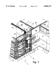
- FIG. 1 Another aspect of the present invention is a floor-to-ceiling partition wall of the type having a plurality of partition panels having panel frames interconnected along opposite side edges thereof and cover panels mounted on opposite side faces of the panel frames to form a partition wall having substantially planar side surfaces.
- the improvement comprises a utilities infeed panel with an infeed panel frame having opposite vertical side edges that are configured to interconnect with side edges of adjacent partition panel frames to enable installation of the utilities infeed panel between a pair of adjacent panels to form an integral part of the partition wall.
- the empty panel frame defines first and second opposite side faces, and a vertically-extending central space connected to an opening in the ceiling.
- a first cover panel is connected to the first side face of the empty panel frame.
- a second cover panel is removably connected to the second side face, and closes off the central space.
- the second cover panel permits access to the central space for utilities management upon removal of the second cover panel.
- the second cover panel defines an outer surface that is substantially co-planar with the side surfaces of adjacent partition panels.
- Yet another aspect of the present invention is a floor-to-ceiling utilities infeed panel including an infeed panel frame defining a vertical center plane, and first and second opposite side faces.
- the infeed panel frame includes a pair of horizontally spaced-apart vertical frame members, and upper and lower horizontal frame members extending between the vertical frame members and interconnecting the same.
- the horizontal frame members are disposed in an offset position from the center plane towards the first side face to define a central space within the panel that is connected with an opening in the ceiling for vertical routing of utilities.
- a first cover panel is connected to the first side face of the infeed panel frame.
- a second cover panel is removably connected to a second side face of the panel frame, and closes off the central space to facilitate installation and removal of utilities within the open space.
- Yet another aspect of the present invention is a floor-to-ceiling utilities infeed panel including an infeed panel frame defining first and second opposite faces. Cover panels are removably mounted on the side faces of the infeed panel frame to define a central space within the panel extending vertically to an opening in the ceiling to permit vertical routing of utilities through the central space within the infeed panel and through the ceiling.
- a termination panel support member is movably mounted to the infeed panel frame, and disposed within the central space.
- a termination panel is mounted on the support member within the central space, and includes a plurality of data connection ports.
- FIG. 1 is a fragmentary, perspective view of a floor-to-ceiling partition wall system embodying the present invention, wherein a portion thereof has been broken away to reveal internal construction;
- FIG. 2 is a fragmentary, perspective view of the infeed panel frame with extensions connected to the frame and extending through a suspended ceiling;
- FIG. 3 is a side elevational view of the infeed panel frame
- FIG. 4 is a front elevational view of the infeed panel frame
- FIG. 5 is a rear elevational view of the infeed panel frame
- FIG. 6 is a view of the panel-to-panel connector of FIG. 3;
- FIG. 7 is a view of the infeed panel frame of FIG. 4 showing the panel-to-panel connector bracket
- FIG. 8 is a view of the lower portion of the infeed panel frame of FIG. 3;
- FIG. 9 is a view of the upper portion of the infeed panel frame of FIG. 3;
- FIG. 10 is a cross-sectional view of the infeed panel frame taken along the line X--X; FIG. 4;
- FIG. 11 is a cross-sectional view of the infeed panel frame of FIG. 10;
- FIG. 12 is a perspective view of a first embodiment of the door used to support the termination panel
- FIG. 13 is a perspective view of a second embodiment of the door used to support the termination panel
- FIG. 14 is a top plane view of the utilities infeed panel showing the connection of the infeed panel frame extensions to a ceiling grid at an angle;
- FIG. 15 is a fragmentary, perspective view showing a bracket connected to a ceiling grid member
- FIG. 16 is a fragmentary, perspective view showing a utility support member and an extension extending between the ceiling trim pieces;
- FIG. 17 is a top plan view of the extension and utility support member
- FIG. 18 is a side elevational view of the extension and utility support member
- FIG. 19 is a front elevational view of the extension and utility support member
- FIG. 20 is a cross-sectional view taken along the line XX--XX; FIG. 23;
- FIG. 21 is a fragmentary, perspective view showing the ceiling trim pieces connected to an extension
- FIG. 22 is a fragmentary, perspective view of an upper cover panel
- FIG. 23 is an exploded perspective view showing the installation of the lower cover panels
- FIG. 24 is a top plan view of a lower cover panel
- FIG. 25 is a front elevational view of the lower cover panel
- FIG. 26 is a side elevational view of the lower cover panel
- FIG. 27 is a view of the cover panel in an installed position taken along the line XXVII--XXVII; FIG. 23.
- the terms "upper,” “lower,” “right,” “left,” “rear,” “front,” “vertical,” “horizontal,” and derivatives thereof shall relate to the invention as oriented in FIG. 1. However, it is to be understood that the invention may assume various orientations and step sequences, except where expressly specified to the contrary. It is also to be understood that the specific devices and processes illustrated in the attached drawings, and described in the following specification are simply exemplary embodiments of the inventive concepts defined in the appended claims. Hence, specific dimensions and other physical characteristics relating to the embodiments disclosed herein are not to be considered as limiting, unless the claims expressly state otherwise.
- the reference numeral 1 generally designates a partition wall system embodying the present invention, which is particularly designed for use in office spaces, and other similar settings and environments.
- the partition wall system 1 includes a plurality of partition panels 2, each having panel frames 3 interconnected by connectors, such as brackets 4 along opposite side edges 5 of the panel frames 3.
- the partition panels 2 have cover panels 6 mounted on opposite side faces 7 and 8 of the panel frames 3 to form partition wall 1 having substantially planar side surfaces.
- the partition wall system 1 includes a utilities infeed panel or chase 10 having an infeed panel frame 11 with opposite vertical side edges 12 and 13 that are interconnected with side edges 5 of adjacent partition panel frames 3 such that the utilities infeed panel 10 forms an integral portion of the partition wall 1.
- the infeed panel frame 11 defines first and second side faces 14 and 15, and a vertically-extending central space 16 connected to an opening 17 in the ceiling 18 (FIG. 2).
- a first cover panel 6 is connected to the first side face 14, and a second cover panel 6 is removably connected to the second side face 15, and closes off the central space 16.
- the second cover panel 6 permits access to the central space 16 for utilities management upon removal of the second cover panel 6.
- Partition panels 2 are described in detail in the above-referenced U.S. patent application Ser. No. 09/038,371, entitled “WALL PANEL PARTITION SYSTEM", filed Mar. 10, 1998, and hence will not be described in detail herein.
- Infeed panel frame 11 includes a pair of horizontally spaced-apart vertical frame members 21, and a plurality of horizontal frame members 22.
- the horizontal frame members 22 include horizontal rows of slots 23 for removably supporting hang-on accessory units, such as worksurfaces and the like at discreet, horizontally spaced-apart locations.
- horizontal frame members 22 also include a plurality of openings 24 that receive clips to removably retain cover panels 6 to the infeed panel frame 11.
- the upper surfaces of each horizontal frame member 22 include a plurality of openings 25 for support of a lower edge of a cover panel 6.
- a pair of tubular extensions 30 are fixed to the infeed panel frame 11, and extend upwardly above a suspended ceiling 18.
- a utility support member, such as horizontally-extending tube 31, is fixed to the upper portion 32 of each tubular extension 30 at a position above the suspended ceiling 18.
- Horizontally-extending tube 31 supports utility lines such as power and/or data lines 33 above the suspended ceiling 18 to facilitate routing of the data lines 33.
- a pair of ceiling trim pieces 34 are connected to the side faces of tubular extensions 30, and are spaced-apart to form an opening 35 that is connected with the opening 17 in the suspended ceiling 18 to permit a large volume of power and/or data lines 33 to pass upwardly through the suspended ceiling 18.
- Ceiling trim pieces 34 retain the upper edges of the upper cover panels 130, and also provide an appearance that is consistent with the ceiling track 26 of the adjacent partition panels 2. Accordingly, the need for a separate "power pole," or other ceiling infeed arrangement is eliminated.
- vertical frame members 21 define first and second side faces 36 and 37.
- Horizontal frame members 22 are welded or otherwise secured to the first side faces 36 of vertical frame members 21 such that the horizontal frame members 22 are offset from a center plane of the infeed panel frame 11.
- a plurality of skin support members 38 are welded or otherwise secured on the second side face 37 of vertical frame members 21.
- Skin support members 38 have substantially the same cross-sectional shape as horizontal frame members 22, and are located on second side faces 37 of vertical frame members 21 at the same vertical location as horizontal frame members 22.
- Skin support members 38 include openings 24 and 25 for support of cover panels 6.
- Skin support members 38 may include horizontal slots 28 for supporting hang-on accessory units if required for a particular application.
- Cover panel support members 38 are "cut-out" across the center portion of the infeed panel frame 11, defining an open central space 16 that permits lay-in of communications cabling 33 and the like from the side of the infeed panel.
- Central space 16 has a generally U-shaped cross section defined by the inner faces of horizontal frame members 22, and the inner faces of vertical frame members 21.
- a first embodiment of infeed panel frame 11 includes a pair of C-shaped stiles 39 that extend upwardly from the infeed panel frame 11 along the opposite side edges 12 and 13, and telescopically receive the tubular extensions 30 to interconnect the infeed panel frame 11 with the suspended ceiling 18.
- infeed panel frame 11 does not include C-shaped stiles 39, such that extensions 30 are secured directly to vertical frame members 21.
- Termination panels 41 include a plurality of data receptacles 42 that permit data or phone lines 43 to be removably connected to the termination panel 41 within the utilities infeed panel 10.
- a preferred embodiment utilizes a 24 port patch panel 41.
- This arrangement permits individual phone lines 43 to be connected or disconnected from a given line within the partition panel system, thereby eliminating rerouting of an individual phone line 43 from a "phone closet." Because the phone closet may be located a substantial distance from a given work area, considerable effort and associated expense can be encountered if a phone line must be rerouted along the entire partition panel section that extends between the phone closet and the individual work space.
- each connector bracket 4 includes a plate 47 having a plurality of openings 48 that receive fasteners to rigidly interconnect the opposite side edges 12 and 13 of the infeed panel frame 11 to the adjacent panel frames 3, thereby permitting installation of the utilities infeed panel within the partition wall system 1.
- the adjacent panels frames 3 also include connector brackets 4 that are substantially the same as that illustrated in FIG. 6, such that the openings 48 in connector brackets 4 of adjacent panel frames can be aligned to receive screws or other fasteners.
- plate 47 is welded to a pair of straps 49 that are spot welded to the vertical frame member 21 at 50.
- Opposite side edges 12 and 13 of infeed panel frame 11 may also be interconnected to partial height panels to provide utilities infeed from the ceiling 18.
- plate 47 includes an offset portion 51 to provide clearance for fasteners when utilities infeed panel 10 or a standard partition panel 2 are interconnected to another partition panel 2 in an off-module configuration.
- jack screws 20 are threadably mounted to the infeed panel frame 11, and pass through a lower horizontal frame member 27 to adjustably support the infeed panel frame 11 on the floor track 19.
- Base trim 52 clips onto the upwardly-extending flange 53 of floor track 19 to cover the lower edge of a cover panel 6.
- a C-channel 54 is secured to the first side face 36 of the vertical frame members 21, and extends horizontally between the first and second side edges 13 of the infeed panel frame 11.
- C-channel 54 forms a horizontal raceway or "expressway” 55 for lay-in of utility lines such as data lines 33 and/or power lines 29.
- Adjacent panels 2 also have C-channels 54, thereby permitting horizontal routing of utility lines throughout partition wall system 1.
- a pair of short C-channels 57 are mounted on the second side face 37 of vertical frame members 21. With further reference to FIG. 4, the short C-channels 57 provide an open central space, such that power and/or data lines 33 can be laid-in from the side of the partition panel, and routed upwardly through the ceiling.
- a polymer raceway cover 56 (FIG. 9) may be removably connected to the C-channel 54, and/or the short C-channels 57. Furthermore, as described below, the upper cover panel may extend downwardly over the C-channels 54 and 57, with the lower edge of the cover panel being supported by the upwardly-extending flange 58 such that a raceway cover 56 is not utilized.
- vertical frame members 21 include first and second channels 59 and 60 with outwardly opening sides that are juxtaposed in opposite directions to facilitate vertical routing of utilities therein along the opposite side faces 14, 15 of the infeed panel frame 11.
- End flanges 61 of vertical frame members 21 extend vertically along the side edges 12 and 13 of the infeed panel frame 11, and include an indented center 62 that forms a pocket that may receive a resilient, cylindrical seal 63.
- the resilient seal 63 is compressed between the end flanges 61 of adjacent panel frames to provide a light barrier between adjacent panels.
- a pair of doors 40 each support a termination or patch panel 41 to provide for plug-in of individual phone lines 43 within the partition panel system.
- Doors 40 are pivotally mounted to door bases 44 by piano hinges 45.
- Horizontal frame members 22 extend along the first side face 14 of the infeed panel frame 11 such that hang-on accessory units can be mounted to the first side face 14. Accordingly, door 40 pivots outwardly to provide access to the data lines 33 within the door 40 if access is blocked to the first side 14 due to the presence of hang-on partition units and the like that are secured to slots 23.
- Transverse wall 64 (FIG. 11), end wall 65, and end flange 61 of vertical frame members 21 form outer channels 66 that extend vertically adjacent the vertical side edges 12 and 13 of infeed panel frame 11.
- tubular extensions 30 are telescopically received within the outer channel 66, and are secured to the transverse walls 64 of vertical frame members 21 by a plurality of self-tapping screws or fasteners 67.
- each tubular extension 30 includes a plurality of clearance holes spaced at six-inch intervals that receive fasteners 67, such that the tubular extensions 30 can be extended upwardly or downwardly as required to account for variations in the floor-to-ceiling spacing.
- a first embodiment of the door 40 includes a door base 44 with a flange 70 that is spot-welded or otherwise secured to the inner flange 71 (FIG. 11) of the vertical frame member 21.
- a piano hinge 45 pivotally interconnects the door base 44 and the door 40.
- Door 40 includes an elongated opening 72, and upper and lower pairs of openings 73 that receive fasteners for mounting a data termination or patch panel 41.
- the data termination panel 41 fits over the opening 72, and includes a plurality of data receptacles 42 that facilitate reconfiguration of data lines such as phone lines and the like in a work space.
- the upper openings 73 are spaced-apart from the lower openings 73 at a nineteen-inch distance, such that a standard nineteen-inch termination panel 41 may be secured to the door 40.
- a preferred patch panel 41 is a nineteen-inch, 24 port model manufactured by Lucent Technologies, Inc., 600 Mountain Avenue, Murray Hill, N.J., part No. 1100CAT5PS-24B. If required, patch panel 41 may be mounted using an industry standard rack unit or bracket, such as part No. 1100C1-35-19, also manufactured by above-identified Lucent Technologies, Inc. Numerous other patch panel arrangements are also suitable for the present infeed panel.
- a pivotally mounted door arrangement facilitates access to both sides of patch panel 41
- a stationary bracket could be utilized to mount patch panel 41 to horizontal frame members 22, or to vertical frame members 21.
- a plurality of tie straps 81 may be received in the openings 79 in outer flange 80 of door 40 to secure the individual data lines 43.
- a second embodiment of the door 40 is substantially similar to the embodiment illustrated in FIG. 12, except that side flange 82 extends outwardly, and a commercially available wire retainer 83 is mounted thereto.
- Wire retainer 83 is polymer, with a generally rectangular cross-sectional shape, and has a plurality of slots 84 that receive and retain the individual phone lines 43.
- Door 40 may include a latch (not shown) to retain the door in the closed position.
- an adjustable assembly 91 interconnects the tubular extensions 30 with the standard ceiling grid 90 of a conventional suspended ceiling 18.
- Ceiling grid 90 includes a plurality of grid members 92, as well as a plurality of cross members 93, each of which has an inverted "T" cross-sectional shape.
- Horizontal support tubes 94 are connected to cross members 93 by brackets 95 adjacent each end of the support tubes 94.
- Straps 96 interconnect tubular extensions 30 to the horizontal support tubes 94.
- Brackets 95 can be mounted at various locations along the cross member 93, and straps 96 can also be secured to the horizontal support tubes 94 at various locations, thereby permitting utilities infeed panel 10 to be mounted at an angle to the ceiling grid as illustrated in FIG. 14.
- each end portion 98 of each support tube 94 is slidably received within an opening 97 in a bracket 95.
- Sidewalls 99 of bracket 95 include cut-out portions 100 that receive the upper leg 101 of a cross member 93 of the ceiling grid 90.
- strap 96 receives a nylon bushing 103 having a rectangular opening 104 therethrough that receives tubular extension 30.
- a plate 105 of strap 96 has a threaded opening 106 that receives a fastener 107 that abuts the sidewall 108 of support tube 94 to secure the strap 96 and tubular extension 30 in a desired position.
- Support tube 94 passes through a pair of square openings 109 in strap 96 to slidably support strap 96.
- horizontal tube 31 is welded to tubular extension 30, and extends horizontally therefrom.
- Plate 110 is welded to the end of horizontal tube 31, and includes an upwardly-extending portion 111 forming a utilities retaining member.
- Horizontal tube 31 is circular in cross section, and provides support for routing data lines 33 above ceiling 18.
- a plurality of holes 112 are provided in at least two of the side faces of the tubular extensions 30. Holes 112 receive fasteners 67 to retain extension 30 within outer channel 66 of vertical frame members 21 (see also FIG. 11) at a selected height.
- a plurality of openings are also provided in transverse walls 64 and 65 of vertical frame member 21, such that tubular extension 30 can be moved upwardly or downwardly as required at six-inch increments to adjust the vertical location of the horizontal tube 31 at the required distance above the ceiling 18.
- ceiling trim pieces 34 include downwardly-extending outer sidewalls 120, and downwardly-extending inner flanges 121 that form a cover panel retaining channel 122.
- Each ceiling trim piece 34 includes a tab 123 that extends along the outer sidewall 125 (see also FIG. 11) of extension 30, with a clearance hole therein that receives fastener 124 to interconnect a pair of ceiling trim pieces 34.
- Upwardly-extending tabs 126 receive fasteners 128 to secure the ceiling trim pieces 34 to the opposite sidewalls 127 of tubular extension 30.
- Infeed panel frame 11 may include a U-shaped horizontal member 132 that is secured to the top of C-channel 54 and short C-channels 57.
- Upper cover panel 130 includes a downwardly-opening hook or flange 134 extending along the lower edge 135 that fits over the upwardly-extending flange 133 of U-shaped member 132 to support the lower edge 135 of upper cover panel 130.
- the upper edge 131 of upper cover panel 130 is received within channel 122 of ceiling trim piece 34. Due to variations in the floor-to-ceiling spacing, the upper portion of upper cover panel 130 may be cut off to reduce the overall height of upper cover panel 130. Cutting off the upper end of cover panel 130 produces an upper end 131 of upper cover panel 130 that may be irregular and/or unsightly.
- Outer sidewall 120 and inner flange 121 of ceiling trim pieces 34 retain and receive the upper portion 131 of cover panel 130 to provide a finished appearance.
- Inner flanges 121 define an opening 136 therebetween that permits routing of data lines 33 upwardly through the ceiling 18 (see also FIG. 16). Opening 136 extends between extensions 30, and provides a relatively large opening, such that large numbers of data and/or power lines can be routed through the ceiling 18.
- an upper cover panel 130 may comprise a sheet metal skin 145 that is folded over along the top edge 131 to form downwardly-extending flange 147.
- a downwardly-opening hook or flange 134 extends along the lower edge 135 of upper cover panel 130.
- Cover panel 130 may include a sound-insulating mat or other material 146, and vertical braces 148 may also be provided.
- lower cover panels 6 may be secured to skin support members 38 on the open side face 15 of infeed panel frame 11, as well as to the horizontal frame members 22 on the closed, or first side face 14 of infeed panel frame 11.
- Lower cover panels 6 include a plurality of clips 155 along upper edge 156 that are received within openings 24 (see also FIG. 7) of skin support members 38 or horizontal frame members 22.
- skins support members 38 and horizontal frame members 22 include openings or slots 25 in the upper, horizontal surface. Openings 25 receive fingers or tabs 157 located along the lower edge 158 of a lower cover panel 6.
- Lower cover panels 6 are installed by inserting fingers 157 in openings 25, and upper edge 156 is then rotated inwardly until the clips 155 engage openings 24 in a horizontal frame member 22 or a skin support member 38.
- cover panels 6 include a downwardly-extending flange 159 having a lower edge 160.
- Clips 155 include a first tab 161 that fits over the lower edge 160 of flange 159, and a second tab 162 is received within an opening (not shown) in flange 159 to retain clip 155.
- An upwardly-extending flange 163 extends along the lower edge 158 of cover panel 6 and terminates at an upper edge 164.
- Each finger 157 is pivotally mounted to the flange 163 at 165 to permit rotation of finger 157 to provide clearance such that hang-on accessory units can be mounted on slots 123 if required.
- a flexible offset tab 166 contacts the flange 163 to provide a frictional engagement to retain fingers 157 at a selected angular orientation.
- a flexible light seal 167 extends along the lower edge 158 of cover panel 6 to prevent light transmission between the edges of adjacent cover panels 6.
- each clip 155 has a generally V-shape with an upper leg 170, and a lower leg 171.
- Upper and lower legs 170 and 171 flex towards one another during insertion of clip 155 in slot 24.
- upper leg 170 flexes upwardly, and the end or edge 172 of upper leg 170 abuts the inner surface 173 of skin support member 38 or horizontal frame member 22 thereby retaining cover panel 6 to infeed panel frame 11.
- the utilities infeed panel 10 of the present invention forms an integral part of a partition wall system 1, thereby providing a uniform appearance.
- the opening 136 along the top edge of the utilities infeed panel connects to an opening in the ceiling, thereby permitting a large number of utilities, such as data and/or power lines 33 to be routed into the utilities infeed panel 10 from above the suspended ceiling 18.
- the tubular extensions 30 and horizontal extension tubes 31 can be easily adjusted to accommodate various floor-to-ceiling dimensions, and the jack screws and floor track 19 permit leveling and integration of the utilities infeed panel within the partition wall system 1.
- the connector brackets 4 located on the opposite vertical side edges 12 and 13 of the utilities infeed panel 10 permit a rigid interconnection to the side edges of the adjacent partition panels 2.
- the termination or patch panel 41 is mounted on a door 40 that is pivotally mounted to the infeed panel frame 11 to provide a connection point for individual phone lines 43 adjacent the individual work spaces.
- Horizontal frame members 22 are offset, providing a vertically-extending central space 16 to permit lay-in of vertical utility lines within the utilities infeed panel 10.
- Skin support members 38 provide openings for mounting of cover panels in the same manner as the cover panels utilized on the adjacent partition panels 2, thereby eliminating the need for a special cover panel arrangement for the utilities infeed panel 10.
Abstract
Description
Claims (40)
Priority Applications (1)
| Application Number | Priority Date | Filing Date | Title |
|---|---|---|---|
| US09/087,562 US6003273A (en) | 1998-05-29 | 1998-05-29 | Utilities infeed panel |
Applications Claiming Priority (1)
| Application Number | Priority Date | Filing Date | Title |
|---|---|---|---|
| US09/087,562 US6003273A (en) | 1998-05-29 | 1998-05-29 | Utilities infeed panel |
Publications (1)
| Publication Number | Publication Date |
|---|---|
| US6003273A true US6003273A (en) | 1999-12-21 |
Family
ID=22205915
Family Applications (1)
| Application Number | Title | Priority Date | Filing Date |
|---|---|---|---|
| US09/087,562 Expired - Lifetime US6003273A (en) | 1998-05-29 | 1998-05-29 | Utilities infeed panel |
Country Status (1)
| Country | Link |
|---|---|
| US (1) | US6003273A (en) |
Cited By (27)
| Publication number | Priority date | Publication date | Assignee | Title |
|---|---|---|---|---|
| US6202381B1 (en) | 1996-06-07 | 2001-03-20 | Herman Miller, Inc. | Method for reconfiguring a wall panel system |
| US6223485B1 (en) | 1996-06-07 | 2001-05-01 | Herman Miller, Inc. | Wall panel system |
| US6295764B1 (en) | 1999-06-04 | 2001-10-02 | Herman Miller, Inc. | Stackable wall panel system |
| US6322176B1 (en) * | 1998-12-29 | 2001-11-27 | Avaya Technology Corp. | Transmission media patch panel modular cabinetry system |
| US6393782B1 (en) | 1999-06-04 | 2002-05-28 | Herman Miller, Inc. | Stackable wall panel system |
| US6408579B1 (en) | 2000-04-25 | 2002-06-25 | Steelcase Development Corporation | Thin panel beam |
| US6489565B1 (en) | 2000-09-15 | 2002-12-03 | Chatsworth Products, Inc. | Vertical cable management rack |
| US20030097806A1 (en) * | 1996-03-05 | 2003-05-29 | Brown John G. | Inner accessible commutering enterprise structure interfaced with one or more workplace, vehicle or home commutering stations |
| US6600106B2 (en) * | 2001-07-11 | 2003-07-29 | Adc Telecommunications, Inc. | Cable management bar and patch panel |
| US6729085B2 (en) | 2001-02-09 | 2004-05-04 | Herman Miller, Inc. | Wall panel system |
| US20050072090A1 (en) * | 2001-04-20 | 2005-04-07 | Mclaughlin Thomas | Ceiling suspension with cable pathway |
| US7091418B1 (en) | 2005-04-01 | 2006-08-15 | Adc Telecommunications, Inc. | Cable management bar and patch panel |
| US20060277838A1 (en) * | 2002-06-07 | 2006-12-14 | Prototype Productions, Inc. | Structure having preinstalled utilities and amenities |
| US20070207305A1 (en) * | 2006-03-06 | 2007-09-06 | York International Corporation | Panel construction for an air handling unit |
| WO2008141610A1 (en) * | 2007-05-24 | 2008-11-27 | Voelker Manfred | Pre-assembly wall for practice facilities or for intensive care or inpatient hospital rooms |
| US20090313928A1 (en) * | 2008-06-24 | 2009-12-24 | Environmental Interiors, Inc. | High impact, moisture resistant wall panel system |
| US20100082309A1 (en) * | 2008-09-29 | 2010-04-01 | International Business Machines Corporation | System and method for dynamically modeling data center partitions |
| US20100082178A1 (en) * | 2008-09-29 | 2010-04-01 | International Business Machines Corporation | System and method to dynamically change data center partitions |
| US7778513B2 (en) | 2005-01-21 | 2010-08-17 | Cooper Technologies Company | Cable manager with adjustable cable guides |
| US7952023B2 (en) | 2005-09-08 | 2011-05-31 | Panduit Corp. | Wall mounted enclosure with rotating patch panel frame |
| US9351427B2 (en) | 2013-12-17 | 2016-05-24 | Chatsworth Products, Inc. | Electronic equipment enclosure |
| US10159616B2 (en) | 2008-10-16 | 2018-12-25 | Wittrock Enterprises Llc | Modular wall for dividing rooms in a healthcare facility |
| US10595442B2 (en) | 2013-01-11 | 2020-03-17 | Chatsworth Products, Inc. | Data processing equipment structure |
| US11211755B2 (en) | 2018-10-26 | 2021-12-28 | Poppin Inc. | Power rail system |
| US11299887B2 (en) * | 2019-11-08 | 2022-04-12 | Teknion Limited | Leveling assembly |
| US20230111235A1 (en) * | 2019-12-16 | 2023-04-13 | Falkbuilt Ltd. | Drop-in ceiling wall system |
| US11909154B1 (en) | 2021-03-08 | 2024-02-20 | Chatsworth Products, Inc. | Endcap for establishing electrical bonding connection |
Citations (36)
| Publication number | Priority date | Publication date | Assignee | Title |
|---|---|---|---|---|
| US2896009A (en) * | 1955-05-17 | 1959-07-21 | Jack E Caveney | Wiring duct |
| US3135469A (en) * | 1962-04-02 | 1964-06-02 | Neil H Hanson | Portable electrical outlet and lighting assembly |
| US3377756A (en) * | 1964-10-22 | 1968-04-16 | Movable Interior Products | Demountable building partition construction |
| US3823251A (en) * | 1972-06-12 | 1974-07-09 | Mesco Metal Buildings Corp | Electrical connector for interior wall panels |
| US3831330A (en) * | 1972-03-14 | 1974-08-27 | Steelcase Inc | Panel system |
| US4015397A (en) * | 1974-04-29 | 1977-04-05 | Textron, Inc. | Service poles and accessories |
| US4178468A (en) * | 1977-05-04 | 1979-12-11 | Square D Company | Duct post |
| US4199206A (en) * | 1976-11-01 | 1980-04-22 | Haworth Mfg., Inc. | Wall panel with prewired power system |
| US4230900A (en) * | 1978-06-13 | 1980-10-28 | Steelcase Inc., | Power pole assembly |
| US4252989A (en) * | 1976-06-03 | 1981-02-24 | Cts Corporation | Adjustable service column |
| US4278834A (en) * | 1978-12-06 | 1981-07-14 | Westinghouse Electric Corp. | Versatile, electrified space dividing wall panel system |
| US4338485A (en) * | 1980-11-10 | 1982-07-06 | Hill-Rom Company, Inc. | Headwall unit for patient servicing and method for installation |
| US4353411A (en) * | 1980-02-04 | 1982-10-12 | Harter James L | Architectural support and service assembly |
| US4373111A (en) * | 1980-04-21 | 1983-02-08 | Butler Manufacturing Company | Service poles |
| US4577055A (en) * | 1984-01-16 | 1986-03-18 | Harvey Hubbell Incorporated | Power pole wiring assembly |
| US4716698A (en) * | 1986-06-06 | 1988-01-05 | Haworth, Inc. | Wall system with split pole for lay-in wiring |
| US4902852A (en) * | 1989-02-15 | 1990-02-20 | Hubbell Incorporated | Power pole wiring chamber |
| US5044135A (en) * | 1989-06-13 | 1991-09-03 | Hon Industries Inc. | Cluster work station system |
| US5081809A (en) * | 1989-05-12 | 1992-01-21 | Environmental Panelling Systems (Pty) Ltd. | Demountable wall panelling |
| US5115377A (en) * | 1991-06-03 | 1992-05-19 | Cincinnati Milacron Inc. | Wireway channel assembly for electrical cabinets |
| US5195286A (en) * | 1991-05-09 | 1993-03-23 | Westinghouse Electric Corp. | Ceiling infeed module |
| US5207041A (en) * | 1990-10-19 | 1993-05-04 | Design Funktion Mobler Ab | Service wall structure |
| US5214890A (en) * | 1991-04-29 | 1993-06-01 | Teknion Furniture Systems | Office panel with lay-in communication cable capability |
| US5277005A (en) * | 1992-05-04 | 1994-01-11 | Teknion Furniture Systems | Free-standing partitioning panel |
| US5277007A (en) * | 1992-05-04 | 1994-01-11 | Teknion Furniture Systems | Office panel with top lay-in passageway |
| US5326934A (en) * | 1991-07-08 | 1994-07-05 | Communication Integrators Inc. | Multi-commodity connectivity system |
| US5341615A (en) * | 1991-01-10 | 1994-08-30 | Steelcase Inc. | Utility panel system |
| US5357055A (en) * | 1992-10-26 | 1994-10-18 | Sireci Donald J | Electric routing system for modular office partitioning systems |
| US5362923A (en) * | 1991-11-27 | 1994-11-08 | Herman Miller, Inc. | System for distributing and managing cabling within a work space |
| US5394658A (en) * | 1988-07-29 | 1995-03-07 | Schreiner; Charles P. | Free standing modular furniture and wall system |
| US5511349A (en) * | 1992-11-04 | 1996-04-30 | Herman Miller, Inc. | Raceway cable retention and accommodation apparatus |
| US5685113A (en) * | 1995-06-05 | 1997-11-11 | Knoll, Inc. | Lay-in wireways for a space divider system |
| US5697193A (en) * | 1993-05-18 | 1997-12-16 | Steelcase Inc. | Utility distribution system for open office plans and the like |
| US5778612A (en) * | 1990-11-28 | 1998-07-14 | Kissinger; Terrance G. | Partition panel containing data processing or communications equipment |
| US5801921A (en) * | 1996-11-19 | 1998-09-01 | Symex, Inc. | Integrated data, voice, and video communication network |
| US5852904A (en) * | 1996-08-05 | 1998-12-29 | Haworth, Inc. | Panel arrangement |
-
1998
- 1998-05-29 US US09/087,562 patent/US6003273A/en not_active Expired - Lifetime
Patent Citations (36)
| Publication number | Priority date | Publication date | Assignee | Title |
|---|---|---|---|---|
| US2896009A (en) * | 1955-05-17 | 1959-07-21 | Jack E Caveney | Wiring duct |
| US3135469A (en) * | 1962-04-02 | 1964-06-02 | Neil H Hanson | Portable electrical outlet and lighting assembly |
| US3377756A (en) * | 1964-10-22 | 1968-04-16 | Movable Interior Products | Demountable building partition construction |
| US3831330A (en) * | 1972-03-14 | 1974-08-27 | Steelcase Inc | Panel system |
| US3823251A (en) * | 1972-06-12 | 1974-07-09 | Mesco Metal Buildings Corp | Electrical connector for interior wall panels |
| US4015397A (en) * | 1974-04-29 | 1977-04-05 | Textron, Inc. | Service poles and accessories |
| US4252989A (en) * | 1976-06-03 | 1981-02-24 | Cts Corporation | Adjustable service column |
| US4199206A (en) * | 1976-11-01 | 1980-04-22 | Haworth Mfg., Inc. | Wall panel with prewired power system |
| US4178468A (en) * | 1977-05-04 | 1979-12-11 | Square D Company | Duct post |
| US4230900A (en) * | 1978-06-13 | 1980-10-28 | Steelcase Inc., | Power pole assembly |
| US4278834A (en) * | 1978-12-06 | 1981-07-14 | Westinghouse Electric Corp. | Versatile, electrified space dividing wall panel system |
| US4353411A (en) * | 1980-02-04 | 1982-10-12 | Harter James L | Architectural support and service assembly |
| US4373111A (en) * | 1980-04-21 | 1983-02-08 | Butler Manufacturing Company | Service poles |
| US4338485A (en) * | 1980-11-10 | 1982-07-06 | Hill-Rom Company, Inc. | Headwall unit for patient servicing and method for installation |
| US4577055A (en) * | 1984-01-16 | 1986-03-18 | Harvey Hubbell Incorporated | Power pole wiring assembly |
| US4716698A (en) * | 1986-06-06 | 1988-01-05 | Haworth, Inc. | Wall system with split pole for lay-in wiring |
| US5394658A (en) * | 1988-07-29 | 1995-03-07 | Schreiner; Charles P. | Free standing modular furniture and wall system |
| US4902852A (en) * | 1989-02-15 | 1990-02-20 | Hubbell Incorporated | Power pole wiring chamber |
| US5081809A (en) * | 1989-05-12 | 1992-01-21 | Environmental Panelling Systems (Pty) Ltd. | Demountable wall panelling |
| US5044135A (en) * | 1989-06-13 | 1991-09-03 | Hon Industries Inc. | Cluster work station system |
| US5207041A (en) * | 1990-10-19 | 1993-05-04 | Design Funktion Mobler Ab | Service wall structure |
| US5778612A (en) * | 1990-11-28 | 1998-07-14 | Kissinger; Terrance G. | Partition panel containing data processing or communications equipment |
| US5341615A (en) * | 1991-01-10 | 1994-08-30 | Steelcase Inc. | Utility panel system |
| US5214890A (en) * | 1991-04-29 | 1993-06-01 | Teknion Furniture Systems | Office panel with lay-in communication cable capability |
| US5195286A (en) * | 1991-05-09 | 1993-03-23 | Westinghouse Electric Corp. | Ceiling infeed module |
| US5115377A (en) * | 1991-06-03 | 1992-05-19 | Cincinnati Milacron Inc. | Wireway channel assembly for electrical cabinets |
| US5326934A (en) * | 1991-07-08 | 1994-07-05 | Communication Integrators Inc. | Multi-commodity connectivity system |
| US5362923A (en) * | 1991-11-27 | 1994-11-08 | Herman Miller, Inc. | System for distributing and managing cabling within a work space |
| US5277005A (en) * | 1992-05-04 | 1994-01-11 | Teknion Furniture Systems | Free-standing partitioning panel |
| US5277007A (en) * | 1992-05-04 | 1994-01-11 | Teknion Furniture Systems | Office panel with top lay-in passageway |
| US5357055A (en) * | 1992-10-26 | 1994-10-18 | Sireci Donald J | Electric routing system for modular office partitioning systems |
| US5511349A (en) * | 1992-11-04 | 1996-04-30 | Herman Miller, Inc. | Raceway cable retention and accommodation apparatus |
| US5697193A (en) * | 1993-05-18 | 1997-12-16 | Steelcase Inc. | Utility distribution system for open office plans and the like |
| US5685113A (en) * | 1995-06-05 | 1997-11-11 | Knoll, Inc. | Lay-in wireways for a space divider system |
| US5852904A (en) * | 1996-08-05 | 1998-12-29 | Haworth, Inc. | Panel arrangement |
| US5801921A (en) * | 1996-11-19 | 1998-09-01 | Symex, Inc. | Integrated data, voice, and video communication network |
Non-Patent Citations (1)
| Title |
|---|
| Exhibit A is a prior art support used to connect a power pole to a ceiling grid. * |
Cited By (52)
| Publication number | Priority date | Publication date | Assignee | Title |
|---|---|---|---|---|
| US20030097806A1 (en) * | 1996-03-05 | 2003-05-29 | Brown John G. | Inner accessible commutering enterprise structure interfaced with one or more workplace, vehicle or home commutering stations |
| US6393783B2 (en) | 1996-06-07 | 2002-05-28 | Herman Miller, Inc. | Wall panel |
| US6223485B1 (en) | 1996-06-07 | 2001-05-01 | Herman Miller, Inc. | Wall panel system |
| US6202381B1 (en) | 1996-06-07 | 2001-03-20 | Herman Miller, Inc. | Method for reconfiguring a wall panel system |
| US6301847B1 (en) | 1996-06-07 | 2001-10-16 | Herman Miller, Inc. | Wall panel |
| US6339907B1 (en) | 1996-06-07 | 2002-01-22 | Herman Miller, Inc. | System of wall panels |
| US6322176B1 (en) * | 1998-12-29 | 2001-11-27 | Avaya Technology Corp. | Transmission media patch panel modular cabinetry system |
| US6393782B1 (en) | 1999-06-04 | 2002-05-28 | Herman Miller, Inc. | Stackable wall panel system |
| US6295764B1 (en) | 1999-06-04 | 2001-10-02 | Herman Miller, Inc. | Stackable wall panel system |
| US6408579B1 (en) | 2000-04-25 | 2002-06-25 | Steelcase Development Corporation | Thin panel beam |
| US6489565B1 (en) | 2000-09-15 | 2002-12-03 | Chatsworth Products, Inc. | Vertical cable management rack |
| US7119282B2 (en) | 2000-09-15 | 2006-10-10 | Chatsworth Products, Inc. | Vertical cable management rack |
| US6605782B1 (en) | 2000-09-15 | 2003-08-12 | Chatsworth Products, Inc. | Vertical cable management rack |
| US20040007372A1 (en) * | 2000-09-15 | 2004-01-15 | Chatsworth Products, Inc. | Vertical cable management rack |
| US6729085B2 (en) | 2001-02-09 | 2004-05-04 | Herman Miller, Inc. | Wall panel system |
| US6820388B2 (en) | 2001-02-09 | 2004-11-23 | Herman Miller, Inc. | Stackable wall panel assembly and connector therefor |
| US20050072090A1 (en) * | 2001-04-20 | 2005-04-07 | Mclaughlin Thomas | Ceiling suspension with cable pathway |
| US6600106B2 (en) * | 2001-07-11 | 2003-07-29 | Adc Telecommunications, Inc. | Cable management bar and patch panel |
| US20060277838A1 (en) * | 2002-06-07 | 2006-12-14 | Prototype Productions, Inc. | Structure having preinstalled utilities and amenities |
| US7778513B2 (en) | 2005-01-21 | 2010-08-17 | Cooper Technologies Company | Cable manager with adjustable cable guides |
| US7091418B1 (en) | 2005-04-01 | 2006-08-15 | Adc Telecommunications, Inc. | Cable management bar and patch panel |
| US20060225912A1 (en) * | 2005-04-01 | 2006-10-12 | Adc Telecommunications, Inc. | Cable Management Bar and Patch Panel |
| US7200931B2 (en) | 2005-04-01 | 2007-04-10 | Adc Telecommunications, Inc. | Cable management bar and patch panel |
| US7952023B2 (en) | 2005-09-08 | 2011-05-31 | Panduit Corp. | Wall mounted enclosure with rotating patch panel frame |
| US20070207305A1 (en) * | 2006-03-06 | 2007-09-06 | York International Corporation | Panel construction for an air handling unit |
| WO2008141610A1 (en) * | 2007-05-24 | 2008-11-27 | Voelker Manfred | Pre-assembly wall for practice facilities or for intensive care or inpatient hospital rooms |
| US7810289B2 (en) | 2008-06-24 | 2010-10-12 | Environmental Interiors, Inc. | High impact, moisture resistant wall panel system |
| US20090313932A1 (en) * | 2008-06-24 | 2009-12-24 | Environmental Interiors, Inc. | High impact, moisture resistant wall panel system |
| US20090313928A1 (en) * | 2008-06-24 | 2009-12-24 | Environmental Interiors, Inc. | High impact, moisture resistant wall panel system |
| US7805899B2 (en) | 2008-06-24 | 2010-10-05 | Environmental Interiors, Inc. | High impact, moisture resistant wall panel system |
| US20100082309A1 (en) * | 2008-09-29 | 2010-04-01 | International Business Machines Corporation | System and method for dynamically modeling data center partitions |
| US8983675B2 (en) * | 2008-09-29 | 2015-03-17 | International Business Machines Corporation | System and method to dynamically change data center partitions |
| US9250663B2 (en) | 2008-09-29 | 2016-02-02 | International Business Machines Corporation | System and method for dynamically modeling data center partitions |
| US10884387B2 (en) | 2008-09-29 | 2021-01-05 | International Business Machines Corporation | System and method to dynamically change data center partitions |
| US20100082178A1 (en) * | 2008-09-29 | 2010-04-01 | International Business Machines Corporation | System and method to dynamically change data center partitions |
| US9939796B2 (en) | 2008-09-29 | 2018-04-10 | International Business Machines Corporation | System and method to dynamically change data center partitions |
| US10159616B2 (en) | 2008-10-16 | 2018-12-25 | Wittrock Enterprises Llc | Modular wall for dividing rooms in a healthcare facility |
| US11647610B2 (en) | 2013-01-11 | 2023-05-09 | Chatsworth Products, Inc. | Modular thermal isolation barrier for data processing equipment structure |
| US10595442B2 (en) | 2013-01-11 | 2020-03-17 | Chatsworth Products, Inc. | Data processing equipment structure |
| US9549487B2 (en) | 2013-12-17 | 2017-01-17 | Chatsworth Products, Inc. | Electronic equipment enclosure |
| US10356951B2 (en) | 2013-12-17 | 2019-07-16 | Chatsworth Products, Inc. | Electronic equipment enclosure |
| US9949406B2 (en) | 2013-12-17 | 2018-04-17 | Chatsworth Products, Inc. | Electronic equipment enclosure |
| US10674634B2 (en) | 2013-12-17 | 2020-06-02 | Chatsworth Products, Inc. | Electronic equipment enclosure |
| US9420727B2 (en) | 2013-12-17 | 2016-08-16 | Chatsworth Products, Inc. | Electronic equipment enclosure |
| US11083108B2 (en) | 2013-12-17 | 2021-08-03 | Chatsworth Products, Inc. | Electronic equipment enclosure |
| US9351427B2 (en) | 2013-12-17 | 2016-05-24 | Chatsworth Products, Inc. | Electronic equipment enclosure |
| US11211755B2 (en) | 2018-10-26 | 2021-12-28 | Poppin Inc. | Power rail system |
| US11299887B2 (en) * | 2019-11-08 | 2022-04-12 | Teknion Limited | Leveling assembly |
| US11686090B2 (en) | 2019-11-08 | 2023-06-27 | Teknion Limited | Leveling assembly |
| US20230111235A1 (en) * | 2019-12-16 | 2023-04-13 | Falkbuilt Ltd. | Drop-in ceiling wall system |
| US11795683B2 (en) * | 2019-12-16 | 2023-10-24 | Falkbuilt Ltd. | Drop-in ceiling wall system |
| US11909154B1 (en) | 2021-03-08 | 2024-02-20 | Chatsworth Products, Inc. | Endcap for establishing electrical bonding connection |
Similar Documents
| Publication | Publication Date | Title |
|---|---|---|
| US6003273A (en) | Utilities infeed panel | |
| US6128877A (en) | Variable width end panel | |
| US6047508A (en) | Wall panel partition system | |
| US6141925A (en) | Clear wall panel system | |
| US5809708A (en) | Integrated prefabricated furniture system for fitting-out open plan building space | |
| US6591563B2 (en) | Panel system | |
| US6951085B2 (en) | Utility panel system | |
| US6276102B1 (en) | Integrated prefabricated furniture system for fitting-out open plan building space | |
| US7210270B1 (en) | Partition system with elevated raceway | |
| US5768840A (en) | Integrated utility distribution and panel system | |
| US7150127B2 (en) | Partition system | |
| US6415567B1 (en) | Furniture post top cap attachment and trim registry | |
| US20140261100A1 (en) | Office furniture system | |
| US6000179A (en) | Stacking panel and off-module panel connections | |
| US6408579B1 (en) | Thin panel beam | |
| US6533019B1 (en) | Partition panel with infill arrangement | |
| US6397534B1 (en) | Cover member lock for partition panels | |
| US6351917B1 (en) | Stacking connector for partitions | |
| US6481163B1 (en) | Partition panel | |
| US5943833A (en) | In-floor utility outlet | |
| CA2297862A1 (en) | Method of partitioning office spaces | |
| GB2346905A (en) | Framework for office partition | |
| JP3036355B2 (en) | Multifunctional electrical / information panel for partition | |
| MXPA97004894A (en) | Prefabricated and integrated furniture system for equiping open plane spaces in construction |
Legal Events
| Date | Code | Title | Description |
|---|---|---|---|
| AS | Assignment |
Owner name: STEELCASE INC., MICHIGAN Free format text: ASSIGNMENT OF ASSIGNORS INTEREST;ASSIGNORS:ELSHOLZ, MICHAEL D.;JEFFERS, ROBERT E.;MEAD, KARL J.;REEL/FRAME:009230/0183 Effective date: 19980529 |
|
| AS | Assignment |
Owner name: STEELCASE DEVELOPMENT INC., A CORPORATION OF MICHI Free format text: ASSIGNMENT OF ASSIGNORS INTEREST;ASSIGNOR:STEELCASE INC., A CORPORATION OF MICHIGAN;REEL/FRAME:010159/0755 Effective date: 19990701 |
|
| STCF | Information on status: patent grant |
Free format text: PATENTED CASE |
|
| CC | Certificate of correction | ||
| FPAY | Fee payment |
Year of fee payment: 4 |
|
| FEPP | Fee payment procedure |
Free format text: PAYOR NUMBER ASSIGNED (ORIGINAL EVENT CODE: ASPN); ENTITY STATUS OF PATENT OWNER: LARGE ENTITY |
|
| FPAY | Fee payment |
Year of fee payment: 8 |
|
| FEPP | Fee payment procedure |
Free format text: PAYER NUMBER DE-ASSIGNED (ORIGINAL EVENT CODE: RMPN); ENTITY STATUS OF PATENT OWNER: LARGE ENTITY Free format text: PAYOR NUMBER ASSIGNED (ORIGINAL EVENT CODE: ASPN); ENTITY STATUS OF PATENT OWNER: LARGE ENTITY |
|
| FPAY | Fee payment |
Year of fee payment: 12 |