US6002995A - Apparatus and method for displaying control information of cameras connected to a network - Google Patents
Apparatus and method for displaying control information of cameras connected to a network Download PDFInfo
- Publication number
- US6002995A US6002995A US08/766,107 US76610796A US6002995A US 6002995 A US6002995 A US 6002995A US 76610796 A US76610796 A US 76610796A US 6002995 A US6002995 A US 6002995A
- Authority
- US
- United States
- Prior art keywords
- cameras
- camera
- symbols
- displaying
- display
- Prior art date
- Legal status (The legal status is an assumption and is not a legal conclusion. Google has not performed a legal analysis and makes no representation as to the accuracy of the status listed.)
- Expired - Lifetime
Links
Images


Classifications
-
- H—ELECTRICITY
- H04—ELECTRIC COMMUNICATION TECHNIQUE
- H04N—PICTORIAL COMMUNICATION, e.g. TELEVISION
- H04N7/00—Television systems
- H04N7/14—Systems for two-way working
- H04N7/141—Systems for two-way working between two video terminals, e.g. videophone
- H04N7/147—Communication arrangements, e.g. identifying the communication as a video-communication, intermediate storage of the signals
-
- H—ELECTRICITY
- H04—ELECTRIC COMMUNICATION TECHNIQUE
- H04N—PICTORIAL COMMUNICATION, e.g. TELEVISION
- H04N23/00—Cameras or camera modules comprising electronic image sensors; Control thereof
- H04N23/60—Control of cameras or camera modules
- H04N23/63—Control of cameras or camera modules by using electronic viewfinders
- H04N23/631—Graphical user interfaces [GUI] specially adapted for controlling image capture or setting capture parameters
-
- H—ELECTRICITY
- H04—ELECTRIC COMMUNICATION TECHNIQUE
- H04N—PICTORIAL COMMUNICATION, e.g. TELEVISION
- H04N23/00—Cameras or camera modules comprising electronic image sensors; Control thereof
- H04N23/60—Control of cameras or camera modules
- H04N23/66—Remote control of cameras or camera parts, e.g. by remote control devices
- H04N23/661—Transmitting camera control signals through networks, e.g. control via the Internet
-
- H—ELECTRICITY
- H04—ELECTRIC COMMUNICATION TECHNIQUE
- H04N—PICTORIAL COMMUNICATION, e.g. TELEVISION
- H04N23/00—Cameras or camera modules comprising electronic image sensors; Control thereof
- H04N23/60—Control of cameras or camera modules
- H04N23/695—Control of camera direction for changing a field of view, e.g. pan, tilt or based on tracking of objects
-
- H—ELECTRICITY
- H04—ELECTRIC COMMUNICATION TECHNIQUE
- H04N—PICTORIAL COMMUNICATION, e.g. TELEVISION
- H04N7/00—Television systems
- H04N7/16—Analogue secrecy systems; Analogue subscription systems
- H04N7/173—Analogue secrecy systems; Analogue subscription systems with two-way working, e.g. subscriber sending a programme selection signal
-
- H—ELECTRICITY
- H04—ELECTRIC COMMUNICATION TECHNIQUE
- H04N—PICTORIAL COMMUNICATION, e.g. TELEVISION
- H04N7/00—Television systems
- H04N7/18—Closed-circuit television [CCTV] systems, i.e. systems in which the video signal is not broadcast
- H04N7/181—Closed-circuit television [CCTV] systems, i.e. systems in which the video signal is not broadcast for receiving images from a plurality of remote sources
Definitions
- This invention relates to a control system for cameras connected to a network.
- Such monitoring cameras vary from a type in which a camera is fixed on a table so as to be always directed in one direction to a type in which a camera can pan, tilt, and zoom by external control.
- the latter commonly includes the function of changing both the direction of photographing and magnification by remote control from a monitoring center.
- a camera information display system When a plurality of cameras are operated by remote control, where and in which direction the respective cameras are installed need to be indicated to the operator. For example, for a monitoring system in which many cameras are installed in a store, a factory or a building, a camera information display system has been proposed. In such a camera information display system, figures representing the cameras are displayed at the appropriate positions in accordance with the respective cameras so that the figures overlap with an installation position map.
- the user as an observer can visually understand the location of the camera being operated.
- the above system hardly provides the user with sufficient displayed camera information.
- the user can recognize the location(s) of the camera(s) being controlled on the map, the user cannot easily understand from which camera one image on the display screen is sent or from which cameras a plurality of images on the display screen are sent, based on the displayed information on the map.
- the user cannot easily recognize on the map whether or not the camera(s) can be externally controlled with respect to photographing conditions such as panning, tilting and zooming.
- one communication terminal is connected to at least one camera, and an image taken by a selected camera is transmitted, or images (or a composite image) taken by selected cameras are transmitted, to the monitoring controller of a monitoring center through a computer network.
- the above system has no means for using the map to recognize whether the cameras are connected to the same communication terminal. For example, in connection with switching over cameras connected to the same communication terminal, if the user can utilize a video display window that is assigned to the communication terminal without changing the window, troublesome or time-consuming operations (such as switching over the video display window to another window or creating a new window) can be eliminated because the user immediately understands whether or not a desired image can be obtained from a different camera connected to the same communication terminal. Accordingly, the user would experience improved operability.
- a system for controlling a plurality of cameras connected to a network and for displaying an image from the camera or images from the cameras including: map display means for displaying the locations at which the cameras are installed; symbol display means for displaying symbols representing the respective cameras in accordance with the locations at which the cameras are installed so that the symbols overlap with the map displayed by the map display means; and control means for controlling the symbol display means to display the symbols so as to be in different conditions in accordance with the conditions of the cameras corresponding to the symbols.
- the foregoing objects are achieved through the provision of a method for assisting control of a plurality of cameras connected to a network, comprising the steps of: displaying the locations at which the plurality of cameras are installed; and displaying symbols representing the respective cameras in accordance with the locations at which the cameras are installed so that the symbols overlap with the map displayed by map display means, while displaying the symbols in different conditions in accordance with the conditions of the cameras.
- the foregoing objects are achieved through the provision of a medium in which programs for controlling a plurality of cameras connected to a network are recorded, the programs being used for displaying the locations at which the plurality of cameras are installed, and for displaying symbols representing the respective cameras in accordance with the locations at which the cameras are installed so that the symbols overlap with the map displayed by map display means, and for displaying the symbols in different conditions in accordance with the conditions of the cameras corresponding to the symbols.
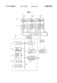
- FIG. 1 is a block diagram showing a video communication terminal apparatus (video transmission-reception apparatus) according to an embodiment of the present invention.
- FIG. 2 is a schematic view illustrating a screen for displaying an image from a video transmission apparatus to which a plurality of cameras are connected.
- FIG. 3 is a block diagram showing a video communication terminal apparatus in which a camera input composer is included.
- FIG. 4 is a schematic view illustrating a screen for displaying an image from the video transmission apparatus in which the camera input composer is included and to which the plurality of cameras are connected.
- FIG. 5 is a schematic view illustrating a screen for displaying a composite image from the video transmission apparatus in which the camera input composer is included and to which the plurality of cameras are connected.
- FIG. 6 is a block diagram showing the configuration of a network according to another embodiment of the present invention.
- FIG. 7 is a block diagram showing the configuration of software according to the embodiment of the present invention.
- FIG. 8 is a plan view illustrating a camera display control panel which is displayed by a monitoring apparatus according to the present invention.
- FIG. 9 is a chart showing a camera icon representing a camera that cannot be controlled.
- FIG. 10 is a chart showing a camera icon representing a plurality of cameras connected to the same host.
- FIG. 11 is a chart showing a camera icon representing a camera connected to the camera input composer.
- FIG. 12 is a plan view illustrating a camera display control panel, including a composite image, which panel is displayed by the monitoring apparatus.
- FIG. 13 is a partially enlarged chart showing part of the composite image shown in FIG. 12.
- a plurality of video communication terminals (substantially computers having the function of video communication) which connect with one camera device or a plurality of camera devices are connected to a computer network. Any of the communication terminals or an exclusive computer displays an image from a selected camera device or images from selected camera devices, and operates each camera device by remote control.
- FIG. 1 shows the schematic block diagram of a typical example of the plurality of video communication terminals which connect with the one camera device or a plurality of camera devices.
- Camera control circuits 12-1 to 12-3 directly control video cameras 10-1 to 10-3 to pan, tilt, zoom, adjust focuses, adjust exposure, and perform other operations, in accordance with external control signals.
- a camera input selector 14 selects which of the video cameras 10-1 to 10-3 to control, in order to take in an output signal from the selected camera (the output signal is normally a video signal, but both a video signal and an audio signal when a microphone-equipped camera is used).
- a communications line for example, RS-232C and so forth are used, however, it is obvious that the present invention is not limited thereto.
- a video communication terminal apparatus (video transmitter-receiver apparatus) 20 sends a control command to a desired camera controller 12-1, 12-2 or 12-3 through the camera input selector 14 to control one of the video cameras 10-1 to 10-3 connected to the selected camera controller.
- This video communication terminal apparatus 20 also transmits a video signal from the selected camera to a network, while it receives a video signal from the network.
- the video communication terminal apparatus 20 includes a central processing unit (CPU) 22 for controlling the whole of the apparatus 20, a main memory 24, a second memory unit 26 (for example, a hard disc unit), a mouse serving as a designating device, and a keyboard 30.
- CPU central processing unit
- An input/output (I/O) port 32 which is connected to the camera input selector 14, supplies it with a camera control command.
- a video board 34 takes in the video signal from the video camera selected by the camera input selector 14, and displays various images on a bit-map display 35.
- a network interface 36 connects the video communication terminal apparatus 20 to a computer network or a communications network. The respective devices, namely, the CPU 22 to the video board 34 and the network interface 36, are mutually connected by a system bus 38.
- the network interface 36 enables the video communication terminal apparatus 20 to control a camera that is connected to a camera controller at a distant place by sending a control signal to the camera through the network, and to receive a camera control signal through the network.
- the camera input selector 14 selects one control signal line and its video output from control signal lines connected to the camera control circuits 12-1 to 12-3 in order to supply the video board 34 with the selected video output, and logically connects the selected control line to the I/O port 32.
- a video signal form for example, the NTSC signal is used.
- the video board 34 takes in a video signal outputted from the camera input selector 14. The video signal taken in is displayed as a moving-image in a predetermined window on the bit-map display 35.
- the video board 34 also has the function of compressing or expanding the video signal.
- the second memory device 26 a variety of information related to the cameras 10-1 to 10-3 and other cameras connected to the apparatus 20 through the network, for example, camera position information data, camera figure data and so forth are stored.
- the camera input selector 14 When the camera input selector 14 is connected to only one of the video cameras 10-1 to 10-3, it does not need to be used.
- the corresponding camera controller 12 may be directly connected to the I/O port 32.
- the camera control circuit 12 When the video camera 10 is a type in which pan, tilt and so forth cannot be controlled, the camera control circuit 12 does not need to be used.
- no video camera when a video camera connected to another video communication terminal is operated by remote control to display only an image from the camera by using the video communication terminal apparatus 20, it is unnecessary to use any of the video cameras 10-1 to 10-3, any of the camera control circuits 12-1 to 12-3 and the camera input selector 14.
- FIG. 2 shows an example of the video display window displayed on the bit-map display 35 when the video communication terminal apparatus 20 is connected to four video cameras.
- buttons camera selecting buttons
- FIG. 2 shows an example of the video display window displayed on the bit-map display 35 when the video communication terminal apparatus 20 is connected to four video cameras.
- buttons camera selecting buttons
- the user can select one specified camera for displaying an image by selecting one button from these buttons on the screen.
- a similar video display window is formed on the screen of another video communication terminal apparatus that receives an image from this video communication terminal apparatus and displays the received image.
- the camera input selector 14 may include a camera selector 14A for selecting a video camera to be controlled and supplying the selected video camera with a camera control signal, and a camera input composer 14B for outputting a composite video signal from all video cameras 10-1 to 10-3 or from a plurality of selected video cameras or for outputting a video signal from one selected camera.
- selecting video cameras to be controlled, and selecting video cameras from which images are inputted to the camera input composer 14B are independent of each other.
- To produce the composite image there are two techniques, spatial composition in which images from a plurality of video cameras are combined on the same screen, and time-bases composition in which images from a plurality of video cameras are repeatedly changed over on a time-axis. In this embodiment both techniques can be selected.
- FIGS. 4 and 5 show examples of the video display screen corresponding to the embodiment shown in FIG. 3.
- FIG. 4 shows a condition of the screen on which an image from a single video camera is displayed
- FIG. 5 shows a condition of the screen on which a composite image of four images from four video cameras is displayed.
- camera selecting buttons and a composing button for switching over the composite image display and the single-image full-screen display are displayed in the bottom right corner of the screen.
- the video communication terminal apparatus shown in FIG. 1 or 3 is connected, as terminals 40, 42 and 44, to a computer network 46, as shown in FIG. 6.
- the terminal 40 which is a monitoring terminal operated by the user as an observer, can control video cameras connected to itself and video cameras connected to the whole terminals 42, 44 connected to the network 46.
- the terminal 40 also can display an image from any camera or images from any cameras. Although one monitoring terminal 40 is used in general, there is no problem if a plurality of monitoring terminals 40 are used.
- Other terminals 42 and 44 are video transmission terminals for transmitting an image or images from one camera (or from a plurality of cameras connected to the terminals) to the monitoring terminals 40.
- the terminal 42 has a structure as shown in FIG. 1 and the terminal 44 has a structure as shown in FIG. 3, it need hardly be said that the number of cameras connected to each terminal may be only one.
- at least one video transmission terminal is used as the video transmission terminals 42 and 44.
- LAN local area network
- WAN wide area network
- Video boards 34 in the monitoring terminal 40, the video transmission terminals 42 and 44 (having the function of video capture) supply video data taken in to bit-map displays 35 to display images.
- a network interface 36 in the monitoring terminal 40 transmits control commands, such as a camera switching command and an image composing command, to the network 46, with the control commands converted into packets. These pieces of information are transmitted to a specified terminal in accordance with the contents of data to be transmitted and the necessity.
- the video transmission terminals 42 and 44 compress video data using their video boards 34 to convert it into packets, and transmit the packet-converted data to the monitoring terminal 40.
- the monitoring terminal 40 expands the received data using its video board 34 to display an image on the bit-map display 35, similar to the processing of its local video signal.
- FIG. 7 is a block diagram showing the configuration of software used in this embodiment.
- a camera managing server 50 In the monitoring terminal 40, a camera managing server 50, a camera control server 52, a camera control client 54, and video reception software 56 are installed, while in the video transmission terminals 42 and 44, camera control servers 52 and video transmission software 58 are installed.
- the camera managing server 50 is software to manage all the cameras, connected to the network 46, which can be utilized by the monitoring terminal 40.
- the camera managing server 50 holds static information related to the respective cameras, such as the names of the respective cameras, the names of hosts (the names of the terminals to which the cameras are connected), the locations at which the respective cameras are installed, whether or not the panning, tilting and zooming of the cameras can be controlled, and dynamic information representing the present condition as to whether or not the cameras are being controlled or images from the cameras are being displayed, and the names of the terminals provided with the function of video composing (for example, the camera input composer 14B).
- the camera managing server 50 also manages the registration of cameras which can be newly available through the network 46, the cancellation of cameras which has been separated from the network 46, and notifies the camera control client 54 of the management information of each camera, periodically or on demand.
- the camera control server 52 is software to control the cameras which belong thereto, being instructed by the camera control client 54.
- the camera control server 52 displays the locations and directions where both the cameras connected to the monitoring terminal 40 and all the available cameras through the network 46 are installed so that predetermined corresponding camera symbols overlap with the map on the display screen of the monitoring terminal 40.
- the camera control client 54 also updates the form of the icon of each camera in real time, based on camera information sent from the camera managing server 50.
- the video transmission software 58 compresses an image taken in the terminal, and transmits the compressed image to a demanding terminal (normally, the monitoring terminal 40).
- the video reception software 56 expands the transmitted, compressed image, and displays it on the bit-map display.
- FIG. 8 shows a camera display control panel that is displayed on the bit-map display 35 of the monitoring terminal 40 by the camera control client 54.
- a map window 60 displays camera icons which represent the locations and directions where the respective cameras are installed so that the icons overlap with a map showing the places where the cameras being controlled are installed.
- a camera display window 62 displays an image from one selected camera or images from a plurality of selected cameras (images from a maximum of six video transmitters), and includes six video display regions 62A, 62B, 62C, 62D, 62E and 62F.
- a camera operation panel 64 is provided with various camera control buttons for operating the selected cameras to pan, tilt and zoom.
- a window display system that can simultaneously display a plurality of windows operates.
- a map that shows the arrangement of seats in an office or store is displayed on the map window 60, and on this map the camera icons 66-1 to 66-12 which correspond to the respective locations of cameras installed in such an office or store are displayed.
- the respective camera icons 66-1 to 66-12 are displayed at the appropriate positions corresponding to the locations of the cameras, almost in the same directions as the cameras are actually directed.
- the cameras corresponding to the camera icons 66-9 and 66-12 cannot be externally controlled, which condition is represented by the form of each icon shown in FIG. 9.
- the camera icon corresponding to a camera from which an image is being displayed on the video display window 62 is displayed by the camera control client 54 so that the frame of the icon is yellow.
- the operation of the camera display control panel shown in FIG. 8 and how the panel is used will be described below.
- the camera control client 54 queries the camera managing server 50 about information related to the camera corresponding to the selected camera icon 66-1.
- the camera managing server 50 makes reference to the name of the camera queried, and confirms whether or not another camera connected to the same host (video transmission terminal apparatus 20) is used.
- the camera managing server 50 looks up whether or not another camera connected to the camera input selector 14 for the same host to which the selected camera is connected is used, and notifies the camera control client 54 of the result.
- the camera managing server 50 simultaneously confirms whether or not the host corresponding to the selected camera is provided with the camera input composer 14B. If the host is provided with the camera input composer 14B, the camera managing server 50 notifies the camera control client 54 of its presence.
- the camera control client 54 changes each form of the camera icons corresponding to all the cameras connected to the same host to which the early selected camera is connected, into a form shown in FIG. 10 when the host is not provided with the camera input composer 14B.
- the camera control client 54 changes each form into a form shown in FIG. 11 when the host is provided with the camera input composer 14B.
- the frames of the camera icons in both cases are changed to be yellowish green. While the image from the camera corresponding to the icon 66-1 is being displayed in one of the video display regions 62A to 62F of the video display window 62, the camera control client 54 also changes the frame color of the video display region to yellowish green.
- the camera control client 54 changes each form of the camera icons 66-1, 66-2, 66-3 and 66-4 into the form shown in FIG. 10, which form has been already shown in FIG. 8, and displays the frames of the changed camera icons in yellowish green. While the image from the camera corresponding to the selected camera icon 66-1 is being displayed in the video display region 62A of the video display window 62, the camera control client 54 displays the frame surrounding the video display region 62A in yellowish green, as shown in FIG. 8.
- FIG. 12 shows an example of the screen obtained when the camera corresponding to the selected camera icon (in this case the icon 66-1) is connected to the host provided with the camera input composer 14B.
- the camera control client 54 changes each form of the camera icons 66-1, 66-2, 66-3 and 66-4 into the form shown in FIG. 11, and displays the changed icon frame in yellowish green.
- the composite image of images from four cameras connected to the host to which the camera corresponding to the camera icon 66-1 is connected is displayed in the video display region 62A of the video display window 62.
- Camera selecting buttons and composing buttons are displayed in the bottom right corner of the video display region 62A.
- the camera control client 54 displays an L-shaped yellowish green frame along the periphery of a portion of the video display region 62A, in which portion the image from the camera corresponding the camera icon 66-1 is displayed.
- An enlarged view of the portion of the video display region 62A is shown in FIG. 13.
- Such displayed camera icons on the map enable the observer to easily grasp which cameras are connected to the same host to which the selected camera is connected.
- the display conditions of the camera icons are different, thus, the observer can easily grasp both a type of cameras by which a composite image of reduced images can be displayed and another type of camera by which a composite image of reduced images cannot be displayed.
- the camera icon corresponding to this camera may be dragged and dropped on the video display window 62.
- the camera control client. 54 queries the camera managing server 50 about whether or not an image from a camera connected to the same host to which the camera represented by the icon 66-2 is being displayed.
- the camera control client 54 sends the host a camera switching command for switching the camera to the camera represented by the camera icon 66-2 so that the host transmits the image from the camera represented by the camera icon 66-2, and then displays the transmitted image from the camera represented by the camera icon 66-2 in the video display region (for example, 62A) where the image from the camera represented by the camera icon 66-1 is displayed.
- the camera control client 54 While the image from the camera connected to the same host is not being displayed, the camera control client 54 displays the image from the camera corresponding to the camera icon 66-2 in the display region where no image is displayed. At this time, the camera control client 54 looks up the host that is provided with the camera corresponding to the camera icon 66-2, and if another camera connected to the host is detected, camera selecting buttons are displayed in the video display region in which the image from the camera corresponding to the camera icon 66-2 are displayed, as shown in FIG. 2.
- the camera control managing server 50 updates the list of the names of the cameras from which images are being displayed, and the camera control client 54 changes the frames of camera icons corresponding to camera names included in the camera name list to be yellow.
- the camera operation panel 64 is displayed.
- a red frame surrounding the region is displayed to represent a camera control condition.
- the color of the camera icon corresponding to the camera being controlled is also changed to red.
- the display forms of the camera icons are changed in accordance with whether or not the cameras are controlled, whether or not the cameras are connected to the same host (video communication terminal apparatus 20), and whether or not the cameras are connected to the same camera input composer.
- the brightness of the camera icons corresponding to cameras which cannot be controlled may be changed such that the colors of the camera icons are darkened, or the display colors of the camera icons are differentiated.
- the camera icons corresponding to cameras from which images are displayed are discriminated based on their frame colors, the forms of the camera icons may be changed.
- the camera icons may be modified by combining colors and forms so that the observer can easily discriminate the icons.
- the present invention may be applied to a system formed by a plurality of apparatuses or an apparatus formed by a single unit.
- the present invention may be applied by providing a system or apparatus with software.
- a storage medium in which software for using the present invention is stored is a main component of the present invention.
- the system or apparatus operates in a predetermined manner by the software read from the storage medium thereto.
- the camera icons displayed on the map enable the observer to easily grasp the relationship between the cameras represented by the camera icons and the images being displayed on the video display screen.
- the cameras which can be externally controlled to pan, tilt and zoom, and the cameras which cannot be externally controlled are discriminated by using the camera icons.
- the camera icons on the map enable the observer to recognize which camera is connected to the same video transmission apparatus to which the selected camera is connected, and to recognize which cameras are connected to the same camera input composer. Accordingly, the operability of the system is extremely improved.
- camera information can be displayed by using the camera icons on the map so that the observer can easily understand the information.
Abstract
Apparatus and method for displaying control information of a plurality of cameras connected to a network includes structure and steps for: displaying a map showing locations at which the plurality of cameras are disposed; and displaying symbols representing the cameras in accordance with the locations at which the cameras are disposed so that the symbols overlap with the displayed map, while displaying symbols in different forms in accordance with different conditions of the cameras.
Description
1. Field of the Invention
This invention relates to a control system for cameras connected to a network.
2. Description of the Related Art
There is a known camera control system capable of operating one monitoring camera or a plurality of monitoring cameras by remote control from a distant place. Such monitoring cameras vary from a type in which a camera is fixed on a table so as to be always directed in one direction to a type in which a camera can pan, tilt, and zoom by external control. The latter commonly includes the function of changing both the direction of photographing and magnification by remote control from a monitoring center.
When a plurality of cameras are operated by remote control, where and in which direction the respective cameras are installed need to be indicated to the operator. For example, for a monitoring system in which many cameras are installed in a store, a factory or a building, a camera information display system has been proposed. In such a camera information display system, figures representing the cameras are displayed at the appropriate positions in accordance with the respective cameras so that the figures overlap with an installation position map.
According to the camera information display system, the user as an observer can visually understand the location of the camera being operated. However, the above system hardly provides the user with sufficient displayed camera information.
For example, although the user can recognize the location(s) of the camera(s) being controlled on the map, the user cannot easily understand from which camera one image on the display screen is sent or from which cameras a plurality of images on the display screen are sent, based on the displayed information on the map.
In addition, in the above system the user cannot easily recognize on the map whether or not the camera(s) can be externally controlled with respect to photographing conditions such as panning, tilting and zooming.
Further, conventionally, one communication terminal is connected to at least one camera, and an image taken by a selected camera is transmitted, or images (or a composite image) taken by selected cameras are transmitted, to the monitoring controller of a monitoring center through a computer network. The above system has no means for using the map to recognize whether the cameras are connected to the same communication terminal. For example, in connection with switching over cameras connected to the same communication terminal, if the user can utilize a video display window that is assigned to the communication terminal without changing the window, troublesome or time-consuming operations (such as switching over the video display window to another window or creating a new window) can be eliminated because the user immediately understands whether or not a desired image can be obtained from a different camera connected to the same communication terminal. Accordingly, the user would experience improved operability.
Accordingly, it is an object of the present invention to provide a camera information display apparatus that satisfies these issues or demands.
In other words, it is another object of the present invention to provide a camera information display apparatus by which a displayed image or images and the relationship thereof to a camera or cameras as the origin can be readily recognized.
It is a further object of the present invention to provide a camera information display apparatus by which whether each camera can be externally controlled can be recognized.
It is a still further object of the present invention to provide a camera information display apparatus by which a camera or cameras connected to the same communication terminal can be easily recognized.
In accordance with an aspect of the present invention, the foregoing objects are achieved through the provision of a system for controlling a plurality of cameras connected to a network and for displaying an image from the camera or images from the cameras, the system including: map display means for displaying the locations at which the cameras are installed; symbol display means for displaying symbols representing the respective cameras in accordance with the locations at which the cameras are installed so that the symbols overlap with the map displayed by the map display means; and control means for controlling the symbol display means to display the symbols so as to be in different conditions in accordance with the conditions of the cameras corresponding to the symbols.
In accordance with another aspect of the present invention, the foregoing objects are achieved through the provision of a method for assisting control of a plurality of cameras connected to a network, comprising the steps of: displaying the locations at which the plurality of cameras are installed; and displaying symbols representing the respective cameras in accordance with the locations at which the cameras are installed so that the symbols overlap with the map displayed by map display means, while displaying the symbols in different conditions in accordance with the conditions of the cameras.
In accordance with a further aspect of the present invention, the foregoing objects are achieved through the provision of a medium in which programs for controlling a plurality of cameras connected to a network are recorded, the programs being used for displaying the locations at which the plurality of cameras are installed, and for displaying symbols representing the respective cameras in accordance with the locations at which the cameras are installed so that the symbols overlap with the map displayed by map display means, and for displaying the symbols in different conditions in accordance with the conditions of the cameras corresponding to the symbols.
Other objects and features of the present invention will be apparent from the following description and the attached drawings.
FIG. 1 is a block diagram showing a video communication terminal apparatus (video transmission-reception apparatus) according to an embodiment of the present invention.
FIG. 2 is a schematic view illustrating a screen for displaying an image from a video transmission apparatus to which a plurality of cameras are connected.
FIG. 3 is a block diagram showing a video communication terminal apparatus in which a camera input composer is included.
FIG. 4 is a schematic view illustrating a screen for displaying an image from the video transmission apparatus in which the camera input composer is included and to which the plurality of cameras are connected.
FIG. 5 is a schematic view illustrating a screen for displaying a composite image from the video transmission apparatus in which the camera input composer is included and to which the plurality of cameras are connected.
FIG. 6 is a block diagram showing the configuration of a network according to another embodiment of the present invention.
FIG. 7 is a block diagram showing the configuration of software according to the embodiment of the present invention.
FIG. 8 is a plan view illustrating a camera display control panel which is displayed by a monitoring apparatus according to the present invention.
FIG. 9 is a chart showing a camera icon representing a camera that cannot be controlled.
FIG. 10 is a chart showing a camera icon representing a plurality of cameras connected to the same host.
FIG. 11 is a chart showing a camera icon representing a camera connected to the camera input composer.
FIG. 12 is a plan view illustrating a camera display control panel, including a composite image, which panel is displayed by the monitoring apparatus.
FIG. 13 is a partially enlarged chart showing part of the composite image shown in FIG. 12.
By referring to the attached drawings, embodiments of the present invention will be described below.
In accordance with an embodiment of the present invention, a plurality of video communication terminals (substantially computers having the function of video communication) which connect with one camera device or a plurality of camera devices are connected to a computer network. Any of the communication terminals or an exclusive computer displays an image from a selected camera device or images from selected camera devices, and operates each camera device by remote control. FIG. 1 shows the schematic block diagram of a typical example of the plurality of video communication terminals which connect with the one camera device or a plurality of camera devices.
Camera control circuits 12-1 to 12-3 directly control video cameras 10-1 to 10-3 to pan, tilt, zoom, adjust focuses, adjust exposure, and perform other operations, in accordance with external control signals. A camera input selector 14 selects which of the video cameras 10-1 to 10-3 to control, in order to take in an output signal from the selected camera (the output signal is normally a video signal, but both a video signal and an audio signal when a microphone-equipped camera is used). As a communications line, for example, RS-232C and so forth are used, however, it is obvious that the present invention is not limited thereto.
A video communication terminal apparatus (video transmitter-receiver apparatus) 20 sends a control command to a desired camera controller 12-1, 12-2 or 12-3 through the camera input selector 14 to control one of the video cameras 10-1 to 10-3 connected to the selected camera controller. This video communication terminal apparatus 20 also transmits a video signal from the selected camera to a network, while it receives a video signal from the network. The video communication terminal apparatus 20 includes a central processing unit (CPU) 22 for controlling the whole of the apparatus 20, a main memory 24, a second memory unit 26 (for example, a hard disc unit), a mouse serving as a designating device, and a keyboard 30.
An input/output (I/O) port 32, which is connected to the camera input selector 14, supplies it with a camera control command. A video board 34 takes in the video signal from the video camera selected by the camera input selector 14, and displays various images on a bit-map display 35. A network interface 36 connects the video communication terminal apparatus 20 to a computer network or a communications network. The respective devices, namely, the CPU 22 to the video board 34 and the network interface 36, are mutually connected by a system bus 38. The network interface 36 enables the video communication terminal apparatus 20 to control a camera that is connected to a camera controller at a distant place by sending a control signal to the camera through the network, and to receive a camera control signal through the network.
The camera input selector 14 selects one control signal line and its video output from control signal lines connected to the camera control circuits 12-1 to 12-3 in order to supply the video board 34 with the selected video output, and logically connects the selected control line to the I/O port 32. As a video signal form, for example, the NTSC signal is used. The video board 34 takes in a video signal outputted from the camera input selector 14. The video signal taken in is displayed as a moving-image in a predetermined window on the bit-map display 35. The video board 34 also has the function of compressing or expanding the video signal.
In the second memory device 26, a variety of information related to the cameras 10-1 to 10-3 and other cameras connected to the apparatus 20 through the network, for example, camera position information data, camera figure data and so forth are stored.
When the camera input selector 14 is connected to only one of the video cameras 10-1 to 10-3, it does not need to be used. The corresponding camera controller 12 may be directly connected to the I/O port 32. When the video camera 10 is a type in which pan, tilt and so forth cannot be controlled, the camera control circuit 12 does not need to be used. When no video camera is used, in other words, when a video camera connected to another video communication terminal is operated by remote control to display only an image from the camera by using the video communication terminal apparatus 20, it is unnecessary to use any of the video cameras 10-1 to 10-3, any of the camera control circuits 12-1 to 12-3 and the camera input selector 14.
FIG. 2 shows an example of the video display window displayed on the bit-map display 35 when the video communication terminal apparatus 20 is connected to four video cameras. In the bottom right corner of the display screen, buttons (camera selecting buttons) for selecting the cameras which output images to be displayed within the display screen are displayed in a small size. The user can select one specified camera for displaying an image by selecting one button from these buttons on the screen. A similar video display window is formed on the screen of another video communication terminal apparatus that receives an image from this video communication terminal apparatus and displays the received image. By operating camera selecting buttons on the screen at the receiving side, any of the video cameras connected to the transmitter's video communication terminal can be selected and its output image can be displayed on the screen of the receiver's video communication terminal apparatus.
As shown in FIG. 3, the camera input selector 14 may include a camera selector 14A for selecting a video camera to be controlled and supplying the selected video camera with a camera control signal, and a camera input composer 14B for outputting a composite video signal from all video cameras 10-1 to 10-3 or from a plurality of selected video cameras or for outputting a video signal from one selected camera. In such a case, selecting video cameras to be controlled, and selecting video cameras from which images are inputted to the camera input composer 14B are independent of each other. To produce the composite image, there are two techniques, spatial composition in which images from a plurality of video cameras are combined on the same screen, and time-bases composition in which images from a plurality of video cameras are repeatedly changed over on a time-axis. In this embodiment both techniques can be selected.
FIGS. 4 and 5 show examples of the video display screen corresponding to the embodiment shown in FIG. 3. FIG. 4 shows a condition of the screen on which an image from a single video camera is displayed, while FIG. 5 shows a condition of the screen on which a composite image of four images from four video cameras is displayed. In each condition, camera selecting buttons and a composing button for switching over the composite image display and the single-image full-screen display are displayed in the bottom right corner of the screen.
The video communication terminal apparatus shown in FIG. 1 or 3 is connected, as terminals 40, 42 and 44, to a computer network 46, as shown in FIG. 6. The terminal 40, which is a monitoring terminal operated by the user as an observer, can control video cameras connected to itself and video cameras connected to the whole terminals 42, 44 connected to the network 46. The terminal 40 also can display an image from any camera or images from any cameras. Although one monitoring terminal 40 is used in general, there is no problem if a plurality of monitoring terminals 40 are used.
As the network 46, a local area network (LAN) or wide area network (WAN) that has a sufficient transmission bandwidth for transmitting both digital moving-image data and a camera control signal may be used. Such moving-image data may be transmitted with the data compressed. Since a variety of known methods can be utilized in this embodiment, a detailed description thereof will be omitted.
On receiving the packet-converted video data from the video transmission terminal 42 or 44, the monitoring terminal 40 expands the received data using its video board 34 to display an image on the bit-map display 35, similar to the processing of its local video signal.
FIG. 7 is a block diagram showing the configuration of software used in this embodiment. In the monitoring terminal 40, a camera managing server 50, a camera control server 52, a camera control client 54, and video reception software 56 are installed, while in the video transmission terminals 42 and 44, camera control servers 52 and video transmission software 58 are installed.
The camera managing server 50 is software to manage all the cameras, connected to the network 46, which can be utilized by the monitoring terminal 40. The camera managing server 50 holds static information related to the respective cameras, such as the names of the respective cameras, the names of hosts (the names of the terminals to which the cameras are connected), the locations at which the respective cameras are installed, whether or not the panning, tilting and zooming of the cameras can be controlled, and dynamic information representing the present condition as to whether or not the cameras are being controlled or images from the cameras are being displayed, and the names of the terminals provided with the function of video composing (for example, the camera input composer 14B). The camera managing server 50 also manages the registration of cameras which can be newly available through the network 46, the cancellation of cameras which has been separated from the network 46, and notifies the camera control client 54 of the management information of each camera, periodically or on demand.
The camera control server 52 is software to control the cameras which belong thereto, being instructed by the camera control client 54. The camera control server 52 displays the locations and directions where both the cameras connected to the monitoring terminal 40 and all the available cameras through the network 46 are installed so that predetermined corresponding camera symbols overlap with the map on the display screen of the monitoring terminal 40. The camera control client 54 also updates the form of the icon of each camera in real time, based on camera information sent from the camera managing server 50.
The video transmission software 58 compresses an image taken in the terminal, and transmits the compressed image to a demanding terminal (normally, the monitoring terminal 40). The video reception software 56 expands the transmitted, compressed image, and displays it on the bit-map display.
FIG. 8 shows a camera display control panel that is displayed on the bit-map display 35 of the monitoring terminal 40 by the camera control client 54. A map window 60 displays camera icons which represent the locations and directions where the respective cameras are installed so that the icons overlap with a map showing the places where the cameras being controlled are installed. A camera display window 62 displays an image from one selected camera or images from a plurality of selected cameras (images from a maximum of six video transmitters), and includes six video display regions 62A, 62B, 62C, 62D, 62E and 62F. A camera operation panel 64 is provided with various camera control buttons for operating the selected cameras to pan, tilt and zoom. On the bit-map display 35 of the monitoring terminal 40, a window display system that can simultaneously display a plurality of windows operates.
A map that shows the arrangement of seats in an office or store is displayed on the map window 60, and on this map the camera icons 66-1 to 66-12 which correspond to the respective locations of cameras installed in such an office or store are displayed. The respective camera icons 66-1 to 66-12 are displayed at the appropriate positions corresponding to the locations of the cameras, almost in the same directions as the cameras are actually directed. The cameras corresponding to the camera icons 66-9 and 66-12 cannot be externally controlled, which condition is represented by the form of each icon shown in FIG. 9. The camera icon corresponding to a camera from which an image is being displayed on the video display window 62 is displayed by the camera control client 54 so that the frame of the icon is yellow.
The operation of the camera display control panel shown in FIG. 8 and how the panel is used will be described below. By selecting one icon from the camera icons 66-1 to 66-12 on the map window 60 (for example, by clicking the icon 66-1 with a mouse), the camera corresponding to the selected icon is regarded as selected, and the frame color of the icon 661 is changed to yellowish green by the camera control client 54. The camera control client 54 queries the camera managing server 50 about information related to the camera corresponding to the selected camera icon 66-1. The camera managing server 50 makes reference to the name of the camera queried, and confirms whether or not another camera connected to the same host (video transmission terminal apparatus 20) is used. In other words, the camera managing server 50 looks up whether or not another camera connected to the camera input selector 14 for the same host to which the selected camera is connected is used, and notifies the camera control client 54 of the result. The camera managing server 50 simultaneously confirms whether or not the host corresponding to the selected camera is provided with the camera input composer 14B. If the host is provided with the camera input composer 14B, the camera managing server 50 notifies the camera control client 54 of its presence.
The camera control client 54 changes each form of the camera icons corresponding to all the cameras connected to the same host to which the early selected camera is connected, into a form shown in FIG. 10 when the host is not provided with the camera input composer 14B. The camera control client 54 changes each form into a form shown in FIG. 11 when the host is provided with the camera input composer 14B. The frames of the camera icons in both cases are changed to be yellowish green. While the image from the camera corresponding to the icon 66-1 is being displayed in one of the video display regions 62A to 62F of the video display window 62, the camera control client 54 also changes the frame color of the video display region to yellowish green.
For example, when the cameras corresponding to the camera icons 66-1, 66-2, 66-3 and 66-4 are connected to the same host which is not provided with the camera input composer 14B, the camera control client 54 changes each form of the camera icons 66-1, 66-2, 66-3 and 66-4 into the form shown in FIG. 10, which form has been already shown in FIG. 8, and displays the frames of the changed camera icons in yellowish green. While the image from the camera corresponding to the selected camera icon 66-1 is being displayed in the video display region 62A of the video display window 62, the camera control client 54 displays the frame surrounding the video display region 62A in yellowish green, as shown in FIG. 8.
FIG. 12 shows an example of the screen obtained when the camera corresponding to the selected camera icon (in this case the icon 66-1) is connected to the host provided with the camera input composer 14B. The camera control client 54 changes each form of the camera icons 66-1, 66-2, 66-3 and 66-4 into the form shown in FIG. 11, and displays the changed icon frame in yellowish green. As shown in FIG. 12, the composite image of images from four cameras connected to the host to which the camera corresponding to the camera icon 66-1 is connected is displayed in the video display region 62A of the video display window 62. Camera selecting buttons and composing buttons (as shown in FIGS. 4 and 5) are displayed in the bottom right corner of the video display region 62A. In accordance with the selection of the camera icon 66-1, the camera control client 54 displays an L-shaped yellowish green frame along the periphery of a portion of the video display region 62A, in which portion the image from the camera corresponding the camera icon 66-1 is displayed. An enlarged view of the portion of the video display region 62A is shown in FIG. 13.
Such displayed camera icons on the map enable the observer to easily grasp which cameras are connected to the same host to which the selected camera is connected. In addition, when the host is provided with the camera input composer, the display conditions of the camera icons are different, thus, the observer can easily grasp both a type of cameras by which a composite image of reduced images can be displayed and another type of camera by which a composite image of reduced images cannot be displayed.
In order to select a camera from which an image needs to be displayed on the video display window 62, the camera icon corresponding to this camera may be dragged and dropped on the video display window 62. For example, when the selected camera is represented by the camera icon 66-2, the camera control client. 54 queries the camera managing server 50 about whether or not an image from a camera connected to the same host to which the camera represented by the icon 66-2 is being displayed.
If an image from a camera connected to the same host is being displayed, for example, while the image from the camera represented by the camera icon 66-1 is being displayed, the camera control client 54 sends the host a camera switching command for switching the camera to the camera represented by the camera icon 66-2 so that the host transmits the image from the camera represented by the camera icon 66-2, and then displays the transmitted image from the camera represented by the camera icon 66-2 in the video display region (for example, 62A) where the image from the camera represented by the camera icon 66-1 is displayed.
While the image from the camera connected to the same host is not being displayed, the camera control client 54 displays the image from the camera corresponding to the camera icon 66-2 in the display region where no image is displayed. At this time, the camera control client 54 looks up the host that is provided with the camera corresponding to the camera icon 66-2, and if another camera connected to the host is detected, camera selecting buttons are displayed in the video display region in which the image from the camera corresponding to the camera icon 66-2 are displayed, as shown in FIG. 2.
When an image is further displayed among the video display regions 62A to 62F of the video display window 62, or when a camera from which an image is being displayed has been switched to another camera, the camera control managing server 50 updates the list of the names of the cameras from which images are being displayed, and the camera control client 54 changes the frames of camera icons corresponding to camera names included in the camera name list to be yellow.
By selecting one image from the images displayed in the video display regions 62A to 62F of the video display window 62 (for example, by clicking with the mouse), or by double clicking any camera icon on the map window 60, the camera operation panel 64 is displayed. With respect to each of the video display regions 62A to 62F for displaying an image from the camera corresponding to the activated camera operation panel, a red frame surrounding the region is displayed to represent a camera control condition. The color of the camera icon corresponding to the camera being controlled is also changed to red.
In the foregoing embodiments the display forms of the camera icons are changed in accordance with whether or not the cameras are controlled, whether or not the cameras are connected to the same host (video communication terminal apparatus 20), and whether or not the cameras are connected to the same camera input composer. However, for example, the brightness of the camera icons corresponding to cameras which cannot be controlled may be changed such that the colors of the camera icons are darkened, or the display colors of the camera icons are differentiated. Similarly, although the camera icons corresponding to cameras from which images are displayed are discriminated based on their frame colors, the forms of the camera icons may be changed. The camera icons may be modified by combining colors and forms so that the observer can easily discriminate the icons.
Further, it is obvious that the present invention may be applied to a system formed by a plurality of apparatuses or an apparatus formed by a single unit. In addition, the present invention may be applied by providing a system or apparatus with software. In such a case a storage medium in which software for using the present invention is stored is a main component of the present invention. The system or apparatus operates in a predetermined manner by the software read from the storage medium thereto.
As easily understood from the foregoing description, in accordance with the above embodiments, the camera icons displayed on the map enable the observer to easily grasp the relationship between the cameras represented by the camera icons and the images being displayed on the video display screen.
In addition, the cameras which can be externally controlled to pan, tilt and zoom, and the cameras which cannot be externally controlled are discriminated by using the camera icons.
Further, the camera icons on the map enable the observer to recognize which camera is connected to the same video transmission apparatus to which the selected camera is connected, and to recognize which cameras are connected to the same camera input composer. Accordingly, the operability of the system is extremely improved.
As described above, in accordance with the above embodiments, camera information can be displayed by using the camera icons on the map so that the observer can easily understand the information.
The individual components shown in outline are designated by blocks in the Drawings are all well-known in the camera control arts, and their specific construction and operation are not critical to the operation or best mode for carrying out the invention.
While the present invention has been described with respect to what is presently considered to be the preferred embodiments, it is to be understood that the invention is not limited to the disclosed embodiments. To the contrary, the invention is intended to cover various modifications and equivalent arrangements included within the spirit and scope of the appended claims. The scope of the following claims is to be accorded the broadest interpretation so as to encompass all such modifications and equivalent structures and functions.
Claims (35)
1. A system for controlling a plurality of cameras connected to a network, and for displaying images from said plurality of cameras, said system including:
map display means for displaying locations at which said plurality of cameras are disposed;
symbol display means for displaying symbols representing said plurality of cameras in accordance with the locations at which said plurality of cameras are disposed so that said symbols overlap the map displayed by said map display means;
image display means for displaying each of the images from the plurality of cameras on the screen on which said map is displayed;
camera selecting means for selecting a camera to control at least one of panning, tilting, and zooming by designating a desired image from the images displayed by said image display means; and
control means for controlling a display of, in distinguishable forms, (i) a symbol corresponding to the camera to be controlled and selected by said camera selecting means and (ii) another symbol corresponding to another camera, and for controlling a display of, in distinguishable forms, (iii) an image from the camera to be controlled and selected by said camera selecting means and (iv) an image from the another camera.
2. A system according to claim 1, wherein said control means controls said symbol display means to display said symbols in different forms in accordance with whether or not said plurality of cameras are connected to a video transmission terminal which transmits the images selectively from said plurality of images.
3. A system according to claim 1, wherein said control means controls said symbol display means to display said symbols in different forms in accordance with whether or not said plurality of cameras are connected to a video transmission terminal which includes a camera input composing means which composes images from a plurality of cameras.
4. A system according to claim 1, wherein said control means controls said symbol display means to display said symbols in different forms in accordance with whether or not said cameras are externally controllable.
5. A system according to claim 1, wherein said control means controls said symbol display means to display (i) first symbols representing cameras from which images are displayed and (ii) second symbols representing cameras from which images are not displayed, said first and second symbols having different forms.
6. A system according to claim 1, wherein said control means changes colors of said symbols so that said symbols are displayed in said different forms.
7. A system according to claim 1, wherein said control means changes brightness of said symbols so that said symbols are displayed in said different forms.
8. A system according to claim 1, wherein said control means changes the shapes of said symbols so that said symbols are displayed in said different forms.
9. A method for controlling a plurality of cameras connected to a network, comprising the steps of:
displaying a map showing locations at which said plurality of cameras are disposed;
displaying said symbols representing said plurality of cameras in accordance with the locations at which said plurality of cameras are disposed so that said symbols overlap the map displayed by the map displaying step, and displaying said symbols in different forms in accordance with different conditions of said plurality of cameras;
displaying each of the images from the plurality of cameras on the screen on which said map is displayed;
selecting a camera to control at least one of panning, tilting and zooming by designating a desired image from the images displayed; and
controlling a display of, in distinguishable forms, (i) a symbol corresponding to the camera to be controlled and selected by said camera selecting means and (ii) another symbol corresponding to another camera, and for controlling a display of, in distinguishable forms, (iii) an image from the camera to be controlled and selected by said selecting step and (iv) an image from the another camera.
10. A method according to claim 9, wherein said symbols displaying step displays the symbols in different forms in accordance with whether or not said plurality of cameras are connected to a video transmission terminal which transmits the images selectively from the plurality of images.
11. A method according to claim 9, wherein said symbols displaying step displays the symbols in different forms in accordance with whether or not the plurality of cameras are connected to a video transmission terminal which includes a camera input composing means which composes images from a plurality of cameras.
12. A method according to claim 9, wherein said symbols displaying step displays the symbols in different forms in accordance with whether or not said cameras are externally controllable.
13. A method according to claim 9, wherein said symbols displaying step displays (i) first symbols representing cameras from which images are displayed and (ii) second symbols from which images are not displayed are displayed, said first and second symbols having different forms.
14. A method according to claim 9, wherein the symbol displaying step displays symbols of different colors so that said symbols are displayed in said different forms.
15. A method according to claim 9, wherein the symbol displaying step displays symbols of different brightness so that said symbols are displayed in said different forms.
16. A method according to claim 9, wherein the symbol displaying step displays symbols of different shape so that said symbols are displayed in said different forms.
17. A computer-readable medium for storing programs to control a plurality of cameras connected to a network, said programs causing a computer to generate a display map showing (i) locations at which said plurality of cameras are disposed and (ii) symbols representing said plurality of cameras in accordance with the locations in which said plurality of cameras are disposed so that said symbols overlap the display map, said programs causing the computer to generate the display map to display said symbols in different forms in accordance with different conditions of said cameras, said programs causing the computer to perform the functions of:
displaying each of the images from the plurality of cameras on the screen on which said map is displayed;
selecting a camera to control at least one of panning, tilting, and zooming by designating a desired image from the images displayed by the image display step; and
controlling a display of, in distinguishable forms, (i) a symbol corresponding to the camera to be controlled and selected by the camera selecting step and (ii) another symbol corresponding to another camera, and for controlling a display of, in distinguishable forms, (iii) an image from the camera to be controlled and selected by said selecting step and (iv) an image from the another camera.
18. A system according to claim 1, wherein said control means controls said symbol display means to display said symbols in different forms in accordance with whether one or a plurality of cameras are connected to a video transmission terminal.
19. A method according to claim 9, further comprising the step of displaying said symbols in different forms in accordance with whether one or a plurality of cameras are connected to a video transmission terminal.
20. A system for controlling a plurality of cameras connected to a network, and for displaying images from said plurality of cameras, said system including:
map display means for displaying locations at which said plurality of cameras are disposed;
symbol display means for displaying symbols representing said plurality of cameras in accordance with the locations at which said plurality of cameras are disposed so that said symbols overlap the map displayed by said map display means; and
control means for controlling said symbol display means to display a first camera symbol in a first form when a corresponding first one of the plurality of cameras is coupled to a first host, and to display a second camera symbol in a second, different form when a corresponding second one of the plurality of cameras is not coupled to the first host.
21. A system according to claim 20, wherein said control means controls said symbol display means to display said symbols in different forms in accordance with whether or not a camera input composing means is connected to a video transmission terminal to which said cameras are connected.
22. A system according to claim 20, wherein said control means changes colors of said symbols so that said symbols are displayed in said different forms.
23. A system according to claim 20, wherein said control means changes brightness of said symbols so that said symbols are displayed in said different forms.
24. A method for controlling a plurality of cameras connected to a network, and for displaying images from said plurality of cameras, including the steps of:
a map display step for displaying locations at which said plurality of cameras are disposed;
a symbol display step for displaying symbols representing said plurality of cameras in accordance with the locations at which said plurality of cameras are disposed so that said symbols overlap the map displayed by said map display step; and
a control step for controlling said symbol display step to display a first camera symbol in a first form when a corresponding first one of the plurality of cameras is coupled to a first host, and to display a second camera symbol in a second, different form when a corresponding second one of the plurality of cameras is not coupled to the first host.
25. A method according to claim 20, wherein said control step controls said symbol display step to display said symbols in different forms in accordance with whether or not a camera input composing means is connected to a video transmission terminal to which said cameras are connected.
26. A method according to claim 20, wherein said control step changes colors of said symbols so that said symbols are displayed in said different forms.
27. A method according to claim 20, wherein said control step changes brightness of said symbols so that said symbols are displayed in said different forms.
28. A method according to claim 20, wherein said control step changes the shapes of said symbols so that said symbols are displayed in said different forms.
29. A computer readable medium storing a program which controls a plurality of cameras connected to a network, and causes images from said plurality of cameras to be displayed, said program causing the following functions to be performed:
a map display function for displaying locations at which said plurality of cameras are disposed;
a symbol display function for displaying symbols representing said plurality of cameras in accordance with the locations at which said plurality of cameras are disposed so that said symbols overlap the map displayed by said map display means; and
a control function for controlling said symbol display means to display a first camera symbol in a first form when a corresponding first one of said plurality of cameras is coupled to a first host, and to display a second camera symbol in a second, different form when a corresponding second one of the plurality of cameras is not coupled to the first host.
30. A system for controlling plurality of cameras connected to a network, and for displaying images from said plurality of cameras, said system including:
map display means for displaying on a map locations at which said plurality of cameras are disposed;
symbol display means for displaying symbols representing said plurality of cameras in accordance with the locations at which said plurality of cameras are disposed so that said symbols overlap the map displayed by said map display means;
image display means for displaying each of the images from the plurality of cameras on the screen on which said map is displayed;
camera selecting means for selecting a camera to control at least one of panning, tilting, and zooming by designating a symbol on the map;
control means for displaying, in distinguishable forms, (i) an image from the camera to be controlled and selected by said camera selecting means and (ii) an image from another camera, and for displaying, in distinguishable forms, (iii) a symbol corresponding to the camera to be controlled and selected by said camera selecting means, and (iv) another symbol corresponding to the another camera.
31. A system for controlling plurality of cameras connected to a network, and for displaying images from said plurality of cameras, said system including:
a map display step for displaying on a map locations at which said plurality of cameras are disposed;
a symbol display step for displaying symbols representing said plurality of cameras in accordance with the locations at which said plurality of cameras are disposed so that said symbols overlap the map displayed by said map display step;
an image display step for displaying each of the images from the plurality of cameras on the screen on which said map is displayed;
a camera selecting step for selecting a camera to control at least one of panning, tilting, and zooming by designating a symbol on the map;
a control step for displaying, in distinguishable forms, (i) an image from the camera to be controlled and selected by said camera selecting step and (ii) an image from another camera, and for displaying, in distinguishable forms, (iii) a symbol corresponding to the camera to be controlled and selected by said camera selecting step, and (iv) another symbol corresponding to the another camera.
32. A computer-readable medium for storing programs to control a plurality of cameras connected to a network, said programs causing at least one computer to perform the steps of:
a map display, step for displaying on a map locations at which said plurality of cameras are disposed;
a symbol display step for displaying symbols representing said plurality of cameras in accordance with the locations at which said plurality of cameras are disposed so that said symbols overlap the map displayed by said map display step;
an image display step for displaying each of the images from the plurality of cameras on the screen on which said map is displayed;
a camera selecting step for selecting a camera to control at least one of panning, tilting, and zooming by designating a symbol on the map;
a control step for displaying, in distinguishable forms, (i) an image from the camera to be controlled and selected by said camera selecting step and (ii) an image from another camera, and for displaying, in distinguishable forms, (iii) a symbol corresponding to the camera to be controlled and selected by said camera selecting step and (iv) another symbol corresponding to the another camera.
33. A system for controlling a plurality of cameras connected to a network, and for displaying images from said cameras, said system including:
map display means for displaying locations at which said plurality of cameras are disposed;
symbol display means for displaying symbols representing said plurality of cameras in accordance with the locations at which said plurality of cameras are disposed so that said symbols overlap the map displayed by said map display means;
image display means for displaying each of the images from the plurality of cameras on the screen on which said map is displayed;
camera selecting means for selecting a camera to control at least one of panning, tilting, and zooming; and
control means for controlling a display of, in distinguishable forms, (i) a symbol corresponding to the camera to be controlled and selected by said camera selecting means and (ii) another symbol corresponding to another camera, and for controlling a display of, in distinguishable forms, (iii) an image from the camera to be controlled and selected by said camera selecting means and (iv) an image from the another camera.
34. A method for controlling a plurality of cameras connected to a network, comprising the steps of:
displaying a map showing locations at which said plurality of cameras are disposed;
displaying said symbols representing said plurality of cameras in accordance with the locations at which said plurality of cameras are disposed so that said symbols overlap the map displayed by the map displaying step, and displaying said symbols in different forms in accordance with different conditions of said cameras;
displaying each of the images from the plurality of cameras on the screen on which said map is displayed;
selecting a camera to control at least one of panning, tilting and zooming; and
control means for controlling a display of, in distinguishable forms, (i) a symbol corresponding to the camera to be controlled and selected by said camera selecting means and (ii) another symbol corresponding to another camera, and for controlling a display of, in distinguishable forms, (iii) an image from the camera to be controlled and selected by said camera selecting step and (iv) an image from the another camera.
35. A computer-readable medium for storing programs to control a plurality of cameras connected to a network, said programs causing a computer to generate a display map showing (i) locations at which said plurality of cameras are disposed and (ii) symbols representing said plurality of cameras in accordance with the locations in which said plurality of cameras are disposed so that said symbols overlap the display map, said programs causing the computer to generate the display map to display said symbols in different forms in accordance with different conditions of said plurality of cameras, said programs causing the computer to perform the functions of:
displaying each of the images from the plurality of cameras on the screen on which said map is displayed;
selecting a camera to control at least one of panning, tilting, and zooming; and
controlling a display of, in distinguishable forms, (i) a symbol corresponding to the camera to be controlled and selected by the camera selecting step and (ii) another symbol corresponding to another camera, and controlling a display of, in distinguishable forms, (iii) an image from the camera to be controlled and selected by said camera selecting step and (iv) an image from the another camera.
Applications Claiming Priority (2)
| Application Number | Priority Date | Filing Date | Title |
|---|---|---|---|
| JP33086995 | 1995-12-19 | ||
| JP7-330869 | 1995-12-19 |
Publications (1)
| Publication Number | Publication Date |
|---|---|
| US6002995A true US6002995A (en) | 1999-12-14 |
Family
ID=18237433
Family Applications (1)
| Application Number | Title | Priority Date | Filing Date |
|---|---|---|---|
| US08/766,107 Expired - Lifetime US6002995A (en) | 1995-12-19 | 1996-12-16 | Apparatus and method for displaying control information of cameras connected to a network |
Country Status (1)
| Country | Link |
|---|---|
| US (1) | US6002995A (en) |
Cited By (107)
| Publication number | Priority date | Publication date | Assignee | Title |
|---|---|---|---|---|
| US6208379B1 (en) * | 1996-02-20 | 2001-03-27 | Canon Kabushiki Kaisha | Camera display control and monitoring system |
| WO2001069405A1 (en) * | 2000-03-14 | 2001-09-20 | Joseph Robert Marchese | Digital video system using networked cameras |
| US6359647B1 (en) * | 1998-08-07 | 2002-03-19 | Philips Electronics North America Corporation | Automated camera handoff system for figure tracking in a multiple camera system |
| US6392693B1 (en) * | 1998-09-03 | 2002-05-21 | Matsushita Electric Industrial Co., Ltd. | Monitoring video camera apparatus |
| US20020061134A1 (en) * | 2000-11-17 | 2002-05-23 | Honeywell International Inc. | Object detection |
| US6414716B1 (en) * | 1996-11-29 | 2002-07-02 | Canon Kabushiki Kaisha | Method and apparatus for controlling an imaging apparatus, imaging operation control system, and storage medium storing a program implementing such a method |
| US6418804B1 (en) * | 2000-12-14 | 2002-07-16 | General Electric Company | Fluid flow inspection and video recording system and method for turbine buckets |
| US20020138842A1 (en) * | 1999-12-17 | 2002-09-26 | Chong James I. | Interactive multimedia video distribution system |
| US20020141732A1 (en) * | 2001-03-28 | 2002-10-03 | Koninklijke Philips Electronics N.V. | Multi video device control and expansion method and apparatus |
| US20020154070A1 (en) * | 2001-03-13 | 2002-10-24 | Canon Kabushiki Kaisha | Image processing apparatus, image processing method, and control program |
| US20020184641A1 (en) * | 2001-06-05 | 2002-12-05 | Johnson Steven M. | Automobile web cam and communications system incorporating a network of automobile web cams |
| US20020194253A1 (en) * | 2001-06-13 | 2002-12-19 | Cooper Alan N. | Computer system and method for storing video data |
| US20020196746A1 (en) * | 2001-06-26 | 2002-12-26 | Allen Paul G. | Webcam-based interface for initiating two-way video communication |
| US20020199181A1 (en) * | 2001-06-26 | 2002-12-26 | Allen Paul G. | Webcam-based interface for initiating two-way video communication and providing access to cached video |
| US6505526B2 (en) | 2000-12-14 | 2003-01-14 | General Electric Company | Fluid flow inspection apparatus and method for gas turbine buckets |
| WO2003009601A1 (en) * | 2001-07-18 | 2003-01-30 | General Instrument Corporation | Method and system for wireless audio and video monitoring |
| US6529234B2 (en) * | 1996-10-15 | 2003-03-04 | Canon Kabushiki Kaisha | Camera control system, camera server, camera client, control method, and storage medium |
| US6563533B1 (en) * | 1998-01-06 | 2003-05-13 | Sony Corporation | Ergonomically designed apparatus for selectively actuating remote robotics cameras |
| US20030095183A1 (en) * | 1999-12-18 | 2003-05-22 | Patricia Roberts | Security camera systems |
| US6580951B2 (en) | 2001-06-13 | 2003-06-17 | Ultrak, Inc. | Communications distribution apparatus and method |
| WO2003051059A1 (en) * | 2001-12-13 | 2003-06-19 | Invideo Limited | Image mapping |
| US6597393B2 (en) * | 1997-06-10 | 2003-07-22 | Canon Kabushiki Kaisha | Camera control system |
| US20030184647A1 (en) * | 1995-12-19 | 2003-10-02 | Hiroki Yonezawa | Communication apparatus, image processing apparatus, communication method, and image processing method |
| US20030184651A1 (en) * | 2002-03-29 | 2003-10-02 | Canon Kabushiki Kaisha | Image distribution method |
| US20040008181A1 (en) * | 2002-07-12 | 2004-01-15 | Mitutoyo Corporation | Method for converting joystick deflection into motion in a computer vision system |
| US6680746B2 (en) * | 1994-11-28 | 2004-01-20 | Canon Kabushiki Kaisha | Apparatus and method for controlling configuration of video camera |
| US20040119848A1 (en) * | 2002-11-12 | 2004-06-24 | Buehler Christopher J. | Method and apparatus for computerized image background analysis |
| US20040125145A1 (en) * | 1998-09-18 | 2004-07-01 | Canon Kabushiki Kaisha | Data processing apparatus, data processing method of data processing apparatus, and computer-readable memory medium storing program therein |
| US6785013B1 (en) * | 1999-05-14 | 2004-08-31 | Ricoh Company, Ltd. | System for capturing images from a peripheral unit and transferring the captured images to an image management server |
| US20040189871A1 (en) * | 2003-03-31 | 2004-09-30 | Canon Kabushiki Kaisha | Method of generating moving picture information |
| US20050002283A1 (en) * | 2003-07-04 | 2005-01-06 | Canon Kabushiki Kaisha | Recording apparatus having playlist editing function |
| US20050007459A1 (en) * | 2003-06-23 | 2005-01-13 | Canon Kabushiki Kaisha | Operation at mobile terminal when communicating with remote camera |
| US20050058321A1 (en) * | 2003-09-11 | 2005-03-17 | Buehler Christopher J. | Computerized method and apparatus for determining field-of-view relationships among multiple image sensors |
| US20050078852A1 (en) * | 2003-10-10 | 2005-04-14 | Buehler Christopher J. | Method of counting objects in a monitored environment and apparatus for the same |
| US20050078853A1 (en) * | 2003-10-10 | 2005-04-14 | Buehler Christopher J. | System and method for searching for changes in surveillance video |
| US6888565B1 (en) * | 1999-08-31 | 2005-05-03 | Canon Kabushiki Kaisha | Apparatus and method for remote-controlling image sensing apparatus in image sensing system |
| US20050133585A1 (en) * | 1997-09-30 | 2005-06-23 | Canon Kabushiki Kaisha | Information providing system, apparatus method and storage medium |
| US6919921B1 (en) * | 1997-06-10 | 2005-07-19 | Canon Kabushiki Kaisha | Camera control using scroll bar for tilt control and having display of tilting direction and controllable range information |
| US6950122B1 (en) * | 2002-04-08 | 2005-09-27 | Link Communications, Ltd. | Integrated video data capture system |
| US20050225638A1 (en) * | 1997-01-28 | 2005-10-13 | Canon Kabushiki Kaisha | Apparatus and method for controlling a camera based on a displayed image |
| US6958746B1 (en) * | 1999-04-05 | 2005-10-25 | Bechtel Bwxt Idaho, Llc | Systems and methods for improved telepresence |
| US20050265582A1 (en) * | 2002-11-12 | 2005-12-01 | Buehler Christopher J | Method and system for tracking and behavioral monitoring of multiple objects moving through multiple fields-of-view |
| US7015949B1 (en) | 2001-04-12 | 2006-03-21 | Ipix Corporation | Method and apparatus for hosting a network camera with refresh degradation |
| US7024488B1 (en) * | 2001-04-12 | 2006-04-04 | Ipix Corporation | Method and apparatus for hosting a network camera |
| US20060146361A1 (en) * | 2004-12-30 | 2006-07-06 | Lexmark International, Inc. | Network scanning from a scanning device |
| US20060150100A1 (en) * | 2005-01-03 | 2006-07-06 | Mx Entertainment | System for holding a current track during playback of a multi-track media production |
| WO2006071259A2 (en) * | 2004-06-01 | 2006-07-06 | L-3 Communications Corporation | Method and system for wide area security monitoring, sensor management and situational awareness |
| US7106360B1 (en) * | 1999-08-10 | 2006-09-12 | U'r There! Entertainment, Ltd. | Method for distributing sports entertainment |
| US7106364B1 (en) * | 1997-07-23 | 2006-09-12 | Canon Kabushiki Kaisha | Camera control system |
| US7116357B1 (en) | 1995-03-20 | 2006-10-03 | Canon Kabushiki Kaisha | Camera monitoring system |
| US7149549B1 (en) | 2000-10-26 | 2006-12-12 | Ortiz Luis M | Providing multiple perspectives for a venue activity through an electronic hand held device |
| US20060279630A1 (en) * | 2004-07-28 | 2006-12-14 | Manoj Aggarwal | Method and apparatus for total situational awareness and monitoring |
| US7177448B1 (en) | 2001-04-12 | 2007-02-13 | Ipix Corporation | System and method for selecting and transmitting images of interest to a user |
| US7210160B2 (en) | 1999-05-28 | 2007-04-24 | Immersion Entertainment, L.L.C. | Audio/video programming and charging system and method |
| US20070124754A1 (en) * | 2005-11-15 | 2007-05-31 | Hiroyuki Miyauchi | Video server based program delivery system and method |
| US20070182818A1 (en) * | 2005-09-02 | 2007-08-09 | Buehler Christopher J | Object tracking and alerts |
| US20070226616A1 (en) * | 2004-06-01 | 2007-09-27 | L-3 Communications Corporation | Method and System For Wide Area Security Monitoring, Sensor Management and Situational Awareness |
| US20070283004A1 (en) * | 2006-06-02 | 2007-12-06 | Buehler Christopher J | Systems and methods for distributed monitoring of remote sites |
| US20080022329A1 (en) * | 2006-07-23 | 2008-01-24 | William Glad | System and method for video on request |
| US20080158356A1 (en) * | 2006-12-28 | 2008-07-03 | Canon Kabushiki Kaisha | Monitoring apparatus and control method thereof |
| US20080303902A1 (en) * | 2007-06-09 | 2008-12-11 | Sensomatic Electronics Corporation | System and method for integrating video analytics and data analytics/mining |
| US20090131836A1 (en) * | 2007-03-06 | 2009-05-21 | Enohara Takaaki | Suspicious behavior detection system and method |
| WO2009071715A1 (en) * | 2007-12-03 | 2009-06-11 | Universidad De Zaragoza | System and method for increased observation |
| US7593687B2 (en) | 2003-10-07 | 2009-09-22 | Immersion Entertainment, Llc | System and method for providing event spectators with audio/video signals pertaining to remote events |
| US20090295918A1 (en) * | 2008-05-30 | 2009-12-03 | Verint Systems Ltd. | Systems and methods for video monitoring using linked devices |
| US20090326954A1 (en) * | 2008-06-25 | 2009-12-31 | Canon Kabushiki Kaisha | Imaging apparatus, method of controlling same and computer program therefor |
| US20100002082A1 (en) * | 2005-03-25 | 2010-01-07 | Buehler Christopher J | Intelligent camera selection and object tracking |
| US7671728B2 (en) | 2006-06-02 | 2010-03-02 | Sensormatic Electronics, LLC | Systems and methods for distributed monitoring of remote sites |
| US7683937B1 (en) * | 2003-12-31 | 2010-03-23 | Aol Inc. | Presentation of a multimedia experience |
| US7725073B2 (en) | 2002-10-07 | 2010-05-25 | Immersion Entertainment, Llc | System and method for providing event spectators with audio/video signals pertaining to remote events |
| WO2010059129A1 (en) * | 2008-11-21 | 2010-05-27 | Creative Technology Ltd | System and method for facilitating user communication from a location |
| US7782363B2 (en) | 2000-06-27 | 2010-08-24 | Front Row Technologies, Llc | Providing multiple video perspectives of activities through a data network to a remote multimedia server for selective display by remote viewing audiences |
| US7796162B2 (en) | 2000-10-26 | 2010-09-14 | Front Row Technologies, Llc | Providing multiple synchronized camera views for broadcast from a live venue activity to remote viewers |
| US7812856B2 (en) | 2000-10-26 | 2010-10-12 | Front Row Technologies, Llc | Providing multiple perspectives of a venue activity to electronic wireless hand held devices |
| US20100321473A1 (en) * | 2007-10-04 | 2010-12-23 | Samsung Techwin Co., Ltd. | Surveillance camera system |
| US20110231791A1 (en) * | 2010-03-19 | 2011-09-22 | Seiko Epson Corporation | Image display system, graphical user interface, and image display method |
| US8026944B1 (en) | 2001-04-12 | 2011-09-27 | Sony Corporation | Method and apparatus for hosting a network camera with image degradation |
| US20110252444A1 (en) * | 1997-07-01 | 2011-10-13 | TI Law Group | Television System Having Digital Buffers for Programming |
| US20120030595A1 (en) * | 2010-07-29 | 2012-02-02 | Seiko Epson Corporation | Information storage medium, terminal apparatus, and image generation method |
| CN101572804B (en) * | 2009-03-30 | 2012-03-21 | 浙江大学 | Multi-camera intelligent control method and device |
| US8239910B2 (en) | 1999-03-08 | 2012-08-07 | Immersion Entertainment | Video/audio system and method enabling a user to select different views and sounds associated with an event |
| US20120207445A1 (en) * | 1997-07-01 | 2012-08-16 | Thomas C Douglass | Methods for remote access and control of television programming from a wireless portable device |
| US20130050514A1 (en) * | 2011-08-30 | 2013-02-28 | Hitoshi Nakamura | Information processing apparatus, information processing method, program, and information processing system |
| US20130091432A1 (en) * | 2011-10-07 | 2013-04-11 | Siemens Aktiengesellschaft | Method and user interface for forensic video search |
| US8527340B2 (en) | 2011-03-07 | 2013-09-03 | Kba2, Inc. | Systems and methods for analytic data gathering from image providers at an event or geographic location |
| US8583027B2 (en) | 2000-10-26 | 2013-11-12 | Front Row Technologies, Llc | Methods and systems for authorizing computing devices for receipt of venue-based data based on the location of a user |
| US20140072270A1 (en) * | 2012-09-09 | 2014-03-13 | Verint Systems Ltd. | Systems, Methods, and Software for Mobile Video Display and Management |
| US20140143819A1 (en) * | 2006-12-27 | 2014-05-22 | Verizon Patent And Licensing | Method and system for providing a virtual community for participation in a remote event |
| US20140215381A1 (en) * | 2013-01-29 | 2014-07-31 | Acti Corporation | Method for integrating and displaying multiple different images simultaneously in a single main-window on the screen of a display |
| US20140218624A1 (en) * | 2007-08-07 | 2014-08-07 | Seiko Epson Corporation | Graphical user interface device |
| US20140281990A1 (en) * | 2013-03-15 | 2014-09-18 | Oplink Communications, Inc. | Interfaces for security system control |
| NO336219B1 (en) * | 2013-04-19 | 2015-06-15 | Electric Friends As | Camera control device and method |
| US9166883B2 (en) | 2006-04-05 | 2015-10-20 | Joseph Robert Marchese | Network device detection, identification, and management |
| JP2015219497A (en) * | 2014-05-21 | 2015-12-07 | 株式会社中勢自動車学校 | Vehicle training system |
| US9264474B2 (en) | 2013-05-07 | 2016-02-16 | KBA2 Inc. | System and method of portraying the shifting level of interest in an object or location |
| US20160050367A1 (en) * | 2013-06-11 | 2016-02-18 | Sony Corporation | Information processing device, imaging device, information processing method, and program |
| US9300924B2 (en) | 1999-05-28 | 2016-03-29 | Immersion Entertainment, Llc. | Electronic handheld audio/video receiver and listening/viewing device |
| US20160106236A1 (en) * | 2013-05-31 | 2016-04-21 | Intercontinental Great Brands Llc | Method and apparatus for a product presentation display |
| US20160241789A1 (en) * | 2015-02-12 | 2016-08-18 | Canon Kabushiki Kaisha | Display control apparatus and display control method |
| CN105933665A (en) * | 2015-12-29 | 2016-09-07 | 广东中星电子有限公司 | Method and device for calling videos of cameras |
| US9521371B2 (en) | 2006-12-27 | 2016-12-13 | Verizon Patent And Licensing Inc. | Remote station host providing virtual community participation in a remote event |
| US9646444B2 (en) | 2000-06-27 | 2017-05-09 | Mesa Digital, Llc | Electronic wireless hand held multimedia device |
| US20190104282A1 (en) * | 2017-09-29 | 2019-04-04 | Sensormatic Electronics, LLC | Security Camera System with Multi-Directional Mount and Method of Operation |
| US11288937B2 (en) | 2017-06-30 | 2022-03-29 | Johnson Controls Tyco IP Holdings LLP | Security camera system with multi-directional mount and method of operation |
| US11361640B2 (en) | 2017-06-30 | 2022-06-14 | Johnson Controls Tyco IP Holdings LLP | Security camera system with multi-directional mount and method of operation |
| US20230247159A1 (en) * | 2014-12-24 | 2023-08-03 | Sony Group Corporation | Control method, control device, and program |
| GB2622671A (en) * | 2022-07-15 | 2024-03-27 | Honeywell Int Inc | Method for adding video streams from on-demand cameras that are made available to a video surveillance system by third parties |
Citations (11)
| Publication number | Priority date | Publication date | Assignee | Title |
|---|---|---|---|---|
| US4992866A (en) * | 1989-06-29 | 1991-02-12 | Morgan Jack B | Camera selection and positioning system and method |
| US4995071A (en) * | 1988-07-08 | 1991-02-19 | Telenorma Telefonbau Und Normalzeit Gmbh | Video conference installation |
| EP0513601A1 (en) * | 1991-05-06 | 1992-11-19 | Sensormatic Electronics Corporation | Graphical workstation for integrated security system |
| US5182641A (en) * | 1991-06-17 | 1993-01-26 | The United States Of America As Represented By The Administrator Of The National Aeronautics And Space Administration | Composite video and graphics display for camera viewing systems in robotics and teleoperation |
| JPH0696378A (en) * | 1992-09-09 | 1994-04-08 | Elmo Co Ltd | Monitoring device |
| US5600368A (en) * | 1994-11-09 | 1997-02-04 | Microsoft Corporation | Interactive television system and method for viewer control of multiple camera viewpoints in broadcast programming |
| US5652849A (en) * | 1995-03-16 | 1997-07-29 | Regents Of The University Of Michigan | Apparatus and method for remote control using a visual information stream |
| US5657246A (en) * | 1995-03-07 | 1997-08-12 | Vtel Corporation | Method and apparatus for a video conference user interface |
| US5677709A (en) * | 1994-02-15 | 1997-10-14 | Shimadzu Corporation | Micromanipulator system with multi-direction control joy stick and precision control means |
| US5684514A (en) * | 1991-01-11 | 1997-11-04 | Advanced Interaction, Inc. | Apparatus and method for assembling content addressable video |
| US5745161A (en) * | 1993-08-30 | 1998-04-28 | Canon Kabushiki Kaisha | Video conference system |
-
1996
- 1996-12-16 US US08/766,107 patent/US6002995A/en not_active Expired - Lifetime
Patent Citations (11)
| Publication number | Priority date | Publication date | Assignee | Title |
|---|---|---|---|---|
| US4995071A (en) * | 1988-07-08 | 1991-02-19 | Telenorma Telefonbau Und Normalzeit Gmbh | Video conference installation |
| US4992866A (en) * | 1989-06-29 | 1991-02-12 | Morgan Jack B | Camera selection and positioning system and method |
| US5684514A (en) * | 1991-01-11 | 1997-11-04 | Advanced Interaction, Inc. | Apparatus and method for assembling content addressable video |
| EP0513601A1 (en) * | 1991-05-06 | 1992-11-19 | Sensormatic Electronics Corporation | Graphical workstation for integrated security system |
| US5182641A (en) * | 1991-06-17 | 1993-01-26 | The United States Of America As Represented By The Administrator Of The National Aeronautics And Space Administration | Composite video and graphics display for camera viewing systems in robotics and teleoperation |
| JPH0696378A (en) * | 1992-09-09 | 1994-04-08 | Elmo Co Ltd | Monitoring device |
| US5745161A (en) * | 1993-08-30 | 1998-04-28 | Canon Kabushiki Kaisha | Video conference system |
| US5677709A (en) * | 1994-02-15 | 1997-10-14 | Shimadzu Corporation | Micromanipulator system with multi-direction control joy stick and precision control means |
| US5600368A (en) * | 1994-11-09 | 1997-02-04 | Microsoft Corporation | Interactive television system and method for viewer control of multiple camera viewpoints in broadcast programming |
| US5657246A (en) * | 1995-03-07 | 1997-08-12 | Vtel Corporation | Method and apparatus for a video conference user interface |
| US5652849A (en) * | 1995-03-16 | 1997-07-29 | Regents Of The University Of Michigan | Apparatus and method for remote control using a visual information stream |
Cited By (220)
| Publication number | Priority date | Publication date | Assignee | Title |
|---|---|---|---|---|
| US6680746B2 (en) * | 1994-11-28 | 2004-01-20 | Canon Kabushiki Kaisha | Apparatus and method for controlling configuration of video camera |
| US7116357B1 (en) | 1995-03-20 | 2006-10-03 | Canon Kabushiki Kaisha | Camera monitoring system |
| US20030184647A1 (en) * | 1995-12-19 | 2003-10-02 | Hiroki Yonezawa | Communication apparatus, image processing apparatus, communication method, and image processing method |
| US7187402B2 (en) * | 1995-12-19 | 2007-03-06 | Canon Kabushiki Kaisha | Communication apparatus, image processing apparatus, communication method, and image processing method |
| US6208379B1 (en) * | 1996-02-20 | 2001-03-27 | Canon Kabushiki Kaisha | Camera display control and monitoring system |
| US6529234B2 (en) * | 1996-10-15 | 2003-03-04 | Canon Kabushiki Kaisha | Camera control system, camera server, camera client, control method, and storage medium |
| US6414716B1 (en) * | 1996-11-29 | 2002-07-02 | Canon Kabushiki Kaisha | Method and apparatus for controlling an imaging apparatus, imaging operation control system, and storage medium storing a program implementing such a method |
| US7532238B2 (en) | 1997-01-28 | 2009-05-12 | Canon Kabushiki Kaisha | Apparatus and method for controlling a camera based on a displayed image |
| US20050225638A1 (en) * | 1997-01-28 | 2005-10-13 | Canon Kabushiki Kaisha | Apparatus and method for controlling a camera based on a displayed image |
| US7061525B1 (en) * | 1997-01-28 | 2006-06-13 | Canon Kabushiki Kaisha | Apparatus and method for controlling a camera based on a displayed image |
| US6597393B2 (en) * | 1997-06-10 | 2003-07-22 | Canon Kabushiki Kaisha | Camera control system |
| US6919921B1 (en) * | 1997-06-10 | 2005-07-19 | Canon Kabushiki Kaisha | Camera control using scroll bar for tilt control and having display of tilting direction and controllable range information |
| US20120207445A1 (en) * | 1997-07-01 | 2012-08-16 | Thomas C Douglass | Methods for remote access and control of television programming from a wireless portable device |
| US20120274791A1 (en) * | 1997-07-01 | 2012-11-01 | Thomas C Douglass | Methods for processing notifications to hand held computing devices for a connected home |
| US20110252444A1 (en) * | 1997-07-01 | 2011-10-13 | TI Law Group | Television System Having Digital Buffers for Programming |
| US20110261206A1 (en) * | 1997-07-01 | 2011-10-27 | TI Law Group | Internet surveillance system and remote control of networked devices |
| US7106364B1 (en) * | 1997-07-23 | 2006-09-12 | Canon Kabushiki Kaisha | Camera control system |
| US20050133585A1 (en) * | 1997-09-30 | 2005-06-23 | Canon Kabushiki Kaisha | Information providing system, apparatus method and storage medium |
| US8615561B2 (en) * | 1997-09-30 | 2013-12-24 | Canon Kabushiki Kaisha | Communication apparatus generating camera information for a display terminal to access a camera to acquire an image from the camera |
| US6563533B1 (en) * | 1998-01-06 | 2003-05-13 | Sony Corporation | Ergonomically designed apparatus for selectively actuating remote robotics cameras |
| US6359647B1 (en) * | 1998-08-07 | 2002-03-19 | Philips Electronics North America Corporation | Automated camera handoff system for figure tracking in a multiple camera system |
| US6392693B1 (en) * | 1998-09-03 | 2002-05-21 | Matsushita Electric Industrial Co., Ltd. | Monitoring video camera apparatus |
| US20040125145A1 (en) * | 1998-09-18 | 2004-07-01 | Canon Kabushiki Kaisha | Data processing apparatus, data processing method of data processing apparatus, and computer-readable memory medium storing program therein |
| US7272796B2 (en) | 1998-09-18 | 2007-09-18 | Canon Kabushiki Kaisha | Data processing apparatus, data processing method of data processing apparatus, and computer-readable memory medium storing program therin |
| US20110016404A1 (en) * | 1998-09-18 | 2011-01-20 | Canon Kabushiki Kaisha | Data processing apparatus, data processing method of data processing apparatus, and computer-readable memory medium storing program therein |
| US7827493B2 (en) | 1998-09-18 | 2010-11-02 | Canon Kabushiki Kaisha | Data processing apparatus, data processing method of data processing apparatus, and computer-readable memory medium storing program therein |
| US9043730B2 (en) | 1998-09-18 | 2015-05-26 | Canon Kabushiki Kaisha | Data processing apparatus, data processing method of data processing apparatus, and computer-readable memory medium storing program therein |
| US20080022221A1 (en) * | 1998-09-18 | 2008-01-24 | Canon Kabushiki Kaisha | Data processing apparatus, data processing method of data processing apparatus, and computer-readable memory medium storing program therein |
| US9374548B2 (en) | 1999-03-08 | 2016-06-21 | Immersion Entertainment, Llc | Video/audio system and method enabling a user to select different views and sounds associated with an event |
| US8732781B2 (en) | 1999-03-08 | 2014-05-20 | Immersion Entertainment, Llc | Video/audio system and method enabling a user to select different views and sounds associated with an event |
| US8239910B2 (en) | 1999-03-08 | 2012-08-07 | Immersion Entertainment | Video/audio system and method enabling a user to select different views and sounds associated with an event |
| US6958746B1 (en) * | 1999-04-05 | 2005-10-25 | Bechtel Bwxt Idaho, Llc | Systems and methods for improved telepresence |
| US6785013B1 (en) * | 1999-05-14 | 2004-08-31 | Ricoh Company, Ltd. | System for capturing images from a peripheral unit and transferring the captured images to an image management server |
| US7859597B2 (en) | 1999-05-28 | 2010-12-28 | Immersion Entertainment, Llc | Audio/video entertainment system and method |
| US7210160B2 (en) | 1999-05-28 | 2007-04-24 | Immersion Entertainment, L.L.C. | Audio/video programming and charging system and method |
| US8253865B2 (en) | 1999-05-28 | 2012-08-28 | Immersion Entertainment | Audio/video entertainment system and method |
| US9674491B2 (en) | 1999-05-28 | 2017-06-06 | Immersion Entertainment, Llc | Audio/video entertainment system and method |
| US9300924B2 (en) | 1999-05-28 | 2016-03-29 | Immersion Entertainment, Llc. | Electronic handheld audio/video receiver and listening/viewing device |
| US7106360B1 (en) * | 1999-08-10 | 2006-09-12 | U'r There! Entertainment, Ltd. | Method for distributing sports entertainment |
| US20070008412A1 (en) * | 1999-08-10 | 2007-01-11 | U'r There! Entertainment, Ltd. | Method of distributing sports entertainment |
| US9661359B2 (en) | 1999-08-10 | 2017-05-23 | U'r There! Entertainment, Ltd. | Method of distributing sports entertainment |
| US7956892B2 (en) | 1999-08-10 | 2011-06-07 | U'r There! Entertainment, Ltd. | Method of distributing sports entertainment |
| US8436903B2 (en) | 1999-08-10 | 2013-05-07 | U'R Therel Entertainment, Ltd. | Method of distributing sports entertainment |
| US8638368B2 (en) | 1999-08-10 | 2014-01-28 | U'r There! Entertainment, Ltd. | Method of distributing sports entertainment |
| US6888565B1 (en) * | 1999-08-31 | 2005-05-03 | Canon Kabushiki Kaisha | Apparatus and method for remote-controlling image sensing apparatus in image sensing system |
| US20020138842A1 (en) * | 1999-12-17 | 2002-09-26 | Chong James I. | Interactive multimedia video distribution system |
| US20030095183A1 (en) * | 1999-12-18 | 2003-05-22 | Patricia Roberts | Security camera systems |
| US7295228B2 (en) * | 1999-12-18 | 2007-11-13 | Roke Manor Research Limited | Security camera systems |
| US9979590B2 (en) | 2000-03-14 | 2018-05-22 | Jds Technologies, Inc. | Digital video system using networked cameras |
| US9374405B2 (en) | 2000-03-14 | 2016-06-21 | Joseph Robert Marchese | Digital video system using networked cameras |
| US20100212024A1 (en) * | 2000-03-14 | 2010-08-19 | Joseph Robert Marchese | Digital video system using networked cameras |
| WO2001069405A1 (en) * | 2000-03-14 | 2001-09-20 | Joseph Robert Marchese | Digital video system using networked cameras |
| US20020003575A1 (en) * | 2000-03-14 | 2002-01-10 | Marchese Joseph Robert | Digital video system using networked cameras |
| US8185964B2 (en) | 2000-03-14 | 2012-05-22 | Joseph Robert Marchese | Digital video system using networked cameras |
| US6891566B2 (en) | 2000-03-14 | 2005-05-10 | Joseph Robert Marchese | Digital video system using networked cameras |
| US7782363B2 (en) | 2000-06-27 | 2010-08-24 | Front Row Technologies, Llc | Providing multiple video perspectives of activities through a data network to a remote multimedia server for selective display by remote viewing audiences |
| US8184169B2 (en) | 2000-06-27 | 2012-05-22 | Front Row Technologies, Llc | Providing multiple video perspectives of activities through a data network to a remote multimedia server for selective display by remote viewing audiences |
| US9646444B2 (en) | 2000-06-27 | 2017-05-09 | Mesa Digital, Llc | Electronic wireless hand held multimedia device |
| US8610786B2 (en) | 2000-06-27 | 2013-12-17 | Front Row Technologies, Llc | Providing multiple video perspectives of activities through a data network to a remote multimedia server for selective display by remote viewing audiences |
| US10129569B2 (en) | 2000-10-26 | 2018-11-13 | Front Row Technologies, Llc | Wireless transmission of sports venue-based data including video to hand held devices |
| US8401460B2 (en) | 2000-10-26 | 2013-03-19 | Front Row Technologies, Llc | Transmitting sports and entertainment data to wireless hand held devices over a telecommunications network |
| US8086184B2 (en) | 2000-10-26 | 2011-12-27 | Front Row Technologies, Llc | Transmitting sports and entertainment data to wireless hand held devices over a telecommunications network |
| US8090321B2 (en) | 2000-10-26 | 2012-01-03 | Front Row Technologies, Llc | Transmitting sports and entertainment data to wireless hand held devices over a telecommunications network |
| US7620426B2 (en) | 2000-10-26 | 2009-11-17 | Ortiz Luis M | Providing video of a venue activity to a hand held device through a cellular communications network |
| US7376388B2 (en) | 2000-10-26 | 2008-05-20 | Ortiz Luis M | Broadcasting venue data to a wireless hand held device |
| US8319845B2 (en) | 2000-10-26 | 2012-11-27 | Front Row Technologies | In-play camera associated with headgear used in sporting events and configured to provide wireless transmission of captured video for broadcast to and display at remote video monitors |
| US7796162B2 (en) | 2000-10-26 | 2010-09-14 | Front Row Technologies, Llc | Providing multiple synchronized camera views for broadcast from a live venue activity to remote viewers |
| US7812856B2 (en) | 2000-10-26 | 2010-10-12 | Front Row Technologies, Llc | Providing multiple perspectives of a venue activity to electronic wireless hand held devices |
| US8270895B2 (en) | 2000-10-26 | 2012-09-18 | Front Row Technologies, Llc | Transmitting sports and entertainment data to wireless hand held devices over a telecommunications network |
| US7826877B2 (en) * | 2000-10-26 | 2010-11-02 | Front Row Technologies, Llc | Transmitting sports and entertainment data to wireless hand held devices over a telecommunications network |
| US8583027B2 (en) | 2000-10-26 | 2013-11-12 | Front Row Technologies, Llc | Methods and systems for authorizing computing devices for receipt of venue-based data based on the location of a user |
| US7884855B2 (en) | 2000-10-26 | 2011-02-08 | Front Row Technologies, Llc | Displaying broadcasts of multiple camera perspective recordings from live activities at entertainment venues on remote video monitors |
| US7149549B1 (en) | 2000-10-26 | 2006-12-12 | Ortiz Luis M | Providing multiple perspectives for a venue activity through an electronic hand held device |
| US8750784B2 (en) | 2000-10-26 | 2014-06-10 | Front Row Technologies, Llc | Method, system and server for authorizing computing devices for receipt of venue-based data based on the geographic location of a user |
| US20020061134A1 (en) * | 2000-11-17 | 2002-05-23 | Honeywell International Inc. | Object detection |
| US7200246B2 (en) * | 2000-11-17 | 2007-04-03 | Honeywell International Inc. | Object detection |
| US6418804B1 (en) * | 2000-12-14 | 2002-07-16 | General Electric Company | Fluid flow inspection and video recording system and method for turbine buckets |
| US6505526B2 (en) | 2000-12-14 | 2003-01-14 | General Electric Company | Fluid flow inspection apparatus and method for gas turbine buckets |
| US7038699B2 (en) | 2001-03-13 | 2006-05-02 | Canon Kabushiki Kaisha | Image processing apparatus and method with setting of prohibited region and generation of computer graphics data based on prohibited region and first or second position/orientation |
| US20020154070A1 (en) * | 2001-03-13 | 2002-10-24 | Canon Kabushiki Kaisha | Image processing apparatus, image processing method, and control program |
| US7881585B2 (en) * | 2001-03-28 | 2011-02-01 | Robert Bosch Gmbh | Multi video device control and expansion method and apparatus |
| US20020141732A1 (en) * | 2001-03-28 | 2002-10-03 | Koninklijke Philips Electronics N.V. | Multi video device control and expansion method and apparatus |
| US8026944B1 (en) | 2001-04-12 | 2011-09-27 | Sony Corporation | Method and apparatus for hosting a network camera with image degradation |
| US7015949B1 (en) | 2001-04-12 | 2006-03-21 | Ipix Corporation | Method and apparatus for hosting a network camera with refresh degradation |
| US7024488B1 (en) * | 2001-04-12 | 2006-04-04 | Ipix Corporation | Method and apparatus for hosting a network camera |
| US7177448B1 (en) | 2001-04-12 | 2007-02-13 | Ipix Corporation | System and method for selecting and transmitting images of interest to a user |
| US7100190B2 (en) * | 2001-06-05 | 2006-08-29 | Honda Giken Kogyo Kabushiki Kaisha | Automobile web cam and communications system incorporating a network of automobile web cams |
| US20020184641A1 (en) * | 2001-06-05 | 2002-12-05 | Johnson Steven M. | Automobile web cam and communications system incorporating a network of automobile web cams |
| US20060242680A1 (en) * | 2001-06-05 | 2006-10-26 | Honda Giken Kogyo Kabushiki Kaisha | Automobile web cam and communications system incorporating a network of automobile web cams |
| US20020194253A1 (en) * | 2001-06-13 | 2002-12-19 | Cooper Alan N. | Computer system and method for storing video data |
| US6580951B2 (en) | 2001-06-13 | 2003-06-17 | Ultrak, Inc. | Communications distribution apparatus and method |
| US6892246B2 (en) | 2001-06-13 | 2005-05-10 | Alan N. Cooper | Computer system and method for storing video data |
| US6941575B2 (en) * | 2001-06-26 | 2005-09-06 | Digeo, Inc. | Webcam-based interface for initiating two-way video communication and providing access to cached video |
| US20020196746A1 (en) * | 2001-06-26 | 2002-12-26 | Allen Paul G. | Webcam-based interface for initiating two-way video communication |
| US20020199181A1 (en) * | 2001-06-26 | 2002-12-26 | Allen Paul G. | Webcam-based interface for initiating two-way video communication and providing access to cached video |
| US7003795B2 (en) * | 2001-06-26 | 2006-02-21 | Digeo, Inc. | Webcam-based interface for initiating two-way video communication |
| WO2003009601A1 (en) * | 2001-07-18 | 2003-01-30 | General Instrument Corporation | Method and system for wireless audio and video monitoring |
| WO2003051059A1 (en) * | 2001-12-13 | 2003-06-19 | Invideo Limited | Image mapping |
| US7239343B2 (en) | 2002-03-29 | 2007-07-03 | Canon Kabushiki Kaisha | Image distribution method employing both a first network whose bandwidth is not assured and second network whose bandwidth is assured for control and image transmission |
| US20030184651A1 (en) * | 2002-03-29 | 2003-10-02 | Canon Kabushiki Kaisha | Image distribution method |
| US6950122B1 (en) * | 2002-04-08 | 2005-09-27 | Link Communications, Ltd. | Integrated video data capture system |
| US7106300B2 (en) * | 2002-07-12 | 2006-09-12 | Mitutoyo Corporation | Method for converting joystick deflection into motion in a computer vision system |
| US20040008181A1 (en) * | 2002-07-12 | 2004-01-15 | Mitutoyo Corporation | Method for converting joystick deflection into motion in a computer vision system |
| US7725073B2 (en) | 2002-10-07 | 2010-05-25 | Immersion Entertainment, Llc | System and method for providing event spectators with audio/video signals pertaining to remote events |
| US7221775B2 (en) | 2002-11-12 | 2007-05-22 | Intellivid Corporation | Method and apparatus for computerized image background analysis |
| US7460685B2 (en) | 2002-11-12 | 2008-12-02 | Intellivid Corporation | Method and apparatus for computerized image background analysis |
| US20050265582A1 (en) * | 2002-11-12 | 2005-12-01 | Buehler Christopher J | Method and system for tracking and behavioral monitoring of multiple objects moving through multiple fields-of-view |
| US20070211914A1 (en) * | 2002-11-12 | 2007-09-13 | Buehler Christopher J | Method and apparatus for computerized image background analysis |
| US20040119848A1 (en) * | 2002-11-12 | 2004-06-24 | Buehler Christopher J. | Method and apparatus for computerized image background analysis |
| US8547437B2 (en) | 2002-11-12 | 2013-10-01 | Sensormatic Electronics, LLC | Method and system for tracking and behavioral monitoring of multiple objects moving through multiple fields-of-view |
| US20040189871A1 (en) * | 2003-03-31 | 2004-09-30 | Canon Kabushiki Kaisha | Method of generating moving picture information |
| US8692897B2 (en) | 2003-03-31 | 2014-04-08 | Canon Kabushiki Kaisha | Method of generating moving picture information |
| US20050007459A1 (en) * | 2003-06-23 | 2005-01-13 | Canon Kabushiki Kaisha | Operation at mobile terminal when communicating with remote camera |
| US7663666B2 (en) | 2003-06-23 | 2010-02-16 | Canon Kabushiki Kaisha | Operation at mobile terminal when communicating with remote camera |
| US20080008056A1 (en) * | 2003-07-04 | 2008-01-10 | Canon Kabushiki Kaisha | Recording apparatus having playlist editing function |
| US7283429B2 (en) | 2003-07-04 | 2007-10-16 | Canon Kabushiki Kaisha | Recording apparatus having playlist editing function |
| US20050002283A1 (en) * | 2003-07-04 | 2005-01-06 | Canon Kabushiki Kaisha | Recording apparatus having playlist editing function |
| US7525881B2 (en) | 2003-07-04 | 2009-04-28 | Canon Kabushiki Kaisha | Recording apparatus having playlist editing function |
| US7286157B2 (en) | 2003-09-11 | 2007-10-23 | Intellivid Corporation | Computerized method and apparatus for determining field-of-view relationships among multiple image sensors |
| US20050058321A1 (en) * | 2003-09-11 | 2005-03-17 | Buehler Christopher J. | Computerized method and apparatus for determining field-of-view relationships among multiple image sensors |
| US8725064B2 (en) | 2003-10-07 | 2014-05-13 | Immersion Entertainment, Llc | System and method for providing event spectators with audio/video signals pertaining to remote events |
| US7929903B2 (en) | 2003-10-07 | 2011-04-19 | Immersion Entertainment, Llc | System and method for providing event spectators with audio/video signals pertaining to remote events |
| USRE46360E1 (en) | 2003-10-07 | 2017-04-04 | Immersion Entertainment, Llc | System and method for providing event spectators with audio/video signals pertaining to remote events |
| US7593687B2 (en) | 2003-10-07 | 2009-09-22 | Immersion Entertainment, Llc | System and method for providing event spectators with audio/video signals pertaining to remote events |
| US7280673B2 (en) | 2003-10-10 | 2007-10-09 | Intellivid Corporation | System and method for searching for changes in surveillance video |
| US7346187B2 (en) | 2003-10-10 | 2008-03-18 | Intellivid Corporation | Method of counting objects in a monitored environment and apparatus for the same |
| US20050078853A1 (en) * | 2003-10-10 | 2005-04-14 | Buehler Christopher J. | System and method for searching for changes in surveillance video |
| US20050078852A1 (en) * | 2003-10-10 | 2005-04-14 | Buehler Christopher J. | Method of counting objects in a monitored environment and apparatus for the same |
| US8913143B2 (en) | 2003-12-31 | 2014-12-16 | Turner Broadcasting System, Inc. | Panoramic experience system and method |
| US9740371B2 (en) | 2003-12-31 | 2017-08-22 | Turner Broadcasting System, Inc. | Panoramic experience system and method |
| US7683937B1 (en) * | 2003-12-31 | 2010-03-23 | Aol Inc. | Presentation of a multimedia experience |
| WO2006071259A2 (en) * | 2004-06-01 | 2006-07-06 | L-3 Communications Corporation | Method and system for wide area security monitoring, sensor management and situational awareness |
| US20070226616A1 (en) * | 2004-06-01 | 2007-09-27 | L-3 Communications Corporation | Method and System For Wide Area Security Monitoring, Sensor Management and Situational Awareness |
| WO2006071259A3 (en) * | 2004-06-01 | 2008-08-21 | L 3 Comm Corp | Method and system for wide area security monitoring, sensor management and situational awareness |
| US8289390B2 (en) * | 2004-07-28 | 2012-10-16 | Sri International | Method and apparatus for total situational awareness and monitoring |
| US20060279630A1 (en) * | 2004-07-28 | 2006-12-14 | Manoj Aggarwal | Method and apparatus for total situational awareness and monitoring |
| US20060146361A1 (en) * | 2004-12-30 | 2006-07-06 | Lexmark International, Inc. | Network scanning from a scanning device |
| US20060150100A1 (en) * | 2005-01-03 | 2006-07-06 | Mx Entertainment | System for holding a current track during playback of a multi-track media production |
| US8045845B2 (en) * | 2005-01-03 | 2011-10-25 | Hollinbeck Mgmt. Gmbh, Llc | System for holding a current track during playback of a multi-track media production |
| US8174572B2 (en) | 2005-03-25 | 2012-05-08 | Sensormatic Electronics, LLC | Intelligent camera selection and object tracking |
| US8502868B2 (en) | 2005-03-25 | 2013-08-06 | Sensormatic Electronics, LLC | Intelligent camera selection and object tracking |
| US20100002082A1 (en) * | 2005-03-25 | 2010-01-07 | Buehler Christopher J | Intelligent camera selection and object tracking |
| US9881216B2 (en) | 2005-09-02 | 2018-01-30 | Sensormatic Electronics, LLC | Object tracking and alerts |
| US9407878B2 (en) | 2005-09-02 | 2016-08-02 | Sensormatic Electronics, LLC | Object tracking and alerts |
| US9036028B2 (en) | 2005-09-02 | 2015-05-19 | Sensormatic Electronics, LLC | Object tracking and alerts |
| US20070182818A1 (en) * | 2005-09-02 | 2007-08-09 | Buehler Christopher J | Object tracking and alerts |
| US20070124754A1 (en) * | 2005-11-15 | 2007-05-31 | Hiroyuki Miyauchi | Video server based program delivery system and method |
| US8365231B2 (en) * | 2005-11-15 | 2013-01-29 | Kabushiki Kaisha Toshiba | Video server based program delivery system and method |
| US10594563B2 (en) | 2006-04-05 | 2020-03-17 | Joseph Robert Marchese | Network device detection, identification, and management |
| US9166883B2 (en) | 2006-04-05 | 2015-10-20 | Joseph Robert Marchese | Network device detection, identification, and management |
| US7671728B2 (en) | 2006-06-02 | 2010-03-02 | Sensormatic Electronics, LLC | Systems and methods for distributed monitoring of remote sites |
| US20100145899A1 (en) * | 2006-06-02 | 2010-06-10 | Buehler Christopher J | Systems and Methods for Distributed Monitoring of Remote Sites |
| US8013729B2 (en) | 2006-06-02 | 2011-09-06 | Sensormatic Electronics, LLC | Systems and methods for distributed monitoring of remote sites |
| US20070283004A1 (en) * | 2006-06-02 | 2007-12-06 | Buehler Christopher J | Systems and methods for distributed monitoring of remote sites |
| US7825792B2 (en) | 2006-06-02 | 2010-11-02 | Sensormatic Electronics Llc | Systems and methods for distributed monitoring of remote sites |
| US7779444B2 (en) | 2006-07-23 | 2010-08-17 | William Glad | System and method for video on request |
| US20080022329A1 (en) * | 2006-07-23 | 2008-01-24 | William Glad | System and method for video on request |
| US20140143819A1 (en) * | 2006-12-27 | 2014-05-22 | Verizon Patent And Licensing | Method and system for providing a virtual community for participation in a remote event |
| US9521371B2 (en) | 2006-12-27 | 2016-12-13 | Verizon Patent And Licensing Inc. | Remote station host providing virtual community participation in a remote event |
| US9532112B2 (en) * | 2006-12-27 | 2016-12-27 | Verizon Patent And Licensing Inc. | Method and system of providing a virtual community for participation in a remote event |
| US8648909B2 (en) * | 2006-12-28 | 2014-02-11 | Canon Kabushiki Kaisha | Camera monitoring apparatus and registration method thereof |
| US20080158356A1 (en) * | 2006-12-28 | 2008-07-03 | Canon Kabushiki Kaisha | Monitoring apparatus and control method thereof |
| US20090131836A1 (en) * | 2007-03-06 | 2009-05-21 | Enohara Takaaki | Suspicious behavior detection system and method |
| US20080303902A1 (en) * | 2007-06-09 | 2008-12-11 | Sensomatic Electronics Corporation | System and method for integrating video analytics and data analytics/mining |
| US20140218624A1 (en) * | 2007-08-07 | 2014-08-07 | Seiko Epson Corporation | Graphical user interface device |
| US20100321473A1 (en) * | 2007-10-04 | 2010-12-23 | Samsung Techwin Co., Ltd. | Surveillance camera system |
| US8508595B2 (en) * | 2007-10-04 | 2013-08-13 | Samsung Techwin Co., Ltd. | Surveillance camera system for controlling cameras using position and orientation of the cameras and position information of a detected object |
| WO2009071715A1 (en) * | 2007-12-03 | 2009-06-11 | Universidad De Zaragoza | System and method for increased observation |
| ES2324266A1 (en) * | 2007-12-03 | 2009-08-03 | Universidad De Zaragoza | System and method for increased observation |
| US11064160B2 (en) | 2008-05-30 | 2021-07-13 | Verint Systems Ltd. | Systems and methods for video monitoring using linked devices |
| US8531522B2 (en) | 2008-05-30 | 2013-09-10 | Verint Systems Ltd. | Systems and methods for video monitoring using linked devices |
| US11064161B2 (en) | 2008-05-30 | 2021-07-13 | Verint Systems Ltd. | Systems and methods for video monitoring using linked devices |
| US20090295918A1 (en) * | 2008-05-30 | 2009-12-03 | Verint Systems Ltd. | Systems and methods for video monitoring using linked devices |
| US11064159B2 (en) | 2008-05-30 | 2021-07-13 | Verint Systems Ltd. | Systems and methods for video monitoring using linked devices |
| US10171776B2 (en) | 2008-05-30 | 2019-01-01 | Verint Systems Ltd. | Systems and methods for video monitoring using linked devices |
| US9414028B2 (en) | 2008-05-30 | 2016-08-09 | Verint Systems Ltd. | Systems and method for video monitoring using linked devices |
| US10582164B2 (en) | 2008-05-30 | 2020-03-03 | Verint Systems Ltd. | Systems and methods for video monitoring using linked devices |
| US8606570B2 (en) | 2008-06-25 | 2013-12-10 | Canon Kabushiki Kaisha | Imaging apparatus, method of controlling same and computer program therefor |
| US20090326954A1 (en) * | 2008-06-25 | 2009-12-31 | Canon Kabushiki Kaisha | Imaging apparatus, method of controlling same and computer program therefor |
| GB2477879A (en) * | 2008-11-21 | 2011-08-17 | Creative Tech Ltd | System and method for facilitating user communication from a location |
| WO2010059129A1 (en) * | 2008-11-21 | 2010-05-27 | Creative Technology Ltd | System and method for facilitating user communication from a location |
| GB2477879B (en) * | 2008-11-21 | 2014-07-30 | Creative Tech Ltd | System and method for facilitating user communication from a location |
| CN101572804B (en) * | 2009-03-30 | 2012-03-21 | 浙江大学 | Multi-camera intelligent control method and device |
| US8745509B2 (en) | 2010-03-19 | 2014-06-03 | Seiko Epson Corporation | Image display system, graphical user interface, and image display method |
| US20110231791A1 (en) * | 2010-03-19 | 2011-09-22 | Seiko Epson Corporation | Image display system, graphical user interface, and image display method |
| US20120030595A1 (en) * | 2010-07-29 | 2012-02-02 | Seiko Epson Corporation | Information storage medium, terminal apparatus, and image generation method |
| US8527340B2 (en) | 2011-03-07 | 2013-09-03 | Kba2, Inc. | Systems and methods for analytic data gathering from image providers at an event or geographic location |
| US9020832B2 (en) | 2011-03-07 | 2015-04-28 | KBA2 Inc. | Systems and methods for analytic data gathering from image providers at an event or geographic location |
| US20130050514A1 (en) * | 2011-08-30 | 2013-02-28 | Hitoshi Nakamura | Information processing apparatus, information processing method, program, and information processing system |
| US10992850B2 (en) | 2011-08-30 | 2021-04-27 | Sony Corporation | Information processing apparatus, information processing method, program, and information processing system |
| CN102970475A (en) * | 2011-08-30 | 2013-03-13 | 索尼公司 | Information processing apparatus, information processing method, program, and information processing system |
| US11711608B2 (en) | 2011-08-30 | 2023-07-25 | Sony Group Corporation | Information processing apparatus, information processing method, program, and information processing system for changing a correspondence relationship |
| US9781327B2 (en) * | 2011-08-30 | 2017-10-03 | Sony Corporation | Information processing apparatus, information processing method, program, and information processing system |
| US10516817B2 (en) | 2011-08-30 | 2019-12-24 | Sony Corporation | Information processing apparatus, information processing method, and information processing system for controlling plurality of image pickup devices |
| US9269243B2 (en) * | 2011-10-07 | 2016-02-23 | Siemens Aktiengesellschaft | Method and user interface for forensic video search |
| US20130091432A1 (en) * | 2011-10-07 | 2013-04-11 | Siemens Aktiengesellschaft | Method and user interface for forensic video search |
| US9462249B2 (en) * | 2012-09-09 | 2016-10-04 | Verint Systems Ltd. | Systems, methods, and software for mobile video display and management |
| US20140072270A1 (en) * | 2012-09-09 | 2014-03-13 | Verint Systems Ltd. | Systems, Methods, and Software for Mobile Video Display and Management |
| US10250915B2 (en) | 2012-09-09 | 2019-04-02 | Verint Systems Ltd. | Systems, methods, and software for mobile video display and management |
| US10038921B2 (en) | 2012-09-09 | 2018-07-31 | Verint Systems Ltd. | Systems, methods, and software for mobile video display and management |
| US20140215381A1 (en) * | 2013-01-29 | 2014-07-31 | Acti Corporation | Method for integrating and displaying multiple different images simultaneously in a single main-window on the screen of a display |
| US20140281990A1 (en) * | 2013-03-15 | 2014-09-18 | Oplink Communications, Inc. | Interfaces for security system control |
| USD801361S1 (en) | 2013-03-15 | 2017-10-31 | Mivalife Mobile Technology, Inc. | Display screen with graphical user interface |
| NO336219B1 (en) * | 2013-04-19 | 2015-06-15 | Electric Friends As | Camera control device and method |
| US9264474B2 (en) | 2013-05-07 | 2016-02-16 | KBA2 Inc. | System and method of portraying the shifting level of interest in an object or location |
| US20160106236A1 (en) * | 2013-05-31 | 2016-04-21 | Intercontinental Great Brands Llc | Method and apparatus for a product presentation display |
| US10375305B2 (en) * | 2013-06-11 | 2019-08-06 | Sony Corporation | Information processing device, imaging device, information processing method, and program |
| US20160050367A1 (en) * | 2013-06-11 | 2016-02-18 | Sony Corporation | Information processing device, imaging device, information processing method, and program |
| JP2015219497A (en) * | 2014-05-21 | 2015-12-07 | 株式会社中勢自動車学校 | Vehicle training system |
| US20230247159A1 (en) * | 2014-12-24 | 2023-08-03 | Sony Group Corporation | Control method, control device, and program |
| US9936145B2 (en) * | 2015-02-12 | 2018-04-03 | Canon Kabushiki Kaisha | Display control apparatus and display control method |
| US20160241789A1 (en) * | 2015-02-12 | 2016-08-18 | Canon Kabushiki Kaisha | Display control apparatus and display control method |
| US10237494B2 (en) * | 2015-02-12 | 2019-03-19 | Canon Kabushiki Kaisha | Display control apparatus and display control method |
| CN105933665B (en) * | 2015-12-29 | 2019-02-15 | 广东中星电子有限公司 | A kind of method and device for having access to camera video |
| CN105933665A (en) * | 2015-12-29 | 2016-09-07 | 广东中星电子有限公司 | Method and device for calling videos of cameras |
| US11361640B2 (en) | 2017-06-30 | 2022-06-14 | Johnson Controls Tyco IP Holdings LLP | Security camera system with multi-directional mount and method of operation |
| US11288937B2 (en) | 2017-06-30 | 2022-03-29 | Johnson Controls Tyco IP Holdings LLP | Security camera system with multi-directional mount and method of operation |
| US10713811B2 (en) | 2017-09-29 | 2020-07-14 | Sensormatic Electronics, LLC | Security camera system with multi-directional mount and method of operation |
| US20190104282A1 (en) * | 2017-09-29 | 2019-04-04 | Sensormatic Electronics, LLC | Security Camera System with Multi-Directional Mount and Method of Operation |
| GB2622671A (en) * | 2022-07-15 | 2024-03-27 | Honeywell Int Inc | Method for adding video streams from on-demand cameras that are made available to a video surveillance system by third parties |
Similar Documents
| Publication | Publication Date | Title |
|---|---|---|
| US6002995A (en) | Apparatus and method for displaying control information of cameras connected to a network | |
| US6266082B1 (en) | Communication apparatus image processing apparatus communication method and image processing method | |
| US7116357B1 (en) | Camera monitoring system | |
| US6909458B1 (en) | Camera control system and method, and storage medium for selectively controlling one or more cameras | |
| US6208376B1 (en) | Communication system and method and storage medium for storing programs in communication system | |
| US7202889B2 (en) | Camera system, control method, communication terminal, and program storage media, for selectively authorizing remote map display | |
| US6768563B1 (en) | Image input system | |
| EP0884909B1 (en) | Camera control system | |
| JP3696999B2 (en) | Camera control system and camera control device | |
| JP3689447B2 (en) | Camera control system and method | |
| EP0738076A2 (en) | Camera control system and method of controlling same | |
| US20040212679A1 (en) | Computer-based remote surveillance cctv system, a computer video matrix switcher and a control program adapted to the cctv system | |
| JP2000101994A (en) | Communication system, communication method and storage medium thereof | |
| US20060168634A1 (en) | Compressed video image transmission method and apparatus for allocating transmission capacity for reference images | |
| US6983419B1 (en) | Communication apparatus, its control method, and storage medium | |
| JP2000041235A (en) | Video communication system and video communication processing method | |
| JP3450619B2 (en) | Communication device, image processing device, communication method, and image processing method | |
| KR20090001699A (en) | Operating system for integrated control room with versatile multivision | |
| JP3703229B2 (en) | Camera control system and method, and storage medium | |
| JPH08340528A (en) | Camera control system | |
| JP2001136515A (en) | Image-pickup device, image communication system, image pickup method, image communicating method, and storage medium | |
| JP3710199B2 (en) | Communication apparatus and communication method | |
| JP3658076B2 (en) | Camera control system and video display method thereof | |
| JPH09289636A (en) | Display device | |
| US20060098091A1 (en) | Surveillance system for remotely controlling camera through monitor and method thereof |
Legal Events
| Date | Code | Title | Description |
|---|---|---|---|
| AS | Assignment |
Owner name: CANON KABUSHIKI KAISHA, JAPAN Free format text: ASSIGNMENT OF ASSIGNORS INTEREST;ASSIGNORS:SUZUKI, KAZUKO;KAWAI, TOMOAKI;REEL/FRAME:008404/0789 Effective date: 19961205 |
|
| STCF | Information on status: patent grant |
Free format text: PATENTED CASE |
|
| CC | Certificate of correction | ||
| FEPP | Fee payment procedure |
Free format text: PAYOR NUMBER ASSIGNED (ORIGINAL EVENT CODE: ASPN); ENTITY STATUS OF PATENT OWNER: LARGE ENTITY |
|
| FPAY | Fee payment |
Year of fee payment: 4 |
|
| FPAY | Fee payment |
Year of fee payment: 8 |
|
| FPAY | Fee payment |
Year of fee payment: 12 |