US5954835A - Check sequence preservation - Google Patents
Check sequence preservation Download PDFInfo
- Publication number
- US5954835A US5954835A US08/442,253 US44225395A US5954835A US 5954835 A US5954835 A US 5954835A US 44225395 A US44225395 A US 44225395A US 5954835 A US5954835 A US 5954835A
- Authority
- US
- United States
- Prior art keywords
- check
- crc
- field
- unit
- message
- Prior art date
- Legal status (The legal status is an assumption and is not a legal conclusion. Google has not performed a legal analysis and makes no representation as to the accuracy of the status listed.)
- Expired - Lifetime
Links
Images

Classifications
-
- H—ELECTRICITY
- H04—ELECTRIC COMMUNICATION TECHNIQUE
- H04L—TRANSMISSION OF DIGITAL INFORMATION, e.g. TELEGRAPHIC COMMUNICATION
- H04L1/00—Arrangements for detecting or preventing errors in the information received
- H04L1/004—Arrangements for detecting or preventing errors in the information received by using forward error control
- H04L1/0056—Systems characterized by the type of code used
- H04L1/0061—Error detection codes
-
- H—ELECTRICITY
- H04—ELECTRIC COMMUNICATION TECHNIQUE
- H04L—TRANSMISSION OF DIGITAL INFORMATION, e.g. TELEGRAPHIC COMMUNICATION
- H04L1/00—Arrangements for detecting or preventing errors in the information received
- H04L1/004—Arrangements for detecting or preventing errors in the information received by using forward error control
- H04L1/0056—Systems characterized by the type of code used
- H04L1/0064—Concatenated codes
- H04L1/0065—Serial concatenated codes
-
- H—ELECTRICITY
- H04—ELECTRIC COMMUNICATION TECHNIQUE
- H04L—TRANSMISSION OF DIGITAL INFORMATION, e.g. TELEGRAPHIC COMMUNICATION
- H04L1/00—Arrangements for detecting or preventing errors in the information received
- H04L1/004—Arrangements for detecting or preventing errors in the information received by using forward error control
- H04L1/0072—Error control for data other than payload data, e.g. control data
-
- H—ELECTRICITY
- H04—ELECTRIC COMMUNICATION TECHNIQUE
- H04L—TRANSMISSION OF DIGITAL INFORMATION, e.g. TELEGRAPHIC COMMUNICATION
- H04L1/00—Arrangements for detecting or preventing errors in the information received
- H04L1/0078—Avoidance of errors by organising the transmitted data in a format specifically designed to deal with errors, e.g. location
- H04L1/0083—Formatting with frames or packets; Protocol or part of protocol for error control
Definitions
- the present invention relates to the provision of check quantities for digital data, particularly for data transmission.
- ECC error detecting and/or correcting codes
- the data has a check portion or field appended to it to form a packet when it is entered into the storage or transmission means.
- the check field is used to detect whether errors have occurred and, in some situations, to correct them.
- a new check field may for example be calculated from the data field of the packet and compared with the check field in the packet. It is convenient to distinguish the data and check portions of the packet, but the check field checks the entire packet, ie itself as well as the data field.
- ECCs A widely used group of ECCs is cyclic ECCs. These are generally known as CRCs (cyclic redundancy check codes), and can readily be used for checking fields of variable length.
- CRCs cyclic redundancy check codes
- a CRC code generates a check field which is termed the CRC field and is normally appended to the end of the data being checked.
- the present invention finds its main application with CRCs, and will be described in terms of CRCs rather than ECCs generally.
- a CRC can be regarded as involving the division of the data field (regarded as a binary value) by a fixed binary value termed a polynomial, using arithmetic over the Galois field GF2 (ie modulo 2 and without carries between different positions). The remainder is the CRC or check field.
- the classical technique for calculating a CRC involves using a shift register with a feedback circuit including XOR gates at the positions corresponding to the 1s (powers of x) in the polynomial. (Details of this can be found in Error Correcting Codes ⁇ , 2nd edition, Peterson & Weldon, MIT 1972.)
- connections may be relatively simple; eg there may be separate connections between each pair of units, or there may be a single master unit to which all other units are connected.
- connections between the units, together with the interfaces between the units and the connections form a distinct subsystem.
- Such a subsystem is termed a digital data transmission network.
- a network may consist of a switching network having a number of switching nodes interconnected with each other, or an area network such as a LAN (Local Area Network), or a combination of switching networks and area networks.
- LAN Local Area Network
- An area network has a common communication medium with, normally, a large number of units connected to it.
- the present invention is mainly, though not exclusively, concerned with such digital data transmission networks.
- the switching network therefore normally has to add a header including routing information to the data as received from the source (originating) end unit. This header is either stripped off just before the message is delivered to the destination (receiving) end unit, or is ignored by that unit.
- the original data, as generated by the originating end unit, will often be generated with its own CRC, and for various reasons, it is often highly desirable for the data to retain this CRC throughout its journey to the receiving end unit.
- the transmission network must therefore treat this combination of data plus its CRC as a unit (which we will term a packet).
- the transmission network adds a header to this packet (we will term this combination of header plus packet a message). (It will be realized that terms such as packet and message are used here with specific senses which may not be identical with their usual meanings in the context of message transmission networks.)
- ECC which means, in practice, CRC
- One option is not to use a CRC for the header, in the expectation that an error in the header will result in the message failing to reach an end unit or, if it reached the wrong end unit, that end unit rejecting it; the sending end unit will then not receive an acknowledgement of its receipt, and will in due course resend it. This may not be acceptable.
- a second option is to generate a header CRC for the header, so that the message consists of the header with its CRC, plus the packet (the data with its CRC).
- a third option is for the packet to be encapsulated, with the header being added to the front of the packet and a combined CRC for the header plus packet being calculated and added at the end of the message.
- a factor which has to be taken into consideration in selecting an option is whether the transmission network protocol is predetermined. If it is not, then any option may be chosen. But if it is, then the choice of option may be forced.
- the standard protocols require that the message should have a CRC at the end which checks the entire message, which forces the adoption of the third option.
- the main object of the present invention is to provide an improved technique for providing error detection for messages in message networks.
- the crux of the present invention lies in including, in the header of a message, a check correction field (CCF) which is chosen such that the CRC of the packet is also a valid CRC for the entire message.
- CCF check correction field
- the main advantage of this is that the CRC of the message forms a check for both the data of the original packet and the header, so a single CRC check verifies the accuracy of both the message as a whole and the data alone.
- the header is not checked, and in the second, it is obvious that the header and the data are checked independently.
- the packet encapsulation technique it is possible for an error to occur in the packet as the CRC for the message (packet plus header) is being calculated; so a CRC check on the entire message using the CRC of the message therefore verified only the message header, and a second CRC check is therefore required on the packet extracted from the message to verify the integrity of the data.
- the construction of the CCF will normally be performed in the interfacing between the originating end unit and the message network. Although the general functionality of this interfacing may be determined by the predetermined characteristics of the message network, it will normally be controllable by the user to the extent that is can be arranged to generate the CCF.
- the network nodes where this takes place will normally be controllable by the user to the extent that they can be arranged to generate a CCF for the new header which maintains the CRC of the packet as valid for the whole message.
- the CCF can be determined without reference to the packet, ie from the header alone. It will be realized that this places a certain constraint on the nature of the ECC used. Broadly, the ECC must be linearly superposable (or be divisible into components which are linearly superposable) rather than being one which performs an encryption (of the kind intended to discourage or prevent unauthorized reading of the information).
- the process of generating the check field must be linear, in the sense that the sum of the check fields for two different fields (the original data and the header) is the check field for the concatenation of the fields.
- This constraint is in fact satisfied by most popular ECCs, including in particular CRCs, and also by other codes with the appropriate structure of linear components, such as BCH codes.
- modified CRC The simple or basic CRC has been developed into a form known as "modified CRC". This involves the use of a second polynomial which is dependent on the length of the message. This form prevents two concatenated messages with CRCs from forming a single message with a correct CRC.
- the X.25 standard uses a polynomial
- the first terms in the product is a conventional CRC polynomial (with selected powers of x) and the second term is dependent on the length k of the data field. Although this is not linear, it can be separated into components which behave linearly for present purposes.
- the calculation of the CCF depends on its location in the header. If it is at the end of the header, the calculation consists or calculating the CRC for the header (eg by using a conventional feedback shirt register) and then making a fixed adjustment to it, which can be treated as an inversion (ie XORing with an all 1s subfield).
- the CCF may be desirable to locate the CCF inside the header, ie not at the end. If this is the case, the calculation of the CRC for the header requires a minor adjustment.
- the portion of the header following the CCF has to be divided not by the CRC polynomial but by its reciprocal polynomial, obtained by reading it in the reverse direction (eg the reciprocal polynomial of x 3 +x 2 +x 0 is x 3 +x 1 +x 0 ).
- the result of this calculation has to be combined with the result for the portion of the header preceding the CCF by exclusive-ORing (without inversion). If the CCF is the last field of the header, then the result of the backwards calculation with the reciprocal polynomial is a constant which depends only on the polynomial, and can easily be combined into the CCF.
- the routing header will normally consist of a number of subfields, eg destination, source, and message type. In many situations, most or all of these subfields will be known in advance. This means that their contributions to the CCF (check subfields) can be calculated in advance. The CCF can then generally be determined by a relatively simple calculation based on those precalculated check subfields (XORing the check subfields together, and incorporating the fixed adjustment described above). Of course, if a new subfield is required, then its check subfield has to be calculated.
- the combined contribution of these subfields to the CCF can also, of course, be pre-calculated as a single value. Similarly, it may be possible to include the result of the backwards calculation with the reciprocal polynomial (if required) in this value. Calculating the CCF will then involve combining the contribution of the fixed combination of subfields with the check subfields of any further header subfields.
- the precalculation of the value of a check subfield may be done by calculating it as a normal CRC check field for the header using a feedback shift register (taking all the other header subfields as empty). This check subfield value must then be stored with the associated header subfield.
- a header with a CCF field may be added at one stage and a second header with its own CCF field added at a later stage, with the original header (with its CCF field) being treated as part of the packet or data.
- Such a switching network may also require the position of some components of the message to be changed. Such components must also be treated as parts of the new header.
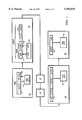
- FIG. 1 is a block diagram of part of a a digital data transmission network
- FIG. 2 is a more detailed block diagram of the CCF unit 23 in unit 20 of that network.
- a message transmission network is shown as including a source end unit 10 and three routing devices 20, 30, and 40. These illustrate part of the path of a particular data field through the network, which will of course include many such units.
- the source end unit 10 includes a register 11 in which the data field, which is to be sent to the destination unit 40, is generated.
- This unit 10 also includes a CRC circuit 13 which is fed with data field and calculates a CRC therefrom, and a CRC register 12 into which the CRC so calculated is fed.
- the CRC circuit 13 may be a look-up table unit or a feedback shift register unit.
- the CRC field is concatenated with the data field to form a packet PKT, which is transmitted by the unit 10.
- the packet is passed to a routing unit 20 which derives, from information provided by unit 10, the source and destination addresses (in the routing network) for transmitting the packet to a destination unit 30.
- these addresses are combined (possibly after conversion to other forms) to form a route information field RIF which is stored in a register 21.
- This unit 20 also includes a CCF circuit 23 which is fed with RIF field and calculates a CCF therefrom, and a CCF register 22 into which the CCF so calculated is fed.
- the RIF field may be generated in register 21 and passed to the CCF circuit 23 for the calculation of the CCF, or it may be generated in the CCF circuit 23 as described below and passed to the RIF register 21.
- the RIF field in register 21 is concatenated with the CCF field in register 22 to produce a header HDR.
- the packet itself from unit 10 is fed into a packet register 24, and this is concatenated with the header to produce a message MESS, which is transmitted by the unit 20.
- FIG. 2 shows the CCF circuit 23 in more detail.
- This circuit comprises a set of look-up tables 25-1 to 25-3, one for each subfield of the RIF, and an XOR accumulator 26.
- Each of the look-up tables contains a set of values for its subfield, together with the corresponding check subfield values. (It is convenient to store all three tables in a single memory, as shown, with all three subfields in each location, with each subfield value being accompanied by two unused and empty subfields, shown shaded.)
- a control unit 27 selects, from each look-up table in turn, the desired subfield value, which is passed to the RIF register 21. The selection of the subfield values may be determined, for example, in accordance with the desired final end unit to which the data is to be sent in combination with stored routing tables maintained by the unit 20 as part of the message network.
- the final contents of the accumulator 26 are passed to the CCF register 22.
- the CCF field generated by the CCF circuit 23 is thus concatenated with the CCF field to produce the header HDR as described above.
- the CCF circuit 23 also includes a check subfield calculation unit 28 for calculating the check subfields for newly generated RIF subfields. (Obviously the calculation of new check subfields may impose some delay on the operation of the unit 20.)
- the message is sent by routine unit 20 to a second routing unit 30, which checks the message.
- the message has its RIF, CCF, DATA, and CRC fields entered into a register 31.
- the routing unit also includes a CRC circuit 32 which is fed with contents of register 31 and calculates a CRC from the entire contents of the register 31. The fact that the CRC is included in the calculation means that the result should be a predetermined value.
- the CRC circuit 32 emits an error signal if some other value results.
- the CRC circuit 32 can be identical to the CRC circuit 13 of unit 10, apart from the fact that the CRC circuit 32 has to calculate its CRC from a longer quantity than the circuit 13.
- unit 30 is the final unit in the switching network.
- the header is stripped off the message by unit 30, which therefore passes only the packet part of the message on to the final destination unit, unit 40.
- This unit checks the packet, the whole of which (DATA and CRC fields) is entered into a register 41.
- the routing unit also includes a CRC circuit 42 which is fed with the contents of register 41 and calculates a CRC therefrom. This should yield a predetermined value; the CRC circuit 42 emits an error signal if some other value results.
- the message may be transmitted through any number of units similar to unit 30, as shown at 30' and 30".
- unit 30 may itself be the final unit.
- the unit 30 will be as shown, but will extract the DATA field directly from register 31, discarding the RIF and CCF fields.
- the single check performed by the CRC circuit 32 will in this case verify the integrity of both that the DATA field and the header.
- the header may need to be changed at some stage along the route of the message.
- a unit combining the features of units 20 and 30 would be required. More specifically, this would involve adding a CRC circuit (like unit 32) to unit 20. The incoming message would be entered into the complete message register, and its CRC checked by the CRC circuit. The incoming header would then be discarded, the new RIF field would then be determined, and finally the new CCF field would be determined by the unit 23.
- a CRC circuit like unit 32
- the CRC circuit 42 can be identical to the CRC circuits 13 and 32 of units 10 and 30, apart from the fact that the CRC circuit 42 has to calculate its CRC from a quantity of different length to the quantities dealt with by the circuit 32. Further, the CRC fields which are used to check the message in unit 30 and the packet in unit 40 are identical.
- the unit 40 may be the destination end unit for the data field; alternatively, the packet may be forwarded further through the network, eg with a new RIF being added by a unit corresponding to unit 20.
- a packet is originated in a unit 10 as a data field DATA 11 plus a CRC (cyclic redundancy check) check field CRC 12 by a CRC circuit 13.
- This packet has a header HDR (with a routing information field RIF) added to it in a unit 20, converting it into a message for transmission through a message network.
- a check correction field CCF is computed by unit 23 in unit 20, by looking up precomputed check subfields stored with the routing subfields (the routing information field being constructed by selecting from the stored subfields), such that the CRC field is a valid CRC check field for the complete message.
- unit 30 can be the final user unit, checking the entire message and extracting the data field DATA therefrom; the DATA field does not need to be checked, as the CRC field acts as a check both for the data field DATA alone and the entire message.
- the message can be checked by a final switching unit 30 using a standard CRC check circuit 32 (and similarly at intermediate units 30', 30") and the original packet can be checked by another standard CRC check circuit 42 in the final user unit 40.
Abstract
Description
x.sup.15 +x.sup.14 +. . . +x.sup.1 +1) (x.sup.k+16 +1),
Claims (6)
Priority Applications (2)
| Application Number | Priority Date | Filing Date | Title |
|---|---|---|---|
| US08/442,253 US5954835A (en) | 1992-06-23 | 1995-05-15 | Check sequence preservation |
| US09/398,488 US6425106B1 (en) | 1992-06-23 | 1999-09-17 | Extended ECC system |
Applications Claiming Priority (4)
| Application Number | Priority Date | Filing Date | Title |
|---|---|---|---|
| GB929213272A GB9213272D0 (en) | 1992-06-23 | 1992-06-23 | Check sequence preservation |
| GB9213272 | 1992-06-23 | ||
| US7228793A | 1993-06-04 | 1993-06-04 | |
| US08/442,253 US5954835A (en) | 1992-06-23 | 1995-05-15 | Check sequence preservation |
Related Parent Applications (1)
| Application Number | Title | Priority Date | Filing Date |
|---|---|---|---|
| US7228793A Continuation | 1992-06-23 | 1993-06-04 |
Related Child Applications (1)
| Application Number | Title | Priority Date | Filing Date |
|---|---|---|---|
| US09/398,488 Continuation US6425106B1 (en) | 1992-06-23 | 1999-09-17 | Extended ECC system |
Publications (1)
| Publication Number | Publication Date |
|---|---|
| US5954835A true US5954835A (en) | 1999-09-21 |
Family
ID=10717561
Family Applications (2)
| Application Number | Title | Priority Date | Filing Date |
|---|---|---|---|
| US08/442,253 Expired - Lifetime US5954835A (en) | 1992-06-23 | 1995-05-15 | Check sequence preservation |
| US09/398,488 Expired - Lifetime US6425106B1 (en) | 1992-06-23 | 1999-09-17 | Extended ECC system |
Family Applications After (1)
| Application Number | Title | Priority Date | Filing Date |
|---|---|---|---|
| US09/398,488 Expired - Lifetime US6425106B1 (en) | 1992-06-23 | 1999-09-17 | Extended ECC system |
Country Status (5)
| Country | Link |
|---|---|
| US (2) | US5954835A (en) |
| EP (1) | EP0600078B1 (en) |
| DE (1) | DE69329098T2 (en) |
| GB (1) | GB9213272D0 (en) |
| WO (1) | WO1994000937A1 (en) |
Cited By (12)
| Publication number | Priority date | Publication date | Assignee | Title |
|---|---|---|---|---|
| US6269464B1 (en) * | 1997-06-18 | 2001-07-31 | Sutmyn Storage Corporation | Error checking technique for use in mass storage systems |
| US6331978B1 (en) * | 1999-03-09 | 2001-12-18 | Nokia Telecommunications, Oy | Generic label encapsulation protocol for carrying label switched packets over serial links |
| US6601210B1 (en) * | 1999-09-08 | 2003-07-29 | Mellanox Technologies, Ltd | Data integrity verification in a switching network |
| US20040123221A1 (en) * | 2002-12-20 | 2004-06-24 | Huffman Amber D. | CRC calculation for data with dynamic header |
| US20040158794A1 (en) * | 2002-07-19 | 2004-08-12 | Niesen Joseph W. | Reduced overhead CRC functionality for packets and link layer superframes |
| US20040218623A1 (en) * | 2003-05-01 | 2004-11-04 | Dror Goldenberg | Hardware calculation of encapsulated IP, TCP and UDP checksums by a switch fabric channel adapter |
| US6826197B1 (en) * | 1999-04-01 | 2004-11-30 | Sedna Patent Services, Llc | Data packet structure for digital information distribution |
| US20050149823A1 (en) * | 2003-12-10 | 2005-07-07 | Samsung Electrionics Co., Ltd. | Apparatus and method for generating checksum |
| US20060168205A1 (en) * | 2005-01-24 | 2006-07-27 | Barron Gregory J | Network analysis system and method |
| US20060239287A1 (en) * | 2005-04-22 | 2006-10-26 | Johnsen Bjorn D | Adding packet routing information without ECRC recalculation |
| CN106708555A (en) * | 2016-06-29 | 2017-05-24 | 腾讯科技(深圳)有限公司 | Method and device for loading plug-ins |
| US10225046B2 (en) * | 2017-01-09 | 2019-03-05 | At&T Intellectual Property I, L.P. | Adaptive cyclic redundancy check for uplink control information encoding |
Families Citing this family (10)
| Publication number | Priority date | Publication date | Assignee | Title |
|---|---|---|---|---|
| GB2304006B (en) * | 1995-08-01 | 1999-08-25 | Plessey Semiconductors Ltd | Data transmission systems |
| GB9515741D0 (en) * | 1995-08-01 | 1995-10-04 | Plessey Semiconductors Ltd | Data transmission systems |
| KR100677070B1 (en) * | 1999-10-02 | 2007-02-01 | 삼성전자주식회사 | Error control method for video bitstream data in wireless multimedia communication and computer readable medium therefor |
| US6691273B2 (en) * | 2001-01-17 | 2004-02-10 | Telefonaktiebolaget Lm Ericsson (Publ) | Error correction using packet combining during soft handover |
| US6996658B2 (en) | 2001-10-17 | 2006-02-07 | Stargen Technologies, Inc. | Multi-port system and method for routing a data element within an interconnection fabric |
| US7899030B2 (en) * | 2002-09-11 | 2011-03-01 | Jinsalas Solutions, Llc | Advanced switching architecture |
| DE10361386B4 (en) * | 2003-12-29 | 2006-02-16 | Siemens Ag | Method for transmitting digital information packets in a data network |
| US7760700B2 (en) * | 2005-09-12 | 2010-07-20 | Qualcomm Incorporated | Fast control messaging mechanism for use in wireless network communications |
| WO2007034935A1 (en) * | 2005-09-21 | 2007-03-29 | Semiconductor Energy Laboratory Co., Ltd. | Cyclic redundancy check circuit and semiconductor device having the cyclic redundancy check circuit |
| DE102007029116A1 (en) * | 2007-06-25 | 2009-01-02 | Continental Automotive Gmbh | Method for operating a microcontroller and an execution unit and a microcontroller and an execution unit |
Citations (13)
| Publication number | Priority date | Publication date | Assignee | Title |
|---|---|---|---|---|
| US3872430A (en) * | 1973-11-23 | 1975-03-18 | Paul Emile Boudreau | Method and apparatus of error detection for variable length words using a polynomial code |
| US4151510A (en) * | 1978-04-27 | 1979-04-24 | Honeywell Information Systems | Method and apparatus for an efficient error detection and correction system |
| EP0003480A2 (en) * | 1977-12-30 | 1979-08-22 | Siemens Aktiengesellschaft | Circuit for converting binary information by means of check bits |
| US4541093A (en) * | 1982-04-28 | 1985-09-10 | Sony Corporation | Method and apparatus for error correction |
| US4577313A (en) * | 1984-06-04 | 1986-03-18 | Sy Kian Bon K | Routing mechanism with encapsulated FCS for a multi-ring local area network |
| US4937828A (en) * | 1988-11-04 | 1990-06-26 | Westinghouse Electric Corp. | High speed parallel CRC device for concatenated data frames |
| EP0441041A2 (en) * | 1990-02-06 | 1991-08-14 | Digital Equipment International Limited | Method and apparatus for generating a 48-bit frame check sequence |
| US5043989A (en) * | 1989-06-29 | 1991-08-27 | International Business Machines Corp. | Terminal adapter having a multiple HDLC communication channels receiver for processing control network management frames |
| EP0445730A2 (en) * | 1990-03-05 | 1991-09-11 | Nec Corporation | Error correction system capable of correcting an error in a packet header by the use of a Reed-Solomon code |
| US5062104A (en) * | 1988-09-26 | 1991-10-29 | Pacific Bell | Digital service unit for connecting data processing equipment to a telephone system based computer network |
| US5068854A (en) * | 1989-09-12 | 1991-11-26 | Cupertino, California U.S.A. | Error detection for fiber distributed interfaced optic link |
| US5121396A (en) * | 1988-10-27 | 1992-06-09 | International Business Machines Corp. | Preservation of crc integrity upon intentional data alteration during message transmission |
| US5251215A (en) * | 1992-01-13 | 1993-10-05 | At&T Bell Laboratories | Modifying check codes in data packet transmission |
Family Cites Families (1)
| Publication number | Priority date | Publication date | Assignee | Title |
|---|---|---|---|---|
| GB9213273D0 (en) * | 1992-06-23 | 1992-08-05 | Digital Equipment Int | Efficient atm cell synchronization |
-
1992
- 1992-06-23 GB GB929213272A patent/GB9213272D0/en active Pending
-
1993
- 1993-06-21 EP EP93916652A patent/EP0600078B1/en not_active Expired - Lifetime
- 1993-06-21 DE DE69329098T patent/DE69329098T2/en not_active Expired - Fee Related
- 1993-06-21 WO PCT/US1993/005918 patent/WO1994000937A1/en active IP Right Grant
-
1995
- 1995-05-15 US US08/442,253 patent/US5954835A/en not_active Expired - Lifetime
-
1999
- 1999-09-17 US US09/398,488 patent/US6425106B1/en not_active Expired - Lifetime
Patent Citations (13)
| Publication number | Priority date | Publication date | Assignee | Title |
|---|---|---|---|---|
| US3872430A (en) * | 1973-11-23 | 1975-03-18 | Paul Emile Boudreau | Method and apparatus of error detection for variable length words using a polynomial code |
| EP0003480A2 (en) * | 1977-12-30 | 1979-08-22 | Siemens Aktiengesellschaft | Circuit for converting binary information by means of check bits |
| US4151510A (en) * | 1978-04-27 | 1979-04-24 | Honeywell Information Systems | Method and apparatus for an efficient error detection and correction system |
| US4541093A (en) * | 1982-04-28 | 1985-09-10 | Sony Corporation | Method and apparatus for error correction |
| US4577313A (en) * | 1984-06-04 | 1986-03-18 | Sy Kian Bon K | Routing mechanism with encapsulated FCS for a multi-ring local area network |
| US5062104A (en) * | 1988-09-26 | 1991-10-29 | Pacific Bell | Digital service unit for connecting data processing equipment to a telephone system based computer network |
| US5121396A (en) * | 1988-10-27 | 1992-06-09 | International Business Machines Corp. | Preservation of crc integrity upon intentional data alteration during message transmission |
| US4937828A (en) * | 1988-11-04 | 1990-06-26 | Westinghouse Electric Corp. | High speed parallel CRC device for concatenated data frames |
| US5043989A (en) * | 1989-06-29 | 1991-08-27 | International Business Machines Corp. | Terminal adapter having a multiple HDLC communication channels receiver for processing control network management frames |
| US5068854A (en) * | 1989-09-12 | 1991-11-26 | Cupertino, California U.S.A. | Error detection for fiber distributed interfaced optic link |
| EP0441041A2 (en) * | 1990-02-06 | 1991-08-14 | Digital Equipment International Limited | Method and apparatus for generating a 48-bit frame check sequence |
| EP0445730A2 (en) * | 1990-03-05 | 1991-09-11 | Nec Corporation | Error correction system capable of correcting an error in a packet header by the use of a Reed-Solomon code |
| US5251215A (en) * | 1992-01-13 | 1993-10-05 | At&T Bell Laboratories | Modifying check codes in data packet transmission |
Cited By (20)
| Publication number | Priority date | Publication date | Assignee | Title |
|---|---|---|---|---|
| US6269464B1 (en) * | 1997-06-18 | 2001-07-31 | Sutmyn Storage Corporation | Error checking technique for use in mass storage systems |
| US6331978B1 (en) * | 1999-03-09 | 2001-12-18 | Nokia Telecommunications, Oy | Generic label encapsulation protocol for carrying label switched packets over serial links |
| US6826197B1 (en) * | 1999-04-01 | 2004-11-30 | Sedna Patent Services, Llc | Data packet structure for digital information distribution |
| US6601210B1 (en) * | 1999-09-08 | 2003-07-29 | Mellanox Technologies, Ltd | Data integrity verification in a switching network |
| US20040158794A1 (en) * | 2002-07-19 | 2004-08-12 | Niesen Joseph W. | Reduced overhead CRC functionality for packets and link layer superframes |
| US7155658B2 (en) * | 2002-12-20 | 2006-12-26 | Intel Corporation | CRC calculation for data with dynamic header |
| US20040123221A1 (en) * | 2002-12-20 | 2004-06-24 | Huffman Amber D. | CRC calculation for data with dynamic header |
| US20040218623A1 (en) * | 2003-05-01 | 2004-11-04 | Dror Goldenberg | Hardware calculation of encapsulated IP, TCP and UDP checksums by a switch fabric channel adapter |
| US20050149823A1 (en) * | 2003-12-10 | 2005-07-07 | Samsung Electrionics Co., Ltd. | Apparatus and method for generating checksum |
| US20060168205A1 (en) * | 2005-01-24 | 2006-07-27 | Barron Gregory J | Network analysis system and method |
| US20100135186A1 (en) * | 2005-01-24 | 2010-06-03 | Daintree Networks, Pty. Ltd. | Network Analysis System and Method |
| US7962606B2 (en) * | 2005-01-24 | 2011-06-14 | Daintree Networks, Pty. Ltd. | Network analysis system and method |
| US8370483B2 (en) | 2005-01-24 | 2013-02-05 | Daintree Networks, Pty. Ltd. | Network analysis system and method |
| US20060239287A1 (en) * | 2005-04-22 | 2006-10-26 | Johnsen Bjorn D | Adding packet routing information without ECRC recalculation |
| US8223745B2 (en) * | 2005-04-22 | 2012-07-17 | Oracle America, Inc. | Adding packet routing information without ECRC recalculation |
| CN106708555A (en) * | 2016-06-29 | 2017-05-24 | 腾讯科技(深圳)有限公司 | Method and device for loading plug-ins |
| CN106708555B (en) * | 2016-06-29 | 2019-01-22 | 腾讯科技(深圳)有限公司 | A kind of method and apparatus loading plug-in unit |
| US10225046B2 (en) * | 2017-01-09 | 2019-03-05 | At&T Intellectual Property I, L.P. | Adaptive cyclic redundancy check for uplink control information encoding |
| US10574394B2 (en) | 2017-01-09 | 2020-02-25 | At&T Intellectual Property I, L.P. | Adaptive cyclic redundancy check for uplink control information encoding |
| US11146357B2 (en) | 2017-01-09 | 2021-10-12 | At&T Intellectual Property I, L.P. | Adaptive cyclic redundancy check for uplink control information encoding |
Also Published As
| Publication number | Publication date |
|---|---|
| EP0600078B1 (en) | 2000-07-26 |
| DE69329098T2 (en) | 2001-03-22 |
| WO1994000937A1 (en) | 1994-01-06 |
| US6425106B1 (en) | 2002-07-23 |
| DE69329098D1 (en) | 2000-08-31 |
| GB9213272D0 (en) | 1992-08-05 |
| EP0600078A1 (en) | 1994-06-08 |
Similar Documents
| Publication | Publication Date | Title |
|---|---|---|
| US5954835A (en) | Check sequence preservation | |
| US4979174A (en) | Error correction and detection apparatus and method | |
| Castagnoli et al. | Optimization of cyclic redundancy-check codes with 24 and 32 parity bits | |
| EP0950300B1 (en) | Secondary channel using code violations | |
| US5935268A (en) | Method and apparatus for generating an error detection code for a modified data packet derived from an original data packet | |
| JP3549788B2 (en) | Multi-stage encoding method, multi-stage decoding method, multi-stage encoding device, multi-stage decoding device, and information transmission system using these | |
| US6014767A (en) | Method and apparatus for a simple calculation of CRC-10 | |
| US5931967A (en) | Method and apparatus for detection of errors in multiple-word communications | |
| EP0681381A1 (en) | Method and apparatus for modifying frame check sequences in intermediate high speed network nodes | |
| EP0233075B1 (en) | Method and apparatus for generating error detection check bytes for a data record | |
| WO1994015407A1 (en) | Efficient crc remainder coefficient generation and checking device and method | |
| JPH07177132A (en) | Check data generation system | |
| JP3404642B2 (en) | Method and apparatus for two-stage calculation of CRC-32 | |
| JP3283097B2 (en) | Communications system | |
| US20040098655A1 (en) | Rolling CRC scheme for improved error detection | |
| US7818650B2 (en) | Channel encoding apparatus and method | |
| US3961311A (en) | Circuit arrangement for correcting slip errors in receiver of cyclic binary codes | |
| US5694407A (en) | Method and an apparatus for modifying a FCS | |
| CA2364072C (en) | Interconnect system with error correction | |
| US4592054A (en) | Decoder with code error correcting function | |
| US6981195B2 (en) | Cyclic redundancy check with efficient re-computation of error detection code | |
| US6185715B1 (en) | Method of product code block encoding applicable to encoding an ATM cell | |
| KR20090017384A (en) | Method of dividing code block considering crc attachment | |
| US7516393B2 (en) | System and method of error detection for unordered data delivery | |
| Baicheva et al. | Some comments about CRC selection for the 5G nr specification |
Legal Events
| Date | Code | Title | Description |
|---|---|---|---|
| AS | Assignment |
Owner name: CABLETRON SYSTEMS, INC., NEW HAMPSHIRE Free format text: ASSIGNMENT OF ASSIGNORS INTEREST;ASSIGNOR:DIGITAL EQUIPMENT CORPORATION;REEL/FRAME:009050/0477 Effective date: 19980206 |
|
| STCF | Information on status: patent grant |
Free format text: PATENTED CASE |
|
| FEPP | Fee payment procedure |
Free format text: PAYOR NUMBER ASSIGNED (ORIGINAL EVENT CODE: ASPN); ENTITY STATUS OF PATENT OWNER: LARGE ENTITY |
|
| AS | Assignment |
Owner name: ENTERASYS NETWORKS, INC., NEW HAMPSHIRE Free format text: ASSIGNMENT OF ASSIGNORS INTEREST;ASSIGNOR:CABLETRON SYSTEMS, INC.;REEL/FRAME:011219/0376 Effective date: 20000929 |
|
| FPAY | Fee payment |
Year of fee payment: 4 |
|
| AS | Assignment |
Owner name: WELLS FARGO FOOTHILL, INC., CALIFORNIA Free format text: SECURITY AGREEMENT;ASSIGNOR:ENTERASYS NETWORKS, INC.;REEL/FRAME:017656/0552 Effective date: 20060516 Owner name: OBSIDIAN, LLC, CALIFORNIA Free format text: SECURITY AGREEMENT;ASSIGNOR:ENTERASYS NETWORKS, INC.;REEL/FRAME:017656/0552 Effective date: 20060516 |
|
| FPAY | Fee payment |
Year of fee payment: 8 |
|
| AS | Assignment |
Owner name: WELLS FARGO TRUST CORPORATION LIMITED, AS SECURITY Free format text: GRANT OF SECURITY INTEREST IN U.S. PATENTS;ASSIGNOR:ENTERASYS NETWORKS INC.;REEL/FRAME:025339/0875 Effective date: 20101109 |
|
| AS | Assignment |
Owner name: ENTERASYS NETWORKS, INC., MASSACHUSETTS Free format text: RELEASE AND REASSIGNMENT OF PATENTS AND PATENT APPLICATIONS AT REEL/FRAME NO. 17656/0552;ASSIGNORS:WELLS FARGO CAPITAL FINANCE, INC. (FORMERLY KNOWN AS WELLS FARGO FOOTHILL, INC.);ENTERPRISE COMMUNICATIONS FUNDING GMBH, AS SUCCESSOR IN INTEREST TO OBSIDIAN, LLC;REEL/FRAME:025406/0769 Effective date: 20101110 |
|
| FPAY | Fee payment |
Year of fee payment: 12 |
|
| AS | Assignment |
Owner name: ENTERASYS NETWORKS INC., MASSACHUSETTS Free format text: TERMINATION AND RELEASE OF SECURITY INTEREST IN PATENTS AT REEL/FRAME NO. 25339/0875;ASSIGNOR:WELLS FARGO TRUST CORPORATION LIMITED;REEL/FRAME:031558/0677 Effective date: 20131031 |
|
| AS | Assignment |
Owner name: SILICON VALLEY BANK, CALIFORNIA Free format text: SECURITY AGREEMENT;ASSIGNOR:ENTERASYS NETWORKS, INC.;REEL/FRAME:036189/0509 Effective date: 20150724 |
|
| AS | Assignment |
Owner name: EXTREME NETWORKS, INC., NEW HAMPSHIRE Free format text: ASSIGNMENT OF ASSIGNORS INTEREST;ASSIGNOR:ENTERASYS NETWORKS, INC.;REEL/FRAME:036467/0566 Effective date: 20150820 |
|
| AS | Assignment |
Owner name: EXTREME NETWORKS, INC., CALIFORNIA Free format text: ASSIGNMENT OF ASSIGNORS INTEREST;ASSIGNOR:ENTERASYS NETWORKS, INC.;REEL/FRAME:036538/0011 Effective date: 20150820 |
|
| AS | Assignment |
Owner name: SILICON VALLEY BANK, CALIFORNIA Free format text: AMENDED AND RESTATED PATENT AND TRADEMARK SECURITY AGREEMENT;ASSIGNOR:EXTREME NETWORKS, INC.;REEL/FRAME:040521/0762 Effective date: 20161028 |
|
| AS | Assignment |
Owner name: SILICON VALLEY BANK, CALIFORNIA Free format text: SECOND AMENDED AND RESTATED PATENT AND TRADEMARK SECURITY AGREEMENT;ASSIGNOR:EXTREME NETWORKS, INC.;REEL/FRAME:043200/0614 Effective date: 20170714 |
|
| AS | Assignment |
Owner name: ENTERASYS NETWORKS, INC., CALIFORNIA Free format text: RELEASE BY SECURED PARTY;ASSIGNOR:SILICON VALLEY BANK;REEL/FRAME:046047/0223 Effective date: 20180501 Owner name: BANK OF MONTREAL, NEW YORK Free format text: SECURITY INTEREST;ASSIGNOR:EXTREME NETWORKS, INC.;REEL/FRAME:046050/0546 Effective date: 20180501 Owner name: EXTREME NETWORKS, INC., CALIFORNIA Free format text: RELEASE BY SECURED PARTY;ASSIGNOR:SILICON VALLEY BANK;REEL/FRAME:046051/0775 Effective date: 20180501 |