US5914585A - Power sharing in computing systems with a plurality of electronic devices - Google Patents
Power sharing in computing systems with a plurality of electronic devices Download PDFInfo
- Publication number
- US5914585A US5914585A US08/802,508 US80250897A US5914585A US 5914585 A US5914585 A US 5914585A US 80250897 A US80250897 A US 80250897A US 5914585 A US5914585 A US 5914585A
- Authority
- US
- United States
- Prior art keywords
- power
- electronic devices
- battery
- bus
- power bus
- Prior art date
- Legal status (The legal status is an assumption and is not a legal conclusion. Google has not performed a legal analysis and makes no representation as to the accuracy of the status listed.)
- Expired - Fee Related
Links
Images


Classifications
-
- G—PHYSICS
- G06—COMPUTING; CALCULATING OR COUNTING
- G06F—ELECTRIC DIGITAL DATA PROCESSING
- G06F3/00—Input arrangements for transferring data to be processed into a form capable of being handled by the computer; Output arrangements for transferring data from processing unit to output unit, e.g. interface arrangements
- G06F3/01—Input arrangements or combined input and output arrangements for interaction between user and computer
- G06F3/03—Arrangements for converting the position or the displacement of a member into a coded form
- G06F3/033—Pointing devices displaced or positioned by the user, e.g. mice, trackballs, pens or joysticks; Accessories therefor
- G06F3/0354—Pointing devices displaced or positioned by the user, e.g. mice, trackballs, pens or joysticks; Accessories therefor with detection of 2D relative movements between the device, or an operating part thereof, and a plane or surface, e.g. 2D mice, trackballs, pens or pucks
- G06F3/03545—Pens or stylus
-
- G—PHYSICS
- G06—COMPUTING; CALCULATING OR COUNTING
- G06F—ELECTRIC DIGITAL DATA PROCESSING
- G06F1/00—Details not covered by groups G06F3/00 - G06F13/00 and G06F21/00
- G06F1/16—Constructional details or arrangements
- G06F1/1613—Constructional details or arrangements for portable computers
- G06F1/163—Wearable computers, e.g. on a belt
-
- G—PHYSICS
- G06—COMPUTING; CALCULATING OR COUNTING
- G06F—ELECTRIC DIGITAL DATA PROCESSING
- G06F1/00—Details not covered by groups G06F3/00 - G06F13/00 and G06F21/00
- G06F1/16—Constructional details or arrangements
- G06F1/1613—Constructional details or arrangements for portable computers
- G06F1/1632—External expansion units, e.g. docking stations
-
- G—PHYSICS
- G06—COMPUTING; CALCULATING OR COUNTING
- G06F—ELECTRIC DIGITAL DATA PROCESSING
- G06F1/00—Details not covered by groups G06F3/00 - G06F13/00 and G06F21/00
- G06F1/26—Power supply means, e.g. regulation thereof
-
- G—PHYSICS
- G06—COMPUTING; CALCULATING OR COUNTING
- G06F—ELECTRIC DIGITAL DATA PROCESSING
- G06F1/00—Details not covered by groups G06F3/00 - G06F13/00 and G06F21/00
- G06F1/26—Power supply means, e.g. regulation thereof
- G06F1/263—Arrangements for using multiple switchable power supplies, e.g. battery and AC
-
- G—PHYSICS
- G06—COMPUTING; CALCULATING OR COUNTING
- G06K—GRAPHICAL DATA READING; PRESENTATION OF DATA; RECORD CARRIERS; HANDLING RECORD CARRIERS
- G06K7/00—Methods or arrangements for sensing record carriers, e.g. for reading patterns
- G06K7/10—Methods or arrangements for sensing record carriers, e.g. for reading patterns by electromagnetic radiation, e.g. optical sensing; by corpuscular radiation
- G06K7/10544—Methods or arrangements for sensing record carriers, e.g. for reading patterns by electromagnetic radiation, e.g. optical sensing; by corpuscular radiation by scanning of the records by radiation in the optical part of the electromagnetic spectrum
- G06K7/10821—Methods or arrangements for sensing record carriers, e.g. for reading patterns by electromagnetic radiation, e.g. optical sensing; by corpuscular radiation by scanning of the records by radiation in the optical part of the electromagnetic spectrum further details of bar or optical code scanning devices
- G06K7/10881—Methods or arrangements for sensing record carriers, e.g. for reading patterns by electromagnetic radiation, e.g. optical sensing; by corpuscular radiation by scanning of the records by radiation in the optical part of the electromagnetic spectrum further details of bar or optical code scanning devices constructional details of hand-held scanners
-
- H—ELECTRICITY
- H02—GENERATION; CONVERSION OR DISTRIBUTION OF ELECTRIC POWER
- H02J—CIRCUIT ARRANGEMENTS OR SYSTEMS FOR SUPPLYING OR DISTRIBUTING ELECTRIC POWER; SYSTEMS FOR STORING ELECTRIC ENERGY
- H02J1/00—Circuit arrangements for dc mains or dc distribution networks
- H02J1/06—Two-wire systems
-
- H—ELECTRICITY
- H02—GENERATION; CONVERSION OR DISTRIBUTION OF ELECTRIC POWER
- H02J—CIRCUIT ARRANGEMENTS OR SYSTEMS FOR SUPPLYING OR DISTRIBUTING ELECTRIC POWER; SYSTEMS FOR STORING ELECTRIC ENERGY
- H02J7/00—Circuit arrangements for charging or depolarising batteries or for supplying loads from batteries
- H02J7/0063—Circuit arrangements for charging or depolarising batteries or for supplying loads from batteries with circuits adapted for supplying loads from the battery
-
- H—ELECTRICITY
- H02—GENERATION; CONVERSION OR DISTRIBUTION OF ELECTRIC POWER
- H02J—CIRCUIT ARRANGEMENTS OR SYSTEMS FOR SUPPLYING OR DISTRIBUTING ELECTRIC POWER; SYSTEMS FOR STORING ELECTRIC ENERGY
- H02J7/00—Circuit arrangements for charging or depolarising batteries or for supplying loads from batteries
- H02J7/0068—Battery or charger load switching, e.g. concurrent charging and load supply
-
- H—ELECTRICITY
- H02—GENERATION; CONVERSION OR DISTRIBUTION OF ELECTRIC POWER
- H02J—CIRCUIT ARRANGEMENTS OR SYSTEMS FOR SUPPLYING OR DISTRIBUTING ELECTRIC POWER; SYSTEMS FOR STORING ELECTRIC ENERGY
- H02J7/00—Circuit arrangements for charging or depolarising batteries or for supplying loads from batteries
- H02J7/007—Regulation of charging or discharging current or voltage
- H02J7/00712—Regulation of charging or discharging current or voltage the cycle being controlled or terminated in response to electric parameters
-
- H—ELECTRICITY
- H02—GENERATION; CONVERSION OR DISTRIBUTION OF ELECTRIC POWER
- H02J—CIRCUIT ARRANGEMENTS OR SYSTEMS FOR SUPPLYING OR DISTRIBUTING ELECTRIC POWER; SYSTEMS FOR STORING ELECTRIC ENERGY
- H02J7/00—Circuit arrangements for charging or depolarising batteries or for supplying loads from batteries
- H02J7/34—Parallel operation in networks using both storage and other dc sources, e.g. providing buffering
- H02J7/342—The other DC source being a battery actively interacting with the first one, i.e. battery to battery charging
Definitions
- the present invention relates generally to power sharing and power management in electronic systems, and, specifically, to a power management system in an environment in which multiple battery-powered electronic devices share their power resources to maximize operational life.
- the present invention also relates generally to a belt shaped personal docking apparatus that can be used to dock multiple battery operated electronic devices, each in its own holster shaped dock.
- Battery powered electronic devices are commonly utilized in business applications to support business operations. For example, in warehousing and route accounting environments, hand-held data terminals and code readers are commonly utilized. Other commonly utilized battery operated electronic devices for business operations include devices for data display, data collection and data transfer.
- the batteries of electronic devices As the batteries of electronic devices get exhausted after a few hours of operation, they must be recharged. Recharging involves transferring power from one source of power such as a battery charger to a rechargeable battery that is low on power.
- a battery charger In environments such as warehouses, docking stations are provided where batteries can be recharged.
- the docking station is usually placed in a single, fixed location which ties up the electronic device from use during docking.
- the docking station is usually kept at a distance away from the places of work and provides means to recharge the rechargeable batteries of the electronic devices when the batteries are exhausted.
- Some docking stations also provide means to transfer data. For example, in the case of batch-type data collection operations in a warehouse, data terminals that are typically employed for data collection may be placed into a docking station to transfer collected data to a remote computer for processing and to recharge the battery of the data terminal.
- Electronic devices that perform a lot of functions often tend to be useful. However, such multiple-function electronic devices are often heavy and bulky. Again, as more functionality is added to the electronic devices, they tend to consume more power and make it necessary for an operator to carry replacement batteries in order to keep them operational for extended periods of time. Although such electronic devices perform multiple functions, they become less portable as they get bulkier due to the addition of extra functions.
- a common approach to solving the problem of carrying electronic devices has been to provide a holster for the device that can be attached to a belt that is worn by an operator. With the help of the holster and the belt, the hands of an operator can be freed for other activities when the electronic device is not being used. If multiple electronic devices are employed by an operator in any work environment, the operator also typically carries multiple replacement batteries in order to keep all the devices operational for extended periods of time.
- the data terminal When an electronic device such as a data terminal is not docked in its docking station for recharging or data transfer, the data terminal is often carried by hand during operation and may be kept on the person of an operator in a holster for temporary storage. If the operator has to carry multiple electronic devices, the operator is likely to also carry one holster for each electronic device so that the electronic devices may be temporarily stored in the holster when it is not being used by the operator. Moreover, the operator is also likely to carry at least one replacement battery for each electronic device, especially for devices that are important for the business operations that also consume more power and are likely to need replacement batteries.
- the power consumption within each battery powered device is managed to prolong the power supply duration of the battery and keep the device operational.
- some devices are used more frequently than others, with the problem of having to replace the batteries or recharging the batteries more often in these devices than in others.
- the devices that need replacements for their batteries become inoperable and must be at least temporarily taken out of service. This problem occurs even when other devices, especially those that are seldom used and still have operational batteries, are available in the vicinity, often carried in holsters on the person of the operator.
- the battery management system comprises a plurality of electronic devices, a belt and a power bus.
- Each of the plurality of electronic devices contain a battery and independently operate when powered by the battery.
- the belt that supports the plurality of electronic devices, and has the power bus attached thereto.
- the power bus connectively engages ones of the plurality of electronic devices that are supported by the belt.
- at least one of the plurality of electronic devices being designated to provide power from its battery to the power bus when the at least one of the plurality of electronic devices is supported by the belt.
- the power bus supplies power from the at least one of the plurality of electronic devices to the others of the plurality of electronic devices that are supported by the belt and are connectively engaged to the power bus.
- the portable battery management system of claim 1 further comprises one or more independent batteries selectively supported by the belt. When the batteries are supported by the belt, they are coupled to the power bus. These one or more independent batteries are capable of replacing the batteries in one or more of the plurality of electronic devices. Further, the one or more independent batteries can be used as a power source to supply power on the power bus before the battery of one of the plurality of electronic devices is used to supply power to the power bus. In such and other embodiments, a hierarchy of power sources may be identified to supply such power on the power bus.
- the portable battery management system may also collect information from at least one of the plurality of electronic devices to identify at least one of the plurality of electronic devices to be used in supplying power to the power bus.
- FIG. 1 is a diagrammatic representation of an exemplary portable power management system built in accordance with the present invention wherein a belt not only supports a plurality of battery powered electronic devices but also couples holstered devices for communication and battery power management purposes;
- FIG. 2a depicts the operation of an exemplary power management system where the battery of one of the plurality of electronic devices depicted in FIG. 1 is used as a designated power source for the others of the plurality of electronic devices attached to the power bus;
- FIG. 2b is a flow diagram that describes the operation of an exemplary embodiment of the portable power management system where the individual electronic devices monitor the delivery of power on the power bus to determine if their batteries need to start delivering power on the power bus;
- FIG. 2c is a flow diagram that describes the operation of another exemplary portable power management functionality that is associated with electronic devices that participate as potential sources of power in the power management system of FIG. 1;
- FIG. 2d is a flow diagram that depicts the operation of a power management system that incorporates the specification of a hierarchy of batteries as power sources for the power bus and identifies a new power source using information collected on the status of the batteries and their current voltage level and current levels, when required;
- FIG. 3a depicts an exemplary power management system where the power management functionality is incorporated as part of one of the electronic devices docked on the power management system of FIG. 1;
- FIG. 3b depicts another exemplary portable power management circuitry for FIG. 1 where the management circuitry embodying the portable power management functionality is incorporated into multiple electronic devices, batteries, and some docks attached to the power bus, but not all electronic devices attached to the power bus need to have one;
- FIG. 4 depicts a power control circuitry with an external master controller that manages power for multiple electronic devices that can share power over a common power bus;
- FIG. 5 is a perspective view illustrating a portable power management system (such as that of FIG. 1) gaining access to external power resources of a vehicle;
- FIG. 6 is a diagram illustrating an alternate embodiment of FIG. 5 wherein the contacts located on the drivers seat are replaced with a buckling mechanism that couples the portable power management system with vehicle power resources;
- FIG. 7a is a perspective diagram illustrating the functionality of power management in portable power management systems not containing a belt
- FIG. 7b is a perspective diagram illustrating an embodiment of another exemplary portable power management system such as that of FIG. 7a which comprises matingly engaging sub-components;
- FIG. 8 is a schematic diagram that illustrates variations in location and operation of power management functionality (including hardware and associated software) within a portable power management system;
- FIG. 9 depicts another power management system where a power control circuitry 855 that manages power between two electronic battery operated devices (or sub-components) is included in one of the devices;
- FIG. 10 depicts an alternate embodiment of the power management system wherein power control functionality is distributed within a plurality of battery powered electronic devices
- FIG. 11 is another diagrammatic illustration of a user-supported information capture system in accordance with the present invention.
- FIGS. 12A and 12B are diagrammatic views showing an information capture system of the present invention wherein a belt is worn as a sling supported about the user's right or left shoulder and extending across the chest of a user;
- FIG. 13 is a diagrammatic view illustrating an exemplary arrangement of components on the belt shown in FIGS. 11, 12A and 12B;
- FIG. 14 is an elevation view of a typical hand-held data terminal to be utilized in conjunction with the present invention having a standard docking connector
- FIG. 15 is an illustration of a typical standard eight contact docking connector shown on the terminal of FIG. 14;
- FIG. 16 is a table showing a typical pin-out configuration of the standard contact docking connector of FIG. 15.
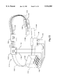
- FIGS. 17A, 17B, and 17C is a diagrammatic view of exemplary docking receptacles of the present invention for receiving hand-held data capture terminals.
- FIG. 1 is a diagrammatic representation of an exemplary portable power management system 9 built in accordance with the present invention wherein a belt not only supports a plurality of battery powered electronic devices but also couples holstered devices for communication and battery power management purposes.
- the exemplary portable power management system 9 might be a configuration used for warehousing or route accounting operations.
- a plurality of electronic devices i.e., a code reader 29, a printer 25, and a hand-held computing device 23, are used by an operator with support from a belt 11.
- the belt 11 may include a buckle 13 and a strap 31 for additional support.
- the operator uses the code reader 29 to collect information from coded images such as bar codes, and may wirelessly communicate via an antenna 7 with, for example, the computing device 23.
- the code reader 29 may communicate collected information to the computing device 23 via a communication bus 19 that is disposed on the belt 11 when inserted into a dock 27.
- the code reader 29 is carried in the dock 27 that is attached to the belt 11 when not in use.
- the computing device 23 may collect and communicate data to the code reader 29 wirelessly via an antenna 5 and/or via the wired communication bus 19.
- the printer 25 may also communicate with either the code reader 29 or with the computing device 23 via the communication bus 19. Although wireless capability is not shown in the printer 25, it may also be included therein. Although it may be removed, the printer 25 directly attaches to and hangs from the belt 11 during most operations.
- the docks may be shaped as holsters or as pouches, as illustrated.
- the electronic device engages the communication bus 19 and a power bus 17.
- the communication bus may be used to communicate data collection information among the electronic devices that are docked.
- the communication bus 19 is also used to communicate higher level power control information, when implemented.
- the power bus 17 supports power management functionality amongst the plurality of docked electronic devices.
- a major aspect of power management involves the sharing of battery power functionality amongst the plurality of docked electronic devices.
- Power sharing involves one or more of the docked devices providing all or some operational power to the others of the plurality of electronic devices when they are docked.
- power sharing may further involve one or more of the docked devices providing recharging power to the others of the plurality of electronic devices when they are docked, for operational power when they are not docked.
- a replacement rechargeable battery 33 may also be used in the portable power management system 9. Upon insertion of the battery 33 into a dock 15, the power from the battery 33 is made available to the plurality of docked electronic devices via the power bus. A plurality of replacement batteries can be used in the portable power management system 9.
- the code reader 29 may be designed as a small light weight unit with minimal battery capacity even if it to be used for extended periods of time if the device is able to recharge itself when it is docked.
- the code reader in an exemplary configuration would employ a much smaller and lighter battery that would last for half-an-hour of continuous operation. Such a smaller battery would then be charged using power from the power bus whenever the device was docked between operations and the code reader would be operational for extended periods of time.
- FIG. 2a depicts the operation of an exemplary power management system where the battery of one of the plurality of electronic devices depicted in FIG. 1 is used as a designated power source for the others of the plurality of electronic devices attached to the power bus.
- the electronic devices that are not designated as the power source may not be aware of the power management system, while they consume power available on the bus as they would from a charging unit. Therefore, standard off-the-shelf electronic devices can participate in this power management system.
- the power management system of FIG. 2a designates one of the replacement batteries, such as the replacement battery 33 of FIG. 1, as the power source and the designated replacement battery provides power on the power bus to the electronic devices and to other replacement batteries.
- the power bus is used to supply operational power to the devices and also power to recharge the batteries.
- the devices When the devices are docked in their docks, they consume power from the power bus 17 of FIG. 1 instead of their own batteries, as long as the power bus can supply power.
- This power on the power bus is delivered by the replacement battery 33 of FIG. 1 when it is docked in its battery dock 15, as long as the replacement battery can supply power.
- the power supplied by the replacement battery 33 can also be used to recharge the batteries currently plugged into the electronic devices while they are docked in their respective docks.
- the code reader 29 instead of drawing power from other devices, the code reader 29 might utilize power from the battery pack 33 if available.
- the battery pack may be used by other devices.
- the battery 33 may be used to replace a compatible exhausted battery in any one of the electronic devices if the devices can work on similar batteries.
- the replacement rechargeable battery 33 is typically usable only in some subset of the devices carried by an operator.
- the power management system starts its operation.
- the power management system determines if the power source (for example, the replacement battery 33 of FIG. 1) has power available so that power could be delivered to the power bus. If power is available, it is delivered to the power bus at a block 205. If power is not available or if the power in the power source if below a threshold value, delivery of power to the power bus 17 of FIG. 1 is halted.
- the power source for example, the replacement battery 33 of FIG. 1
- a replacement battery is considered as the primary source of power on the power bus and it supplies power on the power bus until its power is depleted or until its power falls below a threshold limit.
- the battery of some electronic device such as the printer 25 of FIG. 1 may be considered to be the source of power on the power bus 17.
- the batteries in any of the currently docked electronic devices with sufficiently high power level can be used as a source of power.
- the power on the power bus my be supplied by the battery of any of the currently docked electronic devices with sufficiently high power level.
- FIG. 2b is a flow diagram that describes the operation of an exemplary embodiment of the portable power management system where the individual electronic devices monitor the delivery of power on the power bus to determine if their batteries need to start delivering power on the power bus.
- each battery operated electronic device that is capable of delivering power may operate in cooperative mode and voluntarily deliver power to the power bus when they are able to access the power bus.
- each electronic device and replacement battery that participates as a potential power source may monitor the power bus in order to detect a disruption of power on the bus.
- a power disruption is detected by a potential power source, it pursues a random backoff strategy to determine if it should become the next power source.
- Such a strategy involves monitoring the power bus after a randomly generated backoff period and supplying power on to the power bus if power is not being delivered by any other electronic device or battery after the random backoff period.
- the power management system of FIG. 2b is a decentralized one, with the functionality described by FIG. 2b incorporated into each electronic device that actively participates in delivering power to the power bus as part of the power management system.
- the decentralized power management system of each electronic device starts at a block 211.
- an attempt is made to detect power on the power bus 17 of FIG. 1. If the power bus is found to be supplying power, then control is passed to the decision block 213 for further monitoring.
- the potential power source determines if it can be the next source of power at a block 215. If its power level is below a threshold, or if it has no power to supply, the potential power source returns control back to the block 213 for further monitoring. If, at the block 215, the potential power source determines that it can supply power on the power bus, it initiates a random backoff strategy at a block 217 before attempting to access the power bus at a block 219.
- the potential power source determines that power is already being supplied on the power bus by some other source of power, it returns control to the block 213 for further monitoring. If, at the block 219, the it is determined that there is no power supply on the power bus, the potential source of power starts delivering power to the power bus at a block 221. Power is delivered until the power is depleted or until the power level falls below a threshold level. The termination of power supply is detected at a block 223 and control is returned to the block 213 for further monitoring.
- the replacement battery 33 is used as the primary source of power to all the electronic devices that are currently docked in their docks.
- the battery of the printer 25 replaces the replacement battery 33 as the source of power, if its power level is high enough to permit its operation as a power source. In such a situation, the printer 25 monitors the power bus periodically to see if the power bus is able to provide consumable power to the electronic devices that are currently docked.
- the printer 25 determines that the replacement battery, or the device currently supplying power, has stopped supplying power, it connects its battery to the power bus and causes its battery to supply power on the power bus after waiting for a random backoff period and discovering no power on the power bus.
- a different electronic device may fill in for the replacement battery instead of the printer, as a source of power supplied over the power bus.
- the portable power management system of FIG. 2b provides a facility to share power. However, individual electronic devices may continue to use the power supplied by their own batteries when they are docked while also consuming power from the power bus. Again, when power supply on the power bus is disrupted, the electronic devices may choose to consume power from their own batteries.
- the printer 25 acts as the primary source of power for the power bus. It provides power to all the devices that are currently docked in their respective docks, even when a replacement battery is available. The printer continues to supply power until its power level falls below a threshold level, or until it exhausts its battery. When the printer stops supplying power on the power bus, the batteries in each electronic device starts delivering power to its associated device, as necessary.
- this approach may be generalized to include the batteries of other devices in addition to the battery of the printer. It is possible to arrange a hierarchy of batteries as the sources of power to be supplied over the power bus. Such a hierarchy could be static or dynamic in nature. The devices would be responsible to monitor the power bus to determine if their batteries should start supplying power on the power bus. Alternately, a portable power management system may be set up where one of the devices that is considered non-essential is targeted as a power source and drained of its power after the power in the replacement battery is exhausted. When this occurs, the device that becomes a power source is subsequently made inoperable until its battery is charged again.
- FIG. 2c describes another exemplary portable power management functionality that is associated with electronic devices that participate as potential sources of power in the power management system of FIG. 1.
- Such power management functionality can be located in electronic devices or there holsters that act as docks.
- the power management system of FIG. 2c makes it possible for devices that are replaced in their docks to volunteer to supply power on the power bus as soon as they are docked. If the power level of the battery of the electronic device (a potential power source) that is most recently docked is higher than that of the power source supplying power on the power bus, these two devices will negotiate to determine if there needs to be a change in power sources. Such negotiation would involve communication between the power source and the electronic device that is most recently docked. It is also possible to take into consideration the power levels of other potential power sources during such negotiations.
- the power management functionality of the device that participates as a potential power source starts at a block 241 and determines if the power bus is supplying power at a block 243. If the power bus is currently supplying power, a timer with a predetermined delay is set at a block 245 in order to participate in power negotiation later at a block 249, after the disruption of power on the power bus is discovered at a block 247.
- the elctronic devices or batteries that participate in power management as potential power sources negotiate on determining the next source of power for the power bus at a block 249. Such negotiations involve communications between the participating devices and replacement batteries over the power bus, or alternately, over the communication bus.
- the power management functionality of the electronic device identifies itself as a power source, power is delivered to the power bus at a block 253 until power depletion is discovered at a block 255 or until power supply handoff to another device or battery is discovered at a block 257 due to subsequent negotiations.
- FIG. 2d describes another approach to portable power management that involves the dynamic identification of the potential source of power among all the batteries, taking into consideration the status of all the batteries, the levels of voltage and current that can be supplied by each battery, and the priority of each electronic device.
- the portable power management functionality of FIG. 2d is a centralized approach where such could be located in one of the batteries or in one of the devices.
- Such a portable power management system would require communication between the power management system and the different batteries, with the ability to determine the status of all the batteries when required.
- the communication between the batteries could be carried out over the power bus. Alternately, such communication could be handled over a communication bus 19 of FIG. 1.
- FIG. 2d depicts the operation of a power control circuitry that incorporates the specification of a hierarchy of batteries as power sources for the power bus and identifies a new power source using information collected on the status of the batteries and their current voltage level and current levels, when required.
- the functionality provided by the power control circuitry is termed a power management system.
- the power management system is activated.
- the power management system access the status of all the batteries. It then determines the priority of each electronic device at a block 275. This information is important to determine the potential sources of power when the current source of power for the power bus is exhausted.
- the power management system arranges the batteries of all the electronic devices currently available in a hierarchy for the supply of power to the power bus. This hierarchy serves as a guide while determining subsequent sources of power as replacements to the current source of power.
- the power management system periodically determines the levels of voltage and current that can be supplied by the battery of each electronic device. It also periodically monitors the power bus at a block 281 to ensure power supply to all the devices. The power management system also determines the need to replace the current power source by a new power source at a block 279. If the current power source is determined to be a capable power source at the block 279, the power management system returns control to the block 283.
- the power management system identifies a new power source at a block 285.
- the power management system takes into consideration the priority of the potential sources of power, the current status of the batteries of these potential sources of power, and the levels of voltage and current that these potential power sources can provide. It also determines the duration for which the replacement source can be expected to be effective before the next replacement may have to be identified.
- the power management system After identifying the replacement for the current source of battery power at block 285, the power management system causes the old power source to switch off power supply to the power bus and the new power source to switch on. This switch in power source is accomplished with disrupting the operation of the electronic devices.
- One simple way of ensuring continuity of operation of each electronic device is to cause the individual batteries of each electronic device to provide power to the associated device for the short duration of the replacement of power sources for the power bus. Other similar mechanisms are also possible to accomplish this task.
- the power management system may be embodied in a power control circuitry.
- the power control functionality may be located in a device that acts as a power controller. Not all devices need to have such a functionality.
- the power control functionality may be located in at least one of the electronic devices while all devices need to support a power control protocol. Such a protocol would involve the ability to query the status of the different batteries over the power bus, the ability to designate one of a plurality of batteries as a source of power, and the ability to switch between different batteries for power.
- One advantage of being able to share batteries across devices in a power management system is that the operator can carry fewer replacement batteries for multiple devices. This also reduces the total weight that an operator wearing the belt of FIG. 1 has to carry.
- the power management system can cause another battery at an higher power level to recharge the one at a lower power level, especially if the device associated with the battery with lower power level is considered more important and critical than the device with a higher powered battery.
- the ability to share batteries across different types of batteries is another advantage of this invention. This is enabled by having the individual batteries supply a standard voltage to the power bus so that the different devices can access the power bus and consume power at the same standard voltage. To deliver power to the power bus at the same standard voltage or current level, the power from the individual batteries in each device is subjected to power regulation before being supplied to the power bus. This regulation operation can be performed by a regulator located within the battery, within the electronic device, or externally at the dock of the device.
- the electronic devices can communicate over a communication bus 19 of FIG. 1 when the devices are docked in their respective docks.
- the code reader 29 of FIG. 1 can send information to the printer 25 over the communication bus 19 when it is docked into its dock 27, in order to print information on collected data.
- the code reader 29 selectively communicates information to the printer over the RF link as long as the power level of the battery permits such communication. If the battery power level is low in the code reader 29, RF communication between the device 29 and the printer 25 can be discontinued. Subsequent communication between the code reader 29 and the printer 25 is resumed over the communication bus 19 when the code reader 29 is docked into its dock 27.
- the power management functionality can be located in a special backup replacement battery, such as the replacement battery 33 in FIG. 1. It is also possible to locate it in an electronic device such as a printer or a code reader.
- the main responsibility of the power management functionality would include collecting information on the status of the batteries in the different devices, collecting information on the power levels of the different devices, arranging for the supply of power on the power bus by the replacement battery or the battery of one of the electronic devices, monitoring the power bus, and switching the source of power from a battery of one device to a battery of another device as and when required.
- FIG. 3a depicts an exemplary power management system where the power management functionality is incorporated as part of one of the electronic devices docked on the power management system of FIG. 1.
- a management circuitry 319 incorporated within an electronic device 305 manages power for multiple electronic devices that can share power over a power bus 321.
- the electronic device 305 is a printer, although it could have been any other kind of electronic devices.
- a computing device 301, a code reader 303, and a printer 305 are connected to the power bus 321.
- the printer 305 includes the management circuitry 319 that embodies the power management functionality.
- the management circuitry 319 controls power bus 321 and facilitates the delivery of power on the power bus 321 to each electronic device capable of consuming the power from the power bus. It can cause the battery 317 of the printer 305 to provide power to other devices on the power bus. When the battery of the printer is no longer capable of supplying power to other devices, or when it its power is below a threshold level, the management circuitry 319 causes the power bus to stop supplying power. If another participating device on the power bus also has a management circuitry similar to the management circuitry 319, the management circuitry 319 may cause the battery of that electronic device to start supplying power on the power bus.
- the management circuitry 319 also facilitates the recharging of the battery of an electronic device using a battery of another device as a source of power.
- the management circuitry 319 in the printer 305 collects information on the status of the batteries (309 and 311) over the power bus 321 and determines the source and destination batteries for recharging other batteries. It also sends messages to the individual batteries to prepare them for recharging.
- the management circuitry of the batteries targeted for recharging are required to enable the recharging operation and connect the associated electronic device to the power bus 321.
- the battery that is determined to be the source of power is also sent a message to prepare it for the discharging of its power.
- the power bus 321 is connected to external recharging contacts 307.
- the external recharging contacts 307 may be connected to a vehicle power systems or an external power supply.
- the external power supply may also have a management circuitry.
- the management circuitry 319 identifies the availability of an external power source and causes the individual batteries in each electronic device to recharge from the external power source when one is available.
- the management circuitry 319 in FIG. 3 is located within the printer 305.
- the master controller may be located in one of the other electronic devices. Another option is to locate the master controller externally to all the devices.
- FIG. 3b depicts another exemplary portable power management circuitry for FIG. 1 where the management circuitry embodying the portable power management functionality is incorporated into multiple electronic devices, batteries, and some docks attached to the power bus, but not all electronic devices attached to the power bus need to have one.
- the printer 371 and the computing device 359 incorporate management circuitry 373, 357.
- the replacement batteries are controlled by a management circuitry 369, which may be part of the battery 365 or part of the holster shaped dock 367. Power management is implemented by the cooperation of the management circuitry in the various devices.
- FIG. 3b also indicates that not all electronic devices need to incorporate the power management circuitry.
- the code reader 361 does not have a management circuitry. It still consumes power supplied over the power bus when it is docked, and its battery 363 can be charged by the power supplied over the power bus.
- FIG. 4 depicts a power control circuitry with an external master controller that manages power for multiple electronic devices that can share power over a common power bus.
- Each device that needs to access power from a power bus 421 participates in a power management system that is embodied in one master controller 413 and a plurality of slave controllers.
- the master controller 413 interacts with the plurality of slave controllers to manage the delivery of power from the batteries of one or more devices to the others.
- a slave controller 417 facilitates the charging or discharging of a battery 411 of a code reader 403, as part of the power control functionality, under the control of the master controller 413.
- a slave controller 419 facilitates the charging or discharging of a battery associated with a printer 405, as part of the power control functionality, under the control of the master controller 413.
- the master controller 413 also manages the charging of the batteries of all the electronic devices from an external power source, made available via an external power contact 407, and over the power bus 421.
- the master controller can cause more than one battery to simultaneously provide power to the power bus. This would require the ability to connect the two batteries as the sources of power for the power bus.
- the master controller can cause two different batteries from two different electronic devices to alternately provide power to the power bus by periodically switching the connection of the two batteries to the power bus. This would require the ability to alternate the two batteries as the source of power.
- FIG. 5 is a perspective view illustrating a portable power management system (such as that of FIG. 1) gaining access to external power resources of a vehicle.
- vehicle power is utilized to provide operational and recharging power to the individual batteries of the multiple electronic devices that are docked in a belt 505.
- the vehicle power is made available at contacts 510 and 511 from a vehicle power source 515, typically the vehicle battery, via a control unit 513 and wires 508 and 509.
- the control unit 513 contains power management circuitry and functions as any replaceable battery might operate within the portable power management system, as previously described.
- the contacts 510 and 511 are glued to a seat 501 in the vehicle in an orientation that generally corresponds to the location of contacts 506 and 507 when the driver wearing the system 500 sits on the seat 501.
- the contacts 506 and 507 may be adjustably positioned on a strap 503 to correspondingly engage the contacts 510 and 511, respectively, accommodating drivers of differing height or sitting position.
- the contacts 510 and 511 contain magnetic portions built therein.
- the contacts 506 and 507 are iron based. Thus, when the driver is seated, the contacts 506 and 507 are magnetically drawn to the contacts 510 and 511. Other means for binding such as velcro may alternately be implemented.
- FIG. 6 is a diagram illustrating an alternate embodiment of FIG. 5 wherein the contacts located on the drivers seat are replaced with a buckling mechanism that couples the portable power management system with vehicle power resources.
- a power management system 550 is fitted with a buckle portion 557 having contacts connected to a battery bus 552.
- a control unit 563 is likewise attached to a buckle portion 561 which matingly engages the buckle portion 557 through manual interaction by the driver.
- the battery bus 552 is coupled to the control unit 563 which manages vehicle power delivery from a vehicle power source 565. Such power may then be used by the plurality of docked devices for recharging and operational power.
- FIG. 7a is a perspective diagram illustrating the functionality of power management in portable power management systems not containing a belt.
- the scheme discussed previously, along with the many possible variations, may also be implemented when two or more sub-components of a composite portable electronic system matingly engage.
- a portable battery management system 713 is made up of two sub-components: 1) a code reader 705 having a battery 707; and 2) a computing device 701 having a battery 703.
- the sub-components may operate in a synergistic manner or each sub-component may operate with functionality entirely independent of the other sub-component. Similar operation may also occur when the sub-components are separated.
- the battery 707 provides power to the code reader 705 so that capturing and decoding coded images may take place.
- the computing device 701 operates using the battery 703 when separated from the code reader 705.
- the two sub-components may communicate using a wireless link when separated in a manner similar to that when matingly coupled.
- the code reader 705 When separated, the sub-components utilize their own battery resources. However, when matingly engaged, power management functionality is implemented to extend the operating life of both devices as a pair, minimizing the need for stationary recharging.
- the code reader 705 may be designed with minimal battery power capacity to accommodate minimal size and weight constraints needed to perform optimal code reading functionality, while the computing device 701 may be designed to house excessive battery capacity for that needed merely for the computing device 701 because size and weight constraints may not be as critical.
- the code reader unit 705 can utilize battery power from the computing device 701.
- the sub-components can continue to operate far longer than otherwise would be possible, minimizing the frequency of needing stationary recharging.
- battery resource sharing when sub-components require mutual or synergistic operation, it does not matter if nearly every sub-component has working power resources. For if only one of the sub-components has depleted its battery resources, the system will not operate. Thus, with resource sharing, such a system can continue functioning much longer.
- the code reader 705 having a scanning window 711 and a trigger 715 may also operate in a detached state utilizing solely its battery 707 to perform data collection purposes. When the battery 707 is rung low, the operator may replace it with another recharged battery. Alternately, the code reader 705 can be plugged into computing device 701 having a screen 709 for continued operational and recharging power from the battery 703. After a period of time has passed during which data collection through the mated code reader 705 has taken place, the battery 707 may have reached a sufficient charging level to enable the operator to again remove the code reader 705 for independent operation.
- the power control functionality can be managed by any one or more or all sub-components. If the power control functionality is in both devices, one of them can take precedence over the other, they might negotiate their roles as master or slave, or they might operate as previously described with reference to FIG. 1.
- FIG. 7b is a perspective diagram illustrating an embodiment of another exemplary portable power management system such as that of FIG. 7a which comprises matingly engaging sub-components.
- the power management system illustrated includes a battery operated wand reader and pen 755 and a pen-based computing device 751, each of which can be operated individually, that can share power when the two are attached.
- the wand reader and pen 755 has a battery 757 that supplies power for code reading operations and for pen input functionality via a display 759 of the computing device 751.
- the wand reader and pen 755 enters a dormant state, delivering code information, if any, and accepting battery charging power from the battery 753 of the computing device 751.
- Contacts within the slot (not shown) link the two sub-components when docked.
- the electronic pen 755 when the battery 757 of the electronic pen 755 is running low on power, the electronic pen 755 beeps to indicate to the operator a need for docking.
- the battery 753 acts as the master while the battery 757 of the pen acts as the slave for power sharing and power control purposes.
- the battery 753 of the computing device 751 provides power to the battery 757 and to the reader/pen 755, but the batter 757 only powers itself. This is because of the great disparity in battery resources between the two batteries. Power management functionality may be located in the computing device 751, the reader/pen 755, or in both.
- FIG. 8 is a schematic diagram that illustrates variations in location and operation of power management functionality (including hardware and associated software) within a portable power management system.
- Power control circuitry that manages power between two electronic battery operated devices, e.g., a unit A 801 and a unit B 803, may exist as illustrated, independent from such devices.
- a power control circuitry 805 is located external to the unit A 801 and the unit B 803.
- the unit A 801 and unit B 803 operate when separate or when joined via the power control circuitry 805, and, in either case, they may operate with synergistic simultaneous functionality or independently of one another.
- the power levels of the batteries within the two devices are compared and power is supplied toward the unit that is determined to be in need battery power.
- Factors considered by the power control circuitry 805 include energy stored, anticipated energy needs, and unit type.
- the power control circuitry 805 may decide to transfer the power of the battery 811 of the unit B 803 to the battery 809 of the unit A 801. In this case, the device unit B is taken out of operation and its power is transferred to the other device. It can be appreciated that many other management schemes and variations may be implemented. For example, a simplistic scheme such as when the battery 807 always provides power toward the unit 803 may be implemented to accommodate embodiments such as that shown in FIG. 7b.
- FIG. 9 depicts another power management system where a power control circuitry 855 that manages power between two electronic battery operated devices (or sub-components) is included in one of the devices.
- a power control circuitry 855 that manages power between two electronic battery operated devices (or sub-components) is included in one of the devices.
- the power control circuitry 855 manages the power levels of the battery 859 of the unit A device 851 and the battery 861 of the unit B device 853.
- the unit B 853 may act as a master device for power control while the unit A 851 may act as a slave.
- Other functional interaction as discussed for example in relation to FIGS. 2a-c may alternately be implemented.
- FIG. 10 depicts an alternate embodiment of the power management system wherein power control functionality is distributed within a plurality of battery powered electronic devices.
- power supply circuitry 910 and 913 found in a unit A 901 and a unit B 903 cooperatively operate to carry out power management functionality via a power bus 909 (as described in the various embodiments mentioned previously).
- the power control circuitry in one of the units may be configured to dominate power management functionality, both may be configured to participate equally.
- a power supply circuit 913 in the unit B 903 provides both battery power and, when available, access to a larger energy source.
- that source is used as much as possible by both of the units A and B, 901 and 903.
- the power management functionality operates in a master/slave configuration when such larger energy source is available, and enters an alternate mode of power sharing when that source is not available.
- the unit B 903 may occasionally couple to AC power source.
- the unit A 901 which may not be able to directly couple to the AC power source, may do so indirectly via docking with the unit B 903.
- power supply circuitry needed to adapt the AC power source for use in powering the units A 901 and B 903 need not be located in both units. Only one, the unit B 903, needs to be so configured.
- FIGS. 8-11 illustrate pairs of sub-components, may additional sub-components may be added to each of such the portable power management systems.
- FIG. 11 is a diagrammatic illustration of a user-supported information capture system 1110 in accordance with the present invention, comprising a user-worn personal communication and docking system 1112 having a docking receptacle 1114 which removably receives a data capture system 1116.
- the docking receptacle 1114 is shown as removably secured to a belt 1118 which is to be fastened about the waist of a user, e.g., by means of cooperating end sections 1118A and 1118B of synthetic material which adhere where pressed together (such material being available commercially under the trademark VELCRO).
- FIGS. 12A and 12B are diagrammatic views showing an information capture system 1110 wherein the belt 1118 is to be worn as a sling supported about the user's right or left shoulder (e.g., the left shoulder in FIG. 12) and extending across the user's chest (and about the user's right side at about waist level for the disposition shown in FIG. 12).
- the belt 1118 is to be worn as a sling supported about the user's right or left shoulder (e.g., the left shoulder in FIG. 12) and extending across the user's chest (and about the user's right side at about waist level for the disposition shown in FIG. 12).
- an exemplary communications apparatus is indicated at 1140 which may be powered by a battery supply unit 1142.
- the communications means 1140 includes a radio-frequency transceiver, for example a PC card conforming to PCMCIA interface standards
- an appropriate antenna may be coupled at the RF input/output of the transceiver, and be protectively encased within the belt 18 as indicated at 44.
- Spare battery packs such as 1146, 1148 may be located at convenient points along the belt so that these battery packs are readily accessible should it be desired to replace the battery in the hand-held data capture terminal 1118 with one of these spare packs.
- FIG. 12B shows the apparatus slung about a first shoulder of the operator and slung under the armpit of the second shoulder to accommodate the load of the system 1110 and to minimize slippage.
- FIG. 13 is a diagrammatic view illustrating an exemplary arrangement of components on the belt 1118 of FIG. 11 or FIGS. 12A and 12B.
- the communications apparatus 1140 of FIGS. 11, 12A, and 12B is shown as comprised of microprocessor control module 1160 and a radio unit 1162.
- the interior portion 1126 of docking receptacle 1114 is designed to receive a portable data terminal (such as the terminal shown in FIGS. 14, 15, 17B and 17C) and may contain a plurality of electrical docking contacts 1150 which connect to mating contacts on a data terminal.
- the docking contacts 1150 preferably include power supply signals (VCC and GROUND) which are electrically connected to battery sources 1146 via connections 1152 and 1154 to charge the battery of the data terminal while docked in the docking receptacle 1114.
- the contacts 1150 also preferably include transmitter and receiver data lines (TX and RX respectively) which electrically connect to microprocessor unit 1160 via lines 1156 and 1158 to communicate with a radio transceiver (RADIO UNIT) 1162 for radio frequency communications and data transfer.
- the radio unit 1162 communicates with the microprocessor unit 1160 via data bus 1164.
- the antenna 1144 of the radio unit is preferably a flexible type antenna which is contained within or mounted upon the belt 1118 and is capable of flexing along with the flex of the belt 1118.
- An expansion unit (EXPANSION UNIT) 1166 is also provided which allows for additional processing features to be added to the belt (e.g., additional memory, transceiver modules, etc.).
- the expansion unit 1166 couples to the other components of the belt via communications line 1168.
- NORAND Corporation of Cedar Rapids, Iowa manufactures hand-held data capture terminals such as the module 6100 and 6400 which are provided with a standard eight contact docking connector as shown in FIGS. 14, 15, and 16.
- the data terminal 1116 preferably includes a standard eight pin female type recessed connector 1174 at the proximal end 1170 of the terminal 1116.
- the data terminal 1116 may also include other types of data transfer links such as an infrared data port 1172 for transferring data between the docking receptacle 1114 and the terminal 1116 via infrared transmissions.
- FIG. 15 illustrates the arrangement for the contacts of the standard connector 1174 of the data terminal 1116 shown in FIG. 14.
- An exemplary pin-out arrangement of connector pins 1-8 is given in FIG. 16 in a somewhat tabular format.
- FIGS. 17A, 17B, and 17C are a diagrammatic illustration of the insertion of a data terminal into a docking apparatus of the present invention wherein a preferred positioning of a docking receptacle is shown.
- the docking receptacle 1180 as shown in FIG. 14 is preferably disposed on the belt 1118 such that the force of gravity urges the terminal 1116 (such as shown in FIG. 17B) to remain in the docking receptacle 1180.
- the docking receptacle 1180 of FIG. 17A may include a latch type fastener 1182 which aids in securely retaining a data terminal therein.
- the docking receptacle preferably includes contacts 1176 which mate with contacts on the terminal to provide a communication link to expansion unit 1166 via communications link 1168 for data transfer therebetween.
- the expansion unit 1166 may be contained in an expansion unit housing 1200 accessible by a removable lid 1200A.
- the expansion unit may be the microprocessor unit 1160 of FIG. 13.
- FIG. 17B shows an alternate docking receptacle 1184 receiving a data terminal wherein a female connector unit 1174 (as shown in FIGS. 14 and 15) mates with a cooperating male connector 1186 in the docking receptacle.
- Male connector connects to communications link 1188 which provides connection to other components of the docking system 1112 (e.g. microprocessor unit 1160, battery unit 1146, etc.).
- FIG. 17 illustrates a preferred mounting angle of a docking receptacle 1184 on belt 1118.
- the docking receptacle is preferably rotated with respect to the line defined by belt 1118 such that the terminal 1116 points in a direction ergonomically accessible by an operator (i.e., the receptacle points towards the front of the user to easily accommodate insertion and removal of the terminal).
- the thus described embodiment maximizes both the retention of the terminal 1116 in the docking receptacle due to the force of gravity and the ease of insertion and removal of the terminal 1116 into and from the receptacle.
- the receptacle 1184 is rotated 30 degrees toward the user with respect to a line perpendicular to the line defined by belt 1118.
Abstract
Description
Claims (14)
Priority Applications (1)
| Application Number | Priority Date | Filing Date | Title |
|---|---|---|---|
| US08/802,508 US5914585A (en) | 1996-02-20 | 1997-02-20 | Power sharing in computing systems with a plurality of electronic devices |
Applications Claiming Priority (2)
| Application Number | Priority Date | Filing Date | Title |
|---|---|---|---|
| US1190296P | 1996-02-20 | 1996-02-20 | |
| US08/802,508 US5914585A (en) | 1996-02-20 | 1997-02-20 | Power sharing in computing systems with a plurality of electronic devices |
Publications (1)
| Publication Number | Publication Date |
|---|---|
| US5914585A true US5914585A (en) | 1999-06-22 |
Family
ID=26682923
Family Applications (1)
| Application Number | Title | Priority Date | Filing Date |
|---|---|---|---|
| US08/802,508 Expired - Fee Related US5914585A (en) | 1996-02-20 | 1997-02-20 | Power sharing in computing systems with a plurality of electronic devices |
Country Status (1)
| Country | Link |
|---|---|
| US (1) | US5914585A (en) |
Cited By (113)
| Publication number | Priority date | Publication date | Assignee | Title |
|---|---|---|---|---|
| WO2000007275A1 (en) * | 1998-07-28 | 2000-02-10 | Double-Time Battery Corporation | Wearable docking-holster system, with energy management, to support portable electronic devices |
| US6044280A (en) * | 1997-02-28 | 2000-03-28 | U.S. Philips Corporation | Arrangement in which a useful signal is transmitted between at least two device units |
| US6177778B1 (en) * | 1999-03-30 | 2001-01-23 | Alexander Manufacturing Corp. | Battery adapter capable of receiving power from at least two power sources and of being in a docking station, and a battery arrangement including a battery charger and a docking station |
| EP1113561A1 (en) * | 1999-12-27 | 2001-07-04 | Nec Corporation | Portable information terminal and power supply control method therefor |
| US20020076948A1 (en) * | 2000-10-16 | 2002-06-20 | Brian Farrell | Method of manufacturing a fabric article to include electronic circuitry and an electrically active textile article |
| EP1221752A1 (en) * | 2000-06-27 | 2002-07-10 | Fujitsu Ten Limited | Battery charging/discharging system |
| WO2002065379A1 (en) * | 2001-02-09 | 2002-08-22 | Industria De Diseño Textil S.A. (Inditex S.A.) | Portable device for reading barcodes and printing labels |
| US6483204B2 (en) * | 2000-06-30 | 2002-11-19 | Mitsubishi Denki Kabushiki Kaisha | Power supply system with information exchange between plural loads and plural power sources |
| US6561845B2 (en) * | 2000-12-27 | 2003-05-13 | International Business Machines Corporation | Distributed connector system for wearable computers |
| WO2003041206A1 (en) | 2001-10-11 | 2003-05-15 | Silverman Martin S | Digital battery |
| US20030129457A1 (en) * | 2002-01-10 | 2003-07-10 | Panasonic Ev Energy Co., Ltd. | Battery power source device, method for controlling the same, and method for providing address |
| WO2004004091A1 (en) * | 2002-07-01 | 2004-01-08 | France Telecom | Charger and recharge device |
| US6727197B1 (en) | 1999-11-18 | 2004-04-27 | Foster-Miller, Inc. | Wearable transmission device |
| US20040092186A1 (en) * | 2000-11-17 | 2004-05-13 | Patricia Wilson-Nguyen | Textile electronic connection system |
| US20040172527A1 (en) * | 1998-06-26 | 2004-09-02 | Canon Kabushiki Kaisha | System having devices connected via communication lines |
| US20040201931A1 (en) * | 2002-10-14 | 2004-10-14 | Dror Korcharz | Configurable multiple power source system |
| US20040214138A1 (en) * | 2003-04-25 | 2004-10-28 | Ivoclar Vivadent Ag | Light polymerization device |
| US20040263124A1 (en) * | 2003-06-30 | 2004-12-30 | Sony Electronics Inc. | System and method for reducing external battery capacity requirement for a wireless card |
| EP1505708A1 (en) * | 2002-05-13 | 2005-02-09 | Sun Bridge Corporation | Cordless device system |
| US20050052803A1 (en) * | 2003-09-10 | 2005-03-10 | Holger Richert | Configuration for N consumers of electric energy, of which M consumers are simultaneously supplied with energy |
| US20050080516A1 (en) * | 2002-10-15 | 2005-04-14 | David Pincu | Power over ethernet switch node for use in power pooling |
| US20050085212A1 (en) * | 2003-10-16 | 2005-04-21 | Arkadiy Peker | High power architecture for power over Ethernet |
| US6888338B1 (en) * | 2003-01-27 | 2005-05-03 | O2Micro International Limited | Portable computer and docking station having charging circuits with remote power sensing capabilities |
| US20050122140A1 (en) * | 2003-10-16 | 2005-06-09 | Arkadiy Peker | High power architecture for power over Ethernet |
| EP1542332A1 (en) * | 2003-12-11 | 2005-06-15 | Symbol Technologies, Inc. | Opportunistic power supply charge system for portable unit |
| US20050197094A1 (en) * | 2003-10-16 | 2005-09-08 | Yair Darshan | High power classification for power over Ethernet |
| US20050211187A1 (en) * | 2004-03-12 | 2005-09-29 | Harman Larry L | Control station with integrated collar recharging docking station for pet electronics products |
| US20060019629A1 (en) * | 2004-01-22 | 2006-01-26 | Yuval Berson | Redundant powered device circuit |
| US20060053324A1 (en) * | 2002-10-15 | 2006-03-09 | Yaniv Giat | Rack level power management for power over Ethernet |
| EP1752910A2 (en) * | 2000-02-11 | 2007-02-14 | Symbol Technologies, Inc. | Portable electronic terminal and data processing system |
| US20070236408A1 (en) * | 2006-03-30 | 2007-10-11 | Kabushiki Kaisha Toshiba | Computing device, computing device system and power control method |
| US20070266109A1 (en) * | 2006-05-11 | 2007-11-15 | Mark Mellott | Apparatus and method for sharing data among multiple terminal devices |
| US20070292749A1 (en) * | 2006-06-15 | 2007-12-20 | Richard Coombs | Battery assembly for vacuums |
| US20080054062A1 (en) * | 2006-09-04 | 2008-03-06 | Intermec Ip Corp. | Tool belt with smart cell technology |
| US20080098133A1 (en) * | 2005-01-06 | 2008-04-24 | Tamir Shaanan | Bi-Directional Wired Interface |
| US20080106232A1 (en) * | 2006-11-03 | 2008-05-08 | Research In Motion Limited | Electronic device, including handheld electronic device, with dual battery configuration and associated method |
| EP1921725A1 (en) * | 2006-11-09 | 2008-05-14 | Research In Motion Limited | Electronic device, including handheld electronic device, with dual battery configuration and associated method |
| US20080166968A1 (en) * | 2007-01-06 | 2008-07-10 | Apple Inc. | Apparatuses and methods that facilitate the transfer of power and information among electrical devices |
| US20080167088A1 (en) * | 2007-01-06 | 2008-07-10 | Apple Computer, Inc. | Apparatuses and methods that facilitate the transfer of power and information among electrical devices |
| US20080278113A1 (en) * | 2007-03-28 | 2008-11-13 | Eagle Fan | Structure for Linking Battery Charger And Storage Unit |
| US20090035609A1 (en) * | 2007-07-31 | 2009-02-05 | Apple Inc. | Intelligent universal rechargeable batteries for battery charging system for mobile and accessory devices |
| US20090033278A1 (en) * | 2007-07-31 | 2009-02-05 | Apple Inc. | Host machines for battery charging system |
| US20090033277A1 (en) * | 2007-07-31 | 2009-02-05 | Apple Inc. | Battery charging system and mobile and accessory devices |
| US20090096419A1 (en) * | 2007-10-15 | 2009-04-16 | Black & Decker Inc. | Bottom based balancing in lithium ion system |
| US20090096417A1 (en) * | 2007-10-12 | 2009-04-16 | Idzik Jacek S | Electronic device, including handheld electronic device with intelligent holster |
| US20090212744A1 (en) * | 2008-02-25 | 2009-08-27 | Werthman Dean A | System for use in gathering or processing data in a healthcare facility having fleet of mobile workstations |
| US20090212848A1 (en) * | 2008-02-25 | 2009-08-27 | Gary Coonan | Power supply unit for mobile workstation and method |
| US20090212738A1 (en) * | 2008-02-25 | 2009-08-27 | Gary Coonan | Battery charging system and method of reducing variation in battery charging cycle count |
| US20090262266A1 (en) * | 2008-02-25 | 2009-10-22 | Lee Melvin Harbin | Power system petrofit kit for mobile workstation and retrofit method |
| US20090261656A1 (en) * | 2008-02-25 | 2009-10-22 | Gary Coonan | Power system for mobile workstation and method |
| US20090268385A1 (en) * | 2008-02-25 | 2009-10-29 | Lee Melvin Harbin | Mobile workstation having power system with removable battery configured for drop-in engagement therewith |
| US20090276104A1 (en) * | 2008-02-25 | 2009-11-05 | Gary Coonan | Mobile workstation control system configured for power system and peripheral device control |
| US20090276637A1 (en) * | 2008-02-25 | 2009-11-05 | Gary Coonan | Power control system for mobile workstation and method |
| US20110016333A1 (en) * | 2009-07-15 | 2011-01-20 | Microsoft Corporation | Power Transfer Between Devices |
| US20110016332A1 (en) * | 2009-07-15 | 2011-01-20 | Shuguang Wu | System and Method for Powering an Information Handling System Through a Display Cable |
| US20110133695A1 (en) * | 2009-12-09 | 2011-06-09 | Richard Cadway | Power Tool Battery Cell Replacement Kit and Methods Thereof |
| US20110260556A1 (en) * | 2008-09-30 | 2011-10-27 | Tectonica Australia Pty Ltd. | Personal portable power distribution apparatus |
| DE102010048469A1 (en) * | 2010-10-14 | 2012-04-19 | Rockwell Collins Deutschland Gmbh | Energy management system, method for distributing energy in an energy management system, terminal for an energy management system and central device for an energy management system |
| US8271806B1 (en) | 2007-03-20 | 2012-09-18 | Cypress Semiconductor Corporation | Method, system and device for communication based power sharing |
| US20120306434A1 (en) * | 2011-06-02 | 2012-12-06 | Jonathan Mark Sassen | Lightweight power system for continuously charging multiple battery powered devices carried by a dismounted soldier |
| US20130076302A1 (en) * | 2011-03-30 | 2013-03-28 | Quipos Solutions Gmbh | System for Charging Portable Electronic Devices |
| EP2582005A1 (en) * | 2011-10-14 | 2013-04-17 | Research In Motion Limited | Clip-on charging system with variable charging rates |
| US20130227309A1 (en) * | 2012-02-29 | 2013-08-29 | Quanta Computer Inc. | Server system |
| US8585606B2 (en) | 2010-09-23 | 2013-11-19 | QinetiQ North America, Inc. | Physiological status monitoring system |
| WO2014105230A1 (en) | 2012-12-27 | 2014-07-03 | Intel Corporation | Power management system and method |
| US8786251B2 (en) | 2011-10-14 | 2014-07-22 | Blackberry Limited | Clip-on charging system with variable charging rates |
| US8812881B1 (en) * | 2011-06-21 | 2014-08-19 | Google Inc. | Distributed uninterruptible power supply |
| JP2014525218A (en) * | 2011-07-24 | 2014-09-25 | 株式会社マキタ | Charger for handheld power tool, power tool system, and method of charging power tool battery |
| US20140303507A1 (en) * | 2003-12-17 | 2014-10-09 | Physio-Control, Inc. | External defibrillator with power and battery sharing capabilities with a pod |
| US9028404B2 (en) | 2010-07-28 | 2015-05-12 | Foster-Miller, Inc. | Physiological status monitoring system |
| US20150194829A1 (en) * | 2014-01-07 | 2015-07-09 | Limitless Innovations, Inc. | System for charging multiple devices |
| US9211085B2 (en) | 2010-05-03 | 2015-12-15 | Foster-Miller, Inc. | Respiration sensing system |
| GB2530064A (en) * | 2014-09-11 | 2016-03-16 | Thales Holdings Uk Plc | A harness |
| US9343924B2 (en) | 2013-03-25 | 2016-05-17 | Samsung Electronics Co., Ltd. | Method and wearable device for energy sharing network |
| US9483891B1 (en) | 2015-11-20 | 2016-11-01 | International Business Machines Corporation | Wireless lock |
| US9537335B2 (en) | 2011-07-24 | 2017-01-03 | Makita Corporation | Adapter for power tools, power tool system and method for wirelessly communicating maintenance information therefor |
| US9553466B2 (en) | 2010-10-27 | 2017-01-24 | Makita Corporation | Electric power tool system |
| US9563235B2 (en) * | 2015-02-27 | 2017-02-07 | Boe Technology Group Co., Ltd. | Wearable device |
| US20170083073A1 (en) * | 2015-09-23 | 2017-03-23 | International Business Machines Corporation | Managed collaborative charging |
| US9634491B2 (en) | 2009-07-10 | 2017-04-25 | Protonex Technology Corporation | Power managers and methods for operating power managers |
| US9634485B2 (en) | 2013-04-01 | 2017-04-25 | Protonex Technology Corporation | Power manager |
| US9696782B2 (en) | 2015-02-09 | 2017-07-04 | Microsoft Technology Licensing, Llc | Battery parameter-based power management for suppressing power spikes |
| US9729145B2 (en) | 2012-06-12 | 2017-08-08 | Infineon Technologies Ag | Circuit and a method for selecting a power supply |
| US9748780B2 (en) | 2010-10-27 | 2017-08-29 | Makita Corporation | Electric power tool system |
| US9748765B2 (en) | 2015-02-26 | 2017-08-29 | Microsoft Technology Licensing, Llc | Load allocation for multi-battery devices |
| US9793570B2 (en) | 2015-12-04 | 2017-10-17 | Microsoft Technology Licensing, Llc | Shared electrode battery |
| US9806772B2 (en) | 2007-01-06 | 2017-10-31 | Apple Inc. | Apparatuses and methods that facilitate the transfer of power and information among radio frequency-based devices |
| USD802533S1 (en) | 2016-03-23 | 2017-11-14 | Protonex Technology Corporation | Portable power manager enclosure |
| US20170337025A1 (en) * | 2016-05-17 | 2017-11-23 | Google Inc. | Dual screen haptic enabled convertible laptop |
| US20170363934A1 (en) * | 2016-06-16 | 2017-12-21 | Debra Stack | Instant photo system |
| US9933454B2 (en) | 2014-06-06 | 2018-04-03 | Advantest Corporation | Universal test floor system |
| US9939862B2 (en) | 2015-11-13 | 2018-04-10 | Microsoft Technology Licensing, Llc | Latency-based energy storage device selection |
| US10061366B2 (en) | 2015-11-17 | 2018-08-28 | Microsoft Technology Licensing, Llc | Schedule-based energy storage device selection |
| US10158148B2 (en) | 2015-02-18 | 2018-12-18 | Microsoft Technology Licensing, Llc | Dynamically changing internal state of a battery |
| US10274984B2 (en) * | 2016-11-15 | 2019-04-30 | Cisco Technology, Inc. | Network energy distribution |
| US10283975B1 (en) * | 2016-03-28 | 2019-05-07 | Amazon Technologies, Inc. | Smart diagnostics for hot-pluggable battery systems |
| US10326284B2 (en) | 2014-11-11 | 2019-06-18 | Revision Military Ltd. | Control module for DC power network |
| US20190229559A1 (en) * | 2018-01-23 | 2019-07-25 | Stryker Corporation | Operating room wireless power transfer |
| US20190341789A1 (en) * | 2018-05-07 | 2019-11-07 | David R. Hall | Power Sharing System |
| US10587116B2 (en) | 2015-11-20 | 2020-03-10 | Galvion Soldier Power, Llc | Distributed power manager |
| US10848067B2 (en) | 2015-11-20 | 2020-11-24 | Galvion Soldier Power, Llc | Power manager with reconfigurable power converting circuits |
| DE102019208367A1 (en) * | 2019-06-07 | 2020-12-10 | Comlogo GmbH | System for the electrical contacting of hanging loops and hooks |
| US10910855B2 (en) * | 2017-07-31 | 2021-02-02 | Seyed Mehdi Doorandish | Wearable multifunction power bank |
| US10926099B2 (en) | 2012-05-08 | 2021-02-23 | Physio-Control, Inc. | Utility module interface |
| EP3838055A1 (en) * | 2015-06-11 | 2021-06-23 | Positec Power Tools (Suzhou) Co., Ltd | Power transmission apparatus and control method therefor, and power supply system |
| US11166628B2 (en) | 2016-02-02 | 2021-11-09 | Physio-Control, Inc. | Laryngoscope with handle-grip activated recording |
| US11258366B2 (en) | 2015-11-20 | 2022-02-22 | Galvion Soldier Power, Llc | Power manager with reconfigurable power converting circuits |
| EP3975364A1 (en) * | 2020-09-29 | 2022-03-30 | Thales | Device for managing power supply, associated system, method and computer program |
| DE102021103978A1 (en) | 2021-02-19 | 2022-08-25 | Hochschule Hamm-Lippstadt, Körperschaft des öffentlichen Rechts | Modular charging system and module for small electrical devices |
| US20220385325A1 (en) * | 2021-05-26 | 2022-12-01 | Getac Technology Corporation | Adaptive power and communication routing for body-worn devices |
| US11601002B2 (en) | 2015-03-13 | 2023-03-07 | Positec Power Tools (Suzhou) Co., Ltd. | Electrical energy transmission apparatus, method for controlling same, and power supply system |
| US11808823B2 (en) | 2021-06-02 | 2023-11-07 | Getac Technology Corporation | Detection of device dislocation using power and non-powered dislocation sensors |
| US11864271B2 (en) | 2021-09-21 | 2024-01-02 | Getac Technology Corporation | Mobile device ID tracking for automatic incident data association and correlation |
Citations (30)
| Publication number | Priority date | Publication date | Assignee | Title |
|---|---|---|---|---|
| US2372971A (en) * | 1943-08-28 | 1945-04-03 | Harry W Moore | Halfvest carrier for hearing aids and batteries |
| US3274476A (en) * | 1963-10-30 | 1966-09-20 | Wildum Paul | Article carrying belt |
| US3811050A (en) * | 1973-07-13 | 1974-05-14 | Bell Telephone Labor Inc | Interlocked power supply transfer circuit to inhibit secondary transfer after a primary transfer |
| US3919615A (en) * | 1974-03-18 | 1975-11-11 | Ronald Niecke | Power belt |
| US4108341A (en) * | 1976-01-28 | 1978-08-22 | Siegfried Pettinger | Carrying belt for batteries |
| US4345286A (en) * | 1979-04-10 | 1982-08-17 | Olympus Optical Co., Ltd. | Power supply device for a multifunction apparatus having a plurality of power sources |
| US4419616A (en) * | 1980-12-29 | 1983-12-06 | Chevron Research Company | Power-up rack and method of use in association with portable microcomputers within a refinery and the like |
| US4481458A (en) * | 1983-04-11 | 1984-11-06 | Levitt-Safety Limited | Miners lamp power pack |
| US4531240A (en) * | 1982-09-29 | 1985-07-23 | Canon Kabushiki Kaisha | Data communication system |
| US4539487A (en) * | 1982-11-26 | 1985-09-03 | Mitsubishi Denki Kabushiki Kaisha | Power supply system |
| US4647831A (en) * | 1986-04-04 | 1987-03-03 | John Zink Company | Rechargeable battery operated appliance system |
| US4659942A (en) * | 1985-06-03 | 1987-04-21 | The Charles Stark Draper Laboratory, Inc. | Fault-tolerant power distribution system |
| US4672292A (en) * | 1985-05-14 | 1987-06-09 | Black & Decker Inc. | System for charging sets of rechargeable batteries |
| US4698517A (en) * | 1983-09-13 | 1987-10-06 | Nec Corporation | Power supply source control system |
| US4716352A (en) * | 1984-12-26 | 1987-12-29 | Black & Decker, Inc. | Charging base for a battery-powered appliance |
| US4739242A (en) * | 1984-12-17 | 1988-04-19 | Solid State Chargers Research And Development Limited Partnership | Multistation modular charging system for cordless units |
| US4748344A (en) * | 1987-03-23 | 1988-05-31 | Peter Sing | Portable power supply carrier |
| US5052943A (en) * | 1989-03-23 | 1991-10-01 | Norand Corporation | Recharging and data retrieval apparatus |
| US5055763A (en) * | 1988-09-26 | 1991-10-08 | Eveready Battery Company, Inc. | Electronic battery charger device and method |
| US5124532A (en) * | 1990-07-09 | 1992-06-23 | Hafey Marilyn J | Organizer for cordless electrically energized hair salon utensils |
| US5266838A (en) * | 1991-12-05 | 1993-11-30 | Thinking Machines Corporation | Power supply system including power sharing control arrangement |
| US5369565A (en) * | 1991-10-04 | 1994-11-29 | Innova Electronics Corp. | Modular power supply system |
| US5381554A (en) * | 1992-11-24 | 1995-01-10 | Exide Electronics | Uninterrupted power supply (UPS) system interfacing with communications network |
| US5422558A (en) * | 1993-05-05 | 1995-06-06 | Astec International Ltd. | Multicell battery power system |
| US5635813A (en) * | 1993-12-21 | 1997-06-03 | Mitsubishi Denki Kabushiki Kaisha | Electronic apparatus, battery management system, and battery management method |
| US5642517A (en) * | 1990-11-19 | 1997-06-24 | Seiko Epson Corporation | Docking system |
| US5680026A (en) * | 1994-03-21 | 1997-10-21 | Tyton Corporation | Tool belt with battery assembly |
| US5726506A (en) * | 1995-06-05 | 1998-03-10 | Alantec Corporation | Hot insertion power arrangement |
| US5745670A (en) * | 1996-06-11 | 1998-04-28 | Lanart Corporation | Fault tolerant power supply system |
| US5747889A (en) * | 1996-07-31 | 1998-05-05 | Hewlett-Packard Company | Redundant power supply and storage system |
-
1997
- 1997-02-20 US US08/802,508 patent/US5914585A/en not_active Expired - Fee Related
Patent Citations (30)
| Publication number | Priority date | Publication date | Assignee | Title |
|---|---|---|---|---|
| US2372971A (en) * | 1943-08-28 | 1945-04-03 | Harry W Moore | Halfvest carrier for hearing aids and batteries |
| US3274476A (en) * | 1963-10-30 | 1966-09-20 | Wildum Paul | Article carrying belt |
| US3811050A (en) * | 1973-07-13 | 1974-05-14 | Bell Telephone Labor Inc | Interlocked power supply transfer circuit to inhibit secondary transfer after a primary transfer |
| US3919615A (en) * | 1974-03-18 | 1975-11-11 | Ronald Niecke | Power belt |
| US4108341A (en) * | 1976-01-28 | 1978-08-22 | Siegfried Pettinger | Carrying belt for batteries |
| US4345286A (en) * | 1979-04-10 | 1982-08-17 | Olympus Optical Co., Ltd. | Power supply device for a multifunction apparatus having a plurality of power sources |
| US4419616A (en) * | 1980-12-29 | 1983-12-06 | Chevron Research Company | Power-up rack and method of use in association with portable microcomputers within a refinery and the like |
| US4531240A (en) * | 1982-09-29 | 1985-07-23 | Canon Kabushiki Kaisha | Data communication system |
| US4539487A (en) * | 1982-11-26 | 1985-09-03 | Mitsubishi Denki Kabushiki Kaisha | Power supply system |
| US4481458A (en) * | 1983-04-11 | 1984-11-06 | Levitt-Safety Limited | Miners lamp power pack |
| US4698517A (en) * | 1983-09-13 | 1987-10-06 | Nec Corporation | Power supply source control system |
| US4739242A (en) * | 1984-12-17 | 1988-04-19 | Solid State Chargers Research And Development Limited Partnership | Multistation modular charging system for cordless units |
| US4716352A (en) * | 1984-12-26 | 1987-12-29 | Black & Decker, Inc. | Charging base for a battery-powered appliance |
| US4672292A (en) * | 1985-05-14 | 1987-06-09 | Black & Decker Inc. | System for charging sets of rechargeable batteries |
| US4659942A (en) * | 1985-06-03 | 1987-04-21 | The Charles Stark Draper Laboratory, Inc. | Fault-tolerant power distribution system |
| US4647831A (en) * | 1986-04-04 | 1987-03-03 | John Zink Company | Rechargeable battery operated appliance system |
| US4748344A (en) * | 1987-03-23 | 1988-05-31 | Peter Sing | Portable power supply carrier |
| US5055763A (en) * | 1988-09-26 | 1991-10-08 | Eveready Battery Company, Inc. | Electronic battery charger device and method |
| US5052943A (en) * | 1989-03-23 | 1991-10-01 | Norand Corporation | Recharging and data retrieval apparatus |
| US5124532A (en) * | 1990-07-09 | 1992-06-23 | Hafey Marilyn J | Organizer for cordless electrically energized hair salon utensils |
| US5642517A (en) * | 1990-11-19 | 1997-06-24 | Seiko Epson Corporation | Docking system |
| US5369565A (en) * | 1991-10-04 | 1994-11-29 | Innova Electronics Corp. | Modular power supply system |
| US5266838A (en) * | 1991-12-05 | 1993-11-30 | Thinking Machines Corporation | Power supply system including power sharing control arrangement |
| US5381554A (en) * | 1992-11-24 | 1995-01-10 | Exide Electronics | Uninterrupted power supply (UPS) system interfacing with communications network |
| US5422558A (en) * | 1993-05-05 | 1995-06-06 | Astec International Ltd. | Multicell battery power system |
| US5635813A (en) * | 1993-12-21 | 1997-06-03 | Mitsubishi Denki Kabushiki Kaisha | Electronic apparatus, battery management system, and battery management method |
| US5680026A (en) * | 1994-03-21 | 1997-10-21 | Tyton Corporation | Tool belt with battery assembly |
| US5726506A (en) * | 1995-06-05 | 1998-03-10 | Alantec Corporation | Hot insertion power arrangement |
| US5745670A (en) * | 1996-06-11 | 1998-04-28 | Lanart Corporation | Fault tolerant power supply system |
| US5747889A (en) * | 1996-07-31 | 1998-05-05 | Hewlett-Packard Company | Redundant power supply and storage system |
Cited By (224)
| Publication number | Priority date | Publication date | Assignee | Title |
|---|---|---|---|---|
| US6044280A (en) * | 1997-02-28 | 2000-03-28 | U.S. Philips Corporation | Arrangement in which a useful signal is transmitted between at least two device units |
| US20040172527A1 (en) * | 1998-06-26 | 2004-09-02 | Canon Kabushiki Kaisha | System having devices connected via communication lines |
| WO2000007275A1 (en) * | 1998-07-28 | 2000-02-10 | Double-Time Battery Corporation | Wearable docking-holster system, with energy management, to support portable electronic devices |
| US6184654B1 (en) * | 1998-07-28 | 2001-02-06 | Double-Time Battery Corporation | Wearable docking-holster system, with energy management, to support portable electronic devices |
| US6177778B1 (en) * | 1999-03-30 | 2001-01-23 | Alexander Manufacturing Corp. | Battery adapter capable of receiving power from at least two power sources and of being in a docking station, and a battery arrangement including a battery charger and a docking station |
| US6727197B1 (en) | 1999-11-18 | 2004-04-27 | Foster-Miller, Inc. | Wearable transmission device |
| EP1113561A1 (en) * | 1999-12-27 | 2001-07-04 | Nec Corporation | Portable information terminal and power supply control method therefor |
| US6735455B2 (en) | 1999-12-27 | 2004-05-11 | Nec Corporation | Portable information terminal and power supply control method therefor |
| EP1752910A2 (en) * | 2000-02-11 | 2007-02-14 | Symbol Technologies, Inc. | Portable electronic terminal and data processing system |
| EP1752910A3 (en) * | 2000-02-11 | 2007-10-31 | Symbol Technologies, Inc. | Portable electronic terminal and data processing system |
| EP1221752A1 (en) * | 2000-06-27 | 2002-07-10 | Fujitsu Ten Limited | Battery charging/discharging system |
| EP1221752A4 (en) * | 2000-06-27 | 2007-10-03 | Fujitsu Ten Ltd | Battery charging/discharging system |
| US6483204B2 (en) * | 2000-06-30 | 2002-11-19 | Mitsubishi Denki Kabushiki Kaisha | Power supply system with information exchange between plural loads and plural power sources |
| US6729025B2 (en) | 2000-10-16 | 2004-05-04 | Foster-Miller, Inc. | Method of manufacturing a fabric article to include electronic circuitry and an electrically active textile article |
| US20020076948A1 (en) * | 2000-10-16 | 2002-06-20 | Brian Farrell | Method of manufacturing a fabric article to include electronic circuitry and an electrically active textile article |
| US20040224138A1 (en) * | 2000-10-16 | 2004-11-11 | Brian Farrell | Electrically active textile article |
| US20040092186A1 (en) * | 2000-11-17 | 2004-05-13 | Patricia Wilson-Nguyen | Textile electronic connection system |
| US6561845B2 (en) * | 2000-12-27 | 2003-05-13 | International Business Machines Corporation | Distributed connector system for wearable computers |
| ES2172466A1 (en) * | 2001-02-09 | 2002-09-16 | Ind De Diseno Textil S A Indit | Portable device for reading barcodes and printing labels |
| WO2002065379A1 (en) * | 2001-02-09 | 2002-08-22 | Industria De Diseño Textil S.A. (Inditex S.A.) | Portable device for reading barcodes and printing labels |
| US6731022B2 (en) | 2001-10-11 | 2004-05-04 | Denovo Research, Llc | Digital battery |
| WO2003041206A1 (en) | 2001-10-11 | 2003-05-15 | Silverman Martin S | Digital battery |
| USRE40663E1 (en) * | 2001-10-11 | 2009-03-17 | Denovo Research, Llc | Digital battery |
| EP1328052A3 (en) * | 2002-01-10 | 2004-06-02 | Panasonic EV Energy Co., Ltd. | Battery power source device, method for controlling the same, and method for providing address |
| US6919707B2 (en) | 2002-01-10 | 2005-07-19 | Panasonic Ev Energy Co., Ltd. | Battery power source device, method for controlling the same, and method for providing address |
| EP1328052A2 (en) * | 2002-01-10 | 2003-07-16 | Panasonic EV Energy Co., Ltd. | Battery power source device, method for controlling the same, and method for providing address |
| US20030129457A1 (en) * | 2002-01-10 | 2003-07-10 | Panasonic Ev Energy Co., Ltd. | Battery power source device, method for controlling the same, and method for providing address |
| EP1505708A1 (en) * | 2002-05-13 | 2005-02-09 | Sun Bridge Corporation | Cordless device system |
| EP1505708A4 (en) * | 2002-05-13 | 2007-11-14 | Sun Bridge Corp | Cordless device system |
| WO2004004091A1 (en) * | 2002-07-01 | 2004-01-08 | France Telecom | Charger and recharge device |
| CN100405690C (en) * | 2002-07-01 | 2008-07-23 | 法国电讯公司 | Charger and recharge device |
| US20040201931A1 (en) * | 2002-10-14 | 2004-10-14 | Dror Korcharz | Configurable multiple power source system |
| US7170194B2 (en) | 2002-10-15 | 2007-01-30 | Powerdsine, Ltd. | Configurable multiple power source system |
| US7142951B2 (en) | 2002-10-15 | 2006-11-28 | Powerdsine, Ltd. | Direct current power pooling for an ethernet network |
| US7441133B2 (en) * | 2002-10-15 | 2008-10-21 | Microsemi Corp. - Analog Mixed Signal Group Ltd. | Rack level power management for power over Ethernet |
| US20050078422A1 (en) * | 2002-10-15 | 2005-04-14 | David Pincu | Direct current power pooling for an ethernet network |
| US20050146219A1 (en) * | 2002-10-15 | 2005-07-07 | David Pincu | Direct current power pooling |
| US20050080516A1 (en) * | 2002-10-15 | 2005-04-14 | David Pincu | Power over ethernet switch node for use in power pooling |
| US7159129B2 (en) | 2002-10-15 | 2007-01-02 | Powerdsine, Ltd. | Supply interface unit for direct current power pooling |
| US6996458B2 (en) | 2002-10-15 | 2006-02-07 | Powerdsine, Ltd. | Power over ethernet switch node for use in power pooling |
| US7146258B2 (en) | 2002-10-15 | 2006-12-05 | Powerdsine, Ltd. | Direct current power pooling |
| US20060053324A1 (en) * | 2002-10-15 | 2006-03-09 | Yaniv Giat | Rack level power management for power over Ethernet |
| US6888338B1 (en) * | 2003-01-27 | 2005-05-03 | O2Micro International Limited | Portable computer and docking station having charging circuits with remote power sensing capabilities |
| US20040214138A1 (en) * | 2003-04-25 | 2004-10-28 | Ivoclar Vivadent Ag | Light polymerization device |
| US7119515B2 (en) * | 2003-04-25 | 2006-10-10 | Ivoclar Vivadent Ag | Light polymerization device |
| US20040263124A1 (en) * | 2003-06-30 | 2004-12-30 | Sony Electronics Inc. | System and method for reducing external battery capacity requirement for a wireless card |
| US6998816B2 (en) | 2003-06-30 | 2006-02-14 | Sony Electronics Inc. | System and method for reducing external battery capacity requirement for a wireless card |
| WO2005027299A1 (en) * | 2003-09-10 | 2005-03-24 | Applied Films Gmbh & Co. Kg | Assembly for n consumers of electric energy, of which m consumers are simultaneously supplied with energy |
| CN100349350C (en) * | 2003-09-10 | 2007-11-14 | 应用材料有限公司 | Assembly for N consumers of electric energy, of which M consumers are simultaneously supplied with energy |
| US7479712B2 (en) | 2003-09-10 | 2009-01-20 | Applied Materials Gmbh & Co. Kg. | Configuration for N consumers of electric energy, of which M consumers are simultaneously supplied with energy |
| US20050052803A1 (en) * | 2003-09-10 | 2005-03-10 | Holger Richert | Configuration for N consumers of electric energy, of which M consumers are simultaneously supplied with energy |
| US7299368B2 (en) | 2003-10-16 | 2007-11-20 | Microsemi Corp.-Analog Mixed Signal Group Ltd. | High power architecture for power over Ethernet |
| US20050122140A1 (en) * | 2003-10-16 | 2005-06-09 | Arkadiy Peker | High power architecture for power over Ethernet |
| US7460889B2 (en) | 2003-10-16 | 2008-12-02 | Microsemi Corp.—Analog Mixed Signal Group Ltd. | High power classification for power over Ethernet |
| US20050197094A1 (en) * | 2003-10-16 | 2005-09-08 | Yair Darshan | High power classification for power over Ethernet |
| US20050085212A1 (en) * | 2003-10-16 | 2005-04-21 | Arkadiy Peker | High power architecture for power over Ethernet |
| US7492059B2 (en) | 2003-10-16 | 2009-02-17 | Microsemi Corp.—Analog Mixed Signal Group Ltd. | High power architecture for power over ethernet |
| US20050127866A1 (en) * | 2003-12-11 | 2005-06-16 | Alistair Hamilton | Opportunistic power supply charge system for portable unit |
| EP1542332A1 (en) * | 2003-12-11 | 2005-06-15 | Symbol Technologies, Inc. | Opportunistic power supply charge system for portable unit |
| US7872444B2 (en) | 2003-12-11 | 2011-01-18 | Symbol Technologies, Inc. | Opportunistic power supply charge system for portable unit |
| US20140303507A1 (en) * | 2003-12-17 | 2014-10-09 | Physio-Control, Inc. | External defibrillator with power and battery sharing capabilities with a pod |
| US20180214705A1 (en) * | 2003-12-17 | 2018-08-02 | Physio-Control, Inc. | External defibrillator with power and battery sharing capabilities with a pod |
| US20060019629A1 (en) * | 2004-01-22 | 2006-01-26 | Yuval Berson | Redundant powered device circuit |
| US7509114B2 (en) | 2004-01-22 | 2009-03-24 | Microsemi Corp. - Analog Mixed Signal Group Ltd. | Redundant powered device circuit |
| US20050211187A1 (en) * | 2004-03-12 | 2005-09-29 | Harman Larry L | Control station with integrated collar recharging docking station for pet electronics products |
| US20080098133A1 (en) * | 2005-01-06 | 2008-04-24 | Tamir Shaanan | Bi-Directional Wired Interface |
| US20070236408A1 (en) * | 2006-03-30 | 2007-10-11 | Kabushiki Kaisha Toshiba | Computing device, computing device system and power control method |
| US20070266109A1 (en) * | 2006-05-11 | 2007-11-15 | Mark Mellott | Apparatus and method for sharing data among multiple terminal devices |
| US8438239B2 (en) | 2006-05-11 | 2013-05-07 | Vocollect, Inc. | Apparatus and method for sharing data among multiple terminal devices |
| US20070292749A1 (en) * | 2006-06-15 | 2007-12-20 | Richard Coombs | Battery assembly for vacuums |
| US7839625B2 (en) * | 2006-09-04 | 2010-11-23 | Intermec Ip Corp. | Tool belt with smart cell technology |
| US20080054062A1 (en) * | 2006-09-04 | 2008-03-06 | Intermec Ip Corp. | Tool belt with smart cell technology |
| US7847514B2 (en) | 2006-11-03 | 2010-12-07 | Research In Motion Limited | Apparatus and method for the power management of operatively connected batteries respectively on a handheld electronic device and a holder for the handheld electronic device |
| US7554289B2 (en) | 2006-11-03 | 2009-06-30 | Research In Motion Limited | Apparatus and method for the power management of operatively connected batteries respectively on a handheld electronic device and a holder for the handheld electronic device |
| US7986123B2 (en) | 2006-11-03 | 2011-07-26 | Research In Motion Limited | Apparatus and method for the power management of operatively connected batteries respectively on a handheld electronic device and a holder for the handheld electronic device |
| US20090278490A1 (en) * | 2006-11-03 | 2009-11-12 | Research In Motion Limited | Apparatus and method for the power management of operatively connected batteries respectively on a handheld electronic device and a holder for the handheld electronic device |
| US20080106232A1 (en) * | 2006-11-03 | 2008-05-08 | Research In Motion Limited | Electronic device, including handheld electronic device, with dual battery configuration and associated method |
| US20110037426A1 (en) * | 2006-11-03 | 2011-02-17 | Research In Motion Limited | Apparatus and method for the power management of operatively connected batteries respectively on a handheld electronic device and a holder for the handheld electronic device |
| EP1921725A1 (en) * | 2006-11-09 | 2008-05-14 | Research In Motion Limited | Electronic device, including handheld electronic device, with dual battery configuration and associated method |
| US20080167088A1 (en) * | 2007-01-06 | 2008-07-10 | Apple Computer, Inc. | Apparatuses and methods that facilitate the transfer of power and information among electrical devices |
| US20080166968A1 (en) * | 2007-01-06 | 2008-07-10 | Apple Inc. | Apparatuses and methods that facilitate the transfer of power and information among electrical devices |
| US8086281B2 (en) * | 2007-01-06 | 2011-12-27 | Apple Inc. | Apparatuses and methods that facilitate the transfer of power and information among electrical devices |
| US9806772B2 (en) | 2007-01-06 | 2017-10-31 | Apple Inc. | Apparatuses and methods that facilitate the transfer of power and information among radio frequency-based devices |
| WO2008085514A2 (en) * | 2007-01-06 | 2008-07-17 | Apple Inc. | Apparatuses and methods that facilitate the transfer of power and information among electrical devices |
| WO2008085514A3 (en) * | 2007-01-06 | 2008-09-25 | Apple Inc | Apparatuses and methods that facilitate the transfer of power and information among electrical devices |
| US8401473B2 (en) | 2007-01-06 | 2013-03-19 | Apple Inc. | Apparatuses and methods that facilitate the transfer of power and information among electrical devices |
| US8271806B1 (en) | 2007-03-20 | 2012-09-18 | Cypress Semiconductor Corporation | Method, system and device for communication based power sharing |
| US20080278113A1 (en) * | 2007-03-28 | 2008-11-13 | Eagle Fan | Structure for Linking Battery Charger And Storage Unit |
| US7671561B2 (en) | 2007-07-31 | 2010-03-02 | Apple Inc. | Host machines for battery charging system |
| US20090033277A1 (en) * | 2007-07-31 | 2009-02-05 | Apple Inc. | Battery charging system and mobile and accessory devices |
| US11942806B2 (en) | 2007-07-31 | 2024-03-26 | Apple Inc. | Battery charging system and mobile and accessory devices |
| US20100156184A1 (en) * | 2007-07-31 | 2010-06-24 | Apple Inc. | Battery charging system for mobile and accessory device |
| US8269453B2 (en) * | 2007-07-31 | 2012-09-18 | Apple Inc. | Battery charging system for mobile and accessory device |
| US20090033278A1 (en) * | 2007-07-31 | 2009-02-05 | Apple Inc. | Host machines for battery charging system |
| US20090035609A1 (en) * | 2007-07-31 | 2009-02-05 | Apple Inc. | Intelligent universal rechargeable batteries for battery charging system for mobile and accessory devices |
| US7671559B2 (en) * | 2007-07-31 | 2010-03-02 | Apple Inc. | Battery charging system and mobile and accessory devices |
| US10930984B2 (en) | 2007-07-31 | 2021-02-23 | Apple Inc. | Battery charging system and mobile and accessory devices |
| US8179093B2 (en) | 2007-10-12 | 2012-05-15 | Research In Motion Limited | Handheld electronic device with holster having a notification device |
| US7863862B2 (en) | 2007-10-12 | 2011-01-04 | Research In Motion Limited | Handheld electronic device with holster having a notification device |
| US20090096417A1 (en) * | 2007-10-12 | 2009-04-16 | Idzik Jacek S | Electronic device, including handheld electronic device with intelligent holster |
| US20110063104A1 (en) * | 2007-10-12 | 2011-03-17 | Research In Motion Limited | Electronic device, including handheld electronic device with intelligent holster |
| US9136716B2 (en) * | 2007-10-15 | 2015-09-15 | Black & Decker Inc. | Bottom based balancing in lithium ion system |
| US20090096419A1 (en) * | 2007-10-15 | 2009-04-16 | Black & Decker Inc. | Bottom based balancing in lithium ion system |
| US8227943B2 (en) | 2008-02-25 | 2012-07-24 | Lee Melvin Harbin | Power system retrofit kit for mobile workstation and retrofit method |
| US20090268385A1 (en) * | 2008-02-25 | 2009-10-29 | Lee Melvin Harbin | Mobile workstation having power system with removable battery configured for drop-in engagement therewith |
| US20090261656A1 (en) * | 2008-02-25 | 2009-10-22 | Gary Coonan | Power system for mobile workstation and method |
| US20090212744A1 (en) * | 2008-02-25 | 2009-08-27 | Werthman Dean A | System for use in gathering or processing data in a healthcare facility having fleet of mobile workstations |
| US8775828B2 (en) | 2008-02-25 | 2014-07-08 | Gary Coonan | Power control system for mobile workstation and method |
| US8160727B2 (en) | 2008-02-25 | 2012-04-17 | Gary Coonan | Mobile workstation control system configured for power system and peripheral device control |
| US20090212848A1 (en) * | 2008-02-25 | 2009-08-27 | Gary Coonan | Power supply unit for mobile workstation and method |
| US8169191B2 (en) | 2008-02-25 | 2012-05-01 | Werthman Dean A | System for use in gathering or processing data in a healthcare facility having fleet of mobile workstations |
| US7855530B2 (en) | 2008-02-25 | 2010-12-21 | Stinger Industries, Llc | Battery charging system and method of reducing variation in battery charging cycle count |
| US7830668B2 (en) | 2008-02-25 | 2010-11-09 | Stinger Industries LLC | Power supply unit for mobile workstation and method |
| US20090262266A1 (en) * | 2008-02-25 | 2009-10-22 | Lee Melvin Harbin | Power system petrofit kit for mobile workstation and retrofit method |
| US7800255B2 (en) | 2008-02-25 | 2010-09-21 | Stinger Industries LLC | Power system for mobile workstation and method |
| US7782607B2 (en) * | 2008-02-25 | 2010-08-24 | Stinger Industries LLC | Mobile workstation having power system with removable battery configured for drop-in engagement therewith |
| US20090212738A1 (en) * | 2008-02-25 | 2009-08-27 | Gary Coonan | Battery charging system and method of reducing variation in battery charging cycle count |
| US20090276637A1 (en) * | 2008-02-25 | 2009-11-05 | Gary Coonan | Power control system for mobile workstation and method |
| US20090276104A1 (en) * | 2008-02-25 | 2009-11-05 | Gary Coonan | Mobile workstation control system configured for power system and peripheral device control |
| AU2009299110B2 (en) * | 2008-09-30 | 2015-07-16 | Tectonica Australia Pty Ltd | Personal portable power distribution apparatus |
| US9562745B2 (en) * | 2008-09-30 | 2017-02-07 | Tectonica Australia Pty Ltd | Personal portable power distribution apparatus |
| US20110260556A1 (en) * | 2008-09-30 | 2011-10-27 | Tectonica Australia Pty Ltd. | Personal portable power distribution apparatus |
| US11283265B2 (en) | 2009-07-10 | 2022-03-22 | Galvion Soldier Power, Llc | Power managers and methods for operating power managers |
| US11569667B2 (en) | 2009-07-10 | 2023-01-31 | Galvion Soldier Power, Llc | Power managers and methods for operating power managers |
| US9634491B2 (en) | 2009-07-10 | 2017-04-25 | Protonex Technology Corporation | Power managers and methods for operating power managers |
| US10333315B2 (en) | 2009-07-10 | 2019-06-25 | Revision Military Ltd. | Power managers and methods for operating power managers |
| US8949627B2 (en) * | 2009-07-15 | 2015-02-03 | Dell Products L.P. | System and method for powering an information handling system through a display cable |
| US9383793B2 (en) | 2009-07-15 | 2016-07-05 | Dell Products L.P. | System and method for powering an information handling system through a display cable |
| US20110016332A1 (en) * | 2009-07-15 | 2011-01-20 | Shuguang Wu | System and Method for Powering an Information Handling System Through a Display Cable |
| US20110016333A1 (en) * | 2009-07-15 | 2011-01-20 | Microsoft Corporation | Power Transfer Between Devices |
| US8898485B2 (en) * | 2009-07-15 | 2014-11-25 | Microsoft Corporation | Power transfer between devices |
| US20110133695A1 (en) * | 2009-12-09 | 2011-06-09 | Richard Cadway | Power Tool Battery Cell Replacement Kit and Methods Thereof |
| US9211085B2 (en) | 2010-05-03 | 2015-12-15 | Foster-Miller, Inc. | Respiration sensing system |
| US9028404B2 (en) | 2010-07-28 | 2015-05-12 | Foster-Miller, Inc. | Physiological status monitoring system |
| US8585606B2 (en) | 2010-09-23 | 2013-11-19 | QinetiQ North America, Inc. | Physiological status monitoring system |
| DE102010048469A1 (en) * | 2010-10-14 | 2012-04-19 | Rockwell Collins Deutschland Gmbh | Energy management system, method for distributing energy in an energy management system, terminal for an energy management system and central device for an energy management system |
| WO2012048880A3 (en) * | 2010-10-14 | 2012-07-26 | Rockwell Collins Deutschland Gmbh | Energy management system, method for distributing energy in an energy management system, terminal for an energy management system, and central device for an energy management system |
| EP2448037B1 (en) * | 2010-10-27 | 2024-02-28 | Makita Corporation | Electric power tool system |
| US9553466B2 (en) | 2010-10-27 | 2017-01-24 | Makita Corporation | Electric power tool system |
| US9748780B2 (en) | 2010-10-27 | 2017-08-29 | Makita Corporation | Electric power tool system |
| US9819203B2 (en) | 2010-10-27 | 2017-11-14 | Makita Corporation | Electric power tool system |
| US8981711B2 (en) * | 2011-03-30 | 2015-03-17 | Quipos Solutions Gmbh | System for charging portable electronic devices having apparatus for suspending portable electronic devices from a power source |
| US20130076302A1 (en) * | 2011-03-30 | 2013-03-28 | Quipos Solutions Gmbh | System for Charging Portable Electronic Devices |
| US8587261B2 (en) * | 2011-06-02 | 2013-11-19 | Electric Fuel Battery Corporation | Lightweight power system for continuously charging multiple battery powered devices carried by a dismounted soldier |
| EP2715911A4 (en) * | 2011-06-02 | 2015-08-19 | Electric Fuel Battery Corp | Lightweight power system for continuously charging multiple battery powered devices carried by a dismounted soldier |
| WO2013106067A1 (en) | 2011-06-02 | 2013-07-18 | Electric Fuel Battery Corporation | Lightweight power system for continuously charging multiple battery powered devices carried by a dismounted soldier |
| US20120306434A1 (en) * | 2011-06-02 | 2012-12-06 | Jonathan Mark Sassen | Lightweight power system for continuously charging multiple battery powered devices carried by a dismounted soldier |
| AU2012364807B2 (en) * | 2011-06-02 | 2014-02-27 | Electric Fuel Battery Corporation | Lightweight power system for continuously charging multiple battery powered devices carried by a dismounted soldier |
| US9135125B1 (en) | 2011-06-21 | 2015-09-15 | Google Inc. | Distributed uninterruptible power supply |
| US8812881B1 (en) * | 2011-06-21 | 2014-08-19 | Google Inc. | Distributed uninterruptible power supply |
| US10396573B2 (en) | 2011-07-24 | 2019-08-27 | Makita Corporation | Portable battery pack charging system, method for recharging a battery pack, and adapter therefor |
| EP2735077B1 (en) * | 2011-07-24 | 2017-06-21 | Makita Corporation | Portable battery pack charging system and method for recharging a battery pack |
| JP2014525218A (en) * | 2011-07-24 | 2014-09-25 | 株式会社マキタ | Charger for handheld power tool, power tool system, and method of charging power tool battery |
| US9577450B2 (en) | 2011-07-24 | 2017-02-21 | Makita Corporation | Charger for hand-held power tool, power tool system and method of charging a power tool battery |
| US9595839B2 (en) | 2011-07-24 | 2017-03-14 | Makita Corporation | Adapter for power tools, power tool system and method of operating the same |
| US9537335B2 (en) | 2011-07-24 | 2017-01-03 | Makita Corporation | Adapter for power tools, power tool system and method for wirelessly communicating maintenance information therefor |
| US9780583B2 (en) | 2011-07-24 | 2017-10-03 | Makita Corporation | Portable battery pack charging system, method for recharging a battery pack, and adapter therefor |
| US10090692B2 (en) | 2011-07-24 | 2018-10-02 | Makita Corporation | Charger for hand-held power tool, power tool system and method of charging a power tool battery |
| JP2017099275A (en) * | 2011-07-24 | 2017-06-01 | 株式会社マキタ | Charger of hand-held power tool, power tool system, and method for charging power tool battery |
| US11721990B2 (en) | 2011-07-24 | 2023-08-08 | Makita Corporation | Power tool system having wireless communicator |
| US11114870B2 (en) | 2011-07-24 | 2021-09-07 | Makita Corporation | Power tool system and battery pack therefor having wireless communicator |
| US10749360B2 (en) | 2011-07-24 | 2020-08-18 | Makita Corporation | Power tool system and battery pack therefor having wireless communicator |
| EP2582005A1 (en) * | 2011-10-14 | 2013-04-17 | Research In Motion Limited | Clip-on charging system with variable charging rates |
| US8786251B2 (en) | 2011-10-14 | 2014-07-22 | Blackberry Limited | Clip-on charging system with variable charging rates |
| US20130227309A1 (en) * | 2012-02-29 | 2013-08-29 | Quanta Computer Inc. | Server system |
| US9167718B2 (en) * | 2012-02-29 | 2015-10-20 | Quanta Computer Inc. | Server system |
| US10926099B2 (en) | 2012-05-08 | 2021-02-23 | Physio-Control, Inc. | Utility module interface |
| US9729145B2 (en) | 2012-06-12 | 2017-08-08 | Infineon Technologies Ag | Circuit and a method for selecting a power supply |
| DE102013106078B4 (en) | 2012-06-12 | 2018-06-14 | Infineon Technologies Ag | Circuit and method for selecting a power supply |
| WO2014105230A1 (en) | 2012-12-27 | 2014-07-03 | Intel Corporation | Power management system and method |
| EP2939077A4 (en) * | 2012-12-27 | 2016-07-20 | Intel Corp | Power management system and method |
| US9343924B2 (en) | 2013-03-25 | 2016-05-17 | Samsung Electronics Co., Ltd. | Method and wearable device for energy sharing network |
| US10361629B2 (en) | 2013-04-01 | 2019-07-23 | Revision Military Ltd. | Power manager |
| US9634485B2 (en) | 2013-04-01 | 2017-04-25 | Protonex Technology Corporation | Power manager |
| US10250134B2 (en) | 2013-04-01 | 2019-04-02 | Revision Military Ltd. | Power manager |
| US20150194829A1 (en) * | 2014-01-07 | 2015-07-09 | Limitless Innovations, Inc. | System for charging multiple devices |
| US10056766B2 (en) * | 2014-01-07 | 2018-08-21 | Limitless Innovations, Inc. | System for charging multiple devices |
| US9933454B2 (en) | 2014-06-06 | 2018-04-03 | Advantest Corporation | Universal test floor system |
| US9995767B2 (en) | 2014-06-06 | 2018-06-12 | Advantest Corporation | Universal container for device under test |
| US10161962B2 (en) | 2014-06-06 | 2018-12-25 | Advantest Corporation | Universal test cell |
| US20170265633A1 (en) * | 2014-09-11 | 2017-09-21 | Thales Holdings Uk Plc | A harness |
| GB2530064B (en) * | 2014-09-11 | 2016-08-24 | Thales Holdings Uk Plc | A harness |
| GB2530064A (en) * | 2014-09-11 | 2016-03-16 | Thales Holdings Uk Plc | A harness |
| US10326284B2 (en) | 2014-11-11 | 2019-06-18 | Revision Military Ltd. | Control module for DC power network |
| US10228747B2 (en) | 2015-02-09 | 2019-03-12 | Microsoft Technology Licensing, Llc | Battery parameter-based power management for suppressing power spikes |
| US9696782B2 (en) | 2015-02-09 | 2017-07-04 | Microsoft Technology Licensing, Llc | Battery parameter-based power management for suppressing power spikes |
| US10158148B2 (en) | 2015-02-18 | 2018-12-18 | Microsoft Technology Licensing, Llc | Dynamically changing internal state of a battery |
| US10263421B2 (en) | 2015-02-26 | 2019-04-16 | Microsoft Technology Licensing, Llc | Load allocation for multi-battery devices |
| US9748765B2 (en) | 2015-02-26 | 2017-08-29 | Microsoft Technology Licensing, Llc | Load allocation for multi-battery devices |
| US9563235B2 (en) * | 2015-02-27 | 2017-02-07 | Boe Technology Group Co., Ltd. | Wearable device |
| US11601002B2 (en) | 2015-03-13 | 2023-03-07 | Positec Power Tools (Suzhou) Co., Ltd. | Electrical energy transmission apparatus, method for controlling same, and power supply system |
| EP3838055A1 (en) * | 2015-06-11 | 2021-06-23 | Positec Power Tools (Suzhou) Co., Ltd | Power transmission apparatus and control method therefor, and power supply system |
| US20170083073A1 (en) * | 2015-09-23 | 2017-03-23 | International Business Machines Corporation | Managed collaborative charging |
| US9952647B2 (en) * | 2015-09-23 | 2018-04-24 | International Business Machines Corporation | Managed collaborative charging |
| US9939862B2 (en) | 2015-11-13 | 2018-04-10 | Microsoft Technology Licensing, Llc | Latency-based energy storage device selection |
| US10061366B2 (en) | 2015-11-17 | 2018-08-28 | Microsoft Technology Licensing, Llc | Schedule-based energy storage device selection |
| US10354464B2 (en) | 2015-11-20 | 2019-07-16 | International Business Machines Corporation | Wireless lock |
| US10685512B2 (en) | 2015-11-20 | 2020-06-16 | International Business Machines Corporation | Wireless lock |
| US10587116B2 (en) | 2015-11-20 | 2020-03-10 | Galvion Soldier Power, Llc | Distributed power manager |
| US10848067B2 (en) | 2015-11-20 | 2020-11-24 | Galvion Soldier Power, Llc | Power manager with reconfigurable power converting circuits |
| US9483891B1 (en) | 2015-11-20 | 2016-11-01 | International Business Machines Corporation | Wireless lock |
| US11108230B2 (en) | 2015-11-20 | 2021-08-31 | Galvion Soldier Power, Llc | Power manager with reconfigurable power converting circuits |
| US11355928B2 (en) | 2015-11-20 | 2022-06-07 | Galvion Soldier Power, Llc | Distributed power manager |
| US11258366B2 (en) | 2015-11-20 | 2022-02-22 | Galvion Soldier Power, Llc | Power manager with reconfigurable power converting circuits |
| US9793570B2 (en) | 2015-12-04 | 2017-10-17 | Microsoft Technology Licensing, Llc | Shared electrode battery |
| US11166628B2 (en) | 2016-02-02 | 2021-11-09 | Physio-Control, Inc. | Laryngoscope with handle-grip activated recording |
| USD802533S1 (en) | 2016-03-23 | 2017-11-14 | Protonex Technology Corporation | Portable power manager enclosure |
| US10283975B1 (en) * | 2016-03-28 | 2019-05-07 | Amazon Technologies, Inc. | Smart diagnostics for hot-pluggable battery systems |
| US10078483B2 (en) * | 2016-05-17 | 2018-09-18 | Google Llc | Dual screen haptic enabled convertible laptop |
| US20170337025A1 (en) * | 2016-05-17 | 2017-11-23 | Google Inc. | Dual screen haptic enabled convertible laptop |
| US20170363934A1 (en) * | 2016-06-16 | 2017-12-21 | Debra Stack | Instant photo system |
| US10274984B2 (en) * | 2016-11-15 | 2019-04-30 | Cisco Technology, Inc. | Network energy distribution |
| US10910855B2 (en) * | 2017-07-31 | 2021-02-02 | Seyed Mehdi Doorandish | Wearable multifunction power bank |
| US11121583B2 (en) * | 2018-01-23 | 2021-09-14 | Stryker Corporation | Operating room wireless power transfer |
| US20190229559A1 (en) * | 2018-01-23 | 2019-07-25 | Stryker Corporation | Operating room wireless power transfer |
| US20190341789A1 (en) * | 2018-05-07 | 2019-11-07 | David R. Hall | Power Sharing System |
| DE102019208367A1 (en) * | 2019-06-07 | 2020-12-10 | Comlogo GmbH | System for the electrical contacting of hanging loops and hooks |
| FR3114700A1 (en) * | 2020-09-29 | 2022-04-01 | Thales | POWER SUPPLY MANAGEMENT DEVICE, SYSTEM, METHOD AND COMPUTER PROGRAM RELATED |
| EP3975364A1 (en) * | 2020-09-29 | 2022-03-30 | Thales | Device for managing power supply, associated system, method and computer program |
| DE102021103978A1 (en) | 2021-02-19 | 2022-08-25 | Hochschule Hamm-Lippstadt, Körperschaft des öffentlichen Rechts | Modular charging system and module for small electrical devices |
| US20220385325A1 (en) * | 2021-05-26 | 2022-12-01 | Getac Technology Corporation | Adaptive power and communication routing for body-worn devices |
| US11606111B2 (en) * | 2021-05-26 | 2023-03-14 | Getac Technology Corporation | Adaptive power and communication routing for body-worn devices |
| US11808823B2 (en) | 2021-06-02 | 2023-11-07 | Getac Technology Corporation | Detection of device dislocation using power and non-powered dislocation sensors |
| US11864271B2 (en) | 2021-09-21 | 2024-01-02 | Getac Technology Corporation | Mobile device ID tracking for automatic incident data association and correlation |
Similar Documents
| Publication | Publication Date | Title |
|---|---|---|
| US5914585A (en) | Power sharing in computing systems with a plurality of electronic devices | |
| US5465207A (en) | Vehicle data system | |
| US7436149B2 (en) | Systems and methods for interfacing a battery-powered information handling system with a battery pack of a physically separable battery-powered input or input/output device | |
| US5747786A (en) | Communication module for a data capture system | |
| US6023147A (en) | Hand held computerized data collection terminal with rechargeable battery pack sensor and battery power conservation | |
| US7388742B2 (en) | Portable computerized data communication device | |
| US5845217A (en) | Power systems for plug-in modules | |
| US5504413A (en) | Battery charging system with power management of plural peripheral devices | |
| US5521370A (en) | Pistol grip hand-held data terminal cooperable with communicating and recharging dock | |
| US6895419B1 (en) | Hand-held computerized data collection terminal | |
| US5801513A (en) | Apparatus for charging batteries and supplying backup power | |
| EP0887991A2 (en) | I/O card, electronic equipment using I/O card, and procedure of starting up such electronic equipment | |
| US20080203817A1 (en) | Power architecture for battery powered remote devices | |
| US5625180A (en) | Data capture system with communicating and recharging docking apparatus and hand-held data terminal means cooperable therewith | |
| CA2020357A1 (en) | Hand-held data capture system with interchangeable modules | |
| US20090322277A1 (en) | Portable computerized data communication device | |
| EP2597747B1 (en) | Apparatus, and associated method, for providing charging energy to recharge a portable power supply | |
| US20220314819A1 (en) | Battery system and related management system | |
| US20050130712A1 (en) | [Mobile communication system powered by multiple batteries] | |
| US20050077865A1 (en) | Portable computing device peripheral employing fuel cell to recharge battery | |
| EP1116175A1 (en) | Personal computer card power management system | |
| WO1996017425A2 (en) | Method and apparatus for providing continuous power to a battery powered device during battery transfer | |
| US6668178B1 (en) | Battery-backup mechanism for base unit of wireless telephone system | |
| CN116545073A (en) | Battery safety protection circuit and control method thereof | |
| EP1459856B1 (en) | Robot with an automatic device for exchanging the batteries of its tool |
Legal Events
| Date | Code | Title | Description |
|---|---|---|---|
| AS | Assignment |
Owner name: NORAND CORPORATION, IOWA Free format text: ASSIGNMENT OF ASSIGNORS INTEREST;ASSIGNOR:GRABON, ROBERT J.;REEL/FRAME:008607/0490 Effective date: 19970606 |
|
| AS | Assignment |
Owner name: UNOVA, INC., CALIFORNIA Free format text: ASSIGNMENT OF ASSIGNORS INTEREST;ASSIGNOR:NORAND CORPORATION;REEL/FRAME:011511/0492 Effective date: 20010206 |
|
| FEPP | Fee payment procedure |
Free format text: PAYOR NUMBER ASSIGNED (ORIGINAL EVENT CODE: ASPN); ENTITY STATUS OF PATENT OWNER: LARGE ENTITY Free format text: PAYER NUMBER DE-ASSIGNED (ORIGINAL EVENT CODE: RMPN); ENTITY STATUS OF PATENT OWNER: LARGE ENTITY |
|
| FPAY | Fee payment |
Year of fee payment: 4 |
|
| FPAY | Fee payment |
Year of fee payment: 8 |
|
| REMI | Maintenance fee reminder mailed | ||
| AS | Assignment |
Owner name: INTERMEC, INC., WASHINGTON Free format text: MERGER;ASSIGNOR:UNOVA, INC.;REEL/FRAME:026000/0535 Effective date: 20060101 |
|
| LAPS | Lapse for failure to pay maintenance fees | ||
| STCH | Information on status: patent discontinuation |
Free format text: PATENT EXPIRED DUE TO NONPAYMENT OF MAINTENANCE FEES UNDER 37 CFR 1.362 |
|
| FP | Lapsed due to failure to pay maintenance fee |
Effective date: 20110622 |