US5861810A - System and method for providing crime victims updated information and emergency alert notices - Google Patents
System and method for providing crime victims updated information and emergency alert notices Download PDFInfo
- Publication number
- US5861810A US5861810A US08/722,359 US72235996A US5861810A US 5861810 A US5861810 A US 5861810A US 72235996 A US72235996 A US 72235996A US 5861810 A US5861810 A US 5861810A
- Authority
- US
- United States
- Prior art keywords
- inmate
- information
- victim
- status
- control station
- Prior art date
- Legal status (The legal status is an assumption and is not a legal conclusion. Google has not performed a legal analysis and makes no representation as to the accuracy of the status listed.)
- Expired - Lifetime
Links
Images


Classifications
-
- G—PHYSICS
- G08—SIGNALLING
- G08B—SIGNALLING OR CALLING SYSTEMS; ORDER TELEGRAPHS; ALARM SYSTEMS
- G08B27/00—Alarm systems in which the alarm condition is signalled from a central station to a plurality of substations
- G08B27/001—Signalling to an emergency team, e.g. firemen
-
- G—PHYSICS
- G08—SIGNALLING
- G08B—SIGNALLING OR CALLING SYSTEMS; ORDER TELEGRAPHS; ALARM SYSTEMS
- G08B21/00—Alarms responsive to a single specified undesired or abnormal condition and not otherwise provided for
- G08B21/18—Status alarms
- G08B21/22—Status alarms responsive to presence or absence of persons
-
- G—PHYSICS
- G08—SIGNALLING
- G08B—SIGNALLING OR CALLING SYSTEMS; ORDER TELEGRAPHS; ALARM SYSTEMS
- G08B27/00—Alarm systems in which the alarm condition is signalled from a central station to a plurality of substations
- G08B27/006—Alarm systems in which the alarm condition is signalled from a central station to a plurality of substations with transmission via telephone network
Definitions
- the present invention relates to a system and method for the alerting of victims of the change of status of a court in the criminal justice system.
- the present invention comprises a victim notification system and method for notifying a victim of the change of status of an inmate associated with the victim.
- the system itself includes a central processor or control station for storing in a data base information pertaining to a plurality of prison inmates and a plurality of victims. Each of the victims in the central processor data base is identified with a respective one of the inmates and has selected a personal identification number, i.e., a "PIN".
- Another component of the system is a remote data storage device that receives all information pertaining to changes of status of the inmates from a computer where the information is originated. The remote data storage device communicates any inmate change of status to the central control station.
- Each of the victims registered in the system has a communication receiving device such as telephone for receiving changes of relevant inmate status information from the central control station.
- a communication receiving device such as telephone for receiving changes of relevant inmate status information from the central control station.
- the control station When the control station receives a change of inmate status deemed relevant, it automatically calls and informs the victim of the change. The victim then provides the PIN to confirm receipt of the notification. If the PIN is not correctly entered into the system, the system will continue to call back until the PIN is entered or a predetermined time period has elapsed.
- the remote devices constantly poll the host computers to determine if any change of inmate status has occurred. All such information is uploaded to the remote device and communicated to the central control station. In this manner the information on inmates is kept current at the central control station.
- each of the devices calls the central control station at predetermined time intervals. Should one of the remote devices fail to call in by the end of the predetermined time interval, an alarm and/or pager is activated so that assigned workers can immediately address the problem.
- FIG. 1 is a schematic of a typical configuration and architecture of a system of victim notification in accordance with one embodiment of the present invention
- FIG. 1A is a block diagram of the major components of the central victim notification control station and remote gateway in accordance with one embodiment of the present invention
- FIG. 2 is a block diagram of the executive operating system architecture
- FIG. 3 is a block diagram illustrating the flow of information and signals when initially connecting the system with a remote gateway at a new location
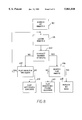
- FIG. 4 is block diagram illustrating the general flow of information and signals between the various parts of the system for updates on inmate status and monitoring of remote equipment;
- FIG. 5 is chart representing typical data base record for stored information pertaining to prisoners, victims and system audit records
- FIG. 6 is a flow chart in block diagram form depicting the main operating program used with the present invention.
- FIG. 7 is a flow chart depicting the general routine initiated by a caller for information either by inmate number or inmate name;
- FIG. 8 is a flow chart depicting an operating program initiated by a caller when requesting a search by inmate number and the response thereto;
- FIG. 8A is a flow chart of an alternate routine from that shown in FIG. 8 in which the caller is required to have a specific unique number in order to gain information about the status of an inmate;
- FIGS. 9A and 9B collectively represent a single flow chart depicting an operating program initiated by a caller when requesting a search by inmate name and the response thereto;
- FIG. 10 is a flow chart representing an operating program initiated by a caller when registering as a to-be notified-when-status-changes-caller ("victim") into the notification system with respect to a selected inmate;
- FIG. 11 is a flow chart representing an operating program initiated by system to notify a victim when the status of the selected inmate has changed.
- Callers and Registered Victims in various situations.
- “Caller” shall be defined as any person that calls the system for information about the status of an inmate.
- "Registered Victim” shall be any person who has provided the system with his or her unique identifying communication address such as a telephone number or electronic address and selected a personal identifying number, i.e., a "PIN”.
- FIGS. 1 and 1A illustrating, respectively, a schematic of the victim information and notification system ("System") used to register and notify Registered Victims and a schematic of the major components of the remote gateway and central control station.
- the System is comprised of four major components: a plurality of host computers 10; a plurality of remote gateways 12 associated with each host computer 10; a central victim call control station 14; and a plurality of notification receiving devices such as telephones 18 associated with each Caller or Registered Victim.
- the host computers 10 are physically located in the region or locality of the site shown by the dashed lines 11 in which the inmates are incarcerated or placed. Such localities shall define the term "Local Site" as used in this description.
- Computers 10 thus generally store inmate and case management information pertaining to inmates in the respective Local Site.
- host computers are mainframes such as IBM 3090, Unisys or HP mainframes although at some smaller facilities a PC based system may be employed.
- the controlling software component used in a Local Site that tracks inmates through the local criminal justice system is ordinarily chosen by the agency in charge of managing the information ("Local authorities").
- the Local authorities will determine the precise wording of information to be delivered to Callers and Registered Victims pertaining to inmates in the Local Site and the nature of the responses required of such Callers and Registered Users.
- the host computers 10 of the Local Sites are coupled via a local area network 36 to associated remote gateways 12 typically located in the same Local Site.
- Gateways 12 are primarily used to extract and filter the necessary information from the host computers 10 to deliver to the central control station 14 in a manner to be described.
- Each remote gateway 12 comprises hardware components such as a PC, a high speed modem and connection hardware as illustrated in FIG. 1A.
- the software component of the gateway 12 is responsive to provide the necessary information and calls needed by the central victim call control station 14.
- Control station 14 communicates with remote gateway 12 through long distance network 16 and houses the central processing software functioning to process the data forwarded by remote gateways 12 from host computers 10.
- the primary functions of control station 14 are to process incoming calls 20 from telephones 18 and provide information in response to such calls via the long distance network 16 and to initiate warning or notification calls 22 to the numbers or electronic addresses of telephones 18 or other communication receiving devices of Registered Victims as significant changes in inmate status information is received.
- each control station 14 typically comprises one or more central processors 14a, a high speed modem 14b, a voice recognition board 14c, and a telecommunication and voice processing board 14d. Examples of each are given in the Table 1 set forth below.
- the voice processing board 14d provides the System the ability to deliver predetermined spoken messages to registered victims while the voice recognition board provides the System the ability to process and to react to spoken commands and/or store spoken information where the Local Authorities have requested this ability as a part of the service to the Local Site.
- the System of the present invention also contemplates the use of a notification work station 24 comprising a PC and software permitting operators of the System to directly use the control station 14 to generate various reports and letters.
- a notification work station 24 comprising a PC and software permitting operators of the System to directly use the control station 14 to generate various reports and letters.
- letters 26 prepared, for example, by operators of PCs 27 networked with the central control station 14.
- Such letters are backup notices containing information with respect to the notification attempts such as when and how many notification calls were made and the notification message itself. The letters are then posted the Registered Victims who were not confirmed as being reached.
- the executive operating system 28 maintains within control station 14 a comprehensive database for each Local Site represented by a "DNIS" (defined below) as character numeral 30 and "personality" files 32 for each site.
- DNIS defined below
- personality is used to denote that each Local Site has an overall process or communication routine customized in accordance with the desires of the Local authorities for communication with Callers and Registered Victims about victims incarcerated within the Local Site.
- voice messages, prompts, PIN numbers, use of voice recognition and voice inputs, and the like vary among the various Local Sites in the System.
- the executive operating system 28 is responsible for the management of all calls, database management, collection of remote gate way information, the personality and flow of all incoming and outgoing telephone calls, and the recording of all audit files showing incoming and outgoing call activity.
- the executive operating system 28 determines the Local Site to which the incoming call pertains. All Local Sites, for example, may be assigned a specific 800number for Callers to use when requesting status information about an inmate associated with the Local Site.
- the long distance carriers send a special code to the receiving party which identifies the specific 800 number being dialed. This service is called the Dialed Number Identification Service or "DNIS”.
- Such a service provides receiving parties, who have purchased the use of a plurality of 800 numbers, the ability to determine which of the 800 numbers is being called.
- the operating system 28, using the DNIS is prompted to locate the appropriate personality file 32 for that call.
- System 28 then begins executing the located personality file 32, which defines all the messages that are played during the particular call.
- the personality file 32 also defines all of 10 the menu selections given the Caller and reads/write the various data bases used for the call.
- the inmate information that goes into the various databases is initially collected from the host computer 10 by the remote gateway 12 which, in part, comprises a PC and a high speed modem.
- the block diagram of FIG. 3 illustrates that, as each new Local Site goes into the System of the present invention, the PC of the remote gateway 12 associated with the new Local Site is connected through a local area network 36 to the associated host computer 10 and, as stated above, is able to communicate with the central control station 14 through a long distance carrier. Once connected, the remote gateway 12 then collects a complete set of initial inmate and victim data from host computer 10 and transmits the data to the control station 14.
- Callers can dial a unique 800 number (shown by character numeral 40) assigned to each Local Site and search the data bases associated with that Local Site for information on inmate status. Additionally, the Caller, if not already registered, can register as a Registered Victim for automatic notification in response to the registration request 42 communicated to the caller following delivery of the inmate status information. Individuals are made aware of the 800 number through public service announcements made in the media of the appropriate Local Site, brochures promulgated by the police of the Local Site, and other publicity as determined by the Local authorities. This publicity transaction is depicted by publicity BLOCK 44.
- remote gateway 12 makes a transaction file check 52 at predetermined intervals, e.g., every 10 minutes, with each host computer 10.
- the host computer 10 writes an audit record to a transaction file and uploads the transaction file depicted by line 54 to gateway 12.
- gateway 12 checks the transaction file for changes in inmate status. When a change is detected, gateway 12 sends the changed status depicted by line 56 to control station 14.
- Control station 14 searches databases to determine if there are any Registered Victims (denoted by BLOCK 59) that need to be notified of the changed status. In the event that such Registered Victims are identified, the notification call process (discussed below) will be automatically triggered and a notification call sequence 58 initiated.
- Registered Victims denoted by BLOCK 59
- each remote gateway 12 transmits a "handshake" signal 60 at frequent intervals, e.g., every two minutes, to control station 14.
- the signal 60 is a telephone call to a specific telephone number at control station 14 with the call carrying an automatic number identification (ANI) signal passed between telephone rings.
- ANI automatic number identification
- Such ANI signals enable the control station 14 to identify the precise remote gateway 12 making the call without making a direct connection, i.e., picking up the telephone or using separate communication channels.
- the remote gateway 12 in the Local Site is assigned a 800 number unique for that Local Site to call and the control station 14, using the DNIS, can then identify the calling remote gateway 12 by the 800 number thus being called.
- the control station 14 "knows" that the gateway 12 is operating properly and the timer for that remote gateway is reset as shown by reset BLOCK 61.
- the control station may cause an alert signal 62 to trigger an alert window of a computer screen 63 at the site of the central control station 14 alerting a viewer of the possible communication malfunction.
- the control station 14 may also send out a pager signal 64 to a pager 65, alerting an assigned repair operator of the uncommunicative remote gateway who then determines the nature and addresses the problem.
- the function block diagram of FIG. 6 describes the "updating" of the various files upon receipt of an incoming status change call 56 from remote gateway 12.
- control station 14 handshakes with the calling remote gateway 12 and verifies at VERIFY 66 that the data is coming from a legitimate source using a predetermined identifying protocol. This, of course, is needed to ensure that system is not compromised by entry of incorrect data from extraneous sources.
- the program routine stops at BLOCK 68. If YES, the System determines at BLOCK 70 whether this is a change to the victim or inmate database. If it is a change to the victim database, the victim database is updated at BLOCK 72.
- the inmate database is updated at BLOCK 74 and a determination made at NOTIFICATION 76 whether a Registered Victim associated with the particular inmate should be notified. If YES, then notification calls 78 are begun. If NO, the program ends at BLOCK 80.
- FIG. 7 The general routine executed when a Caller dials the 800 number for a Local Site is shown in FIG. 7.
- FIG. 10 is the subroutine automatically executed following delivery of the requested inmate status information during which the Caller is given the option of registering as a Registered Victim.
- the main routine is initiated at BLOCK 86 with the control station 14 through its voice processor answering the call, identifying the Local Site associated with the call via DNIS, and providing initial prompts in accordance with the personality file for that Local Site.
- the initial prompts may start by giving the Caller a choice between two of more languages in which further voice communications can proceed.
- the language choices may be English, Spanish or Vietnamese, with the voice processor stating each choice in the respective language for that choice.
- the Caller would press 1, 2, or 3 as prompted depending on the language choice.
- the System will continue to use that language when addressing the Caller, in both current and future notification calls.
- the next prompt at BLOCK 88 made in the selected language would be a request to press 1 if the Caller wishes to use an "inmate number" to initiate the search or press 2 if the Caller will use the inmate name for the search.
- Local authorities typically assign each inmate a number, i.e., the "inmate number", for use in the System.
- Caller then makes a choice selection depicted by BLOCK 90 for inmate number or BLOCK 92 for inmate name. The selection then initiates either the subroutines set forth in FIGS. 8 for inmate number or FIGS. 9A/9B for inmate name.
- the Caller is returned to the main routine and will be typically asked if he or she wishes to be registered as a Registered Victim at BLOCK 94. If the Caller responds in the affirmative to the registration inquiry prompt at BLOCK 94, then the subroutine of FIG. 10 is initiated and executed. Upon completion of the registration menu selections, the program ends in the main routine with a "Goodbye" BLOCK 96 to the caller.
- the caller When the Caller elects to search for inmate status information by inmate number as illustrated in the subroutine flow chart of FIG. 8, the caller is prompted at prompt BLOCK 98 by the voice processor to enter the inmate number or, in an alternate subroutine, a "victim number" on the touch dial phone. Since the inmate number is determined by the Local authorities, the Caller obtains the inmate number through procedures established by the Local authorities. For certain Local Sites, the authorities may desire to further limit access to the information imparted by the System. Some Local Authorities prefer not to permit use of the inmate names to gain access and limit dissemination of the inmates number on a need-to-know basis. Some Local Authorities issue the inmate numbers only to Registered Victims.
- any Caller wishing to access the System using the Local Site DNIS number would have to either register as a Registered Victim with the Local Authorities to obtain the inmate number or go through some sort of prescribed administrative procedure.
- the Local authorities may require that each Registered Victim be provided a victim notification card identification number (Victim Number) that must be entered before any information on inmates is communicated by the central control station.
- Victim Number victim notification card identification number
- control station 14 determines if the number is valid or not at determination BLOCK 100. If NO, the Caller is informed that the inmate number is not the correct number of digits at BLOCK 102 and invited to try another number or hangup. If YES, the Caller is returned to Enter Number at BLOCK 98. If No, the caller is returned to the main routine at BLOCK 104 for "Goodbye". If the inmate number has the correct number of digits at BLOCK 100 or YES, a search is made for the inmate database at BLOCK 106.
- the Caller is returned at BLOCK 108 to the main routine at BLOCK 94 where the Caller is informed of the latest status of the inmate. If NO, i.e., no inmate is found at BLOCK 110, then the Caller is informed of this fact and the routine ends with "Goodbye".
- control station determines if the Victim Number is valid or not at BLOCK 114. If NO, the Caller is informed the number is not valid and invited to re-enter the correct Victim Number at BLOCK 116. The cycle will be repeated at predetermined number of intervals, e.g., three times, after which the control station will return to the main program at the "Goodbye" statement. If YES, the control station will search for the corresponding inmate data base at BLOCK 118. If the inmate is not found or NO, the Caller is told this at BLOCK 120 and the routine ends with "Goodbye". If the corresponding inmate database is found or YES, the control station returns to the main routine at BLOCK 122 and provided the inmate status at BLOCK 94.
- control station 14 When such an election has been made, the control station 14 at BLOCK 124 requests that the Caller enter the inmate's last name. Typically, the Caller enters the last name at BLOCK 126 by spelling the name through use of the appropriate alphanumeric buttons on an available touch tone phone. Where the Local Authorities desire a voice responsive System, control station 14 has the additional capability of accepting voice spelling of the names through the voice recognition component 14c (see FIG. 1A). In either case, for confirmation, the control station 14 will generally spell back the name for the Caller at BLOCK 128 to confirm the correct entry of the name.
- An alternate version has the control station stating or pronouncing the name for confirmation when the name is "recognized" by the control station, i.e., where a voice file for that spelling is in the control station database.
- the response to the confirmation request BLOCK 128 is to press 1 (CORRECT) or 2 (INCORRECT). If the name is incorrect, the Caller will be invited to re-enter the last name at BLOCK 130. Assuming the name is correctly spelled, the computer makes a determination at BLOCK 132 whether or not there is an inmate of that name in the database. If NO, the response of voice control station at BLOCK 134 is that the information entered is either incorrect or that no inmate of that name is in custody and the routine ends with "Goodbye". If a match is made to an inmate name or YES, the control station will next ask for the spelling of the first name of the inmate at BLOCK 136.
- Entry of the first name is made as stated above with respect to the last name at BLOCK 138. Again, a confirmation prompt will be executed at BLOCK 140 with an INCORRECT name entry by the Caller prompting the request for re-entry at BLOCK 142. If no re-entry is made, then "Goodbye" is played at BLOCK 144. If the entry is CORRECT, a search is made at BLOCK 146 for inmates having the same name.
- a subroutine identical to the subroutines for the last and first names is executed for the inmate's middle initial with middle initial request made at BLOCK 148, entry at BLOCK 150, confirmation at BLOCK 152, and re-entry if INCORRECT at BLOCK 154. If CORRECT, this subroutine then searches for inmates at BLOCK 156. If an inmate is found or YES, the subroutine returns at BLOCK 158 to the main routine at BLOCK 94 (FIG. 7) where the Caller is provided with inmate status information.
- BLOCK 160 If no inmates with duplicate names are found or NO at BLOCK 146, then an inmate name search is initiated at BLOCK 160. If no inmates with that name are found or NO, then the routine ends at BLOCK 162 with the statement that no inmate of that name was found and "Goodbye". If an inmate is identified then the sub-routine returns at BLOCK 164 to the main routine at BLOCK 94 where the Caller is provided with inmate status information.
- FIG. 10 illustrates the subroutine executed once the System has provided the relevant inmate status information.
- control station 14 asks the Caller if he or she wishes to register in order that the Caller be notified if the status of the inmate should change. Entry is at BLOCK 167. The Caller is asked to press 1 or YES at BLOCK 166 for registration and any other key if NO. Pressing any other key results in a single repeat of the inmate status report and the routine ends with a "Goodbye" at BLOCK 169. The Caller also has the option of hanging up immediately after obtaining the status information. If YES, information is provided in this sequence as to how registration can be accomplished.
- the System may state a cautionary warning at BLOCK 168 to the effect that the System is provided as a service by the Authority and that the Caller/Registered Victim should not depend solely on the System for protection and that cautionary measures should always be taken as if the inmate had already been released.
- the System next asks for the Caller (now the Registered Victim) to input a telephone number at BLOCK 170 for registration of a telephone number that the System will call when relevant inmate change of status, i.e., releases or relocations, occurs. Registration takes place in the language that the Registered Victim, then a Caller, initially selected for status change information. Typically, the System requests the Registered Victim not to register telephone numbers that go into a switch board unless prior arrangements have been made to have messages sent by the System to be confirmed and given to the Registered Victim. Following registration of the telephone number, the System then requests at BLOCK 172 for the Registered Victim to select and enter a predetermined number of digits, e.g., four, as a PIN code.
- a predetermined number of digits e.g., four
- the System will inform the Registered Victim that the PIN code is a personal identification number that the System will use to confirm that the Registered Victim has been notified and, upon entry by the Registered Victim, will cause the System to stop calling the registered number.
- the PIN number does not have to be a number unique to the Registered Victim but is required to be a string of numbers of a predetermined length (typically four) selected by the Registered Victim. If the entered string at BLOCK contains the correct string length as determined at function BLOCK 174 or YES, the System will inform the Registered Victim at BLOCK 176 that registration is completed with respect to the subject inmate, cautioning the Registered Victim to place the PIN number in a convenient location and end the routine with "Goodbye".
- System determines the number of digits of the proposed PIN number is not the predetermined number or NO, then System will announce at BLOCK 178 that the selected PIN is invalid and the subroutine will start again at the BLOCK 172, advising the Registered Victim that the selected PIN code must have the proper number of digits.
- the flow chart of FIG. 11 is a typical routine followed by the System once information flows to Control station 14 from Remote Gate 12 that the status of a particular inmate has changed.
- the System searches for any Registered Victim that has registered for notification for that particular inmate and whether notification is proper for the particular status change. Once a Registered Victim has been identified, the System dials the telephone number registered for that Registered Victim in BLOCK 180 and, upon, making contact, provides a message in function BLOCK 182 appropriate for the status change such as, for example,
- the Registered Victim (or designee) then enters the PIN code in as entry function BLOCK 184.
- the System then makes the determination at BLOCK 186 whether or not the PIN code is the proper number of digits and, if NO, requests the re-entry of the PIN code in BLOCK 188. If the PIN number is again re-entered improperly, the System then hangs up and resets a timer for redialing the telephone number of the Registered Victim after a predetermined time interval has lapsed such, as for, example, 10 minutes. If YES, then the System determines whether the PIN entered matches the one registered in BLOCK 190.
- the System states in BLOCK 192 that is not the correct PIN code, hangs up, and resets the routine as above by redialing the registered phone number after the time interval has elapsed.
- the redialing of the Registered Victim's telephone for will continue at such intervals for a predetermined time period, for example, 12 hours.
- a notification letter (as discussed above with respect to FIG. 1) will be automatically addressed at BLOCK 196 to Registered Victim's address informing the Victim of the number of attempted notifications by telephone and setting forth the changed inmate status.
- YES is determined at BLOCK 190
- the System states at function BLOCK 194, that the PIN code has been confirmed, notification is complete and says "Goodbye".
Abstract
Description
TABLE 1 ______________________________________REMOTE GATEWAYS 12 PC Pentium PC with 8 MB Ram available from Dell Computers Corp. Modem 28.8 KB HS internal modem available from US Robotics as Model SportsterCENTRAL CONTROL STATION 1414 Slot Pentium industrial grade rack mount central processor available from Texas Micro Central Processor 14aHigh Speed Modem 14b 28.8 KB HS internal modem available from US Robotics as Model Sportster Voice Recognition Board 14c Voice recognition board available from Dialogic Corp. Mfg. # VR/160Voice Processing Board 14d T1 telecommunications and voice processing board available from Dialogic Corp. as Mfg # D/240SC-T1 ______________________________________
Claims (38)
Priority Applications (1)
| Application Number | Priority Date | Filing Date | Title |
|---|---|---|---|
| US08722359 US5861810C1 (en) | 1996-09-27 | 1996-09-27 | System and method for providing crime victims updated informations and emergency alert notices |
Applications Claiming Priority (1)
| Application Number | Priority Date | Filing Date | Title |
|---|---|---|---|
| US08722359 US5861810C1 (en) | 1996-09-27 | 1996-09-27 | System and method for providing crime victims updated informations and emergency alert notices |
Publications (2)
| Publication Number | Publication Date |
|---|---|
| US5861810A true US5861810A (en) | 1999-01-19 |
| US5861810C1 US5861810C1 (en) | 2001-02-27 |
Family
ID=24901523
Family Applications (1)
| Application Number | Title | Priority Date | Filing Date |
|---|---|---|---|
| US08722359 Expired - Lifetime US5861810C1 (en) | 1996-09-27 | 1996-09-27 | System and method for providing crime victims updated informations and emergency alert notices |
Country Status (1)
| Country | Link |
|---|---|
| US (1) | US5861810C1 (en) |
Cited By (29)
| Publication number | Priority date | Publication date | Assignee | Title |
|---|---|---|---|---|
| US6173284B1 (en) * | 1997-05-20 | 2001-01-09 | University Of Charlotte City Of Charlotte | Systems, methods and computer program products for automatically monitoring police records for a crime profile |
| WO2003048970A1 (en) * | 2001-12-07 | 2003-06-12 | Nokia Corporation | Method and server for providing database inquiry services |
| US20040024765A1 (en) * | 1997-07-21 | 2004-02-05 | Worldcom, Inc. | System and method for auditing and reconciliation of telephone service providers' databases with a regional or central data repository |
| US6842774B1 (en) * | 2000-03-24 | 2005-01-11 | Robert L. Piccioni | Method and system for situation tracking and notification |
| AU2002320648B2 (en) * | 2002-12-19 | 2005-05-05 | Webcodes Pty Ltd | An Offender Tracking System |
| US20080201143A1 (en) * | 2007-02-15 | 2008-08-21 | Forensic Intelligence Detection Organization | System and method for multi-modal audio mining of telephone conversations |
| US7697539B1 (en) * | 1999-04-12 | 2010-04-13 | Mindspeed Technologies, Inc. | Methods and apparatus for data communications through packet networks |
| US20100141445A1 (en) * | 2008-12-08 | 2010-06-10 | Savi Networks Inc. | Multi-Mode Commissioning/Decommissioning of Tags for Managing Assets |
| US7860222B1 (en) | 2003-11-24 | 2010-12-28 | Securus Technologies, Inc. | Systems and methods for acquiring, accessing, and analyzing investigative information |
| US20110012731A1 (en) * | 2009-07-14 | 2011-01-20 | Timothy Dirk Stevens | Wireless Tracking and Monitoring Electronic Seal |
| US20110050424A1 (en) * | 2009-08-28 | 2011-03-03 | Savi Networks Llc | Asset tracking using alternative sources of position fix data |
| US20110050397A1 (en) * | 2009-08-28 | 2011-03-03 | Cova Nicholas D | System for generating supply chain management statistics from asset tracking data |
| US20110050423A1 (en) * | 2009-08-28 | 2011-03-03 | Cova Nicholas D | Asset monitoring and tracking system |
| US20110054979A1 (en) * | 2009-08-31 | 2011-03-03 | Savi Networks Llc | Physical Event Management During Asset Tracking |
| US20110133888A1 (en) * | 2009-08-17 | 2011-06-09 | Timothy Dirk Stevens | Contextually aware monitoring of assets |
| US20110133932A1 (en) * | 2009-07-14 | 2011-06-09 | Chin Tong Tan | Security seal |
| US8098804B1 (en) * | 2002-04-29 | 2012-01-17 | Securus Technologies, Inc. | Systems and methods for call treatment using a third party database |
| US8187004B1 (en) | 2004-09-03 | 2012-05-29 | Desensi Jr Francis Joseph | System and method of education administration |
| US8432274B2 (en) | 2009-07-31 | 2013-04-30 | Deal Magic, Inc. | Contextual based determination of accuracy of position fixes |
| US9888112B1 (en) | 2002-08-08 | 2018-02-06 | Global Tel*Link Corporation | Telecommunication call management and monitoring system with voiceprint verification |
| US9923936B2 (en) | 2016-04-07 | 2018-03-20 | Global Tel*Link Corporation | System and method for third party monitoring of voice and video calls |
| US9965746B1 (en) | 2002-04-29 | 2018-05-08 | Securus Technologies, Inc. | Processor-based self-service terminals used with respect to controlled environment facilities |
| US10027797B1 (en) | 2017-05-10 | 2018-07-17 | Global Tel*Link Corporation | Alarm control for inmate call monitoring |
| US10115080B2 (en) | 2002-04-29 | 2018-10-30 | Securus Technologies, Inc. | System and method for proactively establishing a third-party payment account for services rendered to a resident of a controlled-environment facility |
| US10225396B2 (en) | 2017-05-18 | 2019-03-05 | Global Tel*Link Corporation | Third party monitoring of a activity within a monitoring platform |
| US10230838B2 (en) | 2002-08-08 | 2019-03-12 | Global Tel*Link Corporation | Telecommunication call management and monitoring system with voiceprint verification |
| US10572961B2 (en) | 2016-03-15 | 2020-02-25 | Global Tel*Link Corporation | Detection and prevention of inmate to inmate message relay |
| US10860786B2 (en) | 2017-06-01 | 2020-12-08 | Global Tel*Link Corporation | System and method for analyzing and investigating communication data from a controlled environment |
| US11600168B1 (en) | 2021-08-10 | 2023-03-07 | Motorola Solutions, Inc. | Systems to infer identities of persons of interest rapidly and alert first responders |
Citations (11)
| Publication number | Priority date | Publication date | Assignee | Title |
|---|---|---|---|---|
| US3810096A (en) * | 1972-09-14 | 1974-05-07 | Integrated Syst Co | Method and system for transmitting data and indicating room status |
| US4455548A (en) * | 1981-01-26 | 1984-06-19 | Burnett Dorothy K | Call system and methods and apparatus for operating same |
| US4980671A (en) * | 1989-04-26 | 1990-12-25 | Guardian Technologies, Inc. | Remote confinement system with timed tamper signal reset |
| US5091930A (en) * | 1989-02-08 | 1992-02-25 | Lifeline Systems, Inc. | Enhancement of a personal emergency response system |
| US5153584A (en) * | 1989-03-17 | 1992-10-06 | Cardiac Evaluation Center, Inc. | Miniature multilead biotelemetry and patient location system |
| US5170426A (en) * | 1991-09-12 | 1992-12-08 | Bell Atlantic Network Services, Inc. | Method and system for home incarceration |
| US5266944A (en) * | 1991-06-26 | 1993-11-30 | Bodyguard Technologies, Inc. | Electronic system and method for monitoring abusers for compliance with a protective order |
| US5307053A (en) * | 1992-05-22 | 1994-04-26 | Lucile A. Wills | Device and method for alerting hunters |
| US5402469A (en) * | 1989-02-18 | 1995-03-28 | Olivetti Research Limited | Carrier locating system |
| US5461390A (en) * | 1994-05-27 | 1995-10-24 | At&T Ipm Corp. | Locator device useful for house arrest and stalker detection |
| US5534851A (en) * | 1991-03-06 | 1996-07-09 | Russek; Linda G. | Alarm for patient monitor and life support equipment |
-
1996
- 1996-09-27 US US08722359 patent/US5861810C1/en not_active Expired - Lifetime
Patent Citations (12)
| Publication number | Priority date | Publication date | Assignee | Title |
|---|---|---|---|---|
| US3810096A (en) * | 1972-09-14 | 1974-05-07 | Integrated Syst Co | Method and system for transmitting data and indicating room status |
| US4455548A (en) * | 1981-01-26 | 1984-06-19 | Burnett Dorothy K | Call system and methods and apparatus for operating same |
| US5091930A (en) * | 1989-02-08 | 1992-02-25 | Lifeline Systems, Inc. | Enhancement of a personal emergency response system |
| US5402469A (en) * | 1989-02-18 | 1995-03-28 | Olivetti Research Limited | Carrier locating system |
| US5153584A (en) * | 1989-03-17 | 1992-10-06 | Cardiac Evaluation Center, Inc. | Miniature multilead biotelemetry and patient location system |
| US4980671A (en) * | 1989-04-26 | 1990-12-25 | Guardian Technologies, Inc. | Remote confinement system with timed tamper signal reset |
| US5534851A (en) * | 1991-03-06 | 1996-07-09 | Russek; Linda G. | Alarm for patient monitor and life support equipment |
| US5266944A (en) * | 1991-06-26 | 1993-11-30 | Bodyguard Technologies, Inc. | Electronic system and method for monitoring abusers for compliance with a protective order |
| US5396227A (en) * | 1991-06-26 | 1995-03-07 | Jurismonitor, Inc. | Electronic system and method for monitoring compliance with a protective order |
| US5170426A (en) * | 1991-09-12 | 1992-12-08 | Bell Atlantic Network Services, Inc. | Method and system for home incarceration |
| US5307053A (en) * | 1992-05-22 | 1994-04-26 | Lucile A. Wills | Device and method for alerting hunters |
| US5461390A (en) * | 1994-05-27 | 1995-10-24 | At&T Ipm Corp. | Locator device useful for house arrest and stalker detection |
Cited By (59)
| Publication number | Priority date | Publication date | Assignee | Title |
|---|---|---|---|---|
| US6173284B1 (en) * | 1997-05-20 | 2001-01-09 | University Of Charlotte City Of Charlotte | Systems, methods and computer program products for automatically monitoring police records for a crime profile |
| US20040024765A1 (en) * | 1997-07-21 | 2004-02-05 | Worldcom, Inc. | System and method for auditing and reconciliation of telephone service providers' databases with a regional or central data repository |
| US7263533B2 (en) * | 1997-07-21 | 2007-08-28 | Verizon Business Global Llc | System and method for auditing and reconciliation of telephone service providers' databases with a regional or central data repository |
| US20100158027A1 (en) * | 1999-04-12 | 2010-06-24 | Conexant Systems, Inc. | Methods and apparatus for data communications through packet networks |
| US7957369B2 (en) | 1999-04-12 | 2011-06-07 | Mindspeed Technologies, Inc. | Methods and apparatus for data communications through packet networks |
| US7697539B1 (en) * | 1999-04-12 | 2010-04-13 | Mindspeed Technologies, Inc. | Methods and apparatus for data communications through packet networks |
| US6842774B1 (en) * | 2000-03-24 | 2005-01-11 | Robert L. Piccioni | Method and system for situation tracking and notification |
| WO2003048970A1 (en) * | 2001-12-07 | 2003-06-12 | Nokia Corporation | Method and server for providing database inquiry services |
| US20050114301A1 (en) * | 2001-12-07 | 2005-05-26 | Vesa-Matti Jokinen | Method and server for providing database inquiry services |
| US20120099716A1 (en) * | 2002-04-29 | 2012-04-26 | Securus Technologies, Inc. | System and Method for Call Treatment Using a Third Party Database |
| US9990683B2 (en) | 2002-04-29 | 2018-06-05 | Securus Technologies, Inc. | Systems and methods for acquiring, accessing, and analyzing investigative information |
| US9965746B1 (en) | 2002-04-29 | 2018-05-08 | Securus Technologies, Inc. | Processor-based self-service terminals used with respect to controlled environment facilities |
| US9654620B2 (en) * | 2002-04-29 | 2017-05-16 | Securus Technologies, Inc. | System and method for call treatment using a third party database |
| US10115080B2 (en) | 2002-04-29 | 2018-10-30 | Securus Technologies, Inc. | System and method for proactively establishing a third-party payment account for services rendered to a resident of a controlled-environment facility |
| US8098804B1 (en) * | 2002-04-29 | 2012-01-17 | Securus Technologies, Inc. | Systems and methods for call treatment using a third party database |
| US10230838B2 (en) | 2002-08-08 | 2019-03-12 | Global Tel*Link Corporation | Telecommunication call management and monitoring system with voiceprint verification |
| US10721351B2 (en) | 2002-08-08 | 2020-07-21 | Global Tel*Link Corporation | Telecommunication call management and monitoring system with voiceprint verification |
| US9888112B1 (en) | 2002-08-08 | 2018-02-06 | Global Tel*Link Corporation | Telecommunication call management and monitoring system with voiceprint verification |
| AU2002320648B2 (en) * | 2002-12-19 | 2005-05-05 | Webcodes Pty Ltd | An Offender Tracking System |
| US7860222B1 (en) | 2003-11-24 | 2010-12-28 | Securus Technologies, Inc. | Systems and methods for acquiring, accessing, and analyzing investigative information |
| US10740861B1 (en) | 2003-11-24 | 2020-08-11 | Securus Technologies, Inc. | Systems and methods for acquiring, accessing, and analyzing investigative information |
| US8187004B1 (en) | 2004-09-03 | 2012-05-29 | Desensi Jr Francis Joseph | System and method of education administration |
| US8731934B2 (en) | 2007-02-15 | 2014-05-20 | Dsi-Iti, Llc | System and method for multi-modal audio mining of telephone conversations |
| US10853384B2 (en) | 2007-02-15 | 2020-12-01 | Global Tel*Link Corporation | System and method for multi-modal audio mining of telephone conversations |
| US20080201143A1 (en) * | 2007-02-15 | 2008-08-21 | Forensic Intelligence Detection Organization | System and method for multi-modal audio mining of telephone conversations |
| US11789966B2 (en) | 2007-02-15 | 2023-10-17 | Global Tel*Link Corporation | System and method for multi-modal audio mining of telephone conversations |
| US9552417B2 (en) | 2007-02-15 | 2017-01-24 | Global Tel*Link Corp. | System and method for multi-modal audio mining of telephone conversations |
| US10120919B2 (en) | 2007-02-15 | 2018-11-06 | Global Tel*Link Corporation | System and method for multi-modal audio mining of telephone conversations |
| US20100141445A1 (en) * | 2008-12-08 | 2010-06-10 | Savi Networks Inc. | Multi-Mode Commissioning/Decommissioning of Tags for Managing Assets |
| US8593280B2 (en) | 2009-07-14 | 2013-11-26 | Savi Technology, Inc. | Security seal |
| US9142107B2 (en) | 2009-07-14 | 2015-09-22 | Deal Magic Inc. | Wireless tracking and monitoring electronic seal |
| US8456302B2 (en) | 2009-07-14 | 2013-06-04 | Savi Technology, Inc. | Wireless tracking and monitoring electronic seal |
| US20110133932A1 (en) * | 2009-07-14 | 2011-06-09 | Chin Tong Tan | Security seal |
| US20110012731A1 (en) * | 2009-07-14 | 2011-01-20 | Timothy Dirk Stevens | Wireless Tracking and Monitoring Electronic Seal |
| US8432274B2 (en) | 2009-07-31 | 2013-04-30 | Deal Magic, Inc. | Contextual based determination of accuracy of position fixes |
| US9177282B2 (en) | 2009-08-17 | 2015-11-03 | Deal Magic Inc. | Contextually aware monitoring of assets |
| US20110133888A1 (en) * | 2009-08-17 | 2011-06-09 | Timothy Dirk Stevens | Contextually aware monitoring of assets |
| US20110050397A1 (en) * | 2009-08-28 | 2011-03-03 | Cova Nicholas D | System for generating supply chain management statistics from asset tracking data |
| US8314704B2 (en) | 2009-08-28 | 2012-11-20 | Deal Magic, Inc. | Asset tracking using alternative sources of position fix data |
| US20110050424A1 (en) * | 2009-08-28 | 2011-03-03 | Savi Networks Llc | Asset tracking using alternative sources of position fix data |
| US8514082B2 (en) | 2009-08-28 | 2013-08-20 | Deal Magic, Inc. | Asset monitoring and tracking system |
| US8334773B2 (en) | 2009-08-28 | 2012-12-18 | Deal Magic, Inc. | Asset monitoring and tracking system |
| US20110050423A1 (en) * | 2009-08-28 | 2011-03-03 | Cova Nicholas D | Asset monitoring and tracking system |
| US20110054979A1 (en) * | 2009-08-31 | 2011-03-03 | Savi Networks Llc | Physical Event Management During Asset Tracking |
| US11640644B2 (en) | 2016-03-15 | 2023-05-02 | Global Tel* Link Corporation | Detection and prevention of inmate to inmate message relay |
| US11238553B2 (en) | 2016-03-15 | 2022-02-01 | Global Tel*Link Corporation | Detection and prevention of inmate to inmate message relay |
| US10572961B2 (en) | 2016-03-15 | 2020-02-25 | Global Tel*Link Corporation | Detection and prevention of inmate to inmate message relay |
| US10277640B2 (en) | 2016-04-07 | 2019-04-30 | Global Tel*Link Corporation | System and method for third party monitoring of voice and video calls |
| US10715565B2 (en) | 2016-04-07 | 2020-07-14 | Global Tel*Link Corporation | System and method for third party monitoring of voice and video calls |
| US11271976B2 (en) | 2016-04-07 | 2022-03-08 | Global Tel*Link Corporation | System and method for third party monitoring of voice and video calls |
| US9923936B2 (en) | 2016-04-07 | 2018-03-20 | Global Tel*Link Corporation | System and method for third party monitoring of voice and video calls |
| US10027797B1 (en) | 2017-05-10 | 2018-07-17 | Global Tel*Link Corporation | Alarm control for inmate call monitoring |
| US10601982B2 (en) | 2017-05-18 | 2020-03-24 | Global Tel*Link Corporation | Third party monitoring of activity within a monitoring platform |
| US11044361B2 (en) | 2017-05-18 | 2021-06-22 | Global Tel*Link Corporation | Third party monitoring of activity within a monitoring platform |
| US11563845B2 (en) | 2017-05-18 | 2023-01-24 | Global Tel*Link Corporation | Third party monitoring of activity within a monitoring platform |
| US10225396B2 (en) | 2017-05-18 | 2019-03-05 | Global Tel*Link Corporation | Third party monitoring of a activity within a monitoring platform |
| US10860786B2 (en) | 2017-06-01 | 2020-12-08 | Global Tel*Link Corporation | System and method for analyzing and investigating communication data from a controlled environment |
| US11526658B2 (en) | 2017-06-01 | 2022-12-13 | Global Tel*Link Corporation | System and method for analyzing and investigating communication data from a controlled environment |
| US11600168B1 (en) | 2021-08-10 | 2023-03-07 | Motorola Solutions, Inc. | Systems to infer identities of persons of interest rapidly and alert first responders |
Also Published As
| Publication number | Publication date |
|---|---|
| US5861810C1 (en) | 2001-02-27 |
Similar Documents
| Publication | Publication Date | Title |
|---|---|---|
| US5861810A (en) | System and method for providing crime victims updated information and emergency alert notices | |
| US11496621B2 (en) | Telecommunication call management and monitoring system with voiceprint verification | |
| US6256515B1 (en) | Call management system for wireless telephones | |
| US6463127B1 (en) | Method and apparatus for speaker verification and minimal supervisory reporting | |
| US8098804B1 (en) | Systems and methods for call treatment using a third party database | |
| US5170426A (en) | Method and system for home incarceration | |
| US5912947A (en) | Public notification system and method | |
| US5369699A (en) | Adaptable personnel supervisory system with automatic fee collection | |
| US6801780B1 (en) | Method and apparatus for providing intelligent emergency paging | |
| US6567504B1 (en) | Automated calling system with database updating | |
| US6665380B1 (en) | Inmate messaging system and method | |
| US20030091158A1 (en) | Monitoring and communication system for stationary and mobile persons | |
| US20060020459A1 (en) | System and method for immigration tracking and intelligence | |
| US5555297A (en) | Automatic call distributor reporting system and method therefor | |
| US20020177428A1 (en) | Remote notification of monitored condition | |
| US20030070076A1 (en) | System and method for providing personal information about criminal offenders to a plurality of law enforcement agencies | |
| US6266396B1 (en) | Digital control of a security system | |
| WO2001011584A1 (en) | Method of and apparatus for individuals to maintain a trail of their well being and whereabouts | |
| US6556664B1 (en) | Public notification system and method | |
| US7039387B2 (en) | Systems, methods and computer program products for responding to AMBER alerts | |
| US20060258328A1 (en) | User defined codes for emergency calls | |
| CN100548017C (en) | To the method and system of the dynamic alarm of caller to the variation of menu structure | |
| WO1996034484A2 (en) | Remote activity monitoring system and method | |
| WO2000005869A1 (en) | Method and apparatus for speaker verification and electronic monitoring | |
| US20030151763A1 (en) | Method and device for the request of data required for the execution of operations at a technical installation |
Legal Events
| Date | Code | Title | Description |
|---|---|---|---|
| AS | Assignment |
Owner name: INTERACTIVE SYSTEMS, LLC, KENTUCKY Free format text: ASSIGNMENT OF ASSIGNORS INTEREST;ASSIGNOR:NGUYEN, YUNG T.;REEL/FRAME:008256/0488 Effective date: 19960927 |
|
| STCF | Information on status: patent grant |
Free format text: PATENTED CASE |
|
| RR | Request for reexamination filed |
Effective date: 19990629 |
|
| AS | Assignment |
Owner name: APPRISS, INC., KENTUCKY Free format text: ASSIGNMENT OF ASSIGNORS INTEREST;ASSIGNOR:INTERACTIVE SYSTEMS, LLC;REEL/FRAME:011170/0229 Effective date: 20001003 |
|
| B1 | Reexamination certificate first reexamination |
Free format text: CLAIM 23 IS CANCELLED. CLAIMS 1, 4, 7, 11, 13, 15-22, 24-27, 30-33 AND 35-38 ARE DETERMINED TO BE PATENTABLE AS AMENDED. CLAIMS 2, 3, 5, 6, 8-10, 12, 14, 28, 29 AND 34, DEPENDENT ON AN AMENDED CLAIM, ARE DETERMINED TO BE PATENTABLE. |
|
| C1 | Reexamination certificate (1st level) | ||
| FPAY | Fee payment |
Year of fee payment: 4 |
|
| FPAY | Fee payment |
Year of fee payment: 8 |
|
| AS | Assignment |
Owner name: WELLS FARGO FOOTHILL, INC., AS AGENT, MASSACHUSETT Free format text: SECURITY AGREEMENT;ASSIGNOR:APPRISS INC.;REEL/FRAME:019501/0710 Effective date: 20070628 |
|
| FPAY | Fee payment |
Year of fee payment: 12 |
|
| AS | Assignment |
Owner name: FIFTH THIRD BANK, AS AGENT, OHIO Free format text: SECURITY AGREEMENT;ASSIGNOR:APPRISS INC.;REEL/FRAME:029497/0844 Effective date: 20121217 |
|
| AS | Assignment |
Owner name: APPRISS INC., KENTUCKY Free format text: RELEASE BY SECURED PARTY;ASSIGNOR:WELLS FARGO CAPITAL FINANCE, INC., SUCCESSOR TO WELLS FARGO FOOTHILL, INC.;REEL/FRAME:029579/0992 Effective date: 20121217 |
|
| AS | Assignment |
Owner name: APPRISS INC., KENTUCKY Free format text: CORRECTIVE ASSIGNMENT TO CORRECT THE NATURE OF CONVEYANCE PREVIOUSLY RECORDED AT REEL: 034248 FRAME: 0427. ASSIGNOR(S) HEREBY CONFIRMS THE RELEASE OF SECURITY INTEREST;ASSIGNOR:FIFTH THIRD BANK, AS AGENT;REEL/FRAME:034470/0968 Effective date: 20141121 |
|
| AS | Assignment |
Owner name: APPRISS INC., KENTUCKY Free format text: RELEASE BY SECURED PARTY;ASSIGNOR:GOLUB CAPITAL MARKETS LLC (F/K/A GCI CAPITAL MARKETS LLC), AS SECOND LIEN ADMINISTRATIVE AGENT;REEL/FRAME:044274/0990 Effective date: 20171201 |
|
| AS | Assignment |
Owner name: APPRISS INC., KENTUCKY Free format text: TERMINATION OF SECURITY INTEREST IN PATENTS RECORDED AT REEL 034228, FRAME 0889;ASSIGNOR:GOLUB CAPITAL MARKETS LLC, F/K/A GCI CAPITAL MARKETS LLC, AS ADMINISTRATIVE AGENT;REEL/FRAME:049336/0284 Effective date: 20190531 |