US5822762A - Information processing device with decision circuits and partitioned address areas - Google Patents
Information processing device with decision circuits and partitioned address areas Download PDFInfo
- Publication number
- US5822762A US5822762A US08/533,965 US53396595A US5822762A US 5822762 A US5822762 A US 5822762A US 53396595 A US53396595 A US 53396595A US 5822762 A US5822762 A US 5822762A
- Authority
- US
- United States
- Prior art keywords
- address
- cache memory
- cpu
- memory unit
- access
- Prior art date
- Legal status (The legal status is an assumption and is not a legal conclusion. Google has not performed a legal analysis and makes no representation as to the accuracy of the status listed.)
- Expired - Lifetime
Links
Images


Classifications
-
- G—PHYSICS
- G06—COMPUTING; CALCULATING OR COUNTING
- G06F—ELECTRIC DIGITAL DATA PROCESSING
- G06F12/00—Accessing, addressing or allocating within memory systems or architectures
- G06F12/02—Addressing or allocation; Relocation
- G06F12/08—Addressing or allocation; Relocation in hierarchically structured memory systems, e.g. virtual memory systems
- G06F12/0802—Addressing of a memory level in which the access to the desired data or data block requires associative addressing means, e.g. caches
- G06F12/0888—Addressing of a memory level in which the access to the desired data or data block requires associative addressing means, e.g. caches using selective caching, e.g. bypass
Definitions
- the present invention generally relates to an information processing device equipped with a cache memory used by a central processing unit (CPU).
- Examples of such an information processing device are a microprocessor and a microcomputer.
- FIG. 1 is a block diagram of a first conventional information processing device, which is made up of a CPU 1, an address bus 2 for transferring an address signal output by the CPU 1, and a cache memory 3 used by the CPU 1.
- the cache memory 3 is equipped with a hit/miss decision circuit 4 which determines whether an access to the cache memory 3 from the CPU 1 is a cache hit or a cache miss.
- An address bus 5 for transferring an address signal for an external address output from the cache memory 3 extends from the cache memory 3.
- An external access request signal line 6 which transfers an external access request signal output from the cache memory 3 extends from the cache memory 3.
- a control register for an external resource which may be a DMA (Direct Memory Access) controller, is designed so that the contents thereof can be changed without the CPU 1. Hence, it is difficult to ensure coherency to the cache memory 3.
- an address area in which information that cannot be written into the cache memory 3 by an instruction access by the CPU 1 is stored is defined as a non-cachable area.
- the control register for an external resource is defined as the non-cachable area.
- the cache memory 3 is configured so as to refer to an address tag rather than determine whether an access from the CPU 1 is directed to the non-cachable area. Hence, when it is determined that the access is addressed to the non-cachable area, the access is determined as the cache miss in the cache memory 3, and thereafter an external access is carried out.
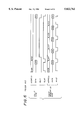
- FIG. 2 is a timing chart of an operation in the case where an access to the cache memory 3 by the CPU 1 is addressed to a non-cachable area in the cache memory 3.
- Part (A) of FIG. 2 shows clock signals ⁇ 1 and ⁇ 2 having respective phases and serving as operation clocks.
- Part (B) of FIG. 2 shows a cache access address output to the cache memory 3 from the CPU 1.
- Part (C) of FIG. 2 shows an address tag look-up operation in the cache memory 3 in which a high level corresponds to the active state).
- Part (D) of FIG. 2 shows an external access address output from the cache memory 3, and part (E) thereof shows an external access request signal output from the cache memory 3 (a high level thereof is the active level).
- the cache access address is output to the cache memory 3 from the CPU 1.
- the address tag regarding the cache access address is looked up in the cache memory 3 without determining whether the access from the CPU 1 is addressed to the non-cachable area. If the access from the CPU 1 is addressed to the non-cachable area, the hit/miss decision circuit 4 determines that the access is a cache miss. Then, the external access address for accessing an external memory is output from the cache memory 3, and the external address request signal for requesting an access to the external memory is switched to the high level.
- the access to the non-cachable area in the cache memory 3 from the CPU 1 is processed so that the hit/miss decision circuit 4 determines that the access is a cache miss and thereafter the external access is performed.
- FIG. 3 is a block diagram of a second conventional information processing device, which includes a CPU 8, an address bus 9 for transferring an address signal output by the CPU 8, and a cache memory unit 10 used by the CPU 8.
- the cache memory unit 10 is equipped with a hit/miss decision circuit which the access from the CPU 8 is a cache hit or a cache miss.
- the cache memory unit 10 is further equipped with a cachable area/non-cachable area decision circuit 12.
- the circuit 12 has the function of determining in which one of address areas among address areas partitioned beforehand the address area of the access requested by the CPU 8 falls.
- the circuit 12 has the function of determining whether the address area of the access requested by the CPU 8 is a cachable area by referring to a cachable area/non-cachable area indicating register (not shown) which has data indicating whether the address area of the access requested by the CPU 8 is a cachable area.
- the cache memory unit 10 has an OR circuit 13, which performs an OR operation on the output signal of the hit/miss decision circuit 11 and the output signal of the decision circuit 12.
- the hit/miss decision circuit 11 switches its output signal to a low level when the access from the CPU 8 is a cache hit, and switches the output signal to the high level when the access is a cache miss.
- the decision circuit 12 switches its output signal to the low level when the access from the CPU 8 is addressed to the cachable area, and switches the output signal to the high level when the access is addressed to the non-cachable area.
- the cache memory unit 10 determines whether the access from the CPU 8 is a cache hit and whether the above access is addressed to the cachable area.
- An address bus 14 that transfers the address signal for an external address output from the cache memory unit 10 extends from the cache memory unit 10.
- An external access request signal line 15 that transfers an external access request signal output from the cache memory unit 10 extends from the cache memory unit 10.
- FIG. 4 is a timing chart of an operation in a case where an access to the cache memory unit 10 by the CPU 8 is addressed to a non-cachable area in the second conventional device.
- Part (A) of FIG. 4 shows clock signals ⁇ 1 and ⁇ 2 having respective phases and serving as operation clocks.
- Part (B) of FIG. 4 shows a cache access address output to the cache memory 3 from the CPU 1.
- Part (C) of FIG. 4 shows an address tag look-up operation in the cache memory 3 in which a high level corresponds to the active state).
- Part (D) of FIG. 4 shows an address area decision operation on the access requested by the CPU 8, the operation being performed in the cache memory unit 10 (the high level of the signal shown in part (D) is the active state).
- Part (E) of FIG. 4 shows a cachable area/non-cachable area indicating register loop-up operation in the cache memory unit 10 (the high level of the signal shown in part (E) is the active state).
- Part (F) of FIG. 4 shows the external access address output from the cache memory unit 10.
- Part (G) of FIG. 4 shows the external access request signal output from the cache memory unit 10 (the high level is the active level).
- the CPU 8 When the CPU 8 accesses the cache memory unit 10, the CPU 8 outputs the cache access address to the cache memory unit 10.
- the decision circuit 12 in the cache memory unit 10 makes a decision on the address area of the access requested by the CPU 8. Subsequently, the cachable area/non-cachable area indicating register 12 is referred to, and the address area accessed by the CPU 8 is addressed to the cachable area. Further, in the cache memory unit 10, the address tag is looked up independently of the decision operation on the accessed address area and the register loop-up operation.
- the decision circuit 12 determines that the access from the CPU 8 is addressed to the non-cachable area, the output of the decision circuit 12 is switched to the high level before the hit/miss decision circuit 11 switches its output signal to the high level.
- the external access address for an external access is output from the cache memory unit 10, and the external access request signal is switched to the high level.
- the access to the non-cachable area from the CPU 8 can be determined as an access to the non-cachable area by means of the decision circuit 12 1/2 cycle before the access is determined as a cache miss by means of the hit/miss decision circuit 11.
- the external access can be advanced by 1/2 cycle.
- FIG. 5 is a block diagram of a third conventional device, which includes a CPU 17, address buses 18 and 19, data buses 20 and 21, a cache memory unit 22 having a block transfer function, and a peripheral circuit 24 which may be a serial I/O.
- a main memory 23 is connected, as an external device, to the information processing device.
- the block transfer function transfers a group of blocks, e.g., four blocks at one time.
- the requested data is transferred to the CPU 17 from the cache memory unit 22 via the data bus 20 if the requested data is in the cache memory unit 22 (in the case of cache hit). If the requested data is not in the cache memory unit 22 (in the case of cache miss), a block transfer of data is performed.
- FIG. 6 is a timing chart of the block transfer operation of the third conventional device.
- FIGS. 7 and 8 are block diagrams of the block transfer operation of the third conventional device. These figures relate to a case where a read access to the cache memory unit 22, for example, address A00, while data D00 is not present at address A00 of the cache memory unit 22.
- the read access to address A00 is given to the main memory 23 by the CPU 17.
- data D00 of address A00 is output from the main memory 23 and transferred to the cache memory unit 22 and the CPU 17.
- read accesses to addresses A01, A02 and A03 are sequentially performed from the cache memory unit 22 to the main memory 23, and data D01, D02 and D03 of addresses A01, A02 and A03 are transferred to the cache memory unit 22.
- the CPU 17 is in the waiting state until data D00 related to the data read request issued for itself.
- data D00 is transferred and received, the CPU 17 proceeds with an operation on data D00 in parallel with the block transfer operation in the cache memory unit 22.
- the external access is not allowed until the loop-up operation of the address tag is completed and the access is determined as a cache miss when the CPU 1 accesses a non-cachable area in the cache memory unit 3. Hence, it takes a long time to start the external access. Further, the address tag is referred to each time the CPU 1 accesses the cache memory unit 3. This leads to an increase in power consumption.
- the external access can be started by 1/2 cycle when an access to the cache memory unit 10 by the CPU 8 is addressed to a non-cachable area.
- the address area indicated by the access request by the CPU 8 is started after the cache access address from the CPU 8 is received.
- the interval between the completion of the cachable area/non-cachable area indication register look-up operation and the start of the external access operation therefore becomes a critical path, which prevents speeding-up of the operation of the device.
- the address tag is referred to each time the CPU 8 accesses the cache memory unit 10, as in the case of the first device. This leads to an increase in power consumption.
- the problems of the third device are as follows.
- the operation on data D00 in the CPU 17 and the block transfer of data D01, D02 and D03 from the main memory 23 to the cache memory unit 22 are concurrently carried out.
- the address bus 19 and the data bus 21 are occupied by the cache memory unit 22.
- address A10 is output by the CPU 17 as shown in FIG. 6.
- the CPU 17 cannot be allowed to access the peripheral circuit 24 until the block transferring of data D01, D02 and D03 from the main memory 23 to the cache memory unit 22 is completed. Hence, it takes a long time to obtain data D10 via the peripheral circuit 24 and hence the processing speed is reduced.
- a more specific object of the present invention is to provide an information processing device capable of operating at a higher speed.
- an information processing device comprising:
- a second decision circuit which determines whether the above one of the partitioned address areas is a cachable area or a non-cachable area before address tag data is referred to in the cache memory unit.
- the first decision circuit is provided in the central processing unit; and the second decision circuit is provided in the cache memory unit.
- the first decision circuit and the second decision circuit are provided in the cache memory unit.
- an information processing device comprising:
- a cache memory unit having a block transfer function in which blocks of data are transferred
- peripheral circuit connected to an address bus and a data bus, which connect the central processing unit and the cache memory unit together.
- the cache memory unit includes a plurality of memory parts, each of which can be set to either a cache memory mode or a RAM mode.
- FIG. 1 is a block diagram of a first conventional information processing device
- FIG. 2 is a timing chart of an operation of the first device shown in FIG. 1;
- FIG. 3 is a block diagram of a second conventional information processing device
- FIG. 4 is a timing chart of an operation of the second device shown in FIG. 1;
- FIG. 5 is a block diagram of a third conventional information processing device
- FIG. 6 is a timing chart of an operation of the third device shown in FIG. 5;
- FIGS. 7 and 8 are block diagrams of a block transfer operation of the third device shown in FIG. 5;
- FIG. 9 is a block diagram of an information processing device according to a first embodiment of the present invention.
- FIG. 10 is a timing chart of an operation of the information processing device shown in FIG. 9;
- FIG. 11 is a timing chart of another operation of the information processing device shown in FIG. 9;
- FIG. 12 is a block diagram of an information processing device according to a second embodiment of the present invention.
- FIG. 13 is a block diagram of an operation of the information processing device shown in FIG. 12;
- FIGS. 14 and 15 are block diagrams showing a block transfer operation of the information processing device shown in FIG. 12;
- FIG. 16 is a block diagram of an information processing device according to a third embodiment of the present invention.
- FIG. 17 is a block diagram of a mode setting in which a first memory part shown in FIG. 16 is set to a cache memory mode;
- FIG. 18 is a block diagram of a mode setting in which the first memory part shown in FIG. 16 is set to a RAM mode;
- FIG. 19 is a block diagram of a peripheral circuit for the first memory part
- FIG. 20 is a block diagram of an operation of the information processing device shown in FIG. 16;
- FIG. 21 is a block diagram of an information processing device according to a fourth embodiment of the present invention.
- FIG. 22 is a block diagram of an operation of the information processing device shown in FIG. 21.
- the information processing device shown in FIG. 9 includes a CPU 26 and an address bus 27 which transfers an address signal output by the CPU 26.
- the CPU 26 has accessed address area decision unit 28, which can be implemented by hardware or software.
- the entire address area is partitioned in a predetermined number of parts. In the following description of the first embodiment of the present invention, the entire address area is partitioned in eight address areas.
- the decision unit 28 determines to which one of the eight address areas the access by the CPU 26 belongs.
- An accessed address area decision signal line 29 extends from the decision unit 28 in the CPU 26, and carries an accessed address area decision signal NCA, which consists of three bits and indicates the address area accessed by the CPU 26.
- the device shown in FIG. 9 includes a cache memory unit 30 used by the CPU 26, which includes a hit/miss decision circuit 31.
- the circuit 31 determines whether the access by the CPU 26 is a cache hit or a cache miss.
- the hit/miss decision circuit 31 outputs "0" (which corresponds to a low level) in the case of the cache hit, and outputs "1" (which corresponds to a high level) in the case of the cache miss.
- the cache memory unit 30 includes a cachable area/non-cachable area decision circuit 32, which determines the access by the CPU 26 is addressed to a cachable area.
- the cachable area/non-cachable area decision circuit 32 includes a cachable area/non-cachable area indication register 33, which each of the partitioned address areas is a cachable area or non-cachable area.
- the entire address area is partitioned in eight address areas.
- the first address area is permanently defined as a non-cachable area according to the specification, and the second to eighth address areas can be respectively defined as either cachable or non-cachable areas by the users.
- the cachable area/non-cachable area indication register 33 has seven one-bit registers 34 1 -34 7 related to the second to eighth address areas.
- the one-bit registers 34 1 -34 7 respectively indicate whether the second to eighth address areas are cachable areas.
- the cachable area is indicated by "1"
- the non-cachable area is indicated by "0".
- the decision circuit 32 includes a selector 35, which selects one of the seven one-bit registers 34 1 -34 7 in accordance with the accessed address area decision signal NCA supplied from the CPU 26.
- the relation between the value of the three-bit signal NCA and one of the seven registers 34 1 -34 7 to be selected is defined in Table 1.
- the cache memory unit 30 includes an OR circuit 36, which performs an OR operation on the output signal of the hit/miss decision circuit 31 and the output of the cachable area/non-cachable area decision circuit 32, that is, the output of the selector 35, and produce a resultant external access request signal.
- An address bus 37 extends from the cache memory unit 30, and carries the address signal for an external access output from the cache memory unit 30.
- An external access request signal line 36 extends from the cache memory unit 30, and carries the external access request signal output from the cache memory unit 30.
- FIG. 10 is a timing chart of an operation performed when an access to the cache memory unit 30 by the CPU 26 is addressed to a non-cachable area.
- Part (A) of FIG. 10 shows clock signals ⁇ 1 and ⁇ 2 having respective phases and serving as operation clocks.
- Part (B) of FIG. 10 shows an accessed address area decision operation by the CPU 26.
- Part (C) of FIG. 10 shows the cache access address output by the CPU 26.
- Part (D) of FIG. 10 shows the cachable area/non-cachable area indication register look-up operation (the high level thereof indicates the active state), and part (E) thereof shows the external access address output from the cache memory unit 30.
- part (F) of FIG. 10 shows the external access request signal output from the cache memory unit 30.
- FIG. 11 is a timing chart of an operation performed when an access to the cache memory unit 30 by the CPU 26 is addressed to a cachable area and becomes a cache miss. More particularly, (A) of FIG. 11 shows clock signals ⁇ 1 and ⁇ 2 having respective phases and serving as operation clocks. Part (B) of FIG. 11 shows an accessed address area decision operation by the CPU 26. Part (C) of FIG. 11 shows the cache access address output by the CPU 26. Part (D) of FIG. 11 shows the cachable area/non-cachable area indication register look-up operation (the high level thereof indicates the active state), and part (E) thereof shows an address tag look-up operation (the high level thereof indicates the active state). Part (F) of FIG. 11 shows the external access address output from the cache memory unit 30. Further, part (G) of FIG. 11 shows the external access request signal output from the cache memory unit 30.
- the accessed address area decision circuit 28 makes a decision on the address area accessed by the CPU 26 before accessing. Thereafter, the CPU 26 outputs the cache access address to the cache memory unit 30, and outputs the accessed address area decision signal NCA indicating the accessed address area to the selector 35 of the cache memory unit 30.
- the cache access address is received, and it is determined whether the accessed address area is a cachable area by referring to the cachable area/non-cachable area indication register 33.
- the step of determining whether the accessed address area is a cachable area is as follows. When the signal NCA is 000!, "0" is output from the selector 35. When the signal NCA is one of 001!- 111!, the selector 35 outputs the indication data read from a corresponding one of the one-bit registers 34 1 -34 7 indicated by the signal NCA supplied from the CPU 26.
- the address tag look-up operation is carried out, and the access request is a cache miss.
- the external access address for accessing the external memory is output from the cache memory unit 30, and the external access request signal for requesting an access to the external memory is switched to "1" (high level).
- the CPU 26 makes a decision on the address area to be accessed before accessing the cache memory unit 30.
- the cache memory unit 30 can determine whether the accessed address area is a cachable area immediately upon receipt of the accessed address area indication signal NCA supplied at the same time as the cache access address.
- the interval between the completion of the cachable area/non-cachable area indication register look-up operation and the start of the external access operation does not become a critical path, which prevents speeding-up of the operation.
- the address tag is not referred to when an access to the cache memory unit 30 by the CPU 26 is addressed to a non-cachable area, and hence power consumption can be reduced.
- the cachable area/non-cachable area decision circuit 32 is provided in the cache memory unit 30.
- FIG. 12 shows such an information processing device, which includes the CPU 17, the cache memory unit 22 and the peripheral circuit 24.
- This peripheral circuit 24 connected to the address bus 18 and the data bus 20.
- FIG. 13 is a timing chart of the block transfer operation of the cache memory unit 22 according to the second embodiment of the present invention.
- FIGS. 14 and 15 also show the block transfer operation.
- FIGS. 13, 14 and 15 relate to a case where data D00 is not indicated by address A00 in the cache memory unit 22, when a read access to address A00 of the cache memory unit 22 is requested by the CPU 17.
- the read access to address A00 of the main memory 23 through the cache memory unit 22 is given by the CPU 17, as shown in FIGS. 13 and 14.
- data D00 one block data specified by address A00 is read from the main memory 23 and transferred to the cache memory unit 22 and the CPU 17.
- FIGS. 13 and 15 the read accesses to addresses A01, A02 and A03 of the main memory 23 from the cache memory unit 22 are sequentially carried out, and block data D01, D02 and D03 respectively specified by addresses A01, A02 and A03 are sequentially transferred to the cache memory unit 22 from the main memory 23.
- the CPU 17 is in the waiting state until data D00 requested for itself is received.
- the CPU 17 can process data D00 while the block transfer of data D01, D02 and D03 is being performed.
- the CPU 17 If the CPU 17 needs a read access to address A10 of the peripheral circuit 24, the CPU 17 outputs address A10 even during the block transfer operation on data D01, D02 and D03. In response to address A10, corresponding data D10 is output from the peripheral circuit 24 and is transferred to the CPU 17.
- the peripheral circuit 24 may be a serial interface or a timer.
- the peripheral circuit 24 is connected to the address bus 18 and the data bus 20 connecting the CPU 17 and the cache memory 22 together. Hence, it is possible for the CPU 17 to access the peripheral circuit 24 and process data obtained therefrom even while data D01, D02 and D03 are being transferred to the cache memory unit 22 by the block transfer process. Hence, it is possible to speed up the operation of the CPU 17.
- FIG. 16 shows such an information processing device, which includes a CPU 40, address buses 41 and 42, data buses 43 and 44, and a cache memory unit 45 having a two-way set associative structure.
- a main memory 46 is connected, an external device, to the information processing device.
- the cache memory unit 45 includes a first memory part 48 and a second memory part 49, which can be independently set to a cache memory mode or a RAM mode. That is, each of the first and second memory parts 48 and 49 can operate as a cache memory or a RAM.
- the cache memory unit 45 includes an address generating circuit 50 and a bus switching circuit 51.
- the bus switching circuit 51 includes address bus switching circuits 52-54, and data bus switching circuits 55-57.
- FIG. 17 is a block diagram of a peripheral part of the first memory part 48 related to the cache memory mode.
- the peripheral part shown in FIG. 17 includes a comparator circuit 59, which compares 22 upper bits A31-A10 among 32 CPU address bits A31-A0 supplied from the CPU 40 with address tag data stored in the first memory part 48. The comparison result is a hit/miss decision signal.
- Eight lower address bits A7-A0 among the CPU address bits A31-A0 are applied to the first memory part 48, so that one of the blocks can be selected.
- the address bits A9 and A8 select data among a group of data in the selected block.
- the hit/miss decision signal indicates "1". If not, the hit/miss decision signal indicates "0". In the case of the cache hit, a data line of 32 bits extends from the first memory part 48.
- FIG. 18 is a block diagram of a peripheral part of the first memory part 48 related to the RAM mode.
- the peripheral part shown in FIG. 18 includes a RAM address memory circuit 60 and a RAM area access decision circuit 61.
- the RAM address memory circuit 60 stores the 22 upper bits of the 32-bit RAM address related to the first memory part 48.
- the RAM area access decision circuit 61 compares the 22 upper bits A31-A10 of the CPU address bits A31-A0 with the RAM address stored in the RAM address memory circuit 60 in order to determine whether the access by the CPU 40 is addressed to a RAM area. The comparison result serves as a RAM area access decision signal.
- the eight lower address bits A7-A0 of the 32-bit CPU address are used to select one of the blocks, and the address bits A9 and A8 are used to specify data in the data group in the selected block.
- the 22 upper bits A31-A10 are compared with the RAM address stored in the RAM address memory circuit 60. When the access by the CPU 40 is the RAM area, the RAM area access decision signal indicates "1". When the access by the CPU 40 is not the RAM area, the RAM area access decision signal indicates "0".
- a selector 62 selects either the comparator circuit 59 or the decision circuit 61 in accordance with a select bit stored in a register 63 by the user.
- the selected signal controls the bus switching circuit 55.
- the register 63 store other user writable select bits which control the other switching circuits 52, 53, 54, 56 and 57.
- Each of the switching circuits 52-57 can be formed by, for example, tri-state buffers.
- FIG. 20 is a block diagram showing a mode setting in which the first memory part 48 is set to the cache memory mode and the second memory part 49 is set to the RAM mode.
- the address bus switching circuits 52 and 54 connects the address bus 42 to the first memory part 48, and the address bus switching circuit 53 connects the address bus 41 to the second memory part 49.
- the data bus switching circuits 55 and 57 connect the data bus 44 to the first memory part 48, and the data bus switching circuit 56 connects the data bus 43 to the second memory part 49.
- the CPU 40 is connected to the second memory part 49 via the address bus 41 and the data bus 43.
- the first memory part 48 is connected to the main memory 46 and the peripheral circuit 47 via the address bus 42 and the data bus 44.
- the CPU 40 can perform the RAM access to the first memory part 48 while the second memory part 49 is performing the block transfer operation from the main memory 46.
- the RAM access to the memory part set to the RAM mode even when the memory part set to the cache memory mode is performing the memory transfer operation. Hence, it is possible to speed up the process.
- FIG. 21 A description will now be given, with reference to FIG. 21, of an information processing device according to a fourth embodiment of the present invention.
- the information processing device shown in FIG. 21 is configured so that the peripheral circuit 47 is connected to the address bus 41 and the data bus 43.
- the other parts of the device shown in FIG. 21 are the same as those of the third embodiment of the present invention.
- FIG. 22 is a block diagram showing a mode setting in which the first memory part 48 is set to the cache memory mode and the second memory part 49 is set to the RAM mode.
- the address bus switching circuits 52 and 54 connect the address bus 42 to the first memory part 48
- the address bus switching circuit 53 connects the address bus 41 to the second memory part 49.
- the data bus switching circuits 55 and 57 connect the data bus 44 to the first memory part 48
- the data bus switching circuit 56 connects the data bus 43 to the second memory part 49.
- the CPU 40 is coupled to the peripheral circuit 47 and the second memory part 49 via the address bus 41 and the data bus 43, and the first memory part 48 is coupled to the main memory 46 via the address bus 42 and the data bus 44.
- the CPU 40 can perform the RAM access to the second memory part 49 of the cache memory 45 or the access to the peripheral circuit 47 even when the first memory part 48 of the cache memory 45 is performing the block transfer from the main memory 46.
- the CPU 40 can perform the RAM access to the first memory part 48 or the access to the peripheral circuit 47.
- the RAM access to the memory part set to the RAM mode or the access to the peripheral circuit 47 can be performed even when the memory part set to the cache memory mode is performing the block transfer operation.
Abstract
Description
              TABLE 1
______________________________________
NCA     ONE-BIT REGISTER TO BE SELECTED
______________________________________
000     ("0" is output)
001     register 34.sub.1
010     register 34.sub.2
011     register 34.sub.3
100     register 34.sub.4
101     register 34.sub.5
110     register 34.sub.6
111     register 34.sub.7
______________________________________
Claims (3)
Priority Applications (1)
| Application Number | Priority Date | Filing Date | Title |
|---|---|---|---|
| US09/074,317 US6535960B1 (en) | 1994-12-12 | 1998-05-08 | Partitioned cache memory with switchable access paths |
Applications Claiming Priority (2)
| Application Number | Priority Date | Filing Date | Title |
|---|---|---|---|
| JP6-307230 | 1994-12-12 | ||
| JP30723094A JP3724001B2 (en) | 1994-12-12 | 1994-12-12 | Information processing device |
Related Child Applications (1)
| Application Number | Title | Priority Date | Filing Date |
|---|---|---|---|
| US09/074,317 Division US6535960B1 (en) | 1994-12-12 | 1998-05-08 | Partitioned cache memory with switchable access paths |
Publications (1)
| Publication Number | Publication Date |
|---|---|
| US5822762A true US5822762A (en) | 1998-10-13 |
Family
ID=17966609
Family Applications (2)
| Application Number | Title | Priority Date | Filing Date |
|---|---|---|---|
| US08/533,965 Expired - Lifetime US5822762A (en) | 1994-12-12 | 1995-09-26 | Information processing device with decision circuits and partitioned address areas |
| US09/074,317 Expired - Lifetime US6535960B1 (en) | 1994-12-12 | 1998-05-08 | Partitioned cache memory with switchable access paths |
Family Applications After (1)
| Application Number | Title | Priority Date | Filing Date |
|---|---|---|---|
| US09/074,317 Expired - Lifetime US6535960B1 (en) | 1994-12-12 | 1998-05-08 | Partitioned cache memory with switchable access paths |
Country Status (3)
| Country | Link |
|---|---|
| US (2) | US5822762A (en) |
| JP (1) | JP3724001B2 (en) |
| KR (1) | KR100296368B1 (en) |
Cited By (7)
| Publication number | Priority date | Publication date | Assignee | Title |
|---|---|---|---|---|
| US6044441A (en) * | 1995-09-29 | 2000-03-28 | Intel Corporation | Method and apparatus for encoding valid and invalid states in a cache with an invalid pattern |
| US20060161657A1 (en) * | 2002-04-29 | 2006-07-20 | Microsoft Corporation | Peer-to peer name resolution protocol (PNRP) security infrastructure and method |
| US20070046681A1 (en) * | 2005-08-23 | 2007-03-01 | Canon Kabushiki Kaisha | Memory apparatus and memory control method |
| USRE43798E1 (en) | 1995-10-10 | 2012-11-06 | Microunity Systems Engineering, Inc. | Configurable cache allowing cache-type and buffer-type access |
| US8683182B2 (en) | 1995-08-16 | 2014-03-25 | Microunity Systems Engineering, Inc. | System and apparatus for group floating-point inflate and deflate operations |
| US20150032992A1 (en) * | 2013-07-29 | 2015-01-29 | Infineon Technologies Ag | Data processing arrangement and method for data processing |
| US11281581B2 (en) * | 2020-04-16 | 2022-03-22 | SK Hynix Inc. | Memory system |
Families Citing this family (5)
| Publication number | Priority date | Publication date | Assignee | Title |
|---|---|---|---|---|
| US6769046B2 (en) * | 2000-02-14 | 2004-07-27 | Palmchip Corporation | System-resource router |
| US8751753B1 (en) | 2003-04-09 | 2014-06-10 | Guillermo J. Rozas | Coherence de-coupling buffer |
| US7636815B1 (en) * | 2003-04-09 | 2009-12-22 | Klaiber Alexander C | System and method for handling direct memory accesses |
| KR100595632B1 (en) * | 2003-12-17 | 2006-06-30 | 엘지전자 주식회사 | Method for controlling display data of mobile terminal |
| US7971002B1 (en) | 2005-04-07 | 2011-06-28 | Guillermo Rozas | Maintaining instruction coherency in a translation-based computer system architecture |
Citations (10)
| Publication number | Priority date | Publication date | Assignee | Title |
|---|---|---|---|---|
| US4899275A (en) * | 1985-02-22 | 1990-02-06 | Intergraph Corporation | Cache-MMU system |
| JPH0245846A (en) * | 1988-08-06 | 1990-02-15 | Mitsubishi Electric Corp | Data processing system |
| US5091850A (en) * | 1987-09-28 | 1992-02-25 | Compaq Computer Corporation | System for fast selection of non-cacheable address ranges using programmed array logic |
| US5157774A (en) * | 1987-09-28 | 1992-10-20 | Compaq Computer Corporation | System for fast selection of non-cacheable address ranges using programmed array logic |
| JPH0528040A (en) * | 1991-07-18 | 1993-02-05 | Oki Electric Ind Co Ltd | Quick memory access system |
| US5255384A (en) * | 1985-02-22 | 1993-10-19 | Intergraph Corporation | Memory address translation system having modifiable and non-modifiable translation mechanisms |
| US5327545A (en) * | 1988-05-26 | 1994-07-05 | International Business Machines Corporation | Data processing apparatus for selectively posting write cycles using the 82385 cache controller |
| US5561814A (en) * | 1993-12-22 | 1996-10-01 | Intel Corporation | Methods and apparatus for determining memory operating characteristics for given memory locations via assigned address ranges |
| US5586296A (en) * | 1992-12-02 | 1996-12-17 | International Business Machines Corporation | Cache control system and method for selectively performing a non-cache access for instruction data depending on memory line access frequency |
| US5625793A (en) * | 1991-04-15 | 1997-04-29 | International Business Machines Corporation | Automatic cache bypass for instructions exhibiting poor cache hit ratio |
Family Cites Families (10)
| Publication number | Priority date | Publication date | Assignee | Title |
|---|---|---|---|---|
| US3705388A (en) * | 1969-08-12 | 1972-12-05 | Kogyo Gijutsuin | Memory control system which enables access requests during block transfer |
| UST915002I4 (en) * | 1972-10-13 | 1973-10-09 | Response to chan | |
| US4084234A (en) * | 1977-02-17 | 1978-04-11 | Honeywell Information Systems Inc. | Cache write capacity |
| US4438490A (en) | 1981-10-01 | 1984-03-20 | Honeywell Information Systems Inc. | Clock control of a central processing unit from a monitor interface unit |
| JPS6467652A (en) | 1987-09-09 | 1989-03-14 | Toshiba Corp | Cache memory eliminating data discordance |
| JPH02100740A (en) | 1988-10-07 | 1990-04-12 | Nec Corp | Block loading operation system for cache memory unit |
| JPH02148149A (en) | 1988-11-29 | 1990-06-07 | Shikoku Nippon Denki Software Kk | Memory system |
| JPH04211880A (en) | 1990-02-16 | 1992-08-03 | Hitachi Ltd | One chip microprocessor and its bus system |
| JPH0520188A (en) | 1991-07-10 | 1993-01-29 | Nec Corp | Cache controller |
| US5221713A (en) | 1991-10-07 | 1993-06-22 | Rohm And Haas Company | Co-microagglomeration of emulsion polymers (encapsulated core/shell additives for pvc) |
-
1994
- 1994-12-12 JP JP30723094A patent/JP3724001B2/en not_active Expired - Lifetime
-
1995
- 1995-09-26 US US08/533,965 patent/US5822762A/en not_active Expired - Lifetime
- 1995-10-18 KR KR1019950035896A patent/KR100296368B1/en not_active IP Right Cessation
-
1998
- 1998-05-08 US US09/074,317 patent/US6535960B1/en not_active Expired - Lifetime
Patent Citations (10)
| Publication number | Priority date | Publication date | Assignee | Title |
|---|---|---|---|---|
| US4899275A (en) * | 1985-02-22 | 1990-02-06 | Intergraph Corporation | Cache-MMU system |
| US5255384A (en) * | 1985-02-22 | 1993-10-19 | Intergraph Corporation | Memory address translation system having modifiable and non-modifiable translation mechanisms |
| US5091850A (en) * | 1987-09-28 | 1992-02-25 | Compaq Computer Corporation | System for fast selection of non-cacheable address ranges using programmed array logic |
| US5157774A (en) * | 1987-09-28 | 1992-10-20 | Compaq Computer Corporation | System for fast selection of non-cacheable address ranges using programmed array logic |
| US5327545A (en) * | 1988-05-26 | 1994-07-05 | International Business Machines Corporation | Data processing apparatus for selectively posting write cycles using the 82385 cache controller |
| JPH0245846A (en) * | 1988-08-06 | 1990-02-15 | Mitsubishi Electric Corp | Data processing system |
| US5625793A (en) * | 1991-04-15 | 1997-04-29 | International Business Machines Corporation | Automatic cache bypass for instructions exhibiting poor cache hit ratio |
| JPH0528040A (en) * | 1991-07-18 | 1993-02-05 | Oki Electric Ind Co Ltd | Quick memory access system |
| US5586296A (en) * | 1992-12-02 | 1996-12-17 | International Business Machines Corporation | Cache control system and method for selectively performing a non-cache access for instruction data depending on memory line access frequency |
| US5561814A (en) * | 1993-12-22 | 1996-10-01 | Intel Corporation | Methods and apparatus for determining memory operating characteristics for given memory locations via assigned address ranges |
Cited By (11)
| Publication number | Priority date | Publication date | Assignee | Title |
|---|---|---|---|---|
| US8683182B2 (en) | 1995-08-16 | 2014-03-25 | Microunity Systems Engineering, Inc. | System and apparatus for group floating-point inflate and deflate operations |
| US8769248B2 (en) | 1995-08-16 | 2014-07-01 | Microunity Systems Engineering, Inc. | System and apparatus for group floating-point inflate and deflate operations |
| US6044441A (en) * | 1995-09-29 | 2000-03-28 | Intel Corporation | Method and apparatus for encoding valid and invalid states in a cache with an invalid pattern |
| USRE43798E1 (en) | 1995-10-10 | 2012-11-06 | Microunity Systems Engineering, Inc. | Configurable cache allowing cache-type and buffer-type access |
| US20060161657A1 (en) * | 2002-04-29 | 2006-07-20 | Microsoft Corporation | Peer-to peer name resolution protocol (PNRP) security infrastructure and method |
| US7251694B2 (en) * | 2002-04-29 | 2007-07-31 | Microsoft Corporation | Peer-to peer name resolution protocol (PNRP) security infrastructure and method |
| US20070046681A1 (en) * | 2005-08-23 | 2007-03-01 | Canon Kabushiki Kaisha | Memory apparatus and memory control method |
| US7616210B2 (en) * | 2005-08-23 | 2009-11-10 | Canon Kabushiki Kaisha | Memory apparatus and memory control method |
| US20150032992A1 (en) * | 2013-07-29 | 2015-01-29 | Infineon Technologies Ag | Data processing arrangement and method for data processing |
| US9652232B2 (en) * | 2013-07-29 | 2017-05-16 | Infineon Technologies Ag | Data processing arrangement and method for data processing |
| US11281581B2 (en) * | 2020-04-16 | 2022-03-22 | SK Hynix Inc. | Memory system |
Also Published As
| Publication number | Publication date |
|---|---|
| KR960024986A (en) | 1996-07-20 |
| JPH08161227A (en) | 1996-06-21 |
| JP3724001B2 (en) | 2005-12-07 |
| KR100296368B1 (en) | 2001-11-05 |
| US6535960B1 (en) | 2003-03-18 |
Similar Documents
| Publication | Publication Date | Title |
|---|---|---|
| US5613078A (en) | Microprocessor and microprocessor system with changeable effective bus width | |
| US5301296A (en) | Microprocessor with cache memory | |
| US6041401A (en) | Computer system that places a cache memory into low power mode in response to special bus cycles executed on the bus | |
| EP0796467B1 (en) | A method and an apparatus for enabling a processor to access an external component through a private bus or a shared bus | |
| US6067606A (en) | Computer processor with dynamic setting of latency values for memory access | |
| US5822762A (en) | Information processing device with decision circuits and partitioned address areas | |
| JPH10500790A (en) | Efficient addressing of large memories | |
| US7434079B2 (en) | Microcomputer, method of controlling cache memory, and method of controlling clock | |
| US5664230A (en) | Data processing with adaptable external burst memory access | |
| JP2704113B2 (en) | Data processing device | |
| US5557782A (en) | Flexible deterministic state machine | |
| JP2003131945A (en) | Cache memory device | |
| KR100457478B1 (en) | Memory access method and data processing system | |
| US5577228A (en) | Digital circuit for performing multicycle addressing in a digital memory | |
| JPH11134077A (en) | Processor and system for data processing | |
| EP0383097A2 (en) | Cache memory | |
| JP2534321B2 (en) | Data transfer control method and apparatus | |
| JPH11184752A (en) | Data processor and system therefor | |
| JPS6014435B2 (en) | Storage device | |
| JP3669616B2 (en) | Microcomputer and data processing system | |
| JP2021174051A (en) | Interface circuit and control method of interface circuit | |
| JPH10247150A (en) | Data processing system | |
| JPH06243045A (en) | Cache memory | |
| JP2885168B2 (en) | Data reply method in multiprocessor system | |
| JPH1083344A (en) | Information processor |
Legal Events
| Date | Code | Title | Description |
|---|---|---|---|
| STCF | Information on status: patent grant |
Free format text: PATENTED CASE |
|
| FEPP | Fee payment procedure |
Free format text: PAYOR NUMBER ASSIGNED (ORIGINAL EVENT CODE: ASPN); ENTITY STATUS OF PATENT OWNER: LARGE ENTITY |
|
| FPAY | Fee payment |
Year of fee payment: 4 |
|
| FPAY | Fee payment |
Year of fee payment: 8 |
|
| AS | Assignment |
Owner name: FUJITSU MICROELECTRONICS LIMITED, JAPAN Free format text: ASSIGNMENT OF ASSIGNORS INTEREST;ASSIGNOR:FUJITSU LIMITED;REEL/FRAME:021998/0645 Effective date: 20081104 Owner name: FUJITSU MICROELECTRONICS LIMITED,JAPAN Free format text: ASSIGNMENT OF ASSIGNORS INTEREST;ASSIGNOR:FUJITSU LIMITED;REEL/FRAME:021998/0645 Effective date: 20081104 |
|
| FPAY | Fee payment |
Year of fee payment: 12 |
|
| AS | Assignment |
Owner name: FUJITSU SEMICONDUCTOR LIMITED, JAPAN Free format text: CHANGE OF NAME;ASSIGNOR:FUJITSU MICROELECTRONICS LIMITED;REEL/FRAME:024982/0245 Effective date: 20100401 |
|
| AS | Assignment |
Owner name: SPANSION LLC, CALIFORNIA Free format text: ASSIGNMENT OF ASSIGNORS INTEREST;ASSIGNOR:FUJITSU SEMICONDUCTOR LIMITED;REEL/FRAME:031205/0461 Effective date: 20130829 |
|
| AS | Assignment |
Owner name: MORGAN STANLEY SENIOR FUNDING, INC., NEW YORK Free format text: SECURITY INTEREST;ASSIGNORS:CYPRESS SEMICONDUCTOR CORPORATION;SPANSION LLC;REEL/FRAME:035240/0429 Effective date: 20150312 |
|
| AS | Assignment |
Owner name: CYPRESS SEMICONDUCTOR CORPORATION, CALIFORNIA Free format text: ASSIGNMENT OF ASSIGNORS INTEREST;ASSIGNOR:SPANSION, LLC;REEL/FRAME:036019/0326 Effective date: 20150601 |
|
| AS | Assignment |
Owner name: MORGAN STANLEY SENIOR FUNDING, INC., NEW YORK Free format text: CORRECTIVE ASSIGNMENT TO CORRECT THE 8647899 PREVIOUSLY RECORDED ON REEL 035240 FRAME 0429. ASSIGNOR(S) HEREBY CONFIRMS THE SECURITY INTERST;ASSIGNORS:CYPRESS SEMICONDUCTOR CORPORATION;SPANSION LLC;REEL/FRAME:058002/0470 Effective date: 20150312 |