US5822185A - Ergonomic docking station for a portable computer - Google Patents
Ergonomic docking station for a portable computer Download PDFInfo
- Publication number
- US5822185A US5822185A US08/763,840 US76384096A US5822185A US 5822185 A US5822185 A US 5822185A US 76384096 A US76384096 A US 76384096A US 5822185 A US5822185 A US 5822185A
- Authority
- US
- United States
- Prior art keywords
- housing
- docking station
- portable computer
- housing portion
- portable
- Prior art date
- Legal status (The legal status is an assumption and is not a legal conclusion. Google has not performed a legal analysis and makes no representation as to the accuracy of the status listed.)
- Expired - Lifetime
Links
Images


Classifications
-
- G—PHYSICS
- G06—COMPUTING; CALCULATING OR COUNTING
- G06F—ELECTRIC DIGITAL DATA PROCESSING
- G06F1/00—Details not covered by groups G06F3/00 - G06F13/00 and G06F21/00
- G06F1/16—Constructional details or arrangements
- G06F1/1613—Constructional details or arrangements for portable computers
- G06F1/1632—External expansion units, e.g. docking stations
-
- A—HUMAN NECESSITIES
- A47—FURNITURE; DOMESTIC ARTICLES OR APPLIANCES; COFFEE MILLS; SPICE MILLS; SUCTION CLEANERS IN GENERAL
- A47B—TABLES; DESKS; OFFICE FURNITURE; CABINETS; DRAWERS; GENERAL DETAILS OF FURNITURE
- A47B23/00—Bed-tables; Trays; Reading-racks; Book-rests, i.e. items used in combination with something else
- A47B23/04—Bed-tables; Trays; Reading-racks; Book-rests, i.e. items used in combination with something else supported from table, floor or wall
- A47B2023/049—Desk stand for laptop computer
Definitions
- the invention relates generally to docking stations for portable personal computers and, more particularly, to a docking station having an improved ergonomic design.
- PCs Portable personal computers
- Portable PCs have certain disadvantages as compared to desktop PCs due to the size constraints necessary to make portable PCs portable.
- the keyboard attached to a portable PC is much smaller than those used in connection with desktop PCs, with both fewer keys resulting in less functionality, and smaller keys which hamper typing.
- the attached portable PC keyboard is just that, attached, thereby causing the user to position the PC such that the keys are reachable and the display viewable.
- Such positioning requires the portable PC to be in a poor ergonomic orientation with respect to the user, resulting in user discomfort if used for long periods of time.
- the keyboard is attached to the display, the user is not free to periodically adjust such positioning as is needed for user comfort.
- the height of the standard portable PC display requires the user to look down at a slight angle. Ergonomic desirability would have the user either looking horizontally or only slightly downward between approximately 0° and -15° (where 0° is horizontal).
- docking stations have been developed that provide portable PCs with a plurality of connectors via a portion replicator to enable portable PCs to be interfaced with PC networks and desktop computer peripheral equipment, such as larger keyboards, detached mice, monitors, printers and the like.
- the port replicator replicates the connectors, or ports, typically found on desktop PCs that serve to connect the PC to a network or peripheral equipment.
- peripheral equipment or network connections can be interfaced with the portable PC.
- the portable PC user can connect a full size keyboard to the portable PC to take advantage of the larger keys and enhanced functionality of such keyboards.
- the keyboard is detached from the portable PC and only connected by a standard computer cable, the user can position the keyboard to an ergonomically attractive position, and can reposition the keyboard as needed for user comfort.
- portable PC docking stations include a housing adapted to rest on a horizontal surface having a port replicator with a rear side from which the port replicator connectors extend horizontally and a front side from which a pin connector extends horizontally that is engagable with a mating connector extending from the rear of the portable PC.
- the portable PC is also in a horizontal orientation. If the portable PC display is useable while in the docking station, the user will again be forced to look downward to view the display. If the docking station disables the display of the portable PC, then the user must purchase and provide space for an external monitor.
- a docking station for a portable PC that utilizes the display of the portable PC while providing the full ergonomic advantages of a desktop PC by repositioning the portable PC display into an ergonomically beneficial orientation.
- a portable PC docking station that enables the use of the portable PC display while docked and raises and orients the portable PC display to within the desirable ergonomic position and viewing range.
- the docking station is designed to receive the portable PC in a generally vertical position and enable use of the portable PC display while docked. In this manner, the portable PC display can be raised relative to the table top to the desirable approximate 0° to 15° viewing range.
- the docking station includes a housing formed by an upper housing portion and a lower housing portion for housing a printed circuit board.
- the upper housing portion is generally J-shaped for receiving the PC.
- the lower housing portion is generally rectangular but includes downwardly extending supports for orienting the docking station at a predetermined angle "A" from a table top, desk top, or the like.
- the angle "A” is predetermined to enable the display of the PC to extend generally vertically while in use and is preferably around 60 degrees.
- the board contains a conventional pin connector for engaging the pin connector of the PC, thereby providing an electrical connection between the PC and the board of the docking station.
- the location of the connector will depend upon the location of the pin connector of the PC.
- the board further contains various electronics for enabling the docking station to replicate the ports typically found on desktop PCs that serve to connect the desktop PC to a network and/or peripheral equipment, including conventional I/O connectors and power connectors.
- the docking station further includes an ejection mechanism for disengaging the PC from the docking station.
- the ejection mechanism includes solenoid-type or similarly activated ejectors housed with the housing and activated by electromagnets located within the lower housing portion. When activated, the ejectors extend through openings in the surface of the upper housing portion and engage the bottom surface of the PC for decoupling the pin connectors of the PC and the docking station.
- a switch is provided on the upper housing portion and is electrically connected to the electromagnets for enabling their activation. This switch can also shut down dock to reduce arcing during disengagement.
- a technical advantage achieved with the invention is that it enables the user of a portable PC to use the display of a docked portable PC and eliminates the need for a separate monitor.
- Another technical advantage achieved with the invention is the improved ergonomics of using a docked portable PC.
- Another technical advantage achieved with the invention is a reduction in desk space required to use a docked portable PC.
- FIG. 1 is a perspective view of an exemplary portable PC docked in the docking station of the present invention.
- FIG. 2 is a perspective view of the docking station of the present invention.
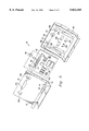
- FIG. 3 is an exploded view showing the components of the docking station of the present invention.
- FIG. 4 is a perspective view of the rear of the docking station of the present invention demonstrating the docking procedure.
- FIG. 1 is a perspective view of a portable PC docking station 10 embodying features of the present invention and showing a portable PC 12 docked therein.
- the PC 12 is of the conventional "clamshell" design and includes a base 14 and a lid 16 rotatably connected to the base 14 via one or more hinges 18 or other known arrangements for enabling the lid 16 to be opened and closed in a conventional manner by rotating the lid 16 relative to the base 14.
- the lid 16 should rotate in excess of 90°.
- the base 14 is generally rectangular having front and rear sides 14a and 14b and a bottom surface 14c.
- the bottom surface 14c is generally planar and adapted to rest the PC 12 on a table top, desk top, or the like.
- the PC 12 contains a conventional pin connector (not shown) for providing an electrical connection to the docking station 10.
- the pin connector is located on the bottom surface 14c as is further described below.
- a display 24, such as a liquid crystal display (“LCD”) is retained within the lid 16 in a conventional manner by a frame or bezel 26 that surrounds the periphery of the display 24.
- the PC 12 is operable in a stand-alone mode through the use of the attached keyboard 20, cursor controller 22 and display 24, or alternatively, the PC 12 can be inserted into and electrically connected, or "docked,” into the docking station 10 of the present invention. Once docked, the PC 12 can be electrically connected to PC networks and peripheral computer equipment, such as a detached keyboard 28 and a detached mouse-like cursor controller 30 via electrical cables 32 as shown in FIG. 1.
- the docking station 10 includes a housing 34 formed by an upper housing portion 36 and a lower housing portion 38 secured together in a conventional method, such as by adhesive, for housing a printed circuit board 40.
- the upper housing portion 36 is generally J-shaped for receiving the PC 12 and includes a generally planar upper surface 42 adapted for engaging the bottom surface 14c of the base 14, a generally planar surface 44 extending perpendicular to the surface 40 and adapted for receiving the front side 14a of the base 14, and a lip section 46, which collectively form a trough 36a.
- the lower housing portion 38 is generally rectangular but (referring to FIG.
- the angle "A" should be predetermined to enable the display 24 to extend generally vertically while in use while the PC 12 is docked in the docking station 12, and is preferably around 60 degrees.
- the board 40 contains a conventional pin connector 50 having connector pins 52 and guide pins 54 that extend through an opening 42a in the surface 42 of the upper housing portion 36 for engaging the pin connector of the PC 12 (not shown) and thereby providing an electrical connection between the PC 12 and the board 40 of the docking station 10. It is understood that the location of the connector 50 and the opening 42a depend upon the location of the pin connector of the PC 12 and have thus been shown in the drawings to be located at only one possible position.
- the board 40 further contains various electronics 56 for enabling the docking station 10 to replicate the ports typically found on desktop PCs that serve to connect the desktop PC to a network and/or peripheral equipment, including conventional I/O connectors (not shown) that extend through openings 38b in the lower housing portion 38.
- An opening 38c is also provided in the lower housing portion 38 for allowing the board 50 to receive electrical power via a power cord 58 (FIG. 4).
- the docking station 10 further includes an ejection mechanism for disengaging the PC 12 from the docking station 10.
- the ejection mechanism includes solenoid-type or similar ejectors 60 housed within the housing 34 and activated by electromagnets 62 located within recesses 38c in the lower housing portion 38. When activated, the ejectors 60 extend through openings 42b in the surface 42 of the upper housing portion 36 and engage the bottom surface 14c of the PC 12 for decoupling the pin connectors of the PC 12 and the docking station 10.
- a switch 64 is provided on the upper housing portion 36 and is electrically connected to the electromagnets 62 for activating the electromagnets 62 and the ejectors 60.
- the power cord 58, the detached keyboard 28, the cursor controller 30 and any other desired network or peripheral computer equipment are connected to the docking station 10 in a conventional manner via the I/O connectors (not shown) extending through the openings 38b and 38c of the lower housing portion 38.
- the docking station 10 is powered through electricity provided by the power cord 58, and once powered, the PC 12 is docked into the docking station 10 by inserting the front side 14a of the base 14 of the PC 12 into the trough 36a formed in the upper housing portion 36.
- the pin connector (not shown) of the PC 12 is connected to the pin connector 50 of the docking station 10 by manually engaging the detents 38a and squeezing the PC 12 down onto the upper housing portion 42 of the docking station as is shown in FIG. 4.
- the PC 12 is turned on in a conventional manner, but is now powered via the docking station 10, thereby recharging (or possibly conserving) the battery power of the PC.
- the lid 16 is opened and positioned to a generally vertical orientation or to any other ergonomically desired position via adjustment of the lid 16 and the orientation of the docking station 10 relative to the user.
- the positions of the detached keyboard 28 and the cursor controller 30 can be ergonomically positioned due to the flexibility of the cables 32.
- activation of the switch 64 energizes the electromagnets 62, thereby activating the ejectors 60 to push against the base 14 of the PC 12 and causing the decoupling of the pin connectors of the PC 12 and the docking station 10.
- Software can be provided within the electronics 56 to ensure that the switch 64 can only activate the ejection mechanism of the docking station 10 once the PC 12 is in a safe condition for undocking, i.e., where no data will be lost.
- the docking station 10 enables the user of the PC 12 to use the display of the docked PC 12, thereby eliminating the need for a separate monitor. This saves the user both expense and extra desk space. Moreover, as the docking station 10 positions the PC 12 at an incline, even more desk space is saved as opposed to having to place the PC 12 flat during operation. Primarily, however, the docking station 10 improves the ergonomics of using a docked PC.
- the user By raising the display of the docked PC, the user is able to orient the display within the desirable 0° (approximately) and 15° (approximately) viewing range (wherein 0° is the vertical orientation), consistent with the normal viewing range of the user without undue movement of the head from a level, resting position.
- This added height together with the ability to move the display relative to the external keyboard 28, allows users to avoid discomfort and prevent repetitive stress related injuries.
- the pin connector 50 of the docking station 10 can be located in various positions, such as in the surface 44 of the upper housing portion 36 that forms the bottom of the trough 36a. Such a location, which assumes that the corresponding PC pin connector is located on the front edge of the PC, would allow the user to dock the PC by pushing it down into the trough 36a.
- the docking station 10 could include a portion opposite the trough 36a along the top of the housing 34 for housing the pin connector 50, which would correspond to current PC pin connector locations.
Abstract
Description
Claims (20)
Priority Applications (1)
| Application Number | Priority Date | Filing Date | Title |
|---|---|---|---|
| US08/763,840 US5822185A (en) | 1996-12-06 | 1996-12-06 | Ergonomic docking station for a portable computer |
Applications Claiming Priority (1)
| Application Number | Priority Date | Filing Date | Title |
|---|---|---|---|
| US08/763,840 US5822185A (en) | 1996-12-06 | 1996-12-06 | Ergonomic docking station for a portable computer |
Publications (1)
| Publication Number | Publication Date |
|---|---|
| US5822185A true US5822185A (en) | 1998-10-13 |
Family
ID=25068955
Family Applications (1)
| Application Number | Title | Priority Date | Filing Date |
|---|---|---|---|
| US08/763,840 Expired - Lifetime US5822185A (en) | 1996-12-06 | 1996-12-06 | Ergonomic docking station for a portable computer |
Country Status (1)
| Country | Link |
|---|---|
| US (1) | US5822185A (en) |
Cited By (47)
| Publication number | Priority date | Publication date | Assignee | Title |
|---|---|---|---|---|
| US6093039A (en) * | 1998-08-06 | 2000-07-25 | Mobility Electronics, Inc. | Docking device for a portable computer |
| US6151218A (en) * | 1998-08-21 | 2000-11-21 | Compaq Computer Corporation | Physical security system for portable computer/port replicator |
| US6208509B1 (en) | 1998-12-02 | 2001-03-27 | Samsung Electronics Co., Ltd. | Portable computer having access door |
| US6239969B1 (en) | 1998-08-03 | 2001-05-29 | Dell Usa, L.P. | Computer docking guidance system |
| NL1015704C2 (en) * | 2000-07-13 | 2002-01-17 | Bakker & Elkhuizen Ergonomie B | A support for a laptop computer has a mount into which the computer is fitted so that a document may be supported over the computer and the display is held at an ergonomically satisfactory position |
| WO2002006937A1 (en) * | 2000-07-13 | 2002-01-24 | Bakker & Elkhuizen Holding B.V. | Support for and method for use of a portable computer |
| US6352233B1 (en) | 1999-11-05 | 2002-03-05 | George Craig Barberich | Portable stand for a laptop computer |
| US6366458B1 (en) * | 1997-06-30 | 2002-04-02 | Sony Corporation | Docking unit for portable electronic device and locking method of docking unit |
| US20020103007A1 (en) * | 2001-01-26 | 2002-08-01 | Jaggers Christopher M. | Portable cell phone docking system |
| US6459589B2 (en) * | 1999-02-12 | 2002-10-01 | Compaq Information Technologies Group Llp | Computer chassis assembly with a single center pluggable midplane board |
| US6480376B1 (en) * | 2000-04-18 | 2002-11-12 | Compaq Computer Corporation | Elevationally adjustable portable computer docking station |
| US6486571B1 (en) * | 2002-03-01 | 2002-11-26 | Ford Global Technologies, Inc. | Power delivery and connection circuit for an automotive vehicle |
| US6501646B2 (en) * | 1998-10-21 | 2002-12-31 | Nec Corporation | Docking apparatus for note-type personal computer having improved releasing function |
| WO2003103357A1 (en) * | 2002-05-28 | 2003-12-11 | Eric Thompson | Vertical docking station |
| US20040017652A1 (en) * | 2001-10-25 | 2004-01-29 | Hewlett-Packard Company | Pedestal computer docking station |
| US20040089783A1 (en) * | 2002-05-22 | 2004-05-13 | Jens Klimke | Keyboard mount |
| US6745986B1 (en) | 2003-01-08 | 2004-06-08 | Gregory David Bright | Support apparatus and method |
| US6807055B2 (en) * | 2000-10-19 | 2004-10-19 | International Business Machines Corporation | Connection enhancement apparatus and information processing apparatus |
| US20040233631A1 (en) * | 2003-05-15 | 2004-11-25 | Charles Lord | Universal portable computer stand and high speed connectivity center |
| US20060023412A1 (en) * | 2003-04-25 | 2006-02-02 | Schedivy George C | Portable video system |
| US20060067044A1 (en) * | 2004-09-29 | 2006-03-30 | Mitsuhiro Yoshida | Supporting apparatus for electronic device |
| US7076270B2 (en) | 2001-02-28 | 2006-07-11 | Dell Products L.P. | Docking station for wireless communication device |
| US20060236086A1 (en) * | 2005-04-18 | 2006-10-19 | Hiroyuki Tsuji | Information processing apparatus and operation control method |
| US20060250767A1 (en) * | 2005-05-04 | 2006-11-09 | Acco Brands Usa Llc | Docking station |
| US20070171239A1 (en) * | 2002-08-08 | 2007-07-26 | Hunt Peter D | Multiple-position docking station for a tablet personal computer |
| US20070228680A1 (en) * | 2006-04-03 | 2007-10-04 | Metro Industries Inc. | Modular Workstation |
| US7327560B1 (en) * | 2005-11-01 | 2008-02-05 | Logitech Europe S.A. | Keyboard with integrated laptop stand |
| US20080059681A1 (en) * | 2006-08-30 | 2008-03-06 | Luca Lodolo | Port replicating apparatus |
| US20080224660A1 (en) * | 2007-03-15 | 2008-09-18 | Mei-Ju Lin | Charging and power-supply device |
| US20090057190A1 (en) * | 2007-08-31 | 2009-03-05 | Idsc Holdings, Llc | Detachable impact protection system for portable data processing system |
| US20090179131A1 (en) * | 2008-01-15 | 2009-07-16 | Charles Lord | Laptop cooling stand with fan |
| US20090213536A1 (en) * | 2008-02-27 | 2009-08-27 | Lewandowski Jason M | Computer docking station for a vehicle |
| WO2009147460A1 (en) * | 2008-06-02 | 2009-12-10 | Brokes Ferenc | Mobile supporting holder for portable computers |
| US20110006724A1 (en) * | 2006-08-21 | 2011-01-13 | Omnicell, Inc. | Solar charged mobile working stations |
| US20110038121A1 (en) * | 2009-06-08 | 2011-02-17 | Logitech Europe S.A. | Comfortable Laptop Computer Stand |
| US20110069445A1 (en) * | 2008-05-19 | 2011-03-24 | Edgar Diego Haren | Notebook Computer Docking Stations |
| USD639814S1 (en) | 2010-06-18 | 2011-06-14 | Xfx Creation, Inc. | Collapsible support device |
| US20120188699A1 (en) * | 2011-01-24 | 2012-07-26 | Hon Hai Precision Industry Co., Ltd. | Notebook computer |
| US8360384B2 (en) | 2009-04-29 | 2013-01-29 | Xfx Creation Inc. | Collapsible support device and composite material for making the same |
| CN102915084A (en) * | 2012-10-09 | 2013-02-06 | 李铁 | Tablet computer convenient to hold |
| CN103235637A (en) * | 2013-04-15 | 2013-08-07 | 李铁 | Intelligent terminal convenient for single-hand holding |
| US20130322002A1 (en) * | 1998-09-18 | 2013-12-05 | Intermetro Industries Corporation | Mobile Computer Workstation |
| US8659889B2 (en) * | 2011-05-20 | 2014-02-25 | Apple Inc. | Docking station for providing digital signage |
| US20140153182A1 (en) * | 2012-12-05 | 2014-06-05 | Belkin International, Inc. | Portable-computer stand and method of providing the same |
| US8773270B2 (en) | 2010-12-06 | 2014-07-08 | Omnicell, Inc. | Computer controlled and monitored medical storage system |
| US8812153B2 (en) | 2006-02-11 | 2014-08-19 | Omnicell, Inc. | Medication dispensing cart |
| US11270792B2 (en) | 2015-10-19 | 2022-03-08 | Icu Medical, Inc. | Hemodynamic monitoring system with detachable display unit |
Citations (14)
| Publication number | Priority date | Publication date | Assignee | Title |
|---|---|---|---|---|
| US5175671A (en) * | 1990-03-20 | 1992-12-29 | Kabushiki Kaisha Toshiba | Expanding apparatus for portable electronic apparatus |
| US5352033A (en) * | 1992-03-27 | 1994-10-04 | Fisher-Rosemount Systems, Inc. | Operator work station having a monitor support assembly |
| US5396400A (en) * | 1993-05-20 | 1995-03-07 | Dell Usa, L.P. | Convertible computer apparatus acting as a desk-top computer or a docking station |
| US5436792A (en) * | 1993-09-10 | 1995-07-25 | Compaq Computer Corporation | Pivotable docking station for use with notepad computer systems |
| US5488572A (en) * | 1994-05-04 | 1996-01-30 | Compaq Computer Corp. | Portable computer system for docking to an expansion base unit |
| US5526493A (en) * | 1993-06-03 | 1996-06-11 | Dell Usa | Docking detection and suspend circuit for portable computer/expansion chassis docking system |
| US5552959A (en) * | 1993-01-05 | 1996-09-03 | Dell Usa, L.P. | Notebook computer docking station having floating connector interface structure |
| US5579528A (en) * | 1991-12-31 | 1996-11-26 | Dell Usa, L.P. | Computer system employing docking bay with spring loaded connector pins and file coherency method |
| US5592362A (en) * | 1993-10-29 | 1997-01-07 | Kabushiki Kaisha Toshiba | Electronic system having portable electronic apparatus and external expansion unit for expanding function of electronic apparatus |
| US5594622A (en) * | 1991-09-06 | 1997-01-14 | Kabushiki Kaisha Toshiba | Electronic apparatus system having an electronic apparatus unit and an expansion unit for expanding the function of the electronic apparatus unit by connection to an expansion card connector |
| US5619397A (en) * | 1994-09-29 | 1997-04-08 | Kabushiki Kaisha Toshiba | Electronic device system including a portable electronic device having a handwriting input device locked to an expansion station when the power switch of the portable electronic device is turned on |
| US5633782A (en) * | 1994-09-09 | 1997-05-27 | International Business Machines Corporation | Docking station for a portable computer with a hindged support frame and movable receptacle assembly |
| US5648762A (en) * | 1994-02-04 | 1997-07-15 | Canon Kabushiki Kaisha | Built-in electronic apparatus and device-detaching method therefor |
| US5687060A (en) * | 1996-06-17 | 1997-11-11 | Compaq Computer Corporation | Vertically oriented docking station apparatus for a portable computer |
-
1996
- 1996-12-06 US US08/763,840 patent/US5822185A/en not_active Expired - Lifetime
Patent Citations (14)
| Publication number | Priority date | Publication date | Assignee | Title |
|---|---|---|---|---|
| US5175671A (en) * | 1990-03-20 | 1992-12-29 | Kabushiki Kaisha Toshiba | Expanding apparatus for portable electronic apparatus |
| US5594622A (en) * | 1991-09-06 | 1997-01-14 | Kabushiki Kaisha Toshiba | Electronic apparatus system having an electronic apparatus unit and an expansion unit for expanding the function of the electronic apparatus unit by connection to an expansion card connector |
| US5579528A (en) * | 1991-12-31 | 1996-11-26 | Dell Usa, L.P. | Computer system employing docking bay with spring loaded connector pins and file coherency method |
| US5352033A (en) * | 1992-03-27 | 1994-10-04 | Fisher-Rosemount Systems, Inc. | Operator work station having a monitor support assembly |
| US5552959A (en) * | 1993-01-05 | 1996-09-03 | Dell Usa, L.P. | Notebook computer docking station having floating connector interface structure |
| US5396400A (en) * | 1993-05-20 | 1995-03-07 | Dell Usa, L.P. | Convertible computer apparatus acting as a desk-top computer or a docking station |
| US5526493A (en) * | 1993-06-03 | 1996-06-11 | Dell Usa | Docking detection and suspend circuit for portable computer/expansion chassis docking system |
| US5436792A (en) * | 1993-09-10 | 1995-07-25 | Compaq Computer Corporation | Pivotable docking station for use with notepad computer systems |
| US5592362A (en) * | 1993-10-29 | 1997-01-07 | Kabushiki Kaisha Toshiba | Electronic system having portable electronic apparatus and external expansion unit for expanding function of electronic apparatus |
| US5648762A (en) * | 1994-02-04 | 1997-07-15 | Canon Kabushiki Kaisha | Built-in electronic apparatus and device-detaching method therefor |
| US5488572A (en) * | 1994-05-04 | 1996-01-30 | Compaq Computer Corp. | Portable computer system for docking to an expansion base unit |
| US5633782A (en) * | 1994-09-09 | 1997-05-27 | International Business Machines Corporation | Docking station for a portable computer with a hindged support frame and movable receptacle assembly |
| US5619397A (en) * | 1994-09-29 | 1997-04-08 | Kabushiki Kaisha Toshiba | Electronic device system including a portable electronic device having a handwriting input device locked to an expansion station when the power switch of the portable electronic device is turned on |
| US5687060A (en) * | 1996-06-17 | 1997-11-11 | Compaq Computer Corporation | Vertically oriented docking station apparatus for a portable computer |
Cited By (73)
| Publication number | Priority date | Publication date | Assignee | Title |
|---|---|---|---|---|
| US6366458B1 (en) * | 1997-06-30 | 2002-04-02 | Sony Corporation | Docking unit for portable electronic device and locking method of docking unit |
| US6239969B1 (en) | 1998-08-03 | 2001-05-29 | Dell Usa, L.P. | Computer docking guidance system |
| US6093039A (en) * | 1998-08-06 | 2000-07-25 | Mobility Electronics, Inc. | Docking device for a portable computer |
| US6151218A (en) * | 1998-08-21 | 2000-11-21 | Compaq Computer Corporation | Physical security system for portable computer/port replicator |
| US20130322002A1 (en) * | 1998-09-18 | 2013-12-05 | Intermetro Industries Corporation | Mobile Computer Workstation |
| US9389643B1 (en) | 1998-09-18 | 2016-07-12 | Intermetro Industries Corporation | Mobile computer workstation |
| US6501646B2 (en) * | 1998-10-21 | 2002-12-31 | Nec Corporation | Docking apparatus for note-type personal computer having improved releasing function |
| US6208509B1 (en) | 1998-12-02 | 2001-03-27 | Samsung Electronics Co., Ltd. | Portable computer having access door |
| US6459589B2 (en) * | 1999-02-12 | 2002-10-01 | Compaq Information Technologies Group Llp | Computer chassis assembly with a single center pluggable midplane board |
| US6352233B1 (en) | 1999-11-05 | 2002-03-05 | George Craig Barberich | Portable stand for a laptop computer |
| US6480376B1 (en) * | 2000-04-18 | 2002-11-12 | Compaq Computer Corporation | Elevationally adjustable portable computer docking station |
| US6583985B2 (en) | 2000-04-18 | 2003-06-24 | Hewlett-Packard Development Company | Elevationally adjustable portable computer docking station |
| WO2002006937A1 (en) * | 2000-07-13 | 2002-01-24 | Bakker & Elkhuizen Holding B.V. | Support for and method for use of a portable computer |
| NL1015704C2 (en) * | 2000-07-13 | 2002-01-17 | Bakker & Elkhuizen Ergonomie B | A support for a laptop computer has a mount into which the computer is fitted so that a document may be supported over the computer and the display is held at an ergonomically satisfactory position |
| AU2001277810B2 (en) * | 2000-07-13 | 2004-07-29 | Oahwip B.V. | Support for and method for use of a portable computer |
| US6913238B2 (en) | 2000-07-13 | 2005-07-05 | Bakker & Elkhuizen B.V. | Support for and method for use of a portable computer |
| EP1447024A3 (en) * | 2000-07-13 | 2004-12-15 | Bakker & Elkhuizen Holding B.V. | Support for and method for use of a portable computer |
| US6807055B2 (en) * | 2000-10-19 | 2004-10-19 | International Business Machines Corporation | Connection enhancement apparatus and information processing apparatus |
| US20020103007A1 (en) * | 2001-01-26 | 2002-08-01 | Jaggers Christopher M. | Portable cell phone docking system |
| US7013163B2 (en) | 2001-01-26 | 2006-03-14 | Dell Products L.P. | Portable wireless communication device docking system |
| US7076270B2 (en) | 2001-02-28 | 2006-07-11 | Dell Products L.P. | Docking station for wireless communication device |
| US20040017652A1 (en) * | 2001-10-25 | 2004-01-29 | Hewlett-Packard Company | Pedestal computer docking station |
| US6963487B2 (en) | 2001-10-25 | 2005-11-08 | Hewlett-Packard Development Company, L.P. | Pedestal computer docking station |
| US6486571B1 (en) * | 2002-03-01 | 2002-11-26 | Ford Global Technologies, Inc. | Power delivery and connection circuit for an automotive vehicle |
| US20040089783A1 (en) * | 2002-05-22 | 2004-05-13 | Jens Klimke | Keyboard mount |
| WO2003103357A1 (en) * | 2002-05-28 | 2003-12-11 | Eric Thompson | Vertical docking station |
| US20050162824A1 (en) * | 2002-05-28 | 2005-07-28 | Eric Thompson | Vertical docking station |
| US7679902B2 (en) * | 2002-05-28 | 2010-03-16 | Eric Thompson | Vertical docking station |
| US20070171239A1 (en) * | 2002-08-08 | 2007-07-26 | Hunt Peter D | Multiple-position docking station for a tablet personal computer |
| US6745986B1 (en) | 2003-01-08 | 2004-06-08 | Gregory David Bright | Support apparatus and method |
| US7440275B2 (en) * | 2003-04-25 | 2008-10-21 | Audiovox Corporation | Portable video system including a base unit secured to a substrate for selectively coupling a video unit |
| US20060023412A1 (en) * | 2003-04-25 | 2006-02-02 | Schedivy George C | Portable video system |
| US20040233631A1 (en) * | 2003-05-15 | 2004-11-25 | Charles Lord | Universal portable computer stand and high speed connectivity center |
| US7035100B2 (en) | 2003-05-15 | 2006-04-25 | Hotwire Development Llc | Universal portable computer stand and high speed connectivity center |
| WO2004104803A3 (en) * | 2003-05-15 | 2005-03-17 | Hotwire Dev Llc | Universal portable computer stand and high speed connectivity center |
| WO2004104803A2 (en) * | 2003-05-15 | 2004-12-02 | Hotwire Development, Llc | Universal portable computer stand and high speed connectivity center |
| US20060067044A1 (en) * | 2004-09-29 | 2006-03-30 | Mitsuhiro Yoshida | Supporting apparatus for electronic device |
| US20060236086A1 (en) * | 2005-04-18 | 2006-10-19 | Hiroyuki Tsuji | Information processing apparatus and operation control method |
| US20060250767A1 (en) * | 2005-05-04 | 2006-11-09 | Acco Brands Usa Llc | Docking station |
| US7327560B1 (en) * | 2005-11-01 | 2008-02-05 | Logitech Europe S.A. | Keyboard with integrated laptop stand |
| US9801791B2 (en) | 2006-02-11 | 2017-10-31 | Mv Circuit Design Inc. | Medication dispensing cart |
| US8812153B2 (en) | 2006-02-11 | 2014-08-19 | Omnicell, Inc. | Medication dispensing cart |
| US20070228680A1 (en) * | 2006-04-03 | 2007-10-04 | Metro Industries Inc. | Modular Workstation |
| US9587878B2 (en) | 2006-08-21 | 2017-03-07 | Omnicell, Inc. | Medication dispensing cart |
| US20110006724A1 (en) * | 2006-08-21 | 2011-01-13 | Omnicell, Inc. | Solar charged mobile working stations |
| US8378620B2 (en) | 2006-08-21 | 2013-02-19 | Omnicell, Inc. | Solar charged mobile working stations |
| US20080059681A1 (en) * | 2006-08-30 | 2008-03-06 | Luca Lodolo | Port replicating apparatus |
| US7558898B2 (en) | 2006-08-30 | 2009-07-07 | ACCO Brands Corporation | Port replicating apparatus |
| US20080224660A1 (en) * | 2007-03-15 | 2008-09-18 | Mei-Ju Lin | Charging and power-supply device |
| US7675264B2 (en) * | 2007-03-15 | 2010-03-09 | Powertech Industrial Co., Ltd. | Charging and power-supply device |
| US20090057190A1 (en) * | 2007-08-31 | 2009-03-05 | Idsc Holdings, Llc | Detachable impact protection system for portable data processing system |
| US20090179131A1 (en) * | 2008-01-15 | 2009-07-16 | Charles Lord | Laptop cooling stand with fan |
| USRE43869E1 (en) | 2008-02-27 | 2012-12-25 | L&P Property Management Company | Computer docking station for a vehicle |
| US20110128689A1 (en) * | 2008-02-27 | 2011-06-02 | Lewandowski Jason M | Computer docking station for a vehicle |
| US8098488B2 (en) | 2008-02-27 | 2012-01-17 | L&P Property Management Company | Computer docking station for a vehicle |
| US7978466B2 (en) | 2008-02-27 | 2011-07-12 | L&P Property Management Company | Computer docking station for a vehicle |
| US20090213536A1 (en) * | 2008-02-27 | 2009-08-27 | Lewandowski Jason M | Computer docking station for a vehicle |
| US8634188B2 (en) * | 2008-05-19 | 2014-01-21 | Hewlett-Packard Development Company, L.P. | Notebook computer docking stations |
| US20110069445A1 (en) * | 2008-05-19 | 2011-03-24 | Edgar Diego Haren | Notebook Computer Docking Stations |
| WO2009147460A1 (en) * | 2008-06-02 | 2009-12-10 | Brokes Ferenc | Mobile supporting holder for portable computers |
| US8360384B2 (en) | 2009-04-29 | 2013-01-29 | Xfx Creation Inc. | Collapsible support device and composite material for making the same |
| US8537537B2 (en) | 2009-06-08 | 2013-09-17 | Logitech Europe S.A. | Comfortable laptop computer stand |
| US20110038121A1 (en) * | 2009-06-08 | 2011-02-17 | Logitech Europe S.A. | Comfortable Laptop Computer Stand |
| USD639814S1 (en) | 2010-06-18 | 2011-06-14 | Xfx Creation, Inc. | Collapsible support device |
| US9976801B2 (en) | 2010-12-06 | 2018-05-22 | Omnicell, Inc. | Computer controlled and monitored medical storage system |
| US8773270B2 (en) | 2010-12-06 | 2014-07-08 | Omnicell, Inc. | Computer controlled and monitored medical storage system |
| US9523534B2 (en) | 2010-12-06 | 2016-12-20 | Omnicell, Inc. | Computer controlled and monitored medical storage system |
| US20120188699A1 (en) * | 2011-01-24 | 2012-07-26 | Hon Hai Precision Industry Co., Ltd. | Notebook computer |
| US8659889B2 (en) * | 2011-05-20 | 2014-02-25 | Apple Inc. | Docking station for providing digital signage |
| CN102915084A (en) * | 2012-10-09 | 2013-02-06 | 李铁 | Tablet computer convenient to hold |
| US20140153182A1 (en) * | 2012-12-05 | 2014-06-05 | Belkin International, Inc. | Portable-computer stand and method of providing the same |
| CN103235637A (en) * | 2013-04-15 | 2013-08-07 | 李铁 | Intelligent terminal convenient for single-hand holding |
| US11270792B2 (en) | 2015-10-19 | 2022-03-08 | Icu Medical, Inc. | Hemodynamic monitoring system with detachable display unit |
Similar Documents
| Publication | Publication Date | Title |
|---|---|---|
| US5822185A (en) | Ergonomic docking station for a portable computer | |
| KR100488012B1 (en) | Portable computer system | |
| US6208508B1 (en) | Space-saving docking station for vertically supporting an opened notebook computer | |
| EP0834793B1 (en) | Computer docking station for horizontal or vertical positioning | |
| US7091961B2 (en) | Desktop device with adjustable flat screen display | |
| US7149080B2 (en) | Flat panel computer having an integrally housed flat panel display | |
| US6788532B2 (en) | Portable computer of multifunction type | |
| US8896580B2 (en) | Instrument-activated sub-surface computer buttons and system and method incorporating same | |
| US7542052B2 (en) | System and method of switching viewing orientations of a display | |
| US6930881B2 (en) | Portable computer having a split screen and a multi-purpose hinge | |
| US6583985B2 (en) | Elevationally adjustable portable computer docking station | |
| KR100491933B1 (en) | Detachable flat panel computer display and support | |
| US7679902B2 (en) | Vertical docking station | |
| US6188572B1 (en) | Movable docking station electrical connector | |
| US5815735A (en) | Portable computer with removable display screen using removably mateable connectors to form the sole supporting interconnection between the computer base portion and display screen structure | |
| US5875094A (en) | Portable computer docking station with adjustable insertion angle | |
| WO2002082213A2 (en) | Portable computer | |
| US20020085343A1 (en) | Modular portable computer with detachable main board module | |
| US5894406A (en) | Elevated separate external keyboard apparatus for use with portable computer | |
| US6023411A (en) | Modular docking tray and method | |
| US20050270731A1 (en) | Computer docking system | |
| US6392880B1 (en) | Portable computer with removable bottom component housing | |
| US8238092B2 (en) | Connecting module and electronic device coupling system | |
| US6573843B1 (en) | Snap-on keyboard and method of integrating keyboard |
Legal Events
| Date | Code | Title | Description |
|---|---|---|---|
| AS | Assignment |
Owner name: DELL COMPUTER CORPORATION, TEXAS Free format text: ASSIGNMENT OF ASSIGNORS INTEREST;ASSIGNOR:CAVELLO, CHRISTOPHER;REEL/FRAME:008353/0834 Effective date: 19961205 |
|
| STCF | Information on status: patent grant |
Free format text: PATENTED CASE |
|
| FPAY | Fee payment |
Year of fee payment: 4 |
|
| REMI | Maintenance fee reminder mailed | ||
| FEPP | Fee payment procedure |
Free format text: PAYOR NUMBER ASSIGNED (ORIGINAL EVENT CODE: ASPN); ENTITY STATUS OF PATENT OWNER: LARGE ENTITY |
|
| FPAY | Fee payment |
Year of fee payment: 8 |
|
| FPAY | Fee payment |
Year of fee payment: 12 |
|
| AS | Assignment |
Owner name: DELL INC., TEXAS Free format text: CHANGE OF NAME;ASSIGNOR:DELL COMPUTER CORPORATION;REEL/FRAME:031647/0074 Effective date: 20030718 |
|
| AS | Assignment |
Owner name: BANK OF NEW YORK MELLON TRUST COMPANY, N.A., AS FI Free format text: PATENT SECURITY AGREEMENT (NOTES);ASSIGNORS:APPASSURE SOFTWARE, INC.;ASAP SOFTWARE EXPRESS, INC.;BOOMI, INC.;AND OTHERS;REEL/FRAME:031897/0348 Effective date: 20131029 Owner name: BANK OF AMERICA, N.A., AS ADMINISTRATIVE AGENT, TE Free format text: PATENT SECURITY AGREEMENT (ABL);ASSIGNORS:DELL INC.;APPASSURE SOFTWARE, INC.;ASAP SOFTWARE EXPRESS, INC.;AND OTHERS;REEL/FRAME:031898/0001 Effective date: 20131029 Owner name: BANK OF NEW YORK MELLON TRUST COMPANY, N.A., AS FIRST LIEN COLLATERAL AGENT, TEXAS Free format text: PATENT SECURITY AGREEMENT (NOTES);ASSIGNORS:APPASSURE SOFTWARE, INC.;ASAP SOFTWARE EXPRESS, INC.;BOOMI, INC.;AND OTHERS;REEL/FRAME:031897/0348 Effective date: 20131029 Owner name: BANK OF AMERICA, N.A., AS COLLATERAL AGENT, NORTH CAROLINA Free format text: PATENT SECURITY AGREEMENT (TERM LOAN);ASSIGNORS:DELL INC.;APPASSURE SOFTWARE, INC.;ASAP SOFTWARE EXPRESS, INC.;AND OTHERS;REEL/FRAME:031899/0261 Effective date: 20131029 Owner name: BANK OF AMERICA, N.A., AS ADMINISTRATIVE AGENT, TEXAS Free format text: PATENT SECURITY AGREEMENT (ABL);ASSIGNORS:DELL INC.;APPASSURE SOFTWARE, INC.;ASAP SOFTWARE EXPRESS, INC.;AND OTHERS;REEL/FRAME:031898/0001 Effective date: 20131029 Owner name: BANK OF AMERICA, N.A., AS COLLATERAL AGENT, NORTH Free format text: PATENT SECURITY AGREEMENT (TERM LOAN);ASSIGNORS:DELL INC.;APPASSURE SOFTWARE, INC.;ASAP SOFTWARE EXPRESS, INC.;AND OTHERS;REEL/FRAME:031899/0261 Effective date: 20131029 |
|
| AS | Assignment |
Owner name: DELL PRODUCTS L.P., TEXAS Free format text: ASSIGNMENT OF ASSIGNORS INTEREST;ASSIGNOR:DELL INC.;REEL/FRAME:038222/0748 Effective date: 20160407 |
|
| AS | Assignment |
Owner name: COMPELLANT TECHNOLOGIES, INC., MINNESOTA Free format text: RELEASE BY SECURED PARTY;ASSIGNOR:BANK OF AMERICA, N.A., AS ADMINISTRATIVE AGENT;REEL/FRAME:040065/0216 Effective date: 20160907 Owner name: DELL MARKETING L.P., TEXAS Free format text: RELEASE BY SECURED PARTY;ASSIGNOR:BANK OF AMERICA, N.A., AS ADMINISTRATIVE AGENT;REEL/FRAME:040065/0216 Effective date: 20160907 Owner name: SECUREWORKS, INC., GEORGIA Free format text: RELEASE BY SECURED PARTY;ASSIGNOR:BANK OF AMERICA, N.A., AS ADMINISTRATIVE AGENT;REEL/FRAME:040065/0216 Effective date: 20160907 Owner name: DELL INC., TEXAS Free format text: RELEASE BY SECURED PARTY;ASSIGNOR:BANK OF AMERICA, N.A., AS ADMINISTRATIVE AGENT;REEL/FRAME:040065/0216 Effective date: 20160907 Owner name: DELL SOFTWARE INC., CALIFORNIA Free format text: RELEASE BY SECURED PARTY;ASSIGNOR:BANK OF AMERICA, N.A., AS ADMINISTRATIVE AGENT;REEL/FRAME:040065/0216 Effective date: 20160907 Owner name: DELL PRODUCTS L.P., TEXAS Free format text: RELEASE BY SECURED PARTY;ASSIGNOR:BANK OF AMERICA, N.A., AS ADMINISTRATIVE AGENT;REEL/FRAME:040065/0216 Effective date: 20160907 Owner name: WYSE TECHNOLOGY L.L.C., CALIFORNIA Free format text: RELEASE BY SECURED PARTY;ASSIGNOR:BANK OF AMERICA, N.A., AS ADMINISTRATIVE AGENT;REEL/FRAME:040065/0216 Effective date: 20160907 Owner name: DELL USA L.P., TEXAS Free format text: RELEASE BY SECURED PARTY;ASSIGNOR:BANK OF AMERICA, N.A., AS ADMINISTRATIVE AGENT;REEL/FRAME:040065/0216 Effective date: 20160907 Owner name: APPASSURE SOFTWARE, INC., VIRGINIA Free format text: RELEASE BY SECURED PARTY;ASSIGNOR:BANK OF AMERICA, N.A., AS ADMINISTRATIVE AGENT;REEL/FRAME:040065/0216 Effective date: 20160907 Owner name: ASAP SOFTWARE EXPRESS, INC., ILLINOIS Free format text: RELEASE BY SECURED PARTY;ASSIGNOR:BANK OF AMERICA, N.A., AS ADMINISTRATIVE AGENT;REEL/FRAME:040065/0216 Effective date: 20160907 Owner name: PEROT SYSTEMS CORPORATION, TEXAS Free format text: RELEASE BY SECURED PARTY;ASSIGNOR:BANK OF AMERICA, N.A., AS ADMINISTRATIVE AGENT;REEL/FRAME:040065/0216 Effective date: 20160907 Owner name: CREDANT TECHNOLOGIES, INC., TEXAS Free format text: RELEASE BY SECURED PARTY;ASSIGNOR:BANK OF AMERICA, N.A., AS ADMINISTRATIVE AGENT;REEL/FRAME:040065/0216 Effective date: 20160907 Owner name: FORCE10 NETWORKS, INC., CALIFORNIA Free format text: RELEASE BY SECURED PARTY;ASSIGNOR:BANK OF AMERICA, N.A., AS ADMINISTRATIVE AGENT;REEL/FRAME:040065/0216 Effective date: 20160907 |
|
| AS | Assignment |
Owner name: DELL PRODUCTS L.P., TEXAS Free format text: RELEASE BY SECURED PARTY;ASSIGNOR:BANK OF AMERICA, N.A., AS COLLATERAL AGENT;REEL/FRAME:040040/0001 Effective date: 20160907 Owner name: CREDANT TECHNOLOGIES, INC., TEXAS Free format text: RELEASE BY SECURED PARTY;ASSIGNOR:BANK OF AMERICA, N.A., AS COLLATERAL AGENT;REEL/FRAME:040040/0001 Effective date: 20160907 Owner name: DELL INC., TEXAS Free format text: RELEASE BY SECURED PARTY;ASSIGNOR:BANK OF AMERICA, N.A., AS COLLATERAL AGENT;REEL/FRAME:040040/0001 Effective date: 20160907 Owner name: COMPELLENT TECHNOLOGIES, INC., MINNESOTA Free format text: RELEASE BY SECURED PARTY;ASSIGNOR:BANK OF AMERICA, N.A., AS COLLATERAL AGENT;REEL/FRAME:040040/0001 Effective date: 20160907 Owner name: SECUREWORKS, INC., GEORGIA Free format text: RELEASE BY SECURED PARTY;ASSIGNOR:BANK OF AMERICA, N.A., AS COLLATERAL AGENT;REEL/FRAME:040040/0001 Effective date: 20160907 Owner name: FORCE10 NETWORKS, INC., CALIFORNIA Free format text: RELEASE BY SECURED PARTY;ASSIGNOR:BANK OF AMERICA, N.A., AS COLLATERAL AGENT;REEL/FRAME:040040/0001 Effective date: 20160907 Owner name: PEROT SYSTEMS CORPORATION, TEXAS Free format text: RELEASE BY SECURED PARTY;ASSIGNOR:BANK OF AMERICA, N.A., AS COLLATERAL AGENT;REEL/FRAME:040040/0001 Effective date: 20160907 Owner name: DELL SOFTWARE INC., CALIFORNIA Free format text: RELEASE BY SECURED PARTY;ASSIGNOR:BANK OF AMERICA, N.A., AS COLLATERAL AGENT;REEL/FRAME:040040/0001 Effective date: 20160907 Owner name: DELL USA L.P., TEXAS Free format text: RELEASE BY SECURED PARTY;ASSIGNOR:BANK OF AMERICA, N.A., AS COLLATERAL AGENT;REEL/FRAME:040040/0001 Effective date: 20160907 Owner name: WYSE TECHNOLOGY L.L.C., CALIFORNIA Free format text: RELEASE BY SECURED PARTY;ASSIGNOR:BANK OF AMERICA, N.A., AS COLLATERAL AGENT;REEL/FRAME:040040/0001 Effective date: 20160907 Owner name: APPASSURE SOFTWARE, INC., VIRGINIA Free format text: RELEASE BY SECURED PARTY;ASSIGNOR:BANK OF AMERICA, N.A., AS COLLATERAL AGENT;REEL/FRAME:040040/0001 Effective date: 20160907 Owner name: DELL MARKETING L.P., TEXAS Free format text: RELEASE BY SECURED PARTY;ASSIGNOR:BANK OF AMERICA, N.A., AS COLLATERAL AGENT;REEL/FRAME:040040/0001 Effective date: 20160907 Owner name: ASAP SOFTWARE EXPRESS, INC., ILLINOIS Free format text: RELEASE BY SECURED PARTY;ASSIGNOR:BANK OF AMERICA, N.A., AS COLLATERAL AGENT;REEL/FRAME:040040/0001 Effective date: 20160907 Owner name: DELL PRODUCTS L.P., TEXAS Free format text: RELEASE BY SECURED PARTY;ASSIGNOR:BANK OF NEW YORK MELLON TRUST COMPANY, N.A., AS COLLATERAL AGENT;REEL/FRAME:040065/0618 Effective date: 20160907 Owner name: FORCE10 NETWORKS, INC., CALIFORNIA Free format text: RELEASE BY SECURED PARTY;ASSIGNOR:BANK OF NEW YORK MELLON TRUST COMPANY, N.A., AS COLLATERAL AGENT;REEL/FRAME:040065/0618 Effective date: 20160907 Owner name: DELL SOFTWARE INC., CALIFORNIA Free format text: RELEASE BY SECURED PARTY;ASSIGNOR:BANK OF NEW YORK MELLON TRUST COMPANY, N.A., AS COLLATERAL AGENT;REEL/FRAME:040065/0618 Effective date: 20160907 Owner name: APPASSURE SOFTWARE, INC., VIRGINIA Free format text: RELEASE BY SECURED PARTY;ASSIGNOR:BANK OF NEW YORK MELLON TRUST COMPANY, N.A., AS COLLATERAL AGENT;REEL/FRAME:040065/0618 Effective date: 20160907 Owner name: COMPELLENT TECHNOLOGIES, INC., MINNESOTA Free format text: RELEASE BY SECURED PARTY;ASSIGNOR:BANK OF NEW YORK MELLON TRUST COMPANY, N.A., AS COLLATERAL AGENT;REEL/FRAME:040065/0618 Effective date: 20160907 Owner name: ASAP SOFTWARE EXPRESS, INC., ILLINOIS Free format text: RELEASE BY SECURED PARTY;ASSIGNOR:BANK OF NEW YORK MELLON TRUST COMPANY, N.A., AS COLLATERAL AGENT;REEL/FRAME:040065/0618 Effective date: 20160907 Owner name: CREDANT TECHNOLOGIES, INC., TEXAS Free format text: RELEASE BY SECURED PARTY;ASSIGNOR:BANK OF NEW YORK MELLON TRUST COMPANY, N.A., AS COLLATERAL AGENT;REEL/FRAME:040065/0618 Effective date: 20160907 Owner name: DELL INC., TEXAS Free format text: RELEASE BY SECURED PARTY;ASSIGNOR:BANK OF NEW YORK MELLON TRUST COMPANY, N.A., AS COLLATERAL AGENT;REEL/FRAME:040065/0618 Effective date: 20160907 Owner name: WYSE TECHNOLOGY L.L.C., CALIFORNIA Free format text: RELEASE BY SECURED PARTY;ASSIGNOR:BANK OF NEW YORK MELLON TRUST COMPANY, N.A., AS COLLATERAL AGENT;REEL/FRAME:040065/0618 Effective date: 20160907 Owner name: PEROT SYSTEMS CORPORATION, TEXAS Free format text: RELEASE BY SECURED PARTY;ASSIGNOR:BANK OF NEW YORK MELLON TRUST COMPANY, N.A., AS COLLATERAL AGENT;REEL/FRAME:040065/0618 Effective date: 20160907 Owner name: DELL USA L.P., TEXAS Free format text: RELEASE BY SECURED PARTY;ASSIGNOR:BANK OF NEW YORK MELLON TRUST COMPANY, N.A., AS COLLATERAL AGENT;REEL/FRAME:040065/0618 Effective date: 20160907 Owner name: DELL MARKETING L.P., TEXAS Free format text: RELEASE BY SECURED PARTY;ASSIGNOR:BANK OF NEW YORK MELLON TRUST COMPANY, N.A., AS COLLATERAL AGENT;REEL/FRAME:040065/0618 Effective date: 20160907 Owner name: SECUREWORKS, INC., GEORGIA Free format text: RELEASE BY SECURED PARTY;ASSIGNOR:BANK OF NEW YORK MELLON TRUST COMPANY, N.A., AS COLLATERAL AGENT;REEL/FRAME:040065/0618 Effective date: 20160907 |
|
| AS | Assignment |
Owner name: CREDIT SUISSE AG, CAYMAN ISLANDS BRANCH, AS COLLATERAL AGENT, NORTH CAROLINA Free format text: SECURITY AGREEMENT;ASSIGNORS:ASAP SOFTWARE EXPRESS, INC.;AVENTAIL LLC;CREDANT TECHNOLOGIES, INC.;AND OTHERS;REEL/FRAME:040134/0001 Effective date: 20160907 Owner name: THE BANK OF NEW YORK MELLON TRUST COMPANY, N.A., AS NOTES COLLATERAL AGENT, TEXAS Free format text: SECURITY AGREEMENT;ASSIGNORS:ASAP SOFTWARE EXPRESS, INC.;AVENTAIL LLC;CREDANT TECHNOLOGIES, INC.;AND OTHERS;REEL/FRAME:040136/0001 Effective date: 20160907 Owner name: CREDIT SUISSE AG, CAYMAN ISLANDS BRANCH, AS COLLAT Free format text: SECURITY AGREEMENT;ASSIGNORS:ASAP SOFTWARE EXPRESS, INC.;AVENTAIL LLC;CREDANT TECHNOLOGIES, INC.;AND OTHERS;REEL/FRAME:040134/0001 Effective date: 20160907 Owner name: THE BANK OF NEW YORK MELLON TRUST COMPANY, N.A., A Free format text: SECURITY AGREEMENT;ASSIGNORS:ASAP SOFTWARE EXPRESS, INC.;AVENTAIL LLC;CREDANT TECHNOLOGIES, INC.;AND OTHERS;REEL/FRAME:040136/0001 Effective date: 20160907 |
|
| AS | Assignment |
Owner name: WYSE TECHNOLOGY L.L.C., CALIFORNIA Free format text: RELEASE BY SECURED PARTY;ASSIGNOR:CREDIT SUISSE AG, CAYMAN ISLANDS BRANCH;REEL/FRAME:058216/0001 Effective date: 20211101 Owner name: SCALEIO LLC, MASSACHUSETTS Free format text: RELEASE BY SECURED PARTY;ASSIGNOR:CREDIT SUISSE AG, CAYMAN ISLANDS BRANCH;REEL/FRAME:058216/0001 Effective date: 20211101 Owner name: MOZY, INC., WASHINGTON Free format text: RELEASE BY SECURED PARTY;ASSIGNOR:CREDIT SUISSE AG, CAYMAN ISLANDS BRANCH;REEL/FRAME:058216/0001 Effective date: 20211101 Owner name: MAGINATICS LLC, CALIFORNIA Free format text: RELEASE BY SECURED PARTY;ASSIGNOR:CREDIT SUISSE AG, CAYMAN ISLANDS BRANCH;REEL/FRAME:058216/0001 Effective date: 20211101 Owner name: FORCE10 NETWORKS, INC., CALIFORNIA Free format text: RELEASE BY SECURED PARTY;ASSIGNOR:CREDIT SUISSE AG, CAYMAN ISLANDS BRANCH;REEL/FRAME:058216/0001 Effective date: 20211101 Owner name: EMC IP HOLDING COMPANY LLC, TEXAS Free format text: RELEASE BY SECURED PARTY;ASSIGNOR:CREDIT SUISSE AG, CAYMAN ISLANDS BRANCH;REEL/FRAME:058216/0001 Effective date: 20211101 Owner name: EMC CORPORATION, MASSACHUSETTS Free format text: RELEASE BY SECURED PARTY;ASSIGNOR:CREDIT SUISSE AG, CAYMAN ISLANDS BRANCH;REEL/FRAME:058216/0001 Effective date: 20211101 Owner name: DELL SYSTEMS CORPORATION, TEXAS Free format text: RELEASE BY SECURED PARTY;ASSIGNOR:CREDIT SUISSE AG, CAYMAN ISLANDS BRANCH;REEL/FRAME:058216/0001 Effective date: 20211101 Owner name: DELL SOFTWARE INC., CALIFORNIA Free format text: RELEASE BY SECURED PARTY;ASSIGNOR:CREDIT SUISSE AG, CAYMAN ISLANDS BRANCH;REEL/FRAME:058216/0001 Effective date: 20211101 Owner name: DELL PRODUCTS L.P., TEXAS Free format text: RELEASE BY SECURED PARTY;ASSIGNOR:CREDIT SUISSE AG, CAYMAN ISLANDS BRANCH;REEL/FRAME:058216/0001 Effective date: 20211101 Owner name: DELL MARKETING L.P., TEXAS Free format text: RELEASE BY SECURED PARTY;ASSIGNOR:CREDIT SUISSE AG, CAYMAN ISLANDS BRANCH;REEL/FRAME:058216/0001 Effective date: 20211101 Owner name: DELL INTERNATIONAL, L.L.C., TEXAS Free format text: RELEASE BY SECURED PARTY;ASSIGNOR:CREDIT SUISSE AG, CAYMAN ISLANDS BRANCH;REEL/FRAME:058216/0001 Effective date: 20211101 Owner name: DELL USA L.P., TEXAS Free format text: RELEASE BY SECURED PARTY;ASSIGNOR:CREDIT SUISSE AG, CAYMAN ISLANDS BRANCH;REEL/FRAME:058216/0001 Effective date: 20211101 Owner name: CREDANT TECHNOLOGIES, INC., TEXAS Free format text: RELEASE BY SECURED PARTY;ASSIGNOR:CREDIT SUISSE AG, CAYMAN ISLANDS BRANCH;REEL/FRAME:058216/0001 Effective date: 20211101 Owner name: AVENTAIL LLC, CALIFORNIA Free format text: RELEASE BY SECURED PARTY;ASSIGNOR:CREDIT SUISSE AG, CAYMAN ISLANDS BRANCH;REEL/FRAME:058216/0001 Effective date: 20211101 Owner name: ASAP SOFTWARE EXPRESS, INC., ILLINOIS Free format text: RELEASE BY SECURED PARTY;ASSIGNOR:CREDIT SUISSE AG, CAYMAN ISLANDS BRANCH;REEL/FRAME:058216/0001 Effective date: 20211101 |
|
| AS | Assignment |
Owner name: SCALEIO LLC, MASSACHUSETTS Free format text: RELEASE OF SECURITY INTEREST IN PATENTS PREVIOUSLY RECORDED AT REEL/FRAME (040136/0001);ASSIGNOR:THE BANK OF NEW YORK MELLON TRUST COMPANY, N.A., AS NOTES COLLATERAL AGENT;REEL/FRAME:061324/0001 Effective date: 20220329 Owner name: EMC IP HOLDING COMPANY LLC (ON BEHALF OF ITSELF AND AS SUCCESSOR-IN-INTEREST TO MOZY, INC.), TEXAS Free format text: RELEASE OF SECURITY INTEREST IN PATENTS PREVIOUSLY RECORDED AT REEL/FRAME (040136/0001);ASSIGNOR:THE BANK OF NEW YORK MELLON TRUST COMPANY, N.A., AS NOTES COLLATERAL AGENT;REEL/FRAME:061324/0001 Effective date: 20220329 Owner name: EMC CORPORATION (ON BEHALF OF ITSELF AND AS SUCCESSOR-IN-INTEREST TO MAGINATICS LLC), MASSACHUSETTS Free format text: RELEASE OF SECURITY INTEREST IN PATENTS PREVIOUSLY RECORDED AT REEL/FRAME (040136/0001);ASSIGNOR:THE BANK OF NEW YORK MELLON TRUST COMPANY, N.A., AS NOTES COLLATERAL AGENT;REEL/FRAME:061324/0001 Effective date: 20220329 Owner name: DELL MARKETING CORPORATION (SUCCESSOR-IN-INTEREST TO FORCE10 NETWORKS, INC. AND WYSE TECHNOLOGY L.L.C.), TEXAS Free format text: RELEASE OF SECURITY INTEREST IN PATENTS PREVIOUSLY RECORDED AT REEL/FRAME (040136/0001);ASSIGNOR:THE BANK OF NEW YORK MELLON TRUST COMPANY, N.A., AS NOTES COLLATERAL AGENT;REEL/FRAME:061324/0001 Effective date: 20220329 Owner name: DELL PRODUCTS L.P., TEXAS Free format text: RELEASE OF SECURITY INTEREST IN PATENTS PREVIOUSLY RECORDED AT REEL/FRAME (040136/0001);ASSIGNOR:THE BANK OF NEW YORK MELLON TRUST COMPANY, N.A., AS NOTES COLLATERAL AGENT;REEL/FRAME:061324/0001 Effective date: 20220329 Owner name: DELL INTERNATIONAL L.L.C., TEXAS Free format text: RELEASE OF SECURITY INTEREST IN PATENTS PREVIOUSLY RECORDED AT REEL/FRAME (040136/0001);ASSIGNOR:THE BANK OF NEW YORK MELLON TRUST COMPANY, N.A., AS NOTES COLLATERAL AGENT;REEL/FRAME:061324/0001 Effective date: 20220329 Owner name: DELL USA L.P., TEXAS Free format text: RELEASE OF SECURITY INTEREST IN PATENTS PREVIOUSLY RECORDED AT REEL/FRAME (040136/0001);ASSIGNOR:THE BANK OF NEW YORK MELLON TRUST COMPANY, N.A., AS NOTES COLLATERAL AGENT;REEL/FRAME:061324/0001 Effective date: 20220329 Owner name: DELL MARKETING L.P. (ON BEHALF OF ITSELF AND AS SUCCESSOR-IN-INTEREST TO CREDANT TECHNOLOGIES, INC.), TEXAS Free format text: RELEASE OF SECURITY INTEREST IN PATENTS PREVIOUSLY RECORDED AT REEL/FRAME (040136/0001);ASSIGNOR:THE BANK OF NEW YORK MELLON TRUST COMPANY, N.A., AS NOTES COLLATERAL AGENT;REEL/FRAME:061324/0001 Effective date: 20220329 Owner name: DELL MARKETING CORPORATION (SUCCESSOR-IN-INTEREST TO ASAP SOFTWARE EXPRESS, INC.), TEXAS Free format text: RELEASE OF SECURITY INTEREST IN PATENTS PREVIOUSLY RECORDED AT REEL/FRAME (040136/0001);ASSIGNOR:THE BANK OF NEW YORK MELLON TRUST COMPANY, N.A., AS NOTES COLLATERAL AGENT;REEL/FRAME:061324/0001 Effective date: 20220329 |
|
| AS | Assignment |
Owner name: SCALEIO LLC, MASSACHUSETTS Free format text: RELEASE OF SECURITY INTEREST IN PATENTS PREVIOUSLY RECORDED AT REEL/FRAME (045455/0001);ASSIGNOR:THE BANK OF NEW YORK MELLON TRUST COMPANY, N.A., AS NOTES COLLATERAL AGENT;REEL/FRAME:061753/0001 Effective date: 20220329 Owner name: EMC IP HOLDING COMPANY LLC (ON BEHALF OF ITSELF AND AS SUCCESSOR-IN-INTEREST TO MOZY, INC.), TEXAS Free format text: RELEASE OF SECURITY INTEREST IN PATENTS PREVIOUSLY RECORDED AT REEL/FRAME (045455/0001);ASSIGNOR:THE BANK OF NEW YORK MELLON TRUST COMPANY, N.A., AS NOTES COLLATERAL AGENT;REEL/FRAME:061753/0001 Effective date: 20220329 Owner name: EMC CORPORATION (ON BEHALF OF ITSELF AND AS SUCCESSOR-IN-INTEREST TO MAGINATICS LLC), MASSACHUSETTS Free format text: RELEASE OF SECURITY INTEREST IN PATENTS PREVIOUSLY RECORDED AT REEL/FRAME (045455/0001);ASSIGNOR:THE BANK OF NEW YORK MELLON TRUST COMPANY, N.A., AS NOTES COLLATERAL AGENT;REEL/FRAME:061753/0001 Effective date: 20220329 Owner name: DELL MARKETING CORPORATION (SUCCESSOR-IN-INTEREST TO FORCE10 NETWORKS, INC. AND WYSE TECHNOLOGY L.L.C.), TEXAS Free format text: RELEASE OF SECURITY INTEREST IN PATENTS PREVIOUSLY RECORDED AT REEL/FRAME (045455/0001);ASSIGNOR:THE BANK OF NEW YORK MELLON TRUST COMPANY, N.A., AS NOTES COLLATERAL AGENT;REEL/FRAME:061753/0001 Effective date: 20220329 Owner name: DELL PRODUCTS L.P., TEXAS Free format text: RELEASE OF SECURITY INTEREST IN PATENTS PREVIOUSLY RECORDED AT REEL/FRAME (045455/0001);ASSIGNOR:THE BANK OF NEW YORK MELLON TRUST COMPANY, N.A., AS NOTES COLLATERAL AGENT;REEL/FRAME:061753/0001 Effective date: 20220329 Owner name: DELL INTERNATIONAL L.L.C., TEXAS Free format text: RELEASE OF SECURITY INTEREST IN PATENTS PREVIOUSLY RECORDED AT REEL/FRAME (045455/0001);ASSIGNOR:THE BANK OF NEW YORK MELLON TRUST COMPANY, N.A., AS NOTES COLLATERAL AGENT;REEL/FRAME:061753/0001 Effective date: 20220329 Owner name: DELL USA L.P., TEXAS Free format text: RELEASE OF SECURITY INTEREST IN PATENTS PREVIOUSLY RECORDED AT REEL/FRAME (045455/0001);ASSIGNOR:THE BANK OF NEW YORK MELLON TRUST COMPANY, N.A., AS NOTES COLLATERAL AGENT;REEL/FRAME:061753/0001 Effective date: 20220329 Owner name: DELL MARKETING L.P. (ON BEHALF OF ITSELF AND AS SUCCESSOR-IN-INTEREST TO CREDANT TECHNOLOGIES, INC.), TEXAS Free format text: RELEASE OF SECURITY INTEREST IN PATENTS PREVIOUSLY RECORDED AT REEL/FRAME (045455/0001);ASSIGNOR:THE BANK OF NEW YORK MELLON TRUST COMPANY, N.A., AS NOTES COLLATERAL AGENT;REEL/FRAME:061753/0001 Effective date: 20220329 Owner name: DELL MARKETING CORPORATION (SUCCESSOR-IN-INTEREST TO ASAP SOFTWARE EXPRESS, INC.), TEXAS Free format text: RELEASE OF SECURITY INTEREST IN PATENTS PREVIOUSLY RECORDED AT REEL/FRAME (045455/0001);ASSIGNOR:THE BANK OF NEW YORK MELLON TRUST COMPANY, N.A., AS NOTES COLLATERAL AGENT;REEL/FRAME:061753/0001 Effective date: 20220329 |