US5621412A - Multi-stage transponder wake-up, method and structure - Google Patents
Multi-stage transponder wake-up, method and structure Download PDFInfo
- Publication number
- US5621412A US5621412A US08/479,056 US47905695A US5621412A US 5621412 A US5621412 A US 5621412A US 47905695 A US47905695 A US 47905695A US 5621412 A US5621412 A US 5621412A
- Authority
- US
- United States
- Prior art keywords
- signal
- transponder
- block
- interrogator
- wake
- Prior art date
- Legal status (The legal status is an assumption and is not a legal conclusion. Google has not performed a legal analysis and makes no representation as to the accuracy of the status listed.)
- Expired - Lifetime
Links
Images


Classifications
-
- G—PHYSICS
- G07—CHECKING-DEVICES
- G07B—TICKET-ISSUING APPARATUS; FARE-REGISTERING APPARATUS; FRANKING APPARATUS
- G07B15/00—Arrangements or apparatus for collecting fares, tolls or entrance fees at one or more control points
- G07B15/06—Arrangements for road pricing or congestion charging of vehicles or vehicle users, e.g. automatic toll systems
- G07B15/063—Arrangements for road pricing or congestion charging of vehicles or vehicle users, e.g. automatic toll systems using wireless information transmission between the vehicle and a fixed station
-
- G—PHYSICS
- G01—MEASURING; TESTING
- G01S—RADIO DIRECTION-FINDING; RADIO NAVIGATION; DETERMINING DISTANCE OR VELOCITY BY USE OF RADIO WAVES; LOCATING OR PRESENCE-DETECTING BY USE OF THE REFLECTION OR RERADIATION OF RADIO WAVES; ANALOGOUS ARRANGEMENTS USING OTHER WAVES
- G01S13/00—Systems using the reflection or reradiation of radio waves, e.g. radar systems; Analogous systems using reflection or reradiation of waves whose nature or wavelength is irrelevant or unspecified
- G01S13/74—Systems using reradiation of radio waves, e.g. secondary radar systems; Analogous systems
- G01S13/76—Systems using reradiation of radio waves, e.g. secondary radar systems; Analogous systems wherein pulse-type signals are transmitted
- G01S13/767—Responders; Transponders
-
- G—PHYSICS
- G06—COMPUTING; CALCULATING OR COUNTING
- G06K—GRAPHICAL DATA READING; PRESENTATION OF DATA; RECORD CARRIERS; HANDLING RECORD CARRIERS
- G06K19/00—Record carriers for use with machines and with at least a part designed to carry digital markings
- G06K19/06—Record carriers for use with machines and with at least a part designed to carry digital markings characterised by the kind of the digital marking, e.g. shape, nature, code
- G06K19/067—Record carriers with conductive marks, printed circuits or semiconductor circuit elements, e.g. credit or identity cards also with resonating or responding marks without active components
- G06K19/07—Record carriers with conductive marks, printed circuits or semiconductor circuit elements, e.g. credit or identity cards also with resonating or responding marks without active components with integrated circuit chips
- G06K19/0701—Record carriers with conductive marks, printed circuits or semiconductor circuit elements, e.g. credit or identity cards also with resonating or responding marks without active components with integrated circuit chips at least one of the integrated circuit chips comprising an arrangement for power management
- G06K19/0702—Record carriers with conductive marks, printed circuits or semiconductor circuit elements, e.g. credit or identity cards also with resonating or responding marks without active components with integrated circuit chips at least one of the integrated circuit chips comprising an arrangement for power management the arrangement including a battery
- G06K19/0705—Record carriers with conductive marks, printed circuits or semiconductor circuit elements, e.g. credit or identity cards also with resonating or responding marks without active components with integrated circuit chips at least one of the integrated circuit chips comprising an arrangement for power management the arrangement including a battery the battery being connected to a power saving arrangement
-
- G—PHYSICS
- G06—COMPUTING; CALCULATING OR COUNTING
- G06K—GRAPHICAL DATA READING; PRESENTATION OF DATA; RECORD CARRIERS; HANDLING RECORD CARRIERS
- G06K19/00—Record carriers for use with machines and with at least a part designed to carry digital markings
- G06K19/06—Record carriers for use with machines and with at least a part designed to carry digital markings characterised by the kind of the digital marking, e.g. shape, nature, code
- G06K19/067—Record carriers with conductive marks, printed circuits or semiconductor circuit elements, e.g. credit or identity cards also with resonating or responding marks without active components
- G06K19/07—Record carriers with conductive marks, printed circuits or semiconductor circuit elements, e.g. credit or identity cards also with resonating or responding marks without active components with integrated circuit chips
- G06K19/0701—Record carriers with conductive marks, printed circuits or semiconductor circuit elements, e.g. credit or identity cards also with resonating or responding marks without active components with integrated circuit chips at least one of the integrated circuit chips comprising an arrangement for power management
- G06K19/0707—Record carriers with conductive marks, printed circuits or semiconductor circuit elements, e.g. credit or identity cards also with resonating or responding marks without active components with integrated circuit chips at least one of the integrated circuit chips comprising an arrangement for power management the arrangement being capable of collecting energy from external energy sources, e.g. thermocouples, vibration, electromagnetic radiation
-
- G—PHYSICS
- G06—COMPUTING; CALCULATING OR COUNTING
- G06K—GRAPHICAL DATA READING; PRESENTATION OF DATA; RECORD CARRIERS; HANDLING RECORD CARRIERS
- G06K19/00—Record carriers for use with machines and with at least a part designed to carry digital markings
- G06K19/06—Record carriers for use with machines and with at least a part designed to carry digital markings characterised by the kind of the digital marking, e.g. shape, nature, code
- G06K19/067—Record carriers with conductive marks, printed circuits or semiconductor circuit elements, e.g. credit or identity cards also with resonating or responding marks without active components
- G06K19/07—Record carriers with conductive marks, printed circuits or semiconductor circuit elements, e.g. credit or identity cards also with resonating or responding marks without active components with integrated circuit chips
- G06K19/0701—Record carriers with conductive marks, printed circuits or semiconductor circuit elements, e.g. credit or identity cards also with resonating or responding marks without active components with integrated circuit chips at least one of the integrated circuit chips comprising an arrangement for power management
- G06K19/0712—Record carriers with conductive marks, printed circuits or semiconductor circuit elements, e.g. credit or identity cards also with resonating or responding marks without active components with integrated circuit chips at least one of the integrated circuit chips comprising an arrangement for power management the arrangement being capable of triggering distinct operating modes or functions dependent on the strength of an energy or interrogation field in the proximity of the record carrier
-
- G—PHYSICS
- G06—COMPUTING; CALCULATING OR COUNTING
- G06K—GRAPHICAL DATA READING; PRESENTATION OF DATA; RECORD CARRIERS; HANDLING RECORD CARRIERS
- G06K19/00—Record carriers for use with machines and with at least a part designed to carry digital markings
- G06K19/06—Record carriers for use with machines and with at least a part designed to carry digital markings characterised by the kind of the digital marking, e.g. shape, nature, code
- G06K19/067—Record carriers with conductive marks, printed circuits or semiconductor circuit elements, e.g. credit or identity cards also with resonating or responding marks without active components
- G06K19/07—Record carriers with conductive marks, printed circuits or semiconductor circuit elements, e.g. credit or identity cards also with resonating or responding marks without active components with integrated circuit chips
- G06K19/0723—Record carriers with conductive marks, printed circuits or semiconductor circuit elements, e.g. credit or identity cards also with resonating or responding marks without active components with integrated circuit chips the record carrier comprising an arrangement for non-contact communication, e.g. wireless communication circuits on transponder cards, non-contact smart cards or RFIDs
-
- G—PHYSICS
- G06—COMPUTING; CALCULATING OR COUNTING
- G06K—GRAPHICAL DATA READING; PRESENTATION OF DATA; RECORD CARRIERS; HANDLING RECORD CARRIERS
- G06K7/00—Methods or arrangements for sensing record carriers, e.g. for reading patterns
- G06K7/0008—General problems related to the reading of electronic memory record carriers, independent of its reading method, e.g. power transfer
-
- G—PHYSICS
- G08—SIGNALLING
- G08G—TRAFFIC CONTROL SYSTEMS
- G08G1/00—Traffic control systems for road vehicles
- G08G1/01—Detecting movement of traffic to be counted or controlled
- G08G1/017—Detecting movement of traffic to be counted or controlled identifying vehicles
Definitions
- This invention generally relates to recognition systems of the type which include an interrogator and a transponder, and more particularly to such a system in which the interrogator transmits an interrogation signal to the transponder in response to which the interrogator transmits back to the interrogator a response signal.
- the invention further generally relates to improved methods of communicating between the interrogator and the transponder.
- the invention relates to an Automatic Vehicle Identification (AVI) type of recognition system.
- AVI Automatic Vehicle Identification
- AVI Automatic Vehicle Identification
- Systems using batteryless transponders or transponders with batteries may be used for identifying or locating objects bearing the transponders such as cattle, luggage or other items. Further, a transponder might provide status information regarding the object on which it is located, such as a transponder born on a car door indicating whether that car door is open.
- Transponders utilized in the above recognition systems or others may be powered from batteries or from wireless radio frequency (RF) signals.
- RF radio frequency
- the interrogator is provided in a toll booth of a toll road, parking garage or other limited access facility.
- the interrogator reader
- a transponder tag
- the car or other vehicle or object
- an account associated with the driver, owner, or other designated person can be debited with an access charge.
- Compatibility standards for one such AVI system is set out in Title 21, Division 2, Chapter 16, Articles 1-4 of the California Code of Regulations, herein known as the Caltrans specification or Caltrans spec.
- the minimum role of the interrogator is to: 1) trigger or activate a transponder; 2) interrogate the transponder for specific information; and 3) provide an acknowledgement message to the transponder after a valid response to the interrogation has been received.
- the immediate mandate of the Caltrans spec covers electronic toll collection, sometimes described as a part of "Electronic Tolls and Traffic Management" (ETTM).
- ETM Electronic Tolls and Traffic Management
- the AVI equipment for toll collection will typically consist of two functional elements: vehicle-mounted transponders and fixed-position interrogators.
- a toll collection site will consist of at least one interrogator operating in the role described above.
- the interrogator Upon interrogating or "polling" the transponder for specific information such as a transponder identification (ID), the interrogator (or a separate computer) will typically check the transponder ID against a database of valid, non-delinquent accounts. If the transponder ID is valid and non-delinquent, the interrogator will send a signal to a gate mechanism, or a toll site computer operating such a gate mechanism, to allow the car to pass.
- ID transponder identification
- enforcement means are possible that may allow for less interruption of traffic, such as allowing all cars to pass and identifying the auto carrying the transponder (or the rogue automobile carrying an inoperable transponder or no transponder at all) by other means and notifying an appropriate enforcement agency.
- the interrogation signal and response signal comprise data codes.
- Caltrans spec has set forth definitions for data codes to be transmitted between the interrogator and the transponder.
- the data codes described below are derived from the Caltrans specification and are merely exemplary and are intended to be neither an exhaustive nor a mandatory list of codes for a general AVI system.
- the error detection code may be CRC-CCITT-16, with a generator polynomial of X 16 +X 12 +X 5 +1. This results in a 16-bit error detection code transmitted with each data message;
- the Header is generally the first field in each data message for either reader or transponder transmissions and consists of an 8-bit and a 4-bit word for a total of 12 bits.
- the Header provides a "selsyn" signal that may be used by a receiver within a transponder or interrogator to self-synchronize (selsyn) with the data being received from the interrogator or transponder, respectively.
- An exemplary selsyn signal might the binary and hexadecimal values: 10101010 and AA, respectively.
- the Header Flag code provides for a unique, 4 bit Flag that is recognized by a transponder or interrogator decoder as the end of the Header with the data message to follow.
- the exemplary Flag signal has binary and hexadecimal values: 1100 and C respectively;
- Interrogator ID Number This 32-bit field is used to uniquely identify the interrogator conducting the transaction
- (f) Transaction Record Type Code This 16-bit code uniquely identifies a specific type of valid transaction between a reader and a transponder. This code uniquely defines the transponder message fields and functions permissible. By way of example, hexadecimal numbers 1 through 7FFF may be set aside for transponder message structures and 8000 through FFFF may be dedicated for reader-to-transponder message structures;
- Transponder ID Number This 32-bit code uniquely identifies which transponder is responding to a polling request or is being acknowledged.
- the interrogator will transmit an RF trigger pulse to activate (turn-on) the transponders in approaching cars or other objects.
- the interrogator may transmit a number of RF trigger pulses at regular intervals to wake up any approaching transponders.
- the interrogator might send an RF trigger pulse in response to an external stimulus to the interrogator indicating that a transponder is approaching (e.g. light, heat, or magnetic sensors).
- the reader After a time delay, the reader then will transmit an encoded signal, referred to as the Polling message or interrogation which, upon detection and decoding by the transponder, will provide initial information to the transponder as to which data blocks the transponder should transit.
- the interrogator transmits an unmodulated continuous wave RF signal as an interrogation signal to the transponder while waiting for the transponder response signal.
- an unmodulated RF signal is similar to a constant or "pure” musical tone without any variation in amplitude or frequency.
- a signal could be considered “unmodulated” in amplitude even if varying in frequency and vice versa.
- the transponder response signal in this embodiment comes when the transponder backscatter modulates the continuous wave RF signal with information from the transponder. Following the acoustic analogy, backscatter modulation is similar to the phenomenon achieved by singing into a fan and listening to the resulting sound.
- an RF transmitter is generally able to modulate its signal.
- the blades of the fan will reflect the sound of the voice immediately back to the person when the blades pass immediately in front of his mouth.
- the singer hears a chopping sound superimposed on his voice. That "chopping" sound the singer hears is nothing more than the amplitude variation of the reflection of the sound of his voice.
- the transponder can modulate (by amplitude or other means) the continuous wave RF signal received from the interrogator and this reflected signal will have modulations superimposed on it.
- a threshold detector is provided which measures the power level of received RF energy. If the RF energy received by the detector exceeds a pre-determined level, the transponder then employs a modulation detector to ascertain whether it has been awakened by a valid interrogation signal from an interrogator or whether the RF energy received was merely a spurious burst of RF energy from some other source. If a pre-determined modulation is detected by the modulation detector, the transponder is then fully activated to its normal operational state.
- transponder In the preferred embodiment of the present invention within a vehicle travelling on a vehicle lane is a transponder.
- the transponder receives the interrogation signal from the transmitter of the interrogator and can reply to the interrogator by backscatter modulating a continuous wave input from the interrogator or another source.
- the receiver of the interrogator then decodes the backscatter modulated signal and may relay the information contained in this signal to a control circuit which, for example, might log the information into a memory.
- a number of transponders can be polled separately by interrogators associated with each vehicle lane.
- FIG. 1 is a block circuit diagram of an interrogator and transponder arrangement according to the present invention
- FIG. 2 is a generalized side elevation of a typical installation of an Automatic Vehicle Identification (AVI) System in accordance with FIG. 1;
- AVI Automatic Vehicle Identification
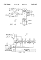
- FIG. 3 is a generalized top view of three adjacent traffic lanes using the AVI System of FIG. 1, the figure including a depiction of the timing sequence of a trigger pulse and interrogation signal from the interrogator to the transponder;
- FIG. 4 is a block circuit diagram of the transponder and interrogator arrangement usable in the systems of FIGS. 1-3;
- FIG. 5 is a more detailed block circuit diagram of the transponder of FIG. 4, depicting a modulation detector, a highpass filter, and a wake-up block;
- FIG. 6 is an even more detailed block circuit diagram of the elements of FIG. 5, including the modulation detector, the highpass filter and the wake-up block;
- FIG. 7 is a timing diagram showing the signals at labeled nodes of the transponder as shown in FIGS. 5-6;
- FIG. 8 is a block circuit diagram showing the interconnection of various function blocks of the Application Specific Integrated Circuit (ASIC) of FIG. 5;
- ASIC Application Specific Integrated Circuit
- FIG. 9 is a block circuit diagram of a receive buffer block preferably within the digital Application Specific Integrated Circuit (ASIC) of FIG. 8 for receiving signal "A" from the modulation detector;
- ASIC Application Specific Integrated Circuit
- FIG. 10 is a block diagram of the lane discriminator block preferably within the digital ASIC of FIG. 8;
- FIG. 11 is a block diagram of the main controller block preferably within the digital ASIC of FIG. 8;
- FIG. 12 is a block diagram of the main memory block preferably within the digital ASIC of FIG. 8;
- FIG. 13 is a block diagram of the transmit block preferably within the digital ASIC of FIG. 8;
- FIG. 14 is a block diagram of the external interface block preferably within the digital ASIC of FIG. 8;
- FIG. 15 is a block diagram of the buzzer block preferably within the digital ASIC of FIG. 8;
- FIG. 16 is a block diagram of the oscillator block preferably within the digital ASIC of FIG. 8;
- FIG. 17 is a block circuit diagram of an interrogator usable in the transponder and interrogator arrangements of FIGS. 1-3 wherein the interrogator is capable of sending a low frequency modulation signal to activate the transponder according to the present invention
- FIG. 18 illustrate waveform graphs for two different embodiments of "squitter” modulation by which low frequency signalling from the interrogator of FIGS. 1-4 can be superimposed upon an RF interrogation signal;
- FIG. 19 is a block circuit diagram of a transponder which also includes an RF threshold detector.
- FIG. 1 shows a block diagram of an AVI system 10 in which an interrogator 12 communicates with a remote transponder 14 by transmitting an interrogation signal to the transponder 14 in response to which the interrogator 12 transmits back to the interrogator 12 a response signal containing a transponder-unique identifying code (ID).
- ID transponder-unique identifying code
- the interrogator 12 will convey this ID code into a host computer (host) 16 for debit against the driver's account.
- host host
- the AVI system 10 preferably includes interrogator electronics 20 for control of the interrogator 12.
- multiple traffic lanes 28 are located at a traffic control point such as a toll plaza 29.
- Each traffic lane 28 has an associated interrogator 12.
- the interrogator 12 maintains communication via an RF data link with transponders 14 carried on vehicles 26 travelling within the interrogator's 12 associated lane 28.
- the interrogators 12 may have unique internal electrical parameters such as interrogator lane position, interrogator control parameters, and interrogator reference frequency.
- the role of the interrogator 12 in this application is: to trigger or activate a transponder 14, to interrogate or poll the transponder 14 for specific information, and to acknowledge to the transponder 14 that a valid data exchange has taken place. As shown in FIGS.
- the interrogator 12 has an antenna 18 which is preferably mounted approximately 18 feet above the ground.
- the antenna 18 will have circular polarization, but advantages may exist which will motivate the use of other choices of polarization including linear and elliptical.
- Interrogator electronics 20 are connected to the antenna 18 by suitable cable, such as for example an RF coax 22.
- the interrogator 12 communicates in a wireless fashion with the transponder 14 by sending on/off keyed modulated signals to the transponder 14. Interrogator 12 then sends a continuous wave RF signal to the transponder 14.
- the transponder 14 may respond to the interrogator 12 by backscatter modulating the continuous wave RF signal such as described in U.S. Pat. No. 4,739,328 by Koelle, et al. Details of the communication between the interrogator 12 and the transponder 14 will be further described herein.
- the function of the optional host 16 is to control the operations of the interrogator 12 and the peripheral functions of the toll plaza. Such peripheral functions might include operation of traffic control gates and other lane enforcement equipment such as cameras and traffic lights.
- Connection 24 between the interrogator 12 and the host 16 as shown in FIG. 1 may be an ethernet, token ring, RS232, RS422 or other connection.
- the interrogator 12 of FIG. 1 is housed in two modules: the electronics module 20 and the antenna 18. As shown in FIG. 4, the electronics module 20 contains a transmitter 52, a receiver 54, and a control circuit 56.
- the interconnection 22 between the antenna 18 and the electronics module 20 consists of a low-loss RF interconnect, which is typically a coaxial cable, and a multi-conductor cable capable of supplying power and control signal information.
- FIG. 2 shows a side view of a typical AVI system 10 installation.
- a vehicle 26 travels on a vehicle lane 28a-c and approaches the antenna 18.
- a transponder 14 is located on or within a vehicle 26.
- the transponder 14 is mounted to the vehicle front window.
- other locations such as on a truck's bumper might be appropriate to reduce variation in height of transponder 14.
- the vehicle 26 carrying the transponder 14 approaches the interrogator 18 at the toll plaza 29. Further details regarding the communication between the transponder 14 and the interrogator 12 will be discussed herein. The components of the interrogator 12 and transponder 14 will also be discussed in greater detail.
- FIG. 3 is a top view of an AVI system 10 comprising three lanes 28a-c.
- the three lanes 28a-c are shown merely for illustration purposes; this system 10 could be applied to one or multiple lanes.
- circuitry is provided in the interrogator 12 for determining in which of the lanes the transponder 14 is located.
- Claude A. Sharpe's U.S. patent appl. Ser. No. 08/021,123, assigned to Texas Instruments provides one such lane discrimination circuit and method.
- FIG. 4 provides a block diagram of the major components of the AVI system 10.
- the AVI system 10 preferably comprises directional antennas 18, each antenna 18 focused on an associated vehicle lane 28a,28b,28c.
- a vehicle 26 or vehicles 26 may travel on each lane 28a-c, each vehicle 26 carrying one or more transponders 14.
- Each transponder 14 preferably comprises: an antenna 30, an analog or analog/digital ASIC 32, a digital ASIC 34, and a modulated reflector 41.
- Antenna 30 and modulated reflector 41 may form a single integrated antenna 31.
- ASIC 32 and ASIC 34 are integrated as a single ASIC.
- the transponder antenna 30 is operable to receive RF transmissions from the interrogator 12.
- the analog ASIC 32 converts a signal supplied by the transponder antenna 30 to a voltage which upon exceeding a threshold activates the transponder 14.
- the analog ASIC 32 senses high frequency modulation present upon the signal from the transponder antenna 30 and will only activate the transponder 14 upon presence of that specific modulation frequency. In this way, the transponder is relatively immune being awakened by spurious RF transmissions not originating in the interrogator 12, but only is activated when a particular frequency is transmitted by the interrogator 12.
- the voltage threshold may be adjustable.
- transponders 14 only responds to interrogation signals from the interrogator antenna 18a-c positioned within the lane 28-c in which the vehicle 26 carrying the transponder 14 is travelling.
- the transponder 14 compares a first field strength pulse 44a received from the first directional antenna 18a to a second field strength pulse 44b received from the second directional antenna 18b.
- the transponder 14 may then respond to messages from the appropriate interrogator 12 (i.e., the interrogator associated with the lane 28a,28b, or 28c in which the transponder 14 is travelling).
- the appropriate interrogator 12 i.e., the interrogator associated with the lane 28a,28b, or 28c in which the transponder 14 is travelling.
- a similar procedure will be repeated between other lane pairs (e.g., 28a-28c, 28b-28c).
- the transponder 14 is then operable to demodulate a interrogation signal, which in the preferred embodiment is amplitude modulated, from the appropriate interrogator 12.
- the transponder 14 is then operable to backscatter modulate a continuous wave signal sent by the interrogator 12 to generate an response signal via a modulated reflector 41.
- the analog ASIC 32 and digital ASIC 34 typically process the interrogation signal received from the transmitter 52 and formulate the necessary reply data.
- the digital ASIC 34 then provides the properly formatted reply data stream to a modulated reflector 41.
- This ASIC 34 might be a simple digital system using a fixed format, or a more versatile digital processing system which can incorporate a number of options. Many options can be envisioned for the ASIC 34 to accomplish, examples include but are not limited to: data storage, data exchange history, and battery capacity warning.
- the modulated reflector 41 is modulated by changing its apparent wave length, preferably between one fourth and one half the carrier wave length. When the apparent wave length of the modulated reflector 41 is 1/2 ⁇ , then the antenna 30 should reflect a large portion of the incident carrier energy.
- the modulated reflector 41 When the modulated reflector 41 has an apparent length of b 1/4 ⁇ , it will reflect very little of the incident carrier. As is well known in the art, a switching of an antenna between 1/2 ⁇ and 1/4 ⁇ can be accomplished by connecting or disconnecting two 1/4 ⁇ stubs.
- the change in Reflective Cross Section (RCS) is preferably between 45 cm 2 and 100 cm 2 .
- RCS Reflective Cross Section
- the transponders 14 are typically self-contained on a small credit card size assembly that is completely portable. Preferably an internal battery is provided to give operating power to the transponder 14. Alternatively the transponder 14 might gain its operating power directly from the RF signal.
- the modulated reflector 41 is described as a separate element from the transponder antenna 30, it is possible for both elements to be integrated into a single integrated antenna 31.
- the interrogator 12 is located at a specific point where data exchange is desired, such as a toll plaza 29.
- the AVI system 10 may include a common reference oscillator 50 which generates at its output 51 a reference carrier wave for synchronization of the interrogators 12.
- Each interrogator 12 has a directional antenna 18 and a transmitter 52 which transmit a trigger signal 42 of sufficient field strength and/or modulation type at a pre-selected distance to trigger or activate a transponder 14 being carried in a vehicle 26 in the interrogator's associated vehicle lane 28.
- the preferred embodiment transponder 14 will be activated when a low power wake-up circuit 64 detects in the received signal a pre-selected modulation frequency.
- the wake-up circuit 64 if the wake-up circuit 64 receives the prescribed modulation signal, the wake-up circuit 64 will then apply clocks to the higher power consumption digital ASIC 34. In this fashion power is conserved because the wake-up circuit 64, which constantly monitors for trigger signals 42 (see FIG. 3), consumes much less power than the digital ASIC 34, which is only activated upon detection of a trigger signal 42 (see FIG. 3).
- the interrogator 12 After transmitting the trigger signal 42 (see FIG. 3), transmits an interrogation to the remote transponder 14. The interrogation is preferably transmitted using On-Off Keying.
- the transmitter 52 Upon completion of the interrogation, the transmitter 52 then transmits a continuous wave RF signal onto the transponder 14 so the transponder 14 may backscatter modulate the continuous wave RF signal to generate the response signal.
- the interrogator 12 further includes a receiver 54 for reception of the response signal and for separation of the response signal from spurious non-modulated reflections.
- the interrogator transmitter 52 and receiver 54 operate under control of a control interface circuit 56.
- the host 16 by way of the control interface circuit 56 directs the transmitter 52 to send the trigger signal 42, followed by the interrogation signal.
- a first interrogator 12a, second interrogator 12b, and third interrogator 12c send simultaneous first, second, and third interrogation signals, respectively.
- first interrogator 12a sends a first field strength pulse 44a and second or third interrogators 12b,12c send no RF energy.
- second interrogator 12b sends a second field strength pulse 44b while first and third interrogators 12a,12c send no RF energy.
- a third interrogator 12c sends a third field strength pulse 44c while first and second interrogators 12a,12b send no RF energy.
- a transponder 14 travelling in a vehicle 26 in one of the lanes 28a,28b,28c associated with each interrogator 12a,12b,28c can determine by comparing the amplitude of the pulses 44a,44b,44c received during the first, second, and third field strength periods 45,46,47, in which of the three lanes 28a-c it is travelling.
- the host 16 by way of the control interface circuit 56 is still further operable to direct the transmitter 52 to send the continuous wave RF signal following the interrogation and to simultaneously direct the receiver 54 to receive the response signal. This sequence can be extended to any number of lanes.
- the electronics 20 comprise a transmitter 52 that is operable to send signals to the antenna 18 for the interrogation of transponders 14.
- transmitter 52 receives signals from the host 16 via the host connection 24.
- the transmitter 52 transmits a continuous wave RF signal to the transponder 14, which then backscatter modulates the continuous wave RF signal with the reply data.
- the receiver 54 detects the reflected energy, which is backscatter modulated by the transponder 14, and separates the modulated signal from the non-modulated reflections.
- Antenna 18, shown here in electrical communication with the transmitter 52 and the receiver is a directional antenna 18 with a precisely shaped pattern and is used to radiate and receive RF signals covering a portion of each lane during the data exchange between the interrogator 12 and the transponder 14.
- a single antenna 18 is used for both the interrogation signal and the response signal.
- the antenna 18 is typically mounted approximately 18 feet above the roadway and is preferably positioned to ensure a constant link between the interrogator 12 and the transponder 14 regardless of site-dependent variations.
- the control circuit or host interface 56 used to communicate with the host 16, which may control all the interrogators 12 at a single toll plaza.
- the host interface 56 between the interrogator 12 and the host 16 for certain read/write operations accepts information from the host 16 via the host connection 24 and formats the data for transmission to the vehicle 26 by means of the transmitter 52. Preferably the communications with the host 16 will not occur until after the transmitter 52 has completed an entire read/write transaction with a transponder 14.
- the host interface 56 also decodes the reply data from the transponder 14 by means of the receiver 54 and supplies this reply data to the host 16.
- the antenna 18 is preferably weatherproof and designed to operate over the anticipated temperature extremes in its environment.
- interrogators 12 for multiple lanes one interrogator 12 will preferably be provided for each lane. All interrogators 12 at a toll location 29 will be coordinated in frequency, power output and antenna pattern to minimize overlap of coverage and interference between adjacent lanes.
- a different carrier frequency is typically used in each interrogators 12.
- adjacent interrogators 12 might have differing carrier frequencies to minimize interference as between the adjacent interrogators 12, while non-neighboring interrogators might use the same carrier frequency (i.e., where the interrogators are arranged spatially as #1, #2, #3, #4, #5, and #6, interrogators #1, #3, and #5 might use one carrier frequency while interrogators #2, #4, and #6 might use another carrier frequency).
- a common carrier frequency might be used in all interrogators 12, such as in a system which provides lane discrimination between transponders 14 as described in the co-assigned Sharpe U.S. patent application Ser. No. 08/021,123.
- the receiver 54 of the interrogator 12 detects the backscatter modulated return signal from the transponder 14.
- the amplitude and phase of the return signal will be completely dependent upon the multitude of reflections which occur from a number of sources.
- Undesired sources of return include the following: vehicles 26 in the same lane as the interrogator 12 creating beamfilling or non-beamfilling unmodulated returns; vehicles 26 in adjacent lanes 28a,28b,28c creating unmodulated and backscatter modulated returns; fixed obstacles of unknown composition creating unmodulated returns; and leakage from the transmitter 52 to the receiver 54 during transmission of the continuous wave RF signal to the transponder 14.
- interrogator 12 typically, one interrogator 12 is provided for each lane 28 in which a data link is to be enabled. Furthermore, except for site-programmable internal electrical parameters such as lane location, or other controlled parameters, all interrogators 12 are identical and are coordinated in time by a common reference oscillator 50.
- the interrogation signal is received in the analog ASIC 32 from the antenna 30.
- the modulation detector 70 acts to remove the carrier signal from the received interrogation signal and pass this to the first stage circuitry 62.
- the first stage circuitry comprises a lowpass filter 72 which removes high frequency components of the signal from the modulation detector 70.
- the output of the lowpass filter 72 is further transmitted to a threshold detector 68 that compares the output of the lowpass filter 72 to a reference voltage.
- the output of the threshold detector 68 will thus be a binary signal which will be an input signal, d in , to the digital ASIC 34 and to the wake-up circuitry 64.
- the inventive concepts described herein have significant advantages over the prior art in terms of power consumption. It is of significant importance to design a transponder 14 that consumpes minimal power. The importance of a power-efficient transponders 14 exists whether the transponder 14 is powered by a received RF signal or whether the transponder operates on a battery. By implementing the inventive concepts described herein, the transponder 14 will normally be in a sensing mode with a 1/24 duty cycle sleep mode, drawing little energy from the battery or RF energy source. The only energy consumed in this duty cycle sleep mode will be that required by the wake-up circuit 64.
- a high pass filter 74 is provided at the output of the detector 70 to filter out any spurious low frequency signals such as from cellular phones or other sources.
- the high pass filtered signal is provided from the filter 74 at node "D."
- the filter 74 may alternatively be a band pass filter.
- filter 74 may be a low pass filter when the transponder is activated by a low frequency (LF) modulated signal.
- LF low frequency
- the wake-up circuit 64 Upon detection of an RF modulation of the frequency of interest by modulation detector or pulse counter 78, the wake-up circuit 64 sends an enable signal, "F,” to OR gate 97 which will in turn send a wake -- up signal to the digital ASIC 34 so long as either "F” the clock signal to the digital ASIC 34 to enter an active state.
- the expected modulation frequency will be the high-speed modulation of approximately 100 kHz to 400 kHz.
- a low frequency signal of below approximately 1000 Hz is superimposed upon the 915 MHz carrier and this is the modulation signal expected by the pulse counter 78.
- the pulse counter 78 is preferably a gated 5 bit counter circuit.
- the gate is set at a specific frequency so that a range of valid counts is detected.
- the wake-up circuitry 60 is shown in still greater detail. If modulation is detected, the digital ASIC 34 is activated and the pulse counter 78 is kept active by an "assert" signal from the main controller block 140 (see FIG. 11) of the digital ASIC 34. If the modulated RF signal disappears, the main controller block 140 by the "assert” signal may keep the wake -- up signal from OR gate 97 active until the digital ASIC 34 functions are completed. The main controller block 140 will not disable the wake -- up signal from OR gate 97 until all pending functions are completed.
- the detector 70 preferably comprises a diode 82 which receives and rectifies the signal at node "A" from the antenna 30.
- a shunt capacitor 84 and shunt resistor 86 act to form a low pass filter having a known time constant so that the 300 kHz Manchester modulation can be extracted from the 915 MHz continuous wave RF signal.
- a high pass filter 74 then acts to filter out any undesirable low frequency components,
- the high pass filter 74 comprises a series capacitor 88 and a shunt resistor 90. It is important to understand that the component values of the detector 70 and the high pass filter 74 are selected depending on the modulation frequency that must be detected to enable the digital ASIC 34 by signal "F", (FIG. 4). In other words, the high pass filter 74 may have a very low corner frequency or may be eliminated altogether if the wake-up circuit 64 is expecting a modulation frequency that is lower.
- gated comparator 92 receives clock signals from the pulse generator 76 on node "E.”
- the input from the pulse generator 76 serves to gate the voltage pulses from node “D.”
- gated latch 96 serves to provide a high input to an 0R gate 97 that performs a logical OR of the "F” signal and an assert signal from the main controller block 140.
- the "F” signal is asserted once the correct count has been reached and until the falling edge of the gating pulse from the pulse generator 76 resets the gated latch 96.
- the gated latch 96 serves to provide a high input to a OR gate 97.
- the output of OR gate 97 provides a "wake-up" signal to the digital ASIC 34 (see FIG. 5).
- FIG. 7 a timing diagram for a preferred embodiment modulation detector is shown.
- the signal at node “D” is shown as a continuous wave 915 MHz signal with 300 kbps Manchester II On-Off Keying (OOK) superimposed. Bursts of 300 kHz modulation occur on the signal at node “D” as the high pass filter removes the 915 MHz carrier signal from the node “A” signal.
- OLK On-Off Keying
- FIG. 8 illustrates an overview of the functional blocks 100,108,140, 148,155,172,190,214 within an embodiment of the digital ASIC 34.
- a clock block 214 receives a wake -- up signal from the analog ASIC 32, and thereupon begins to generate clock signals, preferably at 3.6 MHz, 1.2 MHz, 0.6 MHz, and 0.3 MHz. These clock signals are transmitted to the above functional blocks, including at least the main controller block 140.
- the clock block 214 preferably continues generation of the clock signals, regardless of the status of the wake -- up signal received from the analog ASIC 32, until receiving a clk -- disable signal from the main controller block 140.
- CMOS digital logic is that it draws power only when changing states, or to a lesser degree when it is being simply being clocked; therefore, the static current drain of all the digital CMOS logic with the clocks will be very small (in the nano amp range).
- the receive buffer block 100 receives a data-bearing signal, d in , from the analog ASIC 32.
- the receive buffer block 100 decodes this signal autonomously from the main controller block 140 and is operable to transmit received data to the main controller block 140 or to main memory block 148.
- the decoded signal can be received by the main controller block 140 without buffering via the signal, incoming -- data.
- the decoded signal can be stored and buffered in the receive register 122 (not shown, see FIG. 9) and accessed by the main controller block 140 sending an address signal radr -- 11.
- the data output rdat -- 11 of the receive register 122 see FIG.
- the receive buffer block 100 may be received directly by the main controller block 140, or it may be received by the main memory block 148 for storage therein.
- the receive buffer block 100 preferably also provides an incoming -- msg signal to notify the main controller block 140 that an interrogation is being received. Furthermore, the receive buffer block 100 may provide a msg -- valid signal to the main controller block 140 to inform it that the interrogation was received without received error.
- the receive buffer block 100 also might provide a signal, manch -- active, to the lane discrimination block 108 to notify the lane discrimination block 108 that the receive buffer block 100 is actively decoding the data-bearing signal, d in .
- the lane discrimination block 108 is operable to receive d in and manch -- activity and determine in which vehicle lane 28 (FIG. 3), the vehicle 26 is travelling.
- the details of this lane discrimination block 108 is described more fully below and in Claude A. Sharpe's U.S. patent application No. 08/021,123, assigned to Texas Instruments.
- the lane discrimination block 108 upon determination of the vehicle lane 28 (FIG. 3) in which the vehicle 26 (FIG. 2) is travelling, may transmit this information to main controller block 140 as the signal, lane -- #.
- the main memory block 148 shown in FIG. 8 is operable to store data received from the receive buffer block 100 as mentioned above. Further, the main memory block 148 is operable to receive data from an external microcontroller (not shown) via the external interface block 172. This data exchange is via the addressing signal, radr -- 22 and via the data signal, rdat -- 22. The main memory block 148 may also receive data sent from the external microcontroller (not shown) via address and data signals, ⁇ C -- adr and ⁇ C -- dat, respectively. The main memory block 148 is may be enabled or disabled by the main controller block 140 by the select signal.
- the external interface block 172 operates as an interface between the main memory block 148 and an external microcontroller (not shown).
- the external interface block 148 receives an enable signal from the main controller block 140 and a clock signal from the clock block 214.
- the clock signal is 1.2 MHz.
- the external interface block 172 communicates with the external microcontroller (not shown) by a serial -- clk signal, a serial -- I/O signal, and a number of handshaking signals ( ⁇ C -- rdy, R -- /W, and ext -- assert) which will be described in more detail in the description with respect to FIG. 14.
- a transmit block 155 is also shown in FIG. 8.
- the transmit block 155 operates under control of the main controller block 140 to transmit data in a response signal to the interrogator 14 (not shown, see FIG. 1) by preferably backscatter modulating the data upon a continuous wave RF signal from the interrogator 14 using backscatter modulator 41.
- the transmit block 155 receives data from the main memory block 148 via the data signal rdat -- 21 and addresses the main memory block 148 using the address signal radr -- 21.
- the transmit block 155 communicates with the main controller block 140 using signals (xmit -- data -- select, start, xmit -- complete, and trans -- count) which will be described in more detail in the description with respect to FIG. 14.
- a buzzer block 190 shown in FIG. 8 operates to transmit indicating tones to an operator via a buzzer 212.
- the buzzer block 190 operates under control of the main controller block 140.
- the main controller block 140 sends control signals beep -- type, beep -- enable, beep -- start to the buzzer block 190. These control signals will be described in more detail in the description with respect to FIG. 15.
- the transponder 14 upon completion of a successful transaction comprising an interrogation and a response in which no data errors occurred, the transponder 14, for example, might enter a 10 second period during which it will not respond to further interrogations having the same agency code as the just-completed transaction. Interrogations received during this nonresponsive period will be compared to the previous agency code, and will not be responded to if the agency code is the same as the previous agency code. If a different, valid agency code is received during the nonresponsive period the transponder 14 may respond to the new interrogation.
- the receiver block 100 contains a Manchester decoder 102, CRC-CCITT calculator 106, and a state controller 110.
- the receiver block 100 will decode transmissions from the interrogator 12, determine in which lane the transponder 14 is located, and calculate the incoming message's CRC.
- the Manchester decoder 102 receives data-bearing signal, d in , from the analog ASIC 32.
- the Manchester decoder 102 comprises a digital phase-locked loop at 3.6 MHz to enable the Manchester to synchronize to d in .
- the Manchester decoder 102 provides at its output a received serial data stream, SRDT, and a clock signal, SRCK, derived from the data-bearing signal, d in .
- the manchester decoder 102 also provides a manch -- activity signal to the lane discrimination block 108 (see FIG. 8). The purpose of the manch -- activity signal will be later described with respect to FIG. 10.
- the serial data stream, SRDT is fed into a CRC generator 106.
- the CRC of the incoming message is calculated using the CCITT polynomial (X 16 +x 12 +x 5 +1).
- the receive controller 110 determines which data bits are calculated in the CRC (the overhead bits are not calculated as part of the CRC) and activates the CRC generator 106 to begin calculating the CRC after the overhead bits have all been received.
- a byte counter 114 is provided to receive the serial data stream and count the number of bytes received. The number of bytes may be counted by incrementing the byte counter 114 with every eighth pulse of the serial data clock and transmitting the count to the main controller block 140 (see FIG. 8).
- An eight-bit holding register 116 is provided for holding bytes as they are transmitted from the serial-to-parallel shift register 112.
- a data comparator 120 is provided so the receive controller 110 can compare data from the serial-to-parallel shift register with that stored in a SRAM 118.
- the transponder identification might be stored in the SRAM 118 and compared to an ID code gleaned from the serial data, SRDT by the receive controller 110 via the serial-to-parallel shift register 112.
- the receive buffer block 100 operates autonomously from the main controller 104.
- the receive controller 110 senses received Manchester-encoded data on the manch -- activity line from the Manchester decoder 102.
- the receive controller 110 is further operable to bypass the CRC generator 106 or to reset the CRC generator 106 using control lines crc -- bypass and crc -- clear.
- the controller 110 Upon sensing the start of receipt of Manchester-encoded signals, the controller 110 preferably resets the CRC generator 106 and resets the byte count register 114.
- the controller 110 may control the receive register 122 to store data from the eight-bit holding register 116.
- the lane discrimination block 108 includes a lane discrimination controller 124 that samples at three specific times after the interrogation of the transponder 14 by the interrogator 12 is initiated (see FIG. 3).
- the lane discrimination controller 124 stores voltage samples from node "B" of the analog ASIC 32 (see FIGS. 5, 8) in capacitors 126a, 126b, 126c, whose voltages become inputs to an voltage comparator/decoder 130.
- the lane discrimination controller 124 samples node "B" during sample periods 45,46,47 (see FIG. 3) to sample field strength pulses 44a-c (see FIG. 3).
- Switches 132a,134b,132c connect the capacitors 126a,126b,126c, respectively, to the node "B" input voltage (see FIGS. 5, 8).
- the output of the comparator 130 is sampled a specific time later (after settling) to determine which signal was stronger, and therefore in which lane 28a,28b,28c the transponder 14 is located.
- the lane discrimination block 108 is preferably autonomously operable to sample the field strength pulses without need for supervision from the main controller block 104 (see FIG. 8) or other controllers.
- a short timer 137 provides 3.3 ⁇ s sample timing between the pulses. Using this 3.3 ⁇ s timing, the lane discrimination controller 124 is properly synchronized to the sample periods 45,46,47 (see FIG. 3). It should be understood that the timing periods described above are merely exemplary and that other periods may be used depending on system design parameters such as the number of lanes being discriminated between and the length of the interrogation and timing pulses.
- the main controller block 140 controls the overall actions of the digital ASIC 34.
- the main controller 104 is awakened by the "wake-up" signal from the analog ASIC 32 (see FIG. 8).
- the main controller 104 then makes decisions based on the incoming message content and the current transaction sequence.
- the comparator 142 takes the incoming messages from the receive buffer 122, verifies the validity of the received message using the calculated CRC, and performs comparisons on the incoming message information.
- the main controller 104 executes the appropriate command sequence.
- a Record Type Code (16 bits) of the incoming interrogation is used to determine the order and type of comparisons performed.
- This code uniquely defines the transponder message fields and functions permissible. By way of example, hexadecimal numbers 1 through 7FFF may be set aside for transponder message structures and 8000 through FFFF may be dedicated for reader-to-transponder message structures.
- the Record Type Code is examined and the comparator circuit 142 sets flags in accordance with the Record Type Code.
- the main controller 104 acts upon the flags generated by the comparator circuit 142 and takes the appropriate actions to analyze the data content of the interrogation, to generate the data for the transponder's 14 responses, and to signal the optional external microcontroller (not shown) or to perform ASIC maintenance functions (discussed below under the heading "MAINTENANCE MODE AND MESSAGES").
- the main controller 104 also acts to load the main memory block 148 (see FIG. 8) with information by providing addresses to the main memory block 148 in which to store data. Typically the source of this data would be the received interrogation or the external microcontroller (not shown).
- transaction counter 146 is an 8 bit counter which is incremented at the end of an acknowledgment message from the interrogator 12 (see FIG. 1) if the transaction was successfully completed (e.g., the interrogator 12 received a valid ID code from the transponder 14).
- the transaction counter 146 though part of the main controller 104, is addressed within the address space of memory block A.
- the transaction counter 146 provides a circulating 8 bit number which can be used to track successful toll transactions and maintenance operations for bookkeeping purposes (much as a "check number" keeps track of personal bank transactions).
- the value of the transaction counter is not normally programmed, but may be reset to zero by resetting the ASIC via the external reset pin or by another method.
- the main controller 104 acts somewhat as a nerve center for the transponder 14. Many of the control signals pass to and from the main controller 104 to the other function blocks 100,108,140, 148,155,172,190,214.
- the main controller 104 receives its timing from the exemplary 3.6 MHz clock from the clock block 214.
- the clock block 214 preferably continues generation of the clock signals, regardless of the status of the wake -- up signal received from the analog ASIC 32, until receiving the clk -- disable signal from the main controller 104.
- the main controller 104 may receive data from the receive buffer block 100 either without buffering via the signal, incoming -- data.
- the decoded signal can be stored and buffered in the receive register 122 (not shown, see FIG. 9) and accessed by the main controller block 140 sending an address signal radr -- 11.
- the main controller 104 is also operable to store data in main memory block 148 by sending address signal wadr -- 21 and by enabling main memory block 148 by the "select" signal.
- Main memory block 148 once so selected, will be operable to receive data directly from the receive buffer block 100 by signal rdat -- 11.
- the receive buffer block 100 preferably also provides an incoming -- msg signal to notify the main controller block 140 that an interrogation is being received Furthermore, the receive buffer block 100 may provide a msg -- valid signal to the main controller block 140 to inform it that the interrogation was received without received error.
- the main controller 104 receives a signal, lane -- #, from the lane discrimination block 108 to determine in which vehicle lane 28 (FIG. 3) the vehicle 26 bearing the transponder is travelling (see FIG. 2).
- the transmit block 155 operates under control of the main controller block 140 to transmit data in a response signal to the interrogator 14 (not shown, see FIG. 1) by preferably backscatter modulating the data upon a continuous wave RF signal from the interrogator 14 using backscatter modulator 41.
- the transmit block 155 receives data from the main memory block 148 via the data signal rdat -- 21 and addresses the main memory block 148 using the address signal radr -- 21.
- the transmit block 155 communicates with the main controller block 140 using signals (xmit -- data -- select, start, xmit -- complete, and trans -- count) which will be described in more detail in the description with respect to FIG. 14.
- the main controller 104 controls the buzzer block by control signals beep -- type, beep -- enable, and beep -- start. These control signals will be described in more detail in the description with respect to FIG. 15.
- the main memory 150 shown in FIG. 12 has memory blocks A, B, C, D and M.
- each of the exemplary five blocks of memory is available for transmission to the interrogator 12 by the transmit block 155 (see FIG. 8).
- the memory 150 is preferably a multi-port SRAM, allowing simultaneous read and write operations.
- memory 150 is a SRAM having a capacity of 80 bytes, however, memory 150 might be non-volatile memory (e.g., EEPROM, ROM). Further, memories having more or fewer than 80 bytes could be implemented in an AVI system or other systems in accordance with this invention.
- the selection muxes 152,154 allow writing to the memory from the main controller 104, from the external microcontroller (not shown) through the external interface block 172.
- the interrogator 12 may ask the transponder 14 for a 16 byte data transmission of memory block A, B, C, D, or M.
- the interrogation message might instruct the transponder 14 to send a longer burst of data, such as 32 byte data transmission.
- a 32 byte data transmission might comprise consecutive transmissions of memory blocks A and B, or of memory blocks A and C, or of memory blocks A and D, or of memory blocks A and M.
- each of the memory blocks (A,B,C,D,M) might be, for example:
- Memory block A basic accounting information
- Memory block B law enforcement information
- Memory block C tollway open-entry information storage
- Memory block D microprocessor output data transmit buffer
- Memory Block M maintenance and control functions.
- the transaction counter 146 is part of the main memory's addressing space, because of its logical relationship to the main controller block 140, it is included in FIG. 11 and the description thereof.
- the second special register in memory block A is the FLAGS register. This 8 bit register indicates the capabilities of the transponder 14 to the interrogator 12, and certain bits are programmed by a service center.
- the individual bits of the FLAGS register are defined as:
- Bits 0 and 2 are information bits for the Reader and set at the service center. Bits 1 and 3 reflected enabled or disabled ASIC circuitry, and are set at the service center. Bit 4 is set by the interrogator 12, but may be reset at a service center. Bits 7 and 6 are the high-order bits from the battery consumption meter.
- memory block B may be "free-form" or not rigidly specified as is memory block A.
- the contents of memory block B (16 bytes) may be written at the service center by the toll agency or other authorized entity, but can be read by the reader 12.
- Memory block B may, for example, contain read-only type information (law enforcement info, license plate number, transaction agency code, etc.).
- the structure of memory block C may also be "free-form."
- the purpose of this memory block is to pass information (such as tollway entry info) from one reader to another interrogator 12.
- a first interrogator 12 may store information in the transponder 14 by sending data which the main controller block 140 (see FIG. 8) can store in memory block C by sending the appropriate addressing information.
- Another, subsequent interrogator 12 may then by sending an appropriate Transaction Record Type Cod (such as the Type 3A, described below, under the heading "Transaction Record Type Codes) read the contents of memory block C.
- Transaction Record Type Cod such as the Type 3A, described below, under the heading "Transaction Record Type Codes
- Memory block D is intended to be used by the main controller 104 as a transmit buffer (16 bytes) for information from an optional external microcontroller (not shown) to a interrogator 12 or a service center.
- the contents of memory block D (16 bytes) is primarily intended to be loaded by the external microcontroller (not shown). If an external microcontroller (not shown) is not present in the AVI system 10, block D can be used "free-form" as another 16 bytes of information which can be loaded by the service center or interrogator 12, and read by a service center or reader 12.
- block D might be used as additional storage in normal operations even with a microcontroller present.
- the transmitter block 155 contains a mux 156, a byte register 158, an encryption circuit 160, a CRC generator 162, a header generator 164, an FSK modulator 166, and a controller 168.
- the serial data stream to be transmitted is encrypted by the encryptor 160, passed through the CRC generator 162, and transmitted via the FSK modulator 166.
- the transmitter block control circuitry 168 is enabled. The transmitter controller 168 then transmits the "selsyn" signal, which may be used by the receiver 54 within the interrogator 12 to self-synchronize (selsyn) with the transponder 12 response.
- An exemplary selsyn signal might the binary and hexadecimal values: 10101010 and AA, respectively.
- the transmitter controller 168 Upon completion of sychronization with the interrogator receiver 54, the transmitter controller 168 then signals the main controller 104 for the appropriate memory block data to be clocked in at 300 khz. When the main controller 104 signals the end of data, the CRC circuit 162 clocks out the CRC. Upon completion of the transmission of the CRC bits, the transmitter block 155 enters the idle state and signals the main controller 104 to disable the transmitter clock block 214 for lowest power consumption.
- the encryption circuit 160 uses multiple keys.
- the encryption function may be deactivated at the service center.
- the CRC generator 162 calculates the CRC using the CCITT polynomial (x 16 +x 12 +x 5 +1).
- the data input to the CRC generator 162 is the encrypted data stream.
- the CRC value is always transmitted as unencrypted information.
- FIG. 14 shows an external controller interface circuit 172.
- the interface circuit 172 provides flexibility in the transponder 14 design, allowing future upgrades to the system with minimal effort.
- the interface circuit 172 allows an external microcontroller (not shown) to communicate with the transponder 14.
- the interface controller 174 may be activated by the main controller 104 by the "enable" signal between the two functional blocks (see FIG. 8). When awakened by the external microcontroller, the interface controller 174 senses that the "ext -- assert" signal is active and will proceed to communicate with the external microcontroller.
- the interface circuit 172 overcomes problems with designing the transponder 14 for future compatibility with unknown external circuitry having unknown future interface requirements.
- a buffer memory comprising an 8 bit shift register 186 and a 38 bit shift register (146 bit shift register) 184 is provided.
- the interface controller 174 forms the heart of the interface circuit 172.
- the transponder 14 communicates with the external microcontroller.
- the interface controller 174 receives messages from the main controller 104 via the control line ⁇ C -- MSG and will wake up the external microcontroller with the signal ⁇ C -- RDY.
- Data is loaded from the main memory 150 into the 8 bit shift register 186. Once a byte is loaded in parallel into the 8 bit shift register 186, the 8 bits are then circulated serially into the 138 bit shift register through the mux 180.
- mux 180 The function of mux 180 is to allow data to be clocked into the 138 bit shift register 184 from the 8 bit shift register 186 or to allow it to be clocked in from the external microcontroller via the serial I/O buffer 178.
- the mux 180 When the "circulate" signal is low-asserted, data passes through the mux 180 from the serial I/O buffer 178.
- the "circulate" signal When the "circulate" signal is high-asserted, data passes through the mux 180 from the serial output of the 8 bit shift register 186.
- the data can be loaded into the 8 bit shift register 186 in groups of 8 and circulated about into the 138 bit shift register 184 until the message is completely loaded. Once the message is completely loaded, the "circulate" signal is low-asserted.
- the interface controller 174 may be activated by the external microcontroller by raising the "ext -- assert” signal, whether or not the external RF field has activated the transponder 14. In either case, the interface controller 174 sends a seven bit address, RADR -- 22 to the main memory block 148 so that data can be loaded into or out of the 8 bit register 186 via RDAT -- 22.
- One of the advantages of having an interface circuit interposed between the main controller 104 and an external microcontroller is that by buffering and by design of the clocking to the 146 bit register 186,184 the external microcontroller is free to send its own serial clock signal to mux 182 for clocking data into or out of the 146 bit register 186,184. As shown in the figure, the interface controller 174 directs the mux 182 to pass either this serial clock from the external microcontroller or to pass its own clock to the 146 bit register 186,184. Flexibility thus exists to load and unload data into the register at any practical clock rate of the external microcontroller.
- Serial I/0 buffer 178 can enable data flow either direction, the direction depending on its single control line, DIR, from the interface controller 174. Further, not only is the external microcontroller capable of awakening the transponder 14 by the "ext -- assert" line, the interface controller 174 can awaken the external microcontroller by signaling over the uc -- rdy signal output.
- a bit-count circuit 176 monitors the incoming data stream and serves to orient the interface controller 174 to the start of data in the circulating shift register 184. The function of the interface controller 174 is to read and write 16 bytes of data to/from the optional, external microcontroller and to serially program (configure) the analog ASIC 32.
- the interface controller 174 is capable of direct communication with the main memory 150 through the buses ⁇ C -- MSG, and through the buses RADR -- 22[0:6](address), DATA[0:7](data), and ⁇ C -- ADR[0:7].
- a three bit command word is loaded first into the 8 bit register 186.
- the three bit command word informs the external microcontroller the nature of the ensuing message.
- the bytes of information that follow are loaded one byte at a time and then are shifted out and circulated through the mux 180 into the 138 bit shift register. After the ensuing message has been completely loaded, the shift registers 184,186 are clocked until the original two bits are again located at the beginning of the 8 bit register 186.
- the clk -- select line may asserted so that the serial clock from the external processor can be used to clock the data out of the shift registers 184,186, the control line into the serial I/O buffer 178 is asserted to allow data to be output, and the uc -- rdy is asserted to wake up the external microcontroller.
- the external microcontroller In a first mode, upon awakening, the external microcontroller has the R -- /W signal set low. The external microcontroller will then serially shift in the first three bits to determine the nature of the ensuing message. After the external microcontroller has clocked in as many bits as required from the three bit message from the transponder 14, the microcontroller sets its R -- /W signal high to indicate that it has completed receiving data.
- the interface processor Upon seeing the R -- /W signal asserted high, the interface processor sets the serial I/O buffer 178 to input mode, asserts the circulate signal low so data can again be loaded into the shift registers 184,186 in a circular fashion, and the clock signal is again set to the interface controller 174 so it may again take control of the loading and unloading of the shift register 184,186.
- the external microcontroller can wake up the interface controller 174 by the "ext -- assert" signal.
- the interface controller 174 sets the clock mux 182 to pass the serial clock from the external microcontroller.
- the R -- /W is asserted high.
- the external microcontroller will then shift data serially directly into the 138 bit shift register 184 and will continue until it has sent the necessary data and until the data has been shifted 146 times to load the first bit of the message into the 8 bit shift register 186.
- the interface controller 174 can then again take control of the clock by asserting the clk select line low to the clock select mux 182.
- Data can then be loaded out of the 8 bit shift register 186 into block D the main memory 150.
- the data is extracted one byte at a time, after which the clock transitions eight times to serially shift a new byte from the 138 bit register 184 into the 8 bit register 186. Unloading and shifting continues until the entire message has been transferred into the main memory 150.
- the preferred embodiment ASIC 34 uses the CALTRANS specification for its communications protocol.
- the CALTRANS specification is specific to many aspects of the message content, and the ASIC command structure complies with the CALTRANS requirements.
- the Reader 12 commands the transponder 14 through the use of 4 bytes: the record type (2 bytes) and the status code (2 bytes).
- the record type is sent as the first 2 bytes following the header in the POLL and the ACKNOWLEDGE messages, and the status code is included as part of the ACKNOWLEDGE message only.
- FIG. 14 in connection with the specification herein illustrates the ASIC interface circuitry for interfacing with an external microcontroller.
- the record type consists of the first two bytes following the header in each POLL and ACKNOWLEDGE message. It may act as a function in itself, or additional commands may be sent via the use of the status code (in the ACKNOWLEDGE message).
- the basic function of the record type is to tell the receiver (transponder or Interrogator) how to decode the fields in the message that it has just received, and to deliver to the ASIC an instruction to perform.
- the CALTRANS specification requires that a record type code range of 0x0001 through 0x7FFF will be reserved for transponder-to-Reader messages, and the record type code range of 0x8000 through 0xFFFF will be reserved for Reader-to-transponder messages.
- the 16 bit status code from the ACKNOWLEDGE message is encoded with special fields.
- the first three bits (MSB's) are coded as:
- the agency code represents the two bytes transmitted after the record type in the POLL message, and it consists of the MSB byte and the LSB byte.
- the ASIC 34 will have the ability to store two bytes of user-defined agency code for these comparisons.
- the user-defined agency code in the ASIC might be 0x5061 with the group response code of 0xFF.
- the incoming Agency code would have to be either 0x5061 or 0x50FF. Any other incoming Agency code would not cause the ASIC to respond immediately. If these conditions are not met, a microcontroller message will be generated. The microcontroller will then check its internal list of valid agency codes, and modify the ASIC's 34 user-defined agency code to that of the incoming agency code (if appropriate). After modification of the transponder's 14 user-defined agency code registers and account balance registers, the transponder 14 would be able to respond to the interrogator 12.
- the transponder 14 will have the issuing agency's identification programmed into its account number. It will be a lane controller or interrogator's 12 responsibility to verify the true validity of the transponder account for the given situation, and to make the proper transaction.
- the ASIC 34 typically expects the transaction to be completed in the same cycle (i.e. during the same WAKEUP-POLL-ACKNOWLEDGE sequence). However, if the agency code "silence" period of the POLL message is still in effect, the ASIC will listen to the ACKNOWLEDGE message for a special Type 9 ACKNOWLEDGE message containing it's account number for possible turn-on.
- the digital ASIC 34 contains a power-up reset circuit to properly initialize the circuitry upon connection to a battery.
- An external reset pin is also provided to allow a manual reset to initiated during maintenance operations/testing.
- the external reset pin may be grounded to initiate a reset, and this will cause the digital ASIC 34 to lose all previously programmed data and clear all counters and registers.
- Battery Consumption Gauge The battery consumption for powerup stages 2 and 3 is measured by a special conversion/calculation circuit on the digital ASIC 34. The battery consumption by these two stages are counted in a special register whose two high-order bits are included as part of the FLAGS register. The status of the two (MSB) bits indicate:
- the preferred embodiment digital ASIC 34 has the ability to drive a piezoelectric transducer to allow audible tones to be generated in response to certain transponder functions.
- a high beep (1172 hz) might indicate a successful function.
- a low tone (586 hz) generally might indicate an unsuccessful function.
- a long tone is approximately 3/4 second (872 ms) long, and a short beep is approximately 1/4 second (218 ms) long, both with approximately 1/2 second (436 ms) spacing.
- a maintenance mode is provided in which the toll agency or other authorized entity can fixedly store user information into the transponder's memory.
- This information includes: the type of encryption; whether encryption is used; whether lane discrimination is implemented; the FSK frequencies used; in transit information about the payload, such as weight, value, or toxicity; whether a microprocessor is attached to the transponder 14; the user account #; the amount of money stored on the transponder 14.
- the transponder does not become activated until an authorized individual puts the transponder into maintenance mode at a programming station by sending an access code.
- the transponder or transponder 14 may provide a maintenance mode acknowledgement signal to the interrogator 12, the maintenance mode acknowledgement signal for confirming to the interrogator that the transponder is in maintenance mode.
- the agency programs the transponder with user information. A change of agency code or the expiration of the 10 second timer will cause the maintenance mode to cease.
- the following functions are valid only if the maintenance mode is in effect.
- the lane discrimination controller 124 is disabled.
- the special message formats used for testing of the ASIC in maintenance mode include:
- the transponder is requested to send memory blocks A and B in the next RESPONSE message.
- the transponder is requested to send memory blocks A and C in the next RESPONSE message.
- the transponder is requested to send memory blocks A and D in the next RESPONSE message.
- the transponder is requested to send memory block A in the next RESPONSE message.
- the transponder is requested to send memory block A and the maintenance block.
- the battery consumption gauge clock is disconnected, the registers are loaded with test data, the registers are incremented by one clock, and the register values are read out in the RESPONSE message.
- the original contents must be saved, a new value calculated, and the new value stored into the battery consumption registers before the transponder is put back into operation.
- the transponder will respond with a Type 2 RESPONSE message.
- the transponder is requested to send the entire contents of the RECEIVE buffer.
- This special POLL message format is used to directly load the RECEIVE buffer with test data.
- the transponder will respond with a Type 6 RESPONSE message, which will be unencrypted.
- the transponder is responding with memory blocks A and the maintenance block.
- the transponder is responding with memory block A and the contents of the RECEIVE buffer. This message is unencrypted, and does not contain the tag's account number.
- the interrogator will have stored the account number of the tag from a previous POLL/RESPONSE sequence, and will use the account number in the corresponding ACK message for this response.
- the message following the status code is to be loaded into memory block D.
- the status code is ignored.
- the message following the status code is to be loaded into memory block C.
- the status code is ignored.
- the message following the status code is to be loaded into memory block B.
- the status code is ignored.
- the message following the status code is to be loaded into memory block A.
- the status code is ignored.
- the status code indicates the nature of the instruction.
- the bounce bit is reset. No other operation is performed. The status code is ignored.
- FIG. 18 Another embodiment interrogator is shown in FIG. 18. This configuration may be used to lower power consumption of the transponder by using a low frequency modulation superimposed on the normal RF interrogations. By using this low frequency modulation, it is possible to construct the field detector or wake-up circuit 64 to be sensitive to a very low modulation frequency such as 90 Hz instead of the normal communication modulation frequency.
- the interrogator 12 superimposes this low frequency modulation conceptually by a heterodyne or mixer 222 as shown in FIG. 18. The actual superimposition of this low frequency modulation could be using post-processing of the RF interrogation signal, such as the mixer 222 as shown in FIG. 18.
- the superimposition could be integrated into the generation of the RF interrogation signal, such as by using a technique called "squitter” modulation.
- This is a technique by which a high data rate signal can be made to contain low frequency components for signal sensing purposes.
- the data transmissions are thus sent in bursts having a burst rate equal to the low frequency signal to be detected. For example to achieve a 100 Hz low frequency (LF) component, data may be sent for 5 ms then remain in an known state (high or low) for another 5 ms. Then further data would be sent for another 5 ms followed by another 5 ms of "no data".
- LF low frequency
- Such a pattern is continuously repeated, creating a spectral line at 100 Hz that may be detected by a simple low pass filter 74 which passes 100 Hz and rejects the higher frequency signals.
- This squitter modulation technique would preferably be implemented in the software resident in the host 16, the transmitter 52, or the interface circuit 56.
- Alternative transmission formats instead of the square wave gating function described above are possible.
- the square wave gating function has periods of "transmit” alternated with “no transmit” (such that the transmission rate modulates between 0% and 100% of the maximum). The length of the data "no transmit" period can be increased in a linear manner from a minimum period to a maximum period.
- Such modulation would provide additional means for a receiver to recognize an interrogator signal and exclude interference sources.
- Other secondary modulation waveforms such as a sine wave could be utilized in this application.
- the motivations for using a LF modulation as the field detection signal include, as previously mentioned, a savings in power consumption. To build a sensitive field detector or wake-up circuit 64, amplifications of the received signal must occur after detection.
- the amplification is to the DC detected level, no immunity is provided to interference from external sources such as cellular phones, lightning, electric fences and other sources. Detecting a high speed modulation frequency draws a greater amount of power than might otherwise be required. The amplifier's power consumption is nearly linear with frequency, so it is important to lower the frequency the amplifier detects insofar as possible.
- the alternative preferred embodiment transponder will have a multi-state wake-up by which a low power stage 1 threshold detector 62 will wait for the received field strength to be greater than 500 mV/m2. Upon reception of a field strength in excess of the threshold, the stage 1 threshold detector 62 will enable the stage 2 wake-up circuit 64 to awaken and monitor the received signal for a pre-selected modulation. If the stage 2 wake-up circuit 64 receives the prescribed modulation signal, the wake-up circuit 64 will then turn on the digital ASIC 34 via switch 98. In this manner, minimum power is consumed because the stage 1 threshold detector 62 consumes but a small amount of power although it is always in a powered condition.
- the wake-up circuit 64 consumes a slightly greater amount of power, but is essentially a low-power device.
- the wake-up circuit 64 further is only component enabled during the normally small amount of time during which the received power is greater than the threshold. Finally, if both the threshold condition and the modulation condition are satisfied, only then is power applied to the higher power consumption digital ASIC 34.
- the interrogator 12 then transmits a interrogation signal to the remote transponder 14, the interrogation signal preferably being transmitted using On-Off Keying.
- the transmitter 52 Upon completion of the interrogation signal, the transmitter 52 then transmits a continuous wave RF signal onto the transponder 14 so the transponder 14 may backscatter modulate the continuous wave RF signal to generate the response signal.
- the interrogator 12 will now be described.
- the interrogator 12 is located at a data exchange location such as a bridge, toll plaza, or designated point of interest.
- the system includes a common reference oscillator 50 which generates at its output 51 a reference carrier wave for synchronization of the interrogators 12.
- Each interrogator 12 has a directional antenna 18 and a transmitter 52 which transmits a trigger signal 42 of sufficient field strength and/or modulation type at a pre-selected distance to trigger or activate a transponder 14 being carried in a vehicle 26 in the interrogator's associated vehicle lane 28a,28b,28c.
- the interrogator 12 further includes a receiver 54 for reception of the response signal and for separation of the response signal from spurious non-modulated reflections.
- the interrogator transmitter 52 and receiver 54 operate under control of a control interface circuit 56.
- the host 16 by way of the control interface circuit 56 directs the transmitter 52 to send the trigger signal 42, followed by the interrogation signal.
- the multistate wake-up circuitry 60 is preferably implemented in the analog ASIC 32.
- the inventive concepts described herein have significant advantages over the prior art in terms of power consumption. It is of significant importance to design a toll tag or transponder 14 that has an exceptionally long battery life. By implementing the inventive concepts described herein, the transponder 14 will normally be in a sleep mode or STATE 1, drawing little energy from the battery 66. The only energy consumed in this first state will be that required by the first stage circuitry 62.
- First stage circuitry 62 normally comprises a DC threshold comparator 68, which receives the signal from the antenna 30 via the detector 70.
- a detector 70 is operable to extract a 300 kbps Manchester II signal at node "A" that has been modulated onto a 915 MHz continuous wave signal. Since the first stage circuitry 62 needs only to detect a certain RF energy level, a lowpass filter 72 is provided between the detector 70 and the comparator 68. Lowpass filter 72 outputs a DC level signal at node "B" related to the average received voltage level at node "A.” Since the DC threshold comparator 68 is in an essentially static condition, the power consumed thereby is very low.
- the comparator 68 When the DC level signal at node “B” exceeds a certain pre-determined voltage threshold, the comparator 68 by its output at node “C” enables the wake-up 64 to monitor the received signal for the presence of the 300 kbps modulation and the transponder 14 thus enters STATE 2.
- a high pass filter 74 is provided at the output of the detector 70 to filter out any spurious low frequency signals such as that from cellular phones or other sources.
- the high pass filtered signal is provided from the filter 74 at node "D."
- the filter 74 may alternatively be a band pass filter.
- the comparator 68 enables the oscillator or pulse generator 76 and a modulation detector 78, which is preferably a pulse counter.
- the wake-up circuitry 60 supplies power to the digital ASIC 34 to enter STATE 3 only upon detection of a sufficient RF signal energy and a modulation at a pre-determined frequency in order to maintain the minimum power consumption.
- the expected modulation frequency will be the high-speed modulation of 248 KHz or more.
- a low frequency signal of approximately 90 Hz is superimposed upon the 915 MHz carrier.
- the demodulated signal from the transponder detector 70 becomes one input of the analog voltage comparator 68 called the signal level flag.
- the threshold level is determined by a 3 bit DAC (not shown).
- a pulse generator 76 preferably a crystal oscillator, RC oscillator, or ceramic resonator is enabled and a pulse counter 78 is loaded with a count corresponding to a pre-determined duration.
- Each pulse of RF signal level raising the voltage at node "B" over the threshold causes the pulse counter 78 to be re-started, keeping the pulse generator 76 running until the pre-determined duration has expired.
- the pre-determined duration of the pulse counter is selected based upon the time between RF interrogation pulses from the interrogator 12.
- an interrogator may send RF interrogation pulses every 2 ms, and the short absences of signal due to any On-Off Keying (OOK) of the carrier or other short, intra-message absences will be typically much less than 2 ms.
- OOK On-Off Keying
- the pre-determined duration will be slightly less than 2 ms but greater than the intra-message absences in order to keep the digital ASIC 34 enabled for an entire message from the interrogator.
- the signal level flag from the comparator 68 activates the wake-up circuit 64.
- the pulse counter 78 is preferably a gated 4 bit counter circuit. The gate is set at 62.5 us, meaning that the 4 bit counter overflows if a 248 kHz or greater modulation is present.
- the wakeup block 60 will automatically power down a short time later. If no wakeup modulation is detected and the RF signal maintains above the threshold, the wake-up circuit 64 will preferably continue to consume power. If modulation is detected, the majority of the digital ASIC 34 is activated and the pulse counter 78 is kept active by a signal from the main controller block 80 (see FIG. 11) of the digital ASIC 34. If the RF signal disappears, the main controller block 80 may keep the pulse generator 76 active until the digital ASIC 34 functions are completed. The main controller 80 will not stop the pulse generator 76 until all pending functions are completed.
- the pulse generator 76 would preferably stop a short time after the main controller 80 signaled a power-down.
- the transponder 14 will now enter a STATE 4 wherein all circuitry is essentially dormant for a fixed period of time so that the transponder 14 will not be again activated by the same modulation. After this fixed period of time, the transponder 14 again enters STATE 1 so that it is able to receive interrogation signals from other interrogators 10.
- Additional capabilities envisioned include, but are not limited to, EEPROM memory, LCD drive capability with push button selection, serial communications, and piezoelectric buzzer drive.
- display devices can be cathode ray tubes or other raster-scanned devices, liquid crystal displays, or plasma displays.
- Microcomputer in some contexts is used to mean that microcomputer requires a memory and “microprocessor” does not. The usage herein is that these terms can also be synonymous and refer to equivalent things.
- controller processing circuitry
- control circuitry comprehend ASICs (application specific integrated circuits), PAL (programmable array logic), PLAs (programmable logic arrays), decoders, memories, non-software based processors, or other circuitry, or digital computers including microprocessors and microcomputers of any architecture, or combinations thereof.
- Memory devices include SRAM (static random access memory), DRAM (dynamic random access memory), pseudo-static RAM, latches, EEPROM (electrically-erasable programmable read-only memory), EPROM (erasable programmable read-only memory), registers, or any other memory device known in the art. Words of inclusion are to be interpreted as nonexhaustive in considering the scope of the invention.
- Frequency shift keyed (FSK) modulation is envisioned as a possible data modulation scheme, as well as pulse-pause modulation, amplitude shift keying (ASK), quadrature AM (QAM) modulation, quadrature phase shift keying (QPSK), or any other modulation.
- Different types of multiplexing such as time or frequency modulation might be effected to avoid cross-signal interference.
- Modulation might be effected by back-scatter modulation, by active modulation of a carrier, or by another method.
- Discrete components or fully integrated circuits in silicon (Si), gallium arsenide (GaAs), or other electronic materials families, as well as in optical-based or other technology-based forms and embodiments might be used to implement the circuits described herein. It should be understood that various embodiments of the invention can employ or be embodied in hardware, software or microcoded firmware.
Abstract
A system and method which conserves energy in the operation of a transponder or tag (14) by providing that the transponder (14) be enabled or awakened in multiple stages. A threshold detector (62) is provided which measures the power level of received RF energy. If the RF energy received by the detector (62) exceeds a pre-determined level, the transponder (14) then employs a modulation detector (64) to ascertain whether it has been awakened by a valid interrogation signal from an interrogator (12) or whether the RF energy received was merely a spurious burst of RF energy from some other source. If a pre-determined modulation is detected by the modulation detector (64), the transponder (14) is then fully activated to its normal operational state.
Description
This is a continuation of application Ser. No. 08/233,839, filed Apr. 26, 1994 now U.S. Pat. No. 5,471,212.
The following commonly assigned patent applications are hereby incorporated herein by reference:
______________________________________
Pat No./Serial No.
                Filing Date TI Case No.
______________________________________
5,053,774       2/13/91     TI-12797A
07/981,635      11/25/92    TI-16688
08/021,123      2/23/93     TI-17529
______________________________________
This invention generally relates to recognition systems of the type which include an interrogator and a transponder, and more particularly to such a system in which the interrogator transmits an interrogation signal to the transponder in response to which the interrogator transmits back to the interrogator a response signal. The invention further generally relates to improved methods of communicating between the interrogator and the transponder. In specific embodiments, the invention relates to an Automatic Vehicle Identification (AVI) type of recognition system.
The invention will be described in the context of an Automatic Vehicle Identification (AVI) system capable of exchanging data codes between an interrogator and a transponder. The AVI field is but one environment in which the inventive concepts described herein can be applied. Systems using batteryless transponders or transponders with batteries may be used for identifying or locating objects bearing the transponders such as cattle, luggage or other items. Further, a transponder might provide status information regarding the object on which it is located, such as a transponder born on a car door indicating whether that car door is open. Transponders utilized in the above recognition systems or others may be powered from batteries or from wireless radio frequency (RF) signals.
With respect to AVI systems, generally, the interrogator is provided in a toll booth of a toll road, parking garage or other limited access facility. The interrogator (reader) identifies passing automobiles by sending wireless interrogation signals to a transponder (tag), which would normally be a small, self-contained unit placed, for example, on the dashboard or windshield of the car. In this way the car (or other vehicle or object) can be identified in a speedy and efficient manner. Depending on the use of the system, an account associated with the driver, owner, or other designated person can be debited with an access charge. Compatibility standards for one such AVI system is set out in Title 21, Division 2, Chapter 16, Articles 1-4 of the California Code of Regulations, herein known as the Caltrans specification or Caltrans spec.
With respect to the specific embodiment, which is compatible with the Caltrans spec, the minimum role of the interrogator is to: 1) trigger or activate a transponder; 2) interrogate the transponder for specific information; and 3) provide an acknowledgement message to the transponder after a valid response to the interrogation has been received. The immediate mandate of the Caltrans spec covers electronic toll collection, sometimes described as a part of "Electronic Tolls and Traffic Management" (ETTM). The AVI equipment for toll collection will typically consist of two functional elements: vehicle-mounted transponders and fixed-position interrogators.
A toll collection site will consist of at least one interrogator operating in the role described above. Upon interrogating or "polling" the transponder for specific information such as a transponder identification (ID), the interrogator (or a separate computer) will typically check the transponder ID against a database of valid, non-delinquent accounts. If the transponder ID is valid and non-delinquent, the interrogator will send a signal to a gate mechanism, or a toll site computer operating such a gate mechanism, to allow the car to pass. Of course other enforcement means are possible that may allow for less interruption of traffic, such as allowing all cars to pass and identifying the auto carrying the transponder (or the rogue automobile carrying an inoperable transponder or no transponder at all) by other means and notifying an appropriate enforcement agency.
The interrogation signal and response signal comprise data codes. Caltrans spec has set forth definitions for data codes to be transmitted between the interrogator and the transponder. The data codes described below are derived from the Caltrans specification and are merely exemplary and are intended to be neither an exhaustive nor a mandatory list of codes for a general AVI system.
(a) Agency Code: This 16-bit code field identifies the Agency that has authority to conduct the transaction;
(b) Error Detection Code: The error detection code may be CRC-CCITT-16, with a generator polynomial of X16 +X12 +X5 +1. This results in a 16-bit error detection code transmitted with each data message;
(c) Header Code: The Header is generally the first field in each data message for either reader or transponder transmissions and consists of an 8-bit and a 4-bit word for a total of 12 bits. The Header provides a "selsyn" signal that may be used by a receiver within a transponder or interrogator to self-synchronize (selsyn) with the data being received from the interrogator or transponder, respectively. An exemplary selsyn signal might the binary and hexadecimal values: 10101010 and AA, respectively.
(d) The Header Flag code provides for a unique, 4 bit Flag that is recognized by a transponder or interrogator decoder as the end of the Header with the data message to follow. The exemplary Flag signal has binary and hexadecimal values: 1100 and C respectively;
(e) Interrogator ID Number: This 32-bit field is used to uniquely identify the interrogator conducting the transaction;
(f) Transaction Record Type Code: This 16-bit code uniquely identifies a specific type of valid transaction between a reader and a transponder. This code uniquely defines the transponder message fields and functions permissible. By way of example, hexadecimal numbers 1 through 7FFF may be set aside for transponder message structures and 8000 through FFFF may be dedicated for reader-to-transponder message structures;
(g) Transaction Status Code: Used to provide status information to the transponder; and
(h) Transponder ID Number: This 32-bit code uniquely identifies which transponder is responding to a polling request or is being acknowledged.
Because the transponders typically either derive their operating power from a small battery, or from a received RF signal, the transponders are not normally active. The interrogator will transmit an RF trigger pulse to activate (turn-on) the transponders in approaching cars or other objects. The interrogator may transmit a number of RF trigger pulses at regular intervals to wake up any approaching transponders. Alternatively, the interrogator might send an RF trigger pulse in response to an external stimulus to the interrogator indicating that a transponder is approaching (e.g. light, heat, or magnetic sensors). After a time delay, the reader then will transmit an encoded signal, referred to as the Polling message or interrogation which, upon detection and decoding by the transponder, will provide initial information to the transponder as to which data blocks the transponder should transit.
In a described embodiment, the interrogator transmits an unmodulated continuous wave RF signal as an interrogation signal to the transponder while waiting for the transponder response signal. By analogy to acoustic signals, an unmodulated RF signal is similar to a constant or "pure" musical tone without any variation in amplitude or frequency. However, it should be mentioned that a signal could be considered "unmodulated" in amplitude even if varying in frequency and vice versa. The transponder response signal in this embodiment comes when the transponder backscatter modulates the continuous wave RF signal with information from the transponder. Following the acoustic analogy, backscatter modulation is similar to the phenomenon achieved by singing into a fan and listening to the resulting sound. Typically when a person sings, they control the variations or modulations of their voice. Similarly, an RF transmitter is generally able to modulate its signal. However, when a person sings into a fan, the blades of the fan will reflect the sound of the voice immediately back to the person when the blades pass immediately in front of his mouth. Thus, the singer hears a chopping sound superimposed on his voice. That "chopping" sound the singer hears is nothing more than the amplitude variation of the reflection of the sound of his voice. Similarly, the transponder can modulate (by amplitude or other means) the continuous wave RF signal received from the interrogator and this reflected signal will have modulations superimposed on it.
Disclosed is a system and method which conserves energy in the operation of a transponder or tag by providing that the transponder be enabled or awakened in multiple stages. A threshold detector is provided which measures the power level of received RF energy. If the RF energy received by the detector exceeds a pre-determined level, the transponder then employs a modulation detector to ascertain whether it has been awakened by a valid interrogation signal from an interrogator or whether the RF energy received was merely a spurious burst of RF energy from some other source. If a pre-determined modulation is detected by the modulation detector, the transponder is then fully activated to its normal operational state.
In the preferred embodiment of the present invention within a vehicle travelling on a vehicle lane is a transponder. The transponder receives the interrogation signal from the transmitter of the interrogator and can reply to the interrogator by backscatter modulating a continuous wave input from the interrogator or another source. The receiver of the interrogator then decodes the backscatter modulated signal and may relay the information contained in this signal to a control circuit which, for example, might log the information into a memory. A number of transponders can be polled separately by interrogators associated with each vehicle lane.
The principles described in connection with this invention can be applied toward non-AVI systems as well as AVI systems. For example, the power saving principles described herein could be used with the inventions of commonly assigned U.S. Pat. No. 5,053,774 and U.S. patent application Ser. No. 08/021,123.
In the drawings:
FIG. 1 is a block circuit diagram of an interrogator and transponder arrangement according to the present invention;
FIG. 2 is a generalized side elevation of a typical installation of an Automatic Vehicle Identification (AVI) System in accordance with FIG. 1;
FIG. 3 is a generalized top view of three adjacent traffic lanes using the AVI System of FIG. 1, the figure including a depiction of the timing sequence of a trigger pulse and interrogation signal from the interrogator to the transponder;
FIG. 4 is a block circuit diagram of the transponder and interrogator arrangement usable in the systems of FIGS. 1-3;
FIG. 5 is a more detailed block circuit diagram of the transponder of FIG. 4, depicting a modulation detector, a highpass filter, and a wake-up block;
FIG. 6 is an even more detailed block circuit diagram of the elements of FIG. 5, including the modulation detector, the highpass filter and the wake-up block;
FIG. 7 is a timing diagram showing the signals at labeled nodes of the transponder as shown in FIGS. 5-6;
FIG. 8 is a block circuit diagram showing the interconnection of various function blocks of the Application Specific Integrated Circuit (ASIC) of FIG. 5;
FIG. 9 is a block circuit diagram of a receive buffer block preferably within the digital Application Specific Integrated Circuit (ASIC) of FIG. 8 for receiving signal "A" from the modulation detector;
FIG. 10 is a block diagram of the lane discriminator block preferably within the digital ASIC of FIG. 8;
FIG. 11 is a block diagram of the main controller block preferably within the digital ASIC of FIG. 8;
FIG. 12 is a block diagram of the main memory block preferably within the digital ASIC of FIG. 8;
FIG. 13 is a block diagram of the transmit block preferably within the digital ASIC of FIG. 8;
FIG. 14 is a block diagram of the external interface block preferably within the digital ASIC of FIG. 8;
FIG. 15 is a block diagram of the buzzer block preferably within the digital ASIC of FIG. 8;
FIG. 16 is a block diagram of the oscillator block preferably within the digital ASIC of FIG. 8;
FIG. 17 is a block circuit diagram of an interrogator usable in the transponder and interrogator arrangements of FIGS. 1-3 wherein the interrogator is capable of sending a low frequency modulation signal to activate the transponder according to the present invention;
FIG. 18 illustrate waveform graphs for two different embodiments of "squitter" modulation by which low frequency signalling from the interrogator of FIGS. 1-4 can be superimposed upon an RF interrogation signal; and
FIG. 19 is a block circuit diagram of a transponder which also includes an RF threshold detector.
Corresponding numerals and symbols in the different figures refer to corresponding parts unless otherwise indicated.
FIG. 1 shows a block diagram of an AVI system 10 in which an interrogator 12 communicates with a remote transponder 14 by transmitting an interrogation signal to the transponder 14 in response to which the interrogator 12 transmits back to the interrogator 12 a response signal containing a transponder-unique identifying code (ID). In a typical AVI system, the interrogator 12 will convey this ID code into a host computer (host) 16 for debit against the driver's account. The AVI system 10 preferably includes interrogator electronics 20 for control of the interrogator 12.
Referring to FIGS. 2 & 3, multiple traffic lanes 28 are located at a traffic control point such as a toll plaza 29. Each traffic lane 28 has an associated interrogator 12. The interrogator 12 maintains communication via an RF data link with transponders 14 carried on vehicles 26 travelling within the interrogator's 12 associated lane 28. The interrogators 12 may have unique internal electrical parameters such as interrogator lane position, interrogator control parameters, and interrogator reference frequency. The role of the interrogator 12 in this application is: to trigger or activate a transponder 14, to interrogate or poll the transponder 14 for specific information, and to acknowledge to the transponder 14 that a valid data exchange has taken place. As shown in FIGS. 1-3, the interrogator 12 has an antenna 18 which is preferably mounted approximately 18 feet above the ground. Preferably, the antenna 18 will have circular polarization, but advantages may exist which will motivate the use of other choices of polarization including linear and elliptical. Interrogator electronics 20 are connected to the antenna 18 by suitable cable, such as for example an RF coax 22.
The interrogator 12 communicates in a wireless fashion with the transponder 14 by sending on/off keyed modulated signals to the transponder 14. Interrogator 12 then sends a continuous wave RF signal to the transponder 14. The transponder 14 may respond to the interrogator 12 by backscatter modulating the continuous wave RF signal such as described in U.S. Pat. No. 4,739,328 by Koelle, et al. Details of the communication between the interrogator 12 and the transponder 14 will be further described herein. The function of the optional host 16 is to control the operations of the interrogator 12 and the peripheral functions of the toll plaza. Such peripheral functions might include operation of traffic control gates and other lane enforcement equipment such as cameras and traffic lights. Still other peripheral functions might include communications between interrogators 12 and communications with a central office computer (not shown) that might maintain account balance information. Connection 24 between the interrogator 12 and the host 16 as shown in FIG. 1 may be an ethernet, token ring, RS232, RS422 or other connection.
The interrogator 12 of FIG. 1 is housed in two modules: the electronics module 20 and the antenna 18. As shown in FIG. 4, the electronics module 20 contains a transmitter 52, a receiver 54, and a control circuit 56. The interconnection 22 between the antenna 18 and the electronics module 20 consists of a low-loss RF interconnect, which is typically a coaxial cable, and a multi-conductor cable capable of supplying power and control signal information.
FIG. 2 shows a side view of a typical AVI system 10 installation. In this figure a vehicle 26 travels on a vehicle lane 28a-c and approaches the antenna 18. A transponder 14 is located on or within a vehicle 26. Preferably the transponder 14 is mounted to the vehicle front window. In certain applications such as in unusually large vehicles other locations such as on a truck's bumper might be appropriate to reduce variation in height of transponder 14. As shown in the figure, the vehicle 26 carrying the transponder 14 approaches the interrogator 18 at the toll plaza 29. Further details regarding the communication between the transponder 14 and the interrogator 12 will be discussed herein. The components of the interrogator 12 and transponder 14 will also be discussed in greater detail.
FIG. 3 is a top view of an AVI system 10 comprising three lanes 28a-c. The three lanes 28a-c are shown merely for illustration purposes; this system 10 could be applied to one or multiple lanes. Preferably, circuitry is provided in the interrogator 12 for determining in which of the lanes the transponder 14 is located. Claude A. Sharpe's U.S. patent appl. Ser. No. 08/021,123, assigned to Texas Instruments, provides one such lane discrimination circuit and method.
FIG. 4 provides a block diagram of the major components of the AVI system 10. First, a transponder 14 will be described with reference to FIG. 4 together with FIGS. 2 and 3. The AVI system 10 preferably comprises directional antennas 18, each antenna 18 focused on an associated vehicle lane 28a,28b,28c. A vehicle 26 or vehicles 26 may travel on each lane 28a-c, each vehicle 26 carrying one or more transponders 14. Each transponder 14 preferably comprises: an antenna 30, an analog or analog/digital ASIC 32, a digital ASIC 34, and a modulated reflector 41. Antenna 30 and modulated reflector 41 may form a single integrated antenna 31. Preferably ASIC 32 and ASIC 34 are integrated as a single ASIC.
With further reference to FIGS. 3 and 4, the transponder antenna 30 is operable to receive RF transmissions from the interrogator 12. The analog ASIC 32 converts a signal supplied by the transponder antenna 30 to a voltage which upon exceeding a threshold activates the transponder 14. According to the preferred embodiment of the present invention, the analog ASIC 32 senses high frequency modulation present upon the signal from the transponder antenna 30 and will only activate the transponder 14 upon presence of that specific modulation frequency. In this way, the transponder is relatively immune being awakened by spurious RF transmissions not originating in the interrogator 12, but only is activated when a particular frequency is transmitted by the interrogator 12. The voltage threshold may be adjustable.
Preferably, transponders 14 only responds to interrogation signals from the interrogator antenna 18a-c positioned within the lane 28-c in which the vehicle 26 carrying the transponder 14 is travelling. To accomplish this desired result, when the transponder 14 compares a first field strength pulse 44a received from the first directional antenna 18a to a second field strength pulse 44b received from the second directional antenna 18b. The transponder 14 may then respond to messages from the appropriate interrogator 12 (i.e., the interrogator associated with the lane 28a,28b, or 28c in which the transponder 14 is travelling). A similar procedure will be repeated between other lane pairs (e.g., 28a-28c, 28b-28c). The transponder 14 is then operable to demodulate a interrogation signal, which in the preferred embodiment is amplitude modulated, from the appropriate interrogator 12. The transponder 14 is then operable to backscatter modulate a continuous wave signal sent by the interrogator 12 to generate an response signal via a modulated reflector 41.
Referring still to FIG. 4, the analog ASIC 32 and digital ASIC 34 typically process the interrogation signal received from the transmitter 52 and formulate the necessary reply data. The digital ASIC 34 then provides the properly formatted reply data stream to a modulated reflector 41. This ASIC 34 might be a simple digital system using a fixed format, or a more versatile digital processing system which can incorporate a number of options. Many options can be envisioned for the ASIC 34 to accomplish, examples include but are not limited to: data storage, data exchange history, and battery capacity warning. The modulated reflector 41 is modulated by changing its apparent wave length, preferably between one fourth and one half the carrier wave length. When the apparent wave length of the modulated reflector 41 is 1/2λ, then the antenna 30 should reflect a large portion of the incident carrier energy. When the modulated reflector 41 has an apparent length of b 1/4λ, it will reflect very little of the incident carrier. As is well known in the art, a switching of an antenna between 1/2λ and 1/4λ can be accomplished by connecting or disconnecting two 1/4λ stubs. For the described embodiment, the change in Reflective Cross Section (RCS) is preferably between 45 cm2 and 100 cm2. By varying the RCS according to the specified format, data is sent from the transponder 14 to the interrogator 12. The transponders 14 are typically self-contained on a small credit card size assembly that is completely portable. Preferably an internal battery is provided to give operating power to the transponder 14. Alternatively the transponder 14 might gain its operating power directly from the RF signal. Although the modulated reflector 41 is described as a separate element from the transponder antenna 30, it is possible for both elements to be integrated into a single integrated antenna 31.
Now that the components of the transponder 14 have been generally described, in FIG. 5 with further reference to FIGS. 3-4, a preferred embodiment interrogator 12 will now be generally described. The interrogator 12 is located at a specific point where data exchange is desired, such as a toll plaza 29. The AVI system 10 may include a common reference oscillator 50 which generates at its output 51 a reference carrier wave for synchronization of the interrogators 12. Each interrogator 12 has a directional antenna 18 and a transmitter 52 which transmit a trigger signal 42 of sufficient field strength and/or modulation type at a pre-selected distance to trigger or activate a transponder 14 being carried in a vehicle 26 in the interrogator's associated vehicle lane 28. The preferred embodiment transponder 14 will be activated when a low power wake-up circuit 64 detects in the received signal a pre-selected modulation frequency.
Still referring to FIG. 5, if the wake-up circuit 64 receives the prescribed modulation signal, the wake-up circuit 64 will then apply clocks to the higher power consumption digital ASIC 34. In this fashion power is conserved because the wake-up circuit 64, which constantly monitors for trigger signals 42 (see FIG. 3), consumes much less power than the digital ASIC 34, which is only activated upon detection of a trigger signal 42 (see FIG. 3). After transmitting the trigger signal 42 (see FIG. 3), the interrogator 12 transmits an interrogation to the remote transponder 14. The interrogation is preferably transmitted using On-Off Keying. Upon completion of the interrogation, the transmitter 52 then transmits a continuous wave RF signal onto the transponder 14 so the transponder 14 may backscatter modulate the continuous wave RF signal to generate the response signal. The interrogator 12 further includes a receiver 54 for reception of the response signal and for separation of the response signal from spurious non-modulated reflections. The interrogator transmitter 52 and receiver 54 operate under control of a control interface circuit 56. The host 16 by way of the control interface circuit 56 directs the transmitter 52 to send the trigger signal 42, followed by the interrogation signal.
To allow proper lane discrimination for a three lane scenario, a first interrogator 12a, second interrogator 12b, and third interrogator 12c send simultaneous first, second, and third interrogation signals, respectively. During a first lane discrimination period 45, first interrogator 12a sends a first field strength pulse 44a and second or third interrogators 12b,12c send no RF energy. During a second lane discrimination period 46, a second interrogator 12b sends a second field strength pulse 44b while first and third interrogators 12a,12c send no RF energy. During a third lane discrimination period 47, a third interrogator 12c sends a third field strength pulse 44c while first and second interrogators 12a,12b send no RF energy. In this manner a transponder 14 travelling in a vehicle 26 in one of the lanes 28a,28b,28c associated with each interrogator 12a,12b,28c can determine by comparing the amplitude of the pulses 44a,44b,44c received during the first, second, and third field strength periods 45,46,47, in which of the three lanes 28a-c it is travelling. The host 16 by way of the control interface circuit 56 is still further operable to direct the transmitter 52 to send the continuous wave RF signal following the interrogation and to simultaneously direct the receiver 54 to receive the response signal. This sequence can be extended to any number of lanes.
The electronic components 20 of the interrogator 12 will now be described in more detail with respect to FIG. 4. The electronics 20 comprise a transmitter 52 that is operable to send signals to the antenna 18 for the interrogation of transponders 14. Typically transmitter 52 receives signals from the host 16 via the host connection 24. During the transponder reply the transmitter 52 transmits a continuous wave RF signal to the transponder 14, which then backscatter modulates the continuous wave RF signal with the reply data. The receiver 54 detects the reflected energy, which is backscatter modulated by the transponder 14, and separates the modulated signal from the non-modulated reflections. Antenna 18, shown here in electrical communication with the transmitter 52 and the receiver is a directional antenna 18 with a precisely shaped pattern and is used to radiate and receive RF signals covering a portion of each lane during the data exchange between the interrogator 12 and the transponder 14. In the described embodiment, a single antenna 18 is used for both the interrogation signal and the response signal. The antenna 18 is typically mounted approximately 18 feet above the roadway and is preferably positioned to ensure a constant link between the interrogator 12 and the transponder 14 regardless of site-dependent variations. Also shown is the control circuit or host interface 56 used to communicate with the host 16, which may control all the interrogators 12 at a single toll plaza.
Still referring to FIG. 4, the host interface 56 between the interrogator 12 and the host 16 for certain read/write operations accepts information from the host 16 via the host connection 24 and formats the data for transmission to the vehicle 26 by means of the transmitter 52. Preferably the communications with the host 16 will not occur until after the transmitter 52 has completed an entire read/write transaction with a transponder 14. The host interface 56 also decodes the reply data from the transponder 14 by means of the receiver 54 and supplies this reply data to the host 16. The antenna 18 is preferably weatherproof and designed to operate over the anticipated temperature extremes in its environment.
Referring now to FIG. 4 in light of FIG. 3, for multiple lanes one interrogator 12 will preferably be provided for each lane. All interrogators 12 at a toll location 29 will be coordinated in frequency, power output and antenna pattern to minimize overlap of coverage and interference between adjacent lanes. A different carrier frequency is typically used in each interrogators 12. Alternatively, adjacent interrogators 12 might have differing carrier frequencies to minimize interference as between the adjacent interrogators 12, while non-neighboring interrogators might use the same carrier frequency (i.e., where the interrogators are arranged spatially as #1, #2, #3, #4, #5, and #6, interrogators # 1, #3, and #5 might use one carrier frequency while interrogators # 2, #4, and #6 might use another carrier frequency). A common carrier frequency might be used in all interrogators 12, such as in a system which provides lane discrimination between transponders 14 as described in the co-assigned Sharpe U.S. patent application Ser. No. 08/021,123.
The receiver 54 of the interrogator 12 detects the backscatter modulated return signal from the transponder 14. The amplitude and phase of the return signal will be completely dependent upon the multitude of reflections which occur from a number of sources. Undesired sources of return include the following: vehicles 26 in the same lane as the interrogator 12 creating beamfilling or non-beamfilling unmodulated returns; vehicles 26 in adjacent lanes 28a,28b,28c creating unmodulated and backscatter modulated returns; fixed obstacles of unknown composition creating unmodulated returns; and leakage from the transmitter 52 to the receiver 54 during transmission of the continuous wave RF signal to the transponder 14.
Typically, one interrogator 12 is provided for each lane 28 in which a data link is to be enabled. Furthermore, except for site-programmable internal electrical parameters such as lane location, or other controlled parameters, all interrogators 12 are identical and are coordinated in time by a common reference oscillator 50.
The components of the analog ASIC 32 and the digital ASIC 34 will now be described in greater detail below.
WAKE-UP BLOCK:
With reference to FIG. 5, a more detailed diagram is shown of the analogy ASIC 32. The interrogation signal is received in the analog ASIC 32 from the antenna 30. The modulation detector 70 acts to remove the carrier signal from the received interrogation signal and pass this to the first stage circuitry 62. The first stage circuitry comprises a lowpass filter 72 which removes high frequency components of the signal from the modulation detector 70. The output of the lowpass filter 72 is further transmitted to a threshold detector 68 that compares the output of the lowpass filter 72 to a reference voltage. The output of the threshold detector 68 will thus be a binary signal which will be an input signal, din, to the digital ASIC 34 and to the wake-up circuitry 64.
With further respect to FIG. 5, the inventive concepts described herein have significant advantages over the prior art in terms of power consumption. It is of significant importance to design a transponder 14 that consumpes minimal power. The importance of a power-efficient transponders 14 exists whether the transponder 14 is powered by a received RF signal or whether the transponder operates on a battery. By implementing the inventive concepts described herein, the transponder 14 will normally be in a sensing mode with a 1/24 duty cycle sleep mode, drawing little energy from the battery or RF energy source. The only energy consumed in this duty cycle sleep mode will be that required by the wake-up circuit 64.
Still referring to FIG. 5, a high pass filter 74 is provided at the output of the detector 70 to filter out any spurious low frequency signals such as from cellular phones or other sources. The high pass filtered signal is provided from the filter 74 at node "D." The filter 74 may alternatively be a band pass filter. In an alternative embodiment filter 74 may be a low pass filter when the transponder is activated by a low frequency (LF) modulated signal. Upon detection of an RF modulation of the frequency of interest by modulation detector or pulse counter 78, the wake-up circuit 64 sends an enable signal, "F," to OR gate 97 which will in turn send a wake-- up signal to the digital ASIC 34 so long as either "F" the clock signal to the digital ASIC 34 to enter an active state. In a first preferred embodiment, the expected modulation frequency will be the high-speed modulation of approximately 100 kHz to 400 kHz. In another preferred embodiment, a low frequency signal of below approximately 1000 Hz is superimposed upon the 915 MHz carrier and this is the modulation signal expected by the pulse counter 78.
In further reference to FIG. 5, for the first preferred embodiment, the pulse counter 78 is preferably a gated 5 bit counter circuit. The gate is set at a specific frequency so that a range of valid counts is detected. To further save power, the wake-up circuit 64 has its power duty-cycled. For example, every 16 ms, a 2 ms window might be opened (1/8 duty cycle), and within the 2 ms window the detector might be on for 62.5 us and off for 125 us (1/3 duty cycle). This example of duty-cycling (1/8×1/3=1/24 duty cycle) would effectively reduce the power consumption to 1/24th of the original value.
Referring now to FIG. 6, the wake-up circuitry 60 is shown in still greater detail. If modulation is detected, the digital ASIC 34 is activated and the pulse counter 78 is kept active by an "assert" signal from the main controller block 140 (see FIG. 11) of the digital ASIC 34. If the modulated RF signal disappears, the main controller block 140 by the "assert" signal may keep the wake-- up signal from OR gate 97 active until the digital ASIC 34 functions are completed. The main controller block 140 will not disable the wake-- up signal from OR gate 97 until all pending functions are completed.
Still referring to FIG. 6, the detector 70 preferably comprises a diode 82 which receives and rectifies the signal at node "A" from the antenna 30. A shunt capacitor 84 and shunt resistor 86 act to form a low pass filter having a known time constant so that the 300 kHz Manchester modulation can be extracted from the 915 MHz continuous wave RF signal. A high pass filter 74 then acts to filter out any undesirable low frequency components, The high pass filter 74 comprises a series capacitor 88 and a shunt resistor 90. It is important to understand that the component values of the detector 70 and the high pass filter 74 are selected depending on the modulation frequency that must be detected to enable the digital ASIC 34 by signal "F", (FIG. 4). In other words, the high pass filter 74 may have a very low corner frequency or may be eliminated altogether if the wake-up circuit 64 is expecting a modulation frequency that is lower.
With further reference to FIG. 6, gated comparator 92 receives clock signals from the pulse generator 76 on node "E." The input from the pulse generator 76 serves to gate the voltage pulses from node "D." Thus, if the input from node "D" (flowing from high pass filter 74) is the correct modulation frequency, gated latch 96 serves to provide a high input to an 0R gate 97 that performs a logical OR of the "F" signal and an assert signal from the main controller block 140. The "F" signal is asserted once the correct count has been reached and until the falling edge of the gating pulse from the pulse generator 76 resets the gated latch 96. The gated latch 96 serves to provide a high input to a OR gate 97. Depending on the signal from the gated latch 96 or an "ext-- assert" signal from an external microcontroller, the output of OR gate 97 provides a "wake-up" signal to the digital ASIC 34 (see FIG. 5).
Referring now to FIG. 7, a timing diagram for a preferred embodiment modulation detector is shown. The signal at node "D" is shown as a continuous wave 915 MHz signal with 300 kbps Manchester II On-Off Keying (OOK) superimposed. Bursts of 300 kHz modulation occur on the signal at node "D" as the high pass filter removes the 915 MHz carrier signal from the node "A" signal. At node "E" is the gated latch output which exists with a certain duty cycle when modulation is detected by the wake-up circuit 64. The wake-up signal is the output of OR gate 97.
FIG. 8 illustrates an overview of the functional blocks 100,108,140, 148,155,172,190,214 within an embodiment of the digital ASIC 34. Within the digital ASIC 34, a clock block 214 receives a wake-- up signal from the analog ASIC 32, and thereupon begins to generate clock signals, preferably at 3.6 MHz, 1.2 MHz, 0.6 MHz, and 0.3 MHz. These clock signals are transmitted to the above functional blocks, including at least the main controller block 140. The clock block 214 preferably continues generation of the clock signals, regardless of the status of the wake-- up signal received from the analog ASIC 32, until receiving a clk-- disable signal from the main controller block 140. Once the RF signal level is removed and the main controller block 140 is in the idle state (i.e., the main controller block 140 has completed all its necessary operations), it will signal the clock block 214 via the clk-- disable signal and 0.5 ms later the clock block 214 will disable oscillation of all the clocks. The digital ASIC 34 will remain deactivated until the next RF signal of proper level is detected and the analog ASIC 32 sends another wake-- up signal. The nature of CMOS digital logic is that it draws power only when changing states, or to a lesser degree when it is being simply being clocked; therefore, the static current drain of all the digital CMOS logic with the clocks will be very small (in the nano amp range).
Still referring to FIG. 8, the receive buffer block 100 receives a data-bearing signal, din, from the analog ASIC 32. The receive buffer block 100 decodes this signal autonomously from the main controller block 140 and is operable to transmit received data to the main controller block 140 or to main memory block 148. The decoded signal can be received by the main controller block 140 without buffering via the signal, incoming-- data. Alternatively, the decoded signal can be stored and buffered in the receive register 122 (not shown, see FIG. 9) and accessed by the main controller block 140 sending an address signal radr -- 11. The data output rdat -- 11 of the receive register 122 (see FIG. 9) may be received directly by the main controller block 140, or it may be received by the main memory block 148 for storage therein. The receive buffer block 100 preferably also provides an incoming-- msg signal to notify the main controller block 140 that an interrogation is being received. Furthermore, the receive buffer block 100 may provide a msg-- valid signal to the main controller block 140 to inform it that the interrogation was received without received error. The receive buffer block 100 also might provide a signal, manch-- active, to the lane discrimination block 108 to notify the lane discrimination block 108 that the receive buffer block 100 is actively decoding the data-bearing signal, din.
With further reference to FIG. 8, the lane discrimination block 108 is operable to receive din and manch-- activity and determine in which vehicle lane 28 (FIG. 3), the vehicle 26 is travelling. The details of this lane discrimination block 108 is described more fully below and in Claude A. Sharpe's U.S. patent application No. 08/021,123, assigned to Texas Instruments. The lane discrimination block 108 upon determination of the vehicle lane 28 (FIG. 3) in which the vehicle 26 (FIG. 2) is travelling, may transmit this information to main controller block 140 as the signal, lane-- #.
The main memory block 148 shown in FIG. 8 is operable to store data received from the receive buffer block 100 as mentioned above. Further, the main memory block 148 is operable to receive data from an external microcontroller (not shown) via the external interface block 172. This data exchange is via the addressing signal, radr -- 22 and via the data signal, rdat -- 22. The main memory block 148 may also receive data sent from the external microcontroller (not shown) via address and data signals, μC-- adr and μC-- dat, respectively. The main memory block 148 is may be enabled or disabled by the main controller block 140 by the select signal. The external interface block 172 operates as an interface between the main memory block 148 and an external microcontroller (not shown). The external interface block 148 receives an enable signal from the main controller block 140 and a clock signal from the clock block 214. Preferably, the clock signal is 1.2 MHz. In this embodiment, the external interface block 172 communicates with the external microcontroller (not shown) by a serial-- clk signal, a serial-- I/O signal, and a number of handshaking signals (μC-- rdy, R-- /W, and ext-- assert) which will be described in more detail in the description with respect to FIG. 14.
A transmit block 155 is also shown in FIG. 8. The transmit block 155 operates under control of the main controller block 140 to transmit data in a response signal to the interrogator 14 (not shown, see FIG. 1) by preferably backscatter modulating the data upon a continuous wave RF signal from the interrogator 14 using backscatter modulator 41. The transmit block 155 receives data from the main memory block 148 via the data signal rdat-- 21 and addresses the main memory block 148 using the address signal radr-- 21. The transmit block 155 communicates with the main controller block 140 using signals (xmit-- data-- select, start, xmit-- complete, and trans-- count) which will be described in more detail in the description with respect to FIG. 14.
A buzzer block 190 shown in FIG. 8 operates to transmit indicating tones to an operator via a buzzer 212. The buzzer block 190 operates under control of the main controller block 140. The main controller block 140 sends control signals beep-- type, beep-- enable, beep-- start to the buzzer block 190. These control signals will be described in more detail in the description with respect to FIG. 15.
With further reference to FIG. 8, upon completion of a successful transaction comprising an interrogation and a response in which no data errors occurred, the transponder 14, for example, might enter a 10 second period during which it will not respond to further interrogations having the same agency code as the just-completed transaction. Interrogations received during this nonresponsive period will be compared to the previous agency code, and will not be responded to if the agency code is the same as the previous agency code. If a different, valid agency code is received during the nonresponsive period the transponder 14 may respond to the new interrogation.
RECEIVE/BUFFER BLOCK:
Referring now to FIG. 9, the components of the receive buffer block 100 of the digital ASIC 34 will be described. The receiver block 100 contains a Manchester decoder 102, CRC-CCITT calculator 106, and a state controller 110. The receiver block 100 will decode transmissions from the interrogator 12, determine in which lane the transponder 14 is located, and calculate the incoming message's CRC. The Manchester decoder 102 receives data-bearing signal, din, from the analog ASIC 32. The Manchester decoder 102 comprises a digital phase-locked loop at 3.6 MHz to enable the Manchester to synchronize to din. The Manchester decoder 102 provides at its output a received serial data stream, SRDT, and a clock signal, SRCK, derived from the data-bearing signal, din. The manchester decoder 102 also provides a manch-- activity signal to the lane discrimination block 108 (see FIG. 8). The purpose of the manch-- activity signal will be later described with respect to FIG. 10.
Still referring to FIG. 9, the serial data stream, SRDT, is fed into a CRC generator 106. The CRC of the incoming message is calculated using the CCITT polynomial (X16 +x12 +x5 +1). The receive controller 110 determines which data bits are calculated in the CRC (the overhead bits are not calculated as part of the CRC) and activates the CRC generator 106 to begin calculating the CRC after the overhead bits have all been received. A byte counter 114 is provided to receive the serial data stream and count the number of bytes received. The number of bytes may be counted by incrementing the byte counter 114 with every eighth pulse of the serial data clock and transmitting the count to the main controller block 140 (see FIG. 8). An eight-bit holding register 116 is provided for holding bytes as they are transmitted from the serial-to-parallel shift register 112.
A data comparator 120 is provided so the receive controller 110 can compare data from the serial-to-parallel shift register with that stored in a SRAM 118. In this manner, for example, the transponder identification might be stored in the SRAM 118 and compared to an ID code gleaned from the serial data, SRDT by the receive controller 110 via the serial-to-parallel shift register 112. Thus the receive buffer block 100 operates autonomously from the main controller 104. The receive controller 110 senses received Manchester-encoded data on the manch-- activity line from the Manchester decoder 102. The receive controller 110 is further operable to bypass the CRC generator 106 or to reset the CRC generator 106 using control lines crc-- bypass and crc-- clear. Upon sensing the start of receipt of Manchester-encoded signals, the controller 110 preferably resets the CRC generator 106 and resets the byte count register 114. The controller 110 may control the receive register 122 to store data from the eight-bit holding register 116.
LANE DISCRIMINATION BLOCK:
Referring now to FIG. 10, the lane discrimination block 108 includes a lane discrimination controller 124 that samples at three specific times after the interrogation of the transponder 14 by the interrogator 12 is initiated (see FIG. 3). The lane discrimination controller 124 stores voltage samples from node "B" of the analog ASIC 32 (see FIGS. 5, 8) in capacitors 126a, 126b, 126c, whose voltages become inputs to an voltage comparator/decoder 130. The lane discrimination controller 124 samples node "B" during sample periods 45,46,47 (see FIG. 3) to sample field strength pulses 44a-c (see FIG. 3). Switches 132a,134b,132c connect the capacitors 126a,126b,126c, respectively, to the node "B" input voltage (see FIGS. 5, 8). The output of the comparator 130 is sampled a specific time later (after settling) to determine which signal was stronger, and therefore in which lane 28a,28b,28c the transponder 14 is located.
Still referring to FIG. 10, the lane discrimination block 108 is preferably autonomously operable to sample the field strength pulses without need for supervision from the main controller block 104 (see FIG. 8) or other controllers. The lane discrimination controller 124 receives the manch-- activity signal from the Receive Buffer Block 100 (See FIG. 8). Upon the detection of Manchester encoded signals (manch-- activity=high), the lane discrimination controller 124 starts a long timer 138 to await the completion of the incoming interrogation (see FIG. 3). After the long timer 138 has completed its cycle, the lane discrimination controller 124 begins to monitor the node "B" voltage for field strength pulses 44a-c (see FIG. 3). A short timer 137 provides 3.3 μs sample timing between the pulses. Using this 3.3 μs timing, the lane discrimination controller 124 is properly synchronized to the sample periods 45,46,47 (see FIG. 3). It should be understood that the timing periods described above are merely exemplary and that other periods may be used depending on system design parameters such as the number of lanes being discriminated between and the length of the interrogation and timing pulses.
MAIN CONTROLLER AND COMPARATOR BLOCK:
With respect to FIG. 11, the main controller block 140 controls the overall actions of the digital ASIC 34. The main controller 104 is awakened by the "wake-up" signal from the analog ASIC 32 (see FIG. 8). The main controller 104 then makes decisions based on the incoming message content and the current transaction sequence. The comparator 142 takes the incoming messages from the receive buffer 122, verifies the validity of the received message using the calculated CRC, and performs comparisons on the incoming message information. The main controller 104 executes the appropriate command sequence.
Still referring to FIG. 11, a Record Type Code (16 bits) of the incoming interrogation is used to determine the order and type of comparisons performed. This code uniquely defines the transponder message fields and functions permissible. By way of example, hexadecimal numbers 1 through 7FFF may be set aside for transponder message structures and 8000 through FFFF may be dedicated for reader-to-transponder message structures. After the interrogation has been tested for data errors using its CRC, the Record Type Code is examined and the comparator circuit 142 sets flags in accordance with the Record Type Code. The main controller 104 acts upon the flags generated by the comparator circuit 142 and takes the appropriate actions to analyze the data content of the interrogation, to generate the data for the transponder's 14 responses, and to signal the optional external microcontroller (not shown) or to perform ASIC maintenance functions (discussed below under the heading "MAINTENANCE MODE AND MESSAGES"). The main controller 104 also acts to load the main memory block 148 (see FIG. 8) with information by providing addresses to the main memory block 148 in which to store data. Typically the source of this data would be the received interrogation or the external microcontroller (not shown).
With further respect to FIG. 11, transaction counter 146 is an 8 bit counter which is incremented at the end of an acknowledgment message from the interrogator 12 (see FIG. 1) if the transaction was successfully completed (e.g., the interrogator 12 received a valid ID code from the transponder 14). The transaction counter 146, though part of the main controller 104, is addressed within the address space of memory block A. The transaction counter 146 provides a circulating 8 bit number which can be used to track successful toll transactions and maintenance operations for bookkeeping purposes (much as a "check number" keeps track of personal bank transactions). The value of the transaction counter is not normally programmed, but may be reset to zero by resetting the ASIC via the external reset pin or by another method.
As can be seen in FIG. 11, in addition to performing functions relating to the receipt and processing interrogation messages, the main controller 104 acts somewhat as a nerve center for the transponder 14. Many of the control signals pass to and from the main controller 104 to the other function blocks 100,108,140, 148,155,172,190,214. The main controller 104 receives its timing from the exemplary 3.6 MHz clock from the clock block 214. The clock block 214 preferably continues generation of the clock signals, regardless of the status of the wake-- up signal received from the analog ASIC 32, until receiving the clk-- disable signal from the main controller 104.
Still referring to FIG. 11, the main controller 104 may receive data from the receive buffer block 100 either without buffering via the signal, incoming-- data. Alternatively, the decoded signal can be stored and buffered in the receive register 122 (not shown, see FIG. 9) and accessed by the main controller block 140 sending an address signal radr -- 11. The main controller 104 is also operable to store data in main memory block 148 by sending address signal wadr-- 21 and by enabling main memory block 148 by the "select" signal. Main memory block 148, once so selected, will be operable to receive data directly from the receive buffer block 100 by signal rdat -- 11. The receive buffer block 100 preferably also provides an incoming-- msg signal to notify the main controller block 140 that an interrogation is being received Furthermore, the receive buffer block 100 may provide a msg-- valid signal to the main controller block 140 to inform it that the interrogation was received without received error.
With further reference to FIG. 11, the main controller 104 receives a signal, lane-- #, from the lane discrimination block 108 to determine in which vehicle lane 28 (FIG. 3) the vehicle 26 bearing the transponder is travelling (see FIG. 2). The transmit block 155 operates under control of the main controller block 140 to transmit data in a response signal to the interrogator 14 (not shown, see FIG. 1) by preferably backscatter modulating the data upon a continuous wave RF signal from the interrogator 14 using backscatter modulator 41. The transmit block 155 receives data from the main memory block 148 via the data signal rdat-- 21 and addresses the main memory block 148 using the address signal radr-- 21. The transmit block 155 communicates with the main controller block 140 using signals (xmit-- data-- select, start, xmit-- complete, and trans-- count) which will be described in more detail in the description with respect to FIG. 14. The main controller 104 controls the buzzer block by control signals beep-- type, beep-- enable, and beep-- start. These control signals will be described in more detail in the description with respect to FIG. 15.
MEMORY BLOCK:
The main memory 150 shown in FIG. 12 has memory blocks A, B, C, D and M. Preferably, each of the exemplary five blocks of memory is available for transmission to the interrogator 12 by the transmit block 155 (see FIG. 8). The memory 150 is preferably a multi-port SRAM, allowing simultaneous read and write operations. Preferably memory 150 is a SRAM having a capacity of 80 bytes, however, memory 150 might be non-volatile memory (e.g., EEPROM, ROM). Further, memories having more or fewer than 80 bytes could be implemented in an AVI system or other systems in accordance with this invention.
Still referring to FIG. 12, the selection muxes 152,154 allow writing to the memory from the main controller 104, from the external microcontroller (not shown) through the external interface block 172. Through the interrogation message, the interrogator 12 may ask the transponder 14 for a 16 byte data transmission of memory block A, B, C, D, or M. As an alternative, the interrogation message might instruct the transponder 14 to send a longer burst of data, such as 32 byte data transmission. For example, a 32 byte data transmission might comprise consecutive transmissions of memory blocks A and B, or of memory blocks A and C, or of memory blocks A and D, or of memory blocks A and M.
The basic function of each of the memory blocks (A,B,C,D,M) might be, for example:
Memory block A: basic accounting information;
Memory block B: law enforcement information;
Memory block C: tollway open-entry information storage;
Memory block D: microprocessor output data transmit buffer;
Memory Block M: maintenance and control functions.
Two special registers are part of memory block A's address space: the transaction counter 146 (not shown, See FIG. 11) and the FLAGS register. Although the transaction counter 146 is part of the main memory's addressing space, because of its logical relationship to the main controller block 140, it is included in FIG. 11 and the description thereof. The second special register in memory block A is the FLAGS register. This 8 bit register indicates the capabilities of the transponder 14 to the interrogator 12, and certain bits are programmed by a service center. The individual bits of the FLAGS register are defined as:
______________________________________
     externally
bit #
     writable? function
______________________________________
0    yes       0 = no balance stored in transponder,
               1 = account balance stored in transponder
1    yes       0 = account ok,
               1 = delinquent account
2    yes       0 = no lane discrimination,
               1 = lane discrimination enabled
3    yes       0 = internal tag, 1 = external tag
4    no        0 = OK,
               1 = illegally detached from external mounting
5    yes       (reserved)
6    no        Battery Consumption Gauge LSB
7    no        Battery Consumption Gauge MSB
______________________________________
An exemplary structure of memory block A:
______________________________________ byte # function ______________________________________ 1account ID byte 1,MSB 2account ID byte 2 3account ID byte 3 4account ID byte 4 5account ID byte 5 6account ID byte 6,LSB 7 account balance byte 1 (if no uc, these are 0's),MSB 8 account balance byte 2 (if no uc, these are 0's), LSB 9 (specified) 10 (specified) 11 (specified) 12 (specified) 13 (specified) 14 (specified) 15 FLAGS register 16 Transaction # register ______________________________________
The structure of memory block B may be "free-form" or not rigidly specified as is memory block A. The contents of memory block B (16 bytes) may be written at the service center by the toll agency or other authorized entity, but can be read by the reader 12. Memory block B may, for example, contain read-only type information (law enforcement info, license plate number, transaction agency code, etc.).
The structure of memory block C may also be "free-form." The purpose of this memory block is to pass information (such as tollway entry info) from one reader to another interrogator 12. For example, a first interrogator 12 may store information in the transponder 14 by sending data which the main controller block 140 (see FIG. 8) can store in memory block C by sending the appropriate addressing information. Another, subsequent interrogator 12 may then by sending an appropriate Transaction Record Type Cod (such as the Type 3A, described below, under the heading "Transaction Record Type Codes) read the contents of memory block C. By these methods communication may be effected between different interrogators 12.
Memory block D is intended to be used by the main controller 104 as a transmit buffer (16 bytes) for information from an optional external microcontroller (not shown) to a interrogator 12 or a service center. The contents of memory block D (16 bytes) is primarily intended to be loaded by the external microcontroller (not shown). If an external microcontroller (not shown) is not present in the AVI system 10, block D can be used "free-form" as another 16 bytes of information which can be loaded by the service center or interrogator 12, and read by a service center or reader 12. As an alternative to storing microcontroller access functions, block D might be used as additional storage in normal operations even with a microcontroller present.
Maintenance Block Register Functions:
______________________________________ byte # function ______________________________________ 1 agency code,MSB 2 agency code,LSB 3CONFIGURATION register 4 Analog ASIC configuration word,MSB 5 AnalogASIC configuration word 6 Analog ASIC configuration word,LSB 8 9 10 11 12 batteryconsumption gauge byte 1 -- LSB 13 batteryconsumption gauge byte 2 14 batteryconsumption gauge byte 3 15 batteryconsumption gauge byte 4 16 batteryconsumption gauge byte 5 -- MSB ______________________________________
TRANSMITTER BLOCK:
With reference now to FIG. 13, the transmitter block 155 contains a mux 156, a byte register 158, an encryption circuit 160, a CRC generator 162, a header generator 164, an FSK modulator 166, and a controller 168. The serial data stream to be transmitted is encrypted by the encryptor 160, passed through the CRC generator 162, and transmitted via the FSK modulator 166. Upon being commanded by the main controller block, the transmitter block control circuitry 168 is enabled. The transmitter controller 168 then transmits the "selsyn" signal, which may be used by the receiver 54 within the interrogator 12 to self-synchronize (selsyn) with the transponder 12 response. An exemplary selsyn signal might the binary and hexadecimal values: 10101010 and AA, respectively. Upon completion of sychronization with the interrogator receiver 54, the transmitter controller 168 then signals the main controller 104 for the appropriate memory block data to be clocked in at 300 khz. When the main controller 104 signals the end of data, the CRC circuit 162 clocks out the CRC. Upon completion of the transmission of the CRC bits, the transmitter block 155 enters the idle state and signals the main controller 104 to disable the transmitter clock block 214 for lowest power consumption.
The encryption circuit 160 uses multiple keys. The encryption function may be deactivated at the service center. The CRC generator 162 calculates the CRC using the CCITT polynomial (x16 +x12 +x5 +1). The data input to the CRC generator 162 is the encrypted data stream. The CRC value is always transmitted as unencrypted information.
INTERFACE CONTROLLER BLOCK:
FIG. 14 shows an external controller interface circuit 172. The interface circuit 172 provides flexibility in the transponder 14 design, allowing future upgrades to the system with minimal effort. The interface circuit 172 allows an external microcontroller (not shown) to communicate with the transponder 14. The interface controller 174 may be activated by the main controller 104 by the "enable" signal between the two functional blocks (see FIG. 8). When awakened by the external microcontroller, the interface controller 174 senses that the "ext-- assert" signal is active and will proceed to communicate with the external microcontroller. The interface circuit 172 overcomes problems with designing the transponder 14 for future compatibility with unknown external circuitry having unknown future interface requirements. In order to allow the unspecified external circuitry or external microcontroller to access the transponder memory 150 at a clock rate of its own choosing, a buffer memory comprising an 8 bit shift register 186 and a 38 bit shift register (146 bit shift register) 184 is provided.
The interface controller 174 forms the heart of the interface circuit 172. In a write mode, the transponder 14 communicates with the external microcontroller. The interface controller 174 receives messages from the main controller 104 via the control line μC-- MSG and will wake up the external microcontroller with the signal μC-- RDY. Data is loaded from the main memory 150 into the 8 bit shift register 186. Once a byte is loaded in parallel into the 8 bit shift register 186, the 8 bits are then circulated serially into the 138 bit shift register through the mux 180. The function of mux 180 is to allow data to be clocked into the 138 bit shift register 184 from the 8 bit shift register 186 or to allow it to be clocked in from the external microcontroller via the serial I/O buffer 178. As can be seen in FIG. 14, when the "circulate" signal is low-asserted, data passes through the mux 180 from the serial I/O buffer 178. When the "circulate" signal is high-asserted, data passes through the mux 180 from the serial output of the 8 bit shift register 186. Thus, the data can be loaded into the 8 bit shift register 186 in groups of 8 and circulated about into the 138 bit shift register 184 until the message is completely loaded. Once the message is completely loaded, the "circulate" signal is low-asserted. Alternatively, the interface controller 174 may be activated by the external microcontroller by raising the "ext-- assert" signal, whether or not the external RF field has activated the transponder 14. In either case, the interface controller 174 sends a seven bit address, RADR -- 22 to the main memory block 148 so that data can be loaded into or out of the 8 bit register 186 via RDAT -- 22.
One of the advantages of having an interface circuit interposed between the main controller 104 and an external microcontroller is that by buffering and by design of the clocking to the 146 bit register 186,184 the external microcontroller is free to send its own serial clock signal to mux 182 for clocking data into or out of the 146 bit register 186,184. As shown in the figure, the interface controller 174 directs the mux 182 to pass either this serial clock from the external microcontroller or to pass its own clock to the 146 bit register 186,184. Flexibility thus exists to load and unload data into the register at any practical clock rate of the external microcontroller.
Serial I/0 buffer 178 can enable data flow either direction, the direction depending on its single control line, DIR, from the interface controller 174. Further, not only is the external microcontroller capable of awakening the transponder 14 by the "ext-- assert" line, the interface controller 174 can awaken the external microcontroller by signaling over the uc-- rdy signal output. A bit-count circuit 176 monitors the incoming data stream and serves to orient the interface controller 174 to the start of data in the circulating shift register 184. The function of the interface controller 174 is to read and write 16 bytes of data to/from the optional, external microcontroller and to serially program (configure) the analog ASIC 32.
The interface controller 174 is capable of direct communication with the main memory 150 through the buses μC-- MSG, and through the buses RADR-- 22[0:6](address), DATA[0:7](data), and μC-- ADR[0:7].
A three bit command word is loaded first into the 8 bit register 186. The three bit command word informs the external microcontroller the nature of the ensuing message. The bytes of information that follow are loaded one byte at a time and then are shifted out and circulated through the mux 180 into the 138 bit shift register. After the ensuing message has been completely loaded, the shift registers 184,186 are clocked until the original two bits are again located at the beginning of the 8 bit register 186. At this time, the clk-- select line may asserted so that the serial clock from the external processor can be used to clock the data out of the shift registers 184,186, the control line into the serial I/O buffer 178 is asserted to allow data to be output, and the uc-- rdy is asserted to wake up the external microcontroller.
In a first mode, upon awakening, the external microcontroller has the R-- /W signal set low. The external microcontroller will then serially shift in the first three bits to determine the nature of the ensuing message. After the external microcontroller has clocked in as many bits as required from the three bit message from the transponder 14, the microcontroller sets its R-- /W signal high to indicate that it has completed receiving data. Upon seeing the R-- /W signal asserted high, the interface processor sets the serial I/O buffer 178 to input mode, asserts the circulate signal low so data can again be loaded into the shift registers 184,186 in a circular fashion, and the clock signal is again set to the interface controller 174 so it may again take control of the loading and unloading of the shift register 184,186.
In another mode, if the external microcontroller has data to send to the digital ASIC 34 it can wake up the interface controller 174 by the "ext-- assert" signal. As before, the interface controller 174 sets the clock mux 182 to pass the serial clock from the external microcontroller. In this mode, the R-- /W is asserted high. The external microcontroller will then shift data serially directly into the 138 bit shift register 184 and will continue until it has sent the necessary data and until the data has been shifted 146 times to load the first bit of the message into the 8 bit shift register 186. The interface controller 174 can then again take control of the clock by asserting the clk select line low to the clock select mux 182. Data can then be loaded out of the 8 bit shift register 186 into block D the main memory 150. The data is extracted one byte at a time, after which the clock transitions eight times to serially shift a new byte from the 138 bit register 184 into the 8 bit register 186. Unloading and shifting continues until the entire message has been transferred into the main memory 150.
ASIC COMMAND STRUCTURE AND PROTOCOL:
The preferred embodiment ASIC 34 uses the CALTRANS specification for its communications protocol. The CALTRANS specification is specific to many aspects of the message content, and the ASIC command structure complies with the CALTRANS requirements.
The Reader 12 commands the transponder 14 through the use of 4 bytes: the record type (2 bytes) and the status code (2 bytes). The record type is sent as the first 2 bytes following the header in the POLL and the ACKNOWLEDGE messages, and the status code is included as part of the ACKNOWLEDGE message only.
The record type and status code have different effects upon the ASIC 34 depending upon whether the transponder 14 is an ASIC-only unit or if the transponder 14 has a ASIC 34 plus an external microcontroller. FIG. 14 in connection with the specification herein illustrates the ASIC interface circuitry for interfacing with an external microcontroller.
The use of the CCITT CRC polynomial and "sanity checks" on record types and the message structure assure that the proper toll transactions will occur without error. Should the ASIC encounter an unknown record type or message, it will ignore the information and no action will be taken.
Structure of the record type (all messages):
The record type consists of the first two bytes following the header in each POLL and ACKNOWLEDGE message. It may act as a function in itself, or additional commands may be sent via the use of the status code (in the ACKNOWLEDGE message). The basic function of the record type is to tell the receiver (transponder or Interrogator) how to decode the fields in the message that it has just received, and to deliver to the ASIC an instruction to perform.
The CALTRANS specification requires that a record type code range of 0x0001 through 0x7FFF will be reserved for transponder-to-Reader messages, and the record type code range of 0x8000 through 0xFFFF will be reserved for Reader-to-transponder messages.
Transaction Record Type Codes:
The following record types are understood and acted upon by the ASIC (in association with a valid agency code):
(Should on-transponder 14 lane determination be disabled via the FLAGS register, the lane bit in the record type may be ignored and the transponder 14 may will respond to a POLL message regardless of its lane position.)
______________________________________ 0x8000 Type 1 POLL message- thetransponder 14 is requested to send memory block A in the next RESPONSE message (any lane).0x8001 Type 2 POLL message- thetransponder 14 is requested to send memory blocks A and B in the next RESPONSE message (any lane).0x8002 Type 3 POLL message- thetransponder 14 is requested to send memory blocks A and C in the next RESPONSE message (any lane).0x8003 Type 4 POLL message- thetransponder 14 is requested to send memory blocks A and D in the next RESPONSE message (any lane). 0x8010 Type 1A POLL message- thetransponder 14 is requested to send memory block A in the next Lane A RESPONSE message. 0x8011 Type 2A POLL message- thetransponder 14 is requested to send memory blocks A and B in the next Lane A RESPONSE message. 0x8012 Type 3A POLL message- thetransponder 14 is requested to send memory blocks A and C in the next Lane A RESPONSE message. 0x8013 Type 4A POLL message- thetransponder 14 is requested to send memory blocks A and D in the next Lane A RESPONSE message. 0x8020 Type 1B POLL message- thetransponder 14 is requested to send memory block A in the next Lane B RESPONSE message. 0x8021 Type 2B POLL message- thetransponder 14 is requested to send memory blocks A and B in the next Lane B RESPONSE message. 0x8022 Type 3B POLL message- thetransponder 14 is requested to send memory blocks A and C in the next Lane B RESPONSE message. 0x8023 Type 4B POLL message- thetransponder 14 is requested to send memory blocks A and D in the next Lane B RESPONSE message. 0x8030 Type 1C POLL message- thetransponder 14 is requested to send memory block A in the next Lane C RESPONSE message. 0x8031 Type 2C POLL message- thetransponder 14 is requested to send memory blocks A and B in the next Lane C RESPONSE message. 0x8032 Type 3C POLL message- thetransponder 14 is requested to send memory blocks A and C in the next Lane C RESPONSE message. 0x8033 Type 4C POLL message- thetransponder 14 is requested to send memory blocks A and D in the next Lane C RESPONSE message. ______________________________________
The following record types are defined for the RESPONSE message:
______________________________________0x0001 Transaction Type 1 RESPONSE Thetransponder 14 is responding with memory block A (16 bytes).0x0002 Transaction Type 2 RESPONSE Thetransponder 14 is responding with memory blocks A and B (32 bytes).0x0003 Transaction Type 3 RESPONSE Thetransponder 14 is responding with memory blocks A and C (32 bytes).0x0004 Transaction Type 4 RESPONSE Thetransponder 14 is responding with memory blocks A and D (32 bytes). ______________________________________
The following record types are defined for the ACKNOWLEDGE message:
______________________________________0xC000 Transaction Type 1 ACKNOWLEDGE message- (transaction successful). Thetransaction counter 146 is incremented, and thetransponder 14 enters a ten second "silence" period. A microcontroller message will be generated. The buzzer will beep 3 short high tones.0xC001 Transaction Type 2 ACKNOWLEDGE message- (transaction pending). Thetransponder 14 will respond to the next appropriate POLL message. The status code may contain further instructions. A microcontroller message will be generated. This is essentially a "no action" code.0xC002 Transaction Type 3 ACKNOWLEDGE message- (open entry - load block C). The 16 bytes following the status code will be written into memory block C. Thetransponder 14 enters a ten second "silence" period. The status code and the 16 bytes following the status code will be formatted into a microcontroller message (if a microcontroller is present). The buzzer will beep 1 short high tone.0xC003 Transaction Type 4 ACKNOWLEDGE message- (load block D) The 16 bytes following the status code will be written into memory block D. Thetransponder 14 enters a ten second "silence" period. The buzzer will beep 1 short high tone.0xC004 Transaction Type 5 ACKNOWLEDGE message- (bounce transaction). TheReader 12 has read the FLAGS register, and the bounce bit was found to be set by aprevious Reader 12 transaction sequence. Thetransaction counter 146 is not incremented. Thetransponder 14 enters a ten second "silence" period. A microcontroller message will be generated. (This might be used to silence a bouncedtransponder 14 instead of using aTransaction Type 1 record type.) The buzzer will beep 2 long low tones.0xC005 Transaction Type 6 ACKNOWLEDGE message- (load block C) The 16 bytes following the status code will be written into memory block C. Thetransponder 14 will respond to the next POLL message. The status code and the 16 bytes following the status code will be formatted into a microcontroller message.0xC006 Transaction Type 7 ACKNOWLEDGE message- (load block D) The 16 bytes following the status code will be written into memory block D. Thetransponder 14 will respond to the next POLL message.0xC007 Transaction Type 8 ACKNOWLEDGE message- (microcontroller message) The status code and the 16 bytes following the status code will be formatted into a microcontroller message. Thetransponder 14 enters a ten second "silence" period. (This could be used to load the EEPROM history file.) The buzzer will beep 3 short high tones.0xC008 Transaction Type 9 ACKNOWLEDGE message- (transponder 14 turn-on). The ACKNOWLEDGE message contains the previously-silencedtransponder 14 account number, and thetransponder 14 will now become active and will respond to the next POLL message.0xC009 Transaction Type 10 ACKNOWLEDGE message- (transponder 14 silenced.) No transaction will take place. Although thetransponder 14 responded, it is not a proper account for this tollway. Thetransponder 14 enters a ten second "silence" period. A microcontroller message will be generated. The buzzer will beep 1 long low tone.0xC00A Transaction Type 11 ACKNOWLEDGE message- (transponder 14 silenced.) No transaction will take place. Thetransponder 14 enters a ten second "silence" period. No microcontroller message will be generated.0xC00F Transaction Type 16 ACKNOWLEDGE message- (bounce transponder). The bounce bit will be set in the FLAGS register, and thetransaction counter 146 will be incremented. A microcontroller message will be generated. Thetransponder 14 will continue to respond to an agency or maintenance code POLL request, but theReader 12 will recognize immediately that the user account has a problem, and thetransponder 14 will require a service center trip. The buzzer will beep 2 long low tones. ______________________________________
Structure of the status code from the ACKNOWLEDGE message:
The 16 bit status code from the ACKNOWLEDGE message is encoded with special fields. The first three bits (MSB's) are coded as:
______________________________________
000  no operation
001  (reserved)
010  (reserved)
011  (reserved)
100  decrements account balance (uc).
     Then the next thirteen bits describe an unsigned integer
     value to decrement from the current balance.
101  microcontroller function w/o data (uc).
     Then the next thirteen bits describe a microcontroller
     function to perform.
110  microcontroller function with data (uc).
     Then the next three bits describes the number of data bytes
     that follow (as n plus one times two). i.e., 000 = two data
     bytes follow. 001 = four data bytes follow. 111 = sixteen
     data bytes follow.
111  (reserved)
______________________________________
Agency Codes:
The agency code represents the two bytes transmitted after the record type in the POLL message, and it consists of the MSB byte and the LSB byte. The ASIC 34 will have the ability to store two bytes of user-defined agency code for these comparisons.
For a transponder 14 to immediately respond to a interrogator 12, one of two conditions must be met:
1) the MSB and LSB bytes of the incoming agency code must match the user-defined agency code, or
2) the MSB byte of the incoming agency code must match the user-defined MSB agency code, and the LSB byte must match the internally-defined "group" response code of 0xFF.
As an example, the user-defined agency code in the ASIC might be 0x5061 with the group response code of 0xFF. In this case, for the ASIC to immediately respond, the incoming Agency code would have to be either 0x5061 or 0x50FF. Any other incoming Agency code would not cause the ASIC to respond immediately. If these conditions are not met, a microcontroller message will be generated. The microcontroller will then check its internal list of valid agency codes, and modify the ASIC's 34 user-defined agency code to that of the incoming agency code (if appropriate). After modification of the transponder's 14 user-defined agency code registers and account balance registers, the transponder 14 would be able to respond to the interrogator 12. It is envisioned that the transponder 14 will have the issuing agency's identification programmed into its account number. It will be a lane controller or interrogator's 12 responsibility to verify the true validity of the transponder account for the given situation, and to make the proper transaction.
Preferred message structures:
WAKEUP structure:
Length: 10 bits
Sequence: wakeup-- modulation (ten manchester-encoded 1's)
POLL structure:
Length: 10.5 bytes
Sequence: header (1.5 bytes)
record-- type (2 bytes)
agency-- code (2 bytes)
time (2 bytes)
encode-- key (1 byte)
CRC (2 bytes)
RESPONSE structure:
Length: 21.5 bytes or 37.5 bytes
Sequence: header (1.5 bytes)
record-- type (2 bytes)
memory-- block-- A (16 bytes)
additional-- data (16 bytes) optional CRC (2 bytes)
ACKNOWLEDGE structure:
Length: 19.5 bytes or 35.5 bytes
Sequence: header (1.5 bytes)
record-- type (2 bytes)
transponder-- ID (6 bytes)
reader-- ID (6 bytes)
status-- code (2 bytes)
additional-- data (16 bytes) optional CRC (2 bytes)
The ASIC 34 typically expects the transaction to be completed in the same cycle (i.e. during the same WAKEUP-POLL-ACKNOWLEDGE sequence). However, if the agency code "silence" period of the POLL message is still in effect, the ASIC will listen to the ACKNOWLEDGE message for a special Type 9 ACKNOWLEDGE message containing it's account number for possible turn-on.
Example Reader-ASIC Message Timing:
(Each Manchester-encoded bit is 3.333 us wide.)
__________________________________________________________________________
                      Time (uS)
                             Time (uS)
                                    Open Entry
                                            Open Exit
                                                   Closed
Period  # Bits/Min
               # Bits/Max
                      Min    Max    (uS)    (uS)   (uS)
__________________________________________________________________________
WAKEUP  10            33.3          33.3    33.3   33.3
delay                 100           100     100    100
POLL    84     84     280    280    280     280    280
delay                 10            10      10     10
Lane.sub.-- Pulses    10            10      10     10
delay                 80            80      80     80
RESPONSE
        172    300    573.3  1000   573.3   1000   573.3
delay                 100           100     100    100
ACK     156    284    520    946.7  946.7   520    520
delay                 10            10      10     10
Total                 1716.6 2570   2143.3  2143.3 1716.6
__________________________________________________________________________
The timing described hereinabove is merely exemplary. Other timing protocols, procedures and techniques are comprehended by this specification. Various modifications and combinations of the illustrative embodiments, as well as other embodiments of the invention, will be apparent to persons skilled in the art upon reference to the description. It is therefore intended that the appended claims encompass any such modifications or embodiments.
SPECIAL FUNCTIONS:
Power-up Reset: The digital ASIC 34 contains a power-up reset circuit to properly initialize the circuitry upon connection to a battery. An external reset pin is also provided to allow a manual reset to initiated during maintenance operations/testing. The external reset pin may be grounded to initiate a reset, and this will cause the digital ASIC 34 to lose all previously programmed data and clear all counters and registers.
Battery Consumption Gauge: The battery consumption for powerup stages 2 and 3 is measured by a special conversion/calculation circuit on the digital ASIC 34. The battery consumption by these two stages are counted in a special register whose two high-order bits are included as part of the FLAGS register. The status of the two (MSB) bits indicate:
00:<174 mAH used
01:174 mAH<->348 mAH used
10:348 mAH<->522 mAH used
11:>522 mAH used
Buzzer Output: The preferred embodiment digital ASIC 34 has the ability to drive a piezoelectric transducer to allow audible tones to be generated in response to certain transponder functions. A high beep (1172 hz) might indicate a successful function. A low tone (586 hz) generally might indicate an unsuccessful function. A long tone is approximately 3/4 second (872 ms) long, and a short beep is approximately 1/4 second (218 ms) long, both with approximately 1/2 second (436 ms) spacing.
Example Audio Messages:
______________________________________ Situation Sound ______________________________________Successful Transaction 3 short high beepsSuccessful Data Load 1 short high beepBad Account Status 2 long low tones Tollway/account mismatch 1 long low tone ______________________________________
MAINTENANCE MODE AND MESSAGES:
A maintenance mode is provided in which the toll agency or other authorized entity can fixedly store user information into the transponder's memory. This information includes: the type of encryption; whether encryption is used; whether lane discrimination is implemented; the FSK frequencies used; in transit information about the payload, such as weight, value, or toxicity; whether a microprocessor is attached to the transponder 14; the user account #; the amount of money stored on the transponder 14. The transponder does not become activated until an authorized individual puts the transponder into maintenance mode at a programming station by sending an access code. The transponder or transponder 14 may provide a maintenance mode acknowledgement signal to the interrogator 12, the maintenance mode acknowledgement signal for confirming to the interrogator that the transponder is in maintenance mode. The agency then programs the transponder with user information. A change of agency code or the expiration of the 10 second timer will cause the maintenance mode to cease.
The following functions are valid only if the maintenance mode is in effect. In maintenance mode, the lane discrimination controller 124 is disabled. The special message formats used for testing of the ASIC in maintenance mode include:
POLL MESSAGES:
The transponder is requested to send memory blocks A and B in the next RESPONSE message.
The transponder is requested to send memory blocks A and C in the next RESPONSE message.
The transponder is requested to send memory blocks A and D in the next RESPONSE message.
The transponder is requested to send memory block A in the next RESPONSE message.
The transponder is requested to send memory block A and the maintenance block.
The battery consumption gauge clock is disconnected, the registers are loaded with test data, the registers are incremented by one clock, and the register values are read out in the RESPONSE message. The original contents must be saved, a new value calculated, and the new value stored into the battery consumption registers before the transponder is put back into operation. The transponder will respond with a Type 2 RESPONSE message.
The transponder is requested to send the entire contents of the RECEIVE buffer. This special POLL message format is used to directly load the RECEIVE buffer with test data. The transponder will respond with a Type 6 RESPONSE message, which will be unencrypted.
RESPONSE MESSAGES:
The transponder is responding with memory blocks A and the maintenance block.
The transponder is responding with memory block A and the contents of the RECEIVE buffer. This message is unencrypted, and does not contain the tag's account number. The interrogator will have stored the account number of the tag from a previous POLL/RESPONSE sequence, and will use the account number in the corresponding ACK message for this response.
ACKNOWLEDGE MESSAGES:
No operation is performed. The status code is ignored.
The message following the status code is to be loaded into memory block D. The status code is ignored.
The message following the status code is to be loaded into memory block C. The status code is ignored.
The message following the status code is to be loaded into memory block B. The status code is ignored.
The message following the status code is to be loaded into memory block A. The status code is ignored.
This indicates that the message following the status code are written into the maintenance registers. The status code is ignored.
This indicates that the status code and the message following the status code are written to the microcontroller. The status code indicates the nature of the instruction.
The bounce bit is reset. No other operation is performed. The status code is ignored.
LOW FREQUENCY MODULATED INTERROGATOR
Another embodiment interrogator is shown in FIG. 18. This configuration may be used to lower power consumption of the transponder by using a low frequency modulation superimposed on the normal RF interrogations. By using this low frequency modulation, it is possible to construct the field detector or wake-up circuit 64 to be sensitive to a very low modulation frequency such as 90 Hz instead of the normal communication modulation frequency. The interrogator 12 superimposes this low frequency modulation conceptually by a heterodyne or mixer 222 as shown in FIG. 18. The actual superimposition of this low frequency modulation could be using post-processing of the RF interrogation signal, such as the mixer 222 as shown in FIG. 18. Alternatively, the superimposition could be integrated into the generation of the RF interrogation signal, such as by using a technique called "squitter" modulation. This is a technique by which a high data rate signal can be made to contain low frequency components for signal sensing purposes. The data transmissions are thus sent in bursts having a burst rate equal to the low frequency signal to be detected. For example to achieve a 100 Hz low frequency (LF) component, data may be sent for 5 ms then remain in an known state (high or low) for another 5 ms. Then further data would be sent for another 5 ms followed by another 5 ms of "no data". Such a pattern is continuously repeated, creating a spectral line at 100 Hz that may be detected by a simple low pass filter 74 which passes 100 Hz and rejects the higher frequency signals. This squitter modulation technique would preferably be implemented in the software resident in the host 16, the transmitter 52, or the interface circuit 56. Alternative transmission formats instead of the square wave gating function described above are possible. The square wave gating function has periods of "transmit" alternated with "no transmit" (such that the transmission rate modulates between 0% and 100% of the maximum). The length of the data "no transmit" period can be increased in a linear manner from a minimum period to a maximum period. This would be a triangular data rate modulation in which the burst rarte would change in time from a lower (higher) rate such as 100 hz, as described previously, to a higher (lower) rate such as 300 hz. Such modulation would provide additional means for a receiver to recognize an interrogator signal and exclude interference sources. Other secondary modulation waveforms such as a sine wave could be utilized in this application. The motivations for using a LF modulation as the field detection signal include, as previously mentioned, a savings in power consumption. To build a sensitive field detector or wake-up circuit 64, amplifications of the received signal must occur after detection. If the amplification is to the DC detected level, no immunity is provided to interference from external sources such as cellular phones, lightning, electric fences and other sources. Detecting a high speed modulation frequency draws a greater amount of power than might otherwise be required. The amplifier's power consumption is nearly linear with frequency, so it is important to lower the frequency the amplifier detects insofar as possible.
ALTERNATIVE WAKE-UP FUNCTION:
An alternative wake-up method and structure will now be described with respect to FIG. 19. The alternative preferred embodiment transponder will have a multi-state wake-up by which a low power stage 1 threshold detector 62 will wait for the received field strength to be greater than 500 mV/m2. Upon reception of a field strength in excess of the threshold, the stage 1 threshold detector 62 will enable the stage 2 wake-up circuit 64 to awaken and monitor the received signal for a pre-selected modulation. If the stage 2 wake-up circuit 64 receives the prescribed modulation signal, the wake-up circuit 64 will then turn on the digital ASIC 34 via switch 98. In this manner, minimum power is consumed because the stage 1 threshold detector 62 consumes but a small amount of power although it is always in a powered condition. The wake-up circuit 64 consumes a slightly greater amount of power, but is essentially a low-power device. The wake-up circuit 64 further is only component enabled during the normally small amount of time during which the received power is greater than the threshold. Finally, if both the threshold condition and the modulation condition are satisfied, only then is power applied to the higher power consumption digital ASIC 34. The interrogator 12 then transmits a interrogation signal to the remote transponder 14, the interrogation signal preferably being transmitted using On-Off Keying. Upon completion of the interrogation signal, the transmitter 52 then transmits a continuous wave RF signal onto the transponder 14 so the transponder 14 may backscatter modulate the continuous wave RF signal to generate the response signal. The interrogator 12 will now be described. The interrogator 12 is located at a data exchange location such as a bridge, toll plaza, or designated point of interest. The system includes a common reference oscillator 50 which generates at its output 51 a reference carrier wave for synchronization of the interrogators 12. Each interrogator 12 has a directional antenna 18 and a transmitter 52 which transmits a trigger signal 42 of sufficient field strength and/or modulation type at a pre-selected distance to trigger or activate a transponder 14 being carried in a vehicle 26 in the interrogator's associated vehicle lane 28a,28b,28c. The interrogator 12 further includes a receiver 54 for reception of the response signal and for separation of the response signal from spurious non-modulated reflections. The interrogator transmitter 52 and receiver 54 operate under control of a control interface circuit 56. The host 16 by way of the control interface circuit 56 directs the transmitter 52 to send the trigger signal 42, followed by the interrogation signal.
WAKE-UP BLOCK:
With reference to FIG. 19, a more detailed diagram is shown of the multistate wake-up circuitry 60. The first stage circuitry 62 and second stage wake-up circuitry 64 is preferably implemented in the analog ASIC 32. The inventive concepts described herein have significant advantages over the prior art in terms of power consumption. It is of significant importance to design a toll tag or transponder 14 that has an exceptionally long battery life. By implementing the inventive concepts described herein, the transponder 14 will normally be in a sleep mode or STATE 1, drawing little energy from the battery 66. The only energy consumed in this first state will be that required by the first stage circuitry 62. First stage circuitry 62 normally comprises a DC threshold comparator 68, which receives the signal from the antenna 30 via the detector 70. Firstly, a detector 70 is operable to extract a 300 kbps Manchester II signal at node "A" that has been modulated onto a 915 MHz continuous wave signal. Since the first stage circuitry 62 needs only to detect a certain RF energy level, a lowpass filter 72 is provided between the detector 70 and the comparator 68. Lowpass filter 72 outputs a DC level signal at node "B" related to the average received voltage level at node "A." Since the DC threshold comparator 68 is in an essentially static condition, the power consumed thereby is very low. When the DC level signal at node "B" exceeds a certain pre-determined voltage threshold, the comparator 68 by its output at node "C" enables the wake-up 64 to monitor the received signal for the presence of the 300 kbps modulation and the transponder 14 thus enters STATE 2.
With further reference to FIG. 19, a high pass filter 74 is provided at the output of the detector 70 to filter out any spurious low frequency signals such as that from cellular phones or other sources. The high pass filtered signal is provided from the filter 74 at node "D." The filter 74 may alternatively be a band pass filter. Upon detection of an RF field of sufficient strength, the comparator 68 enables the oscillator or pulse generator 76 and a modulation detector 78, which is preferably a pulse counter. The wake-up circuitry 60 supplies power to the digital ASIC 34 to enter STATE 3 only upon detection of a sufficient RF signal energy and a modulation at a pre-determined frequency in order to maintain the minimum power consumption. In a first preferred embodiment, the expected modulation frequency will be the high-speed modulation of 248 KHz or more. In another preferred embodiment, a low frequency signal of approximately 90 Hz is superimposed upon the 915 MHz carrier.
Still referring to FIG. 19, the demodulated signal from the transponder detector 70 becomes one input of the analog voltage comparator 68 called the signal level flag. The threshold level is determined by a 3 bit DAC (not shown). A pulse generator 76, preferably a crystal oscillator, RC oscillator, or ceramic resonator is enabled and a pulse counter 78 is loaded with a count corresponding to a pre-determined duration. Each pulse of RF signal level raising the voltage at node "B" over the threshold causes the pulse counter 78 to be re-started, keeping the pulse generator 76 running until the pre-determined duration has expired. The pre-determined duration of the pulse counter is selected based upon the time between RF interrogation pulses from the interrogator 12. For example, an interrogator may send RF interrogation pulses every 2 ms, and the short absences of signal due to any On-Off Keying (OOK) of the carrier or other short, intra-message absences will be typically much less than 2 ms. Thus, the pre-determined duration will be slightly less than 2 ms but greater than the intra-message absences in order to keep the digital ASIC 34 enabled for an entire message from the interrogator.
As mentioned, the signal level flag from the comparator 68 activates the wake-up circuit 64. For the first preferred embodiment the pulse counter 78 is preferably a gated 4 bit counter circuit. The gate is set at 62.5 us, meaning that the 4 bit counter overflows if a 248 kHz or greater modulation is present. To further save power, the wake-up circuit 64 has its power duty-cycled. Every 16 ms, a 2 ms window is opened (1/8 duty cycle), and within the 2 ms window the detector is on for 62.5 us and off for 125 us (1/3 duty cycle). This duty-cycling (1/8×1/3=1/24 duty cycle) effectively reduces the power consumption to 1/24th of the original value.
Still referring to FIG. 19, if no modulation is detected and the RF signal drops below the threshold voltage, the wakeup block 60 will automatically power down a short time later. If no wakeup modulation is detected and the RF signal maintains above the threshold, the wake-up circuit 64 will preferably continue to consume power. If modulation is detected, the majority of the digital ASIC 34 is activated and the pulse counter 78 is kept active by a signal from the main controller block 80 (see FIG. 11) of the digital ASIC 34. If the RF signal disappears, the main controller block 80 may keep the pulse generator 76 active until the digital ASIC 34 functions are completed. The main controller 80 will not stop the pulse generator 76 until all pending functions are completed. The pulse generator 76 would preferably stop a short time after the main controller 80 signaled a power-down. Preferably, the transponder 14 will now enter a STATE 4 wherein all circuitry is essentially dormant for a fixed period of time so that the transponder 14 will not be again activated by the same modulation. After this fixed period of time, the transponder 14 again enters STATE 1 so that it is able to receive interrogation signals from other interrogators 10.
Additional capabilities envisioned include, but are not limited to, EEPROM memory, LCD drive capability with push button selection, serial communications, and piezoelectric buzzer drive.
The sole table below comprises the terms used in this patent application, including some alternate and preferred terms. Other terms may be used which are not listed in the sole table.
              TABLE
______________________________________
Drawing            Preferred or
Element
       Generic Term
                   Specific Term
                                Alternate Terms
______________________________________
 10    Vehicle     Automatic    AVI System
       Identification
                   Vehicle
       System      Identification
                   System
 12    Interrogator
                   Interrogator Reader
 14    Transponder Transponder  Responder, Tag
 16    Host        Host         Toll Booth
                                Computer,
                                Toll Plaza
                                Computer
 18    Antenna     Directional  Interrogator
                   Antenna      Antenna
 20    Electronics Interrogator
       Module      Electronics
                   Module
 22    Interconnect
                   RF Interconnect
                                RF coax, Coaxial
                                Cable
 24    Connection  Host         RS232
                   Connection   Connection,
                                RS422
                                Connection,
                                Host Connection
 26    Vehicle     Vehicle      Automobile
 28    Lane        Vehicle Lane
 30    Antenna     Transponder  transponder
                   Antenna      Antenna,
                                Responder
                                Antenna
 31    Integrated  Integrated   Integrated
       Antenna     Transponder  Transponder
                   Antenna      Reflector/
                                Antenna
 32    Control Circuit
                   Analog ASIC  Analog/Digital
                                ASIC
 34    Control Circuit
                   Digital ASIC Digital Processing
                                Section
 36    Receive Buffer
       Block
 38    Main
       Controller
       Block
 40    Transmit Block
 41    Reflector   Modulated
                   Reflector
 42    Wake-up Burst
                   Trigger signal
                                Activation Signal
 44    Field Strength
                   Field Strength
       Pulse       Pulse
 45    Lane        First Lane
       Discrimination
                   Discrimination
       Period      Period
 46    Lane        Second Lane
       Discrimination
                   Discrimination
       Period      Period
 47    Lane        Third Lane
       Discrimination
                   Discrimination
       Period      Period
 48    Memory      Transponder
                   Memory
 50    Reference   Toll Plaza   Reference
       Oscillator  Reference    Generator
                   Oscillator
 51    Output      Output of Toll
                   Plaza Reference
                   Osc
 52    Transmitter Transmitter  Illuminator
                                Transmitter,
                                Transmitter
                                Module
 54    Receiver    Receiver     Receiver Module,
                                Demodulator
 56    Control Circuit
                   Interface Circuit
                                Computer
                                Interface
 60    Wake-Up Block
                   Multi-Stage
                   Wake-up
                   Circuitry
 62    First Stage Threshold
       Circuitry   Detector
 64    Second Stage
                   Wake-up Circuit
                                Modulation
       Circuitry                Detector
 66    Power Source
                   Battery
 70    Detector
 72    Filter      Low Pass Filter
 74    Filter      High Pass Filter
 76    Pulse
       Generator
 78    Counter     Pulse Counter
 80    Main
       Controller
       Block
 82    Rectifier   Diode
 84    Capacitor   Shunt Capacitor
 86    Resistor    Shunt Resistor
 88    Capacitor   Series Capacitor
 90    Resistor    Shunt resistor
 92    Comparator  Gated
                   Comparator
 94    Terminal Count
       Pin
 96    Latch       Gated Latch
 97    OR gate
 98    Switch      Power Switch
100    Receive Buffer
       Block
102    Manchester
       Decoder
104    Main
       Controller
106    CRC Generator
108    Lane Discrimi-
       nation Circuit
110    Receiver State
       Controller
112    Shift Register
                   Serial-to-Parallel
                   Shift Register
114    Counter     Byte Counter
116    Register    Holding Register
                                Latch
118    SRAM        SRAM         Latch
120    Comparator  Address
                   Comparator
122    Buffer      Receive Buffer
124    Controller  Lane
                   Discrimination
                   Controller
126    Capacitor   Sample and Hold
                   Capacitor
130    Comparator &
       Decoder
132,134
       Switch      Sample and Hold
                   Switches
137    Timer       Short Timer
138    Timer       Long Timer
140    Main
       Controller
       Block
142    Comparator
146    Counter     Transaction
                   Counter
148    Main Memory
       Block
150    Memory      Main Memory
152,154
       Address Selec-
                   Multiplexer  Mux
       tion Circuit
156    Response Se-
                   Multiplexer  Mux
       lection Circuit
158    Register    Byte Register
160    Encryptor   Encryptor    Encryption
                                Circuit
162    CRC Generator
164    Header
       Generator
166    Modulator
168    Controller  Transmitter
                   Controller
170    Clock Circuit
172    External Inter-
                   External I/F
       face Circuit
174    Controller  Secondary    Interface
                   Controller   Controller,
                                IF Controller
176    Bit Counter
178    I/O Buffer
180    Data Out    Data Out Mux
       Select
182    Clock Select
                   Clock Select Mux
184    Counter     138 bit counter
186    Counter     8 bit counter
190    Buzzer Block
192    Controller  Buzzer Controller
194,196,
       Divider     Tone Divider Clock Divider
198,200,
202
204,206
       AND
208    OR
210    Buffer
212    Buzzer                   Speaker, Piezo
214    Clock       Main Oscillator
                                Main Clock
216,218,
       Divider     Clock Divider
220
222    Modulator   Mixer
______________________________________
A few preferred embodiments have been described in detail hereinabove. It is to be understood that the scope of the invention also comprehends embodiments different from those described, yet within the scope of the claims.
For example, display devices can be cathode ray tubes or other raster-scanned devices, liquid crystal displays, or plasma displays. "Microcomputer" in some contexts is used to mean that microcomputer requires a memory and "microprocessor" does not. The usage herein is that these terms can also be synonymous and refer to equivalent things. The terms "controller," "processing circuitry," and "control circuitry" comprehend ASICs (application specific integrated circuits), PAL (programmable array logic), PLAs (programmable logic arrays), decoders, memories, non-software based processors, or other circuitry, or digital computers including microprocessors and microcomputers of any architecture, or combinations thereof. Memory devices include SRAM (static random access memory), DRAM (dynamic random access memory), pseudo-static RAM, latches, EEPROM (electrically-erasable programmable read-only memory), EPROM (erasable programmable read-only memory), registers, or any other memory device known in the art. Words of inclusion are to be interpreted as nonexhaustive in considering the scope of the invention.
Frequency shift keyed (FSK) modulation is envisioned as a possible data modulation scheme, as well as pulse-pause modulation, amplitude shift keying (ASK), quadrature AM (QAM) modulation, quadrature phase shift keying (QPSK), or any other modulation. Different types of multiplexing such as time or frequency modulation might be effected to avoid cross-signal interference. Modulation might be effected by back-scatter modulation, by active modulation of a carrier, or by another method. Discrete components or fully integrated circuits in silicon (Si), gallium arsenide (GaAs), or other electronic materials families, as well as in optical-based or other technology-based forms and embodiments might be used to implement the circuits described herein. It should be understood that various embodiments of the invention can employ or be embodied in hardware, software or microcoded firmware.
Implementation is contemplated in discrete components or fully integrated circuits in silicon, gallium arsenide, or other electronic materials families, as well as in optical-based or other technology-based forms and embodiments. It should be understood that various embodiments of the invention can employ or be embodied in hardware, software or microcoded firmware.
While this invention has been described with reference to illustrative embodiments, this description is not intended to be construed in a limiting sense. Various modifications and combinations of the illustrative embodiments, as well as other embodiments of the invention, will be apparent to persons skilled in the art upon reference to the description. It is therefore intended that the appended claims encompass any such modifications or embodiments.
Claims (24)
1. A remote identification system comprising an interrogator and a transponder for identifying and locating a vehicle comprising:
an interrogator having a transmitter for transmitting a wake-up signal, an interrogation signal and a continuous wave RF signal and a receiver for receiving a transponder response signal;
a transponder comprising
a wake-up circuit for receiving said wake-up signal and in response to said wake-up signal, applying a clock signal to a modulating circuit in said transponder;
a discriminator for receiving said interrogation signal and determining which lane said transponder is located;
said modulating circuit for modulating said received continuous wave RF signal with transponder reply data upon receipt of said clock signal.
2. The system of claim 1 further comprising a controller circuit for initiating said interrogator to first send said wake-up signal, to secondly send said interrogation signal and to thirdly send said continuous wave RF signal.
3. The system of claim 1, wherein said discriminator determines which lane a transponder is located within by receiving a first second and third interrogation signal during first, second and third interrogation periods respectively and discriminating among the different field strength pulses received.
4. The system of claim 1, wherein said continuous wave RF signal is transmitted simultaneously with said transponder response signal.
5. The system of claim 1, wherein said modulating circuit backscatter modulates said received continuous RF signal, thereby absorbing energy from said interrogation signal in accordance with said reply data.
6. The system of claim 1, wherein during the discrimination, a first interrogator transmits an interrogation signal of a first field strength pulse during a first interrogation period, a second interrogator transmits a second field strength pulse during a second interrogation period and a third interrogator transmits a third field strength pulse during a third interrogation period.
7. The system of claim 6, wherein said first second and third interrogators transmit a different carrier frequency.
8. The system of claim 6, wherein said first and second interrogators, said second and third interrogators transmit different carrier frequencies and said first and third interrogators transmit the same carrier frequency.
9. The system of claim 1, wherein said wake-up circuit comprises an analog ASIC comprising:
a modulation detector for removing a carrier signal from said received wake-up signal and emitting an unmodulated signal;
a lowpass filter for removing high frequency elements from said unmodulated signal;
a threshold detector for comparing the output signal of the lowpass filter with a reference voltage and emitting a binary signal when the output of the lowpass filter is at least as great as the reference voltage.
10. The system of claim 9, wherein said analog ASIC further comprises, a pulse generator which is enabled by said binary signal, for generating a pulse for a predetermined duration and a pulse counter, which is loaded with a count corresponding to said predetermined duration, for detecting a modulation at a predetermined frequency and emitting a wake-up signal and a data bearing signal upon receipt of such modulation.
11. The system of claim 10, wherein the predetermined duration is an amount of time less than between RF interrogation pulses from said interrogator and greater than the time between intra message absence of signal.
12. The system of claim 10, wherein the pulse counter is a gated 4 bit counter circuit which gate is set at 62.5 us causing the counter circuit to overflow upon receipt of a 248 kHz or greater frequency signal.
13. The system of claim 11, wherein said intra message absence of signal is ON-OFF keying of a carrier during message transmission.
14. The system of claim 10, wherein said pulse counter is restarted in response to receipt of another of said binary signals.
15. The system of claim 10, wherein the power to said pulse counter is duty-cycled such that out of every 16 ms, power is provided to said pulse counter for 2 ms.
16. The system of claim 10, further comprising a digital ASIC, enabled by receipt of both said binary signal and wake-up signal, for modulating reply data on said continuous RF signal.
17. The system of claim 16, wherein said digital ASIC comprises
a clock block for providing clock signal at 3.6 MHz, 1.2 MHz, .MHz and 0.3 MHz. for at least a main controller block upon receipt of said wake-up signal.
18. The system of claim 17, wherein once started, said clock block provides said clock signals in absence of said wake-up signal until receiving a clock disable signal from said main controller block.
19. The system of claim 17 further comprising a receive buffer block for decoding said data bearing signal from said analog ASIC and operable to transmit said decoded data to said main controller block or a main memory block.
20. The system of claim 19, wherein said decoded data is alternatively stored and buffered in a receive register and accessed by said main controller block via an address signal.
21. The system of claim 19, wherein said receive buffer block also provides an incoming msg signal to said main controller block upon an interrogation signal being received.
22. The system of claim 19, wherein said receive buffer block also provides a msg valid signal to said main controller block upon reception of an interrogation signal which was received without error.
23. The system of claim 19, wherein said receive buffer block also provides said signal manch-- active to said discriminator upon said receive buffer block decoding said data bearing signal.
24. The system of claim 1, wherein said discriminator is operable to receive a data bearing signal and a manch-- active signal for determining within which lane said vehicle is traveling.
Priority Applications (1)
| Application Number | Priority Date | Filing Date | Title |
|---|---|---|---|
| US08/479,056 US5621412A (en) | 1994-04-26 | 1995-06-07 | Multi-stage transponder wake-up, method and structure |
Applications Claiming Priority (2)
| Application Number | Priority Date | Filing Date | Title |
|---|---|---|---|
| US08/233,839 US5471212A (en) | 1994-04-26 | 1994-04-26 | Multi-stage transponder wake-up, method and structure |
| US08/479,056 US5621412A (en) | 1994-04-26 | 1995-06-07 | Multi-stage transponder wake-up, method and structure |
Related Parent Applications (1)
| Application Number | Title | Priority Date | Filing Date |
|---|---|---|---|
| US08/233,839 Continuation US5471212A (en) | 1994-04-06 | 1994-04-26 | Multi-stage transponder wake-up, method and structure |
Publications (1)
| Publication Number | Publication Date |
|---|---|
| US5621412A true US5621412A (en) | 1997-04-15 |
Family
ID=22878902
Family Applications (2)
| Application Number | Title | Priority Date | Filing Date |
|---|---|---|---|
| US08/233,839 Expired - Lifetime US5471212A (en) | 1994-04-06 | 1994-04-26 | Multi-stage transponder wake-up, method and structure |
| US08/479,056 Expired - Lifetime US5621412A (en) | 1994-04-26 | 1995-06-07 | Multi-stage transponder wake-up, method and structure |
Family Applications Before (1)
| Application Number | Title | Priority Date | Filing Date |
|---|---|---|---|
| US08/233,839 Expired - Lifetime US5471212A (en) | 1994-04-06 | 1994-04-26 | Multi-stage transponder wake-up, method and structure |
Country Status (1)
| Country | Link |
|---|---|
| US (2) | US5471212A (en) |
Cited By (258)
| Publication number | Priority date | Publication date | Assignee | Title |
|---|---|---|---|---|
| US5703573A (en) * | 1995-01-11 | 1997-12-30 | Sony Chemicals Corp. | Transmitter-receiver for non-contact IC card system |
| US5793324A (en) * | 1996-01-19 | 1998-08-11 | Texas Instruments Incorporated | Transponder signal collision avoidance system |
| US5842118A (en) * | 1996-12-18 | 1998-11-24 | Micron Communications, Inc. | Communication system including diversity antenna queuing |
| KR19990009674A (en) * | 1997-07-10 | 1999-02-05 | 윤종용 | Method and device for automatic start of wireless automatic recognition terminal |
| KR19990009673A (en) * | 1997-07-10 | 1999-02-05 | 윤종용 | Method and device for automatic start of wireless automatic recognition terminal |
| US5890520A (en) * | 1997-09-26 | 1999-04-06 | Gilbarco Inc. | Transponder distinction in a fueling environment |
| US5914671A (en) * | 1997-02-27 | 1999-06-22 | Micron Communications, Inc. | System and method for locating individuals and equipment, airline reservation system, communication system |
| US5937512A (en) * | 1996-01-11 | 1999-08-17 | Micron Communications, Inc. | Method of forming a circuit board |
| US5963177A (en) * | 1997-05-16 | 1999-10-05 | Micron Communications, Inc. | Methods of enhancing electronmagnetic radiation properties of encapsulated circuit, and related devices |
| US5970398A (en) * | 1996-07-30 | 1999-10-19 | Micron Communications, Inc. | Radio frequency antenna with current controlled sensitivity |
| US5973263A (en) * | 1996-02-08 | 1999-10-26 | Micron Communications, Inc. | Encapsulated electronic component and method for encapsulating an electronic component |
| US5982237A (en) * | 1996-08-29 | 1999-11-09 | Micron Communications, Inc. | Digital clock recovery loop |
| US5986569A (en) * | 1997-03-20 | 1999-11-16 | Micron Communications, Inc. | Radio frequency identification system, radio frequency identification device package, and method of use of radio frequency identification device |
| WO1999059103A1 (en) * | 1998-05-08 | 1999-11-18 | On Track Innovations Ltd. | A combined smart card and hand-held terminal |
| US5988510A (en) * | 1997-02-13 | 1999-11-23 | Micron Communications, Inc. | Tamper resistant smart card and method of protecting data in a smart card |
| US5995898A (en) * | 1996-12-06 | 1999-11-30 | Micron Communication, Inc. | RFID system in communication with vehicle on-board computer |
| EP0977144A1 (en) * | 1998-07-29 | 2000-02-02 | Siemens Aktiengesellschaft | Data carrier with a lockable clock signal and method for generating a clock signal in a data carrier |
| US6024285A (en) * | 1997-08-19 | 2000-02-15 | Micron Technology, Inc. | Wireless communication devices and methods of forming wireless communication devices |
| US6025784A (en) * | 1998-02-12 | 2000-02-15 | Micron Technology, Inc. | Vehicles, license plate frame assemblies, methods of forming license plate frames, and methods of attaching RFIDs, transponders and modulators to vehicles |
| US6034603A (en) * | 1997-01-24 | 2000-03-07 | Axcess, Inc. | Radio tag system and method with improved tag interference avoidance |
| US6037879A (en) * | 1997-10-02 | 2000-03-14 | Micron Technology, Inc. | Wireless identification device, RFID device, and method of manufacturing wireless identification device |
| WO2000016234A2 (en) * | 1998-08-26 | 2000-03-23 | Spectra Research, Inc. | Radio frequency tag system |
| US6043745A (en) * | 1997-11-13 | 2000-03-28 | Micron Technology, Inc. | Electronic devices and methods of forming electronic devices |
| US6052062A (en) * | 1997-08-20 | 2000-04-18 | Micron Technology, Inc. | Cards, communication devices, and methods of forming and encoding visibly perceptible information on the same |
| US6051875A (en) * | 1997-08-20 | 2000-04-18 | Micron Technology, Inc. | Semiconductor chip |
| US6057779A (en) * | 1997-08-14 | 2000-05-02 | Micron Technology, Inc. | Method of controlling access to a movable container and to a compartment of a vehicle, and a secure cargo transportation system |
| US6061344A (en) * | 1998-02-19 | 2000-05-09 | Micron Technology, Inc. | Method of addressing messages and communications system |
| US6072801A (en) * | 1998-02-19 | 2000-06-06 | Micron Technology, Inc. | Method of addressing messages, method of establishing wireless communications, and communications system |
| US6075973A (en) * | 1998-05-18 | 2000-06-13 | Micron Technology, Inc. | Method of communications in a backscatter system, interrogator, and backscatter communications system |
| US6078888A (en) * | 1997-07-16 | 2000-06-20 | Gilbarco Inc. | Cryptography security for remote dispenser transactions |
| US6081047A (en) * | 1997-11-13 | 2000-06-27 | Micron Technology, Inc. | Apparatus and method of resetting an electric device |
| US6089284A (en) * | 1998-09-24 | 2000-07-18 | Marconi Commerce Systems Inc. | Preconditioning a fuel dispensing system using a transponder |
| US6100765A (en) * | 1998-01-09 | 2000-08-08 | Micron Technology, Inc. | Digital clock recovery loop |
| US6104333A (en) * | 1996-12-19 | 2000-08-15 | Micron Technology, Inc. | Methods of processing wireless communication, methods of processing radio frequency communication, and related systems |
| US6104280A (en) * | 1997-10-20 | 2000-08-15 | Micron Technology, Inc. | Method of manufacturing and testing an electronic device, and an electronic device |
| US6114447A (en) * | 1997-08-14 | 2000-09-05 | Micron Technology, Inc. | Radio frequency-transmissive compositions, methods of forming radio frequency-transmissive compositions |
| US6118789A (en) * | 1998-02-19 | 2000-09-12 | Micron Technology, Inc. | Method of addressing messages and communications system |
| EP1035512A2 (en) * | 1999-03-08 | 2000-09-13 | Nec Corporation | Vehicle-mounted device with sleep function for use in road-to-vehicle communication system |
| US6130602A (en) * | 1996-05-13 | 2000-10-10 | Micron Technology, Inc. | Radio frequency data communications device |
| US6133836A (en) * | 1998-02-27 | 2000-10-17 | Micron Technology, Inc. | Wireless communication and identification packages, communication systems, methods of communicating, and methods of forming a communication device |
| US6150921A (en) | 1996-10-17 | 2000-11-21 | Pinpoint Corporation | Article tracking system |
| US6169474B1 (en) | 1998-04-23 | 2001-01-02 | Micron Technology, Inc. | Method of communications in a backscatter system, interrogator, and backscatter communications system |
| US6169938B1 (en) | 1995-12-08 | 2001-01-02 | Marconi Commerce Systems Inc. | Transponder communication of ORVR presence |
| US6177859B1 (en) | 1997-10-21 | 2001-01-23 | Micron Technology, Inc. | Radio frequency communication apparatus and methods of forming a radio frequency communication apparatus |
| WO2001011540A1 (en) * | 1999-08-04 | 2001-02-15 | Koninklijke Philips Electronics N.V. | Communication device and transponder |
| US6192222B1 (en) | 1998-09-03 | 2001-02-20 | Micron Technology, Inc. | Backscatter communication systems, interrogators, methods of communicating in a backscatter system, and backscatter communication methods |
| US6223317B1 (en) | 1998-02-28 | 2001-04-24 | Micron Technology, Inc. | Bit synchronizers and methods of synchronizing and calculating error |
| US6220516B1 (en) | 1992-06-17 | 2001-04-24 | Micron Technology, Inc. | Method of manufacturing an enclosed transceiver |
| US6236314B1 (en) | 1999-09-02 | 2001-05-22 | Micron Technology, Inc. | Transponder modules, RF tagging system, method of operating a transponder module and methods of tagging an object having a conductive surface |
| US6241915B1 (en) | 1998-02-27 | 2001-06-05 | Micron Technology, Inc. | Epoxy, epoxy system, and method of forming a conductive adhesive connection |
| US6263319B1 (en) | 1997-09-26 | 2001-07-17 | Masconi Commerce Systems Inc. | Fuel dispensing and retail system for providing a shadow ledger |
| US6271801B2 (en) | 1997-05-01 | 2001-08-07 | Micron Technology, Inc. | Embedded circuits |
| US6273339B1 (en) | 1999-08-30 | 2001-08-14 | Micron Technology, Inc. | Tamper resistant smart card and method of protecting data in a smart card |
| US6275476B1 (en) | 1998-02-19 | 2001-08-14 | Micron Technology, Inc. | Method of addressing messages and communications system |
| WO2001063743A2 (en) * | 2000-02-21 | 2001-08-30 | Infineon Technologies Ag | Modulation circuit |
| US20010020198A1 (en) * | 1997-09-26 | 2001-09-06 | Wilson Amy Hetz | Fuel dispensing system for cash customers |
| US6289209B1 (en) | 1996-12-18 | 2001-09-11 | Micron Technology, Inc. | Wireless communication system, radio frequency communications system, wireless communications method, radio frequency communications method |
| US6294953B1 (en) | 1999-02-26 | 2001-09-25 | Axcess, Inc. | High sensitivity demodulator for a radio tag and method |
| US6313737B1 (en) | 1998-06-23 | 2001-11-06 | Marconi Commerce Systems Inc. | Centralized transponder arbitration |
| EP1154285A2 (en) * | 2000-05-12 | 2001-11-14 | Northrop Grumman Corporation | Tag communication protocol & system |
| US6324211B1 (en) | 1998-04-24 | 2001-11-27 | Micron Technology, Inc. | Interrogators communication systems communication methods and methods of processing a communication signal |
| US6326889B1 (en) | 1999-07-29 | 2001-12-04 | Micron Technology, Inc. | Radio frequency identification device and methods of determining a communication range of an interrogator of a wireless identification system |
| US6339385B1 (en) | 1997-08-20 | 2002-01-15 | Micron Technology, Inc. | Electronic communication devices, methods of forming electrical communication devices, and communication methods |
| US20020015436A1 (en) * | 1998-04-24 | 2002-02-07 | Ovard David K. | Modulators, transmitters, a radio frequency identification device system and carrier signal suppression methods |
| US6356764B1 (en) | 1999-03-09 | 2002-03-12 | Micron Technology, Inc. | Wireless communication systems, interrogators and methods of communicating within a wireless communication system |
| US6356230B1 (en) | 1999-08-20 | 2002-03-12 | Micron Technology, Inc. | Interrogators, wireless communication systems, methods of operating an interrogator, methods of monitoring movement of a radio frequency identification device, methods of monitoring movement of a remote communication device and movement monitoring methods |
| US6356535B1 (en) | 1998-02-04 | 2002-03-12 | Micron Technology, Inc. | Communication systems and methods of communicating |
| US20020033757A1 (en) * | 1998-06-02 | 2002-03-21 | Rf Code, Inc. | Object identification system with adaptive transceivers and methods of operation |
| US6363299B1 (en) | 1998-08-25 | 2002-03-26 | Marconi Commerce Systems Inc. | Dispenser system for preventing unauthorized fueling |
| US6388561B1 (en) | 1998-04-30 | 2002-05-14 | Micron Technology, Inc. | Method and apparatus for remote data telemetry and point of sale method and apparatus |
| WO2002041650A1 (en) * | 2000-11-16 | 2002-05-23 | Checkpoint Systems, Inc. | Anticollision protocol with fast read request and additional schemes for reading multiple transponders in an rfid system |
| US6414626B1 (en) | 1999-08-20 | 2002-07-02 | Micron Technology, Inc. | Interrogators, wireless communication systems, methods of operating an interrogator, methods of operating a wireless communication system, and methods of determining range of a remote communication device |
| US6420961B1 (en) | 1998-05-14 | 2002-07-16 | Micron Technology, Inc. | Wireless communication systems, interfacing devices, communication methods, methods of interfacing with an interrogator, and methods of operating an interrogator |
| US6459067B1 (en) * | 2001-04-06 | 2002-10-01 | Eni Technology, Inc. | Pulsing intelligent RF modulation controller |
| US6459376B2 (en) | 1999-07-29 | 2002-10-01 | Micron Technology, Inc. | Radio frequency identification devices, remote communication devices, wireless communication systems, and methods of indicating operation |
| US6466131B1 (en) | 1996-07-30 | 2002-10-15 | Micron Technology, Inc. | Radio frequency data communications device with adjustable receiver sensitivity and method |
| US6570487B1 (en) | 1997-01-24 | 2003-05-27 | Axcess Inc. | Distributed tag reader system and method |
| US6574603B1 (en) | 1997-09-26 | 2003-06-03 | Gilbarco Inc. | In-vehicle ordering |
| US6593845B1 (en) * | 1998-01-09 | 2003-07-15 | Intermac Ip Corp. | Active RF tag with wake-up circuit to prolong battery life |
| US6603391B1 (en) | 1999-03-09 | 2003-08-05 | Micron Technology, Inc. | Phase shifters, interrogators, methods of shifting a phase angle of a signal, and methods of operating an interrogator |
| EP1347582A2 (en) * | 2002-02-27 | 2003-09-24 | Zarlink Semiconductor (U.S.) Inc. | Low power transponder circuit |
| US6687969B1 (en) | 1997-05-16 | 2004-02-10 | Micron Technology, Inc. | Methods of fixturing flexible substrates and methods of processing flexible substrates |
| US6693513B2 (en) | 1997-10-03 | 2004-02-17 | Micron Technology, Inc. | Wireless identification device, RFID device with push-on/push off switch, and method of manufacturing wireless identification device |
| US6696879B1 (en) | 1996-05-13 | 2004-02-24 | Micron Technology, Inc. | Radio frequency data communications device |
| US6707376B1 (en) * | 2002-08-09 | 2004-03-16 | Sensormatic Electronics Corporation | Pulsed power method for increased read range for a radio frequency identification reader |
| US20040077383A1 (en) * | 2002-10-22 | 2004-04-22 | Nokia Corporation | Method and device for transponder aided wake-up of a low power radio device |
| US20040140884A1 (en) * | 1999-10-27 | 2004-07-22 | Microchip Technology Inc. | Anticollision protocol with fast read request and additional schemes for reading multiple transponders in an RFID system |
| US20040145453A1 (en) * | 2002-04-01 | 2004-07-29 | Tuttle Mark E. | Wireless identification device, RFID device with push-on/push off switch, and method of manufacturing wireless identification device |
| US6771161B1 (en) * | 2000-06-27 | 2004-08-03 | Matsushita Electric Works, Ltd. | Data transmission system using a human body as a signal transmission path |
| US6774685B2 (en) | 1996-05-13 | 2004-08-10 | Micron Technology, Inc. | Radio frequency data communications device |
| US20040160337A1 (en) * | 2000-08-14 | 2004-08-19 | Computime, Ltd. | Alarm clock with remote control function |
| US20040178912A1 (en) * | 1999-09-02 | 2004-09-16 | Smith Freddie W. | Remote communication devices, radio frequency identification devices, wireless communication systems, wireless communication methods, radio frequency identification device communication methods, and methods of forming a remote communication device |
| EP1464989A1 (en) * | 2003-04-03 | 2004-10-06 | Hitachi, Ltd. | Radar apparatus with power saving features |
| US20040196605A1 (en) * | 2003-02-04 | 2004-10-07 | Don Dinn | Passive inductive switch |
| US6812824B1 (en) | 1996-10-17 | 2004-11-02 | Rf Technologies, Inc. | Method and apparatus combining a tracking system and a wireless communication system |
| US20040230638A1 (en) * | 2003-05-01 | 2004-11-18 | Krishna Balachandran | Adaptive sleeping and awakening protocol for an energy-efficient adhoc network |
| US20040235428A1 (en) * | 2003-03-06 | 2004-11-25 | Brother Kogyo Kabushiki Kaisha | Communication system, and endpoint device and interrogator |
| US20040232222A1 (en) * | 2001-07-10 | 2004-11-25 | American Express Travel Related Services Company, Inc. | Method and system for signature recognition biometrics on a fob |
| US20040232223A1 (en) * | 2001-07-10 | 2004-11-25 | American Express Travel Related Services Company, Inc. | Method and system for smellprint recognition biometrics on a fob |
| US20040239480A1 (en) * | 2001-07-10 | 2004-12-02 | American Express Travel Related Services Company, Inc. | Method for biometric security using a transponder |
| US20040239481A1 (en) * | 2001-07-10 | 2004-12-02 | American Express Travel Related Services Company, Inc. | Method and system for facial recognition biometrics on a fob |
| US20040238621A1 (en) * | 2001-07-10 | 2004-12-02 | American Express Travel Related Services Company, Inc. | Method and system for fingerprint biometrics on a fob |
| EP1483631A2 (en) * | 2002-03-14 | 2004-12-08 | Eices Research, Inc. | A cooperative vehicular identification system |
| US20040246099A1 (en) * | 1992-08-12 | 2004-12-09 | Micron Technology, Inc. | Miniature radio frequency transceiver |
| US20040249839A1 (en) * | 2003-05-09 | 2004-12-09 | American Express Travel Related Services Company, Inc. | Systems and methods for managing multiple accounts on a rf transaction instrument |
| US20040252012A1 (en) * | 2001-07-10 | 2004-12-16 | American Express Travel Related Services Company, Inc. | Biometric safeguard method with a fob |
| US20040257197A1 (en) * | 2001-07-10 | 2004-12-23 | American Express Travel Related Services Company, Inc. | Method for biometric security using a transponder-reader |
| US6836468B1 (en) | 1996-05-13 | 2004-12-28 | Micron Technology, Inc. | Radio frequency data communications device |
| US20050004921A1 (en) * | 2003-05-09 | 2005-01-06 | American Express Travel Related Services Company, Inc. | Systems and methods for providing a rf transaction device operable to store multiple distinct accounts |
| US20050004866A1 (en) * | 2001-07-10 | 2005-01-06 | American Express Travel Related Services Company, Inc. | Systems and methods for providing a RF transaction device operable to store multiple distinct calling card accounts |
| US20050012398A1 (en) * | 2002-12-11 | 2005-01-20 | Chris And Tom, Llc | Method and system for providing an activation signal based on a received RF signal |
| WO2005009063A1 (en) | 2003-07-18 | 2005-01-27 | Koninklijke Philips Electronics N.V. | Circuit for a data carrier, which circuit can be switched from an energy-saving processing mode to a normal-consumption processing mode |
| US20050024187A1 (en) * | 2003-07-28 | 2005-02-03 | Kranz Mark J. | System and method for optimizing power usage in a radio frequency communication device |
| US20050033688A1 (en) * | 2002-07-09 | 2005-02-10 | American Express Travel Related Services Company, Inc. | Methods and apparatus for a secure proximity integrated circuit card transactions |
| US20050033687A1 (en) * | 2001-07-10 | 2005-02-10 | American Express Travel Related Services Company, Inc. | Method and system for auditory emissions recognition biometrics on a fob |
| US20050033689A1 (en) * | 2001-07-10 | 2005-02-10 | American Express Travel Related Services Company, Inc. | A system and method for dynamic fob synchronization and personalization |
| US20050057368A1 (en) * | 2003-09-17 | 2005-03-17 | Government Of The United States Of America As Represented By The Secretary Of The Navy. | Continuous wave (CW) - fixed multiple frequency triggered, radio frequency identification (RFID) tag and system and method employing same |
| US6882900B1 (en) | 1997-09-26 | 2005-04-19 | Gilbarco Inc. | Fuel dispensing and retail system for providing customer selected guidelines and limitations |
| US20050083201A1 (en) * | 1999-07-29 | 2005-04-21 | Trosper Scott T. | Radio frequency identification devices, remote communication devices, identification systems, communication methods, and identification methods |
| US20050116024A1 (en) * | 2001-07-10 | 2005-06-02 | American Express Travel Related Services Company, Inc. | Method and system for dna recognition biometrics on a fob |
| US20050116810A1 (en) * | 2001-07-10 | 2005-06-02 | American Express Travel Related Services Company, Inc. | Method and system for vascular pattern recognition biometrics on a fob |
| US20050179522A1 (en) * | 2000-02-08 | 2005-08-18 | Atle Saegrov | Communication controller for an active transponder |
| US20050210302A1 (en) * | 2004-02-20 | 2005-09-22 | Kiyoshi Kato | Integrated circuit, semiconductor device and ID chip |
| US20050219114A1 (en) * | 2004-03-31 | 2005-10-06 | Honda Motor Co., Ltd. | Target object detection system |
| EP1587022A1 (en) * | 2004-04-14 | 2005-10-19 | ATMEL Germany GmbH | Method for wireless data transfer |
| US6980085B1 (en) | 1997-08-18 | 2005-12-27 | Micron Technology, Inc. | Wireless communication devices and methods of forming and operating the same |
| US20060007049A1 (en) * | 2004-07-01 | 2006-01-12 | Zvi Nitzan | Battery-assisted backscatter RFID transponder |
| US7005985B1 (en) | 1999-07-20 | 2006-02-28 | Axcess, Inc. | Radio frequency identification system and method |
| US20060044146A1 (en) * | 2004-08-25 | 2006-03-02 | Caterpillar Inc. | Systems and methods for radio frequency trigger |
| EP1643654A2 (en) * | 2004-10-04 | 2006-04-05 | Matsushita Electric Industrial Co., Ltd. | Receiving device, semiconductor integrated circuit, transmitting/receiving device, transport apparatus, portable transmitting/receiving device, communication system and receiving method |
| US20060074698A1 (en) * | 2001-07-10 | 2006-04-06 | American Express Travel Related Services Company, Inc. | System and method for providing a rf payment solution to a mobile device |
| US20060074813A1 (en) * | 2001-07-10 | 2006-04-06 | American Express Travel Related Services Company, Inc. | System and method for remotely initializing a rf transaction |
| US20060079180A1 (en) * | 2004-10-12 | 2006-04-13 | Nokia Corporation | Methods, apparatus, systems and computer program products for energy management of short-range communication modules in mobile terminal devices |
| US20060091998A1 (en) * | 2004-10-29 | 2006-05-04 | The Chamberlain Group, Inc. | System and method for operating a moveable barrier using a loop detector |
| US20060100001A1 (en) * | 2002-10-02 | 2006-05-11 | Pratt Richard M | Backscatter communication device wake-up methods, communication device wake-up methods, and radio frequency identification device wake-up methods |
| US20060109087A1 (en) * | 2004-11-24 | 2006-05-25 | Electronics And Telecommunications Research Institute | Low power digital circuit for RFID tag |
| US20060125598A1 (en) * | 2004-12-13 | 2006-06-15 | Atmel Germany Gmbh | Method for wireless data transmission |
| US20060125603A1 (en) * | 2004-12-09 | 2006-06-15 | Telematics Wireless Ltd. | Toll transponder with deactivation means |
| US7119659B2 (en) | 2001-07-10 | 2006-10-10 | American Express Travel Related Services Company, Inc. | Systems and methods for providing a RF transaction device for use in a private label transaction |
| US20060238308A1 (en) * | 2005-04-21 | 2006-10-26 | University Of Pittsburgh-Of The Commonwealth System Of Higher Education | Methods and apparatus for reducing power consumption of an active transponder |
| US20060255131A1 (en) * | 2005-05-11 | 2006-11-16 | Intelleflex Corporation | Smart tag activation |
| US20060267735A1 (en) * | 1999-03-09 | 2006-11-30 | Ovard David K | Wireless communication systems, interrogators and methods of communicating within a wireless communication system |
| US20060279408A1 (en) * | 1997-05-14 | 2006-12-14 | Zih Corp. | Enhanced identification system |
| US20070018794A1 (en) * | 2005-07-20 | 2007-01-25 | Intelleflex Corporation | Selective RF device activation |
| US20070124897A1 (en) * | 2005-12-01 | 2007-06-07 | Wilson Eric J | Clamp for circular objects |
| US20070141983A1 (en) * | 2005-12-15 | 2007-06-21 | Intelleflex Corporation | Clock-free activation circuit |
| US7239226B2 (en) | 2001-07-10 | 2007-07-03 | American Express Travel Related Services Company, Inc. | System and method for payment using radio frequency identification in contact and contactless transactions |
| US7249112B2 (en) | 2002-07-09 | 2007-07-24 | American Express Travel Related Services Company, Inc. | System and method for assigning a funding source for a radio frequency identification device |
| US20070176752A1 (en) * | 2005-04-21 | 2007-08-02 | University Of Pittsburgh - Of The Commonwealth System Of Higher Education | Methods and apparatus for reducing power consumption of an active transponder |
| US20070205896A1 (en) * | 2006-03-02 | 2007-09-06 | Axcess International Inc. | System and Method for Determining Location, Directionality, and Velocity of RFID Tags |
| US20070205867A1 (en) * | 2001-03-20 | 2007-09-06 | Lightwaves Systems, Inc. | Ultra wideband radio frequency identification system, method, and apparatus |
| US20070222611A1 (en) * | 2000-04-26 | 2007-09-27 | Micron Technology, Inc. | Automated antenna trim for transmitting and receiving semiconductor devices |
| US20070230424A1 (en) * | 2006-03-31 | 2007-10-04 | Wherenet Corp. | Wireless local area network receiver and associated method |
| US7286158B1 (en) | 1999-12-22 | 2007-10-23 | Axcess International Inc. | Method and system for providing integrated remote monitoring services |
| US20070247347A1 (en) * | 2004-06-11 | 2007-10-25 | Hirofumi Matsui | Electronic Circuit Device |
| US20070285241A1 (en) * | 2006-03-20 | 2007-12-13 | Axcess International Inc. | Multi-Tag Tracking Systems and Methods |
| US7312707B1 (en) | 2001-07-10 | 2007-12-25 | American Express Travel Related Services Company, Inc. | System and method for authenticating a RF transaction using a transaction account routing number |
| US20080042850A1 (en) * | 2006-05-11 | 2008-02-21 | Axcess International Inc. | Radio Frequency Identification (RFID) Tag Antenna Design |
| US20080055099A1 (en) * | 2006-08-31 | 2008-03-06 | Oki Electric Industry Co., Ltd. | Wake-up controller and a method therefor for power control over peripheral circuitry based upon slots of a data field |
| US20080094201A1 (en) * | 2002-09-26 | 2008-04-24 | Massachusetts Institute Of Technology | Ultra-low Power, Optically-Interrogated Tagging and Identification System |
| US20080111675A1 (en) * | 2006-11-10 | 2008-05-15 | Micron Technology, Inc. | Tracking systems, passive RFIDs, methods of locating and identifying RFIDs, and methods of tracking items |
| US20080122625A1 (en) * | 2006-11-28 | 2008-05-29 | Jae-Young Jung | Lower power battery-assisted rfid tag having improved recognition distance, and wake-up method thereof |
| US20080180221A1 (en) * | 2007-01-30 | 2008-07-31 | Micron Technology, Inc. | Systems and methods for RFID tag arbitration |
| US20080186178A1 (en) * | 2007-02-07 | 2008-08-07 | Micron Technology, Inc. | RFIDS, interrogators, indication systems, methods of determining a bi-directional communication range of an interrogator, methods of activating an observable indicator, and methods of indicating bi-directional functionality of a radio connection |
| US20080191842A1 (en) * | 2007-02-08 | 2008-08-14 | Quixcode, Llc | Systems and Methods for Managing Objects |
| US20080224873A1 (en) * | 2007-03-14 | 2008-09-18 | Electronics And Telecommunications Research Institute | Apparatus and method for detecting wake-up burst of active rfid tag |
| US20080238628A1 (en) * | 2007-03-30 | 2008-10-02 | Mstar Semiconductor, Inc. | Frequency synthesizer and frequency synthesizing method |
| US20080247449A1 (en) * | 2007-04-03 | 2008-10-09 | Oki Electric Industry Co., Ltd. | Checking circuit of sending control |
| US20080266192A1 (en) * | 2007-04-26 | 2008-10-30 | Micron Technology, Inc. | Methods and systems of changing antenna polarization |
| US20080272890A1 (en) * | 2005-06-30 | 2008-11-06 | Zvi Nitzan | Battery-assisted backscatter RFID transponder |
| US20080297324A1 (en) * | 2007-05-30 | 2008-12-04 | Micron Technology, Inc. | Methods and systems of receiving data payload of rfid tags |
| EP2003603A2 (en) | 2007-06-12 | 2008-12-17 | ATMEL Germany GmbH | Transponder and method for operating a transponder |
| US20090009296A1 (en) * | 2006-02-15 | 2009-01-08 | Sensomatic Electronics Corporation | Rf Switched Rfid Multiplexer |
| US20090015407A1 (en) * | 2007-07-13 | 2009-01-15 | Micron Technology, Inc. | Rifid tags and methods of designing rfid tags |
| US20090027168A1 (en) * | 2007-07-26 | 2009-01-29 | Micron Technology, Inc. | Methods and systems of rfid tags using rfid circuits and antennas having unmatched frequency ranges |
| US20090045916A1 (en) * | 2005-06-30 | 2009-02-19 | Zvi Nitzan | Battery-assisted backscatter RFID transponder |
| US20090058649A1 (en) * | 2007-08-31 | 2009-03-05 | Micron Technology, Inc. | Selectively coupling to feed points of an antenna system |
| WO2009044365A2 (en) * | 2007-10-03 | 2009-04-09 | Nxp B.V. | Method and system for impulse radio wakeup |
| US20090128300A1 (en) * | 2007-11-19 | 2009-05-21 | Keystone Technology Solutions, Llc | Wireless device with an rfid interrogator |
| US20090146793A1 (en) * | 2004-08-31 | 2009-06-11 | Cedar Ridge Research Llc | System and method for monitoring objects, people, animals or places |
| CN100524193C (en) * | 2006-03-14 | 2009-08-05 | 佳能株式会社 | Information processing system and information processing method |
| US7612652B2 (en) | 2003-12-09 | 2009-11-03 | Intelleflex Corporation | Battery activation circuit |
| US20090273448A1 (en) * | 2008-05-05 | 2009-11-05 | Keystone Technology Solutions, Llc | Computer With RFID Interrogator |
| US20090273449A1 (en) * | 2008-05-05 | 2009-11-05 | Keystone Technology Solutions, Llc | RFID Interrogator With Adjustable Signal Characteristics |
| US20090278688A1 (en) * | 2008-05-08 | 2009-11-12 | Keystone Technology Solutions, Llc | RFID Devices Using RFID Circuits and Antennas Having Unmatched Frequency Ranges |
| US20090289771A1 (en) * | 2008-05-20 | 2009-11-26 | Keystone Technology Solutions, Llc | RFID Device Using Single Antenna For Multiple Resonant Frequency Ranges |
| US20090303100A1 (en) * | 2005-10-14 | 2009-12-10 | Bae Systems Information And Electronic Systems Int | Motion Detection Systems Using CW Radar in Combination With Additional Sensors |
| US20090322479A1 (en) * | 2007-05-23 | 2009-12-31 | Sony Corporation | Communications system and communications apparatus |
| US7650314B1 (en) | 2001-05-25 | 2010-01-19 | American Express Travel Related Services Company, Inc. | System and method for securing a recurrent billing transaction |
| US20100019887A1 (en) * | 2008-07-25 | 2010-01-28 | Axcess International, Inc. | Multiple Radio Frequency Identification (RFID) Tag Wireless Wide Area Network (WWAN) Protocol |
| US7668750B2 (en) | 2001-07-10 | 2010-02-23 | David S Bonalle | Securing RF transactions using a transactions counter |
| WO2010032091A1 (en) * | 2008-09-19 | 2010-03-25 | Freescale Semiconductor, Inc. | Wake-up control system and method for controlling receiver wake-up |
| US20100073145A1 (en) * | 2008-09-19 | 2010-03-25 | Dirk Lorenz | RFID Reaction Time Reduction |
| US7690577B2 (en) | 2001-07-10 | 2010-04-06 | Blayn W Beenau | Registering a biometric for radio frequency transactions |
| US7694876B2 (en) | 2001-07-10 | 2010-04-13 | American Express Travel Related Services Company, Inc. | Method and system for tracking user performance |
| US7705732B2 (en) * | 2001-07-10 | 2010-04-27 | Fred Bishop | Authenticating an RF transaction using a transaction counter |
| US7725427B2 (en) | 2001-05-25 | 2010-05-25 | Fred Bishop | Recurrent billing maintenance with radio frequency payment devices |
| US7746215B1 (en) | 2001-07-10 | 2010-06-29 | Fred Bishop | RF transactions using a wireless reader grid |
| US20100171594A1 (en) * | 2009-01-08 | 2010-07-08 | William Henry Bares | Rfid reader discipline |
| ITFI20090016A1 (en) * | 2009-01-26 | 2010-07-27 | Netsens S R L | "AUTOMATIC OPENING SYSTEM FOR ONE DOOR OR SIMILAR WITH ELECTRONIC DEVICE" |
| US7768546B1 (en) | 2000-05-12 | 2010-08-03 | Axcess International, Inc. | Integrated security system and method |
| US7768379B2 (en) | 2001-07-10 | 2010-08-03 | American Express Travel Related Services Company, Inc. | Method and system for a travel-related multi-function fob |
| US7793845B2 (en) | 2004-07-01 | 2010-09-14 | American Express Travel Related Services Company, Inc. | Smartcard transaction system and method |
| US7805378B2 (en) | 2001-07-10 | 2010-09-28 | American Express Travel Related Servicex Company, Inc. | System and method for encoding information in magnetic stripe format for use in radio frequency identification transactions |
| US7814332B2 (en) | 2001-07-10 | 2010-10-12 | Blayn W Beenau | Voiceprint biometrics on a payment device |
| US7827106B2 (en) | 2001-07-10 | 2010-11-02 | American Express Travel Related Services Company, Inc. | System and method for manufacturing a punch-out RFID transaction device |
| US7835960B2 (en) | 2000-03-07 | 2010-11-16 | American Express Travel Related Services Company, Inc. | System for facilitating a transaction |
| US7837116B2 (en) | 1999-09-07 | 2010-11-23 | American Express Travel Related Services Company, Inc. | Transaction card |
| US7841120B2 (en) | 2004-03-22 | 2010-11-30 | Wilcox Industries Corp. | Hand grip apparatus for firearm |
| US20100314452A1 (en) * | 2006-12-08 | 2010-12-16 | Electronics And Telecommunications Research Institute | Apparatus and method of generating wake-up signal in battery-powered passive tag |
| US20110018692A1 (en) * | 2009-05-28 | 2011-01-27 | Patrick Smith | Methods and Systems for Validating Code from a Wireless Device |
| US20110047015A1 (en) * | 2000-12-22 | 2011-02-24 | Twitchell Jr Robert W | Network formation in asset-tracking system based on asset class |
| US20110063089A1 (en) * | 2009-09-11 | 2011-03-17 | Hynix Semiconductor Inc. | Radio frequency identification (rfid) system |
| US7925535B2 (en) | 2001-07-10 | 2011-04-12 | American Express Travel Related Services Company, Inc. | System and method for securing RF transactions using a radio frequency identification device including a random number generator |
| EP1501044A3 (en) * | 2003-07-25 | 2011-06-22 | Alps Electric Co., Ltd. | Passive keyless entry system |
| US7988038B2 (en) | 2001-07-10 | 2011-08-02 | Xatra Fund Mx, Llc | System for biometric security using a fob |
| US7996324B2 (en) | 2001-07-10 | 2011-08-09 | American Express Travel Related Services Company, Inc. | Systems and methods for managing multiple accounts on a RF transaction device using secondary identification indicia |
| US8001054B1 (en) | 2001-07-10 | 2011-08-16 | American Express Travel Related Services Company, Inc. | System and method for generating an unpredictable number using a seeded algorithm |
| US20110211453A1 (en) * | 2006-04-26 | 2011-09-01 | Wherenet Corp | Method, Apparatus, and Computer Program Product for Wireless Signal Storage With Signal Recognition Detection Triggering |
| USRE42773E1 (en) | 1992-06-17 | 2011-10-04 | Round Rock Research, Llc | Method of manufacturing an enclosed transceiver |
| USRE43157E1 (en) | 2002-09-12 | 2012-02-07 | Xatra Fund Mx, Llc | System and method for reassociating an account number to another transaction account |
| US8115637B2 (en) | 2008-06-03 | 2012-02-14 | Micron Technology, Inc. | Systems and methods to selectively connect antennas to receive and backscatter radio frequency signals |
| US20120083227A1 (en) * | 2010-10-05 | 2012-04-05 | Kapsch Trafficcom Ab | Single-antenna vehicle transponder with a power-save function |
| USRE43382E1 (en) | 1998-02-19 | 2012-05-15 | Round Rock Research, Llc | Method of addressing messages and communications systems |
| USRE43460E1 (en) | 2000-01-21 | 2012-06-12 | Xatra Fund Mx, Llc | Public/private dual card system and method |
| CN102663851A (en) * | 2012-04-24 | 2012-09-12 | 山东神思电子技术股份有限公司 | System and method for automatically acquiring card-swiping data of bus |
| EP2503710A1 (en) * | 2009-12-01 | 2012-09-26 | ZTE Corporation | Electronic toll collection system, on-board unit and data communication method for on-board unit |
| US8279042B2 (en) | 2001-07-10 | 2012-10-02 | Xatra Fund Mx, Llc | Iris scan biometrics on a payment device |
| US8289136B2 (en) | 2001-07-10 | 2012-10-16 | Xatra Fund Mx, Llc | Hand geometry biometrics on a payment device |
| US8294552B2 (en) | 2001-07-10 | 2012-10-23 | Xatra Fund Mx, Llc | Facial scan biometrics on a payment device |
| US8311834B1 (en) | 1999-06-10 | 2012-11-13 | Gazdzinski Robert F | Computerized information selection and download apparatus and methods |
| DE102011052373A1 (en) * | 2011-08-02 | 2013-02-07 | Datacollect Traffic Systems Gmbh | Traffic area monitoring device and method |
| US8371503B2 (en) | 2003-12-17 | 2013-02-12 | Robert F. Gazdzinski | Portable computerized wireless payment apparatus and methods |
| US8429041B2 (en) | 2003-05-09 | 2013-04-23 | American Express Travel Related Services Company, Inc. | Systems and methods for managing account information lifecycles |
| US8538801B2 (en) | 1999-02-19 | 2013-09-17 | Exxonmobile Research & Engineering Company | System and method for processing financial transactions |
| US8538863B1 (en) | 2001-07-10 | 2013-09-17 | American Express Travel Related Services Company, Inc. | System and method for facilitating a transaction using a revolving use account associated with a primary account |
| US8543423B2 (en) | 2002-07-16 | 2013-09-24 | American Express Travel Related Services Company, Inc. | Method and apparatus for enrolling with multiple transaction environments |
| US8635131B1 (en) | 2001-07-10 | 2014-01-21 | American Express Travel Related Services Company, Inc. | System and method for managing a transaction protocol |
| US20140062671A1 (en) * | 2012-04-05 | 2014-03-06 | Ken Gudan | Low power radio frequency communication |
| US8730014B2 (en) | 2004-08-31 | 2014-05-20 | Cedar Ridge Research, Llc | System and method for monitoring objects, people, animals or places |
| US8812368B1 (en) | 1999-03-01 | 2014-08-19 | West View Research, Llc | Computerized information collection and processing apparatus |
| US8960535B2 (en) | 2001-07-10 | 2015-02-24 | Iii Holdings 1, Llc | Method and system for resource management and evaluation |
| US9024719B1 (en) | 2001-07-10 | 2015-05-05 | Xatra Fund Mx, Llc | RF transaction system and method for storing user personal data |
| US9031880B2 (en) | 2001-07-10 | 2015-05-12 | Iii Holdings 1, Llc | Systems and methods for non-traditional payment using biometric data |
| US9158949B2 (en) | 2012-04-05 | 2015-10-13 | Ricoh Co., Ltd. | Low power radio frequency communication |
| WO2015170235A1 (en) * | 2014-05-04 | 2015-11-12 | Loginno Logistic Innovation Ltd | Detection of wide area wireless networks |
| US9232406B2 (en) | 2002-03-14 | 2016-01-05 | Odyssey Wireless, Inc. | Systems and/or methods of data acquisition from a transceiver |
| US9362976B2 (en) | 2006-04-26 | 2016-06-07 | Zih Corp. | Wireless local area network system and receiver adapted for use thereof and associated method |
| US9454752B2 (en) | 2001-07-10 | 2016-09-27 | Chartoleaux Kg Limited Liability Company | Reload protocol at a transaction processing entity |
| GB2547447A (en) * | 2016-02-18 | 2017-08-23 | Nordic Semiconductor Asa | Power saving in near field communications |
| US9861296B2 (en) | 1999-03-01 | 2018-01-09 | West View Research, Llc | Ingestible probe with agent delivery |
| US20180029561A1 (en) * | 2016-07-29 | 2018-02-01 | Nxp B.V. | Pattern detection |
| US9911015B2 (en) | 2012-11-15 | 2018-03-06 | Kapsch Trafficcom Ag | Methods for prolonging battery life in toll transponders |
| US10080122B2 (en) | 2013-04-04 | 2018-09-18 | Koninklijke Philips N.V. | Receiver, transceiver, transceiver module for a body coupled communication device, a body coupled communication system and a method of waking-up a body coupled receiver of a body coupled communication device |
| US20190162841A1 (en) * | 2017-11-30 | 2019-05-30 | Urban Canyon Flight Inc. | Aviation transponder |
| US10332399B2 (en) * | 2014-10-22 | 2019-06-25 | Denso Corporation | Object detection apparatus |
| US10802108B2 (en) | 2014-07-31 | 2020-10-13 | Symbol Technologies, Llc | Two pass detection technique for non-echo pulsed ranging |
| USRE49644E1 (en) | 2002-03-14 | 2023-09-05 | Odyssey Wireless, Inc. | Systems and/or methods of data acquisition from a transceiver |
Families Citing this family (37)
| Publication number | Priority date | Publication date | Assignee | Title |
|---|---|---|---|---|
| JP3262238B2 (en) * | 1993-01-13 | 2002-03-04 | 本田技研工業株式会社 | Non-radiative dielectric line mixer |
| US5450087A (en) * | 1994-04-06 | 1995-09-12 | Texas Instruments Incorporated | Transponder maintenance mode method |
| JP3237405B2 (en) * | 1994-07-20 | 2001-12-10 | 株式会社デンソー | Starting method of mobile communication device, mobile communication device and fixed communication device |
| US5592150A (en) * | 1994-10-27 | 1997-01-07 | Texas Instruments Incorporated | Air coil and method of making the same |
| US5525992A (en) * | 1994-11-14 | 1996-06-11 | Texas Instruments Deutschland Gmbh | Method and system for conserving power in a recognition system |
| US6725202B1 (en) * | 1995-04-10 | 2004-04-20 | Texas Instruments Incorporated | Transaction accounting of toll transactions in transponder systems |
| US5521601A (en) * | 1995-04-21 | 1996-05-28 | International Business Machines Corporation | Power-efficient technique for multiple tag discrimination |
| US5940006A (en) * | 1995-12-12 | 1999-08-17 | Lucent Technologies Inc. | Enhanced uplink modulated backscatter system |
| JP3299885B2 (en) * | 1996-03-22 | 2002-07-08 | 和夫 坪内 | Wireless data transceiver |
| US6100814A (en) * | 1996-05-07 | 2000-08-08 | Lear Automotive Dearborn, Inc. | Remote control wake up detector system |
| US6941124B1 (en) | 1996-05-13 | 2005-09-06 | Micron Technology, Inc. | Method of speeding power-up of an amplifier, and amplifier |
| US6064320A (en) * | 1997-04-04 | 2000-05-16 | Texas Instruments Incorporated | Automatic vehicle identification system capable of vehicle lane discrimination |
| JP2001132295A (en) * | 1999-11-02 | 2001-05-15 | Microchip Technol Inc | Passive signal discriminator for starting low power transponder |
| WO2001084861A1 (en) * | 2000-04-28 | 2001-11-08 | Hi-G-Tek Ltd. | Apparatus and methods for cellular communication |
| US7161476B2 (en) | 2000-07-26 | 2007-01-09 | Bridgestone Firestone North American Tire, Llc | Electronic tire management system |
| US8266465B2 (en) | 2000-07-26 | 2012-09-11 | Bridgestone Americas Tire Operation, LLC | System for conserving battery life in a battery operated device |
| BRPI0112781B1 (en) | 2000-07-26 | 2016-03-08 | Bridgestone Firestone North Am | system for measuring at least one tire parameter, method for electrically monitoring pneumatic parameters and interrogator |
| US20020097178A1 (en) * | 2001-01-19 | 2002-07-25 | Thomas Warren J. | System and method to attribute, reconcile and account for automated vehicle identification charges irrespective of vehicle ownership |
| US20020099966A1 (en) * | 2001-01-25 | 2002-07-25 | Sigmatel, Inc. | Method and apparatus for waking up a circuit and applications thereof |
| JP3621357B2 (en) * | 2001-05-01 | 2005-02-16 | 三菱電機株式会社 | Radar equipment |
| ATE316270T1 (en) * | 2001-08-08 | 2006-02-15 | Koninkl Philips Electronics Nv | DATA CARRIER HAVING AN ACTIVE SIGNAL PROCESSING CIRCUIT AND A PASSIVE SIGNAL PROCESSING CIRCUIT |
| US6753775B2 (en) | 2002-08-27 | 2004-06-22 | Hi-G-Tek Ltd. | Smart container monitoring system |
| US7411495B2 (en) * | 2002-08-27 | 2008-08-12 | Hi-G-Tek Ltd. | Smart container monitoring system |
| US6778083B2 (en) * | 2002-08-27 | 2004-08-17 | Hi-G-Tek Ltd. | Electronic locking seal |
| GB2395626B (en) * | 2002-11-21 | 2006-05-10 | Hewlett Packard Co | A memory tag and a reader |
| US7042354B2 (en) | 2002-12-11 | 2006-05-09 | Hi-G-Tek Ltd. | Tamper-resistant electronic seal |
| JP2004328263A (en) * | 2003-04-23 | 2004-11-18 | Mitsubishi Electric Corp | On-vehicle dsrc equipment |
| US8068027B2 (en) | 2004-03-30 | 2011-11-29 | Hi-G-Tek Ltd. | Monitorable locking assemblies |
| US20050237161A1 (en) * | 2004-04-23 | 2005-10-27 | Microchip Technology Incorporated | Programmable selective wake-up for radio frequency transponder |
| KR100817288B1 (en) | 2006-08-25 | 2008-03-27 | 삼성전자주식회사 | System and method for tuning oscillator |
| US20090077404A1 (en) * | 2007-09-14 | 2009-03-19 | Gainspan, Inc. | Method and system of reducing power consumption of system on chip based on analog-to-digital control circuitry |
| FR3037433B1 (en) * | 2015-06-10 | 2017-07-14 | Airbus Operations Sas | METHOD FOR CONTROLLING TRANSMISSION POWER AND SYSTEM FOR AVOIDING AIRCRAFT COLLISION FOR IMPLEMENTING SUCH A METHOD |
| US10512040B2 (en) | 2016-08-11 | 2019-12-17 | China Academy Of Telecommunications Technology | Method and apparatus for on-demand mobile device access |
| US10432247B2 (en) * | 2017-03-20 | 2019-10-01 | Intel IP Corporation | Sequence triggering in RF front-ends |
| US11272454B1 (en) | 2019-02-28 | 2022-03-08 | Verily Life Sciences Llc | Systems and methods for waking up a transceiver for wireless communications |
| US10637489B1 (en) * | 2019-06-05 | 2020-04-28 | Infineon Technologies Ag | Detecting signal disturbance using asynchronous counter |
| CN111815962A (en) * | 2020-07-08 | 2020-10-23 | 支付宝(杭州)信息技术有限公司 | Vehicle identity identification method and device, master device and slave device |
Citations (13)
| Publication number | Priority date | Publication date | Assignee | Title |
|---|---|---|---|---|
| US4338587A (en) * | 1979-02-23 | 1982-07-06 | Chiappetti Arthur B | Toll collection system |
| US4691202A (en) * | 1984-04-03 | 1987-09-01 | Denne Phillip R M | Identification systems |
| US4888591A (en) * | 1988-10-06 | 1989-12-19 | Amtech Technology Corporation | Signal discrimination system |
| US4912471A (en) * | 1983-11-03 | 1990-03-27 | Mitron Systems Corporation | Interrogator-responder communication system |
| EP0401192A1 (en) * | 1989-06-02 | 1990-12-05 | de Baets, Thierry | Taxing or automatic toll system for road vehicles |
| US5053774A (en) * | 1987-07-31 | 1991-10-01 | Texas Instruments Deutschland Gmbh | Transponder arrangement |
| US5086389A (en) * | 1990-05-17 | 1992-02-04 | Hassett John J | Automatic toll processing apparatus |
| US5128669A (en) * | 1989-09-04 | 1992-07-07 | U.S. Philips Corporation | Communicating information by radio |
| US5144553A (en) * | 1990-05-17 | 1992-09-01 | Hassett John J | Electronic vehicle toll collection system and method |
| US5144314A (en) * | 1987-10-23 | 1992-09-01 | Allen-Bradley Company, Inc. | Programmable object identification transponder system |
| US5164732A (en) * | 1980-02-13 | 1992-11-17 | Eid Electronic Identification Systems Ltd. | Highway vehicle identification system with high gain antenna |
| US5196846A (en) * | 1980-02-13 | 1993-03-23 | Brockelsby William K | Moving vehicle identification system |
| US5253162A (en) * | 1990-05-17 | 1993-10-12 | At/Comm, Incorporated | Shielding field method and apparatus |
Family Cites Families (10)
| Publication number | Priority date | Publication date | Assignee | Title |
|---|---|---|---|---|
| US3816709A (en) * | 1971-12-27 | 1974-06-11 | C Walton | Electronic identification and recognition system |
| US3859652A (en) * | 1972-06-26 | 1975-01-07 | North American Systems Corp | Method and apparatus for detecting the theft of articles |
| US4114151A (en) * | 1976-09-14 | 1978-09-12 | Alfa-Laval Company Limited | Passive transponder apparatus for use in an interrogator-responder system |
| ZA81888B (en) * | 1980-02-13 | 1982-03-31 | Sensory Systems Lab | Electronic identification system |
| ZA829121B (en) * | 1981-12-18 | 1983-09-28 | Senelco Ltd | Transmitter/responder systems |
| US4688026A (en) * | 1984-05-15 | 1987-08-18 | Scribner James R | Method of collecting and using data associated with tagged objects |
| US4630035A (en) * | 1985-01-04 | 1986-12-16 | Motorola, Inc. | Alarm system having alarm transmitter indentification codes and acoustic ranging |
| CA1300289C (en) * | 1987-10-27 | 1992-05-05 | Paul Anton Nysen | Passive universal communicator |
| US5202783A (en) * | 1991-06-24 | 1993-04-13 | The United States Of America As Represented By The Secretary Of The Navy | Secure and programmable friendly target recognition system |
| US5287112A (en) * | 1993-04-14 | 1994-02-15 | Texas Instruments Incorporated | High speed read/write AVI system |
-
1994
- 1994-04-26 US US08/233,839 patent/US5471212A/en not_active Expired - Lifetime
-
1995
- 1995-06-07 US US08/479,056 patent/US5621412A/en not_active Expired - Lifetime
Patent Citations (13)
| Publication number | Priority date | Publication date | Assignee | Title |
|---|---|---|---|---|
| US4338587A (en) * | 1979-02-23 | 1982-07-06 | Chiappetti Arthur B | Toll collection system |
| US5196846A (en) * | 1980-02-13 | 1993-03-23 | Brockelsby William K | Moving vehicle identification system |
| US5164732A (en) * | 1980-02-13 | 1992-11-17 | Eid Electronic Identification Systems Ltd. | Highway vehicle identification system with high gain antenna |
| US4912471A (en) * | 1983-11-03 | 1990-03-27 | Mitron Systems Corporation | Interrogator-responder communication system |
| US4691202A (en) * | 1984-04-03 | 1987-09-01 | Denne Phillip R M | Identification systems |
| US5053774A (en) * | 1987-07-31 | 1991-10-01 | Texas Instruments Deutschland Gmbh | Transponder arrangement |
| US5144314A (en) * | 1987-10-23 | 1992-09-01 | Allen-Bradley Company, Inc. | Programmable object identification transponder system |
| US4888591A (en) * | 1988-10-06 | 1989-12-19 | Amtech Technology Corporation | Signal discrimination system |
| EP0401192A1 (en) * | 1989-06-02 | 1990-12-05 | de Baets, Thierry | Taxing or automatic toll system for road vehicles |
| US5128669A (en) * | 1989-09-04 | 1992-07-07 | U.S. Philips Corporation | Communicating information by radio |
| US5144553A (en) * | 1990-05-17 | 1992-09-01 | Hassett John J | Electronic vehicle toll collection system and method |
| US5086389A (en) * | 1990-05-17 | 1992-02-04 | Hassett John J | Automatic toll processing apparatus |
| US5253162A (en) * | 1990-05-17 | 1993-10-12 | At/Comm, Incorporated | Shielding field method and apparatus |
Cited By (645)
| Publication number | Priority date | Publication date | Assignee | Title |
|---|---|---|---|---|
| US6325294B2 (en) * | 1992-06-17 | 2001-12-04 | Micron Technology, Inc. | Method of manufacturing an enclosed transceiver |
| USRE42773E1 (en) | 1992-06-17 | 2011-10-04 | Round Rock Research, Llc | Method of manufacturing an enclosed transceiver |
| US6220516B1 (en) | 1992-06-17 | 2001-04-24 | Micron Technology, Inc. | Method of manufacturing an enclosed transceiver |
| US20070103316A1 (en) * | 1992-08-12 | 2007-05-10 | Tuttle John R | Radio frequency identification device and method |
| US20040246099A1 (en) * | 1992-08-12 | 2004-12-09 | Micron Technology, Inc. | Miniature radio frequency transceiver |
| US7649463B2 (en) | 1992-08-12 | 2010-01-19 | Keystone Technology Solutions, Llc | Radio frequency identification device and method |
| US8018340B2 (en) | 1992-08-12 | 2011-09-13 | Round Rock Research, Llc | System and method to track articles at a point of origin and at a point of destination using RFID |
| US7746230B2 (en) | 1992-08-12 | 2010-06-29 | Round Rock Research, Llc | Radio frequency identification device and method |
| US7158031B2 (en) | 1992-08-12 | 2007-01-02 | Micron Technology, Inc. | Thin, flexible, RFID label and system for use |
| US20050285744A1 (en) * | 1992-08-12 | 2005-12-29 | Tuttle John R | Radio frequency identification device and system including automatic sorting machine |
| US20070040685A1 (en) * | 1992-08-12 | 2007-02-22 | Tuttle John R | Miniature radio frequency transceiver |
| US7265674B2 (en) | 1992-08-12 | 2007-09-04 | Micron Technology, Inc. | Thin flexible, RFID labels, and method and apparatus for use |
| US5703573A (en) * | 1995-01-11 | 1997-12-30 | Sony Chemicals Corp. | Transmitter-receiver for non-contact IC card system |
| US6169938B1 (en) | 1995-12-08 | 2001-01-02 | Marconi Commerce Systems Inc. | Transponder communication of ORVR presence |
| US6166915A (en) * | 1996-01-11 | 2000-12-26 | Micron Technology, Inc. | Electronic circuits and circuit boards |
| US5937512A (en) * | 1996-01-11 | 1999-08-17 | Micron Communications, Inc. | Method of forming a circuit board |
| US5793324A (en) * | 1996-01-19 | 1998-08-11 | Texas Instruments Incorporated | Transponder signal collision avoidance system |
| US5973263A (en) * | 1996-02-08 | 1999-10-26 | Micron Communications, Inc. | Encapsulated electronic component and method for encapsulating an electronic component |
| US6314440B1 (en) | 1996-05-13 | 2001-11-06 | Micron Technology, Inc. | Pseudo random number generator |
| US6825773B1 (en) | 1996-05-13 | 2004-11-30 | Micron Technology, Inc. | Radio frequency data communications device |
| US20050088314A1 (en) * | 1996-05-13 | 2005-04-28 | O'toole James E. | Radio frequency data communications device |
| US6384648B1 (en) | 1996-05-13 | 2002-05-07 | Micron Technology, Inc. | Radio frequency data communications device |
| US6466634B1 (en) | 1996-05-13 | 2002-10-15 | Micron Technology, Inc. | Radio frequency data communications device |
| US6492192B1 (en) | 1996-05-13 | 2002-12-10 | Micron Technology, Inc. | Method of making a Schottky diode in an integrated circuit |
| US20030043949A1 (en) * | 1996-05-13 | 2003-03-06 | O'toole James E. | Radio frequency data communications device |
| US6351190B1 (en) | 1996-05-13 | 2002-02-26 | Micron Technology, Inc. | Stage having controlled variable resistance load circuit for use in voltage controlled ring oscillator |
| US6337634B1 (en) | 1996-05-13 | 2002-01-08 | Micron Technology, Inc. | Radio frequency data communications device |
| US6600428B1 (en) | 1996-05-13 | 2003-07-29 | Micron Technology, Inc. | Radio frequency data communications device |
| US20060082445A1 (en) * | 1996-05-13 | 2006-04-20 | O'toole James E | Radio frequency data communications device |
| US6316975B1 (en) | 1996-05-13 | 2001-11-13 | Micron Technology, Inc. | Radio frequency data communications device |
| US6696879B1 (en) | 1996-05-13 | 2004-02-24 | Micron Technology, Inc. | Radio frequency data communications device |
| US6721289B1 (en) | 1996-05-13 | 2004-04-13 | Micron Technology, Inc. | Radio frequency data communications device |
| US6836472B2 (en) | 1996-05-13 | 2004-12-28 | Micron Technology, Inc. | Radio frequency data communications device |
| US6735183B2 (en) | 1996-05-13 | 2004-05-11 | Micron Technology, Inc. | Radio frequency data communications device |
| US6836468B1 (en) | 1996-05-13 | 2004-12-28 | Micron Technology, Inc. | Radio frequency data communications device |
| US6278698B1 (en) | 1996-05-13 | 2001-08-21 | Micron Technology, Inc. | Radio frequency data communications device |
| US6771613B1 (en) | 1996-05-13 | 2004-08-03 | Micron Technology, Inc. | Radio frequency data communications device |
| US6249185B1 (en) | 1996-05-13 | 2001-06-19 | Micron Technology, Inc. | Method of speeding power-up of an amplifier, and amplifier |
| US6774685B2 (en) | 1996-05-13 | 2004-08-10 | Micron Technology, Inc. | Radio frequency data communications device |
| US20040201457A1 (en) * | 1996-05-13 | 2004-10-14 | O'toole James E. | Radio frequency data communications device |
| US6198332B1 (en) | 1996-05-13 | 2001-03-06 | Micron Technology, Inc. | Frequency doubler and method of doubling frequency |
| US6198357B1 (en) | 1996-05-13 | 2001-03-06 | Micron Technology, Inc. | Stage having controlled variable resistance load circuit for use in voltage controlled ring oscillator |
| US6157230A (en) * | 1996-05-13 | 2000-12-05 | Micron Technology, Inc. | Method for realizing an improved radio frequency detector for use in a radio frequency identification device, frequency lock loop, timing oscillator, method of constructing a frequency lock loop and method of operating an integrated circuit |
| US6130602A (en) * | 1996-05-13 | 2000-10-10 | Micron Technology, Inc. | Radio frequency data communications device |
| US6122494A (en) * | 1996-07-30 | 2000-09-19 | Micron Technology, Inc. | Radio frequency antenna with current controlled sensitivity |
| US8624711B2 (en) | 1996-07-30 | 2014-01-07 | Round Rock Research, Llc | Radio frequency identification device operating methods, radio frequency identification device configuration methods, and radio frequency identification devices |
| US20080100422A1 (en) * | 1996-07-30 | 2008-05-01 | Tuttle Mark E | Radio Frequency Identification Device Operating Methods, Radio Frequency Identification Device Configuration Methods, and Radio Frequency Identification Devices |
| US5970398A (en) * | 1996-07-30 | 1999-10-19 | Micron Communications, Inc. | Radio frequency antenna with current controlled sensitivity |
| US20070075837A1 (en) * | 1996-07-30 | 2007-04-05 | Tuttle Mark E | Radio frequency data communications device with selectively removable antenna portion and method |
| US7283035B2 (en) | 1996-07-30 | 2007-10-16 | Micron Technology, Inc. | Radio frequency data communications device with selectively removable antenna portion and method |
| US7345575B2 (en) | 1996-07-30 | 2008-03-18 | Micron Technology, Inc. | Radio frequency data communications device with adjustable receiver sensitivity and method |
| US20060143899A1 (en) * | 1996-07-30 | 2006-07-06 | Tuttle Mark E | Radio frequency data communications device with selectively removable antenna portion and method |
| US20040085190A1 (en) * | 1996-07-30 | 2004-05-06 | Tuttle Mark E. | Radio frequency data communications device with adjustable receiver sensitivity and method |
| US7884724B2 (en) | 1996-07-30 | 2011-02-08 | Round Rock Research, Llc | Radio frequency data communications device with selectively removable antenna portion and method |
| US6574454B1 (en) | 1996-07-30 | 2003-06-03 | Micron Technology, Inc. | Radio frequency antenna with current controlled sensitivity |
| US6781508B2 (en) | 1996-07-30 | 2004-08-24 | Micron Technology Inc | Radio frequency data communications device with adjustable receiver sensitivity and method |
| US6466131B1 (en) | 1996-07-30 | 2002-10-15 | Micron Technology, Inc. | Radio frequency data communications device with adjustable receiver sensitivity and method |
| US6509837B1 (en) | 1996-07-30 | 2003-01-21 | Micron Technology, Inc. | Radio frequency data communications device with adjustable receiver sensitivity and method |
| US5982237A (en) * | 1996-08-29 | 1999-11-09 | Micron Communications, Inc. | Digital clock recovery loop |
| US6285261B1 (en) | 1996-08-29 | 2001-09-04 | Micron Technology, Inc. | Digital clock recovery loop |
| US6812824B1 (en) | 1996-10-17 | 2004-11-02 | Rf Technologies, Inc. | Method and apparatus combining a tracking system and a wireless communication system |
| US6150921A (en) | 1996-10-17 | 2000-11-21 | Pinpoint Corporation | Article tracking system |
| US6483427B1 (en) | 1996-10-17 | 2002-11-19 | Rf Technologies, Inc. | Article tracking system |
| US6112152A (en) * | 1996-12-06 | 2000-08-29 | Micron Technology, Inc. | RFID system in communication with vehicle on-board computer |
| US5995898A (en) * | 1996-12-06 | 1999-11-30 | Micron Communication, Inc. | RFID system in communication with vehicle on-board computer |
| US6289209B1 (en) | 1996-12-18 | 2001-09-11 | Micron Technology, Inc. | Wireless communication system, radio frequency communications system, wireless communications method, radio frequency communications method |
| US6466771B2 (en) | 1996-12-18 | 2002-10-15 | Micron Technology, Inc. | Wireless communication system, radio frequency communications system, wireless communications method, radio frequency communications method, and backscatter radio frequency communications system |
| US6023610A (en) * | 1996-12-18 | 2000-02-08 | Micron Technology, Inc. | Communication system including diversity antenna queuing |
| US5842118A (en) * | 1996-12-18 | 1998-11-24 | Micron Communications, Inc. | Communication system including diversity antenna queuing |
| US6351630B2 (en) | 1996-12-18 | 2002-02-26 | Micron Technology, Inc. | Wireless communication system, radio frequency communications system, wireless communications method, radio frequency communications method, and backscatter radio frequency communications system |
| US6104333A (en) * | 1996-12-19 | 2000-08-15 | Micron Technology, Inc. | Methods of processing wireless communication, methods of processing radio frequency communication, and related systems |
| US6265963B1 (en) | 1996-12-19 | 2001-07-24 | Micron Technology, Inc. | Methods of processing wireless communication, methods of processing radio frequency communication, and related systems |
| US6034603A (en) * | 1997-01-24 | 2000-03-07 | Axcess, Inc. | Radio tag system and method with improved tag interference avoidance |
| US6570487B1 (en) | 1997-01-24 | 2003-05-27 | Axcess Inc. | Distributed tag reader system and method |
| US6068192A (en) * | 1997-02-13 | 2000-05-30 | Micron Technology, Inc. | Tamper resistant smart card and method of protecting data in a smart card |
| US5988510A (en) * | 1997-02-13 | 1999-11-23 | Micron Communications, Inc. | Tamper resistant smart card and method of protecting data in a smart card |
| US20070290879A1 (en) * | 1997-02-27 | 2007-12-20 | Keystone Technology Solutions, Llc | System and Method for Locating Individuals and Equipment, Airline Reservation System, Communication System |
| US20030122685A1 (en) * | 1997-02-27 | 2003-07-03 | Tuttle John R. | System and method for locating individuals and equipment, airline reservation system, communication system |
| US20070290849A1 (en) * | 1997-02-27 | 2007-12-20 | Keystone Technology Solutions, Llc | System and Method for Locating Individuals and Equipment, Airline Reservation System, Communication System |
| US6127917A (en) * | 1997-02-27 | 2000-10-03 | Micron Technology, Inc. | System and method for locating individuals and equipment, airline reservation system, communication system |
| US7570151B2 (en) | 1997-02-27 | 2009-08-04 | Keystone Technology Solutions, Llc | System and method for locating individuals and equipment, airline reservation system, communication system |
| US20060061453A1 (en) * | 1997-02-27 | 2006-03-23 | Tuttle John R | System and method for locating individuals and equipment, airline reservation system, communication system |
| US7030732B2 (en) | 1997-02-27 | 2006-04-18 | Micron Technology, Inc. | System and method for locating individuals and equipment, airline reservation system, communication system |
| US20070290848A1 (en) * | 1997-02-27 | 2007-12-20 | Keystone Technology Solutions, Llc | System and Method for Locating Individuals and Equipment, Airline Reservation System, Communication System |
| US5914671A (en) * | 1997-02-27 | 1999-06-22 | Micron Communications, Inc. | System and method for locating individuals and equipment, airline reservation system, communication system |
| US5986569A (en) * | 1997-03-20 | 1999-11-16 | Micron Communications, Inc. | Radio frequency identification system, radio frequency identification device package, and method of use of radio frequency identification device |
| US6271801B2 (en) | 1997-05-01 | 2001-08-07 | Micron Technology, Inc. | Embedded circuits |
| US6329213B1 (en) | 1997-05-01 | 2001-12-11 | Micron Technology, Inc. | Methods for forming integrated circuits within substrates |
| USRE40137E1 (en) | 1997-05-01 | 2008-03-04 | Micron Technology, Inc. | Methods for forming integrated circuits within substrates |
| US9607193B2 (en) * | 1997-05-14 | 2017-03-28 | Zih Corp. | Enhanced identification system |
| US8872631B2 (en) | 1997-05-14 | 2014-10-28 | Zih Corp. | Enhanced identification system |
| US20060279408A1 (en) * | 1997-05-14 | 2006-12-14 | Zih Corp. | Enhanced identification system |
| US6687969B1 (en) | 1997-05-16 | 2004-02-10 | Micron Technology, Inc. | Methods of fixturing flexible substrates and methods of processing flexible substrates |
| US5963177A (en) * | 1997-05-16 | 1999-10-05 | Micron Communications, Inc. | Methods of enhancing electronmagnetic radiation properties of encapsulated circuit, and related devices |
| KR19990009673A (en) * | 1997-07-10 | 1999-02-05 | 윤종용 | Method and device for automatic start of wireless automatic recognition terminal |
| KR19990009674A (en) * | 1997-07-10 | 1999-02-05 | 윤종용 | Method and device for automatic start of wireless automatic recognition terminal |
| US6078888A (en) * | 1997-07-16 | 2000-06-20 | Gilbarco Inc. | Cryptography security for remote dispenser transactions |
| US20070273473A1 (en) * | 1997-08-14 | 2007-11-29 | Bates Benjamin G | Wireless communications devices, wireless communications systems, and methods of performing wireless communications with a portable device |
| US6522023B2 (en) | 1997-08-14 | 2003-02-18 | Micron Technology, Inc. | Radio frequency-transmissive compositions, methods of forming radio frequency-transmissive compositions, microelectronic devices, wireless radio frequency communication devices, and methods of forming microelectronic devices, wireless radio frequency communication devices |
| US20050134429A1 (en) * | 1997-08-14 | 2005-06-23 | Bates Benjamin G. | Secure cargo transportation system |
| US6114447A (en) * | 1997-08-14 | 2000-09-05 | Micron Technology, Inc. | Radio frequency-transmissive compositions, methods of forming radio frequency-transmissive compositions |
| US6583713B1 (en) | 1997-08-14 | 2003-06-24 | Micron Technology, Inc. | Method of controlling access to a movable container and to a compartment of a vehicle, and a secure cargo transportation system |
| US7920047B2 (en) | 1997-08-14 | 2011-04-05 | Round Rock Research, Llc | Wireless communications devices, wireless communications systems, and methods of performing wireless communications with a portable device |
| US8130077B2 (en) | 1997-08-14 | 2012-03-06 | Round Rock Research, Llc | Wireless communications devices |
| US20070285208A1 (en) * | 1997-08-14 | 2007-12-13 | Keystone Technology Solutions, Llc | Secure Cargo Transportation System |
| US8633800B2 (en) | 1997-08-14 | 2014-01-21 | Round Rock Research, Llc | Methods of configuring and using a wireless communications device |
| US7253715B2 (en) | 1997-08-14 | 2007-08-07 | Micron Technology, Inc. | Secure cargo transportation system |
| US7005961B2 (en) | 1997-08-14 | 2006-02-28 | Micron Technology, Inc. | Secure cargo transportation system |
| US6057779A (en) * | 1997-08-14 | 2000-05-02 | Micron Technology, Inc. | Method of controlling access to a movable container and to a compartment of a vehicle, and a secure cargo transportation system |
| US6774762B2 (en) | 1997-08-14 | 2004-08-10 | Micron Technology, Inc. | Secure cargo transportation system |
| US20070285207A1 (en) * | 1997-08-14 | 2007-12-13 | Keystone Technology Solutions, Llc | Secure Cargo Transportation System |
| US20070285213A1 (en) * | 1997-08-14 | 2007-12-13 | Keystone Technology Solutions, Llc | Secure Cargo Transportation System |
| US7777608B2 (en) | 1997-08-14 | 2010-08-17 | Round Rock Research, Llc | Secure cargo transportation system |
| US6376922B1 (en) | 1997-08-14 | 2002-04-23 | Micron Technology, Inc. | Radio frequency-transmissive compositions, methods of forming radio frequency-transmissive compositions, microelectronic devices wireless radio frequency communication devices, and methods of forming microelectronic devices, wireless radio frequency communication devices |
| US20050083172A1 (en) * | 1997-08-14 | 2005-04-21 | Bates Benjamin G. | Secure cargo transportation system |
| US8232865B2 (en) | 1997-08-14 | 2012-07-31 | Round Rock Research, Llc | Wireless communication devices |
| US6980085B1 (en) | 1997-08-18 | 2005-12-27 | Micron Technology, Inc. | Wireless communication devices and methods of forming and operating the same |
| US20060097849A1 (en) * | 1997-08-18 | 2006-05-11 | Dando Ross S | Wireless communication devices and methods of forming and operating the same |
| US6024285A (en) * | 1997-08-19 | 2000-02-15 | Micron Technology, Inc. | Wireless communication devices and methods of forming wireless communication devices |
| US6168084B1 (en) | 1997-08-19 | 2001-01-02 | Micron Technology, Inc. | Wireless communication devices and methods of forming wireless communication devices |
| US6254006B1 (en) | 1997-08-19 | 2001-07-03 | Micron Technology, Inc. | Wireless communication devices and methods of forming wireless communication devices |
| US7839285B2 (en) | 1997-08-20 | 2010-11-23 | Round Rock Resarch, LLC | Electronic communication devices, methods of forming electrical communication devices, and communications methods |
| US6052062A (en) * | 1997-08-20 | 2000-04-18 | Micron Technology, Inc. | Cards, communication devices, and methods of forming and encoding visibly perceptible information on the same |
| US7106201B2 (en) | 1997-08-20 | 2006-09-12 | Micron Technology, Inc. | Communication devices, remote intelligent communication devices, electronic communication devices, methods of forming remote intelligent communication devices and methods of forming a radio frequency identification device |
| US20020075184A1 (en) * | 1997-08-20 | 2002-06-20 | Tuttle Mark E. | Communication devices, remote intelligent communication devices, electronic communication devices, methods of forming remote intelligent communication devices and methods of forming a radio frequency identification device |
| US6339385B1 (en) | 1997-08-20 | 2002-01-15 | Micron Technology, Inc. | Electronic communication devices, methods of forming electrical communication devices, and communication methods |
| US7948382B2 (en) | 1997-08-20 | 2011-05-24 | Round Rock Research, Llc | Electronic communication devices, methods of forming electrical communication devices, and communications methods |
| US7221257B1 (en) | 1997-08-20 | 2007-05-22 | Micron Technology, Inc. | Wireless communication devices, radio frequency identification devices, methods of forming a wireless communication device, and methods of forming a radio frequency identification device |
| US6074896A (en) * | 1997-08-20 | 2000-06-13 | Micron Technology, Inc. | Method of processing semiconductor material wafers and method of forming flip chips and semiconductor chips |
| US6051875A (en) * | 1997-08-20 | 2000-04-18 | Micron Technology, Inc. | Semiconductor chip |
| US20070007345A1 (en) * | 1997-08-20 | 2007-01-11 | Tuttle Mark E | Electronic communication devices, methods of forming electrical communication devices, and communications methods |
| US20020046117A1 (en) * | 1997-09-26 | 2002-04-18 | Marion Kenneth O. | Fuel dispensing and retail system providing a transaction discount for transponder use |
| US7289877B2 (en) | 1997-09-26 | 2007-10-30 | Gilbarco Inc. | Fuel dispensing system for cash customers |
| US20010020198A1 (en) * | 1997-09-26 | 2001-09-06 | Wilson Amy Hetz | Fuel dispensing system for cash customers |
| US20020062174A1 (en) * | 1997-09-26 | 2002-05-23 | Wilson Amy Hetz | Fuel dispensing system for cash customers |
| US7027890B2 (en) | 1997-09-26 | 2006-04-11 | Gilbarco Inc. | Fuel dispensing system for cash customers |
| US6882900B1 (en) | 1997-09-26 | 2005-04-19 | Gilbarco Inc. | Fuel dispensing and retail system for providing customer selected guidelines and limitations |
| US6810304B1 (en) | 1997-09-26 | 2004-10-26 | Gilbarco Inc. | Multistage ordering system for a fueling and retail environment |
| US7020541B2 (en) | 1997-09-26 | 2006-03-28 | Gilbarco Inc. | Fuel dispensing system for cash customers |
| US6813609B2 (en) | 1997-09-26 | 2004-11-02 | Gilbarco Inc. | Loyalty rewards for cash customers at a fuel dispensing system |
| US20030200008A1 (en) * | 1997-09-26 | 2003-10-23 | Wilson Amy Hetz | Loyalty rewards for cash customers at a fuel dispensing system. |
| US6263319B1 (en) | 1997-09-26 | 2001-07-17 | Masconi Commerce Systems Inc. | Fuel dispensing and retail system for providing a shadow ledger |
| US20020014952A1 (en) * | 1997-09-26 | 2002-02-07 | Terranova Steven N. | Fuel dispensing and retail system for providing customer selected guidelines and limitations |
| US6574603B1 (en) | 1997-09-26 | 2003-06-03 | Gilbarco Inc. | In-vehicle ordering |
| US6026868A (en) * | 1997-09-26 | 2000-02-22 | Gilbarco Inc. | Transponder distinction in a fueling environment |
| US20020107608A1 (en) * | 1997-09-26 | 2002-08-08 | Wilson Amy Hetz | Fuel dispensing system for cash customers |
| US5890520A (en) * | 1997-09-26 | 1999-04-06 | Gilbarco Inc. | Transponder distinction in a fueling environment |
| US6380845B2 (en) | 1997-10-02 | 2002-04-30 | Micron Technology, Inc. | Wireless identification device, RFID device, and method of manufacturing wireless identification device |
| US6037879A (en) * | 1997-10-02 | 2000-03-14 | Micron Technology, Inc. | Wireless identification device, RFID device, and method of manufacturing wireless identification device |
| US20080007462A1 (en) * | 1997-10-03 | 2008-01-10 | Tuttle Mark E | Wireless Identification Device, RFID Device With Push-on/Push-off Switch, and Method of Manufacturing Wireless Identification Device |
| US20060168802A1 (en) * | 1997-10-03 | 2006-08-03 | Tuttle Mark E | Wireless identification device, RFID device with push-on/push-off switch, and method of manufacturing wireless identification device |
| US20080174438A1 (en) * | 1997-10-03 | 2008-07-24 | Tuttle Mark E | Wireless Identification Device, RFID Device with Push-on/Push-off Switch, and Method of Manufacturing Wireless Identification Device |
| US6768415B1 (en) | 1997-10-03 | 2004-07-27 | Micron Technology, Inc. | Wireless identification device, RFID device with push-on/push-off switch, method of manufacturing wireless identification device |
| US6693513B2 (en) | 1997-10-03 | 2004-02-17 | Micron Technology, Inc. | Wireless identification device, RFID device with push-on/push off switch, and method of manufacturing wireless identification device |
| US20080001715A1 (en) * | 1997-10-03 | 2008-01-03 | Tuttle Mark E | Wireless Identification Device, RFID Device With Push-on/Push-off Switch, and Method of Manufacturing Wireless Identification Device |
| US20080001720A1 (en) * | 1997-10-03 | 2008-01-03 | Tuttle Mark E | Wireless Identification Device, RFID Device With Push-on/Push-off Switch, and Method of Manufacturing Wireless Identification Device |
| US6167614B1 (en) | 1997-10-20 | 2001-01-02 | Micron Technology, Inc. | Method of manufacturing and testing an electronic device, and an electronic device |
| US6104280A (en) * | 1997-10-20 | 2000-08-15 | Micron Technology, Inc. | Method of manufacturing and testing an electronic device, and an electronic device |
| US6359561B2 (en) | 1997-10-20 | 2002-03-19 | Micron Technology, Inc. | Method of manufacturing and testing an electronic device, and an electronic device |
| US6211785B1 (en) | 1997-10-20 | 2001-04-03 | Micron Technology, Inc. | Method of manufacturing and testing an electronic device, and an electronic device |
| US6344792B1 (en) | 1997-10-20 | 2002-02-05 | Micron Technology, Inc. | Method of manufacturing and testing an electronic device, and a electronic device |
| US6177859B1 (en) | 1997-10-21 | 2001-01-23 | Micron Technology, Inc. | Radio frequency communication apparatus and methods of forming a radio frequency communication apparatus |
| US6229441B1 (en) | 1997-11-13 | 2001-05-08 | Micron Technology, Inc. | Communication devices, radio frequency identification devices, methods of forming a communication device, and methods of forming a radio frequency identification device |
| US6232677B1 (en) | 1997-11-13 | 2001-05-15 | Micron Technology, Inc. | Apparatus and method of resetting an electric device |
| US6043745A (en) * | 1997-11-13 | 2000-03-28 | Micron Technology, Inc. | Electronic devices and methods of forming electronic devices |
| US6081047A (en) * | 1997-11-13 | 2000-06-27 | Micron Technology, Inc. | Apparatus and method of resetting an electric device |
| US6593845B1 (en) * | 1998-01-09 | 2003-07-15 | Intermac Ip Corp. | Active RF tag with wake-up circuit to prolong battery life |
| US6100765A (en) * | 1998-01-09 | 2000-08-08 | Micron Technology, Inc. | Digital clock recovery loop |
| US6717923B1 (en) | 1998-02-04 | 2004-04-06 | Micron Technology, Inc. | Communication devices, a radio frequency identification device, and methods of communicating |
| US20020071399A1 (en) * | 1998-02-04 | 2002-06-13 | Smith Freddie W. | Communication systems, communication apparatuses, radio frequency communication methods, methods of communicating using a radio frequency communication system, and methods of forming a radio frequency communication device |
| US6356535B1 (en) | 1998-02-04 | 2002-03-12 | Micron Technology, Inc. | Communication systems and methods of communicating |
| US7075901B2 (en) | 1998-02-04 | 2006-07-11 | Micron Technology, Inc. | Communication systems, communication apparatuses, radio frequency communication methods, methods of communicating using a radio frequency communication system, and methods of forming a radio frequency communication device |
| US7898389B2 (en) | 1998-02-04 | 2011-03-01 | Round Rock Research, Llc | Radio frequency identification (RFID) tags and methods of communicating between a radio frequency identification (RFID) tag and an interrogator |
| US20070018904A1 (en) * | 1998-02-04 | 2007-01-25 | Smith Freddie W | Communication devices, communication systems and methods of communicating |
| US6025784A (en) * | 1998-02-12 | 2000-02-15 | Micron Technology, Inc. | Vehicles, license plate frame assemblies, methods of forming license plate frames, and methods of attaching RFIDs, transponders and modulators to vehicles |
| US6061344A (en) * | 1998-02-19 | 2000-05-09 | Micron Technology, Inc. | Method of addressing messages and communications system |
| US20060209781A1 (en) * | 1998-02-19 | 2006-09-21 | Micron Technology, Inc. | Method of addressing messages and communications system |
| USRE43382E1 (en) | 1998-02-19 | 2012-05-15 | Round Rock Research, Llc | Method of addressing messages and communications systems |
| USRE43445E1 (en) | 1998-02-19 | 2012-06-05 | Round Rock Research, Llc | Method and apparatus to manage RFID tags |
| US6226300B1 (en) | 1998-02-19 | 2001-05-01 | Micron Technology, Inc. | Method of addressing messages, and establishing communications using a tree search technique that skips levels |
| US7760677B2 (en) | 1998-02-19 | 2010-07-20 | Keystone Technology Solutions, Llc | Method of addressing messages and communications system |
| US20050207364A1 (en) * | 1998-02-19 | 2005-09-22 | Wood Clifton W Jr | Method of addressing messages and communications system |
| US6307848B1 (en) | 1998-02-19 | 2001-10-23 | Micron Technology, Inc. | Method of addressing messages, method of establishing wireless communications, and communications system |
| US20080007412A1 (en) * | 1998-02-19 | 2008-01-10 | Wood Clifton W Jr | Method of Addressing Messages and Communications System |
| US6307847B1 (en) | 1998-02-19 | 2001-10-23 | Micron Technology, Inc. | Method of addressing messages and communications systems |
| US8488581B2 (en) | 1998-02-19 | 2013-07-16 | Round Rock Research, Llc | Methods and apparatus for conducting financial transactions |
| US20080042806A1 (en) * | 1998-02-19 | 2008-02-21 | Wood Clifton W Jr | Method of Addressing Messages and Communications System |
| USRE42599E1 (en) | 1998-02-19 | 2011-08-09 | Round Rock Research, Llc | Method of addressing messages and communications system |
| US9014077B2 (en) | 1998-02-19 | 2015-04-21 | Round Rock Research, Llc | Methods and apparatus for conducting financial transactions |
| US6282186B1 (en) | 1998-02-19 | 2001-08-28 | Micron Technology, Inc. | Method of addressing messages and communications system |
| USRE41352E1 (en) | 1998-02-19 | 2010-05-25 | Keystone Technology Solutions, Llc | Method of addressing messages and communications |
| USRE44411E1 (en) | 1998-02-19 | 2013-08-06 | Round Rock Research, Llc | Method of addressing messages, method of establishing wireless communications and communications system |
| US6118789A (en) * | 1998-02-19 | 2000-09-12 | Micron Technology, Inc. | Method of addressing messages and communications system |
| US7672260B2 (en) | 1998-02-19 | 2010-03-02 | Keystone Technology Solutions, Llc | Method of addressing messages and communications system |
| USRE42344E1 (en) | 1998-02-19 | 2011-05-10 | Round Rock Research, Llc | Method and apparatus to manage RFID tags |
| US20010014090A1 (en) * | 1998-02-19 | 2001-08-16 | Wood Clifton W. | Method of addressing messages and communications system |
| US7315522B2 (en) | 1998-02-19 | 2008-01-01 | Micron Technology, Inc. | Communication methods using slotted replies |
| US8634338B2 (en) | 1998-02-19 | 2014-01-21 | Round Rock Research, Llc | Methods and apparatus for conducting financial transactions |
| US8040829B2 (en) | 1998-02-19 | 2011-10-18 | Round Rock Research, Llc | Method of addressing messages and communications system |
| USRE41471E1 (en) | 1998-02-19 | 2010-08-03 | Round Rock Research, Llc | Method of Addressing Messages and Communications System |
| USRE42254E1 (en) | 1998-02-19 | 2011-03-29 | Round Rock Research, Llc | Method of addressing messages and communications system |
| USRE43254E1 (en) * | 1998-02-19 | 2012-03-20 | Round Rock Research, Llc | Method of addressing messages and communications systems |
| US8638709B2 (en) | 1998-02-19 | 2014-01-28 | Round Rock Research, Llc | Methods and apparatus for conducting financial transactions |
| US6275476B1 (en) | 1998-02-19 | 2001-08-14 | Micron Technology, Inc. | Method of addressing messages and communications system |
| USRE42900E1 (en) | 1998-02-19 | 2011-11-08 | Round Rock Research, Llc | Method of addressing messages and communications systems |
| US6072801A (en) * | 1998-02-19 | 2000-06-06 | Micron Technology, Inc. | Method of addressing messages, method of establishing wireless communications, and communications system |
| USRE43020E1 (en) | 1998-02-19 | 2011-12-13 | Round Rock Research, Llc | Method of addressing messages, method of establishing wireless communications, and communications system |
| US7639638B2 (en) | 1998-02-19 | 2009-12-29 | Keystone Technology Solutions, Llc | Method and apparatus for an arbitration scheme for radio frequency identification devices |
| USRE40686E1 (en) | 1998-02-19 | 2009-03-31 | Keystone Technology Solutions, Llc | Method of addressing messages and communications system |
| USRE41531E1 (en) | 1998-02-19 | 2010-08-17 | Round Rock Research, Llc | Communications systems for radio frequency identification (RFID) |
| USRE41530E1 (en) | 1998-02-19 | 2010-08-17 | Round Rock Research, Llc | Method and apparatus to select radio frequency identification devices in accordance with an arbitration scheme |
| US20060056325A1 (en) * | 1998-02-19 | 2006-03-16 | Wood Clifton W Jr | Method of addressing messages and communications system |
| US6333693B1 (en) | 1998-02-27 | 2001-12-25 | Micron Technology, Inc. | Wireless communication packages, a radio frequency identification device communication package, an appendage, a method of communicating, and a method of forming a wireless communication package |
| US6241915B1 (en) | 1998-02-27 | 2001-06-05 | Micron Technology, Inc. | Epoxy, epoxy system, and method of forming a conductive adhesive connection |
| US6133836A (en) * | 1998-02-27 | 2000-10-17 | Micron Technology, Inc. | Wireless communication and identification packages, communication systems, methods of communicating, and methods of forming a communication device |
| US6902689B2 (en) | 1998-02-27 | 2005-06-07 | Micron Technology, Inc. | Epoxy, epoxy system, and method of forming a conductive adhesive connection |
| US6938200B2 (en) | 1998-02-28 | 2005-08-30 | Micron Technology, Inc. | Transponder interrogators, radio frequency identification device communication systems, transponder interrogator communication methods, and radio frequency identification device communication methods |
| US6618829B2 (en) | 1998-02-28 | 2003-09-09 | Micron Technology, Inc. | Communication system, a synchronization circuit, a method of communicating a data signal, and methods of synchronizing with a data signal |
| US6223317B1 (en) | 1998-02-28 | 2001-04-24 | Micron Technology, Inc. | Bit synchronizers and methods of synchronizing and calculating error |
| US20040049718A1 (en) * | 1998-02-28 | 2004-03-11 | Pax George E. | Transponder interrogators, radio frequency identification device communication systems, transponder interrogator communication methods, and radio frequency identification device communication methods |
| US6169474B1 (en) | 1998-04-23 | 2001-01-02 | Micron Technology, Inc. | Method of communications in a backscatter system, interrogator, and backscatter communications system |
| US20070290808A1 (en) * | 1998-04-24 | 2007-12-20 | Ovard David K | Backscatter interrogators, communication systems and backscatter communication methods |
| US20020015436A1 (en) * | 1998-04-24 | 2002-02-07 | Ovard David K. | Modulators, transmitters, a radio frequency identification device system and carrier signal suppression methods |
| US6324211B1 (en) | 1998-04-24 | 2001-11-27 | Micron Technology, Inc. | Interrogators communication systems communication methods and methods of processing a communication signal |
| US6459726B1 (en) | 1998-04-24 | 2002-10-01 | Micron Technology, Inc. | Backscatter interrogators, communication systems and backscatter communication methods |
| US20080180253A1 (en) * | 1998-04-24 | 2008-07-31 | Micron Technology, Inc. | RFID Communication System and Method of Operation |
| US8855169B2 (en) | 1998-04-24 | 2014-10-07 | Round Rock Research, Llc | Methods and apparatus for RFID tag communications |
| US20110140858A1 (en) * | 1998-04-24 | 2011-06-16 | Ovard David K | Methods and apparatus for rfid tag communications |
| US6388561B1 (en) | 1998-04-30 | 2002-05-14 | Micron Technology, Inc. | Method and apparatus for remote data telemetry and point of sale method and apparatus |
| WO1999059103A1 (en) * | 1998-05-08 | 1999-11-18 | On Track Innovations Ltd. | A combined smart card and hand-held terminal |
| US6420961B1 (en) | 1998-05-14 | 2002-07-16 | Micron Technology, Inc. | Wireless communication systems, interfacing devices, communication methods, methods of interfacing with an interrogator, and methods of operating an interrogator |
| USRE43313E1 (en) | 1998-05-14 | 2012-04-17 | Round Rock Research, Llc | Wireless communication systems and methods |
| USRE41916E1 (en) | 1998-05-14 | 2010-11-09 | Round Rock Research, Llc | Wireless communication systems, interfacing devices, communication methods, methods of interfacing with an interrogator, and methods of operating an interrogator |
| US6075973A (en) * | 1998-05-18 | 2000-06-13 | Micron Technology, Inc. | Method of communications in a backscatter system, interrogator, and backscatter communications system |
| US6229987B1 (en) | 1998-05-18 | 2001-05-08 | Micron Technology, Inc. | Method of communications in a backscatter system, interrogator, and backscatter communications system |
| US7633378B2 (en) | 1998-06-02 | 2009-12-15 | Rf Code, Inc. | Object identification system with adaptive transceivers and methods of operation |
| US6831562B2 (en) * | 1998-06-02 | 2004-12-14 | Rf Code, Inc. | Object identification system with adaptive transceivers and methods of operation |
| US20020033757A1 (en) * | 1998-06-02 | 2002-03-21 | Rf Code, Inc. | Object identification system with adaptive transceivers and methods of operation |
| US6313737B1 (en) | 1998-06-23 | 2001-11-06 | Marconi Commerce Systems Inc. | Centralized transponder arbitration |
| EP0977144A1 (en) * | 1998-07-29 | 2000-02-02 | Siemens Aktiengesellschaft | Data carrier with a lockable clock signal and method for generating a clock signal in a data carrier |
| US6381514B1 (en) | 1998-08-25 | 2002-04-30 | Marconi Commerce Systems Inc. | Dispenser system for preventing unauthorized fueling |
| US6363299B1 (en) | 1998-08-25 | 2002-03-26 | Marconi Commerce Systems Inc. | Dispenser system for preventing unauthorized fueling |
| US6100840A (en) * | 1998-08-26 | 2000-08-08 | Spectra Research, Inc. | Radio frequency tag system |
| WO2000016234A2 (en) * | 1998-08-26 | 2000-03-23 | Spectra Research, Inc. | Radio frequency tag system |
| WO2000016234A3 (en) * | 1998-08-26 | 2000-07-20 | Spectra Res Inc | Radio frequency tag system |
| US6600905B2 (en) | 1998-09-03 | 2003-07-29 | Micron Technology, Inc. | Communication system, interrogators and communication methods |
| USRE43242E1 (en) * | 1998-09-03 | 2012-03-13 | Round Rock Research, Llc | Communication system, interrogators and communication methods |
| USRE42751E1 (en) | 1998-09-03 | 2011-09-27 | Round Rock Research, Llc | Communication system, interrogators and communication methods |
| US6192222B1 (en) | 1998-09-03 | 2001-02-20 | Micron Technology, Inc. | Backscatter communication systems, interrogators, methods of communicating in a backscatter system, and backscatter communication methods |
| US6089284A (en) * | 1998-09-24 | 2000-07-18 | Marconi Commerce Systems Inc. | Preconditioning a fuel dispensing system using a transponder |
| US8538801B2 (en) | 1999-02-19 | 2013-09-17 | Exxonmobile Research & Engineering Company | System and method for processing financial transactions |
| US6294953B1 (en) | 1999-02-26 | 2001-09-25 | Axcess, Inc. | High sensitivity demodulator for a radio tag and method |
| US10028646B2 (en) | 1999-03-01 | 2018-07-24 | West View Research, Llc | Computerized information collection and processing apparatus |
| US10973397B2 (en) | 1999-03-01 | 2021-04-13 | West View Research, Llc | Computerized information collection and processing apparatus |
| US9861296B2 (en) | 1999-03-01 | 2018-01-09 | West View Research, Llc | Ingestible probe with agent delivery |
| US10154777B2 (en) | 1999-03-01 | 2018-12-18 | West View Research, Llc | Computerized information collection and processing apparatus and methods |
| US9913575B2 (en) | 1999-03-01 | 2018-03-13 | West View Research, Llc | Methods of processing data obtained from medical device |
| US10098568B2 (en) | 1999-03-01 | 2018-10-16 | West View Research, Llc | Computerized apparatus with ingestible probe |
| US10028645B2 (en) | 1999-03-01 | 2018-07-24 | West View Research, Llc | Computerized information collection and processing apparatus |
| US8812368B1 (en) | 1999-03-01 | 2014-08-19 | West View Research, Llc | Computerized information collection and processing apparatus |
| US9861268B2 (en) | 1999-03-01 | 2018-01-09 | West View Research, Llc | Methods of processing data obtained from medical device |
| EP1035512A3 (en) * | 1999-03-08 | 2003-10-08 | Nec Corporation | Vehicle-mounted device with sleep function for use in road-to-vehicle communication system |
| EP1035512A2 (en) * | 1999-03-08 | 2000-09-13 | Nec Corporation | Vehicle-mounted device with sleep function for use in road-to-vehicle communication system |
| US20080001754A1 (en) * | 1999-03-09 | 2008-01-03 | Ovard David K | Wireless Communication Systems, Interrogators and Methods of Communicating Within a Wireless Communication System |
| US20060279407A1 (en) * | 1999-03-09 | 2006-12-14 | Roy Greeff | Phase shifters, interrogators, methods of shifting a phase angle of a signal, and methods of operating an interrogator |
| US7969284B2 (en) | 1999-03-09 | 2011-06-28 | Round Rock Research, Llc | Wireless communication systems, interrogators and methods of communicating within a wireless communication system |
| US7091828B2 (en) | 1999-03-09 | 2006-08-15 | Micron Technology, Inc. | Interrogators, methods of operating a coherent interrogator, backscatter communication methods, interrogation methods, and signal processing methods |
| US7982586B2 (en) | 1999-03-09 | 2011-07-19 | Round Rock Research, Llc | Wireless communication systems, interrogators and methods of communicating within a wireless communication system |
| US20040027240A1 (en) * | 1999-03-09 | 2004-02-12 | Roy Greeff | Interrogators, methods of operating a coherent interrogator, backscatter communication methods, interrogation methods, and signal processing methods |
| US6356764B1 (en) | 1999-03-09 | 2002-03-12 | Micron Technology, Inc. | Wireless communication systems, interrogators and methods of communicating within a wireless communication system |
| US8351968B2 (en) | 1999-03-09 | 2013-01-08 | Round Rock Research, Llc | Wireless communication systems, interrogators and methods of communication within a wireless communication system |
| US20020090958A1 (en) * | 1999-03-09 | 2002-07-11 | Ovard David K. | Wireless communication systems, interrogators and methods of communication within a wireless communication system |
| US20070290806A1 (en) * | 1999-03-09 | 2007-12-20 | Roy Greeff | Phase Shifters, Interrogators, Methods Of Shifting A Phase Angle Of A Signal, And Methods Of Operating An Interrogator |
| US7592898B1 (en) | 1999-03-09 | 2009-09-22 | Keystone Technology Solutions, Llc | Wireless communication systems, interrogators and methods of communicating within a wireless communication system |
| US7898390B2 (en) | 1999-03-09 | 2011-03-01 | Round Rock Research, Llc | Phase shifters, interrogators, methods of shifting a phase angle of a signal, and methods of operating an interrogator |
| US6603391B1 (en) | 1999-03-09 | 2003-08-05 | Micron Technology, Inc. | Phase shifters, interrogators, methods of shifting a phase angle of a signal, and methods of operating an interrogator |
| US20070290813A1 (en) * | 1999-03-09 | 2007-12-20 | Ovard David K | Wireless Communication Systems, Interrogators and Methods of Communicating Within a Wireless Communication System |
| US20060267735A1 (en) * | 1999-03-09 | 2006-11-30 | Ovard David K | Wireless communication systems, interrogators and methods of communicating within a wireless communication system |
| US8174361B2 (en) | 1999-03-09 | 2012-05-08 | Round Rock Research, Llc | Phase shifters, interrogators, methods of shifting a phase angle of a signal, and methods of operating an interrogator |
| US8719038B1 (en) | 1999-06-10 | 2014-05-06 | West View Research, Llc | Computerized information and display apparatus |
| US8781839B1 (en) | 1999-06-10 | 2014-07-15 | West View Research, Llc | Computerized information and display apparatus |
| US9709972B2 (en) | 1999-06-10 | 2017-07-18 | West View Research, Llc | Computerized information and display apparatus with remote environment control |
| US9710225B2 (en) | 1999-06-10 | 2017-07-18 | West View Research, Llc | Computerized information and display apparatus with automatic context determination |
| US8311834B1 (en) | 1999-06-10 | 2012-11-13 | Gazdzinski Robert F | Computerized information selection and download apparatus and methods |
| US8676587B1 (en) | 1999-06-10 | 2014-03-18 | West View Research, Llc | Computerized information and display apparatus and methods |
| US9715368B2 (en) | 1999-06-10 | 2017-07-25 | West View Research, Llc | Computerized information and display apparatus with rapid convergence algorithm |
| US7629886B2 (en) | 1999-07-20 | 2009-12-08 | Axcess International, Inc. | Method and system for networking radio tags in a radio frequency identification system |
| US20060066444A1 (en) * | 1999-07-20 | 2006-03-30 | Axcess, Inc. A Delaware Corporation | Method and system for networking radio tags in a radio frequency identification system |
| US20060071756A1 (en) * | 1999-07-20 | 2006-04-06 | Axcess, Inc., A Delaware Corporation | Dual frequency radio tag for a radio frequency identification system |
| US7271727B2 (en) | 1999-07-20 | 2007-09-18 | Axcess International, Inc. | Dual frequency radio tag for a radio frequency identification system |
| US7005985B1 (en) | 1999-07-20 | 2006-02-28 | Axcess, Inc. | Radio frequency identification system and method |
| US7737851B2 (en) | 1999-07-29 | 2010-06-15 | Round Rock Research, Llc | Radio frequency identification devices, remote communication devices, identification systems, communication methods, and identification methods |
| US6452496B1 (en) | 1999-07-29 | 2002-09-17 | Micron Technology, Inc. | Radio frequency identification devices and a method of determining a communication range |
| US20070035395A1 (en) * | 1999-07-29 | 2007-02-15 | Trosper Scott T | Wireless communication devices, radio frequency identification devices, radio frequency identification device communication systems, wireless communication methods, and radio frequency identification device communication methods |
| US20050083201A1 (en) * | 1999-07-29 | 2005-04-21 | Trosper Scott T. | Radio frequency identification devices, remote communication devices, identification systems, communication methods, and identification methods |
| US6466130B2 (en) | 1999-07-29 | 2002-10-15 | Micron Technology, Inc. | Wireless communication devices, wireless communication systems, communication methods, methods of forming radio frequency identification devices, methods of testing wireless communication operations, radio frequency identification devices, and methods of forming radio frequency identification devices |
| US8487766B2 (en) | 1999-07-29 | 2013-07-16 | Round Rock Research, LLP | Radio frequency identification devices, remote communication devices, identification systems, communication methods, and identification methods |
| US7123148B2 (en) | 1999-07-29 | 2006-10-17 | Micron Technology, Inc. | Wireless communication devices, radio frequency identification devices, radio frequency identification device communication systems, wireless communication methods, and radio frequency identification device communication methods |
| US6459376B2 (en) | 1999-07-29 | 2002-10-01 | Micron Technology, Inc. | Radio frequency identification devices, remote communication devices, wireless communication systems, and methods of indicating operation |
| US7071824B2 (en) | 1999-07-29 | 2006-07-04 | Micron Technology, Inc. | Radio frequency identification devices, remote communication devices, identification systems, communication methods, and identification methods |
| US8253565B2 (en) | 1999-07-29 | 2012-08-28 | Round Rock Research, Llc | Radio frequency identification devices, remote communication devices, identification systems, communication methods, and identification methods |
| US6545605B2 (en) | 1999-07-29 | 2003-04-08 | Micron Technology, Inc. | Methods of determining a communications range of an interrogator of a wireless identification system and methods of verifying operation of a wireless identification system |
| US7518515B2 (en) | 1999-07-29 | 2009-04-14 | Keystone Technology Solutions, Llc | Method and system for RFID communication |
| US8004407B2 (en) | 1999-07-29 | 2011-08-23 | Round Rock Research, Llc | Radio frequency identification devices, remote communication devices, identification systems, communication methods, and identification methods |
| US6326889B1 (en) | 1999-07-29 | 2001-12-04 | Micron Technology, Inc. | Radio frequency identification device and methods of determining a communication range of an interrogator of a wireless identification system |
| US20100013637A1 (en) * | 1999-07-29 | 2010-01-21 | Keystone Technology Solutions, Llc | Radio Frequency Identification Devices, Remote Communication Devices, Identification Systems, Communication Methods, and Identification Methods |
| US6819221B1 (en) * | 1999-08-04 | 2004-11-16 | Franz Amtmann | Method of determining a time value representing at least a part of the communication time interval of a transponder with a communication device |
| KR100810787B1 (en) * | 1999-08-04 | 2008-03-06 | 엔엑스피 비 브이 | Communication device and transponder |
| WO2001011540A1 (en) * | 1999-08-04 | 2001-02-15 | Koninklijke Philips Electronics N.V. | Communication device and transponder |
| US6356230B1 (en) | 1999-08-20 | 2002-03-12 | Micron Technology, Inc. | Interrogators, wireless communication systems, methods of operating an interrogator, methods of monitoring movement of a radio frequency identification device, methods of monitoring movement of a remote communication device and movement monitoring methods |
| US6414626B1 (en) | 1999-08-20 | 2002-07-02 | Micron Technology, Inc. | Interrogators, wireless communication systems, methods of operating an interrogator, methods of operating a wireless communication system, and methods of determining range of a remote communication device |
| US6273339B1 (en) | 1999-08-30 | 2001-08-14 | Micron Technology, Inc. | Tamper resistant smart card and method of protecting data in a smart card |
| US6236314B1 (en) | 1999-09-02 | 2001-05-22 | Micron Technology, Inc. | Transponder modules, RF tagging system, method of operating a transponder module and methods of tagging an object having a conductive surface |
| US7786872B2 (en) | 1999-09-02 | 2010-08-31 | Round Rock Research, Llc | Remote communication devices, radio frequency identification devices, wireless communication systems, wireless communication methods, radio frequency identification device communication methods, and methods of forming a remote communication device |
| US7710273B2 (en) | 1999-09-02 | 2010-05-04 | Round Rock Research, Llc | Remote communication devices, radio frequency identification devices, wireless communication systems, wireless communication methods, radio frequency identification device communication methods, and methods of forming a remote communication device |
| US20070290807A1 (en) * | 1999-09-02 | 2007-12-20 | Smith Freddie W | Remote Communication Devices, Radio Frequency Identification Devices, Wireless Communication Systems, Wireless Communication Methods, Radio Frequency Identification Device Communication Methods, and Methods of Forming a Remote Communication Device |
| US6278369B2 (en) | 1999-09-02 | 2001-08-21 | Micron Technology, Inc. | Methods of tagging an object having a conductive surface |
| US20110025506A1 (en) * | 1999-09-02 | 2011-02-03 | Round Rock Research, Llc | Remote communication devices, radio frequency identification devices, wireless communication systems, wireless communication methods, radio frequency identification device communication methods, and methods of forming a remote communication device |
| US7969313B2 (en) | 1999-09-02 | 2011-06-28 | Round Rock Research, Llc | Remote communication devices, radio frequency identification devices, wireless communication systems, wireless communication methods, radio frequency identification device communication methods, and methods of forming a remote communication device |
| US20040178912A1 (en) * | 1999-09-02 | 2004-09-16 | Smith Freddie W. | Remote communication devices, radio frequency identification devices, wireless communication systems, wireless communication methods, radio frequency identification device communication methods, and methods of forming a remote communication device |
| US8191788B2 (en) | 1999-09-07 | 2012-06-05 | American Express Travel Related Services Company, Inc. | Transaction card |
| US7837116B2 (en) | 1999-09-07 | 2010-11-23 | American Express Travel Related Services Company, Inc. | Transaction card |
| US7079009B2 (en) | 1999-10-27 | 2006-07-18 | Checkpoint Systems, Inc. | Anticollision protocol with fast read request and additional schemes for reading multiple transponders in an RFID system |
| US20040140884A1 (en) * | 1999-10-27 | 2004-07-22 | Microchip Technology Inc. | Anticollision protocol with fast read request and additional schemes for reading multiple transponders in an RFID system |
| US6963270B1 (en) | 1999-10-27 | 2005-11-08 | Checkpoint Systems, Inc. | Anticollision protocol with fast read request and additional schemes for reading multiple transponders in an RFID system |
| US7286158B1 (en) | 1999-12-22 | 2007-10-23 | Axcess International Inc. | Method and system for providing integrated remote monitoring services |
| USRE43460E1 (en) | 2000-01-21 | 2012-06-12 | Xatra Fund Mx, Llc | Public/private dual card system and method |
| US7342482B2 (en) * | 2000-02-08 | 2008-03-11 | Q-Free Asa | Communication controller for an active transponder |
| US20050179522A1 (en) * | 2000-02-08 | 2005-08-18 | Atle Saegrov | Communication controller for an active transponder |
| WO2001063743A2 (en) * | 2000-02-21 | 2001-08-30 | Infineon Technologies Ag | Modulation circuit |
| EP1137167A1 (en) * | 2000-02-21 | 2001-09-26 | Infineon Technologies AG | Modulator circuit |
| WO2001063743A3 (en) * | 2000-02-21 | 2002-11-21 | Infineon Technologies Ag | Modulation circuit |
| US8818907B2 (en) | 2000-03-07 | 2014-08-26 | Xatra Fund Mx, Llc | Limiting access to account information during a radio frequency transaction |
| US7835960B2 (en) | 2000-03-07 | 2010-11-16 | American Express Travel Related Services Company, Inc. | System for facilitating a transaction |
| US8134467B2 (en) | 2000-04-26 | 2012-03-13 | Round Rock Research, Llc | Automated antenna trim for transmitting and receiving semiconductor devices |
| US7812728B2 (en) | 2000-04-26 | 2010-10-12 | Round Rock Research, Llc | Methods and apparatuses for radio frequency identification (RFID) tags configured to allow antenna trim |
| US20070222611A1 (en) * | 2000-04-26 | 2007-09-27 | Micron Technology, Inc. | Automated antenna trim for transmitting and receiving semiconductor devices |
| US7768546B1 (en) | 2000-05-12 | 2010-08-03 | Axcess International, Inc. | Integrated security system and method |
| EP1154285A2 (en) * | 2000-05-12 | 2001-11-14 | Northrop Grumman Corporation | Tag communication protocol & system |
| US6329944B1 (en) * | 2000-05-12 | 2001-12-11 | Northrop Grumman Corporation | Tag communication protocol & system |
| US6771161B1 (en) * | 2000-06-27 | 2004-08-03 | Matsushita Electric Works, Ltd. | Data transmission system using a human body as a signal transmission path |
| US20040160337A1 (en) * | 2000-08-14 | 2004-08-19 | Computime, Ltd. | Alarm clock with remote control function |
| WO2002041650A1 (en) * | 2000-11-16 | 2002-05-23 | Checkpoint Systems, Inc. | Anticollision protocol with fast read request and additional schemes for reading multiple transponders in an rfid system |
| US20110047015A1 (en) * | 2000-12-22 | 2011-02-24 | Twitchell Jr Robert W | Network formation in asset-tracking system based on asset class |
| US9454683B2 (en) | 2001-03-20 | 2016-09-27 | Lightwaves Systems, Inc. | Ultra wideband radio frequency identification system, method, and apparatus |
| US8766773B2 (en) * | 2001-03-20 | 2014-07-01 | Lightwaves Systems, Inc. | Ultra wideband radio frequency identification system, method, and apparatus |
| US20070205867A1 (en) * | 2001-03-20 | 2007-09-06 | Lightwaves Systems, Inc. | Ultra wideband radio frequency identification system, method, and apparatus |
| US6459067B1 (en) * | 2001-04-06 | 2002-10-01 | Eni Technology, Inc. | Pulsing intelligent RF modulation controller |
| US6700092B2 (en) | 2001-04-06 | 2004-03-02 | Eni Technology, Inc. | Pulsing intelligent RF modulation controller |
| US7725427B2 (en) | 2001-05-25 | 2010-05-25 | Fred Bishop | Recurrent billing maintenance with radio frequency payment devices |
| US7650314B1 (en) | 2001-05-25 | 2010-01-19 | American Express Travel Related Services Company, Inc. | System and method for securing a recurrent billing transaction |
| US7312707B1 (en) | 2001-07-10 | 2007-12-25 | American Express Travel Related Services Company, Inc. | System and method for authenticating a RF transaction using a transaction account routing number |
| US7988038B2 (en) | 2001-07-10 | 2011-08-02 | Xatra Fund Mx, Llc | System for biometric security using a fob |
| US7814332B2 (en) | 2001-07-10 | 2010-10-12 | Blayn W Beenau | Voiceprint biometrics on a payment device |
| US9336634B2 (en) | 2001-07-10 | 2016-05-10 | Chartoleaux Kg Limited Liability Company | Hand geometry biometrics on a payment device |
| US8284025B2 (en) | 2001-07-10 | 2012-10-09 | Xatra Fund Mx, Llc | Method and system for auditory recognition biometrics on a FOB |
| US7805378B2 (en) | 2001-07-10 | 2010-09-28 | American Express Travel Related Servicex Company, Inc. | System and method for encoding information in magnetic stripe format for use in radio frequency identification transactions |
| US7886157B2 (en) | 2001-07-10 | 2011-02-08 | Xatra Fund Mx, Llc | Hand geometry recognition biometrics on a fob |
| USRE45615E1 (en) | 2001-07-10 | 2015-07-14 | Xatra Fund Mx, Llc | RF transaction device |
| US8289136B2 (en) | 2001-07-10 | 2012-10-16 | Xatra Fund Mx, Llc | Hand geometry biometrics on a payment device |
| US9031880B2 (en) | 2001-07-10 | 2015-05-12 | Iii Holdings 1, Llc | Systems and methods for non-traditional payment using biometric data |
| US9024719B1 (en) | 2001-07-10 | 2015-05-05 | Xatra Fund Mx, Llc | RF transaction system and method for storing user personal data |
| US8279042B2 (en) | 2001-07-10 | 2012-10-02 | Xatra Fund Mx, Llc | Iris scan biometrics on a payment device |
| US7827106B2 (en) | 2001-07-10 | 2010-11-02 | American Express Travel Related Services Company, Inc. | System and method for manufacturing a punch-out RFID transaction device |
| US8960535B2 (en) | 2001-07-10 | 2015-02-24 | Iii Holdings 1, Llc | Method and system for resource management and evaluation |
| US8872619B2 (en) | 2001-07-10 | 2014-10-28 | Xatra Fund Mx, Llc | Securing a transaction between a transponder and a reader |
| US8074889B2 (en) | 2001-07-10 | 2011-12-13 | Xatra Fund Mx, Llc | System for biometric security using a fob |
| US20050116810A1 (en) * | 2001-07-10 | 2005-06-02 | American Express Travel Related Services Company, Inc. | Method and system for vascular pattern recognition biometrics on a fob |
| US20050116024A1 (en) * | 2001-07-10 | 2005-06-02 | American Express Travel Related Services Company, Inc. | Method and system for dna recognition biometrics on a fob |
| US20050033689A1 (en) * | 2001-07-10 | 2005-02-10 | American Express Travel Related Services Company, Inc. | A system and method for dynamic fob synchronization and personalization |
| US7925535B2 (en) | 2001-07-10 | 2011-04-12 | American Express Travel Related Services Company, Inc. | System and method for securing RF transactions using a radio frequency identification device including a random number generator |
| US8423475B2 (en) | 2001-07-10 | 2013-04-16 | American Express Travel Related Services Company, Inc. | Systems and methods for managing multiple accounts on a RF transaction device using secondary identification indicia |
| US7493288B2 (en) | 2001-07-10 | 2009-02-17 | Xatra Fund Mx, Llc | RF payment via a mobile device |
| US8266056B2 (en) | 2001-07-10 | 2012-09-11 | American Express Travel Related Services Company, Inc. | System and method for manufacturing a punch-out RFID transaction device |
| US7768379B2 (en) | 2001-07-10 | 2010-08-03 | American Express Travel Related Services Company, Inc. | Method and system for a travel-related multi-function fob |
| US20050033687A1 (en) * | 2001-07-10 | 2005-02-10 | American Express Travel Related Services Company, Inc. | Method and system for auditory emissions recognition biometrics on a fob |
| US20060074698A1 (en) * | 2001-07-10 | 2006-04-06 | American Express Travel Related Services Company, Inc. | System and method for providing a rf payment solution to a mobile device |
| US7762457B2 (en) | 2001-07-10 | 2010-07-27 | American Express Travel Related Services Company, Inc. | System and method for dynamic fob synchronization and personalization |
| US20060074813A1 (en) * | 2001-07-10 | 2006-04-06 | American Express Travel Related Services Company, Inc. | System and method for remotely initializing a rf transaction |
| US20090115571A1 (en) * | 2001-07-10 | 2009-05-07 | Xatra Fund Mx, Llc | Rf payment via a mobile device |
| US10839388B2 (en) | 2001-07-10 | 2020-11-17 | Liberty Peak Ventures, Llc | Funding a radio frequency device transaction |
| US8294552B2 (en) | 2001-07-10 | 2012-10-23 | Xatra Fund Mx, Llc | Facial scan biometrics on a payment device |
| US7239226B2 (en) | 2001-07-10 | 2007-07-03 | American Express Travel Related Services Company, Inc. | System and method for payment using radio frequency identification in contact and contactless transactions |
| US7228155B2 (en) | 2001-07-10 | 2007-06-05 | American Express Travel Related Services Company, Inc. | System and method for remotely initializing a RF transaction |
| US20040232222A1 (en) * | 2001-07-10 | 2004-11-25 | American Express Travel Related Services Company, Inc. | Method and system for signature recognition biometrics on a fob |
| US7746215B1 (en) | 2001-07-10 | 2010-06-29 | Fred Bishop | RF transactions using a wireless reader grid |
| US20040232223A1 (en) * | 2001-07-10 | 2004-11-25 | American Express Travel Related Services Company, Inc. | Method and system for smellprint recognition biometrics on a fob |
| US20040239480A1 (en) * | 2001-07-10 | 2004-12-02 | American Express Travel Related Services Company, Inc. | Method for biometric security using a transponder |
| US20040239481A1 (en) * | 2001-07-10 | 2004-12-02 | American Express Travel Related Services Company, Inc. | Method and system for facial recognition biometrics on a fob |
| US9881294B2 (en) | 2001-07-10 | 2018-01-30 | Chartoleaux Kg Limited Liability Company | RF payment via a mobile device |
| US8635131B1 (en) | 2001-07-10 | 2014-01-21 | American Express Travel Related Services Company, Inc. | System and method for managing a transaction protocol |
| US20040238621A1 (en) * | 2001-07-10 | 2004-12-02 | American Express Travel Related Services Company, Inc. | Method and system for fingerprint biometrics on a fob |
| US7059531B2 (en) | 2001-07-10 | 2006-06-13 | American Express Travel Related Services Company, Inc. | Method and system for smellprint recognition biometrics on a fob |
| US7154375B2 (en) | 2001-07-10 | 2006-12-26 | American Express Travel Related Services Company, Inc. | Biometric safeguard method with a fob |
| US9454752B2 (en) | 2001-07-10 | 2016-09-27 | Chartoleaux Kg Limited Liability Company | Reload protocol at a transaction processing entity |
| US9886692B2 (en) | 2001-07-10 | 2018-02-06 | Chartoleaux Kg Limited Liability Company | Securing a transaction between a transponder and a reader |
| US7121471B2 (en) | 2001-07-10 | 2006-10-17 | American Express Travel Related Services Company, Inc. | Method and system for DNA recognition biometrics on a fob |
| US7119659B2 (en) | 2001-07-10 | 2006-10-10 | American Express Travel Related Services Company, Inc. | Systems and methods for providing a RF transaction device for use in a private label transaction |
| US20050004866A1 (en) * | 2001-07-10 | 2005-01-06 | American Express Travel Related Services Company, Inc. | Systems and methods for providing a RF transaction device operable to store multiple distinct calling card accounts |
| US7705732B2 (en) * | 2001-07-10 | 2010-04-27 | Fred Bishop | Authenticating an RF transaction using a transaction counter |
| US7996324B2 (en) | 2001-07-10 | 2011-08-09 | American Express Travel Related Services Company, Inc. | Systems and methods for managing multiple accounts on a RF transaction device using secondary identification indicia |
| US20040252012A1 (en) * | 2001-07-10 | 2004-12-16 | American Express Travel Related Services Company, Inc. | Biometric safeguard method with a fob |
| US20040257197A1 (en) * | 2001-07-10 | 2004-12-23 | American Express Travel Related Services Company, Inc. | Method for biometric security using a transponder-reader |
| US8548927B2 (en) | 2001-07-10 | 2013-10-01 | Xatra Fund Mx, Llc | Biometric registration for facilitating an RF transaction |
| US7668750B2 (en) | 2001-07-10 | 2010-02-23 | David S Bonalle | Securing RF transactions using a transactions counter |
| US8001054B1 (en) | 2001-07-10 | 2011-08-16 | American Express Travel Related Services Company, Inc. | System and method for generating an unpredictable number using a seeded algorithm |
| US7694876B2 (en) | 2001-07-10 | 2010-04-13 | American Express Travel Related Services Company, Inc. | Method and system for tracking user performance |
| US7690577B2 (en) | 2001-07-10 | 2010-04-06 | Blayn W Beenau | Registering a biometric for radio frequency transactions |
| US8538863B1 (en) | 2001-07-10 | 2013-09-17 | American Express Travel Related Services Company, Inc. | System and method for facilitating a transaction using a revolving use account associated with a primary account |
| EP1347582A3 (en) * | 2002-02-27 | 2004-02-18 | Zarlink Semiconductor (U.S.) Inc. | Low power transponder circuit |
| EP1347582A2 (en) * | 2002-02-27 | 2003-09-24 | Zarlink Semiconductor (U.S.) Inc. | Low power transponder circuit |
| US7286040B2 (en) | 2002-03-14 | 2007-10-23 | Eices Research, Inc. | Cooperative vehicular identification system |
| US20100060433A1 (en) * | 2002-03-14 | 2010-03-11 | Eices Research, Inc. | Systems and/or methods of data acquisition from a transceiver |
| US20050128104A1 (en) * | 2002-03-14 | 2005-06-16 | Karabinis Peter D. | Cooperative vehicular identification system |
| US9232406B2 (en) | 2002-03-14 | 2016-01-05 | Odyssey Wireless, Inc. | Systems and/or methods of data acquisition from a transceiver |
| US8970351B2 (en) | 2002-03-14 | 2015-03-03 | Eices Research, Inc. | Systems and/or methods of data acquisition from a transceiver |
| EP1483631A4 (en) * | 2002-03-14 | 2006-10-04 | Eices Res Inc | A cooperative vehicular identification system |
| US8665068B2 (en) | 2002-03-14 | 2014-03-04 | Eices Research, Inc. | Systems and/or methods of data acquisition from a transceiver |
| US7642897B2 (en) | 2002-03-14 | 2010-01-05 | Eices Research, Inc. | Cooperative vehicular identification system |
| US20080001718A1 (en) * | 2002-03-14 | 2008-01-03 | Eices Research, Inc. | Cooperative vehicular identification system |
| USRE49644E1 (en) | 2002-03-14 | 2023-09-05 | Odyssey Wireless, Inc. | Systems and/or methods of data acquisition from a transceiver |
| USRE47408E1 (en) | 2002-03-14 | 2019-05-28 | Odyssey Wireless, Inc. | Systems and/or methods of data acquisition from a transceiver |
| USRE48562E1 (en) | 2002-03-14 | 2021-05-18 | Odyssey Wireless, Inc. | Systems and/or methods of data acquisition from a transceiver |
| EP1483631A2 (en) * | 2002-03-14 | 2004-12-08 | Eices Research, Inc. | A cooperative vehicular identification system |
| US7012504B2 (en) | 2002-04-01 | 2006-03-14 | Micron Technology, Inc. | Wireless identification device, RFID device with push-on/push off switch, and method of manufacturing wireless identification device |
| US20040145453A1 (en) * | 2002-04-01 | 2004-07-29 | Tuttle Mark E. | Wireless identification device, RFID device with push-on/push off switch, and method of manufacturing wireless identification device |
| US20050033688A1 (en) * | 2002-07-09 | 2005-02-10 | American Express Travel Related Services Company, Inc. | Methods and apparatus for a secure proximity integrated circuit card transactions |
| US7249112B2 (en) | 2002-07-09 | 2007-07-24 | American Express Travel Related Services Company, Inc. | System and method for assigning a funding source for a radio frequency identification device |
| US8543423B2 (en) | 2002-07-16 | 2013-09-24 | American Express Travel Related Services Company, Inc. | Method and apparatus for enrolling with multiple transaction environments |
| AU2003269958B2 (en) * | 2002-08-09 | 2007-08-23 | Sensormatic Electronics Llc | Pulsed power method for increased read range for a radio frequency identification reader |
| US6707376B1 (en) * | 2002-08-09 | 2004-03-16 | Sensormatic Electronics Corporation | Pulsed power method for increased read range for a radio frequency identification reader |
| CN100527858C (en) * | 2002-08-09 | 2009-08-12 | 传感电子公司 | Pulsed power method for increased read range for a radio frequency identification reader |
| WO2004015613A3 (en) * | 2002-08-09 | 2004-07-08 | Sensormatic Electronics Corp | Pulsed power method for increased read range for a radio frequency identification reader |
| USRE43157E1 (en) | 2002-09-12 | 2012-02-07 | Xatra Fund Mx, Llc | System and method for reassociating an account number to another transaction account |
| US20080094201A1 (en) * | 2002-09-26 | 2008-04-24 | Massachusetts Institute Of Technology | Ultra-low Power, Optically-Interrogated Tagging and Identification System |
| US20060100001A1 (en) * | 2002-10-02 | 2006-05-11 | Pratt Richard M | Backscatter communication device wake-up methods, communication device wake-up methods, and radio frequency identification device wake-up methods |
| KR100691539B1 (en) * | 2002-10-22 | 2007-03-12 | 노키아 코포레이션 | Method and device for transponder aided wake-up of a low power radio device |
| US7072697B2 (en) | 2002-10-22 | 2006-07-04 | Nokia Corporation | Method and device for transponder aided wake-up of a low power radio device by a wake-up event |
| US20040077383A1 (en) * | 2002-10-22 | 2004-04-22 | Nokia Corporation | Method and device for transponder aided wake-up of a low power radio device |
| US20060270382A1 (en) * | 2002-10-22 | 2006-11-30 | Antti Lappetelainen | Method and device for transponder aided wake-up of a low power radio device |
| WO2004039102A1 (en) * | 2002-10-22 | 2004-05-06 | Nokia Corporation | Method and device for transponder aided wake-up of a low power radio device |
| US7613484B2 (en) * | 2002-10-22 | 2009-11-03 | Nokia Corporation | Method and device for transponder aided wake-up of a low power radio device |
| US20050012398A1 (en) * | 2002-12-11 | 2005-01-20 | Chris And Tom, Llc | Method and system for providing an activation signal based on a received RF signal |
| US7106188B2 (en) | 2002-12-11 | 2006-09-12 | Goggin Christopher M | Method and system for providing an activation signal based on a received RF signal |
| US20040196605A1 (en) * | 2003-02-04 | 2004-10-07 | Don Dinn | Passive inductive switch |
| US7183673B2 (en) * | 2003-02-04 | 2007-02-27 | Magneto-Inductive Systems Limited | Passive inductive switch |
| US20040235428A1 (en) * | 2003-03-06 | 2004-11-25 | Brother Kogyo Kabushiki Kaisha | Communication system, and endpoint device and interrogator |
| US7911325B2 (en) * | 2003-03-06 | 2011-03-22 | Brother Kogyo Kabushiki Kaisha | Communication system, and endpoint device and interrogator |
| EP1464989A1 (en) * | 2003-04-03 | 2004-10-06 | Hitachi, Ltd. | Radar apparatus with power saving features |
| US20040196173A1 (en) * | 2003-04-03 | 2004-10-07 | Hiroshi Kuroda | Radar apparatus |
| US7109915B2 (en) | 2003-04-03 | 2006-09-19 | Hitachi, Ltd. | Radar apparatus |
| US20040230638A1 (en) * | 2003-05-01 | 2004-11-18 | Krishna Balachandran | Adaptive sleeping and awakening protocol for an energy-efficient adhoc network |
| US7356561B2 (en) * | 2003-05-01 | 2008-04-08 | Lucent Technologies Inc. | Adaptive sleeping and awakening protocol for an energy-efficient adhoc network |
| US20050004921A1 (en) * | 2003-05-09 | 2005-01-06 | American Express Travel Related Services Company, Inc. | Systems and methods for providing a rf transaction device operable to store multiple distinct accounts |
| US7268667B2 (en) | 2003-05-09 | 2007-09-11 | American Express Travel Related Services Company, Inc. | Systems and methods for providing a RF transaction device operable to store multiple distinct accounts |
| US8429041B2 (en) | 2003-05-09 | 2013-04-23 | American Express Travel Related Services Company, Inc. | Systems and methods for managing account information lifecycles |
| US20040249839A1 (en) * | 2003-05-09 | 2004-12-09 | American Express Travel Related Services Company, Inc. | Systems and methods for managing multiple accounts on a rf transaction instrument |
| US7268668B2 (en) | 2003-05-09 | 2007-09-11 | American Express Travel Related Services Company, Inc. | Systems and methods for managing multiple accounts on a RF transaction instrument |
| WO2005009063A1 (en) | 2003-07-18 | 2005-01-27 | Koninklijke Philips Electronics N.V. | Circuit for a data carrier, which circuit can be switched from an energy-saving processing mode to a normal-consumption processing mode |
| EP1501044A3 (en) * | 2003-07-25 | 2011-06-22 | Alps Electric Co., Ltd. | Passive keyless entry system |
| US20050024187A1 (en) * | 2003-07-28 | 2005-02-03 | Kranz Mark J. | System and method for optimizing power usage in a radio frequency communication device |
| US7023342B2 (en) * | 2003-09-17 | 2006-04-04 | The United States Of America As Represented By The Secretary Of The Navy | Continuous wave (CW)—fixed multiple frequency triggered, radio frequency identification (RFID) tag and system and method employing same |
| US20050057368A1 (en) * | 2003-09-17 | 2005-03-17 | Government Of The United States Of America As Represented By The Secretary Of The Navy. | Continuous wave (CW) - fixed multiple frequency triggered, radio frequency identification (RFID) tag and system and method employing same |
| US7612652B2 (en) | 2003-12-09 | 2009-11-03 | Intelleflex Corporation | Battery activation circuit |
| US8690050B2 (en) | 2003-12-17 | 2014-04-08 | West View Research, Llc | Computerized information and display apparatus |
| US8413887B1 (en) | 2003-12-17 | 2013-04-09 | West View Research, Llc | Portable computerized wireless information apparatus and methods |
| US11870778B2 (en) | 2003-12-17 | 2024-01-09 | West View Research, Llc | Computerized apparatus and methods for user authentication and object handling |
| US9607280B2 (en) | 2003-12-17 | 2017-03-28 | West View Research, Llc | Methods for shipping element processing |
| US9299053B2 (en) | 2003-12-17 | 2016-03-29 | West View Research, Llc | Portable computerized wireless apparatus |
| US9033226B1 (en) | 2003-12-17 | 2015-05-19 | West View Research, Llc | Portable computerized wireless apparatus |
| US11240238B2 (en) | 2003-12-17 | 2022-02-01 | West View Research, Llc | Computerized apparatus and methods for location-based service provision |
| US9781110B2 (en) | 2003-12-17 | 2017-10-03 | West View Research, Llc | Computerized methods for location-based service provision |
| US8371503B2 (en) | 2003-12-17 | 2013-02-12 | Robert F. Gazdzinski | Portable computerized wireless payment apparatus and methods |
| US9424547B2 (en) | 2003-12-17 | 2016-08-23 | West View Research, Llc | Methods of transport of one or more items between locations |
| US9349112B2 (en) | 2003-12-17 | 2016-05-24 | West View Research, Llc | Computerized apparatus for transfer between locations |
| US8613390B2 (en) | 2003-12-17 | 2013-12-24 | West View Research, Llc | Computerized wireless payment methods |
| US8622286B2 (en) | 2003-12-17 | 2014-01-07 | West View Research, Llc | Portable computerized wireless payment apparatus and methods |
| US8640944B1 (en) | 2003-12-17 | 2014-02-04 | West View Research, Llc | Portable computerized wireless payment apparatus and methods |
| US8579189B2 (en) | 2003-12-17 | 2013-11-12 | West View Research, Llc | Portable computerized wireless payment apparatus and methods |
| US9396450B2 (en) | 2003-12-17 | 2016-07-19 | West View Research, Llc | Computerized apparatus and methods for transfer between locations |
| US10057265B2 (en) | 2003-12-17 | 2018-08-21 | West View Research, Llc | Computerized vehicular apparatus for location-based service provision |
| US10686784B2 (en) | 2003-12-17 | 2020-06-16 | West View Research, Llc | Computerized apparatus and methods for location-based service provision |
| US7472296B2 (en) * | 2004-02-20 | 2008-12-30 | Semiconductor Energy Laboratory Co., Ltd. | Integrated circuit, semiconductor device and ID chip |
| US20050210302A1 (en) * | 2004-02-20 | 2005-09-22 | Kiyoshi Kato | Integrated circuit, semiconductor device and ID chip |
| US7841120B2 (en) | 2004-03-22 | 2010-11-30 | Wilcox Industries Corp. | Hand grip apparatus for firearm |
| US7362258B2 (en) * | 2004-03-31 | 2008-04-22 | Honda Motor Co., Ltd. | Transponder detection system using radio and light wave signals |
| US20050219114A1 (en) * | 2004-03-31 | 2005-10-06 | Honda Motor Co., Ltd. | Target object detection system |
| US8553674B2 (en) | 2004-04-14 | 2013-10-08 | Atmel Corporation | Method for wireless data transmission |
| US9197341B2 (en) | 2004-04-14 | 2015-11-24 | Atmel Corporation | Method, apparatus, and logic for wireless data transmission |
| US20110158176A1 (en) * | 2004-04-14 | 2011-06-30 | Atmel Corporation | Method for Wireless Data Transmission |
| DE102004019309A1 (en) * | 2004-04-14 | 2005-11-03 | Atmel Germany Gmbh | Method for wireless data transmission |
| US20050232221A1 (en) * | 2004-04-14 | 2005-10-20 | Ulrich Friedrich | Method for wireless data transmission |
| EP1587022A1 (en) * | 2004-04-14 | 2005-10-19 | ATMEL Germany GmbH | Method for wireless data transfer |
| US20070247347A1 (en) * | 2004-06-11 | 2007-10-25 | Hirofumi Matsui | Electronic Circuit Device |
| US7793845B2 (en) | 2004-07-01 | 2010-09-14 | American Express Travel Related Services Company, Inc. | Smartcard transaction system and method |
| US20060012464A1 (en) * | 2004-07-01 | 2006-01-19 | Zvi Nitzan | Battery-assisted backscatter RFID transponder |
| US20060007049A1 (en) * | 2004-07-01 | 2006-01-12 | Zvi Nitzan | Battery-assisted backscatter RFID transponder |
| US8016191B2 (en) | 2004-07-01 | 2011-09-13 | American Express Travel Related Services Company, Inc. | Smartcard transaction system and method |
| US7330117B2 (en) | 2004-08-25 | 2008-02-12 | Caterpillar Inc. | Systems and methods for radio frequency trigger |
| US20060044146A1 (en) * | 2004-08-25 | 2006-03-02 | Caterpillar Inc. | Systems and methods for radio frequency trigger |
| US8395484B2 (en) * | 2004-08-31 | 2013-03-12 | Cedar Ridge Research Llc | System and method for monitoring objects, people, animals or places |
| US8730014B2 (en) | 2004-08-31 | 2014-05-20 | Cedar Ridge Research, Llc | System and method for monitoring objects, people, animals or places |
| US20090146793A1 (en) * | 2004-08-31 | 2009-06-11 | Cedar Ridge Research Llc | System and method for monitoring objects, people, animals or places |
| US20060073857A1 (en) * | 2004-10-04 | 2006-04-06 | Matsushita Electric Industrial Co., Ltd. | Receiving device, semiconductor integrated circuit, transmitting/receiving device, transport apparatus portable transmitting/receiving device, communication system and receiving method |
| EP1643654A3 (en) * | 2004-10-04 | 2006-10-25 | Matsushita Electric Industrial Co., Ltd. | Receiving device, semiconductor integrated circuit, transmitting/receiving device, transport apparatus, portable transmitting/receiving device, communication system and receiving method |
| EP1643654A2 (en) * | 2004-10-04 | 2006-04-05 | Matsushita Electric Industrial Co., Ltd. | Receiving device, semiconductor integrated circuit, transmitting/receiving device, transport apparatus, portable transmitting/receiving device, communication system and receiving method |
| US7437132B2 (en) | 2004-10-04 | 2008-10-14 | Matsushita Electric Industrial Co., Ltd. | Receiving device, semiconductor integrated circuit, transmitting/receiving device, transport apparatus portable transmitting/receiving device, communication system and receiving method |
| US20060079180A1 (en) * | 2004-10-12 | 2006-04-13 | Nokia Corporation | Methods, apparatus, systems and computer program products for energy management of short-range communication modules in mobile terminal devices |
| US9020430B2 (en) | 2004-10-12 | 2015-04-28 | Nokia Corporation | Methods, apparatus, systems and computer program products for energy management of short-range communication modules in mobile terminal devices |
| WO2006040651A1 (en) * | 2004-10-12 | 2006-04-20 | Nokia Corporation | Methods, apparatus, systems and computer program products for energy management of short-range communication modules in mobile terminal devices |
| US7994896B2 (en) * | 2004-10-29 | 2011-08-09 | The Chamberlain Group, Inc. | System and method for operating a moveable barrier using a loop detector |
| US20060091998A1 (en) * | 2004-10-29 | 2006-05-04 | The Chamberlain Group, Inc. | System and method for operating a moveable barrier using a loop detector |
| US7429913B2 (en) | 2004-11-24 | 2008-09-30 | Electronics And Telecommunications Research Institute | Low power digital circuit for RFID tag |
| US20060109087A1 (en) * | 2004-11-24 | 2006-05-25 | Electronics And Telecommunications Research Institute | Low power digital circuit for RFID tag |
| US8183986B2 (en) * | 2004-12-09 | 2012-05-22 | Telematics Wireless Ltd | Toll transponder with deactivation means |
| US20060125603A1 (en) * | 2004-12-09 | 2006-06-15 | Telematics Wireless Ltd. | Toll transponder with deactivation means |
| US20060125598A1 (en) * | 2004-12-13 | 2006-06-15 | Atmel Germany Gmbh | Method for wireless data transmission |
| US8013716B2 (en) * | 2004-12-13 | 2011-09-06 | Atmel Corporation | Method for wireless data transmission |
| WO2006116168A2 (en) * | 2005-04-21 | 2006-11-02 | Univeristy Of Pittsburgh-Of The Commonwealth System Of Higher Education | Methods and apparatus for reducing power consumption of an active transponder |
| US7525436B2 (en) * | 2005-04-21 | 2009-04-28 | University Of Pittsburgh-Of The Commonwealth System Of Higher Education | Methods and apparatus for reducing power consumption of an active transponder |
| US7375637B2 (en) * | 2005-04-21 | 2008-05-20 | University Of Pittsburgh Of The Commonwealth Of Pennsylvania | Methods and apparatus for reducing power consumption of an active transponder |
| WO2006116168A3 (en) * | 2005-04-21 | 2008-09-04 | Univeristy Of Pittsburgh Of Th | Methods and apparatus for reducing power consumption of an active transponder |
| US20060238308A1 (en) * | 2005-04-21 | 2006-10-26 | University Of Pittsburgh-Of The Commonwealth System Of Higher Education | Methods and apparatus for reducing power consumption of an active transponder |
| US20070176752A1 (en) * | 2005-04-21 | 2007-08-02 | University Of Pittsburgh - Of The Commonwealth System Of Higher Education | Methods and apparatus for reducing power consumption of an active transponder |
| US7604178B2 (en) | 2005-05-11 | 2009-10-20 | Intelleflex Corporation | Smart tag activation |
| US20060255131A1 (en) * | 2005-05-11 | 2006-11-16 | Intelleflex Corporation | Smart tag activation |
| US20080272890A1 (en) * | 2005-06-30 | 2008-11-06 | Zvi Nitzan | Battery-assisted backscatter RFID transponder |
| US20090045916A1 (en) * | 2005-06-30 | 2009-02-19 | Zvi Nitzan | Battery-assisted backscatter RFID transponder |
| US8248211B2 (en) | 2005-07-20 | 2012-08-21 | Intelleflex Corporation | Selective RF device activation |
| US8674809B2 (en) | 2005-07-20 | 2014-03-18 | Intelleflex Corporation | Selective RF device activation |
| US20070018794A1 (en) * | 2005-07-20 | 2007-01-25 | Intelleflex Corporation | Selective RF device activation |
| US20090303100A1 (en) * | 2005-10-14 | 2009-12-10 | Bae Systems Information And Electronic Systems Int | Motion Detection Systems Using CW Radar in Combination With Additional Sensors |
| US8120524B2 (en) * | 2005-10-14 | 2012-02-21 | Bae Systems Information And Electronic Systems Integration Inc. | Motion detection systems using CW radar in combination with additional sensors |
| US20070124897A1 (en) * | 2005-12-01 | 2007-06-07 | Wilson Eric J | Clamp for circular objects |
| US8548098B2 (en) | 2005-12-15 | 2013-10-01 | Intelleflex Corporation | Clock-free activation circuit |
| US20070141983A1 (en) * | 2005-12-15 | 2007-06-21 | Intelleflex Corporation | Clock-free activation circuit |
| US8941471B2 (en) * | 2006-02-15 | 2015-01-27 | Tyco Fire & Security Gmbh | RF switched RFID multiplexer |
| US20090009296A1 (en) * | 2006-02-15 | 2009-01-08 | Sensomatic Electronics Corporation | Rf Switched Rfid Multiplexer |
| US20070205896A1 (en) * | 2006-03-02 | 2007-09-06 | Axcess International Inc. | System and Method for Determining Location, Directionality, and Velocity of RFID Tags |
| CN100524193C (en) * | 2006-03-14 | 2009-08-05 | 佳能株式会社 | Information processing system and information processing method |
| US20070285241A1 (en) * | 2006-03-20 | 2007-12-13 | Axcess International Inc. | Multi-Tag Tracking Systems and Methods |
| US8768343B2 (en) * | 2006-03-31 | 2014-07-01 | Zebra Enterprise Solutions Corp | Wireless local area network receiver and associated method |
| US20070230424A1 (en) * | 2006-03-31 | 2007-10-04 | Wherenet Corp. | Wireless local area network receiver and associated method |
| US9699680B2 (en) | 2006-03-31 | 2017-07-04 | Zih Corp. | Wireless local area network receiver and associated method |
| US9362976B2 (en) | 2006-04-26 | 2016-06-07 | Zih Corp. | Wireless local area network system and receiver adapted for use thereof and associated method |
| US8892065B2 (en) | 2006-04-26 | 2014-11-18 | Zebra Enterprise Solutions Corp. | Method, apparatus, and computer program product for wireless signal storage with signal recognition detection triggering |
| US20110211453A1 (en) * | 2006-04-26 | 2011-09-01 | Wherenet Corp | Method, Apparatus, and Computer Program Product for Wireless Signal Storage With Signal Recognition Detection Triggering |
| US20080042850A1 (en) * | 2006-05-11 | 2008-02-21 | Axcess International Inc. | Radio Frequency Identification (RFID) Tag Antenna Design |
| US7800503B2 (en) | 2006-05-11 | 2010-09-21 | Axcess International Inc. | Radio frequency identification (RFID) tag antenna design |
| US7876207B2 (en) * | 2006-08-31 | 2011-01-25 | Oki Semiconductor Co., Ltd. | Wake-up controller and a method therefor for power control over peripheral circuitry based upon slots of a data field |
| US20080055099A1 (en) * | 2006-08-31 | 2008-03-06 | Oki Electric Industry Co., Ltd. | Wake-up controller and a method therefor for power control over peripheral circuitry based upon slots of a data field |
| US7855643B2 (en) | 2006-11-10 | 2010-12-21 | Round Rock Research, Llc | Tracking systems, passive RFIDs, methods of locating and identifying RFIDs, and methods of tracking items |
| US20080111675A1 (en) * | 2006-11-10 | 2008-05-15 | Micron Technology, Inc. | Tracking systems, passive RFIDs, methods of locating and identifying RFIDs, and methods of tracking items |
| US20110084808A1 (en) * | 2006-11-10 | 2011-04-14 | Round Rock Research, Llc | Tracking systems, methods of locating and identifying rfids, and methods of tracking items |
| US7884723B2 (en) * | 2006-11-28 | 2011-02-08 | Electronics And Telecommunications Research Institute | Lower power battery-assisted RFID tag having improved recognition distance, and wake-up method thereof |
| US20080122625A1 (en) * | 2006-11-28 | 2008-05-29 | Jae-Young Jung | Lower power battery-assisted rfid tag having improved recognition distance, and wake-up method thereof |
| US20100314452A1 (en) * | 2006-12-08 | 2010-12-16 | Electronics And Telecommunications Research Institute | Apparatus and method of generating wake-up signal in battery-powered passive tag |
| US7973644B2 (en) | 2007-01-30 | 2011-07-05 | Round Rock Research, Llc | Systems and methods for RFID tag arbitration where RFID tags generate multiple random numbers for different arbitration sessions |
| US8207856B2 (en) | 2007-01-30 | 2012-06-26 | Round Rock Research, Llc | Systems and methods for RFID tag arbitration where RFID tags generate multiple random numbers for different arbitration sessions |
| US20080180221A1 (en) * | 2007-01-30 | 2008-07-31 | Micron Technology, Inc. | Systems and methods for RFID tag arbitration |
| US20080186178A1 (en) * | 2007-02-07 | 2008-08-07 | Micron Technology, Inc. | RFIDS, interrogators, indication systems, methods of determining a bi-directional communication range of an interrogator, methods of activating an observable indicator, and methods of indicating bi-directional functionality of a radio connection |
| US20080191842A1 (en) * | 2007-02-08 | 2008-08-14 | Quixcode, Llc | Systems and Methods for Managing Objects |
| US20080224873A1 (en) * | 2007-03-14 | 2008-09-18 | Electronics And Telecommunications Research Institute | Apparatus and method for detecting wake-up burst of active rfid tag |
| US8258925B2 (en) * | 2007-03-30 | 2012-09-04 | Mstar Semiconductor, Inc. | Frequency synthesizer and frequency synthesizing method |
| US20080238628A1 (en) * | 2007-03-30 | 2008-10-02 | Mstar Semiconductor, Inc. | Frequency synthesizer and frequency synthesizing method |
| US20080247449A1 (en) * | 2007-04-03 | 2008-10-09 | Oki Electric Industry Co., Ltd. | Checking circuit of sending control |
| US7825867B2 (en) | 2007-04-26 | 2010-11-02 | Round Rock Research, Llc | Methods and systems of changing antenna polarization |
| US7932867B2 (en) | 2007-04-26 | 2011-04-26 | Round Rock Research, Llc | Methods and systems of changing antenna polarization |
| US20080266192A1 (en) * | 2007-04-26 | 2008-10-30 | Micron Technology, Inc. | Methods and systems of changing antenna polarization |
| US20110032171A1 (en) * | 2007-04-26 | 2011-02-10 | Round Rock Research, Llc | Methods and systems of changing antenna polarization |
| US9792743B2 (en) * | 2007-05-23 | 2017-10-17 | Sony Corporation | Communications system and communications apparatus |
| US20090322479A1 (en) * | 2007-05-23 | 2009-12-31 | Sony Corporation | Communications system and communications apparatus |
| US10497194B2 (en) | 2007-05-23 | 2019-12-03 | Sony Corporation | Communications system and communications apparatus |
| US8598985B2 (en) * | 2007-05-23 | 2013-12-03 | Sony Corporation | Communications system and communications apparatus |
| US11017622B2 (en) * | 2007-05-23 | 2021-05-25 | Sony Corporation | Communications system and communications apparatus |
| US8134452B2 (en) | 2007-05-30 | 2012-03-13 | Round Rock Research, Llc | Methods and systems of receiving data payload of RFID tags |
| US20080297324A1 (en) * | 2007-05-30 | 2008-12-04 | Micron Technology, Inc. | Methods and systems of receiving data payload of rfid tags |
| US8718545B2 (en) | 2007-06-12 | 2014-05-06 | Atmel Corporation | Transponder and method for operating a transponder |
| EP2003603A2 (en) | 2007-06-12 | 2008-12-17 | ATMEL Germany GmbH | Transponder and method for operating a transponder |
| US20080311861A1 (en) * | 2007-06-12 | 2008-12-18 | Atmel Germany Gmbh | Transponder, verfahren zum betrieb eines transponders |
| DE102007027610A1 (en) | 2007-06-12 | 2008-12-24 | Atmel Germany Gmbh | Transponder, method for operating a transponder |
| US20090015407A1 (en) * | 2007-07-13 | 2009-01-15 | Micron Technology, Inc. | Rifid tags and methods of designing rfid tags |
| US7777630B2 (en) | 2007-07-26 | 2010-08-17 | Round Rock Research, Llc | Methods and systems of RFID tags using RFID circuits and antennas having unmatched frequency ranges |
| US20090027168A1 (en) * | 2007-07-26 | 2009-01-29 | Micron Technology, Inc. | Methods and systems of rfid tags using rfid circuits and antennas having unmatched frequency ranges |
| US20090058649A1 (en) * | 2007-08-31 | 2009-03-05 | Micron Technology, Inc. | Selectively coupling to feed points of an antenna system |
| US7936268B2 (en) | 2007-08-31 | 2011-05-03 | Round Rock Research, Llc | Selectively coupling to feed points of an antenna system |
| WO2009044365A2 (en) * | 2007-10-03 | 2009-04-09 | Nxp B.V. | Method and system for impulse radio wakeup |
| WO2009044365A3 (en) * | 2007-10-03 | 2009-06-11 | Nxp Bv | Method and system for impulse radio wakeup |
| US20100216523A1 (en) * | 2007-10-03 | 2010-08-26 | Nxp B.V. | Method and system for impulse radio wakeup |
| US8620394B2 (en) | 2007-10-03 | 2013-12-31 | Nxp, B.V. | Method and system for impulse radio wakeup |
| US20090128300A1 (en) * | 2007-11-19 | 2009-05-21 | Keystone Technology Solutions, Llc | Wireless device with an rfid interrogator |
| US8179232B2 (en) | 2008-05-05 | 2012-05-15 | Round Rock Research, Llc | RFID interrogator with adjustable signal characteristics |
| US20090273449A1 (en) * | 2008-05-05 | 2009-11-05 | Keystone Technology Solutions, Llc | RFID Interrogator With Adjustable Signal Characteristics |
| US20090273448A1 (en) * | 2008-05-05 | 2009-11-05 | Keystone Technology Solutions, Llc | Computer With RFID Interrogator |
| US8643474B2 (en) | 2008-05-05 | 2014-02-04 | Round Rock Research, Llc | Computer with RFID interrogator |
| US7852221B2 (en) | 2008-05-08 | 2010-12-14 | Round Rock Research, Llc | RFID devices using RFID circuits and antennas having unmatched frequency ranges |
| US20090278688A1 (en) * | 2008-05-08 | 2009-11-12 | Keystone Technology Solutions, Llc | RFID Devices Using RFID Circuits and Antennas Having Unmatched Frequency Ranges |
| US10242239B2 (en) | 2008-05-20 | 2019-03-26 | Micron Technology, Inc. | Systems and methods using single antenna for multiple resonant frequency ranges |
| US9465964B2 (en) | 2008-05-20 | 2016-10-11 | Micron Technology, Inc. | Systems and methods using single antenna for multiple resonant frequency ranges |
| US8712334B2 (en) | 2008-05-20 | 2014-04-29 | Micron Technology, Inc. | RFID device using single antenna for multiple resonant frequency ranges |
| US9047523B2 (en) | 2008-05-20 | 2015-06-02 | Micron Technology, Inc. | Systems and methods using single antenna for multiple resonant frequency ranges |
| US11238248B2 (en) | 2008-05-20 | 2022-02-01 | Micron Technology, Inc. | Systems and methods using single antenna for multiple resonant frequency ranges |
| US10726217B2 (en) | 2008-05-20 | 2020-07-28 | Micron Technology, Inc. | Systems and methods using single antenna for multiple resonant frequency ranges |
| US20090289771A1 (en) * | 2008-05-20 | 2009-11-26 | Keystone Technology Solutions, Llc | RFID Device Using Single Antenna For Multiple Resonant Frequency Ranges |
| US10685195B2 (en) | 2008-06-03 | 2020-06-16 | Micron Technology, Inc. | Systems and methods to selectively connect antennas to receive and backscatter radio frequency signals |
| US8405509B2 (en) | 2008-06-03 | 2013-03-26 | Micron Technology, Inc. | Systems and methods to selectively connect antennas to receive and backscatter radio frequency signals |
| US8115637B2 (en) | 2008-06-03 | 2012-02-14 | Micron Technology, Inc. | Systems and methods to selectively connect antennas to receive and backscatter radio frequency signals |
| US11663424B2 (en) | 2008-06-03 | 2023-05-30 | Micron Technology, Inc. | Systems and methods to selectively connect antennas to communicate via radio frequency signals |
| US9652645B2 (en) | 2008-06-03 | 2017-05-16 | Micron Technology, Inc. | Systems and methods to selectively connect antennas to receive and backscatter radio frequency signals |
| US11120234B2 (en) | 2008-06-03 | 2021-09-14 | Micron Technology, Inc. | Systems and methods to selectively connect antennas to receive and backscatter radio frequency signals |
| US8963719B2 (en) | 2008-06-03 | 2015-02-24 | Micron Technology, Inc. | Systems and methods to selectively connect antennas to receive and backscatter radio frequency signals |
| US10311261B2 (en) | 2008-06-03 | 2019-06-04 | Micron Technology, Inc. | Systems and methods to selectively connect antennas to receive and backscatter radio frequency signals |
| US8638194B2 (en) | 2008-07-25 | 2014-01-28 | Axcess International, Inc. | Multiple radio frequency identification (RFID) tag wireless wide area network (WWAN) protocol |
| US20100019887A1 (en) * | 2008-07-25 | 2010-01-28 | Axcess International, Inc. | Multiple Radio Frequency Identification (RFID) Tag Wireless Wide Area Network (WWAN) Protocol |
| US20100073145A1 (en) * | 2008-09-19 | 2010-03-25 | Dirk Lorenz | RFID Reaction Time Reduction |
| WO2010032091A1 (en) * | 2008-09-19 | 2010-03-25 | Freescale Semiconductor, Inc. | Wake-up control system and method for controlling receiver wake-up |
| US8564419B2 (en) | 2008-09-19 | 2013-10-22 | Freescale Semiconductor, Inc. | Wake-up control system and method for controlling receiver wake-up |
| US20110158303A1 (en) * | 2008-09-19 | 2011-06-30 | Freescale Semiconductor, Inc. | Wake-up control system and method for controlling receiver wake-up |
| US8766774B2 (en) * | 2008-09-19 | 2014-07-01 | Rockwell Automation Germany Gmbh & Co. Kg | RFID reaction time reduction |
| US20100171594A1 (en) * | 2009-01-08 | 2010-07-08 | William Henry Bares | Rfid reader discipline |
| US9805222B2 (en) * | 2009-01-08 | 2017-10-31 | Zest Labs, Inc. | RFID reader discipline |
| ITFI20090016A1 (en) * | 2009-01-26 | 2010-07-27 | Netsens S R L | "AUTOMATIC OPENING SYSTEM FOR ONE DOOR OR SIMILAR WITH ELECTRONIC DEVICE" |
| US20110018692A1 (en) * | 2009-05-28 | 2011-01-27 | Patrick Smith | Methods and Systems for Validating Code from a Wireless Device |
| US20110063089A1 (en) * | 2009-09-11 | 2011-03-17 | Hynix Semiconductor Inc. | Radio frequency identification (rfid) system |
| EP2503710A1 (en) * | 2009-12-01 | 2012-09-26 | ZTE Corporation | Electronic toll collection system, on-board unit and data communication method for on-board unit |
| EP2503710A4 (en) * | 2009-12-01 | 2014-12-31 | Zte Corp | Electronic toll collection system, on-board unit and data communication method for on-board unit |
| US8396516B2 (en) * | 2010-10-05 | 2013-03-12 | Kapsch Trafficcom Ab | Single-antenna vehicle transponder with a power-save function |
| US20120083227A1 (en) * | 2010-10-05 | 2012-04-05 | Kapsch Trafficcom Ab | Single-antenna vehicle transponder with a power-save function |
| DE102011052373A1 (en) * | 2011-08-02 | 2013-02-07 | Datacollect Traffic Systems Gmbh | Traffic area monitoring device and method |
| US9747538B2 (en) * | 2012-04-05 | 2017-08-29 | Ricoh Co., Ltd. | Low power radio frequency communication |
| US20140062671A1 (en) * | 2012-04-05 | 2014-03-06 | Ken Gudan | Low power radio frequency communication |
| US9245159B2 (en) | 2012-04-05 | 2016-01-26 | Ricoh Co., Ltd. | Low power radio frequency communication |
| US9754202B2 (en) * | 2012-04-05 | 2017-09-05 | Ricoh Co., Ltd. | Low power radio frequency communication |
| US9158949B2 (en) | 2012-04-05 | 2015-10-13 | Ricoh Co., Ltd. | Low power radio frequency communication |
| US20140062672A1 (en) * | 2012-04-05 | 2014-03-06 | Ken Gudan | Low power radio frequency communication |
| CN102663851A (en) * | 2012-04-24 | 2012-09-12 | 山东神思电子技术股份有限公司 | System and method for automatically acquiring card-swiping data of bus |
| US9911015B2 (en) | 2012-11-15 | 2018-03-06 | Kapsch Trafficcom Ag | Methods for prolonging battery life in toll transponders |
| US10080122B2 (en) | 2013-04-04 | 2018-09-18 | Koninklijke Philips N.V. | Receiver, transceiver, transceiver module for a body coupled communication device, a body coupled communication system and a method of waking-up a body coupled receiver of a body coupled communication device |
| WO2015170235A1 (en) * | 2014-05-04 | 2015-11-12 | Loginno Logistic Innovation Ltd | Detection of wide area wireless networks |
| US10802108B2 (en) | 2014-07-31 | 2020-10-13 | Symbol Technologies, Llc | Two pass detection technique for non-echo pulsed ranging |
| US10332399B2 (en) * | 2014-10-22 | 2019-06-25 | Denso Corporation | Object detection apparatus |
| GB2547447A (en) * | 2016-02-18 | 2017-08-23 | Nordic Semiconductor Asa | Power saving in near field communications |
| US20180029561A1 (en) * | 2016-07-29 | 2018-02-01 | Nxp B.V. | Pattern detection |
| US20190162841A1 (en) * | 2017-11-30 | 2019-05-30 | Urban Canyon Flight Inc. | Aviation transponder |
| US10705199B2 (en) * | 2017-11-30 | 2020-07-07 | Urban Canyon Flight | Aviation transponder |
Also Published As
| Publication number | Publication date |
|---|---|
| US5471212A (en) | 1995-11-28 |
Similar Documents
| Publication | Publication Date | Title |
|---|---|---|
| US5621412A (en) | Multi-stage transponder wake-up, method and structure | |
| US5448242A (en) | Modulation field detection, method and structure | |
| US5450087A (en) | Transponder maintenance mode method | |
| US5488376A (en) | Transponder interface circuit | |
| US5525992A (en) | Method and system for conserving power in a recognition system | |
| US5809142A (en) | Method and system for calculating a user account balance in a recognition system | |
| EP0766215B1 (en) | Transponder | |
| US11270175B2 (en) | RFID system vehicle access control | |
| US7262711B2 (en) | External indicator for electronic toll communications | |
| US5955969A (en) | Method to prevent rouge transponder responses in automatic vehicle identification systems | |
| EP0613108B1 (en) | An improved identification system | |
| US5406275A (en) | Object location process and apparatus | |
| US6198913B1 (en) | Automatic wake-up device for radio automatic recognition terminal and communication method using the terminal | |
| US6317721B1 (en) | Transaction accounting of toll transactions in transponder systems | |
| US7019617B2 (en) | Radio frequency identification devices, backscatter communication device wake-up methods, communication device wake-up methods and a radio frequency identification device wake-up method | |
| US8232868B2 (en) | Method and system for networking radio tags in a radio frequency identification system | |
| EP0759600A2 (en) | Speedup for monetary transactions using a transponder in conjunction with a smartcard | |
| CN100498845C (en) | Intelligent expressway toll and prewarning system and method thereof | |
| JPH04218789A (en) | Apparatus for reading data from remote tug and for writing data | |
| EP0697680B1 (en) | Start-up method for mobile transceivers, mobile transceivers and fixed transceivers thereof | |
| US5533058A (en) | Method and apparatus for low current RF signal detection | |
| KR100689048B1 (en) | Encoding/decoding system for coherent signal interference reduction | |
| EP0762333A1 (en) | Method and system for calculating a user account balance in a recognition system | |
| CN111417095A (en) | Low-power-consumption communication method, device and equipment | |
| CA2155996A1 (en) | Multi-stage transponder wake-up, method and structure |
Legal Events
| Date | Code | Title | Description |
|---|---|---|---|
| STCF | Information on status: patent grant |
Free format text: PATENTED CASE |
|
| FPAY | Fee payment |
Year of fee payment: 4 |
|
| FPAY | Fee payment |
Year of fee payment: 8 |
|
| FPAY | Fee payment |
Year of fee payment: 12 |