US5600646A - Video teleconferencing system with digital transcoding - Google Patents
Video teleconferencing system with digital transcoding Download PDFInfo
- Publication number
- US5600646A US5600646A US08/379,274 US37927495A US5600646A US 5600646 A US5600646 A US 5600646A US 37927495 A US37927495 A US 37927495A US 5600646 A US5600646 A US 5600646A
- Authority
- US
- United States
- Prior art keywords
- video signals
- bus
- uncompressed
- digital video
- terminals
- Prior art date
- Legal status (The legal status is an assumption and is not a legal conclusion. Google has not performed a legal analysis and makes no representation as to the accuracy of the status listed.)
- Expired - Lifetime
Links
Images


Classifications
-
- H—ELECTRICITY
- H04—ELECTRIC COMMUNICATION TECHNIQUE
- H04N—PICTORIAL COMMUNICATION, e.g. TELEVISION
- H04N7/00—Television systems
- H04N7/14—Systems for two-way working
- H04N7/15—Conference systems
-
- H—ELECTRICITY
- H04—ELECTRIC COMMUNICATION TECHNIQUE
- H04N—PICTORIAL COMMUNICATION, e.g. TELEVISION
- H04N19/00—Methods or arrangements for coding, decoding, compressing or decompressing digital video signals
- H04N19/40—Methods or arrangements for coding, decoding, compressing or decompressing digital video signals using video transcoding, i.e. partial or full decoding of a coded input stream followed by re-encoding of the decoded output stream
-
- H—ELECTRICITY
- H04—ELECTRIC COMMUNICATION TECHNIQUE
- H04N—PICTORIAL COMMUNICATION, e.g. TELEVISION
- H04N7/00—Television systems
- H04N7/14—Systems for two-way working
- H04N7/15—Conference systems
- H04N7/152—Multipoint control units therefor
Definitions
- Video teleconferencing systems allow for simultaneous exchange of audio, video and data information among multiple audiovisual terminals.
- Systems known as multipoint control units (MCUs) perform switching functions to allow three or more audiovisual terminals to intercommunicate in a conference.
- the central function of an MCU is to link multiple video teleconferencing sites together by receiving frames of digital signals from audiovisual terminals, processing the received signals, and retransmitting the processed signals to appropriate audiovisual terminals as frames of digital signals.
- the digital signals can include audio, video, data and control information.
- Video signals from two or more audiovisual terminals can be spatially mixed to form a composite video signal for viewing by teleconference participants.
- the Telecommunications Standardization Sector (TSS) of the International Telecommunication Union has specified a series of recommendations for video teleconferencing known as the H-Series.
- the H-Series includes H.221 defining frame structure, H.261 defining video coding and decoding, H.231 defining multipoint control units, and H.320 defining audiovisual terminals.
- Standards-based compression algorithms e.g., H.261 are becoming widespread. However, there are many proprietary algorithms for which better quality or compression rates are claimed. It is, therefore, desirable to connect terminals having incompatible compression algorithms.
- the typical MCU can support multiple conferences in which separate conferences can have different video compression algorithms, audio encoding algorithms, transmission rates, and protocols.
- Network based services offered by interexchange carriers exist that allow transcoding between different compression algorithms of audiovisual terminals in a conference.
- These known transcoding services operate by first decoding compressed signals from each audiovisual terminal according to its respective compression algorithm and then converting the resultant uncompressed signals into analog signals.
- the analog signal produced from a terminal A having coding algorithm X may be encoded by an algorithm Y associated with terminal B, thus achieving transcoding between unlike terminals A and B.
- Such an analog transcoding scheme can also be used for matching transmission rates between different codecs.
- a disadvantage of analog transcoding is signal degradation due to multiple analog to digital conversions. Spatial mixing of video signals from audiovisual terminals having different transmission rates and resolutions results in a composite video signal at the lowest common resolution.
- the foregoing problems are solved by a video teleconferencing system having a processor arrangement for performing algorithm transcoding and transmission rate matching of digital video signals from dissimilar audiovisual terminals.
- a multipoint control unit receives compressed video signals from audiovisual terminals and transmits selected compressed video signals to the audiovisual terminals.
- the MCU comprises decoding means for decoding the compressed video signals from respective terminals and a time division multiplex bus receiving decoded video signals at timeslots associated with respective terminals.
- the MCU includes selector means for selecting decoded video signals from timeslots of the time division multiplex bus for encoding by encoding means for transmission to respective terminals.
- the video teleconferencing system comprises a multipoint control unit (MCU) for allowing a plurality of audiovisual terminals, which send and receive compressed digital data signals, to communicate with each other in a conference.
- the MCU includes a video processing unit (VPU) which performs algorithm transcoding and transmission rate matching among the audiovisual terminals within a conference.
- the VPU comprises a time division multiplex pixel bus, a pixel bus controller and a plurality of processors.
- the pixel bus has a plurality of timeslots for transporting uncompressed video signals.
- Each processor assignable to any audiovisual terminal in the conference, is coupled to the pixel bus and is associated with at least one timeslot.
- each processor receives and decodes compressed video signals from its assigned audiovisual terminal.
- the uncompressed video signals are then optionally scaled to a desirable resolution and inserted into at least one timeslot assigned to the processor.
- each processor receives uncompressed video signals from any timeslot associated with any processor in the same conference.
- the uncompressed video signals are optionally scaled to a desirable resolution and then encoded for transmission to the audiovisual terminal assigned to the processor.
- the pixel bus provides a point of flexibility for achieving algorithm transcoding and transmission rate matching.
- the uncompressed video signals are made independent of their respective source terminal compression algorithms and are thus available for encoding according to any receiving terminal compression algorithm.
- the decoding and encoding at each processor may comprise a compression algorithm matching that of its respective assigned audiovisual terminal and the compression algorithms of the processors in the conference may differ. This aspect of the invention enables algorithm transcoding among audiovisual terminals.
- each of the audiovisual terminals in a conference can operate at a different transmission rate.
- Each processor decodes compressed video signals at a data rate matching its assigned audiovisual terminal.
- the uncompressed video signals are placed into timeslots of the pixel bus and are available for encoding at different data rates matching respective receiving audiovisual terminals. Since the video signals on the pixel bus are uncompressed frames of video data, the loss of video frames with slow retrieval by a low rate processor on the one hand, or the repetition of video frames with rapid retrieval by a high rate processor on the other hand, does not interfere with the intelligibility of the video signals encoded for respective receiving terminals. Thus, each terminal receives video signals at the best image resolution for its associated data transmission rate.
- each processor further comprises means for spatially mixing a plurality of uncompressed video signals.
- Uncompressed video signals from multiple timeslots associated with multiple audiovisual terminals are taken from the pixel bus, encoded and tiled into a composite video signal for transmission to a respective assigned audiovisual terminal.
- the encoding of the composite video signal is at the data rate matching the respective assigned audiovisual terminal.
- the portion of time required to re-encode a video stream due to motion displacement search is reduced by either reusing displacement information from the incoming compressed video stream for the motion compensation in the encoder, or as a seed for further refinements of the motion displacement field.
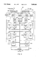
- FIG. 1 diagrammatically illustrates a video teleconferencing system having multiple audiovisual terminals connected to an MCU through a variety of networks.
- FIG. 2 is a block diagram of an MCU configuration.
- FIG. 3 is a block diagram of a Bridge Processing Unit of the MCU configuration of FIG. 2.
- FIG. 4 is a block diagram of a Data Processing Unit of the MCU configuration of FIG. 2.
- FIG. 5 is a schematic block diagram of an embodiment of a VPU.
- FIG. 6 is a block diagram of an MCU configuration illustrating the data flow for continuous presence and rate matching applications.
- FIG. 7 is a block diagram illustrating image tiling in a continuous presence application.
- FIG. 8 is a block diagram illustrating rate matching using the pixel bus arrangement.
- FIG. 9 is a block diagram of an MCU configuration illustrating the data flow for an algorithm matching application.
- FIG. 10 is a block diagram illustrating algorithm matching using the pixel bus arrangement.
- FIG. 11 is a schematic block diagram of a preferred embodiment of the VPU.
- FIG. 12 is a functional block diagram of a Video Compression Processor (VCP).
- VCP Video Compression Processor
- FIG. 13 is a schematic block diagram of a time division multiplex (TDM) bus switch arrangement of the VPU of FIG. 12.
- TDM time division multiplex
- FIG. 14 is an illustration of a selectable region of interest within a pixel area.
- FIG. 15 is a schematic block diagram of the control signal interfaces of the pixel bus controller of the VPU of FIG. 12.
- FIG. 16 is a schematic block diagram of the control logic of the pixel bus controller of FIG. 15.
- FIG. 17 is a schematic block diagram of the VCP output control arrangement.
- FIG. 18 is a timing diagram of the output control signals for the arrangement of FIG. 17.
- FIG. 19 is a flow chart of the output interrupt handler routine.
- FIG. 20 is a schematic block diagram of the VCP input control arrangement.
- FIG. 21 is a timing diagram of the input control signals for the arrangement of FIG. 20.
- FIG. 22 is a flow chart of the input interrupt handler routine for transcoding applications.
- FIG. 23 is a flow chart of the input interrupt handler routine for continuous presence applications.
- FIG. 24 is a flow chart of the main program for codec operation in the VCPs.
- FIG. 25 is a block diagram illustrating reuse of motion compensation information by an encoder.
- a video teleconferencing system is shown in which audiovisual terminals A, B are connected to an MCU 10 through a variety of communications networks 12, each network having a particular type of access interface 14 to the MCU 10, e.g., V.35/RS-449 for private networks, PRI for ISDN networks, and T1 access for switched 56 networks.
- One conference consists of audiovisual terminals A operating at one data rate connected through their respective communications networks to the MCU 10 while another conference comprises audiovisual terminals B operating at another data rate similarly configured.
- FIG. 2 illustrates MCU 10 installed in a host 80386 or 80386-based PC.
- MCU 10 There are four major components in MCU 10: at least one Network Interface Unit (NIU) 20, at least one Bridge Processing Unit (BPU) 22, a Host Processing Unit (HPU) 24, and at least one Video Processing Unit (VPU) 26.
- NIU Network Interface Unit
- BPU Bridge Processing Unit
- HPU Host Processing Unit
- VPU Video Processing Unit
- DPU Data Processing Unit
- Each of these components are digital devices for processing digital data.
- ISA Industry Standard Architecture
- the MCU 10 includes a Network Bus 34 and a BPU Bus 36.
- the Network Bus 34 complies with the Multi-Vendor Integration Protocol (MVIP) while the BPU Bus 36 is a derivative of the MVIP specification.
- MVIP Multi-Vendor Integration Protocol
- BPU Bus 36 is a derivative of the MVIP specification.
- External audiovisual terminals, or codecs 38 connect to the MCU 10 to form conferences
- Each codec 38 typically an H.320 audiovisual terminal, connects to the MCU 10 through a communications network.
- Unsynchronized digital data frames from each codec 38 are made available on the Network bus 34 through NIUs 20.
- the BPUs 22 process the unsynchronized data frames from the Network Bus 34 to produce data frames aligned on an octet boundary which are made available to other BPUs 22 on the BPU bus 36.
- the BPUs 22 also extract audio information from the data frames.
- the audio information is decoded to PCM data and made available on the BPU bus 36 for mixing with audio from other codecs 38 by respective BPUs 22 in a conference.
- the BPUs 22 combine compressed video information and mixed encoded audio information into frames which are placed on the Network Bus 34 for transmission to respective codecs 38.
- the optional DPU 28 performs processing functions similar to the BPUs 22 to support audiovisual terminals having PCS (Intel) codecs.
- the BPUs 22 perform video switching within a conference by selecting video data frames from timeslots on the BPU bus 36 and routing the frames to respective codecs 38 in the conference.
- a particular BPU 22 selects the appropriate video data frames based upon an MCU conference selection process. Typically, the selection process is based upon a comparison of the voice levels of the conference locations. The loudest conference location is designated the current broadcaster to be viewed by all other conference locations while the current broadcaster typically views another location.
- an MCU operator or a particular audiovisual terminal operating in a chair control mode selects a location as the current broadcaster.
- the video data is further processed by the VPUs 26 before it returns through the BPUs.
- the VPUs 26 extract compressed video information from the aligned data frames on the BPU bus 36.
- the compressed video information is decoded and placed on a pixel bus local to each VPU 26.
- the decoded video information on the pixel bus is made available for encoding in the VPU 26 for algorithm transcoding, spatial mixing, and transmission rate matching applications.
- the encoded video information is then placed on the BPU bus 36 for further processing by the BPUs 22 as in the standard conference arrangement.
- the mixed encoded audio may be delayed in memory to compensate for the time spent processing the video information in the VPU 26.
- the MVIP-compliant Network Bus 34 comprises eight full-duplex, serial time-division multiplexed 125 ⁇ s data streams which adhere to the Mitel ST-BUS (Serial Telecom) Generic Device Specification. Each data stream operates at 2 Mbps and is divided into 32 separate timeslots. The total capacity of the bus is therefore 256 timeslots with each timeslot having a capacity of 64 Kbps. In addition to being time-division multiplexed within a data stream, the digital data is space-division multiplexed across the data streams. In this way, a frame of digital data from a communications network can be multiplexed across any of the 256 timeslots for intra-MCU communications.
- the MVIP-derivative BPU bus 36 is a TDM serial bus capable of handling sixteen streams.
- each stream operates at 2 Mbps, and has 32 timeslots,. each timeslot at 64 Kbps for a total of 32 Mbps transfer rate. In another embodiment operating at 4 Mbps, there are 64 timeslots in each stream, for a total of 64 Mbps.
- the HPU 24 provides a management interface to a workstation (not shown) for MCU operations. Through the HPU 24, an operator can control and manage the operation of the other components.
- the HPU 24 controls the setup and establishment of conferences, and performs monitoring and maintenance functions.
- Each NIU 20 connects the MCU 10 with a particular communications network to a particular codec 38 through an appropriate interface port.
- the NIU 20 formats the digital data frames that pass between the MCU 10 and codecs 38 for transmission within the MCU 10 and across the various communications networks. Because the MCU 10 supports many codec connections simultaneously, tariffs usually favor use of multiplexed high-speed interfaces.
- the most common type of NIU 20 supports a single T1 or ISDN primary rate interface over which the network service (e.g., a communications carrier) has time-division-multiplexed a number of individual codec connections.
- the MCU 10 can also include NIUs having interface ports that support only single codec connections.
- the frame structure for the data exchanged between the MCU 10 and the codecs 38 is defined in TSS Rec. H.221.
- Each NIU 20 reformats the digital data frames from the incoming line to an internal MCU format that is independent of the individual codec interfaces to the communications network. The reformatted data is then multiplexed onto the Network Bus channels for transmission to the BPUs 22.
- the TSS H-series recommendations specify that the video data be switched between codecs but do not specify how an MCU performs the switching function.
- the MCU 10 shown in FIG. 2 implements video switching as time and space division multiplexing, instead of analog signal selection switching.
- the BPUs 22 handle video switching within conferences by selecting and routing time and space-division multiplexed digital data.
- Each BPU 22 can support four codecs (audiovisual terminals) and multiple BPUs may be connected through the BPU bus 36. For each codec connection, the BPU 22 demultiplexes the digital data frames from the Network Bus 34, mixes the digital audio data, and multiplexes new digital data frames onto the Network Bus 34 from the mixed digital audio and the appropriate digital video and conferencing data.
- FIG. 3 A detailed block diagram of BPU 22 is illustrated in FIG. 3.
- the BPU 22 is segmented into four partitions (A, B,C,D), each partition having a pair of Digital Signal Processors (DSP) 40, 42 assignable to a particular codec.
- Each BPU partition (A,B,C,D) contains a first DSP (DSP1) 40 and a second DSP (DSP2) 42.
- DSP1 40 transfers and analyzes data to and from the Network Bus 34 and manages a buffer for this data in SRAM memory 46 shared between DSP1 40 and DSP2 42.
- DSP2 42 processes data that has been pre-processed by DSP1 40 and maintains inter-BPU communications over the BPU Bus 36.
- Each BPU 22 also has a DSP that functions as a Control Processor (CP) 44 which maintains a list of partition associations. Because the data streams on the Network Bus 34 and BPU Bus 36 are time and space division multiplexed, the CP 44 operates a Time Division Multiplexer (TDM) having a network switch 48 and a BPU switch 50 to direct selected digital data frames from the data channels to the correct BPU partition.
- TDM Time Division Multiplexer
- the TDM may be implemented by a Mitel MT8980D Digital Switch.
- the CP 44 supports a 32 bit CP bus 47 to the DSPs 40, 42 in the four partitions (A,B,C,D). In addition, the CP 44 supports an 8 bit bus 49 to the network switch 48 and the BPU switch 50.
- the CP 44 interfaces to TDM data streams through serial multiplexer 51.
- BPU configuration information may be stored in EEROM 53.
- the BPU 22 has an HPU interface 41 which allows the HPU 24 (FIG. 2) to perform memory access of a CP SRAM memory 43 and I/O access to control the CP 44.
- Address decode block 45 supports HPU I/O access to the BPU 22 using programmable dip switches selected by system configuration.
- the DPU 28 performs two functions: 1) protocol handling of T.120 stacks for multilayer protocol (MLP) conferencing applications and 2) protocol handling, video bridging and audio processing for PCS (Intel) codec applications.
- MLP is defined in the H-series Recommendations H.200/AV.270 and will not be discussed further.
- Each DPU 28 can support four codecs (audiovisual terminals) and multiple DPUs can be connected through the BPU bus 36, similar to that used for BPUs 22.
- a detailed block diagram of the DPU 28 is illustrated in FIG. 4.
- the DPU 28 is segmented into four partitions (A, B, C, D), each partition having a Digital Signal Processor (DSP) 340 assignable to a particular codec.
- DSPs 340a-d perform the functions of audio decoding, audio mixing, and audio encoding.
- Each DSP 340 has a dedicated memory 346.
- Each DPU 28 also includes a DSP for control and packet processing functions, a packet processor (PKP) 344.
- PDP packet processor
- a system memory 353 is dedicated to the PKP 344.
- the PKP 344 controls a network bus switch 348 and a BPU bus switch 350 to direct selected packets from the network bus 34 and the BPU bus 36 respectively to the correct DPU partition (A, B, C, D).
- the network bus switch 348 may be implemented by two Mitel MT8980 Digital Switches, one switch each for transmit and receive.
- the BPU bus switch 350 may be implemented by Mitel MT8986AP digital switches.
- multiplexers 356 connect the outputs of network bus switch 348 and BPU bus switch 350 to the DSPs 340, the PKP 344, and two HDLC controllers 354 and 355.
- HDLC communication controllers 354 and 355 There are two 32 channel HDLC communication controllers 354 and 355 which have access to data on the network bus 34 through the network bus switch 348.
- the HDLC controllers 354 and 355 may be implemented by Siemens "Munich" PEB20320 devices.
- a packet control memory 343 serves the two HDLC controllers 354 and 355 with control and configuration information.
- the PKP 344 supports a 32 bit bus 347 for controlling and loading the DSPs 340a-d and the HDLC controllers 354, 355. In addition, the PKP 344 supports an 8 bit bus 349 to control the network bus switch 348 and the BPU bus switch 350.
- the DPU 28 has an HPU interface 341 which allows the HPU 24 (FIG. 2) to perform program download to the system memory 353 and I/O access to control the PKP 344 over ISA bus 32.
- Data flow through the DPU 28 will now be described.
- Data packets which have been HDLC encoded by a transmitting audiovisual terminal are received via an NIU 20 and placed onto the network bus 34.
- An HDLC controller 354, 355 receives the data packets from the network bus 34 and removes HDLC framing and stuff bits.
- the HDLC controller 354, 355 then places the packet into the appropriate DSP memory 346a-d via a DMA process.
- the HDLC controllers 354, 355 are programmed by the PKP 344 using configuration information loaded into the packet control memory 343.
- the PKP 344 programs the association of the serial input timeslots received by the HDLC controller 354, 355 to the corresponding DSP memory 346a-d memory location.
- the PKP 344 communicates to the appropriate DSP 340a-d that a new data packet is now in the respective DSP memory 346a-d.
- the DSPs 340 determine whether the packets in memory are audio or video packets.
- Video data is placed directly onto the BPU bus 36.
- Audio data is first decoded to PCM data before being placed onto the BPU bus 36.
- Video data from another video source is received from the BPU bus 36 by a DSP 340 associated with the audiovisual terminal expecting to receive such video data.
- the header for this video data is modified with the appropriate address and time stamp information.
- Audio PCM data streams available on the BPU bus 36 are mixed from one to four sites into a single audio stream and encoded.
- the encoded audio data is placed into the appropriate DSP memory 346a-d with appropriate header information.
- the DSP 340 interrupts the PKP 344 to indicate that a packet is available for transmission.
- the PKP 344 configures the HDLC controller 354, 355 appropriately to take the packet from DSP memory 346 via a DMA process and add HDLC framing and stuff bits.
- the HDLC encoded data packet is then placed into the appropriate timeslot on the network bus 34.
- FIG. 5 is a functional block diagram of VPU 26.
- compressed video information from up to five audiovisual terminals which are in the same conference may be routed to a particular VPU 26 over the BPU bus 36.
- the VPU 26 comprises five video compression processors (VCP0-VCP4), each having a video decoder/encoder pair 102-i, 106-i, and pixel scaling blocks 104-i, 108-i.
- a video decoder and encoder pair 102-i, 106-i is assignable to the compressed video information stream associated with each particular audiovisual terminal in the conference.
- Each video decoder 102-i decodes the compressed video information using the algorithm that matches the encoding algorithm of its associated audiovisual terminal. Included as part of the video decoder 102-i may be the processing to determine the framing, packets, and checksums which may be part of the transmission protocol. It should be noted that a processor encoded video stream could be assigned to multiple audiovisual terminals (e.g., a continuous presence application having more than five audiovisual terminals in the conference).
- a decoder/encoder pair 102-i, 106-i can switch between assignable audiovisual terminals within a conference.
- the decoded video information, or pixels are then scaled up or down (if necessary) by a pixel scaling block 104-i to match the pixel resolution requirements of other audiovisual terminals in the conference that will be encoding the scaled pixels.
- a desktop system may encode at a resolution of 256 ⁇ 240 while an H.320 terminal would require a pixel resolution of 352 ⁇ 288 for a Common Intermediate Format (CIF) image.
- CIF Common Intermediate Format
- the scaled pixels are then made available to any other video encoder 106-j on a shared pixel bus 82.
- Each encoder 106-j is allowed a fixed amount of time (a timeslot) to output pixels onto the pixel bus 82, effectively creating a time division multiplexed bus.
- Each encoder 106-j may sample any of the images available on the pixel bus timeslots for re-encoding and/or spatial mixing.
- Another pixel scaling block 108-j is coupled between the pixel bus 82 and the encoder 106-j for adjusting the pixel resolution of the sampled image as needed.
- decoding decoding
- encoding scaling
- pixel bus sharing in the digital domain provides a particularly flexible and efficient means for algorithm transcoding and transmission rate matching.
- FIG. 6 data from audiovisual terminals 38 arrive over a communications network to respective NIUs 20.
- Five audiovisual terminals 38 (A, B, C, D, E) are connected in the conference and may be, for example, H.320 terminals.
- Audiovisual terminals A and B are shown connected to a particular NIU 20 which supports multiple codec connections (e.g., a T1 interface).
- the other audiovisual terminals C, D, and E connect to NIUs 20 supporting only a single codec connection (e.g. an ISDN interface).
- Each audiovisual terminal 38 places one or more octets of digital data onto the network bus 34 as unsynchronized H.221 framed data.
- the data is unsynchronized since the bit alignment does not necessarily begin on an octet boundary.
- which octet within the 80 octet H.221 frame is not yet known.
- the BPUs 22 determine the H.221 framing, align the octets, and determine the H.221 octet number. This aligned data is made available to all other units on the BPU bus 36.
- the BPUs 22 also extract audio information from the H.221 frames and decode the audio into 16 bit PCM data.
- the decoded audio data is made available on the BPU bus 36 for mixing with audio data from other audiovisual terminals.
- VCPs Video Compression Processors
- the VPU 26 has five VCPs (FIG. 5) which in this example are respectively assigned to the audiovisual terminals 38 (A, B, C, D, E).
- a VCP 60-e on the VPU 26 which is assigned to audiovisual terminal 38 (E) is functionally illustrated in FIG. 7.
- Compressed video information H.261 is extracted from the H.221 frames and decoded by the VCP 60-e as image X.
- the decoder video image X is placed on the pixel bus 82.
- FIG. 7 shows the pixel bus 82 with decoded video frames from each audiovisual terminal 38 (A-E) located in successive timeslots (0-4).
- the VCP 60-e assigned to terminal E receives the decoded video frames from terminals A, B, C and D which are then tiled (spatially mixed) into a single composite image I.
- the tiled image I is then encoded as H.261 video within H.221 framing and placed on the BPU bus 36 (FIG. 6) for BPU processing as described above.
- the data flow through the NIUs 20 and BPUs 22 to the VPU 26 is similar to that of the continuous presence application.
- the audiovisual terminals 38 are, for purposes of this example, H.320 terminals operating at different network data rates.
- terminals A, B and C can be operating at 2B(ISDN) network rates while terminals D and E can be operating at T1 network rates.
- the VPU 26 receives H.221 frames from the BPU bus 36.
- a VCP 60-c extracts and decodes compressed video information (H.261) from the H.221 frames associated with audiovisual terminal 38 (C) at the 2B rate.
- the decoded video image Y is placed on the pixel bus 82.
- VCP 60-d extracts and decodes H.261 video information from H.221 frames associated with audiovisual terminal 38 (D) at the T1 rate.
- the decoded image Z is also placed on the pixel bus 82 in the timeslot assigned to VCP 60-d.
- decoded image Y from terminal C is input from the pixel bus 82 by VCP 60-d and re-encoded as image Y' for transmission at the T1 rate.
- decoded image Z from terminal D is input from pixel bus 82 by VCP 60-c and re-encoded as image Z' at a different rate (2B).
- the rate matching of the present invention whereby the pixel bus makes decoded video frames available to all VCPs for re-encoding at different rates, avoids having to operate different rate terminals at the rate of the lowest rate terminal. This is possible because the video frames on the pixel bus are uncompressed.
- the uncompressed video frames placed on the pixel bus by a VCP associated with a low rate terminal e.g., 2B rate
- a VCP associated with a high rate e.g. T1 terminal.
- Some video frames from the low rate terminal will be repeated on the bus relative to the high rate sampling associated with the high rate terminal.
- uncompressed video frames from the high rate terminal are sampled from the bus by the VCP associated with the low rate terminal. Some video frames from the high rate terminal will be missed relative to the low rate sampling associated with the low rate terminal. However, since the video frames are uncompressed, each terminal still receives an intelligible video signal with an image resolution matching the lower resolution of the source/receiving terminal pair.
- audiovisual terminal 38(A) can be a PCS (Intel) terminal while terminal 38(B) can be an H.320 terminal.
- the H.221 frames from terminal 38(B) flow through the NIU 20 and BPUs 22 to VPU 26, similar to the previously described applications.
- a VCP 60-b extracts and decodes compressed video information (H.261) from H.221 frames associated with audiovisual terminal 38(B) as shown in FIG. 10.
- the decoded image J may possibly be scaled and then is placed on the pixel bus 82 in the assigned timeslot.
- each decoded H.320 image would be scaled from 352 ⁇ 288 (CIF) or 176 ⁇ 144 (QCIF) to match the respective PCS standard image sizes of 320 ⁇ 240 and 160 ⁇ 120.
- CIF 352 ⁇ 288
- QCIF 176 ⁇ 144
- the scaling as both input and output to the pixel bus offers flexibility and would be different for transcoding image J for another conference terminal using a different compression algorithm in the same conference.
- the decoded image J is available to be input by VCP 60-a for re-encoding using the PCS video compression algorithm.
- the encoded image J' has header information added to it to create PCS video packets. Referring again to FIG. 9, these packets are transmitted onto the BPU bus 36 and received by a DPU 28.
- the PCS packets are HDLC encoded by the DPU 28 and transmitted to the Network Bus 34.
- PCM audio information from both terminals (H.320 and PCS) are mixed in the DPU 28, placed into PCS audio packets, HDLC encoded, and placed on the Network Bus 34.
- the NIU 20 sends the PCS packets to terminal 38(A).
- the data flow from audiovisual terminal 38(A) to VPU 26 is different in that PCS packets are routed through DPU 28 instead of the BPU 22.
- the data flow may be such that video frames are switched through only BPUs 22 rather than through DPUs 28, depending on the particular compression algorithm.
- the DPU 28 receives the PCS packets from the Network Bus 34 and removes the HDLC encoding. The DPU 28 then decodes audio packets to PCM data. Finally, the DPU 28 places the PCM data and video packets onto the BPU bus 36.
- a VCP 60-a extracts and decodes PCS compressed video packets associated with terminal 38(A) as shown in FIG. 10.
- the decoded image K is placed on the pixel bus 82 in the assigned timeslot 0.
- the VCP 60-b inputs the image K from pixel bus 82 for re-encoding using the H.261 video compression algorithm.
- the encoded image K' is then framed with the H.221 structure and placed onto BPU bus 36 for routing through BPU 22 and NIU 20 to terminal 38(B).
- the algorithms or terminal types can be other than those shown in the previous example, and that more than two algorithms can be transcoded in a multi-party conference.
- combinations of the three examples described above are possible.
- a continuous presence conference with spatial mixing could be formed between terminals using unlike video compression algorithms at different transmission rates.
- Each tile of the spatially mixed video would have the best available image resolution.
- the VPU 26 includes multiple video compression processor (VCPs) 60 to provide algorithm transcoding and transmission rate matching.
- VCPs video compression processor
- a proprietary 16 bit parallel pixel bus 82 allows for sharing of decoded video frames between VCPs 60.
- the pixel bus 82 allows for spatial mixing in continuous presence applications, or re-encoding of images for video transcoding applications. Operation of the pixel bus 82 will be described below.
- VPU-CP control DSP
- the VPU-CP 62 may be implemented by the Texas Instruments TMS320C31 DSP.
- the VPU-CP 62 has responsibility for control of a TDM bus switch 70, VCP program download, and communication between the HPU 24 and VCPs 60.
- the VPU-CP 62 stores configuration information in serial EEROM 63.
- a CP-Bus 72 is the control processor DSP's (VPU-CP) 62 external memory bus. Most of the control registers, memory and interfaces are memory mapped onto this bus, including VPU-CP SRAM memory 74, TDM bus Switch control and VCP host port registers.
- the VPU-CP 62 is the default owner of the bus.
- the HPU 24 also has access to the entire address range of the control bus through a combination of the ISA shared memory window and a CP-Bus bank register 76.
- ISA Decode and Control Logic 78 on the VPU host interface arbitrates the VPU-CP 62 off the CP-Bus 72 for each HPU access.
- the CP-Bus 72 is split to isolate the higher speed SRAM access activity of the VPU-CP 62 and the slower speed registers and peripherals.
- the VCPs 60 and control registers are thus located on what is called a PKBus 80.
- Each VCP 60 has its own private SRAM program memory 64 and DRAM frame memory 66.
- a CHI serial interface 68 from each VCP connects to the BPU bus 36 via TDM bus switch 70. There may be one to five VCPs populated on a VPU board, depending on the required processing for a given application.
- a communication interface to the VPU 26 is provided by the MVIP derivative TDM serial bus, the BPU bus 36.
- the BPU bus 36 allows the VPU 26 to interface to the BPUs 22, which provide H.221 format Audio/Video/Data to the VPU 26, and to DPUs 28 which provide data conferencing and audio decoding functions.
- the ISA bus 32 is intended primarily for control; data is not typically transferred to the VPU 26 over the ISA bus.
- VPU-CP boot programs are downloaded from the HPU 24 (FIG. 2) via the ISA bus 32. Through the ISA bus 32, the entire 16 Megaword memory space of the CP-Bus 72 can be accessed.
- the HPU interface is an ISA adapter interface.
- the VPU 26 uses both I/O mapped and memory mapped addressing. Interrupt requests from the VPU-CP 62 or the VCPs 60 to the HPU 24 are controlled through IRQ logic 65.
- the VPU 26 includes five identical video compression subsystems, or VCPs 60, which perform video compression, decompression, and pixel mixing.
- VCPs 60 are programmable which enables the VPU 26 to perform various compression algorithms.
- the VCPs 60 are based on the Integrated Information Technologies VCP device. These devices are highly integrated single-chip programmable video codec processors. Each VCP 60 along with external DRAM frame memory 66 and SRAM program memory 64 forms a complete codec. Multiple compression algorithm support is provided through the capability to have algorithm-specific programs downloaded (e.g., H.261, MJPEG and MPEG). Proprietary compression algorithms may also be ported to the VCP devices.
- algorithm-specific programs e.g., H.261, MJPEG and MPEG.
- Proprietary compression algorithms may also be ported to the VCP devices.
- Each VCP 60 is a self-contained codec as shown in FIG. 12. It should be noted that even though the VCPs in the specific embodiment described are configured as full codecs, other embodiments may have VCPs configured as separate encoders and decoders.
- the major functional blocks include a RISC control processor (RISCIIT) 150, a vision processor (VP5) 152, a Huffman codec 154, a H.221/BCH codec 156, and external interfaces.
- the external interfaces include a TDM bus interface 158, an SRAM interface 160, a DRAM interface 162, a host port 164, and a pixel interface 166.
- the programmable RISCIIT 150 maintains the host port 164, TDM interface 158 and pixel interface 166, and controls the H.221/BCH 156, Huffman CODEC 154 and other peripherals internal to the VCP.
- the VP5 152 performs the compression primitives and is controlled by the RISCIIT 150. For detailed information, see the IIT VCP Preliminary Data Sheet and VCP External Reference Specification.
- Program download and control is provided through a host port interface on each VCP 60.
- This host port interface is memory mapped onto the CP-Bus 72, allowing either the VPU-CP 62 or HPU 24 to access the VCPs 60.
- Each VCP 60 is configured with private DRAM memory 66 for video data buffering.
- the SRAM memory 64 is used for RISCIIT program memory and buffering for the serial ports, H.221/261 codec 156, and Huffman CODEC 154.
- the control and program download to the VCPs 60 is through a host port 61 on each VCP processor.
- This port has six registers.
- the term host in this section refers to the VPU-CP 62 (not the HPU) which serves as the host to the VCP processors.
- a list of the host port registers is shown in the following table:
- Each VCP 60 has a TDM port 69 which is connected to the BPU bus 36 through TDM bus switch 70.
- the TDM bus switch 70 may be implemented with Mitel 8986 digital switches.
- the TDM port 69 has a minimum offset between the frame sync pulse and the first bit of (the VCP's) timeslot zero.
- TDM data is aligned with the frame sync pulse, per the MVIP specification.
- the VCP TDM port 69 thus will need an offset line up with the first data bit in a timeslot. This has the effect that the timeslot numbering seen by the VCP is one less (modulo 64) than the timeslot numbering seen by the Mitel switches. For example, the VCP timeslot zero will correspond to the Mitel timeslot one.
- the VCPs 60 and the VPU-CP 62 can connect via serial lines 68 to the BPU bus 36 having bus portions 36a and 36b through the TDM bus switch 70 which allows connection of up to any 32 of the total 512 timeslots on the BPU bus in the case of 2 Mbps operation or 64 of the total 1024 timeslots in the case of 4 Mbps operation.
- a block diagram of the BPU bus 36 and TDM bus switch 70 are shown in FIG. 13.
- the TDM bus switch 70 provides eight stream connections to the BPU bus 36.
- MUXs 71a and 71b connect these eight streams from the TDM bus switch 70 in groups of four to eight of sixteen possible streams on the BPU bus 36 which are shown as bus portions 36a and 36b.
- the MT8986 switches are configured as an eight in by four out crosspoint.
- To implement an eight by eight full duplex crosspoint requires four MT8986 switches: two switches 70a, 70b for transmit data, and two switches 70c, 70d for received data.
- the pixel bus 82 is used to enable multiple VCPs 60 to share decoded pixel data.
- Each VCP 60 in succession has its output control signals driven, causing the particular VCP to output data onto the pixel bus 82.
- the pixel bus controller 84 drives the control signals to the pixel input of each VCP 60 causing the VCP 60 to input data only when programmed. The input data is then available for processing through the processor programming of the video interface DMA controllers internal to the VCP 60.
- the pixel bus 82 connects the pixel outputs of the multiple VCPs 60 to the pixel inputs of the VCPs 60 through a time division multiplexing scheme.
- Each VCP 60 is enabled onto the pixel bus for equal amounts of time.
- the time that each VCP 60 can output is programmed in horizontal and vertical count registers, hcnt and vcnt, which define a fixed rectangle for outputting pixels onto the pixel bus 82.
- the fixed rectangular area is defined by the pixel bus controller 84 and need only be large enough to match the dimensions of the largest image served on the pixel bus 82. For example, the fixed rectangular area may be required to be 600 ⁇ 300 where the number of pixels per line (npix) is 600 and the number of lines (nlines) is 300.
- Each VCP 60 is capable of outputting or receiving pixels from a region of interest within the npix by nlines rectangle as shown in FIG. 14. Since the VCP 60 has control over the size and location of its pixel output within the frame defined by the npix and nlines values, the VCP 60 does not need to "fill" the entire 600 ⁇ 300 image in the previous example.
- the VCP could output within the 600 ⁇ 300 output scan, for example, a CIF (252 ⁇ 288) rectangle R or a QCIF (176 ⁇ 144) rectangle R'.
- Other regions of interest can be defined also, e.g., PCS image sizes (320 ⁇ 240 and 160 ⁇ 120).
- the timing parameters programmed into each VCP 60 must match those programmed into the pixel bus controller 84 hcnt and vcnt registers.
- the VCP pixel interface needs at least 13 pixels of horizontal blanking area and 4 lines of vertical blanking area. Thus, the active pixels output will always be offset from the upper right corner.
- Each VCP 60 will be enabled for nlines lines, each of npix pixels.
- the count programmed into the control registers hcnt and vcnt is constrained to a multiple of four pixels and four lines.
- the formula for the line length and picture height is:
- the VCPs 60 include video input and output sections for receiving and sending pixels from and to the pixel bus 82.
- the pixel bus controller 84 provides control signals to the video input and output sections of the VCPs 60 to enable connection to the pixel bus 82.
- the preferred embodiment of the pixel bus 82 provides five timeslots in which each VCP 60 in succession outputs video pixels. Any of the other VCPs 60 can simultaneously input pixels for compression processing. Each of the timeslots is delimited by the presence of a vertical sync signal. Within the timeslot, horizontal sync signals are programmed to provide horizontal scan intervals to the VCPs 60.
- the pixel bus controller 84 may typically be programmed to provide vertical syncs at a rate which is five times the nominal frame rate, e.g., VSYNC runs at 150 Hz such that all five VCP 60 are active, each at a 30 Hz rate.
- the pixel bus controller 84 which can be implemented with a field programmable gate array (FPGA), has three types of signals: microprocessor interface signals, video input control and video output control signals as shown in the block diagram of FIG. 15.
- the microprocessor control signals allow the VPU-CP 62 to set up the parameters of the pixel bus controller 84.
- the internal hcnt and vcnt registers respectively holding the horizontal length and vertical length may be programmed by selecting the appropriate address enabling the chip select (CS), and pulsing the write strobe (WR).
- the internal registers may be read back by selecting the appropriate address, enabling the chip select (CS), and pulsing the read strobe (OE).
- Video input control signals of the pixel bus controller 84 include the QUALCLK, HSYNC, VSYNC, and ODDCAM [0-4] signals.
- the QUALCLK or pixel clock qualifier signal runs at the pixel rate which is one-half of the 2 X pixel clock inputs to the VCPs 60. This signal is used to gate the 2 X pixel clocks to the VCPs 60, i.e., when this signal is true, the 2 X clock input is valid. This signal is common to all the VCP video input sections and runs continuously.
- the HSYNC, or horizontal sync signal indicates the beginning of a scan line to the VCP video input section. This signal is common among all the VCP video input sections.
- the VSYNC, or vertical sync signal indicates the start of an image scan to the VCP video input sections. This signal is also common among all the VCP video input sections.
- the ODDCAM [0-4], or odd/even indicator signals, are provided individually to each VCP to enable the VCP video input section to only input data from the other VCPs and not from itself.
- the control signals to the video output sections are HSYNC, VSYNC, CLKQUAL [0-4], and BUSENABLE [0-4] signals.
- the HSYNC and VSYNC signals are the same signals as used by the input sections.
- the CLKQUAL [0-4], or pixel clock qualifier signals are individual for each VCP 60 causing each VCP video output section to be active only during its respective pixel bus timeslot.
- tri-state output isolation buffers 67 are used to isolate the VCP video pixel outputs from the pixel bus 82.
- the BUSENABLE signal to the VCP 60 will enable only that VCP onto the pixel bus 82.
- the BUSENABLE signal enables the output of each output isolation buffer 67 onto the pixel bus 82.
- the schematic diagram of the pixel bus controller control logic is shown in FIG. 16. To simplify the diagram, the microprocessor interface signals which are used to load count values are not shown.
- the VCP input and output sections normally operate with a clock input which is two times the pixel rate.
- This clock signal, 2XPIXELCLK is provided both to the VCPs 60 and to the pixel bus controller 84 by an external clock oscillator.
- the 2XPIXELCLK is divided by two by divider block 120 to provide the source for the clock qualifier signals QUALCLK and CLKQUAL [0-4].
- the QUALCLK output of divider block 120 provides the clock source for the horizontal pixel counter HCNT 122.
- HCNT 122 is programmed for the desired line length and counts once for each pixel time.
- the terminal count output (TC) of HCNT 122 provides the horizontal sync signal to all the VCP video input and output sections.
- HSYNC is also used as the clock input to the vertical line counter VCNT 124; thus, the vertical line counter counts once for each complete line of pixels.
- Vertical line counter VCNT 124 is programmed for the desired number of lines and counts once for each scan line.
- the terminal count (TC) of the vertical line counter is used as the vertical sync signal VSYNC to each of the VCP video input and output sections.
- VSYNC also provides the clock input to slot counter 126.
- FIG. 17 is a block diagram which shows the interconnection of output control signals from the pixel bus controller 84 to the VCPs 60.
- FIG. 18 is a timing diagram illustrating the relationship among the control signals. As can be seen from the timing diagram, each of the CLKQUAL [0-4] signals is active only during its respective VCP video output timeslot on the pixel bus 82. When active, these signals run at the pixel rate which is one-half of the 2XPIXELCLK output.
- Each VCP 60 has its video output section programmed to cause an interrupt at the beginning of its active output timeslot, but prior to the active pixel region in that timeslot.
- a flow chart diagram of the video output interrupt handler is shown in FIG. 19.
- the program will next determine if a new buffer of decoded data is available at step 202. If there is new data available, the program will set up the DMA pointers to pull pixel data from the newly decoded data at step 204. If there is not a complete buffer of new decoded data available, the DMA pointer will be set to redisplay the old pixel data at step 206.
- Step 204 indicates that a double buffering scheme is used such that the video decoder is not filling the same buffer which is being displayed.
- FIG. 20 shows the interconnection of input control signals from the pixel bus controller 84 to the VCPs 60.
- the timing diagram indicates the relationship among the video input control signals.
- the video input section of the VCP 60 is programmed to provide an interrupt at the end of each scan.
- the operation of the interrupt handler for transcoding applications is shown in the program flow chart of FIG. 22.
- the ODDCAM signal is checked at 212 to determine if the current timeslot is the particular VCP's timeslot.
- the slot counter is reset to zero at 214 when ODDCAM is zero, indicating that the current timeslot belongs to the VCP. Otherwise, the slot counter is incremented by one at 216.
- the handler checks at 218 to see if there is an empty buffer available. If there is an empty buffer, the handler swaps to the new buffer at step 220.
- the input DMA is then set up to put the pixel data located in the buffer into memory at step 222.
- the slot counter is checked at 224 to determine whether the next timeslot is the desired timeslot to be captured.
- the desired timeslot designation is programmed into the VCP 60.
- the VCP 60 is programmed to perform a selector function to select among the possible input timeslots. If the next timeslot is the desired timeslot, then the DMA is enabled at 226 and will become active on the next vertical sync, capturing the pixel data from the next buffer.
- the video interrupt handler operates similarly except that the input DMA needs to be setup to put pixel data into different regions of memory in order to achieve spatial mixing of the images input during the other VCP timeslots.
- This interrupt handler is shown in the program flow chart of FIG. 23.
- the ODDCAM signal is checked at 232 to determine if the current timeslot is the particular VCP's timeslot.
- the slot counter is reset to zero at 234 when ODDCAM is zero, indicating that the current timeslot is the timeslot of the particular VCP.
- the handler checks at 236 to see if there is an empty buffer available. If there is an empty buffer available, the handler swaps to the new buffer at 238.
- the input DMA is then set up to put buffer contents into memory at 240.
- the slot counter is instead incremented by one at 242.
- the input DMA is also set up to place buffer contents into memory at a region based on the slot counter value at 244.
- the main program task in each VCP 60 runs a video codec loop as shown in the program flow chart of FIG. 24. Flags are used to communicate with the interrupt handler routines (described above) to indicate if a decoded buffer has been generated or if a buffer is ready to be encoded.
- step 252 If there is sufficient compressed video data in the input FIFO at step 250, then decompression begins at step 252. This continues through loop 254 until a complete frame is decoded. When the frame is decoded, a flag is set at 256 to indicate to the output video interrupt handler that the decoded buffer is ready. If there was not sufficient data in the input FIFO, then the encode routine is called at step 258.
- the encode FIFO is checked at 258 to see if there is sufficient room for the encoded video stream. If there is, the captured pixel data buffer is compressed at 260, the encode buffer flag is reset at 262, and then the program flow returns to the beginning of the loop. If there is not sufficient room in the encode compressed data FIFO, then the program goes to the beginning of the loop without encoding a new frame.
- One of the drawbacks of transcoding for conferencing is the deleterious effect on natural conversational flow due to total system delays.
- a significant portion of the encoding time to perform motion compensation based video compression algorithms is due to the motion displacement search. It is desirable to reduce the time necessary for the motion displacement search.
- Motion compensation is a technique used often in video compression algorithms, such as H.261, MPEG, and Indeo. This technique is used to reduce the amount of information needed to represent images in a video sequence, by utilizing the fact that the content of successive frames in a video sequence have significant areas of similar content which may be translated spatially between successive frames. An estimate of the next frame is created using information in the previous frame or frames, along with displacement information.
- each image frame is encoded as blocks of pixels, such as 8 ⁇ 8, 16 ⁇ 16, etc.
- a displacement vector indicates a corresponding block in the previous frame which can be translated spatially to form an estimate of the current block of pixels.
- the displacement information is usually represented as a field of vectors, each having a horizontal and vertical displacement.
- a motion estimation method is used to create the vector field of displacement estimates, based on pixels in the current and previous frame or frames.
- the motion estimation might be implemented using any of the known methods, such as pattern matching, pel recursive, or transform domain techniques.
- a typical motion estimation technique used is pattern matching.
- each block of interest in the current frame is compared to blocks in the previous frame or frames.
- a difference metric of the pixels in the block from the current frame versus the block in the previous frame Is calculated. This is tried over some limited range of displacements (e.g., an area of 15 pixels horizontally by 15 pixels vertically) in the previous frame, and the displacement which had the lowest difference value is used as the displacement estimate.
- the difference metric method might be the sum of absolute values of the differences between pixels, or the sum of the squared differences.
- the block matching search is typically performed over the full image, comparing all of the possible blocks within the displacement range limits.
- motion information received by a decoder as part of a normal decoding operation is passed to an encoder after appropriate filtering and scaling and reordering if necessary.
- motion vectors may, in some cases, be used directly by the encoder, allowing the encoder to skip the motion estimation step, significantly reducing computations.
- the vector fields could be used directly in cases where the block sizes of the decoded image and encoded image are the same, such as a rate matching application for H.320 terminals.
- the motion vector field could also be used as a seed for a further displacement estimate.
- the continued displacement search could then be over a more limited area thus reducing computations.
- the displacement can range over an area of +/-15 pixels.
- the motion vectors from the decoder would need to be processed before being used by the encoder.
- the motion vectors from the decoder would need to be processed before being used by the encoder.
- algorithm H the spatial resolution of 352 ⁇ 288 pixels to another (algorithm I) using 320 ⁇ 240 pixels
- 1.1:1 pixel scaling horizontally and 1.2:1 pixel scaling vertically the vector fields would be scaled (decimated) by the same factors as the pixel images.
- algorithm H uses 16 ⁇ 16 blocks for motion compensation
- algorithm I uses 8 ⁇ 8 blocks for motion compensation
- algorithm H would use a 22 ⁇ 18 entry vector field
- algorithm I would use a 40 ⁇ 36 entry vector field.
- the 22 ⁇ 18 vector field from the decoder would need to be interpolated to 40 ⁇ 36 before being used by the encoder.
- algorithm H might use single pixel accuracy for the displacement estimation, while algorithm I might use half pixel displacement estimates, in which case, the single pixel format would need to be converted to a fractional representation.
- Another example reuses the vector fields from the decoders in a continuous presence application.
- continuous presence multiple images are scaled and tiled into a single image, then re-encoded.
- the vector fields would also be scaled by one half horizontally and vertically, tiled in the same order as the corresponding pixel frames into a single vector field, then reused by the encoder.
- the scaled vector fields might be used directly, or as a seed for further estimation over a reduced search area, significantly reducing computations for the encoder's motion estimation.
- These techniques are applicable to algorithms which might use motion estimation techniques other than block matching, as long as the vector fields are processed to the format used by the encoder.
- FIG. 25 is a block diagram illustrating the reuse of motion compensation information by an encoder.
- a typical motion compensation based video decoder 400 and encoder 410 are shown.
- residual (difference) information is presented to a residual decoder 402 to produce decoded residuals.
- Displacement vectors presented to motion compensation block 404 are used together with a previously decoded frame or frames 406 to determine an estimate of the current frame. This estimated current frame information is combined at 408 with the decoded residuals to form a decompressed image.
- the current frame 412 is a new image frame input into the encoder.
- the current frame 412 and a previous frame or frames 416 are used to make an estimate of the motion displacement between images.
- the displacement information 430 is used by the motion compensation 432 to create an estimate 438 of the current frame, using the decoded previous frame 424.
- the difference (residual) from the current frame and its estimate is calculated at 426 and is encoded by the residual encoder 428 (usually with a lossy method such as discrete cosine transform and quantization).
- the decoded previous frame 424 is calculated by decoding the residual at 436 and summing with the estimated pixels at 434.
- video transcoding between decoder 400 and encoder 410 is improved by making use of the displacement vectors from the decoder in the encoding process.
- displacement vectors are received by the encoder 410 from decoder 400 over a path 409.
- the displacement vectors are passed into the motion estimation block 414 of the encoder 410 to be used either directly or as a seed for a further displacement estimate in the encoding process.
- a pixel scaling block 420 provides pixel scaling between algorithms having different spatial resolutions.
- a motion vector scaling block 422 provides scaling or reformatting of the displacement vectors between algorithms which have unlike pixel block sizes or image formats.
- transcoding described herein is performed in the pixel domain. By performing transcoding in the pixel domain, a wider range of compression algorithms can be accommodated, including algorithms not based on transform techniques. However, the transcoding can also be performed in the transform domain in such cases where the algorithms are transform-based.
- the video decoder 400 and the video encoder 410 can be separate decoder 102-i and encoder 106-j respectively (FIG. 5).
- the decompressed image produced at 408 in FIG. 25 can be placed onto the pixel bus 82 (FIG. 5) to be input and encoded by encoder 410.
- the displacement vectors can be passed from decoder 400 to encoder 410 over a bus such as the PK bus 80 (FIG. 11).
Abstract
Description
______________________________________
Address  Type    Name       Comments
______________________________________
VCP base+0
         R/W     hostdmaport
                            DMA compressed data
                            in/out
VCP base+1
         R/W     hostvcxport
                            Standard VCXI
                            command interface
VCP base+2
         R/W     hostdbgport
                            Debug port
VCP base+3
         R/W     hostctl    Interrupt and DMA
                            control
VCP base+4
         R/W     hostmask   Interrupt mask
VCP base+5
         R       hostirqstat
                            Interrupt status
______________________________________
npix=1028-(hcnt*4)
nlines=516-(vcnt*4)
______________________________________
Frame Rate.sup.1
          2Xpixelclk
(Hz)      clock (MHz)
                     npix    nlines
                                   hcnt  vcnt
______________________________________
30        33.330     372     300   0xA4  0x36
15        33.330     556     400   0x76  0x1D
10        33.330     860     388   0x2A  0x20
7.5       33.330     904     492   0x1F  0x06
30        28.322     368     292.sup.2
                                   0xA5  0x38
15        28.322     372     508   0xA4  0x02
10        28.322     716     396   0x4E  0x1E
7.5       28.322     756     500   0x44  0x04
30        27.000     368     292.sup.3
                                   0xA5  0x38
15        27.000     556     324   0x76  0x30
10        27.000     656     412   0x5D  0x1A
7.5       27.000     892     404   0x22  0x1C
______________________________________
 .sup.1 Nominal Frame Rate given. Desired frame rate is (30000/1001)/n,    n
 1,2,3,4.
 .sup.2 292 is the minimum height due to Sync length requirements. This
 results in a frame rate of 26.3 Hz.
 .sup.3 292 is the minimum height due to Sync length requirements. This
 results in a frame rate of 25.1 Hz.
Claims (31)
Priority Applications (7)
| Application Number | Priority Date | Filing Date | Title |
|---|---|---|---|
| US08/379,274 US5600646A (en) | 1995-01-27 | 1995-01-27 | Video teleconferencing system with digital transcoding |
| DE19681223T DE19681223B4 (en) | 1995-01-27 | 1996-01-16 | Video teleconferencing system with digital transcoding |
| AU46987/96A AU4698796A (en) | 1995-01-27 | 1996-01-16 | Video teleconferencing system with digital transcoding |
| PCT/US1996/000450 WO1996023388A1 (en) | 1995-01-27 | 1996-01-16 | Video teleconferencing system with digital transcoding |
| GB9715337A GB2312807B (en) | 1995-01-27 | 1996-01-16 | Video teleconferencing system with digital transcoding |
| IL11690596A IL116905A (en) | 1995-01-27 | 1996-01-25 | Video teleconferencing system with digital transcoding |
| US10/426,245 US7499416B2 (en) | 1995-01-27 | 2003-04-29 | Video teleconferencing system with digital transcoding |
Applications Claiming Priority (1)
| Application Number | Priority Date | Filing Date | Title |
|---|---|---|---|
| US08/379,274 US5600646A (en) | 1995-01-27 | 1995-01-27 | Video teleconferencing system with digital transcoding |
Related Child Applications (1)
| Application Number | Title | Priority Date | Filing Date |
|---|---|---|---|
| US08/896,554 Continuation US5838664A (en) | 1995-01-27 | 1997-07-17 | Video teleconferencing system with digital transcoding |
Publications (1)
| Publication Number | Publication Date |
|---|---|
| US5600646A true US5600646A (en) | 1997-02-04 |
Family
ID=23496570
Family Applications (1)
| Application Number | Title | Priority Date | Filing Date |
|---|---|---|---|
| US08/379,274 Expired - Lifetime US5600646A (en) | 1995-01-27 | 1995-01-27 | Video teleconferencing system with digital transcoding |
Country Status (6)
| Country | Link |
|---|---|
| US (1) | US5600646A (en) |
| AU (1) | AU4698796A (en) |
| DE (1) | DE19681223B4 (en) |
| GB (1) | GB2312807B (en) |
| IL (1) | IL116905A (en) |
| WO (1) | WO1996023388A1 (en) |
Cited By (101)
| Publication number | Priority date | Publication date | Assignee | Title |
|---|---|---|---|---|
| WO1998057521A1 (en) * | 1997-06-10 | 1998-12-17 | E-Net, Inc. | Interactive video communication over a packet data network |
| US5857189A (en) * | 1996-05-08 | 1999-01-05 | Apple Computer, Inc. | File sharing in a teleconference application |
| US5886734A (en) * | 1997-01-28 | 1999-03-23 | Videoserver, Inc. | Apparatus and method for storage and playback of video images and audio messages in multipoint videoconferencing |
| WO1999029113A1 (en) * | 1997-11-27 | 1999-06-10 | British Telecommunications Public Limited Company | Transcoding |
| WO1999040753A1 (en) * | 1998-02-05 | 1999-08-12 | Fraunhofer-Gesellschaft zur Förderung der angewandten Forschung e.V. | Communication network, method for transmitting a signal, network connecting unit and method for adjusting the bit rate of a scaled data flow |
| US5963547A (en) * | 1996-09-18 | 1999-10-05 | Videoserver, Inc. | Method and apparatus for centralized multipoint conferencing in a packet network |
| US5987009A (en) * | 1995-12-19 | 1999-11-16 | Fujitsu Limited | Multipoint/multichannel connection device in integrated services digital network |
| US5999966A (en) * | 1997-10-07 | 1999-12-07 | Mcdougall; Floyd | Control network-directed video conferencing switching system and method |
| US6058122A (en) * | 1997-08-12 | 2000-05-02 | Electronics And Telecommunications Research Institute | Device for splitting a screen in MPEG image signals at a completely compressed domain and the method thereof |
| US6078362A (en) * | 1997-02-03 | 2000-06-20 | Janima Beheer B.V. | Device for combining video signals which represent images having a different perception depth |
| US6111924A (en) * | 1998-02-03 | 2000-08-29 | Videoserver, Inc. | Error-correction-code synchronization in a videoconferencing gateway |
| US6124881A (en) * | 1997-04-25 | 2000-09-26 | Fujitsu Limited | System for generating composed signals of multiple pictures for use in a video conference system |
| US6163531A (en) * | 1997-10-31 | 2000-12-19 | Intel Corporation | Method and apparatus to throttle connections to a H.323 multipoint controller by receiver terminals in a loosely-coupled conference |
| US6175856B1 (en) * | 1996-09-30 | 2001-01-16 | Apple Computer, Inc. | Method and apparatus for dynamic selection of compression processing during teleconference call initiation |
| US6278691B1 (en) * | 1997-02-17 | 2001-08-21 | Matsushita Electric Industrial Co., Ltd. | Communications system |
| US6285716B1 (en) * | 1994-06-17 | 2001-09-04 | Snell & Wilcox Limited | Video compression |
| US6285661B1 (en) * | 1998-01-28 | 2001-09-04 | Picturetel Corporation | Low delay real time digital video mixing for multipoint video conferencing |
| US6288740B1 (en) | 1998-06-11 | 2001-09-11 | Ezenia! Inc. | Method and apparatus for continuous presence conferencing with voice-activated quadrant selection |
| US6300973B1 (en) | 2000-01-13 | 2001-10-09 | Meir Feder | Method and system for multimedia communication control |
| US6310915B1 (en) * | 1998-11-20 | 2001-10-30 | Harmonic Inc. | Video transcoder with bitstream look ahead for rate control and statistical multiplexing |
| EP1175099A2 (en) * | 2000-07-18 | 2002-01-23 | Pioneer Corporation | Image-coding apparatus and method, data-coding apparatus and method, data-recording apparatus and medium |
| US6343313B1 (en) * | 1996-03-26 | 2002-01-29 | Pixion, Inc. | Computer conferencing system with real-time multipoint, multi-speed, multi-stream scalability |
| US6393059B1 (en) * | 1998-01-22 | 2002-05-21 | Victor Company Of Japan, Ltd. | Conversion of video data bit stream |
| US6397275B1 (en) | 1994-09-07 | 2002-05-28 | Viseon, Inc. | Peripheral video conferencing system |
| US6400763B1 (en) | 1999-02-18 | 2002-06-04 | Hewlett-Packard Company | Compression system which re-uses prior motion vectors |
| US6445699B1 (en) * | 1997-02-25 | 2002-09-03 | Siemens Aktiengesellschaft | Apparatus for processing and generating data using a digital signal processor |
| US20020161910A1 (en) * | 2001-04-30 | 2002-10-31 | David Bill | Generating multiple data streams from a single data source |
| US20030081676A1 (en) * | 2001-10-30 | 2003-05-01 | Industrial Technology Research Institute | Methods and systems for video transcoding in DCT domain with low complexity |
| US6584077B1 (en) | 1996-01-16 | 2003-06-24 | Tandberg Telecom As | Video teleconferencing system with digital transcoding |
| US20030174202A1 (en) * | 2000-01-13 | 2003-09-18 | Noam Eshkoli | Method and system for controlling multimedia video communication |
| US20030210707A1 (en) * | 1998-04-03 | 2003-11-13 | Vertical Networks, Inc. | Systems and methods for multiple mode voice and data communications using intelligenty bridged TDM and packet buses |
| US6650707B2 (en) | 2001-03-02 | 2003-11-18 | Industrial Technology Research Institute | Transcoding apparatus and method |
| US20040001479A1 (en) * | 2002-07-01 | 2004-01-01 | Pounds Gregory E. | Systems and methods for voice and data communications including a network drop and insert interface for an external data routing resource |
| US6697061B1 (en) | 1999-01-21 | 2004-02-24 | Hewlett-Packard Development Company, L.P. | Image compression featuring selective re-use of prior compression data |
| US20040047194A1 (en) * | 2002-04-01 | 2004-03-11 | Macinnis Alexander G. | Memory access engine having multi-level command structure |
| US6711212B1 (en) | 2000-09-22 | 2004-03-23 | Industrial Technology Research Institute | Video transcoder, video transcoding method, and video communication system and method using video transcoding with dynamic sub-window skipping |
| US6731734B1 (en) * | 1999-08-19 | 2004-05-04 | Siemens Information & Communication Networks, Inc. | Apparatus and method for intelligent conference call codec selection |
| US6738356B1 (en) | 2000-08-10 | 2004-05-18 | Convedia Corporation | Object oriented video merging system |
| US20040153510A1 (en) * | 1996-05-08 | 2004-08-05 | Guy Riddle | Accessories providing a telephone conference application one or more capabilities independent of the teleconference application |
| WO2004105394A1 (en) * | 2003-05-23 | 2004-12-02 | Tandberg Telecom As | Method for managing variations in a data flow rate |
| US20040249955A1 (en) * | 2003-06-05 | 2004-12-09 | Randy Wuerful | Method and apparatus for passing call control application information within a network signaling protocol |
| US20040257433A1 (en) * | 2003-06-20 | 2004-12-23 | Lia Tom Erik | Method and apparatus for video conferencing having dynamic picture layout |
| US20050008240A1 (en) * | 2003-05-02 | 2005-01-13 | Ashish Banerji | Stitching of video for continuous presence multipoint video conferencing |
| US6850266B1 (en) * | 1998-06-04 | 2005-02-01 | Roberto Trinca | Process for carrying out videoconferences with the simultaneous insertion of auxiliary information and films with television modalities |
| US20050157164A1 (en) * | 2004-01-20 | 2005-07-21 | Noam Eshkoli | Method and apparatus for mixing compressed video |
| US20050169377A1 (en) * | 2004-02-04 | 2005-08-04 | Chia-Wen Lin | Low-complexity spatial downscaling video transcoder and method thereof |
| US20050207500A1 (en) * | 1999-03-16 | 2005-09-22 | Bober Miroslaw Z | Method and apparatus for motion vector field encoding |
| US20050259144A1 (en) * | 2004-05-21 | 2005-11-24 | Polycom, Inc. | Method and system for preparing video communication image for wide screen display |
| US20060077252A1 (en) * | 2004-10-12 | 2006-04-13 | Bain John R | Method and apparatus for controlling a conference call |
| US20060087553A1 (en) * | 2004-10-15 | 2006-04-27 | Kenoyer Michael L | Video conferencing system transcoder |
| US20060092269A1 (en) * | 2003-10-08 | 2006-05-04 | Cisco Technology, Inc. | Dynamically switched and static multiple video streams for a multimedia conference |
| US20060146124A1 (en) * | 2004-12-17 | 2006-07-06 | Andrew Pepperell | Video conference recorder |
| US20060168637A1 (en) * | 2005-01-25 | 2006-07-27 | Collaboration Properties, Inc. | Multiple-channel codec and transcoder environment for gateway, MCU, broadcast and video storage applications |
| US20060171336A1 (en) * | 2005-01-05 | 2006-08-03 | William Macdonald | Video multi-conference unit (MCU) |
| US20060179110A1 (en) * | 2001-04-30 | 2006-08-10 | Brown Scott K | Duplicating digital streams for digital conferencing using switching technologies |
| US7107383B1 (en) * | 2000-05-03 | 2006-09-12 | Broadcom Corporation | Method and system for multi-channel transfer of data and control information |
| US7113992B1 (en) | 1999-11-08 | 2006-09-26 | Polycom, Inc. | Decomposition architecture for an MCU |
| US20060248210A1 (en) * | 2005-05-02 | 2006-11-02 | Lifesize Communications, Inc. | Controlling video display mode in a video conferencing system |
| US7174365B1 (en) | 2000-11-08 | 2007-02-06 | Polycom Israel Ltd. | System and method for controlling one or more multipoint control units as one multipoint control unit |
| US20070036150A1 (en) * | 1998-04-03 | 2007-02-15 | Pounds Gregory E | Systems and methods for TDM/packet communications using telephony station cards including voltage generators |
| US20070133413A1 (en) * | 2005-12-09 | 2007-06-14 | Andrew Pepperell | Flow control in a video conference |
| US20070156924A1 (en) * | 2006-01-03 | 2007-07-05 | Cisco Technology, Inc. | Method and apparatus for transcoding and transrating in distributed video systems |
| US20070288639A1 (en) * | 2001-04-30 | 2007-12-13 | Aol Llc | Load balancing with direct terminal response |
| US20080049723A1 (en) * | 2001-04-30 | 2008-02-28 | Aol Llc | Generating multiple data streams from a single data source |
| US20080059581A1 (en) * | 2006-09-05 | 2008-03-06 | Andrew Pepperell | Viewing data as part of a video conference |
| US20080068448A1 (en) * | 2006-09-18 | 2008-03-20 | Hansen Robert A | Method for adapting a device to participate in video conference calls |
| US20080100696A1 (en) * | 2006-10-27 | 2008-05-01 | Jochen Christof Schirdewahn | Dynamic Picture Layout for Video Conferencing Based on Properties Derived from Received Conferencing Signals |
| US7379455B2 (en) | 1998-04-03 | 2008-05-27 | Converged Data Solutions Llc | Systems and methods for providing configurable caller ID information |
| US20080158338A1 (en) * | 2006-11-20 | 2008-07-03 | Evans Simon J W | Hardware architecture for video conferencing |
| US20080316298A1 (en) * | 2007-06-22 | 2008-12-25 | King Keith C | Video Decoder which Processes Multiple Video Streams |
| US20090015661A1 (en) * | 2007-07-13 | 2009-01-15 | King Keith C | Virtual Multiway Scaler Compensation |
| US20090059818A1 (en) * | 1998-04-03 | 2009-03-05 | Pickett Scott K | Systems and methods for providing configurable caller id iformation |
| US20090147167A1 (en) * | 2007-10-29 | 2009-06-11 | Park Young-Bae | Nanostructure-Film LCD Devices |
| US7586908B2 (en) | 1998-04-03 | 2009-09-08 | Converged Data Solutions Llc | Systems and methods for multiple mode voice and data communications using intelligenty bridged TDM and packet buses and methods for performing telephony and data functions using the same |
| US7602847B1 (en) * | 2001-03-27 | 2009-10-13 | Vixs Systems, Inc. | Device and method for compression of a video stream |
| US7675972B1 (en) | 2001-07-30 | 2010-03-09 | Vixs Systems, Inc. | System and method for multiple channel video transcoding |
| US20100085419A1 (en) * | 2008-10-02 | 2010-04-08 | Ashish Goyal | Systems and Methods for Selecting Videoconferencing Endpoints for Display in a Composite Video Image |
| US20100110160A1 (en) * | 2008-10-30 | 2010-05-06 | Brandt Matthew K | Videoconferencing Community with Live Images |
| US20100110938A1 (en) * | 2002-06-14 | 2010-05-06 | Polycom, Inc. | Multipoint Multimedia/Audio Conference Using IP Trunking |
| US20100153574A1 (en) * | 2008-12-15 | 2010-06-17 | Microsoft Corporation | Video Conference Rate Matching |
| US20100149301A1 (en) * | 2008-12-15 | 2010-06-17 | Microsoft Corporation | Video Conferencing Subscription Using Multiple Bit Rate Streams |
| US20100157017A1 (en) * | 2008-12-23 | 2010-06-24 | Tandberg Telecom As | Method, device and computer system for processing images in a conference between a plurality of video conferencing terminals |
| US20100185778A1 (en) * | 2001-04-30 | 2010-07-22 | Aol Inc. | Duplicating switch for streaming data units to a terminal |
| EP2214410A2 (en) | 2009-01-30 | 2010-08-04 | Polycom, Inc. | Method and system for conducting continuous presence conferences |
| US20100225736A1 (en) * | 2009-03-04 | 2010-09-09 | King Keith C | Virtual Distributed Multipoint Control Unit |
| US20100225737A1 (en) * | 2009-03-04 | 2010-09-09 | King Keith C | Videoconferencing Endpoint Extension |
| US7869424B2 (en) | 2002-07-01 | 2011-01-11 | Converged Data Solutions Inc. | Systems and methods for voice and data communications including a scalable TDM switch/multiplexer |
| US20110032996A1 (en) * | 2009-08-04 | 2011-02-10 | Polycom, Inc. | Using dual hdvicp coprocessor to accelerate dm6467 h.264 decoder |
| US20110115876A1 (en) * | 2009-11-16 | 2011-05-19 | Gautam Khot | Determining a Videoconference Layout Based on Numbers of Participants |
| US8014597B1 (en) | 2006-03-22 | 2011-09-06 | Woodman Labs | Method for efficient compression and decoding of single sensor color image data |
| US8028092B2 (en) | 2002-06-28 | 2011-09-27 | Aol Inc. | Inserting advertising content |
| US8369967B2 (en) | 1999-02-01 | 2013-02-05 | Hoffberg Steven M | Alarm system controller and a method for controlling an alarm system |
| EP2557780A2 (en) | 2011-08-11 | 2013-02-13 | Polycom, Inc. | Method and system for switching between video streams in a continuous presence conference |
| USRE44306E1 (en) | 1995-02-24 | 2013-06-18 | Apple Inc. | System for terminating multicast channel and data broadcast when at least two second endpoints do not transmit positive acknowledgement message to first endpoint |
| US8532100B2 (en) | 2010-10-19 | 2013-09-10 | Cisco Technology, Inc. | System and method for data exchange in a heterogeneous multiprocessor system |
| EP2693747A2 (en) | 2012-07-30 | 2014-02-05 | Polycom, Inc. | Method and system for conducting video conferences of diverse participating devices |
| US8892495B2 (en) | 1991-12-23 | 2014-11-18 | Blanding Hovenweep, Llc | Adaptive pattern recognition based controller apparatus and method and human-interface therefore |
| US8947492B2 (en) | 2010-06-18 | 2015-02-03 | Microsoft Corporation | Combining multiple bit rate and scalable video coding |
| US9171577B1 (en) | 2003-04-25 | 2015-10-27 | Gopro, Inc. | Encoding and decoding selectively retrievable representations of video content |
| US9386267B1 (en) * | 2012-02-14 | 2016-07-05 | Arris Enterprises, Inc. | Cooperative transcoding to multiple streams |
| US10361802B1 (en) | 1999-02-01 | 2019-07-23 | Blanding Hovenweep, Llc | Adaptive pattern recognition based control system and method |
Families Citing this family (10)
| Publication number | Priority date | Publication date | Assignee | Title |
|---|---|---|---|---|
| US5687095A (en) * | 1994-11-01 | 1997-11-11 | Lucent Technologies Inc. | Video transmission rate matching for multimedia communication systems |
| JPH1051766A (en) | 1996-08-05 | 1998-02-20 | Mitsubishi Electric Corp | Image coding data converter |
| WO1998023075A2 (en) * | 1996-11-22 | 1998-05-28 | Unisys Corporation | Multimedia teleconferencing bridge |
| US6346964B1 (en) | 1996-12-31 | 2002-02-12 | Video Networkcommunications, Inc. | Interoffice broadband communication system using twisted pair telephone wires |
| US6058143A (en) * | 1998-02-20 | 2000-05-02 | Thomson Licensing S.A. | Motion vector extrapolation for transcoding video sequences |
| CN1134936C (en) * | 2001-02-06 | 2004-01-14 | 华为技术有限公司 | Method for implementing video communication service and its information data format |
| FR2831377B1 (en) * | 2001-10-22 | 2004-01-16 | France Telecom | CONFERENCE SYSTEM OF THE TYPE WHICH INCLUDES AN AUDIO AND / OR VIDEO CONFERENCE BRIDGE AND / OR DATA IN WHICH A PLURALITY OF TERMINALS CAN CONNECT TO PARTICIPATE IN A CONFERENCE |
| IL158276A (en) * | 2003-10-02 | 2010-04-29 | Radvision Ltd | Method for dynamically optimizing bandwidth allocation in variable bitrate (multi-rate) conferences |
| GB0623097D0 (en) * | 2006-11-20 | 2006-12-27 | Codian Ltd | Hardware architecture for video conferencing |
| CN110661749A (en) * | 2018-06-28 | 2020-01-07 | 视联动力信息技术股份有限公司 | Video signal processing method and video networking terminal |
Citations (15)
| Publication number | Priority date | Publication date | Assignee | Title |
|---|---|---|---|---|
| US4479195A (en) * | 1982-09-07 | 1984-10-23 | At&T Bell Laboratories | Data conference system |
| US4650929A (en) * | 1984-02-29 | 1987-03-17 | Heinrich-Hertz-Institut Fur Nachrichtentechnik Berlin Gmbh | Communication system for videoconferencing |
| US4748618A (en) * | 1986-05-21 | 1988-05-31 | Bell Communications Research, Inc. | Telecommunications interface |
| US4965819A (en) * | 1988-09-22 | 1990-10-23 | Docu-Vision, Inc. | Video conferencing system for courtroom and other applications |
| US4995071A (en) * | 1988-07-08 | 1991-02-19 | Telenorma Telefonbau Und Normalzeit Gmbh | Video conference installation |
| US5072442A (en) * | 1990-02-28 | 1991-12-10 | Harris Corporation | Multiple clock rate teleconferencing network |
| US5253056A (en) * | 1992-07-02 | 1993-10-12 | At&T Bell Laboratories | Spatial/frequency hybrid video coding facilitating the derivatives of variable-resolution images |
| US5315633A (en) * | 1991-12-20 | 1994-05-24 | Unisys Corporation | Digital video switch for video teleconferencing |
| US5357511A (en) * | 1993-03-22 | 1994-10-18 | Peak Audio, Inc. | Distributed processing in a digital audio mixing network |
| US5382972A (en) * | 1988-09-22 | 1995-01-17 | Kannes; Deno | Video conferencing system for courtroom and other applications |
| US5392284A (en) * | 1990-09-20 | 1995-02-21 | Canon Kabushiki Kaisha | Multi-media communication device |
| US5392223A (en) * | 1992-07-29 | 1995-02-21 | International Business Machines Corp. | Audio/video communications processor |
| US5408274A (en) * | 1993-03-11 | 1995-04-18 | The Regents Of The University Of California | Method and apparatus for compositing compressed video data |
| US5416520A (en) * | 1993-11-30 | 1995-05-16 | Intel Corporation | Multiple encoder output buffer apparatus for differential coding of video information |
| US5446491A (en) * | 1993-12-21 | 1995-08-29 | Hitachi, Ltd. | Multi-point video conference system wherein each terminal comprises a shared frame memory to store information from other terminals |
-
1995
- 1995-01-27 US US08/379,274 patent/US5600646A/en not_active Expired - Lifetime
-
1996
- 1996-01-16 DE DE19681223T patent/DE19681223B4/en not_active Expired - Lifetime
- 1996-01-16 AU AU46987/96A patent/AU4698796A/en not_active Abandoned
- 1996-01-16 WO PCT/US1996/000450 patent/WO1996023388A1/en active Application Filing
- 1996-01-16 GB GB9715337A patent/GB2312807B/en not_active Expired - Lifetime
- 1996-01-25 IL IL11690596A patent/IL116905A/en not_active IP Right Cessation
Patent Citations (15)
| Publication number | Priority date | Publication date | Assignee | Title |
|---|---|---|---|---|
| US4479195A (en) * | 1982-09-07 | 1984-10-23 | At&T Bell Laboratories | Data conference system |
| US4650929A (en) * | 1984-02-29 | 1987-03-17 | Heinrich-Hertz-Institut Fur Nachrichtentechnik Berlin Gmbh | Communication system for videoconferencing |
| US4748618A (en) * | 1986-05-21 | 1988-05-31 | Bell Communications Research, Inc. | Telecommunications interface |
| US4995071A (en) * | 1988-07-08 | 1991-02-19 | Telenorma Telefonbau Und Normalzeit Gmbh | Video conference installation |
| US5382972A (en) * | 1988-09-22 | 1995-01-17 | Kannes; Deno | Video conferencing system for courtroom and other applications |
| US4965819A (en) * | 1988-09-22 | 1990-10-23 | Docu-Vision, Inc. | Video conferencing system for courtroom and other applications |
| US5072442A (en) * | 1990-02-28 | 1991-12-10 | Harris Corporation | Multiple clock rate teleconferencing network |
| US5392284A (en) * | 1990-09-20 | 1995-02-21 | Canon Kabushiki Kaisha | Multi-media communication device |
| US5315633A (en) * | 1991-12-20 | 1994-05-24 | Unisys Corporation | Digital video switch for video teleconferencing |
| US5253056A (en) * | 1992-07-02 | 1993-10-12 | At&T Bell Laboratories | Spatial/frequency hybrid video coding facilitating the derivatives of variable-resolution images |
| US5392223A (en) * | 1992-07-29 | 1995-02-21 | International Business Machines Corp. | Audio/video communications processor |
| US5408274A (en) * | 1993-03-11 | 1995-04-18 | The Regents Of The University Of California | Method and apparatus for compositing compressed video data |
| US5357511A (en) * | 1993-03-22 | 1994-10-18 | Peak Audio, Inc. | Distributed processing in a digital audio mixing network |
| US5416520A (en) * | 1993-11-30 | 1995-05-16 | Intel Corporation | Multiple encoder output buffer apparatus for differential coding of video information |
| US5446491A (en) * | 1993-12-21 | 1995-08-29 | Hitachi, Ltd. | Multi-point video conference system wherein each terminal comprises a shared frame memory to store information from other terminals |
Non-Patent Citations (13)
| Title |
|---|
| "Video Codec Chip Set Provides MPEG, p*64, and JPEG Compliance," Electrical Design News, vol. 37, No. 9, pp. 103-104 (Apr. 23, 1992). |
| Botzko, S., Continuous Presence for H.320 Multipoint Conferences, Contribution to T1A1.5 Committee (Nov. 4, 1993). * |
| Chen, T. C., et al., "Continuous Presence Video Bridging Based on H.261 Standard," SPIE vol. 2094, pp. 269-280, Visual Comm. and Image Processing '93, (Nov. 8-11, 1993). |
| Chen, T. C., et al., Continuous Presence Video Bridging Based on H.261 Standard, SPIE vol. 2094, pp. 269 280, Visual Comm. and Image Processing 93, (Nov. 8 11, 1993). * |
| Gharavi, H. and Partovi, M. H., "Video Coding and Distribution Over ATM for Multipoint Teleconferencing," IEEE, pp. 1-7 (Nov. 29, 1993). |
| Gharavi, H. and Partovi, M. H., Video Coding and Distribution Over ATM for Multipoint Teleconferencing, IEEE, pp. 1 7 (Nov. 29, 1993). * |
| Horn, D. N. et al., "A Standards-Based Multimedia Conferencing Bridge," AT& T Technical Journal, pp. 41-49 (Jan./Feb. 1993). |
| Horn, D. N. et al., A Standards Based Multimedia Conferencing Bridge, AT & T Technical Journal, pp. 41 49 (Jan./Feb. 1993). * |
| Krause, R., Indeo, H.320 Silicon Pursued, Electronic News, vol. 40, No. 2023, (Jul. 18, 1994). * |
| Morrison, D. G., et al., "Reduction of the Bit-Rate of Compressed Video While in its Coded Form," Sixth International Workshop on Packet Video, U.S.A., (1994, Sep.). |
| Morrison, D. G., et al., Reduction of the Bit Rate of Compressed Video While in its Coded Form, Sixth International Workshop on Packet Video, U.S.A., (1994, Sep.). * |
| Morrison, D. G., Low delay Video Transcoder for Multimedia Interworking, First International Workshop on Mobile Multimedia Communications, Tokyo, (1993, Dec.). * |
| Video Codec Chip Set Provides MPEG, p*64, and JPEG Compliance, Electrical Design News, vol. 37, No. 9, pp. 103 104 (Apr. 23, 1992). * |
Cited By (257)
| Publication number | Priority date | Publication date | Assignee | Title |
|---|---|---|---|---|
| US8892495B2 (en) | 1991-12-23 | 2014-11-18 | Blanding Hovenweep, Llc | Adaptive pattern recognition based controller apparatus and method and human-interface therefore |
| US6625221B2 (en) * | 1994-06-17 | 2003-09-23 | Snell & Wilcox Limited | Video compression |
| US6285716B1 (en) * | 1994-06-17 | 2001-09-04 | Snell & Wilcox Limited | Video compression |
| US6397275B1 (en) | 1994-09-07 | 2002-05-28 | Viseon, Inc. | Peripheral video conferencing system |
| US6654825B2 (en) | 1994-09-07 | 2003-11-25 | Rsi Systems, Inc. | Peripheral video conferencing system with control unit for adjusting the transmission bandwidth of the communication channel |
| US6519662B2 (en) | 1994-09-07 | 2003-02-11 | Rsi Systems, Inc. | Peripheral video conferencing system |
| US7499416B2 (en) | 1995-01-27 | 2009-03-03 | Tandberg Telecom As | Video teleconferencing system with digital transcoding |
| US20030231600A1 (en) * | 1995-01-27 | 2003-12-18 | Tandberg Telecom As | Video teleconferencing system with digital transcoding |
| USRE44395E1 (en) | 1995-02-24 | 2013-07-23 | Apple Inc. | System for terminating multicast channel and data broadcast when at least two second endpoints do not transmit positive acknowledgement message to first endpoint |
| USRE44306E1 (en) | 1995-02-24 | 2013-06-18 | Apple Inc. | System for terminating multicast channel and data broadcast when at least two second endpoints do not transmit positive acknowledgement message to first endpoint |
| US5987009A (en) * | 1995-12-19 | 1999-11-16 | Fujitsu Limited | Multipoint/multichannel connection device in integrated services digital network |
| US6501738B1 (en) | 1995-12-19 | 2002-12-31 | Fujitsu Limited | Multipoint/multichannel connection device in integrated services digital network |
| US6584077B1 (en) | 1996-01-16 | 2003-06-24 | Tandberg Telecom As | Video teleconferencing system with digital transcoding |
| US7934002B2 (en) | 1996-03-26 | 2011-04-26 | Pixion, Inc. | Presenter client operations |
| US7813304B2 (en) | 1996-03-26 | 2010-10-12 | Pixion, Inc. | Providing conferencing data in a network communications system based on client capabilities |
| US7426191B2 (en) | 1996-03-26 | 2008-09-16 | Pixion, Inc. | Providing conference data in a network communications system based on client or server information examined during a conference |
| US8682972B2 (en) | 1996-03-26 | 2014-03-25 | Pixion, Inc. | Presenting information in a conference |
| US20050169197A1 (en) * | 1996-03-26 | 2005-08-04 | Pixion, Inc. | Real-time, multi-point, multi-speed, multi-stream scalable computer network communications system |
| US8965975B2 (en) | 1996-03-26 | 2015-02-24 | Pixion, Inc. | Presenting information in a conference |
| US20050163062A1 (en) * | 1996-03-26 | 2005-07-28 | Pixion, Inc. | Real-time, multi-point, multi-speed, multi-stream scalable computer network communications system |
| US20100306674A1 (en) * | 1996-03-26 | 2010-12-02 | Joseph Salesky | Presenting Information in a Conference |
| US20070083597A1 (en) * | 1996-03-26 | 2007-04-12 | Pixion, Inc. | Presenting images in a conference system |
| US7836163B2 (en) | 1996-03-26 | 2010-11-16 | Pixion, Inc. | Management of stored conference data |
| US6343313B1 (en) * | 1996-03-26 | 2002-01-29 | Pixion, Inc. | Computer conferencing system with real-time multipoint, multi-speed, multi-stream scalability |
| US7197535B2 (en) | 1996-03-26 | 2007-03-27 | Pixion, Inc. | System and method for frame image capture |
| US7310675B2 (en) | 1996-03-26 | 2007-12-18 | Pixion, Inc. | Providing data updates in a network communications system based on connection or load parameters |
| US20080215680A1 (en) * | 1996-03-26 | 2008-09-04 | Joseph Salesky | Conference Server Operations |
| US7822859B2 (en) | 1996-03-26 | 2010-10-26 | Pixion, Inc. | Conference server redundancy |
| US20050080850A1 (en) * | 1996-03-26 | 2005-04-14 | Pixion, Inc. | Real-time, multi-point, multi-speed, multi-stream scalable computer network communications system |
| US7418476B2 (en) | 1996-03-26 | 2008-08-26 | Pixion, Inc. | Presenting images in a conference system |
| US7627663B2 (en) | 1996-03-26 | 2009-12-01 | Pixion, Inc. | Client classification and management |
| US7877489B2 (en) | 1996-03-26 | 2011-01-25 | Pixion, Inc. | Negotiation and validation of a client in a video conference |
| US20080195955A1 (en) * | 1996-03-26 | 2008-08-14 | Joseph Salesky | Load Reduction and Scalability |
| US9049272B2 (en) | 1996-03-26 | 2015-06-02 | Pixion, Inc. | Presenting information in a conference |
| US9077776B1 (en) | 1996-03-26 | 2015-07-07 | Pixion, Inc. | Presenting information in a conference |
| US7369515B2 (en) | 1996-03-26 | 2008-05-06 | Pixion, Inc. | Providing conferencing data in a network communications system based on client capabilities |
| US20080195704A1 (en) * | 1996-03-26 | 2008-08-14 | Joseph Salesky | Management of Stored Conference Data |
| US20080195703A1 (en) * | 1996-03-26 | 2008-08-14 | Joseph Salesky | Negotiation and Validation of a Client in a Video Conference |
| US20080183807A1 (en) * | 1996-03-26 | 2008-07-31 | Pixion, Inc. | Providing conference data in a network communications system based on client or server information examined during a conference |
| US20080183808A1 (en) * | 1996-03-26 | 2008-07-31 | Pixion, Inc. | Providing conferencing data in a network communications system based on client capabilities |
| US9558235B1 (en) | 1996-03-26 | 2017-01-31 | Pixion, Inc. | Storage and management of conference data |
| US7593987B2 (en) | 1996-03-26 | 2009-09-22 | Pixion, Inc. | Load reduction and scalability |
| US20080133661A1 (en) * | 1996-03-26 | 2008-06-05 | Joseph Salesky | Client Classification and Management |
| US7715331B2 (en) | 1996-03-26 | 2010-05-11 | Pixion, Inc. | Providing conference data in a network communications system based on client or server information examined during a conference |
| US20080133769A1 (en) * | 1996-03-26 | 2008-06-05 | Joseph Salesky | Conference Server Redundancy |
| US7716344B2 (en) | 1996-03-26 | 2010-05-11 | Pixion, Inc. | Conference server operations |
| US20080133660A1 (en) * | 1996-03-26 | 2008-06-05 | Joseph Salesky | Presenter Client Operations |
| US20040080504A1 (en) * | 1996-03-26 | 2004-04-29 | Pixion, Inc. | Real-time, multi-point, multi-speed, multi-stream scalable computer network communications system |
| US7167897B2 (en) * | 1996-05-08 | 2007-01-23 | Apple Computer, Inc. | Accessories providing a telephone conference application one or more capabilities independent of the teleconference application |
| US20070162589A1 (en) * | 1996-05-08 | 2007-07-12 | Guy Riddle | File sharing using instant messaging applications |
| US20040153510A1 (en) * | 1996-05-08 | 2004-08-05 | Guy Riddle | Accessories providing a telephone conference application one or more capabilities independent of the teleconference application |
| US5857189A (en) * | 1996-05-08 | 1999-01-05 | Apple Computer, Inc. | File sharing in a teleconference application |
| US7529796B2 (en) | 1996-05-08 | 2009-05-05 | Apple Inc. | File sharing using near real time messaging |
| US20060271628A1 (en) * | 1996-05-08 | 2006-11-30 | Guy Riddle | Accessories for teleconference component |
| US7392286B2 (en) | 1996-05-08 | 2008-06-24 | Apple Inc. | Accessories for teleconference component |
| US7437420B2 (en) | 1996-05-08 | 2008-10-14 | Apple Inc. | Accessories providing a telephone conference application one or more capabilities independent of the teleconference application |
| US5963547A (en) * | 1996-09-18 | 1999-10-05 | Videoserver, Inc. | Method and apparatus for centralized multipoint conferencing in a packet network |
| US6404745B1 (en) | 1996-09-18 | 2002-06-11 | Ezenia! Inc. | Method and apparatus for centralized multipoint conferencing in a packet network |
| US6175856B1 (en) * | 1996-09-30 | 2001-01-16 | Apple Computer, Inc. | Method and apparatus for dynamic selection of compression processing during teleconference call initiation |
| US5990933A (en) * | 1997-01-28 | 1999-11-23 | Videoserver, Inc. | Apparatus and method for storage and playback of video images and audio messages in multipoint videoconferencing |
| US5886734A (en) * | 1997-01-28 | 1999-03-23 | Videoserver, Inc. | Apparatus and method for storage and playback of video images and audio messages in multipoint videoconferencing |
| US6078362A (en) * | 1997-02-03 | 2000-06-20 | Janima Beheer B.V. | Device for combining video signals which represent images having a different perception depth |
| US6278691B1 (en) * | 1997-02-17 | 2001-08-21 | Matsushita Electric Industrial Co., Ltd. | Communications system |
| US6445699B1 (en) * | 1997-02-25 | 2002-09-03 | Siemens Aktiengesellschaft | Apparatus for processing and generating data using a digital signal processor |
| US6124881A (en) * | 1997-04-25 | 2000-09-26 | Fujitsu Limited | System for generating composed signals of multiple pictures for use in a video conference system |
| US5923655A (en) * | 1997-06-10 | 1999-07-13 | E--Net, Inc. | Interactive video communication over a packet data network |
| WO1998057521A1 (en) * | 1997-06-10 | 1998-12-17 | E-Net, Inc. | Interactive video communication over a packet data network |
| US6058122A (en) * | 1997-08-12 | 2000-05-02 | Electronics And Telecommunications Research Institute | Device for splitting a screen in MPEG image signals at a completely compressed domain and the method thereof |
| US5999966A (en) * | 1997-10-07 | 1999-12-07 | Mcdougall; Floyd | Control network-directed video conferencing switching system and method |
| US6163531A (en) * | 1997-10-31 | 2000-12-19 | Intel Corporation | Method and apparatus to throttle connections to a H.323 multipoint controller by receiver terminals in a loosely-coupled conference |
| AU744535B2 (en) * | 1997-11-27 | 2002-02-28 | British Telecommunications Public Limited Company | Transcoding |
| WO1999029113A1 (en) * | 1997-11-27 | 1999-06-10 | British Telecommunications Public Limited Company | Transcoding |
| US6625320B1 (en) | 1997-11-27 | 2003-09-23 | British Telecommunications Public Limited Company | Transcoding |
| US6393059B1 (en) * | 1998-01-22 | 2002-05-21 | Victor Company Of Japan, Ltd. | Conversion of video data bit stream |
| US6285661B1 (en) * | 1998-01-28 | 2001-09-04 | Picturetel Corporation | Low delay real time digital video mixing for multipoint video conferencing |
| US6111924A (en) * | 1998-02-03 | 2000-08-29 | Videoserver, Inc. | Error-correction-code synchronization in a videoconferencing gateway |
| WO1999040753A1 (en) * | 1998-02-05 | 1999-08-12 | Fraunhofer-Gesellschaft zur Förderung der angewandten Forschung e.V. | Communication network, method for transmitting a signal, network connecting unit and method for adjusting the bit rate of a scaled data flow |
| US6853650B1 (en) | 1998-02-05 | 2005-02-08 | Fraunhofer-Gesellschaft Zur Foerderung Der Angewandten Forschung E.V. | Communication network, method for transmitting a signal, network connecting unit and method for adjusting the bit rate of a scaled data flow |
| US8644303B2 (en) | 1998-04-03 | 2014-02-04 | Rpx Corporation | Systems and methods for multiple mode voice and data communications using intelligently bridged TDM and packet buses |
| US20090059818A1 (en) * | 1998-04-03 | 2009-03-05 | Pickett Scott K | Systems and methods for providing configurable caller id iformation |
| US7379455B2 (en) | 1998-04-03 | 2008-05-27 | Converged Data Solutions Llc | Systems and methods for providing configurable caller ID information |
| US20030210707A1 (en) * | 1998-04-03 | 2003-11-13 | Vertical Networks, Inc. | Systems and methods for multiple mode voice and data communications using intelligenty bridged TDM and packet buses |
| US8144729B2 (en) | 1998-04-03 | 2012-03-27 | Converged Data Solutions, Inc. | Systems and methods for multiple mode voice and data communications using intelligently bridged TDM and packet buses |
| US20100208727A1 (en) * | 1998-04-03 | 2010-08-19 | Pounds Gregory E | Systems and methods for generating power in a communications system |
| US7626981B2 (en) | 1998-04-03 | 2009-12-01 | Converged Data Solutions Llc | Systems and methods for TDM/packet communications using telephony station cards including voltage generators |
| US7586908B2 (en) | 1998-04-03 | 2009-09-08 | Converged Data Solutions Llc | Systems and methods for multiple mode voice and data communications using intelligenty bridged TDM and packet buses and methods for performing telephony and data functions using the same |
| US8675671B2 (en) | 1998-04-03 | 2014-03-18 | Rpx Corporation | Systems and methods for multiple mode voice and data communications using intelligently bridged TDM and packet buses and methods for performing telephony and data functions using the same |
| US8588213B2 (en) | 1998-04-03 | 2013-11-19 | Rpx Corporation | Systems and methods for generating power in a communications system |
| US20070036150A1 (en) * | 1998-04-03 | 2007-02-15 | Pounds Gregory E | Systems and methods for TDM/packet communications using telephony station cards including voltage generators |
| US7310308B2 (en) | 1998-04-03 | 2007-12-18 | Converged Data Solutions Llc | Systems and methods for multiple mode voice and data communications using intelligently bridged TDM and packet buses |
| US8184624B2 (en) | 1998-04-03 | 2012-05-22 | Converged Data Solutions Inc. | Systems and methods for multiple mode voice and data communications using intelligently bridged TDM and packet buses and methods for performing telephony and data functions using the same |
| US6850266B1 (en) * | 1998-06-04 | 2005-02-01 | Roberto Trinca | Process for carrying out videoconferences with the simultaneous insertion of auxiliary information and films with television modalities |
| US6288740B1 (en) | 1998-06-11 | 2001-09-11 | Ezenia! Inc. | Method and apparatus for continuous presence conferencing with voice-activated quadrant selection |
| US6310915B1 (en) * | 1998-11-20 | 2001-10-30 | Harmonic Inc. | Video transcoder with bitstream look ahead for rate control and statistical multiplexing |
| US6697061B1 (en) | 1999-01-21 | 2004-02-24 | Hewlett-Packard Development Company, L.P. | Image compression featuring selective re-use of prior compression data |
| US10361802B1 (en) | 1999-02-01 | 2019-07-23 | Blanding Hovenweep, Llc | Adaptive pattern recognition based control system and method |
| US8583263B2 (en) | 1999-02-01 | 2013-11-12 | Steven M. Hoffberg | Internet appliance system and method |
| US9535563B2 (en) | 1999-02-01 | 2017-01-03 | Blanding Hovenweep, Llc | Internet appliance system and method |
| US8369967B2 (en) | 1999-02-01 | 2013-02-05 | Hoffberg Steven M | Alarm system controller and a method for controlling an alarm system |
| US6400763B1 (en) | 1999-02-18 | 2002-06-04 | Hewlett-Packard Company | Compression system which re-uses prior motion vectors |
| US7724826B2 (en) * | 1999-03-16 | 2010-05-25 | Mitsubishi Denki Kabushiki Kaisha | Method and apparatus for motion vector field encoding |
| US20050207500A1 (en) * | 1999-03-16 | 2005-09-22 | Bober Miroslaw Z | Method and apparatus for motion vector field encoding |
| US6731734B1 (en) * | 1999-08-19 | 2004-05-04 | Siemens Information & Communication Networks, Inc. | Apparatus and method for intelligent conference call codec selection |
| US20070126862A1 (en) * | 1999-11-08 | 2007-06-07 | Polycom Israel Ltd. | System and method for controlling one or more multipoint control units as one multipoint control unit |
| US8843550B2 (en) | 1999-11-08 | 2014-09-23 | Polycom Israel Ltd. | System and method for controlling one or more multipoint control units as one multipoint control unit |
| US7113992B1 (en) | 1999-11-08 | 2006-09-26 | Polycom, Inc. | Decomposition architecture for an MCU |
| US7542068B2 (en) | 2000-01-13 | 2009-06-02 | Polycom, Inc. | Method and system for controlling multimedia video communication |
| US6496216B2 (en) | 2000-01-13 | 2002-12-17 | Polycom Israel Ltd. | Method and system for multimedia communication control |
| US20030174202A1 (en) * | 2000-01-13 | 2003-09-18 | Noam Eshkoli | Method and system for controlling multimedia video communication |
| US6757005B1 (en) | 2000-01-13 | 2004-06-29 | Polycom Israel, Ltd. | Method and system for multimedia video processing |
| US6300973B1 (en) | 2000-01-13 | 2001-10-09 | Meir Feder | Method and system for multimedia communication control |
| US7107383B1 (en) * | 2000-05-03 | 2006-09-12 | Broadcom Corporation | Method and system for multi-channel transfer of data and control information |
| US7334074B2 (en) | 2000-05-03 | 2008-02-19 | Broadcom Corporation | Method and system for multi-channel transfer of data and control |
| US20070016713A1 (en) * | 2000-05-03 | 2007-01-18 | Sundar Rajan | Method and system for multi-channel transfer of data and control |
| EP1175099A2 (en) * | 2000-07-18 | 2002-01-23 | Pioneer Corporation | Image-coding apparatus and method, data-coding apparatus and method, data-recording apparatus and medium |
| EP1175099A3 (en) * | 2000-07-18 | 2006-08-09 | Pioneer Corporation | Image-coding apparatus and method, data-coding apparatus and method, data-recording apparatus and medium |
| US6738356B1 (en) | 2000-08-10 | 2004-05-18 | Convedia Corporation | Object oriented video merging system |
| US6711212B1 (en) | 2000-09-22 | 2004-03-23 | Industrial Technology Research Institute | Video transcoder, video transcoding method, and video communication system and method using video transcoding with dynamic sub-window skipping |
| US7174365B1 (en) | 2000-11-08 | 2007-02-06 | Polycom Israel Ltd. | System and method for controlling one or more multipoint control units as one multipoint control unit |
| US6650707B2 (en) | 2001-03-02 | 2003-11-18 | Industrial Technology Research Institute | Transcoding apparatus and method |
| US7602847B1 (en) * | 2001-03-27 | 2009-10-13 | Vixs Systems, Inc. | Device and method for compression of a video stream |
| US20110211495A1 (en) * | 2001-04-30 | 2011-09-01 | Brown Scott K | Duplicating digital streams for digital conferencing using switching technologies |
| US7991911B2 (en) | 2001-04-30 | 2011-08-02 | Aol Inc. | Duplicating switch for streaming data units to a terminal using different communication protocols |
| US8463853B2 (en) | 2001-04-30 | 2013-06-11 | Facebook, Inc. | Duplicating digital streams for digital conferencing using switching technologies |
| US8572278B2 (en) | 2001-04-30 | 2013-10-29 | Facebook, Inc. | Generating multiple data streams from a single data source |
| US8843559B2 (en) | 2001-04-30 | 2014-09-23 | Facebook, Inc. | Modifying payloads of digital streams for digital conferencing |
| US7266609B2 (en) | 2001-04-30 | 2007-09-04 | Aol Llc | Generating multiple data streams from a single data source |
| US20060179110A1 (en) * | 2001-04-30 | 2006-08-10 | Brown Scott K | Duplicating digital streams for digital conferencing using switching technologies |
| US9521006B2 (en) | 2001-04-30 | 2016-12-13 | Facebook, Inc. | Duplicating digital streams for digital conferencing using switching technologies |
| US20100185778A1 (en) * | 2001-04-30 | 2010-07-22 | Aol Inc. | Duplicating switch for streaming data units to a terminal |
| US9537667B2 (en) | 2001-04-30 | 2017-01-03 | Facebook, Inc. | Duplicating digital streams for digital conferencing using switching technologies |
| US20070288639A1 (en) * | 2001-04-30 | 2007-12-13 | Aol Llc | Load balancing with direct terminal response |
| US7124166B2 (en) * | 2001-04-30 | 2006-10-17 | Aol Llc | Duplicating digital streams for digital conferencing using switching technologies |
| US8904026B2 (en) | 2001-04-30 | 2014-12-02 | Facebook, Inc. | Time-shifting streaming data |
| US20020161910A1 (en) * | 2001-04-30 | 2002-10-31 | David Bill | Generating multiple data streams from a single data source |
| US7921157B2 (en) | 2001-04-30 | 2011-04-05 | Aol Inc. | Duplicating digital streams for digital conferencing using switching technologies |
| US8130755B2 (en) | 2001-04-30 | 2012-03-06 | Aol Inc. | Load balancing with direct terminal response |
| US8224991B2 (en) | 2001-04-30 | 2012-07-17 | Aol Inc. | Duplicating switch for streaming data units to a terminal using different communication protocols |
| US9049032B2 (en) | 2001-04-30 | 2015-06-02 | Facebook, Inc. | Prioritizing digital streams during digital conferencing |
| US20080049723A1 (en) * | 2001-04-30 | 2008-02-28 | Aol Llc | Generating multiple data streams from a single data source |
| US7675972B1 (en) | 2001-07-30 | 2010-03-09 | Vixs Systems, Inc. | System and method for multiple channel video transcoding |
| US20030081676A1 (en) * | 2001-10-30 | 2003-05-01 | Industrial Technology Research Institute | Methods and systems for video transcoding in DCT domain with low complexity |
| US7236529B2 (en) | 2001-10-30 | 2007-06-26 | Industrial Technology Research Institute | Methods and systems for video transcoding in DCT domain with low complexity |
| US20040047194A1 (en) * | 2002-04-01 | 2004-03-11 | Macinnis Alexander G. | Memory access engine having multi-level command structure |
| US7565462B2 (en) | 2002-04-01 | 2009-07-21 | Broadcom Corporation | Memory access engine having multi-level command structure |
| US20090282172A1 (en) * | 2002-04-01 | 2009-11-12 | Macinnis Alexander G | Memory access engine having multi-level command structure |
| US20080133786A1 (en) * | 2002-04-01 | 2008-06-05 | Macinnis Alexander G | Memory access engine having multi-level command structure |
| US7302503B2 (en) * | 2002-04-01 | 2007-11-27 | Broadcom Corporation | Memory access engine having multi-level command structure |
| US20100110938A1 (en) * | 2002-06-14 | 2010-05-06 | Polycom, Inc. | Multipoint Multimedia/Audio Conference Using IP Trunking |
| US8000319B2 (en) | 2002-06-14 | 2011-08-16 | Polycom, Inc. | Multipoint multimedia/audio conference using IP trunking |
| US8028092B2 (en) | 2002-06-28 | 2011-09-27 | Aol Inc. | Inserting advertising content |
| US8769151B2 (en) | 2002-06-28 | 2014-07-01 | Facebook, Inc. | Adding advertising content to media content |
| US8762575B2 (en) | 2002-06-28 | 2014-06-24 | Facebook, Inc. | Inserting advertising content |
| US20110200034A1 (en) * | 2002-07-01 | 2011-08-18 | Delveaux William J | Systems and methods for voice and data communications including a scalable TDM switch/multiplexer |
| US20040001479A1 (en) * | 2002-07-01 | 2004-01-01 | Pounds Gregory E. | Systems and methods for voice and data communications including a network drop and insert interface for an external data routing resource |
| US8369317B2 (en) | 2002-07-01 | 2013-02-05 | Converged Data Solutions, Inc. | Systems and methods for voice and data communications including a scalable TDM switch/multiplexer |
| US7706359B2 (en) | 2002-07-01 | 2010-04-27 | Converged Data Solutions, Inc. | Systems and methods for voice and data communications including a network drop and insert interface for an external data routing resource |
| US7869424B2 (en) | 2002-07-01 | 2011-01-11 | Converged Data Solutions Inc. | Systems and methods for voice and data communications including a scalable TDM switch/multiplexer |
| US9961355B2 (en) | 2003-04-25 | 2018-05-01 | Gopro, Inc. | Encoding and decoding selectively retrievable representations of video content |
| US9967580B2 (en) | 2003-04-25 | 2018-05-08 | Gopro, Inc. | Encoding and decoding selectively retrievable representations of video content |
| US9854263B2 (en) | 2003-04-25 | 2017-12-26 | Gopro, Inc. | Encoding and decoding selectively retrievable representations of video content |
| US9171577B1 (en) | 2003-04-25 | 2015-10-27 | Gopro, Inc. | Encoding and decoding selectively retrievable representations of video content |
| US9800885B2 (en) | 2003-04-25 | 2017-10-24 | Gopro, Inc. | Encoding and decoding selectively retrievable representations of video content |
| US11109048B2 (en) | 2003-04-25 | 2021-08-31 | Gopro, Inc. | Encoding and decoding selectively retrievable representations of video content |
| US20050008240A1 (en) * | 2003-05-02 | 2005-01-13 | Ashish Banerji | Stitching of video for continuous presence multipoint video conferencing |
| US20050013312A1 (en) * | 2003-05-23 | 2005-01-20 | Karlsen Per Arne | Method for managing variation in a data flow rate |
| WO2004105394A1 (en) * | 2003-05-23 | 2004-12-02 | Tandberg Telecom As | Method for managing variations in a data flow rate |
| US7697553B2 (en) | 2003-05-23 | 2010-04-13 | Tandberg Telecom As | Method for managing variation in a data flow rate |
| US20040249955A1 (en) * | 2003-06-05 | 2004-12-09 | Randy Wuerful | Method and apparatus for passing call control application information within a network signaling protocol |
| US20040257433A1 (en) * | 2003-06-20 | 2004-12-23 | Lia Tom Erik | Method and apparatus for video conferencing having dynamic picture layout |
| US7034860B2 (en) | 2003-06-20 | 2006-04-25 | Tandberg Telecom As | Method and apparatus for video conferencing having dynamic picture layout |
| US7932920B2 (en) | 2003-06-20 | 2011-04-26 | Tandberg Telecom As | Method and apparatus for video conferencing having dynamic picture layout |
| US20060158510A1 (en) * | 2003-06-20 | 2006-07-20 | Tandberg Telecom As | Method and apparatus for video conferencing having dynamic picture layout |
| US8081205B2 (en) | 2003-10-08 | 2011-12-20 | Cisco Technology, Inc. | Dynamically switched and static multiple video streams for a multimedia conference |
| US20060092269A1 (en) * | 2003-10-08 | 2006-05-04 | Cisco Technology, Inc. | Dynamically switched and static multiple video streams for a multimedia conference |
| US7884843B2 (en) | 2004-01-20 | 2011-02-08 | Polycom, Inc. | Method and apparatus for mixing compressed video |
| US20050157164A1 (en) * | 2004-01-20 | 2005-07-21 | Noam Eshkoli | Method and apparatus for mixing compressed video |
| US7139015B2 (en) | 2004-01-20 | 2006-11-21 | Polycom, Inc. | Method and apparatus for mixing compressed video |
| US20070120967A1 (en) * | 2004-01-20 | 2007-05-31 | Polycom, Inc. | Method and apparatus for mixing compressed video |
| US20050169377A1 (en) * | 2004-02-04 | 2005-08-04 | Chia-Wen Lin | Low-complexity spatial downscaling video transcoder and method thereof |
| US7180944B2 (en) | 2004-02-04 | 2007-02-20 | Industrial Technology Research Institute | Low-complexity spatial downscaling video transcoder and method thereof |
| US8456504B2 (en) | 2004-05-21 | 2013-06-04 | Polycom, Inc. | Method and system for preparing video communication images for wide screen display |
| US7787007B2 (en) | 2004-05-21 | 2010-08-31 | Polycom, Inc. | Method and system for preparing video communication image for wide screen display |
| US20050259144A1 (en) * | 2004-05-21 | 2005-11-24 | Polycom, Inc. | Method and system for preparing video communication image for wide screen display |
| US20110007126A1 (en) * | 2004-05-21 | 2011-01-13 | Polycom, Inc. | Method and System for Preparing Video Communication Images for Wide Screen Display |
| US20060274195A1 (en) * | 2004-05-21 | 2006-12-07 | Polycom, Inc. | Method and system for preparing video communication image for wide screen display |
| US7113200B2 (en) | 2004-05-21 | 2006-09-26 | Polycom, Inc. | Method and system for preparing video communication image for wide screen display |
| US20060077252A1 (en) * | 2004-10-12 | 2006-04-13 | Bain John R | Method and apparatus for controlling a conference call |
| US7312809B2 (en) | 2004-10-12 | 2007-12-25 | Codian Ltd. | Method and apparatus for controlling a conference call |
| US7692683B2 (en) | 2004-10-15 | 2010-04-06 | Lifesize Communications, Inc. | Video conferencing system transcoder |
| US20060087553A1 (en) * | 2004-10-15 | 2006-04-27 | Kenoyer Michael L | Video conferencing system transcoder |
| US7532231B2 (en) | 2004-12-17 | 2009-05-12 | Codian Limited | Video conference recorder |
| US20060146124A1 (en) * | 2004-12-17 | 2006-07-06 | Andrew Pepperell | Video conference recorder |
| US20060171336A1 (en) * | 2005-01-05 | 2006-08-03 | William Macdonald | Video multi-conference unit (MCU) |
| US20060168637A1 (en) * | 2005-01-25 | 2006-07-27 | Collaboration Properties, Inc. | Multiple-channel codec and transcoder environment for gateway, MCU, broadcast and video storage applications |
| US20060256188A1 (en) * | 2005-05-02 | 2006-11-16 | Mock Wayne E | Status and control icons on a continuous presence display in a videoconferencing system |
| US7990410B2 (en) | 2005-05-02 | 2011-08-02 | Lifesize Communications, Inc. | Status and control icons on a continuous presence display in a videoconferencing system |
| US20060248210A1 (en) * | 2005-05-02 | 2006-11-02 | Lifesize Communications, Inc. | Controlling video display mode in a video conferencing system |
| US20070133413A1 (en) * | 2005-12-09 | 2007-06-14 | Andrew Pepperell | Flow control in a video conference |
| US20070156924A1 (en) * | 2006-01-03 | 2007-07-05 | Cisco Technology, Inc. | Method and apparatus for transcoding and transrating in distributed video systems |
| US8713105B2 (en) * | 2006-01-03 | 2014-04-29 | Cisco Technology, Inc. | Method and apparatus for transcoding and transrating in distributed video systems |
| US10212352B2 (en) * | 2006-03-22 | 2019-02-19 | Gopro, Inc. | Compression and decoding of single sensor color image data |
| US20170318229A1 (en) * | 2006-03-22 | 2017-11-02 | Gopro, Inc. | Compression and Decoding of Single Sensor Color Image Data |
| US8879861B2 (en) | 2006-03-22 | 2014-11-04 | Gopro, Inc. | Compression and decoding of single sensor color image data |
| US8345969B2 (en) | 2006-03-22 | 2013-01-01 | Woodman Labs, Inc. | Method for efficient compression and decoding of single sensor color image data |
| US11297337B2 (en) | 2006-03-22 | 2022-04-05 | Gopro, Inc. | Compression and decoding of single sensor color image data |
| US9736384B2 (en) | 2006-03-22 | 2017-08-15 | Gopro, Inc. | Compression and decoding of single sensor color image data |
| US8718390B1 (en) | 2006-03-22 | 2014-05-06 | Gopro, Inc. | Compression and decoding of single sensor color image data |
| US10574898B2 (en) | 2006-03-22 | 2020-02-25 | Gopro, Inc. | Compression and decoding of single sensor color image data |
| US8014597B1 (en) | 2006-03-22 | 2011-09-06 | Woodman Labs | Method for efficient compression and decoding of single sensor color image data |
| US9438799B2 (en) | 2006-03-22 | 2016-09-06 | Gopro, Inc. | Compression and decoding of single sensor color image data |
| US20080059581A1 (en) * | 2006-09-05 | 2008-03-06 | Andrew Pepperell | Viewing data as part of a video conference |
| US9065667B2 (en) | 2006-09-05 | 2015-06-23 | Codian Limited | Viewing data as part of a video conference |
| US20080068448A1 (en) * | 2006-09-18 | 2008-03-20 | Hansen Robert A | Method for adapting a device to participate in video conference calls |
| US8259624B2 (en) | 2006-10-27 | 2012-09-04 | Cisco Technology, Inc. | Dynamic picture layout for video conferencing based on properties derived from received conferencing signals |
| US20080100696A1 (en) * | 2006-10-27 | 2008-05-01 | Jochen Christof Schirdewahn | Dynamic Picture Layout for Video Conferencing Based on Properties Derived from Received Conferencing Signals |
| US20090213126A1 (en) * | 2006-11-20 | 2009-08-27 | Codian Ltd | Hardware Architecture for Video Conferencing |
| US8169464B2 (en) | 2006-11-20 | 2012-05-01 | Codian Ltd | Hardware architecture for video conferencing |
| US7889226B2 (en) | 2006-11-20 | 2011-02-15 | Codian Ltd | Hardware architecture for video conferencing |
| US20080158338A1 (en) * | 2006-11-20 | 2008-07-03 | Evans Simon J W | Hardware architecture for video conferencing |
| US8237765B2 (en) | 2007-06-22 | 2012-08-07 | Lifesize Communications, Inc. | Video conferencing device which performs multi-way conferencing |
| US20080316297A1 (en) * | 2007-06-22 | 2008-12-25 | King Keith C | Video Conferencing Device which Performs Multi-way Conferencing |
| US20080316298A1 (en) * | 2007-06-22 | 2008-12-25 | King Keith C | Video Decoder which Processes Multiple Video Streams |
| US8581959B2 (en) | 2007-06-22 | 2013-11-12 | Lifesize Communications, Inc. | Video conferencing system which allows endpoints to perform continuous presence layout selection |
| US8319814B2 (en) | 2007-06-22 | 2012-11-27 | Lifesize Communications, Inc. | Video conferencing system which allows endpoints to perform continuous presence layout selection |
| US20080316295A1 (en) * | 2007-06-22 | 2008-12-25 | King Keith C | Virtual decoders |
| US20080316296A1 (en) * | 2007-06-22 | 2008-12-25 | King Keith C | Video Conferencing System which Allows Endpoints to Perform Continuous Presence Layout Selection |
| US8633962B2 (en) | 2007-06-22 | 2014-01-21 | Lifesize Communications, Inc. | Video decoder which processes multiple video streams |
| US20090015661A1 (en) * | 2007-07-13 | 2009-01-15 | King Keith C | Virtual Multiway Scaler Compensation |
| US8139100B2 (en) | 2007-07-13 | 2012-03-20 | Lifesize Communications, Inc. | Virtual multiway scaler compensation |
| US20090147167A1 (en) * | 2007-10-29 | 2009-06-11 | Park Young-Bae | Nanostructure-Film LCD Devices |
| US8514265B2 (en) | 2008-10-02 | 2013-08-20 | Lifesize Communications, Inc. | Systems and methods for selecting videoconferencing endpoints for display in a composite video image |
| US20100085419A1 (en) * | 2008-10-02 | 2010-04-08 | Ashish Goyal | Systems and Methods for Selecting Videoconferencing Endpoints for Display in a Composite Video Image |
| US20100110160A1 (en) * | 2008-10-30 | 2010-05-06 | Brandt Matthew K | Videoconferencing Community with Live Images |
| US8380790B2 (en) | 2008-12-15 | 2013-02-19 | Microsoft Corporation | Video conference rate matching |
| US20100149301A1 (en) * | 2008-12-15 | 2010-06-17 | Microsoft Corporation | Video Conferencing Subscription Using Multiple Bit Rate Streams |
| US20100153574A1 (en) * | 2008-12-15 | 2010-06-17 | Microsoft Corporation | Video Conference Rate Matching |
| US8416279B2 (en) * | 2008-12-23 | 2013-04-09 | Cisco Technology, Inc. | Method, device and computer system for processing images in a conference between a plurality of video conferencing terminals |
| US20100157017A1 (en) * | 2008-12-23 | 2010-06-24 | Tandberg Telecom As | Method, device and computer system for processing images in a conference between a plurality of video conferencing terminals |
| EP2214410A2 (en) | 2009-01-30 | 2010-08-04 | Polycom, Inc. | Method and system for conducting continuous presence conferences |
| US20100225736A1 (en) * | 2009-03-04 | 2010-09-09 | King Keith C | Virtual Distributed Multipoint Control Unit |
| US20100225737A1 (en) * | 2009-03-04 | 2010-09-09 | King Keith C | Videoconferencing Endpoint Extension |
| US8643695B2 (en) | 2009-03-04 | 2014-02-04 | Lifesize Communications, Inc. | Videoconferencing endpoint extension |
| US8456510B2 (en) | 2009-03-04 | 2013-06-04 | Lifesize Communications, Inc. | Virtual distributed multipoint control unit |
| US20110032996A1 (en) * | 2009-08-04 | 2011-02-10 | Polycom, Inc. | Using dual hdvicp coprocessor to accelerate dm6467 h.264 decoder |
| US8350891B2 (en) | 2009-11-16 | 2013-01-08 | Lifesize Communications, Inc. | Determining a videoconference layout based on numbers of participants |
| US20110115876A1 (en) * | 2009-11-16 | 2011-05-19 | Gautam Khot | Determining a Videoconference Layout Based on Numbers of Participants |
| US8947492B2 (en) | 2010-06-18 | 2015-02-03 | Microsoft Corporation | Combining multiple bit rate and scalable video coding |
| US8532100B2 (en) | 2010-10-19 | 2013-09-10 | Cisco Technology, Inc. | System and method for data exchange in a heterogeneous multiprocessor system |
| EP2557780A2 (en) | 2011-08-11 | 2013-02-13 | Polycom, Inc. | Method and system for switching between video streams in a continuous presence conference |
| US9386267B1 (en) * | 2012-02-14 | 2016-07-05 | Arris Enterprises, Inc. | Cooperative transcoding to multiple streams |
| EP3197153A2 (en) | 2012-07-30 | 2017-07-26 | Polycom, Inc. | Method and system for conducting video conferences of diverse participating devices |
| US10075677B2 (en) | 2012-07-30 | 2018-09-11 | Polycom, Inc. | Method and system for conducting video conferences of diverse participating devices |
| US10455196B2 (en) | 2012-07-30 | 2019-10-22 | Polycom, Inc. | Method and system for conducting video conferences of diverse participating devices |
| US11006075B2 (en) | 2012-07-30 | 2021-05-11 | Polycom, Inc. | Method and system for conducting video conferences of diverse participating devices |
| EP2693747A2 (en) | 2012-07-30 | 2014-02-05 | Polycom, Inc. | Method and system for conducting video conferences of diverse participating devices |
| US11503250B2 (en) | 2012-07-30 | 2022-11-15 | Polycom, Inc. | Method and system for conducting video conferences of diverse participating devices |
Also Published As
| Publication number | Publication date |
|---|---|
| IL116905A (en) | 1999-04-11 |
| GB2312807A8 (en) | 1997-12-22 |
| GB2312807A (en) | 1997-11-05 |
| AU4698796A (en) | 1996-08-14 |
| GB2312807B (en) | 1999-12-22 |
| DE19681223T1 (en) | 1998-01-08 |
| WO1996023388A1 (en) | 1996-08-01 |
| IL116905A0 (en) | 1996-07-23 |
| GB9715337D0 (en) | 1997-09-24 |
| DE19681223B4 (en) | 2008-05-29 |
Similar Documents
| Publication | Publication Date | Title |
|---|---|---|
| US5600646A (en) | Video teleconferencing system with digital transcoding | |
| US5838664A (en) | Video teleconferencing system with digital transcoding | |
| US5936662A (en) | Video conference control system using an integrated services digital network | |
| US6535240B2 (en) | Method and apparatus for continuously receiving frames from a plurality of video channels and for alternately continuously transmitting to each of a plurality of participants in a video conference individual frames containing information concerning each of said video channels | |
| US7646736B2 (en) | Video conferencing system | |
| US6288740B1 (en) | Method and apparatus for continuous presence conferencing with voice-activated quadrant selection | |
| EP1721462B1 (en) | Arrangement and method for generating continuous presence images | |
| US6285661B1 (en) | Low delay real time digital video mixing for multipoint video conferencing | |
| US6404928B1 (en) | System for producing a quantized signal | |
| US6356945B1 (en) | Method and apparatus including system architecture for multimedia communications | |
| CA2140849C (en) | Multipoint digital video communication system | |
| AU2002355089A1 (en) | Method and apparatus for continuously receiving frames from a pluarlity of video channels and for alternatively continuously transmitting to each of a plurality of participants in a video conference individual frames containing information concerning each of said video channels | |
| US7245660B2 (en) | Method and an apparatus for mixing compressed video | |
| EP0571119A1 (en) | Video services | |
| US6356294B1 (en) | Multi-point communication arrangement and method | |
| JPH0522322A (en) | Multi-point video conference system and video telephone conference terminal equipment | |
| US5754836A (en) | Split bus architecture for multipoint control unit | |
| JP3308905B2 (en) | Video conference terminal | |
| WO1997036425A1 (en) | Video processing | |
| JP3308906B2 (en) | Control information transmission method and video conference communication setting method in video conference communication | |
| JP3254304B2 (en) | Video conference communication device |
Legal Events
| Date | Code | Title | Description |
|---|---|---|---|
| AS | Assignment |
Owner name: VIDEOSERVER, INC., MASSACHUSETTS Free format text: ASSIGNMENT OF ASSIGNORS INTEREST;ASSIGNOR:POLOMSKI, MARK D.;REEL/FRAME:007368/0126 Effective date: 19950126 |
|
| STCF | Information on status: patent grant |
Free format text: PATENTED CASE |
|
| FEPP | Fee payment procedure |
Free format text: PAYOR NUMBER ASSIGNED (ORIGINAL EVENT CODE: ASPN); ENTITY STATUS OF PATENT OWNER: LARGE ENTITY |
|
| AS | Assignment |
Owner name: EZENIA! INC., MASSACHUSETTS Free format text: CHANGE OF NAME;ASSIGNOR:VIDEOSERVER, INC.;REEL/FRAME:010589/0719 Effective date: 19991104 |
|
| FPAY | Fee payment |
Year of fee payment: 4 |
|
| AS | Assignment |
Owner name: TANDBERG TELECOM AS, NORWAY Free format text: SECURITY INTEREST;ASSIGNOR:EZENIA! INC., F/K/A VIDEO SERVER, INC.;REEL/FRAME:013158/0285 Effective date: 20020731 |
|
| AS | Assignment |
Owner name: TANDBERG TELECOM AS, NORWAY Free format text: ASSIGNMENT OF ASSIGNORS INTEREST;ASSIGNOR:EZENIA! INC., F/K/A VIDEOSERVER INC.;REEL/FRAME:013516/0114 Effective date: 20021030 Owner name: EZENIAL INC, F/K/A VIDEOSERVER INC., MASSACHUSETTS Free format text: RELEASE OF SECURITY INTEREST;ASSIGNOR:TANDBERG TELECOM AS;REEL/FRAME:013496/0146 Effective date: 20021030 |
|
| FPAY | Fee payment |
Year of fee payment: 8 |
|
| FEPP | Fee payment procedure |
Free format text: PAYER NUMBER DE-ASSIGNED (ORIGINAL EVENT CODE: RMPN); ENTITY STATUS OF PATENT OWNER: LARGE ENTITY Free format text: PAYOR NUMBER ASSIGNED (ORIGINAL EVENT CODE: ASPN); ENTITY STATUS OF PATENT OWNER: LARGE ENTITY |
|
| FPAY | Fee payment |
Year of fee payment: 12 |
|
| AS | Assignment |
Owner name: CISCO TECHNOLOGY, INC., CALIFORNIA Free format text: CONFIRMATORY ASSIGNMENT;ASSIGNORS:TANDBERG TELECOM AS;CISCO SYSTEMS INTERNATIONAL SARL;SIGNING DATES FROM 20111110 TO 20111129;REEL/FRAME:027307/0451 |