US5557559A - Universal burn-in driver system and method therefor - Google Patents
Universal burn-in driver system and method therefor Download PDFInfo
- Publication number
- US5557559A US5557559A US08/173,618 US17361893A US5557559A US 5557559 A US5557559 A US 5557559A US 17361893 A US17361893 A US 17361893A US 5557559 A US5557559 A US 5557559A
- Authority
- US
- United States
- Prior art keywords
- computer
- burn
- data
- under test
- sequence
- Prior art date
- Legal status (The legal status is an assumption and is not a legal conclusion. Google has not performed a legal analysis and makes no representation as to the accuracy of the status listed.)
- Expired - Fee Related
Links
Images


Classifications
-
- G—PHYSICS
- G01—MEASURING; TESTING
- G01R—MEASURING ELECTRIC VARIABLES; MEASURING MAGNETIC VARIABLES
- G01R31/00—Arrangements for testing electric properties; Arrangements for locating electric faults; Arrangements for electrical testing characterised by what is being tested not provided for elsewhere
- G01R31/28—Testing of electronic circuits, e.g. by signal tracer
- G01R31/317—Testing of digital circuits
- G01R31/31719—Security aspects, e.g. preventing unauthorised access during test
-
- G—PHYSICS
- G01—MEASURING; TESTING
- G01R—MEASURING ELECTRIC VARIABLES; MEASURING MAGNETIC VARIABLES
- G01R31/00—Arrangements for testing electric properties; Arrangements for locating electric faults; Arrangements for electrical testing characterised by what is being tested not provided for elsewhere
- G01R31/28—Testing of electronic circuits, e.g. by signal tracer
- G01R31/317—Testing of digital circuits
- G01R31/3181—Functional testing
- G01R31/319—Tester hardware, i.e. output processing circuits
- G01R31/31903—Tester hardware, i.e. output processing circuits tester configuration
- G01R31/31908—Tester set-up, e.g. configuring the tester to the device under test [DUT], down loading test patterns
-
- Y—GENERAL TAGGING OF NEW TECHNOLOGICAL DEVELOPMENTS; GENERAL TAGGING OF CROSS-SECTIONAL TECHNOLOGIES SPANNING OVER SEVERAL SECTIONS OF THE IPC; TECHNICAL SUBJECTS COVERED BY FORMER USPC CROSS-REFERENCE ART COLLECTIONS [XRACs] AND DIGESTS
- Y10—TECHNICAL SUBJECTS COVERED BY FORMER USPC
- Y10S—TECHNICAL SUBJECTS COVERED BY FORMER USPC CROSS-REFERENCE ART COLLECTIONS [XRACs] AND DIGESTS
- Y10S715/00—Data processing: presentation processing of document, operator interface processing, and screen saver display processing
- Y10S715/961—Operator interface with visual structure or function dictated by intended use
- Y10S715/965—Operator interface with visual structure or function dictated by intended use for process control and configuration
- Y10S715/97—Instrumentation and component modelling, e.g. interactive control panel
Definitions
- This invention relates generally to testing of electronic components and more specifically to an improved system and method for the accelerated life testing of semiconductor devices in which the software system of a multi-purpose computer controlled driver system can function with and control the system hardware to accomplish the signal conditioning and testing of a wide variety of devices quickly and efficiently with a minimum of system setups and change-overs.
- Accelerated life testing of semiconductor devices is a process which electrically ages these devices in their final and packaged form to help find defects which would result in premature failure.
- electrical conditioning and testing procedures may be used, most processes use heat as an accelerator by applying temperature stress to bring a defective semiconductor device to its failure point more quickly. Because of this use of heat, the commonly used term to describe such procedures is "burn-in" and the associated equipments are called burn-in systems.
- the required heat may be externally generated by placing the semiconductor devices in an oven, or by placing a heat source physically in contact with the semiconductor device package.
- the heat may also be self generated by electrically conditioning (biasing) the device to an extreme electrical condition.
- Burn-in procedures were originally developed to prove that semiconductor devices would not fail early on in their operating life cycle.
- a key factor in their use to improve the reliability of semiconductor devices was the statistical analyses of the operating life of a given type device. These analyses usually showed a higher rate of failure during an initial "infant mortality” phase of operating life, a greatly reduced and stable rate of failure during the "normal operation” phase of operating life and, finally, typically after many years of operation, a gradually increasing rate of failure during the final "wear-out” phase of operating life.
- a further key factor was the statistical finding that "infant mortality” type failures could be caused to occur more quickly (“accelerated") through the use of heat and electrical over-stress. Thus failures of defective devices which might take months or years to occur under normal conditions could be caused to occur in just a few hours under burn-in conditions while non-defective devices were unaffected.
- burn-in was widely used on products which had stringent reliability requirements to empirically demonstrate that the devices had survived the infant mortality phase of operation and were therefore reliable.
- most semiconductor manufacturers have integrated burn-in into many of their intermediate manufacturing processes as well as a final test before shipment to a customer.
- the overall reliability of semiconductor devices has greatly improved. This improvement in reliability has occurred in a wide range of semiconductor devices including analog or linear devices and digital logic, memory or microprocessor devices and has resulted in changes in the way in which semiconductor manufacturers make use of their burn-in facilities.
- the product design phase the company develops and designs a new component.
- the product reliability phase the company performs a set of preliminary tests, including a reliability burn-in test, on the DUT to ensure that the product can be manufactured with the highest possible reliability.
- the reliability burn-in is a fully functional set of tests that a company uses to find errors due to design defects, usually very rigorous.
- the product manufacture phase is the stage where the DUT is physically built and tested for manufacturing defects.
- production manufacture i.e., the actual manufacturing of the component
- prescreen production test a set of tests designed to ensure that the individual parts of the DUT are functioning within specified parameters before burn-in
- production burn-in a stressed and accelerated set of tests to discover defects due to manufacturing defects
- production Test a set of fully functional tests to verify 100% DUT operation before shipment to the customer.
- Every electronics company uses essentially the same hardware components and test profiles to run both the production and reliability burn-in processes to test new DUTs. Each component is separate from the other. Every new or revised DUT requires totally new hardware, or at the very least, the existing hardware needs re-programmed or re-wired.
- Burn-in drivers--A signal generator that provides an electrical stimulus to the BIB.
- Burn-in boards (BIB)--A physical entity that provides a mechanical and electrical means of placing semiconductors into a burn-in chamber.
- Old burn-in processing methods contain essentially the same types of procedures, most of which was done by hand.
- An engineer designed an electrical schematic, or bias diagram, that was replicated and forms the BIB.
- the driver to test each new product was designed, or re-wired, a lengthy process.
- the bias diagram, test patterns and burn-in profiles was programmed into the driver and placed in the chamber.
- the burn-in procedure was performed. Every setting used in the burn-in process, i.e., voltages, frequencies, temperature, how long the burn-in is performed and other testing parameters, had to be designed into the hardware using manual method.
- the burn-in system of the present invention must include modular and interactive software which assists the user in independently defining and modifying parameters and in designing and applying the complex series of test sequences which are required to properly exercise and validate the operation of a complex modern semiconductor device.
- comprehensive and effective burn-in sequences for state-of-the-art microprocessor devices require clock and input-output sequences which exercise all of the internal functions of the microprocessor in all of the possible ways in which they might interact. It would be extremely difficult and time-consuming to design or modify such a burn-in sequence without the power of modular and interactive software.
- Burn-in equipment usually consists of three major physical components for testing a Device Under Test (DUT).
- a burn-in driver is an electronic device that provides the input, or stimulus, and monitors the output, to the DUT.
- a burn-in board (BIB) is a piece of hardware that provides both mechanical and electrical means of placing semiconductors in a burn-in chamber.
- a burn-in chamber is a physical enclosure that creates the burn-in environment. The chamber contains both the driver and BIB and may provide a harsh environment for the DUT.
- the burn-in driver generates complex electrical signals, called vectors. Vectors are then placed in a group called a pattern. In a typical burn-in system, the patterns provide signals that toggle the internal circuitry of the DUT, which exercise the internal transistors of the DUT.
- the burn-in cycle is a combination of generated vectors, a temperature profile and the allotted time period.
- It is a further object of this invention to provide an improved system and method for the accelerated life testing of semiconductor devices which uses a multi-purpose computer controlled driver system to accomplish the signal conditioning and testing of a multiplicity of semiconductor devices, even during the same time period, and which uses a graphically based user-interactive software operating system to accomplish the design and documentation of the test sequences require for this testing quickly and efficiently in a manner which is Simple and easy for the system operator.
- this invention describes an improved driver system and method therefor for the accelerated life testing of semiconductor devices in which a menu based, graphically enhanced, user-interactive software operating system establishes multiple purpose computer control to accomplish the efficient signal conditioning, testing and data collection for a wide variety of semiconductor devices, even during the same time period, with a minimum of system setups and change-overs.
- this invention provides, in association with a burn-in system of the type including burn-in driver means universally reconfigurable by computer control, a computer system comprising, in combination, first computer editing means for independently setting as vector data vector parameters for testing a semiconductor device, and computer data storage means for storing such vector data as an identified project file.
- This first computer editing means includes display means for graphic representation of test waveforms for multiple channels, and wherein such vector data is storable in such computer data storage means in form for use to configure such burn-in driver means.
- the computer system of this invention also provides second computer editing means for independently setting as sequence data sequential parameters for controlling the testing of semiconductor devices, and computer data storage means for storing such sequence data as an identified sequence file.
- This second computer editing means includes command means for including as one of such sequential parameters a such project file, and wherein such sequence data is storable in such computer data storage means in form for use to control such burn-in driver means.
- This computer system also provides third computer editing means for graphically setting as burn-in system data a burn-in system configuration for controlling the testing of semiconductor devices, and computer data storage means for storing such burn-in system data as an identified burn-in system file.
- the computer system of this invention includes computer burn-in control means for controlling such burn-in system, and wherein such computer burn-in control means includes command means for including such burn-in system file, and wherein such computer burn-in control means includes command means for including a such sequence file for use to control such burn-in driver means.
- Such computer burn-in control means includes reactive means for mid-test amendment of sequence parameters in response to computer receipt of selected test data concerning such semiconductor device from such driver means.
- the system of this invention also includes computer diagnostic means for testing such burn-in system, and wherein such computer diagnostic means includes command means for using a such project file to reconfigure such driver means.
- the present computer system contains a data port and includes computer security means for restricting access to such computer system, said security means including the requirement for access of the presence of a pluggable key in such data port of such computer system.
- the present computer system also provides menu-based, interactive, graphic displays for such first, second, and third computer editing means.
- the present invention also provides a method for computer control of a burn-in system of the type including burn-in driver means universally reconfigurable by computer control.
- One preferred method comprises the steps of independently computer-setting as vector data vector parameters for testing a semiconductor device, and computer-storing such vector data as an identified project file.
- a further step is computer-displaying graphic representation of test waveforms for multiple channels during such computer-setting of said vector parameters.
- Another step is storing such vector data in such computer data storage means in form for use to configure such burn-in driver means.
- the method for computer control also comprises the steps of independently computer-setting as sequence data sequential parameters for controlling the testing of semiconductor devices, and computer-storing such sequence data as an identified sequence file. Further steps are including as at least one of such sequential parameters a such project file, and storing such sequence data in such computer data storage means in form for use to control such burn-in driver means.
- the method of this invention for computer control further comprises the steps of graphically computer-setting as burn-in system data a burn-in system configuration for controlling the testing of semiconductor devices, and computer-storing such burn-in system data as an identified burn-in system file. Further, this method comprises the step of computer-controlling such burn-in system. It further comprises the step of including one such burn-in system file in such computer-controlling. And it comprises the step of including one such sequence file in such computer-controlling.
- the present method further comprises the step of mid-test amending of sequence parameters in response to computer receipt of selected test data concerning such semiconductor device from such driver means.
- the method of the present invention comprises the step of computer-testing such burn-in system, including the step of using a such project file to reconfigure such driver means. And it further comprises the steps of including a data port in such computer system, and restricting access to such computer system by security means, such security means including the requirement for access of the presence of a pluggable key in such data port of such computer system.
- FIG. 1 is a pictorial block diagram of a computer controlled burn-in system having operating system software according to the present invention.
- FIG. 2 is a simplified block diagram of a computer controlled burn-in system having universal driver circuits controlled by operating system software according to the present invention.
- FIG. 3 is a generalized block diagram of the universal driver system of the present invention.
- FIG. 4 is a functional relationship diagram summarizing the operating functions of the universal driver system of the present invention.
- FIG. 5 is a simplified block diagram of a systems overview of the burn-in control computer applications of the present invention.
- FIG. 6 is a block diagram of the computer software system for burn-in control of the present invention.
- FIG. 7 is a diagrammatic chart of the steps of the system method of burn-in control of the present invention.
- FIG. 8 is a block diagram showing the interaction of the security system with the other applications of the present invention.
- FIG. 9 is a pictorial illustration of the initial security system display screen.
- FIG. 10 is a pictorial illustration of the project control display screen of the waveform editor of the present invention.
- FIG. 11 is a pictorial illustration of the initial flat vector screen display of the waveform editor of the present invention.
- FIG. 12 is a pictorial illustration of a succeeding flat vector screen display of the waveform editor of the present invention.
- FIG. 13 is a pictorial illustration of the number base list box screen display of the waveform editor of the present invention.
- FIG. 14 is a pictorial illustration of the initial system editor screen display of the system editor of the present invention.
- FIG. 15 is a pictorial illustration of the New System Type dialog box screen display of the system editor of the present invention.
- FIG. 16 is a pictorial illustration of a sample driver screen display of the system editor of the present invention.
- FIG. 17 is a pictorial illustration of an example dialog box screen display of the system editor of the present invention.
- FIG. 18 is a pictorial illustration of the main screen display of the sequence editor of the present invention.
- FIG. 19 is a pictorial illustration of the initial screen display of the sequence editor of the present invention.
- FIG. 20 is a pictorial illustration of the file menu screen display of the sequence editor of the present invention.
- FIG. 21 is a pictorial illustration of the driver version dialog box screen display of the sequence editor of the present invention.
- FIG. 22 is a pictorial illustration of a sequence editor screen display, showing events and actions, of the sequence editor of the present invention.
- FIG. 23 is a pictorial illustration of a project list screen display of the sequence editor of the present invention.
- FIG. 24 is a pictorial illustration of a chip select screen display of the sequence editor of the present invention.
- FIG. 25 is a pictorial illustration of a select enable dialog box screen display of the sequence editor of the present invention.
- FIG. 26 is a pictorial illustration of a loop counter dialog box screen display of the sequence editor of the present invention.
- FIG. 27 is a pictorial illustration of a system hierarchy screen display of the system controller of the present invention.
- FIG. 28 is a pictorial illustration of the main screen display of the system controller of the present invention.
- FIG. 29 is a pictorial illustration of the load sequence screen display of the system controller of the present invention.
- FIG. 30 is a pictorial illustration of the initial screen display of the system diagnostic application of the present invention.
- FIG. 31 is a pictorial illustration of a version display box screen display of the system diagnostic application of the present invention.
- FIG. 32 is a pictorial illustration of a status window screen display of the system diagnostic application of the present invention.
- FIG. 33 is a pictorial illustration of a Select a Driver screen display of the system diagnostic application of the present invention.
- FIG. 34 is a pictorial illustration of an Information about Driver screen display of the system diagnostic application of the present invention.
- FIG. 35 is a pictorial illustration of a file selection box screen display of the system diagnostic application of the present invention.
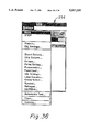
- FIG. 36 is a pictorial illustration of a settings menu screen display of the system diagnostic application of the present invention.
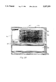
- FIG. 1 shows a pictorial block diagram of a computer-controlled burn-in system which incorporates a universal driver system and which is controlled by operating software of the present invention.
- the system of FIG. 1 has been described in detail in the parent application and is included herein for convenience.
- the previously described main computer 10 having a monitor 12, input keyboard 14, and printer 16 form the central control element for the system thereby forming the vehicle for executing the operating software of the present invention.
- a data bus 18 forms an input-output data link to a multiplicity of burn-in ovens 20 with each oven having a data port 22 which provides two-way access to data bus 18.
- Each of the burn-in ovens 20 is an environmental testing chamber adapted to contain a number of circuit boards (commonly called "burn-in boards) each of which can house a number of electronic devices such as integrated circuits.
- burn-in oven 20 The interior of burn-in oven 20 is accessed through door 21.
- Each burn-in oven has its own monitoring display 24 and manual and automatic controls 26.
- FIG. 2 is a simplified block diagram of a computer-controlled burn-in system which incorporates a universal driver system and which is controlled by operating software of the present invention.
- FIG. 2 has also been described in detail in the parent application and is included herein for convenience.
- an external computer 50 is coupled to a plurality of universal driver systems 100 via computer bus 52.
- Each of the universal driver systems 100 is coupled to a burn-in board 500 by a plurality of input and output signal paths which provide the required digital and analog signals to properly control, exercise and monitor the devices under test (DUT's) that are mounted on each burn-in board as has been previously described in the parent application.
- DUT's devices under test
- Output signal paths which couple from each of the universal driver systems 100 to a burn-in board 500 include power bus 115, analog bus 120 and vector/monitor bus 125. Input signal paths which couple from each burn-in board 500 to a universal driver system 100 include DUT monitors bus 127 and automatic programming bus 129.
- Each burn-in board 500 also includes an identification code means 501 which couples to the associated driver system 100 via automatic programming bus 129. Identification code means 501 allows each burn-in board 500 to be uniquely identified by the operating software of the present invention which is resident and functioning in external computer 50 so that particular sets of stored instructions, and data can be- loaded into a particular driver system 100.
- These sets of stored instructions and data cause the reconfiguring of the electrical properties of the driver system 100 appropriate for the particular devices under test that are installed in the particular burn-in board 500 which is coupled to the driver system 100, as has been described in detail in the parent application.
- the electrical properties of the driver system 100 can be changed by the control exercised by the operating system software of the present invention to meet the requirements of the particular devices under test that are installed in the particular burn-in board 500 which is coupled to the driver system 100 without any hardware change or reconfiguration as would be required for prior art driver systems.
- FIG. 3 is a generalized block diagram of the universal driver system 100 of the present invention and the primary controllable hardware device which is controlled by the computer system of the present invention to be particularly described herein.
- FIG. 3 also has been described in the parent application in more detail and is included herein for convenience.
- a computer bus 52 (a bi-directional bus) couples from an external computer 50 (see FIG. 2) to computer interface module 101.
- Computer interface module 101 contains address logic circuitry which determines that driver data present on computer bus 52 is received by the correct one of a plurality of the universal driver system 100.
- Computer interface module 101 also contains the transceiver and select logic circuitry required to provide direction and control for data being transferred from external computer 50 to the particular modules which comprise universal driver system 100 and, conversely, for data being transferred from the particular modules which comprise universal driver system 100 to external computer 50.
- Computer interface module 101 is coupled to all of the plurality of other modules which make up universal driver system 100 of the present invention by system bus 102 (a bi-directional bus).
- System bus 102 comprises a plurality of signal paths for transmitting and receiving the data and control signals required to control and reconfigure the other modules which make up universal driver system 100 of the present invention.
- system bus 102 couples to power management module 103, system timing generation module 104, vector hold module 105, analog generation module 106, vector storage module 107, tri-state control module 108, automatic programming module 109, DUT monitoring module 110, and on-board status monitoring module 111.
- Power management module 103 functions to measure and regulate the different voltages that are required by the individual modules that make up universal driver system 100 and by the particular burn-in board 500 with which it is associated. Power management module 103 is coupled to tri-state control module 108 by DUT Vcc "On" conductor 114 (an output conductor). Power management module 103 is also coupled to power bus 115 (a bi-directional bus) and onboard power bus 116 (a bi-directional bus). Power bus 115 provides regulated power to the particular burn-in board 500 which is associated with the universal driver system 100 of interest and is not used on the driver system 100 except to provide the point at which the driver system generates and monitors (measures) the voltage conditions existing on the burn in board. On-board power bus 116 provides regulated power to the various modules which make up the universal driver system 100 so that all digital and analog circuits which are part of universal driver system 100 receive their power and precision references from this bus.
- System timing generation module 104 provides programmable master and data clock signals required by the individual modules which comprise universal driver system 100. System timing generation module 104 also provides static and dynamic address sequencing signals to the static random access memory (SRAM) which is part of universal driver system 100. The output of system timing generation module 104 is transmitted on system timing bus 117 (an output bus) which couples to vector hold module 105, analog generation module 106, vector storage module 107, tri-state control module 108, automatic programming module 109 and DUT monitoring module 110.
- SRAM static random access memory
- Vector hold module 105 functions to extend the time interval of stored data patterns so that longer data sequences required to exercise devices under test can be generated without requiring additional memory.
- the output of vector hold module 105 is produced on the hold signal path 118 (an output path) which couples to system timing generation module 104 which then imposes hold requirements via system timing bus 117.
- Analog generation module 106 uses digital-to-analog converter (DAC) circuitry to generate a range of analog signals such as sine waves, square waves, ramp waves, and the like based on programmed patterns transmitted from external computer 50.
- the output of analog generation module 106 couples to analog driver module 113 via analog bus 119 (an output bus).
- Analog driver module 113 functions to provide additional current drive capability for the analog channels thereby allowing them to drive higher current loads.
- the output of analog driver module 113 couples to driven analog bus 120 (an output bus) which couples to the analog channels 121 which couple to the analog channel inputs of the burn-in board 500 (not shown) associated with this particular universal driver system 100.
- Vector storage module 107 functions by using SRAM to provide the large digital storage area which retains the test data patterns ("vectors") which define the digital signals which will be applied to the devices under test (DUT's) which are housed in the burn-in board 500 associated with a particular universal driver system 100.
- the output of vector storage module 107 couples to vectors bus 122 (an output bus) which in turn couples to on-board status monitoring module 111 and to output driver module 112.
- Tri-state control module 108 functions to provide an additional dimension of output driver control by allowing a particular output driver to be switched to high-impedance or disconnected state in addition to the drivers normal ON (Current sourcing) and normal OFF (current sinking) states.
- Tri-state control module 108 produces one set of outputs on tri-state vectors bus 123 (an output bus) which couples to output driver module 112.
- Tri-state control module 108 produces a second set of outputs on tri-state bus 124 (an output bus) which couples to output driver module 112.
- Output driver module 112 functions to provide additional current drive capability to the DUT's housed on the associated burn-in board 500 (not shown). Output driver module 112 also functions to allow universal driver system 100 to change the high level voltage (Voh) that is being applied to the DUT's housed on the associated burn-in board 500 (not shown). Output driver module 112 produces a set of outputs on driven vector bus 125 which couples to on-board status monitoring module 111 and to vector channels 126 which couple to the vector channel inputs of the burn-in board 500 (not shown) associated with this particular universal driver system 100. On-board status monitoring module 111 functions to monitor for faults that may occur within the various module elements which comprise universal driver system 100.
- On-board status monitoring module 111 is coupled to vectors bus 122 (an input bus), to driven vector bus 125 (an input bus), to tri-state bus 124 (a bi-directional bus) and to system bus 102 (a bi-directional bus).
- DUT monitoring module 110 functions to provide information about the operating condition of DUT's on the associated burn-in board 500 (not shown) to the external computer which is controlling and altering the operation of a particular universal driver system 100. This information is obtained by comparing data received from the DUT's on the associated burn-in board 500 with expected data (stored in SRAM by the external computer). When this comparison shows a difference, the information is passed to external computer 50 for data logging.
- DUT monitoring module 110 also couples to system timing bus 117 (an input bus) and to system bus 102 (a bi-directional bus).
- Automatic programming module 109 functions to provide a serial to parallel interface which translates the identification code which uniquely identifies a particular burn-in board 500 (not shown) that is associated with a universal driver system 100 to the external computer 50 as has been previously discussed.
- Automatic programming module 109 couples to ID code bus 129 (an input bus) which is in turn coupled to the automatic programming channels 130 from the associated burn-in board 500 (not shown). Automatic programming module 109 also couples to system timing bus 117 (an input bus) and to system bus 102 (a bi-directional bus).
- FIG. 4 is a functional relationship diagram summarizing the operating functions of the universal driver system of the present invention. Each of these functions has been described individually in terms of the operation of the constituent modules of the driver system already described herein and in the parent application.
- a burn-in sequence begins with the READ ID CODE block indicating the process by which the external computer identifies the particular burn-in board connected to a particular driver and correspondingly determines from its program the particular "project" that will be required for the devices known to be installed on the identified burn-in board.
- the execution of the computer program then causes the reconfiguration of the individual modules of the driver system as required.
- This reconfiguration includes the read-write sequences for PROGRAM ANALOG, PROGRAM MONITORING, PROGRAM DUT MONITOR, PROGRAM BOARD VOLTS, PROGRAM DUT VOLTS and PROGRAM FREQUENCY as dictated by the functional requirements of the individual driver modules previously described. These sequences can occur in any order and will be determined by the needs of an efficient programming sequence. Similarly, the execution of the computer program also causes storage of required vector and auxiliary control patterns in the SRAM modules of the driver system in accordance with the needs of the devices known to be installed on the identified burn-in board.
- sequences can be altered based on detected changes in the operating condition of devices under test through use of the MONITOR ANALOG function thereby creating a driver system which is highly versatile.
- This versatility is a key advantage of the present invention in that all of these changes in test condition can be accomplished quickly without removing the driver system from the burn-in environment and without making any mechanical changes.
- This feature bootstraps a still further advantage in that the existence of a single mechanical design allows this design to be optimized for high frequency operation so that devices under test can be operated at much higher internal clock rates so that overall burn-in cycles can be shortened.
- a central concept in the operation of the universal driver system is the creation of a particular set of stored instructions and data called a "project" required to cause the reconfiguring of the electrical properties of the driver system 100 appropriate for the particular devices under test that are installed in the particular burn-in boards of the system.
- a project file is a complete collection of configuration and vector pattern information that is later downloaded to the driver 100.
- Two components comprise the project: a Pattern, a collection of signals and vectors at a given address channel; and Latched Settings or Static parameters, i.e., voltage and frequency, that are set only once for a particular driver.
- a sequence file is a group of Events and Actions that duplicate or extend the burn-in driver board's capability by allowing quick re-configuration of the driver 100.
- the sequence allows the user to change DUT stresses based on time, temperature, or number of times that the test is run.
- the driver 100 of the present system can be re-programmed without direct human intervention.
- the sequence can be thought of as a burn-in cycle or plan.
- An Action is a single operation within a given Event for a specific driver 100.
- An Event is a group of Actions.
- the project file for a particular device comprises the complete collection of configuration and waveform pattern information which is subsequently downloaded to the driver 100 associated with that device.
- the operating system software of the present invention groups all of the essential configuration data together and presents it to the system user in the form of a single element which is the project.
- the system of this invention provides the electronic industry with a complete burn-in package that aids in the development of new product burn-in processes within a few hours. This capability leads to a lower cost and more controlled burn-in process.
- the system focuses on two physical entities--the driver of the present invention and the software of the present invention.
- the system focus is on burn-in chambers and burn-in data network.
- the product focus moves from manufacturing new burn-in hardware to the development of the intricate burn-in cycle processes. Aided by graphically-based Windows@ software, the user's focus becomes directed to the DUT instead of the burn-in driver.
- the present system uses two main software environments.
- the development tools constitute a collection of software packages that allows for the creation of two software file collections, called, again, the project (as further described in the parent application) and the sequence.
- the project and sequence are control files that allow for the programming of drivers 100 and maintaining the burn-in cycle, respectively.
- the production tools constitute a set of software packages that allows the user to run the drivers 100 with the project and sequence files on the actual burn-in system.
- the system of the present invention automates data collection and storage using drivers 100 that test the DUTs during burn-in.
- the user has the ability to retrieve stored information for use through user-friendly, statistical analysis software.
- the user also has the ability to export the stored information for use in other software packages.
- FIG. 5 is a system-overview diagram of the burn-in control computer applications (later described in detail) of the present invention.
- the waveform editor application 201 (also herein referred to as the vector editor or the project editor), wherein projects are designed and stored, transmits, when requested, a selected project file (denoted .prj) to the sequence editor application 202 and/or the system diagnostic application 203 (also herein called system test control or UDS application), a universal diagnostic system.
- the sequence editor wherein sequences are designed and stored, transmits, when requested, a selected sequence file (denoted .seq) to the system control application 204 (also herein called the system controller).
- the system editor application 205 wherein burn-in system configurations are designed and stored, transmits, when requested, a selected system configuration file (denoted .ovn) to the system control application 204.
- a selected system configuration file denoted .ovn
- the system diagnostic application 203, the system control application 204, and the system editor application 205 all have connections with the generally denoted burn-in system hardware 206 as elsewhere herein and in the parent application described.
- FIG. 6 is a block diagram of the computer software system for burn-in control of the present invention which shows more specifically the structures and major functional connections of those software systems (more specifically elsewhere described).
- the wave form editor application 201 includes vector editing means 207, waveform display means 208 and vector storage means 209.
- the sequence editor application 202 includes sequence editing means 210, sequence display means 211, and sequence storage means 212.
- the system editor application 205 includes system editing means 213, system display means 214 and system storage means 215.
- the system control application 204 includes system control means 216 and sequence amendment means 217.
- the burn-in system hardware 206 includes driver means 100 (the universal driver system previously described in detail herein and in the parent application).
- the waveform editor application 201 permits independent setting as vector data of vector parameters for testing a semiconductor device.
- Waveform display means 201 permits graphic representation of test waveforms for multiple channels, to assist in such setting of vector parameters.
- Vector storage means 209 permits storing such vector data as an identified project file (.prj) to be used to configure driver means 100.
- the sequence editor application 202 permits independent setting as sequence data sequential parameters for controlling the testing of semiconductor devices.
- the sequence editing means 210 includes command means for including a project file from vector storage means 209 as a sequential parameter.
- the sequence storage means 212 permits storing such sequence data as an identified sequence file (.seq) to be used to control burn-in system hardware 206, including driver means 100.
- the system editor application 205 permits graphically setting as burn-in system data a burn-in system configuration for controlling the testing of a semiconductor device.
- System storage means 215 permits storing such burn-in system data as an identified burn-in system file (.ovn).
- the system control application 204 includes in system control means 216 command means for including a such burn-in system file from system storage means 215 and command means for including a such sequence file for use to control hardware 206, including driver means 100.
- the system control application 204 also includes sequence amendment means 217 for mid-test amendment of sequence parameters reactively in response to receipt from driver means 100 of selected test data concerning the semiconductor device under test.
- the system diagnostic application 203 includes system diagnostic means for testing the burn-in system hardware 206 and includes command means for using a project file (.prj) to reconfigure driver means 100.
- Waveform display means 208, sequence display means 211, and system display means 214 are preferably menu-based, interactive, graphic displays.
- FIG. 7 is a diagrammatic chart of the steps of the system method of burn-in control of the present invention, showing the general flow among the steps of the system's method.
- Each box of FIG. 7 represents the step illustrated, with the solid-line connections between boxes representing a preferred order or flow among steps.
- the circle, as shown, represents the hardware systems and functions of the present invention. And the dotted lines show the steps involving interaction with such hardware.
- the step SET VECTORS represented by box 221
- the step DISPLAY GRAPHIC WAVEFORMS, box 222 includes computer-displaying graphic representation of test waveforms for multiple channels during such computer-setting of such vector parameters.
- the step STORE AS project FILE (.prj), box 223, includes computer-storing such vector data as an identified project file (.prj) and in form for use to configure burn-in driver means 100.
- the step SET sequence, box 224 includes independently computer-setting as sequence data sequential parameters for controlling the testing of semiconductor devices and including as at least one of such sequential parameters a such project file.
- the step STORE AS sequence FILE, box 225 includes computer-storing such sequence file as an identified sequence file and in form for use to control the burn-in hardware, including burn-in driver means 100.
- the step SET SYSTEM CONFIGURATION, box 226, includes graphically computer-setting as burn-in system data a burn-in system configuration for controlling the testing of semiconductor devices.
- the host PC computer system have the following hardware and software configuration to install and run the software of the present invention successfully: Microsoft@ Windows@ Version 3.1 or later, running in a standard or 386 enhanced mode; a 386 PC or better; MS-DOS@ 5.0 or later; 100 MB free hard disk space; 8 MB memory; one 5.25-inch high-density disk drive, or one 3.5-inch high-density disk drive; Microsoft@ mouse or compatible pointing device; and SVGA Monitor (17 in. or larger recommended).
- the present system significantly reduces the time to design drivers and change testing parameters.
- the burn-in design cycle can now be reduced to several hours.
- the user can use the system's software applications and almost instantly re-configure a burn-in driver to test a new DUT.
- the user may construct a sequence of projects.
- the user can change patterns, voltages, frequencies, etc., to build projects quickly and easily through the software which eliminates need to design new drivers.
- the system controller is used to download sequences and projects to different driver boards 100.
- the user can enter an information file into the system for one driver.
- the user can then quickly change the testing parameters and change the driver 100 to test a different DUT.
- the user no longer needs to manually input the test parameters at the hardware level.
- the various software applications of the present invention allow the user to directly import vectors of information and to quickly choose the voltages, frequencies and other hardware capabilities without having to design new, or modify old, equipment.
- Each of the software applications of this invention are responsible for a small segment of the burn-in process.
- the presently preferred system contains six software applications that aid the user in performing burn-in process.
- the system's security program provides that each user must obtain security access in order to run any of the system's software applications.
- the system controller application directs the burn-in cycle, allowing the user to view DUT failures as they occur.
- the user can also use this application to move between processes (i.e. system view, to chamber view to zone view).
- the universal diagnostic shell application is an internal tool that allows the user to test BIBs, drivers and other system hardware. This application exercises the drivers.
- the system editor application allows the user to create a graphical depiction of the location of drivers and BIBs within the system.
- the waveform editor also called vector editor
- the waveform editor application allows the user to input information to create new projects, or modify previously stored projects. This is where the user enters the data (i.e., frequency, voltages and test patterns) that varies from one product to another.
- the sequence editor application allows the user to program the burn-in cycle to the drivers by creating sequence files that contain Events, Actions and other features executed at run-time.
- the software of the present invention contains four distinct areas. Each area is dependent on the other. In the security layer area each user gains access to all system applications.
- the editor family layer area contains the editor files used to create files or documents necessary for a complete and vigorous design flow of information to the hardware. The editors allow the user to easily create projects, sequences, and graphical depictions of a system. The engineer will spend the most time working in this area.
- the editor family layer includes a full list of features specific to each editor. A consistent user interface remains throughout all applications.
- the system family layer area contains applications that converse with the system hardware boards. This layer allows the user to graphically display systems and chambers, configure drivers, and monitor for errors on the DUT level. The system family is responsible for hardware and maintains the hardware's integrity.
- the user may confidence test the hardware.
- This layer is not only responsible for handling the diagnostics for one type of driver, but could handle all types concurrently if the case existed.
- the user In this layer the user must set up a specific driver that operates on the bit level and then toggles the bits ON or OFF located on the driver board.
- the user must have access to security in order to run any application in the system.
- the user can run the security system directly by entering the security system icon or by starting any of the other system applications.
- the security system requires a security key that allows the system to run. This key fits on the parallel port of the computer. If an application is running, and a user removes the security key, all system applications will close. The goal of the security system is to maintain the overall system's software's integrity. Without the security system, none of the other system applications will run (see FIG. 8). For example, from the opening software screen showing icon entries to all of the system's applications, if the user clicks the UDS icon twice with the mouse pointer to open that application, the initial security screen 218 (see FIG.
- one user receives the designation of administrator.
- the administrator has the ability, through the security system, to maintain a user list.
- the administrator can add or delete the number of users on the system, as well as selecting the programs that an employee can use.
- the administrator also gives each user a security level and a password used to run the various system applications. So each user that works with the present system preferably receives a separate password that needs to remain confidential at all times.
- the waveform editor 201 is an application in the present system that allows the user to program data information into a new project by creating a project file (.prj). The user can also continue to develop previously stored projects.
- This application presents an interactive method for editing vector data and driver settings for later use.
- the waveform editor display 208 presents each of the configuration elements for editing to the user in the form of pull down menus. Each menu is logically grouped to include all the same type of information which segregates the features of the system hardware for easy reference.
- the primary goal of the waveform editor 201 is to create a project file that can be used with any system driver 100.
- the files created by the waveform editor 201 are downloaded and used in two other system applications, the UDS 203 and the sequence editor 202.
- the development of waveforms is essential to the burn-in cycle of the present system.
- the waveform editor application 201 allows the user to easily program in a matter of minutes for a system driver 100 to be given a specific state.
- the waveform editor application 201 is the software compliment to the system drivers 100.
- the waveform editor application 201 supports a vast array of editing features for creating or modifying bit wise signals.
- the user can modify or program vectors to meet a specific need. Functions include ANDing, COMPLEMENTing, INVERTing, ORing, XORing, pulse generation, and address generation.
- the waveform editor 201 maintains project control (see FIG. 10) by requiring the user of the project information screen 232 to enter version number (at 233), the day the project was created or revised (at 234), the person who did the editing (at 235), and comments (at 236). The user can modify many features of the waveform.
- Some of these features may include: latched based features (e.g., frequency, voltage, idle settings), flat vectors, hold channels, sub vectors, tri-state control, and scan control.
- the user has the ability to create a digital channel, download the channels to a driver, and output the channels to a DUT as the drivers are run.
- the waveform editor 201 contains hold channels and flat vectors that are very simple to create and edit. In the system of the present invention, the user does not need extensive knowledge of the waveform editor 201 to modify or create a waveform. The modifications can be as simple as typing in a frequency or voltage change into the appropriate dialog box.
- the waveform editor display 208 graphically presents vector data in a timing diagram display.
- FIG. 11 Various data points are displayed in waveform fashion with a different color for each information channel (see FIG. 11).
- the creation or editing of waveforms is just as easy.
- the user just has to click on a bit in the flat vector screen 235 and the vector is quickly changed (see FIG. 12).
- the user can choose which number base to enter the information about a particular waveform from the list dialog box located in the upper right hand corner of the screen (see FIG. 13): hexadecimal, decimal, binary, or octal.
- the user can also view the data in an addressed or time based format.
- the user can input test data using Intel@ HEX, ASCII and Motorola@ S-record format, directly from the simulators and testers.
- the data is inputted automatically and mapped directly to the system hardware.
- Channel swapping supports simple and efficient re-mapping of signal output channels to the BIB.
- the signals graphically depict the tri-state levels. This feature determines when groups of signals are in the tri-state mode without reference to signal mapping charts.
- Historical and revision information records include automatic revision number incrementing, logged in user information and text comments.
- Other features of the preferred waveform editor 201 include: Open existing file, Save active document, Editing functions (i.e., Cut, Paste, Copy, and Print), Zoom in signal horizontally, Zoom out from signal horizontally, Zoom in signal vertically, Zoom out from signal vertically, Zoom in signal horizontally and vertically, Zoom out from signal horizontally and vertically, Display program information, version number, and copyright, and Display help for clicked on buttons, menus, and windows.
- Editing functions i.e., Cut, Paste, Copy, and Print
- the system editor 205 allows the user to create a file (.ovn) that contains a description (number and position of chambers, drivers, and zones) of a particular system and the location of the drivers 100 within that system.
- a file (.ovn) that contains a description (number and position of chambers, drivers, and zones) of a particular system and the location of the drivers 100 within that system.
- the system editor 205 automatically scans the system for the number of installed drivers 100 and respective version IDs.
- the file (.ovn) created in the system editor 202 is used in another system application, the system controller 204.
- the accuracy of the chamber configuration is important since the .ovn file holds the user's view of the chamber as the drivers 100 are used.
- the configuration of the system should resemble the one that will be used on the production floor.
- the system editor 205 designs the interface between the hardware and software.
- the system editor hardware is essential for the chamber configuration to function successfully.
- the configuration is a one time process.
- the user need only to design one configuration that is used by the system controller 204 to display the graphical representation of the system. For example, the user clicks the system editor icon twice with the mouse pointer to open the application.
- the system editor initial screen 236 (see FIG. 14) will appear.
- the user selects either the File menu (at 237) or the new system file button (at 238) to create a new .ovn file.
- the New System Type Dialog Box 238 (see FIG. 15) is displayed.
- the user then enters a new system name (at 240), then enters the number of chambers (at 241), zones tall (at 242), zones wide (at 243), drivers tall (at 244), and drivers wide (at 245).
- the system editor 202 then draws the system in display 246 without the drivers, as shown in FIG. 16.
- a driver is then selected by clicking a (white) driver-representation box.
- the Driver Dialog Box 248 (see FIG. 17) will appear.
- the user then enters the desired I ⁇ O card number (at 249) and driver number (at 250).
- the driver version number will be displayed (at 251), and the user clicks OK (at 252).
- the driver and .ovn file are now created.
- there are two ways to save a file click the File Menu and then save; or click on the File Save button.
- the information is now saved as an .ovn file. To exit this application, the user clicks the exit icon.
- Exit system editor Open new system file, Load a system file, Save the current system, Zoom in, Zoom out, Re-size current system, Set the card address, Check which drivers are loaded, View the loaded drivers, and Activate context sensitive help.
- sequence editor 202 of the present invention one must know that, during a typical burn-in cycle, there are six basic steps that the user performs: (1) Download a project; (2) Set the idle settings and/or Actions and Events that will occur during the sequence; (3) Run the driver for any amount of time desired, during which time the user checks that the drivers are running, that the fuses are functioning, and that there are BIBs attached; (4) Download another project; (5) Set another period of time; and (6) End the sequence.
- the sequence editor 202 of the present invention allows the user to perform batch processing for a number of sequences, i.e., automation through the sequence editor 202 that allows the user to list any number of Actions and Events that will occur over a period of time quickly instead of having to perform the same steps manually.
- the sequence editor allows the user to create a new sequence, open a previously created sequence, or edit the sequence. Editing a sequence can involve many procedures. A user could add or delete Actions and Events contained within a sequence, move Actions and Events within a sequence, and/or add or delete global Actions.
- the sequence Editor display screen 211 is divided into three main areas (see FIG. 18).
- the Global Actions section 253 displays three actions that occur automatically during a sequence: checking the status of a driver; checking the fuses on the driver; and checking the existence of all marked BIBs.
- the sequenced Events section 254 displays the Events and Actions chosen by the user that will occur during a sequence.
- the larger window 254 is the Event.
- the smaller window 253 on the top of the Event is the Action.
- the Preferences section 256 allows the user to manually keep the sequence running. If the user does not select this box, the sequence will stop at the end of the cycle. project and pattern sequencing are useful to perform functional tests of DUTs. This application allows the user to select various chips to test on a regular basis. The user also has the ability to select different DUTs located at various positions on the BIB.
- the goal of the sequence editor application 202 is to allow the user to create a sequence that exercises various features--i.e., voltage, frequency, etc.--of a particular driver type.
- the sequence editor 202 interacts with two other system software applications, the system controller 204 and the waveform editor 201.
- the sequence editor 202 takes the .prj file from the waveform editor 201 and places the information as an Action of a sequence. In this manner, the sequence editor application 202 creates a .seq file directly associated with the driver 100 tested by the system controller 204.
- the sequence editor 202 creates a sequence of events that tests the DUT under specific parameters over a given period of time.
- This application 202 allows for DUT testing in various controlled environments in one burn-in cycle.
- a sequence could be as simple as downloading a project or as complicated as setting voltages, frequencies, idle settings, vector delays and loops to repeat the test.
- the sequencing concept is a very powerful idea. Sequencing can accomplish almost all processes relating to the
- the user may proceed as follows. To open the sequence editor 202 from the main system screen, the user clicks the mouse pointer on the sequence editor icon twice. The initial sequence editor screen display 258 (see FIG. 19) will appear. The user then clicks the File menu in the upper left hand corner once to open a specific file. The File Menu screen 260 (see FIG. 20) will appear. The user can choose to open an old or new sequence. If the user clicks "New sequence" (at 261), the Driver Version Dialog Box 262 (see FIG. 21) appears. The user may, for example, choose Version 9, then click OK. The main sequence editor screen 263 is then displayed (see FIG. 22).
- the sequence editor 210 automatically calls the sequence noname.seq.
- the sequence editor application 202 places three global actions into the sequence: driver conditioning; fuse monitoring; and BIB monitoring.
- the next step is to create an event for the sequence to download to the project.
- the user selects the project button 264 near the top of the screen and places the cursor into the sequence events window 265.
- the cursor will change as it enters the sequence Events window 265.
- the user clicks the left mouse button to place projects, Actions, and Events. Clicking the mouse button lists the different projects from which the user can choose to save the sequence (see FIG. 23).
- the user selects, for example, nr.prj and clicks OK.
- the right mouse button allows the user to place a red dotted line around an Action or an Event so that particular function can be modified within a sequence. Also, the number of times the end of a vector set has been reached is counted and displayed.
- the Preference function allows the user to manually stop a sequence. Note that the user has to physically tell the sequence editor 202 to stop or the sequence will continue to run.
- Some other features included in the sequence editor 202 of the present invention are: Display help index, Create a new sequence, Open an existing sequence, Save this sequence, Close window, Exit sequence Editor, Add event(s) to beginning of a sequence, Add event(s) to end of a sequence, Move event(s) to beginning of a sequence, Move event(s) to end of sequence, Download a project to a driver, Update a frequency setting on a driver, Update the voltage settings on a driver, Download a pattern file to a driver, Set the idle frequency setting for a driver, Set the vector delay settings for a driver, Perform a chip select with a driver, Perform a static chip select with a driver, Mark an event for later reference, Loop to a marked event, Check the status of a driver, Check the fuses on a driver, and Check for the existence of all marked BIBs.
- the system controller 204 of the present invention is the application that controls the actual burn-in testing of the DUT.
- the system control application 204 gives the user the ability to manage execution of the sequence and to monitor drivers, BIBs, and DUTs on the production floor. The user can view the number of chambers, zones, BIBs, drivers, and DUTs associated with any given system upon execution of the program.
- This application displays 272 the information about a file in a hierarchical manner: the system information 273 first, then the chamber 274, zone 275, driver 276, BIB 277 and the DUT 278, (see FIG. 27).
- the system controller's design supports a touch screen capability. Each feature on the screen is large enough for a finger.
- the primary goal of the system controller 204 is to give the user a simple, efficient way to manage the resources of performing burn-in at chamber to chamber level.
- the system controller 204 is the last level of preparing for testing a particular DUT.
- the system control application 204 incorporates information from all other system applications into a simple overview for testing.
- the system controller 204 may be operated, for example, as follows. The user may click the system controller icon twice with the mouse pointer to open the application and the main screen 279 will be displayed (see FIG. 28). This screen 279 is displayed into seven major sections.
- the far left window is the System Selection Window 280 that displays the available systems, chambers, zones, driver boards, BIBs and DUTs in hierarchical manner, as previously described.
- the window at the top of the screen is the Title Window 281 that shows the systems, chambers, etc., that the user is currently testing.
- the window below the title screen is the Viewer Window 282 that displays the available BIBs.
- the section below the System Selection Window 280 holds the buttons 283 that the user applies to start, stop and pause the system testing.
- the button bar 284 on the far right side holds the icons used for various features of the system controller 204 (i.e. load sequence, DUT masking, Log View, etc.).
- the window below the View Window 282 is the System Log Window 285. This window displays messages about the system, such as successful or driver fail notices. The user always logs this material to a disk or an external source, such as a printer.
- the window at the bottom of the screen is the Status Window 286. This window 286 displays brief how-to help messages for the user about various applications. The user may then select a driver by clicking the View Screen which will change colors. In a preferred embodiment hereof, there is a color scheme associated with the main screen when it displays chambers, drivers, etc.
- the code is green when the device (driver, chamber, etc.) is present, blue when the device is selected, and gray when the device is not present.
- the user may load a particular sequence by clicking the sequence button located on the right side of the screen on button bar 284.
- the Load sequence Screen 287 (see FIG. 29) will be displayed.
- the user can select the desired sequence, by either clicking on the sequence name and then choose OK, or clicking the sequence twice. This action loads the information necessary, number of chambers, BIBs, zones, etc., to test the sequence.
- the main color screen 263 will return to a non-selected state.
- the user then re-selects the driver.
- the sequence is now ready to run.
- the user may now select GO.
- the report on the status of the test will appear in the System Log Window 285.
- the user has the option to print the test results to the printer by clicking the printer icon once to enable the printer. To disable the printer, the user clicks the icon again.
- the small square in the upper left hand corner of the main screen 279 will flash yellow.
- the user may exit the application by clicking the exit icon on the right-hand side of the screen 279.
- Some other features of the system controller 204 are: Exit UDS, Open burn-in driver version, Select a driver, Run a driver, Stop a driver, Download a project, Set voltage settings, Set frequency settings, Set special settings, and Program/Read EEPROM. Some of the features included in the settings menu are:
- Idle Settings --Allows the user to tell the hardware what to do when it is not running
- a toggle demonstration mode (used when no hardware is
- the user can monitor more than one DUT during the burn-in cycle.
- the system controller 204 records information (i.e. errors, if the driver is initiated, how many DUTs are tested etc.) into a System Log File.
- the present system reduces the steps of DUT monitoring.
- the user downloads the project to the driver 100.
- the driver 100 contains the test parameter information and the expected results of the test.
- the driver 100 is set in run mode.
- the driver 100 then sends the data to the DUT, all as more particularly described hereinbefore and in the parent application.
- the information is received from the DUT.
- the driver 100 compares the expected results with the results from the test. If the resultant information does not match the expected results, the driver 100 records the mismatch as an error, otherwise the DUT passes.
- the present system contains a Log Viewer application, located in the system controller software 204, that allows the user to view the log file and to post process the file for data analysis.
- the log file in the system controller 204 contains all the pertinent information about the test (i.e. number of failures, time the errors occurred, when the test was run, if the drivers were exercised, etc.), and displays it in a useful visual format.
- the user can display the data in several graphical formats.
- the System Log can count how many times that a particular DUT has failed and automatically log the error. When the failures are counted, the driver 100 resets the bit and the test is repeated. If the same error occurs, it is then entered into the log file for later retrieval.
- the UDS application 203 is an important and useful part of the system of the present invention as a diagnostic tool.
- the UDS 203 allows the user to have an internal tool in which to test the BIBs, drivers, and other system hardware items associated with the burn-in process.
- the testing of the system hardware occurs on a manual level where the user can change the setting parameters (i.e. voltage and frequency).
- the UDS 203 allows for the testing of multiple versions and features of burn-in driver boards.
- the main goal of the UDS 203 is to provide the user direct control over the testing of all hardware aspects.
- the UDS 203 primarily interacts only with the hardware. However, this application 203 does use project information from the waveform editor 201 (refer to FIG. 5.1) and tests such information on the driver 100.
- the UDS 203 is a low level program that communicates directly to the hardware. It is noted that, before the UDS 203 can test any hardware for a particular version, a latch file must be created.
- the user may operate the UDS 203, for example, as follows.
- the user may click the UDS icon twice with the mouse pointer to open the application.
- the initial UDS Screen 288 (see FIG. 30) will appear.
- the user may then click the File menu in the upper right hand corner, or the file icon, once to open a specific file.
- the Version Display Dialog Box (see FIG. 31) will appear.
- the user may then click "Open Version", choose the desired version, and click OK.
- the UDS 203 automatically opens all information programs associated with the selected driver.
- the Status Window Screen 290 (see FIG. 32) will appear. Click on the new button to select a driver.
- the Select a Driver Screen 291 (see FIG. 33) will appear.
- the user may then select the appropriate address (e.g., 300 hex and driver number) from the screen. (Note that the I ⁇ O card address is hexadecimal and generally stays the same and is referred to as the based address. However, the address might often change depending on which driver is accessed.)
- the user may then click OK. If the driver is present, or an error occurs, it will be displayed in the status window.
- the Information about a Driver Screen 292 (see FIG. 34) is displayed.
- the user may then download a project by either clicking on the project button or applying the settings menu. This action displays a File Selection Box 293, (see FIG. 35).
- the user may then choose the appropriate file and click OK.
- the status window opens when the driver address is selected.
- a message will appear if the communication to hardware is successful or if there is an error occurring.
- the user may then click on the GO button to start the test defined by the project that has been downloaded to driver 100.
- the user can change various parameters during testing by use of the settings pull down menu 294 (see FIG. 36).
- the user may click the STOP button.
- the user may exit the UDS 203 by either clicking on the exit button or by using the File menu.
- the system software of the present invention contains its own installation utility.
- the setup program is a standard Microsoft@ Windows@ based setup utility with customized features. Backup, for instance, allows a user that already has the system software to save the old version and install a new copy.
- the setup screen prompts the current user for their name and company name.
- the Windows@ Program Manager creates a group containing the icons needed for the present applications.
- the user to install the software for Windows on the computer hard drive, performs the following steps: (1) Start Windows@; (2) Insert the first Setup and Applications disk into the floppy drive of the computer; (3) In Windows@ Program Manager, choose File Run; (4) A dialog box will prompt for the name of the file to run; (5) If installing from a floppy drive a:, type a: ⁇ setup.exe.; (6) Press ENTER and a dialog box appears after initializing the setup program and prompting filling out the product registration box; (7) Under the instructions on the screen to prompt the user to enter the path wanted for installation of the system software; (8) A dialog box will appear on the screen if multiple versions of the software will be overwritten. It will create a ⁇ BACKUP directory in the destination path to back up files selected. The user may skip this step if the destination path is empty; (9) When the setup procedure is complete, a dialog box will appear, and the software is ready for use.
- the following information is basic procedure for installing the software key of the security system.
Abstract
Description
Claims (60)
Priority Applications (1)
| Application Number | Priority Date | Filing Date | Title |
|---|---|---|---|
| US08/173,618 US5557559A (en) | 1992-07-06 | 1993-12-23 | Universal burn-in driver system and method therefor |
Applications Claiming Priority (2)
| Application Number | Priority Date | Filing Date | Title |
|---|---|---|---|
| US07/908,968 US5390129A (en) | 1992-07-06 | 1992-07-06 | Universal burn-in driver system and method therefor |
| US08/173,618 US5557559A (en) | 1992-07-06 | 1993-12-23 | Universal burn-in driver system and method therefor |
Related Parent Applications (1)
| Application Number | Title | Priority Date | Filing Date |
|---|---|---|---|
| US07/908,968 Continuation-In-Part US5390129A (en) | 1992-07-06 | 1992-07-06 | Universal burn-in driver system and method therefor |
Publications (1)
| Publication Number | Publication Date |
|---|---|
| US5557559A true US5557559A (en) | 1996-09-17 |
Family
ID=46248906
Family Applications (1)
| Application Number | Title | Priority Date | Filing Date |
|---|---|---|---|
| US08/173,618 Expired - Fee Related US5557559A (en) | 1992-07-06 | 1993-12-23 | Universal burn-in driver system and method therefor |
Country Status (1)
| Country | Link |
|---|---|
| US (1) | US5557559A (en) |
Cited By (44)
| Publication number | Priority date | Publication date | Assignee | Title |
|---|---|---|---|---|
| US5822717A (en) * | 1995-07-31 | 1998-10-13 | Advanced Micro Devices, Inc. | Method and apparatus for automated wafer level testing and reliability data analysis |
| US6029262A (en) * | 1997-11-25 | 2000-02-22 | Mosaid Technologies Incorporated | Graphical editor for defining memory test sequences |
| FR2787903A1 (en) * | 1998-10-22 | 2000-06-30 | Dell Usa Lp | METHOD AND DEVICE FOR TESTING COMPUTERS IN MANUFACTURE USING STATUS AND ATTRIBUTE INFORMATION |
| US6124707A (en) * | 1996-09-16 | 2000-09-26 | Samsung Electronics Co., Ltd. | Tester for peripheral storage device |
| US6175812B1 (en) * | 1998-02-26 | 2001-01-16 | Micron Technology, Inc. | Method and system for dynamic duration burn-in |
| EP1136833A1 (en) * | 2000-03-23 | 2001-09-26 | Infineon Technologies AG | Method of performing a burn-in process to electrically stress a semiconductor memory |
| US6323665B1 (en) | 1997-10-07 | 2001-11-27 | Reliability Incorporated | Apparatus capable of high power dissipation during burn-in of a device under test |
| US6329831B1 (en) * | 1997-08-08 | 2001-12-11 | Advanced Micro Devices, Inc. | Method and apparatus for reliability testing of integrated circuit structures and devices |
| US6336199B1 (en) * | 1998-08-31 | 2002-01-01 | Mitsubishi Denki Kabushiki Kaisha | Computer-readable recording medium storing a method of masking or modifying output events of bi-directional signals in an event-format test pattern file for a semiconductor integrated circuit |
| US6467153B2 (en) * | 1997-06-11 | 2002-10-22 | Western Digital Technologies, Inc. | Method for manufacturing a disk drive |
| US20020157053A1 (en) * | 2001-04-21 | 2002-10-24 | Chen Leon Lee | Semiconductor test system with time critical sequence generation using general purpose operating system |
| US6477486B1 (en) | 1998-09-10 | 2002-11-05 | Dell Usa, L.P. | Automatic location determination of devices under test |
| US6477095B2 (en) * | 2000-12-28 | 2002-11-05 | Infineon Technologies Richmond, Lp | Method for reading semiconductor die information in a parallel test and burn-in system |
| US20020199142A1 (en) * | 2001-06-26 | 2002-12-26 | Moshe Gefen | Semiconductor programming and testing method and apparatus |
| US20030001604A1 (en) * | 2001-07-02 | 2003-01-02 | Intel Corporation | Integrated circuit burn-in methods and apparatus |
| US6542928B1 (en) * | 1998-06-02 | 2003-04-01 | Micron Technology, Inc. | Automatic configuration of testers and hosts on a computer network |
| US6546510B1 (en) * | 1998-07-13 | 2003-04-08 | Texas Instruments Incorporated | Burn-in mode detect circuit for semiconductor device |
| US6654347B1 (en) * | 1999-10-22 | 2003-11-25 | Dell Usa L.P. | Site-to-site dynamic virtual local area network |
| US6678850B2 (en) * | 1999-03-01 | 2004-01-13 | Formfactor, Inc. | Distributed interface for parallel testing of multiple devices using a single tester channel |
| US6701283B2 (en) | 2001-05-15 | 2004-03-02 | Dell Products L.P. | Apparatus for processing items of electronic equipment |
| US6744269B1 (en) | 1997-10-07 | 2004-06-01 | Reliability Incorporated | Burn-in board with adaptable heat sink device |
| US6807507B2 (en) | 2001-11-27 | 2004-10-19 | Vasudevan Seshadhri Kumar | Electrical over stress (EOS) monitor |
| US7062399B1 (en) * | 2000-06-02 | 2006-06-13 | Advance Micro Devices, Inc. | Resistivity analysis |
| US20070006038A1 (en) * | 2005-06-29 | 2007-01-04 | Zhengrong Zhou | Methods and apparatus using a hierarchical test development tree to specify devices and their test setups |
| US20070145993A1 (en) * | 2005-12-26 | 2007-06-28 | Hon Hai Precision Industry Co., Ltd. | Chip burning system |
| US20070245199A1 (en) * | 2006-03-31 | 2007-10-18 | Robert Pochowski | Application Specific Distributed Test Engine Architecture System And Method |
| US20100222902A1 (en) * | 1999-05-17 | 2010-09-02 | Invensys Systems, Inc. | Methods and apparatus for control configuration with object hierarchy, versioning, inheritance, and other aspects |
| US8023500B2 (en) | 1996-08-20 | 2011-09-20 | Invensys Systems, Inc. | Methods for process control with change updates |
| CN102193037A (en) * | 2010-03-08 | 2011-09-21 | 苹果公司 | Aging testing method and system |
| US8090452B2 (en) | 1999-06-11 | 2012-01-03 | Invensys Systems, Inc. | Methods and apparatus for control using control devices that provide a virtual machine environment and that communicate via an IP network |
| US20120046931A1 (en) * | 2009-05-12 | 2012-02-23 | Panasonic Corporation | Multiple power-supply simulation result analyzer and method of analyzing the same |
| US8127060B2 (en) | 2009-05-29 | 2012-02-28 | Invensys Systems, Inc | Methods and apparatus for control configuration with control objects that are fieldbus protocol-aware |
| US8368640B2 (en) | 1999-05-17 | 2013-02-05 | Invensys Systems, Inc. | Process control configuration system with connection validation and configuration |
| US8463964B2 (en) | 2009-05-29 | 2013-06-11 | Invensys Systems, Inc. | Methods and apparatus for control configuration with enhanced change-tracking |
| US8594814B2 (en) | 2008-06-20 | 2013-11-26 | Invensys Systems, Inc. | Systems and methods for immersive interaction with actual and/or simulated facilities for process, environmental and industrial control |
| US20170155651A1 (en) * | 2015-11-29 | 2017-06-01 | International Business Machines Corporation | Computer network cross-boundary protection |
| US20170160342A1 (en) * | 2015-12-03 | 2017-06-08 | Optimal Plus Ltd. | Dynamic process for adaptive tests |
| US20170370988A1 (en) * | 2016-06-28 | 2017-12-28 | International Business Machines Corporation | Burn-in testing of individually personalized semiconductor device configuration |
| US20190227954A1 (en) * | 2018-01-25 | 2019-07-25 | Dell Products L.P. | System and Method of Identifying a Device Driver |
| US10776535B2 (en) * | 2016-07-11 | 2020-09-15 | Keysight Technologies Singapore (Sales) Pte. Ltd. | Methods, systems and computer readable media for testing network devices using variable traffic burst profiles |
| CN114460879A (en) * | 2022-01-28 | 2022-05-10 | 武汉精立电子技术有限公司 | Aging test method, video image signal generator and aging test device |
| WO2022101870A1 (en) * | 2020-11-13 | 2022-05-19 | Eda Industries S.P.A | Manufacturing method of semiconductor electronic devices based on operations on a lead-frame |
| US11388078B1 (en) | 2019-06-10 | 2022-07-12 | Keysight Technologies, Inc. | Methods, systems, and computer readable media for generating and using statistically varying network traffic mixes to test network devices |
| US11599437B2 (en) * | 2020-06-09 | 2023-03-07 | Dell Products L.P. | Method and system for intelligent failure diagnosis center for burn-in devices under test |
Citations (7)
| Publication number | Priority date | Publication date | Assignee | Title |
|---|---|---|---|---|
| US4055801A (en) * | 1970-08-18 | 1977-10-25 | Pike Harold L | Automatic electronic test equipment and method |
| US4807161A (en) * | 1983-11-25 | 1989-02-21 | Mars Incorporated | Automatic test equipment |
| US4866714A (en) * | 1987-10-15 | 1989-09-12 | Westinghouse Electric Corp. | Personal computer-based dynamic burn-in system |
| US4868785A (en) * | 1987-01-27 | 1989-09-19 | Tektronix, Inc. | Block diagram editor system and method for controlling electronic instruments |
| US5001714A (en) * | 1989-11-07 | 1991-03-19 | Array Analysis, Inc. | Unpredictable fault detection using adaptive inference testing techniques |
| US5325309A (en) * | 1991-04-30 | 1994-06-28 | Lsi Logic Corporation | Method and apparatus for integrated circuit diagnosis |
| US5371851A (en) * | 1989-04-26 | 1994-12-06 | Credence Systems Corporation | Graphical data base editor |
-
1993
- 1993-12-23 US US08/173,618 patent/US5557559A/en not_active Expired - Fee Related
Patent Citations (7)
| Publication number | Priority date | Publication date | Assignee | Title |
|---|---|---|---|---|
| US4055801A (en) * | 1970-08-18 | 1977-10-25 | Pike Harold L | Automatic electronic test equipment and method |
| US4807161A (en) * | 1983-11-25 | 1989-02-21 | Mars Incorporated | Automatic test equipment |
| US4868785A (en) * | 1987-01-27 | 1989-09-19 | Tektronix, Inc. | Block diagram editor system and method for controlling electronic instruments |
| US4866714A (en) * | 1987-10-15 | 1989-09-12 | Westinghouse Electric Corp. | Personal computer-based dynamic burn-in system |
| US5371851A (en) * | 1989-04-26 | 1994-12-06 | Credence Systems Corporation | Graphical data base editor |
| US5001714A (en) * | 1989-11-07 | 1991-03-19 | Array Analysis, Inc. | Unpredictable fault detection using adaptive inference testing techniques |
| US5325309A (en) * | 1991-04-30 | 1994-06-28 | Lsi Logic Corporation | Method and apparatus for integrated circuit diagnosis |
Cited By (72)
| Publication number | Priority date | Publication date | Assignee | Title |
|---|---|---|---|---|
| US5822717A (en) * | 1995-07-31 | 1998-10-13 | Advanced Micro Devices, Inc. | Method and apparatus for automated wafer level testing and reliability data analysis |
| US8023500B2 (en) | 1996-08-20 | 2011-09-20 | Invensys Systems, Inc. | Methods for process control with change updates |
| US6124707A (en) * | 1996-09-16 | 2000-09-26 | Samsung Electronics Co., Ltd. | Tester for peripheral storage device |
| US6467153B2 (en) * | 1997-06-11 | 2002-10-22 | Western Digital Technologies, Inc. | Method for manufacturing a disk drive |
| US6329831B1 (en) * | 1997-08-08 | 2001-12-11 | Advanced Micro Devices, Inc. | Method and apparatus for reliability testing of integrated circuit structures and devices |
| US6744269B1 (en) | 1997-10-07 | 2004-06-01 | Reliability Incorporated | Burn-in board with adaptable heat sink device |
| US6323665B1 (en) | 1997-10-07 | 2001-11-27 | Reliability Incorporated | Apparatus capable of high power dissipation during burn-in of a device under test |
| US6029262A (en) * | 1997-11-25 | 2000-02-22 | Mosaid Technologies Incorporated | Graphical editor for defining memory test sequences |
| US6175812B1 (en) * | 1998-02-26 | 2001-01-16 | Micron Technology, Inc. | Method and system for dynamic duration burn-in |
| US6377897B1 (en) | 1998-02-26 | 2002-04-23 | Micron Technology, Inc. | Method and system for dynamic duration burn-in |
| US6542928B1 (en) * | 1998-06-02 | 2003-04-01 | Micron Technology, Inc. | Automatic configuration of testers and hosts on a computer network |
| US6546510B1 (en) * | 1998-07-13 | 2003-04-08 | Texas Instruments Incorporated | Burn-in mode detect circuit for semiconductor device |
| US6336199B1 (en) * | 1998-08-31 | 2002-01-01 | Mitsubishi Denki Kabushiki Kaisha | Computer-readable recording medium storing a method of masking or modifying output events of bi-directional signals in an event-format test pattern file for a semiconductor integrated circuit |
| US6477486B1 (en) | 1998-09-10 | 2002-11-05 | Dell Usa, L.P. | Automatic location determination of devices under test |
| DE19940232B4 (en) * | 1998-09-10 | 2007-02-08 | Dell USA, L.P., Round Rock | Computer system testing device and method of testing a computer system |
| AU755419B2 (en) * | 1998-09-10 | 2002-12-12 | Dell Usa L.P. | Automatic location determination of devices under test |
| FR2787903A1 (en) * | 1998-10-22 | 2000-06-30 | Dell Usa Lp | METHOD AND DEVICE FOR TESTING COMPUTERS IN MANUFACTURE USING STATUS AND ATTRIBUTE INFORMATION |
| DE19949841B4 (en) * | 1998-10-22 | 2007-01-11 | Dell USA, L.P., Round Rock | A burn-in rack tester and method for testing computer systems |
| US6285967B1 (en) | 1998-10-22 | 2001-09-04 | Dell Usa, L.P. | Troubleshooting computer systems during manufacturing using state and attribute information |
| US6678850B2 (en) * | 1999-03-01 | 2004-01-13 | Formfactor, Inc. | Distributed interface for parallel testing of multiple devices using a single tester channel |
| US8229579B2 (en) | 1999-05-17 | 2012-07-24 | Invensys Systems, Inc. | Control systems and methods with versioning |
| US8060222B2 (en) | 1999-05-17 | 2011-11-15 | Invensys Systems, Inc. | Control system configurator and methods with object characteristic swapping |
| US7890927B2 (en) * | 1999-05-17 | 2011-02-15 | Invensys Systems, Inc. | Apparatus and method for configuring and editing a control system with live data |
| US20100222902A1 (en) * | 1999-05-17 | 2010-09-02 | Invensys Systems, Inc. | Methods and apparatus for control configuration with object hierarchy, versioning, inheritance, and other aspects |
| US8056056B2 (en) * | 1999-05-17 | 2011-11-08 | Invensys Systems, Inc. | Methods and apparatus for configuring a process control system with a configuration editor executing on a digital data processing device |
| US7984420B2 (en) | 1999-05-17 | 2011-07-19 | Invensys Systems, Inc. | Control systems and methods with composite blocks |
| US8028275B2 (en) * | 1999-05-17 | 2011-09-27 | Invensys Systems, Inc. | Control systems and methods with smart blocks |
| US8028272B2 (en) * | 1999-05-17 | 2011-09-27 | Invensys Systems, Inc. | Control system configurator and methods with edit selection |
| US8225271B2 (en) | 1999-05-17 | 2012-07-17 | Invensys Systems, Inc. | Apparatus for control systems with objects that are associated with live data |
| US8368640B2 (en) | 1999-05-17 | 2013-02-05 | Invensys Systems, Inc. | Process control configuration system with connection validation and configuration |
| US8090452B2 (en) | 1999-06-11 | 2012-01-03 | Invensys Systems, Inc. | Methods and apparatus for control using control devices that provide a virtual machine environment and that communicate via an IP network |
| US20040047352A1 (en) * | 1999-10-22 | 2004-03-11 | Dell Usa L.P. | Site-to-site dynamic virtual local area network |
| US7532576B2 (en) | 1999-10-22 | 2009-05-12 | Dell Products L.P. | Site-to-site dynamic virtual local area network |
| US6977900B2 (en) | 1999-10-22 | 2005-12-20 | Dell Usa L.P. | Site-to-site dynamic virtual local area network |
| US20040218538A1 (en) * | 1999-10-22 | 2004-11-04 | Dell Usa L.P. | Site-to-site dynamic virtual local area network |
| US6654347B1 (en) * | 1999-10-22 | 2003-11-25 | Dell Usa L.P. | Site-to-site dynamic virtual local area network |
| US6445630B2 (en) | 2000-03-23 | 2002-09-03 | Infineon Technologies Ag | Method for carrying out a burn-in process for electrically stressing a semiconductor memory |
| EP1136833A1 (en) * | 2000-03-23 | 2001-09-26 | Infineon Technologies AG | Method of performing a burn-in process to electrically stress a semiconductor memory |
| US7062399B1 (en) * | 2000-06-02 | 2006-06-13 | Advance Micro Devices, Inc. | Resistivity analysis |
| US6477095B2 (en) * | 2000-12-28 | 2002-11-05 | Infineon Technologies Richmond, Lp | Method for reading semiconductor die information in a parallel test and burn-in system |
| CN1320367C (en) * | 2001-04-21 | 2007-06-06 | 株式会社鼎新 | Sequence generation with high-time-precision by using general-purpose operating system in semiconductor test system |
| US20020157053A1 (en) * | 2001-04-21 | 2002-10-24 | Chen Leon Lee | Semiconductor test system with time critical sequence generation using general purpose operating system |
| US6701283B2 (en) | 2001-05-15 | 2004-03-02 | Dell Products L.P. | Apparatus for processing items of electronic equipment |
| US20020199142A1 (en) * | 2001-06-26 | 2002-12-26 | Moshe Gefen | Semiconductor programming and testing method and apparatus |
| US20050240844A1 (en) * | 2001-07-02 | 2005-10-27 | Intel Corporation | Integrated circuit burn-in methods and apparatus |
| US7449904B2 (en) | 2001-07-02 | 2008-11-11 | Intel Corporation | Integrated circuit burn-in methods and apparatus |
| US6980016B2 (en) * | 2001-07-02 | 2005-12-27 | Intel Corporation | Integrated circuit burn-in systems |
| US20030001604A1 (en) * | 2001-07-02 | 2003-01-02 | Intel Corporation | Integrated circuit burn-in methods and apparatus |
| US6807507B2 (en) | 2001-11-27 | 2004-10-19 | Vasudevan Seshadhri Kumar | Electrical over stress (EOS) monitor |
| US20070006038A1 (en) * | 2005-06-29 | 2007-01-04 | Zhengrong Zhou | Methods and apparatus using a hierarchical test development tree to specify devices and their test setups |
| US7554351B2 (en) * | 2005-12-26 | 2009-06-30 | Hong Fu Jin Precision Industry (Shenzhen) Co., Ltd. | Chip burning system for burning chips of motherboard |
| US20070145993A1 (en) * | 2005-12-26 | 2007-06-28 | Hon Hai Precision Industry Co., Ltd. | Chip burning system |
| US7552370B2 (en) * | 2006-03-31 | 2009-06-23 | Robert Pochowski | Application specific distributed test engine architecture system and method |
| US20070245199A1 (en) * | 2006-03-31 | 2007-10-18 | Robert Pochowski | Application Specific Distributed Test Engine Architecture System And Method |
| US8594814B2 (en) | 2008-06-20 | 2013-11-26 | Invensys Systems, Inc. | Systems and methods for immersive interaction with actual and/or simulated facilities for process, environmental and industrial control |
| US20120046931A1 (en) * | 2009-05-12 | 2012-02-23 | Panasonic Corporation | Multiple power-supply simulation result analyzer and method of analyzing the same |
| US8127060B2 (en) | 2009-05-29 | 2012-02-28 | Invensys Systems, Inc | Methods and apparatus for control configuration with control objects that are fieldbus protocol-aware |
| US8463964B2 (en) | 2009-05-29 | 2013-06-11 | Invensys Systems, Inc. | Methods and apparatus for control configuration with enhanced change-tracking |
| CN102193037A (en) * | 2010-03-08 | 2011-09-21 | 苹果公司 | Aging testing method and system |
| US10069833B2 (en) * | 2015-11-29 | 2018-09-04 | International Business Machines Corporation | Computer network cross-boundary protection |
| US20170155651A1 (en) * | 2015-11-29 | 2017-06-01 | International Business Machines Corporation | Computer network cross-boundary protection |
| US10805300B2 (en) | 2015-11-29 | 2020-10-13 | International Business Machines Corporation | Computer network cross-boundary protection |
| US20170160342A1 (en) * | 2015-12-03 | 2017-06-08 | Optimal Plus Ltd. | Dynamic process for adaptive tests |
| US9885751B2 (en) * | 2015-12-03 | 2018-02-06 | Optimal Plus Ltd. | Dynamic process for adaptive tests |
| US20170370988A1 (en) * | 2016-06-28 | 2017-12-28 | International Business Machines Corporation | Burn-in testing of individually personalized semiconductor device configuration |
| US10776535B2 (en) * | 2016-07-11 | 2020-09-15 | Keysight Technologies Singapore (Sales) Pte. Ltd. | Methods, systems and computer readable media for testing network devices using variable traffic burst profiles |
| US20190227954A1 (en) * | 2018-01-25 | 2019-07-25 | Dell Products L.P. | System and Method of Identifying a Device Driver |
| US10621112B2 (en) * | 2018-01-25 | 2020-04-14 | Dell Products L.P. | System and method of identifying a device driver |
| US11388078B1 (en) | 2019-06-10 | 2022-07-12 | Keysight Technologies, Inc. | Methods, systems, and computer readable media for generating and using statistically varying network traffic mixes to test network devices |
| US11599437B2 (en) * | 2020-06-09 | 2023-03-07 | Dell Products L.P. | Method and system for intelligent failure diagnosis center for burn-in devices under test |
| WO2022101870A1 (en) * | 2020-11-13 | 2022-05-19 | Eda Industries S.P.A | Manufacturing method of semiconductor electronic devices based on operations on a lead-frame |
| CN114460879A (en) * | 2022-01-28 | 2022-05-10 | 武汉精立电子技术有限公司 | Aging test method, video image signal generator and aging test device |
Similar Documents
| Publication | Publication Date | Title |
|---|---|---|
| US5557559A (en) | Universal burn-in driver system and method therefor | |
| US5390129A (en) | Universal burn-in driver system and method therefor | |
| JP4454198B2 (en) | Automatic test equipment with easy programming | |
| US7162387B2 (en) | Measurement system graphical user interface for easily configuring measurement applications | |
| US6128759A (en) | Flexible test environment for automatic test equipment | |
| US7809520B2 (en) | Test equipment, method for loading test plan and program product | |
| US8131529B2 (en) | Method and system for simulating test instruments and instrument functions | |
| KR102430283B1 (en) | User control of automated test features with software application programming interface(api) | |
| JP2002505000A (en) | Low cost and easy to use software for automated test systems | |
| WO2002027340A2 (en) | Method and system for testing and/or diagnosing circuits using test controller access data | |
| WO2005114239A1 (en) | Supporting calibration and diagnostics in an open architecture test system | |
| EP1361446A2 (en) | Method and apparatus for generating electronic test programs and data structure | |
| JPH0618635A (en) | Method of forming functional test for printed circuit board based on pattern matching of model | |
| EP1771796B1 (en) | Testing suite for product functionality assurance and guided troubleshooting | |
| US6907557B2 (en) | System and method for testing a group of related products | |
| US5495578A (en) | Apparatus and method for changing the behavior of a computer program while retaining control of program execution | |
| US6289472B1 (en) | Method and test system for testing under a plurality of test modes | |
| Klinger | Reusable test executive and test programs methodology and implementation comparison between HP VEE and LabView | |
| JPH09114689A (en) | Plc test support system | |
| Mueller et al. | Architecture drives test system standards | |
| Adorno | Developing a LabVIEW™ Instrument Driver | |
| Penney | Automated test—the virtual instrument revolution | |
| Rathburn | Managing automatic test systems in the 90's | |
| Gude | Graphical user interface for the universal avionics tester | |
| Scallan | Automatic test program generation using graphical tools for producing factory and CASS ATLAS test code |
Legal Events
| Date | Code | Title | Description |
|---|---|---|---|
| AS | Assignment |
Owner name: MOTAY ELECTRONICS, INC., ARIZONA Free format text: ASSIGNMENT OF ASSIGNORS INTEREST;ASSIGNOR:RHODES, JAMES V.;REEL/FRAME:006835/0980 Effective date: 19931223 |
|
| FEPP | Fee payment procedure |
Free format text: PAT HLDR NO LONGER CLAIMS SMALL ENT STAT AS SMALL BUSINESS (ORIGINAL EVENT CODE: LSM2); ENTITY STATUS OF PATENT OWNER: LARGE ENTITY |
|
| REMI | Maintenance fee reminder mailed | ||
| FPAY | Fee payment |
Year of fee payment: 4 |
|
| SULP | Surcharge for late payment | ||
| FPAY | Fee payment |
Year of fee payment: 8 |
|
| AS | Assignment |
Owner name: DELTA DESIGN, INC., CALIFORNIA Free format text: ASSIGNMENT OF ASSIGNORS INTEREST;ASSIGNOR:UNISYS UNIGEN, INC.;REEL/FRAME:017480/0795 Effective date: 20060316 |
|
| REMI | Maintenance fee reminder mailed | ||
| LAPS | Lapse for failure to pay maintenance fees | ||
| LAPS | Lapse for failure to pay maintenance fees |
Free format text: PATENT EXPIRED FOR FAILURE TO PAY MAINTENANCE FEES (ORIGINAL EVENT CODE: EXP.); ENTITY STATUS OF PATENT OWNER: LARGE ENTITY |
|
| STCH | Information on status: patent discontinuation |
Free format text: PATENT EXPIRED DUE TO NONPAYMENT OF MAINTENANCE FEES UNDER 37 CFR 1.362 |
|
| FP | Lapsed due to failure to pay maintenance fee |
Effective date: 20080917 |