US5537126A - Article-information display system using electronically controlled tags - Google Patents
Article-information display system using electronically controlled tags Download PDFInfo
- Publication number
- US5537126A US5537126A US08/116,468 US11646893A US5537126A US 5537126 A US5537126 A US 5537126A US 11646893 A US11646893 A US 11646893A US 5537126 A US5537126 A US 5537126A
- Authority
- US
- United States
- Prior art keywords
- tag
- display
- conductor
- tags
- product information
- Prior art date
- Legal status (The legal status is an assumption and is not a legal conclusion. Google has not performed a legal analysis and makes no representation as to the accuracy of the status listed.)
- Expired - Lifetime
Links
- 239000004020 conductor Substances 0.000 claims abstract description 83
- 230000015654 memory Effects 0.000 claims abstract description 16
- 230000004044 response Effects 0.000 claims description 14
- 238000004804 winding Methods 0.000 claims description 12
- 230000008878 coupling Effects 0.000 claims description 6
- 238000010168 coupling process Methods 0.000 claims description 6
- 238000005859 coupling reaction Methods 0.000 claims description 6
- 230000005855 radiation Effects 0.000 claims description 6
- 238000012545 processing Methods 0.000 claims description 3
- 230000003321 amplification Effects 0.000 claims 2
- 238000003199 nucleic acid amplification method Methods 0.000 claims 2
- 230000005669 field effect Effects 0.000 claims 1
- 230000005540 biological transmission Effects 0.000 abstract description 6
- 238000012795 verification Methods 0.000 abstract description 6
- 238000000034 method Methods 0.000 abstract description 5
- 230000006870 function Effects 0.000 abstract description 4
- 230000008569 process Effects 0.000 abstract description 4
- 230000000007 visual effect Effects 0.000 abstract description 3
- 239000000047 product Substances 0.000 description 47
- 238000004891 communication Methods 0.000 description 23
- 230000001976 improved effect Effects 0.000 description 13
- 239000003990 capacitor Substances 0.000 description 12
- 239000000872 buffer Substances 0.000 description 10
- 238000012360 testing method Methods 0.000 description 7
- 238000010586 diagram Methods 0.000 description 6
- 230000008859 change Effects 0.000 description 4
- 230000003750 conditioning effect Effects 0.000 description 4
- 230000000994 depressogenic effect Effects 0.000 description 4
- 238000009434 installation Methods 0.000 description 4
- 239000012528 membrane Substances 0.000 description 4
- 230000008901 benefit Effects 0.000 description 3
- 230000007797 corrosion Effects 0.000 description 2
- 238000005260 corrosion Methods 0.000 description 2
- 239000013078 crystal Substances 0.000 description 2
- 230000000977 initiatory effect Effects 0.000 description 2
- 238000012544 monitoring process Methods 0.000 description 2
- 230000008672 reprogramming Effects 0.000 description 2
- 230000002459 sustained effect Effects 0.000 description 2
- 229910000831 Steel Inorganic materials 0.000 description 1
- 235000010724 Wisteria floribunda Nutrition 0.000 description 1
- 230000009471 action Effects 0.000 description 1
- 230000002411 adverse Effects 0.000 description 1
- 238000013459 approach Methods 0.000 description 1
- 239000000919 ceramic Substances 0.000 description 1
- 238000012790 confirmation Methods 0.000 description 1
- 125000004122 cyclic group Chemical group 0.000 description 1
- 230000003247 decreasing effect Effects 0.000 description 1
- 230000000881 depressing effect Effects 0.000 description 1
- 230000005672 electromagnetic field Effects 0.000 description 1
- 230000007613 environmental effect Effects 0.000 description 1
- 230000001939 inductive effect Effects 0.000 description 1
- 238000003780 insertion Methods 0.000 description 1
- 230000037431 insertion Effects 0.000 description 1
- 230000002452 interceptive effect Effects 0.000 description 1
- 230000000670 limiting effect Effects 0.000 description 1
- 239000004973 liquid crystal related substance Substances 0.000 description 1
- 230000007257 malfunction Effects 0.000 description 1
- 239000011159 matrix material Substances 0.000 description 1
- 238000012986 modification Methods 0.000 description 1
- 230000004048 modification Effects 0.000 description 1
- 230000002035 prolonged effect Effects 0.000 description 1
- 230000002829 reductive effect Effects 0.000 description 1
- 238000009877 rendering Methods 0.000 description 1
- 230000008439 repair process Effects 0.000 description 1
- 239000010959 steel Substances 0.000 description 1
- 239000013589 supplement Substances 0.000 description 1
- 230000001960 triggered effect Effects 0.000 description 1
- 238000009966 trimming Methods 0.000 description 1
- 238000011179 visual inspection Methods 0.000 description 1
- 239000002699 waste material Substances 0.000 description 1
- 238000009941 weaving Methods 0.000 description 1
Images


Classifications
-
- G—PHYSICS
- G06—COMPUTING; CALCULATING OR COUNTING
- G06Q—INFORMATION AND COMMUNICATION TECHNOLOGY [ICT] SPECIALLY ADAPTED FOR ADMINISTRATIVE, COMMERCIAL, FINANCIAL, MANAGERIAL OR SUPERVISORY PURPOSES; SYSTEMS OR METHODS SPECIALLY ADAPTED FOR ADMINISTRATIVE, COMMERCIAL, FINANCIAL, MANAGERIAL OR SUPERVISORY PURPOSES, NOT OTHERWISE PROVIDED FOR
- G06Q30/00—Commerce
- G06Q30/02—Marketing; Price estimation or determination; Fundraising
-
- H—ELECTRICITY
- H04—ELECTRIC COMMUNICATION TECHNIQUE
- H04B—TRANSMISSION
- H04B5/00—Near-field transmission systems, e.g. inductive loop type
-
- H04B5/22—
-
- H04B5/266—
Definitions
- the present invention relates generally to an article information-display system (which can include two-way communication) for use in facilities having a multitude of different articles.
- the system displays information for the individual articles and the displays can be updated from a central location.
- the facility is a store, for example, the invention is useful for displaying the price and name of each product on electronic display tags adjacent the respective products.
- a number of wireless display systems have been proposed which rely on infrared, acoustic, or radio frequency broadcast for transmission of product information to the display tags.
- These wireless tags require a battery for powering each tag. Adding a battery to the tag increases the cost of each tag and can make the overall system unaffordable for many applications.
- a single retail establishment often contains as many as 20,000 to 50,000 display tags, replacement of the batteries and reprogramming such a large number of tags is time-consuming and costly.
- the radiated signals can also be shielded, for example, by steel freezer cases, causing communication "dead spots" in a store.
- disposing of batteries has an adverse environmental impact.
- tags have been relatively thick, causing them to protrude from the shelf rails on which they are mounted.
- Protruding tags are subject to damage by shopping carts, and they can impede the movement of store customers within the aisles. Further, the protrusion of the tags into the aisle invites tampering and can result in theft of the electronic tags.
- Another important object of this invention is to provide an improved electronic display tag system in which each tag is a sealed unit so that it cannot be damaged by the spillage of products stored adjacent the tags, and so that there are no exposed electrical contacts subject to corrosion or ESD.
- a further object of this invention is to provide an improved electronic display tag system which provides two-way communication between the display tags and the controller or controllers for the tags.
- a related object is to provide such an improved electronic display tag system which permits continual verification of the accuracy of the displays and the proper functioning of the various display tags.
- Yet another object of this invention is to provide an improved electronic display tag system which does not rely on radio frequency (RF) signals or infrared signals and thus is not susceptible to problems from blockage or shielding of such signals or interference from other equipment using similar frequencies.
- RF radio frequency
- a still further object of the invention is to provide an improved electronic display tag system which permits the display tags to be located at any desired position along the lengths of the shelves on which the products are located.
- Another object of this invention is to provide an improved electronic display tag system which does not produce radiation emission problems.
- Still another object of this invention is to provide an improved electronic display tag system which can be easily and efficiently initialized.
- a further important object of this invention is to provide an improved electronic display tag system which permits the display of a variety of different types of product information such as prices, product descriptions, unit prices, multilingual information and the like.
- Another object is to provide an improved electronic display tag system which is extremely reliable and has a relatively small number of parts so as to provide a high MTBF (Mean Time Between Failure).
- a further object is to provide an improved electronic display tag system which does not involve any significant waste disposal problems.
- an electronic display tag system which includes a multiplicity of electronic display tags, an electrical power supply for supplying a-c. power for the multiplicity of the display tags, a controller circuit for providing information signals for the multiplicity of the display tags, a modulator receiving the power signal and the information signals for modulating the power signal with the information signals, at least one electrical conductor connected to the modulator and passing in close proximity to a plurality of the electronic display tags for carrying the modulated power signal to the display tags, a pick-up coil within each display tag and electromagnetically coupled to the conductor for receiving the modulated power signal, a demodulator within each display tag for demodulating the modulated power signal, and a display circuit within each display tag for generating a display in response to the information signals derived from the demodulated signal.
- the product information display system is initialized by initially transmitting information signals for successive products with successive tag addresses, and sequentially initializing individual display tags via manually operable control means provided on each tag for accepting a transmitted tag address and the information signals transmitted therewith.
- a preferred embodiment of the electronic tag includes a resonant circuit containing the pick-up coil, and an electronically controllable switching device in parallel with the resonant circuit for modulating the impedance of the tag and thereby modulating the alternating signal in the conductor to produce a sub-harmonic frequency current in the conductor.
- the impedance modulation may be controlled by manually operable switches on the tags for generating input signals representing information to be transmitted from the tag to its area controller, and a tag microprocessor responsive to those input signals or signals from the area controller for controlling the modulation of the tag impedance.
- FIG. 1 is a perspective view of a typical layout of part of a retail store equipped with a product information display system arranged in accordance with the present invention
- FIG. 2 is a block diagram of a product information display system, also in accordance with the present invention.
- FIG. 3 is a block diagram of the system controller shown in FIGS. 1 and 2;
- FIG. 4 is a block diagram of one of the area controllers shown in the system of FIG. 2;
- FIG. 5 is an illustration of the format of the binary word that is used for communication between the area controller and one of the electronic display tags shown in the systems of FIGS. 1 and 2;
- FIG. 6 is a schematic diagram of an implementation for the electronic display tag shown in the systems of FIGS. 1 and 2;
- FIG. 7 is a schematic diagram of an alternative implementation for the electronic display tag shown in the systems of FIGS. 1 and 2;
- FIGS. 8a, 8b and 8c are flow charts showing how the area controller of the systems of FIGS. 1 and 2 can be implemented;
- FIGS. 9a, 9b, 9c and 9d are flow charts showing how the display tag of FIGS. 1 and 2 can be implemented;
- FIG. 10 is an enlarged front elevation of an implementation of a display tag for use in the system of FIGS. 1 and 2;
- FIG. 11 is an enlarged front elevation of the liquid crystal display used in the tag of FIG. 10;
- FIG. 12 is an enlarged section of an implementation of the display tag and conductor mounted on a shelf rail.
- FIG. 13 is a front perspective view of the implementation shown in FIG. 12;
- FIG. 14 is a front elevation of a display tag arrangement for display racks of the type used to display products in blister packs.
- FIG. 15 is a front elevation of a display tag arrangement for multiple product bins in a warehouse.
- the present invention has application in a variety of article-information display environments. These environments include, among others, grocery stores, hardware stores, auto-parts stores, warehouses, and other establishments where variable article information is displayed at remote locations.
- the present invention is particularly advantageous when it is used in a large store where there may be as many as 50,000 different items of merchandise placed on shelves throughout the store, and thousands of prices may change each week.
- Such an environment is typical in a retail grocery store, and it is this context that the present invention will be described.
- This invention is also particularly useful in warehouses containing numerous bins of small parts that are coded or marked with other types of identifications which are difficult to read.
- FIG. 1 depicts part of a retail store including a product information display system arranged according to a preferred embodiment of the present invention.
- the system includes a plurality of display tags 20 disposed along the front rails 22 of the store's multiple display shelves 24.
- the prices, descriptions and/or special information for all the products are displayed on the front edges of the shelves, near the respective products.
- certain applications may require a display tag 20 to display product-related information regarding multiple products, e.g., the respective products above and below the display tag 20, preferably each display tag 20 displays information for only one product.
- the information to be displayed at each display tag 20 is provided by a system controller 28.
- the system controller 28 communicates with the display tags 20 through a shelf-mounted area controller 31 using multiple conductors C 1 , C 2 . . . C n , each of which forms a large loop to communicate with a large number of display tags 20 in a prescribed area.
- a single area controller 31 services at least 1000 tags, and each loop services several hundred tags.
- Each area controller 31 is contained in an enclosed housing which is mounted in a relatively hidden position on the bottom side of one of the shelves.
- the system controller 28 regularly communicates with the display tags for monitoring and reporting display tag failures to the system user and for identifying service inquiries and updating the display information, e.g., with price changes.
- the display tags serviced by any one of the wire loops are usually located on a number of different shelves.
- a horizontal mn of the conductor C By limiting the length of a horizontal mn of the conductor C to four feet (a typical modular shelf length), non-contiguous shelf lengths can be accommodated with the conductor C weaving across one four-foot length, below to the underlying four-foot length, etc.
- the bottom shelf is typically a single unit extending along the entire length of an aisle, and thus the conductor C preferably extends continuously along the entire length of the bottom shelf.
- FIG. 1 also illustrates a communication link 32 between the system controller 28, an in-store computer and check-out scanners (not shown in FIG. 1).
- This link 32 is also used by the system controller to receive update price information from the store computer (not shown).
- the same computer supplies data to both the tags and the scanners so that a new price for a particular product is updated in the display tag 20 at the same time the price is sent to the check-out scanners, thereby ensuring that the price displayed on the display tag 20 for the product is the same as the price displayed for and charged to the customer at the check-out scanner.
- FIG. 2 illustrates the product information display system of FIG. 1 in block form.
- the system includes a plurality of area controllers 31 coupling the system controller 28 to various sets of display tags 20.
- Each set of display tags 20 is associated with one of the multiple wire loops C 1 -C n connected to each area controller 31.
- the area controllers 31 communicate with the tags 20 using a conventional modulation protocol such as amplitude-shift-keying (ASK), which is a binary form of amplitude modulation.
- ASK amplitude-shift-keying
- Other communication schemes such as frequency shift keying (FSK) or phase modulation, can be used instead of ASK if desired.
- Communication between the area controllers 31 and the system controller 28 is effected using a conventional serial two-way communication protocol, preferably a network interface compatible with the RS422 or RS485 standard.
- Each of the area controllers 31 is powered by a d-c. power supply within the system controller 28.
- the communication speed between the system controller 28 and the display tags 20 is increased (because it is not necessary for the system to talk to each tag), the processing power required in the system controller 28 is decreased, and a level of modularity is provided for expanding use of the display tags 20.
- use of the area controllers 31 significantly reduces the cost of the system by avoiding the need for an RS485 type interface at each tag.
- Both the tags and the area controllers store data and with their interactive communications check each other as part of the auditing and failure identification system. There is redundant power back-up with a battery in the system controller and in each area controller. The cost of individual tags is reduced because certain of the electronics in the area controller does not have to be duplicated in thousands of tags, and there is more flexibility for special display messages.
- the system of FIG. 2 also includes an in-store computer 40 which communicates with a remotely located central office 42 using a modem.
- the in-store computer 40 provides a database of information, received from the central office 42 (or from a scanner controller), for all the merchandise in the store.
- the database is used to link each product with a physical-location address, an alpha-numeric (or UPC) description, a price, and a unit cost and general inventory information.
- the database may be accessed for the check-out scanners 44 as well as the system controller 28. Changes in the database of the in-store computer 40 are generally initiated by updates received from the central office, but database changes producing display changes can also be made directly at the in-store computer 40.
- the system controller 28 After receiving the product data from the in-store computer 40, the system controller 28 selects the desired display information and associated display tag address, and converts this display information into a data stream for transmission to the appropriate area controller 31. The area controller 31 then forwards this information to the particular wire loop C 1 -C n which includes the designated tag 20.
- the printer 46 may be used to make hard copies of the desired displays, for example on regular or transparent paper, for insertion into a shelf rail at any locations not covered by the electronic tags 20.
- the printer can also be used to generate store or system reports.
- the battery back-up unit 48 is used to maintain system integrity during periods of power interruption.
- the system controller 28 may be implemented using a personal computer 28 (such as a 486 or equivalent) containing a number of network boards configured for serial two-way communication with the area controllers 31. Or communication can be accomplished with conventional RS422/RS485 interfaces or equivalent.
- the system controller 28 also contains a conventional hard-drive 62 for programs, protocols, addresses and storage, and power and data distribution circuits 64a, 64b, etc. for all the area controllers 31 in the system.
- Each distribution circuit 64 transmits and receives serial data over one set of lines 68 and sends d-c. power over another set of lines 70.
- a rechargeable 24-volt d-c. battery 72 is used as the power source, with an a-c.-powered battery charger 74 activated as necessary to maintain an adequate charge on the battery 72.
- the battery 72 is the primary power source for the area controllers 31, emergency power for the system is also provided from this battery.
- Each area controller 31 receives the data from the outputs of the network boards of the system controller 28 and translates the data into an information/power signal that is applied to one of the conductors C 1 -C n for transmission to the display tags.
- Data transmission to the tags is typically at 1200 baud using ASK.
- Each area controller 31 includes a network interface circuit 80 such as an RS485 transceiver circuit, a microcomputer or microprocessor (MPU) 82, a memory 84, and a plurality of transceiver circuits 86, one for each of the conductors C 1 -C n .
- the microprocessor 82 uses the transceiver circuits to receive the product data from the network interface 80 and determines on which conductor the display tag address resides.
- the microprocessor 82 then generates an information signal for modulating an a-c. power signal supplied to the selected conductor so that the information signal will be conveyed to the desired display tag 20.
- the nominal frequency of the power signal carried by each of the conductors C 1 -C n is 50 KHz.
- Each transceiver circuit 86 in the area controller 31 includes a digital-to-analog converter 88, a voltage-to-current driver circuit 90, and a phase-locked loop (PLL) circuit 92 or equivalent detector circuitry.
- the digital-to-analog converter 88 converts the digital information signal from the microprocessor 82 into analog form. Alternatively, a straight analog communication scheme with an analog oscillator can be used.
- the resulting analog signal is connected to the input of the driver circuit 90, which converts the analog voltage into a proportional current for driving the display tags 20 via one end of one of the conductors C 1 -C n . The other end is terminated at ground for the area controller.
- the area controller 31 also includes a transformer 87 whose primary is in series with one of the conductors C 1 -C n .
- the transformer 87 produces a secondary voltage proportional to the primary current which is fed back to the voltage-to-current converter 90 and to the PLL input.
- the PLL circuit 92 senses the presence or absence of the known sub-harmonic frequency signal from any of the tags. This signal is then decoded by the MPU 82.
- a superheterodyne receiver may be used as an alternative to the PLL.
- a d-c. to d-c. converter and battery charger 94 is used to charge a back-up battery 96, which provides at least one hour of operating power to the area controller 31.
- the charger 94 receives its power from the 24-volt d-c. supply 72 in the system controller 28 (FIG. 3).
- the area controller 31 is able to provide uninterrupted power and control to the display tags 20 for at least one hour. This period of time should be sufficient to permit repair, and if more time is needed the battery 96 can be backed up as needed, or the tags can be put in a sleep mode, as described in more detail below.
- the location of the input end of the conductor alternates between the tag and bottom of vertically adjacent shelves. This causes any radiated signals from the loops on adjacent shelves to cancel each other, so that the overall system does not cause any radiation emission problems.
- the alternate phasing of the loops also reduces cross-talk between adjacent conductors and reduces the susceptibility of the system to radiation from other sources.
- FIG. 5 illustrates a preferred type of serial communication between one of the area controllers 31 and the associated display tags 20.
- the serial data sent from the area controller to the display tags may include a tag address ("select one tag") or a selected group of tags, an "all tag” command to which all tags respond when they recognize a special address, a "load selected” command which includes a particular tag address, a “load subroutine” command which loads a set of data in the unused portion of a particular tag's memory, a "service inquiry” command to query whether any tags need to communicate with the area controller, a "reset” command for resetting a particular tag, a "request checksum” command which is responded to by a tag sending a checksum corresponding to its down-loaded data (this is a price verification routine), a "request data” command which invites a tag to send selected data to the area controller, or “sleep” or “wake-up” commands which respectively remove and apply on-board power to certain circuits for each
- the serial data sent from the display tag to the area controller includes requests and responses.
- An “Ack” response means that the tag received the communication from the area controller, and a “Nak” response means that the communication failed.
- a “Request” is an affirmative response to a service invitation to send data to the area controller, and "Data” is the data sent in response to the area controller requesting the data.
- FIGS. 6 and 7 illustrate two different embodiments of the display tag 20. Common reference numerals are used for common components in the two diagrams. The differences between the embodiments of FIGS. 6 and 7 concern the type of inductor 110 (or 110') utilized and the signal processing performed by a rectification circuit 114 (or 114'), a power supply circuit 116 (or 116'), and a signal conditioning circuit 118 (or 118').
- a pick-up coil or inductor 110 (or 110') is located close enough to the conductor C to cause the changing electromagnetic field around the conductor C to induce a corresponding current in the inductor 110.
- This induced current provides the display tag 20 with both the necessary operating power and the data for the display without requiring any physical contact between the display tag 20 and the conductor C.
- the inductive coupling of both power and information signals to the tags eliminates the need for batteries in the tags and for physical contacts between the tags and the wire loop. This minimizes the cost of the tags, and also avoids problems caused by contact corrosion and electrostatic discharges.
- the preferred embodiment of the pick-up coil 110 is a single coil with a full wave bridge rectifier as shown in FIG. 6, but if desired two separate windings may be used, with one winding connected for data decoding (or demodulation) and the other winding connected for supplying power to the display tag.
- the pick-up coil in the preferred embodiment can be implemented by winding 43 turns of #32 enameled wire in a channel molded into the outer periphery of the tag housing, as described in more detail below in connection with FIGS. 12 and 13.
- a capacitor 112 is connected in parallel with the inductor 110 to form a parallel tuned circuit that is responsive to a particular range of frequencies centered about the carrier frequency transmitted by the area controller. This resonant circuit maximizes voltage gain and significantly improves coupling efficiency.
- the current induced in the coil 110 is sent through a full-wave rectifier 114 to provide a positive input to a power supply circuit 116 and a signal conditioning circuit 118.
- the output of the voltage regulator 124 which is connected to a capacitor 126, provides operating power (V cc ) for the display tag 20.
- the signal conditioning circuit 118 is preferably a Schmidt buffer which improves the rise and fall times and the signal-to-noise ratio of the signal from the coil 110.
- the circuit 118 can be implemented using a commercially available buffer having hysteresis control.
- the induced current is produced in a pick-up coil formed by a center-tap inductor 110'.
- the ends of the inductor 110' are connected to a pair of rectifying diodes 114', 114" to provide a full-wave rectified positive signal for the circuit 118'.
- the diode 114" can be removed (replaced by a wire) for an operable half-wave rectified signal.
- the power supply circuit 116' draws current from the center-tap of the inductor 110' and includes a voltage regulator 124 and a capacitor 126 at its output for providing operating power (V cc ) for the display tag 20.
- the power supply circuit 116' is connected to common (ground) for returning current through the diodes 114', 114' to the inductor 110'.
- the output of the signal conditioning circuit 118 or 118' is pulse-extended using a monostable vibrator circuit 142.
- the output of the circuit 142 is monitored by a microcomputer (CPU) 146 for demodulating the data.
- a universal-asynchronous-receiver-transmitter (UART) 144 converts the sequential digital pulses from the circuit 142 into parallel format for use by the CPU 146, and vice-versa.
- An oscillator 147 provides the operating clock signal for both the UART 144 and the CPU 146.
- a manually adjustable trimming resistor 149 replaces the normally used crystal or ceramic resonator, but produces a much larger variation in oscillator frequency from tag to tag.
- This variation is compensated for by synchronizing the oscillator frequency to the carder frequency, thereby permitting the use of an R-C oscillator and eliminating the cost and size of a crystal.
- the oscillator cycles are counted during each half cycle, or multiple, of the rectified main primary frequency (50 KHz wave rectified to 100 KHz wave). This count is then used to generate internal frequencies that may be needed for communications.
- the buffer 118 (118'), the monostable vibrator circuit 142 and the UART 144 may not be required, since many microcomputers have input ports which can accommodate and process analog signals directly. With such microcomputers, the UART-related functions are implemented in software.
- the microcomputer (CPU) 146 uses conventionally configured operating memory, including ROM 148 and RAM 150, and an LCD display memory 152, 154 for maintaining an assigned display set on an LCD display 156 and communicating with the area controller 31.
- the display 156 is preferably driven using a conventional two-row display driver circuit 158 controlled by the CPU 146.
- a pair of membrane switches 166 are accessible on the outside surface of the tag housing.
- Buffers 168 each having a conventional input pull-up resistor or current source, are connected to the switches 166, and the outputs of the buffers 168, are supplied to the CPU 146.
- CMOS circuitry is preferred for the tags 20. This permits the power draw from the conductor C to be maintained under 25 milliwatts per tag.
- a custom CMOS integrated circuit (IC) mounted on the printed circuit board contains all of the electronics except the display, the tuned circuit, the FET 159, the capacitor 126 and the switches 166, and requires very little power to operate.
- the display tag 20 can transmit signals to the area controller 31 by an impedance modulation scheme which changes the impedance of the tag circuit that is inductively coupled to the conductor C, thereby changing the impedance of the loop formed by the conductor C.
- This impedance change is detected by the phase-locked loop 92 in the area controller 31.
- the UART 144 turns on a JFET connected in parallel with the resonant circuit 110, 112.
- the conduction of the JFET 159 shorts the capacitor 112, thereby changing the impedance of the circuit coupled to the conductor C.
- a signal may be induced in the conductor C at a frequency which is a sub-harmonic of the a-c. power signal which serves as the carrier signal.
- the sub-harmonics are preferably generated by rendering the JFET 159 conductive during odd-number half cycles of the a-c. power signal in the wire loop. For example, if the JFET 159 is turned on during only one half cycle out of three successive half cycles of the a-c. power signal in the wire loop, the frequency of the signal induced in the loop by the tag is 2/3 the frequency of the a-c. power signal. Naturally occurring sub-harmonics do not occur at odd fractions of the primary frequency, and thus will not interfere with the signal artificially generated by the impedance modulation.
- the frequency of the induced signal is (2F c )/N, where F c is the carrier frequency and N is a positive odd integer.
- the half cycle count with full wave rectification is 2F c .
- N is 3 and the sub-harmonic is 2/3 F c .
- a bit of data is represented by a burst of one or more cycles of the artificially generated sub-harmonic signal. Successive bursts, of course, must be separated by periods of no impedance modulation to enable each separate burst to be detected as a separate bit of data.
- the a-c. power signal can be modulated at either of two different artificially generated frequencies.
- a "1” can be represented by a signal having 2/3 the frequency of the a-c. power signal
- a "0” is represented by a signal having 2/5 the frequency of the a-c. power signal.
- This impedance modulation technique is a way of transmitting data from the tag to the area controller in a manner which is virtually powerless. The only consumed power is that needed to turn the FET on and off.
- Signals induced in the wire loop by impedance modulation in a tag are detected in the phase-locked loop 92 in the transceiver 86 of the area controller 31.
- the area controller's micro-processor 82 then decodes this information and determines which tag is the source of this signal.
- the area controller then processes this data for functions controlled by the area controller such as check sums for price verification or passes information onto the system controller 28.
- the microcomputer 146 in the tag includes I/O buffers 160 and capacitors 162 for storing an assigned the bits of charges representing display tag address.
- the microcomputer 146 stores the down-loaded address for the tag by writing the address to the I/O buffers 160.
- the ports on the other side of the buffers 160 are connected to the capacitors 162. In the event of a power failure, the address is preserved by the charge on the capacitors 162 for a certain period of time. If desired, alternative means of temporary storage may be used.
- the battery 96 in the area controller 31 maintains all the tags serviced by that controller in normal operation for a selected time interval following a power failure. At the end of that time interval, which is determined by the MPU 82 in the area controller, the MPU 82 generates a signal which causes the CPU 146 in each tag to turn off the tag display. All the address and product information remains stored in the tag memory, including the capacitors 162. This second stage of the power-failure mode of operation is continued for a specified period of time after which the data stored in each tag's RAM 148 and ROM 150 is erased, and only the tag addresses are preserved by the battery backup in the area controller.
- the capacitors 162 When the battery is exhausted, the capacitors 162 then preserve the addresses as long as the charge on the capacitors 162 is sustained. In the event a tag is removed temporarily from a rail, the capacitors 162 will maintain the address for a few minutes so that it is not necessary to manually reprogram the tag when it is reinstalled, as long as the address is maintained. This multi-level approach provides extensive safeguards to a variety of power-failure conditions.
- Address programming for each tag 20 is accomplished by entering the start-up mode.
- the first address and associated product information data is generated by the system controller and fed to the area controllers for transmission to the display tags. This product information data appears on all the display tags running in the start-up mode.
- An installer then manually triggers a membrane switch 166 on the particular display tag which is to be identified by the first address, and which is to display the product information data associated with that address and the shelf product adjacent to it.
- the CPU 146 captures the address and associated product information data and exits the start-up mode, thereby initiating the normal run mode in the display tag.
- the display tag will continuously display the product information data which is contained in the memory of the display tag until it receives an address which matches its stored address, at which time it will update the display in accordance with the information data immediately following the received address.
- the display tag Upon exiting the start-up mode, the display tag sends a confirmation signal back to the system controller 28 via the conductor C and area controller 31 to inform the system controller that the first address has been captured by the appropriate tag.
- the system controller then sends the next address and associated product information data to the display tags. This new product information data is again displayed on all the tags that remain in the start-up mode. Visual inspection to make sure this adjacent shelf product agrees with the tag displayed information and manual triggering of successive display tags continues until all the display tags have captured addresses and display data. After any given display tag has captured an address during initialization, the system controller is able to update the information in that tag at any time.
- Block 180 of FIG. 8a depicts this first step.
- the MPU in the area controller determines if all tags on the system have been initialized (block 186). If the data has been sent for all the tags, the step of down-loading is complete and this routine ends, as depicted at block 188.
- the initial pass through block 186 will lead to the step of block 190 in which the MPU broadcasts the information for the next tag associated with the area controller.
- the MPU waits for one of the tags to respond. If the response is an "Ack” (block 194), flow proceeds to block 196 where the MPU increments the data buffer for initializing the address for the next tag and then proceeds back to block 186. If the response is not an "Ack” (block 194), flow proceeds to block 198 where the MPU determines whether a tag has responded with a "Nak". A "Nak” indicates an error which is handled in block 199, and then flow returns to block 188. If it is neither an "Ack” nor a "Nak", the system tries to load the tag again until it times out. It then reports the error and proceeds to the next tag. This continues until all the tags are initialized with the appropriate address and product information.
- FIG. 8b illustrates how each area controller operates once the step of down-loading is complete.
- Blocks 200, 202 and 204 respectively depict starting the normal operation program, phase locking to the 50 KHz power signal and broadcasting to the tags for a service request.
- the area controller determines if one of the tags has responded to the service request. If there is a response, the request for service is handled as shown at block 208. If there is not a response, the area controller determines that there is no tag requesting service and flow proceeds to block 210 where a communication check for each tag in the system is begun. At block 210, the next tag is selected. At blocks 212, 214 and 216, a cyclic redundancy code (CRC) is requested from this next tag, returned by the tag and analyzed by the area controller's MPU to ensure that the tag data is correct and the tag is properly communicating. To ensure the integrity of the communication, the MPU preferably uses the "Load Subroutine" command to send data to the tag changing the loaded database. This forces the tag to send back a new CRC, which the area controller checks and verifies.
- CRC cyclic redundancy code
- a flow chart shows how the display tag is programmed to initialize the tag with an address and to bring the tag "on-line".
- This programming mode starts at block 230 and proceeds to block 232 where the microprocessor in the tag performs a power-on self-test (block 232) involving memory and register checks.
- a test is performed to determine if the self-test passed. If not, flow proceeds from block 236 to 234 where the tag reports the error via the visual display. If the self-test passes, flow proceeds from block 236 to block 238, 240 and 242 where UART is initialized and the tag's clock is adjusted and phase-synchronized to the frequency (50 KHz) sensed on the power signal carried by the conductor. From block 242, flow proceeds to block 244 where the tag temporarily assigns itself tag "00," so that it can receive the "Load All" command from the area controller for address initialization.
- the tag monitors the power signal on the conductor to determine whether or not the tag has received a data packet. If a packet is received, flow proceeds from block 246 to block 248 where the tag stores the embedded address. Within the packet is the product information. From block 248, flow proceeds to blocks 250 and 252 where the tag stores the information to be displayed and displays that information on the tag's visual display.
- the tag determines if the initialization key (switch) has been manually pressed. If not, flow returns to block 246 to continually look for a packet transmitted to this tag. From block 254, flow proceeds to block 256 in response to detecting that the initialization key switch has been manually pressed.
- the tag address received within the packet is adopted by the tag. From block 256, flow proceeds to block 258 where the tag goes on-line by sending an "Ack" communication to the area controller. At block 260, the tag is depicted as going on-line. This ends the program mode for initializing the tag.
- the tag After initialization, the tag is ready for normal operation, which is depicted by the flow chart in FIG. 9c.
- This flow chart begins at block 262 and block 268 where the tag immediately begins monitoring the conductor to determine whether an information pack has arrived from the area controller. If such a packet has arrived, flow proceeds from block 268 to block 270 where the tag compares the address embedded in the information packet with the address of this tag to determine if the packet is for this tag. If it is not for this tag, the tag determines whether the packet represents a broadcast to all tags (such as "STORE IS CLOSING"), as depicted at block 272. If the information packet is for this tag, flow proceeds from block 270 to blocks 274 and 278 where the tag identifies and executes the necessary action associated with the received information packet.
- a broadcast to all tags such as "STORE IS CLOSING"
- the tag performs a test to determine whether a manual button sequence has been entered. If such a sequence has not been entered, flow returns to block 268. If a manual button has been depressed, flow proceeds from block 280 to blocks 282 and 284 where the tag determines if the sequence is one of the valid sequences. If it is not a valid sequence, flow returns to block 268. If it is a valid sequence, flow proceeds from block 284 to block 286 where the command is executed. From block 286, flow proceeds to block 288 where the buffer is cleared and flow returns to block 268.
- sequences are binary numbers entered by depressing membrane switches representing "0" or "1".
- Valid sequences include binary sequences corresponding to requests for: resetting the tag; entering the cursor mode (FIG. 9c); verifying the status of the tag and verification codes. Clearing the software buffer which stores the binary digits entered through the switches occurs after a time-out.
- FIG. 9d a flow chart for implementing the cursor mode for the display tag is shown. This routine is executed in response to a valid manually-entered sequence.
- the cursor mode begins at blocks 290, 292 and 294, where the tag sets up the display with a cursor position movable by one of the buttons, the scroll button.
- the tag performs a test to determine whether a scroll button has been depressed. If so, flow proceeds to block 302 where the tag changes (or scrolls through) to the next cursor code position. From block 302, flow returns to blocks 296 and 298 where the tag performs yet another test to determine if the scroll button has been depressed.. This continues with the display code position being changed with each depression of the scroll button (switch).
- the other switch the "select button”
- the current cursor position is equated with a package (or function), as indicated at block 306.
- the current position of the cursor is returned to the area controller thereby selecting the associated data block.
- the area controller may optionally await a verification to be entered into the buttons on this tag before acting on selected data.
- one membrane switch is used to select a displayed code and position the cursor to a selected display character position, and the other switch is used to terminate the cursor mode, selecting the last position of the cursor.
- Such an implementation is ideally used for re, ordering products and alerting the system controller as to the status of the product for the associated tag.
- FIG. 10 illustrates a front view of the tag 20 shown in the previously-discussed figures and FIG. 11 shows the details of the face of the LCD display.
- the printed circuit board or flex circuit carrying the electronic components for the tag 20 is concealed within the tag housing 311.
- the front wall of the housing forms a rectangular aperture for the LCD display, which includes four seven-segment characters 313, a decimal point 314, an eight-segment units identifier 315, and a "for" annunciator 316 for displaying prices for quantity purchases; an 18-character alpha-numeric display 317 (either 5 ⁇ 7 matrix or 14 segments) for product descriptions; and a zone 318 with a combination of characters to display cost per unit.
- a display driver such as FD2258f/FC2258A/FC2258K manufactured by Fuji Electric is used to translate the parallel data from the memory into the conventional drive signals for the LCD display.
- the display is shown to be of the LCD type, but LED's or other types of electronically controlled displays can be used.
- a clear film may be bonded to the front of the tag housing to cover the display window.
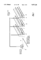
- FIGS. 12 and 13 illustrate a preferred arrangement for mounting the display tags 20 on a conventional shelf 24 which includes a depending rail 22 formed as an integral part of the shelf.
- An auxiliary rail 320 is snapped into the shelf rail 22 and extends continuously along the full length of the shelf for receiving both the display tags 20 and the conductor C.
- the auxiliary rail 320 is designed so that the display tag 20 and the conductor C may be snapped into place anywhere along the length of the rail.
- the insulated conductor C is mounted in two channels 321 and 322 formed near the top and bottom of the rear wall of the rail 320.
- the tag is received in a channel formed in the front side of the rail 320.
- the tag is recessed inside, and held in place by, a pair of flanges 323 and 324 so that the tag does not protrude from the rail.
- the upper flange 323 is flared outwardly at a slight angle so that it can be bent upwardly and outwardly for installation and removal of tags from the front of the rail.
- a pair of rearwardly projection flanges 325 and 326 hold the rail 320 in place on the shelf rail 22.
- the pick-up coil 110 is wound around the periphery of the tag housing 311 in a channel 328 formed in all four edges of the housing.
- the coil segments located in the top and bottom sections of the channel 328 are in close proximity to the two segments of the conductor C on the rear side of the rail 320.
- the coil is electromagnetically coupled to both segments of the conductor C.
- a single conductor C is snapped into the top channel 321 of the rail 320, spans the length of the store shelf, and then loops to the bottom channel 322 of the rail 320 and spans the length of the shelf rail again.
- FIG. 14 illustrates a display tag arrangement for products which are displayed on racks rather than shelves.
- This type of display rack is commonly used for products which are packaged in blister packages.
- the rack includes multiple rods 330, each of which supports multiple packages. A package can be removed from the rod by simply sliding the package off the forward end of the rod.
- a rail 320 is mounted directly above the rods 330, and contains a separate display tag 20 for each of the rods 330.
- the conductor C is fasten to the rear side of the rail 320 in the same manner described above in connection with FIGS. 12 and 13.
- FIG. 15 illustrates the use of the electronic display tag system of invention in a warehouse environment.
- Many warehouses contain numerous bins containing many different kinds of small articles which are difficult to identify from the markings on the articles themselves.
- FIG. 15 contains a diagrammatic illustration of four such bins 340.
- a rail 320 is mounted directly beneath each row of bins, and contains a separate display tag for each bin.
- the conductor C is mounted on the rear side of each of the rails 320.
Abstract
Description
Claims (28)
Priority Applications (9)
| Application Number | Priority Date | Filing Date | Title |
|---|---|---|---|
| US08/116,468 US5537126A (en) | 1993-09-03 | 1993-09-03 | Article-information display system using electronically controlled tags |
| AU76362/94A AU7636294A (en) | 1993-09-03 | 1994-08-24 | Article-information display system using electronically controlled tags |
| PCT/US1994/009486 WO1995006935A1 (en) | 1993-09-03 | 1994-08-24 | Article-information display system using electronically controlled tags |
| EP94926560A EP0715752A4 (en) | 1993-09-03 | 1994-08-24 | Article-information display system using electronically controlled tags |
| JP7508166A JPH09510304A (en) | 1993-09-03 | 1994-08-24 | Article information display system using electronically controlled tags |
| US08/398,297 US5736967A (en) | 1993-09-03 | 1995-03-03 | Article-information display system using electronically controlled tags |
| US08/944,308 US6181299B1 (en) | 1993-09-03 | 1997-10-06 | Power and communication system for electronic display tags |
| US09/309,082 US6266052B1 (en) | 1993-09-03 | 1999-05-10 | Power and information distribution system for article display or storage areas and related method |
| US09/309,119 US6271807B1 (en) | 1993-09-03 | 1999-05-10 | Method of initializing, controlling and updating electronic display tags and related controller therefor |
Applications Claiming Priority (1)
| Application Number | Priority Date | Filing Date | Title |
|---|---|---|---|
| US08/116,468 US5537126A (en) | 1993-09-03 | 1993-09-03 | Article-information display system using electronically controlled tags |
Related Child Applications (3)
| Application Number | Title | Priority Date | Filing Date |
|---|---|---|---|
| US30993494A Continuation-In-Part | 1993-09-03 | 1994-09-21 | |
| US08/398,297 Continuation-In-Part US5736967A (en) | 1993-09-03 | 1995-03-03 | Article-information display system using electronically controlled tags |
| US08/647,664 Continuation US6249263B1 (en) | 1993-09-03 | 1996-05-15 | Article-information display system using electronically controlled tags |
Publications (1)
| Publication Number | Publication Date |
|---|---|
| US5537126A true US5537126A (en) | 1996-07-16 |
Family
ID=22367370
Family Applications (1)
| Application Number | Title | Priority Date | Filing Date |
|---|---|---|---|
| US08/116,468 Expired - Lifetime US5537126A (en) | 1993-09-03 | 1993-09-03 | Article-information display system using electronically controlled tags |
Country Status (5)
| Country | Link |
|---|---|
| US (1) | US5537126A (en) |
| EP (1) | EP0715752A4 (en) |
| JP (1) | JPH09510304A (en) |
| AU (1) | AU7636294A (en) |
| WO (1) | WO1995006935A1 (en) |
Cited By (82)
| Publication number | Priority date | Publication date | Assignee | Title |
|---|---|---|---|---|
| US5736967A (en) * | 1993-09-03 | 1998-04-07 | Kayser Ventures, Ltd. | Article-information display system using electronically controlled tags |
| US5742237A (en) * | 1995-11-30 | 1998-04-21 | Lockheed Martin Corporation | Tag location monitor |
| US5764200A (en) * | 1992-06-22 | 1998-06-09 | Pricer Inc. | Connection using zebra strip |
| US5794211A (en) * | 1995-06-13 | 1998-08-11 | Ncr Corporation | EPL price verification system and method |
| US5822714A (en) * | 1997-03-05 | 1998-10-13 | International Business Machines Corporation | Data processing system and method for accessing a plurality of radio frequency identification tags |
| US5870067A (en) * | 1993-12-15 | 1999-02-09 | Bsc Developments Ltd. | Contactless data/power bus |
| US5870714A (en) * | 1997-05-02 | 1999-02-09 | Ncr Corporation | EPL scheduled price verification system and method |
| WO1999019829A1 (en) | 1997-10-10 | 1999-04-22 | Display Edge Technology, Ltd. | Article-information display system using electronically controlled tags |
| AU706480B2 (en) * | 1995-09-21 | 1999-06-17 | Ncr Corporation | Electronic price label replacement system and method |
| US5963133A (en) * | 1997-07-18 | 1999-10-05 | Monjo; Nicolas | Electronic tag |
| US5988498A (en) * | 1997-06-25 | 1999-11-23 | Ncr Corporation | Method of delaying availability of price changes to checkout terminals following EPL price changes |
| US6012040A (en) * | 1997-06-20 | 2000-01-04 | Ncr Corporation | EPL price change verification system and method |
| US6044358A (en) * | 1997-06-20 | 2000-03-28 | Ncr Corporation | System and method of determining price differences between price look-up files |
| US6043751A (en) * | 1995-07-17 | 2000-03-28 | Ncr Corporation | Method for detecting and reporting failures in EPL systems |
| WO2000067240A2 (en) * | 1999-04-30 | 2000-11-09 | Display Edge Technology Ltd. | Electronic tags incorporating a customer attracting annunciator for use in electronic product information display systems |
| US6181299B1 (en) * | 1993-09-03 | 2001-01-30 | Display Edge Technology, Ltd. | Power and communication system for electronic display tags |
| US6209831B1 (en) | 1999-02-24 | 2001-04-03 | Display Edge Technology Ltd. | Product support hook for use in electronic product information display system |
| US6307919B1 (en) * | 1998-05-29 | 2001-10-23 | Yehuda Yoked | Remote controlled electronic price tag |
| US6329139B1 (en) | 1995-04-25 | 2001-12-11 | Discovery Partners International | Automated sorting system for matrices with memory |
| US6392544B1 (en) * | 2000-09-25 | 2002-05-21 | Motorola, Inc. | Method and apparatus for selectively activating radio frequency identification tags that are in close proximity |
| US6409132B2 (en) | 1999-04-30 | 2002-06-25 | Display Edge Technology, Ltd. | Attachment bracket for a rail |
| US20020109593A1 (en) * | 2001-02-15 | 2002-08-15 | Swartzel Stanley J. | Electronic display system tag, related interface protocal and display methods |
| US20020167500A1 (en) * | 1998-09-11 | 2002-11-14 | Visible Techknowledgy, Llc | Smart electronic label employing electronic ink |
| US20030023505A1 (en) * | 2001-02-28 | 2003-01-30 | Eglen Jan Alan | Digital online exchange |
| US6516041B1 (en) * | 1999-10-07 | 2003-02-04 | Westinghouse Electric Co. Llc | Method and apparatus to eliminate confirmation switches and channel demultiplexer from soft control man-machine interface (MMI) |
| US6552663B2 (en) | 2000-02-16 | 2003-04-22 | Display Edge Technology, Ltd. | Product information display system with expanded retail display functions |
| FR2834857A1 (en) * | 2002-01-16 | 2003-07-18 | Gemplus Card Int | TRANSPONDER EQUIPPED WITH A CENTRAL CIRCUIT AND AT LEAST ONE PERIPHERAL CIRCUIT AND METHOD FOR EXCHANGING DATA BETWEEN SAID CIRCUITS VIA A STATION IN INDUCTIVE COUPLING WITH THE TRANSPONDER |
| US6622410B2 (en) | 1998-02-20 | 2003-09-23 | Illinois Tool Works Inc. | Attachment bracket for a shelf-edge display system |
| US20030233288A1 (en) * | 2002-06-17 | 2003-12-18 | Sweeney William R. | System for coupling package displays to remote power source |
| US20040012485A1 (en) * | 2000-07-07 | 2004-01-22 | David Sundqvist | Price label system |
| US20040012196A1 (en) * | 2000-07-07 | 2004-01-22 | David Sundqvist | Price label communication system |
| US6715676B1 (en) | 2000-11-28 | 2004-04-06 | Ncr Corporation | Methods and apparatus for an electronic price label system |
| US20040084525A1 (en) * | 2002-10-30 | 2004-05-06 | Barrett Kreiner | System for monitoring and tracking objects |
| US20040085207A1 (en) * | 2002-10-30 | 2004-05-06 | Barrett Kreiner | Method for monitoring and tracking objects |
| US6753830B2 (en) | 1998-09-11 | 2004-06-22 | Visible Tech-Knowledgy, Inc. | Smart electronic label employing electronic ink |
| US20040207512A1 (en) * | 2000-12-11 | 2004-10-21 | Bastian William A. | Inventory system with image display |
| US6864792B2 (en) * | 2002-09-06 | 2005-03-08 | Sensormatic Electronics Corporation | Portable electronic security key for electronic article surveillance device |
| US20050140498A1 (en) * | 2000-12-11 | 2005-06-30 | Bastian William A.Ii | Inventory system with barcode display |
| US6924781B1 (en) | 1998-09-11 | 2005-08-02 | Visible Tech-Knowledgy, Inc. | Smart electronic label employing electronic ink |
| US20050200478A1 (en) * | 2002-10-30 | 2005-09-15 | Bellsouth Intellectual Property Corporation | Instantaneous mobile access to all pertinent life events |
| US20050200559A1 (en) * | 2004-02-24 | 2005-09-15 | Fumio Koyama | Information display and information display system |
| US20050218218A1 (en) * | 2004-03-31 | 2005-10-06 | Karl Koster | Systems and methods for an electronic programmable merchandise tag |
| US20050234785A1 (en) * | 2004-04-13 | 2005-10-20 | Burman Robert F | Electronic shipping label with updateable visual display |
| US7026913B2 (en) | 1999-11-30 | 2006-04-11 | Ncr Corporation | Methods and apparatus for self-diagnosing electronic price labels |
| US20060100967A1 (en) * | 2002-08-28 | 2006-05-11 | Salvatore Grimaldi | Electronic pricing system, device and method |
| US7075529B1 (en) | 1998-09-25 | 2006-07-11 | Ulead Systems, Inc. | Method of processing diverse three-dimensional graphic objects |
| US20060176239A1 (en) * | 2005-02-04 | 2006-08-10 | Philip Morris Usa Inc. | Display management system |
| US20060187040A1 (en) * | 2005-02-04 | 2006-08-24 | Philip Morris Usa Inc. | Controllable RFID card |
| US20070019576A1 (en) * | 2005-07-08 | 2007-01-25 | Hansder Engineering Co., Ltd. | Network computer having power frequency carrier |
| US20070115954A1 (en) * | 2005-10-18 | 2007-05-24 | Sunplus Technology Co., Ltd. | Transmitting circuit, receiving circuit, interface switching module and interface switching method for SATA and SAS interfaces |
| US20070115126A1 (en) * | 2005-11-22 | 2007-05-24 | Ncr Corporation | Methods and apparatus for identifying electronic shelf labels with which communication has been lost |
| US20070291277A1 (en) * | 2006-06-20 | 2007-12-20 | Everett Matthew J | Spectral domain optical coherence tomography system |
| US20090319078A1 (en) * | 2008-06-23 | 2009-12-24 | United Parcel Services Of America, Inc. | Method for shipping an item using an electronic envelope |
| US20090314835A1 (en) * | 2008-06-23 | 2009-12-24 | United Parcel Services Of America, Inc. | System for shipping an item using an electronic envelope |
| US20100117933A1 (en) * | 1998-04-30 | 2010-05-13 | David Gothard | High resolution computer operated digital display system |
| US7791489B2 (en) | 2003-09-03 | 2010-09-07 | Metrologic Instruments, Inc. | Electronic-ink based RFID tag for attachment to a consumer item and displaying graphical indicia indicating whether or not said consumer items has been read and its integrated RFID module has been activated or deactivated |
| US20100253521A1 (en) * | 2009-04-03 | 2010-10-07 | Guardtracker Innovations, Llc | Methods, Systems and Articles of Manufacture for Monitoring Subjects within a Facility |
| US20100277335A1 (en) * | 2007-10-05 | 2010-11-04 | Kaj Makela | Presentation of Visual Information |
| US20100309208A1 (en) * | 1998-04-30 | 2010-12-09 | Dave Gothard | Remote Control Electronic Display System |
| US20110095864A1 (en) * | 2008-01-18 | 2011-04-28 | Roche Molecular Systems, Inc. | Laboratory Device, Laboratory Rack Assembly and Method for Coupling an RFID Chip |
| US20110154260A1 (en) * | 2009-12-17 | 2011-06-23 | Motorola Inc | Method and apparatus for displaying information in an electronic device |
| US20110153112A1 (en) * | 2007-08-10 | 2011-06-23 | Inta Holdings Pty Limited | Electrical tagging device |
| US20110240731A1 (en) * | 2010-03-30 | 2011-10-06 | Samsung Electro-Mechanics Co., Ltd. | Electronic shelf label system, method of synchronizing electronic shelf label tag with product, and method of updating product information of the same |
| US20120013467A1 (en) * | 2010-07-15 | 2012-01-19 | Samsung Electro-Mechanics Co., Ltd. | Electronic shelf label system and method for driving the same |
| US20120094606A1 (en) * | 2009-08-19 | 2012-04-19 | Nec Corporation | Communication device, communication system, and communication method |
| US8234507B2 (en) | 2009-01-13 | 2012-07-31 | Metrologic Instruments, Inc. | Electronic-ink display device employing a power switching mechanism automatically responsive to predefined states of device configuration |
| US8457013B2 (en) | 2009-01-13 | 2013-06-04 | Metrologic Instruments, Inc. | Wireless dual-function network device dynamically switching and reconfiguring from a wireless network router state of operation into a wireless network coordinator state of operation in a wireless communication network |
| US8762212B2 (en) | 1995-07-31 | 2014-06-24 | Information Planning & Management Service, Inc. | Electronic product information display system |
| US20140268949A1 (en) * | 2013-03-15 | 2014-09-18 | Tagnetics, Inc. | Apparatus and system of power conversion |
| US8893977B2 (en) | 2010-04-08 | 2014-11-25 | Access Business Group International Llc | Point of sale inductive systems and methods |
| US8910801B2 (en) | 2012-06-21 | 2014-12-16 | L & P Property Management Company | Inductively coupled product positioning system |
| US9022637B2 (en) | 2013-04-30 | 2015-05-05 | Tagnetics, Inc. | Lighted mounting apparatus |
| US20150196920A1 (en) * | 2014-01-14 | 2015-07-16 | Biohitech America | Network connected weight tracking system for a waste disposal machine |
| WO2016011178A1 (en) * | 2014-07-15 | 2016-01-21 | Tagnetics, Inc. | Advertising beacon for retail environments |
| US9251727B2 (en) | 2012-06-21 | 2016-02-02 | L&P Property Management Company | Inductively coupled product display |
| US9275361B2 (en) | 2013-01-11 | 2016-03-01 | Tagnetics, Inc. | Out of stock sensor |
| US9367851B2 (en) | 2009-09-17 | 2016-06-14 | Information Planning & Management Service, Inc. | System and method for managing compliance with retail display regulations across a plurality of jurisdictions |
| US9364100B2 (en) | 2012-06-21 | 2016-06-14 | L & P Property Management Company | Inductively coupled shelving system |
| US9474177B2 (en) | 2012-04-26 | 2016-10-18 | Teraoka Seiko Co., Ltd. | Wireless display mount, wireless display mount apparatus, and wireless display system |
| US10312731B2 (en) | 2014-04-24 | 2019-06-04 | Westrock Shared Services, Llc | Powered shelf system for inductively powering electrical components of consumer product packages |
| US11107136B2 (en) | 2016-10-21 | 2021-08-31 | Brian Conville | Management of products and dynamic price display system |
| CN113673659A (en) * | 2021-08-09 | 2021-11-19 | 苏州浩创信息科技有限公司 | Serial electronic label system and information processing method thereof |
Families Citing this family (5)
| Publication number | Priority date | Publication date | Assignee | Title |
|---|---|---|---|---|
| US6044359A (en) * | 1997-11-13 | 2000-03-28 | Ncr Corporation | Method of minimizing power consumption within an electronic price label |
| JP2005258572A (en) * | 2004-03-09 | 2005-09-22 | Hideo Shinji | Electronic tag system |
| FR2954548B1 (en) * | 2009-12-18 | 2013-10-04 | Schneider Electric Ind Sas | MAN-MACHINE DIALOGUE SYSTEM |
| JP5987453B2 (en) * | 2012-04-26 | 2016-09-07 | 株式会社寺岡精工 | Wireless display mounting device, wireless display mounting device, and wireless display system |
| JP6908844B2 (en) * | 2017-07-28 | 2021-07-28 | 富士通セミコンダクターメモリソリューション株式会社 | Semiconductor storage device with wireless communication function and application control method |
Citations (21)
| Publication number | Priority date | Publication date | Assignee | Title |
|---|---|---|---|---|
| US3086308A (en) * | 1959-06-29 | 1963-04-23 | Westlake G Ternouth | Shelf-edge sign |
| US3256512A (en) * | 1962-06-05 | 1966-06-14 | North Electric Co | Remote sign control system |
| US3622992A (en) * | 1969-10-15 | 1971-11-23 | Honeywell Inc | Supervision and control apparatus with selective display |
| US4002886A (en) * | 1975-06-20 | 1977-01-11 | Ronald Murl Sundelin | Electronic price display unit |
| US4500880A (en) * | 1981-07-06 | 1985-02-19 | Motorola, Inc. | Real time, computer-driven retail pricing display system |
| US4521677A (en) * | 1983-12-02 | 1985-06-04 | Sarwin Herbert S | Product control system for supermarkets and the like |
| US4525713A (en) * | 1983-03-01 | 1985-06-25 | Lockheed Electronics Co., Inc. | Electronic tag identification system |
| US4603495A (en) * | 1984-09-19 | 1986-08-05 | Stevens John K | Alphanumeric display modules |
| US4654514A (en) * | 1984-09-10 | 1987-03-31 | Texas Instruments Incorporated | Product information system using hand-held unit with code reader |
| US4702558A (en) * | 1983-09-14 | 1987-10-27 | The Victoria University Of Manchester | Liquid crystal information storage device |
| US4745404A (en) * | 1985-11-23 | 1988-05-17 | Edding Ag | Display device for planning purposes |
| WO1988006773A1 (en) * | 1987-02-26 | 1988-09-07 | Gabriel Ordonez | Retail display system |
| US4821291A (en) * | 1986-09-22 | 1989-04-11 | Stevens John K | Improvements in or relating to signal communication systems |
| US4937586A (en) * | 1986-09-22 | 1990-06-26 | Stevens John K | Radio broadcast communication systems with multiple loop antennas |
| US4962466A (en) * | 1987-03-27 | 1990-10-09 | Viscom Systems, Inc. | Electronic product information display system |
| WO1990014630A1 (en) * | 1989-05-16 | 1990-11-29 | Rest Manufacturing, Inc. | Remote electronic information display system |
| US5019811A (en) * | 1984-10-15 | 1991-05-28 | Unigrafic Ag | Device for marking edges of shelves |
| US5111196A (en) * | 1987-03-23 | 1992-05-05 | Esl, Inc. | Electronic information display module and connector therefor |
| US5172314A (en) * | 1991-05-03 | 1992-12-15 | Electronic Retailing Systems International | Apparatus for communicating price changes including printer and display devices |
| US5198644A (en) * | 1989-05-05 | 1993-03-30 | Diablo Research Corporation | System for display of prices and related method |
| US5241467A (en) * | 1992-04-30 | 1993-08-31 | Ers Associates Limited Partnership | Space management system |
Family Cites Families (9)
| Publication number | Priority date | Publication date | Assignee | Title |
|---|---|---|---|---|
| AU525251B2 (en) * | 1978-06-02 | 1982-10-28 | Amalgamated Wireless (Australasia) Limited | Identification system |
| US4785195A (en) * | 1987-06-01 | 1988-11-15 | University Of Tennessee Research Corporation | Power line communication |
| SE466773B (en) * | 1989-12-01 | 1992-03-30 | Roland Braennstroem | ELECTRONIC PRICE INFORMATION SYSTEM |
| FR2657479B1 (en) * | 1990-01-19 | 1994-07-08 | Bertin & Cie | DEVICE FOR BIDIRECTIONAL TRANSMISSION OF INFORMATION TO A RECEIVER POWERED BY THE TRANSMITTER. |
| FR2658645B1 (en) * | 1990-02-16 | 1994-10-07 | Sitour Electronic Systems | INSTALLATION COMPRISING A SET OF REMOTE CONTROL DISPLAY MODULES. |
| WO1992008213A1 (en) * | 1990-10-30 | 1992-05-14 | Elis Identifikationssysteme Gesellschaft M.B.H | Transmission system |
| EP0497533A3 (en) * | 1991-01-28 | 1995-04-05 | NCR International, Inc. | Electronic price display apparatus |
| JP3442076B2 (en) * | 1991-12-04 | 2003-09-02 | シチズン時計株式会社 | Data carrier |
| GB9309246D0 (en) * | 1993-05-05 | 1993-06-16 | Esselte Meto Int Gmbh | Rechargeable shelf edge tag |
-
1993
- 1993-09-03 US US08/116,468 patent/US5537126A/en not_active Expired - Lifetime
-
1994
- 1994-08-24 AU AU76362/94A patent/AU7636294A/en not_active Abandoned
- 1994-08-24 WO PCT/US1994/009486 patent/WO1995006935A1/en not_active Application Discontinuation
- 1994-08-24 EP EP94926560A patent/EP0715752A4/en not_active Withdrawn
- 1994-08-24 JP JP7508166A patent/JPH09510304A/en active Pending
Patent Citations (21)
| Publication number | Priority date | Publication date | Assignee | Title |
|---|---|---|---|---|
| US3086308A (en) * | 1959-06-29 | 1963-04-23 | Westlake G Ternouth | Shelf-edge sign |
| US3256512A (en) * | 1962-06-05 | 1966-06-14 | North Electric Co | Remote sign control system |
| US3622992A (en) * | 1969-10-15 | 1971-11-23 | Honeywell Inc | Supervision and control apparatus with selective display |
| US4002886A (en) * | 1975-06-20 | 1977-01-11 | Ronald Murl Sundelin | Electronic price display unit |
| US4500880A (en) * | 1981-07-06 | 1985-02-19 | Motorola, Inc. | Real time, computer-driven retail pricing display system |
| US4525713A (en) * | 1983-03-01 | 1985-06-25 | Lockheed Electronics Co., Inc. | Electronic tag identification system |
| US4702558A (en) * | 1983-09-14 | 1987-10-27 | The Victoria University Of Manchester | Liquid crystal information storage device |
| US4521677A (en) * | 1983-12-02 | 1985-06-04 | Sarwin Herbert S | Product control system for supermarkets and the like |
| US4654514A (en) * | 1984-09-10 | 1987-03-31 | Texas Instruments Incorporated | Product information system using hand-held unit with code reader |
| US4603495A (en) * | 1984-09-19 | 1986-08-05 | Stevens John K | Alphanumeric display modules |
| US5019811A (en) * | 1984-10-15 | 1991-05-28 | Unigrafic Ag | Device for marking edges of shelves |
| US4745404A (en) * | 1985-11-23 | 1988-05-17 | Edding Ag | Display device for planning purposes |
| US4821291A (en) * | 1986-09-22 | 1989-04-11 | Stevens John K | Improvements in or relating to signal communication systems |
| US4937586A (en) * | 1986-09-22 | 1990-06-26 | Stevens John K | Radio broadcast communication systems with multiple loop antennas |
| WO1988006773A1 (en) * | 1987-02-26 | 1988-09-07 | Gabriel Ordonez | Retail display system |
| US5111196A (en) * | 1987-03-23 | 1992-05-05 | Esl, Inc. | Electronic information display module and connector therefor |
| US4962466A (en) * | 1987-03-27 | 1990-10-09 | Viscom Systems, Inc. | Electronic product information display system |
| US5198644A (en) * | 1989-05-05 | 1993-03-30 | Diablo Research Corporation | System for display of prices and related method |
| WO1990014630A1 (en) * | 1989-05-16 | 1990-11-29 | Rest Manufacturing, Inc. | Remote electronic information display system |
| US5172314A (en) * | 1991-05-03 | 1992-12-15 | Electronic Retailing Systems International | Apparatus for communicating price changes including printer and display devices |
| US5241467A (en) * | 1992-04-30 | 1993-08-31 | Ers Associates Limited Partnership | Space management system |
Cited By (183)
| Publication number | Priority date | Publication date | Assignee | Title |
|---|---|---|---|---|
| US5764200A (en) * | 1992-06-22 | 1998-06-09 | Pricer Inc. | Connection using zebra strip |
| US6181299B1 (en) * | 1993-09-03 | 2001-01-30 | Display Edge Technology, Ltd. | Power and communication system for electronic display tags |
| US5736967A (en) * | 1993-09-03 | 1998-04-07 | Kayser Ventures, Ltd. | Article-information display system using electronically controlled tags |
| US5870067A (en) * | 1993-12-15 | 1999-02-09 | Bsc Developments Ltd. | Contactless data/power bus |
| US6329139B1 (en) | 1995-04-25 | 2001-12-11 | Discovery Partners International | Automated sorting system for matrices with memory |
| US5794211A (en) * | 1995-06-13 | 1998-08-11 | Ncr Corporation | EPL price verification system and method |
| US6073843A (en) * | 1995-06-13 | 2000-06-13 | Ncr Corporation | EPL price verification system and method |
| US6043751A (en) * | 1995-07-17 | 2000-03-28 | Ncr Corporation | Method for detecting and reporting failures in EPL systems |
| US8762212B2 (en) | 1995-07-31 | 2014-06-24 | Information Planning & Management Service, Inc. | Electronic product information display system |
| US8910864B2 (en) | 1995-07-31 | 2014-12-16 | Information Planning & Management Service, Inc. | Electronic product information display system |
| AU706480B2 (en) * | 1995-09-21 | 1999-06-17 | Ncr Corporation | Electronic price label replacement system and method |
| US5742237A (en) * | 1995-11-30 | 1998-04-21 | Lockheed Martin Corporation | Tag location monitor |
| US5822714A (en) * | 1997-03-05 | 1998-10-13 | International Business Machines Corporation | Data processing system and method for accessing a plurality of radio frequency identification tags |
| US5870714A (en) * | 1997-05-02 | 1999-02-09 | Ncr Corporation | EPL scheduled price verification system and method |
| US6044358A (en) * | 1997-06-20 | 2000-03-28 | Ncr Corporation | System and method of determining price differences between price look-up files |
| US6012040A (en) * | 1997-06-20 | 2000-01-04 | Ncr Corporation | EPL price change verification system and method |
| US5988498A (en) * | 1997-06-25 | 1999-11-23 | Ncr Corporation | Method of delaying availability of price changes to checkout terminals following EPL price changes |
| US5963133A (en) * | 1997-07-18 | 1999-10-05 | Monjo; Nicolas | Electronic tag |
| EP1021789A1 (en) * | 1997-10-10 | 2000-07-26 | Display Edge Technology, Ltd. | Article-information display system using electronically controlled tags |
| EP1021789A4 (en) * | 1997-10-10 | 2005-04-27 | Display Edge Technology Ltd | Article-information display system using electronically controlled tags |
| WO1999019829A1 (en) | 1997-10-10 | 1999-04-22 | Display Edge Technology, Ltd. | Article-information display system using electronically controlled tags |
| US6622410B2 (en) | 1998-02-20 | 2003-09-23 | Illinois Tool Works Inc. | Attachment bracket for a shelf-edge display system |
| US20100117933A1 (en) * | 1998-04-30 | 2010-05-13 | David Gothard | High resolution computer operated digital display system |
| US20100309208A1 (en) * | 1998-04-30 | 2010-12-09 | Dave Gothard | Remote Control Electronic Display System |
| US8330613B2 (en) | 1998-04-30 | 2012-12-11 | Locke International Teast | Remote control electronic display system |
| US6307919B1 (en) * | 1998-05-29 | 2001-10-23 | Yehuda Yoked | Remote controlled electronic price tag |
| US7703678B2 (en) | 1998-09-11 | 2010-04-27 | Metrologic Instruments, Inc. | Electronic monetary instrument employing an electronic-ink layer for visually displaying the monetary value thereof in a particular currency |
| US7753277B2 (en) | 1998-09-11 | 2010-07-13 | Metrologic Instruments, Inc. | User-operable actuation device employing an updateable electronic-ink display label |
| US20090015427A1 (en) * | 1998-09-11 | 2009-01-15 | Metrologic Instruments, Inc. | Electronic-ink based multi-purpose board game employing a game board and game pieces with an electronic-ink display structure |
| US20020167500A1 (en) * | 1998-09-11 | 2002-11-14 | Visible Techknowledgy, Llc | Smart electronic label employing electronic ink |
| US8054218B2 (en) | 1998-09-11 | 2011-11-08 | Metrologic Instruments, Inc. | Remotely-alterable electronic-ink based display device employing an integrated circuit structure having a GPS signal receiver and programmed processor for locally determining display device position and transmitting determined position information to a remote activator module |
| US20090014534A1 (en) * | 1998-09-11 | 2009-01-15 | Metrologic Instruments, Inc. | Remotely-alterable flexible electronic display device employing an electronic-ink layer integrated within a stacked-layer architecture |
| US7946489B2 (en) | 1998-09-11 | 2011-05-24 | Metrologic Instruments, Inc. | Electronic-ink based writing/drawing and display device employing an activator module mounted beneath the surface of an electronic-ink display structure |
| US20090014541A1 (en) * | 1998-09-11 | 2009-01-15 | Metrologic Instruments, Inc. | User-operable actuation device employing an updateable electronic-ink display label |
| US20090014512A1 (en) * | 1998-09-11 | 2009-01-15 | Metrologic Instruments, Inc. | Electronic tagging system for tagging a plurality of luggage items transported through a transportation system, using electronic-ink display tags for displaying real-time information regarding said luggage items, and remotely programmable by activator modules installed throughout said transportion system |
| US20090014542A1 (en) * | 1998-09-11 | 2009-01-15 | Metrologic Instruments, Inc. | Card-sized electronic data storage device employing an electronic-ink layer for displaying graphical indicia |
| US7918395B2 (en) | 1998-09-11 | 2011-04-05 | Metrologic Instruments, Inc. | Electronic product identification and price display system employing electronic-ink display labels having a stacked architecture for visually displaying the price and/or promotional information for said consumer product, remotely updated by one or more remote activator modules installed within the retail environment |
| US7918396B2 (en) | 1998-09-11 | 2011-04-05 | Metrologic Instruments, Inc. | Electronic-ink based information organizing device employing an activator module mounted beneath the surface of an electronic-ink display structure |
| US6753830B2 (en) | 1998-09-11 | 2004-06-22 | Visible Tech-Knowledgy, Inc. | Smart electronic label employing electronic ink |
| US20090014535A1 (en) * | 1998-09-11 | 2009-01-15 | Metrologic Instruments, Inc. | Remotely-alterable electronic display label employing an electronic ink layer integrated within a stacked-layer architecture employing an antenna layer and an integrated circuit layer supporting an on-board battery power component, and a programmed processor for determining graphical indicia to be displayed by said electronic ink layer in response to electromagnetic signals received from said antenna |
| US7913908B2 (en) | 1998-09-11 | 2011-03-29 | Metrologic Instruments, Inc. | Electronic-ink based display tagging system employing a plurality electronic-ink display tags having a stacked architecture and being powered and programmed by a portable tag activation module |
| US7891569B2 (en) | 1998-09-11 | 2011-02-22 | Metrologic Instruments, Inc. | Electronic-ink based display device employing an electronic-ink layer integrated within a stacked architecture |
| US7871001B2 (en) | 1998-09-11 | 2011-01-18 | Metrologic Instruments, Inc. | Remotely-alterable electronic-ink based display device employing an electronic-ink layer integrated within a stacked architecture |
| US20090014537A1 (en) * | 1998-09-11 | 2009-01-15 | Metrologic Instruments, Inc. | Electronic shipping container labeling system for labeling a plurality of shipping containers transported through a shipping system, using electronic-ink shipping labels displaying information regarding said shipping containers, and remotely updated by one or more activator modules |
| US20090014533A1 (en) * | 1998-09-11 | 2009-01-15 | Metrologic Instruments, Inc. | Remotely-alterable electronic display device employing an electronic-ink layer integrated within a stacked-layer architecture |
| US7815116B2 (en) | 1998-09-11 | 2010-10-19 | Metrologic Instruments, Inc. | Electronic tagging system for tagging a plurality of luggage items transported through a transportation system, using electronic-ink display tags for displaying real-time information regarding said luggage items, and remotely programmable by activator modules installed throughout said transportion system |
| US20090014538A1 (en) * | 1998-09-11 | 2009-01-15 | Metrologic Instruments, Inc. | Electronic monetary instrument employing an electronic-ink layer for visually displaying the monetary value thereof in a particular currency |
| US6924781B1 (en) | 1998-09-11 | 2005-08-02 | Visible Tech-Knowledgy, Inc. | Smart electronic label employing electronic ink |
| US7798404B2 (en) | 1998-09-11 | 2010-09-21 | Metrologic Instruments, Inc. | Electronic admission pass system employing a plurality of updateable electronic-ink admission passes and one or more activator modules |
| US7784701B2 (en) | 1998-09-11 | 2010-08-31 | Metrologic Instruments, Inc. | Electronic product price display system for installation in a retail environment and employing a plurality of electronic-ink display labels associated with a plurality of consumer products, for displaying price and/or promotional information remotely programmed using one or more activator modules installed within said retail environment |
| US7766238B2 (en) | 1998-09-11 | 2010-08-03 | Metrologic Instruments, Inc. | Electronic shipping container labeling system for labeling a plurality of shipping containers transported through a shipping system, using electronic-ink shipping labels displaying information regarding said shipping containers, and remotely updated by one or more activator modules |
| US7762461B2 (en) | 1998-09-11 | 2010-07-27 | Metrologic Instruments, Inc. | Remotely-alterable wireless electronic display device employing an electronic ink layer integrated within a stacked-layer architecture, including an activation grid matrix layer and transmitting and receiving antenna layers |
| US7762462B2 (en) | 1998-09-11 | 2010-07-27 | Metrologic Instruments, Inc. | Electronic information display system employing a plurality of electronic-ink display labels associated with a plurality of manufactured items for displaying information which changes as the manufactured items move through wholesale/retail distribution channels |
| US7757954B2 (en) | 1998-09-11 | 2010-07-20 | Metrologic Instruments, Inc. | Remotely-alterable flexible electronic display device employing an electronic-ink layer integrated within a stacked-layer architecture |
| US20090014529A1 (en) * | 1998-09-11 | 2009-01-15 | Metrologic Instruments, Inc. | Remotely-alterable wireless electronic dislay device employing an electronic ink layer integrated within a stacked-layer architecture, including an activation grid matrix layer and transmitting and receiving antenna layers |
| US20080314992A1 (en) * | 1998-09-11 | 2008-12-25 | Metrologic Instruments, Inc. | Digital information recording media system including a digital information recording media device with an electronic-ink display label for displaying information related to said digital information recording media device and/or digital information recorded thereon |
| US7753276B2 (en) | 1998-09-11 | 2010-07-13 | Metrologic Instruments, Inc. | Electronic-ink based multi-purpose board game employing a game board and game pieces with an electronic-ink display structure |
| US20080297442A1 (en) * | 1998-09-11 | 2008-12-04 | Metrologic Instruments, Inc. | Electronic-ink based display tagging system employing a plurality of programmable electronic-ink display tags having a stacked architecture, and portable tag activation module for programming the same |
| US20090014528A1 (en) * | 1998-09-11 | 2009-01-15 | Metrologic Instruments, Inc. | Remotely-alterable radio-frequency (RF) powered electronic display label employing an electronic ink layer integrated within a stacked-layer architecture |
| US7748627B2 (en) | 1998-09-11 | 2010-07-06 | Metrologic Instruments, Inc. | Card-sized electronic data storage device employing an electronic-ink layer for displaying graphical indicia |
| US7748626B2 (en) | 1998-09-11 | 2010-07-06 | Metrologic Instruments, Inc. | Electronic menu display system employing a plurality of portable menus, each including an electronic-ink display label for displaying information updated by one or more activator modules within the restaurant |
| US7743987B2 (en) | 1998-09-11 | 2010-06-29 | Metrologic Instruments, Inc. | Electronic-ink based label system employing a plurality of remote activator modules in communication with a plurality of remotely-updateable electronic-ink display labels each assigned unique encryption keys for allowing only a subset of said labels to receive a broadcasted message from a common encrypted message broadcast signal |
| US7735736B2 (en) | 1998-09-11 | 2010-06-15 | Metrologic Instruments, Inc. | Remotely-alterable electronic display device employing an electronic-ink layer integrated within a stacked-layer architecture |
| US7735735B2 (en) | 1998-09-11 | 2010-06-15 | Metrologic Instruments, Inc. | Electronic-ink based display system employing a plurality of RF-based activator modules in wireless communication with a plurality of remotely-updateable electronic display devices, each employing an electronic ink layer integrated within a stacked architecture |
| US20070024551A1 (en) * | 1998-09-11 | 2007-02-01 | Alexander Gelbman | Smart electronic label employing electronic ink |
| US20090014530A1 (en) * | 1998-09-11 | 2009-01-15 | Metrologic Instruments, Inc. | Electronic-ink based display device employing an electronic-ink layer integrated within a stacked architecture |
| US20090014536A1 (en) * | 1998-09-11 | 2009-01-15 | Metrologic Instruments, Inc. | Consumer product package bearing a remotely-alterable Radio-Frequency (RF) powered eletronic display label employing an electronic ink layer integrated within a stacked-layer architecture |
| US7677454B2 (en) | 1998-09-11 | 2010-03-16 | Metrologic Instruments, Inc. | Digital information recording media system including a digital information recording media device with an electronic-ink display label for displaying information related to said digital information recording media device and/or digital information recorded thereon |
| US7673800B2 (en) | 1998-09-11 | 2010-03-09 | Metrologic Instruments, Inc. | Remotely-alterable radio-frequency (RF) powered electronic display label employing an electronic ink layer integrated within a stacked-layer architecture |
| US7669768B2 (en) | 1998-09-11 | 2010-03-02 | Metrologic Instruments, Inc. | Remotely-alterable electronic display label employing an electronic ink layer integrated within a stacked-layer architecture employing an antenna layer and an integrated circuit layer supporting an on-board battery power component, and a programmed processor for determining graphical indicia to be displayed by said electronic ink layer in response to electromagnetic signals received from said antenna |
| US7658329B2 (en) | 1998-09-11 | 2010-02-09 | Metrologic Instruments, Inc. | Consumer product package bearing a remotely-alterable radio-frequency (RF) powered electronic display label employing an electronic ink layer integrated within a stacked-layer architecture |
| US20090026273A1 (en) * | 1998-09-11 | 2009-01-29 | Metrologic Instruments, Inc. | Electronic menu display system employing a plurality of portable menus, each including an electronic-ink display label for displaying information updated by one or more activator modules within the restaurant |
| US20090020605A1 (en) * | 1998-09-11 | 2009-01-22 | Metrologic Instruments, Inc. | Electronic admission pass system employing a plurality of updateable electronic-ink admission passes and one or more activator modules |
| US20090020614A1 (en) * | 1998-09-11 | 2009-01-22 | Metrologic Instruments, Inc. | Electronic information display system employing a plurality of electronic-ink display labels associated with a plurality of manufactured items for displaying information which changes as the manufactured items move through wholesale/retail distribution channels |
| US7075529B1 (en) | 1998-09-25 | 2006-07-11 | Ulead Systems, Inc. | Method of processing diverse three-dimensional graphic objects |
| US6209831B1 (en) | 1999-02-24 | 2001-04-03 | Display Edge Technology Ltd. | Product support hook for use in electronic product information display system |
| US6798389B1 (en) * | 1999-04-30 | 2004-09-28 | Illinois Tool Works Inc. | Electronic tags incorporating a customer attracting annunciator for use in electronic product information display systems |
| WO2000067240A2 (en) * | 1999-04-30 | 2000-11-09 | Display Edge Technology Ltd. | Electronic tags incorporating a customer attracting annunciator for use in electronic product information display systems |
| US6409132B2 (en) | 1999-04-30 | 2002-06-25 | Display Edge Technology, Ltd. | Attachment bracket for a rail |
| WO2000067240A3 (en) * | 1999-04-30 | 2001-02-01 | Display Edge Technology Ltd | Electronic tags incorporating a customer attracting annunciator for use in electronic product information display systems |
| US6516041B1 (en) * | 1999-10-07 | 2003-02-04 | Westinghouse Electric Co. Llc | Method and apparatus to eliminate confirmation switches and channel demultiplexer from soft control man-machine interface (MMI) |
| US7026913B2 (en) | 1999-11-30 | 2006-04-11 | Ncr Corporation | Methods and apparatus for self-diagnosing electronic price labels |
| US6552663B2 (en) | 2000-02-16 | 2003-04-22 | Display Edge Technology, Ltd. | Product information display system with expanded retail display functions |
| US20040012196A1 (en) * | 2000-07-07 | 2004-01-22 | David Sundqvist | Price label communication system |
| US20040012485A1 (en) * | 2000-07-07 | 2004-01-22 | David Sundqvist | Price label system |
| US7005962B2 (en) * | 2000-07-07 | 2006-02-28 | Pricer Ab | Price label communication system |
| US6392544B1 (en) * | 2000-09-25 | 2002-05-21 | Motorola, Inc. | Method and apparatus for selectively activating radio frequency identification tags that are in close proximity |
| US6715676B1 (en) | 2000-11-28 | 2004-04-06 | Ncr Corporation | Methods and apparatus for an electronic price label system |
| US20050140498A1 (en) * | 2000-12-11 | 2005-06-30 | Bastian William A.Ii | Inventory system with barcode display |
| US7084738B2 (en) | 2000-12-11 | 2006-08-01 | Asap Automation, Llc | Inventory system with image display |
| US7262685B2 (en) | 2000-12-11 | 2007-08-28 | Asap Automation, Llc | Inventory system with barcode display |
| US20040207512A1 (en) * | 2000-12-11 | 2004-10-21 | Bastian William A. | Inventory system with image display |
| US6844821B2 (en) | 2001-02-15 | 2005-01-18 | Illinois Tool Works Inc. | Electronic display system tag, related interface protocal and display methods |
| US20020109593A1 (en) * | 2001-02-15 | 2002-08-15 | Swartzel Stanley J. | Electronic display system tag, related interface protocal and display methods |
| US7080030B2 (en) | 2001-02-28 | 2006-07-18 | Digonex Technologies, Inc. | Digital online exchange |
| US20030023505A1 (en) * | 2001-02-28 | 2003-01-30 | Eglen Jan Alan | Digital online exchange |
| US20060208074A1 (en) * | 2001-02-28 | 2006-09-21 | Eglen Jan A | Digital online exchange |
| US7848959B2 (en) | 2001-02-28 | 2010-12-07 | Jan Alan Eglen | Digital online exchange |
| US8117062B2 (en) | 2001-02-28 | 2012-02-14 | Digonex Technologies, Inc. | Digital online exchange |
| US20070250400A1 (en) * | 2001-02-28 | 2007-10-25 | Eglen Jan A | Digital online exchange |
| FR2834857A1 (en) * | 2002-01-16 | 2003-07-18 | Gemplus Card Int | TRANSPONDER EQUIPPED WITH A CENTRAL CIRCUIT AND AT LEAST ONE PERIPHERAL CIRCUIT AND METHOD FOR EXCHANGING DATA BETWEEN SAID CIRCUITS VIA A STATION IN INDUCTIVE COUPLING WITH THE TRANSPONDER |
| US20050068155A1 (en) * | 2002-01-16 | 2005-03-31 | Jean-Paul Caruana | Inductive coupling exchange in a portable intelligent object with central and peripheral circuits |
| WO2003060820A1 (en) * | 2002-01-16 | 2003-07-24 | Gemplus | Inductive coupling exchange in a portable intelligent object with central and peripheral circuits |
| US7337974B2 (en) | 2002-01-16 | 2008-03-04 | Gemplus | Inductive coupling exchange in a portable intelligent object with central and peripheral circuits |
| US11056915B2 (en) | 2002-06-17 | 2021-07-06 | Philip Morris Usa Inc. | System for coupling package displays to remote power source |
| US20030233288A1 (en) * | 2002-06-17 | 2003-12-18 | Sweeney William R. | System for coupling package displays to remote power source |
| US9881327B2 (en) | 2002-06-17 | 2018-01-30 | Philip Morris Usa Inc. | System for coupling package displays to remote power source |
| US7356952B2 (en) * | 2002-06-17 | 2008-04-15 | Philip Morris Usa Inc. | System for coupling package displays to remote power source |
| US20080202003A1 (en) * | 2002-06-17 | 2008-08-28 | Philip Morris Usa Inc. | System for coupling package displays to remote power source |
| US20060100967A1 (en) * | 2002-08-28 | 2006-05-11 | Salvatore Grimaldi | Electronic pricing system, device and method |
| US6864792B2 (en) * | 2002-09-06 | 2005-03-08 | Sensormatic Electronics Corporation | Portable electronic security key for electronic article surveillance device |
| US20040084525A1 (en) * | 2002-10-30 | 2004-05-06 | Barrett Kreiner | System for monitoring and tracking objects |
| US10740579B2 (en) | 2002-10-30 | 2020-08-11 | At&T Intellectual Property I, L.P. | Methods, systems, and products for tracking objects |
| US8896422B2 (en) | 2002-10-30 | 2014-11-25 | At&T Intellectual Property I, L.P. | Methods, systems, and products for tracking objects |
| US20090111484A1 (en) * | 2002-10-30 | 2009-04-30 | Robert Koch | Methods, Systems, and Products for Tracking Objects |
| US9697398B2 (en) | 2002-10-30 | 2017-07-04 | At&T Intellectual Property I, L.P. | Methods, systems, and products for tracking objects |
| US20040085207A1 (en) * | 2002-10-30 | 2004-05-06 | Barrett Kreiner | Method for monitoring and tracking objects |
| US7274295B2 (en) | 2002-10-30 | 2007-09-25 | At&T Bls Intellectual Property, Inc. | Instantaneous mobile access to all pertinent life events |
| US6900731B2 (en) | 2002-10-30 | 2005-05-31 | Bellsouth Intellectual Property Corporation | Method for monitoring and tracking objects |
| US20050200478A1 (en) * | 2002-10-30 | 2005-09-15 | Bellsouth Intellectual Property Corporation | Instantaneous mobile access to all pertinent life events |
| US7791489B2 (en) | 2003-09-03 | 2010-09-07 | Metrologic Instruments, Inc. | Electronic-ink based RFID tag for attachment to a consumer item and displaying graphical indicia indicating whether or not said consumer items has been read and its integrated RFID module has been activated or deactivated |
| US7598925B2 (en) | 2004-02-24 | 2009-10-06 | Seiko Epson Corporation | Information display and information display system |
| US20050200559A1 (en) * | 2004-02-24 | 2005-09-15 | Fumio Koyama | Information display and information display system |
| US20050218218A1 (en) * | 2004-03-31 | 2005-10-06 | Karl Koster | Systems and methods for an electronic programmable merchandise tag |
| US7520429B2 (en) * | 2004-03-31 | 2009-04-21 | United Parcel Service Of America, Inc. | Systems and methods for an electronic programmable merchandise tag |
| US7511617B2 (en) | 2004-04-13 | 2009-03-31 | United Parcel Service Of America, Inc. | Electronic shipping label with updateable visual display |
| US7574366B2 (en) | 2004-04-13 | 2009-08-11 | United Parcel Service Of America, Inc. | Electronic shipping label with updateable visual display |
| US20050237204A1 (en) * | 2004-04-13 | 2005-10-27 | Burman Robert F | Electronic shipping label with updateable visual display |
| US20050234785A1 (en) * | 2004-04-13 | 2005-10-20 | Burman Robert F | Electronic shipping label with updateable visual display |
| US7580845B2 (en) | 2004-04-13 | 2009-08-25 | United Parcel Services Of America, Inc. | Electronic shipping label with updateable visual display |
| US20050237203A1 (en) * | 2004-04-13 | 2005-10-27 | Burman Robert F | Electronic shipping label with updateable visual display |
| US7429984B2 (en) | 2005-02-04 | 2008-09-30 | Philip Morris Usa Inc. | Display management system |
| US8624740B2 (en) | 2005-02-04 | 2014-01-07 | Philip Morris Usa Inc. | Controllable RFID card |
| US20060187040A1 (en) * | 2005-02-04 | 2006-08-24 | Philip Morris Usa Inc. | Controllable RFID card |
| US20060176239A1 (en) * | 2005-02-04 | 2006-08-10 | Philip Morris Usa Inc. | Display management system |
| US9292780B2 (en) | 2005-02-04 | 2016-03-22 | Philip Morris Usa Inc. | Controllable RFID card |
| US20070019576A1 (en) * | 2005-07-08 | 2007-01-25 | Hansder Engineering Co., Ltd. | Network computer having power frequency carrier |
| US7840194B2 (en) * | 2005-10-18 | 2010-11-23 | Sunplus Technology Co., Ltd. | Transmitting circuit, receiving circuit, interface switching module and interface switching method for SATA and SAS interfaces |
| US20070115954A1 (en) * | 2005-10-18 | 2007-05-24 | Sunplus Technology Co., Ltd. | Transmitting circuit, receiving circuit, interface switching module and interface switching method for SATA and SAS interfaces |
| US20070115126A1 (en) * | 2005-11-22 | 2007-05-24 | Ncr Corporation | Methods and apparatus for identifying electronic shelf labels with which communication has been lost |
| US7382228B2 (en) * | 2005-11-22 | 2008-06-03 | Ncr Corporation | Methods and apparatus for identifying electronic shelf labels with which communication has been lost |
| US8085408B2 (en) | 2006-06-20 | 2011-12-27 | Carl Zeiss Meditec, Inc. | Spectral domain optical coherence tomography system |
| US9372067B2 (en) | 2006-06-20 | 2016-06-21 | Carl Zeiss Meditec, Inc. | Spectral domain optical coherence tomography system |
| US20110007321A1 (en) * | 2006-06-20 | 2011-01-13 | Carl Zeiss Meditec, Inc. | Spectral domain optical coherence tomography system |
| US20070291277A1 (en) * | 2006-06-20 | 2007-12-20 | Everett Matthew J | Spectral domain optical coherence tomography system |
| US8427654B2 (en) | 2006-06-20 | 2013-04-23 | Carl Zeiss Meditec, Inc. | Spectral domain optical coherence tomography system |
| US8705048B2 (en) | 2006-06-20 | 2014-04-22 | Carl Zeiss Meditec, Inc. | Spectral domain optical coherence tomography system |
| US20110153112A1 (en) * | 2007-08-10 | 2011-06-23 | Inta Holdings Pty Limited | Electrical tagging device |
| US8620485B2 (en) | 2007-08-10 | 2013-12-31 | IntaCept Pty., Ltd. | Electrical tagging device |
| US20100277335A1 (en) * | 2007-10-05 | 2010-11-04 | Kaj Makela | Presentation of Visual Information |
| US20110095864A1 (en) * | 2008-01-18 | 2011-04-28 | Roche Molecular Systems, Inc. | Laboratory Device, Laboratory Rack Assembly and Method for Coupling an RFID Chip |
| US8400306B2 (en) * | 2008-01-18 | 2013-03-19 | Roche Molecular Systems, Inc. | Laboratory device, laboratory rack assembly and method for coupling an RFID chip |
| US20090314835A1 (en) * | 2008-06-23 | 2009-12-24 | United Parcel Services Of America, Inc. | System for shipping an item using an electronic envelope |
| US20090319078A1 (en) * | 2008-06-23 | 2009-12-24 | United Parcel Services Of America, Inc. | Method for shipping an item using an electronic envelope |
| US8457013B2 (en) | 2009-01-13 | 2013-06-04 | Metrologic Instruments, Inc. | Wireless dual-function network device dynamically switching and reconfiguring from a wireless network router state of operation into a wireless network coordinator state of operation in a wireless communication network |
| US8234507B2 (en) | 2009-01-13 | 2012-07-31 | Metrologic Instruments, Inc. | Electronic-ink display device employing a power switching mechanism automatically responsive to predefined states of device configuration |
| US20100253521A1 (en) * | 2009-04-03 | 2010-10-07 | Guardtracker Innovations, Llc | Methods, Systems and Articles of Manufacture for Monitoring Subjects within a Facility |
| US8441353B2 (en) * | 2009-04-03 | 2013-05-14 | Guardtracker Innovations, LLC. | Methods, systems and articles of manufacture for monitoring subjects within a facility |
| US20120094606A1 (en) * | 2009-08-19 | 2012-04-19 | Nec Corporation | Communication device, communication system, and communication method |
| US11715115B2 (en) | 2009-09-17 | 2023-08-01 | Information Planning & Management Service Inc. | System and method for managing compliance with retail display regulations across a plurality of jurisdictions |
| US10699279B2 (en) | 2009-09-17 | 2020-06-30 | Information Planning And Management Service Inc. | System and method for managing compliance with retail display regulations across a plurality of jurisdictions |
| US9367851B2 (en) | 2009-09-17 | 2016-06-14 | Information Planning & Management Service, Inc. | System and method for managing compliance with retail display regulations across a plurality of jurisdictions |
| US20110154260A1 (en) * | 2009-12-17 | 2011-06-23 | Motorola Inc | Method and apparatus for displaying information in an electronic device |
| US20110240731A1 (en) * | 2010-03-30 | 2011-10-06 | Samsung Electro-Mechanics Co., Ltd. | Electronic shelf label system, method of synchronizing electronic shelf label tag with product, and method of updating product information of the same |
| US8893977B2 (en) | 2010-04-08 | 2014-11-25 | Access Business Group International Llc | Point of sale inductive systems and methods |
| US9027840B2 (en) | 2010-04-08 | 2015-05-12 | Access Business Group International Llc | Point of sale inductive systems and methods |
| US9424446B2 (en) | 2010-04-08 | 2016-08-23 | Access Business Group International Llc | Point of sale inductive systems and methods |
| US8698628B2 (en) * | 2010-07-15 | 2014-04-15 | Samsung Electro-Mechanics Co., Ltd. | Electronic shelf label system and method for driving the same |
| US20120013467A1 (en) * | 2010-07-15 | 2012-01-19 | Samsung Electro-Mechanics Co., Ltd. | Electronic shelf label system and method for driving the same |
| US9474177B2 (en) | 2012-04-26 | 2016-10-18 | Teraoka Seiko Co., Ltd. | Wireless display mount, wireless display mount apparatus, and wireless display system |
| US8910801B2 (en) | 2012-06-21 | 2014-12-16 | L & P Property Management Company | Inductively coupled product positioning system |
| US9364100B2 (en) | 2012-06-21 | 2016-06-14 | L & P Property Management Company | Inductively coupled shelving system |
| US9251727B2 (en) | 2012-06-21 | 2016-02-02 | L&P Property Management Company | Inductively coupled product display |
| US9275361B2 (en) | 2013-01-11 | 2016-03-01 | Tagnetics, Inc. | Out of stock sensor |
| US20140268949A1 (en) * | 2013-03-15 | 2014-09-18 | Tagnetics, Inc. | Apparatus and system of power conversion |
| US9691308B2 (en) | 2013-04-30 | 2017-06-27 | Tagnetics, Inc. | Lighted mounting apparatus |
| US9022637B2 (en) | 2013-04-30 | 2015-05-05 | Tagnetics, Inc. | Lighted mounting apparatus |
| US9977414B2 (en) * | 2014-01-14 | 2018-05-22 | Biohitech America | Network connected weight tracking system for a waste disposal machine |
| US20150196920A1 (en) * | 2014-01-14 | 2015-07-16 | Biohitech America | Network connected weight tracking system for a waste disposal machine |
| US10312731B2 (en) | 2014-04-24 | 2019-06-04 | Westrock Shared Services, Llc | Powered shelf system for inductively powering electrical components of consumer product packages |
| WO2016011178A1 (en) * | 2014-07-15 | 2016-01-21 | Tagnetics, Inc. | Advertising beacon for retail environments |
| US11107136B2 (en) | 2016-10-21 | 2021-08-31 | Brian Conville | Management of products and dynamic price display system |
| CN113673659A (en) * | 2021-08-09 | 2021-11-19 | 苏州浩创信息科技有限公司 | Serial electronic label system and information processing method thereof |
Also Published As
| Publication number | Publication date |
|---|---|
| EP0715752A4 (en) | 1998-01-07 |
| AU7636294A (en) | 1995-03-22 |
| EP0715752A1 (en) | 1996-06-12 |
| WO1995006935A1 (en) | 1995-03-09 |
| JPH09510304A (en) | 1997-10-14 |
Similar Documents
| Publication | Publication Date | Title |
|---|---|---|
| US5537126A (en) | Article-information display system using electronically controlled tags | |
| US6266052B1 (en) | Power and information distribution system for article display or storage areas and related method | |
| US5736967A (en) | Article-information display system using electronically controlled tags | |
| US6249263B1 (en) | Article-information display system using electronically controlled tags | |
| US6089453A (en) | Article-information display system using electronically controlled tags | |
| JP2743340B2 (en) | Shopping cart display system | |
| US6552663B2 (en) | Product information display system with expanded retail display functions | |
| US7152040B1 (en) | Electronic shelf label | |
| US5841365A (en) | Method and apparatus for communicating with a product label | |
| US5361871A (en) | Product information system for shoppers | |
| US6844821B2 (en) | Electronic display system tag, related interface protocal and display methods | |
| EP0753175B1 (en) | Remote electronic information display system for retail facility | |
| US6513016B1 (en) | Automated synchronous product pricing and advertising system | |
| US5697061A (en) | Method and apparatus for providing information concerning products, using radio frequency transmissions | |
| WO1993004449A1 (en) | Product information system for shoppers | |
| WO1992005499A1 (en) | An electronic pricing system | |
| JPH04317167A (en) | Induction-loop type data transfer apparatus | |
| CA2305243C (en) | Article-information display system using electronically controlled tags |
Legal Events
| Date | Code | Title | Description |
|---|---|---|---|
| AS | Assignment |
Owner name: KAYSER VENTURES, LTD., ILLINOIS Free format text: ASSIGNMENT OF ASSIGNORS INTEREST;ASSIGNORS:KAYSER, KENNETH W.;FREDERICK, RICHARD;REEL/FRAME:006761/0731 Effective date: 19930823 |
|
| AS | Assignment |
Owner name: DISPLAY EDGE TECHNOLOGY, LTD., OHIO Free format text: ASSIGNMENT OF ASSIGNORS INTEREST;ASSIGNOR:KAYSER VENTURES, LTD.;REEL/FRAME:007878/0818 Effective date: 19960125 |
|
| STCF | Information on status: patent grant |
Free format text: PATENTED CASE |
|
| FEPP | Fee payment procedure |
Free format text: PAYOR NUMBER ASSIGNED (ORIGINAL EVENT CODE: ASPN); ENTITY STATUS OF PATENT OWNER: LARGE ENTITY |
|
| FPAY | Fee payment |
Year of fee payment: 4 |
|
| AS | Assignment |
Owner name: HOBART CORPORATION, MICHIGAN Free format text: SECURITY INTEREST;ASSIGNOR:DISPLAY EDGE TECHNOLOGY, LTD.;REEL/FRAME:011030/0578 Effective date: 20000623 |
|
| AS | Assignment |
Owner name: ILLINOIS TOOL WORKS INC., ILLINOIS Free format text: ASSIGNMENT OF ASSIGNORS INTEREST;ASSIGNOR:DISPLAY EDGE TECHNOLOGY, LTD.;REEL/FRAME:014301/0862 Effective date: 20030625 Owner name: ILLINOIS TOOL WORKS INC., ILLINOIS Free format text: ASSIGNMENT OF ASSIGNORS INTEREST;ASSIGNOR:DISPLAY EDGE TECHNOLOGY, LTD.;REEL/FRAME:014301/0869 Effective date: 20030611 |
|
| FEPP | Fee payment procedure |
Free format text: PAT HOLDER NO LONGER CLAIMS SMALL ENTITY STATUS, ENTITY STATUS SET TO UNDISCOUNTED (ORIGINAL EVENT CODE: STOL); ENTITY STATUS OF PATENT OWNER: LARGE ENTITY |
|
| FPAY | Fee payment |
Year of fee payment: 8 |
|
| AS | Assignment |
Owner name: ILLINOIS TOOL WORKS INC., ILLINOIS Free format text: ASSIGNOR'S NAME PREVIOUSLY RECORDED AT REEL/FRAME 014301/0869.;ASSIGNOR:DISPLAY EDGE TECHNOLOGY, INC.;REEL/FRAME:014373/0409 Effective date: 20030611 |
|
| AS | Assignment |
Owner name: NORTHERN ILLINOIS UNIVERSITY, ILLINOIS Free format text: ASSIGNMENT OF ASSIGNORS INTEREST;ASSIGNOR:ILLINOIS TOOL WORKS INC.;REEL/FRAME:017766/0109 Effective date: 20040923 |
|
| FEPP | Fee payment procedure |
Free format text: PAYER NUMBER DE-ASSIGNED (ORIGINAL EVENT CODE: RMPN); ENTITY STATUS OF PATENT OWNER: LARGE ENTITY |
|
| FPAY | Fee payment |
Year of fee payment: 12 |