US5521812A - Emergency information apparatus and method - Google Patents
Emergency information apparatus and method Download PDFInfo
- Publication number
- US5521812A US5521812A US08/239,242 US23924294A US5521812A US 5521812 A US5521812 A US 5521812A US 23924294 A US23924294 A US 23924294A US 5521812 A US5521812 A US 5521812A
- Authority
- US
- United States
- Prior art keywords
- playback
- program
- subsystem
- selector
- selectors
- Prior art date
- Legal status (The legal status is an assumption and is not a legal conclusion. Google has not performed a legal analysis and makes no representation as to the accuracy of the status listed.)
- Expired - Lifetime
Links
- 238000000034 method Methods 0.000 title abstract description 22
- XLYOFNOQVPJJNP-UHFFFAOYSA-N water Substances O XLYOFNOQVPJJNP-UHFFFAOYSA-N 0.000 claims description 6
- 238000003860 storage Methods 0.000 claims description 4
- 230000001755 vocal effect Effects 0.000 claims 4
- 230000001788 irregular Effects 0.000 claims 1
- 230000004044 response Effects 0.000 abstract description 2
- 238000010561 standard procedure Methods 0.000 abstract description 2
- 238000002680 cardiopulmonary resuscitation Methods 0.000 description 6
- 230000008569 process Effects 0.000 description 4
- 230000008901 benefit Effects 0.000 description 3
- 230000006378 damage Effects 0.000 description 3
- 230000035939 shock Effects 0.000 description 3
- 230000009471 action Effects 0.000 description 2
- 230000004913 activation Effects 0.000 description 2
- 230000004075 alteration Effects 0.000 description 2
- 230000009286 beneficial effect Effects 0.000 description 2
- 230000000740 bleeding effect Effects 0.000 description 2
- 230000008859 change Effects 0.000 description 2
- 230000007797 corrosion Effects 0.000 description 2
- 238000005260 corrosion Methods 0.000 description 2
- 238000013461 design Methods 0.000 description 2
- 238000010586 diagram Methods 0.000 description 2
- 238000012986 modification Methods 0.000 description 2
- 230000004048 modification Effects 0.000 description 2
- 239000004033 plastic Substances 0.000 description 2
- 238000003825 pressing Methods 0.000 description 2
- 208000030507 AIDS Diseases 0.000 description 1
- 208000003014 Bites and Stings Diseases 0.000 description 1
- 208000034656 Contusions Diseases 0.000 description 1
- 206010010904 Convulsion Diseases 0.000 description 1
- 206010013647 Drowning Diseases 0.000 description 1
- 208000020564 Eye injury Diseases 0.000 description 1
- 206010027677 Fractures and dislocations Diseases 0.000 description 1
- 208000001034 Frostbite Diseases 0.000 description 1
- 206010021113 Hypothermia Diseases 0.000 description 1
- 206010061245 Internal injury Diseases 0.000 description 1
- 208000007101 Muscle Cramp Diseases 0.000 description 1
- 208000005374 Poisoning Diseases 0.000 description 1
- 208000020339 Spinal injury Diseases 0.000 description 1
- 208000010040 Sprains and Strains Diseases 0.000 description 1
- 208000006011 Stroke Diseases 0.000 description 1
- 208000003443 Unconsciousness Diseases 0.000 description 1
- 208000027418 Wounds and injury Diseases 0.000 description 1
- 230000003321 amplification Effects 0.000 description 1
- 238000013459 approach Methods 0.000 description 1
- 239000003990 capacitor Substances 0.000 description 1
- 230000000739 chaotic effect Effects 0.000 description 1
- 239000003086 colorant Substances 0.000 description 1
- 230000003750 conditioning effect Effects 0.000 description 1
- 238000010276 construction Methods 0.000 description 1
- 238000007796 conventional method Methods 0.000 description 1
- 230000009977 dual effect Effects 0.000 description 1
- 230000007613 environmental effect Effects 0.000 description 1
- 230000002631 hypothermal effect Effects 0.000 description 1
- 230000000977 initiatory effect Effects 0.000 description 1
- 208000014674 injury Diseases 0.000 description 1
- 238000003780 insertion Methods 0.000 description 1
- 230000037431 insertion Effects 0.000 description 1
- 238000002372 labelling Methods 0.000 description 1
- 239000004973 liquid crystal related substance Substances 0.000 description 1
- 238000004519 manufacturing process Methods 0.000 description 1
- 239000000463 material Substances 0.000 description 1
- 208000010125 myocardial infarction Diseases 0.000 description 1
- 238000003199 nucleic acid amplification method Methods 0.000 description 1
- 230000000737 periodic effect Effects 0.000 description 1
- 231100000572 poisoning Toxicity 0.000 description 1
- 230000000607 poisoning effect Effects 0.000 description 1
- 238000011084 recovery Methods 0.000 description 1
- 230000029058 respiratory gaseous exchange Effects 0.000 description 1
- 230000004083 survival effect Effects 0.000 description 1
- 238000012549 training Methods 0.000 description 1
Images


Classifications
-
- G—PHYSICS
- G09—EDUCATION; CRYPTOGRAPHY; DISPLAY; ADVERTISING; SEALS
- G09B—EDUCATIONAL OR DEMONSTRATION APPLIANCES; APPLIANCES FOR TEACHING, OR COMMUNICATING WITH, THE BLIND, DEAF OR MUTE; MODELS; PLANETARIA; GLOBES; MAPS; DIAGRAMS
- G09B23/00—Models for scientific, medical, or mathematical purposes, e.g. full-sized devices for demonstration purposes
- G09B23/28—Models for scientific, medical, or mathematical purposes, e.g. full-sized devices for demonstration purposes for medicine
- G09B23/288—Models for scientific, medical, or mathematical purposes, e.g. full-sized devices for demonstration purposes for medicine for artificial respiration or heart massage
-
- G—PHYSICS
- G09—EDUCATION; CRYPTOGRAPHY; DISPLAY; ADVERTISING; SEALS
- G09B—EDUCATIONAL OR DEMONSTRATION APPLIANCES; APPLIANCES FOR TEACHING, OR COMMUNICATING WITH, THE BLIND, DEAF OR MUTE; MODELS; PLANETARIA; GLOBES; MAPS; DIAGRAMS
- G09B5/00—Electrically-operated educational appliances
- G09B5/06—Electrically-operated educational appliances with both visual and audible presentation of the material to be studied
- G09B5/065—Combinations of audio and video presentations, e.g. videotapes, videodiscs, television systems
-
- G—PHYSICS
- G16—INFORMATION AND COMMUNICATION TECHNOLOGY [ICT] SPECIALLY ADAPTED FOR SPECIFIC APPLICATION FIELDS
- G16H—HEALTHCARE INFORMATICS, i.e. INFORMATION AND COMMUNICATION TECHNOLOGY [ICT] SPECIALLY ADAPTED FOR THE HANDLING OR PROCESSING OF MEDICAL OR HEALTHCARE DATA
- G16H40/00—ICT specially adapted for the management or administration of healthcare resources or facilities; ICT specially adapted for the management or operation of medical equipment or devices
- G16H40/60—ICT specially adapted for the management or administration of healthcare resources or facilities; ICT specially adapted for the management or operation of medical equipment or devices for the operation of medical equipment or devices
- G16H40/63—ICT specially adapted for the management or administration of healthcare resources or facilities; ICT specially adapted for the management or operation of medical equipment or devices for the operation of medical equipment or devices for local operation
-
- G—PHYSICS
- G16—INFORMATION AND COMMUNICATION TECHNOLOGY [ICT] SPECIALLY ADAPTED FOR SPECIFIC APPLICATION FIELDS
- G16H—HEALTHCARE INFORMATICS, i.e. INFORMATION AND COMMUNICATION TECHNOLOGY [ICT] SPECIALLY ADAPTED FOR THE HANDLING OR PROCESSING OF MEDICAL OR HEALTHCARE DATA
- G16H70/00—ICT specially adapted for the handling or processing of medical references
- G16H70/20—ICT specially adapted for the handling or processing of medical references relating to practices or guidelines
Definitions
- the present invention relates generally to portable devices which provide useful information in medical and other emergency situations.
- Standard rescue procedures are well developed in the medical field and are beyond the scope of this disclosure, except so far as may be necessary to explain the nature and application of the present application. Studies have shown that even amongst professional rescue operators such as paramedics, firemen, and nurses, relatively few people can remember the proper rescue sequence or procedure precisely. This is further complicated because the "standard" procedures frequently change as they are refined and new methodologies are introduced.
- the prior art has seen varied approaches to the handling of emergency instructions or to the use of audible instructions.
- the prior art systems have included use of instruction booklets having indices in which the particular emergency has to be located; then pages flipped locate the emergency; and read step by step while trying to perform the emergency with one hand and constantly going back to reread the instructions.
- the prior art also has included sophisticated computer instructions that are activated by a particular code on a telephone to give a caller instructions as to how to fill out a bank deposit, how to call a particular bit of information regarding insurance policies or the like.
- Another device such as that shown in U.S. Pat. No. 4,588,383 to Parker et al., provides voice instructions solely for the rescuer to carry out the CPR rescue operation.
- Other portable CPR-prompting devices have been disclosed in U.S. Pat. No. 4,588,383 to Parker et al., U.S. Pat. No. 4,583,524 to Hutchins, and U.S. Pat. No. 5,088,037 to Battaglia.
- An emergency audible instruction apparatus for a fire extinguisher is disclosed in U.S. Pat. No. 4,303,395 to Bower.
- Such a device provides audible instructions which instruct a user in handling a fire emergency.
- the device is activated automatically when the fire extinguisher is removed from its base.
- Bower suggests that a device embodiment storing multiple instructions may be included with a dial selector for selecting a particular emergency.
- the Bower device is not portable, and suggests purely mechanical means for providing a portable solution.
- U.S. Pat. No. 5,086,391 describes a medical alert system for domestic use comprising two major components, a device worn about the neck and a home computer.
- the device worn about the neck and the home computer reciprocally communicate with one another to provide the wearer of the device, as well as an attendant of the device, both instructions for care and a method to call for emergency help.
- the home computer contains an audio synthesizer and a voice amplification device to communicate verbally to the individual.
- the device may be used to summons an ambulance from a remote location if the injured person is unable to reach a telephone.
- the principal object of the present invention is to provide a portable device which can be conveniently located beside a victim or near an emergency site to assist the rescuer to carry out the rescue operation. It is another object of the present invention to provide an emergency information device which provides step by step instructions sequentially in response to the condition of the victim. It is another object of the present invention to provide a rescue administration aid device operative to assist one or two rescuers to perform the required rescue operation on a victim of a selected age group. It is yet another object of the present invention to provide a rescue administration aid device which is operative to recall any selected step in the rescue operation by the rescuer. It is still a further object of the present invention to provide a rescue administration aid device in which the rescue instructions can be easily and inexpensively modified, if necessary, to update to a new rescue operation standard.
- the invention is directed to apparatuses and methods for providing emergency information.
- a battery powered apparatus into which an untrained user may insert a prerecorded program medium.
- the apparatus automatically begins playback upon selection of any one of a plurality of programs identified on the apparatus.
- the apparatus includes playback selectors to control playback of the programs.
- the program medium includes programs in two languages, and can switch substantially instantaneously between languages.
- the apparatus automatically powers off at the end of playback.
- Programs may also include data which is utilized by the apparatus to link programs and otherwise control playback.
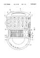
- FIG. 1 is a partial elevation of an emergency information apparatus in accordance with the present invention
- FIGS. 2A and 2B are electronic block diagrams of the apparatus of FIG. 1;
- FIGS. 3 and 4 are flow chart(s) of the operations of the apparatus of FIG. 1;
- FIG. 5 is a back side view of the apparatus of FIG. 1.
- the external portion of the apparatus is comprised primarily of a casing 100.
- the casing 100 is preferably of a rigid material, such as hard plastic, PVC, or the like.
- the casing and the items disposed in and within the casing 100 are, together, water resistant, such that water will not seep into the internal portion of the apparatus and induce electrical shorts or corrosion. This is beneficial so that the apparatus may be used, for example, in the rain, or during fire emergencies when water is being used to dowse the fire.
- the bottom of the casing 100 (not shown) preferably includes shock absorbing pads, such as rubber pads embedded within the casing 100 and exposed at the outer edge of the casing 100 to reduce shock and vibration when the apparatus is set down.
- a hinged compartment 180 On the left side of the apparatus there is a hinged compartment 180.
- the compartment 180 is in a closed and locked position, as shown.
- the compartment 180 may be opened through a release (not shown), which may be on the side or top of the apparatus as known in the art.
- the compartment 180 is adapted for receiving a program medium, preferably a compact disc (CD) (not shown). When open, the compartment 180 may received a CD, and when closed, the compartment 180 holds the CD within the apparatus.
- a program medium preferably a compact disc (CD) (not shown).
- CD compact disc
- CDs are relatively inexpensive to produce and manufacture.
- CDs are resistant to corrosion and environmental influences.
- the typical user is comfortable with the use of CDs, for example their insertion into a player and operation of a CD player.
- playback of a CD may be quickly moved from one area to another, permitting rapid movement between programs and instructions.
- a standard audio CD stores information in stereo, thereby permitting rapid switching between languages on a bilingual CD, as explained below.
- Sixth, updated CDs can be exchanged for old CDs having outdated information.
- the CD is preferably within accepted standards as to form.
- the CD may be manufactured using well known methods.
- the CD stores emergency information in a plurality of programs, and each program is made up of one or more instructions.
- a program may include the audio portion of the emergency information to be presented to a user. This aspect is like that of typical CDs.
- the programs may also include dual tone multifrequency (DTMF) data. This DTMF data provides control signals to the emergency information apparatus, and may be used, for example, so that a particular program, upon its end, causes an indicated next program to be played.
- DTMF dual tone multifrequency
- the program selectors 110 are used for selecting and thereby starting the playback of programs stored on a CD which has been properly inserted into the compartment 180.
- the number of program selectors 110 is not critical, although several should be provided so that several emergencies may be addressed by any one CD.
- playback selectors 160 including a pause key 160H, a reverse key 160R, a forward key 160F and a continue play key 160P.
- the program selectors 110 and the playback selectors 160 are preferably push buttons.
- a light sensor (not shown).
- the light sensor is of the typical variety.
- the program selectors 110 and playback selectors 160 preferably are backlit, and the lights for the selectors 110, 160 are preferably coupled to the light sensor, such that the selectors 110, 160 are automatically illuminated when the ambient light falls below a selected threshold.
- the design and construction of such circuits are well within the ability of those of ordinary skill in the art, so further description is not provided.
- a nearly limitless number of programs may be used with the apparatus. Simply by changing CDs, a new set of programs may be made available. To accommodate this flexibility, the program selectors 110 are preferably labelled with numbers 1-15, and these numbers correspond to programs on a CD (which is adapted for use with the apparatus).
- Programs may include instructions relating to AIDS/HIV, bloody nose, bumps and bruises, burns, choking, CPR, dental injuries, drowning, earthquakes, electric shock, external bleeding, eye injuries, fires, fractures and dislocations, frostbite and hypothermia, heart attack, heat emergencies, inset stings and bites, internal injuries, muscle cramps, poisoning; rescue breathing, seizures and shock, stroke, spinal injuries, sprains and strains, and emergency action principles.
- each CD there is preferably provided a removable overlay 115.
- the overlay 115 is adapted to be placed over and around the program selectors 110.
- the overlay 115 labels the program selectors 110 in accordance with the programs stored on the CD. Thus, by scanning the overlay 115, the user can determine which program selector 110 to press to begin playback of a desired program.
- the overlay 115 is preferably a thin piece of plastic, with the labels being resistant to erasure from typical use of the apparatus.
- the program selectors 110 are stenciled with the appropriate program name.
- Aftermarket CDs may be provided with appropriately labelled for covering over the stencils.
- the apparatus further includes a speaker 120 for playing back the audio portion of the programs stored on the CD.
- the speaker 120 is preferably disposed behind a grill 121.
- the grill 121 prevents damage to the speaker 120 from rigid objects which could puncture and thereby damage the speaker, and preferably prevent water from reaching the speaker 120.
- Disposed in the casing 100 and preferably near the speaker 120 is a volume control 125.
- the volume control 125 may be operated by the user to adjust the volume of the program playback from the speaker 120.
- the speaker's volume may not be reduced below a predetermined threshold. This prevents the volume control 125 from being set so low that the user is not aware that a program is playing.
- the speaker 120 is shown in FIG. 1 as disposed substantially above the compartment 180. However, if the speaker is deep, then it would be preferable to swap the positions of the speaker 120 and the playback selectors 160 with the positions of the program selectors 110.
- the display 170 is preferably a backlit liquid crystal display, although any device which is compact and can display the program number is suitable. This may include a series of LEDs or even a mechanical means.
- the apparatus is further provided with a handle 190.
- the handle 190 is adapted for easy holding by the user. Because most people are right handed, the handle is disposed on the right side of the apparatus. Furthermore, the weight of the apparatus is preferably balanced to ease any potential strain on the-holder of the handle 190.
- indicator lamps 155, 156 are disposed within the casing 100.
- One indicator lamp 155 is provided to indicate when the apparatus is powered-on.
- the other lamp 156 is provided to indicate when the battery is low.
- These lamps are preferably red and amber LEDs, respectively, although other colors and other types of indicators may be suitable.
- the CD may include programs having a multilingual audio portion.
- a language selector 185 in the casing.
- the language selector 185 is preferably a two-position (A and B) switch having labels which turn with the switch. More preferably, the language selector 185 allows selection of any of four languages. This labelling is preferably on the overlay 115. To select a language to be played, the language selector 185 is set to one of its two positions. Thus, emergency information may be provided by the apparatus in a multiplicity of languages, simply by moving the language selector 185, or changing CDs (and the accompanying overlay 115).
- a flashlight is also preferably included within the apparatus.
- FIG. 5 there is shown a side view of the apparatus.
- the handle 190 is on the left and the compartment 180 is on the right.
- the flashlight 550 Centrally located on the side of the casing 100 and towards the left on FIG. 5 is a flashlight 550.
- the flashlight 550 includes a bulb 555 which is aimed away from the casing 100 at about a 90° angle from the longitudinal axis of the handle 190.
- the flashlight 550 has an independent power supply, with a power switch 570 disposed in the casing 100 on the handle 190.
- the flashlight 550 is preferably arranged such that when the batteries wear out, the front facing of the flashlight 560 is removed and the batteries (not shown) are replaced.
- the flashlight 550 comprises an ordinary disposable flashlight which slides into the casing 100. Accordingly, when the flashlight's batteries wear out, the flashlight 550 is replaced.
- the flashlight 550 is further integrated with the apparatus.
- the flashlight draws power from the power subsystem 204. This ensures that the flashlight has sufficient power.
- the flashlight could also be coupled to the light sensor, such that the light level is adjusted automatically.
- the flashlight 550 is preferably located as shown to permit the user to manipulate the selectors 110, 160 while aiming the flashlight away from himself. Since the apparatus may be used while the user is walking, the provision of the flashlight is seen to be quite beneficial in low light environments.
- FIGS. 2A and 2B there are shown electronic block diagrams of the apparatus of FIG. 1.
- the electronics of the apparatus may be separated into five logical subsystems: a playback subsystem 201, a control subsystem 202, an input subsystem 205, an output subsystem 203 and a power subsystem 204.
- the playback subsystem 201 preferably comprises a CD player 280.
- the playback subsystem 201 is at least partially disposed within the compartment 180.
- the compartment 180 opens into the CD player 280, and forms the cover for the CD player 280.
- the CD player 280 may be a standard compact, portable CD playback device, such as the Philips CD 4000.
- the input subsystem comprises a 3 ⁇ 5 keyboard 210, a 4 ⁇ 1 switch bank 265, a latch 260, and a channel selector 285.
- the program selectors 110 are coupled to the 3 ⁇ 5 keyboard 210.
- the playback selectors 160 are coupled to the switch bank 265, and the switch bank 265 is coupled to the latch 260. When a playback selector 160 is pressed while the power is on, the identity of the pressed selector 160 is latched by the latch 260.
- the CD player 280 provides output on channel lines 280A and 280B.
- the channel lines 280A, 280B would carry respectively the left and right channel of a stereo recording.
- separate programs e.g., the same program in two languages
- the channel selector 285 receives the outputs from the CD player and under the control of the language selector 185, selects one of the two signals 280A, 280B and outputs that signal on the channel select output 2850.
- the control subsystem 202 comprises a microcontroller 290, a 2 of 8 decoder 215, and a DTMF decoder 295.
- the microcontroller 290 is preferably an Intel 8084 8-bit 3-port microprocessor having on-chip memory (ROM and RAM), and at least one I/O port. One port of the microcontroller 290 is coupled to the CD player 280.
- the data bus of the microcontroller 290 is coupled to the two of eight decoder 215, the latch 260, and the DTMF decoder 295.
- the microcontroller 290 preferably includes a program for operating the apparatus in ROM. Although a particular microcontroller is disclosed, no microcontroller is considered better than any other for use in the apparatus. Because programs will be different for different microcontrollers, a complete program is not disclosed. However, one of ordinary skill in the art having knowledge of microcontroller programming could use this disclosure, including the description of the operation of the apparatus below and the drawings, to produce an appropriate program in a short period of time.
- the 2 of 8 decoder 215 decodes the output of the keyboard 210.
- the microcontroller 290 determines which key on the keyboard 210 is being pressed using conventional techniques, such as periodic scanning.
- the microcontroller 290 detects the activation of a playback selector 160 by scanning the latch 260.
- the microcontroller 290 also scans the DTMF decoder 295.
- Each of the latch 260, the 2 of 8 decoder 215 and the DTMF decoder 295 are enabled by the microcontroller 290 by an enable line, labeled as "E" for each of these devices on FIG. 2A.
- the DTMF decoder 295 may be of conventional design, such as a Motorola MC145436P.
- the DTMF decoder 295 converts tones received from the channel selector 285 to digital (i.e., binary) data, which the microcontroller 290 can process.
- the DTMF data stored on a CD is preferably encoded.
- a particular coding scheme is not preferred.
- the coding scheme preferably provides a set data format. For example, the first several bits might represent a command, such as "jump to another track on the CD," and the next several bits might represent data for the command, such as an address for the jump.
- Such a coding scheme could be employed to provide any number and type of control commands.
- a number of commands are provided.
- One preferred command causes playback to move to another location on the disk. Such location is preferably included in the DTMF data. Another causes playback to end. Yet another alters playback volume. Another powerful command pauses playback until an input is received.
- condition command would be useful for providing CPR instructions, since a rescuer administering CPR should be doing steps at particular times, and different steps should be taken depending on the condition of the victim.
- one program selector 110 could be generally labelled “CPR” and when pressed, the program would ask a question, such as "Is the victim a child? If yes, press the ⁇ yes ⁇ key.” By providing a program selector labelled “Yes,” the apparatus can be used to determine whether the victim is a child, and then play the appropriate program.
- DTMF data may be stored at the beginning of the CD to represent index information of the programs and instructions on the CD. Also, if the apparatus is provided with an appropriate display as shown in FIG. 1, the DTMF data could include text for display during program playback.
- the microcontroller 290 is coupled to the CD player 280 for program and instruction selection as well as control of stopping and pausing of programs.
- the CD may include the programs for plural languages in the same channel. These programs are preferably placed on the CD, either at predefined positions, or else at positions included in the index information. For example, for a CD capable of holding up to 72 minutes of audio programs, the CD can store four programs of 36 minutes each. Manipulation of the language selector results in either the control subsystem moving to another track or the channel selector 285 switching channels, or both.
- the output subsystem comprises an amplifier 225 coupled to a speaker 220.
- the amplifier receives the output from the channel selector 285.
- the amplifier may be, for example, a five watt audio amplifier, and the speaker 220 may be a conventional, low weight speaker.
- the volume control 125 is used to adjust the volume of the speaker. Although not shown, those of ordinary skill will recognize that the volume control 125 may be coupled to the amplifier in the conventional manner.
- the volume control 125 may be coupled to the microcontroller 290, for example via an I/O port of the microcontroller 290.
- the microcontroller would also be coupled to the amplifier 225.
- the microcontroller would be programmed to scan the setting of the volume control 125, and, based upon the setting of the volume control 125, would control the amplifier 's output.
- the power subsystem comprises a battery pack 250, a battery charger 230, a diode D1, a capacitor C1, a voltage regulator 240 and a lamp 255.
- the battery pack 250 is preferably a NiCAD type cell.
- the battery charger 230 may be of the conventional type with a connector for external power in the form of an ordinary household two-prong jack (not shown). Preferably, this jack can be flipped out from the surface of the casing 100 at the back of the apparatus and plugged directly into an ordinary electrical outlet.
- the batter charger 230 is coupled to the battery pack 250. Thus, when the apparatus is plugged into an outlet, the batter charger 230 charges the battery pack 250 and supports the apparatus.
- a lamp 255 is also coupled to the battery pack 250 via a switch SW20. This lamp 255, is coupled to the indicator 155 in the casing to indicate when the apparatus is fully active.
- the voltage regulator 240 provides power conditioning to prevent the sensitive circuitry of the various electronic components from being damaged. As shown in 25 FIG. 2A, the voltage regulator 240 is coupled to the battery pack 250, the battery charger 230, the external power supply, and to the 2 of 8 decoder 215.
- the keyboard 210 always receives power from the voltage regulator. Thus, even when the apparatus is in a power-off state, pressing a program selector 110 activates a switch in the keyboard 210 which is decoded by the 2 of 8 decoder 215.
- the 2 of 8 decoder 210 preferably includes electronic switches (not shown), which control power to the other components of the apparatus.
- the electronic switches are open-when the apparatus is in a power-off state.
- the electronic switches are controlled by the 2 of 8 decoder 215 in a way that when the decoder 215 detects a signal from the keyboard 210, the electronic switches close.
- the apparatus enters a power-on state without the user having to utilize a separate power switch.
- FIG. 3 there is shown a flowchart for the operation of the apparatus from the power-off state.
- the process begins at step 305 with activation of the keyboard 210 upon the depression of one of the program selectors 110.
- the 2 of 8 decoder 215 detects the pressing of a program selector 110 as described above, and allows power to flow to the other components of the apparatus.
- two separate processes begin and run simultaneously.
- the apparatus determines which language has been selected (Step 315). If the language selector 185 is in the A position, then the program in the CD's channel A will be provided as the output of the channel selector 285. Alternatively, if the language selector 185 is in the B position, then the output of the channel selector 285 will be from the B channel of the CD (Step 325).
- provision of the language selector 185 permits very rapid changing between two languages. This is because the program in the first language is played at the same time as the program in the second language, and switching between the programs is substantially instantaneous upon the change of the position of language selector 185.
- the keyboard 210 is decoded (Step 340) by the 2 of 8 decoder 215.
- the microprocessor accepts the decoded keyboard information representing the identity of the selected program selector 110 (Step 340).
- the microcontroller uses the identification of the selected program selector 110 to enable playback of the selected program from the CD player.
- the CD contains DTMF encoded index information located at a predetermined position which is played back upon power-up.
- the microcontroller Upon power up, the microcontroller causes the CD player to begin playback of the DTMF encoded index information.
- the index information is received by the microcontroller 290 via the DTMF decoder 295.
- the microcontroller 290 identifies the desired program to play and commands the CD player 280 to play the program based upon the index information.
- the programs of every CD may be placed at fixed positions on the CDs. In this way, for all CDs, the programs are stored at consistent relative positions. For example, program 3 on every CD would be in the same place.
- the CD player 280 will then play the prerecorded program on the CD (Step 350). Also, the power-on lamp 255 is activated (Step 355).
- the DTMF encoded index information also includes the positions of each instruction within each program.
- the various playback selectors 160 may be manipulated to pause the play, reverse by one instruction, advance by one instruction, or resume play.
- each instruction is made as short as possible, to permit easy movement by the user through the program using the reverse selector 160R and forward selector 160F. If the location of the instructions is not known, as would be the case in simpler embodiments, then the reverse selector 160R and forward selector 160F would move playback by a set amount, such as one track.
- Step 405 When playback of a program on the CD ends (Step 405), normally the apparatus will return to its power-off state (Step 415) and the power indicator 255 is turned off. However, if DTMF data is in the program at the end of the program (Step 410) then the DTMF data is decoded by the DTMF decoder 265 (Step 420).
- the DTMF data may identify another program on the CD for playback.
- the microcontroller 290 determines which program is indicated by the DTMF data (Step 470) and activates the playback of the indicated program in the CD player 280 (Step 475). Playback of the indicated program may then continue as if it was a selected program, and the user may move through the program using the playback selectors 160 and switch languages using the language selector 185.
- the invention includes other aspects which provide further benefits.
- Another preferable aspect of the apparatus is a storage space for a second CD and overlay.
- the second compartment is also preferably easily accessibly by the ordinary user.
- the second CD could store programs for additional emergencies or languages.
- the apparatus and methods of the present invention are well suited for use in factories, schools, homes, etc. for training and for providing non-emergency information.
- information on how to use machinery in a factory, or recipes for preparing food, can be carried and placed as desired.
- the device could be used to provide information to museum and park visitors, with the program selectors corresponding to particular attractions and sites.
Abstract
Description
Claims (14)
Priority Applications (2)
| Application Number | Priority Date | Filing Date | Title |
|---|---|---|---|
| US08/239,242 US5521812A (en) | 1994-05-06 | 1994-05-06 | Emergency information apparatus and method |
| US08/555,883 US5668954A (en) | 1994-05-06 | 1995-11-14 | Instructional CD player |
Applications Claiming Priority (1)
| Application Number | Priority Date | Filing Date | Title |
|---|---|---|---|
| US08/239,242 US5521812A (en) | 1994-05-06 | 1994-05-06 | Emergency information apparatus and method |
Related Child Applications (1)
| Application Number | Title | Priority Date | Filing Date |
|---|---|---|---|
| US08/555,883 Division US5668954A (en) | 1994-05-06 | 1995-11-14 | Instructional CD player |
Publications (1)
| Publication Number | Publication Date |
|---|---|
| US5521812A true US5521812A (en) | 1996-05-28 |
Family
ID=22901261
Family Applications (2)
| Application Number | Title | Priority Date | Filing Date |
|---|---|---|---|
| US08/239,242 Expired - Lifetime US5521812A (en) | 1994-05-06 | 1994-05-06 | Emergency information apparatus and method |
| US08/555,883 Expired - Lifetime US5668954A (en) | 1994-05-06 | 1995-11-14 | Instructional CD player |
Family Applications After (1)
| Application Number | Title | Priority Date | Filing Date |
|---|---|---|---|
| US08/555,883 Expired - Lifetime US5668954A (en) | 1994-05-06 | 1995-11-14 | Instructional CD player |
Country Status (1)
| Country | Link |
|---|---|
| US (2) | US5521812A (en) |
Cited By (50)
| Publication number | Priority date | Publication date | Assignee | Title |
|---|---|---|---|---|
| US5781515A (en) * | 1994-12-20 | 1998-07-14 | Sanyo Electric Co., Ltd. | Disk information reproduction apparatus and method using avoid band control signals |
| US5850630A (en) * | 1994-06-13 | 1998-12-15 | Wilson; J. Anthony | Tool kit with audible prompting for first aid and the like |
| US5857966A (en) * | 1996-03-29 | 1999-01-12 | Clawson; Jeffrey J. | Method and system for the unconscious or fainting protocol of an emergency medical dispatch system |
| US5983284A (en) * | 1997-01-10 | 1999-11-09 | Lucent Technologies Inc. | Two-button protocol for generating function and instruction messages for operating multi-function devices |
| US6010451A (en) * | 1996-03-29 | 2000-01-04 | Clawson; Jeffrey J. | Method and system for giving remote emergency medical counsel to choking patients |
| US6053864A (en) * | 1996-03-29 | 2000-04-25 | Clawson; Jeffrey J. | Method and system for giving remote emergency medical counsel to arrest patients |
| US6106459A (en) * | 1996-03-29 | 2000-08-22 | Clawson; Jeffrey J. | Method and system for the entry protocol of an emergency medical dispatch system |
| US6201772B1 (en) | 1994-12-20 | 2001-03-13 | Sanyo Electric Co., Ltd. | Cards used for disk reproduction apparatus |
| US6607481B1 (en) | 2000-10-10 | 2003-08-19 | Jeffrey J. Clawson | Method and system for an improved entry process of an emergency medical dispatch system |
| US20030208357A1 (en) * | 2002-05-06 | 2003-11-06 | Dlh, Inc. | First aid kit instructions |
| US20030212575A1 (en) * | 2002-05-07 | 2003-11-13 | Richard Saalsaa | Method and system for a seamless interface between an emergency medical dispatch system and a nurse triage system |
| US20040064342A1 (en) * | 2002-09-30 | 2004-04-01 | Browne David W. | Health care protocols |
| US6758811B1 (en) | 2000-03-10 | 2004-07-06 | Safetymate, Inc. | Internet server apparatus, method and device for implementing emergency information instructions |
| US6771172B1 (en) * | 1999-11-11 | 2004-08-03 | General Electric Company | Portable patient monitor with alarm light integrated into handle |
| US20040214148A1 (en) * | 2003-04-22 | 2004-10-28 | Salvino Robert J. | Updating health care protocols |
| US20040249419A1 (en) * | 2003-04-02 | 2004-12-09 | Chapman Fred William | Defibrillators customized for anticipated patients |
| US20050015115A1 (en) * | 2003-07-16 | 2005-01-20 | Sullivan Joseph L. | First aid system |
| US20050027173A1 (en) * | 2003-07-31 | 2005-02-03 | Briscoe Kathleen E. | Brain injury protocols |
| US20060137699A1 (en) * | 2004-12-23 | 2006-06-29 | Moore Mark P | Providing data destination information to a medical device |
| US20070055559A1 (en) * | 2001-09-25 | 2007-03-08 | Clawson Jeffrey J | Method and system for the fire response dispatch protocol of an emergency dispatch system |
| US20070116189A1 (en) * | 2001-09-26 | 2007-05-24 | Clawson Jeffrey J | Method and system for the police response dispatch protocol of an emergency dispatch system |
| US7259667B2 (en) | 2005-02-22 | 2007-08-21 | Lolita C. Sergio | Compact portable emergency aid apparatus |
| US7324803B2 (en) | 2005-07-07 | 2008-01-29 | Christine Moyes | Emergency settings for cellular telephones |
| WO2008024098A2 (en) * | 2006-08-18 | 2008-02-28 | Sergio Lolita C | Compact portable emergency aid apparatus |
| US7428301B1 (en) * | 2000-10-09 | 2008-09-23 | Clawson Jeffrey J | Method and system for the exit protocol of an emergency medical dispatch system |
| US20080310600A1 (en) * | 2007-06-13 | 2008-12-18 | Clawson Jeffrey J | Diagnostic and intervention tools for emergency medical dispatch |
| EP2077494A2 (en) | 2004-07-02 | 2009-07-08 | Safetymate, Inc | Internet server apparatus, method and device for implementing emergency information instructions |
| US20110064204A1 (en) * | 2009-09-11 | 2011-03-17 | Clawson Jeffrey J | Stroke diagnostic and intervention tool for emergency dispatch |
| US20110066002A1 (en) * | 2009-09-14 | 2011-03-17 | Clawson Jeffrey J | Pandemic diagnostic and intervention tool for emergency dispatch |
| US20110205052A1 (en) * | 2010-02-24 | 2011-08-25 | Clawson Jeffrey J | Burn diagnostic and intervention tool for emergency dispatch |
| US8066638B2 (en) | 2007-06-13 | 2011-11-29 | Clawson Jeffrey J | Diagnostic and intervention tools for emergency medical dispatch |
| US8396191B2 (en) | 2011-02-11 | 2013-03-12 | Jeffrey J. Clawson | Anti-social protocol for emergency dispatch |
| US8488748B2 (en) | 2011-01-19 | 2013-07-16 | Jeffrey J. Clawson | Meningitis diagnostic and intervention tool for emergency dispatch |
| US8582866B2 (en) | 2011-02-10 | 2013-11-12 | Edge 3 Technologies, Inc. | Method and apparatus for disparity computation in stereo images |
| US8647123B1 (en) | 2005-06-15 | 2014-02-11 | Retrac, Inc. | First responder emergency situation assistance device |
| US8670526B2 (en) | 2011-02-11 | 2014-03-11 | Jeffrey J. Clawson | Hate crime diagnostic and intervention tool for emergency dispatch |
| US8712020B2 (en) | 2012-09-06 | 2014-04-29 | Jeffrey J. Clawson | Pandemic protocol for emergency dispatch |
| US8873719B2 (en) | 2013-01-31 | 2014-10-28 | Jeffrey J. Clawson | Active assailant protocol for emergency dispatch |
| US8971501B2 (en) | 2009-04-13 | 2015-03-03 | Priority Dispatch Corporation | Methods and systems to identify code hierarchy bias in medical priority dispatch systems |
| US9286440B1 (en) | 2005-06-15 | 2016-03-15 | Retrac, Inc. | Self-contained emergency situation assistance kit with programmed audio and visual instructions |
| US9319859B2 (en) | 2013-01-31 | 2016-04-19 | Jeffrey J. Clawson | System and method for text messaging for emergency response |
| US9516166B1 (en) | 2015-05-28 | 2016-12-06 | Jeffrey J. Clawson | Chemical suicide protocol for emergency response |
| US9877171B2 (en) | 2016-04-08 | 2018-01-23 | Jeffrey J. Clawson | Picture/video messaging protocol for emergency response |
| US10639122B2 (en) | 2011-09-08 | 2020-05-05 | Zoll Medical Corporation | Medical tool kit |
| US10657614B2 (en) | 2015-12-23 | 2020-05-19 | Jeffrey J. Clawson | Locator diagnostic system for emergency dispatch |
| US10699548B2 (en) | 2018-04-19 | 2020-06-30 | Jeffrey J. Clawson | Expedited dispatch protocol system and method |
| US11547616B2 (en) | 2016-04-27 | 2023-01-10 | Zoll Medical Corporation | Portable medical triage kit |
| US11910471B2 (en) | 2021-04-23 | 2024-02-20 | Priority Dispatch Corp. | System and method for emergency dispatch |
| US11937160B2 (en) | 2021-04-23 | 2024-03-19 | Priority Dispatch Corporation | System and method for emergency dispatch |
| US11957492B2 (en) | 2021-03-31 | 2024-04-16 | Zoll Medical Corporation | Medical tool kit |
Families Citing this family (7)
| Publication number | Priority date | Publication date | Assignee | Title |
|---|---|---|---|---|
| US6594634B1 (en) * | 1998-09-14 | 2003-07-15 | Medtronic Physio-Control Corp. | Method and apparatus for reporting emergency incidents |
| FR2788355A1 (en) * | 1999-01-12 | 2000-07-13 | Team Concepts Europ | ELECTRONIC EDUCATIONAL GAME |
| US7987510B2 (en) * | 2001-03-28 | 2011-07-26 | Rovi Solutions Corporation | Self-protecting digital content |
| GB2396115A (en) * | 2002-12-14 | 2004-06-16 | Adrienne Jay Over | Resuscitation prompting device |
| US8055910B2 (en) | 2003-07-07 | 2011-11-08 | Rovi Solutions Corporation | Reprogrammable security for controlling piracy and enabling interactive content |
| US20060155545A1 (en) * | 2005-01-11 | 2006-07-13 | Hosanna, Inc. | Multi-source powered audio playback system |
| DE202006008932U1 (en) * | 2006-06-07 | 2006-08-24 | Arndt, Mike | Speech module for security/first aid chests has circuit board, parts to play back speech after activation by touch, signal, sound or blue tooth and energy source |
Citations (10)
| Publication number | Priority date | Publication date | Assignee | Title |
|---|---|---|---|---|
| US3845250A (en) * | 1972-02-22 | 1974-10-29 | Brien G O | Manual key operated message generator |
| US4303395A (en) * | 1979-06-11 | 1981-12-01 | Bower James C | Emergency audible instruction apparatus for a fire extinguisher |
| US4583524A (en) * | 1984-11-21 | 1986-04-22 | Hutchins Donald C | Cardiopulmonary resuscitation prompting |
| US4588383A (en) * | 1984-04-30 | 1986-05-13 | The New Directions Group, Inc. | Interactive synthetic speech CPR trainer/prompter and method of use |
| US5025374A (en) * | 1987-12-09 | 1991-06-18 | Arch Development Corp. | Portable system for choosing pre-operative patient test |
| US5059126A (en) * | 1990-05-09 | 1991-10-22 | Kimball Dan V | Sound association and learning system |
| US5086391A (en) * | 1989-02-24 | 1992-02-04 | Chambers Bryan R | Remote controller for activating speech messages and for contacting emergency services |
| US5088037A (en) * | 1990-03-23 | 1992-02-11 | Anthony Battaglia | Portable rescue administration aid device |
| US5185857A (en) * | 1989-12-13 | 1993-02-09 | Rozmanith A Martin | Method and apparatus for multi-optional processing, storing, transmitting and retrieving graphical and tabular data in a mobile transportation distributable and/or networkable communications and/or data processing system |
| US5274560A (en) * | 1990-12-03 | 1993-12-28 | Audio Navigation Systems, Inc. | Sensor free vehicle navigation system utilizing a voice input/output interface for routing a driver from his source point to his destination point |
Family Cites Families (3)
| Publication number | Priority date | Publication date | Assignee | Title |
|---|---|---|---|---|
| US4569026A (en) * | 1979-02-05 | 1986-02-04 | Best Robert M | TV Movies that talk back |
| US4677552A (en) * | 1984-10-05 | 1987-06-30 | Sibley Jr H C | International commodity trade exchange |
| US5106097A (en) * | 1988-07-12 | 1992-04-21 | Rykodisc | Audio quiz game |
-
1994
- 1994-05-06 US US08/239,242 patent/US5521812A/en not_active Expired - Lifetime
-
1995
- 1995-11-14 US US08/555,883 patent/US5668954A/en not_active Expired - Lifetime
Patent Citations (10)
| Publication number | Priority date | Publication date | Assignee | Title |
|---|---|---|---|---|
| US3845250A (en) * | 1972-02-22 | 1974-10-29 | Brien G O | Manual key operated message generator |
| US4303395A (en) * | 1979-06-11 | 1981-12-01 | Bower James C | Emergency audible instruction apparatus for a fire extinguisher |
| US4588383A (en) * | 1984-04-30 | 1986-05-13 | The New Directions Group, Inc. | Interactive synthetic speech CPR trainer/prompter and method of use |
| US4583524A (en) * | 1984-11-21 | 1986-04-22 | Hutchins Donald C | Cardiopulmonary resuscitation prompting |
| US5025374A (en) * | 1987-12-09 | 1991-06-18 | Arch Development Corp. | Portable system for choosing pre-operative patient test |
| US5086391A (en) * | 1989-02-24 | 1992-02-04 | Chambers Bryan R | Remote controller for activating speech messages and for contacting emergency services |
| US5185857A (en) * | 1989-12-13 | 1993-02-09 | Rozmanith A Martin | Method and apparatus for multi-optional processing, storing, transmitting and retrieving graphical and tabular data in a mobile transportation distributable and/or networkable communications and/or data processing system |
| US5088037A (en) * | 1990-03-23 | 1992-02-11 | Anthony Battaglia | Portable rescue administration aid device |
| US5059126A (en) * | 1990-05-09 | 1991-10-22 | Kimball Dan V | Sound association and learning system |
| US5274560A (en) * | 1990-12-03 | 1993-12-28 | Audio Navigation Systems, Inc. | Sensor free vehicle navigation system utilizing a voice input/output interface for routing a driver from his source point to his destination point |
Cited By (73)
| Publication number | Priority date | Publication date | Assignee | Title |
|---|---|---|---|---|
| US5850630A (en) * | 1994-06-13 | 1998-12-15 | Wilson; J. Anthony | Tool kit with audible prompting for first aid and the like |
| US6201772B1 (en) | 1994-12-20 | 2001-03-13 | Sanyo Electric Co., Ltd. | Cards used for disk reproduction apparatus |
| US5781515A (en) * | 1994-12-20 | 1998-07-14 | Sanyo Electric Co., Ltd. | Disk information reproduction apparatus and method using avoid band control signals |
| US5857966A (en) * | 1996-03-29 | 1999-01-12 | Clawson; Jeffrey J. | Method and system for the unconscious or fainting protocol of an emergency medical dispatch system |
| US6010451A (en) * | 1996-03-29 | 2000-01-04 | Clawson; Jeffrey J. | Method and system for giving remote emergency medical counsel to choking patients |
| US6053864A (en) * | 1996-03-29 | 2000-04-25 | Clawson; Jeffrey J. | Method and system for giving remote emergency medical counsel to arrest patients |
| US6106459A (en) * | 1996-03-29 | 2000-08-22 | Clawson; Jeffrey J. | Method and system for the entry protocol of an emergency medical dispatch system |
| US5983284A (en) * | 1997-01-10 | 1999-11-09 | Lucent Technologies Inc. | Two-button protocol for generating function and instruction messages for operating multi-function devices |
| US6771172B1 (en) * | 1999-11-11 | 2004-08-03 | General Electric Company | Portable patient monitor with alarm light integrated into handle |
| US20090111083A1 (en) * | 2000-03-10 | 2009-04-30 | Fyi Interactive, Inc. | Internet server apparatus, method and device for implementing emergency information instructions |
| US6758811B1 (en) | 2000-03-10 | 2004-07-06 | Safetymate, Inc. | Internet server apparatus, method and device for implementing emergency information instructions |
| USRE41808E1 (en) | 2000-03-10 | 2010-10-05 | Safetymate, Inc. | Internet server apparatus, method and device for implementing emergency information instructions |
| US7428301B1 (en) * | 2000-10-09 | 2008-09-23 | Clawson Jeffrey J | Method and system for the exit protocol of an emergency medical dispatch system |
| US6607481B1 (en) | 2000-10-10 | 2003-08-19 | Jeffrey J. Clawson | Method and system for an improved entry process of an emergency medical dispatch system |
| US20070055559A1 (en) * | 2001-09-25 | 2007-03-08 | Clawson Jeffrey J | Method and system for the fire response dispatch protocol of an emergency dispatch system |
| US8417533B2 (en) | 2001-09-25 | 2013-04-09 | Jeffrey J. Clawson | Method and system for the fire response dispatch protocol of an emergency dispatch system |
| US7436937B2 (en) | 2001-09-26 | 2008-10-14 | Clawson Jeffrey J | Method and system for the police response dispatch protocol of an emergency dispatch system |
| US20070116189A1 (en) * | 2001-09-26 | 2007-05-24 | Clawson Jeffrey J | Method and system for the police response dispatch protocol of an emergency dispatch system |
| US20030208357A1 (en) * | 2002-05-06 | 2003-11-06 | Dlh, Inc. | First aid kit instructions |
| US20030212575A1 (en) * | 2002-05-07 | 2003-11-13 | Richard Saalsaa | Method and system for a seamless interface between an emergency medical dispatch system and a nurse triage system |
| US8494868B2 (en) | 2002-05-07 | 2013-07-23 | Priority Dispatch Corporation | Method and system for a seamless interface between an emergency medical dispatch system and a nurse triage system |
| US20040064342A1 (en) * | 2002-09-30 | 2004-04-01 | Browne David W. | Health care protocols |
| US8090440B2 (en) | 2003-04-02 | 2012-01-03 | Physio Control, Inc. | Defibrillators customized for anticipated patients |
| US8090439B2 (en) | 2003-04-02 | 2012-01-03 | Physio Control, Inc. | Defibrillators customized for anticipated patients |
| US8090441B2 (en) | 2003-04-02 | 2012-01-03 | Physio Control, Inc. | Defibrillators customized for anticipated patients |
| US20100318143A1 (en) * | 2003-04-02 | 2010-12-16 | Physio-Control, Inc. | Defibrillators customized for anticipated patients |
| US20040249419A1 (en) * | 2003-04-02 | 2004-12-09 | Chapman Fred William | Defibrillators customized for anticipated patients |
| US20100318144A1 (en) * | 2003-04-02 | 2010-12-16 | Physio-Control, Inc. | Defibrillators customized for anticipated patients |
| US20100318145A1 (en) * | 2003-04-02 | 2010-12-16 | Physio-Control, Inc. | Defibrillators customized for anticipated patients |
| US7805190B2 (en) | 2003-04-02 | 2010-09-28 | Physio-Control, Inc. | Defibrillators customized for anticipated patients |
| US20040214148A1 (en) * | 2003-04-22 | 2004-10-28 | Salvino Robert J. | Updating health care protocols |
| US20100297594A1 (en) * | 2003-07-16 | 2010-11-25 | Physio-Control, Inc. | Interactive first aid information system |
| US20050015115A1 (en) * | 2003-07-16 | 2005-01-20 | Sullivan Joseph L. | First aid system |
| US7623915B2 (en) | 2003-07-16 | 2009-11-24 | Medtronic Physio-Control Corp. | Interactive first aid information system |
| US20100087883A1 (en) * | 2003-07-16 | 2010-04-08 | Medtronic Physio-Control Corp. | Interactive first aid information system |
| US20050027173A1 (en) * | 2003-07-31 | 2005-02-03 | Briscoe Kathleen E. | Brain injury protocols |
| EP2077494A2 (en) | 2004-07-02 | 2009-07-08 | Safetymate, Inc | Internet server apparatus, method and device for implementing emergency information instructions |
| US20060137699A1 (en) * | 2004-12-23 | 2006-06-29 | Moore Mark P | Providing data destination information to a medical device |
| US7259667B2 (en) | 2005-02-22 | 2007-08-21 | Lolita C. Sergio | Compact portable emergency aid apparatus |
| US8647123B1 (en) | 2005-06-15 | 2014-02-11 | Retrac, Inc. | First responder emergency situation assistance device |
| US9286440B1 (en) | 2005-06-15 | 2016-03-15 | Retrac, Inc. | Self-contained emergency situation assistance kit with programmed audio and visual instructions |
| US7324803B2 (en) | 2005-07-07 | 2008-01-29 | Christine Moyes | Emergency settings for cellular telephones |
| WO2008024098A2 (en) * | 2006-08-18 | 2008-02-28 | Sergio Lolita C | Compact portable emergency aid apparatus |
| WO2008024098A3 (en) * | 2006-08-18 | 2008-09-18 | Lolita C Sergio | Compact portable emergency aid apparatus |
| US8103523B2 (en) | 2007-06-13 | 2012-01-24 | Clawson Jeffrey J | Diagnostic and intervention tools for emergency medical dispatch |
| US8066638B2 (en) | 2007-06-13 | 2011-11-29 | Clawson Jeffrey J | Diagnostic and intervention tools for emergency medical dispatch |
| US7645234B2 (en) | 2007-06-13 | 2010-01-12 | Clawson Jeffrey J | Diagnostic and intervention tools for emergency medical dispatch |
| US20080310600A1 (en) * | 2007-06-13 | 2008-12-18 | Clawson Jeffrey J | Diagnostic and intervention tools for emergency medical dispatch |
| US8971501B2 (en) | 2009-04-13 | 2015-03-03 | Priority Dispatch Corporation | Methods and systems to identify code hierarchy bias in medical priority dispatch systems |
| US8355483B2 (en) | 2009-09-11 | 2013-01-15 | Clawson Jeffrey J | Stroke diagnostic and intervention tool for emergency dispatch |
| US20110064204A1 (en) * | 2009-09-11 | 2011-03-17 | Clawson Jeffrey J | Stroke diagnostic and intervention tool for emergency dispatch |
| US8335298B2 (en) | 2009-09-14 | 2012-12-18 | Clawson Jeffrey J | Pandemic diagnostic and intervention tool for emergency dispatch |
| US20110066002A1 (en) * | 2009-09-14 | 2011-03-17 | Clawson Jeffrey J | Pandemic diagnostic and intervention tool for emergency dispatch |
| US8294570B2 (en) | 2010-02-24 | 2012-10-23 | Clawson Jeffrey J | Burn diagnostic and intervention tool for emergency dispatch |
| US20110205052A1 (en) * | 2010-02-24 | 2011-08-25 | Clawson Jeffrey J | Burn diagnostic and intervention tool for emergency dispatch |
| US8488748B2 (en) | 2011-01-19 | 2013-07-16 | Jeffrey J. Clawson | Meningitis diagnostic and intervention tool for emergency dispatch |
| US8582866B2 (en) | 2011-02-10 | 2013-11-12 | Edge 3 Technologies, Inc. | Method and apparatus for disparity computation in stereo images |
| US8670526B2 (en) | 2011-02-11 | 2014-03-11 | Jeffrey J. Clawson | Hate crime diagnostic and intervention tool for emergency dispatch |
| US8396191B2 (en) | 2011-02-11 | 2013-03-12 | Jeffrey J. Clawson | Anti-social protocol for emergency dispatch |
| US10639122B2 (en) | 2011-09-08 | 2020-05-05 | Zoll Medical Corporation | Medical tool kit |
| US11013571B2 (en) | 2011-09-08 | 2021-05-25 | Zoll Medical Corporation | Medical tool kit |
| US8712020B2 (en) | 2012-09-06 | 2014-04-29 | Jeffrey J. Clawson | Pandemic protocol for emergency dispatch |
| US9319859B2 (en) | 2013-01-31 | 2016-04-19 | Jeffrey J. Clawson | System and method for text messaging for emergency response |
| US9491605B2 (en) | 2013-01-31 | 2016-11-08 | Jeffrey J. Clawson | Text messaging for emergency response |
| US8873719B2 (en) | 2013-01-31 | 2014-10-28 | Jeffrey J. Clawson | Active assailant protocol for emergency dispatch |
| US9516166B1 (en) | 2015-05-28 | 2016-12-06 | Jeffrey J. Clawson | Chemical suicide protocol for emergency response |
| US10657614B2 (en) | 2015-12-23 | 2020-05-19 | Jeffrey J. Clawson | Locator diagnostic system for emergency dispatch |
| US9877171B2 (en) | 2016-04-08 | 2018-01-23 | Jeffrey J. Clawson | Picture/video messaging protocol for emergency response |
| US11547616B2 (en) | 2016-04-27 | 2023-01-10 | Zoll Medical Corporation | Portable medical triage kit |
| US10699548B2 (en) | 2018-04-19 | 2020-06-30 | Jeffrey J. Clawson | Expedited dispatch protocol system and method |
| US11957492B2 (en) | 2021-03-31 | 2024-04-16 | Zoll Medical Corporation | Medical tool kit |
| US11910471B2 (en) | 2021-04-23 | 2024-02-20 | Priority Dispatch Corp. | System and method for emergency dispatch |
| US11937160B2 (en) | 2021-04-23 | 2024-03-19 | Priority Dispatch Corporation | System and method for emergency dispatch |
Also Published As
| Publication number | Publication date |
|---|---|
| US5668954A (en) | 1997-09-16 |
Similar Documents
| Publication | Publication Date | Title |
|---|---|---|
| US5521812A (en) | Emergency information apparatus and method | |
| US5088037A (en) | Portable rescue administration aid device | |
| US10980690B2 (en) | Automated caregiving device with prompting based on caregiver progress | |
| USRE41808E1 (en) | Internet server apparatus, method and device for implementing emergency information instructions | |
| US7259667B2 (en) | Compact portable emergency aid apparatus | |
| USRE34800E (en) | Cardiopulmonary resuscitation prompting | |
| US8647123B1 (en) | First responder emergency situation assistance device | |
| US5795213A (en) | Reading toy | |
| US5850630A (en) | Tool kit with audible prompting for first aid and the like | |
| JP3189723U (en) | Medication management device | |
| JP2005535806A5 (en) | ||
| US9286440B1 (en) | Self-contained emergency situation assistance kit with programmed audio and visual instructions | |
| CN104080512B (en) | For the language label of automated external defibrillator | |
| EP2077494A2 (en) | Internet server apparatus, method and device for implementing emergency information instructions | |
| WO2008063200A1 (en) | Birding acoustic feedback learning aid | |
| JP2006012096A (en) | Internet server device, method and device for realizing information instruction in emergency | |
| RU2729545C1 (en) | Multi-level communicator with assistant call button | |
| JP2000069144A (en) | Portable memory backup device | |
| CA2012614A1 (en) | Rescue administration aid device | |
| JP2815884B2 (en) | Voice recognition device | |
| CA2253688C (en) | Reading toy | |
| FR2393356A1 (en) | Automatic selection of individual therapeutic treatment - involves miniature computer assessing answers to questions permitting response describing personalised treatment | |
| WO2006115409A1 (en) | Device for providing instructions in emergency situations | |
| US20050008204A1 (en) | Way to avoid the accident of surgical operation of doctor and it's observable appliance | |
| Poole et al. | An Electronic System for Recording Ongoing Behavior in Real Time |
Legal Events
| Date | Code | Title | Description |
|---|---|---|---|
| AS | Assignment |
Owner name: FEDER, DAVID L., KANSAS Free format text: ASSIGNMENT OF ASSIGNORS INTEREST;ASSIGNOR:GOFF, MILTON L.;REEL/FRAME:007003/0005 Effective date: 19940505 |
|
| STCF | Information on status: patent grant |
Free format text: PATENTED CASE |
|
| FPAY | Fee payment |
Year of fee payment: 4 |
|
| REMI | Maintenance fee reminder mailed | ||
| AS | Assignment |
Owner name: SAFETYMATE CORPORATION, CALIFORNIA Free format text: ASSIGNMENT OF ASSIGNORS INTEREST;ASSIGNOR:FEDER, DAVID L.;REEL/FRAME:015320/0948 Effective date: 20040506 |
|
| AS | Assignment |
Owner name: SAFETYMATE, INC., CALIFORNIA Free format text: CHANGE OF NAME;ASSIGNOR:FYI INTERACTIVE, INC.;REEL/FRAME:015355/0619 Effective date: 20020411 |
|
| REIN | Reinstatement after maintenance fee payment confirmed | ||
| FP | Lapsed due to failure to pay maintenance fee |
Effective date: 20040528 |
|
| FPAY | Fee payment |
Year of fee payment: 8 |
|
| FEPP | Fee payment procedure |
Free format text: PETITION RELATED TO MAINTENANCE FEES FILED (ORIGINAL EVENT CODE: PMFP); ENTITY STATUS OF PATENT OWNER: SMALL ENTITY |
|
| FEPP | Fee payment procedure |
Free format text: PETITION RELATED TO MAINTENANCE FEES GRANTED (ORIGINAL EVENT CODE: PMFG); ENTITY STATUS OF PATENT OWNER: SMALL ENTITY |
|
| SULP | Surcharge for late payment | ||
| PRDP | Patent reinstated due to the acceptance of a late maintenance fee |
Effective date: 20050926 |
|
| REMI | Maintenance fee reminder mailed | ||
| FPAY | Fee payment |
Year of fee payment: 12 |