US5481541A - Method of operation of remote data/control apparatus with controlled response timing - Google Patents
Method of operation of remote data/control apparatus with controlled response timing Download PDFInfo
- Publication number
- US5481541A US5481541A US07/929,321 US92932192A US5481541A US 5481541 A US5481541 A US 5481541A US 92932192 A US92932192 A US 92932192A US 5481541 A US5481541 A US 5481541A
- Authority
- US
- United States
- Prior art keywords
- unit
- channel
- time
- time delay
- free
- Prior art date
- Legal status (The legal status is an assumption and is not a legal conclusion. Google has not performed a legal analysis and makes no representation as to the accuracy of the status listed.)
- Expired - Lifetime
Links
Images
Classifications
-
- H—ELECTRICITY
- H04—ELECTRIC COMMUNICATION TECHNIQUE
- H04L—TRANSMISSION OF DIGITAL INFORMATION, e.g. TELEGRAPHIC COMMUNICATION
- H04L12/00—Data switching networks
- H04L12/28—Data switching networks characterised by path configuration, e.g. LAN [Local Area Networks] or WAN [Wide Area Networks]
- H04L12/40—Bus networks
- H04L12/403—Bus networks with centralised control, e.g. polling
Definitions
- This invention relates to communications apparatus, such as remote data/control apparatus.
- the invention relates to improvements in communication protocols and communication systems having several remote terminal units and one or more master control centres communicating by radio, serial ports, dedicated lines and/or telephone lines.
- Typical applications include, but are not limited to supervisory control and data acquisition (SCADA) for water and waste water systems, electric utility distribution systems, oil and gas pipelines, early warning siren systems, communication control systems, irrigation control systems and roadside emergency callbox systems.
- SCADA supervisory control and data acquisition
- UK Patent Application No. 2236606A describes a communications system for data acquisition and control in which a contention period is provided during which different remote units can contend for access to the central unit. Different remote units request polling during contention time-slots and are then polled by the central unit during a polling period. When traffic is light, the contention period is reduced so that the remote units can be polled more frequently. Nevertheless, polling does not begin until the contention period ends, irrespective of the number of units contending for polling. The aforesaid arrangement does not address the reverse situation in which a central unit calls for a response from a remote unit.
- communications apparatus comprising a first unit and a second unit arranged to exchange messages over a communication channel, wherein the first unit has means for requesting a response from the second unit and means for communicating to the second unit a value representing a time delay and the second unit has means for monitoring the channel, determining when the channel becomes free and transmitting its response to the first unit delayed by said time delay after the channel becomes free, whereby the first unit is able to control the timing of responses from a number of said units and avoid collision between responses from said units.
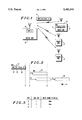
- FIG. 1 illustrates a remote data/control system in accordance with the prepared embodiment of the invention.
- FIG. 2 illustrates signals transmitted between the units of FIG. 1.
- FIG. 3 shows a table maintained in the central unit of FIG. 1.
- a central unit 10 and three remote units 11, 12 and 13.
- the remote units are typically data acquisition and control units which are connected to systems to be monitored or controlled, such as irrigation systems, alarm systems etc.
- the central unit 10 communications with the remote units 11, 12 and 13 in this example over a radio channel.
- the central unit 10 has means 14 for transmitting an outbound signalling word 15 (OSW).
- OSW is interpreted by a receiving unit as a request for a response.
- the means 14 can be considered to be a means for requesting a response from another unit.
- Each of the remote units 11, 12 and 13 is able to monitor the channel and determine when the channel is free--i.e. when neither the central unit 10 nor any other remote unit is communicating on the channel.
- the means for monitoring the channel comprise a received signal strength indicator in the demodulator on the receiver side of the unit, as is well known in the art (see, for example EP-B-0142503 or GB-A-2012525).
- the central unit 10 When the central unit 10 wishes to receive data from a remote unit 11, it "polls" that remote unit by transmitting the address of that remote unit and an instruction, which the remote unit interprets as a request for certain data.
- the data may be, for example, the status of an alarm, the flow rate through a valve etc.
- the remote unit 11 In response to an outbound signalling word (OSW) from the central unit 10 to a remote unit (e.g. unit 11), with an instruction requesting data, the remote unit 11 transmits an inbound signalling word (ISW) with the data requested.
- OSW outbound signalling word
- ISW inbound signalling word
- the central unit 10 transmits an OSW 20 comprising the address 21 of the remote unit 11, an instruction 22 and a value 23 representing a delay T1.
- the channel becomes free.
- the remote unit 11, and any other remote unit, e.g. unit 12, that wishes to transmit to the central unit 10 measures the signal strength on the channel, and determines that this has dropped below a threshold, and determines that the channel is free.
- FIG. 2 it is illustrated that the unit 11 is not necessarily immediately ready to make its response; in practice there may be a delay between the channel becoming free and the unit 11 being ready to respond. This delay extends to time A', but this is immaterial for present purposes).
- the unit waits a time T1 before transmitting its ISW. After delay T1, unit 11 transmits its ISW including the data requested. In the meantime, unit 12 has also noted that the channel became free at point A, and unit 12 has initiated a delay T2 before transmitting its ISW.
- the delay T2 may be initiated as a result of an earlier instruction from the central unit 10, or it may be a default delay. At the end of the delay T2, a channel is no longer available, because unit 11 is transmitting its ISW 25. Thus, the ISW 26 from unit 12 is not transmitted (indicated by dotted outline in FIG. 2), and instead unit 12 again waits for the channel to become free. When the channel becomes free at point B, unit 12 again waits an amount equal to the delay T2 and finally transmits its ISW 26 after that delay.
- unit 11 took precedence over unit 12 in transmitting its ISW, because the delay in unit 11 was shorter than the delay in unit 12.
- the priority allocated to unit 11 over unit 12 was allocated by central unit 10 by means of the delay information 23 contained in the OSW. In this way, unit 10 has control over the priority allocation between the remote units 11, 12 and 13 in a simple manner over a single channel.
- the delay information 23 can take the form of a number of discrete delay values. Each of these discrete delay values represents a time slot during which the remote unit will transmit its response.
- the central unit 10 stores a table correlating addresses of remote units with time slots. This table is shown in FIG. 3.
- remote unit (RTU) 11 has been allocated time slot 1 corresponding to a delay of 20 milliseconds and RTU 12 is allocated time slot 2 corresponding to a delay of 40 milliseconds. These delays represent the time each unit waits after any channel becomes free before transmitting.
- the central unit 10 When the central unit 10 receives an ISW from a remote unit, it releases the time slot previously allocated to that unit, for future allocation. Thus, in the table shown, RTU 13 has no time slot allocated to it, because the central unit 10 is not awaiting any response. Thus the central unit 10 can allocate any time slot from time slot 3 upwards to RTU 13.
- the remote unit When a remote unit wishes to report to the central unit without first being instructed by the central unit (e.g. to report an emergency), the remote unit allocates a time slot to itself, which may be a default time slot such as the first or last time slot or it may be a time slot plus offset (i.e. a time sub-slot) which may be unique to that unit or is pseudo-random.
- a time slot to itself, which may be a default time slot such as the first or last time slot or it may be a time slot plus offset (i.e. a time sub-slot) which may be unique to that unit or is pseudo-random.
- the time delay T1, T2 etc. and thus the position of the time slots is fixed, but is optimised according to the minimum sensitivity of the communication channel, i.e. how fast a remote unit recognises channel monitor (busy channel) after another remote unit has activated its push-to-torque.
- the response time to the first message attempt from the centre is independent of the remote unit addresses, and the desired function is achieved of remote units responding optimally without collisions.
- the number of assigned time-slots is limited per transmission burst, so that there will be no need to assign one time-slot for each remote unit, since this would considerably prolong the response time.
- a system with 100 remote units may utilise, say, only four time-slots. Once an remote unit has responded in its time-slot, this time-slot becomes free and can be used again by another remote unit in the next transmission.
Abstract
Description
Claims (4)
Applications Claiming Priority (2)
| Application Number | Priority Date | Filing Date | Title |
|---|---|---|---|
| GB9119186A GB2259387B (en) | 1991-09-07 | 1991-09-07 | Communications apparatus |
| GB9119186 | 1991-09-07 |
Publications (1)
| Publication Number | Publication Date |
|---|---|
| US5481541A true US5481541A (en) | 1996-01-02 |
Family
ID=10701095
Family Applications (1)
| Application Number | Title | Priority Date | Filing Date |
|---|---|---|---|
| US07/929,321 Expired - Lifetime US5481541A (en) | 1991-09-07 | 1992-08-13 | Method of operation of remote data/control apparatus with controlled response timing |
Country Status (7)
| Country | Link |
|---|---|
| US (1) | US5481541A (en) |
| AU (1) | AU654369B2 (en) |
| CA (1) | CA2075524C (en) |
| GB (1) | GB2259387B (en) |
| HK (1) | HK1000620A1 (en) |
| IL (1) | IL102715A (en) |
| NZ (1) | NZ244168A (en) |
Cited By (12)
| Publication number | Priority date | Publication date | Assignee | Title |
|---|---|---|---|---|
| US5638378A (en) * | 1994-12-22 | 1997-06-10 | Motorola, Inc. | Method of operating a communication system |
| US5648961A (en) * | 1994-11-21 | 1997-07-15 | Meisei Electric Co., Ltd. | Radio telephone system and antenna device and base station for the same |
| US5699353A (en) * | 1993-11-24 | 1997-12-16 | Ericsson Ge Mobile Communications, Inc. | Extended trunked RF communications systems networking |
| US5774459A (en) * | 1993-05-12 | 1998-06-30 | Gemplus Card International | Method of managing the transmission of messages from a set of transmitters to a single receiver on a single channel |
| EP0985285A1 (en) * | 1997-11-25 | 2000-03-15 | Motorola, Inc. | Method of registration in a communication system |
| DE19926075A1 (en) * | 1999-06-08 | 2000-12-14 | Endress Hauser Gmbh Co | Procedure for the temporal coordination of the sending of data on a bus |
| WO2001006709A1 (en) * | 1999-07-20 | 2001-01-25 | Sharewave, Inc. | Network slot synchronization scheme for a computer network communication channel |
| WO2001022663A1 (en) * | 1999-09-24 | 2001-03-29 | Sharewave, Inc. | Method and apparatus for accommodating asynchronous data transmissions in a wireless computer network |
| US20030214933A1 (en) * | 2000-01-13 | 2003-11-20 | Cape Range Wireless Malaysia Sdn | System and method for single-point to fixed-multipoint data communication |
| US7123624B1 (en) * | 1999-01-14 | 2006-10-17 | Cape Range Wireless, Ltd. | System and method for single-point to fixed-multipoint data communication |
| US7187692B1 (en) * | 1999-11-04 | 2007-03-06 | Matsushita Electric Industrial Co., Ltd. | Information communication system, noncontact IC card, and IC chip |
| US7324544B1 (en) | 1998-09-11 | 2008-01-29 | Cirrus Logic, Inc. | Network slot synchronization scheme for a computer network communication channel |
Families Citing this family (8)
| Publication number | Priority date | Publication date | Assignee | Title |
|---|---|---|---|---|
| SG49786A1 (en) * | 1993-11-02 | 1998-06-15 | Nippondenso C Ltd | Communication system |
| GB2293943B (en) * | 1994-10-04 | 1998-06-17 | Motorola Israel Ltd | Communications system with priority scheme for reduced access delay |
| KR19980034552A (en) * | 1996-11-07 | 1998-08-05 | 김광호 | Socket binding method of communication system using socket function |
| GB2330990A (en) * | 1996-11-20 | 1999-05-05 | Ico Global Communications | Distributed Method of Communications Resource Allocation |
| GB2332546A (en) * | 1997-12-16 | 1999-06-23 | Atl Monitors Limited | Remote metering |
| GB2347828B (en) | 1999-03-05 | 2004-05-19 | Internat Mobile Satellite Orga | Communication methods and apparatus |
| GB2347824B (en) | 1999-03-05 | 2004-03-03 | Internat Mobile Satellite Orga | Communication methods and apparatus |
| CN113294887A (en) * | 2021-05-07 | 2021-08-24 | 宁波奥克斯电气股份有限公司 | Competitive RS485 communication method and device and air conditioning system |
Citations (8)
| Publication number | Priority date | Publication date | Assignee | Title |
|---|---|---|---|---|
| US4472802A (en) * | 1981-03-20 | 1984-09-18 | Telecommunications Radioelectriques Et Telephoniques T.R.T. | System of transmitting information between a central station and sub-stations |
| US4689619A (en) * | 1985-12-26 | 1987-08-25 | General Instrument Corporation | Method and apparatus for polling subscriber terminals |
| US4742335A (en) * | 1986-06-18 | 1988-05-03 | Baker Industries, Inc. | Sequential and/or random polling system with virtually instantaneous response time |
| US4803679A (en) * | 1986-04-09 | 1989-02-07 | Nec Corp | Communication network capable of automatically informing a subscriber of occurrence of an idle channel |
| US4940947A (en) * | 1989-02-28 | 1990-07-10 | Oneac Corporation | Line noise signal measurement system using analog signal compression with digital linearity correction |
| US5103448A (en) * | 1989-03-31 | 1992-04-07 | Gec Plessey Telecommunications Ltd. | Simultaneous ringing control in the time division duplex telecommunications system |
| US5122794A (en) * | 1987-08-11 | 1992-06-16 | Rosemount Inc. | Dual master implied token communication system |
| US5177739A (en) * | 1990-04-20 | 1993-01-05 | Racal Data Communications, Inc. | Multiport - multipoint digital data service |
Family Cites Families (1)
| Publication number | Priority date | Publication date | Assignee | Title |
|---|---|---|---|---|
| EP0487811A1 (en) * | 1990-11-29 | 1992-06-03 | BELL TELEPHONE MANUFACTURING COMPANY Naamloze Vennootschap | Digital telecommunication system with intelligent user terminals |
-
1991
- 1991-09-07 GB GB9119186A patent/GB2259387B/en not_active Expired - Lifetime
-
1992
- 1992-08-03 IL IL10271592A patent/IL102715A/en not_active IP Right Cessation
- 1992-08-07 CA CA002075524A patent/CA2075524C/en not_active Expired - Lifetime
- 1992-08-07 AU AU20849/92A patent/AU654369B2/en not_active Expired
- 1992-08-13 US US07/929,321 patent/US5481541A/en not_active Expired - Lifetime
- 1992-09-01 NZ NZ244168A patent/NZ244168A/en not_active IP Right Cessation
-
1997
- 1997-11-17 HK HK97102165A patent/HK1000620A1/en not_active IP Right Cessation
Patent Citations (8)
| Publication number | Priority date | Publication date | Assignee | Title |
|---|---|---|---|---|
| US4472802A (en) * | 1981-03-20 | 1984-09-18 | Telecommunications Radioelectriques Et Telephoniques T.R.T. | System of transmitting information between a central station and sub-stations |
| US4689619A (en) * | 1985-12-26 | 1987-08-25 | General Instrument Corporation | Method and apparatus for polling subscriber terminals |
| US4803679A (en) * | 1986-04-09 | 1989-02-07 | Nec Corp | Communication network capable of automatically informing a subscriber of occurrence of an idle channel |
| US4742335A (en) * | 1986-06-18 | 1988-05-03 | Baker Industries, Inc. | Sequential and/or random polling system with virtually instantaneous response time |
| US5122794A (en) * | 1987-08-11 | 1992-06-16 | Rosemount Inc. | Dual master implied token communication system |
| US4940947A (en) * | 1989-02-28 | 1990-07-10 | Oneac Corporation | Line noise signal measurement system using analog signal compression with digital linearity correction |
| US5103448A (en) * | 1989-03-31 | 1992-04-07 | Gec Plessey Telecommunications Ltd. | Simultaneous ringing control in the time division duplex telecommunications system |
| US5177739A (en) * | 1990-04-20 | 1993-01-05 | Racal Data Communications, Inc. | Multiport - multipoint digital data service |
Cited By (14)
| Publication number | Priority date | Publication date | Assignee | Title |
|---|---|---|---|---|
| US5774459A (en) * | 1993-05-12 | 1998-06-30 | Gemplus Card International | Method of managing the transmission of messages from a set of transmitters to a single receiver on a single channel |
| US5699353A (en) * | 1993-11-24 | 1997-12-16 | Ericsson Ge Mobile Communications, Inc. | Extended trunked RF communications systems networking |
| US5648961A (en) * | 1994-11-21 | 1997-07-15 | Meisei Electric Co., Ltd. | Radio telephone system and antenna device and base station for the same |
| US5638378A (en) * | 1994-12-22 | 1997-06-10 | Motorola, Inc. | Method of operating a communication system |
| EP0985285A1 (en) * | 1997-11-25 | 2000-03-15 | Motorola, Inc. | Method of registration in a communication system |
| EP0985285A4 (en) * | 1997-11-25 | 2003-09-03 | Motorola Inc | Method of registration in a communication system |
| US6891847B1 (en) * | 1998-09-11 | 2005-05-10 | Share Wave, Inc. | Method and apparatus for accommodating asynchronous data transmissions in a wireless computer network |
| US7324544B1 (en) | 1998-09-11 | 2008-01-29 | Cirrus Logic, Inc. | Network slot synchronization scheme for a computer network communication channel |
| US7123624B1 (en) * | 1999-01-14 | 2006-10-17 | Cape Range Wireless, Ltd. | System and method for single-point to fixed-multipoint data communication |
| DE19926075A1 (en) * | 1999-06-08 | 2000-12-14 | Endress Hauser Gmbh Co | Procedure for the temporal coordination of the sending of data on a bus |
| WO2001006709A1 (en) * | 1999-07-20 | 2001-01-25 | Sharewave, Inc. | Network slot synchronization scheme for a computer network communication channel |
| WO2001022663A1 (en) * | 1999-09-24 | 2001-03-29 | Sharewave, Inc. | Method and apparatus for accommodating asynchronous data transmissions in a wireless computer network |
| US7187692B1 (en) * | 1999-11-04 | 2007-03-06 | Matsushita Electric Industrial Co., Ltd. | Information communication system, noncontact IC card, and IC chip |
| US20030214933A1 (en) * | 2000-01-13 | 2003-11-20 | Cape Range Wireless Malaysia Sdn | System and method for single-point to fixed-multipoint data communication |
Also Published As
| Publication number | Publication date |
|---|---|
| CA2075524A1 (en) | 1993-03-08 |
| AU2084992A (en) | 1993-03-11 |
| HK1000620A1 (en) | 1998-04-09 |
| GB2259387B (en) | 1994-11-02 |
| GB2259387A (en) | 1993-03-10 |
| GB9119186D0 (en) | 1991-10-23 |
| IL102715A0 (en) | 1993-02-21 |
| CA2075524C (en) | 2004-10-05 |
| AU654369B2 (en) | 1994-11-03 |
| IL102715A (en) | 1995-10-31 |
| NZ244168A (en) | 1994-10-26 |
Similar Documents
| Publication | Publication Date | Title |
|---|---|---|
| US5481541A (en) | Method of operation of remote data/control apparatus with controlled response timing | |
| US5471469A (en) | Method of resolving media contention in radio communication links | |
| US4534061A (en) | Deterministic multi-access method for a decentralized mobile radio system | |
| CA1202096A (en) | Accessing of transmission channels of a communication system | |
| EP0578703B1 (en) | A method of controlling the operation of a packet switched cdma telecommunication network | |
| EP1168877B1 (en) | Access requests and paging messages in a wireless system | |
| US6973051B2 (en) | Method for assigning resources in a shared channel, a corresponding mobile terminal and a corresponding base station | |
| EP0209383B1 (en) | Communications method | |
| US6094425A (en) | Self-adaptive method for the transmission of data, and implementation device | |
| KR890001309A (en) | Information packet transmission method and transceiver | |
| HUT69354A (en) | Method for controlling the scheduling of multiple acces to communication resourches | |
| US4745600A (en) | Network collision detection and avoidance apparatus | |
| CA1268834A (en) | Local area network system | |
| GB2293943A (en) | Communications system with priority scheme for reduced access delay | |
| CA2308963C (en) | Method for improving efficiency in a time sharing network | |
| WO1996025811A1 (en) | Method of resolving media contention in radio communication links | |
| EP2282599A1 (en) | Method for the access to a shared communication channel for wireless communication networks | |
| EP0561880B1 (en) | Tdma ranging | |
| EP0374212A1 (en) | Multiple access communications system | |
| EP2903364B1 (en) | Prioritising requests for communication resources for device to device wireless communication | |
| JPH07135502A (en) | Method and device for controlling allocation of time slot | |
| GB2340698A (en) | Data transmission in a mobile telephone system | |
| KR100419579B1 (en) | Method for controlling priority in random access channel | |
| JPH0362063B2 (en) | ||
| JPH0234496B2 (en) |
Legal Events
| Date | Code | Title | Description |
|---|---|---|---|
| STCF | Information on status: patent grant |
Free format text: PATENTED CASE |
|
| FPAY | Fee payment |
Year of fee payment: 4 |
|
| FPAY | Fee payment |
Year of fee payment: 8 |
|
| REMI | Maintenance fee reminder mailed | ||
| FPAY | Fee payment |
Year of fee payment: 12 |
|
| REMI | Maintenance fee reminder mailed | ||
| AS | Assignment |
Owner name: MOTOROLA SOLUTIONS, INC., ILLINOIS Free format text: CHANGE OF NAME;ASSIGNOR:MOTOROLA, INC;REEL/FRAME:026081/0001 Effective date: 20110104 |
|
| AS | Assignment |
Owner name: MOTOROLA ISRAEL LIMITED, ISRAEL Free format text: ASSIGNMENT OF ASSIGNORS INTEREST;ASSIGNORS:GARACH, ODED;GELLER, HAIM;COHEN, YITZHAK;REEL/FRAME:026798/0003 Effective date: 19920719 |
|
| AS | Assignment |
Owner name: MOTOROLA SOLUTIONS ISRAEL LIMITED, ISRAEL Free format text: CHANGE OF NAME;ASSIGNOR:MOTOROLA ISRAEL LTD.;REEL/FRAME:026979/0562 Effective date: 20110407 |