US5340340A - Apparatus for removably supporting a plurality of hot plug-connected hard disk drives - Google Patents
Apparatus for removably supporting a plurality of hot plug-connected hard disk drives Download PDFInfo
- Publication number
- US5340340A US5340340A US08/004,696 US469693A US5340340A US 5340340 A US5340340 A US 5340340A US 469693 A US469693 A US 469693A US 5340340 A US5340340 A US 5340340A
- Authority
- US
- United States
- Prior art keywords
- support tray
- circuit board
- members
- tray member
- guide channel
- Prior art date
- Legal status (The legal status is an assumption and is not a legal conclusion. Google has not performed a legal analysis and makes no representation as to the accuracy of the status listed.)
- Expired - Lifetime
Links
Images


Classifications
-
- G—PHYSICS
- G11—INFORMATION STORAGE
- G11B—INFORMATION STORAGE BASED ON RELATIVE MOVEMENT BETWEEN RECORD CARRIER AND TRANSDUCER
- G11B33/00—Constructional parts, details or accessories not provided for in the other groups of this subclass
- G11B33/12—Disposition of constructional parts in the apparatus, e.g. of power supply, of modules
- G11B33/125—Disposition of constructional parts in the apparatus, e.g. of power supply, of modules the apparatus comprising a plurality of recording/reproducing devices, e.g. modular arrangements, arrays of disc drives
- G11B33/126—Arrangements for providing electrical connections, e.g. connectors, cables, switches
-
- G—PHYSICS
- G06—COMPUTING; CALCULATING OR COUNTING
- G06F—ELECTRIC DIGITAL DATA PROCESSING
- G06F1/00—Details not covered by groups G06F3/00 - G06F13/00 and G06F21/00
- G06F1/16—Constructional details or arrangements
- G06F1/18—Packaging or power distribution
- G06F1/181—Enclosures
-
- G—PHYSICS
- G06—COMPUTING; CALCULATING OR COUNTING
- G06F—ELECTRIC DIGITAL DATA PROCESSING
- G06F1/00—Details not covered by groups G06F3/00 - G06F13/00 and G06F21/00
- G06F1/16—Constructional details or arrangements
- G06F1/18—Packaging or power distribution
- G06F1/183—Internal mounting support structures, e.g. for printed circuit boards, internal connecting means
- G06F1/184—Mounting of motherboards
-
- G—PHYSICS
- G06—COMPUTING; CALCULATING OR COUNTING
- G06F—ELECTRIC DIGITAL DATA PROCESSING
- G06F1/00—Details not covered by groups G06F3/00 - G06F13/00 and G06F21/00
- G06F1/16—Constructional details or arrangements
- G06F1/18—Packaging or power distribution
- G06F1/183—Internal mounting support structures, e.g. for printed circuit boards, internal connecting means
- G06F1/187—Mounting of fixed and removable disk drives
-
- G—PHYSICS
- G11—INFORMATION STORAGE
- G11B—INFORMATION STORAGE BASED ON RELATIVE MOVEMENT BETWEEN RECORD CARRIER AND TRANSDUCER
- G11B33/00—Constructional parts, details or accessories not provided for in the other groups of this subclass
- G11B33/12—Disposition of constructional parts in the apparatus, e.g. of power supply, of modules
- G11B33/125—Disposition of constructional parts in the apparatus, e.g. of power supply, of modules the apparatus comprising a plurality of recording/reproducing devices, e.g. modular arrangements, arrays of disc drives
- G11B33/127—Mounting arrangements of constructional parts onto a chassis
- G11B33/128—Mounting arrangements of constructional parts onto a chassis of the plurality of recording/reproducing devices, e.g. disk drives, onto a chassis
-
- H—ELECTRICITY
- H05—ELECTRIC TECHNIQUES NOT OTHERWISE PROVIDED FOR
- H05K—PRINTED CIRCUITS; CASINGS OR CONSTRUCTIONAL DETAILS OF ELECTRIC APPARATUS; MANUFACTURE OF ASSEMBLAGES OF ELECTRICAL COMPONENTS
- H05K7/00—Constructional details common to different types of electric apparatus
- H05K7/14—Mounting supporting structure in casing or on frame or rack
- H05K7/1485—Servers; Data center rooms, e.g. 19-inch computer racks
- H05K7/1488—Cabinets therefor, e.g. chassis or racks or mechanical interfaces between blades and support structures
- H05K7/1489—Cabinets therefor, e.g. chassis or racks or mechanical interfaces between blades and support structures characterized by the mounting of blades therein, e.g. brackets, rails, trays
-
- Y—GENERAL TAGGING OF NEW TECHNOLOGICAL DEVELOPMENTS; GENERAL TAGGING OF CROSS-SECTIONAL TECHNOLOGIES SPANNING OVER SEVERAL SECTIONS OF THE IPC; TECHNICAL SUBJECTS COVERED BY FORMER USPC CROSS-REFERENCE ART COLLECTIONS [XRACs] AND DIGESTS
- Y10—TECHNICAL SUBJECTS COVERED BY FORMER USPC
- Y10S—TECHNICAL SUBJECTS COVERED BY FORMER USPC CROSS-REFERENCE ART COLLECTIONS [XRACs] AND DIGESTS
- Y10S439/00—Electrical connectors
- Y10S439/928—Modular electrically interengaging parts, e.g. stove with replaceable heating elements formed on coupling parts
Definitions
- the present invention relates generally to the mounting and support of hard disk drives for computers, and more particularly relates to apparatus for removably supporting a plurality of hot plug-connected hard disk drives.
- Hard disk drives for a file server or other computer are often mounted, in a vertically spaced array external to the file server, in a rectangular sheet metal "cage" structure within an external disk drive support housing.
- each disk drive is typically "hot plug” connected within the support housing. This type of electrical connection permits any of the supported disk drives to be removed and re-installed within the support housing without disturbing the operation of the other disk drives.
- each disk drive is mounted atop a printed circuit board having a rear card edge portion which is insertable into a back plane hot plug socket within the cage structure.
- side edge portions of its supporting printed circuit board are inserted into a pair of track members mounted on opposed side wall portions of the cage and then slid rearwardly along the tracks until the rear card edge portion of the circuit board is operatively received its associated hot plug socket at the back of the cage.
- circuit board-supported disk drives On some circuit board-supported disk drives, a considerable amount of manual pulling force is required to disconnect the board from its associated hot plug socket within the cage.
- circuit board On other conventionally supported disk drives, the circuit board is provided with pivotable ejection latches that must be screwed or pinned to the circuit board, thereby increasing the overall complexity and fabricational cost of the support system.
- a typical method of securing an installed disk drive within the cage is to install a screw in the cage which acts as a stop to prevent removal of the disk drive assembly from the cage. This undesirably complicates and lengthens the individual disk drive installation and removal procedure.
- each disk drive with a plurality of indicating lights showing the operative state of the drive.
- these indicating light arrays typically must be located on the support housing remote from the disk drives. This can lead to visual confusion as to which indicating lights are associated with which disk drive.
- apparatus for removably supporting and providing a hot plug connection for a disk drive such as one of a series of external disk drives used in conjunction with a file server or other computer device.
- a disk drive such as one of a series of external disk drives used in conjunction with a file server or other computer device.
- the preferred embodiment of the apparatus incorporates therein a variety of operational, fabricational and safety improvements.
- the overall disk drive support apparatus representatively comprises a housing structure with a sheet metal cage structure disposed therein and having an open front end, a rear end wall having a hot plug socket thereon, first and second opposite side walls extending between the open front end and the rear end wall, and an opposing pair of wall channel portions formed on front ends of the cage structure side walls.
- First and second molded plastic guide channel members having open side portions, and generally U-shaped cross-sections along their lengths are mounted on the facing surfaces of the cage structure side walls in a parallel relationship in which the open side portions of the guide channel members face one another, the lengths of the guide channel members are generally transverse to the front wall channel portions of the cage structure, and the guide channel members are in a generally laterally aligned relationship with the hot plug socket.
- the disk drive to be supported within the cage structure is removably secured to the top side of a molded plastic support tray having opposite side edges slidably and supportingly receivable in the interiors of the guide channel members in a manner permitting the support tray to be slid rearwardly along the guide channel members to bring the support tray to an operating position within the cage structure.
- a printed circuit board is removably mounted on a rear end portion of the support tray in a manner such that when the support tray is rearwardly moved through the cage structure to its operating position therein the circuit board is conductively and removably received within the hot plug socket.
- Wiring means are provided for electrically coupling the printed circuit board to the disk drive to transmit power thereto from the hot plug socket.
- the use of the molded plastic support tray to carry the disk drive, and the use of a relatively small connector circuit board on the rear end of the tray to connect to the hot plug socket reduces the cost of operatively supporting the disk drive, compared to the conventional practice of using a larger printed circuit board to both carry the disk drive and connect it to the hot plug socket, and further provides more user friendly handling characteristics by eliminating the sharp solder and wiring points typically found along the entire underside of the larger circuit board.
- Extending rearwardly along a side surface of the small printed circuit board are a spaced series of electrically conductive traces including a grounding trace, a pre-charge trace, a voltage trace connected to the pre-charge trace, and a plurality of signal traces.
- the grounding trace extends to the rear edge of the circuit board, the rear end of the pre-charge trace is inset from the rear edge of the board, the rear end of the voltage trace is set back further from the rear edge of the board, and the rear ends of the signal traces are set back still further from the rear edge of the board.
- the grounding, pre-charge, voltage and signal traces are sequentially engaged by counterpart connector portions within the socket. More specifically, the grounding trace is operatively connected first to the socket, thereby grounding the circuit board before any other electrical connection between the board and plug occurs. Next, the pre-charge trace is electrically coupled to a resistored contact portion in the plug which is operative to inhibit power spikes in the overall system power supply. Then, the voltage trace is electrically coupled to its connector counterpart within the plug. Finally, the signal traces are electrically coupled to their connector counterparts within the plug.
- anti-friction pads are formed on the circuit board side surface in a rearwardly spaced relationship with the pre-charge, voltage and signal traces
- these anti-friction pads are formed from the same electrically conductive material as the traces, and extend to the rear edge of the circuit board.
- ejection latch members are pivotally secured to front corner portions of the support tray and operate in a generally conventional manner, via reactive forces with the front wall channel portions of the cage structure, to exert leveraged insertion and withdrawal forces on tray.
- the latch members are removably secured to the front corner tray portions using a specially designed molded connection structure that eliminates the requirement for attachment screws or rivets and simplifies the fabrication of the overall disk drive support structure.
- the latch members are releasably locked in their closed positions by means of an abutting engagement between stop surfaces on the latch members and facing surfaces of locking tabs extending toward one another from the aforementioned front corner tray portions.
- the locking tabs may manually deflected to permit the latch members to be swung outwardly to their opened positions, and the abutting surfaces on the latch members and the locking tabs are sloped at angles that inhibit the latch members from becoming unlocked from their associated tabs unless the tabs are manually depressed.
- the rear end wall of the cage structure has guard wall means projecting forwardly therefrom and operative to block manual access to the printed circuit board when it is adjacent the hot plug socket.
- the guide channel members which are preferably plastic moldings, have snap-fitted thereon sheet metal grounding clips that are deformingly pressed against the metal cage side walls. Grounding screws secured to and projecting outwardly beyond the disk drive are brought into contact with the clips when the tray is rearwardly moved to its operating position within the cage structure, thereby reliably and continuously grounding the inserted disk drive to the metal cage structure.
- the circuit board is electrostatically discharged as it is being inserted into the cage, and as it is being withdrawn therefrom, by means of side surface solder pads formed on the edge portions of the printed circuit board that slide through the tracks of the guide channel members as the support tray is being inserted into and withdrawn from the cage.
- these solder pads contact and pass by deformable portions of the grounding clips disposed in the guide channel member tracks, thereby electrostatically discharging the printed circuit board and the electronics of the disk drive.
- the circuit board pads engage and then pass the deformable grounding clip portions in the guide channel member tracks, again electrostatically discharging the circuit board and the drive electronics.
- Inward projections formed on the cage structure side walls are positioned to block these grounding screws, in the event that an attempt is made to rearwardly insert the tray in an upside-down orientation, in a manner preventing the tray from being fully inserted in this improper orientation.
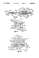
- FIG. 1 is a partially phantomed, simplified respective view of a representative external, hot-plug connection hard disk drive support housing structure embodying principles of the present invention
- FIG. 2 is an enlarged scale partially exploded fragmentary perspective view of an interior sheet metal cage portion of the housing, with one of the tray-supported disk drives removed therefrom;
- FIG. 3 is an enlarged scale partially exploded perspective view of the removed FIG. 2 disk drive and its underlying support tray structure;
- FIG. 4 is an exploded perspective view of a rear end portion of the support tray structure illustrating the snap-fit installation thereon of a printed circuit board connector member
- FIG. 5 is an exploded outer side perspective view of a specially designed support rail structure used to slidably carry the disk drives within the cage;
- FIG. 6 is an exploded perspective view of the support rail structure and a side wall portion of the cage, and illustrates the snap-fit connection between the support rail structure and the cage wall;
- FIG. 7 is a schematic cross-sectional view through one of the support tray structures illustrating the operation of a grounding clip portion of one of its associated support rail structures;
- FIG. 8 is a schematic cross-sectional view through a rear end portion of the cage taken along line 8--8 of FIG. 2 and illustrating the operation of a spaced series of forwardly projecting safety guard plates therein;
- FIGS. 9A-9D are bottom side perspective views of a rear corner portion of one of the disk drive support trays and sequentially illustrate the unique installation and operation thereon of an ejection latch member utilized to facilitate the installation and removal of a disk drive into and from the cage;
- FIGS. 10A and 10B are perspective views of a front end portion of an alternate embodiment of one of the disk drive support trays illustrating a modified latching system thereon in its opened and closed orientations, respectively;
- FIG. 11 is an enlarged scale, simplified partial cross-sectional view through a portion of the modified latching system taken along line 11--11 of FIG. 10B;
- FIG. 12 is an outer side elevational view of an alternate embodiment of the support rail structure of FIG. 5;
- FIG. 13 is an enlarged scale perspective view of a grounding clip portion of the support rail structure of FIG. 12;
- FIG. 14 is a highly schematic top plan view of an alternate embodiment of the printed circuit board connector member shown in FIGS. 3 and 4, together with a hot plug socket to which it is operatively connectable, with certain connector portions of the printed circuit board having been removed therefrom for purposes of illustrative clarity.
- the present invention provides apparatus for removably supporting and providing hot plug connections for a vertical spaced plurality of disk drives 10 (FIG. 2) such as those externally utilized in conjunction with a file server (not shown) or other computer device.
- the support apparatus representatively includes a generally rectangular housing 12 having an open front end 14, and a generally rectangular sheet metal cage structure 16 disposed within the housing.
- Cage 16 has an open front end 18 rearwardly adjacent the housing end 14, top and bottom walls 20 and 22, left and right side walls 24 and 26, and a rear end wall 28 spaced inwardly apart from the rear end wall 30 of housing 12.
- a vertically spaced pair of horizontally elongated hot plug sockets 32 are mounted on the rear cage end wall 28 (FIG. 2).
- three vertically spaced, horizontally elongated rectangular guard plate members 34 project forwardly beyond the rear cage end wall 28, with each of the sockets 32 being disposed between and parallel to a vertically adjacent pair of the plates 34.
- Front end portions of the cage side walls 24,26 are bent to form a pair of vertically extending wall channel portions 36 having generally U-shaped cross-sections along their lengths, and horizontally facing open sides.
- each of the disk drives 10 is supported on the top side of one of a specially designed pair of molded plastic support trays 38 each having a generally rectangular body 40.
- Body 40 has a series of cooling holes 42 formed therethrough; a rear end portion 44 (see FIG. 4); a pair of outwardly projecting opposite side edges 46 rearwardly terminating at rear end portion 44; an upwardly projecting front end plate portion 48 with three LED disk drive activity indicating lights 50 mounted thereon; and a pair of opposite front corner portions 52 projecting outwardly beyond the lower side edge of the front end plate 48.
- Each disk drive 10 is of a conventional construction and has a pair of mounting rail sections 54 extending forwardly and rearwardly along opposite lower side portions thereof. For purposed later described, metal grounding screws 56 are connected to and project outwardly from the mounting rails adjacent their rear ends.
- each disk drive 10 is operatively mounted atop the body portion 40 of its associated support tray 38, the disk drive is positioned between the plate 48 and the rear end portion 44 of the tray body.
- Each disk drive 10 is removably secured to its associated support tray 38 by screws 58 extending upwardly through the tray body and threaded into the bottom side of the disk drive.
- each support tray 38 Mounted atop the rear end portion 44 of each support tray 38 is a small printed circuit board 60 having an elongated rectangular body portion 62 from which a somewhat shorter rectangular plug portion 64 centrally projects in a rearward direction.
- Plum portion 64 has formed on its top side a series of forwardly and rearwardly extending electrically conductive surface traces including grounding traces 66 and signal traces 68.
- the grounding traces 66 extend rearwardly beyond the signal traces 68.
- a slot 78, parallel to the traces 66 and 68, is formed in the circuit board plug portion 64 and functions in a conventional manner to assure the proper orientation of the plug portion when it is operatively inserted into one of the hot plug sockets 32 as later described.
- the circuit board 60 is removably installed on the rear support tray end portion 44 by inserting a front side edge portion 80 of the circuit board body under the abutment tabs 72 and then downwardly pivoting the circuit board 60 to cause the posts 76 to upwardly enter the circuit board body holes 78.
- rear side edge portions 82 of the circuit board body rearwardly deflect the latch portions 74 until hooked upper end portions thereof forwardly snap over top side portions of the circuit board body (see FIG. 3) to releasably lock the circuit board on the rear end portion of the support tray 38.
- opposite end edge portions 90 of the circuit board body 62 define rearward continuations of the side edge portions 46 of the support tray 38.
- various connector pin sections such as the illustrated pin sections 86 and 88, are mounted on the circuit board body 62.
- Pin section 86 is operatively connected to the rear end of the mounted disk drive 10 by a conventional ribbon cable 92
- pin section 88 is operatively connected to the indicating lights 50 by wires 94 (see FIG. 3)
- pin section 88 is operatively connected to the underside of the disk drive 10 by wires 96.
- the wires 94,96 are conveniently routed to the indicating lights 50 and the underside of the disk drive 10 through a wire passage disposed on the top side of the support tray body 40 and generally defined by notches 98 formed in transverse stiffening rib portions 100 of the support tray body, and holding tab portions 102 that overlie the routed wiring.
- each guide channel member 106 has an elongated configuration; a rear end 108; a transversely enlarged front end 110; an outer side 112; an inner side 114; and a generally U-shaped cross-section along its length.
- each guide channel member defines therein a longitudinally extending channel or track 116 that laterally opens through the inner side 114 of the member and vertically widens at the front end of the member to facilitate the slidable insertion therein of a circuit board end edge portion as later described.
- the four guide channel members 106 are arranged in an upper pair removably secured in a parallel, laterally opposing relationship to the inner sides of the cage side walls 24 and 26, and a lower pair removably secured in a parallel, laterally opposing relationship to the inner sides of the cage side walls 24 and 26.
- Guide channel members 106 are releasably snap-fitted onto the cage side walls 24,26 using upper and lower horizontal rows of generally T-shaped openings 118,120,122 formed in each of the cage side walls 24 and 26 (see FIGS. 1, 2 and 6).
- each of the side wall openings 118,120,122 has a vertically enlarged front end portion 124, and a rear end portion 126 that is vertically narrowed by upper and lower portions 128,130 or the particular cage side wall.
- horizontally elongated rectangular openings 132 are formed in the cage side walls 24,26 between each pair of openings 118 and 120, and inturned side wall tab portions 134 are positioned beneath the front ends of the openings 132.
- each of the guide channel members 106 Formed on the outer side of each of the guide channel members 106, and projecting outwardly therefrom, are three longitudinally spaced pairs of upwardly and downwardly extending holding tabs 136 and 138. Between the front two sets of tabs 136,138 the guide channel member has formed thereon a horizontally elongated, inwardly deflectable resilient latch portion 140 laterally projecting outwardly beyond the outer side surface 112 of the guide channel member and having a front end surface 142.
- each guide channel member 106 has two longitudinally spaced pairs 144,146 of ribbed outward projections formed on its top and bottom side edge surfaces. These projections have removably snap-fitted thereon clip member pairs 148,150 projecting inwardly from the outwardly bowed body portion 152 of a resiliently deformable sheet metal grounding clip member 154 positioned on the outer side of the guide channel member as illustrated in FIGS. 5 and 6. Projecting inwardly from the top and bottom side edges of the grounding clip member 154, and respectively overlying the top and bottom side edges of the guide channel member 106, are top and bottom side portions 156 and 158. As illustrated, side portion 156 has upturned front and rear ends, and side portion 158 has downturned front and rear ends.
- each guide channel member 106 is removably snap-fitted onto its associated cage side wall (for example, the illustrated left cage side wall 24) by first outwardly inserting the three tab pairs 136,138 into the enlarged front portions 124 of the side wall openings 118,120,122 as indicated by the dashed arrows in FIG. 6, and pressing the guide channel member against the interior surface of the cage side wall.
- This initial insertion and pressing causes the latch portion 140 to be engaged and inwardly depressed by the side wall 24, and also resiliently bends the clip member body portion 152 against the side wall 24.
- the guide channel member 106 With the guide channel member 106 pressed against the cage side wall, the guide channel member is then rearwardly slid along the side wall until the latch portion 140 snaps outwardly into the side wall opening 132.
- This releasably locks the guide channel member in place on the cage side wall, the front end surface 142 of the latch portion 140 rearwardly overlying the front end surface 162 of the side wall opening 132 and preventing forward movement of the guide channel member relative to the cage, and the rear edge portions of the tab pairs 136,138 abutting the rear end surfaces 164 of the side wall opening portions 126 and preventing rearward movement of the guide channel member relative to the cage.
- Each guide channel member 106 may be quickly removed from the cage 16 simply by depressing the latch portion 140 from the outside of the cage, forwardly sliding the guide channel member along the inner surface of its associated cage side wall, and then removing the tab pairs 136,138 from the front end portions 124 of the side wall openings 118,120 and 122.
- the configuration of each guide channel member 106 makes it reversible--i.e., each guide channel member may be operatively installed on either of the cage side walls 24 and 26. For example, the illustrated FIG.
- guide channel member 106 installed on the left cage side wall 24 can be alternately installed on the right cage side wall 26 simply by removing the guide channel member from the left side wall, rotating the removed guide channel member 180° about its longitudinal axis, and then snapping the guide channel into place on the right cage side wall 26.
- the two tray-mounted disk drives 10 may simply be pushed into place within the cage 16 by inserting opposite end edge portions of the circuit board body portions 62 into the track portions of the upper and lower opposing guide channel pairs and rearwardly sliding the circuit board and tray edge portions along the tracks until the circuit board portions 64 are operatively hot-plugged into their associated sockets 32 at the rear end of the cage. Either of the disk drives 10 may be removed from the cage, without disturbing the operation of the other disk drive, by simply pulling the disk drive rearwardly out of the cage.
- each of the disk drives 10 rearwardly reaches its operating position within the cage 16, the grounding screws 56 projecting outwardly from opposite sides of the disk drive slide under and upwardly engage the upper side portions 156 of the resilient sheet metal grounding clips 154 on the two guide channel members 106 that slidingly support the inserted disk drive.
- This engagement between the grounding screws 56 and the upper grounding clip side portions 156 forms secure and reliable electrical grounding connections between the disk drive and the metal cage structure via the grounding screws and the grounding clips.
- the guide channel member 106 shown in FIG. 7 was installed on cage side wall 26 instead of the illustrated cage wall 24, the clip member side portion 158, and not the side portion 156, would be engaged by one of the grounding screws 56.
- the two metal grounding screws 56 attached to the opposite sides of each of the disk drives 10 provide another useful function in the overall disk drive support apparatus of the present invention--they cooperate with the inturned cage side wall projections 134 (FIG. 6) to prevent the full rearward insertion of either disk drive into the cage in the event that the disk drive is in an improper upside-down orientation Specifically, if either disk drive is turned upside-down and then inserted into the cage, the two disk drive 56 strike and are rearwardly stopped by an associated opposing pair of the inturned side wall portions 134, thereby preventing further rearward insertion of the improperly oriented disk drive into the cage. In turn, this prevents the disk drive circuit board 70 from improperly engaging its associated hot plug socket 32.
- each of the disk drives 10 rearwardly reaches its operative position in which its circuit board 60 is fully inserted into its associated hot plug socket 32, a pair of the forwardly projecting guard plates 34 come into play to block both upper and lower manual access to the circuit board as it approaches its associated hot plug socket, the circuit board passing between the two guard plates as it approaches the socket.
- each ejection latch member 166 is pivotable relative to its associated tray corner portion 52 between an outwardly pivoted dotted line release position and an inwardly pivoted solid line locking position.
- the inner ends of the latch members 166 are provided with hook portions 168 that extend into the interiors of the wall channel portions 36 of the cage structure 16.
- ejection latch members 166 are pivotally and removably secured to the support tray corner portions 52 in a unique manner that avoids the necessity using of connecting screws or rivets, and which will now be described in conjunction with FIGS. 9A-9D.
- each of the support tray corner portions 52 Projecting outwardly from the underside of each of the support tray corner portions 52 are a cylindrical boss 170; an inwardly depressible resilient latch portion 172 having an outer end surface 174; and a cylindrical post 176 having a circular outer end portion 178 from which three circumferentially and equally spaced projections 180 radially outwardly extend.
- the illustrated ejection latch member 166 has a connection plate portion 182 from which the hook portion 168 outwardly extends. Extending outwardly from the plate portion 182 in the opposite direction is a lever plate section 184. Lever plate section 184 has an inner side surface 186 from which a laterally spaced pair of elongated resilient latch portions 188 outwardly extend, outer end sections of the latch portions 188 having facing arcuate notches 190 formed therein.
- a hole 192 is formed transversely through the connection plate portion 182 and is complementarily configured relative to the upper post end 178, the hole having three circumferentially spaced radially outwardly projecting portions through which the upper post end projections 180 may be passed when the upper post end projections 180 and the hole portions 194 are circumferentially aligned.
- Each ejection latch member 166 is pivotally and removably installed on the underside of its associated support tray corner portion 52 in the following manner. Referring first to FIG. 9A, the latch member 166 is oriented as shown so that its connection plate hole 192 is positioned outwardly from the outer post end portion 175 in a manner such that the hole portions 194 are circumferentially aligned with the post end projections 180.
- the latch member connection plate portion 182 is moved inwardly toward and pressed against the underside of the corner portion 52 to cause the post projections 180 to pass through the hole portions 194 and outwardly overlie the connection plate portion 182. With the connection plate portion 182 in its FIG. 9B orientation it contacts and inwardly depresses the corner portion latch 172.
- the latch member 166 While the connection plate portion 182 is held against the support tray corner portion 52, the latch member 166 is rotated a short distance about post 176 in a clockwise direction to move the plate hole portions 194 out of circumferential alignment with the post projections 180 as shown in FIG. 9C. At this point, in which the latch member 166 is in its dotted line position shown in FIG. 2, the latch portion 172 pops back up so that its end surface 174 faces the plate portion edge surface 196, and the latch member 166 is pivotally and captively retained on the support tray corner portion 52.
- the latch member cannot be pivoted in a counterclockwise direction past its FIG. 9C position, to align the hole portions 194 with the post end portions 180 and permit removal of the connecting plate portion 182 from the post 176, unless the latch portion 172 is manually depressed and the latch 166 pivoted back to its FIG. 9B position.
- the latch member 166 may be pivoted in a clockwise direction to its FIG. 9D closed position in which the boss 170 is received within and releasably held between the arcuate notches 190 in the latch portions 188. At this point the latch member is still captively retained on the post 176 since the hole portions 194 have not been rotated far enough to be brought into alignment with the post end portions 180.
- the latch member may be quickly removed from the post 176 simply by rotating the latch member in a counterclockwise direction to its FIG. 9C position, manually depressing the latch 172 and further rotating the latch member to its FIG. 9B position, and then lifting the connecting plate portion 182 off the post 176.
- FIGS. 10A, 10B and 11 An alternate embodiment 38a of the previously described support tray 38 is depicted in FIGS. 10A, 10B and 11.
- FIGS. 10A, 10B and 11 An alternate embodiment 38a of the previously described support tray 38 is depicted in FIGS. 10A, 10B and 11.
- the components of tray 38a similar to those on tray 38 have been given identical reference numerals, but with the subscripts "a".
- connection plate portions 182a are pivotally secured to the front corner portions 52a of the tray body as previously described in conjunction with FIGS. 9A-9D.
- the interlocking cylindrical bosses 170 and latch portions 188 shown in FIGS. 9A-9D are deleted from this embodiment of the support tray structure.
- the latching function of these deleted components is replaced by vertically spaced, generally U-shaped projections 200 formed on the inner sides of the modified ejection lever members 166a, and a pair of resiliently deflectable locking tab portions 202 formed on the tray body corner portions 52a and extending horizontally toward one another in an outwardly spaced relationship with the front end plate 48a of the support tray.
- the top side surfaces of the tabs 202 are provided with downwardly and forwardly sloped portions 203.
- each opposing pair of the projections 200 are transverse side portions 204 that extend toward one another.
- the top transverse side portions 204 of the ejection lever members 166a engage the sloped top side surface portions 203 of the locking tabs 202, cams the tabs 202 downwardly, and then snap into place behind the rear side edges 206 of the tabs 202 as best illustrated in FIG. 11.
- the locking tabs 202 are simply pushed downwardly, as indicated by the arrow 208 in FIG. 11, to permit the top transverse side portion 204 to upwardly clear its associated locking tab 202.
- the facing side surfaces 206 and 210 on the locking tabs 202 and the upper transverse side portions 204 provide a positive abutment lock between the tabs and the ejection lever members 166a.
- the rear side surfaces 206 of the locking tabs 202 are slanted downwardly and forwardly (preferably at an angle of about five degrees) relative to the tray body end wall 48a as best illustrated in FIG. 11.
- the side surfaces 210 of the upper ejection lever member projections 200 are sloped parallel to the side surfaces 206 which they face. This slight sloping of the facing side surfaces 206,210 assists in preventing unintentional unlocking of the ejection lever members 166a from the locking tabs 202 in the event that a leftward force is exerted on the ejection lever members (as viewed in FIG. 11) during, for example, shipping and handling of the assembled housing, cage and disk drive unit.
- the side surface 210 of the lower projection 200 is sloped forwardly and upwardly at the same approximately five degree angle. This permits either of the ejection lever members 166a to be operatively installed on either of the front corner portions 52a of the support tray body.
- FIG. 12 Illustrated in FIG. 12 is an alternate embodiment 106a of the previously described guide channel member 106 shown in FIGS. 5 and 6.
- the modified guide channel member 106a is used in conjunction with a modified circuit board 60a (see FIG. 14) that snaps into place on the rear end of the support tray body in the place of the previously described circuit board 60.
- a modified circuit board 60a see FIG. 14
- components in circuit board 60a similar to those in the circuit board 60 have also been given identical reference numerals, but with the subscripts "a”.
- an opening 212 is formed through the plastic body portion of the guide channel member 106a and extends through its track 116a between the lower projections 146a.
- the opening 212 has a lower side portion that is recessed into the lower side boundary wall of the track 116a.
- the lower projections 146a are spaced further apart than the upper projections 144a.
- the metal grounding clip 154a is also modified relative to the previously described grounding clip 154 in that, in the grounding clip 154a, the lower projections 150a (see FIG. 13) are spaced further apart than the upper projections 148a, and the grounding clip 154a is provided with a central projection 214 having downturned front and rear end portions.
- the modified grounding clip member 154a When the modified grounding clip member 154a is snapped into place on the plastic body of the guide channel member 106a, the upper clip projections 148a snap into the upper body projections 144a, the lower clip projections 150a snap into the lower body projections 146a, and the central clip projection 214 is received in the body opening 212 and extends across the track 116a.
- the opposite ends of the body portion 62a of the printed circuit board 60a have rectangular solder pads 216 formed on their top and bottom sides.
- the ends of the printed circuit board body portion 62a slide rearwardly through the tracks 116a of its associated pair of guide channel members 106a.
- the solder pads 216 on the lower sides of these opposite ends slide across the top side of the central projection 214, thereby electrostatically discharging the circuit board 60a and the disk drive electronics.
- solder pads then rearwardly pass, and become disengaged from the central clip member projection 214.
- the grounding screws 56 (see FIGS. 3 and 7) are brought into engagement with the top clip member side portion 156 and remain in engagement therewith while the disk drive 10 is operatively connected to its associated hot plug at the back of the cage.
- the solder pads again wipe across the central clip member projection 214 to electrostatically discharge the circuit board 60a and the disk drive electronics.
- a series of electrically conductive traces Spaced apart along the length of the plug portion 64a of the circuit board 60a (which is operatively insertable into the illustrated hot plug 32a), and extending along its top side surface toward its rear side edge 218 are a series of electrically conductive traces. From left to right as viewed in FIG. 14 these traces include a grounding trace 220, a voltage trace 222, a pre-charge trace 224 connected to trace 222, and a series of signal traces 226.
- a ground connector 220a coupled to ground
- a voltage connector 222a coupled to a +5V VCC
- a pre-charge connector 224a coupled to the +5V VCC through a resistor 228, and a series of signal connectors 226a.
- grounding trace 220 extends to the rear side edge 218 of the circuit board plug portion 64a, the rear end of the pre-charge tract 224 is rearwardly inset from the side edge 218, the rear end of the voltage trace 222 is further inset from the side edge 218, and the rear ends of the signal traces 226 are still further inset from the rear side edge 218 of the plug portion 64a of the circuit board 60a.
- the voltage trace 222 and the signal traces 226 results in a trace/connector coupling sequence in which (1) the grounding trace 220 is first coupled to its associated grounding connector 220a; (2) the pre-charge trace 224 is then coupled to its associated pre-charge connector 224a; (3) the voltage trace 222 is then coupled to its associated voltage connector 222a; and (4) the signal traces 226 are then simultaneously coupled to their associated signal connectors 226a.
- the circuit board 60a is grounded before any power or signal connections are made thereto. Additionally, the operative electrical connection of the pre-charge trace 224 prior to the electrical connection to the voltage trace 222 serves to prevent disruptive power spikes in the power supply to the multiple disk drive system. It will be appreciated that upon withdrawal of the circuit board plug section 64a from the hot plug 32a, the trace disconnection sequence is reversed relative to their connection sequence so that the trace/connector grounding connection is broken last.
- a series of anti-friction pad sections 222b,224b,226b are formed on the top side of the circuit board plug portion 64a respectively to the rear of the traces 222,224,226.
- the rear ends of the pads 222b,224b,226b are disposed at the rear side edge 218 of the circuit board plug portion 62a, and their front ends are spaced generally equally short distances rearwardly of their associated traces 222,224,226.
- Pads 222b,224b,226b are thus respectively aligned with the connectors 222a,224a,226a.
- Pads 222b,224b,224c are preferably formed from the same electrically conductive material as the traces 220,222,224,226 (for example, gold), and serve to prevent abrasive contact between the circuit board substrate and the connectors 220a,222a,224a,226a.
- disk drive support apparatus representatively described above provides hot plug connections for the disk drives, it will readily be appreciated by those skilled in this art that it could also be employed using non-hot plug socket connections for the disk drives if desired.
Abstract
Description
Claims (18)
Priority Applications (1)
| Application Number | Priority Date | Filing Date | Title |
|---|---|---|---|
| US08/004,696 US5340340A (en) | 1992-09-24 | 1993-01-14 | Apparatus for removably supporting a plurality of hot plug-connected hard disk drives |
Applications Claiming Priority (2)
| Application Number | Priority Date | Filing Date | Title |
|---|---|---|---|
| US07/950,598 US5277615A (en) | 1992-09-24 | 1992-09-24 | Apparatus for removably supporting a plurality of hot plug-connected hard disk drives |
| US08/004,696 US5340340A (en) | 1992-09-24 | 1993-01-14 | Apparatus for removably supporting a plurality of hot plug-connected hard disk drives |
Related Parent Applications (1)
| Application Number | Title | Priority Date | Filing Date |
|---|---|---|---|
| US07/950,598 Continuation-In-Part US5277615A (en) | 1992-09-24 | 1992-09-24 | Apparatus for removably supporting a plurality of hot plug-connected hard disk drives |
Publications (1)
| Publication Number | Publication Date |
|---|---|
| US5340340A true US5340340A (en) | 1994-08-23 |
Family
ID=25490650
Family Applications (3)
| Application Number | Title | Priority Date | Filing Date |
|---|---|---|---|
| US07/950,598 Ceased US5277615A (en) | 1992-09-24 | 1992-09-24 | Apparatus for removably supporting a plurality of hot plug-connected hard disk drives |
| US08/004,696 Expired - Lifetime US5340340A (en) | 1992-09-24 | 1993-01-14 | Apparatus for removably supporting a plurality of hot plug-connected hard disk drives |
| US08/518,164 Expired - Lifetime USRE35915E (en) | 1992-09-24 | 1995-08-23 | Apparatus for removably supporting a plurality of hot plug-connected hard disk drives |
Family Applications Before (1)
| Application Number | Title | Priority Date | Filing Date |
|---|---|---|---|
| US07/950,598 Ceased US5277615A (en) | 1992-09-24 | 1992-09-24 | Apparatus for removably supporting a plurality of hot plug-connected hard disk drives |
Family Applications After (1)
| Application Number | Title | Priority Date | Filing Date |
|---|---|---|---|
| US08/518,164 Expired - Lifetime USRE35915E (en) | 1992-09-24 | 1995-08-23 | Apparatus for removably supporting a plurality of hot plug-connected hard disk drives |
Country Status (5)
| Country | Link |
|---|---|
| US (3) | US5277615A (en) |
| EP (1) | EP0589708B1 (en) |
| AT (1) | ATE201279T1 (en) |
| CA (1) | CA2106626C (en) |
| DE (1) | DE69330224T2 (en) |
Cited By (150)
| Publication number | Priority date | Publication date | Assignee | Title |
|---|---|---|---|---|
| WO1995010206A1 (en) * | 1993-10-12 | 1995-04-20 | Despatch Industries Limited Partnership | Insertion and ejection apparatus for environmental test chambers |
| US5503472A (en) * | 1993-06-29 | 1996-04-02 | Sun Microsystems, Inc. | Method and apparatus for assembly of a multi-disk pack unit |
| US5515515A (en) * | 1993-02-18 | 1996-05-07 | Ast Research, Inc. | Live data storage array system having individually removable, and self-configuring data storage units |
| WO1996016575A1 (en) * | 1994-11-29 | 1996-06-06 | Intel Corporation | Portable disk drive carrier and chassis |
| US5562410A (en) * | 1994-02-10 | 1996-10-08 | Emc Corporation | Self-aligning hot-pluggable fan assembly |
| US5562505A (en) * | 1994-02-01 | 1996-10-08 | Societe Nationale Industrielle Et Aerospatiale | Adaptor for a machine for testing electronic equipment |
| US5600539A (en) * | 1994-10-11 | 1997-02-04 | At&T Global Information Solutions Company | Secure interface card extractor/ejector mechanism |
| US5673172A (en) * | 1996-01-05 | 1997-09-30 | Compaq Computer Corporation | Apparatus for electromagnetic interference and electrostatic discharge shielding of hot plug-connected hard disk drives |
| US5673171A (en) * | 1995-12-05 | 1997-09-30 | Compaq Computer Corporation | Hard disc drive support tray apparatus with built-in handling shock reduction, EMI shielding and mounting alignment structures |
| US5734557A (en) * | 1996-09-13 | 1998-03-31 | Deli U.S.A., L.P. | Mounting assembly for electronic equipment |
| US5757998A (en) * | 1996-10-02 | 1998-05-26 | International Business Machines Corporation | Multigigabit adaptable transceiver module |
| US5758103A (en) * | 1995-08-31 | 1998-05-26 | Samsung Electronics Co., Ltd. | Circuit for replacing a peripheral device of a computer system and method therefor |
| US5790373A (en) * | 1996-09-13 | 1998-08-04 | Silicon Graphics, Inc. | Disk drive loading mechanism |
| US5791753A (en) * | 1996-08-29 | 1998-08-11 | Compaq Computer Corp. | Computer component handle assembly |
| US5806948A (en) * | 1997-06-16 | 1998-09-15 | Rowan, Sr.; W. Frank | Retrofittable battery cabinet for telecommunications enclosures |
| USRE35915E (en) * | 1992-09-24 | 1998-10-06 | Compaq Computer Corporation | Apparatus for removably supporting a plurality of hot plug-connected hard disk drives |
| US5816673A (en) * | 1996-10-11 | 1998-10-06 | Sauer; James P. | Computer chassis assembly |
| US5850296A (en) * | 1995-10-10 | 1998-12-15 | Storm Technology, Inc. | Scanner housing structure |
| US5871264A (en) * | 1998-01-20 | 1999-02-16 | Ohara; Takeyoshi | Structure of drawer type computer housing mounting system |
| EP0898219A1 (en) * | 1997-08-22 | 1999-02-24 | Compaq Computer Corporation | Upgrading a storage media bay |
| US5877939A (en) * | 1997-07-16 | 1999-03-02 | Samsung Electronics Co., Ltd. | Snap door for a household electric appliance |
| US5896273A (en) * | 1996-12-31 | 1999-04-20 | Compaq Computer Corp. | Modular computer chassis interchangeable between stand alone and rack mounted states |
| US5912799A (en) * | 1996-07-01 | 1999-06-15 | Sun Microsystems, Inc. | Multiple disk drive storage enclosure with ventilation |
| US5914855A (en) * | 1997-12-30 | 1999-06-22 | International Business Machines Corporation | Apparatus and method for damping disk drive vibration |
| US5933322A (en) * | 1996-10-23 | 1999-08-03 | Compaq Computer Corporation | Computer docking station with integral base security system |
| US5959841A (en) * | 1996-12-31 | 1999-09-28 | Compaq Computer Corp. | Modular computer chassis with extractor device mounted to the housing |
| US5970030A (en) * | 1997-12-02 | 1999-10-19 | International Business Machines Corporation | Automated data storage library component exchange using media accessor |
| US5986881A (en) * | 1997-11-17 | 1999-11-16 | Hon Hai Precision Ind. Co., Ltd. | Disk driver cage assembly with locking device |
| US5995377A (en) * | 1995-04-12 | 1999-11-30 | Digital Equipment Corporation | Reduced static raid enclosure |
| US6008984A (en) * | 1995-08-04 | 1999-12-28 | Havant International Limited | Disk file mounting |
| US6022224A (en) * | 1998-07-22 | 2000-02-08 | International Business Machines Corporation | Shock mount connector for head disk assembly |
| US6034868A (en) * | 1997-09-15 | 2000-03-07 | Kingston Technology Company | Expansion chassis having a removable wiring bracket and external computer memory |
| WO2000013054A1 (en) * | 1998-09-02 | 2000-03-09 | The Whitaker Corporation | Transceiver housing and ejection mechanism therefore |
| US6035514A (en) * | 1996-10-31 | 2000-03-14 | Hewlett-Packard Company | Guide piece and method for mounting to a chassis in multiple orientations |
| US6046742A (en) * | 1997-05-13 | 2000-04-04 | Micron Electronics, Inc. | Display of system information |
| US6058007A (en) * | 1996-09-24 | 2000-05-02 | Hewlett-Packard Company | Computer with mounting arrangement for optional unit |
| US6058445A (en) * | 1997-05-13 | 2000-05-02 | Micron Electronics, Inc. | Data management method for adding or exchanging components on a running computer |
| US6061232A (en) * | 1997-10-31 | 2000-05-09 | Ho; Ming-Chiao | Supporting bracket assembly for drawer-type hard-disk drive |
| US6068661A (en) * | 1997-10-01 | 2000-05-30 | Micron Electronics, Inc. | Method of emulating synchronous communication |
| US6084768A (en) * | 1998-06-15 | 2000-07-04 | Compaq Computer Corporation | Non-operational shock protection for disk carriers in a high density package |
| US6088221A (en) * | 1998-06-15 | 2000-07-11 | Compaq Computer Corporation | Hot-pluggable disk drive carrier assembly with no loose parts |
| US6105089A (en) * | 1997-05-13 | 2000-08-15 | Micron Electronics, Inc. | Data management system for adding or exchanging components on a running computer |
| US6134615A (en) * | 1997-05-13 | 2000-10-17 | Micron Electronics, Inc. | System for facilitating the replacement or insertion of devices in a computer system through the use of a graphical user interface |
| US6134614A (en) * | 1997-05-13 | 2000-10-17 | Micron Electronics, Inc. | Method for facilitating the replacement or insertion of devices in a computer system through the use of a graphical user interface |
| US6137678A (en) * | 1997-09-30 | 2000-10-24 | Compaq Computer Corporation | Configuring a computer system |
| US6154361A (en) * | 1998-10-02 | 2000-11-28 | International Business Machines Corporation | Disk-drive chassis for reducing transmission of vibrations between disk-drive units of a disk-drive array |
| US6166901A (en) * | 1998-03-13 | 2000-12-26 | International Business Machines Corporation | Vibration dampening system for removable hard disk drive carriers |
| US6186804B1 (en) | 1998-06-29 | 2001-02-13 | Havant International Limited | Mounting and testing of electrical devices using a lever operated bay for receiving the electrical devices |
| US6220456B1 (en) * | 2000-04-19 | 2001-04-24 | Dell Products, L.P. | Method and apparatus for supporting a computer chassis |
| US6227630B1 (en) * | 1998-04-08 | 2001-05-08 | International Business Machines Corporation | Accessory mounting for digital computer |
| US6231224B1 (en) | 1999-09-22 | 2001-05-15 | International Business Machines Corporation | Light pipe guide and carrier for hard disk drive |
| US6233143B1 (en) | 1999-09-22 | 2001-05-15 | International Business Machines Corporation | Shock dampening system for hard disk drive carrier |
| US6247944B1 (en) | 1998-06-15 | 2001-06-19 | Compaq Computer Corporation | Slide-activated, spring-loaded ejector for hot-pluggable disk drive carrier |
| US6292359B1 (en) * | 1999-05-10 | 2001-09-18 | Micron Electronics, Inc. | Component mount |
| US6293636B1 (en) | 1999-12-30 | 2001-09-25 | Gateway, Inc. | Device retention assembly |
| US6299266B1 (en) | 1999-10-12 | 2001-10-09 | Hewlett-Packard Company | Mounting arrangement for computer and other units |
| US6351379B1 (en) * | 2000-08-09 | 2002-02-26 | Lite-On Enclosure Inc. | Extracting and positioning structure for hard disk drive |
| US6351786B2 (en) | 1998-08-24 | 2002-02-26 | Racal Instr Inc | VXI backplane system improvements and methods |
| US6373694B1 (en) * | 2000-08-10 | 2002-04-16 | Inventec Corporation | Fastening device for hard disk |
| US6373696B1 (en) * | 1998-06-15 | 2002-04-16 | Compaq Computer Corporation | Hard drive cooling using finned heat sink and thermally conductive interface pad |
| US6392879B1 (en) * | 2000-03-15 | 2002-05-21 | Compal Electronics, Inc. | Disk drive mounting device for a portable computer |
| US6396686B1 (en) * | 1999-12-09 | 2002-05-28 | Hon Hai Precision Ind. Co., Ltd. | Mounting device for mounting a data storage device |
| US6401475B1 (en) | 2001-04-23 | 2002-06-11 | International Business Machines Corporation | Temperature adjustment module and method using same |
| US6407913B1 (en) | 1999-04-08 | 2002-06-18 | Intel Corporation | Removable carrier for hard disk drive |
| US6425006B1 (en) | 1997-05-13 | 2002-07-23 | Micron Technology, Inc. | Alert configurator and manager |
| US20020104942A1 (en) * | 2000-11-07 | 2002-08-08 | Mimlitch Robert H. | Apparatus and method for adapting two-post rack systems to support four-post rack mounted equipment |
| US6431718B1 (en) * | 1999-09-22 | 2002-08-13 | International Business Machines Corporation | Interconnector and light pipe guide for disk drive and disk drive carrier |
| US6434652B1 (en) * | 1997-11-14 | 2002-08-13 | International Business Machines Corporation | Hot plug subsystem for processor based electrical machine |
| US6442021B1 (en) * | 1998-06-15 | 2002-08-27 | Compaq Computer Corporation | Hot-pluggable disk carrier having enhanced rotational drive vibration control capability |
| US6456489B1 (en) | 2000-05-25 | 2002-09-24 | Gateway, Inc. | Device retention apparatus |
| US6460948B2 (en) * | 1999-10-29 | 2002-10-08 | Hewlett-Packard Company | Drive bracket |
| US6467858B1 (en) | 1999-12-23 | 2002-10-22 | Gateway, Inc. | Computer component retention tray |
| US6474479B2 (en) * | 1996-11-11 | 2002-11-05 | Rittal Electronic Systems Gmbh & Co. Kg | Module rack having at least one front facing groove for mounting components thereto |
| US6480398B1 (en) | 2000-01-05 | 2002-11-12 | Compaq Computer Corporation | CPU easy access panels |
| US6487081B2 (en) | 2000-12-29 | 2002-11-26 | Compaq Information Technologies Group, L.P. | Hard disk drive mounting system and method |
| US20030052580A1 (en) * | 2001-09-19 | 2003-03-20 | Dobler Karl J. | Snap-on slide and rail assembly and method of assembling same |
| US6553416B1 (en) | 1997-05-13 | 2003-04-22 | Micron Technology, Inc. | Managing computer system alerts |
| US6580604B1 (en) | 1997-12-23 | 2003-06-17 | Dell U.S.A., L.P. | Peripheral device bay with adapter plates |
| US6616106B1 (en) | 2002-02-21 | 2003-09-09 | Hewlett-Packard Development Company, L.P. | System and means for the secure mounting of a device bracket |
| US6619766B1 (en) | 1999-10-12 | 2003-09-16 | Gateway, Inc. | Device mounting and retention assembly |
| US6625014B1 (en) | 2002-05-07 | 2003-09-23 | Hewlett-Packard Development Company, L.P. | System and method for situating a disk drive |
| US6666414B2 (en) | 2002-02-21 | 2003-12-23 | Hewlett-Packard Development Company, L.P. | Deformable mounting bracket |
| US20040057201A1 (en) * | 2002-09-20 | 2004-03-25 | Hartung Steven F | Tool-less field replaceable peripheral mounting system |
| US20040120123A1 (en) * | 2002-12-20 | 2004-06-24 | Mayer David W. | Multi-configurable telecommunications rack mounting system and method incorporating same |
| US20040130865A1 (en) * | 2003-01-02 | 2004-07-08 | Vanderheyden William J. | 1U rack mount equipment enclosure with increased structural support |
| KR100433510B1 (en) * | 1996-10-28 | 2004-07-16 | 삼성전자주식회사 | Compter having tool for fixing auxiliary storage to main body |
| US20040159618A1 (en) * | 2003-02-19 | 2004-08-19 | Nguyen Minh H. | Removable rails for use on racks |
| US20040213141A1 (en) * | 2003-04-25 | 2004-10-28 | Lin Ju Shan | Storage device assembly incorporating ejecting mechanism with safety latch |
| US20040219811A1 (en) * | 2003-04-29 | 2004-11-04 | International Business Machines Corporation | Apparatus for positioning an electrical assembly within a housing |
| US20040217073A1 (en) * | 2003-05-01 | 2004-11-04 | Dobler Karl J. | System and method for utilizing a tool-less rail in a rack |
| US20050007747A1 (en) * | 2003-07-11 | 2005-01-13 | Michael Axelrod | Metal electronics device enclosure |
| US20050051672A1 (en) * | 2003-09-04 | 2005-03-10 | Dean Ronald Paul | System and means for the secure mounting of a device bracket |
| US6885550B1 (en) | 1999-08-26 | 2005-04-26 | Axxion Group Corporation | Screw less clip mounted computer drive |
| US20050092727A1 (en) * | 2003-03-20 | 2005-05-05 | Fraley Peter D. | Independent electronics equipment heater using phase width modulation |
| US20050094366A1 (en) * | 2003-10-31 | 2005-05-05 | Lewis Jeffrey M. | Mount for computer drive |
| US20050130034A1 (en) * | 2003-05-28 | 2005-06-16 | One World Technologies Limited | Slide type battery ejection mechanism |
| US20050194287A1 (en) * | 2004-03-05 | 2005-09-08 | Chun-Yi Lien | Extendable tray structure |
| US6955549B2 (en) * | 2003-05-28 | 2005-10-18 | One World Technologies Limited | Slide type battery ejection mechanism |
| US6962397B2 (en) | 2001-09-19 | 2005-11-08 | Hewlett-Packard Development Company, L.P. | Expandable slide and rail assembly for a rack |
| US6972948B1 (en) * | 2003-09-05 | 2005-12-06 | New Gerald W | Computer drawer assembly |
| US20050270737A1 (en) * | 2004-06-07 | 2005-12-08 | Sun Microsystems, Inc. | Drive carrier |
| US6988626B2 (en) | 1998-07-31 | 2006-01-24 | Varghese Paily T | Computer component rack mounting arrangement |
| US20060045943A1 (en) * | 2004-08-31 | 2006-03-02 | Manuel Calzada | Food tray |
| US7083444B1 (en) * | 2005-03-14 | 2006-08-01 | International Business Machines Corporation | Daughterboard with sense and release system |
| US20060238988A1 (en) * | 2005-04-26 | 2006-10-26 | Dell Products L.P. | Method and apparatus for coupling a modular component to a chassis |
| US7134558B1 (en) * | 2002-03-14 | 2006-11-14 | Innovation First, Inc. | Universal rack mountable shelf |
| US20070025067A1 (en) * | 2005-07-28 | 2007-02-01 | Inventec Corporation | Supporting mechanism for storage drives |
| US7201279B1 (en) | 2002-07-18 | 2007-04-10 | Innovation First, Inc. | Sliding rack-mountable shelf for rack-mountable components |
| US20070167071A1 (en) * | 2006-01-13 | 2007-07-19 | Hon Hai Precision Industry Co., Ltd. | Mounting apparatus for circuit board |
| US20080080129A1 (en) * | 2006-10-02 | 2008-04-03 | Dell Products L.P. | Interposer For A Drive Bay |
| US20080128569A1 (en) * | 2006-12-01 | 2008-06-05 | Hon Hai Precision Industry Co., Ltd. | Drive bracket assembly |
| DE10392655B4 (en) * | 2002-10-26 | 2008-06-19 | Humax Co.Ltd., Seongnam | Digital Broadcasting Receiver with the Removable Storage Device and the Storage Method of the Digital broadcasting Program |
| US20080180918A1 (en) * | 2007-01-25 | 2008-07-31 | Bruce Edwin Baker | Apparatus for positioning electronic component modules within an equipment chassis |
| CN100449472C (en) * | 2006-09-08 | 2009-01-07 | 华为技术有限公司 | Method and apparatus for treating disc hot insert |
| US20090257186A1 (en) * | 2008-04-11 | 2009-10-15 | John Dunham | Horizontal drive drawer system and method |
| CN101562319A (en) * | 2008-04-18 | 2009-10-21 | 菲尼克斯电气公司 | Fastening device for detachable holding of an electrical distributor by latching |
| US20100172086A1 (en) * | 2009-01-05 | 2010-07-08 | Hong Fu Jin Precision Industry (Shenzhen) Co., Ltd | Mounting apparatus for disk drive |
| US20100277874A1 (en) * | 2009-05-04 | 2010-11-04 | Soares Itamar F | Communication protocol interface module |
| DE202011003479U1 (en) | 2010-03-19 | 2011-05-19 | Friedrich-Schiller-Universität Jena, 07743 | Structured silicon layer for an optoelectronic component and optoelectronic component |
| US20110249385A1 (en) * | 2010-04-07 | 2011-10-13 | Hon Hai Precision Industry Co., Ltd. | Expansion card supporting structure |
| US20110297628A1 (en) * | 2010-06-08 | 2011-12-08 | Hon Hai Precision Industry Co., Ltd. | Server rack assembly |
| US20120182671A1 (en) * | 2011-01-14 | 2012-07-19 | Chicony Power Technology Co., Ltd. | Swapping apparatus of electronic device |
| US8385076B2 (en) * | 2010-06-28 | 2013-02-26 | Hong Fu Jin Precision Industry (Shenzhen) Co., Ltd. | Electronic device with pivotable arm |
| US20130201626A1 (en) * | 2012-02-02 | 2013-08-08 | Thomas Aaron Bondurant | Clips and latch to receive a computing component |
| US20130279129A1 (en) * | 2012-04-23 | 2013-10-24 | Wistron Corporation | Storage device assembling module and electronic apparatus using the same |
| CN103823517A (en) * | 2012-11-19 | 2014-05-28 | 英业达科技有限公司 | Hard disk frame and server |
| US8758040B2 (en) * | 2012-11-29 | 2014-06-24 | Eaton Corporation | Systems and methods for aligning and connecting electrical components |
| US20150014912A1 (en) * | 2013-07-02 | 2015-01-15 | Atlas Sound Lp | Electronic module installation tools for electronic racks |
| US20150091423A1 (en) * | 2013-09-30 | 2015-04-02 | Wistron Corp. | Carrying device and self-locking structure thereof |
| USD736770S1 (en) * | 2014-03-05 | 2015-08-18 | Inx8 Inc. | Drive carrier for external storage enclosure |
| US20160105987A1 (en) * | 2014-10-14 | 2016-04-14 | Hon Hai Precision Industry Co., Ltd. | Slide rail interlocking apparatus and electronic device having the same |
| US20160147258A1 (en) * | 2007-09-04 | 2016-05-26 | Apple Inc. | Method for assembling an electronic device |
| US20170220080A1 (en) * | 2016-01-28 | 2017-08-03 | Hewlett Packard Enterprise Development Lp | Securing an expansion card in a computing device |
| US10111358B2 (en) * | 2017-02-20 | 2018-10-23 | Super Micro Computer Inc. | Server device |
| US10366030B2 (en) | 2014-12-18 | 2019-07-30 | Hewlett Packard Enterprise Development Lp | Storage drive adapter |
| US20190252004A1 (en) * | 2018-02-13 | 2019-08-15 | Wistron Corp. | Casing and computer including the same |
| US20190333544A1 (en) * | 2017-08-07 | 2019-10-31 | Zhengzhou Yunhai Information Technology Co., Ltd. | Tool-less quick assembly and disassembly device for hard disk module |
| US10706894B1 (en) * | 2019-01-09 | 2020-07-07 | Super Micro Computer Inc. | Data storage device for server |
| US10939573B1 (en) * | 2019-08-28 | 2021-03-02 | Dell Products, L.P. | Electronic module carrier for an information handling system |
| US10939574B2 (en) * | 2019-06-14 | 2021-03-02 | Wistron Corporation | Server apparatus and tray mechanism thereof |
| US20210091489A1 (en) * | 2017-12-22 | 2021-03-25 | Ting-Jui Wang | Quick release connecting device |
| US10986747B2 (en) * | 2019-08-27 | 2021-04-20 | Wistron Corp. | Fixing assembly, casing assembly, and electronic device |
| US10993346B2 (en) * | 2019-07-29 | 2021-04-27 | Wistron Corporation | Electronic device capable of installing different modules and case module thereof |
| CN113782064A (en) * | 2020-06-09 | 2021-12-10 | 英业达科技有限公司 | Hard disk fixing assembly |
| US11224139B2 (en) * | 2019-03-22 | 2022-01-11 | Fanuc Corporation | Circuit board fall-out prevention structure and numerical control device |
| US20220087043A1 (en) * | 2020-09-16 | 2022-03-17 | Wistron Corp. | Electronic device and board module thereof |
| US11297728B1 (en) * | 2020-09-23 | 2022-04-05 | Dell Products, L.P. | Carrier supporting nested, replaceable hardware components |
| US11372788B2 (en) * | 2015-12-07 | 2022-06-28 | Eaton Intelligent Power Limited | Bus arrangement and method for operating a bus arrangement |
| US20230085694A1 (en) * | 2021-09-23 | 2023-03-23 | Wiwynn Corporation | Unlock mechanism and server |
| USD1019337S1 (en) * | 2021-09-17 | 2024-03-26 | Wiwynn Corporation | Handle |
Families Citing this family (184)
| Publication number | Priority date | Publication date | Assignee | Title |
|---|---|---|---|---|
| JP2752247B2 (en) * | 1990-11-29 | 1998-05-18 | 富士通株式会社 | Information storage device |
| US5483419A (en) * | 1991-09-24 | 1996-01-09 | Teac Corporation | Hot-swappable multi-cartridge docking module |
| JPH07176168A (en) | 1991-09-24 | 1995-07-14 | Kalok Corp | Large-capacity thin disk drive system, disk drive assembly and assembly method |
| US5596738A (en) * | 1992-01-31 | 1997-01-21 | Teac Corporation | Peripheral device control system using changeable firmware in a single flash memory |
| EP0558770A1 (en) * | 1992-02-29 | 1993-09-08 | International Business Machines Corporation | A hot pluggable electrical circuit |
| US5507650A (en) * | 1992-11-16 | 1996-04-16 | Hjs & E Engineering | Universal slide mounted adaptor for storage devices |
| JP2567629Y2 (en) | 1993-03-23 | 1998-04-02 | バーグ・テクノロジー・インコーポレーテッド | Connector device |
| US5653518A (en) * | 1993-09-10 | 1997-08-05 | Compaq Computer Corporation | Quick release drive unit rail members |
| US5564804A (en) * | 1993-12-17 | 1996-10-15 | Silicon Graphics, Inc. | Disk drive bracket |
| US5530302A (en) * | 1994-01-13 | 1996-06-25 | Network Systems Corporation | Circuit module with hot-swap control circuitry |
| US5481431A (en) * | 1994-01-28 | 1996-01-02 | Sun Microsystems, Inc. | System having U-shaped actuator and handle with cam surfaces for mounting computer hard drive or the like |
| US5527104A (en) * | 1994-04-06 | 1996-06-18 | Dell Usa, L. P. | Computer chassis cover alignment apparatus |
| US5557499A (en) * | 1994-06-28 | 1996-09-17 | Ast Research, Inc. | Hard-disk drive tray assembly with pivotally rotatable front bezel |
| US5594627A (en) * | 1994-06-28 | 1997-01-14 | Ast Research, Inc. | Circuit card retainer |
| US5579491A (en) * | 1994-07-07 | 1996-11-26 | Dell U.S.A., L.P. | Local proactive hot swap request/acknowledge system |
| US5587877A (en) * | 1994-10-26 | 1996-12-24 | Amco Engineering Co. | Computer organizer enclosure and method |
| US5574865A (en) * | 1994-12-01 | 1996-11-12 | Unisys Corporation | System for data transfer protection during module connection/disconnection onto live bus |
| US5713747A (en) | 1995-01-06 | 1998-02-03 | Berg Technology, Inc. | Memory card connector |
| EP0801823B1 (en) * | 1995-01-06 | 2003-05-02 | Fci | Shielded memory card connector |
| US5625238A (en) * | 1995-02-03 | 1997-04-29 | Motorola, Inc. | Apparatus for non-disruptively interconnecting perpheral device modules with a host device |
| JP2658954B2 (en) * | 1995-03-23 | 1997-09-30 | 日本電気株式会社 | Disk drive unit for magnetic disk drive |
| US5668697A (en) * | 1995-04-20 | 1997-09-16 | Hewlett-Packard Company | Data storage module having cradles on housing and elastomeric member mounted on data storage mechanism |
| US5668696A (en) * | 1995-07-10 | 1997-09-16 | Dell Usa, L.P. | Carrier-based mounting structure for computer peripheral chassis |
| EP0757351B1 (en) * | 1995-07-31 | 2001-08-16 | Hewlett-Packard Company, A Delaware Corporation | Computer frame structure with modular housings |
| US6059586A (en) * | 1995-09-12 | 2000-05-09 | The Whitaker Corporation | Memory card connector |
| US5595501A (en) * | 1995-09-29 | 1997-01-21 | Ho; Hsin C. | Sliding case mounting device |
| US5654873A (en) * | 1996-01-29 | 1997-08-05 | Silicon Graphics, Inc. | Single connector attachment drive sled assembly having light pipe coupled to a rail |
| DE19603092C1 (en) * | 1996-01-29 | 1997-04-30 | Siemens Nixdorf Inf Syst | Disc drive insert especially for 'hot-replace' function |
| USD379623S (en) * | 1996-02-12 | 1997-06-03 | Jeff Wu | Computer housing |
| US5805420A (en) * | 1996-04-09 | 1998-09-08 | Scitex Digital Video, Inc. | Mounting assembly for removable installation of electronic components into a housing |
| US5797767A (en) * | 1996-05-31 | 1998-08-25 | Berg Technology, Inc. | Indicator light modular jack |
| US5761030A (en) * | 1996-06-19 | 1998-06-02 | Compaq Computer Corporation | Electronic device with circuit board latching and retaining structure |
| US6240058B1 (en) * | 1996-07-11 | 2001-05-29 | Nsm Aktiengesellschaft | Disk-changing unit with modular design |
| DE69612747T2 (en) * | 1996-10-03 | 2001-08-23 | Hewlett Packard Co | Mounting arrangement for fastening a system unit |
| US6049451A (en) * | 1996-11-14 | 2000-04-11 | Dell Usa, L.P. | Mounting rail retaining pin aperture |
| US6088222A (en) * | 1996-11-14 | 2000-07-11 | Dell Usa, L.P. | Computer peripheral chassis frame structure having a split lance for location, electrical grounding, and load bearing of chassis carriers |
| DE19718173C2 (en) * | 1997-04-29 | 1999-03-18 | Siemens Nixdorf Inf Syst | Device for protecting a computer system against unauthorized pulling of a hardware component |
| SG79940A1 (en) * | 1997-05-02 | 2001-04-17 | Chen Chih Kung | A grounding structure for extractable harddisk |
| US6499073B1 (en) | 1997-05-13 | 2002-12-24 | Micron Electronics, Inc. | System using programmable processor for selectively enabling or disabling power to adapter in response to respective request signals |
| US6179486B1 (en) | 1997-05-13 | 2001-01-30 | Micron Electronics, Inc. | Method for hot add of a mass storage adapter on a system including a dynamically loaded adapter driver |
| US6330690B1 (en) | 1997-05-13 | 2001-12-11 | Micron Electronics, Inc. | Method of resetting a server |
| US6418492B1 (en) | 1997-05-13 | 2002-07-09 | Micron Electronics | Method for computer implemented hot-swap and hot-add |
| US6338150B1 (en) * | 1997-05-13 | 2002-01-08 | Micron Technology, Inc. | Diagnostic and managing distributed processor system |
| US6219734B1 (en) | 1997-05-13 | 2001-04-17 | Micron Electronics, Inc. | Method for the hot add of a mass storage adapter on a system including a statically loaded adapter driver |
| US6249834B1 (en) | 1997-05-13 | 2001-06-19 | Micron Technology, Inc. | System for expanding PCI bus loading capacity |
| US6269412B1 (en) | 1997-05-13 | 2001-07-31 | Micron Technology, Inc. | Apparatus for recording information system events |
| US6243773B1 (en) | 1997-05-13 | 2001-06-05 | Micron Electronics, Inc. | Configuration management system for hot adding and hot replacing devices |
| US6202160B1 (en) | 1997-05-13 | 2001-03-13 | Micron Electronics, Inc. | System for independent powering of a computer system |
| US6170028B1 (en) | 1997-05-13 | 2001-01-02 | Micron Electronics, Inc. | Method for hot swapping a programmable network adapter by using a programmable processor to selectively disabling and enabling power thereto upon receiving respective control signals |
| US6363497B1 (en) | 1997-05-13 | 2002-03-26 | Micron Technology, Inc. | System for clustering software applications |
| US5892928A (en) * | 1997-05-13 | 1999-04-06 | Micron Electronics, Inc. | Method for the hot add of a network adapter on a system including a dynamically loaded adapter driver |
| US6163853A (en) * | 1997-05-13 | 2000-12-19 | Micron Electronics, Inc. | Method for communicating a software-generated pulse waveform between two servers in a network |
| US6253334B1 (en) | 1997-05-13 | 2001-06-26 | Micron Electronics, Inc. | Three bus server architecture with a legacy PCI bus and mirrored I/O PCI buses |
| US6195717B1 (en) | 1997-05-13 | 2001-02-27 | Micron Electronics, Inc. | Method of expanding bus loading capacity |
| US6163849A (en) * | 1997-05-13 | 2000-12-19 | Micron Electronics, Inc. | Method of powering up or powering down a server to a maintenance state |
| US6249885B1 (en) | 1997-05-13 | 2001-06-19 | Karl S. Johnson | Method for managing environmental conditions of a distributed processor system |
| US6243838B1 (en) | 1997-05-13 | 2001-06-05 | Micron Electronics, Inc. | Method for automatically reporting a system failure in a server |
| US6173346B1 (en) | 1997-05-13 | 2001-01-09 | Micron Electronics, Inc. | Method for hot swapping a programmable storage adapter using a programmable processor for selectively enabling or disabling power to adapter slot in response to respective request signals |
| US6192434B1 (en) | 1997-05-13 | 2001-02-20 | Micron Electronics, Inc | System for hot swapping a programmable adapter by using a programmable processor to selectively disabling and enabling power thereto upon receiving respective control signals |
| US6189109B1 (en) | 1997-05-13 | 2001-02-13 | Micron Electronics, Inc. | Method of remote access and control of environmental conditions |
| US6269417B1 (en) | 1997-05-13 | 2001-07-31 | Micron Technology, Inc. | Method for determining and displaying the physical slot number of an expansion bus device |
| US6202111B1 (en) | 1997-05-13 | 2001-03-13 | Micron Electronics, Inc. | Method for the hot add of a network adapter on a system including a statically loaded adapter driver |
| US6324608B1 (en) * | 1997-05-13 | 2001-11-27 | Micron Electronics | Method for hot swapping of network components |
| US6304929B1 (en) | 1997-05-13 | 2001-10-16 | Micron Electronics, Inc. | Method for hot swapping a programmable adapter by using a programmable processor to selectively disabling and enabling power thereto upon receiving respective control signals |
| US6292905B1 (en) | 1997-05-13 | 2001-09-18 | Micron Technology, Inc. | Method for providing a fault tolerant network using distributed server processes to remap clustered network resources to other servers during server failure |
| US6145098A (en) | 1997-05-13 | 2000-11-07 | Micron Electronics, Inc. | System for displaying system status |
| US6247080B1 (en) | 1997-05-13 | 2001-06-12 | Micron Electronics, Inc. | Method for the hot add of devices |
| US6249828B1 (en) | 1997-05-13 | 2001-06-19 | Micron Electronics, Inc. | Method for the hot swap of a mass storage adapter on a system including a statically loaded adapter driver |
| US5949645A (en) * | 1997-06-02 | 1999-09-07 | Northern Telecom Limited | Electronic unit |
| US5973918A (en) * | 1997-06-16 | 1999-10-26 | Compaq Computer Corporation | Aligned pivoting power supply tray and guided input/output tray for connection of the power supply and input/output to the computer motherboard |
| US5978821A (en) * | 1997-09-17 | 1999-11-02 | Automated Business Companies | Smart modular electronic machine |
| US6138179A (en) * | 1997-10-01 | 2000-10-24 | Micron Electronics, Inc. | System for automatically partitioning and formatting a primary hard disk for installing software in which selection of extended partition size is not related to size of hard disk |
| US6263387B1 (en) | 1997-10-01 | 2001-07-17 | Micron Electronics, Inc. | System for automatically configuring a server after hot add of a device |
| US6199173B1 (en) | 1997-10-01 | 2001-03-06 | Micron Electronics, Inc. | Method for mapping environmental resources to memory for program access |
| US6212585B1 (en) | 1997-10-01 | 2001-04-03 | Micron Electronics, Inc. | Method of automatically configuring a server after hot add of a device |
| US6175490B1 (en) | 1997-10-01 | 2001-01-16 | Micron Electronics, Inc. | Fault tolerant computer system |
| US6272010B1 (en) | 1998-01-27 | 2001-08-07 | Dell Usa, L.P. | Peripheral device mounting apparatus |
| US6799224B1 (en) | 1998-03-10 | 2004-09-28 | Quad Research | High speed fault tolerant mass storage network information server |
| US6260155B1 (en) | 1998-05-01 | 2001-07-10 | Quad Research | Network information server |
| US6788997B1 (en) * | 1998-06-01 | 2004-09-07 | Medselect, Inc. | Medical cabinet with adjustable drawers |
| US6178091B1 (en) * | 1998-07-09 | 2001-01-23 | Dell Usa, L.P. | Computer system having surface mount PWB grounding clips |
| US6205503B1 (en) | 1998-07-17 | 2001-03-20 | Mallikarjunan Mahalingam | Method for the hot swap and add of input/output platforms and devices |
| US6223234B1 (en) | 1998-07-17 | 2001-04-24 | Micron Electronics, Inc. | Apparatus for the hot swap and add of input/output platforms and devices |
| US6058016A (en) * | 1998-09-10 | 2000-05-02 | International Business Machines Corporation | Direct dock storage device carrier |
| AU1104600A (en) * | 1998-10-13 | 2000-05-01 | Avid Technology, Inc. | Disk drive enclosure |
| EP1163570A4 (en) * | 1999-02-19 | 2007-12-19 | Gen Dynamics Inf Systems Inc | Data storage housing |
| US6325353B1 (en) * | 1999-03-08 | 2001-12-04 | Intel Corporation | Carrier for disk drive hot swapping |
| US6256204B1 (en) * | 1999-03-19 | 2001-07-03 | International Business Machines Corporation | Injection molded disk drive carrier with integral latch and wire form retention |
| US6275382B1 (en) | 1999-04-13 | 2001-08-14 | Dell Usa, L.P. | Apparatus for mounting a peripheral device in a computer system |
| GB2349012B (en) * | 1999-04-17 | 2003-05-28 | John Knott | Electronic apparatus |
| US7271999B2 (en) * | 1999-05-11 | 2007-09-18 | Josef Rabinovitz | Enclosure for computer peripheral devices |
| WO2000074454A1 (en) * | 1999-05-31 | 2000-12-07 | Fujitsu Limited | Communication device and plug unit |
| US6359836B1 (en) * | 1999-06-09 | 2002-03-19 | Hewlett-Packard Company | Locking isolation mounting system for data storage modules |
| US6236563B1 (en) * | 1999-06-30 | 2001-05-22 | Dell Usa, L.P. | Retention apparatus for a peripheral device |
| US6370022B1 (en) * | 1999-07-13 | 2002-04-09 | Gateway, Inc. | Screwless computer drive assembly |
| US6560102B1 (en) | 2000-10-23 | 2003-05-06 | Belkin Components | Universal serial bus docking station |
| US6304439B1 (en) | 1999-08-30 | 2001-10-16 | Connex, Total Technologies, Inc. | Disk drive sled insertion and removal system |
| US6320749B1 (en) * | 1999-08-30 | 2001-11-20 | John W. Ayres | Zero height power unit shelf system |
| US6385036B1 (en) * | 1999-09-10 | 2002-05-07 | Robert C. Chien | Screwless computer case assembly |
| US6304440B1 (en) * | 1999-11-04 | 2001-10-16 | Liken Lin | Shock-proof device of external hard disk driver box |
| US6377448B1 (en) * | 1999-11-08 | 2002-04-23 | Hon Hai Precision Ind. Co., Ltd. | Device housing with a grounding clip |
| US6337793B1 (en) | 1999-11-23 | 2002-01-08 | Dell Usa, L.P. | Apparatus and method for mounting a peripheral device in a computer system |
| US6381139B1 (en) * | 1999-12-30 | 2002-04-30 | Silicon Graphics, Inc. | Carrier for computer peripheral device |
| US6685033B1 (en) | 2000-03-03 | 2004-02-03 | Dell Products L.P. | System and apparatus enabling top, front and rear access to a rack mounted computer device |
| US6310769B1 (en) | 2000-05-03 | 2001-10-30 | Dell Products L.P. | Mounting bracket assembly for system components in a computer |
| US7263476B1 (en) * | 2000-06-12 | 2007-08-28 | Quad Research | High speed information processing and mass storage system and method, particularly for information and application servers |
| US6452793B1 (en) * | 2001-01-26 | 2002-09-17 | Micron Technology, Inc. | Apparatuses and methods for preventing disengagement of electrical connectors in the assembly of computers |
| US6525933B2 (en) | 2001-01-31 | 2003-02-25 | Hewlett-Packard Company | Computer peripheral mounting bracket |
| US6529374B2 (en) * | 2001-02-26 | 2003-03-04 | Teac Corporation | Electronic apparatus |
| GB2372872A (en) * | 2001-03-03 | 2002-09-04 | John Eric Dowell | Computer hard drive rack |
| US6532150B2 (en) | 2001-05-31 | 2003-03-11 | American Megatrends, Inc. | Disk drive carrier apparatus and associated method |
| US6616252B2 (en) * | 2001-07-30 | 2003-09-09 | Hewlett-Packard Development Company, L.P. | Permanently attached rackmount handles and spacing brackets |
| US20030033463A1 (en) * | 2001-08-10 | 2003-02-13 | Garnett Paul J. | Computer system storage |
| US6746254B2 (en) | 2001-08-10 | 2004-06-08 | Axxion Group Corporation | Screwless circuit board attachment |
| US6618254B2 (en) | 2001-09-05 | 2003-09-09 | Hewlett-Packard Development Company, L.P. | Methods and apparatus for securing disk drives in a disk array |
| US6614653B2 (en) | 2001-10-03 | 2003-09-02 | International Business Machines Corporation | Disk drive insertion tool and method |
| US7167372B2 (en) * | 2003-08-26 | 2007-01-23 | Belkin Corporation | Universal serial bus hub and method of manufacturing same |
| US6867966B2 (en) | 2002-05-31 | 2005-03-15 | Verari Systems, Inc. | Method and apparatus for rack mounting computer components |
| US6801428B2 (en) | 2002-05-31 | 2004-10-05 | Racksaver, Inc. | Rack mountable computer component fan cooling arrangement and method |
| US6836030B2 (en) * | 2002-05-31 | 2004-12-28 | Verari Systems, Inc. | Rack mountable computer component power distribution unit and method |
| US6909611B2 (en) * | 2002-05-31 | 2005-06-21 | Verari System, Inc. | Rack mountable computer component and method of making same |
| TW566593U (en) * | 2002-07-10 | 2003-12-11 | Cheng-Chun Chang | Dual-interface external computer connection box |
| US20040057216A1 (en) * | 2002-09-25 | 2004-03-25 | Smith John V. | Electronic component rack assembly and method |
| US7329152B2 (en) * | 2003-08-26 | 2008-02-12 | Belkin International, Inc. | Universal serial bus hub and method of manufacturing same |
| US8014170B2 (en) | 2003-08-26 | 2011-09-06 | Belkin International, Inc. | Cable management device and method of cable management |
| US20050152061A1 (en) * | 2003-10-31 | 2005-07-14 | Havard Hoelsaeter | Configurable storage system with swappable tape magazines and hard-disk magazines |
| TWM250209U (en) * | 2004-01-20 | 2004-11-11 | Quanta Comp Inc | Slidable motherboard tray structure |
| US7634784B2 (en) * | 2004-04-08 | 2009-12-15 | Hewlett-Packard Development Company, L.P. | Data storage means |
| US7215506B2 (en) * | 2004-06-30 | 2007-05-08 | Hitachi Global Storage Technologies Netherlands B.V. | Hard disk drive (HDD) assembly of small form-factor HDD shock-mounted in frame having dimensions of larger form-factor HDD |
| US7428742B2 (en) * | 2004-09-09 | 2008-09-23 | Victor Chuan-Chen Wu | Mass storage cradle device |
| US7362565B2 (en) * | 2004-09-21 | 2008-04-22 | Dot Hill Systems Corporation | Disk drive support system |
| US20060243472A1 (en) * | 2005-04-28 | 2006-11-02 | Datavan International Corp. | [mainframe mounting structure] |
| US7806723B2 (en) * | 2007-01-05 | 2010-10-05 | Belkin International, Inc. | Electrical grommet device |
| US7381095B2 (en) * | 2005-06-20 | 2008-06-03 | Belkin International, Inc. | Multi-standard connection hub and method of manufacturing same |
| CN100489731C (en) * | 2005-09-30 | 2009-05-20 | 鸿富锦精密工业(深圳)有限公司 | Pin of cradle server |
| US7447011B2 (en) * | 2005-12-01 | 2008-11-04 | Xyratex Technology Limited | Data storage device carrier and carrier tray |
| US7835154B2 (en) * | 2006-06-30 | 2010-11-16 | Siemens Industry, Inc. | Electronic module having a locking member and system including same |
| TWI409804B (en) * | 2006-07-17 | 2013-09-21 | Xyratex Tech Ltd | Dongles and methods of manufacturing a dongle |
| DE102006034402B3 (en) * | 2006-07-25 | 2007-12-20 | Fujitsu Siemens Computers Gmbh | Mounting frame for regulating computer component, has two side parts, computer component and heading section fixed with side parts, where pivoted unlocking lever is arranged at frame |
| US7525796B2 (en) * | 2006-11-29 | 2009-04-28 | Foreshot Industrial Corporation | Storage device |
| US7990724B2 (en) | 2006-12-19 | 2011-08-02 | Juhasz Paul R | Mobile motherboard |
| US20080239650A1 (en) * | 2007-03-28 | 2008-10-02 | International Business Machines Corporation | Mounting electronic components |
| US7782603B2 (en) * | 2007-03-28 | 2010-08-24 | International Business Machines Corporation | Tool-less electronic component retention |
| JP4697191B2 (en) * | 2007-06-12 | 2011-06-08 | トヨタ自動車株式会社 | Electrical device connector structure and vehicle |
| US8050027B2 (en) * | 2007-07-05 | 2011-11-01 | Ablecom Technology Incorporated | Data cartridge device for computer equipment |
| US7601026B2 (en) * | 2007-07-31 | 2009-10-13 | Hitachi Global Storage Technologies Netherlands B.V. | Card-through-connector fastener for reducing connector distortion |
| US20110043986A1 (en) * | 2008-04-30 | 2011-02-24 | Conn Kevin D | Power supply assembly for server rack and method for mounting power supply for server rack |
| US20100110628A1 (en) * | 2008-10-30 | 2010-05-06 | Mark Barrenechea | Apparatus and Method for Enhancing the Maintainability and Cooling of Computer Components on Trays in a Cabinet |
| US8441786B2 (en) * | 2009-09-22 | 2013-05-14 | Jabil Circuit, Inc. | Electronic connectors and form factor adapters for electronic components |
| CN102081952B (en) * | 2009-11-27 | 2015-04-15 | 中山市云创知识产权服务有限公司 | Hard disk fixing device |
| CN102136912B (en) * | 2010-01-25 | 2013-06-05 | 鸿富锦精密工业(深圳)有限公司 | Plug device and communication equipment using same |
| TWI383733B (en) * | 2010-01-26 | 2013-01-21 | Hon Hai Prec Ind Co Ltd | Handle assembly and communication device |
| EP2378388A1 (en) * | 2010-04-13 | 2011-10-19 | Siemens Aktiengesellschaft | Computer with a housing and a storage drive |
| CN102236384A (en) * | 2010-04-23 | 2011-11-09 | 鸿富锦精密工业(深圳)有限公司 | Electronic device combination |
| KR101255340B1 (en) * | 2010-11-16 | 2013-04-16 | 도시바삼성스토리지테크놀러지코리아 주식회사 | Multimedia device |
| AT511424B1 (en) * | 2011-04-26 | 2014-06-15 | Zizala Lichtsysteme Gmbh | LOCKING DEVICE FOR CONNECTING COMPONENTS |
| US8644017B2 (en) | 2011-05-26 | 2014-02-04 | Lsi Corporation | Storage device carriers for adapting a storage device of a first size to a slot for a storage device of a second size |
| US8717752B2 (en) | 2011-06-28 | 2014-05-06 | Lsi Corporation | Drive enclosures for tool-less removable mounting of solid state drives onto printed circuit board devices |
| TWM436911U (en) * | 2012-02-10 | 2012-09-01 | Cal Comp Electronics & Comm Co | Network attached storage device |
| US10015900B2 (en) * | 2012-03-20 | 2018-07-03 | Brocade Communications Systems LLC | Compact flash retainer |
| TWI548329B (en) * | 2012-06-07 | 2016-09-01 | Tseng Ching Chao | Active ear holder and equipment auxiliary replacement device |
| CN103533799B (en) * | 2012-07-06 | 2016-08-17 | 曾庆照 | Activity ear mount and comprise the equipment auxiliary replacement device of this activity ear mount |
| TW201414405A (en) * | 2012-09-20 | 2014-04-01 | Hon Hai Prec Ind Co Ltd | Supporting apparatus |
| US9320169B2 (en) * | 2013-07-03 | 2016-04-19 | Dell Products, L.P. | Modular dense storage array |
| USD736769S1 (en) * | 2014-03-05 | 2015-08-18 | Inx8 Inc. | Drive carrier for external storage enclosure |
| US9913395B2 (en) * | 2014-12-05 | 2018-03-06 | Seagate Technology Llc | Data storage enclosure with latch feature |
| DE102015100409B3 (en) * | 2015-01-13 | 2016-03-17 | Fujitsu Technology Solutions Intellectual Property Gmbh | Frame for mounting a drawer assembly in a slot, computer system with a slot and slot |
| DE102015105482B4 (en) * | 2015-04-10 | 2019-02-07 | Rittal Gmbh & Co. Kg | Control cabinet or rack for receiving electrical energy storage, especially batteries, and a corresponding cabinet or rack assembly |
| JP6198086B1 (en) * | 2016-03-29 | 2017-09-20 | Necプラットフォームズ株式会社 | Board guide member and housing |
| US9743547B1 (en) * | 2016-04-19 | 2017-08-22 | Western Digital Technologies, Inc. | Switchable mechanical constraint for electrical connector with compliant mounting |
| US10757829B2 (en) * | 2016-04-24 | 2020-08-25 | Rahi Systems Inc. | Modular server |
| US9861011B1 (en) | 2016-06-22 | 2018-01-02 | HGST Netherlands B.V. | Stackable sleds for storing electronic devices |
| US10091904B2 (en) * | 2016-07-22 | 2018-10-02 | Intel Corporation | Storage sled for data center |
| US9894796B1 (en) | 2017-03-15 | 2018-02-13 | International Business Machines Corporation | Slam latch |
| US9939857B1 (en) | 2017-03-20 | 2018-04-10 | Hewlett Packard Enterprise Development Lp | Chassis and hard drive |
| US11229140B2 (en) * | 2017-11-28 | 2022-01-18 | Seagate Technology Llc | Device carriers |
| JP6599966B2 (en) * | 2017-12-25 | 2019-10-30 | ファナック株式会社 | Electronic equipment |
| JP6599967B2 (en) * | 2017-12-25 | 2019-10-30 | ファナック株式会社 | Electronic equipment |
| CN110794928B (en) * | 2018-08-01 | 2023-05-02 | 联想企业解决方案(新加坡)有限公司 | Support device |
| JP6947766B2 (en) * | 2019-02-13 | 2021-10-13 | ファナック株式会社 | Electronic device |
| US11294436B2 (en) * | 2020-01-30 | 2022-04-05 | Dell Products L.P. | Modular removable air mover for dual access |
| CN112037826A (en) * | 2020-09-27 | 2020-12-04 | 记忆科技(深圳)有限公司 | Structure convenient for hard disk maintenance and hard disk maintenance method |
| CN114811540A (en) * | 2021-01-28 | 2022-07-29 | 常州鹏凯电子有限公司 | Vertical multifunctional driving power supply |
| CN114727535B (en) * | 2022-03-18 | 2023-10-03 | 国网山东省电力公司惠民县供电公司 | Electric power communication management machine |
Citations (4)
| Publication number | Priority date | Publication date | Assignee | Title |
|---|---|---|---|---|
| US4377315A (en) * | 1981-02-09 | 1983-03-22 | Bell Telephone Laboratories, Incorporated | Circuit board keying arrangement |
| US4537454A (en) * | 1983-07-25 | 1985-08-27 | Amp Incorporated | Intercard-extraction means |
| US4574332A (en) * | 1983-06-29 | 1986-03-04 | Calabro Anthony Denis | Cage apparatus for printed circuit boards and method for preventing sharp spikes in the signal applied to said printed circuit boards |
| US4849944A (en) * | 1986-08-18 | 1989-07-18 | Tokyo Electric Company, Ltd. | Connecting structure for connecting a memory unit to a memory unit controller |
Family Cites Families (33)
| Publication number | Priority date | Publication date | Assignee | Title |
|---|---|---|---|---|
| CA1123503A (en) * | 1979-09-18 | 1982-05-11 | Northern Telecom Limited | Latching lever for printed circuit boards |
| ATE1834T1 (en) * | 1979-11-21 | 1982-12-15 | Contraves Ag | LOCKING AND LIFTING ELEMENT. |
| US4742608A (en) * | 1982-04-19 | 1988-05-10 | General Electric Company | Method of retaining molded case circuit breakers |
| US4550362A (en) * | 1982-11-22 | 1985-10-29 | Gte Automatic Electric Inc. | Board positioning arrangement |
| US4912580A (en) * | 1984-01-17 | 1990-03-27 | Norand Corporation | Information storage system with readily removable high capacity disk drive unit |
| US4530615A (en) * | 1984-07-02 | 1985-07-23 | Nikko Kogyo Kabushiki Kaisha | Locking and releasing device for use with a panel plate |
| US4579478A (en) * | 1984-12-24 | 1986-04-01 | Nifco Inc. | Sheet part fixing device |
| US4694380A (en) * | 1986-06-11 | 1987-09-15 | Tektronix, Inc. | Carrier tray for circuit board |
| JPH0418148Y2 (en) * | 1986-07-04 | 1992-04-22 | ||
| US4692571A (en) * | 1986-09-02 | 1987-09-08 | Motorola, Inc. | Panel assembly with easily detachable switch actuators |
| EP0278358B1 (en) * | 1987-02-06 | 1994-07-20 | Sony Corporation | Disk for recording and/or reproducing apparatus having magnetic chucking device |
| US4840568A (en) * | 1987-03-31 | 1989-06-20 | Adc Telecommunications, Inc. | Jack assembly |
| JPH01162400A (en) * | 1987-12-18 | 1989-06-26 | Matsushita Electric Ind Co Ltd | Electric equipment case |
| US4896777A (en) * | 1988-04-06 | 1990-01-30 | Digital Equipment Corporation | Lock and shock mounted device for computer disk drive |
| US4941841A (en) * | 1988-06-09 | 1990-07-17 | Darden Julius C | Adapter and a removable slide-in cartridge for an information storage system |
| US4840570A (en) * | 1988-06-27 | 1989-06-20 | Teknekron Infoswitch Corporation | Plug-in card module |
| US5045960A (en) * | 1989-06-13 | 1991-09-03 | Zenith Data Systems Corporation | Self-aligning guide and track for removable disk drive module |
| FR2649854B1 (en) * | 1989-07-12 | 1996-05-31 | Cit Alcatel | PRINTED CIRCUIT CARD STRIP |
| US5112119A (en) * | 1989-10-27 | 1992-05-12 | International Business Machines Corp. | Support structure for devices in a computer apparatus |
| US5142447A (en) * | 1989-10-27 | 1992-08-25 | International Business Machines Corporation | Grounding apparatus for rail-mounted devices employed in a computer |
| US5047898A (en) * | 1989-11-13 | 1991-09-10 | International Business Machines Corporation | Deflectable contact for providing positive surface contact for shielding electromagnetic interference |
| US5003431A (en) * | 1989-12-18 | 1991-03-26 | Unisys Corporation | Insertion, extraction, and clamping apparatus for electrical modules |
| US4979909A (en) * | 1989-12-18 | 1990-12-25 | Hewlett-Packard Company | Release apparatus for computer mass storage devices |
| JP2795289B2 (en) * | 1990-09-04 | 1998-09-10 | 富士通株式会社 | Printed board unit holding structure in electronic equipment |
| EP0488679A3 (en) * | 1990-11-30 | 1993-08-04 | Fujitsu Limited | Storage disk module and storage disk device having a plurality of storage disk modules |
| JP3006724B2 (en) * | 1991-02-22 | 2000-02-07 | ソニー株式会社 | Mounting device |
| US5233594A (en) * | 1991-05-02 | 1993-08-03 | Wilhelm Joseph R | Easily installable removable integrated hard disk and controller |
| US5325263A (en) * | 1991-07-22 | 1994-06-28 | Silicon Graphics, Inc. | Rack and pinion retaining and release device for removable computer components |
| US5187643A (en) * | 1992-02-04 | 1993-02-16 | Shou Tsai I | Computer mounting structure for a detachable hard disk drive |
| US5332306A (en) * | 1992-06-05 | 1994-07-26 | Compaq Computer Corporation | Computer disk drive mounting apparatus |
| US5277615A (en) * | 1992-09-24 | 1994-01-11 | Compaq Computer Corporation | Apparatus for removably supporting a plurality of hot plug-connected hard disk drives |
| US5299944A (en) * | 1992-11-16 | 1994-04-05 | Larabell Henri J | Universal bracket and assembly slide for storage devices |
| US5673171A (en) * | 1995-12-05 | 1997-09-30 | Compaq Computer Corporation | Hard disc drive support tray apparatus with built-in handling shock reduction, EMI shielding and mounting alignment structures |
-
1992
- 1992-09-24 US US07/950,598 patent/US5277615A/en not_active Ceased
-
1993
- 1993-01-14 US US08/004,696 patent/US5340340A/en not_active Expired - Lifetime
- 1993-09-21 CA CA002106626A patent/CA2106626C/en not_active Expired - Lifetime
- 1993-09-24 EP EP93307574A patent/EP0589708B1/en not_active Expired - Lifetime
- 1993-09-24 DE DE69330224T patent/DE69330224T2/en not_active Expired - Lifetime
- 1993-09-24 AT AT93307574T patent/ATE201279T1/en active
-
1995
- 1995-08-23 US US08/518,164 patent/USRE35915E/en not_active Expired - Lifetime
Patent Citations (4)
| Publication number | Priority date | Publication date | Assignee | Title |
|---|---|---|---|---|
| US4377315A (en) * | 1981-02-09 | 1983-03-22 | Bell Telephone Laboratories, Incorporated | Circuit board keying arrangement |
| US4574332A (en) * | 1983-06-29 | 1986-03-04 | Calabro Anthony Denis | Cage apparatus for printed circuit boards and method for preventing sharp spikes in the signal applied to said printed circuit boards |
| US4537454A (en) * | 1983-07-25 | 1985-08-27 | Amp Incorporated | Intercard-extraction means |
| US4849944A (en) * | 1986-08-18 | 1989-07-18 | Tokyo Electric Company, Ltd. | Connecting structure for connecting a memory unit to a memory unit controller |
Cited By (225)
| Publication number | Priority date | Publication date | Assignee | Title |
|---|---|---|---|---|
| USRE35915E (en) * | 1992-09-24 | 1998-10-06 | Compaq Computer Corporation | Apparatus for removably supporting a plurality of hot plug-connected hard disk drives |
| US5515515A (en) * | 1993-02-18 | 1996-05-07 | Ast Research, Inc. | Live data storage array system having individually removable, and self-configuring data storage units |
| US5503472A (en) * | 1993-06-29 | 1996-04-02 | Sun Microsystems, Inc. | Method and apparatus for assembly of a multi-disk pack unit |
| WO1995010206A1 (en) * | 1993-10-12 | 1995-04-20 | Despatch Industries Limited Partnership | Insertion and ejection apparatus for environmental test chambers |
| US5431491A (en) * | 1993-10-12 | 1995-07-11 | Despatch Industries | Insertion and ejection apparatus for environmental test chambers |
| US5562505A (en) * | 1994-02-01 | 1996-10-08 | Societe Nationale Industrielle Et Aerospatiale | Adaptor for a machine for testing electronic equipment |
| US5562410A (en) * | 1994-02-10 | 1996-10-08 | Emc Corporation | Self-aligning hot-pluggable fan assembly |
| US5600539A (en) * | 1994-10-11 | 1997-02-04 | At&T Global Information Solutions Company | Secure interface card extractor/ejector mechanism |
| US5588728A (en) * | 1994-11-29 | 1996-12-31 | Intel Corporation | Portable disk drive carrier and chassis |
| WO1996016575A1 (en) * | 1994-11-29 | 1996-06-06 | Intel Corporation | Portable disk drive carrier and chassis |
| US5995377A (en) * | 1995-04-12 | 1999-11-30 | Digital Equipment Corporation | Reduced static raid enclosure |
| US6008984A (en) * | 1995-08-04 | 1999-12-28 | Havant International Limited | Disk file mounting |
| US5758103A (en) * | 1995-08-31 | 1998-05-26 | Samsung Electronics Co., Ltd. | Circuit for replacing a peripheral device of a computer system and method therefor |
| US5850296A (en) * | 1995-10-10 | 1998-12-15 | Storm Technology, Inc. | Scanner housing structure |
| US5673171A (en) * | 1995-12-05 | 1997-09-30 | Compaq Computer Corporation | Hard disc drive support tray apparatus with built-in handling shock reduction, EMI shielding and mounting alignment structures |
| US5673172A (en) * | 1996-01-05 | 1997-09-30 | Compaq Computer Corporation | Apparatus for electromagnetic interference and electrostatic discharge shielding of hot plug-connected hard disk drives |
| US5912799A (en) * | 1996-07-01 | 1999-06-15 | Sun Microsystems, Inc. | Multiple disk drive storage enclosure with ventilation |
| US5791753A (en) * | 1996-08-29 | 1998-08-11 | Compaq Computer Corp. | Computer component handle assembly |
| US5790373A (en) * | 1996-09-13 | 1998-08-04 | Silicon Graphics, Inc. | Disk drive loading mechanism |
| US5734557A (en) * | 1996-09-13 | 1998-03-31 | Deli U.S.A., L.P. | Mounting assembly for electronic equipment |
| US6058007A (en) * | 1996-09-24 | 2000-05-02 | Hewlett-Packard Company | Computer with mounting arrangement for optional unit |
| US5757998A (en) * | 1996-10-02 | 1998-05-26 | International Business Machines Corporation | Multigigabit adaptable transceiver module |
| US5816673A (en) * | 1996-10-11 | 1998-10-06 | Sauer; James P. | Computer chassis assembly |
| US5933322A (en) * | 1996-10-23 | 1999-08-03 | Compaq Computer Corporation | Computer docking station with integral base security system |
| KR100433510B1 (en) * | 1996-10-28 | 2004-07-16 | 삼성전자주식회사 | Compter having tool for fixing auxiliary storage to main body |
| US6035514A (en) * | 1996-10-31 | 2000-03-14 | Hewlett-Packard Company | Guide piece and method for mounting to a chassis in multiple orientations |
| US6474479B2 (en) * | 1996-11-11 | 2002-11-05 | Rittal Electronic Systems Gmbh & Co. Kg | Module rack having at least one front facing groove for mounting components thereto |
| US5959841A (en) * | 1996-12-31 | 1999-09-28 | Compaq Computer Corp. | Modular computer chassis with extractor device mounted to the housing |
| US5896273A (en) * | 1996-12-31 | 1999-04-20 | Compaq Computer Corp. | Modular computer chassis interchangeable between stand alone and rack mounted states |
| US6105089A (en) * | 1997-05-13 | 2000-08-15 | Micron Electronics, Inc. | Data management system for adding or exchanging components on a running computer |
| US7146447B2 (en) | 1997-05-13 | 2006-12-05 | Micron Technology, Inc. | System for facilitating the replacement or insertion of devices in a computer system through the use of a graphical user interface |
| US6046742A (en) * | 1997-05-13 | 2000-04-04 | Micron Electronics, Inc. | Display of system information |
| US6151023A (en) * | 1997-05-13 | 2000-11-21 | Micron Electronics, Inc. | Display of system information |
| US20070276975A1 (en) * | 1997-05-13 | 2007-11-29 | Chari Srikumar N | Systems and methods for performing a hot input function |
| US8782316B2 (en) | 1997-05-13 | 2014-07-15 | Round Rock Research Llc | Systems and methods for performing a hot input function |
| US6553416B1 (en) | 1997-05-13 | 2003-04-22 | Micron Technology, Inc. | Managing computer system alerts |
| US8205027B2 (en) | 1997-05-13 | 2012-06-19 | Round Rock Research, Llc | Systems and methods for performing a hot input function |
| US20040199696A1 (en) * | 1997-05-13 | 2004-10-07 | Chari Srikumar N. | System for facilitating the replacement or insertion of devices in a computer system through the use of a graphical user interface |
| US7937515B2 (en) | 1997-05-13 | 2011-05-03 | Round Rock Research, Llc | Systems and methods for performing a hot input function |
| US6711645B1 (en) | 1997-05-13 | 2004-03-23 | Micron Technology, Inc. | System for facilitating the replacement or insertion of devices in a computer system through the use of a graphical user interface |
| US6058445A (en) * | 1997-05-13 | 2000-05-02 | Micron Electronics, Inc. | Data management method for adding or exchanging components on a running computer |
| US7454549B2 (en) | 1997-05-13 | 2008-11-18 | Micron Technology, Inc. | Systems and methods for performing a hot input function |
| US6425006B1 (en) | 1997-05-13 | 2002-07-23 | Micron Technology, Inc. | Alert configurator and manager |
| US20090100208A1 (en) * | 1997-05-13 | 2009-04-16 | Micron Technology, Inc. | Systems and methods for performing a hot input function |
| US6134615A (en) * | 1997-05-13 | 2000-10-17 | Micron Electronics, Inc. | System for facilitating the replacement or insertion of devices in a computer system through the use of a graphical user interface |
| US6134614A (en) * | 1997-05-13 | 2000-10-17 | Micron Electronics, Inc. | Method for facilitating the replacement or insertion of devices in a computer system through the use of a graphical user interface |
| US5806948A (en) * | 1997-06-16 | 1998-09-15 | Rowan, Sr.; W. Frank | Retrofittable battery cabinet for telecommunications enclosures |
| US5877939A (en) * | 1997-07-16 | 1999-03-02 | Samsung Electronics Co., Ltd. | Snap door for a household electric appliance |
| EP0898219A1 (en) * | 1997-08-22 | 1999-02-24 | Compaq Computer Corporation | Upgrading a storage media bay |
| US6034868A (en) * | 1997-09-15 | 2000-03-07 | Kingston Technology Company | Expansion chassis having a removable wiring bracket and external computer memory |
| US6137678A (en) * | 1997-09-30 | 2000-10-24 | Compaq Computer Corporation | Configuring a computer system |
| US6068661A (en) * | 1997-10-01 | 2000-05-30 | Micron Electronics, Inc. | Method of emulating synchronous communication |
| US6061232A (en) * | 1997-10-31 | 2000-05-09 | Ho; Ming-Chiao | Supporting bracket assembly for drawer-type hard-disk drive |
| US6434652B1 (en) * | 1997-11-14 | 2002-08-13 | International Business Machines Corporation | Hot plug subsystem for processor based electrical machine |
| US5986881A (en) * | 1997-11-17 | 1999-11-16 | Hon Hai Precision Ind. Co., Ltd. | Disk driver cage assembly with locking device |
| US5970030A (en) * | 1997-12-02 | 1999-10-19 | International Business Machines Corporation | Automated data storage library component exchange using media accessor |
| US6580604B1 (en) | 1997-12-23 | 2003-06-17 | Dell U.S.A., L.P. | Peripheral device bay with adapter plates |
| US5914855A (en) * | 1997-12-30 | 1999-06-22 | International Business Machines Corporation | Apparatus and method for damping disk drive vibration |
| US5871264A (en) * | 1998-01-20 | 1999-02-16 | Ohara; Takeyoshi | Structure of drawer type computer housing mounting system |
| US6166901A (en) * | 1998-03-13 | 2000-12-26 | International Business Machines Corporation | Vibration dampening system for removable hard disk drive carriers |
| US6227630B1 (en) * | 1998-04-08 | 2001-05-08 | International Business Machines Corporation | Accessory mounting for digital computer |
| US6373696B1 (en) * | 1998-06-15 | 2002-04-16 | Compaq Computer Corporation | Hard drive cooling using finned heat sink and thermally conductive interface pad |
| US6084768A (en) * | 1998-06-15 | 2000-07-04 | Compaq Computer Corporation | Non-operational shock protection for disk carriers in a high density package |
| US6247944B1 (en) | 1998-06-15 | 2001-06-19 | Compaq Computer Corporation | Slide-activated, spring-loaded ejector for hot-pluggable disk drive carrier |
| US6442021B1 (en) * | 1998-06-15 | 2002-08-27 | Compaq Computer Corporation | Hot-pluggable disk carrier having enhanced rotational drive vibration control capability |
| US6302714B1 (en) | 1998-06-15 | 2001-10-16 | Compaq Computer Corporation | Slide-activated, spring-loaded ejector for hot-pluggable disk drive carrier |
| US6088221A (en) * | 1998-06-15 | 2000-07-11 | Compaq Computer Corporation | Hot-pluggable disk drive carrier assembly with no loose parts |
| US6186804B1 (en) | 1998-06-29 | 2001-02-13 | Havant International Limited | Mounting and testing of electrical devices using a lever operated bay for receiving the electrical devices |
| US6022224A (en) * | 1998-07-22 | 2000-02-08 | International Business Machines Corporation | Shock mount connector for head disk assembly |
| US6988626B2 (en) | 1998-07-31 | 2006-01-24 | Varghese Paily T | Computer component rack mounting arrangement |
| US6351786B2 (en) | 1998-08-24 | 2002-02-26 | Racal Instr Inc | VXI backplane system improvements and methods |
| WO2000013054A1 (en) * | 1998-09-02 | 2000-03-09 | The Whitaker Corporation | Transceiver housing and ejection mechanism therefore |
| US6154361A (en) * | 1998-10-02 | 2000-11-28 | International Business Machines Corporation | Disk-drive chassis for reducing transmission of vibrations between disk-drive units of a disk-drive array |
| US6407913B1 (en) | 1999-04-08 | 2002-06-18 | Intel Corporation | Removable carrier for hard disk drive |
| US6292359B1 (en) * | 1999-05-10 | 2001-09-18 | Micron Electronics, Inc. | Component mount |
| US7212411B2 (en) | 1999-08-26 | 2007-05-01 | Axxion Group Corporation | Screwless clip mounted computer drive |
| US6885550B1 (en) | 1999-08-26 | 2005-04-26 | Axxion Group Corporation | Screw less clip mounted computer drive |
| US6431718B1 (en) * | 1999-09-22 | 2002-08-13 | International Business Machines Corporation | Interconnector and light pipe guide for disk drive and disk drive carrier |
| US6231224B1 (en) | 1999-09-22 | 2001-05-15 | International Business Machines Corporation | Light pipe guide and carrier for hard disk drive |
| US6233143B1 (en) | 1999-09-22 | 2001-05-15 | International Business Machines Corporation | Shock dampening system for hard disk drive carrier |
| US6619766B1 (en) | 1999-10-12 | 2003-09-16 | Gateway, Inc. | Device mounting and retention assembly |
| US6299266B1 (en) | 1999-10-12 | 2001-10-09 | Hewlett-Packard Company | Mounting arrangement for computer and other units |
| US6460948B2 (en) * | 1999-10-29 | 2002-10-08 | Hewlett-Packard Company | Drive bracket |
| US6396686B1 (en) * | 1999-12-09 | 2002-05-28 | Hon Hai Precision Ind. Co., Ltd. | Mounting device for mounting a data storage device |
| US6467858B1 (en) | 1999-12-23 | 2002-10-22 | Gateway, Inc. | Computer component retention tray |
| US6293636B1 (en) | 1999-12-30 | 2001-09-25 | Gateway, Inc. | Device retention assembly |
| US6480398B1 (en) | 2000-01-05 | 2002-11-12 | Compaq Computer Corporation | CPU easy access panels |
| US6392879B1 (en) * | 2000-03-15 | 2002-05-21 | Compal Electronics, Inc. | Disk drive mounting device for a portable computer |
| US6220456B1 (en) * | 2000-04-19 | 2001-04-24 | Dell Products, L.P. | Method and apparatus for supporting a computer chassis |
| US6456489B1 (en) | 2000-05-25 | 2002-09-24 | Gateway, Inc. | Device retention apparatus |
| US6351379B1 (en) * | 2000-08-09 | 2002-02-26 | Lite-On Enclosure Inc. | Extracting and positioning structure for hard disk drive |
| US6373694B1 (en) * | 2000-08-10 | 2002-04-16 | Inventec Corporation | Fastening device for hard disk |
| US7591056B2 (en) | 2000-11-07 | 2009-09-22 | Innovation First, Inc. | Method for adapting two-post rack systems to support four-post rack mounted equipment |
| US20080175659A1 (en) * | 2000-11-07 | 2008-07-24 | Innovation First, Inc. | Apparatus and method for adapting two-post rack systems to support four-post rack mounted equipment |
| US20020104942A1 (en) * | 2000-11-07 | 2002-08-08 | Mimlitch Robert H. | Apparatus and method for adapting two-post rack systems to support four-post rack mounted equipment |
| US7275646B2 (en) | 2000-11-07 | 2007-10-02 | Innovation First, Inc. | Apparatus and method for adapting two-post rack systems to support four-post rack mounted equipment |
| US6487081B2 (en) | 2000-12-29 | 2002-11-26 | Compaq Information Technologies Group, L.P. | Hard disk drive mounting system and method |
| US6401475B1 (en) | 2001-04-23 | 2002-06-11 | International Business Machines Corporation | Temperature adjustment module and method using same |
| US20030052580A1 (en) * | 2001-09-19 | 2003-03-20 | Dobler Karl J. | Snap-on slide and rail assembly and method of assembling same |
| US6976745B2 (en) | 2001-09-19 | 2005-12-20 | Hewlett-Packard Development Company, L.P. | Snap-on slide and rail assembly |
| US6962397B2 (en) | 2001-09-19 | 2005-11-08 | Hewlett-Packard Development Company, L.P. | Expandable slide and rail assembly for a rack |
| US6616106B1 (en) | 2002-02-21 | 2003-09-09 | Hewlett-Packard Development Company, L.P. | System and means for the secure mounting of a device bracket |
| US6666414B2 (en) | 2002-02-21 | 2003-12-23 | Hewlett-Packard Development Company, L.P. | Deformable mounting bracket |
| US20040021047A1 (en) * | 2002-02-21 | 2004-02-05 | Dean Ronald Paul | Deformable mounting bracket |
| US7866488B2 (en) | 2002-03-14 | 2011-01-11 | Innovation First, Inc. | Universal rack mountable shelf |
| US20090218301A1 (en) * | 2002-03-14 | 2009-09-03 | Innovation First, Inc., A Texas Corporation | Universal rack mountable shelf |
| US7134558B1 (en) * | 2002-03-14 | 2006-11-14 | Innovation First, Inc. | Universal rack mountable shelf |
| US6625014B1 (en) | 2002-05-07 | 2003-09-23 | Hewlett-Packard Development Company, L.P. | System and method for situating a disk drive |
| US7806277B2 (en) | 2002-07-18 | 2010-10-05 | Innovation First, Inc. | Sliding rack-mountable shelf for rack-mountable components |
| US7201279B1 (en) | 2002-07-18 | 2007-04-10 | Innovation First, Inc. | Sliding rack-mountable shelf for rack-mountable components |
| US20070227992A1 (en) * | 2002-07-18 | 2007-10-04 | Innovation First, Inc., A Texas Corporation | Sliding Rack-Mountable Shelf for Rack-Mountable Components |
| US20040057201A1 (en) * | 2002-09-20 | 2004-03-25 | Hartung Steven F | Tool-less field replaceable peripheral mounting system |
| US6795309B2 (en) | 2002-09-20 | 2004-09-21 | Quantum Corporation | Tool-less field replaceable peripheral mounting system |
| DE10392655B4 (en) * | 2002-10-26 | 2008-06-19 | Humax Co.Ltd., Seongnam | Digital Broadcasting Receiver with the Removable Storage Device and the Storage Method of the Digital broadcasting Program |
| US20050162838A1 (en) * | 2002-12-20 | 2005-07-28 | Mayer David W. | Multi-configurable telecommunications rack mounting system and method incorporating same |
| US7218526B2 (en) | 2002-12-20 | 2007-05-15 | Hewlett-Packard Development Company, L.P. | Multi-configurable telecommunications rack mounting system and method incorporating same |
| US7012808B2 (en) | 2002-12-20 | 2006-03-14 | Hewlett-Packard Development Company, L.P. | Multi-configurable telecommunications rack mounting system and method incorporating same |
| US20040120123A1 (en) * | 2002-12-20 | 2004-06-24 | Mayer David W. | Multi-configurable telecommunications rack mounting system and method incorporating same |
| US20040130865A1 (en) * | 2003-01-02 | 2004-07-08 | Vanderheyden William J. | 1U rack mount equipment enclosure with increased structural support |
| US6853548B2 (en) | 2003-01-02 | 2005-02-08 | Quantum Corporation | 1U rack mount equipment enclosure with increased structural support |
| US20040159618A1 (en) * | 2003-02-19 | 2004-08-19 | Nguyen Minh H. | Removable rails for use on racks |
| US7137512B2 (en) | 2003-02-19 | 2006-11-21 | Hewlett-Packard Development Company, L.P. | Removable rails for use on racks |
| US20050099766A1 (en) * | 2003-03-20 | 2005-05-12 | Fraley Peter D. | Transportable mass data storage system |
| US20050092727A1 (en) * | 2003-03-20 | 2005-05-05 | Fraley Peter D. | Independent electronics equipment heater using phase width modulation |
| US7363634B2 (en) * | 2003-04-25 | 2008-04-22 | Hon Hai Precision Industry Co., Ltd. | Storage device assembly incorporating ejecting mechanism with safety latch |
| US20040213141A1 (en) * | 2003-04-25 | 2004-10-28 | Lin Ju Shan | Storage device assembly incorporating ejecting mechanism with safety latch |
| US6884096B2 (en) * | 2003-04-29 | 2005-04-26 | International Business Machines Corporation | Apparatus for positioning an electrical assembly within a housing |
| US20040219811A1 (en) * | 2003-04-29 | 2004-11-04 | International Business Machines Corporation | Apparatus for positioning an electrical assembly within a housing |
| US20040217073A1 (en) * | 2003-05-01 | 2004-11-04 | Dobler Karl J. | System and method for utilizing a tool-less rail in a rack |
| US7121854B2 (en) | 2003-05-28 | 2006-10-17 | Eastway Fair Company Limited | Slide type battery ejection mechanism |
| US20050130034A1 (en) * | 2003-05-28 | 2005-06-16 | One World Technologies Limited | Slide type battery ejection mechanism |
| US6955549B2 (en) * | 2003-05-28 | 2005-10-18 | One World Technologies Limited | Slide type battery ejection mechanism |
| US20050007747A1 (en) * | 2003-07-11 | 2005-01-13 | Michael Axelrod | Metal electronics device enclosure |
| US20050051672A1 (en) * | 2003-09-04 | 2005-03-10 | Dean Ronald Paul | System and means for the secure mounting of a device bracket |
| US6972948B1 (en) * | 2003-09-05 | 2005-12-06 | New Gerald W | Computer drawer assembly |
| US20050094366A1 (en) * | 2003-10-31 | 2005-05-05 | Lewis Jeffrey M. | Mount for computer drive |
| US7054153B2 (en) | 2003-10-31 | 2006-05-30 | Hewlett-Packard Development Company, L.P. | Mount for computer drive |
| US20050194287A1 (en) * | 2004-03-05 | 2005-09-08 | Chun-Yi Lien | Extendable tray structure |
| US7401756B2 (en) * | 2004-03-05 | 2008-07-22 | Quanta Computer Inc. | Extendable tray structure |
| US20050270737A1 (en) * | 2004-06-07 | 2005-12-08 | Sun Microsystems, Inc. | Drive carrier |
| US7280352B2 (en) * | 2004-06-07 | 2007-10-09 | Sun Microsystems, Inc. | Drive carrier |
| US7901723B2 (en) * | 2004-08-31 | 2011-03-08 | Restaurant Technology, Inc. | Food tray |
| US20060045943A1 (en) * | 2004-08-31 | 2006-03-02 | Manuel Calzada | Food tray |
| US8974359B2 (en) | 2004-08-31 | 2015-03-10 | Restaurant Technology, Inc. | Food tray |
| US7083444B1 (en) * | 2005-03-14 | 2006-08-01 | International Business Machines Corporation | Daughterboard with sense and release system |
| US7324349B2 (en) * | 2005-04-26 | 2008-01-29 | Dell Products L.P. | Method and apparatus for coupling a modular component to a chassis |
| US20060238988A1 (en) * | 2005-04-26 | 2006-10-26 | Dell Products L.P. | Method and apparatus for coupling a modular component to a chassis |
| US7447010B2 (en) * | 2005-07-28 | 2008-11-04 | Inventec Corporation | Supporting mechanism for storage drives |
| US20070025067A1 (en) * | 2005-07-28 | 2007-02-01 | Inventec Corporation | Supporting mechanism for storage drives |
| US20070167071A1 (en) * | 2006-01-13 | 2007-07-19 | Hon Hai Precision Industry Co., Ltd. | Mounting apparatus for circuit board |
| US7518877B2 (en) | 2006-01-13 | 2009-04-14 | Hong Fu Jin Precision Industry (Shenzhen) Co., Ltd. | Mounting apparatus for circuit board |
| CN100449472C (en) * | 2006-09-08 | 2009-01-07 | 华为技术有限公司 | Method and apparatus for treating disc hot insert |
| US20080080129A1 (en) * | 2006-10-02 | 2008-04-03 | Dell Products L.P. | Interposer For A Drive Bay |
| US7460365B2 (en) * | 2006-10-02 | 2008-12-02 | Dell Products L.P. | Interposer for a drive bay |
| US7782605B2 (en) * | 2006-12-01 | 2010-08-24 | Hon Hai Precision Industry Co., Ltd. | Drive bracket assembly |
| US20080128569A1 (en) * | 2006-12-01 | 2008-06-05 | Hon Hai Precision Industry Co., Ltd. | Drive bracket assembly |
| US7660108B2 (en) * | 2007-01-25 | 2010-02-09 | International Business Machines Corporation | Apparatus for positioning electronic component modules within an equipment chassis |
| US20080180918A1 (en) * | 2007-01-25 | 2008-07-31 | Bruce Edwin Baker | Apparatus for positioning electronic component modules within an equipment chassis |
| US20160147258A1 (en) * | 2007-09-04 | 2016-05-26 | Apple Inc. | Method for assembling an electronic device |
| US20090257186A1 (en) * | 2008-04-11 | 2009-10-15 | John Dunham | Horizontal drive drawer system and method |
| US7864539B2 (en) * | 2008-04-11 | 2011-01-04 | Lsi Corporation | Horizontal drive drawer system and method |
| CN101562319B (en) * | 2008-04-18 | 2013-10-30 | 菲尼克斯电气公司 | Fastening device for detachable holding of electrical distributor by latching |
| US8287307B2 (en) | 2008-04-18 | 2012-10-16 | Phoenix Contact Gmbh & Co. Kg | Fastening device for detachable holding of an electrical distributor by latching |
| CN101562319A (en) * | 2008-04-18 | 2009-10-21 | 菲尼克斯电气公司 | Fastening device for detachable holding of an electrical distributor by latching |
| US20090264015A1 (en) * | 2008-04-18 | 2009-10-22 | Phoenix Contact Gmbh & Co. Kg | Fastening device for detachable holding of an electrical distributor by latching |
| US8167645B2 (en) * | 2008-04-18 | 2012-05-01 | Phoenix Contact GmbH & Co. LG | Fastening device for detachable holding of an electrical distributor by latching |
| US20100172086A1 (en) * | 2009-01-05 | 2010-07-08 | Hong Fu Jin Precision Industry (Shenzhen) Co., Ltd | Mounting apparatus for disk drive |
| US8077467B2 (en) * | 2009-01-05 | 2011-12-13 | Hong Fu Jin Precision Industry (Shenzhen) Co., Ltd. | Mounting apparatus for disk drive |
| US20100277874A1 (en) * | 2009-05-04 | 2010-11-04 | Soares Itamar F | Communication protocol interface module |
| US8498122B2 (en) * | 2009-05-04 | 2013-07-30 | Weg Automação S/A | Communication protocol interface module |
| DE102010012044A1 (en) | 2010-03-19 | 2011-09-22 | Friedrich-Schiller-Universität Jena | Structured silicon layer for e.g. silicon solar cell, has boundary surface with bent partial surfaces exhibiting nano-structure that is extended into layer upto depth between four hundred nanometer and five micrometer |
| DE202011003479U1 (en) | 2010-03-19 | 2011-05-19 | Friedrich-Schiller-Universität Jena, 07743 | Structured silicon layer for an optoelectronic component and optoelectronic component |
| US20110249385A1 (en) * | 2010-04-07 | 2011-10-13 | Hon Hai Precision Industry Co., Ltd. | Expansion card supporting structure |
| US8405972B2 (en) * | 2010-04-07 | 2013-03-26 | Hong Fu Jin Precision Industry (Shenzhen) Co., Ltd. | Expansion card supporting structure |
| US8605440B2 (en) * | 2010-06-08 | 2013-12-10 | Hong Fu Jin Precision Industry (Shenzhen) Co., Ltd. | Server rack assembly |
| US20110297628A1 (en) * | 2010-06-08 | 2011-12-08 | Hon Hai Precision Industry Co., Ltd. | Server rack assembly |
| CN102281735A (en) * | 2010-06-08 | 2011-12-14 | 鸿富锦精密工业(深圳)有限公司 | Server fixing structure |
| US8385076B2 (en) * | 2010-06-28 | 2013-02-26 | Hong Fu Jin Precision Industry (Shenzhen) Co., Ltd. | Electronic device with pivotable arm |
| US20130135801A1 (en) * | 2010-06-28 | 2013-05-30 | Hon Hai Precision Industry Co., Ltd. | Electronic device with pivotable arm |
| US8638563B2 (en) * | 2010-06-28 | 2014-01-28 | Hong Fu Jin Precision Industry (Shenzhen) Co., Ltd | Electronic device with pivotable arm |
| US20120182671A1 (en) * | 2011-01-14 | 2012-07-19 | Chicony Power Technology Co., Ltd. | Swapping apparatus of electronic device |
| US8416563B2 (en) * | 2011-01-14 | 2013-04-09 | Chicony Power Technology Co., Ltd. | Swapping apparatus of electronic device |
| US8654525B2 (en) * | 2012-02-02 | 2014-02-18 | Hewlett-Packard Development Company, L.P. | Clips and latch to receive a computing component |
| US20130201626A1 (en) * | 2012-02-02 | 2013-08-08 | Thomas Aaron Bondurant | Clips and latch to receive a computing component |
| CN103376824B (en) * | 2012-04-23 | 2016-05-18 | 纬创资通股份有限公司 | Storage device Knockdown block and electronic installation |
| CN103376824A (en) * | 2012-04-23 | 2013-10-30 | 纬创资通股份有限公司 | Storage device assembly module and electronic device |
| US9207709B2 (en) * | 2012-04-23 | 2015-12-08 | Wistron Corporation | Storage device assembling module and electronic apparatus using the same |
| US20130279129A1 (en) * | 2012-04-23 | 2013-10-24 | Wistron Corporation | Storage device assembling module and electronic apparatus using the same |
| CN103823517A (en) * | 2012-11-19 | 2014-05-28 | 英业达科技有限公司 | Hard disk frame and server |
| US8758040B2 (en) * | 2012-11-29 | 2014-06-24 | Eaton Corporation | Systems and methods for aligning and connecting electrical components |
| US20150014912A1 (en) * | 2013-07-02 | 2015-01-15 | Atlas Sound Lp | Electronic module installation tools for electronic racks |
| US9420716B2 (en) * | 2013-07-02 | 2016-08-16 | Atlas Sound Lp | Electronic module installation tools for electronic racks |
| US20150091423A1 (en) * | 2013-09-30 | 2015-04-02 | Wistron Corp. | Carrying device and self-locking structure thereof |
| USD736770S1 (en) * | 2014-03-05 | 2015-08-18 | Inx8 Inc. | Drive carrier for external storage enclosure |
| CN105578833A (en) * | 2014-10-14 | 2016-05-11 | 鸿富锦精密工业(深圳)有限公司 | Slide rail interlocking device and electronic device equipped with same |
| US20160105987A1 (en) * | 2014-10-14 | 2016-04-14 | Hon Hai Precision Industry Co., Ltd. | Slide rail interlocking apparatus and electronic device having the same |
| US9615479B2 (en) * | 2014-10-14 | 2017-04-04 | Hon Hai Precision Industry Co., Ltd. | Slide rail interlocking apparatus and electronic device having the same |
| CN105578833B (en) * | 2014-10-14 | 2019-06-28 | 鸿富锦精密电子(天津)有限公司 | Slide rail interlocking device and electronic device provided with same |
| US10366030B2 (en) | 2014-12-18 | 2019-07-30 | Hewlett Packard Enterprise Development Lp | Storage drive adapter |
| US11442880B2 (en) | 2014-12-18 | 2022-09-13 | Hewlett Packard Enterprise Development Lp | Storage drive adapter |
| US11100021B2 (en) | 2014-12-18 | 2021-08-24 | Hewlett Packard Enterprise Development Lp | Storage drive adapter |
| US11372788B2 (en) * | 2015-12-07 | 2022-06-28 | Eaton Intelligent Power Limited | Bus arrangement and method for operating a bus arrangement |
| US20170220080A1 (en) * | 2016-01-28 | 2017-08-03 | Hewlett Packard Enterprise Development Lp | Securing an expansion card in a computing device |
| US10481648B2 (en) * | 2016-01-28 | 2019-11-19 | Hewlett Packard Enterprise Development Lp | Securing an expansion card in a computing device |
| US10111358B2 (en) * | 2017-02-20 | 2018-10-23 | Super Micro Computer Inc. | Server device |
| US10818322B2 (en) * | 2017-08-07 | 2020-10-27 | Zhengzhou Yunhai Information Technology Co., Ltd. | Tool-less quick assembly and disassembly device for hard disk module |
| US20190333544A1 (en) * | 2017-08-07 | 2019-10-31 | Zhengzhou Yunhai Information Technology Co., Ltd. | Tool-less quick assembly and disassembly device for hard disk module |
| US11489274B2 (en) * | 2017-12-22 | 2022-11-01 | Ting-Jui Wang | Quick release connecting device |
| US20210091489A1 (en) * | 2017-12-22 | 2021-03-25 | Ting-Jui Wang | Quick release connecting device |
| US10490228B2 (en) * | 2018-02-13 | 2019-11-26 | Wistron Corp. | Casing and computer including the same |
| US20190252004A1 (en) * | 2018-02-13 | 2019-08-15 | Wistron Corp. | Casing and computer including the same |
| US10706894B1 (en) * | 2019-01-09 | 2020-07-07 | Super Micro Computer Inc. | Data storage device for server |
| US20200219542A1 (en) * | 2019-01-09 | 2020-07-09 | Super Micro Computer Inc. | Data storage device for server |
| US11224139B2 (en) * | 2019-03-22 | 2022-01-11 | Fanuc Corporation | Circuit board fall-out prevention structure and numerical control device |
| US10939574B2 (en) * | 2019-06-14 | 2021-03-02 | Wistron Corporation | Server apparatus and tray mechanism thereof |
| US10993346B2 (en) * | 2019-07-29 | 2021-04-27 | Wistron Corporation | Electronic device capable of installing different modules and case module thereof |
| US10986747B2 (en) * | 2019-08-27 | 2021-04-20 | Wistron Corp. | Fixing assembly, casing assembly, and electronic device |
| US10939573B1 (en) * | 2019-08-28 | 2021-03-02 | Dell Products, L.P. | Electronic module carrier for an information handling system |
| CN113782064A (en) * | 2020-06-09 | 2021-12-10 | 英业达科技有限公司 | Hard disk fixing assembly |
| US20220087043A1 (en) * | 2020-09-16 | 2022-03-17 | Wistron Corp. | Electronic device and board module thereof |
| US11800673B2 (en) * | 2020-09-16 | 2023-10-24 | Wistron Corp. | Electronic device and board module thereof |
| US11297728B1 (en) * | 2020-09-23 | 2022-04-05 | Dell Products, L.P. | Carrier supporting nested, replaceable hardware components |
| USD1019337S1 (en) * | 2021-09-17 | 2024-03-26 | Wiwynn Corporation | Handle |
| US20230085694A1 (en) * | 2021-09-23 | 2023-03-23 | Wiwynn Corporation | Unlock mechanism and server |
| US11773633B2 (en) * | 2021-09-23 | 2023-10-03 | Wiwynn Corporation | Unlock mechanism and server |
Also Published As
| Publication number | Publication date |
|---|---|
| CA2106626A1 (en) | 1994-03-25 |
| CA2106626C (en) | 2003-02-04 |
| USRE35915E (en) | 1998-10-06 |
| EP0589708B1 (en) | 2001-05-16 |
| US5277615A (en) | 1994-01-11 |
| ATE201279T1 (en) | 2001-06-15 |
| EP0589708A2 (en) | 1994-03-30 |
| DE69330224T2 (en) | 2001-09-06 |
| DE69330224D1 (en) | 2001-06-21 |
| EP0589708A3 (en) | 1995-08-30 |
Similar Documents
| Publication | Publication Date | Title |
|---|---|---|
| US5340340A (en) | Apparatus for removably supporting a plurality of hot plug-connected hard disk drives | |
| EP1072178B1 (en) | Circuit card insertion and removal system | |
| US5726922A (en) | Assembly for removably connecting data storage devices | |
| US5566383A (en) | Drive platform assembly with rotatable mounting brackets and automatic grounding bracket | |
| US5673172A (en) | Apparatus for electromagnetic interference and electrostatic discharge shielding of hot plug-connected hard disk drives | |
| US6064568A (en) | Computer system with peripheral device carrier | |
| US5338214A (en) | Expansion card/riser card module for desktop computers | |
| US7441744B2 (en) | Mounting apparatus for disk drive | |
| US6424523B1 (en) | Pluggable drive carrier assembly | |
| US6430053B1 (en) | Pluggable transceiver module having rotatable release and removal lever with living hinge | |
| US6421236B1 (en) | Hot swap disk drive carrier and disk drive bay | |
| US5299944A (en) | Universal bracket and assembly slide for storage devices | |
| US7023693B2 (en) | Mounting apparatus for peripheral device | |
| US7145776B2 (en) | Midplane-less data storage enclosure | |
| US6025987A (en) | Mounting arrangement for mounting a subsystem unit | |
| EP0843510A2 (en) | Anti-slamming latching apparatus for modular component installations | |
| US7746664B2 (en) | Mounting apparatus for expansion card | |
| US7462067B1 (en) | Cable-to-cable panel mount power connector | |
| US4498722A (en) | Latch device for ZIF card edge connectors | |
| US20030022530A1 (en) | Switch mechanism for online replacement of PCI cards | |
| WO2014058620A1 (en) | Docking mechanism for locking and undocking multiple electronic instruments | |
| US6236573B1 (en) | Apparatus and method for single-handed manipulation of latching pluggable electronic component | |
| US6927984B2 (en) | Expansion card retention apparatus | |
| US6951476B1 (en) | Electrical connector | |
| US4550968A (en) | Battery pack connection |
Legal Events
| Date | Code | Title | Description |
|---|---|---|---|
| AS | Assignment |
Owner name: COMPAQ COMPUTER CORPORATION, TEXAS Free format text: ASSIGNMENT OF ASSIGNORS INTEREST.;ASSIGNORS:HASTINGS, ROBERT J.;VARGHESE, PAILY T.;ALEXANDER, DENNIS J.;AND OTHERS;REEL/FRAME:006449/0888;SIGNING DATES FROM 19930127 TO 19930204 |
|
| STCF | Information on status: patent grant |
Free format text: PATENTED CASE |
|
| FPAY | Fee payment |
Year of fee payment: 4 |
|
| AS | Assignment |
Owner name: COMPAQ INFORMATION TECHNOLOGIES GROUP, L.P., TEXAS Free format text: ASSIGNMENT OF ASSIGNORS INTEREST;ASSIGNOR:COMPAQ COMPUTER CORPORATION;REEL/FRAME:012418/0222 Effective date: 20010620 |
|
| FPAY | Fee payment |
Year of fee payment: 8 |
|
| AS | Assignment |
Owner name: HEWLETT-PACKARD DEVELOPMENT COMPANY, L.P., TEXAS Free format text: CHANGE OF NAME;ASSIGNOR:COMPAQ INFORMATION TECHNOLOGIES GROUP, LP;REEL/FRAME:015000/0305 Effective date: 20021001 |
|
| FPAY | Fee payment |
Year of fee payment: 12 |