US5166930A - Data channel scheduling discipline arrangement and method - Google Patents

Data channel scheduling discipline arrangement and method Download PDF

Info

Publication number
US5166930A
US5166930A US07/629,282 US62928290A US5166930A US 5166930 A US5166930 A US 5166930A US 62928290 A US62928290 A US 62928290A US 5166930 A US5166930 A US 5166930A
Authority
US
United States
Prior art keywords
epoch
queue
data
channel
information
Prior art date
Legal status (The legal status is an assumption and is not a legal conclusion. Google has not performed a legal analysis and makes no representation as to the accuracy of the status listed.)
Expired - Lifetime
Application number
US07/629,282
Inventor
Martin Braff
David S. Einstein
Kerry W. Fendick
Manoel A. Rodrigues
Current Assignee (The listed assignees may be inaccurate. Google has not performed a legal analysis and makes no representation or warranty as to the accuracy of the list.)
Nokia Bell Labs
AT&T Corp
Original Assignee
AT&T Bell Laboratories Inc
Priority date (The priority date is an assumption and is not a legal conclusion. Google has not performed a legal analysis and makes no representation as to the accuracy of the date listed.)
Filing date
Publication date
Assigned to AMERICAN TELEPHONE AND TELEGRAPH COMPANY, A CORP. OF NY reassignment AMERICAN TELEPHONE AND TELEGRAPH COMPANY, A CORP. OF NY ASSIGNMENT OF ASSIGNORS INTEREST. Assignors: RODRIGUEZ, MANOEL A., EINSTEIN, DAVID S., FENDICK, KERRY W., BRAFF, MARTIN
Application filed by AT&T Bell Laboratories Inc filed Critical AT&T Bell Laboratories Inc
Priority to US07/629,282 priority Critical patent/US5166930A/en
Priority to CA002054355A priority patent/CA2054355C/en
Priority to AU88303/91A priority patent/AU632006B2/en
Priority to EP91311193A priority patent/EP0491489B1/en
Priority to DE69131224T priority patent/DE69131224T2/en
Priority to JP3351198A priority patent/JPH0720124B2/en
Application granted granted Critical
Publication of US5166930A publication Critical patent/US5166930A/en
Anticipated expiration legal-status Critical
Expired - Lifetime legal-status Critical Current

Links

Images

Classifications

    • HELECTRICITY
    • H04ELECTRIC COMMUNICATION TECHNIQUE
    • H04LTRANSMISSION OF DIGITAL INFORMATION, e.g. TELEGRAPHIC COMMUNICATION
    • H04L49/00Packet switching elements
    • H04L49/90Buffering arrangements
    • H04L49/901Buffering arrangements using storage descriptor, e.g. read or write pointers
    • HELECTRICITY
    • H04ELECTRIC COMMUNICATION TECHNIQUE
    • H04LTRANSMISSION OF DIGITAL INFORMATION, e.g. TELEGRAPHIC COMMUNICATION
    • H04L12/00Data switching networks
    • H04L12/54Store-and-forward switching systems 
    • H04L12/56Packet switching systems
    • HELECTRICITY
    • H04ELECTRIC COMMUNICATION TECHNIQUE
    • H04LTRANSMISSION OF DIGITAL INFORMATION, e.g. TELEGRAPHIC COMMUNICATION
    • H04L47/00Traffic control in data switching networks
    • H04L47/50Queue scheduling
    • HELECTRICITY
    • H04ELECTRIC COMMUNICATION TECHNIQUE
    • H04LTRANSMISSION OF DIGITAL INFORMATION, e.g. TELEGRAPHIC COMMUNICATION
    • H04L47/00Traffic control in data switching networks
    • H04L47/50Queue scheduling
    • H04L47/62Queue scheduling characterised by scheduling criteria
    • H04L47/6215Individual queue per QOS, rate or priority
    • HELECTRICITY
    • H04ELECTRIC COMMUNICATION TECHNIQUE
    • H04LTRANSMISSION OF DIGITAL INFORMATION, e.g. TELEGRAPHIC COMMUNICATION
    • H04L47/00Traffic control in data switching networks
    • H04L47/50Queue scheduling
    • H04L47/62Queue scheduling characterised by scheduling criteria
    • H04L47/622Queue service order
    • H04L47/6225Fixed service order, e.g. Round Robin
    • HELECTRICITY
    • H04ELECTRIC COMMUNICATION TECHNIQUE
    • H04LTRANSMISSION OF DIGITAL INFORMATION, e.g. TELEGRAPHIC COMMUNICATION
    • H04L49/00Packet switching elements
    • H04L49/90Buffering arrangements
    • HELECTRICITY
    • H04ELECTRIC COMMUNICATION TECHNIQUE
    • H04LTRANSMISSION OF DIGITAL INFORMATION, e.g. TELEGRAPHIC COMMUNICATION
    • H04L49/00Packet switching elements
    • H04L49/90Buffering arrangements
    • H04L49/9036Common buffer combined with individual queues
    • HELECTRICITY
    • H04ELECTRIC COMMUNICATION TECHNIQUE
    • H04LTRANSMISSION OF DIGITAL INFORMATION, e.g. TELEGRAPHIC COMMUNICATION
    • H04L49/00Packet switching elements
    • H04L49/90Buffering arrangements
    • H04L49/9057Arrangements for supporting packet reassembly or resequencing
    • HELECTRICITY
    • H04ELECTRIC COMMUNICATION TECHNIQUE
    • H04LTRANSMISSION OF DIGITAL INFORMATION, e.g. TELEGRAPHIC COMMUNICATION
    • H04L49/00Packet switching elements
    • H04L49/90Buffering arrangements
    • H04L49/9063Intermediate storage in different physical parts of a node or terminal
    • H04L49/9078Intermediate storage in different physical parts of a node or terminal using an external memory or storage device

Definitions

  • This invention relates to slotted packet data systems, and more particularly, to a scheduling discipline for providing data devices access to such systems.
  • Scheduling disciplines are necessary to resolve access contention whenever multiple data devices (terminals, computers, trunks, etc.) desire access to data resources (networks, buses, trunks, etc.). Providing good service in sharing such resources is closely tied to using an appropriate scheduling discipline.
  • One type of scheduling discipline called the first-come, first-served, resolves contention by queuing units of data for service in the order they are received.
  • Another type called the head-of-the-line round-robin scheduling discipline sets up separate queues for separate channels and gives one or more quanta of service during each visit to a channel having outstanding data service requests.
  • a scheduling discipline may require differentiated treatment according to the priority class of data devices connected to the resource, while providing fair treatment for all data devices within any given priority class.
  • the present invention provides an improved scheduling discipline for interfacing data batches of a multichannel data signal to a communication facility.
  • information identifying one or more data packets of each data batch is sorted into one or more of a plurality (N) of epoch queues, such that for each data batch, no information identifying more than a predetermined number (P) of data packets from a particular channel is inputted into each epoch queue.
  • N a plurality
  • P predetermined number
  • information is sorted to an overflow queue after each epoch queue is saturated (that is, after all epoch queues are full or after each epoch queue contains information identifying P data packets from a particular channel). Subsequently, the information in the overflow queue is sorted into one or more epoch queues such that no information identifying more than P data packets from a particular data channel is inputted into the one or more epoch queues. According to yet another feature, the overflow queue is sorted into at least a first epoch queue after that epoch queue has been exhaustively served.
  • the identification information is a pointer which identifies a location in memory where the data packet(s) themselves are stored. In another embodiment, the identification information is the data packet(s) themselves.
  • the invention approximates the service achieved by a head-of-the-line round-robin scheduling discipline while requiring significantly-reduced complexity and memory size.
  • the present invention allows for full sharing of memory resources among all channels and among all priority levels. It also reduces processing and pointer overhead below that required by implementation at a head-of-the-line round-robin discipline using separate queues for separate channels.
  • a priority service level indicator associated with each channel enables a user to determine the number of packets P from a channel that are served during each epoch.
  • FIG. 1 illustratively shows the application of the present invention in a multiple switching node data network
  • FIG. 2 shows a trunk interface used to connect a trunk to switching nodes
  • FIG. 3 shows an illustrative time slot of a slotted packet system and how a long data message is segmented into several slots for transmission;
  • FIG. 4 shows a functional block diagram of a receiver/transmitter pair of a trunk interface of FIG. 2;
  • FIG. 5 shows, illustratively, operation units of a receiver/transmitter pair of a trunk interface useful in describing the present invention
  • FIGS. 6-8 show operational flow diagrams of the system which describe the operation, respectively, at the receiver, transmitter and overflow queue sorter;
  • FIG. 9 depicts the state of the system after the arrival at the receiver of an illustrative batch of messages
  • FIG. 10 depicts the state of the system after the first epoch queue
  • FIG. 11 depicts the state of the system after the transmitter has served the overflow queue sorter
  • FIG. 12 depicts the state of the system after the second epoch
  • FIG. 13 depicts the state of the system after the transmitter has served the overflow queue sorter the second time
  • FIG. 14 depicts the state of the system after the third epoch
  • FIG. 15 depicts the state of the system after the transmitter has served the overflow queue sorter the third time
  • FIG. 16 depicts the state of the system after the arrival of a single packet
  • FIG. 17 depicts the state of the system after the fourth epoch
  • FIG. 18 depicts the state of the system after the transmitter has served the overflow queue sorter the fourth time
  • FIG. 19 depicts the state of the system after the fifth epoch.
  • FIG. 20 depicts the state of the system after the sixth epoch.
  • the first digit of reference number of an item or flow chart step indicates the figure where that item is located (i.e., item 101 is located in FIG. 1).
  • FIG. 1 Shown in FIG. 1 is an illustration of an application of the present invention in a data network system including apparatus such as access apparatus or stations 101, switching nodes (e.g., 110-115) and trunks 103.
  • a switching node e.g., 110
  • the access stations 101 could be PCs, workstation, hosts, supercomputers, bridges, routers, gateways, PBXs, digital video cameras, video monitors, real time monitoring devices, etc. In fact, the access stations 101 could be any device that generates digital information.
  • the access technology used to communicate between the access stations and the access interfaces e.g., 120
  • the access interfaces usually perform the necessary steps to: receive data from the access station and, using an appropriate scheduling discipline, deliver it to the backplane; receive data from the backplane and appropriately deliver it to the access station.
  • the necessary steps could include segmentation and reassembly of packets, address translation, protocol termination, buffering, scheduling, etc.
  • the trunk interfaces (e.g., 130, 132) perform the necessary steps to: receive data from the trunk and, using an appropriate scheduling discipline, deliver it to the backplane (e.g., 140, 141); receive data from the backplane and appropriately deliver it to the trunk.
  • the necessary steps could include segmentation and reassembly of packets, buffering, scheduling, etc.
  • the trunks may utilize various Time Division Multiplexing (TDM) formats.
  • TDM Time Division Multiplexing
  • the trunks could be point-to-point or multi-point trunks. Multi-point trunks could be a bi-directional bus, a looped unidirectional bus, a ring bus, etc.
  • trunks could be implemented using a variety of transmission facilities, using any appropriate data speed and modulation scheme, using fiber, copper or air as the transmission medium. Different trunks do not have to be identical; they can utilize different transmission media each using different modulation schemes. Moreover, different segments of a common multi-point trunk, just like different trunks, do not have to be identical.
  • the backplane (e.g., 140) could be any device that performs switching or routing of packets (e.g., slotted bus, ATM switching fabrics, etc.).
  • the backplane receives data from one access or trunk interface and delivers it to another access or trunk interface.
  • the system illustrated in FIG. 1 is, illustratively, representative of a general data network which may include Local Area Networks (LANs), Metropolitan Area Networks (MANs) and Wide Area Networks (WANs). All of these systems exhibit the previously-recited problems, namely increasing the efficiency of use of shared resources without incurring excessive complexity increase.
  • LANs Local Area Networks
  • MANs Metropolitan Area Networks
  • WANs Wide Area Networks
  • All of these systems exhibit the previously-recited problems, namely increasing the efficiency of use of shared resources without incurring excessive complexity increase.
  • the operation of the present invention is described as follows.
  • Data packets received from access stations arrive at the backplane.
  • the data packets are sorted into one or more of a plurality (N) of epoch queues such that no more than a predefined number P of data packets from a particular access station are stored in any particular epoch queue.
  • the invention is particularly well-suited to make efficient use of buffer memory in the access and trunk interfaces.
  • all the data segmentation into fixed size data cells typically equal to a time slot of a TDM trunk
  • the switching, as well as the trunking scheduling is performed on a per cell basis.
  • the word "cell” is used interchangeably and equivalently to the word "packet”.
  • FIG. 2 Shown in FIG. 2 is an illustrative block diagram of a connection of two switching nodes 110 and 111 through a trunk 103.
  • the trunk 103 is assumed to be a bi-directional bus comprising two unidirectional buses 210 and 220.
  • Each trunk interface (e.g., 130) includes a receiver/transmitter pair at each potential contention point, i.e., at the transition from backplane to trunk (e.g., 201) and from trunk to backplane (e.g., 202) in both directions.
  • signals from node 110 travel via backplane 140 receiver/transmitter pair 201, trunk 103, receiver/transmitter 203 to backplane 141 of node 111.
  • Signals from node 111 travel via backplane 141, receiver/transmitter 204, trunk 103, receiver/transmitter 202 to backplane 140 of node 110.
  • the slotted packet signal may be, for example, a Time Division Multiplex (TDM) signal.
  • TDM Time Division Multiplex
  • the format illustratively, may be the IEEE 802.6 protocol.
  • the time slot 301 (TS1) includes a header 302, payload section 303 and a trailer 304.
  • the header 302 (sometimes further divided into header and adaptation layer) may carry multi-user access information (e.g., access control field), address information (e.g., virtual circuit identifier), message identification (e.g., MID), priority information, etc.
  • the trailer 304 may carry error detection/correction information (e.g., cyclic redundancy code-CRC), etc.
  • the payload 303 can be used to carry several types of data in a variety of message sizes.
  • Variable size messages 305 (usually much larger than a slot) are segmented into several packets (311-313) which are, illustratively, transmitted in the payload section of several consecutive time slots TS1-TS3.
  • Connectionless-type messages usually carry complete source/destination address information that can be used for routing or for scheduling decisions.
  • Connection-oriented messages rely on the existence of a circuit (e.g., virtual circuit identifier) for routing or scheduling decisions.
  • Channel identification can be defined in an appropriate way: for example, connection-oriented packets (i.e., time slots) from different virtual circuits and connectionless packets from different source addresses can all be assigned to different channels.
  • a data batch which includes one or more data packets, could include parts of a message (e.g., 305) or several messages.
  • a data packet could be of a fixed size (i.e., a fixed number of data bits) or of a variable size (i.e., a variable number of data bits).
  • data batches and data packets can be formed of data bits representing digital representations of voice or video information.
  • FIG. 4 Shown in FIG. 4 is a functional block diagram of a receiver/transmitter pair 201 of trunk interface 130 of FIG. 2. Transmission takes place in the direction from switching node 110 to trunk 103. There is an input from the backplane 140 into trunk interface 130 and the received data is stored at the receiver buffer 401. As soon as the header of an incoming packet (e.g., 311) has been received, the receiver controller 402 verifies if the incoming cell is a Beginning of Message (BOM), a Continuation of Message (COM) or an End of Message (EOM). If the incoming packet is found to be a BOM, the receiver controller 402 waits until the Message IDentifier (MID), in the adaptation layer, and the destination address, in the data field, have been received.
  • MID Message IDentifier
  • the receiver controller 402 then checks, in a well-known manner, in the routing table 403 to determine if the destination address can be reached through this trunk. If that particular destination address is found in the routing table 403, the corresponding Channel Identifier (CID) is calculated and assigned to the packet's MID in table 404. Otherwise, the received packet is disregarded. If the incoming packet is found to be a COM or an EOM, its corresponding channel identifier is retrieved from table 404. If the retrieved channel identifier is not valid (e.g., equals to FFFF hex), the packet is disregarded. If the incoming packet is found to be an EOM and the channel identifier is valid, an invalid channel identifier is assigned to the packet's MID in table 404.
  • CID Channel Identifier
  • the receiver controller 402 retrieves and updates all the state information with respect to the channel identifier (i.e., registers 405, 406, 407, 408, 409, 410) to determine the identifier information (i.e., a pointer to a memory location where the packet should be stored). That identifier information is passed to the receiver Direct Memory Access (DMA) device 411 and the packet is appropriately stored in one of the N epoch queues (507-509) or the overflow queue 510 (as discussed later) in memory 412.
  • DMA Direct Memory Access
  • the transmitter 413 retrieves and updates all the state information with respect to the packet to be transmitted.
  • the transmitter controller 413 passes the identifier information (i.e., a pointer to one or more data packets) to the transmitter DMA device 414 and the appropriate packet(s) is transferred to the transmitter buffer 415.
  • the packet(s) is then transmitted onto the trunk.
  • the transmitter controller 413 sequentially serves all of the epoch queues (507-509) each to exhaustion. Every time the transmitter controller 413 exhausts a epoch queue, the overflow queue sorter is activated, and the head of the line in the overflow queue is repeatedly served and placed in the epoch queues, in a way similar to how the receiver controller 402 handles arriving packets.
  • the transmitter controller 413 serves the next epoch queue either when all epoch queues are saturated with packets from the same channel as the packet currently at the head of the overflow queue or when some other predetermined event has taken place.
  • a predetermined event may be, for example, when the transmit buffer 415 becomes empty, in which case the transmitter controller 413 immediately transfers a packet to the transmit buffer 415 so the trunk or bus 210 remains utilized.
  • the functional blocks shown in FIG. 4 can be implemented using one or more integrated circuit chips using well-known Complementary Metal Oxide Semi-Conductors (CMOS), Very Large Scale Integrated (VLSI), Emitter Coupled Logic (ECL) or hybrid circuit technology. It is anticipated that other embodiments using any well-known semi-conductor technology can be utilized.
  • CMOS Complementary Metal Oxide Semi-Conductors
  • VLSI Very Large Scale Integrated
  • hybrid circuit technology It is anticipated that other embodiments using any well-known semi-conductor technology can be utilized.
  • the interface to the receiver buffer can be an optical integrator, a matched filter or any appropriate device for the combination of the backplane physical media and the modulation.
  • the receiver buffer 401 can be made using shift registers or very fast Random Access Memory (RAM).
  • the receiver controller 402 and the transmitter controller 413 can be built using a VLSI circuit-implemented finite state machine, a Reduced Instruction Set Controller (RISC)-based microprocessor or any conventional microprocessors.
  • the registers 405, 406, 407, 408, 409 and 410 as well as the data memory 412, can be made using very fast RAM such as a 1M bit DRAM, e.g., Siemens HYB511000-60.
  • FIG. 5 shows, symbolically, the various operating units of the system which is helpful in understanding the illustrative embodiment of the invention.
  • the algorithm utilized by the present invention requires a receiver server, or sorter, 511; a transmitter server 512; N epoch queues (EQ) 507 to 509; one overflow queue (OQ) 510; and several per channel pointers including receive pointer (RP) 501, epoch counter (EC) 502, overflow counter (OC) 503, priority register (PR) 504, epoch register (ER) 505, and a transmit pointer (TP) 506.
  • RP receive pointer
  • EC epoch counter
  • OC overflow counter
  • PR priority register
  • ER epoch register
  • TP transmit pointer
  • Pointer 501 corresponds to the receive pointer (RP), which is used by an overflow queue sorter in receiver server 511 to decide in which epoch queue 507-509 a packet (i.e., a time slot) from a particular channel is to be placed.
  • Pointer 502 corresponds to the epoch counter (EC); its purpose is to count the number of packets from each channel stored in the ensemble of epoch queues 507-509.
  • Pointer 503 corresponds to the overflow counter (OC); its purpose is to count the number of packets from each channel stored in the overflow queue.
  • Pointer 504 corresponds to the priority register (PR); it stores preassigned values of channel proportional priority.
  • Pointer 505 corresponds to the epoch register (ER); its purpose is to count the number of packets from each channel stored in the epoch queue that is currently identified by RP.
  • Pointer 506 corresponds to the transmit pointer (TP); it is used by a selector in transmitter 512 to decide from which of the N epoch queues, 507-509, to select a packet.
  • Receiver 511 receives a plurality of communication channels over one or more facilities 513. Receiver 511 distributes or sorts time slot data from a given channel to either an associated one of the N epoch queues 507 to 509, or to overflow queue 510. Transmitter 512 collects time slot data from the N epoch queues 507 to 509. Receiver 511, transmitter 512 or an independent processor then sorts the time slot data from overflow queue 510 to the N epoch queues 507 to 509. Transmitter 512 then transmits the time slot data for each channel over one of the one or more facilities 514. Note that the N epoch queues 507 to 509 and the overflow queue 510 may contain actual received data or a list of pointers to the actual location of data in the system memory.
  • N epoch queues 507 to 509 overflow queue 510 are finite.
  • the information identifying data or the data packets themselves can be placed in another available epoch queue or in the overflow queue instead of being discarded or dropped.
  • new messages received by the system may be dicarded so as to diminish the chances of discarding the remaining parts of messages that already have been received by the system.
  • FIGS. 6, 7, and 8 depict operational flow diagrams which describe the operation of the receiver 511, transmitter 512 and the overflow queue sorter 510, respectively.
  • RP(n) denote the value of the Receiver Pointer
  • EC(n) denote the value of the epoch counter
  • OC(n) denote the value of the overflow counter
  • PR(n) denote the value of the priority register
  • ER(n) denote the value of the epoch register.
  • a situation may occur where the system may attempt to place more than P data packets from a particular data channel into one epoch queue.
  • a procedure like that in FIG. 6 is implemented as explained shortly. For example, if there are no data packets from a particular channel in the system, then the system may assume that no data packet from that data channel has been transmitted in the current epoch. However, the following sequence could also have happened, namely, a data packet from channel i arrives, a data packet from channel j arrives and then another data packet from channel i arrives after the first packet from channel i has already been served or transmitted. Note that when this event occurs, the transmit pointer and the receive pointer for data channel i will have the same value.
  • step 604 if when a data packet from channel i arrives and finds the system empty of data packets from channel i, step 604, and if the receive pointer 501 is equal to the transmit pointer 506, very likely the above-mentioned event would have happened. In that case, the data packet may be placed in the next epoch queue, steps 605, 607 and 609. However, this may generate another problem since it could be that the transmit and receive pointers are equal by pure chance. In that case, one can minimize the probability of such a "pure chance" event happening by making the state space (i.e., the number of possible values of the transmit and receive pointers) very large and not closely tied to the number N of epoch queues.
  • state space i.e., the number of possible values of the transmit and receive pointers
  • N three epoch queues
  • the system handles one packet of data from each channel i, j and k but handles two packets at a time from channel m.
  • channel m data is given priority over data from channels i, j and k.
  • the assignment of values of PR(n) is based on the desire to differentiate the service of any particular channel relative to others.
  • the value PR(n) can be used to identify classes of services so that a premium can be charged to data channels for the preferred service, i.e., a higher data transmission rate.
  • a batch formed by packets from channel i i.e., i 1 , i 2 , i 3 , i 4 i 5 , i 6 and i 7
  • packets from channel j i.e., j 1 , j 2 , j 3 and j 4
  • a packet from channel k i.e., k 1
  • packets from channel m i.e., m 1 , m 2 , m 3 and m 4
  • the packets i 1 -i 7 represent a batch from channel i
  • the packets j 1 j 2 represent a batch from channel j
  • the packet k 1 represents a packet from channel j
  • the packets j 3 , j 4 represent a second batch from channel j
  • m 1 -m 4 represent a batch from channel m.
  • each packet of data represents a fixed number of data bits, typically, each packet of data is equal in size to a time slot of the slotted packet facility used to transport the data.
  • the system is empty (i.e., there are no packets in the system and all pointers are set at zero) at the time the batch with messages arrives.
  • step 601 the first packet, packet i 1 , arrives at receiver 511.
  • Packet i 2 arrives to receiver 511 in step 601.
  • step 609 is performed.
  • RP(i) is incremented to one
  • ER(i) is assigned the value of one
  • packet i 2 is placed in the epoch queue pointed by RP(i), which is epoch queue #1, 508, (as shown in FIG. 9), and the value of EC(i) is incremented to 2.
  • Packet i 3 arrives to receiver 511, in step 601.
  • step 609 is performed.
  • RP(i) is incremented to two
  • ER(i) is assigned the value of one
  • packet i 3 is placed in the epoch queue pointed by RP(i), which is epoch queue #2, 509 (as shown in FIG. 9), and the value of EC(i) is incremented to 3.
  • Packet i 4 arrives to receiver 511, in step 601.
  • step 603 is performed.
  • Packet i 4 is placed in the overflow queue 510 (as shown in FIG. 9), and the value of OC(i) is incremented to 1.
  • Packet i 7 arrives to the receiver, 511, in step 601.
  • Packet j 1 arrives to the receiver 511, in step 601.
  • Packet j 2 arrives to the receiver 511, in step 601.
  • step 609 is performed.
  • RP(j) is incremented to one
  • ER(j) is assigned the value of one
  • packet j 2 is placed in the epoch queue pointed by RP(j), which is epoch queue #1, 508, and the value of EC(j) is incremented to 2.
  • Packet k 1 arrives to the receiver 511, in step 601.
  • Packet j 3 arrives to the receiver 511, in step 601.
  • step 609 is performed.
  • RP(j) is incremented to two
  • ER(j) is assigned the value of one
  • packet j 3 is placed in the epoch queue pointed by RP(j), which is epoch queue #2, 509, and the value of EC(j) is incremented to 3.
  • Packet j 4 arrives to the receiver 511, in step 601.
  • Packet m 2 arrives to the receiver 511, in step 601.
  • Packet m 2 is, therefore, placed in the epoch queue pointed by RP(m), which is epoch queue #0, 507, and the values of EC(m) and ER(m) are incremented to 2. Since both packet m 1 and m 2 are stored in epoch queue #0, 507, channel m will be served at a priority rate which is two times the data rate of other channels i, j and k.
  • Packet m 3 arrives to the receiver 511, in step 601.
  • step 609 is performed.
  • RP(m) is incremented to one
  • ER(m) is assigned the value of one
  • packet m 3 is placed in the epoch queue pointed by RP(m), which is epoch queue #1, step 508, and the value of EC(m) is incremented to 3.
  • Packet m 4 arrives to the receiver 511, in step 601.
  • Packet m 4 is, therefore, placed in the epoch queue pointed by RP(m), which is epoch queue #1, 508, the value of EC(m) is incremented to 4 and the value of ER(m) is incremented to 2.
  • FIG. 9 depicts the state of the system at the end of the batch arrival.
  • Pointers 501, 502, 503, 504, 505 and 506 depict for the relevant channels (i.e., i, j, k and m), the values of the receive pointer, epoch counter, overflow counter, priority register, epoch register and transmit pointer, respectively.
  • Items 507, 508 and 509 depict the epoch queues #0, #1 and #2, (i.e., 507, 508 and 509) respectively with the packets stored in them.
  • Overflow queue OC, 510 is shown with the packets stored in it.
  • the transmitter 512 had initiated the transmit pointer 506 to zero at startup, step 601.
  • the transmitter checks, at the beginning of service epoch (i.e., beginning of an outgoing slot), at 702 if the epoch queue pointed by the transmit pointer (i.e., EO#TP or EQ(O)) is empty. After the arrival of the above described batch, the transmitter 512 will find the system not empty. Consequently, at 703, the transmitter 512 serves the packet at the head of the line in epoch queue 507 pointed by the transmit pointer.
  • Packet i 1 is transferred to the outgoing time slot on facility 514, EC(i) is decremented to 2 and another test is performed, step 704, to check if the epoch queue pointed by the transmit pointer (i.e., EQ(TP)) is empty. The answer is no and, at step 703, the transmitter serves the packet at the head of the line in the epoch queue pointed by the transmit pointer, i.e., epoch queue #0, 507. Packet j 1 is transferred to the outgoing slot, EC(j) is decremented to 2 and another test is performed, at step 704, to check if the epoch queue pointed by the transmit pointer (i.e., EQ(TP)) is empty.
  • EQ(TP) transmit pointer
  • Packet m 1 is transferred to the outgoing slot, EC(m) is decremented to 3 and another test is performed, at step 704 to check if the epoch queue pointed by the transmit pointer (i.e., EQ(TP)) is empty. The answer is no and, at step 703, the transmitter serves the packet at the head of the line in the epoch queue pointed by the transmit pointer, i.e., epoch queue #0, 507.
  • FIG. 10 depicts the state of the system at the end of the first cycle.
  • the overflow queue sorter 510 starts its operation.
  • a test is performed, at step 802 to check if the overflow queue 510 is empty. The answer is no and, at step 803, the channel number of the head-of-the-line packet in the overflow queue (i.e., i) is read.
  • FIG. 11 depicts the state of the system after the operation of the overflow queue sorter.
  • the transmitter resumes operation, step 701, and checks, in step 702, at the beginning of service epoch (i.e., beginning of an outgoing slot), if the epoch queue pointed by the transmit pointer (i.e., EQ(TP)) is empty. Since epoch queue #1, 508, is not empty the answer is no and, at step 703, the transmitter serves the packet at the head of the line. Packet i 2 is transferred to the outgoing slot, EC(i) is decremented to 2 and another test is performed, at step 704, to check if the epoch queue pointed by the transmit pointer (i.e., EQ(TP)) is empty.
  • Packet j 2 is transferred to the outgoing slot, EC(j) is decremented to 1 and another test is performed, at step 704, to check if the epoch queue pointed by the transmit pointer (i.e., EQ(TP)) is empty.
  • the transmitter serves the packet at the head of the line in the epoch queue pointed by the transmit pointer, i.e., #1, step 508.
  • Packet m 3 is transferred to the outgoing slot, EC(m) is decremented to 1 and another test is performed, at step 704, to check if the epoch queue pointed by the transmit pointer (i.e., EQ(TP)) is empty. The answer is no and, at step 703, the transmitter serves the packet at the head of the line in the epoch queue pointed by the transmit pointer, i.e., #1, step 508.
  • FIG. 12 depicts the state of the system at the end of the second cycle.
  • a test is performed, at step 802, to check if the overflow queue 510 is empty. The answer is no and, at step 803, the channel number of the head-of-the-line packet in the overflow queue (i.e., i) is read.
  • FIG. 13 depicts the state of the system after the operation of the overflow queue sorter.
  • the transmitter resumes operation and checks, at the beginning of service epoch (i.e., beginning of an outgoing slot), at step 702, if the epoch queue pointed by the transmit pointer (i.e., EQ(TP)) is empty. Since epoch queue #0, 507, is not empty the answer is no and, at step 703, the transmitter serves the packet at the head of the line. Packet i 3 is transferred to the outgoing slot, EC(i) is decremented to 2 and another test is performed, at step 704, to check if the epoch queue pointed by the transmit pointer (i.e., EQ(TP)) is empty.
  • FIG. 14 depicts the state of the system at the end of the third cycle.
  • a test is performed, at step 802, to check if the overflow queue 510, is empty. The answer is no and, at step 803, the channel number of the head-of-the-line packet in the overflow queue (i.e., i) is read.
  • a single packet from channel j, j 5 arrives to the receiver, at step 601, and finds the system in the state as depicted in FIG. 15.
  • FIG. 16 depicts the state of the system after the operation of the overflow queue sorter 510 and a single packet arrival.
  • the transmitter 512 resumes operation and checks, at the beginning of service epoch (i.e., beginning of an outgoing slot), at step 702, if the epoch queue pointed by the transmit pointer (i.e., EQ(TP)) is empty. Since epoch queue #0, 507 is not empty the answer is no and, at step 703, the transmitter 512 serves the packet at the head of the line.
  • epoch queue pointed by the transmit pointer i.e., EQ(TP)
  • FIG. 17 depicts the state of the system at the end of the fourth cycle.
  • a test is performed, at step 802, to check if the overflow queue 510 is empty. The answer is no and, at step 803, the channel number of the head-of-the-line packet in the overflow queue (i.e., i) is read.
  • Another test is performed, at step 802, to check if the overflow queue 510 is empty. The answer is no and, at step 803, the channel number of the head-of-the-line packet in the overflow queue (i.e., j) is read.
  • OC(j) is decremented to 1 and EC(j) is incremented to 1.
  • FIG. 18 depicts the state of the system after the operation of the overflow queue sorter 510.
  • the transmitter 512 resumes operation and checks, at the beginning of service epoch (i.e., beginning of an outgoing slot), at step 702, if the epoch queue pointed by the transmit pointer 506 (i.e., EQ(TP)) is empty. Since epoch queue #1, 508 is not empty the answer is no and, at step 703, the transmitter 512 serves the packet at the head of the line.
  • FIG. 19 depicts the state of the system at the end of the fifth cycle.
  • a test is performed, at step 802, to check if the overflow queue 510 is empty. The answer is yes and, at step 812, the overflow queue sorter quits.
  • the transmitter resumes operation and checks, at the beginning of service epoch (i.e., beginning of an outgoing slot), step 702, if the epoch queue pointed by the transmit pointer (i.e., EQ(TP)) is empty. Since epoch queue #2, 509 is not empty the answer is no and, at step 703, the transmitter 512 serves the packet at the head of the line.
  • FIG. 20 depicts the state of the system at the end of the sixth cycle.
  • a test is performed, at step 802, to check if the overflow queue 510 is empty. The answer is yes and, at step 812, the overflow queue sorter quits.
  • the transmitter 512 resumes operation and checks, at the beginning of service epoch (i.e., beginning of an outgoing slot), at step 702, if the epoch queue pointed by the transmit pointer 506 (i.e., EQ(TP)) is empty. Since epoch queue #0, 507 is not empty the answer is no and, at step 703, the transmitter 512 serves the packet at the head of the line.
  • the overflow queue sorter finds the overflow queue 510 empty and quits at step 812.
  • the transmitter resumes operation, at step 702, and repeats this check until arrivals occur.
  • the order of departures after the packets joined the system was: i 1 , j 1 , k 1 , m 1 , m 2 , (in the first epoch); i 2 , j 2 , m 3 , m 4 , (in the second epoch); i 3 , j 3 , (in the third epoch); i 4 , (in the fourth epoch); i 5 , j 4 , (in the fifth epoch); i 6 , j 5 , (in the sixth epoch); i 7 , (in the seventh epoch).
  • the order of departures without the distortions caused by the overflow queue would be: i 1 , j 1 , k 1 , m 1 , m 2 , (in the first epoch); i 2 , j 2 , m 3 , m 4 , (in the second epoch); i 3 , j 3 , (in the third epoch); i 4 , j 4 , (in the fourth epoch); i 5 , j 5 , (in the fifth epoch); i 6 , (in the sixth epoch); i 7 , (in the seventh epoch). Notice that packets j 4 and j 5 missed an epoch.
  • the invention can be applied for serving packets at trunks in a slotted packet data network. It can also be applied in other environments that need effective scheduling processes such as in a multi-task/multi-user computer system.
  • a slotted packet data network it requires each packet to carry a channel identifier or some information that can be mapped into a channel identifier.
  • a computer system it requires each process to have an identification number.

Abstract

This invention is a method of and apparatus for implementing a service scheduling discipline to enable data devices efficient access to data resources. According to the invention, information identifying one or more data packets of each data batch is sorted into one or more of a plurality (N) of epoch queues, such that for each data batch, no information identifying more than a predetermined number (P) of data packets from a particular channel is inputted into each epoch queue. Each epoch queue is then cyclically served exhaustively by outputting the identified data packets to the facility. Data that cannot be placed in the epoch queues is temporarily placed in an overflow queue. The overflow queue data is subsequently sorted into the epoch queues and transmitted.

Description

TECHNICAL FIELD
This invention relates to slotted packet data systems, and more particularly, to a scheduling discipline for providing data devices access to such systems.
BACKGROUND OF THE INVENTION
Scheduling disciplines are necessary to resolve access contention whenever multiple data devices (terminals, computers, trunks, etc.) desire access to data resources (networks, buses, trunks, etc.). Providing good service in sharing such resources is closely tied to using an appropriate scheduling discipline.
One type of scheduling discipline, called the first-come, first-served, resolves contention by queuing units of data for service in the order they are received. Another type called the head-of-the-line round-robin scheduling discipline sets up separate queues for separate channels and gives one or more quanta of service during each visit to a channel having outstanding data service requests.
In homogeneous networks, where each data device is given the same priority, the scheduling discipline should treat each data device fairly. In heterogeneous networks, where data devices have different priorities, fairness in the scheduling discipline is more difficult to achieve. A scheduling discipline, to be appropriate, may require differentiated treatment according to the priority class of data devices connected to the resource, while providing fair treatment for all data devices within any given priority class.
As a consequence of these requirements, the prior art first-come-first-served scheduling discipline does not operate fairly while the round-robin scheduling discipline is complicated and requires the use of very large memory. Thus, there is a continuing need to improve the operation of scheduling disciplines.
SUMMARY OF THE INVENTION
The present invention provides an improved scheduling discipline for interfacing data batches of a multichannel data signal to a communication facility. According to the invention, information identifying one or more data packets of each data batch is sorted into one or more of a plurality (N) of epoch queues, such that for each data batch, no information identifying more than a predetermined number (P) of data packets from a particular channel is inputted into each epoch queue. Each epoch queue is then cyclically served exhaustively by outputting the identified data packets to the facility.
In accordance with another feature of the present invention, information is sorted to an overflow queue after each epoch queue is saturated (that is, after all epoch queues are full or after each epoch queue contains information identifying P data packets from a particular channel). Subsequently, the information in the overflow queue is sorted into one or more epoch queues such that no information identifying more than P data packets from a particular data channel is inputted into the one or more epoch queues. According to yet another feature, the overflow queue is sorted into at least a first epoch queue after that epoch queue has been exhaustively served.
In one embodiment of the invention, the identification information is a pointer which identifies a location in memory where the data packet(s) themselves are stored. In another embodiment, the identification information is the data packet(s) themselves.
The invention approximates the service achieved by a head-of-the-line round-robin scheduling discipline while requiring significantly-reduced complexity and memory size. By sorting the incoming data into epoch queues, the present invention allows for full sharing of memory resources among all channels and among all priority levels. It also reduces processing and pointer overhead below that required by implementation at a head-of-the-line round-robin discipline using separate queues for separate channels. Moreover, a priority service level indicator associated with each channel enables a user to determine the number of packets P from a channel that are served during each epoch.
BRIEF DESCRIPTION OF THE DRAWING
In the drawing,
FIG. 1 illustratively shows the application of the present invention in a multiple switching node data network;
FIG. 2 shows a trunk interface used to connect a trunk to switching nodes;
FIG. 3 shows an illustrative time slot of a slotted packet system and how a long data message is segmented into several slots for transmission;
FIG. 4 shows a functional block diagram of a receiver/transmitter pair of a trunk interface of FIG. 2;
FIG. 5 shows, illustratively, operation units of a receiver/transmitter pair of a trunk interface useful in describing the present invention;
FIGS. 6-8 show operational flow diagrams of the system which describe the operation, respectively, at the receiver, transmitter and overflow queue sorter;
FIG. 9 depicts the state of the system after the arrival at the receiver of an illustrative batch of messages;
FIG. 10 depicts the state of the system after the first epoch queue;
FIG. 11 depicts the state of the system after the transmitter has served the overflow queue sorter;
FIG. 12 depicts the state of the system after the second epoch;
FIG. 13 depicts the state of the system after the transmitter has served the overflow queue sorter the second time;
FIG. 14 depicts the state of the system after the third epoch;
FIG. 15 depicts the state of the system after the transmitter has served the overflow queue sorter the third time;
FIG. 16 depicts the state of the system after the arrival of a single packet;
FIG. 17 depicts the state of the system after the fourth epoch;
FIG. 18 depicts the state of the system after the transmitter has served the overflow queue sorter the fourth time;
FIG. 19 depicts the state of the system after the fifth epoch; and
FIG. 20 depicts the state of the system after the sixth epoch.
DETAILED DESCRIPTION
In the following description, the first digit of reference number of an item or flow chart step indicates the figure where that item is located (i.e., item 101 is located in FIG. 1).
Shown in FIG. 1 is an illustration of an application of the present invention in a data network system including apparatus such as access apparatus or stations 101, switching nodes (e.g., 110-115) and trunks 103. A switching node (e.g., 110) consists of access interfaces, (e.g., 120-123) trunk interfaces (e.g., 130-135) and a backplane (e.g., 140, 141).
The access stations 101 could be PCs, workstation, hosts, supercomputers, bridges, routers, gateways, PBXs, digital video cameras, video monitors, real time monitoring devices, etc. In fact, the access stations 101 could be any device that generates digital information. The access technology used to communicate between the access stations and the access interfaces (e.g., 120) could be point-to-point links, multi-point links, local area networks, radio networks, switched services, etc.
The access interfaces usually perform the necessary steps to: receive data from the access station and, using an appropriate scheduling discipline, deliver it to the backplane; receive data from the backplane and appropriately deliver it to the access station. The necessary steps could include segmentation and reassembly of packets, address translation, protocol termination, buffering, scheduling, etc.
The trunk interfaces (e.g., 130, 132) perform the necessary steps to: receive data from the trunk and, using an appropriate scheduling discipline, deliver it to the backplane (e.g., 140, 141); receive data from the backplane and appropriately deliver it to the trunk. The necessary steps could include segmentation and reassembly of packets, buffering, scheduling, etc. The trunks may utilize various Time Division Multiplexing (TDM) formats. The trunks could be point-to-point or multi-point trunks. Multi-point trunks could be a bi-directional bus, a looped unidirectional bus, a ring bus, etc. All types of trunks could be implemented using a variety of transmission facilities, using any appropriate data speed and modulation scheme, using fiber, copper or air as the transmission medium. Different trunks do not have to be identical; they can utilize different transmission media each using different modulation schemes. Moreover, different segments of a common multi-point trunk, just like different trunks, do not have to be identical.
The backplane (e.g., 140) could be any device that performs switching or routing of packets (e.g., slotted bus, ATM switching fabrics, etc.). The backplane receives data from one access or trunk interface and delivers it to another access or trunk interface.
The system illustrated in FIG. 1 is, illustratively, representative of a general data network which may include Local Area Networks (LANs), Metropolitan Area Networks (MANs) and Wide Area Networks (WANs). All of these systems exhibit the previously-recited problems, namely increasing the efficiency of use of shared resources without incurring excessive complexity increase. Generally, the operation of the present invention is described as follows. Data packets received from access stations arrive at the backplane. The data packets are sorted into one or more of a plurality (N) of epoch queues such that no more than a predefined number P of data packets from a particular access station are stored in any particular epoch queue. When all the N epoch queues are full or saturated (i.e., containing P data packets from a particular access station) newly-received data packets are stored in an overflow queue. The epoch queues are then served to exhaustion (i.e., emptied). After each epoch queue is served the head-of-the-line data packets from the overflow queue are sorted into that epoch queue and other epoch queues, in the same manner as previously described for the newly arriving data packets.
Operating in this manner, the invention is particularly well-suited to make efficient use of buffer memory in the access and trunk interfaces. Of great relevance is the case where all the data segmentation into fixed size data cells (typically equal to a time slot of a TDM trunk) occurs at the access interfaces so that the switching, as well as the trunking scheduling, is performed on a per cell basis. Note that in the following description, the word "cell" is used interchangeably and equivalently to the word "packet".
Shown in FIG. 2 is an illustrative block diagram of a connection of two switching nodes 110 and 111 through a trunk 103. For the sake of simplicity, the trunk 103 is assumed to be a bi-directional bus comprising two unidirectional buses 210 and 220. There is one trunk interface at each end of the trunk. Each trunk interface (e.g., 130) includes a receiver/transmitter pair at each potential contention point, i.e., at the transition from backplane to trunk (e.g., 201) and from trunk to backplane (e.g., 202) in both directions. Thus, signals from node 110 travel via backplane 140 receiver/transmitter pair 201, trunk 103, receiver/transmitter 203 to backplane 141 of node 111. Signals from node 111 travel via backplane 141, receiver/transmitter 204, trunk 103, receiver/transmitter 202 to backplane 140 of node 110.
With reference to FIG. 3, we describe an illustrative slot of a slotted packet signal which may be utilized for transmitting data over trunk 103 of the data network of FIG. 1. Note the slotted packet signal may be, for example, a Time Division Multiplex (TDM) signal. The format, illustratively, may be the IEEE 802.6 protocol. The time slot 301 (TS1) includes a header 302, payload section 303 and a trailer 304. The header 302 (sometimes further divided into header and adaptation layer) may carry multi-user access information (e.g., access control field), address information (e.g., virtual circuit identifier), message identification (e.g., MID), priority information, etc. The trailer 304 may carry error detection/correction information (e.g., cyclic redundancy code-CRC), etc. The payload 303 can be used to carry several types of data in a variety of message sizes. Variable size messages 305, (usually much larger than a slot) are segmented into several packets (311-313) which are, illustratively, transmitted in the payload section of several consecutive time slots TS1-TS3. Connectionless-type messages usually carry complete source/destination address information that can be used for routing or for scheduling decisions. Connection-oriented messages rely on the existence of a circuit (e.g., virtual circuit identifier) for routing or scheduling decisions. Channel identification can be defined in an appropriate way: for example, connection-oriented packets (i.e., time slots) from different virtual circuits and connectionless packets from different source addresses can all be assigned to different channels.
While the operation of the present invention will be described with reference to uni-directional data flow along bus 210, it should be noted that data flow in the opposite direction takes place in a similar manner. We restrict ourselves in describing the operation of the trunk interface only for carrying connectionless traffic.
In a connectionless scenario, a data batch, which includes one or more data packets, could include parts of a message (e.g., 305) or several messages. Furthermore, a data packet could be of a fixed size (i.e., a fixed number of data bits) or of a variable size (i.e., a variable number of data bits). In applications other than for connectionless networks, data batches and data packets can be formed of data bits representing digital representations of voice or video information.
Shown in FIG. 4 is a functional block diagram of a receiver/transmitter pair 201 of trunk interface 130 of FIG. 2. Transmission takes place in the direction from switching node 110 to trunk 103. There is an input from the backplane 140 into trunk interface 130 and the received data is stored at the receiver buffer 401. As soon as the header of an incoming packet (e.g., 311) has been received, the receiver controller 402 verifies if the incoming cell is a Beginning of Message (BOM), a Continuation of Message (COM) or an End of Message (EOM). If the incoming packet is found to be a BOM, the receiver controller 402 waits until the Message IDentifier (MID), in the adaptation layer, and the destination address, in the data field, have been received. The receiver controller 402 then checks, in a well-known manner, in the routing table 403 to determine if the destination address can be reached through this trunk. If that particular destination address is found in the routing table 403, the corresponding Channel Identifier (CID) is calculated and assigned to the packet's MID in table 404. Otherwise, the received packet is disregarded. If the incoming packet is found to be a COM or an EOM, its corresponding channel identifier is retrieved from table 404. If the retrieved channel identifier is not valid (e.g., equals to FFFF hex), the packet is disregarded. If the incoming packet is found to be an EOM and the channel identifier is valid, an invalid channel identifier is assigned to the packet's MID in table 404.
Once the channel identifier associated with a packet is found, the receiver controller is ready to schedule the transmission of that packet. The receiver controller 402 retrieves and updates all the state information with respect to the channel identifier (i.e., registers 405, 406, 407, 408, 409, 410) to determine the identifier information (i.e., a pointer to a memory location where the packet should be stored). That identifier information is passed to the receiver Direct Memory Access (DMA) device 411 and the packet is appropriately stored in one of the N epoch queues (507-509) or the overflow queue 510 (as discussed later) in memory 412.
Once it is time for the transmission of a packet, the transmitter 413 retrieves and updates all the state information with respect to the packet to be transmitted. The transmitter controller 413 passes the identifier information (i.e., a pointer to one or more data packets) to the transmitter DMA device 414 and the appropriate packet(s) is transferred to the transmitter buffer 415. The packet(s) is then transmitted onto the trunk.
In this manner, the transmitter controller 413 sequentially serves all of the epoch queues (507-509) each to exhaustion. Every time the transmitter controller 413 exhausts a epoch queue, the overflow queue sorter is activated, and the head of the line in the overflow queue is repeatedly served and placed in the epoch queues, in a way similar to how the receiver controller 402 handles arriving packets. The transmitter controller 413 serves the next epoch queue either when all epoch queues are saturated with packets from the same channel as the packet currently at the head of the overflow queue or when some other predetermined event has taken place. Such a predetermined event may be, for example, when the transmit buffer 415 becomes empty, in which case the transmitter controller 413 immediately transfers a packet to the transmit buffer 415 so the trunk or bus 210 remains utilized.
The functional blocks shown in FIG. 4 can be implemented using one or more integrated circuit chips using well-known Complementary Metal Oxide Semi-Conductors (CMOS), Very Large Scale Integrated (VLSI), Emitter Coupled Logic (ECL) or hybrid circuit technology. It is anticipated that other embodiments using any well-known semi-conductor technology can be utilized. The interface to the receiver buffer can be an optical integrator, a matched filter or any appropriate device for the combination of the backplane physical media and the modulation. The receiver buffer 401 can be made using shift registers or very fast Random Access Memory (RAM). The receiver controller 402 and the transmitter controller 413 can be built using a VLSI circuit-implemented finite state machine, a Reduced Instruction Set Controller (RISC)-based microprocessor or any conventional microprocessors. The registers 405, 406, 407, 408, 409 and 410 as well as the data memory 412, can be made using very fast RAM such as a 1M bit DRAM, e.g., Siemens HYB511000-60.
FIG. 5 shows, symbolically, the various operating units of the system which is helpful in understanding the illustrative embodiment of the invention. The algorithm utilized by the present invention requires a receiver server, or sorter, 511; a transmitter server 512; N epoch queues (EQ) 507 to 509; one overflow queue (OQ) 510; and several per channel pointers including receive pointer (RP) 501, epoch counter (EC) 502, overflow counter (OC) 503, priority register (PR) 504, epoch register (ER) 505, and a transmit pointer (TP) 506.
Pointer 501 corresponds to the receive pointer (RP), which is used by an overflow queue sorter in receiver server 511 to decide in which epoch queue 507-509 a packet (i.e., a time slot) from a particular channel is to be placed. Pointer 502 corresponds to the epoch counter (EC); its purpose is to count the number of packets from each channel stored in the ensemble of epoch queues 507-509. Pointer 503 corresponds to the overflow counter (OC); its purpose is to count the number of packets from each channel stored in the overflow queue. Pointer 504 corresponds to the priority register (PR); it stores preassigned values of channel proportional priority. Pointer 505 corresponds to the epoch register (ER); its purpose is to count the number of packets from each channel stored in the epoch queue that is currently identified by RP. Pointer 506 corresponds to the transmit pointer (TP); it is used by a selector in transmitter 512 to decide from which of the N epoch queues, 507-509, to select a packet.
Receiver 511 receives a plurality of communication channels over one or more facilities 513. Receiver 511 distributes or sorts time slot data from a given channel to either an associated one of the N epoch queues 507 to 509, or to overflow queue 510. Transmitter 512 collects time slot data from the N epoch queues 507 to 509. Receiver 511, transmitter 512 or an independent processor then sorts the time slot data from overflow queue 510 to the N epoch queues 507 to 509. Transmitter 512 then transmits the time slot data for each channel over one of the one or more facilities 514. Note that the N epoch queues 507 to 509 and the overflow queue 510 may contain actual received data or a list of pointers to the actual location of data in the system memory.
Note that in an actual application, all these queues (i.e., N epoch queues 507 to 509 overflow queue 510) are finite. In that case, in order to minimize data loss when the selected epoch queue happens to be full, the information identifying data or the data packets themselves can be placed in another available epoch queue or in the overflow queue instead of being discarded or dropped. Additionally, when the system memory is nearly full, i.e., it has reached a predetermined occupancy threshold, new messages received by the system may be dicarded so as to diminish the chances of discarding the remaining parts of messages that already have been received by the system.
FIGS. 6, 7, and 8 depict operational flow diagrams which describe the operation of the receiver 511, transmitter 512 and the overflow queue sorter 510, respectively.
In the operational description we utilize the following nomenclature. For channel n, we let RP(n) denote the value of the Receiver Pointer, EC(n) denote the value of the epoch counter, OC(n) denote the value of the overflow counter, PR(n) denote the value of the priority register, and ER(n) denote the value of the epoch register.
Using the trunking algorithm shown in FIG. 5, a situation may occur where the system may attempt to place more than P data packets from a particular data channel into one epoch queue. To avoid that event, a procedure like that in FIG. 6 is implemented as explained shortly. For example, if there are no data packets from a particular channel in the system, then the system may assume that no data packet from that data channel has been transmitted in the current epoch. However, the following sequence could also have happened, namely, a data packet from channel i arrives, a data packet from channel j arrives and then another data packet from channel i arrives after the first packet from channel i has already been served or transmitted. Note that when this event occurs, the transmit pointer and the receive pointer for data channel i will have the same value. Therefore, if when a data packet from channel i arrives and finds the system empty of data packets from channel i, step 604, and if the receive pointer 501 is equal to the transmit pointer 506, very likely the above-mentioned event would have happened. In that case, the data packet may be placed in the next epoch queue, steps 605, 607 and 609. However, this may generate another problem since it could be that the transmit and receive pointers are equal by pure chance. In that case, one can minimize the probability of such a "pure chance" event happening by making the state space (i.e., the number of possible values of the transmit and receive pointers) very large and not closely tied to the number N of epoch queues. This is achieved by making the number of possible values for the transmit and receiver pointers equal to M, with M being an integer multiple of N. Thus, the transmit and receive pointers are essentially modulo M counter. Therefore, the probability of misplacing a data packet becomes equal to one over M which can be made as small as desired by increasing M accordingly.
Illustratively, consider a case where there are three epoch queues (i.e., N=3), PR(n)=1 for all values of n not equal to m and when n=m then PR(m)=2. What this means is that the system handles one packet of data from each channel i, j and k but handles two packets at a time from channel m. Thus, channel m data is given priority over data from channels i, j and k. The assignment of values of PR(n) is based on the desire to differentiate the service of any particular channel relative to others. The value PR(n) can be used to identify classes of services so that a premium can be charged to data channels for the preferred service, i.e., a higher data transmission rate.
Assume, during our illustrative time period of observation, that a batch formed by packets from channel i (i.e., i1, i2, i3, i4 i5, i6 and i7), packets from channel j (i.e., j1, j2, j3 and j4), a packet from channel k (i.e., k1) and packets from channel m (i.e., m1, m2, m3 and m4), arrive to the receiver 511 in the following order: i1, i2, i3, i4, i5, i6, i7, j1, j2, k1, j3, j4, m1, m2, m3 and m4. The packets i1 -i7 represent a batch from channel i, the packets j1 j2 represent a batch from channel j, the packet k1 represents a packet from channel j, the packets j3, j4 represent a second batch from channel j and m1 -m4 represent a batch from channel m. Note each packet of data represents a fixed number of data bits, typically, each packet of data is equal in size to a time slot of the slotted packet facility used to transport the data. We also assume that the system is empty (i.e., there are no packets in the system and all pointers are set at zero) at the time the batch with messages arrives.
In step 601, the first packet, packet i1, arrives at receiver 511. A test is performed in step 602 to check if OC(i)=0. Since there are no packets from channel i in the overflow queue 510, the answer is yes and another test is performed, step 604, to check if EC(i)=0. Since there are no packets from channel i in the epoch queues 507-509, the answer is yes and another test is performed, step 605, to check if RP(i)=TP. Since all pointers are set to zero at this point, the answer is yes and another test is performed, step 607, to check if ER(i)<PR(i). Since no packets from channel i have been placed in the epoch queue pointed by RP(i), therefore ER(i)=0 is less than PR(i), which has been set to one; the answer is yes and step 608 is performed. Packet i1 is therefore placed in the epoch queue pointed by RP(i), which is epoch queue #0, 507 (as shown in FIG. 9), and the values of EC(i) and ER(i) are incremented to 1. The above-described process is repeated hen each packet arrives at receiver 511.
Packet i2 arrives to receiver 511 in step 601. In step 602, a test is performed to check if OC(i)=0. Since there are no packets from channel i in the overflow queue 510, the answer is yes and step 604 is performed to check if EC(i)=0. Since there is one packet from channel i in the epoch queues (i.e., 507) the answer is no, and step 610 is performed to check if ER(i)<PR(i). Since one packet from channel i has been placed in the epoch queue pointed by RP(i), ER(i)=PR(i)=1; the answer is no and step 611 is performed to check if RP(i)=TP+2. Since RP(i)=0 and TP+2=2, the answer is no, step 609 is performed. RP(i) is incremented to one, ER(i) is assigned the value of one, packet i2 is placed in the epoch queue pointed by RP(i), which is epoch queue # 1, 508, (as shown in FIG. 9), and the value of EC(i) is incremented to 2.
Packet i3 arrives to receiver 511, in step 601. A test is performed, step 602, to check if OC(i)=0. Since there are no packets from channel i in the overflow queue 510, the answer is yes and step 604 is performed to check if EC(i)=0. Since there are two packets from channel i in the epoch queues the answer is no, and step 610 is performed to check if ER(i)<PR(i). Since one packet from channel i has been placed in the cycle queue pointed by RP(i), ER(i)=PR(i)=1; the answer is no and step 611 is performed to check if RP(i)=TP+2. Since RP(i)=1 and TP+2=2, the answer is no and step 609 is performed. RP(i) is incremented to two, ER(i) is assigned the value of one, packet i3 is placed in the epoch queue pointed by RP(i), which is epoch queue #2, 509 (as shown in FIG. 9), and the value of EC(i) is incremented to 3.
Packet i4 arrives to receiver 511, in step 601. A test is performed, step 602, to check if OC(i)=0. Since there are no packets from channel i in the overflow queue, the answer is yes and step 604 is performed to check if EC(i)=0. Since there are three packets from channel i in the epoch queues the answer is no, and step 610 is performed to check if ER(i)<PR(i). Since one packet from channel i has been placed in the epoch queue pointed by RP(i), ER(i)=PR(i)=1; the answer is no and step 611 is performed to check if RP(i)=TP+2. Since RP(i)=2 and TP+2=2, the answer is yes and step 603 is performed. Packet i4 is placed in the overflow queue 510 (as shown in FIG. 9), and the value of OC(i) is incremented to 1.
Packet i5 arrives to the receiver 511, in step 601. A test is performed, step 602 to check if OC(i)=0. Since there is one packet from channel i in the overflow queue 510, the answer is no and packet i5 is placed in the overflow queue, 510, and the value of OC(i) is incremented to 2.
Packet i6 arrives to the receiver 511 in step 601. A test is performed, step 602, to check if OC(i)=0. Since there are two packets from channel i in the overflow queue 510, the answer is no and packet i6 is placed in the overflow queue 510, and the value of OC(i) is incremented to 3.
Packet i7 arrives to the receiver, 511, in step 601. A test is performed, at step 602, to check if OC(i)=0. Since there are three packets from channel i in the overflow queue 510, the answer is no and packet i7 is placed in the overflow queue, 510, and the value of OC(i) is incremented to 4.
Packet j1 arrives to the receiver 511, in step 601. A test is performed, step 602, to check if OC(j)=0. Since there are no packets from channel j in the overflow queue 310, the answer is yes and step 604 is performed to check if EC(j)=0. Since there are no packets from channel j in the epoch queues, the answer is yes and step 605 is performed to check if RP(j)=TP. Since all pointers are set to zero at this point, the answer is yes and step 607 is performed to check if ER(j)<PR(j). Since no packets from channel j have been placed in the epoch queue pointed by RP(j) (i.e., 507), therefore ER(j)=0 is less than PR(j), which has been set to one; the answer is yes and step 608 is performed. Packet j1 is, therefore, placed in the epoch queue pointed by RP(j), which is epoch queue # 0, 507, and the values of EC(j) and ER(j) are incremented to 1.
Packet j2 arrives to the receiver 511, in step 601. A test is performed, step 602, to check if OC(i)=0. Since there are no packets from channel j in the overflow queue 510, the answer is yes and step 604 is performed to check if EC(j)=0. Since there is one packet from channel j in the epoch queues the answer is no, and step 610 is performed to check if ER(j)<PR(j). Since one packet from channel j has been placed in the epoch queue pointed by RP(j), ER(j)=PR(j)=1; the answer is no and step 611 is performed to check if RP(j)=TP+2. Since RP(j)=0 and TP+2=2, the answer is no, and step 609 is performed. RP(j) is incremented to one, ER(j) is assigned the value of one, packet j2 is placed in the epoch queue pointed by RP(j), which is epoch queue # 1, 508, and the value of EC(j) is incremented to 2.
Packet k1 arrives to the receiver 511, in step 601. A test is performed, step 602, to check if OC(k)=0. Since there are no packets from channel k in the overflow queue, the answer is yes and step 604 is performed to check if EC(k)=0. Since there are no packets from channel k in the epoch queues, the answer is yes and step 605 is performed to check if RP(k)=TP. Since all pointers from channel k are set to zero at this point, the answer is yes and step 607 is performed to check if ER(k)<PR(k). Since no packets from channel k have been placed in the epoch queue pointed by RP(k), therefore ER(k)=0 is less than PR(k), which has been set to one; the answer is yes and step 608 is performed. Packet k1 is, therefore, placed in the epoch queue pointed by RP(k), which is epoch queue # 0, 507, and the values of EC(k) and ER(k) are incremented to 1.
Packet j3 arrives to the receiver 511, in step 601. A test is performed, at step 602, to check if OC(j)=0. Since there are no packets from channel j in the overflow queue, the answer is yes and step 604 is performed to check if EC(j)=0. Since there are two packets from channel j in the epoch queues the answer is no, and step 610 is performed to check if ER(j)<PR(j). Since one packet from channel j has been placed in the epoch queue pointed by RP(j), ER(j)=PR(j)=1; the answer is no and step 611 is performed to check if RP(j)=TP+2. Since RP(j)=1 and TP+2=2, the answer is no and step 609 is performed. RP(j) is incremented to two, ER(j) is assigned the value of one, packet j3 is placed in the epoch queue pointed by RP(j), which is epoch queue # 2, 509, and the value of EC(j) is incremented to 3.
Packet j4 arrives to the receiver 511, in step 601. A test is performed, at step 602, to check if OC(j)=0. Since there are no packets from channel j in the overflow queue, the answer is yes and step 604 is performed to check if EC(j)=0. Since there are three packets from channel j in the epoch queues the answer is no, and step 610 is performed to check if ER(j)<PR(j). Since one packet from channel j has been placed in the epoch queue pointed by RP(j), ER(j)=PR(j)=1; the answer is no and step 611 is performed to check if RP(j)=TP+2. Since RP(j)=2 and TP+2=2, the answer is yes and step 603 is performed. Packet j4 is placed in the overflow queue 510, and the value of OC(j) is incremented to 1.
Packet m1 arrives to the receiver 511, in step 601. A test is performed, step 602, to check if OC(m)=0. Since there are no packets from channel m in the overflow queue, the answer is yes and step 604 is performed to check if EC(m)=0. Since there are no packets from channel m in the epoch queues, the answer is yes and step 605 is performed to check if RP(m)=TP. Since all pointers are set to zero at this point, the answer is yes and step 607 is performed to check if ER(m)<PR(m). Since no packets from channel m have been placed in the epoch queue pointed by RP(m), therefore ER(m)=0 is less than PR(m), which has been set to two; the answer is yes and step 608 is performed. Packet m1 is, therefore, placed in the epoch queue pointed by RP(m), which is epoch queue # 0, 507, and the values of EC(m) and ER(m) are incremented to 1.
Packet m2 arrives to the receiver 511, in step 601. A test is performed, step 602 to check if OC(m)=0. Since there are no packets from channel m in the overflow queue, the answer is yes and step 604 is performed to check if EC(m)=0. Since there is one packet from channel m in the epoch queues the answer is no, and step 610 is performed to check if ER(m)<PR(m). Since one packet from channel m has been placed in the epoch queue pointed by RP(m), ER(m)=1 and PR(m)=2; the answer is yes and step 608 is performed. Packet m2 is, therefore, placed in the epoch queue pointed by RP(m), which is epoch queue # 0, 507, and the values of EC(m) and ER(m) are incremented to 2. Since both packet m1 and m2 are stored in epoch queue # 0, 507, channel m will be served at a priority rate which is two times the data rate of other channels i, j and k.
Packet m3 arrives to the receiver 511, in step 601. A test is performed, step 502, to check if OC(m)=0. Since there are no packets from channel m in the overflow queue, the answer is yes and step 604 is performed to check if EC(m)=0. Since there are two packets from channel m in the epoch queues the answer is no, and another test is performed, step 610, to check if ER(m)<PR(m). Since two packets from channel m have been placed in the epoch queue pointed by RP(m), ER(m)=PR(m)=2; the answer is no and another test is performed, at step 611, to check if RP(m)=TP+2. Since RP(m)=0 and TP+2=2, the answer is no and step 609 is performed. RP(m) is incremented to one, ER(m) is assigned the value of one, packet m3 is placed in the epoch queue pointed by RP(m), which is epoch queue #1, step 508, and the value of EC(m) is incremented to 3.
Packet m4 arrives to the receiver 511, in step 601. A test is performed, step 602, to check if OC(m)=0. Since there are no packets from channel m in the overflow queue, the answer is yes and another test is performed, step 604, to check if EC(m)=0. Since there are three packets from channel m in the epoch queues the answer is no, and another test is performed at step 610 to check if ER(m)<PR(m). Since one packet from channel m has been placed in the epoch queue pointed by RP(m), ER(m)=1, PR(m)=2; the answer is yes and step 608 is performed. Packet m4 is, therefore, placed in the epoch queue pointed by RP(m), which is epoch queue # 1, 508, the value of EC(m) is incremented to 4 and the value of ER(m) is incremented to 2.
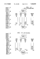
FIG. 9 depicts the state of the system at the end of the batch arrival. Pointers 501, 502, 503, 504, 505 and 506 depict for the relevant channels (i.e., i, j, k and m), the values of the receive pointer, epoch counter, overflow counter, priority register, epoch register and transmit pointer, respectively. Items 507, 508 and 509 depict the epoch queues #0, #1 and #2, (i.e., 507, 508 and 509) respectively with the packets stored in them. Overflow queue OC, 510, is shown with the packets stored in it.
The transmitter 512 had initiated the transmit pointer 506 to zero at startup, step 601. The transmitter then checks, at the beginning of service epoch (i.e., beginning of an outgoing slot), at 702 if the epoch queue pointed by the transmit pointer (i.e., EO#TP or EQ(O)) is empty. After the arrival of the above described batch, the transmitter 512 will find the system not empty. Consequently, at 703, the transmitter 512 serves the packet at the head of the line in epoch queue 507 pointed by the transmit pointer. Packet i1 is transferred to the outgoing time slot on facility 514, EC(i) is decremented to 2 and another test is performed, step 704, to check if the epoch queue pointed by the transmit pointer (i.e., EQ(TP)) is empty. The answer is no and, at step 703, the transmitter serves the packet at the head of the line in the epoch queue pointed by the transmit pointer, i.e., epoch queue # 0, 507. Packet j1 is transferred to the outgoing slot, EC(j) is decremented to 2 and another test is performed, at step 704, to check if the epoch queue pointed by the transmit pointer (i.e., EQ(TP)) is empty. The answer is no and, at step 703, the transmitter serves the packet at the head of the line in the epoch queue pointed by the transmit pointer, i.e., epoch queue # 0, 507. Packet k1 is transferred to the outgoing slot, EC(k) is decremented to 0 and another test is performed, at step 704, to check if the epoch queue pointed by the transmit pointer (i.e., EQ(TP)) is empty. The answer is no and, at step 703, the transmitter serves the packet at the head of the line in the epoch queue pointed by the transmit pointer, i.e., epoch queue # 0, 507. Packet m1 is transferred to the outgoing slot, EC(m) is decremented to 3 and another test is performed, at step 704 to check if the epoch queue pointed by the transmit pointer (i.e., EQ(TP)) is empty. The answer is no and, at step 703, the transmitter serves the packet at the head of the line in the epoch queue pointed by the transmit pointer, i.e., epoch queue # 0, 507. Packet m2 is transferred to the outgoing slot, EC(m) is decremented to 2 and another test is performed, at step 704, to check if the epoch queue pointed by the transmit pointer (i.e., EQ(TP)) is empty. The answer is yes and, in step 705, the transmitter increments the transmit pointer to TP=1, in step 706, and initiates the overflow queue sorter.
FIG. 10 depicts the state of the system at the end of the first cycle. At step 801, the overflow queue sorter 510 starts its operation. A test is performed, at step 802 to check if the overflow queue 510 is empty. The answer is no and, at step 803, the channel number of the head-of-the-line packet in the overflow queue (i.e., i) is read. A test is performed, at step 804, to check if EC(i)=0. Since there are two packets from channel i in the epoch queues the answer is no, and another test is performed, at step 810, to check if ER(i)<PR(i). Since one packet from channel i has been placed in the epoch queue pointed by RP(i), ER(i)=PR(i1; the answer is no and another test is performed, at step 811, to check if RP(i)=TP+2. Since RP(i)=2 and TP+2=3, the answer is no and step 809 is performed. RP(i) is incremented to three, ER(i) is assigned the value of one, packet i4 is placed in the epoch queue pointed by RP(i), which is epoch queue # 0, 507. At step 813 the value of EC(i) is incremented to 3 and the value of OC(i) is decremented to 3. Another test is performed at step 802 to check if the overflow queue, 510 is empty. The answer is no and, at step 803, the channel number of the head-of-the-line packet in the overflow queue (i.e., i) is read. A test is performed, at step 804, to check if EC(i)=0. Since there are three packets from channel i in the epoch queues the answer is no, and another test is performed, at step 810, to check if ER(i)<PR(i). Since one packet from channel i has been placed in the epoch queue pointed by RP(i), ER(i)=PR(i)=1; the answer is no and another test is performed, at step 811, to check if RP(i)=TP+2. Since RP(i)=3 and TP+2=3, the answer is yes and step 812 is performed and the overflow queue sorter quits.
FIG. 11 depicts the state of the system after the operation of the overflow queue sorter. The transmitter resumes operation, step 701, and checks, in step 702, at the beginning of service epoch (i.e., beginning of an outgoing slot), if the epoch queue pointed by the transmit pointer (i.e., EQ(TP)) is empty. Since epoch queue # 1, 508, is not empty the answer is no and, at step 703, the transmitter serves the packet at the head of the line. Packet i2 is transferred to the outgoing slot, EC(i) is decremented to 2 and another test is performed, at step 704, to check if the epoch queue pointed by the transmit pointer (i.e., EQ(TP)) is empty. The answer is no and, at step 703, the transmitter serves the packet at the head of the line in the epoch queue pointed by the transmit pointer, i.e., #1, 508. Packet j2 is transferred to the outgoing slot, EC(j) is decremented to 1 and another test is performed, at step 704, to check if the epoch queue pointed by the transmit pointer (i.e., EQ(TP)) is empty. The answer is no and, at step 703, the transmitter serves the packet at the head of the line in the epoch queue pointed by the transmit pointer, i.e., #1, step 508. Packet m3 is transferred to the outgoing slot, EC(m) is decremented to 1 and another test is performed, at step 704, to check if the epoch queue pointed by the transmit pointer (i.e., EQ(TP)) is empty. The answer is no and, at step 703, the transmitter serves the packet at the head of the line in the epoch queue pointed by the transmit pointer, i.e., #1, step 508. Packet m4 is transferred to the outgoing slot, EC(m) is decremented to 0 and another test is performed, at step 704, to check if the epoch queue pointed by the transmit pointer (i.e., EQ(TP)) is empty. The answer is yes, and the transmitter increments the transmit pointer to TP=2, at step 705, and initiates the overflow queue sorter at step 706.
FIG. 12 depicts the state of the system at the end of the second cycle. A test is performed, at step 802, to check if the overflow queue 510 is empty. The answer is no and, at step 803, the channel number of the head-of-the-line packet in the overflow queue (i.e., i) is read. A test is performed, at step 804, to check if EC(i)=0. Since there are two packets from channel i in the cycle queues the answer is no, and another test is performed, at step 810, to check if ER(i)<PR(i). Since one packet from channel i has been placed in the epoch queue pointed by RP(i), ER(i)=PR(i)=1; the answer is no and another test is performed, at step 811, to check if RP(i)=TP+2. Since RP(i)=3 and TP+2=4, the answer is no and step 809 is performed. RP(i) is incremented to four, ER(i) is assigned the value of one, packet i5 is placed in the cycle queue pointed by RP(i), which is cycle queue # 1, 508. At step 813, the value of EC(i) is incremented to 3 and the value of OC(i) is decremented to 2. Another test is performed, at step 802, to check if the overflow queue 510 is empty. The answer is no and, at step 803, the channel number of the head-of-the-line packet in the overflow queue (i.e., i) is read. A test is performed, at step 804, to check if EC(i)=0. Since there are three packets from channel i in the epoch queues the answer is no, and another test is performed, at step 810, to check if ER(i)<PR(i). Since one packet from channel i has been placed in the epoch queue pointed by RP(i), ER(i)=PR(i)=1; the answer is no and another test is performed, at step 811, to check if RP(i)=TP+2. Since RP(i)=4 and TP+2=4, the answer is yes and step 812 is performed and the overflow queue sorter quits.
FIG. 13 depicts the state of the system after the operation of the overflow queue sorter. The transmitter resumes operation and checks, at the beginning of service epoch (i.e., beginning of an outgoing slot), at step 702, if the epoch queue pointed by the transmit pointer (i.e., EQ(TP)) is empty. Since epoch queue # 0, 507, is not empty the answer is no and, at step 703, the transmitter serves the packet at the head of the line. Packet i3 is transferred to the outgoing slot, EC(i) is decremented to 2 and another test is performed, at step 704, to check if the epoch queue pointed by the transmit pointer (i.e., EQ(TP)) is empty. The answer is no and, at step 703, the transmitter serves the packet at the head of the line. Packet j3 is transferred to the outgoing slot, EC(j) is decremented to 0 and another test is performed, at step 704, to check if the epoch queue pointed by the transmit pointer (i.e., EQ(TP)) is empty. The answer is yes, and the transmitter increments the transmit pointer to TP=3, at step 705, and initiates the overflow queue sorter at step 706.
FIG. 14 depicts the state of the system at the end of the third cycle. A test is performed, at step 802, to check if the overflow queue 510, is empty. The answer is no and, at step 803, the channel number of the head-of-the-line packet in the overflow queue (i.e., i) is read. A test is performed, at step 804 to check if EC(i)=0. Since there are two packets from channel i in the epoch queues the answer is no, and another test is performed, at step 810, to check if ER(i)<PR(i). Since one packet from channel i has been placed in the epoch queue pointed by RP(i), ER(i)=PR(i)=1; the answer is no and another test is performed, at step 811, to check if RP(i)=TP+2. Since RP(i)=4 and TP+2=5, the answer is no and step 809 is performed. RP(i) is incremented to five, ER(i) is assigned the value of one, packet i6 is placed in the epoch queue pointed by RP(i), which is epoch queue # 2, 509. At step 813, the value of EC(i) is incremented to 3 and the value of OC(i) is decremented to 1. Another test is performed, at step 802, to check if the overflow queue 510 is empty. The answer is no and, at step 803, the channel number of the head-of-the-line packet in the overflow queue (i.e., i) is read. A test is performed, at step 804, to check if EC(i)=0. Since there are three packets from channel i in the epoch queues the answer is no, and another test is performed, at step 810, to check if ER(i)<PR(i). Since one packet from channel i has been placed in the epoch queue pointed by RP(i), ER(i)=PR(i)=1; the answer is no and another test is performed, at step 811, to check if RP(i)=TP+2. Since RP(i)=5, the answer is yes and step 812 is performed and the overflow queue sorter quits.
We next assume that a single packet from channel j, j5, arrives to the receiver, at step 601, and finds the system in the state as depicted in FIG. 15. A test is performed, at step 602, to check if OC(j)=0. Since there is one packet from channel j in the overflow queue, the answer is no and step 603 is performed; packet j5 is placed in the overflow queue 510 and the value of OC(j) is incremented to 2.
FIG. 16 depicts the state of the system after the operation of the overflow queue sorter 510 and a single packet arrival. The transmitter 512 resumes operation and checks, at the beginning of service epoch (i.e., beginning of an outgoing slot), at step 702, if the epoch queue pointed by the transmit pointer (i.e., EQ(TP)) is empty. Since epoch queue # 0, 507 is not empty the answer is no and, at step 703, the transmitter 512 serves the packet at the head of the line. Packet i4 is transferred to the outgoing slot, EC(i) is decremented to 2 and another test is performed, at step 704, to check if the epoch queue pointed by the transmit pointer (i.e., EQ(TP)) 506 is empty. The answer is yes, and the transmitter increments the transmit pointer to TP=4, at step 705, and initiates the overflow queue sorter, at step 506.
FIG. 17 depicts the state of the system at the end of the fourth cycle. A test is performed, at step 802, to check if the overflow queue 510 is empty. The answer is no and, at step 803, the channel number of the head-of-the-line packet in the overflow queue (i.e., i) is read. A test is performed, at step 804, to check if EC(i)=0. Since there are two packets from channel i in the epoch queues the answer is no, and another test is performed, at step 810, to check if ER(i)<PR(i). Since one packet from channel i has been placed in the epoch queue pointed by RP(i), ER(i)=PR(i)=1; the answer is no and another test is performed, at step 811, to check if RP(i)=TP+2. Since RP(i)=5 and TP+2=6, the answer is no and step 809 is performed. RP(i) is incremented to five, ER(i) is assigned the value of one, packet i7 is placed in the epoch queue pointed by RP(i), which is epoch queue # 0, 507. At step 813, the value of EC(i) is incremented to 3 and the value of OC(i) is decremented to 0. Another test is performed, at step 802, to check if the overflow queue 510 is empty. The answer is no and, at step 803, the channel number of the head-of-the-line packet in the overflow queue (i.e., j) is read. A test is performed, at step 804 to check if EC(j)=0. Since there are no packets from channel j in the epoch queues the answer is yes, and another test is performed, at step 805, to check if RP(j)=TP. Since RP(j)=2 and TP=4, the answer is no and step 806 is performed; RP(j) is set to 4, ER(j) is set to 1 and the packet j4 is placed in the epoch queue pointed by RP(j). At step 813, OC(j) is decremented to 1 and EC(j) is incremented to 1. Another test is performed, at step 802, to check if the overflow queue 510 is empty. The answer is no and, at step 803, the channel number of the head-of-the-line packet in the overflow queue 510 (i.e., j) is read. A test is performed, at step 804, to check if EC(j)=0. Since there is one packet from channel j in the epoch queues the answer is no, and another test is performed, at step 810, to check if ER(j)<PR(j). Since one packet from channel j has been placed in the epoch queue pointed by RP(j), ER(j)=PR(j)=1; the answer is no and another test is performed, at step 811, to check if RP(j)=TP+2. Since RP(j)=4 and TP+2=6, the answer is no and step 809 is performed. RP(j) is incremented to five, ER(j) is assigned the value of one, packet j5 is placed in the epoch queue pointed by RP(j), which is epoch queue # 2, 509. At step 813, the value of EC(j) is incremented to 2 and the value of OC(j) is decremented to 0. A test is performed, at step 802, to check if the overflow queue 510 is empty. The answer is yes and, at step 812, the overflow queue sorter quits.
FIG. 18 depicts the state of the system after the operation of the overflow queue sorter 510. The transmitter 512 resumes operation and checks, at the beginning of service epoch (i.e., beginning of an outgoing slot), at step 702, if the epoch queue pointed by the transmit pointer 506 (i.e., EQ(TP)) is empty. Since epoch queue # 1, 508 is not empty the answer is no and, at step 703, the transmitter 512 serves the packet at the head of the line. Packet i5 is transferred to the outgoing slot, EC(i) is decremented to 2 and another test is performed, at step 704, to check if the epoch queue pointed by the transmit pointer 506 (i.e., EQ(TP)) is empty. The answer is no and, at step 703, the transmitter serves the packet at the head of the line. Packet j4 is transferred to the outgoing slot, EC(j) is decremented to 1 and another test is performed, at step 704, to check if the epoch queue pointed by the transmit pointer 506 (i.e., EQ(TP)) is empty. The answer is yes, and the transmitter increments the transmit pointer to TP=5 at step 705 and initiates the overflow queue sorter at step 706.
FIG. 19 depicts the state of the system at the end of the fifth cycle. A test is performed, at step 802, to check if the overflow queue 510 is empty. The answer is yes and, at step 812, the overflow queue sorter quits. The transmitter resumes operation and checks, at the beginning of service epoch (i.e., beginning of an outgoing slot), step 702, if the epoch queue pointed by the transmit pointer (i.e., EQ(TP)) is empty. Since epoch queue # 2, 509 is not empty the answer is no and, at step 703, the transmitter 512 serves the packet at the head of the line. Packet i6 is transferred to the outgoing slot, EC(i) is decremented to 1 and another test is performed, at step 704, to check if the epoch queue pointed by the transmit pointer 506 (i.e., EQ(TP)) is empty. The answer is no and, at step 703, the transmitter 512 serves the packet at the head of the line. Packet j5 is transferred to the outgoing slot, EC(j) is decremented to 0 and another test is performed, at step 704, to check if the epoch queue pointed by the transmit pointer (i.e., EQ(TP)) is empty. The answer is yes, and the transmitter increments the transmit pointer 506 to TP=6 at step 705 and initiates the overflow queue sorter at step 706.
FIG. 20 depicts the state of the system at the end of the sixth cycle. A test is performed, at step 802, to check if the overflow queue 510 is empty. The answer is yes and, at step 812, the overflow queue sorter quits. The transmitter 512 resumes operation and checks, at the beginning of service epoch (i.e., beginning of an outgoing slot), at step 702, if the epoch queue pointed by the transmit pointer 506 (i.e., EQ(TP)) is empty. Since epoch queue # 0, 507 is not empty the answer is no and, at step 703, the transmitter 512 serves the packet at the head of the line. Packet i7 is transferred to the outgoing slot, EC(i) is decremented to 0 and another test is performed, at step 704, to check if the epoch queue pointed by the transmit pointer 506 (i.e., EQ(TP)) is empty. The answer is yes , and the transmitter increments the transmit pointer to TP=7 at step 705 and initiates the overflow queue sorter at step 706.
Finally, the system becomes empty. The overflow queue sorter, at step 802, finds the overflow queue 510 empty and quits at step 812. The transmitter resumes operation, at step 702, and repeats this check until arrivals occur.
Thus, the order of departures after the packets joined the system was: i1, j1, k1, m1, m2, (in the first epoch); i2, j2, m3, m4, (in the second epoch); i3, j3, (in the third epoch); i4, (in the fourth epoch); i5, j4, (in the fifth epoch); i6, j5, (in the sixth epoch); i7, (in the seventh epoch). The order of departures without the distortions caused by the overflow queue would be: i1, j1, k1, m1, m2, (in the first epoch); i2, j2, m3, m4, (in the second epoch); i3, j3, (in the third epoch); i4, j4, (in the fourth epoch); i5, j5, (in the fifth epoch); i6, (in the sixth epoch); i7, (in the seventh epoch). Notice that packets j4 and j5 missed an epoch. Batches longer than the number of epoch queues could have some of their packets missing epoch. This effect may or may not be beneficial. The choice of the number of epoch queues, 507-509, as well as their sizes should be driven by engineering and performance guidelines.
The invention can be applied for serving packets at trunks in a slotted packet data network. It can also be applied in other environments that need effective scheduling processes such as in a multi-task/multi-user computer system. In the case of a slotted packet data network, it requires each packet to carry a channel identifier or some information that can be mapped into a channel identifier. In case of a computer system, it requires each process to have an identification number.
Thus, what has been described is merely illustrative of the application of the principles of the present invention. Other arrangements and methods can be implemented by those skilled in the art without departing from the spirit and scope of the present invention. It should be noted that the choice of the number of epoch queues as well as the sizes of the epoch queues and overflow queue should be selected based on engineering and performance requirements.

Claims (29)

We claim:
1. Circuit apparatus for interfacing a received multichannel data signal to a communication facility, said data signal including a number of data batches, each data batch having been received over one of the multiple data channels and each data batch including one or more data packets, said apparatus comprising
a sorter means for sorting information identifying one or more data packets of each data batch, into one or more of a plurality of N epoch queues such that for each data batch no information identifying more than a predetermined number P of data packets from a particular channel is inputted into each epoch queue and
a memory server means for cyclically serving each epoch queue exhaustively to said facility.
2. The apparatus of claim 1 further comprising
a memory unit including said N epoch queues.
3. The apparatus of claim 1 wherein
said sorter means sorts said information into an overflow queue after each epoch queue is saturated, such that all epoch queues are full or each epoch queue contains information identifying no more than P data packets from a particular channel, and wherein said sorter means subsequently sorts said information contents of said overflow queue sequentially into one or more epoch queues such that no information identifying more than P data packets from a particular data channel is inputted into one or more epoch queues.
4. The apparatus of claim 3 wherein said sorter means sorts said information of said overflow queue into at least a first epoch queue after said first epoch queue has been served by said server means and before another epoch queue has been served by said server means.
5. The apparatus of claim 3 including an overflow counter (OC) for counting for each channel the number of data packets stored in said overflow queue.
6. The apparatus of claim 3 wherein when said sorter means determines that a selected epoch queue being served is full, said sorter means stores information, identifying one or more data packets of a data batch, into another epoch queue or into the overflow queue, said information being that which otherwise would have been stored in the full epoch queue.
7. The apparatus of claim 6 wherein when said sorter means determines that a memory embodying said N epoch queues and said overflow queue, has reached a predetermined occupancy threshold, said sorter means discards each data packet associated with a new message of said received data signal.
8. The apparatus of claim 1 wherein said information identifying one or more data packets of each data batch is the one or more data packets themselves.
9. The apparatus of claim 1 wherein the information identifying one or more data packets of each data batch is a pointer identifying where the one or more data packets themselves are stored.
10. The apparatus of claim 1 wherein when said sorter means determines that a selected epoch queue being served is full, said sorter means stores information, identifying one or more data packets of said received data, into another epoch queue, said information being that which otherwise would have been stored in the full epoch queue.
11. The apparatus of claim 10 wherein when said sorter means determines that a memory, embodying said N cycle queues, has reached a predetermined occupancy threshold, said sorter means discards packets which are part of a new message of said received data signal.
12. The apparatus of claim 1 wherein said sorter means includes
a first sorter means for sorting said received data signal and
a second sorter means for sorting the contents of said overflow queue.
13. The apparatus of claim 12 wherein said second sorter means is given priority over said first sorter means to sort information into a epoch queue that has just been served by said server means.
14. The apparatus of claim 1 wherein once said sorter means has sorted information from a particular channel into said overflow queue, no subsequent information from said particular channel is stored in one of said N epoch queues until said overflow queue has been emptied of information from said particular channel.
15. The apparatus of claim 1 wherein the number P can be independently specified for each of said channels.
16. The apparatus of claim 1 wherein P is equal to one.
17. The apparatus of claim 1 including a epoch counter (EC) for counting for each channel the number of data packets stored in all N epoch queues.
18. The apparatus of claim 1 including a receive pointer (RP) for specifying for each channel the epoch queue in which information should be stored.
19. The apparatus of claim 18 including an epoch register (ER) for counting the number of data packets of each channel the number of packets stored in the epoch queue that is presently being pointed to by the receive pointer (RP).
20. The apparatus of claim 1 including a transmit pointer (TP) for indicating the epoch queue that is currently being served by said memory server means.
21. The apparatus of claim 1 including a receive pointer (RP) for specifying for each channel the epoch queue in which information should be stored, said receiver pointer being incremented each time said sorter means sorts to another epoch queue;
a transmit pointer (TP) for indicating the epoch queue that is currently being served by said memory server means, said transmit pointer being incremented each time said memory server means serves another epoch queue; and
wherein said receive pointer and said transmit pointer each reset when they reach the count M, where M is an integer multiple of N.
22. The apparatus of claim 1 including a priority register (PR) for specifying for each channel the number P of data packets that should be sorted into each epoch queue, wherein the higher the number P for a channel the higher the data transmission rate for that channel relative to other channels.
23. A method of interfacing a received multichannel data signal to a communication facility, said data signal including a number of data batches, each data batch having been received over one of the multiple data channels and each data batch including one or more data packets, said method comprising the steps of
sorting information identifying one or more data packets of each data batch into one or more of a plurality of epoch queues such that for each data batch no information identifying more than a predetermined number of P data packets from a particular channel is inputted into each epoch queue, and
cyclically serving each epoch queue exhaustively to said facility.
24. The method of claim 23 wherein said sorting step further sorts said information into an overflow queue after each epoch queue is saturated, such that all epoch queues are full or each epoch queue contains information identifying no more than P data packets from a particular channel, and wherein said sorting step subsequently sorts said information contents of said overflow queue sequentially, such that no information identifying more than P data packets from a particular data channel is inputted into one or more epoch queues.
25. The method of claim 24 wherein said sorting step sorts said information of said overflow queue into at least a first epoch queue after said first epoch queue has been served during said serving step and before another epoch queue has been served during said serving step.
26. The method of claim 24 wherein said sorting step includes the step of
determining when a selected epoch queue being served is full, and
storing information identifying one or more data packets of a data batch into another epoch queue or into the overflow queue, said information being that which otherwise would have been stored in the full epoch queue.
27. The method of claim 26 wherein said determining step determines when said epoch queues and said overflow queue have reached a predetermined occupancy threshold, and wherein in response to said determination said apparatus discards each data packet associated with a new message of said received data signal.
28. The method of claim 23 wherein said sorting step includes the steps of
determining when a selected epoch queue being served is full, and
storing information, identifying one or more data packets of said received data, into another epoch queue, said information being that which otherwise would have been stored in the full epoch queue.
29. The method of claim 28 wherein said determining step determines when said N epoch queue has reached a predetermined occupancy threshold, it discards packets which are part of a new message of said received data signal.
US07/629,282 1990-12-17 1990-12-17 Data channel scheduling discipline arrangement and method Expired - Lifetime US5166930A (en)

Priority Applications (6)

Application Number Priority Date Filing Date Title
US07/629,282 US5166930A (en) 1990-12-17 1990-12-17 Data channel scheduling discipline arrangement and method
CA002054355A CA2054355C (en) 1990-12-17 1991-10-28 Data channel scheduling discipline arrangement and method
AU88303/91A AU632006B2 (en) 1990-12-17 1991-11-29 Data channel scheduling discipline arrangement and method
EP91311193A EP0491489B1 (en) 1990-12-17 1991-12-02 Data channel scheduling discipline arrangement and method
DE69131224T DE69131224T2 (en) 1990-12-17 1991-12-02 Time allocation method and device for data channel
JP3351198A JPH0720124B2 (en) 1990-12-17 1991-12-13 Data channel scheduling apparatus and method

Applications Claiming Priority (1)

Application Number Priority Date Filing Date Title
US07/629,282 US5166930A (en) 1990-12-17 1990-12-17 Data channel scheduling discipline arrangement and method

Publications (1)

Publication Number Publication Date
US5166930A true US5166930A (en) 1992-11-24

Family

ID=24522350

Family Applications (1)

Application Number Title Priority Date Filing Date
US07/629,282 Expired - Lifetime US5166930A (en) 1990-12-17 1990-12-17 Data channel scheduling discipline arrangement and method

Country Status (6)

Country Link
US (1) US5166930A (en)
EP (1) EP0491489B1 (en)
JP (1) JPH0720124B2 (en)
AU (1) AU632006B2 (en)
CA (1) CA2054355C (en)
DE (1) DE69131224T2 (en)

Cited By (94)

* Cited by examiner, † Cited by third party
Publication number Priority date Publication date Assignee Title
US5357516A (en) * 1992-03-25 1994-10-18 Motorola, Inc. Apparatus for use in time division multiplexed communication systems
US5390176A (en) * 1991-04-10 1995-02-14 U.S. Philips Corporation Low delay or low loss switch for ATM
WO1995008904A1 (en) * 1993-09-20 1995-03-30 Motorola, Inc. Device and method for cell processing in cell relay nodes
US5404354A (en) * 1992-11-06 1995-04-04 Roke Manor Research Limited ATM signal processors
US5535202A (en) * 1994-03-16 1996-07-09 Mitsubishi Denki Kabushiki Kaisha Priority processing of ATM cells using shift register stages
US5546594A (en) * 1991-11-26 1996-08-13 Kabushiki Kaisha Toshiba Cooperative distributed problem solver
US5586264A (en) * 1994-09-08 1996-12-17 Ibm Corporation Video optimized media streamer with cache management
US5598535A (en) * 1994-08-01 1997-01-28 International Business Machines Corporation System for selectively and cumulatively grouping packets from different sessions upon the absence of exception condition and sending the packets after preselected time conditions
US5625846A (en) * 1992-12-18 1997-04-29 Fujitsu Limited Transfer request queue control system using flags to indicate transfer request queue validity and whether to use round-robin system for dequeuing the corresponding queues
US5631934A (en) * 1994-09-16 1997-05-20 Telefonaktiebolaget Lm Ericsson Method for adapting data flows
WO1997020414A1 (en) * 1995-11-27 1997-06-05 Telefonaktiebolaget Lm Ericsson (Publ) Scheduler for an information packet switch
US5692156A (en) * 1995-07-28 1997-11-25 International Business Machines Corp. Computer program product for overflow queue processing
US5715474A (en) * 1992-04-30 1998-02-03 Motorola, Inc. Simultaneous control of radio frequency modem in a multi-tasking system using a single session manager program with separate command queue for each application program
US5732087A (en) * 1996-05-10 1998-03-24 Mitsubishi Electric Information Technology Center America, Inc. ATM local area network switch with dual queues
US5748614A (en) * 1995-06-09 1998-05-05 Siemens Aktiengesellschaft Method for scheduling message cells leaving an ATM node
US5764641A (en) * 1995-09-08 1998-06-09 Cisco Systems, Inc. Early and integrated tail packet discard system
WO1998027696A1 (en) * 1996-12-05 1998-06-25 3Com Corporation Method and apparatus for time-based download control
US5794073A (en) * 1994-11-07 1998-08-11 Digital Equipment Corporation Arbitration system for a shared DMA logic on a network adapter with a large number of competing priority requests having predicted latency field
US5793978A (en) * 1994-12-29 1998-08-11 Cisco Technology, Inc. System for routing packets by separating packets in to broadcast packets and non-broadcast packets and allocating a selected communication bandwidth to the broadcast packets
US5859853A (en) * 1996-06-21 1999-01-12 International Business Machines Corporation Adaptive packet training
US5867663A (en) * 1995-07-19 1999-02-02 Fujitsu Network Communications, Inc. Method and system for controlling network service parameters in a cell based communications network
US5867666A (en) * 1994-12-29 1999-02-02 Cisco Systems, Inc. Virtual interfaces with dynamic binding
US5870629A (en) * 1996-03-21 1999-02-09 Bay Networks, Inc. System for servicing plurality of queues responsive to queue service policy on a service sequence ordered to provide uniform and minimal queue interservice times
US5875175A (en) * 1997-05-01 1999-02-23 3Com Corporation Method and apparatus for time-based download control
US5893924A (en) * 1995-07-28 1999-04-13 International Business Machines Corporation System and method for overflow queue processing
US5901334A (en) * 1993-12-30 1999-05-04 International Business Machines Corporation System for calculating expected length of time in transient queue by a formula in the event items cannot be allocated to the buffer
US5901139A (en) * 1995-09-27 1999-05-04 Nec Corporation ATM cell buffer managing system in ATM node equipment
US6035105A (en) * 1996-01-02 2000-03-07 Cisco Technology, Inc. Multiple VLAN architecture system
US6078590A (en) * 1997-07-14 2000-06-20 Cisco Technology, Inc. Hierarchical routing knowledge for multicast packet routing
US6091725A (en) * 1995-12-29 2000-07-18 Cisco Systems, Inc. Method for traffic management, traffic prioritization, access control, and packet forwarding in a datagram computer network
US6097718A (en) * 1996-01-02 2000-08-01 Cisco Technology, Inc. Snapshot routing with route aging
US6101115A (en) * 1998-08-07 2000-08-08 Cisco Technology, Inc. CAM match line precharge
US6111877A (en) * 1997-12-31 2000-08-29 Cisco Technology, Inc. Load sharing across flows
US6122272A (en) * 1997-05-23 2000-09-19 Cisco Technology, Inc. Call size feedback on PNNI operation
US6157641A (en) * 1997-08-22 2000-12-05 Cisco Technology, Inc. Multiprotocol packet recognition and switching
US6160853A (en) * 1998-02-09 2000-12-12 At&T Corp Modem concentrator
US6178455B1 (en) 1997-01-17 2001-01-23 Scientific-Atlanta, Inc. Router which dynamically requests a set of logical network addresses and assigns addresses in the set to hosts connected to the router
US6182147B1 (en) 1998-07-31 2001-01-30 Cisco Technology, Inc. Multicast group routing using unidirectional links
US6182224B1 (en) 1995-09-29 2001-01-30 Cisco Systems, Inc. Enhanced network services using a subnetwork of communicating processors
US6212182B1 (en) 1996-06-27 2001-04-03 Cisco Technology, Inc. Combined unicast and multicast scheduling
US6212183B1 (en) 1997-08-22 2001-04-03 Cisco Technology, Inc. Multiple parallel packet routing lookup
US6230203B1 (en) 1995-10-20 2001-05-08 Scientific-Atlanta, Inc. System and method for providing statistics for flexible billing in a cable environment
US6243667B1 (en) 1996-05-28 2001-06-05 Cisco Systems, Inc. Network flow switching and flow data export
US6249819B1 (en) 1996-12-06 2001-06-19 Fujitsu Network Communications, Inc. Method for flow controlling ATM traffic
US6272150B1 (en) 1997-01-17 2001-08-07 Scientific-Atlanta, Inc. Cable modem map display for network management of a cable data delivery system
US6286058B1 (en) 1997-04-14 2001-09-04 Scientific-Atlanta, Inc. Apparatus and methods for automatically rerouting packets in the event of a link failure
US6298070B1 (en) 1998-05-07 2001-10-02 International Business Machines Corporation Packet training with an adjustable optimum number of packets
US6304546B1 (en) 1996-12-19 2001-10-16 Cisco Technology, Inc. End-to-end bidirectional keep-alive using virtual circuits
US6308219B1 (en) 1998-07-31 2001-10-23 Cisco Technology, Inc. Routing table lookup implemented using M-trie having nodes duplicated in multiple memory banks
US6330599B1 (en) 1997-08-05 2001-12-11 Cisco Technology, Inc. Virtual interfaces with dynamic binding
US6343072B1 (en) 1997-10-01 2002-01-29 Cisco Technology, Inc. Single-chip architecture for shared-memory router
US20020023168A1 (en) * 2000-04-13 2002-02-21 International Business Machines Corporation Method and system for network processor scheduling based on service levels
US6356530B1 (en) 1997-05-23 2002-03-12 Cisco Technology, Inc. Next hop selection in ATM networks
US6370121B1 (en) 1998-06-29 2002-04-09 Cisco Technology, Inc. Method and system for shortcut trunking of LAN bridges
US6377577B1 (en) 1998-06-30 2002-04-23 Cisco Technology, Inc. Access control list processing in hardware
US6389506B1 (en) 1998-08-07 2002-05-14 Cisco Technology, Inc. Block mask ternary cam
US6401147B1 (en) * 1999-05-24 2002-06-04 Advanced Micro Devices, Inc. Split-queue architecture with a first queue area and a second queue area and queue overflow area having a trickle mode and an overflow mode based on prescribed threshold values
US6434120B1 (en) 1998-08-25 2002-08-13 Cisco Technology, Inc. Autosensing LMI protocols in frame relay networks
US20020116435A1 (en) * 2001-02-22 2002-08-22 International Business Machines Corporation Performance of channels used in communicating between senders and receivers
US20020126673A1 (en) * 2001-01-12 2002-09-12 Nirav Dagli Shared memory
US6467091B1 (en) 1995-10-20 2002-10-15 Scientific-Atlanta, Inc. Constant bit rate transport in a contention based medium access control
US6490298B1 (en) 1999-02-26 2002-12-03 Harmonic Inc. Apparatus and methods of multiplexing data to a communication channel
US20030014484A1 (en) * 2000-11-09 2003-01-16 Arnon Netzer Scheduling in a remote-access server
US6512766B2 (en) 1997-08-22 2003-01-28 Cisco Systems, Inc. Enhanced internet packet routing lookup
US6594263B1 (en) * 1995-07-06 2003-07-15 Telefonaktiebolaget Lm Ericsson (Publ) ATM throttling
US6603772B1 (en) 1999-03-31 2003-08-05 Cisco Technology, Inc. Multicast routing with multicast virtual output queues and shortest queue first allocation
US20030185215A1 (en) * 2001-02-14 2003-10-02 Wright David A. Encapsulation method and apparatus for communicating fixed-length data packets through an intermediate network
US6735207B1 (en) 2000-06-13 2004-05-11 Cisco Technology, Inc. Apparatus and method for reducing queuing memory access cycles using a distributed queue structure
US6757791B1 (en) 1999-03-30 2004-06-29 Cisco Technology, Inc. Method and apparatus for reordering packet data units in storage queues for reading and writing memory
US6760331B1 (en) 1999-03-31 2004-07-06 Cisco Technology, Inc. Multicast routing with nearest queue first allocation and dynamic and static vector quantization
US6771642B1 (en) 1999-01-08 2004-08-03 Cisco Technology, Inc. Method and apparatus for scheduling packets in a packet switch
US20040194087A1 (en) * 2002-04-11 2004-09-30 International Business Machines Corporation Batch processing of requests in a data processing network
US6831923B1 (en) 1995-08-04 2004-12-14 Cisco Technology, Inc. Pipelined multiple issue packet switch
US6853638B2 (en) 1998-04-01 2005-02-08 Cisco Technology, Inc. Route/service processor scalability via flow-based distribution of traffic
US6889181B2 (en) 1996-05-28 2005-05-03 Cisco Technology, Inc. Network flow switching and flow data export
US6917966B1 (en) 1995-09-29 2005-07-12 Cisco Technology, Inc. Enhanced network services using a subnetwork of communicating processors
US6920112B1 (en) 1998-06-29 2005-07-19 Cisco Technology, Inc. Sampling packets for network monitoring
US20050195826A1 (en) * 2004-03-08 2005-09-08 Surf Communication Solutions Ltd. Multi-parameter scheduling in communication systems
US6975638B1 (en) * 2000-10-13 2005-12-13 Force10 Networks, Inc. Interleaved weighted fair queuing mechanism and system
US6978311B1 (en) * 2000-02-09 2005-12-20 Surf Communications Solutions, Ltd. Scheduling in a remote-access server
US6983327B2 (en) 1996-04-03 2006-01-03 Scientific-Atlanta, Inc. System and method for providing statistics for flexible billing in a cable environment
US7065762B1 (en) 1999-03-22 2006-06-20 Cisco Technology, Inc. Method, apparatus and computer program product for borrowed-virtual-time scheduling
US7116669B1 (en) 1997-06-17 2006-10-03 Cisco Technology, Inc. Format for automatic generation of unique ATM addresses used for PNNI
US7154902B1 (en) * 2002-10-21 2006-12-26 Force10 Networks, Inc. Epoch-based packet switching
US7200168B1 (en) 1997-11-13 2007-04-03 Surf Communication Solutions Ltd. Stable operation of media gateway
US7246148B1 (en) 1995-09-29 2007-07-17 Cisco Technology, Inc. Enhanced network services using a subnetwork of communicating processors
US20070244814A1 (en) * 2000-11-13 2007-10-18 Fairfield Resources International, Inc. Communication Terminal Device and Billing Device
US7286525B1 (en) 1997-12-31 2007-10-23 Cisco Technology, Inc. Synchronous pipelined switch using serial transmission
US20080084898A1 (en) * 2004-10-14 2008-04-10 Tokyo Denki University Exchange node and exchange node control method
US7570583B2 (en) 1997-12-05 2009-08-04 Cisco Technology, Inc. Extending SONET/SDH automatic protection switching
US20110179379A1 (en) * 1998-06-29 2011-07-21 At&T Labs, Inc. Emergency facility information system and methods
US20130054864A1 (en) * 2011-08-31 2013-02-28 William Hughes Buffer management using freelist buffers
US20140310369A1 (en) * 2011-12-23 2014-10-16 Vadim Makhervaks Shared send queue
US10481801B1 (en) * 2018-02-22 2019-11-19 Veritas Technologies Llc Optimizing storage quality of service (SQOS) by dynamically determining and managing optimal queue depth and system capacity

Families Citing this family (10)

* Cited by examiner, † Cited by third party
Publication number Priority date Publication date Assignee Title
MY121893A (en) * 1995-04-28 2006-03-31 Qualcomm Inc Method and apparatus for providing variable rate data in a communications system using statistical multiplexing.
EP1457895A3 (en) * 1995-10-26 2005-04-20 Matsushita Electric Industrial Co., Ltd. File System
JP3213697B2 (en) * 1997-01-14 2001-10-02 株式会社ディジタル・ビジョン・ラボラトリーズ Relay node system and relay control method in the relay node system
US6487212B1 (en) * 1997-02-14 2002-11-26 Advanced Micro Devices, Inc. Queuing structure and method for prioritization of frames in a network switch
IL132888A0 (en) 1999-11-11 2001-03-19 Surf Comm Solutions Ltd Channel load balancing
US7257642B1 (en) 1999-11-11 2007-08-14 Surp Communication Solutions Ltd. Channel load balancing
US7490328B2 (en) 2000-05-09 2009-02-10 Surf Communication Solutions, Ltd. Method and apparatus for allocating processor pool resources for handling mobile data connections
GB2379586A (en) * 2001-09-06 2003-03-12 Zarlink Semiconductor Ltd Processing requests for service using FIFO queues
US20040109463A1 (en) * 2002-12-05 2004-06-10 Alcatel Canada Inc. Efficient data transmission method
US9906460B2 (en) 2015-12-31 2018-02-27 Alcatel-Lucent Usa Inc. Data plane for processing function scalability

Citations (8)

* Cited by examiner, † Cited by third party
Publication number Priority date Publication date Assignee Title
WO1986002510A1 (en) * 1984-10-18 1986-04-24 Hughes Aircraft Company PACKET SWITCHED MULTIPLE QUEUE NxM SWITCH NODE AND PROCESSING METHOD
US4644533A (en) * 1985-05-06 1987-02-17 American Telephone & Telegraph Company Packet switch trunk circuit queueing arrangement
AU7473787A (en) * 1986-06-27 1988-01-07 Fujitsu Limited Packet data communication system with ring type transmission line
EP0323835A2 (en) * 1988-01-06 1989-07-12 Nec Corporation Packet concentrator and switch including a controller for assigning priorities to space switch input terminals for control of buffers
US4899334A (en) * 1987-10-19 1990-02-06 Oki Electric Industry Co., Ltd. Self-routing multistage switching network for fast packet switching system
US4899335A (en) * 1988-12-21 1990-02-06 American Telephone And Telegraph Company, At&T Bell Laboratories Self routing packet switching network architecture
US5016248A (en) * 1988-10-27 1991-05-14 Kabushiki Kaisha Toshiba Buffer memory device for packet data and method of controlling the device
US5021947A (en) * 1986-03-31 1991-06-04 Hughes Aircraft Company Data-flow multiprocessor architecture with three dimensional multistage interconnection network for efficient signal and data processing

Family Cites Families (1)

* Cited by examiner, † Cited by third party
Publication number Priority date Publication date Assignee Title
US4499576A (en) * 1982-08-13 1985-02-12 At&T Bell Laboratories Multiplexed first-in, first-out queues

Patent Citations (8)

* Cited by examiner, † Cited by third party
Publication number Priority date Publication date Assignee Title
WO1986002510A1 (en) * 1984-10-18 1986-04-24 Hughes Aircraft Company PACKET SWITCHED MULTIPLE QUEUE NxM SWITCH NODE AND PROCESSING METHOD
US4644533A (en) * 1985-05-06 1987-02-17 American Telephone & Telegraph Company Packet switch trunk circuit queueing arrangement
US5021947A (en) * 1986-03-31 1991-06-04 Hughes Aircraft Company Data-flow multiprocessor architecture with three dimensional multistage interconnection network for efficient signal and data processing
AU7473787A (en) * 1986-06-27 1988-01-07 Fujitsu Limited Packet data communication system with ring type transmission line
US4899334A (en) * 1987-10-19 1990-02-06 Oki Electric Industry Co., Ltd. Self-routing multistage switching network for fast packet switching system
EP0323835A2 (en) * 1988-01-06 1989-07-12 Nec Corporation Packet concentrator and switch including a controller for assigning priorities to space switch input terminals for control of buffers
US5016248A (en) * 1988-10-27 1991-05-14 Kabushiki Kaisha Toshiba Buffer memory device for packet data and method of controlling the device
US4899335A (en) * 1988-12-21 1990-02-06 American Telephone And Telegraph Company, At&T Bell Laboratories Self routing packet switching network architecture

Cited By (134)

* Cited by examiner, † Cited by third party
Publication number Priority date Publication date Assignee Title
US5390176A (en) * 1991-04-10 1995-02-14 U.S. Philips Corporation Low delay or low loss switch for ATM
US5546594A (en) * 1991-11-26 1996-08-13 Kabushiki Kaisha Toshiba Cooperative distributed problem solver
US5357516A (en) * 1992-03-25 1994-10-18 Motorola, Inc. Apparatus for use in time division multiplexed communication systems
US5715474A (en) * 1992-04-30 1998-02-03 Motorola, Inc. Simultaneous control of radio frequency modem in a multi-tasking system using a single session manager program with separate command queue for each application program
US5404354A (en) * 1992-11-06 1995-04-04 Roke Manor Research Limited ATM signal processors
US5625846A (en) * 1992-12-18 1997-04-29 Fujitsu Limited Transfer request queue control system using flags to indicate transfer request queue validity and whether to use round-robin system for dequeuing the corresponding queues
WO1995008904A1 (en) * 1993-09-20 1995-03-30 Motorola, Inc. Device and method for cell processing in cell relay nodes
US5408472A (en) * 1993-09-20 1995-04-18 Motorola, Inc. Device and method for cell processing in cell relay nodes
US5901334A (en) * 1993-12-30 1999-05-04 International Business Machines Corporation System for calculating expected length of time in transient queue by a formula in the event items cannot be allocated to the buffer
US5535202A (en) * 1994-03-16 1996-07-09 Mitsubishi Denki Kabushiki Kaisha Priority processing of ATM cells using shift register stages
US5598535A (en) * 1994-08-01 1997-01-28 International Business Machines Corporation System for selectively and cumulatively grouping packets from different sessions upon the absence of exception condition and sending the packets after preselected time conditions
US5754768A (en) * 1994-08-01 1998-05-19 International Business Machines Corporation System for selectively and cumulatively grouping packets from different sessions upon the absence of exception condition and sending the packets after preselected time conditions
US5586264A (en) * 1994-09-08 1996-12-17 Ibm Corporation Video optimized media streamer with cache management
US5631934A (en) * 1994-09-16 1997-05-20 Telefonaktiebolaget Lm Ericsson Method for adapting data flows
US6199124B1 (en) 1994-11-07 2001-03-06 Compaq Computer Corporation Arbitration system based on requester class and relative priority including transmit descriptor valid bit for a shared resource having multiple requesters
US5794073A (en) * 1994-11-07 1998-08-11 Digital Equipment Corporation Arbitration system for a shared DMA logic on a network adapter with a large number of competing priority requests having predicted latency field
US5881313A (en) * 1994-11-07 1999-03-09 Digital Equipment Corporation Arbitration system based on requester class and relative priority including transmit descriptor valid bit for a shared resource having multiple requesters
US5793978A (en) * 1994-12-29 1998-08-11 Cisco Technology, Inc. System for routing packets by separating packets in to broadcast packets and non-broadcast packets and allocating a selected communication bandwidth to the broadcast packets
US5867666A (en) * 1994-12-29 1999-02-02 Cisco Systems, Inc. Virtual interfaces with dynamic binding
US5748614A (en) * 1995-06-09 1998-05-05 Siemens Aktiengesellschaft Method for scheduling message cells leaving an ATM node
US6594263B1 (en) * 1995-07-06 2003-07-15 Telefonaktiebolaget Lm Ericsson (Publ) ATM throttling
US5867663A (en) * 1995-07-19 1999-02-02 Fujitsu Network Communications, Inc. Method and system for controlling network service parameters in a cell based communications network
US5692156A (en) * 1995-07-28 1997-11-25 International Business Machines Corp. Computer program product for overflow queue processing
US5893924A (en) * 1995-07-28 1999-04-13 International Business Machines Corporation System and method for overflow queue processing
US6327251B1 (en) 1995-08-03 2001-12-04 Cisco Technology, Inc. Snapshot routing
US6831923B1 (en) 1995-08-04 2004-12-14 Cisco Technology, Inc. Pipelined multiple issue packet switch
US5764641A (en) * 1995-09-08 1998-06-09 Cisco Systems, Inc. Early and integrated tail packet discard system
US5901139A (en) * 1995-09-27 1999-05-04 Nec Corporation ATM cell buffer managing system in ATM node equipment
US7246148B1 (en) 1995-09-29 2007-07-17 Cisco Technology, Inc. Enhanced network services using a subnetwork of communicating processors
US6917966B1 (en) 1995-09-29 2005-07-12 Cisco Technology, Inc. Enhanced network services using a subnetwork of communicating processors
US6182224B1 (en) 1995-09-29 2001-01-30 Cisco Systems, Inc. Enhanced network services using a subnetwork of communicating processors
US6640243B1 (en) 1995-09-29 2003-10-28 Cisco Technology, Inc. Enhanced network services using a subnetwork of communicating processors
US6467091B1 (en) 1995-10-20 2002-10-15 Scientific-Atlanta, Inc. Constant bit rate transport in a contention based medium access control
US6230203B1 (en) 1995-10-20 2001-05-08 Scientific-Atlanta, Inc. System and method for providing statistics for flexible billing in a cable environment
USRE44211E1 (en) 1995-10-20 2013-05-07 Scientific-Atlanta, Llc Constant bit rate transport in a contention based medium access control
US6295295B1 (en) 1995-11-27 2001-09-25 Telefonaktiebolaget Lm Ericsson Scheduler for an information packet switch
WO1997020414A1 (en) * 1995-11-27 1997-06-05 Telefonaktiebolaget Lm Ericsson (Publ) Scheduler for an information packet switch
US6091725A (en) * 1995-12-29 2000-07-18 Cisco Systems, Inc. Method for traffic management, traffic prioritization, access control, and packet forwarding in a datagram computer network
US7443858B1 (en) 1995-12-29 2008-10-28 Cisco Technology, Inc. Method for traffic management, traffic prioritization, access control, and packet forwarding in a datagram computer network
US6798776B1 (en) 1995-12-29 2004-09-28 Cisco Technology, Inc. Method for traffic management, traffic prioritization, access control, and packet forwarding in a datagram computer network
US8401027B2 (en) 1995-12-29 2013-03-19 Cisco Technology, Inc. Method for traffic management, traffic prioritization, access control, and packet forwarding in a datagram computer network
US6219699B1 (en) 1996-01-02 2001-04-17 Cisco Technologies, Inc. Multiple VLAN Architecture system
US6035105A (en) * 1996-01-02 2000-03-07 Cisco Technology, Inc. Multiple VLAN architecture system
US6097718A (en) * 1996-01-02 2000-08-01 Cisco Technology, Inc. Snapshot routing with route aging
US5870629A (en) * 1996-03-21 1999-02-09 Bay Networks, Inc. System for servicing plurality of queues responsive to queue service policy on a service sequence ordered to provide uniform and minimal queue interservice times
US6983327B2 (en) 1996-04-03 2006-01-03 Scientific-Atlanta, Inc. System and method for providing statistics for flexible billing in a cable environment
US5732087A (en) * 1996-05-10 1998-03-24 Mitsubishi Electric Information Technology Center America, Inc. ATM local area network switch with dual queues
US6243667B1 (en) 1996-05-28 2001-06-05 Cisco Systems, Inc. Network flow switching and flow data export
US6889181B2 (en) 1996-05-28 2005-05-03 Cisco Technology, Inc. Network flow switching and flow data export
US7475156B2 (en) 1996-05-28 2009-01-06 Cisco Technology, Inc. Network flow switching and flow data export
US7260518B2 (en) 1996-05-28 2007-08-21 Cisco Technology, Inc. Network flow switching and flow data report
US5859853A (en) * 1996-06-21 1999-01-12 International Business Machines Corporation Adaptive packet training
US6212182B1 (en) 1996-06-27 2001-04-03 Cisco Technology, Inc. Combined unicast and multicast scheduling
US7103007B2 (en) 1996-06-28 2006-09-05 Cisco Technology, Inc. Autosensing LMI protocols in frame relay networks
WO1998027696A1 (en) * 1996-12-05 1998-06-25 3Com Corporation Method and apparatus for time-based download control
US6249819B1 (en) 1996-12-06 2001-06-19 Fujitsu Network Communications, Inc. Method for flow controlling ATM traffic
US6538988B1 (en) 1996-12-19 2003-03-25 Cisco Technology, Inc. End-to-end bidirectional keep-alive using virtual circuits
US6304546B1 (en) 1996-12-19 2001-10-16 Cisco Technology, Inc. End-to-end bidirectional keep-alive using virtual circuits
US6519224B2 (en) 1997-01-17 2003-02-11 Scientific-Atlanta, Inc. Method of using routing protocols to reroute packets during a link failure
US6324267B1 (en) 1997-01-17 2001-11-27 Scientific-Atlanta, Inc. Two-tiered authorization and authentication for a cable data delivery system
US8522265B2 (en) 1997-01-17 2013-08-27 Scott E. Hrastar Modem apparatus for a cable data delivery system
US6208656B1 (en) 1997-01-17 2001-03-27 Scientific-Atlanta, Inc. Methods for dynamically assigning link addresses and logical network addresses
US6249523B1 (en) 1997-01-17 2001-06-19 Scientific-Atlanta, Inc. Router for which a logical network address which is not unique to the gateway address in default routing table entries
US6922412B2 (en) 1997-01-17 2005-07-26 Scientific-Atlanta, Inc. Methods for dynamically assigning link addresses and logical network addresses
US6529517B2 (en) 1997-01-17 2003-03-04 Scientific-Atlanta, Inc. Router for which a logical network address which is not unique to the router is the gateway address in default routing table entries
US6618353B2 (en) 1997-01-17 2003-09-09 Scientific-Atlanta, Inc. Router for use with a link that has a set of concurrent channels
US6301223B1 (en) 1997-01-17 2001-10-09 Scientific-Atlanta, Inc. Method of using routing protocols to reroute packets during a link failure
US6178455B1 (en) 1997-01-17 2001-01-23 Scientific-Atlanta, Inc. Router which dynamically requests a set of logical network addresses and assigns addresses in the set to hosts connected to the router
US6272150B1 (en) 1997-01-17 2001-08-07 Scientific-Atlanta, Inc. Cable modem map display for network management of a cable data delivery system
US6405253B1 (en) 1997-01-17 2002-06-11 Scientific-Atlanta, Inc. Dynamic allocation of a set of addresses to router RF modem for individual assignment to hosts
US7099308B2 (en) 1997-01-17 2006-08-29 Scientific-Atlantic, Inc. Router for use with a link that has a set of concurrent channels
US6282208B1 (en) 1997-01-17 2001-08-28 Scientific-Atlanta, Inc. Data traffic control in a data modem system
US6286058B1 (en) 1997-04-14 2001-09-04 Scientific-Atlanta, Inc. Apparatus and methods for automatically rerouting packets in the event of a link failure
US5875175A (en) * 1997-05-01 1999-02-23 3Com Corporation Method and apparatus for time-based download control
US6122272A (en) * 1997-05-23 2000-09-19 Cisco Technology, Inc. Call size feedback on PNNI operation
US6356530B1 (en) 1997-05-23 2002-03-12 Cisco Technology, Inc. Next hop selection in ATM networks
US7116669B1 (en) 1997-06-17 2006-10-03 Cisco Technology, Inc. Format for automatic generation of unique ATM addresses used for PNNI
US6611528B1 (en) 1997-07-14 2003-08-26 Cisco Technology, Inc. Hierarchical routing knowledge for multicast packet routing
US6078590A (en) * 1997-07-14 2000-06-20 Cisco Technology, Inc. Hierarchical routing knowledge for multicast packet routing
US6330599B1 (en) 1997-08-05 2001-12-11 Cisco Technology, Inc. Virtual interfaces with dynamic binding
US6512766B2 (en) 1997-08-22 2003-01-28 Cisco Systems, Inc. Enhanced internet packet routing lookup
US6212183B1 (en) 1997-08-22 2001-04-03 Cisco Technology, Inc. Multiple parallel packet routing lookup
US6157641A (en) * 1997-08-22 2000-12-05 Cisco Technology, Inc. Multiprotocol packet recognition and switching
US6343072B1 (en) 1997-10-01 2002-01-29 Cisco Technology, Inc. Single-chip architecture for shared-memory router
US7200168B1 (en) 1997-11-13 2007-04-03 Surf Communication Solutions Ltd. Stable operation of media gateway
US7570583B2 (en) 1997-12-05 2009-08-04 Cisco Technology, Inc. Extending SONET/SDH automatic protection switching
US6603765B1 (en) 1997-12-31 2003-08-05 Cisco Technology, Inc. Load sharing across flows
US6111877A (en) * 1997-12-31 2000-08-29 Cisco Technology, Inc. Load sharing across flows
US7286525B1 (en) 1997-12-31 2007-10-23 Cisco Technology, Inc. Synchronous pipelined switch using serial transmission
US6160853A (en) * 1998-02-09 2000-12-12 At&T Corp Modem concentrator
US6853638B2 (en) 1998-04-01 2005-02-08 Cisco Technology, Inc. Route/service processor scalability via flow-based distribution of traffic
US6298070B1 (en) 1998-05-07 2001-10-02 International Business Machines Corporation Packet training with an adjustable optimum number of packets
US6920112B1 (en) 1998-06-29 2005-07-19 Cisco Technology, Inc. Sampling packets for network monitoring
US20110179379A1 (en) * 1998-06-29 2011-07-21 At&T Labs, Inc. Emergency facility information system and methods
US6370121B1 (en) 1998-06-29 2002-04-09 Cisco Technology, Inc. Method and system for shortcut trunking of LAN bridges
US6377577B1 (en) 1998-06-30 2002-04-23 Cisco Technology, Inc. Access control list processing in hardware
US6182147B1 (en) 1998-07-31 2001-01-30 Cisco Technology, Inc. Multicast group routing using unidirectional links
US6308219B1 (en) 1998-07-31 2001-10-23 Cisco Technology, Inc. Routing table lookup implemented using M-trie having nodes duplicated in multiple memory banks
US6101115A (en) * 1998-08-07 2000-08-08 Cisco Technology, Inc. CAM match line precharge
US6389506B1 (en) 1998-08-07 2002-05-14 Cisco Technology, Inc. Block mask ternary cam
US6434120B1 (en) 1998-08-25 2002-08-13 Cisco Technology, Inc. Autosensing LMI protocols in frame relay networks
US6771642B1 (en) 1999-01-08 2004-08-03 Cisco Technology, Inc. Method and apparatus for scheduling packets in a packet switch
US6490298B1 (en) 1999-02-26 2002-12-03 Harmonic Inc. Apparatus and methods of multiplexing data to a communication channel
US7065762B1 (en) 1999-03-22 2006-06-20 Cisco Technology, Inc. Method, apparatus and computer program product for borrowed-virtual-time scheduling
US6757791B1 (en) 1999-03-30 2004-06-29 Cisco Technology, Inc. Method and apparatus for reordering packet data units in storage queues for reading and writing memory
US6603772B1 (en) 1999-03-31 2003-08-05 Cisco Technology, Inc. Multicast routing with multicast virtual output queues and shortest queue first allocation
US6760331B1 (en) 1999-03-31 2004-07-06 Cisco Technology, Inc. Multicast routing with nearest queue first allocation and dynamic and static vector quantization
US6401147B1 (en) * 1999-05-24 2002-06-04 Advanced Micro Devices, Inc. Split-queue architecture with a first queue area and a second queue area and queue overflow area having a trickle mode and an overflow mode based on prescribed threshold values
US6978311B1 (en) * 2000-02-09 2005-12-20 Surf Communications Solutions, Ltd. Scheduling in a remote-access server
US20020023168A1 (en) * 2000-04-13 2002-02-21 International Business Machines Corporation Method and system for network processor scheduling based on service levels
US7123622B2 (en) * 2000-04-13 2006-10-17 International Business Machines Corporation Method and system for network processor scheduling based on service levels
US6735207B1 (en) 2000-06-13 2004-05-11 Cisco Technology, Inc. Apparatus and method for reducing queuing memory access cycles using a distributed queue structure
US6975638B1 (en) * 2000-10-13 2005-12-13 Force10 Networks, Inc. Interleaved weighted fair queuing mechanism and system
US20030014484A1 (en) * 2000-11-09 2003-01-16 Arnon Netzer Scheduling in a remote-access server
US20070244814A1 (en) * 2000-11-13 2007-10-18 Fairfield Resources International, Inc. Communication Terminal Device and Billing Device
US7869430B2 (en) * 2000-11-13 2011-01-11 Sunao Takatori Communication terminal device and billing device
US20020126673A1 (en) * 2001-01-12 2002-09-12 Nirav Dagli Shared memory
US6901073B2 (en) * 2001-02-14 2005-05-31 Northrop Grumman Corporation Encapsulation method and apparatus for communicating fixed-length data packets through an intermediate network
US20030185215A1 (en) * 2001-02-14 2003-10-02 Wright David A. Encapsulation method and apparatus for communicating fixed-length data packets through an intermediate network
US20070016912A1 (en) * 2001-02-22 2007-01-18 International Business Machines Corporation Performance of channels used in communicating between senders and receivers
US20020116435A1 (en) * 2001-02-22 2002-08-22 International Business Machines Corporation Performance of channels used in communicating between senders and receivers
US7140017B2 (en) 2001-02-22 2006-11-21 International Business Machines Corporation Performance of channels used in communicating between senders and receivers
US7577956B2 (en) 2001-02-22 2009-08-18 International Business Machines Corporation Method, system and program storage device for accessing memory to perform messaging using a channel coupled to a sender and a receiver
US20040194087A1 (en) * 2002-04-11 2004-09-30 International Business Machines Corporation Batch processing of requests in a data processing network
US7154902B1 (en) * 2002-10-21 2006-12-26 Force10 Networks, Inc. Epoch-based packet switching
US20050195826A1 (en) * 2004-03-08 2005-09-08 Surf Communication Solutions Ltd. Multi-parameter scheduling in communication systems
US7424003B2 (en) 2004-03-08 2008-09-09 Surf Communication Solutions Multi-parameter scheduling in communication systems
US7760625B2 (en) * 2004-10-14 2010-07-20 Tokyo Denki University Exchange node and exchange node control method
US20080084898A1 (en) * 2004-10-14 2008-04-10 Tokyo Denki University Exchange node and exchange node control method
US20130054864A1 (en) * 2011-08-31 2013-02-28 William Hughes Buffer management using freelist buffers
US8954635B2 (en) * 2011-08-31 2015-02-10 Advanced Micro Devices, Inc. Buffer management using freelist buffers
US20140310369A1 (en) * 2011-12-23 2014-10-16 Vadim Makhervaks Shared send queue
US10051038B2 (en) * 2011-12-23 2018-08-14 Intel Corporation Shared send queue
US10481801B1 (en) * 2018-02-22 2019-11-19 Veritas Technologies Llc Optimizing storage quality of service (SQOS) by dynamically determining and managing optimal queue depth and system capacity

Also Published As

Publication number Publication date
JPH04315337A (en) 1992-11-06
EP0491489A2 (en) 1992-06-24
CA2054355A1 (en) 1992-06-18
DE69131224D1 (en) 1999-06-17
AU8830391A (en) 1992-06-18
AU632006B2 (en) 1992-12-10
JPH0720124B2 (en) 1995-03-06
EP0491489B1 (en) 1999-05-12
DE69131224T2 (en) 1999-09-23
EP0491489A3 (en) 1994-11-23
CA2054355C (en) 1994-02-08

Similar Documents

Publication Publication Date Title
US5166930A (en) Data channel scheduling discipline arrangement and method
US5933429A (en) Multipoint-to-multipoint echo processing in a network switch
US4644533A (en) Packet switch trunk circuit queueing arrangement
US5379297A (en) Concurrent multi-channel segmentation and reassembly processors for asynchronous transfer mode
EP0785699B1 (en) Multicast routing in multistage networks
EP0318531B1 (en) Packet switching
US6292491B1 (en) Distributed FIFO queuing for ATM systems
EP0395428B1 (en) Communication protocol for statistical data multiplexers arranged in a wide area network
US4707693A (en) Through-traffic priority protocol in a communications system
IL123912A (en) Asynchronous transfer mode switch
WO1992021192A1 (en) Fair queuing and servicing cell traffic using hopcounts and traffic classes
KR19990087752A (en) Efficient Output Request Packet Switch and Method
US20020150047A1 (en) System and method for scheduling transmission of asynchronous transfer mode cells
Moors et al. ATM receiver implementation issues
US6643702B1 (en) Traffic scheduler for a first tier switch of a two tier switch
EP0604538B1 (en) Method and apparatus for asynchronous transfer mode (atm) network
US7039057B1 (en) Arrangement for converting ATM cells to infiniband packets
JP4504606B2 (en) Apparatus and method for shaping traffic in a network switch
Cidon et al. TechLAN: an experimental high-speed ATM LAN
AU703403B2 (en) Method and apparatus for asynchronous transfer mode (ATM) network
JP2003333087A (en) Band control method and band control device thereof
Grebe Performance Analysis of CRMA-II for Gbit/s-LANs
CA2233555A1 (en) Asynchronous transfer mode switch
WO1997004541A2 (en) Multipoint to multipoint processing in a network switch having data buffering queues
Narayanswamy et al. Implementation of an IEEE 802.6 Compliant Card for the ISA Bus

Legal Events

Date Code Title Description
AS Assignment

Owner name: AMERICAN TELEPHONE AND TELEGRAPH COMPANY, A CORP.

Free format text: ASSIGNMENT OF ASSIGNORS INTEREST.;ASSIGNORS:BRAFF, MARTIN;EINSTEIN, DAVID S.;FENDICK, KERRY W.;AND OTHERS;REEL/FRAME:005561/0963;SIGNING DATES FROM 19901205 TO 19901211

STCF Information on status: patent grant

Free format text: PATENTED CASE

FEPP Fee payment procedure

Free format text: PAYOR NUMBER ASSIGNED (ORIGINAL EVENT CODE: ASPN); ENTITY STATUS OF PATENT OWNER: LARGE ENTITY

FPAY Fee payment

Year of fee payment: 4

FEPP Fee payment procedure

Free format text: PAYER NUMBER DE-ASSIGNED (ORIGINAL EVENT CODE: RMPN); ENTITY STATUS OF PATENT OWNER: LARGE ENTITY

Free format text: PAYOR NUMBER ASSIGNED (ORIGINAL EVENT CODE: ASPN); ENTITY STATUS OF PATENT OWNER: LARGE ENTITY

FPAY Fee payment

Year of fee payment: 8

FPAY Fee payment

Year of fee payment: 12