US5136691A - Methods and apparatus for caching interlock variables in an integrated cache memory - Google Patents
Methods and apparatus for caching interlock variables in an integrated cache memory Download PDFInfo
- Publication number
- US5136691A US5136691A US07/146,020 US14602088A US5136691A US 5136691 A US5136691 A US 5136691A US 14602088 A US14602088 A US 14602088A US 5136691 A US5136691 A US 5136691A
- Authority
- US
- United States
- Prior art keywords
- cache
- memory
- bus
- unit
- processor
- Prior art date
- Legal status (The legal status is an assumption and is not a legal conclusion. Google has not performed a legal analysis and makes no representation as to the accuracy of the status listed.)
- Expired - Lifetime
Links
- 230000015654 memory Effects 0.000 title claims abstract description 579
- 238000000034 method Methods 0.000 title claims abstract description 52
- 238000012545 processing Methods 0.000 claims abstract description 25
- 230000001360 synchronised effect Effects 0.000 claims description 51
- 230000006870 function Effects 0.000 claims description 28
- 230000004044 response Effects 0.000 claims description 26
- 230000008520 organization Effects 0.000 claims description 23
- 230000008878 coupling Effects 0.000 claims description 16
- 238000010168 coupling process Methods 0.000 claims description 16
- 238000005859 coupling reaction Methods 0.000 claims description 16
- 238000012360 testing method Methods 0.000 claims description 15
- 238000004513 sizing Methods 0.000 claims 2
- 230000000977 initiatory effect Effects 0.000 claims 1
- 239000000872 buffer Substances 0.000 description 50
- 238000012546 transfer Methods 0.000 description 47
- 230000036316 preload Effects 0.000 description 19
- 238000013507 mapping Methods 0.000 description 17
- 230000002457 bidirectional effect Effects 0.000 description 11
- 230000000694 effects Effects 0.000 description 8
- 230000008901 benefit Effects 0.000 description 7
- 238000010586 diagram Methods 0.000 description 6
- 238000003491 array Methods 0.000 description 5
- 230000001419 dependent effect Effects 0.000 description 5
- 230000001343 mnemonic effect Effects 0.000 description 5
- 238000004891 communication Methods 0.000 description 4
- 230000004048 modification Effects 0.000 description 4
- 238000012986 modification Methods 0.000 description 4
- 241000254158 Lampyridae Species 0.000 description 3
- 238000013461 design Methods 0.000 description 3
- 230000009471 action Effects 0.000 description 2
- 230000003139 buffering effect Effects 0.000 description 2
- 238000001514 detection method Methods 0.000 description 2
- 238000012544 monitoring process Methods 0.000 description 2
- 230000008569 process Effects 0.000 description 2
- 230000007704 transition Effects 0.000 description 2
- 101710110798 Mannose-binding protein C Proteins 0.000 description 1
- 102000047918 Myelin Basic Human genes 0.000 description 1
- 230000003213 activating effect Effects 0.000 description 1
- 230000008859 change Effects 0.000 description 1
- 230000001934 delay Effects 0.000 description 1
- 230000003111 delayed effect Effects 0.000 description 1
- 238000005516 engineering process Methods 0.000 description 1
- 230000008571 general function Effects 0.000 description 1
- 239000003292 glue Substances 0.000 description 1
- 230000006872 improvement Effects 0.000 description 1
- 238000003780 insertion Methods 0.000 description 1
- 230000037431 insertion Effects 0.000 description 1
- 101150114988 invA gene Proteins 0.000 description 1
- 238000012423 maintenance Methods 0.000 description 1
- 230000007246 mechanism Effects 0.000 description 1
- 230000005012 migration Effects 0.000 description 1
- 238000013508 migration Methods 0.000 description 1
- 239000002674 ointment Substances 0.000 description 1
- 230000002093 peripheral effect Effects 0.000 description 1
- 230000000630 rising effect Effects 0.000 description 1
- 238000012163 sequencing technique Methods 0.000 description 1
- 210000000225 synapse Anatomy 0.000 description 1
- 238000012795 verification Methods 0.000 description 1
Images


Classifications
-
- G—PHYSICS
- G06—COMPUTING; CALCULATING OR COUNTING
- G06F—ELECTRIC DIGITAL DATA PROCESSING
- G06F12/00—Accessing, addressing or allocating within memory systems or architectures
- G06F12/02—Addressing or allocation; Relocation
- G06F12/08—Addressing or allocation; Relocation in hierarchically structured memory systems, e.g. virtual memory systems
- G06F12/0802—Addressing of a memory level in which the access to the desired data or data block requires associative addressing means, e.g. caches
- G06F12/0888—Addressing of a memory level in which the access to the desired data or data block requires associative addressing means, e.g. caches using selective caching, e.g. bypass
-
- G—PHYSICS
- G06—COMPUTING; CALCULATING OR COUNTING
- G06F—ELECTRIC DIGITAL DATA PROCESSING
- G06F12/00—Accessing, addressing or allocating within memory systems or architectures
- G06F12/02—Addressing or allocation; Relocation
- G06F12/08—Addressing or allocation; Relocation in hierarchically structured memory systems, e.g. virtual memory systems
- G06F12/0802—Addressing of a memory level in which the access to the desired data or data block requires associative addressing means, e.g. caches
- G06F12/0806—Multiuser, multiprocessor or multiprocessing cache systems
- G06F12/0815—Cache consistency protocols
- G06F12/0837—Cache consistency protocols with software control, e.g. non-cacheable data
-
- G—PHYSICS
- G06—COMPUTING; CALCULATING OR COUNTING
- G06F—ELECTRIC DIGITAL DATA PROCESSING
- G06F12/00—Accessing, addressing or allocating within memory systems or architectures
- G06F12/02—Addressing or allocation; Relocation
- G06F12/08—Addressing or allocation; Relocation in hierarchically structured memory systems, e.g. virtual memory systems
- G06F12/0802—Addressing of a memory level in which the access to the desired data or data block requires associative addressing means, e.g. caches
- G06F12/0844—Multiple simultaneous or quasi-simultaneous cache accessing
- G06F12/0846—Cache with multiple tag or data arrays being simultaneously accessible
- G06F12/0848—Partitioned cache, e.g. separate instruction and operand caches
-
- G—PHYSICS
- G06—COMPUTING; CALCULATING OR COUNTING
- G06F—ELECTRIC DIGITAL DATA PROCESSING
- G06F15/00—Digital computers in general; Data processing equipment in general
- G06F15/76—Architectures of general purpose stored program computers
- G06F15/78—Architectures of general purpose stored program computers comprising a single central processing unit
- G06F15/7828—Architectures of general purpose stored program computers comprising a single central processing unit without memory
- G06F15/7835—Architectures of general purpose stored program computers comprising a single central processing unit without memory on more than one IC chip
Definitions
- the invention relates generally to methods and apparatus for implementing and controlling cache memory and more particularly relates to methods and apparatus for supporting the caching of interlock variables in cache memory units employed in multiprocessor and/or multitasking environments.
- ICUs Integrated Cache Units
- Prior art ICU devices utilize predetermined algorithms for caching data and instructions i.e., the devices are not programmable.
- integrating cache memory, a cache controller and programmability features on a single chip has not been achieved due in part to circuit density and data path requirement.
- no known ICU architecture has overcome the circuit density and data path requirement problems associated with supporting high speed RISC processing systems, particularly those high speed RISC systems having multiprocessor capabilities.
- interlock variables in cache environments for semaphores and other synchronization variables e.g., as protection keys for shared memory areas.
- interlock variables create a special problem, since their access should be synchronized independently of the cache.
- a simple prior art solution to this problem is to assign all the interlock variables as non-cacheable.
- the interlock variables are not cached and all interlock accesses are directed to the memory.
- the main disadvantage is the lower performance, and higher bus utilization, caused by the interlock variables accesses to the memory. As the number of interlock accesses grows, the impact on the performance can become severe. Accordingly, a cache unit that allows for the caching of interlock variables is desirable.
- a programmable ICU with the above interlock variable caching ability would give the user the ability to enable or disable this feature along with providing the inherent flexibility to permit the selection and/or modification of caching algorithms, write policies and other system design criteria.
- a single chip ICU architecture with the aforementioned features would also be desirable to minimize space and unit power requirements. Still further, it would be desirable to be able to use such an integrated cache unit to support high speed processing operations in both single and multiprocessor modes, for both RISC and non-RISC environments.
- Methods and apparatus are disclosed for realizing an integrated cache unit, that is a cache unit comprising both a cache memory and a cache controller on a single chip, having the aforementioned desirable features.
- the invention supports the caching of interlock variables.
- the preferred embodiement of the invention is set forth in the context of an integrated cache unit (ICU) which includes 8k bytes of data, 512-20 bit words of tags, and the necessary control to fully implement cache functions in both RISC and non-RISC environments.
- the preferred embodiment of the ICU has two buses, one for the processor interface and the other for a memory interface.
- An examplary processor and high speed interface supported by the ICU is described in copending application Ser. No. 012,226 filed Feb. 9, 1987, assigned to the same assignee as the instant invention hereby incorporated by reference.
- the disclosed methods take advantage of special instructions implemented on the incorporated processor for interlock variable accesses.
- the described method may be used with other processors and in other cache environments as well.
- the processor bus is a non-multiplexed 32 bit address and data bus.
- the processor bus supports burst and pipeline accesses as taught in copending application.
- the memory bus is a multiplexed 32 bit address and data bus. The memory bus provides the interface to main memory and accommodates multiprocessor organizations.
- the ICU is capable of operating at frequencies in excess of 25 megahertz, achieving processor access times of two cycles for the first access in a sequence, and one cycle for burst-mode or pipelined accesses. It can be used as either an instruction cache or data cache with flexible internal cache organization.
- a RISC processor and two ICUs implements a very high performance processor with 16k bytes of cache. Larger caches can be designed by using additional ICUs.
- the disclosed ICU allows for better performance and utilization of the computer system bus structure since most of the interlock variable accesses are faster and do not appear on the memory bus (only in the cache).
- FIG. 1 depicts, in block diagram form, a computing system that includes two of the novel ICUs.
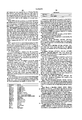
- FIG. 2 depicts the pin package and the various inputs and outputs, to/from the novel ICU.
- FIG. 3 is a data flow diagram depicting data flow between the processor bus unit and memory bus unit of FIG. 1, via the novel ICU.
- FIG. 4 depicts a simplified shared bus multiprocessor system with two ICUs per processor, one used as an instruction cache, the other used as a data cache.
- FIG. 1 depicts a typical computing system configuration that would include the novel ICU.
- FIG. 1 depicts two of the new ICUs. ICU 101 is shown being used as an instruction cache, while ICU 102 is shown being used as a data cache.
- the incorporated application also teaches the various operating modes of the SIP, processor inputs and outputs, etc. which will be referenced herein and will be shown as supported by the novel ICU.
- FIG. 1 goes on to show the processor bus comprised of Address Bus 120 and Data Bus 121. Instructions in Instruction ROM 150 and the instruction cache, ICU 101, are addressed by processor 110 via Address Bus 120. Instructions fetched are shown transmitted to processor 110 via bus 125.
- the data cache, ICU 102 is also addressed via Address Bus 120. Bidirectional data flow is shown possible between processor 110 and ICU 102 via Data Bus 121.
- Memory Bus 175 is shown as the bus coupling main memory 190 with ICU 101 and ICU 102.
- arithmetic accelerator 195 which would be part of a typical RISC system configuration, is shown coupled to buses 120 and 121.
- Data Transfer Controllers (DTCs) shown as DTC 198 may be used as part of a typical system configuration to, for example, allow commercially available peripheral devices having speeds much lower then the high speed processor, to be attached to the system without limiting the performance of the processor, cache units, etc.
- DTCs Data Transfer Controllers
- the DTC is described in detail in copending application Ser. No. 132,996, filed Dec. 15, 1987 and assigned to the same assignee as the instant invention.
- a typical arithmetic accellerator is described in copending application Ser. No. 771,385, filed Aug. 30, 1985, also assigned to the same assignee as the instant invention.
- Block--A cache block is a group of sequential words associated with a tag.
- a cache block is allocated and replaced as a group whenever required.
- the block size is four words (one tag per four words).
- Block status--Status bits which are associated with a cache block. According to the preferred embodiment of the ICU, there are two status bits per block. They specify the modified and shared status of a block.
- Block status array--An on chip random access memory array that contains the block status bits.
- Copy-back--A write policy in which a write access is performed only in the cache, for the case of hit.
- the block which includes the written data is marked as modified.
- the data is written (copied back) to the main memory only when the modified block is replaced.
- Data cache--A cache which is used for caching frequently used processor data variables.
- Direct-mapped-- This is an alternate term for a one-way set-associative organization.
- a specific address can be cached only in one specific location (directly mapped by the address) in the cache.
- Hit--The word specified by the access address is present in the cache memory array. An address match is found in the tag array, and the corresponding valid bit is set.
- Invalidate--An operation that removes valid data from the cache.
- One or more valid bits are reset, so that the corresponding words become invalid.
- Instruction cache--A cache which is used for caching frequently used processor instructions.
- LRU Least recently used
- Lock in cache--Data variables or instructions can be locked in the cache. They will not be replaced even if they are chosen by the replacement algorithm.
- *LOCK input to the ICU specifies interlock operations, and it is not used for lock in cache operations.
- a lock bit is associated with each block to facilitate locking the block.
- Memory array--On chip random access memory array that contains the cached data or instructions.
- Memory bus The bus that connects the cache to the main memory.
- Miss--The word specified by the access address is not present in the cache memory array.
- Modified block--A block is marked as modified when it is written in a copy-back write policy. This indicates that the block is modified relative to the main memory, and contains the more recent version of the data.
- Non-cacheable--An instruction or data variable which cannot be cached A non-cacheable operation is transferred by the ICU to the memory bus. The cache is not searched for it, and no cache block is allocated.
- Prefetch buffer--A buffer which holds prefetched data variables or instructions read from the memory bus, before they are written into the cache.
- the read buffer is used for the function of a prefetch buffer.
- Preload--A special prefetch operation that loads the cache with specific data variables or instructions.
- the addresses for the preload operation are specified by the user as opposed to other prefetch operations in which the prefetched addresses are determined by the cache.
- Processor bus The bus that connects the cache to the processor.
- Random replacement--A replacement algorithm in which the block to be replaced is chosen randomly.
- Read buffer--A buffer which holds data variables or instructions read from the memory bus, before they are written into the cache.
- the read buffer is four words deep, and it is also used for the function of a prefetch buffer.
- the reload operation is completed in parallel. In a cache with no read-through, the reload operation is completed before the required data or instruction is transferred to the processor.
- Replacement algorithm The algorithm that determines the block to be replaced when a new block is allocated in the cache. One block from the set that contains the required new address is chosen.
- Scope--This term is used in the context of cache instruction to define the scope of the instruction effect.
- the instruction can affect one specific ICU, multiple instruction caches, multiple data caches, or multiple instruction and data caches.
- Set--A group of tags and the associated cache blocks which are read and compared concurrently to the requested address. A match can be found to any of the set's tags.
- the set is specified according to some of the address bits.
- the number of tags in the set is equal to the number of "ways", (to be defined hereinafter), in the cache organization.
- Set-associative--A cache organization which allows caching of a specific address in a number of possible locations in the cache. This number is referred to as the degree of associativity. It specifies the number of "ways" in the cache organization and the number of tags which are read and compared concurrently.
- the disclosed ICU supports two-way and one-way set-associative organizations.
- the sub-block size defines the maximum number of words that are fetched.
- the sub-block size is lower or equal to the block size.
- Tag--The tag identifies the address of the data or instruction which is currently present in the cache.
- a cache tag is associated with each cache block, and it is stored in the tag array.
- each tag corresponds to a four-word block.
- Tag array--On chip random access memory array that contains the address tags for the cached data or instructions.
- Update memory--An operation that causes the update of the main memory from the cache.
- a modified block is written by the cache to the main memory so that the memory is updated with the most current version of the data.
- Valid array--On chip random access memory array that contains the valid bits.
- Valid bit--A bit that indicates the validity of the cached data.
- a valid bit is associated with each cached word.
- Way--A group of tags associated with a tag array module Only one tag specified by the module's address decoder is read and compared from each way. In the preferred embodiment of the ICU there are two ways, each containing 256 tags.
- Write buffer--A buffer which holds write accesses information (address, data, and control) until the write access is performed on the memory bus.
- the preferred embodiment of the ICU includes a four deep write buffer that can hold up to four write accesses.
- bus snooping or snooping cache are equivalent.
- Data intervention--An operation that can be performed by a slave cache when a match is found in the case of memory-bus read access. If the slave cache contains modified data (the most current version of the data), it intervenes in the access and supplies the data. In this case the main memory should not supply the data.
- a LOW in the shared block status bit indicates an exclusive block.
- the block can be either exclusive non-modified or exclusive modified.
- Interlock--Interlock operations are used for temporarily locking a variable (interlock variable) for exclusive usage of one processor. No other processors or caches are allowed to use the variable while it is interlocked.
- the *LOCK input to the ICU, to be described hereinafter, indicates an interlock operation.
- Master cache--A cache which is a master of the memory bus. It issues the request and expects a response.
- Ownership--This is a scheme to guarantee data consistency. The most current value of a variable is owned by one cache or the main memory. It is the responsibility of the owner to maintain the consistency of the variable. There are several ownership schemes which differ in the number of states that are attributed to a variable and the algorithms for ownership and state transitions.
- a shared variable can be present in more than one cache.
- a HIGH in the shared block status bit indicates a shared block.
- the block can be either shared non-modified or shared modified.
- Shared modified--A block status in the ICU which indicates that a cache block is shared and modified. It also indicates that the block is owned by the cache, and that it is the most current value of the block in the system.
- Slave cache--A cache which is not the master of the memory bus.
- a slave cache can monitor the memory bus for data consistency purposes.
- Bus snooping or snooping cache are also equivalent.
- the preferred embodiment of the novel ICU is a CMOS; 169 Pin Grid Array package as shown in FIG. 2.
- the processor bus interface will first be described and includes the following:
- the Address Bus pins A0-A31 of FIG. 2, is an ICU input, is synchronous, and transfers the byte address for the cache access on the processor bus.
- the Access Status Control signals shown as ASTC0 and ASTC1 in FIG. 2, are synchronous inputs which specify the status control associated with an access. They are encoded, according to the preferred embodiment of the invention, as follows:
- processor 110 These inputs are normally connected to processor 110's MPGM0-MPGM1 outputs as described in the incorporated application describing processor outputs.
- Bus Invalid is a synchronous ICU input, active LOW, indicating that the address bus and related controls are invalid. It defines an idle cycle on Processor Bus 120.
- Cache Burst Acknowledge is an ICU output, synchronous, and active LOW. This output is asserted whenever a burst-mode cache access has been established on Processor Bus 120.
- *CBREQ Cache Burst Request
- This input is used to establish a burst-mode cache access on the processor bus and to request the next transfer during a burst-mode cache access.
- This signal can become valid late in the cycle compared to *DREQ or *IREQ, to be described hereinafter.
- CREQT0-CREQT1 Cache Request Type
- CREQT1 has a special function. It is sampled during RESET, and if the sampled value is HIGH, the ICU responds to instruction ROM accesses. If the sampled value is LOW, the ICU doesn not respond to instruction ROM accesses. After RESET the CREQT1 input is ignored for instruction cache usage.
- *CSEL, Chip Select is a synchronous input, active LOW. An active level on the *CSEL input selects the ICU for processor-bus cache instruction accesses. It is not used in normal memory accesses.
- the *CSEL input can be disabled via the Chip Select Mapping Register, a portion of the ICU to be described hereinafter. When *CSEL is enabled and not asserted the ICU does not respond to processor-bus cache instruction accesses.
- *CSM, Chip Select for Memory access is a synchronous ICU input, active LOW. An active level on the *CSM input selects the ICU for memory accesses. It can be used for cache extensions and cache address space selection.
- the *CSM input can be enabled via the Chip Select Mapping Register. When *CSM is enabled, The ICU responds to memory accesses only if the *CSM is asserted and the address matches corresponding enabled bits in the preselected field of the Chip Select Mapping Register (to be described in detail hereinafter).
- the Cache Bus is bidirectional, synchronous and three state.
- the Cache Bus transfers instructions or data to and from the ICU on the processor bus.
- *DREQ Data Request
- This input requests a data access on the processor bus. When it is active, the address for the access appears on the Address Bus.
- *DREQ is used for processor-bus cache instruction transfers.
- *IREQ Instruction Request
- This input is a synchronous ICU input, active LOW. This input requests an instruction cache access on the processor bus. When it is active the address for the access appears on the Address Bus. This input has a special function during reset operation of the ICU. It is sampled by the rising edge of SYSCLK, when RESET (to be described hereinafter) is active. The last sampled value determines the ICU operation as a data cache (*IREQ LOW), or as an instruction cache (*IREQ HIGH). For data cache operation, *IREQ should be tied LOW (it is ignored during normal operation). For instruction cache operation, it should be connected to the processor *IREQ output, which is deasserted during RESET. Note that if the processor is placed in Test Mode during RESET, external logic should drive the IREQ HIGH (the processor described in the copending application regarding the high performance interface does not drive IREQ HIGH in its Test Mode).
- *LOCK, Lock is an ICU input, synchronous and active LOW. This input indicates that the processor cache access is to an interlocked variable.
- the ICU handles this access in a special way to be described with reference to the interlock facility set forth in detail hereinafter.
- MSERR Master/Slave Error
- OPT0-OPT2 is a synchronous ICU input. These signals reflect the option control bits associated with a cache access. They are used for specifying the data length as well as special access information. The interpretation of these signals is dependent on the usage of the ICU as data or instruction cache. The encoding and interpretation of these inputs, according to the preferred embodiment of the invention, is as follows:
- Codes 100, 101 are treated as no access if DREQT0 is HIGH.
- Code 100 is used for reading the instruction ROM as data.
- a data cache responds to this code only if the ROM Enable bit in Moda Register, to be defined hereinafter, is HIGH. In this case the request is treated as a non cacheable access.
- Code 101 indicates an operand transfer for the ICU processor-bus cache instructions.
- code 110 is used for a special debug module access.
- a data cache responds with *CRDY HIGH for four cycles, and then *CRDY is asserted for one cycle.
- *PCA Pipelined Cache Access
- *DREQ for data cache or *IREQ for instruction cache is not active
- this input indicates that the cache access is pipelined with another, in-progress, cache access.
- the pipelined access cannot complete until the first access is complete.
- the completion of the first access is signalled by the assertion of *DREQ for data cache and *IREQ for instruction cache.
- R/*W Read/Write
- This input indicates whether the cache access is a transfer from the ICU to the processor (R/*W High), or from the processor to the ICU (R/*W Low).
- SUP/*US, Supervisor/User Mode is a synchronous input. This input indicates the program mode of the illustrative processor (Supervisor mode or User mode) during the access.
- the ICU internal registers and the execution of cache instructions are protected from User mode accesses.
- SYSCLK, System Clock is an external clock input, at the operating frequency of the ICU.
- WREP Way for Replacement
- This input forces the way number for replacement in a case of a cache miss. It is sampled during the first cycle of a valid cache access.
- a miss in a two-way set associative organization causes replacement as determined by WREP: WREP LOW forces way 0 to be replaced, WREP HIGH forces way 1 to be replaced.
- the memory bus may be seen to include:
- Block Status Control which is bi-directional, synchronous and three state. These signals are used to inspect and update the cache block status information. When required by a memory bus instruction, the ICU uses them to indicate the block status bits associated with the supplied address. These signals are also used for supplying the block status from the memory bus for a Write Block Status instruction. The encoding of this signal for both of the above functions is as follows:
- *DI, Data Intervention is a synchronous output, three state and active LOW. This output is used for the indication of a data intervention operation on the memory bus.
- the data intervention operation is used in some multiprocessor configurations, to supply the most updated version of the variable from the appropriate cache (as opposed to memory).
- the ICU master precharges the *DI signal during the address cycle of a memory bus read access. It then places it in three state mode. The ICUs which are not the bus masters, discharge the *DI signal if they respond with data intervention.
- Hit is bidirectional, synchronous, three state and acitve LOW.
- This signal can be programmed to be either an output only or an input/output signal. As an output it is used for hit indication. It is asserted when a hit is detected in the tag buffer for the address presented on the memory bus. It is also used in some of the memory bus instruction, to indicate the validity of a word or a block.
- the ICU master When programmed to be an input/output signal it can be used, in addition to the above output functions, as a signal for the detection of hit in any other cache.
- the ICU master precharges the *HIT signal during the address cycle and then places it in input three state mode.
- the ICUs which are not the bus masters discharge the *HIT signal only when a hit is detected in their tag buffer.
- *MASTB Memory Address Strobe
- ICU Memory Bus master
- this signal is asserted by the ICU to indicate that a byte address is present on the memory bus.
- this signal indicates that a byte address from another bus master is present on the memory bus. Note that if both instruction cache and data cache are present in the system, two *MASTB signals are available. The two signals can be used to distinguish between instruction and data accesses.
- MBP0-MBP3, Memory Byte Parity is bidirectional, synchronous and three state. This is the byte parity bus for transfers on the memory bus. Even or odd parity can be specified. MBP0 is the byte parity for MEMAD0-MEMAD7, MBP1 is the byte parity for MEMAD8-MEMAD15, and so on. For transfers from the ICU to the memory, the ICU generates parity. For transfers to the ICU, it checks the byte parity.
- the *CERR signal is asserted. If the data need not be transferred to the processor (e.g. block reload), an error bit is set in the Status Register (to be described hereinafter) and the data is ignored.
- the parity generation and checking can be disabled. Memory bus data timing are relaxed if parity generation and verification is disabled.
- Memory Burst Request is bidirectional, synchronous, three state and active LOW. This signal is used to establish a burst-mode access on the memory bus and to request the next transfer during the burst-mode access. When the ICU is the bus master, this signal is an output. When the ICU is not a master, it is an input, used by the ICU for data consistency operations.
- MDLN0-MDLN1 Memory Data Length
- MDLN0-MDLN1 Memory Data Length
- MDLN0 and MDLN1 encoding corresponds to OPT0 and OPT1 for the processor used with the illustrative embodiment of the invention.
- MEMAD0-MEMAD31 Memory Address/Data Bus
- the Memory bus is a multiplexed Address/Data bus used for the memory interface. When *MASTB is asserted, this bus holds the byte address of the Memory Bus access. When the ICU is the bus master, it outputs the address. When the ICU is not the bus master the bus is an input and the address is latched by the ICU for its internal use. When MASTB is not asserted, the memory bus is used to transfer data to and from the ICU.
- *MCLOCK, Memory Lock is bidriectional, synchronous, three state and active LOW. This signal indicates that the memory access is an interlocked access.
- the ICU master asserts this output when an interlocked access is presented on the memory bus. When the ICU is not the bus master, this signal is used as an input. If a match is found for a write access with *MLOCK asserted, the associated word is invalidated. This feature is used for schemes that enable caching of interlock variables.
- *MRDY, Memory Ready, is bidirectional, synchronous and active LOW.
- this signal is used as an input.
- this input indicates that valid data is present on the memory bus.
- this signal is used as an input for data consistency operations. It is used as an output for data intervention and memory bus special operations.
- the ICU asserts *MRDY to indicate that valid data is present on the memory bus.
- MREQT0-MREQT1 Memory Request Type
- the MREQT signals are also used (together with the MRW signals) for specifying a memory bus cache instruction for the ICU.
- MRW0-MRW1 Memory Read Write
- ICU is the bus master, it uses these signals to indicate the required operation.
- ICU is not the bus master these signals are inputs, used for data consistency operations.
- the encoding of these signals is as follows:
- the read and write operations referred to hereinabove are relative to the ICU, e.g. read is from the memory to the ICU.
- the MRW signals are also used (together with the MREQT signals) for specifying the memory bus cache instruction for the ICU.
- MREQT signals are also used (together with the MREQT signals) for specifying the memory bus cache instruction for the ICU.
- MS/*MU Memory Supervisor/User Mode
- This output indicates the program mode of the processor (Supervisor mode or User mode) during the memory access.
- the ICU transfers the SUP/*US value presented on the processor bus to the MS/*MU value on the memory bus, for the appropriate transactions.
- *VSI, Valid Status or Instruction is a synchronous ICU input, active LOW.
- an asserted *VSI indicates a memory bus cache instruction access.
- the ICU is the bus master and it issues a read request for a reload operation, the assertion of *VSI indicates that a special Write Block Status instruction should be executed.
- the novel ICU is described in the context of a RISC architecture including a SIP.
- the preferred embodiment of the invention is described in such a way as to support this architecture.
- modifications may be made to the preferred embodiment of the novel ICU, without departing from the scope of spirit of the invention, to support, for example, non-RISC processors.
- the description to follow is, accordingly, set forth for the purpose of illustration only.
- the core of the preferred embodiment of the ICU is an 8k byte memory array with the associated tag and valid arrays.
- This basic organization also supports direct mapped cache, variable block and sub-block size as well as a flexible reload scheme.
- a block status array and LRU array are also incorporated. They are used for cache replacement, locking data in cache, and data consistency policies.
- the ICU contains all the control logic for the different cache policies, algorithm and instructions. Special registers are implemented for programmable option selection, cache instructions implementation and status report.
- Cache policies can be selected by using programmable options.
- the cache write policy can be programmed as write-through, copy-back or flexible on a per access basis.
- a write allocate or nonwrite allocate option can be selected.
- a four word write buffer is incorporated for efficient implementation of write accesses.
- the write buffer can be enabled or disabled.
- the replacement algorithm can be programmed as LRU, random or external.
- a flexible prefetch policy can be selected.
- Read through option can be enabled.
- a four word read buffer is incorporated to support efficient prefetching and read operations.
- the multiprocessor support policy can be tailored to the system.
- the level of multiprocessor support can vary from a simple software controlled organization through an extensive ownership scheme.
- a bus watch capability can be enabled or disabled.
- the ownership algorithm can be controlled to support the required scheme.
- Caching interlock variables can be enabled or disabled.
- Two chip select inputs and a chip select mapping register allows easy cache extensions as well as multi cache organizations.
- the reload function can be tailored to the system by selecting the appropriate access control options such as reload size, starting and stopping addresses, burst and wrap around.
- the preferred embodiment of the ICU operates at the same frequency of the RISC processor in the illustrative example being set forth, i.e., at a 25 MHZ. nominal frequency with possible higher frequencies. It achieves access times of two cycles for the first hit access and one cycle for the next burst-mode or pipeline hit accesses.
- a three IC configuration one containing the RISC processor and two for ICUs (one for an instruction cache and one for a data cache) is a very high performance cache system with 16k bytes of cache.
- the ICU has two interface busses; the Processor Bus and the Memory Bus. It can be connected directly to the RISC processor without any interface logic.
- the ICU cache bus is connected to the processor's data or instruction bus, for data or instruction cache respectively. Pipelined and burst-mode accesses are supported for maximum utilization of the processor channel.
- the Memory Bus is a separate interface to the memory, other processors, and the system bus. It is a multiplexed address and data bus with support for burst-mode accesses. It also incorporates multiprocessor support functions. In shared memory multiprocessor environments the memory bus can be used effectively as a shared multiprocessor bus. For single processor systems it can be used as the system bus or as a local bus.
- the preferred embodiment of the ICU contains special hardware for fault tolerance support. It supports master/slave checking and byte parity generation and checking on the memory bus. For master/slave checking two or more ICUs are connected in parallel with one or more caches (the slaves) checking the outputs of the master. The byte parity generation and checking can be used on the memory bus for reliable bus transfers.
- the preferred embodiment of the invention is, as indicated hereinbefore, fabricated in CMOS technology and has a maximum power dissipation of 1.5 W.
- the ICU internal data flow organization is shown in FIG. 3.
- the following description refers to the functional components on this data flow diagram.
- the ICU is partitioned into three main functional units: Processor Bus Unit, Memory Bus Unit and Cache Unit, each depicted in FIG. 3.
- Processor Bus Unit Processor Bus Unit
- Memory Bus Unit Memory Bus Unit
- Cache Unit Cache Unit
- the Processor Bus Unit controls all the Processor Bus activity. It supports all RISC/SIP channel protocols; single, burst and pipelined. It incorporates the Address Incrementer, the Data Shifter and the Processor Bus Control, each to be described immediately hereinafter.
- the Address Incrementer latches the address bus input. It can be incremented on every cycle.
- the AI output is the address for a cache access.
- the AI is shown in FIG. 3 as unit 301.
- the Data Shifter is used for data alignment. It shifts bytes and halfwords and holds the data for cache write accesses. It is also used for the appropriate byte and half-word shift operation in the case of byte and half-word reads.
- the DSH is shown in FIG. 3 as unit 302.
- the Processor Bus Control controls the different Processor Bus operations.
- the PBC is shown in FIG. 3 as unit 303.
- the Memory Bus Unit controls Memory Bus activity. It incorporates the Write Buffer, the Memory Address logic, the Memory Read Buffer and Memory Bus Control, each to be described immediately hereinafter.
- the Wrtie Buffer (WB) used in the preferred embodiment of the invention includes two four word first-in, first-out (FIFO) buffers (one for address and one for data).
- the WB can buffer all ICU write operations. For write through operations it buffers up to 4 byte, half word or word writes. For copy-back operations it buffers a 4 word block.
- the WB is shown in FIG. 3 as unit 304.
- the Memory Address Logic includes two address incrementers. The first latches and increments the memory bus addresses for operations from the bus to the ICU. The second latches and increments the addresses for read operations initiated by the ICU.
- the MAL is shown in FIG. 3 as unit 305.
- the Memory Read Buffer is a four word data buffer. It buffers the data from the memory bus, until the cache is available for update operation.
- the MRB is used as a prefetch buffer when prefetching is enabled.
- the MRB is shown in FIG. 3 as unit 306.
- MBC Memory Bus Control
- the cache unit performs all the cache functions. It incorporates the Memory array, Tag array, Valid array, Block Status array, LRU array, Special Registers, and Cache Control, each to be described immediately hereinafter.
- the Memory array is a 64k bits storage array for cached instructions or data. It is organized as two ways of 1024 words. For read operations the two ways are accessed simultaneously, according to the preferred embodiment of the invention, using bits 11-2 of the address. The appropriate word is selected according to the hit signals from the Tag array. For write operations the correct word in the array is written after the Tag access is completed and the hit signals generated.
- the Memory array is shown in FIG. 3 as unit 310.
- the Tag array stores cache tags in a two way set associative organization. Each way is organized as 256 ⁇ 20 bits. Each tag corresponds to a block of 4 consecutive cached words. For each cache access, two tags are accessed simultaneously using bits 11-4 of the address. The tags are compared to bits 31-12 (in one embodiment of the invention) of the address. The hit signals are generated from the comparison results and configuration bits. The Tag array is written whenever a miss occurs and a cache block is allocated. The tag is selected according to bits 11-4 of the address and the replacement algorithm. Address bits 31-12 are written to the Tag array.
- the Tag array is shown in FIG. 3 as unit 311.
- the Valid array, unit 312 of FIG. 3, is a 2k bit array that stores a valid bit for each cached word. It is organized as two 1024 ⁇ 1 arrays. A valid bit is set for each word as it is written into the cache. The valid bit is selected by address bits 11-2 (as is the memory array), and the matching way. Two valid bits corresponding to the two ways are checked on every cache access. A hit signal is generated only if the appropriate valid bit is set.
- the Block Status array, unit 313 of FIG. 3, is a 1536 bit array that incorporates 3 block status bits per each cache block. It is organized as two 256 ⁇ 3 arrays (this corresponds to the Tag array organization).
- the three bits are: Modified, Shared and Locked.
- the Modified bit indicates that the block is modified and should be written back to memory before replacement. It is used for copy-back operations and data consistency operations.
- the Shared bit indicates that the block is shared. It is used for data consistency operations.
- the Locked bit indicates that the block is locked and cannot be replaced. It is used for locking important data or instructions in the cache.
- the LRU array, unit 314 of FIG. 3, is a 256 bit array which stores the LRU bits. It is organized as a 256 ⁇ 1 array. Each LRU bit corresponds to a set of two tags. The LRU array is used if the Least Recently Used replacement algorithm is selected. The appropriate LRU bit is updated to reflect the least recently used block of the two blocks in a set. When required, the LRU bit determines which block is replaced from the set.
- the Special Registers block shown as unit 315 of FIG. 3, incorporates all the special registers of the ICU. They are used for programming the ICU options, controlling special operations, and holding status information.
- Cache Control block unit 316 of FIG. 3, includes control logic for the cache operations.
- the preferred embodiment of the ICU contains 8 special registers. These registers select programmable options, support cache control operations, and indicate cache status information. Each register can be read or written by the processor via the processor bus or the memory bus. A read register or write register cache instruction is transferred to the ICU using the appropriate cache instructions protocol on one of the buses. For the processor-bus instructions, the register number is specified by the three least significant bits of the opcode. The instruction transfer protocol and the ICU response are controlled by the Read Registers Control and Instruction Transfer Protocol Control in the Modb Register respectively. For the memory-bus instruction the register number is specified by the three least significant bits of the address. A detailed description of the these illustrative protocols and responses will be set forth hereinafter.
- ICU special registers are protected. They can be accessed only if the SUP/*US input is HIGH. User mode accesses are not executed. A *CERR response signals an invalid User mode access. The registers are not protected for the memory bus cache instruction.
- each register is assigned a number as follows:
- the Chip Select Mapping Register is special register 0. It specifies the address and the conditions for the ICU chip select functions.
- the ICU has two independent chip-select functions: for normal cache accesses and for cache instruction accesses.
- the chip-select function can be used for cache extensions, cache address space assignments, and multiple-cache configurations. In the preferred embodiment of the invention, up to 32 ICUs (16 instruction caches and 16 data caches) can be used without external chip-select hardware.
- Memory access (MA) selection is also affected by the *CSM input and a Memory Bit Enable field of the Moda Register. If the *CSM input is enabled, it must be asserted to enable a memory access. If the *CSM input is disabled, it is ignored.
- the Memory Bit Enable Field can selectively enable the comparison of an appropriate address bit to a corresponding (MA) field bit in the chip-select memory register. When a bit is disabled for comparison, it is ignored. If all the bits are disabled, a match is forced. Note that when the *CSM is enabled, it should be asserted and the MA field comparison match, for a memory access to be serviced.
- the chip-select function is used for selecting the appropriate ICU for the access.
- a cache instruction access is enabled when *CSEL is asserted and enabled, or when the address inputs A31-A14 and CREQT0 match Cache Instructions Address and Cache Instruction Address Space fields in the Chip Select Mapping Register. In the second case, all the caches with a match are selected. If the instruction scope is multiple caches, all the selected caches respond. If the instruction scope is one cache, only the cache where the address inputs A13-A8 match a Specific Cache Number field of the Chip Select Mapping Register, responds.
- the *CSEL input is used to program the Chip Select Mapping Registers of a given ICU.
- a different address bit can be connected to the *CSEL of different ICUs.
- *CSEL When *CSEL is asserted and enabled, the ICU treats data accesses as cache instruction accesses.
- the Chip Select Mapping Register After the Chip Select Mapping Register is programmed, the *CSEL input can be disabled, and the mapping specified by the Chip Select Mapping Register applies.
- the Instruction Register is special register 1. It is used for specifying an instruction to the ICU.
- the Instruction Register can be read or written as any other special register, however, it is also loaded automatically for a valid cache instruction.
- a valid cache instruction is detected when the *CSEL input is asserted and enabled or when the address inputs A31-A14 and CREQT0 match the Cache Instructions Address and Cache Instructions Address Space fields in the Chip Select Mapping Register. In these cases, the instruction is copied from the address inputs A7-A0.
- the Instruction Register can be accessed as a special register for saving and restoring the ICU state in the case of a processor interrupt during the instruction transfer protocol, or if a multiple cache instruction is interrupted. When it is accessed as a special register, a Read or Write Register cache instruction is transferred to the ICU. Shadow registers are incorporated in order to be able to latch the Read Register instruction and optional operand, without destroying the required old contents of the Instruction and Operand Register.
- the shadow Instruction Register is first loaded with an instruction. For all the instructions except the Read Register and the Write Register instructions, the Instruction Register is updated when the instruction execution is started. For the Read Register and Write Register instructions the Instruction Register is updated only if there is no other valid instruction in the Instruction Register. If a valid instruction is present in the Instruction Register, the Read Register instruction is executed without affecting the Instruction and Operand registers. This feature is also used for checking the status of the ICU without affecting the execution of a cache instruction.
- An instruction is executed by the ICU whenever all the required operands are valid.
- An instruction is executed by the ICU whenever all the required operands are valid.
- the Operand Register is special register 2. It specifies an operand for certain ICU instructions.
- the register contains a bit (OV bit) to indicate the validity of the Operand Register value.
- a shadow Operand Register is incorporated in the ICU for correct execution of Read Register and Write Register instructions.
- the shadow Operand Register is first loaded with an operand. For all the instructions, except Read Register and Write Register instructions, the Operand Register is updated if the validity bit is reset. If the OV bit is set, the ICU delays the *CRDY response until the OV bit is reset (the previous instruction completion), and then loads the register. For Read Register or Write Register instructions the Operand Register is updated only if there is no other valid instruction in the Instruction Register.
- the Read Register and Write Register instructions are executed without affecting the Instruction and Operand registers. This enables saving and restoring the Operand Register, when required. When required, the Operand Register can be read or written by using Read Register or Write Register instructions.
- the Count Register is special register 3. It specifies the number of words to be operated on by certain ICU instructions. The Count Register is not affected by the instruction execution.
- the Exception Address Register is special register 4. It is used for reporting the address associated with some exceptions.
- the Exception Address register is loaded with the exception address.
- the exception type can be found in the Status Register.
- the Status Register is special register 5. It is used for reporting the status of the ICU, and for information transfer between the ICU and the processor in the Read Tag and Write Tag cache instructions (to be explained hereinafter). Bits are reserved for reporting the tag value for the Read Tag instruction and for transferring the tag for the Write Tag instruction; for the reporting of the WAY for cached data; for reporting the valid bits for a block and for transferring the valid bits for the Write Tag instruction; for reporting the locked bit for the block and for transferring the locked bit for the Write Tag instruction; for reporting the shared bit for the block and for transferring the shared bit for the Write Tag instruction; for reporting the modified bit for the block and for transferring the modified bit for the Write Tag instruction; for indicating if a hit is found in the cache; and for indicating protection violations; illegal instructions; memory errors and parity error.
- the Moda Register is special register 6. It is used for selecting various ICU options. The Moda register is reset during initialization.
- Fields are set aside to: control global cache operation; to lock all cache locations; to disable the write buffer; and to disable the read through option.
- a ROM enable bit is included in this register which has different functions for instruction cache and data cache usage ("ROME" bit).
- the ICU For instruction cache usage when this bit is set, the ICU responds to ROM accesses and caches them. When it is 0, ROM accesses are ignored.
- the data cache is enabled for instruction memory accesses (as data).
- the OPT inputs indicate an instruction memory access
- the ICU treats it as a non-cacheable transaction.
- the specified address is read on the memory bus and transferred to the processor, without loading it into the cache.
- the ROME bit is 0, the ICU ignores this type of transaction.
- Further fields are provided in the register to enable the prefetch option for single accesses; to disable an address wrap around option; to control the ICU operation on a single access miss; to control the ICU operation when a burst mode read request is terminated by the processor; to enable the prefetch option for burst accesses; and to select sub-block size (SBS).
- SBS sub-block size
- the sub-block size is used in the control of cache reload operations.
- the number of words to be reloaded into the cache for a single cache miss is defined by the defined sub-block size and the information stored in the field controlling ICU operation for an access miss (for example, control information such as start and stop on a sub-block boundry).
- the SBS field is also used, together with the burst mode control information, in the burst end control.
- the inherent block size of the ICU is 4 words, one tag is associated with four data words.
- the sub-block size is either 1, 2 or 4 words.
- the Moda Register contains fields for controlling the extension of memory bus address transfers; for indicating whether a write allocate option is on; and for selecting the write policy options on a global basis.
- the write policies are: flexible, write-through or copy-back.
- every processor write to the ICU is also written to the memory.
- every processor write hit is written in the cache and the modified bit set.
- the block is copies back to memory only when the block is replaced.
- a write-through or copy-back operation can be selected on an access by access basis.
- the write policy for an access is also affected by the ASTC inputs, the block status shared information, and the Write Shared Hit Control and the Processor Status Bit Control fields of the Modb Register (to be explained hereinafter).
- the Moda Register also contains a field used to select the block replacement policy.
- the selection is not used for direct-mapped organization. In a two-way set-associative organization, if one of the blocks is not valid, it is chosen for the new block.
- the replacement policy options are: Least Recently Used (LRU), random, or external.
- the LRU array is used for the selection of the block to be replaced.
- the LRU array is updated on each cache access. One bit is associated with each set. It points to the least recently used block from the two blocks in a set.
- a pseudo random logic selects the block to be replaced.
- the logic is a simple flip flop which change state every clock cycle, and used for all the sets.
- the WREP input is latched with the processor address.
- the latched value forces the replaced block selection. This option may be used for cache testing and multi-level cache organizations.
- the Moda Register contains fields for selecting the cache organization (two-way set-associative or direct-mapped); for selecting the cache operation as Instruction Cache or Data Cache; for controlling parity generation and checking options and memory bit enable information for enabling the corresponding MA bits in the Chip Select Mapping Register for address comparison on Memory accesses.
- the Modb Register is special register 7. It is used for the selection of various ICU options.
- One field of the Modb Register is assoicated with multiprocessor organizations. A detailed description of multiprocessor organizations and the usage of this field will be described hereinafter.
- the Modb Register also contains a bit for controlling the ICU for Input/Output data accesses on the processor bus (it is ignored in instruction cache usage); a bit which specifies the mode of reading the ICU registers; a bit which specifies the protocol for cache instruction transfer on the processor bus; and a bit which controls the byte and half-word ordering within a word, for the relevant ICU operations.
- the multiprocessor oriented information in the Modb Register includes: a Cache Interlocked Enable bit; a Read Bus Watch Enable bit; a Write Bus Watch Enable; a field which controls the operation of the ICU in the case of a match on memory bus read by another master; a field which controls the operation on match for memory bus write operation by another master; a Write Miss Memory Access Control which controls the memory bus operation of the ICU for a copy-back write miss with write-allocate; a Write Shared Hit Control field which controls the operation on a write hit to a shared block; a Processor Shared Bit Control which causes the block status share bit to be modified for every processor access when set; and an External Shared Bit Control which controls the assignment of the shared block stauts by external control.
- the *HIT signal is used as an input for memory bus read and/or write accesses. If it is asserted, then the data is also present in other caches, and the block is assigned a shared status. If the *HIT input is not asserted, the variable is not present in any cache and the block is assigned an exclusive status. Detailed description of this feature is set forth hereinafter with reference to ICU multiprocessor support.
- the preferred embodiment of the ICU implements 20 processor bus cache instructions, and 9 memory bus cache instructions.
- the processor bus instructions are issued by the processor for special register accesses and for special cache operation requests.
- the memory bus instructions are issued by special logic on the memory bus for special cache operation requests. This section sets forth examples of different instruction transfer protocols and sets forth an example of a typical processor bus instruction and a memory bus instruction set, in detail.
- the processor bus cache instructions and operands are transferred to the ICU from the processor by a special sequence of processor bus transactions.
- the instruction is executed whenever all the required operands are transferred to the ICU.
- the instruction scope specifies the number of ICUs which are affected by a cache instruction.
- the scope is designated by (s) in the instruction table.
- the instructions without the (s) indication can operate only on one specific ICU.
- the instruction scope can be designated as follows:
- processor bus cache instruction execution the ICU can accept other processor transactions, (including new instruction transfers) but in most cases (unless otherwise specified in the instruction description) they are serviced only after the processor bus cache instruction completes. Memory bus transactions are serviced during the processor bus cache instruction execution. However, since they are not synchronized to instruction execution, the ICU operation reflects the current state of the cache.
- All processor bus cache instructions are privileged. If the SUP/*US input is LOW, when the processor bus cache instruction access is performed, it is ignored and the *CERR asserted as a response.
- the Status Register is updated with status information for the relevant instructions. In case of an exception the Exception Address Register and the Status Register are updated with the exception information.
- the protocol is defined according to the Instruction Transfer Protocol Control (ITPC) and Read Register Control (RRC) bits of the Modb Register as well as the cache instruction type and scope. All instructions, except Read Register, are transferred by using a write operation.
- the Read Registers instruction is transferred by using a read or write operation as defined by the Read Register Control bit of the Modb Register.
- a processor bus cache instruction request can be either a read or write processor bus access. It is detected by the ICU in two cases: 1) The *CSEL is asserted and enabled or 2) the address inputs and CREQT0 match the Cache Instruction Address and Cache Instruction Address Space fields in the Chip Select Mapping Register.
- the protocol is selected according to the Instruction Transfer Protocol Control bit of the Modb Register.
- the cache bus is used for the operand transfer.
- the processor uses a normal write operation, and the processor address and data buses are both used.
- the ICU latches the operand value from the cache bus.
- external transceivers are required for transferring the data from the ICU data bus to the cache bus. This option is the natural selection for ICU used as a data cache. A more efficient protocol is also achieved for ICU used as an instruction cache in the expense of external transceivers.
- Both options can be selected independently for ICU used as a data cache or an instruction cache. However, from system programming point of view, it might be desirable to access both caches in a similar way. If this is the case, both caches can be programmed to respond to the same protocol.
- a Write Register Instruction should be executed for writing it to the Count Register before the instruction execution starts.
- the instruction is executed by the ICU whenever the instruction and all the required operands are valid.
- Processor interrupts can happen during the cache instruction transfer protocol.
- the preferred embodiment of the ICU includes logic to recover from such cases.
- the Instruction Register, Operand Register, and Count Register can be read for saving their content without affecting it, using the Write Register instruction.
- the Instruction Valid, Operand Valid, and Count Valid bits indicate the validity of the corresponding register.
- the save and restore operations enable the instruction transfer protocol to continue from the point of interruption.
- Invalidate Word (INVWO, INVWI, INVWD, INVWA) (note different scopes)--the word specified by an address operand is invalidated (the corresponding valid bit is reset).
- Invalidate Block (INVBO, INVBI, INVBD, INVBA)--the four word block specified by the address operand is invalidated (all the corresponding valid bits are reset).
- Invalidate Multiple (INVMO, INVMI, INVMD, INVMA)--multiple sequential four word blocks are invalidated by the ICU. Every single operation is similar to the INVB instruction.
- the instruction is executed in multiple cycles (two cycles for initialization+one cycle per four word block).
- the Count Register must contain a valid count.
- the Count Register is loaded by using the Write Register instruction.
- the Count Valid bit remains set after the instruction execution.
- the Count Register should either be loaded before the INVM instruction is requested or should contain the correct value from a previous operation. This instruction can be used in order to invalidate a page frame.
- the Count Register should contain the number of four word blocks in a page (page size in bytes divided by 16).
- Upadate Memory and Invalidate (UPMIO, UPMII, UPMID, UPMIA)--if the four word block specified by the address operand is modified, all the valid words are written to the corresponding addresses in the memory. Then, all the valid bits are reset.
- the write operation is performed by using a burst mode or single memory bus write access (depending on the number of valid words), after the memory bus is granted to the ICU.
- Update Memory and Invalidate Multiple UPIMI, UPIMD, UPIMA
- Update Memory and Invalidate Multiple UPIMI, UPIMD, UPIMA
- the instruction is executed in multiple cycles (two cycles for initialization plus one cycle and optional memory bus four word write access per four word block).
- the Count Register must contain a valid count.
- the Count Register is loaded by using the WRR instruction.
- the Count Valid bit remains set after the instruction execution.
- the Count Register should either be loaded before the UPIM instruction is requested or should contain the correct value from a previous operation. This instruction can be used in-order to update memory and invalidate a page frame.
- the Count Register should contain the number of blocks in a page (page size in bytes divided by 16).
- Unlock block (ULCKO, ULCKI, ULCKD, ULCKA)--if the four word block (or part of it) specified by the address operand is present in the cache, the corresponding block status lock bit is reset.
- Read Block Status (RBSTO, RBSTI, RBSTD, RBSTA)--the specified word address is checked for presence in the cache and the status register is updated accordingly.
- SWH Send Word if Hit
- Read Tag (RTAG)--this instruction is used for reading a specific tag in the cache.
- WTAG Write Tag
- Preload (PRLD)--preload is a special operation that can be performed in order to load a cache with specific data variables or instructions before they are needed. The operation is done under software control. The addresses of the required variables or instructions are supplied by the user. Note that the preload operation is different from simple prefetch operations. Prefetch is usually done under hardware control, and the prefetched addresses are in the close neighborhood of the address for the original memory request.
- the preload operation novel unto itself, is described in the context of the incorporated RISC/SIP architecture. It can be used in other cache systems as well.
- the instruction is initiated by the processor, by transferring the opcode and the operands to the appropriate cache unit. Two operands are required: an address operand and a count operand. Multiple sequential words are loaded to the cache, using memory bus read burst transaction, under the ICU control.
- the address operand specifies the starting word address.
- the Count Register specifies the number of four word blocks. When the highest possible address is reached, a wrap around is performed.
- the instruction is executed in multiple cycles (two cycles for initialization plus one memory bus burst read access per word).
- the Count Register must also contain a valid count.
- the preload instruction can be used in various methods. Two basic options are as follows:
- a simple method of using the preload instruction does not require special cache configuration and can be used with any cache system.
- the preload instruction is issued under software control before the program execution.
- the instruction can be issued as part of the context switch procedure. Since the caches are preloaded the cold start effect is minimized.
- the main disadvantage of this method is that the preload operation can interfere with other cache operations which are required by the processor.
- a more complex cache configuration can overcome the above limitation.
- This configuration (referred to as switchable caches) require more than one cache per each processor, and a method to switch between the caches.
- the switchable caches configuration allows the operation of multiple caches on the same address space. Two or more caches are placed in parallel, but only one of the caches is enabled for processor memory accesses response.
- the other cache or caches can be programmed to preload the variables or instructions which are required for the next program (or procedure). Before the execution of the next program starts, the appropriate cache (which includes the preloaded data) is enabled, and the other caches disabled.
- This scheme is fully supported by the ICU. All the necessary support is implemented on the single chip.
- An individual ICU can be disabled or enabled by programming a mode register.
- the preload instruction is implemented so that this scheme is supported. Specifically the ICU can perform the preload instruction, even if it is disabled for normal cache operations. Two or more ICUs can be placed in parallel and only one can be enabled for normal cache operations, while the other performs preload operations (no glue logic is required).
- This configuration can have a significant performance advantage, since the preload operations are performed with minimal impact on the current program execution.
- Reset (RST)--the Reset instruction performs the same function as performed by asserting the *RESET input.
- the ICU is initialized.
- the RST instruction is executed immediately as it is accepted.
- a multiple instruction (INVM, UPIM, PRLD) execution is terminated.
- RDR Read Register
- RRC Read Register Control
- WRR Write Register
- the special register number is specified by the opcode.
- the data is specified as the instruction operand.
- the WRR instruction is executed immediately as it is accepted. If valid instruction and operand are present in the Instruction and Operand registers, it is executed without affecting their content. This feature can be used for restoring the ICU registers.
- the memory bus cache instructions are issued by special logic on the memory bus. This logic should be able to direct the instruction to the appropriate ICU. All the ICUs in the system which recognize a valid instruction on their inputs execute it. There are no equivalent concepts to the processor bus instruction scope and privileged instructions on the memory bus.
- All the memory bus cache instructions can be transferred to the ICU, when it is the bus slave, by using one cache instruction transfer memory bus transaction.
- the Write Block Status instruction can be also transferred when the ICU is the bus master, by asserting the *VSI input.
- the instruction is executed whenever the required cache resources are available, after the instruction and the operands are accepted. All the instruction are executed internally in two cycles. In the case that a memory bus operation is required for the instruction execution, the number of cycle for the bus operation should be added.
- the memory bus cache instructions are executed independently of other ICU operations on the processor bus (including the processor bus cache instructions).
- the memory bus instructions and the processor bus operations are executed according to the order in which they are received.
- the result of the memory bus instruction reflects the current state of the cache. If a memory bus cache instruction is accepted during the execution of a multiple processor bus cache instruction, it is executed without affecting the multiple instruction execution.
- All the memory bus cache instruction, except Write Word in Cache, has an equivalent processor bus cache instruction with a similar name. These instructions have a similar effect on the internal cache, however, the processor bus and memory bus operations are different.
- All the memory bus cache instructions are transferred using one cache instruction transfer memory bus transaction.
- the assertion of *VSI causes a cache instruction transaction on the memory bus.
- the MRW, MREQT, BSTC signals, and the address are latched.
- the MRW and MREQT signals specify the instruction.
- the BSTC signals specify the block status for the relevant instructions.
- the address is used as the address operand for the relevant instruction. If the instruction requires data operand, the data is latched during the second cycle.
- the *VSI input has a special function. If it is asserted before the transaction is completed (the last *MRDY has not been accepted), then the BSTC signals are latched, and a Write Block Status instruction is executed.
- the address operand is the block address which correspond to the address that was transferred by the ICU for the reload operation.
- the word is driven on the memory address bus, the block status shared and modified bits are driven on the BSTC signals, and the *MRDY is asserted.
- SWM Modified
- SBM Send Block if Modified
- Invalidate Word (INVW)--the word specified by the address operand is invalidated (the corresponding valid bit is reset).
- the *HIT signal is driven according to the hit or miss conditions and the *MRDY asserted after the instruction execution is completed.
- Invalidate Block (INVB)--the four word block specified by the address operand is invalidated (all the corresponding valid bits are reset).
- the *HIT signal is driven according to the hit or miss conditions and the *MRDY asserted after the instruction execution is completed.
- WBST Write Block Status
- this instruction can be executed either when the ICU is the bus slave or the bus master.
- the address operand is specified by the memory bus transaction.
- the block which includes the specified word address is checked for presence in the cache. If the block is present then the *HIT and *MRDY signals are asserted, and the block status bits are copied from the BSTC signals. If the block is not present in the cache then the *HIT signal is deasserted and the *MRDY asserted. The Hit and Valid bits of the Status Register are reset.
- the *VSI input has a special function. If it is asserted before the transaction is completed (the last *MRDY has not been accepted), then the BSTC signals are latched, and the Write Block Status instruction is executed.
- the address operand is the address that was transferred by the ICU for the reload operation. In this case, the block which includes the specified word address is always present in the cache (since it is being reloaded). The block status bits of this block are copied from the BSTC signals. The Status Register is not affected.
- WRR Write Register
- Update Memory and Invalidate UPMI--if the four word block specified by the address operand is modified, the *HIT and the *MRDY signals are asserted and the block status shared and modified bits are driven on the BSTC signals. Then, all the valid words are written to the corresponding addresses in the memory, and then the valid bits are reset.
- UPMI Update Memory and Invalidate
- Read Block Status (RBST)--the specified word address is checked for presence in the cache.
- the block status bits are driven on the BSTC signals.
- the *HIT and *MRDY are also driven accordingly.
- RDR Read Register
- a word is defined as 32 bits of data.
- a half word consists of 16 bits.
- a byte consists of 8 bits.
- the ICU has direct support for word, half word and byte accesses.
- the access length is determined according to the OPT inputs. The access length is effective only for single data memory accesses. It is ignored and a word length is assumed, in all other processor bus accesses (including burst mode memory accesses).
- the access length is determined according to the MDLN signals.
- bits are numbered in increasing order from right to left. Bytes and half words can be ordered either from right-to-left or from left-to-right, as controlled by the Byte Order bit of the Modb Register.
- the preferred embodiment of the ICU contains the necessary hardware to fully support byte, half word and word accesses.
- the different data types should be aligned on their natural address boundaries. Accesses which are not on their natural boundary are reported on the Error and Status registers; but the access is serviced as if it was correctly aligned (i.e. the appropriate address bits are ignored).
- alignment hardware shifts the byte to the low order (rightmost) location within a word.
- alignment hardware shifts the half word to the low order (rightmost) location within a word.
- the ICU uses word accesses on the memory bus for the reload operation. Byte and half word accesses are used for non-cacheable read accesses. The byte or the half word are aligned before they are sent to the processor. The access length is transferred from the processor bus (OPT inputs) to the memory bus (MDLN signals).
- the ICU For memory write operations the ICU writes bytes and half words in the appropriate cache locations. For a byte write, the byte is duplicated from the low order byte location to all other byte locations within a word. The appropriate byte write enable is activated in order to write the correct byte in the cache. For half word write, the half word is duplicated from the low order to the high order half word. Then, it is written into the cache by activating the appropriate byte enables.
- the access length is transferred from the processor bus (OPT inputs) to the memory bus (MDLN signals).
- the duplicated bytes or half words are placed on the memory bus.
- the memory controller decodes the address and length, and activates the correct write enable signals.
- the ICU supports byte and half word accesses, the user can decide if the system will support them. If the decision is to support only word accesses, the OPT and MDLN inputs should always specify word accesses.
- the processor bus accesses are either single, pipelined and burst mode accesses.
- the ICU supports the three access protocols as defined in the copending applications previously incorporated herein by reference.
- Single accesses are used for single data read and write accesses as well as special instruction accesses.
- Pipelined accesses are supported by the ICU.
- the ICU latches the address (*PEN should be driven by external logic).
- the processor can use the address bus for starting another ICU access.
- the address of a pipelined access is used by the ICU for the tag compare function, in pipeline with the previous access. In case of a cache hit, one cycle is required for the pipelined access to complete, after the primary access completes. In case of a cache miss, the memory bus access starts one cycle earlier.
- Burst mode accesses are used for instruction accesses and multiple data accesses. In these accesses the address for the first word is transferred, and then sequential addresses are assumed for the following words. Burst mode read and write accesses are fully supported by the ICU. The maximum rate of one word per cycle is achieved for cache hits.
- a single memory read access is used for reading data variables from a data cache. (The incorporated RISC processor performs all instruction reads using burst mode protocol.) The address is used for searching the cache for the required word. If the word is found (hit), the data is transferred to the processor and the *CRDY output asserted. Alignment is performed for byte and half word accesses. For single memory read accesses, the ICU responds in two cycles.
- the ICU initiates a predetermined miss handling procedure.
- the shared block status bit is updated on every miss.
- the LRU bit associated with the set is updated on every access to reflect the least recently used block.
- a burst mode memory read access is treated by the ICU as a series of sequential memory read accesses.
- the address for the first word is transferred by the processor.
- the ICU When a burst mode read access is detected by the ICU, it latches the address and asserts the *CBACK signal.
- the address is compared and automatically incremented for every word in the burst.
- the ICU responds with the first word in two cycles. An address can be incremented and compared in a maximum rate of once per cycle. This allows a reate of one cycle per word to be achieved in the case of cache hits. Note that the one cycle access is maintained also in the case of block boundary crossing.
- next word address (current word address plus 1) is checked in the cache. If a hit is found during the memory bus burst mode operation, the memory bus access is terminated and the data transfer continues from the cache. The misses and hits cases and the transfers from one to the other are transparent to the processor (only the access time is affected).
- a burst mode read access can be terminated by the processor at any point of time by deasserting *BREQ.
- One more word is serviced as defined for the incorporated RISC processor's burst mode protocol.
- a single memory write access is used for writing data variables to the cache.
- the address and the data are latched by the ICU in the first cycle of the access, and the *CRDY signal is asserted during this cycle (single cycle writes). Note that the *CRDY signal is asserted independently of the hit or miss conditions.
- the data is written in the cache in the second cycle.
- the write policy is determined according to the ASTC inputs, the Write Policy field of the Moda Register, the Write Shared Hit Control and Processor Shared Bit Control fields in the Modb Register, and the block status shared bit. There are three possible write policies: exclusive write-through, exclusive copy-back and shared.
- the data is also written to the memory. If the write buffer is enabled, the data is written into the write buffer. When it is disabled, the write operation is not buffered as will be explained hereinafter with reference to the description of the write buffer. In both cases, the memory bus access is started when there are no other memory bus operations that should be performed earlier, and when the memory bus is available.
- the data is written only in the cache and the modified bit set.
- the data is written to the memory when the block is replaced.
- the ICU operation is determined according to Write Allocate bit of the Moda Register. If write allocate is eanbled, a cache block is allocated for the missed block, and a miss procedure is initiated. The miss procedure is similar to the memory read miss procedure. After the miss procedure is completed, the cache operation continues as previously described for the write hit case.
- write allocate is disabled, a block is not allocated in the cache.
- the data is written only in the memory as described for the write-through operation. Note that for this case a copy-back write is treated as a write-through access.
- the shared block status bit is updated on every miss. It can be also updated for cache hit, if the appropriate bit of the Modb Register is set.
- the LRU bit associated with the set is updated on every access to reflect the least recently used block.
- a burst mode memory write access is treated by the ICU as a series of sequential memory write accesses.
- the address and data for the first word are transferred by the processor.
- a burst mode write access When a burst mode write access is detected by the ICU, it latches the address and the data and asserts the *CRDY and the *CBACK signals. The address is compared and automatically incremented for every word in the burst.
- the ICU In the case of cache hit, the ICU writes the first word into the cache during the second cycle. An address can be incremented and compared in a maximum rate of once per cycle. This allows a rate of one cycle per word to be achieved in the case of cache hits. Note that the one cycle access is maintained also in the case of block boundary crossing.
- a memory bus write operation may be started as well, in the same conditions as for single memory writes. If the write buffer is enabled it is used to buffer up to four writes. The memory bus access is burst mode write. The conditions for the memory bus operation are checked for every word in the burst, and the memory bus operation is affected accordingly.
- the ICU operation is determined according to the Write Allocate bit of the Moda Register. If write allocate is enabled, a cache block is allocated for the missed block and a miss handling procedure is initiated. The memory bus access is either read or read for modify depending if the Write Miss Memory access Control bit of the Modb Register is HIGH or LOW respectively. After the miss procedure is completed, the cache operation continues as described for the hit case. Note that in this case, each missed sub-block is first read into the cache and then written. The memory bus operation is not a continuous burst.
- write allocate is disabled, a block is not allocated in the cache.
- the data is written only in the memory using a burst mode write operation.
- the conditions for the memory bus operation are checked for every word in the burst, and the memory bus operation is affected accordingly.
- next word address (current word address plus 1) is checked in the cache for every word write. If a hit is found after one or more misses, the ICU continues as described for the case of hit. The misses and hits cases and the transfers from one to the other are transparent to the processor (only the access time is affected).
- a burst mode write access can be terminated by the processor at any point of time by deasserting *BREQ.
- the ICU services the last word write and terminates the memory bus burst mode access, if necessary.
- a non-cacheable memory access is supported. It is used for bypassing the cache for special variable accesses. For this access, the cache is not searched for the required data. A memory access is started for reading or writing the data in memory. No block is allocated in the cache for this data.
- Instruction ROM accesses may be optionally supported. These accesses are serviced by an instruction cache as a regular memory read access. In case of a miss the memory bus access is designated as a ROM access.
- the ICU can be programmed to ignore ROM accesses.
- Input/Output accesses may be optionally supported and treated by a data cache as non-cacheable accesses.
- the ICU transfers the access to the memory bus with the I/0 indication.
- the ICU can be programmed to ignore Input/Output accesses.
- Coprocessor transfers are ignored by the data cache.
- interlock access Also supported is a memory access which can be specified as an interlock access. This is done by setting the *LOCK input.
- An interlock access can be used to access semaphores and other synchronized shared variables. Interlock accesses are controlled by the Modb Register.
- An Instruction memory access as Data is supported. This is a special data access used for reading and writing the contents of an instruction memory. It is indicated by a special code on the OPT inputs.
- a Debug Module Access is also supported. This is a special data access used for accessing the RISC/SIP debug module. It is indicated by a special code on the OPT inputs.
- the ICU drives the *CRDY signal for this access. *CRDY is driven HIGH for four cycles, and then asserted for one cycle. This is done in order to enable the insertion of the debug module in the cache system, without affecting the processor's *RDY logic.
- a Cache Instruction access is supported. This access is used for transferring processor bus cache instructions to the ICU.
- the memory bus is used by both the ICU master cache and slave caches.
- the memory is accessed by an ICU bus master, by issuing a memory bus access.
- the ICU gets the bus mastership by asserting the *MBUSR (bus request) output and waiting for *MBGRT (bus grant).
- a ICU bus slave can monitor the memory bus accesses for cache consistency purposes.
- Cache instructions can be activated by special accesses on the memory bus.
- a memory bus read access is initiated by a cache master for reload operation and for non-cacheable accesses. All reload operations use access length of words. For non-cacheable accesses, the access type and appropriate length are transferred from the processor bus to the MDLN, MREQT and *MLOCK memory bus signals. A burst mode access is used for the reload operation if more than one word is required. A single access is used in all other cases.
- the reload operation is dependent on the original processor bus operation. It is different for the cases of single accesses and burst mode accesses.
- the starting and ending addresses, as well as address wrap around or no wrap around, are controlled by the Single Miss Control (SMC) and Sub-block Size (SBS) fields of the Moda Register.
- SMC Single Miss Control
- SBS Sub-block Size
- a burst mode access is started on the memory bus, for the reload operation.
- the reload starting address is always the one of the missed word.
- the burst end address is controlled by the Moda Register.
- the *VSI input has a special function. If it is asserted before the transaction is completed (the last *MRDY has not been accepted), then the BSTC signals are latched, and a special Write Block Status instruction is executed.
- slave cache for memory bus read accesses is described with reference to ICU multi-processor support, to be set forth hereinafter.
- a write operation is initiated by the cache master for write-through and non-cacheable write accesses, modified block copy-back to memory, and shared block write hit operations.
- a burst mode access is initiated for the modified block copy-back operation, and for burst mode write accesses on the processor bus.
- a single access is initiated in all the other cases. For single accesses, the access type and length are transferred from the processor bus to the MDLN, MREQT and *MLOCK memory bus signals.
- a burst mode write access on the memory bus starts at the required initial word address and stopped at the last word which is required to be written to the memory. It is not affected by the Moda options as in the case of burst mode read accesses.
- a read for modify is a special read operation. It is used by the ICU in the case of a miss on a copy-back write operation, under control of the Modb register.
- the master cache indicates that the block is going to be modified after the read is completed. In all other respects the master operation is similar to the read access.
- the *VSI input has a special function. If it is asserted before the transaction is completed (the last *MRDY has not been accepted), then the BSTC signals are latched, and a special Write Block Status instruction is executed.
- slave cache for memory bus read for modify accesses is also described hereinafter with reference to ICU multiprocessor support.
- a write broadcast operation is initiated by the ICU only in the case of a write hit to a shared block, under Modb Register control.
- the difference between a write broadcast and a regular write is that in write broadcast the memory is not updated. In all other respects the operation is similar to the write access.
- a memory bus cache instruction access may be initiated on the memory bus by external logic.
- the assertion of *VSI causes a cache instruction transaction on the memory bus.
- the MWR, MREQT, BSTC signals, and the address are latched.
- the MWR and MREQT signals specify the instruction.
- the BSTC signals specify the block status for the relevant instructions.
- the address is used as the address operand for the relevant instruction. If the instruction requires data operand, the data is latched during the second cycle.
- a second access may be started in pipeline while the first completes.
- the tag and memory arrays can service a different access every cycle.
- the processor bus access has the priority only if it is a primary (not pipelined or continued burst) memory access.
- the memory bus access has the priority in all other cases.
- the responses to the processor bus accesses are always in the order that they were received. If a pipelined or burst continuation access hit in the cache, the response is delayed until the primary access completes. Note that the pipelined or burst continuation can complete after the response of the primary access has been sent but before it was fully completed. This happens for primary write accesses before the write is executed on the memory bus, for reload operation after the required data has been sent to the processor and in some of the special instructions execution.
- Cache policies can be selected by using programmable options.
- the cache write policy can be programmed as write-through, copy-back or flexible one a per access basis.
- a write allocate or non-write allocate option can be selected.
- the replacement algorithm can be programmed as LRU, random or external.
- a flexible prefetch policy can be selected.
- Read through option can be enabled.
- a four word read buffer is incorporated to support efficient prefetching and read operations.
- the option bits are defined for options selection and stored in the Moda register.
- a prefetch operations is defined as the fetching of a variable or an instruction before it is required.
- the ICU includes the hardware to support several programmable prefetch options. It also includes a memory read buffer which is used as a prefetch buffer. Prefetched words can be saved in the prefetch buffer if the cache array is not available for the update. Each of the following prefetch options can be used independently or in any combination.
- prefetching can be achieved by using a sub-blcok size larger than one word.
- the ICU reloads the sub-block in the case of a miss.
- the words in the same sub-block of the required word are prefetched.
- the Moda Register controls the operation of the ICU for single access miss.
- the Moda register also controls the ICU operation for a miss on a burst mode access. If the burst is suspended by the processor, the cache can prefetch more words before stopping the memory bus burst. In this case the prefetch can proceed up to the end of the same sub-block or the next sub-block.
- the Moda register also enables the prefetch option for single access cache hits and burst access cache hits.
- a reload operation is defined and under the control of the programmable Moda register.
- the reload operation is dependent on the original processor bus operation. It is different for the cases of single accesses and burst mode accesses.
- the starting and ending addresses as well as address wrap around or no wrap around are controlled by the Moda register.
- a burst mode access is started on the memory bus, for the reload operation.
- the reload starting address is always the one of the missed word.
- the burst end address is also controlled by the Moda register.
- the ICU write buffer and ICU initialization and reset criteria will be set forth.
- the ICU incorporates a 4 location write buffer. It can buffer up to four write accesses (address, control and data).
- the write buffer can be disabled by setting a bit in the Moda register.
- the write buffer When enabled, the write buffer is used for buffering write accesses on the memory bus. For write-through and write broadcast accesses, four individual write accesses can be buffered. The writes wait in the write buffer until the bus is available. This can improve the performance significantly for a write-through cache, or if there are many write broadcast operations.
- the write buffer is also used for buffering a modified block before it is written to the memory. In the case of a miss, if a modified block is chosen for replacement, it is placed in the write buffer. The read for the missed sub-block is started before the write. This feature enables the ICU to respond faster to the processor request.
- the ICU can still service one more cache access as long as the memory bus is not required (read hit or copy back write hit). If the memory bus is required for another write operation, the cache holds until there is one available space in the write buffer for the write. All other requests are serviced only after the write buffer is empty. This is required in order to guarantee correct sequencing of requests, i.e. a miss on memory read waits until all the writes are executed, in order to read an updated memory.
- the ICU must be initialized when power is first applied. It can be also initialized at some later point in time, when required.
- Chip Select disable and chip select for memory access enable bits are reset.
- a bit indicating instruction count validity, stored in the Count Register, is reset.
- the *IREQ input of all ICU data caches in the system should be connected to LOW level.
- the *IREQ of all instruction caches should be connected to the *IREQ output of the processor.
- the DREQT1 of only one instruction cache should be connected to High level, if the Reset ROM is placed on the memory bus. All DREQT1 should be connected to LOW level if the Reset ROM is placed on the processor bus.
- the Chip Select Mapping Register of different ICUs should be programmed to respond to different addresses for memory accesses and cache instruction accesses. This can be done by using the *CSEL input. A simple configuration that does not require external hardware is possible.
- the *CSEL input of different caches can be connected to different address bits and use the appropriate addresses. After the initial register programming is completed, the *CSEL input can be disabled.
- the programming of the ICU registers should be the first sequence of operations after Reset. No memory (except from instruction ROM accesses), I/O or coprocessor accesses should be performed before the ICUs are configured according to the specific system.
- the Modb register should be programmed before any DTC access is performed. If the DTC is placed on the processor bus, it should be programmed to respond to I/O addresses (the ICUs should be programmed to ignore I/O accesses).
- DTC data transfer controller
- the main problem, from a cache point of view, of multiprocessor organizations is the data consistency problem. This problem occurs if more than one cache contain a copy of the same memory location, and it is modified in one of the caches by its processor. The other caches then contain staled (not updated) copy of the data.
- the novel ICU architecture addresses these problems. It will be recognized by those skilled in the art that the multiprocessor support constructs incorporated in the novel ICU can be applied in other multiprocessor cache environments as well.
- the basic philosophy behind ICU multiprocessor support is to include extensive features in order to enable a high performance and high efficiency multiprocessor cache system.
- the features include enough flexibility so that the ICU imposes minimal restrictions on the multiprocessor system organization.
- the selection of the appropriate way to use the multiprocessor support features is simple. It is done under software control by programming option bits in the on chip special registers.
- FIG. 4 A typical simplified shared bus multiprocessor system diagram is shown in FIG. 4. Two or more processor clusters can share the same memory bus (two are shown in the figure). Each processor cluster consists of one processor and two ICUs. One ICU is used for instruction cache and the other for data cache.
- the processor address bus (A) is shown connected to the address bus of the two ICUs (A).
- the processor instruction bus (I) is connected to the cache bus (CB) of the instruction cache.
- the processor data bus (D) is connected to the cache bus (CB) of the data cache.
- the memory bus (MEMAD) of the ICUs are both connected to the shared memory bus. Many variations of this basic diagram are possible without departing from the scope or spirit of the invention.
- the valid bits indicate the validity of the words in the block. Each valid bit corresponds to one word. If at least one valid bit is set then the block is valid and the block status bits indicate a valid status. If all the valid bits are reset, the block is in a non-valid status, and the block status bits are irrelevant.
- the block status bits are named shared and modified bits. The shared bit indicates if the block is shared by more than one processor, or present in more than one cache. The modified bit indicates if the block is modified relative to the main memory. The two bits are independent and a valid block can be assigned with the following statuses:
- non-cacheable data is a data variable which is not cached.
- a non-cacheable processor bus access is indicated to the ICU, ASTC inputs. For this access, the cache is not searched for the required data.
- a memory access is started for reading or writing the data in memory. No block is allocated in the cache for this data.
- Non-cacheable data can be assigned on an access by access basis.
- the ASTC inputs are connected to the MMU programmable (MPGM) outputs of the processor.
- the non-cacheable data is assigned on a MMU page basis.
- the non-cacheable data should be placed in a location assigned by the system as non-cacheable.
- One way to solve the data consistency problem is to assign shared variables as non-cacheable.
- a processor bus memory access can also be specified as an interlock access. This is done by setting the ICU *LOCK input. Interlock accesses are controlled by the Modb Register and can be designated as cacaheable or non-cacheable accesses.
- interlock variables can be used for synchronization, and synchronized communication. These variables are accessed in a synchronized way. They can be written by only one processor at any given time. A detailed description of the ICU support for interlock accesses will be set forth hereinafter.
- the ICU supports flexible write-through and copy-back write policies. These write policies can be assigned either globally or on an access by access basis.
- the Moda Register controls the global write policy. It can specify the flexible write-through or copy-back policy.
- the ASTC inputs define the write policy on an access by access basis. The access can be assigned as an exclusive write-through, exclusive copy-back, or shared.
- PSBC Processor Shared Bit Control
- a write-through or write-broadcast access is always performed on the memory bus.
- a Write Shared Hit Control (WSHC) field in the Modb Register controls the ICU operation.
- the write-through policy has less problems than the copy-back policy. If write-through is used, the memory always contains an updated version of the data. The write-through access can be also used by other caches to invalidate their own copy.
- the processor bus cache instructions can be used by the system for controlling the cache in a multiprocessor environment. Invalidate instructions can be used to invalidate stale data. Other instructions can be used in more complex software controlled multiprocessor caches for reading and writing block status, memory updates, and sending cached data on the memory bus.
- a further multiprocessor support feature of the ICU is "bus watching".
- the novel ICU is capable of watching the memory bus addresses, and checking if they match an address in the tag array. This is done transparently to the processor bus cache accesses.
- the Read Bus Watch Enable information in the Modb register controls (enables or disables) the bus watching capability for memory bus read accesses.
- the Write Bus Watch Enable information in the Modb register does the same thing for memory bus write accesses. When enabled, the bus is watched only when the ICU is the bus slave. In the case of an address match, the ICU performs operations as controlled by the Read Match Control and Write Match Control information in the Modb register.
- the *HIT signal is asserted by the ICU.
- the shared block status bit is set since the block is potentially fetched by another cache.
- the Modb Register controls the data intervention operation and the block status modified bit assignment. The options are no data intervention, data intervention (modified bit unchanged) and data intervention (modified bit reset).
- the ICU When data intervention is disabled, in the case of a match on memory bus read by another master, the ICU asserts the *HIT signal, but does not drive the data. The block status modified information is not changed.
- the ICU When data intervention is enabled, if a match is found for a memory bus read by another master and the block is modified, then the ICU asserts the *DI output and supplies the required data on the memory bus. The block status modified bit is either not changed or reset.
- the corresponding word is invalidated by the slave caches.
- the slave cache operation is similar to the case of a match on regular read access.
- the initial address is latched.
- the address is incremented and checked in the slave cache for every single transfer.
- the slave cache operation in case of a match is similar to the single access match.
- the bus watching for read is essential in the support of the data consistency ownership schemes to be described in detail hereinafter.
- the data intervention option is required by some of the ownership schemes.
- the memory should be designed to support it.
- the *DI signal is precharged by the master cache during the first cycle of the access.
- An external pull-up resistor should be placed on the *DI signal in order to hold the precharged HIGH value.
- the *DI signal is discharged by the slave caches if data intervention operation is performed. In this case, the data should not be supplied by the memory, and the read access should be cancelled in the memory. Note that the *DI output is valid two cycles after the address is presented on the memory bus. The memory cannot respond during these cycles.
- the *HIT signal is asserted.
- the initial address is latched.
- the address is incremented and checked in the slave cache for every single data transfer.
- the slave cache operation in case of a match is similar to the single access match.
- the bus watching for write is essential in the support of most of the data consistency schemes.
- the block status shared bit can be assigned by either software or hardware control.
- the processor can assign the shared bit by using the ASTC inputs. These inputs define the shared bit assignment on an access by access basis.
- the access can be assigned as an exclusive write-through, exclusive copy-back, or shared.
- ASTC inputs are connected to the processor MPGM signals, which are driven according to the MMU user programmable bits.
- the shared and exclusive variables are placed in shared or exclusive pages, and the user programmable bits for the pages are assigned accordingly.
- the shared bit can be assigned by using the *HIT signal, or by using special purpose logic on the memory bus and the Write Block Status memory bus cache instruction.
- the *HIT signal usage in read and write accesses is controlled by an External Shared Bit Control (ESBC) field of the Modb Register.
- ESBC External Shared Bit Control
- a master cache uses the *HIT signal, it precharges it during the first cycle of the memory bus access. Then, the *HIT signal is placed in three state. An External pull-up resistor should be placed on the *HIT signal, in order to hold the precharged HIGH value.
- the slave caches discharges it if they find a match in their tag buffer.
- the *HIT signal is latched by the master cache when *MRDY is asserted or two cycles after the memory bus address cycle, whichever is later. If the *HIT is asserted, then, the variable is also present in other caches, and the block is assigned with a shared status. If the *HIT input is not asserted, the variable is not present in any cache, and the block is assigned with an exclusive status.
- This method is used in some of the ownership schemes. It guarantees that the shared status reflects the exact state of the variable. It is shared only if it is present in another cache. Note that there is a performance price associated with the use of the *HIT signal. The ICU has to wait for two cycles until all other caches respond. A special internal cache array access is also required if the shared bit must be modified. This should be considered against the advantages, before choosing this option.
- the Write Block Status memory bus cache instruction can be used for writing a specific status to the block status shared bit. This instruction can be used by external logic for a flexible control of the shared bit.
- the block is assigned as exclusive by the ASTC inputs, but a memory bus access is required.
- the *HIT input usage is enabled and it indicates that the block is exclusive.
- the Write Block Status instruction is also used during the memory access and assign a shared status. The block ends up in the shared status.
- the memory is updated and other caches are invlidated.
- the block is assigned with the exclusive unmodified status. Since the block becomes exclusive, further writes to the same block can be written only in the cache. This scheme is effective if a shared variable is written many times by one processor before needed by other processors.
- the ICU uses a write boradcast transaction on the memory bus.
- the memory is not updated and other caches are invalidated.
- the block is assigned with the exclusive modified status. Since the block becomes exclusive, further writes to the same block can be written only in the cache. Since the memory is not updated the modified bit is set.
- the data intervention option should be enabled in order to supply the most current value, when another master tries to read this block.
- the ICU broadcast writes any write hit to a shared block.
- the memory is not updated and other caches are updated.
- the ESBC is not enabled for write accesses, the block is assigned the shared modified status. If the ESBC is enabled for write accesses, the block is assigned the exclusive modified or shared modified status, according to the *HIT input. In this scheme all the caches are kept synchronized, in the expense of memory bus write transaction for each write to a shared block. It is effective if a shared variable is not written many times by one processor before needed by other processors. Since the memory is not updated the modified bit is set. The data intervention option should be enabled in order to supply the most current value, when another master tries to read this block.
- the WSHC options are used for the different ownership schemes. They can be also used for other multiprocessor cache systems.
- the ICU memory bus operation for a copy-back write miss with write allocate is controlled by a Write Miss Memory access Control (WMMC) bit on the Modb register. It has no effect on write-through accesses or copy-back accesses with no write allocate.
- WMMC Write Miss Memory access Control
- the ICU uses a read access on the memory bus for fetching the required sub-block, followed by cache write access. This access is treated as a separate cache write operation. It always hits and is written into the cache. If the block is shared, a memory bus operation is performed according to the WSHC field of the Modb register.
- the WMMC options are used for the different ownership schemes. They can be also used for other multiprocessor cache systems.
- the memory bus cache instructions are issued by special logic on the memory bus. They allow flexible control of the cache. Cached data can be invalidated, read, and written. The block status can be read and written. A detailed description of the memory bus cache instructions has been set forth hereinbefore.
- the special control logic should be able to direct the instruction to the appropriate ICU.
- the logic can be designed for any required multiprocessor system. Specifically, it is required to use this method, for systems without one shared bus (crossbar switch or multi-bus configurations). In these systems the bus watching facility is not effective, and special logic should monitor the memory accesses and issue commands to the different ICUs in the system accordingly.
- the control logic can be also designed to implement a specific multiprocessor scheme which is not directly supported by the ICU.
- the ICU is designed to support various shared memory multiprocessor cache organizations.
- the ICU can be also used in a non-shared-memory organization, but it does not include special hardware support for these systems.
- the detailed description to follow sets forth the main shared-memory organizations which are supported by the ICU. Variations, combinations and different systems than the described systems are also possible.
- the main shared-memory organizations supported are: software controlled caches, write-through caches, copy-back caches with write-through shared variables, ownership schemes and shared memory with non-shared bus organizations.
- the Modb register can be programmed to 0.
- the processors share the same bus and memory, and all the caches use the write-through policy.
- a master cache transfers every processor write operation to the memory bus.
- the cache consistency is maintained by using bus watching for writes. Every write operation on the shared memory bus is checked in all the slave caches. If a match is found the corresponding address is invalidated.
- This is a simple data consistency scheme.
- Its main disadvantage is that every write cause a memory bus operation. The performance can be severely degraded because of it.
- the memory bus utilization can be much higher so that only a small number of processors can be placed in the system.
- the write buffer can help to reduce these bad effects.
- the processors share the same bus and memory, and the caches use a flexible write policy.
- the exclusive variables use a copy-back option (placed in a page assigned as exclusive copy-back). It is the system responsibility, to insure that only the variables that are used exclusively by one processor are assigned as exclusive copy-back. Note that if process migration is permitted, an exclusive variable must be invalidated in the old processor's cache.
- the shared variables use a write-through option (placed in a page assigned as exclusive write-through). It is the system responsibility to assign this status to any variable that might be shared (including sharing with I/O, or porcessors with no cache). Some variables, like I/O, must still be assigned as non-cacheable.
- a bus watching for writes scheme (similar to the one for the write-through caches) is used for maintaining data consistency. Slave caches invalidate their copy in the case of match. A possible variation with a better performance is that the slave caches update their copy instead of invalidating it.
- This scheme is based on the assumption that all the shared variables are known and placed in a write-through or shared pages. If this is the case, a better performance compared to the write-through scheme can be achieved. However, if the amount of sharing is high, the disadvantages of the write-through operations of the shared data become more significant, and the performance degrades.
- a varaible can be in one of several (maximum 5) states in a cache.
- the five possible states (blcok statuses) supported by the preferred embodiment of the ICU are:
- Each ownership scheme is supported by a hardware implemented state machine which controls the state transitions.
- the different ownership schemes require different operations in the cases of read match, write match, write hit, and write miss. Different amounts of hardware support in the caches and in the system in general are required accordingly.
- Synapse scheme is very similar to the Write Once scheme, but it relies on a single bit tag which is included in the main memory for each cache block. This scheme is not directly supported by the ICU, however it can be implemented by using the Write Once options and some external logic.
- the ICU directly supports all the above ownership schemes, and possibly other schemes that may evolve. This is achieved by selecting the required programmable options. In all the ownership schemes the write policy is programmed as flexible. Most of the write accesses can use a copy-back policy. Bus watching is enabled for both read and write.
- the Modb register with the various control fields defined hereinbefore, may be used to implement the various ownership schemes.
- a cache that contains the exclusive modified or shared modified block is its owner.
- the block In the case of a miss on read, the block is assigned as shared unmodified or exclusive unmodified depending on the *HIT input.
- write hit to a shared block a write-broadcast operation is performed (the memory is not updated) and the block is assigned as shared unmodified or exclusive unmodified according to the *HIT input.
- Other caches update their own copy of the data. Data intervention is performed by the owner in the case of read match. For this scheme, processor accesses shared bit assignement is irrelevant, since the *HIT signal is used for this purpose.
- Futurebus scheme all the five block statuses are used. This scheme is a flexible scheme that allows the implementation of all the other ownership schemes (with some slight modificaions).
- the cache operation for the cases of read and write matches as well as write hit and read and write miss, are defined with enough flexibility for the different ownership schemes implementations.
- the use of the *HIT signal is also optional.
- the Futurebus scheme is fully supported by the ICU's flexibility. The ICU includes more flexibility than required by the Futurebus scheme so that some of the limitations, like memory update on data intervention and write broadcast support, are removed. For this scheme, processor accesses shared bit assignement can be performed either by software assignements or using the *HIT signal.
- shared memory with no shared bus organizations.
- the bus watching capability is useful only in a shared bus multiprocessor organization.
- Other shared memory organizations which include multiple buses or a cross-bar switch, are also supported by the ICU. These organizations are required when the shared bus becomes a bottleneck in the system. In this case, they enable a larger number of processors and better performance.
- the basic support for these organizations are the memory bus cache instructions.
- External control logic is required for monitoring memory accesses and issuing the cache instructions to the appropriate ICU.
- This logic may be designed according to the specific system organization. It should be capable of monitoring all main memory accesses (this function can be placed in the memory controller). Then, according to global information, a memory bus cache instruction can be directed to the appropriate cache.
- the details of such an implementation are system dependent, not a part of the invention, and many variations are possible. In order to illustrate the ICU support for these organizations some basic functions will now be described.
- the control logic can use the Write Block Status instruction in order to designate the block as shared or exclusive. If the updated version of the required variable is not present in the memory but in one of the caches, the Send Word, Send Word If Modified, or Send Block if Modified can be used in order to receive the updated version.
- the ICU can be programmed to either write-through or write-broadcast the write information.
- An Invalidate Word, Invalidate Block, or Write In Cache instruction can be used in order to invalidate or update the copy of the other caches.
- the block status of any cache block can be read or written whenever necessary by using the Read Block Status and Write Block Status instruction. This can be done by the control logic, in order to gather information on caches contents or specify block statuses.
- Some of the programmable options can be also used for these organizations, in order to specify the ICU operation in the cases of shared hit, read and write miss.
- the bus watching can be used if the special logic is designed to issue read and write operations on the ICU memory bus, instead of memory bus cache instructions.
- Bus watching can cover the data consistency of the caches that share the same bus.
- Special logic is required to transfer the relevant accesses or issue memory bus instruction to the appropriate caches, for inter bus data consistency, i.e., an operation on one bus which affect data in a cache placed on another bus.
- the design of the special logic is well within the capability of those skilled in the art and outside the scope of the instant invention.
- interlock variables are used for semaphores and other synchronization variables in a multiprocessor or multitasking environment. Synchronization variables can be also used as a protection key for a shared memory area. The accesses to the interlock variables should be synchronized. Only one processor should be allowed to access interlock variables at any given time. Any read of an interlock variable should return the most up-to-date value of the variable.
- the processor should include some type of atomic read-modify-write operation. This allows checking and affecting a variable by a processor in an atomic way, while no other processor can interfere.
- the interlock variables create a special problem, since their access should be synchronized independently of the cache.
- a simple solution to this problem is to assign all the interlock variables as non-cacheable.
- the interlock variables are not allowed to be cached, and all interlock accesses are directed to the memory.
- This method is used in most of the known cache systems.
- the main disadvantage is the lower performance, and the higher bus utilization, caused by the interlock variables accesses to the memory. As the number of interlock accesses grows, the impact on the performance can become severe.
- the scheme is simple and can be implemented on the single chip ICU.
- the processor associated with the illustrative embodiment of the invention includes the basic operations required for efficient interlocking. These are described in detail in the incorporated, processor related copending application, and specifically are the LOADSET, LOADL and STOREL instructions, the LK bit in the Current Processor Status Register, and the *LOCK output.
- the ICU implements two schemes for handling interlock variables. The desired scheme can be selected by programming the Cache Interlock Enable (CILE) bit of the Modb register.
- CILE Cache Interlock Enable
- interlock variable handling is under the memory control.
- the memory should disable any access to the interlock variable while the *MLOCK signal is asserted.
- a LOADSET instruction can be used for testing and setting the interlock variable in the memory.
- interlocked read and write operations are treated in a special way.
- An interlocked read (generated by the processor for the LOADL and LOADSET instructions), is treated as a miss, unless it hits in a shared block.
- a reload oepration is started on the memory address bus with *MLOCK asserted.
- the read data is stored in the cache and the block assigned as shared. For a shared block hit, the data is supplied by the cache with no memory address bus access.
- An interlocked write operation is treated differently for the processor STOREL than the write of the LOADSET instructions.
- the ICU can distinguish between the two types of interlock writes according to the state of the *LOCK input in the cycle preceding the write access. If the *LOCK bit was set, it means that the interlock write is the write of a LOADSET instruction. If it was not set, then this is a write of STOREL.
- the ICU For the STOREL write interlocked, the ICU initiates a write-through operation to the memory. In case of a cache hit the block is invalidated.
- the data is written into the cache.
- the data is written also to the memory only if the read access of the LOADSET instruction generated a miss. This guarantees that the memory will be written only for the first time that the interlocked variable is read.
- the LOADSET instruction is used in order to test and set an interlock variable. If the variable value is 0, it is not busy and can be used by the processor (or the process). Note that as a result of LOADSET instruction a sub-block is loaded into the cache. This sub-block includes the interlock variable (word) and possibly some other words if the sub-block size is greater then one. The user can take advantage of this fact and place related infromation in the same sub-block of the interlocked variable.
- variable value is 1, it is busy and it (or the area that it protects) cannot be used.
- the program can either use a busy wait scheme and continue the testing until the varialbe is free, or do other operation (or tasks) and check the variable later.
- the testing of the variable is done by using the LOADSET instruction.
- the master ICU uses the memory address bus only for the first LOADSET instruction.
- the variable is read from memory and placed in the cache with the shared block status.
- the first write of the LOADSET is also written to the memory.
- the next LOADSET instructions hit in the cache (in most cases) and do not use the memory address bus.
- Other caches invalidate their own copy in case of a match on a write with *MLOCK asserted.
- the STOREL instruction is used for the release of an interlocked variable.
- a write access with *MLOCK asserted is intitiated on the memory address bus by the master cache, and the variable is invalidated in all the other caches. If the variable is still in the master cache, it is also invalidated. This is done to guarantee that the next access to this variable by the processor will be a miss.
- the variable will be read from the meory in order to get the most up-to-date value. Note that during the usage of an interlock variable by the master cache, if another processor is trying to test the same variable at the first time (using LOADSET), the write of the LOADSET is issued on the memory address bus and variable invalidated in all other caches (including the master cache).
- the main advantage of using the interlock facility is better performance and lower memory bus utilization. In a multiprocessor system with many interlock variable accesses a significant performance improvement can be achieved by using it. Another advantage is that the memory controller can treat interlock accesses as regular accesses.
- interlock facility can be impelmented with other then the RISC/SIP processor defined in the relevant copending application referred to herein.
Abstract
Description
______________________________________ ASTC1 ASTC0 Meaning ______________________________________ 0 0 Exclusive write-through 0 1 Exclusive copy-back 1 0Shared 1 1 Non-Cacheable ______________________________________
______________________________________ CREQT1 CREQT0 Meaning ______________________________________Data Cache Usage 0 0Memory access 0 1 Input/Output access 1 x Coprocessor transfer (ignored by the ICU) InstructionCache Usage x 0 Memory access x 1 Instruction read-only memory access ______________________________________
______________________________________
                           Meaning
OPT2-0 value
          Meaning (Date Cache)
                           (Instruction Cache)
______________________________________
000       32-bit access    no access
001       8-bit access     no access
010       16-bit access    no access
011       no access        no access
100       instruction memory
                           no access
          access (as data)
101       cache operand    cache operand
          transfer         transfer
110       debug module access
                           no access
111       reserved         reserved
______________________________________
______________________________________
BSTC1    BSTC0         Meaning
______________________________________
0        0             Exclusive non modified
0        1             Exclusive modified
1        0             Shared non modified
1        1             Shared modified
______________________________________
______________________________________
MDLN1      MDLN0          Meaning
______________________________________
0          0              32-bit access
0          1              8-bit access
1          0              16-bit access
1          1              Invalid
______________________________________
______________________________________ MREQT1 MREQT0 Meaning ______________________________________ 0 0Data memory access 0 1 Data input/output access 1 0Instruction memory access 1 1 Instruction Rom access ______________________________________
______________________________________ MRW1 MRW0 Meaning ______________________________________ 0 0Write 0 1Read 1 0 Write broadcast 1 1 Read for modify ______________________________________
______________________________________ reg # reg name ______________________________________ 0Chip Select Mapping 1Instruction 2Address Operand 3Count 4Error Address 5Status 6Moda 7 Modb ______________________________________
______________________________________
specified
       Opcode 2
(s)    significant bits
                     Meaning
______________________________________
0      00            One specific ICU affected
I      01            All instruction caches affected
D      10            All data caches affected
A      11            All caches affected
______________________________________
______________________________________
Mnemonic    Description
______________________________________
NOP         No Operation
INVW (s)    Invalidate word
INVB (s)    Invalidate block
INVM (s)    Invalidate multiple
INVA (s)    Invalidate all
SWM (s)     Send word if modified
SBM (s)     Send block if modified
UPMI (s)    Update memory and invalidate
UPIM (s)    Update memory and invalidate multiple
LCK (s)     Lock block
ULCK (s)    Unlock block
RBST (s)    Read block status
WBST (s)    Write block status
SWH         Send word if hit
RTAG        Read tag
WTAG        Write tag
PRLD        Preload cache
RST         Reset
RDR (i)     Read register
WSRR (i)    Write register
______________________________________
______________________________________ MRW MREQT Mnemonic description ______________________________________ 00 00NOP No operation 00 01 SWH Send word if hit 00 10 SWM Send word if modified 00 11 SBM Send block if modified 01 00 INVW Invalidateword 01 01 INVB Invalidateblock 01 10 WBSTWrite block status 01 11 WRR Write register 10 00 UPMI Update memory and invalidate 10 01 RBSTRead block status 10 10 RDR Read register 11 00 WRW Write word in cache ______________________________________
______________________________________
Block status bits
value (shared, modified)
                   Meaning
______________________________________
00                 Exclusive non modified
01                 Exclusive modified
10                 Shared non modified
11                 Shared modified
______________________________________
______________________________________
WSHC  Master cache
                  Slave cache
value operation   operation  New block status
______________________________________
00    Write through
                  invalidate exclusive unmodified
01    Write broadcast
                  invalidate exclusive modified
10    Write through
                  update     shared unmodified
11    Write broadcast
                  update     shared modified
______________________________________
Claims (45)
Priority Applications (6)
| Application Number | Priority Date | Filing Date | Title |
|---|---|---|---|
| US07/146,020 US5136691A (en) | 1988-01-20 | 1988-01-20 | Methods and apparatus for caching interlock variables in an integrated cache memory |
| ES89300432T ES2057099T3 (en) | 1988-01-20 | 1989-01-18 | PROCEDURES AND APPARATUS FOR STORING THE MEMORY CACHE OF INTERLOCK VARIABLES IN AN INTEGRATED CACHE. |
| DE68917325T DE68917325T2 (en) | 1988-01-20 | 1989-01-18 | Method and apparatus for writing interlocked variables to an integrated cache. |
| AT89300432T ATE109909T1 (en) | 1988-01-20 | 1989-01-18 | METHOD AND APPARATUS FOR WRITING MUTUAL LOCKED VARIABLES INTO AN ON-BOARD CACHE. |
| EP89300432A EP0325419B1 (en) | 1988-01-20 | 1989-01-18 | Method and apparatus for caching interlock variables in an integrated cache memory |
| JP01093789A JP3158161B2 (en) | 1988-01-20 | 1989-01-19 | Integrated cache unit and method for caching interlock variables in integrated cache unit |
Applications Claiming Priority (1)
| Application Number | Priority Date | Filing Date | Title |
|---|---|---|---|
| US07/146,020 US5136691A (en) | 1988-01-20 | 1988-01-20 | Methods and apparatus for caching interlock variables in an integrated cache memory |
Publications (1)
| Publication Number | Publication Date |
|---|---|
| US5136691A true US5136691A (en) | 1992-08-04 |
Family
ID=22515558
Family Applications (1)
| Application Number | Title | Priority Date | Filing Date |
|---|---|---|---|
| US07/146,020 Expired - Lifetime US5136691A (en) | 1988-01-20 | 1988-01-20 | Methods and apparatus for caching interlock variables in an integrated cache memory |
Country Status (6)
| Country | Link |
|---|---|
| US (1) | US5136691A (en) |
| EP (1) | EP0325419B1 (en) |
| JP (1) | JP3158161B2 (en) |
| AT (1) | ATE109909T1 (en) |
| DE (1) | DE68917325T2 (en) |
| ES (1) | ES2057099T3 (en) |
Cited By (43)
| Publication number | Priority date | Publication date | Assignee | Title |
|---|---|---|---|---|
| US5446862A (en) * | 1990-02-23 | 1995-08-29 | Mitsubishi Denki Kabushiki Kaisha | System and method for granting or preventing atomic or nonatomic memory access requests to shared memory regions |
| US5490270A (en) * | 1994-06-16 | 1996-02-06 | International Business Machines Corporation | Simultaneous updates to the modification time attribute of a shared file in a cluster having a server and client nodes |
| US5553262A (en) * | 1988-01-21 | 1996-09-03 | Mitsubishi Denki Kabushiki Kaisha | Memory apparatus and method capable of setting attribute of information to be cached |
| US5555382A (en) * | 1992-04-24 | 1996-09-10 | Digital Equipment Corporation | Intelligent snoopy bus arbiter |
| US5623699A (en) * | 1994-12-06 | 1997-04-22 | Thunderwave, Inc. | Read only linear stream based cache system |
| US5623629A (en) * | 1990-08-08 | 1997-04-22 | Mitsubishi Denki Kabushiki Kaisha | Apparatus for maintaining coherency of cache memory data |
| US5627992A (en) * | 1988-01-20 | 1997-05-06 | Advanced Micro Devices | Organization of an integrated cache unit for flexible usage in supporting microprocessor operations |
| US5680637A (en) * | 1992-01-06 | 1997-10-21 | Hitachi, Ltd. | Computer having a parallel operating capability |
| US5742785A (en) * | 1992-12-18 | 1998-04-21 | International Business Machines Corporation | Posting multiple reservations with a conditional store atomic operations in a multiprocessing environment |
| US5751987A (en) * | 1990-03-16 | 1998-05-12 | Texas Instruments Incorporated | Distributed processing memory chip with embedded logic having both data memory and broadcast memory |
| US5761722A (en) * | 1995-01-30 | 1998-06-02 | Sun Microsystems, Inc. | Method and apparatus for solving the stale data problem occurring in data access performed with data caches |
| US5809531A (en) * | 1992-09-21 | 1998-09-15 | Intel Corporation | Computer system for executing programs using an internal cache without accessing external RAM |
| US5822779A (en) * | 1992-12-11 | 1998-10-13 | National Semiconductor Corporation | Microprocessor-based data processing apparatus that commences a next overlapping cycle when a ready signal is detected not to be active |
| US5835934A (en) * | 1993-10-12 | 1998-11-10 | Texas Instruments Incorporated | Method and apparatus of low power cache operation with a tag hit enablement |
| US5838946A (en) * | 1990-04-14 | 1998-11-17 | Sun Microsystems, Inc. | Method and apparatus for accomplishing processor read of selected information through a cache memory |
| US5890216A (en) * | 1995-04-21 | 1999-03-30 | International Business Machines Corporation | Apparatus and method for decreasing the access time to non-cacheable address space in a computer system |
| US5895496A (en) * | 1994-11-18 | 1999-04-20 | Apple Computer, Inc. | System for an method of efficiently controlling memory accesses in a multiprocessor computer system |
| US5915262A (en) * | 1996-07-22 | 1999-06-22 | Advanced Micro Devices, Inc. | Cache system and method using tagged cache lines for matching cache strategy to I/O application |
| US5918244A (en) * | 1994-05-06 | 1999-06-29 | Eec Systems, Inc. | Method and system for coherently caching I/O devices across a network |
| US5974507A (en) * | 1997-04-14 | 1999-10-26 | International Business Machines Corporation | Optimizing a cache eviction mechanism by selectively introducing different levels of randomness into a replacement algorithm |
| US5978888A (en) * | 1997-04-14 | 1999-11-02 | International Business Machines Corporation | Hardware-managed programmable associativity caching mechanism monitoring cache misses to selectively implement multiple associativity levels |
| US6026470A (en) * | 1997-04-14 | 2000-02-15 | International Business Machines Corporation | Software-managed programmable associativity caching mechanism monitoring cache misses to selectively implement multiple associativity levels |
| US6058456A (en) * | 1997-04-14 | 2000-05-02 | International Business Machines Corporation | Software-managed programmable unified/split caching mechanism for instructions and data |
| US6061762A (en) * | 1997-04-14 | 2000-05-09 | International Business Machines Corporation | Apparatus and method for separately layering cache and architectural specific functions in different operational controllers |
| US6061731A (en) * | 1994-12-06 | 2000-05-09 | Thunderwave, Inc. | Read only linear stream based cache system |
| US6061755A (en) * | 1997-04-14 | 2000-05-09 | International Business Machines Corporation | Method of layering cache and architectural specific functions to promote operation symmetry |
| US6098156A (en) * | 1997-07-22 | 2000-08-01 | International Business Machines Corporation | Method and system for rapid line ownership transfer for multiprocessor updates |
| US6131152A (en) * | 1996-05-15 | 2000-10-10 | Philips Electronics North America Corporation | Planar cache layout and instruction stream therefor |
| US6240490B1 (en) | 1998-07-20 | 2001-05-29 | International Business Machines Corporation | Comprehensive multilevel cache preloading mechanism in a multiprocessing simulation environment |
| US6334173B1 (en) | 1997-11-17 | 2001-12-25 | Hyundai Electronics Industries Co. Ltd. | Combined cache with main memory and a control method thereof |
| US20020073259A1 (en) * | 2000-12-12 | 2002-06-13 | Grisenthwaite Richard Roy | Exclusive access control to a processing resource |
| US6460124B1 (en) * | 2000-10-20 | 2002-10-01 | Wisconsin Alumni Research Foundation | Method of using delays to speed processing of inferred critical program portions |
| US20030120868A1 (en) * | 2001-12-21 | 2003-06-26 | Royer Robert J. | Method and system to cache metadata |
| US6651088B1 (en) * | 1999-07-20 | 2003-11-18 | Hewlett-Packard Development Company, L.P. | Method for reducing coherent misses in shared-memory multiprocessors utilizing lock-binding prefetchs |
| USRE38514E1 (en) | 1994-11-18 | 2004-05-11 | Apple Computer, Inc. | System for and method of efficiently controlling memory accesses in a multiprocessor computer system |
| US20050177831A1 (en) * | 2004-02-10 | 2005-08-11 | Goodman James R. | Computer architecture providing transactional, lock-free execution of lock-based programs |
| US20060136608A1 (en) * | 2004-12-22 | 2006-06-22 | Gilbert Jeffrey D | System and method for control registers accessed via private operations |
| US20070186215A1 (en) * | 2001-10-19 | 2007-08-09 | Ravi Rajwar | Concurrent Execution of Critical Sections by Eliding Ownership of Locks |
| US20090313440A1 (en) * | 2008-06-11 | 2009-12-17 | Young Lak Kim | Shared memory burst communications |
| US20130086417A1 (en) * | 2011-09-30 | 2013-04-04 | Ramaswamy Sivaramakrishnan | Systems and Methods for Retiring and Unretiring Cache Lines |
| US9165088B2 (en) | 2013-07-08 | 2015-10-20 | Hewlett-Packard Development Company, L.P. | Apparatus and method for multi-mode storage |
| CN106293637A (en) * | 2015-05-28 | 2017-01-04 | 华为技术有限公司 | Data move, data are set to invalid method, processor and system |
| US20210224450A1 (en) * | 2017-03-07 | 2021-07-22 | Imagination Technologies Limited | Address Generators for Verifying Integrated Circuit Hardware Designs for Cache Memory |
Families Citing this family (2)
| Publication number | Priority date | Publication date | Assignee | Title |
|---|---|---|---|---|
| DE68926466T2 (en) * | 1988-01-20 | 1996-10-17 | Advanced Micro Devices Inc | Integrated cache memory unit |
| US5025366A (en) * | 1988-01-20 | 1991-06-18 | Advanced Micro Devices, Inc. | Organization of an integrated cache unit for flexible usage in cache system design |
Citations (13)
| Publication number | Priority date | Publication date | Assignee | Title |
|---|---|---|---|---|
| US3761883A (en) * | 1972-01-20 | 1973-09-25 | Ibm | Storage protect key array for a multiprocessing system |
| US4156906A (en) * | 1977-11-22 | 1979-05-29 | Honeywell Information Systems Inc. | Buffer store including control apparatus which facilitates the concurrent processing of a plurality of commands |
| US4400770A (en) * | 1980-11-10 | 1983-08-23 | International Business Machines Corporation | Cache synonym detection and handling means |
| US4437149A (en) * | 1980-11-17 | 1984-03-13 | International Business Machines Corporation | Cache memory architecture with decoding |
| US4442487A (en) * | 1981-12-31 | 1984-04-10 | International Business Machines Corporation | Three level memory hierarchy using write and share flags |
| US4464717A (en) * | 1982-03-31 | 1984-08-07 | Honeywell Information Systems Inc. | Multilevel cache system with graceful degradation capability |
| US4506323A (en) * | 1982-03-03 | 1985-03-19 | Sperry Corporation | Cache/disk file status indicator with data protection feature |
| US4513367A (en) * | 1981-03-23 | 1985-04-23 | International Business Machines Corporation | Cache locking controls in a multiprocessor |
| US4616310A (en) * | 1983-05-20 | 1986-10-07 | International Business Machines Corporation | Communicating random access memory |
| US4775955A (en) * | 1985-10-30 | 1988-10-04 | International Business Machines Corporation | Cache coherence mechanism based on locking |
| US4797813A (en) * | 1985-12-20 | 1989-01-10 | Kabushiki Kaisha Toshiba | Cache memory control apparatus |
| US4811208A (en) * | 1986-05-16 | 1989-03-07 | Intel Corporation | Stack frame cache on a microprocessor chip |
| US4811209A (en) * | 1986-07-31 | 1989-03-07 | Hewlett-Packard Company | Cache memory with multiple valid bits for each data indication the validity within different contents |
Family Cites Families (6)
| Publication number | Priority date | Publication date | Assignee | Title |
|---|---|---|---|---|
| FR2344093A1 (en) * | 1976-03-10 | 1977-10-07 | Cii | Coherent data transfer system for computer memories - is between hierarchy levels with various transfer speeds and uses test and set operating system |
| US4315312A (en) * | 1979-12-19 | 1982-02-09 | Ncr Corporation | Cache memory having a variable data block size |
| DE3138972A1 (en) * | 1981-09-30 | 1983-04-14 | Siemens AG, 1000 Berlin und 8000 München | ONCHIP MICROPROCESSORCHACHE MEMORY SYSTEM AND METHOD FOR ITS OPERATION |
| US5025366A (en) * | 1988-01-20 | 1991-06-18 | Advanced Micro Devices, Inc. | Organization of an integrated cache unit for flexible usage in cache system design |
| ATE109910T1 (en) * | 1988-01-20 | 1994-08-15 | Advanced Micro Devices Inc | ORGANIZATION OF AN INTEGRATED CACHE FOR FLEXIBLE APPLICATION TO SUPPORT MULTIPROCESSOR OPERATIONS. |
| DE68926466T2 (en) * | 1988-01-20 | 1996-10-17 | Advanced Micro Devices Inc | Integrated cache memory unit |
-
1988
- 1988-01-20 US US07/146,020 patent/US5136691A/en not_active Expired - Lifetime
-
1989
- 1989-01-18 ES ES89300432T patent/ES2057099T3/en not_active Expired - Lifetime
- 1989-01-18 EP EP89300432A patent/EP0325419B1/en not_active Expired - Lifetime
- 1989-01-18 AT AT89300432T patent/ATE109909T1/en not_active IP Right Cessation
- 1989-01-18 DE DE68917325T patent/DE68917325T2/en not_active Expired - Lifetime
- 1989-01-19 JP JP01093789A patent/JP3158161B2/en not_active Expired - Lifetime
Patent Citations (13)
| Publication number | Priority date | Publication date | Assignee | Title |
|---|---|---|---|---|
| US3761883A (en) * | 1972-01-20 | 1973-09-25 | Ibm | Storage protect key array for a multiprocessing system |
| US4156906A (en) * | 1977-11-22 | 1979-05-29 | Honeywell Information Systems Inc. | Buffer store including control apparatus which facilitates the concurrent processing of a plurality of commands |
| US4400770A (en) * | 1980-11-10 | 1983-08-23 | International Business Machines Corporation | Cache synonym detection and handling means |
| US4437149A (en) * | 1980-11-17 | 1984-03-13 | International Business Machines Corporation | Cache memory architecture with decoding |
| US4513367A (en) * | 1981-03-23 | 1985-04-23 | International Business Machines Corporation | Cache locking controls in a multiprocessor |
| US4442487A (en) * | 1981-12-31 | 1984-04-10 | International Business Machines Corporation | Three level memory hierarchy using write and share flags |
| US4506323A (en) * | 1982-03-03 | 1985-03-19 | Sperry Corporation | Cache/disk file status indicator with data protection feature |
| US4464717A (en) * | 1982-03-31 | 1984-08-07 | Honeywell Information Systems Inc. | Multilevel cache system with graceful degradation capability |
| US4616310A (en) * | 1983-05-20 | 1986-10-07 | International Business Machines Corporation | Communicating random access memory |
| US4775955A (en) * | 1985-10-30 | 1988-10-04 | International Business Machines Corporation | Cache coherence mechanism based on locking |
| US4797813A (en) * | 1985-12-20 | 1989-01-10 | Kabushiki Kaisha Toshiba | Cache memory control apparatus |
| US4811208A (en) * | 1986-05-16 | 1989-03-07 | Intel Corporation | Stack frame cache on a microprocessor chip |
| US4811209A (en) * | 1986-07-31 | 1989-03-07 | Hewlett-Packard Company | Cache memory with multiple valid bits for each data indication the validity within different contents |
Non-Patent Citations (2)
| Title |
|---|
| IBM Technical Disclosure Bulletin, vol. 28, No. 3, Aug. 1985, pp. 1169 1174. * |
| IBM Technical Disclosure Bulletin, vol. 28, No. 3, Aug. 1985, pp. 1169-1174. |
Cited By (62)
| Publication number | Priority date | Publication date | Assignee | Title |
|---|---|---|---|---|
| US5627992A (en) * | 1988-01-20 | 1997-05-06 | Advanced Micro Devices | Organization of an integrated cache unit for flexible usage in supporting microprocessor operations |
| US5553262A (en) * | 1988-01-21 | 1996-09-03 | Mitsubishi Denki Kabushiki Kaisha | Memory apparatus and method capable of setting attribute of information to be cached |
| US5446862A (en) * | 1990-02-23 | 1995-08-29 | Mitsubishi Denki Kabushiki Kaisha | System and method for granting or preventing atomic or nonatomic memory access requests to shared memory regions |
| US5579505A (en) * | 1990-02-23 | 1996-11-26 | Mitsubishi Denki Kabushiki Kaisha | Memory access system and method for granting or preventing atomic or nonatomic memory access requests to shared memory regions |
| US5751987A (en) * | 1990-03-16 | 1998-05-12 | Texas Instruments Incorporated | Distributed processing memory chip with embedded logic having both data memory and broadcast memory |
| US5838946A (en) * | 1990-04-14 | 1998-11-17 | Sun Microsystems, Inc. | Method and apparatus for accomplishing processor read of selected information through a cache memory |
| US5623629A (en) * | 1990-08-08 | 1997-04-22 | Mitsubishi Denki Kabushiki Kaisha | Apparatus for maintaining coherency of cache memory data |
| US5680637A (en) * | 1992-01-06 | 1997-10-21 | Hitachi, Ltd. | Computer having a parallel operating capability |
| US5555382A (en) * | 1992-04-24 | 1996-09-10 | Digital Equipment Corporation | Intelligent snoopy bus arbiter |
| US5809531A (en) * | 1992-09-21 | 1998-09-15 | Intel Corporation | Computer system for executing programs using an internal cache without accessing external RAM |
| US5822779A (en) * | 1992-12-11 | 1998-10-13 | National Semiconductor Corporation | Microprocessor-based data processing apparatus that commences a next overlapping cycle when a ready signal is detected not to be active |
| US5742785A (en) * | 1992-12-18 | 1998-04-21 | International Business Machines Corporation | Posting multiple reservations with a conditional store atomic operations in a multiprocessing environment |
| US5835934A (en) * | 1993-10-12 | 1998-11-10 | Texas Instruments Incorporated | Method and apparatus of low power cache operation with a tag hit enablement |
| US7111129B2 (en) | 1994-05-06 | 2006-09-19 | Superspeed Llc | Method and system for coherently caching I/O devices across a network |
| US6370615B1 (en) | 1994-05-06 | 2002-04-09 | Superspeed Software, Inc. | Method and system for coherently caching I/O devices across a network |
| US6651136B2 (en) | 1994-05-06 | 2003-11-18 | Superspeed Software, Inc. | Method and system for coherently caching I/O devices across a network |
| US20040078429A1 (en) * | 1994-05-06 | 2004-04-22 | Superspeed Software, Inc. | Method and system for coherently caching I/O devices across a network |
| US5918244A (en) * | 1994-05-06 | 1999-06-29 | Eec Systems, Inc. | Method and system for coherently caching I/O devices across a network |
| US7039767B2 (en) | 1994-05-06 | 2006-05-02 | Superspeed Software, Inc. | Method and system for coherently caching I/O devices across a network |
| US7017013B2 (en) | 1994-05-06 | 2006-03-21 | Superspeed Software, Inc. | Method and system for coherently caching I/O devices across a network |
| US20050066123A1 (en) * | 1994-05-06 | 2005-03-24 | Superspeed Software, Inc. | Method and system for coherently caching I/O devices across a network |
| US5490270A (en) * | 1994-06-16 | 1996-02-06 | International Business Machines Corporation | Simultaneous updates to the modification time attribute of a shared file in a cluster having a server and client nodes |
| US5895496A (en) * | 1994-11-18 | 1999-04-20 | Apple Computer, Inc. | System for an method of efficiently controlling memory accesses in a multiprocessor computer system |
| USRE38514E1 (en) | 1994-11-18 | 2004-05-11 | Apple Computer, Inc. | System for and method of efficiently controlling memory accesses in a multiprocessor computer system |
| US5623699A (en) * | 1994-12-06 | 1997-04-22 | Thunderwave, Inc. | Read only linear stream based cache system |
| US6061731A (en) * | 1994-12-06 | 2000-05-09 | Thunderwave, Inc. | Read only linear stream based cache system |
| US5761722A (en) * | 1995-01-30 | 1998-06-02 | Sun Microsystems, Inc. | Method and apparatus for solving the stale data problem occurring in data access performed with data caches |
| US5890216A (en) * | 1995-04-21 | 1999-03-30 | International Business Machines Corporation | Apparatus and method for decreasing the access time to non-cacheable address space in a computer system |
| US6131152A (en) * | 1996-05-15 | 2000-10-10 | Philips Electronics North America Corporation | Planar cache layout and instruction stream therefor |
| US5915262A (en) * | 1996-07-22 | 1999-06-22 | Advanced Micro Devices, Inc. | Cache system and method using tagged cache lines for matching cache strategy to I/O application |
| US6061755A (en) * | 1997-04-14 | 2000-05-09 | International Business Machines Corporation | Method of layering cache and architectural specific functions to promote operation symmetry |
| US6061762A (en) * | 1997-04-14 | 2000-05-09 | International Business Machines Corporation | Apparatus and method for separately layering cache and architectural specific functions in different operational controllers |
| US5974507A (en) * | 1997-04-14 | 1999-10-26 | International Business Machines Corporation | Optimizing a cache eviction mechanism by selectively introducing different levels of randomness into a replacement algorithm |
| US5978888A (en) * | 1997-04-14 | 1999-11-02 | International Business Machines Corporation | Hardware-managed programmable associativity caching mechanism monitoring cache misses to selectively implement multiple associativity levels |
| US6026470A (en) * | 1997-04-14 | 2000-02-15 | International Business Machines Corporation | Software-managed programmable associativity caching mechanism monitoring cache misses to selectively implement multiple associativity levels |
| US6058456A (en) * | 1997-04-14 | 2000-05-02 | International Business Machines Corporation | Software-managed programmable unified/split caching mechanism for instructions and data |
| US6098156A (en) * | 1997-07-22 | 2000-08-01 | International Business Machines Corporation | Method and system for rapid line ownership transfer for multiprocessor updates |
| US6334173B1 (en) | 1997-11-17 | 2001-12-25 | Hyundai Electronics Industries Co. Ltd. | Combined cache with main memory and a control method thereof |
| US6240490B1 (en) | 1998-07-20 | 2001-05-29 | International Business Machines Corporation | Comprehensive multilevel cache preloading mechanism in a multiprocessing simulation environment |
| US6651088B1 (en) * | 1999-07-20 | 2003-11-18 | Hewlett-Packard Development Company, L.P. | Method for reducing coherent misses in shared-memory multiprocessors utilizing lock-binding prefetchs |
| US6460124B1 (en) * | 2000-10-20 | 2002-10-01 | Wisconsin Alumni Research Foundation | Method of using delays to speed processing of inferred critical program portions |
| US6892257B2 (en) * | 2000-12-12 | 2005-05-10 | Arm Limited | Exclusive access control to a processing resource |
| US20020073259A1 (en) * | 2000-12-12 | 2002-06-13 | Grisenthwaite Richard Roy | Exclusive access control to a processing resource |
| US7765364B2 (en) | 2001-10-19 | 2010-07-27 | Wisconsin Alumni Research Foundation | Concurrent execution of critical sections by eliding ownership of locks |
| US20070186215A1 (en) * | 2001-10-19 | 2007-08-09 | Ravi Rajwar | Concurrent Execution of Critical Sections by Eliding Ownership of Locks |
| US20110225375A1 (en) * | 2001-10-19 | 2011-09-15 | Ravi Rajwar | Concurrent Execution of Critical Sections by Eliding Ownership of Locks |
| US6839812B2 (en) * | 2001-12-21 | 2005-01-04 | Intel Corporation | Method and system to cache metadata |
| US20030120868A1 (en) * | 2001-12-21 | 2003-06-26 | Royer Robert J. | Method and system to cache metadata |
| US20050177831A1 (en) * | 2004-02-10 | 2005-08-11 | Goodman James R. | Computer architecture providing transactional, lock-free execution of lock-based programs |
| US7340569B2 (en) | 2004-02-10 | 2008-03-04 | Wisconsin Alumni Research Foundation | Computer architecture providing transactional, lock-free execution of lock-based programs |
| US20060136608A1 (en) * | 2004-12-22 | 2006-06-22 | Gilbert Jeffrey D | System and method for control registers accessed via private operations |
| US20090313440A1 (en) * | 2008-06-11 | 2009-12-17 | Young Lak Kim | Shared memory burst communications |
| US8230180B2 (en) * | 2008-06-11 | 2012-07-24 | Samsung Electronics Co., Ltd. | Shared memory burst communications |
| US20130086417A1 (en) * | 2011-09-30 | 2013-04-04 | Ramaswamy Sivaramakrishnan | Systems and Methods for Retiring and Unretiring Cache Lines |
| US8839025B2 (en) * | 2011-09-30 | 2014-09-16 | Oracle International Corporation | Systems and methods for retiring and unretiring cache lines |
| US20150039938A1 (en) * | 2011-09-30 | 2015-02-05 | Oracle International Corporation | Systems and Methods for Retiring and Unretiring Cache Lines |
| US9323600B2 (en) * | 2011-09-30 | 2016-04-26 | Oracle International Corporation | Systems and methods for retiring and unretiring cache lines |
| US9165088B2 (en) | 2013-07-08 | 2015-10-20 | Hewlett-Packard Development Company, L.P. | Apparatus and method for multi-mode storage |
| CN106293637A (en) * | 2015-05-28 | 2017-01-04 | 华为技术有限公司 | Data move, data are set to invalid method, processor and system |
| CN106293637B (en) * | 2015-05-28 | 2018-10-30 | 华为技术有限公司 | Data are mobile, set data to invalid method, processor and system |
| US20210224450A1 (en) * | 2017-03-07 | 2021-07-22 | Imagination Technologies Limited | Address Generators for Verifying Integrated Circuit Hardware Designs for Cache Memory |
| US11868692B2 (en) * | 2017-03-07 | 2024-01-09 | Imagination Technologies Limited | Address generators for verifying integrated circuit hardware designs for cache memory |
Also Published As
| Publication number | Publication date |
|---|---|
| EP0325419B1 (en) | 1994-08-10 |
| JPH01239637A (en) | 1989-09-25 |
| DE68917325D1 (en) | 1994-09-15 |
| EP0325419A2 (en) | 1989-07-26 |
| ATE109909T1 (en) | 1994-08-15 |
| JP3158161B2 (en) | 2001-04-23 |
| EP0325419A3 (en) | 1991-01-02 |
| DE68917325T2 (en) | 1995-03-02 |
| ES2057099T3 (en) | 1994-10-16 |
Similar Documents
| Publication | Publication Date | Title |
|---|---|---|
| US5136691A (en) | Methods and apparatus for caching interlock variables in an integrated cache memory | |
| US5185878A (en) | Programmable cache memory as well as system incorporating same and method of operating programmable cache memory | |
| US5025366A (en) | Organization of an integrated cache unit for flexible usage in cache system design | |
| US6014728A (en) | Organization of an integrated cache unit for flexible usage in supporting multiprocessor operations | |
| US6408345B1 (en) | Superscalar memory transfer controller in multilevel memory organization | |
| JP3067112B2 (en) | How to reload lazy push into copy back data cache | |
| US5355467A (en) | Second level cache controller unit and system | |
| US5784590A (en) | Slave cache having sub-line valid bits updated by a master cache | |
| US5692152A (en) | Master-slave cache system with de-coupled data and tag pipelines and loop-back | |
| US4959777A (en) | Write-shared cache circuit for multiprocessor system | |
| US5197139A (en) | Cache management for multi-processor systems utilizing bulk cross-invalidate | |
| US20020144061A1 (en) | Vector and scalar data cache for a vector multiprocessor | |
| US5797026A (en) | Method and apparatus for self-snooping a bus during a boundary transaction | |
| US5226146A (en) | Duplicate tag store purge queue | |
| EP0303648B1 (en) | Central processor unit for digital data processing system including cache management mechanism | |
| EP0325422B1 (en) | Integrated cache unit | |
| US11321248B2 (en) | Multiple-requestor memory access pipeline and arbiter | |
| US11720495B2 (en) | Multi-level cache security | |
| EP0380842A2 (en) | Method and apparatus for interfacing a system control unit for a multiprocessor system with the central processing units | |
| KR20060102565A (en) | System and method for canceling write back operation during simultaneous snoop push or snoop kill operation in write back caches | |
| KR19980086620A (en) | Memory controller with queue and snoop table | |
| US5895486A (en) | Method and system for selectively invalidating cache lines during multiple word store operations for memory coherence | |
| US7035981B1 (en) | Asynchronous input/output cache having reduced latency | |
| AU628531B2 (en) | Method and apparatus for interfacing a system control unit for a multiprocessor system with the central processing units | |
| IE901514A1 (en) | Method and apparatus for interfacing a system control unit¹for a multiprocessor system with the central processing¹units |
Legal Events
| Date | Code | Title | Description |
|---|---|---|---|
| AS | Assignment |
Owner name: ADVANCED MICRO DEVICES, INC., 901 THOMPSON PLACE, Free format text: ASSIGNMENT OF ASSIGNORS INTEREST.;ASSIGNOR:BAROR, GIGY;REEL/FRAME:004833/0747 Effective date: 19871223 Owner name: ADVANCED MICRO DEVICES, INC., CALIFORNIA Free format text: ASSIGNMENT OF ASSIGNORS INTEREST;ASSIGNOR:BAROR, GIGY;REEL/FRAME:004833/0747 Effective date: 19871223 |
|
| STCF | Information on status: patent grant |
Free format text: PATENTED CASE |
|
| CC | Certificate of correction | ||
| FPAY | Fee payment |
Year of fee payment: 4 |
|
| REMI | Maintenance fee reminder mailed | ||
| FPAY | Fee payment |
Year of fee payment: 8 |
|
| FPAY | Fee payment |
Year of fee payment: 12 |
|
| AS | Assignment |
Owner name: AMD TECHNOLOGIES HOLDINGS, INC., CALIFORNIA Free format text: ASSIGNMENT OF ASSIGNORS INTEREST;ASSIGNOR:ADVANCED MICRO DEVICES, INC.;REEL/FRAME:022764/0488 Effective date: 20090302 Owner name: GLOBALFOUNDRIES INC., CAYMAN ISLANDS Free format text: ASSIGNMENT OF ASSIGNORS INTEREST;ASSIGNOR:AMD TECHNOLOGIES HOLDINGS, INC.;REEL/FRAME:022764/0544 Effective date: 20090302 |
|
| AS | Assignment |
Owner name: GLOBALFOUNDRIES U.S. INC., NEW YORK Free format text: RELEASE BY SECURED PARTY;ASSIGNOR:WILMINGTON TRUST, NATIONAL ASSOCIATION;REEL/FRAME:056987/0001 Effective date: 20201117 |