US5025365A - Hardware implemented cache coherency protocol with duplicated distributed directories for high-performance multiprocessors - Google Patents
Hardware implemented cache coherency protocol with duplicated distributed directories for high-performance multiprocessors Download PDFInfo
- Publication number
- US5025365A US5025365A US07/270,324 US27032488A US5025365A US 5025365 A US5025365 A US 5025365A US 27032488 A US27032488 A US 27032488A US 5025365 A US5025365 A US 5025365A
- Authority
- US
- United States
- Prior art keywords
- cache
- data
- processor
- private
- directory
- Prior art date
- Legal status (The legal status is an assumption and is not a legal conclusion. Google has not performed a legal analysis and makes no representation as to the accuracy of the status listed.)
- Expired - Lifetime
Links
Images


Classifications
-
- G—PHYSICS
- G06—COMPUTING; CALCULATING OR COUNTING
- G06F—ELECTRIC DIGITAL DATA PROCESSING
- G06F12/00—Accessing, addressing or allocating within memory systems or architectures
- G06F12/02—Addressing or allocation; Relocation
- G06F12/08—Addressing or allocation; Relocation in hierarchically structured memory systems, e.g. virtual memory systems
- G06F12/0802—Addressing of a memory level in which the access to the desired data or data block requires associative addressing means, e.g. caches
- G06F12/0806—Multiuser, multiprocessor or multiprocessing cache systems
- G06F12/0815—Cache consistency protocols
- G06F12/0831—Cache consistency protocols using a bus scheme, e.g. with bus monitoring or watching means
Definitions
- This disclosure refers to multiprocessor systems having individual cache memories including means to keep the cache memories coherent.
- the concept of "communication” refers to the exchange of data between different processing activities while the concept of "synchronization” is a special type of communication in which the data transferred is involved with control data information. Synchronization is used for the dual purpose of regulating the proper sequencing of processes and for insuring mutually exclusive access to certain shared data.
- the multiprocessor systems which use shared-memory will provide for the handling of communication and synchronization by the use of the controlled sharing of data in memory.
- Multiprocessor systems also have a requirement for sequential consistency which means that there must be a certain order in the allowable sequence of executive instructions during the same process activity which may be shared by different processors. For example, it may be noted that when two concurrent processors are operating, they can effect each others execution through the sharing of writable data and the sending of interrupt signals, but it is the order of these events that is of significant importance. Accesses to shared writable (alterable) data should be executed in a mutually exclusive manner.
- the process activity is allowed to migrate, that is to be scheduled in different processors in order to balance the workload.
- migrate that is to be scheduled in different processors in order to balance the workload.
- the data must be tagged as to whether it is cachable or noncachable; (iii) tagging of shared writable data as noncachable and in this case, the performance of the system is considerably diminished; (iv) a system which allow shared writable data to exist in multiple cache memories but which requires a centralized global table which stores the status of memory blocks so that coherence enforcement signals can be generated on the basis of the status of the memory block; (v) the use of a "snooping" cache controller which can be used in bus-oriented multiple processors having a table that records the status of each memory block and which can be efficiently distributed among the processors involved. Consistency between the cache memories here is maintained by a bus-watching mechanism called the "snooping cache controller" which implements the cache coherency protocol on the bus.
- the snooping controllers are used to watch the system bus for the "Store" command. If a store operation is made to a location in a cache memory, then the "copies" of this block of memory in the cache are updated.
- the present disclosure provides improved methods for handling the coherency problems in multiprocessor systems by the provision of a snooping cache coherency protocol for shared bus multiprocessors.
- the improved system provides for the update of the cache memory and an image directory unit on a serial basis often designated as "non-atomic" which is to indicate that the updates are done at different times and not concurrently.
- the non-atomicity of the directory updates thus allows for the processor-to-cache memory cycle time to be minimized and provide for a higher performance throughput.
- the present disclosure involves improvements to multiprocessor networks wherein each processor has a private cache memory and the network is connected through a common system bus.
- the network is provided with a snooping cache coherency protocol having distributed directories such that the updates of each cache memory and its associated image directory are accomplished at different time periods (non-atomic) thus permitting the processor-to-cache cycle time to be minimized.
- the non-atomicity of directory updates will cause directory inconsistencies (in various memory blocks) to occur during the period between updates.
- the system bus protocol is arranged to allow for correct operation to maintain data coherency, despite the temporary period of inconsistency.
- the protocol supports a memory subsystem which queues memory requests such that the processor, or cache memory requesting data, relinquishes the shared bus after making its request.
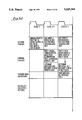
- FIG. 1 is a block diagram of a multiprocessor network architecture
- FIG. 2 is a block diagram of the architecture for the cache memory and bus interface unit for each processor
- FIGS. 3A, 3B and 3C are schematic drawings illustrating the organization of the cache memory showing the cache data array, tag array, and PV array;
- FIGS. 5A, 5B are timing charts illustrating the Command Transmit-Receive Sequence
- FIG. 6 is a list of the cache-to-bus interface unit commands
- FIG. 7 is a list of the bus interface unit-cache commands
- FIGS. 8A and 8B are flow charts illustrating the sequence of activities on the bus response lines
- FIG. 9 is a table indicating how commands are accepted depending on the collective bus response
- FIGS. 10 and 11 are schematic drawings showing the state changes in the cache PV array and the image PV array
- FIGS. 12A and 12B are examples used to illustrate data transfers (copy) and the non-atomicity of directory updates.
- FIGS. 13A and 13B are examples used to illustrate data transfers (master) and the non-atomicity of directory updates
- FIGS. 14A and 14B are examples used to illustrate cache-cache data transfer (Master) and the directory updates;
- FIGS. 15A and 15B are examples used to illustrate cache-cache data transfer (copy) and the directory updates
- FIG. 1 shows a multiprocessor network having a series of processor element modules (PE modules) 6a, 6b, 6c, 6d which are connected to a system bus 24. Also connected to the system bus 24 is a group of memory modules (MM's) 20a, 20b, and 20c.
- PE modules processor element modules
- MM's memory modules
- Each PE module, 6a, 6b, 6c, 6d has processing element (PE) shown as 10a, 10b, 10c, 10d, a private cache memory unit shown as 12a, 12b, 12c, 12d, and a bus interface unit (BIU) shown as 14a, 14b, 14c, and 14d.
- PE processing element
- BIU bus interface unit
- Each PE is linked to its cache memory unit (also called a private cache) which, in turn, is connected to a BIU which links the module to the system bus 24.
- Each memory module (20a, 20b, 20c) consists of an input queue shown as 20aiq, 20biq, 20ciq, an output queue shown as 20aoq, 20boq, 20coq, and a main memory unit designated 20am, 20bm, 20cm.
- the input queue queues up accesses (request commands) to the main memory unit.
- the main memory unit responds to each access by placing a return command in the corresponding output queue.
- the return command is a system bus command used to transfer information back to the requesting module in response to a request command.
- the input queue receives commands from the system bus and output queue transmits commands onto the system bus.
- system consists of processing elements with private caches, queueing memory modules and a system bus which interconnects all processor and memory modules.
- system bus is a backplane bus operated in a synchronous manner.
- the signals which use the system bus are described hereinafter under the heading "System Bus Signals”.
- FIG. 2 shows in detail the components of the cache and bus interface unit (BIU) and how they are interconnected.
- BIU cache and bus interface unit
- the command bus 7b is used by the processor 10 in order to transmit commands to the cache controller 8. These commands are typically Read, Write, etc.
- the address bus designated 7c is driven by the processor 10, or by the the cache controller 8, or by the BIU 28.
- the address bus 7c carries the address of a particular data word or specific status information. Arbitration as to who shall have access to the address bus 7c is controlled by the cache controller 8.
- the data bus 7d is used to connect the processor 10 and the cache data array unit 12da.
- the cache data array unit 12da is also connected to the BIU Data device 34 by means of data bus 7d. Data is transferred from the cache 12da to the BIU Data device 34 via the data bus 7d, and from the BIU Data device 34 to main memory 20, or to BIU's on other modules, over the system bus 24.
- the cache memory data array 12da is a memory which is used to store data from the memory module 20 for subsequent use by the processor 10.
- the detailed architecture of the cache memory data array 12da is shown in FIG. 3A.
- the cache memory tag array 12ta Connected to the cache controller 8 and to the address bus 7c is the cache memory tag array 12ta FIG. 3B. Since a portion of the address of a data block is designated as the "tag", this portion designated as the tag is stored in the cache memory tag array 12ta. Thus for every data block stored in the cache memory data array 12da, the cache memory tag array 12ta will store its own associative tag.
- the cache memory tag array 12ta is part of the cache directory 32cd which also includes the cache memory PV array 12pv.
- the cache memory tag array 12ta as part of the cache directory is used to find out whether a particular data block resides in the cache memory data array 12da.
- the cache memory PV array 12pv is also part of the cache directory 32cd.
- the cache PV array 12pv stores the "status" of each cache data block that resides in the cache data array 12da.
- Each data block in the cache data array 12da will be found to be in one of four states; invalid, copy, master, pending. These states are illustrated in FIG. 10.
- the cache directory 32cd is made up of the cache tag array 12ta together with the cache PV array 12pv.
- the data bus between the cache data array 12da and the BIU 34 is shown as bus 7d.
- the bus designated 15b is the command bus for transmitting commands between the cache controller 8 and the BIU 28.
- the commands transferred on this command bus 15b are listed in the tables in FIGS. 6 and 7.
- the BIU bus interface unit
- the BIU-Data Chip 34 and the BIU address and control chip 28 (BIU-AC).
- the BIU-AC 28 controls the BIU-Data 34, by means of the control bus 32a.
- the main functions of the BIU are to "snoop" on the system bus 24 to maintain coherent data and also buffer data, such data going from the cache memory 12da to the system bus 24, and reversely from the system bus 24 to the cache memory data array 12da.
- the BIU-AC 28 receives commands from the cache controller 8 and transmits them on the system bus 24. Likewise, any commands arriving from the system bus 24, which are relevant to the particular module, are received by the BIU-AC and then passed on to the cache controller 8.
- the BIU-AC 28 implements the bus protocol which guarantees coherent data in the cache. To maintain data coherency the BIU-AC 28 needs to know the state of all data held in the cache. It does so by means of the image directory 32ti.
- the image directory is an exact copy of the cache directory 32cd, and consists of the image tag array 32ta and the image PV array 32p.
- FIGS 4A and 4B show the organization of the image directory in detail.
- the signals which connect the cache directory 32cd to the cache controller 8 are as follows:
- the TAG address bits [31:12] are stored in the tag array 12ta, FIG. 3B.
- the PV status bits are stored in the PV array 12pv, FIG. 3C.
- Data is stored in the cache data array 12da, FIG. 3A. All three arrays are addressed by the ten address bits ADDR[11:2] obtained from address bus 7c.
- the ten address bits define 1k sets, where each set consists of four blocks.
- the BLOCK SELECT lines select one block in any set for writing.
- the READ/WRITE line selects a read or write operation on the arrays.
- the TAGMATCH lines (FIGS. 3B, 4B) indicate whether, and in which block, the address exists, while the PV status lines indicate the status of the desired block in the set.
- the signals which connect the image directory 32ti to the BIU-AC 28 are as follows.
- the TAG address bits [31:12]
- the PV status bits are stored in the PV array 32p. Both arrays are addressed by the ten address bits ADDR[11:2] obtained from the system bus.
- the ten address bits define 1k sets, where each set consists of four blocks.
- the BLOCK SELECT lines select one block in any set for writing.
- the READ/WRITE line selects a read or write operation on the arrays.
- the TAGMATCH lines indicate whether, and in which block, the address exists, while the PV status lines indicate the status of the desired block in the set.
- the image directory provides a means of maintaining data coherency without accessing the cache directory 32cd.
- updates to the image directory are done separately and non-atomically from the cache directory. This feature allows the PE (10) to access the cache as fast and as frequently as desired since the snooping activity is now done by the BIU using the image directory.
- This flow chart defines how the bus response lines are asserted based on the system bus command and image status.
- This table shows how commands are accepted based on the collective bus response.
- Information is transferred from one module to another by means of the system bus.
- the information relevant here is memory data.
- Other information, time-of-day, SPES (Signal Processor Element Set), are necessary for overall system operation but have no coherency implications.
- Data DAT[51:0] Fifty-two data lines are used to transfer one data word per clock.
- Command COM[5:0] The command lines define the type of bus transaction and are defined in Paragraph A-3.
- Bus Request REQ[19:0] Each module uses a unique Request line by which it signals to all other modules its intention of using the system bus (i.e. bus request). In this particular implementation the system can have up to twenty modules.
- PE-ACK This signal is used by any PE module to acknowledge receiving a bus transmission correctly. If the transmission received was a request command (i.e. a command which is a request for data), then a PE which finds (by reading its image directory) that it has the data will assert PE-ACK. Thus PE-ACK tells the transmitter that its request for data will be honored. It also tells the memory modules that they must ignore the command.
- a request command i.e. a command which is a request for data
- PE-ACK tells the transmitter that its request for data will be honored. It also tells the memory modules that they must ignore the command.
- the receiving module asserts PE-ACK, to inform the transmitter that the data was received correctly.
- PE-BUSY is used by a receiving PE module to signal the transmitter module that it cannot handle the transmission due to a full input queue. The transmitter will then retransmit later. PE-BUSY also informs the memory modules to ignore the command. PE-BUSY may be asserted by many PE modules at once.
- MM-ACK Memory modules acknowledge a transmission received without error by asserting MM-ACK. Only one memory module may assert MM-ACK at a given time.
- MM-BUSY If a command is received by a memory module which finds its input queue full then it asserts MM-BUSY. The transmitter will retransmit that command later.
- BUS-ERROR Any module which finds an error in a transmission on the system bus, signals the fact by asserting BUS-ERROR. The transmitter will retransmit later.
- PARITY SIGNALS Address, data, command and source/destination ID signals are protected by parity signals. Parity is checked by all modules on every transmission.
- the system bus specified in Paragraph A-1 is used to transfer different types of information.
- the type of information is defined by the command on the bus command lines. This section specifies all the commands which transfer memory data from MM to PE, PE to PE, and PE to MM. Other commands, which have nothing to do with coherency operations, are also defined because they are essential for system operation. Coherency operations caused by these commands are described in Paragraph B.
- No Operation When no module is transmitting, the command lines have a logic value of 111111 (binary) due to the open-collector nature of the system bus. Modules read the system bus (i.e., all the lines specified in Paragraph A-1) on every clock. When a module reads the command lines and finds a NOP it knows that there is no transmission.
- SR Shared Read
- the command originates when a PE reads the data word at some address, say C0C00001 (Hexadecimal) for example, and the cache controller reads its directory (see FIGS. 2 and 3) and finds that none of the tags in set 1 matches the tag of the processor address C0C000. Then the cache controller issues a SR command with the specific address C0C00001 to the BIU which transmits the command on the system bus. The BIU transmits the command (000001), the address (C0C00001) and the specific ID of the module for one clock period.
- the memory module which has the address C0C00001 will then send a "copy" of the data block back to the requestor (i.e. the module that issued the SR).
- PR is identified by the logic value 000010 (binary) on the command lines.
- the command originates when a PE writes at a specific address, say C0C00001 for example, and the cache controller finds that it does not have that address in its directory. Therefore, the cache controller issues a PR command to the BIU with the address specified as C0C00001. Then the BIU transmits the command (000010), the address (C0C00001), and the ID of the module on the system bus.
- the memory, or PE module which finds the data as a "master”, will return the data to the requestor designated as a master.
- a block of data is classified as "master” when it can be modified by the processor element (PE) which has that master block of data in its cache.
- TBS Transmit Block Shared
- a memory module When a memory module receives a SR command, with address C0C00001 for example, it will send back to the requestor a copy of the data block using a TBS command.
- the data block consists of the four words at addresses C0C00000, C0C00001, C0C00002 and C0C00003. Since there are four data words the transmission takes four clock cycles. In the first clock the command (010001), the address (C0C001) and the corresponding data word, and the requestors ID are transmitted. On the second, third and fourth clocks, only the data words corresponding to addresses C0C00001, C0C00002 and C0C00003 are transmitted.
- TBP Transmit Block Private
- a Purge command is used by a PE module when it returns a block of data, designated as a master, back to memory.
- the command originates at the cache controller, when the PE does a read or write and none of the four blocks in the particular set match the address required by the processor.
- the cache controller issues a SR or PR command to get the block of data.
- the cache controller also determines where in the particular set the requested data is to be placed. If that location already has a valid master, it must be returned back to memory using a Purge command. Note that a master cannot be overwritten like a copy can be.
- a Purge command takes four clocks on the system bus.
- the address In the first clock the address, the command (000110), the ID of the transmitting module and the word corresponding to the address are transmitted. In the second, third and fourth clocks the other data words are transmitted just as in a TBP or TBS command.
- a Purge command is received by the memory module which contains the specified address.
- ND New Data Write
- ND is identified by the logic value 000111 on the command lines. This command provides the capability for PE modules doing I/O functions to overwrite a block in memory, for example when a file is being read from a peripheral device. The command causes the existing master to be overwritten by the new data. If the ND is received by a PE, then the cache controller executes the overwrite, else it is done by the memory module when the master is in memory.
- the ND command consists of four words and is transmitted like a TBP.
- Time-of-Day-Read A Processor Element (PE) reads the time of day from the memory module which contains the time-of-day clock by issuing a TODR.
- PE Processor Element
- Time-of-Day-Write A PE may change the time-of-day clock in the memory module by issuing TODW.
- Time-of-Day A memory module returns the time of day, in response to a TODR by transmitting a TOD command.
- SPES Signal PE Set
- SPESACK SPES Acknowledge
- a Result command may be sent as a response to any command to report status or errors.
- This section describes how the system bus commands are transmitted and received, the role of the bus response lines, and how the "snooping function" uses the image directory. Events are described on a clock-by-clock basis using FIG. 5 which illustrates the entire sequence.
- the sequence of actions taken by the transmitter, and by all other receivers are the same for all one-clock commands.
- the sequence begins in clock A (FIG. 5A) when the transmitter module drives a command on the system bus 24.
- clock A+1 all modules 6a, 6b, 6c, 20a, 20b, 20c evaluate the command. Evaluation consists of decoding the command lines to find out what the command means, checking parity (on address, data, source/destination ID and command) and executing the snooping function.
- “Snooping” is the process of using the address specified in the bus command to access the image directory to find whether a matching address exists in the image and, if so, what the status of the data (master, copy, invalid, pending) is.
- the results of the snoop is relevant only if the command is a SR, PR, ND, Purge, TBS or TBP, as defined in Paragraph A-2 above.
- the purpose of snooping is to make the appropriate response on the PE-ACK, PE-BUSY or BUS-ERROR lines.
- the response depends on the type of command received (in Clock A for example) and on the image status for that address.
- the criteria for driving each response line are outlined next.
- PE-ACK Asserting PE-ACK in Clock A+2: If command received is SR, PR or ND, and the image state is Master, then PE-ACK is asserted by a PE module (FIG. 5) provided its input queue is not full. If a TBS, TBP (or Result, TOD or SPESACK) is received and the destination ID of the transmission matches the ID of the PE and, the state in the image is "pending" then PE-ACK is asserted. PE-ACK is asserted by only one PE module.
- PE-BUSY is asserted when the input queue is full. PE-BUSY is also asserted when an ND command is received, the image state is "copy", and the input queue is full.
- MM-ACK or MM-BUSY in Clock A+2 A memory module which contains the address specified in a SR, PR, ND or Purge command will assert MM-ACK if its input queue is not full. If the input queue is full then MM-BUSY will be asserted.
- each receiver determines for itself whether the command has to be processed. All commands except SPES are meant to be processed by one receiver only. Therefore, for four-clock commands only one receiver is actively receiving the data words in clocks A+1, A+2, A+3.
- the active receiver uses PE-ACK or MM-ACK (depending on whether the module is a PE or MM) to signal the transmitter whether the data parity was correct. If incorrect parity is found then BUS-ERROR is asserted.
- the active receiver drives its bus response (FIGS. 5A, 5B) for each data word in clocks A+2 (for data word A), A+3 (for data word B), A+4 (for data word C) and A+5 (for data word D).
- the Collective Response The purpose of driving the individual response (in clock A+2) after a command is received (in clock A+1) is to determine the collective bus response.
- the collective bus response is determined based on the individual bus response driven by each module.
- a command is accepted by the receiver, and considered to be successfully transmitted by the transmitter, only when the collective response is an acknowledge.
- FIG. 9 specifies for each command how the bus response lines are interpreted.
- the collective response (FIG. 9) guarantees that a command is acknowledged only when all modules agree (by transmitting their individual bus responses on the bus response lines) that a command is error-free.
- This section describes what the coherency rules are, and what actions are taken by the bus protocol to guarantee data coherency. Examples are used to illustrate the various coherency related actions for each command.
- the bus protocol implements the following rules to guarantee data coherency, i.e., a PE reading any specific address will always find the current value which is the value of the master block. Thus any copies made must have the same value and only one master can exist for each address.
- master blocks reside in main memory.
- PE's may have copies (in their caches) of a given master block located in main memory 20.
- a ND command causes that copy to be invalidated.
- PE-ACK When a PE has the master block for a given address it must respond with PE-ACK (unless it has an error) for SR, PR and ND commands which are transmitted on the system bus. It must also take appropriate action depending on the type of command to be described hereinafter.
- FIGS. 10 and 11 represent the four states of any data block (at a given address) which may reside in the cache data array 12da. Coherency actions taken by the cache controller 8 or BIU (34, 28) change the status of a data block.
- the "status" of a data block in cache (12da, FIGS. 2, 3A) may change due to PE accesses or BIU commands. Coherency actions caused by each command are detailed next hereunder.
- SR issued by cache controller due to PE read When a PE reads a data word and the state in cache is "invalid" (FIGS. 10, 14B) the cache controller 8 issues a Shared Read Command SR (also called a local SR because it was issued by the local PE) to the BIU 28.
- the "status" in cache directory 32cd corresponding to the address requested by the PE, is marked “Pending”.
- the marking process consists of writing the tag (for example, if address is FFF00005, then tag is FFF00) into the cache tag array 12ta and writing the PV array 12pv with binary "10" which represents the Pending state.
- This coherency action is represented in FIG. 10 by the arrow from Invalid to Pending, a status change caused by a local SR (labelled beside the arrow).
- Purge Command issued by cache controller due to local SR or PR If the cache controller 8 finds that it needs to remove a master block in cache 12da, to create space for a block that needs to be marked as Pending, it issues a Purge command. A Purge returns a master block from cache to memory 20.
- FIG. 10 represents such an action by the arrow from Valid Master (binary 11) to Invalid (binary 00). The Invalid location in the directory 32cd is now used to accommodate the incoming TBS or TBP and is marked Pending.
- An external SR is an SR (Shared Read) command that comes to the cache controller 8 from the BIU 28 which received the SR from the system bus 24.
- Such a command, which comes into the cache controller from the system bus via the BIU, is called an external (or remote) command, because it originated in some other PE 10 (as 10a, 10b, 10c, or 10d)
- An external SR causes the cache controller 8 to return the master block to memory 20, and mark its directory 32cd as Invalid (see arrow in FIG. 10 labelled "Purge due to external SR").
- TBP Transmit Block Private Command
- An external PR received by the cache controller 8 will cause it to transfer the master block 32cd by issuing a TBP command and marking the cache directory as Invalid (see arrow in FIG. 10 labelled "TBP due to external PR").
- the BIU 28 will direct the cache controller 8 to invalidate a specific copy if it determines that a valid copy exists in the cache 12da while another module 6 (6a, 6b, 6c, 6d), 20 (20a, 20b, 20c), is receiving the corresponding master block. Such an invalidation is facilitated by the INVCOPY command issued by the BIU to the cache controller.
- An INVCOPY command is also generated when a New Data ND command is detected and a valid copy exists in cache.
- TBP Transmit Block Private Command
- TBS Transmit Block Share Command
- the cache controller 8 expects to receive TBS or TBP from the BIU 28 in response to a prior issue of SR or PR to the BIU.
- TBP or TBS command When data is transferred to the cache controller 8 from the BIU 28 via a TBP or TBS command, the status of the block in cache 12da is updated from Pending to Valid Copy (for TBS), or from Pending to Valid Master (for TBP) as seen in FIG. 10.
- the coherency actions taken by the BIU 28 are based on its snooping function.
- the BIU performs the following functions when a command is received from the bus 24.
- Any BIU can identify "local" commands from “external” ones (issued by other modules) by simply comparing the source ID field of the system bus to its own ID value.
- the BIU marks its directory as Pending.
- the transition arrows correspond in FIGS. 10 and 11, and each arrow is denoted with a (1) or (2).
- a (1) denotes that this particular state change occurs before its counterpart in the other diagram.
- a (2) denotes that this state change occurs after its counterpart in the other diagram.
- a state change associated with a local SR or PR occurs first in the cache directory 32cd and afterwards in the image directory 32ti.
- the (1) or (2) denotes the natural flow of the command and therefore the sequence of updates as well. This illustrates how the two directories are updated at different times (i.e. non-atomically) in the same PE module 6.
- the BIU marks its image directory 32ti "invalid" when a master leaves the module by way of a TBP command or Purge command issued by the local cache controller 8.
- the arrow from Valid Master to Invalid in FIGS. 10 and 11 depicts the sequence--first the cache controller 8 marks its cache directory 32cd and later, when the command, is on the system bus, the image directory 32ti marked by the BIU 28.
- INVCOPY command due to external TBP or ND If the BIU detects a TBP or ND on the system bus, and also finds a valid copy status in the image directory for the same address, it updates the image directory to change the "valid copy" status to "invalid” and also issues an INVCOPY command to the cache controller 8 which does the same to cache directory 32cd. This ensures coherency rule #3.
- the sequence numbers show that the image directory 32ti in FIG. 11 does this update before the cache directory 32cd in FIG. 10.
- Incoming TBS or TB Commands Data required by the local cache controller 8 of a given PE module will be transmitted on the system bus 24 as a TBS (Transmit Block Shared) or TBP (Transmit Block Private) command.
- the BIU 28 of the requesting module will update its image directory as shown in FIG. 11 and then forward the command to the cache controller 8 which marks its own cache directory 32cd.
- the incoming TBS goes from Pending to Valid Copy Status while incoming TBP goes from Pending to Valid Master.
- External SR, PR, ND commands If the BIU detects a SR, PR, ND on the system bus and also finds the corresponding "Valid Master" status in its image directory it asserts PE-ACK, as outlined in Paragraph B. Then the BIU passes the command to the cache controller 8 which takes appropriate action depending on the command.
- the cache controller executes a Purge.
- a Purge performs two functions; it returns the master data block to memory, and also allows the module which issued the SR to make a copy while the Purge is on the system bus 24.
- the cache controller executes a TBP, and for an ND the cache controller updates the existing master with the new value and sends back a Result command to the module which issued the ND.
- FIGS. 12A and B, 13A and B, 14A and B, and 15A and B Four examples are shown in FIGS. 12A and B, 13A and B, 14A and B, and 15A and B to illustrate a complete sequence of directory updates.
- the examples show how coherency is maintained by using duplicated directories (image and cache) which are updated at different times (i.e. non-atomically).
- the PE's 10 are provided with coherent data. Since the cache directory is "decoupled" from the image directory, the PE-cache speed can be maximized.
- FIGS. 12A, 13A, 14A, and 15A two PE modules P1 and P2, and a memory module MM 20 are shown connected to the system bus 24 which may have other modules as well.
- Events are defined as actions occurring in a clock period.
- Clock periods (FIGS. 12B, 13B, 14B, 15B) are identified by t0, t1, t2, etc., where t1 is one or more clocks after t0, t2 is one or more clocks after t1 and so on.
- FIGS. 12A, 12B show a system where a master data block, at address FFF00005 for example, is in a MM and no copies exist.
- PE1 reads the value at FFF00005 and the cache controller finds that the location is invalid.
- the cache controller writes a Pending status in the cache directory.
- FIG. 12B illustrates the important events that occur in t2, t3, t4, t5, t6 and t7.
- the cache controller receives the data block and passes the requested data word to PE1 and also updates its directory to show Copy status. Note that the updates are done in t6 and t8, i.e. non-atomically.
- the state of the cache directory is shown in FIGS. 3A and 3B.
- FIGS. 13A, 13B show a subsequent event in the same system where P1 has a copy of the data in cache, at address FFF00005 for example.
- PE2 writes at address FFF00005 and the cache controller of P2 finds that it has a status of Invalid for FFF00005.
- the cache controller of P2 updates its directory to Pending and in t2 issues a PR to the BIU of P2.
- the MM returns the master block, and in t6 all BIUs check their image directories. Both images are updated simultaneously, i.e. atomically.
- the BIU of P1 finds a copy of the same block in its directory which it invalidates.
- the BIU forwards an INVCOPY command to P1 cache controller.
- FIGS. 14A, 14B show the transfer of a master block, for example, at address FFF00005, from P2 to P1. MM does not get involved because, in t4, P1 checks its image directory, finds the corresponding master and asserts PE-ACK. Thus MM knows that it must ignore this PR command.
- FIGS. 15A, 15B show the case where a master block in P1 is returned to memory via a Purge command, caused by a SR command issued by P2.
- Atomic Events are termed atomic when they occur simultaneously, or one after the other "without interruption".
- Bus Protocol A set of rules and command functions that determine data transfer and data coherency across the multiprocessor system.
- a data block is defined as a set of four words whose addresses differ only in the least two address bits (A0,A1).
- Copy A block of data classified as a copy allows the PE containing that copy to read any word in the block. No writes are permitted. Copies are made from the master primarily by MM's.
- Copy-back Cache A copy-back cache allows PE writes to be copied back to memory sometime after the write is done, rather than immediately.
- Directory A look-up table which shows the existence and status of a data block, i.e. cache directory, image directory.
- Image Array Also called image directory, is an exact copy of the cache directory, but subject to time lag.
- Invalid Designates that the data does not exist in cache memory.
- a block of data when classified as a master gives the PE containing that master in its cache the right to modify it.
- MM Main memory module.
- Non-Atomic Two events are non-atomic if other events can occur between them. See Atomic.
- PE Processor Element.
- Pending Designates that a location in cache memory is reserved for a requested block of data.
- Request Command A system bus command which is used to obtain (request) information such as memory data.
- a system bus command which is used to transfer information, such as memory data, back to the requesting module in response to a request command.
- Snooping The process of using the address specified in the bus command to read the image directory to find out whether a matching address exists in the image, and if so, what the status of the block is.
- each processor has its own private cache means and bus interface means which connect to a common system bus to permit intercommunication between the processors and a main memory means.
- Each processor has its own cache directory and image directory which duplicate each other non-atomically so that the image directory can provide information as to the availability and status of requested data blocks while leaving the cache directory uninhibited for immediate access by a requesting processor, thus providing rapid data access from cache to the requesting processor without unnecessary delays.
Abstract
Description
Claims (11)
Priority Applications (4)
| Application Number | Priority Date | Filing Date | Title |
|---|---|---|---|
| US07/270,324 US5025365A (en) | 1988-11-14 | 1988-11-14 | Hardware implemented cache coherency protocol with duplicated distributed directories for high-performance multiprocessors |
| JP1511604A JPH03502382A (en) | 1988-11-14 | 1989-10-30 | Hardware-integrated cache consistency protocol with dual distributed directories for high-performance multiprocessors |
| EP89912589A EP0435959A1 (en) | 1988-11-14 | 1989-10-30 | Hardware implemented cache coherency protocole with duplicated distributed directories for high-performance multiprocessors |
| PCT/US1989/004792 WO1990005953A1 (en) | 1988-11-14 | 1989-10-30 | Hardware implemented cache coherency protocole with duplicated distributed directories for high-performance multiprocessors |
Applications Claiming Priority (1)
| Application Number | Priority Date | Filing Date | Title |
|---|---|---|---|
| US07/270,324 US5025365A (en) | 1988-11-14 | 1988-11-14 | Hardware implemented cache coherency protocol with duplicated distributed directories for high-performance multiprocessors |
Publications (1)
| Publication Number | Publication Date |
|---|---|
| US5025365A true US5025365A (en) | 1991-06-18 |
Family
ID=23030863
Family Applications (1)
| Application Number | Title | Priority Date | Filing Date |
|---|---|---|---|
| US07/270,324 Expired - Lifetime US5025365A (en) | 1988-11-14 | 1988-11-14 | Hardware implemented cache coherency protocol with duplicated distributed directories for high-performance multiprocessors |
Country Status (4)
| Country | Link |
|---|---|
| US (1) | US5025365A (en) |
| EP (1) | EP0435959A1 (en) |
| JP (1) | JPH03502382A (en) |
| WO (1) | WO1990005953A1 (en) |
Cited By (108)
| Publication number | Priority date | Publication date | Assignee | Title |
|---|---|---|---|---|
| US5119485A (en) * | 1989-05-15 | 1992-06-02 | Motorola, Inc. | Method for data bus snooping in a data processing system by selective concurrent read and invalidate cache operation |
| US5140681A (en) * | 1988-05-25 | 1992-08-18 | Hitachi, Ltd. | Multi-processing system and cache apparatus for use in the same |
| US5193163A (en) * | 1990-10-01 | 1993-03-09 | Digital Equipment Corporation | Two-level protocol for multi-component bus ownership, and implementation in a multi-processor cache write back protocol |
| US5197146A (en) * | 1989-06-21 | 1993-03-23 | Hewlett-Packard Company | Method for maintaining cache coherence in a multiprocessor computer system |
| US5210848A (en) * | 1989-02-22 | 1993-05-11 | International Business Machines Corporation | Multi-processor caches with large granularity exclusivity locking |
| US5226144A (en) * | 1989-01-13 | 1993-07-06 | International Business Machines Corporation | Cache controller for maintaining cache coherency in a multiprocessor system including multiple data coherency procedures |
| US5228136A (en) * | 1990-01-16 | 1993-07-13 | International Business Machines Corporation | Method and apparatus to maintain cache coherency in a multiprocessor system with each processor's private cache updating or invalidating its contents based upon set activity |
| US5230070A (en) * | 1989-09-08 | 1993-07-20 | International Business Machines Corporation | Access authorization table for multi-processor caches |
| US5247649A (en) * | 1988-05-06 | 1993-09-21 | Hitachi, Ltd. | Multi-processor system having a multi-port cache memory |
| US5249283A (en) * | 1990-12-24 | 1993-09-28 | Ncr Corporation | Cache coherency method and apparatus for a multiple path interconnection network |
| US5265235A (en) * | 1990-11-30 | 1993-11-23 | Xerox Corporation | Consistency protocols for shared memory multiprocessors |
| US5274787A (en) * | 1990-01-19 | 1993-12-28 | Nippon Telegraph & Telephone Corp. | Method of copy-back cache coherence control and tightly coupled multi-processor system with split transfer system bus |
| US5276828A (en) * | 1989-03-01 | 1994-01-04 | Digital Equipment Corporation | Methods of maintaining cache coherence and processor synchronization in a multiprocessor system using send and receive instructions |
| US5276852A (en) * | 1990-10-01 | 1994-01-04 | Digital Equipment Corporation | Method and apparatus for controlling a processor bus used by multiple processor components during writeback cache transactions |
| US5317720A (en) * | 1990-06-29 | 1994-05-31 | Digital Equipment Corporation | Processor system with writeback cache using writeback and non writeback transactions stored in separate queues |
| US5319766A (en) * | 1992-04-24 | 1994-06-07 | Digital Equipment Corporation | Duplicate tag store for a processor having primary and backup cache memories in a multiprocessor computer system |
| US5337273A (en) * | 1993-07-30 | 1994-08-09 | Sgs-Thomson Microelectronics, Inc. | Charge sharing flash clear for memory arrays |
| US5341483A (en) * | 1987-12-22 | 1994-08-23 | Kendall Square Research Corporation | Dynamic hierarchial associative memory |
| US5341487A (en) * | 1991-12-20 | 1994-08-23 | International Business Machines Corp. | Personal computer having memory system with write-through cache and pipelined snoop cycles |
| US5377345A (en) * | 1992-04-29 | 1994-12-27 | Sun Microsystems, Inc. | Methods and apparatus for providing multiple pending operations in a cache consistent multiple processor computer system |
| US5404489A (en) * | 1991-02-13 | 1995-04-04 | Hewlett-Packard Company | System and method for minimizing cache interruptions by inhibiting snoop cycles if access is to an exclusive page |
| US5426765A (en) * | 1991-08-30 | 1995-06-20 | Compaq Computer Corporation | Multiprocessor cache abitration |
| US5446856A (en) * | 1991-04-29 | 1995-08-29 | Intel Corporation | Circuitry and method for addressing global array elements in a distributed memory, multiple processor computer |
| US5454082A (en) * | 1991-09-18 | 1995-09-26 | Ncr Corporation | System for preventing an unselected controller from transferring data via a first bus while concurrently permitting it to transfer data via a second bus |
| US5455925A (en) * | 1989-09-19 | 1995-10-03 | Fujitsu Limited | Data processing device for maintaining coherency of data stored in main memory, external cache memory and internal cache memory |
| US5497472A (en) * | 1989-12-13 | 1996-03-05 | Hitachi, Ltd. | Cache control method and apparatus for storing data in a cache memory and for indicating completion of a write request irrespective of whether a record to be accessed exists in an external storage unit |
| US5506967A (en) * | 1993-06-15 | 1996-04-09 | Unisys Corporation | Storage queue with adjustable level thresholds for cache invalidation systems in cache oriented computer architectures |
| US5511164A (en) * | 1995-03-01 | 1996-04-23 | Unisys Corporation | Method and apparatus for determining the source and nature of an error within a computer system |
| US5515522A (en) * | 1994-02-24 | 1996-05-07 | Hewlett-Packard Company | Coherence index generation for use by an input/output adapter located outside of the processor to detect whether the updated version of data resides within the cache |
| US5526512A (en) * | 1993-09-20 | 1996-06-11 | International Business Machines Corporation | Dynamic management of snoop granularity for a coherent asynchronous DMA cache |
| US5530835A (en) * | 1991-09-18 | 1996-06-25 | Ncr Corporation | Computer memory data merging technique for computers with write-back caches |
| US5535393A (en) * | 1991-09-20 | 1996-07-09 | Reeve; Christopher L. | System for parallel processing that compiles a filed sequence of instructions within an iteration space |
| US5537569A (en) * | 1993-03-02 | 1996-07-16 | Kabushiki Kaisha Toshiba | Multiprocessor system utilizing a directory memory and including grouped processing elements each having cache |
| US5603005A (en) * | 1994-12-27 | 1997-02-11 | Unisys Corporation | Cache coherency scheme for XBAR storage structure with delayed invalidates until associated write request is executed |
| US5604882A (en) * | 1993-08-27 | 1997-02-18 | International Business Machines Corporation | System and method for empty notification from peer cache units to global storage control unit in a multiprocessor data processing system |
| US5604865A (en) * | 1991-07-08 | 1997-02-18 | Seiko Epson Corporation | Microprocessor architecture with a switch network for data transfer between cache, memory port, and IOU |
| US5611070A (en) * | 1990-05-10 | 1997-03-11 | Heidelberger; Philip | Methods and apparatus for performing a write/load cache protocol |
| US5617556A (en) * | 1993-09-20 | 1997-04-01 | International Business Machines Corporation | System and method to prevent the occurrence of a snoop push during read and write operations |
| US5630095A (en) * | 1993-08-03 | 1997-05-13 | Motorola Inc. | Method for use with a data coherency protocol allowing multiple snoop queries to a single snoop transaction and system therefor |
| US5659710A (en) * | 1995-11-29 | 1997-08-19 | International Business Machines Corporation | Cache coherency method and system employing serially encoded snoop responses |
| US5684976A (en) * | 1994-11-16 | 1997-11-04 | International Business Machines Corporation | Method and system for reduced address tags storage within a directory having a tree-like data structure |
| US5701313A (en) * | 1995-02-24 | 1997-12-23 | Unisys Corporation | Method and apparatus for removing soft errors from a memory |
| US5717942A (en) * | 1994-12-27 | 1998-02-10 | Unisys Corporation | Reset for independent partitions within a computer system |
| US5724533A (en) * | 1995-11-17 | 1998-03-03 | Unisys Corporation | High performance instruction data path |
| US5726895A (en) * | 1993-04-28 | 1998-03-10 | Fanuc Ltd. | Combined two computer system |
| US5737568A (en) * | 1990-07-09 | 1998-04-07 | Canon Kabushiki Kaisha | Method and apparatus to control cache memory in multiprocessor system utilizing a shared memory |
| US5761413A (en) * | 1987-12-22 | 1998-06-02 | Sun Microsystems, Inc. | Fault containment system for multiprocessor with shared memory |
| US5778437A (en) * | 1995-09-25 | 1998-07-07 | International Business Machines Corporation | Invalidation bus optimization for multiprocessors using directory-based cache coherence protocols in which an address of a line to be modified is placed on the invalidation bus simultaneously with sending a modify request to the directory |
| US5778429A (en) * | 1994-07-04 | 1998-07-07 | Hitachi, Ltd. | Parallel processor system including a cache memory subsystem that has independently addressable local and remote data areas |
| US5781757A (en) * | 1994-10-11 | 1998-07-14 | International Business Machines Corporation | Adaptive scalable cache coherence network for a multiprocessor data processing system |
| US5809533A (en) * | 1993-02-18 | 1998-09-15 | Unisys Corporation | Dual bus system with multiple processors having data coherency maintenance |
| US5809537A (en) * | 1995-12-08 | 1998-09-15 | International Business Machines Corp. | Method and system for simultaneous processing of snoop and cache operations |
| US5822578A (en) * | 1987-12-22 | 1998-10-13 | Sun Microsystems, Inc. | System for inserting instructions into processor instruction stream in order to perform interrupt processing |
| US5822766A (en) * | 1997-01-09 | 1998-10-13 | Unisys Corporation | Main memory interface for high speed data transfer |
| US5838946A (en) * | 1990-04-14 | 1998-11-17 | Sun Microsystems, Inc. | Method and apparatus for accomplishing processor read of selected information through a cache memory |
| US5875201A (en) * | 1996-12-30 | 1999-02-23 | Unisys Corporation | Second level cache having instruction cache parity error control |
| US5893149A (en) * | 1996-07-01 | 1999-04-06 | Sun Microsystems, Inc. | Flushing of cache memory in a computer system |
| US5923898A (en) * | 1997-05-14 | 1999-07-13 | International Business Machines Corporation | System for executing I/O request when an I/O request queue entry matches a snoop table entry or executing snoop when not matched |
| US5960458A (en) * | 1995-08-28 | 1999-09-28 | Hitachi, Ltd. | Shared memory system |
| US5960455A (en) * | 1996-12-30 | 1999-09-28 | Unisys Corporation | Scalable cross bar type storage controller |
| US5970253A (en) * | 1997-01-09 | 1999-10-19 | Unisys Corporation | Priority logic for selecting and stacking data |
| US5991819A (en) * | 1996-12-03 | 1999-11-23 | Intel Corporation | Dual-ported memory controller which maintains cache coherency using a memory line status table |
| US6012127A (en) * | 1997-12-12 | 2000-01-04 | Intel Corporation | Multiprocessor computing apparatus with optional coherency directory |
| US6021261A (en) * | 1996-12-05 | 2000-02-01 | International Business Machines Corporation | Method and system for testing a multiprocessor data processing system utilizing a plurality of event tracers |
| US6029204A (en) * | 1997-03-13 | 2000-02-22 | International Business Machines Corporation | Precise synchronization mechanism for SMP system buses using tagged snoop operations to avoid retries |
| US6049849A (en) * | 1997-04-14 | 2000-04-11 | International Business Machines Corporation | Imprecise method and system for selecting an alternative cache entry for replacement in response to a conflict between cache operation requests |
| US6049851A (en) * | 1994-02-14 | 2000-04-11 | Hewlett-Packard Company | Method and apparatus for checking cache coherency in a computer architecture |
| US6052762A (en) * | 1996-12-02 | 2000-04-18 | International Business Machines Corp. | Method and apparatus for reducing system snoop latency |
| US6088769A (en) * | 1996-10-01 | 2000-07-11 | International Business Machines Corporation | Multiprocessor cache coherence directed by combined local and global tables |
| US6088758A (en) * | 1991-09-20 | 2000-07-11 | Sun Microsystems, Inc. | Method and apparatus for distributing data in a digital data processor with distributed memory |
| US6112283A (en) * | 1998-08-06 | 2000-08-29 | Intel Corporation | Out-of-order snooping for multiprocessor computer systems |
| US6145057A (en) * | 1997-04-14 | 2000-11-07 | International Business Machines Corporation | Precise method and system for selecting an alternative cache entry for replacement in response to a conflict between cache operation requests |
| US6279098B1 (en) | 1996-12-16 | 2001-08-21 | Unisys Corporation | Method of and apparatus for serial dynamic system partitioning |
| US20010037419A1 (en) * | 1996-07-01 | 2001-11-01 | Sun Microsystems, Inc. | Multiprocessing system configured to perform efficient block copy operations |
| US6332185B1 (en) | 1991-09-20 | 2001-12-18 | Sun Microsystems, Inc. | Method and apparatus for paging data and attributes including an atomic attribute for digital data processor |
| US6351790B1 (en) * | 1998-03-23 | 2002-02-26 | Stmicroelectronics Limited | Cache coherency mechanism |
| US6374332B1 (en) * | 1999-09-30 | 2002-04-16 | Unisys Corporation | Cache control system for performing multiple outstanding ownership requests |
| US6377582B1 (en) | 1998-08-06 | 2002-04-23 | Intel Corporation | Decentralized ring arbitration for multiprocessor computer systems |
| US20020111992A1 (en) * | 2000-12-18 | 2002-08-15 | Copeland George P. | JSP composition in a cache for web applications with dynamic content |
| US20020116448A1 (en) * | 2000-12-18 | 2002-08-22 | Copeland George P. | Cofetching in a command cache |
| US20020124144A1 (en) * | 2000-06-10 | 2002-09-05 | Kourosh Gharachorloo | Scalable multiprocessor system and cache coherence method implementing store-conditional memory transactions while an associated directory entry is encoded as a coarse bit vector |
| US6457101B1 (en) * | 1999-12-20 | 2002-09-24 | Unisys Corporation | System and method for providing the speculative return of cached data within a hierarchical memory system |
| US6463506B1 (en) * | 2000-04-29 | 2002-10-08 | Hewlett-Packard Company | Arrangement of data within cache lines so that tags are first data received |
| US6502136B1 (en) * | 1994-03-24 | 2002-12-31 | Hitachi, Ltd. | Exclusive control method with each node controlling issue of an exclusive use request to a shared resource, a computer system therefor and a computer system with a circuit for detecting writing of an event flag into a shared main storage |
| US6549984B1 (en) * | 1997-12-17 | 2003-04-15 | Intel Corporation | Multi-bus access cache |
| US6574219B1 (en) | 1998-08-06 | 2003-06-03 | Intel Corp | Passive message ordering on a decentralized ring |
| US20040015969A1 (en) * | 2002-06-24 | 2004-01-22 | Chang Stephen S. | Controlling snoop activities using task table in multiprocessor system |
| US20040027875A1 (en) * | 2001-09-27 | 2004-02-12 | Clemens Dinges | Dynamic access to automation resources |
| US6694412B2 (en) | 1987-12-22 | 2004-02-17 | Sun Microsystems, Inc. | Multiprocessor digital data processing system |
| US6697925B1 (en) | 2000-12-22 | 2004-02-24 | Unisys Corporation | Use of a cache ownership mechanism to synchronize multiple dayclocks |
| US20040073630A1 (en) * | 2000-12-18 | 2004-04-15 | Copeland George P. | Integrated JSP and command cache for web applications with dynamic content |
| US6785775B1 (en) | 2002-03-19 | 2004-08-31 | Unisys Corporation | Use of a cache coherency mechanism as a doorbell indicator for input/output hardware queues |
| US6807606B2 (en) | 2000-12-18 | 2004-10-19 | International Business Machines Corp. | Distributed execution coordination for web caching with dynamic content |
| US20040267919A1 (en) * | 2003-06-30 | 2004-12-30 | International Business Machines Corporation | Method and system for providing server management peripheral caching using a shared bus |
| US6857049B1 (en) | 2000-08-30 | 2005-02-15 | Unisys Corporation | Method for managing flushes with the cache |
| US6868482B1 (en) | 1997-01-07 | 2005-03-15 | Unisys Corporation | Method and apparatus for parallel store-in second level caching |
| US6886063B1 (en) * | 1999-11-10 | 2005-04-26 | Digi International, Inc. | Systems, devices, structures, and methods to share resources among entities |
| US6928517B1 (en) | 2000-08-30 | 2005-08-09 | Unisys Corporation | Method for avoiding delays during snoop requests |
| US7069391B1 (en) | 2000-08-30 | 2006-06-27 | Unisys Corporation | Method for improved first level cache coherency |
| US20070168319A1 (en) * | 1998-02-13 | 2007-07-19 | Oracle International Corporation | Methods to perform disk writes in a distributed shared disk system needing consistency across failures |
| US20070174541A1 (en) * | 1998-02-13 | 2007-07-26 | Sashikanth Chandrasekaran | Methods to perform disk writes in a distributed shared disk system needing consistency across failures |
| US20090172297A1 (en) * | 2007-12-26 | 2009-07-02 | Nec Corporation | Cache memory system and cache memory control method |
| US7702800B2 (en) | 2000-12-18 | 2010-04-20 | International Business Machines Corporation | Detecting and handling affinity breaks in web applications |
| US20100250833A1 (en) * | 2009-03-30 | 2010-09-30 | Trika Sanjeev N | Techniques to perform power fail-safe caching without atomic metadata |
| US20110106778A1 (en) * | 2009-11-05 | 2011-05-05 | Oracle International Corporation | Lock manager on disk |
| US20110119447A1 (en) * | 2009-11-18 | 2011-05-19 | Research In Motion Limited | Method and apparatus for managing memory in a mobile electronic device |
| US20130138885A1 (en) * | 2011-11-30 | 2013-05-30 | International Business Machines Corporation | Dynamic process/object scoped memory affinity adjuster |
| CN103870395A (en) * | 2014-03-04 | 2014-06-18 | 华为技术有限公司 | Catalog maintaining method and catalog maintaining device |
Families Citing this family (10)
| Publication number | Priority date | Publication date | Assignee | Title |
|---|---|---|---|---|
| EP0591405A1 (en) * | 1991-06-20 | 1994-04-13 | Unisys Corporation | Multiprocessor array |
| EP0553742A1 (en) * | 1992-01-31 | 1993-08-04 | Motorola, Inc. | A method of operating a first and second cache tag memory array |
| US5434993A (en) * | 1992-11-09 | 1995-07-18 | Sun Microsystems, Inc. | Methods and apparatus for creating a pending write-back controller for a cache controller on a packet switched memory bus employing dual directories |
| JP2902976B2 (en) * | 1995-06-19 | 1999-06-07 | 株式会社東芝 | Cache flush device |
| JP3919224B2 (en) * | 1996-01-25 | 2007-05-23 | ユニシス・コーポレイション | Method and circuit for executing a read command and changing a data word in a multi-level distributed data processing system |
| JP2000163386A (en) * | 1998-11-25 | 2000-06-16 | Nec Software Chugoku Ltd | Decentralized shared memory system and its managing method |
| US6526480B1 (en) | 1998-12-10 | 2003-02-25 | Fujitsu Limited | Cache apparatus and control method allowing speculative processing of data |
| US11257271B2 (en) | 2013-09-26 | 2022-02-22 | Imagination Technologies Limited | Atomic memory update unit and methods |
| US9466091B2 (en) | 2013-09-26 | 2016-10-11 | Imagination Technologies Limited | Atomic memory update unit and methods |
| GB2520603B (en) * | 2013-09-26 | 2016-04-06 | Imagination Tech Ltd | Atomic memory update unit and methods |
Citations (11)
| Publication number | Priority date | Publication date | Assignee | Title |
|---|---|---|---|---|
| US3845474A (en) * | 1973-11-05 | 1974-10-29 | Honeywell Inf Systems | Cache store clearing operation for multiprocessor mode |
| US3967247A (en) * | 1974-11-11 | 1976-06-29 | Sperry Rand Corporation | Storage interface unit |
| US4056844A (en) * | 1974-02-26 | 1977-11-01 | Hitachi, Ltd. | Memory control system using plural buffer address arrays |
| US4442487A (en) * | 1981-12-31 | 1984-04-10 | International Business Machines Corporation | Three level memory hierarchy using write and share flags |
| US4490190A (en) * | 1981-03-13 | 1984-12-25 | Societe Anonyme Dite: Vide Et Traitement | Process for thermochemical treatments of metals by ionic bombardment |
| EP0165823A2 (en) * | 1984-06-22 | 1985-12-27 | Fujitsu Limited | Tag control circuit for buffer storage |
| US4755930A (en) * | 1985-06-27 | 1988-07-05 | Encore Computer Corporation | Hierarchical cache memory system and method |
| EP0278196A1 (en) * | 1986-12-31 | 1988-08-17 | Thomson-Csf | Cache management method in a multiprocessor system |
| US4843542A (en) * | 1986-11-12 | 1989-06-27 | Xerox Corporation | Virtual memory cache for use in multi-processing systems |
| US4853846A (en) * | 1986-07-29 | 1989-08-01 | Intel Corporation | Bus expander with logic for virtualizing single cache control into dual channels with separate directories and prefetch for different processors |
| US4860192A (en) * | 1985-02-22 | 1989-08-22 | Intergraph Corporation | Quadword boundary cache system |
Family Cites Families (1)
| Publication number | Priority date | Publication date | Assignee | Title |
|---|---|---|---|---|
| US4494190A (en) * | 1982-05-12 | 1985-01-15 | Honeywell Information Systems Inc. | FIFO buffer to cache memory |
-
1988
- 1988-11-14 US US07/270,324 patent/US5025365A/en not_active Expired - Lifetime
-
1989
- 1989-10-30 JP JP1511604A patent/JPH03502382A/en active Pending
- 1989-10-30 WO PCT/US1989/004792 patent/WO1990005953A1/en not_active Application Discontinuation
- 1989-10-30 EP EP89912589A patent/EP0435959A1/en not_active Withdrawn
Patent Citations (11)
| Publication number | Priority date | Publication date | Assignee | Title |
|---|---|---|---|---|
| US3845474A (en) * | 1973-11-05 | 1974-10-29 | Honeywell Inf Systems | Cache store clearing operation for multiprocessor mode |
| US4056844A (en) * | 1974-02-26 | 1977-11-01 | Hitachi, Ltd. | Memory control system using plural buffer address arrays |
| US3967247A (en) * | 1974-11-11 | 1976-06-29 | Sperry Rand Corporation | Storage interface unit |
| US4490190A (en) * | 1981-03-13 | 1984-12-25 | Societe Anonyme Dite: Vide Et Traitement | Process for thermochemical treatments of metals by ionic bombardment |
| US4442487A (en) * | 1981-12-31 | 1984-04-10 | International Business Machines Corporation | Three level memory hierarchy using write and share flags |
| EP0165823A2 (en) * | 1984-06-22 | 1985-12-27 | Fujitsu Limited | Tag control circuit for buffer storage |
| US4860192A (en) * | 1985-02-22 | 1989-08-22 | Intergraph Corporation | Quadword boundary cache system |
| US4755930A (en) * | 1985-06-27 | 1988-07-05 | Encore Computer Corporation | Hierarchical cache memory system and method |
| US4853846A (en) * | 1986-07-29 | 1989-08-01 | Intel Corporation | Bus expander with logic for virtualizing single cache control into dual channels with separate directories and prefetch for different processors |
| US4843542A (en) * | 1986-11-12 | 1989-06-27 | Xerox Corporation | Virtual memory cache for use in multi-processing systems |
| EP0278196A1 (en) * | 1986-12-31 | 1988-08-17 | Thomson-Csf | Cache management method in a multiprocessor system |
Non-Patent Citations (2)
| Title |
|---|
| Censier, "A New Solution to Coherence Problems in Multi-Cache System", 12/12/78, IEEE Transactions on Computers, vol. C-27, pp. 1112-1118. |
| Censier, A New Solution to Coherence Problems in Multi Cache System , 12/12/78, IEEE Transactions on Computers, vol. C 27, pp. 1112 1118. * |
Cited By (138)
| Publication number | Priority date | Publication date | Assignee | Title |
|---|---|---|---|---|
| US5822578A (en) * | 1987-12-22 | 1998-10-13 | Sun Microsystems, Inc. | System for inserting instructions into processor instruction stream in order to perform interrupt processing |
| US5761413A (en) * | 1987-12-22 | 1998-06-02 | Sun Microsystems, Inc. | Fault containment system for multiprocessor with shared memory |
| US6694412B2 (en) | 1987-12-22 | 2004-02-17 | Sun Microsystems, Inc. | Multiprocessor digital data processing system |
| US5341483A (en) * | 1987-12-22 | 1994-08-23 | Kendall Square Research Corporation | Dynamic hierarchial associative memory |
| US5247649A (en) * | 1988-05-06 | 1993-09-21 | Hitachi, Ltd. | Multi-processor system having a multi-port cache memory |
| US5140681A (en) * | 1988-05-25 | 1992-08-18 | Hitachi, Ltd. | Multi-processing system and cache apparatus for use in the same |
| US5226144A (en) * | 1989-01-13 | 1993-07-06 | International Business Machines Corporation | Cache controller for maintaining cache coherency in a multiprocessor system including multiple data coherency procedures |
| US5210848A (en) * | 1989-02-22 | 1993-05-11 | International Business Machines Corporation | Multi-processor caches with large granularity exclusivity locking |
| US5276828A (en) * | 1989-03-01 | 1994-01-04 | Digital Equipment Corporation | Methods of maintaining cache coherence and processor synchronization in a multiprocessor system using send and receive instructions |
| US5119485A (en) * | 1989-05-15 | 1992-06-02 | Motorola, Inc. | Method for data bus snooping in a data processing system by selective concurrent read and invalidate cache operation |
| US5197146A (en) * | 1989-06-21 | 1993-03-23 | Hewlett-Packard Company | Method for maintaining cache coherence in a multiprocessor computer system |
| US5230070A (en) * | 1989-09-08 | 1993-07-20 | International Business Machines Corporation | Access authorization table for multi-processor caches |
| US5455925A (en) * | 1989-09-19 | 1995-10-03 | Fujitsu Limited | Data processing device for maintaining coherency of data stored in main memory, external cache memory and internal cache memory |
| US20040030828A1 (en) * | 1989-12-13 | 2004-02-12 | Hitachi, Ltd. | Cache control method and apparatus |
| US5497472A (en) * | 1989-12-13 | 1996-03-05 | Hitachi, Ltd. | Cache control method and apparatus for storing data in a cache memory and for indicating completion of a write request irrespective of whether a record to be accessed exists in an external storage unit |
| US7082496B2 (en) | 1989-12-13 | 2006-07-25 | Hitachi, Ltd. | Cache control method and apparatus |
| US5694576A (en) * | 1989-12-13 | 1997-12-02 | Hitachi, Ltd. | Cache control by adding record identification information to partial write request |
| US6085286A (en) * | 1989-12-13 | 2000-07-04 | Hitachi, Ltd. | Cache control method and apparatus |
| US5228136A (en) * | 1990-01-16 | 1993-07-13 | International Business Machines Corporation | Method and apparatus to maintain cache coherency in a multiprocessor system with each processor's private cache updating or invalidating its contents based upon set activity |
| US5274787A (en) * | 1990-01-19 | 1993-12-28 | Nippon Telegraph & Telephone Corp. | Method of copy-back cache coherence control and tightly coupled multi-processor system with split transfer system bus |
| US5838946A (en) * | 1990-04-14 | 1998-11-17 | Sun Microsystems, Inc. | Method and apparatus for accomplishing processor read of selected information through a cache memory |
| US5611070A (en) * | 1990-05-10 | 1997-03-11 | Heidelberger; Philip | Methods and apparatus for performing a write/load cache protocol |
| US5317720A (en) * | 1990-06-29 | 1994-05-31 | Digital Equipment Corporation | Processor system with writeback cache using writeback and non writeback transactions stored in separate queues |
| US5737568A (en) * | 1990-07-09 | 1998-04-07 | Canon Kabushiki Kaisha | Method and apparatus to control cache memory in multiprocessor system utilizing a shared memory |
| US5276852A (en) * | 1990-10-01 | 1994-01-04 | Digital Equipment Corporation | Method and apparatus for controlling a processor bus used by multiple processor components during writeback cache transactions |
| US5193163A (en) * | 1990-10-01 | 1993-03-09 | Digital Equipment Corporation | Two-level protocol for multi-component bus ownership, and implementation in a multi-processor cache write back protocol |
| US5265235A (en) * | 1990-11-30 | 1993-11-23 | Xerox Corporation | Consistency protocols for shared memory multiprocessors |
| US5249283A (en) * | 1990-12-24 | 1993-09-28 | Ncr Corporation | Cache coherency method and apparatus for a multiple path interconnection network |
| US5404489A (en) * | 1991-02-13 | 1995-04-04 | Hewlett-Packard Company | System and method for minimizing cache interruptions by inhibiting snoop cycles if access is to an exclusive page |
| US5446856A (en) * | 1991-04-29 | 1995-08-29 | Intel Corporation | Circuitry and method for addressing global array elements in a distributed memory, multiple processor computer |
| US5604865A (en) * | 1991-07-08 | 1997-02-18 | Seiko Epson Corporation | Microprocessor architecture with a switch network for data transfer between cache, memory port, and IOU |
| US5426765A (en) * | 1991-08-30 | 1995-06-20 | Compaq Computer Corporation | Multiprocessor cache abitration |
| US5454082A (en) * | 1991-09-18 | 1995-09-26 | Ncr Corporation | System for preventing an unselected controller from transferring data via a first bus while concurrently permitting it to transfer data via a second bus |
| US5530835A (en) * | 1991-09-18 | 1996-06-25 | Ncr Corporation | Computer memory data merging technique for computers with write-back caches |
| US5535393A (en) * | 1991-09-20 | 1996-07-09 | Reeve; Christopher L. | System for parallel processing that compiles a filed sequence of instructions within an iteration space |
| US6332185B1 (en) | 1991-09-20 | 2001-12-18 | Sun Microsystems, Inc. | Method and apparatus for paging data and attributes including an atomic attribute for digital data processor |
| US6088758A (en) * | 1991-09-20 | 2000-07-11 | Sun Microsystems, Inc. | Method and apparatus for distributing data in a digital data processor with distributed memory |
| US5341487A (en) * | 1991-12-20 | 1994-08-23 | International Business Machines Corp. | Personal computer having memory system with write-through cache and pipelined snoop cycles |
| US5319766A (en) * | 1992-04-24 | 1994-06-07 | Digital Equipment Corporation | Duplicate tag store for a processor having primary and backup cache memories in a multiprocessor computer system |
| US5377345A (en) * | 1992-04-29 | 1994-12-27 | Sun Microsystems, Inc. | Methods and apparatus for providing multiple pending operations in a cache consistent multiple processor computer system |
| US5809533A (en) * | 1993-02-18 | 1998-09-15 | Unisys Corporation | Dual bus system with multiple processors having data coherency maintenance |
| US5537569A (en) * | 1993-03-02 | 1996-07-16 | Kabushiki Kaisha Toshiba | Multiprocessor system utilizing a directory memory and including grouped processing elements each having cache |
| US5726895A (en) * | 1993-04-28 | 1998-03-10 | Fanuc Ltd. | Combined two computer system |
| US5506967A (en) * | 1993-06-15 | 1996-04-09 | Unisys Corporation | Storage queue with adjustable level thresholds for cache invalidation systems in cache oriented computer architectures |
| US5337273A (en) * | 1993-07-30 | 1994-08-09 | Sgs-Thomson Microelectronics, Inc. | Charge sharing flash clear for memory arrays |
| US5630095A (en) * | 1993-08-03 | 1997-05-13 | Motorola Inc. | Method for use with a data coherency protocol allowing multiple snoop queries to a single snoop transaction and system therefor |
| US5604882A (en) * | 1993-08-27 | 1997-02-18 | International Business Machines Corporation | System and method for empty notification from peer cache units to global storage control unit in a multiprocessor data processing system |
| US5526512A (en) * | 1993-09-20 | 1996-06-11 | International Business Machines Corporation | Dynamic management of snoop granularity for a coherent asynchronous DMA cache |
| US5617556A (en) * | 1993-09-20 | 1997-04-01 | International Business Machines Corporation | System and method to prevent the occurrence of a snoop push during read and write operations |
| US6049851A (en) * | 1994-02-14 | 2000-04-11 | Hewlett-Packard Company | Method and apparatus for checking cache coherency in a computer architecture |
| US5515522A (en) * | 1994-02-24 | 1996-05-07 | Hewlett-Packard Company | Coherence index generation for use by an input/output adapter located outside of the processor to detect whether the updated version of data resides within the cache |
| US6502136B1 (en) * | 1994-03-24 | 2002-12-31 | Hitachi, Ltd. | Exclusive control method with each node controlling issue of an exclusive use request to a shared resource, a computer system therefor and a computer system with a circuit for detecting writing of an event flag into a shared main storage |
| US5778429A (en) * | 1994-07-04 | 1998-07-07 | Hitachi, Ltd. | Parallel processor system including a cache memory subsystem that has independently addressable local and remote data areas |
| US6295579B1 (en) | 1994-07-04 | 2001-09-25 | Hitachi, Ltd. | Parallel processor system including a cache memory subsystem that has independently addressable local and remote data areas |
| US5781757A (en) * | 1994-10-11 | 1998-07-14 | International Business Machines Corporation | Adaptive scalable cache coherence network for a multiprocessor data processing system |
| US5684976A (en) * | 1994-11-16 | 1997-11-04 | International Business Machines Corporation | Method and system for reduced address tags storage within a directory having a tree-like data structure |
| US5603005A (en) * | 1994-12-27 | 1997-02-11 | Unisys Corporation | Cache coherency scheme for XBAR storage structure with delayed invalidates until associated write request is executed |
| US5717942A (en) * | 1994-12-27 | 1998-02-10 | Unisys Corporation | Reset for independent partitions within a computer system |
| US5701313A (en) * | 1995-02-24 | 1997-12-23 | Unisys Corporation | Method and apparatus for removing soft errors from a memory |
| US5511164A (en) * | 1995-03-01 | 1996-04-23 | Unisys Corporation | Method and apparatus for determining the source and nature of an error within a computer system |
| US5960458A (en) * | 1995-08-28 | 1999-09-28 | Hitachi, Ltd. | Shared memory system |
| US6161168A (en) * | 1995-08-28 | 2000-12-12 | Hitachi, Ltd. | Shared memory system |
| US5778437A (en) * | 1995-09-25 | 1998-07-07 | International Business Machines Corporation | Invalidation bus optimization for multiprocessors using directory-based cache coherence protocols in which an address of a line to be modified is placed on the invalidation bus simultaneously with sending a modify request to the directory |
| US5724533A (en) * | 1995-11-17 | 1998-03-03 | Unisys Corporation | High performance instruction data path |
| US5659710A (en) * | 1995-11-29 | 1997-08-19 | International Business Machines Corporation | Cache coherency method and system employing serially encoded snoop responses |
| US5809537A (en) * | 1995-12-08 | 1998-09-15 | International Business Machines Corp. | Method and system for simultaneous processing of snoop and cache operations |
| US20010037419A1 (en) * | 1996-07-01 | 2001-11-01 | Sun Microsystems, Inc. | Multiprocessing system configured to perform efficient block copy operations |
| US5893149A (en) * | 1996-07-01 | 1999-04-06 | Sun Microsystems, Inc. | Flushing of cache memory in a computer system |
| US6760786B2 (en) * | 1996-07-01 | 2004-07-06 | Sun Microsystems, Inc. | Multiprocessing system configured to perform efficient block copy operations |
| US6088769A (en) * | 1996-10-01 | 2000-07-11 | International Business Machines Corporation | Multiprocessor cache coherence directed by combined local and global tables |
| US6052762A (en) * | 1996-12-02 | 2000-04-18 | International Business Machines Corp. | Method and apparatus for reducing system snoop latency |
| US5991819A (en) * | 1996-12-03 | 1999-11-23 | Intel Corporation | Dual-ported memory controller which maintains cache coherency using a memory line status table |
| US6021261A (en) * | 1996-12-05 | 2000-02-01 | International Business Machines Corporation | Method and system for testing a multiprocessor data processing system utilizing a plurality of event tracers |
| US6279098B1 (en) | 1996-12-16 | 2001-08-21 | Unisys Corporation | Method of and apparatus for serial dynamic system partitioning |
| US5875201A (en) * | 1996-12-30 | 1999-02-23 | Unisys Corporation | Second level cache having instruction cache parity error control |
| US5960455A (en) * | 1996-12-30 | 1999-09-28 | Unisys Corporation | Scalable cross bar type storage controller |
| US6868482B1 (en) | 1997-01-07 | 2005-03-15 | Unisys Corporation | Method and apparatus for parallel store-in second level caching |
| US5822766A (en) * | 1997-01-09 | 1998-10-13 | Unisys Corporation | Main memory interface for high speed data transfer |
| US5970253A (en) * | 1997-01-09 | 1999-10-19 | Unisys Corporation | Priority logic for selecting and stacking data |
| US6029204A (en) * | 1997-03-13 | 2000-02-22 | International Business Machines Corporation | Precise synchronization mechanism for SMP system buses using tagged snoop operations to avoid retries |
| US6049849A (en) * | 1997-04-14 | 2000-04-11 | International Business Machines Corporation | Imprecise method and system for selecting an alternative cache entry for replacement in response to a conflict between cache operation requests |
| US6145057A (en) * | 1997-04-14 | 2000-11-07 | International Business Machines Corporation | Precise method and system for selecting an alternative cache entry for replacement in response to a conflict between cache operation requests |
| US5923898A (en) * | 1997-05-14 | 1999-07-13 | International Business Machines Corporation | System for executing I/O request when an I/O request queue entry matches a snoop table entry or executing snoop when not matched |
| US6012127A (en) * | 1997-12-12 | 2000-01-04 | Intel Corporation | Multiprocessor computing apparatus with optional coherency directory |
| US6549984B1 (en) * | 1997-12-17 | 2003-04-15 | Intel Corporation | Multi-bus access cache |
| US20070168319A1 (en) * | 1998-02-13 | 2007-07-19 | Oracle International Corporation | Methods to perform disk writes in a distributed shared disk system needing consistency across failures |
| US8051046B2 (en) * | 1998-02-13 | 2011-11-01 | Oracle International Corporation | Methods to perform disk writes in a distributed shared disk system needing consistency across failures |
| US9519589B2 (en) | 1998-02-13 | 2016-12-13 | Oracle International Corporation | Methods to perform disk writes in a distributed shared disk system needing consistency across failures |
| US20070174541A1 (en) * | 1998-02-13 | 2007-07-26 | Sashikanth Chandrasekaran | Methods to perform disk writes in a distributed shared disk system needing consistency across failures |
| US7930278B2 (en) | 1998-02-13 | 2011-04-19 | Oracle International Corporation | Methods to perform disk writes in a distributed shared disk system needing consistency across failures |
| US6351790B1 (en) * | 1998-03-23 | 2002-02-26 | Stmicroelectronics Limited | Cache coherency mechanism |
| US6377582B1 (en) | 1998-08-06 | 2002-04-23 | Intel Corporation | Decentralized ring arbitration for multiprocessor computer systems |
| US6574219B1 (en) | 1998-08-06 | 2003-06-03 | Intel Corp | Passive message ordering on a decentralized ring |
| US6112283A (en) * | 1998-08-06 | 2000-08-29 | Intel Corporation | Out-of-order snooping for multiprocessor computer systems |
| US6374332B1 (en) * | 1999-09-30 | 2002-04-16 | Unisys Corporation | Cache control system for performing multiple outstanding ownership requests |
| US6886063B1 (en) * | 1999-11-10 | 2005-04-26 | Digi International, Inc. | Systems, devices, structures, and methods to share resources among entities |
| US6457101B1 (en) * | 1999-12-20 | 2002-09-24 | Unisys Corporation | System and method for providing the speculative return of cached data within a hierarchical memory system |
| US6463506B1 (en) * | 2000-04-29 | 2002-10-08 | Hewlett-Packard Company | Arrangement of data within cache lines so that tags are first data received |
| US7028150B2 (en) | 2000-04-29 | 2006-04-11 | Hewlett-Packard Development Company, L.P. | Arrangement of data within cache lines so that tags are first data received |
| US20020124144A1 (en) * | 2000-06-10 | 2002-09-05 | Kourosh Gharachorloo | Scalable multiprocessor system and cache coherence method implementing store-conditional memory transactions while an associated directory entry is encoded as a coarse bit vector |
| US6748498B2 (en) * | 2000-06-10 | 2004-06-08 | Hewlett-Packard Development Company, L.P. | Scalable multiprocessor system and cache coherence method implementing store-conditional memory transactions while an associated directory entry is encoded as a coarse bit vector |
| US7069391B1 (en) | 2000-08-30 | 2006-06-27 | Unisys Corporation | Method for improved first level cache coherency |
| US6928517B1 (en) | 2000-08-30 | 2005-08-09 | Unisys Corporation | Method for avoiding delays during snoop requests |
| US6857049B1 (en) | 2000-08-30 | 2005-02-15 | Unisys Corporation | Method for managing flushes with the cache |
| US20040073630A1 (en) * | 2000-12-18 | 2004-04-15 | Copeland George P. | Integrated JSP and command cache for web applications with dynamic content |
| US6877025B2 (en) | 2000-12-18 | 2005-04-05 | International Business Machines Corp. | Integrated JSP and command cache for web applications with dynamic content |
| US20020111992A1 (en) * | 2000-12-18 | 2002-08-15 | Copeland George P. | JSP composition in a cache for web applications with dynamic content |
| US6823360B2 (en) | 2000-12-18 | 2004-11-23 | International Business Machines Corp. | Cofetching in a command cache |
| US6807606B2 (en) | 2000-12-18 | 2004-10-19 | International Business Machines Corp. | Distributed execution coordination for web caching with dynamic content |
| US20020116448A1 (en) * | 2000-12-18 | 2002-08-22 | Copeland George P. | Cofetching in a command cache |
| US7702800B2 (en) | 2000-12-18 | 2010-04-20 | International Business Machines Corporation | Detecting and handling affinity breaks in web applications |
| US6697925B1 (en) | 2000-12-22 | 2004-02-24 | Unisys Corporation | Use of a cache ownership mechanism to synchronize multiple dayclocks |
| US20110173169A1 (en) * | 2001-03-07 | 2011-07-14 | Oracle International Corporation | Methods To Perform Disk Writes In A Distributed Shared Disk System Needing Consistency Across Failures |
| US20080215797A1 (en) * | 2001-09-27 | 2008-09-04 | Siemens Aktiengesellschaft | Method for storing data in a memory in a distributed automation system and method for coupling and automation component to a distributed automation system |
| US20040027875A1 (en) * | 2001-09-27 | 2004-02-12 | Clemens Dinges | Dynamic access to automation resources |
| US7370084B2 (en) * | 2001-09-27 | 2008-05-06 | Siemens Aktiengesellschaft | Method for storing data in a memory in a distributed automation system and method for coupling an automation component to a distributed automation system |
| US6785775B1 (en) | 2002-03-19 | 2004-08-31 | Unisys Corporation | Use of a cache coherency mechanism as a doorbell indicator for input/output hardware queues |
| US20040015969A1 (en) * | 2002-06-24 | 2004-01-22 | Chang Stephen S. | Controlling snoop activities using task table in multiprocessor system |
| US7530066B2 (en) * | 2002-06-24 | 2009-05-05 | Chang Stephen S | Controlling snoop activities using task table in multiprocessor system |
| US20040267919A1 (en) * | 2003-06-30 | 2004-12-30 | International Business Machines Corporation | Method and system for providing server management peripheral caching using a shared bus |
| US20090172297A1 (en) * | 2007-12-26 | 2009-07-02 | Nec Corporation | Cache memory system and cache memory control method |
| US9501402B2 (en) | 2009-03-30 | 2016-11-22 | Intel Corporation | Techniques to perform power fail-safe caching without atomic metadata |
| US20100250833A1 (en) * | 2009-03-30 | 2010-09-30 | Trika Sanjeev N | Techniques to perform power fail-safe caching without atomic metadata |
| US10289556B2 (en) * | 2009-03-30 | 2019-05-14 | Intel Corporation | Techniques to perform power fail-safe caching without atomic metadata |
| US8195891B2 (en) * | 2009-03-30 | 2012-06-05 | Intel Corporation | Techniques to perform power fail-safe caching without atomic metadata |
| US20120290774A1 (en) * | 2009-03-30 | 2012-11-15 | Trika Sanjeev N | Techniques to perform power fail-safe caching without atomic metadata |
| US20170161198A1 (en) * | 2009-03-30 | 2017-06-08 | Intel Corporation | Techniques to perform power fail-safe caching without atomic metadata |
| US8700858B2 (en) * | 2009-03-30 | 2014-04-15 | Intel Corporation | Techniques to perform power fail-safe caching without atomic metadata |
| US20110106778A1 (en) * | 2009-11-05 | 2011-05-05 | Oracle International Corporation | Lock manager on disk |
| US8510334B2 (en) | 2009-11-05 | 2013-08-13 | Oracle International Corporation | Lock manager on disk |
| US20110119447A1 (en) * | 2009-11-18 | 2011-05-19 | Research In Motion Limited | Method and apparatus for managing memory in a mobile electronic device |
| US8386718B2 (en) * | 2009-11-18 | 2013-02-26 | Research In Motion Limited | Method and apparatus for managing application data in a shared cache of a mobile electronic device |
| US20120011322A2 (en) * | 2009-11-18 | 2012-01-12 | Ankur Aggarwal | Method and apparatus for managing memory in a mobile electronic device |
| US20130138885A1 (en) * | 2011-11-30 | 2013-05-30 | International Business Machines Corporation | Dynamic process/object scoped memory affinity adjuster |
| US9684600B2 (en) * | 2011-11-30 | 2017-06-20 | International Business Machines Corporation | Dynamic process/object scoped memory affinity adjuster |
| CN103870395A (en) * | 2014-03-04 | 2014-06-18 | 华为技术有限公司 | Catalog maintaining method and catalog maintaining device |
| CN103870395B (en) * | 2014-03-04 | 2017-08-04 | 华为技术有限公司 | A kind of directory maintenance method and device |
| US10204052B2 (en) | 2014-03-04 | 2019-02-12 | Huawei Technologies Co., Ltd. | Directory maintenance method and apparatus |
Also Published As
| Publication number | Publication date |
|---|---|
| JPH03502382A (en) | 1991-05-30 |
| WO1990005953A1 (en) | 1990-05-31 |
| EP0435959A1 (en) | 1991-07-10 |
Similar Documents
| Publication | Publication Date | Title |
|---|---|---|
| US5025365A (en) | Hardware implemented cache coherency protocol with duplicated distributed directories for high-performance multiprocessors | |
| US8364851B2 (en) | Scalable efficient I/O port protocol | |
| US5327570A (en) | Multiprocessor system having local write cache within each data processor node | |
| US6918015B2 (en) | Scalable directory based cache coherence protocol | |
| US5276828A (en) | Methods of maintaining cache coherence and processor synchronization in a multiprocessor system using send and receive instructions | |
| US5659710A (en) | Cache coherency method and system employing serially encoded snoop responses | |
| EP0283628B1 (en) | Bus interface circuit for digital data processor | |
| US7076597B2 (en) | Broadcast invalidate scheme | |
| US5113514A (en) | System bus for multiprocessor computer system | |
| US5696910A (en) | Method and apparatus for tracking transactions in a pipelined bus | |
| US7971003B2 (en) | Cache coherency in a shared-memory multiprocessor system | |
| EP0303648B1 (en) | Central processor unit for digital data processing system including cache management mechanism | |
| US7051163B2 (en) | Directory structure permitting efficient write-backs in a shared memory computer system | |
| US7024520B2 (en) | System and method enabling efficient cache line reuse in a computer system | |
| US5835714A (en) | Method and apparatus for reservation of data buses between multiple storage control elements | |
| US20010029574A1 (en) | Method and apparatus for developing multiprocessore cache control protocols using a memory management system generating an external acknowledgement signal to set a cache to a dirty coherence state | |
| US7000080B2 (en) | Channel-based late race resolution mechanism for a computer system | |
| US5586274A (en) | Atomic operation control scheme | |
| EP0280821A2 (en) | Interface between processor and special instruction processor in digital data processing system | |
| US20040068613A1 (en) | Retry-based late race resolution mechanism for a computer system | |
| US7219199B1 (en) | System and method for increasing bandwidth in a directory based high speed memory system | |
| US6266777B1 (en) | Information processing apparatus to control bus latency | |
| US6651144B1 (en) | Method and apparatus for developing multiprocessor cache control protocols using an external acknowledgement signal to set a cache to a dirty state | |
| AU617514B2 (en) | Multiple processor/cache memory system and data transaction control therefor | |
| KR920010969B1 (en) | Cache memory |
Legal Events
| Date | Code | Title | Description |
|---|---|---|---|
| AS | Assignment |
Owner name: UNISYS CORPORATION, BLUE BELL, PENNSYLVANIA, A COR Free format text: ASSIGNMENT OF ASSIGNORS INTEREST.;ASSIGNORS:MATHUR, SANJAY S.;FERNANDO, JOHN S.;REEL/FRAME:004987/0555 Effective date: 19881110 |
|
| AS | Assignment |
Owner name: UNISYS CORPORATION, A CORP. OF DE, PENNSYLVANIA Free format text: ASSIGNMENT OF ASSIGNORS INTEREST.;ASSIGNOR:FERNANDO, JOHN S.;REEL/FRAME:005014/0494 Effective date: 19881117 |
|
| STCF | Information on status: patent grant |
Free format text: PATENTED CASE |
|
| FEPP | Fee payment procedure |
Free format text: PAYOR NUMBER ASSIGNED (ORIGINAL EVENT CODE: ASPN); ENTITY STATUS OF PATENT OWNER: LARGE ENTITY |
|
| FPAY | Fee payment |
Year of fee payment: 4 |
|
| FPAY | Fee payment |
Year of fee payment: 8 |
|
| FPAY | Fee payment |
Year of fee payment: 12 |
|
| AS | Assignment |
Owner name: DEUTSCHE BANK TRUST COMPANY AMERICAS, AS COLLATERA Free format text: PATENT SECURITY AGREEMENT (PRIORITY LIEN);ASSIGNOR:UNISYS CORPORATION;REEL/FRAME:023355/0001 Effective date: 20090731 |
|
| AS | Assignment |
Owner name: DEUTSCHE BANK TRUST COMPANY AMERICAS, AS COLLATERA Free format text: PATENT SECURITY AGREEMENT (JUNIOR LIEN);ASSIGNOR:UNISYS CORPORATION;REEL/FRAME:023364/0098 Effective date: 20090731 |