US4928107A - Signal receiving method for a user's device in a global positioning system - Google Patents
Signal receiving method for a user's device in a global positioning system Download PDFInfo
- Publication number
- US4928107A US4928107A US07/367,665 US36766589A US4928107A US 4928107 A US4928107 A US 4928107A US 36766589 A US36766589 A US 36766589A US 4928107 A US4928107 A US 4928107A
- Authority
- US
- United States
- Prior art keywords
- satellites
- satellite
- positioning
- user
- signal receiving
- Prior art date
- Legal status (The legal status is an assumption and is not a legal conclusion. Google has not performed a legal analysis and makes no representation as to the accuracy of the status listed.)
- Expired - Lifetime
Links
Images


Classifications
-
- G—PHYSICS
- G01—MEASURING; TESTING
- G01S—RADIO DIRECTION-FINDING; RADIO NAVIGATION; DETERMINING DISTANCE OR VELOCITY BY USE OF RADIO WAVES; LOCATING OR PRESENCE-DETECTING BY USE OF THE REFLECTION OR RERADIATION OF RADIO WAVES; ANALOGOUS ARRANGEMENTS USING OTHER WAVES
- G01S19/00—Satellite radio beacon positioning systems; Determining position, velocity or attitude using signals transmitted by such systems
- G01S19/01—Satellite radio beacon positioning systems transmitting time-stamped messages, e.g. GPS [Global Positioning System], GLONASS [Global Orbiting Navigation Satellite System] or GALILEO
- G01S19/13—Receivers
- G01S19/24—Acquisition or tracking or demodulation of signals transmitted by the system
- G01S19/28—Satellite selection
-
- G—PHYSICS
- G01—MEASURING; TESTING
- G01S—RADIO DIRECTION-FINDING; RADIO NAVIGATION; DETERMINING DISTANCE OR VELOCITY BY USE OF RADIO WAVES; LOCATING OR PRESENCE-DETECTING BY USE OF THE REFLECTION OR RERADIATION OF RADIO WAVES; ANALOGOUS ARRANGEMENTS USING OTHER WAVES
- G01S19/00—Satellite radio beacon positioning systems; Determining position, velocity or attitude using signals transmitted by such systems
- G01S19/38—Determining a navigation solution using signals transmitted by a satellite radio beacon positioning system
- G01S19/39—Determining a navigation solution using signals transmitted by a satellite radio beacon positioning system the satellite radio beacon positioning system transmitting time-stamped messages, e.g. GPS [Global Positioning System], GLONASS [Global Orbiting Navigation Satellite System] or GALILEO
- G01S19/42—Determining position
- G01S19/421—Determining position by combining or switching between position solutions or signals derived from different satellite radio beacon positioning systems; by combining or switching between position solutions or signals derived from different modes of operation in a single system
- G01S19/426—Determining position by combining or switching between position solutions or signals derived from different satellite radio beacon positioning systems; by combining or switching between position solutions or signals derived from different modes of operation in a single system by combining or switching between position solutions or signals derived from different modes of operation in a single system
Definitions
- the present invention relates to a signal receiving method for a user's device in a global positioning system (abbreviated as GPS, hereinafter), which receives signals from GPS satellites and determines a precise position of a user, and especially to an improved signal receiving method capable of reducing the amount of calculation necessary for determining satellites to be used for the positioning.
- GPS global positioning system
- a GPS is a universal positioning or navigation system.
- three GPS satellites are arranged in each orbit and total 18 satellites are in six orbits, whereby signals from some of the GPS satellites are always available anywhere on the earth.
- a user of the GPS selects plural satellites available to him at that time and determines three or four from among the available satellites.
- the user carries out the calculation for the positioning on the basis of signals transmitted from the three or four satellites.
- signals from four satellites are needed in order to determine the three-dimensional position of a user, and signals from three satellites are sufficient in the two-dimensional positioning; typical examples of the former are satellite and airplane, and those of the latter are ship and car.
- a car often requires the three dimensional positioning, when it travels in a mountain district.
- the determination of three or four satellites to be used from among the available ones is usually performed, based on a value of a geometric dilution of precision (abbreviated as GDOP, hereinafter), which has been already known in a navigation technique, especially in a hyperbolic navigation, and is an index of a positioning accuracy depending on the spatial arrangement of the three or four satellites to be used with respect to a user.
- GDOP geometric dilution of precision
- a GDOP value can be said to indicate a degree of scope of an error, which can occur when a user's precise position is specified.
- a combination of satellites, which has a smaller GDOP value, can provide the more precise positioning.
- the GPS is discussed, for example, in the article "The development of NAVSTAR/GPS and its system” by Shoichi Kimura on pages 41 to 79 of the magazine “Zosen Gijutsu (Shipbuilding Technique)", published May, 1987, or the article “Analysis of the usable time and the positioning accuracy for the phase II GPS” by Shuji Nishi on pages 57 to 65 of the transactions (February, 1982) of the Institute of Navigation of Japan.
- GDOP values are calculated with respect to all of the combinations possible, each comprising three or four selected from among satellites available to a user at that time, and a best combination of satellites, which usually has a smallest GDOP value, is selected; namely, satellites included in the selected combination are determined as satellites to be used for the positioning. Signals transmitted from the thus determined satellites are used in the processing for the positioning.
- GDOP values of combinations of satellites change every minute. Therefore, GDOP values are always monitored, and a combination of satellites, which has come to have a GDOP value larger than a desired value, is changed by another combination of satellites, which has a GDOP value smaller than the desired value. In the conventional user's device, such calculation of GDOP values is always carried out before execution of the processing for the positioning.
- a microprocessor in a user's device of the GPS is devoted only for that purpose, and in the mean time, it is not allowed to execute the processing for the positioning.
- the calculation of GDOP values is considerably time-consuming, and therefore, if it is carried out so often as in the conventional user's device, not only the load of the microprocessor increases remarkably, but also the operation time of the microprocessor, which is occupied by the calculation of GDOP values, becomes considerably long, compared with the operation time for execution of the processing for the positioning. As a result, there occurs an undersired problem that a time duration, in which the positioning is impossible, increases.
- An object of the present invention is to provide an improved signal receiving method for a user's device in a GPS, which is capable of decreasing a frequency of carrying out the calculation of GDOP values for determining satellites to be used for the positioning, whereby the load of a microprocessor in the user's device can be remarkably reduced.
- a feature of the present invention resides in a signal receiving method for a user's device of a GPS, in which a predetermined period for the repetitive operation is preset; the detection of satellites available to a user is periodically carried out with the predetermined operation period; GDOP values are calculated with respect to every combination of satellites, each combination including some of the available satellites detected, a number of which depends on the required dimension of the positioning; satellites included in one of the combinations of satellites, which has a GDOP value smaller than a desired value, are determined as satellites to be used for the positioning; and the processing for the positioning is repeatedly executed on the basis of signals from the determined satellites through one operation period.
- the spatial arrangement of satellites changes and accordingly a GDOP value of a combination of satellites then used may change to increase, such an undesirable increase of the GDOP value, which in turn causes the increase of an error in the positioning, can be suppressed by deciding a predetermined operation period appropriately.
- a predetermined operation period appropriately.
- satellites to be used for the positioning are determined from among satellites available to a user as long as possible, e.g., for at least two operation periods.
- GDOP values must be allowed to vary more or less, but within a predetermined allowable scope, the frequency of the switchover of satellites is decreased, whereby the time duration, in which the positioning is impossible due to the switchover operation, decreases.
- the switchover operation will be much improved. According thereto, when the switchover of satellites is carried out, an old satellite to be excluded from the consideration is switched over to a new satellite to be incorporated in a combination of satellites to be used for the positioning, while continuously receiving a signal from the old satellite until the switchover to the new satellite is not completed. Therefore, the time duration, in which the positioning is impossible due to the switchover of satellites, never occurs.
- FIG. 1 schematically shows an overall configuration of a user's device in the GPS, to which the present invention is applied;
- FIG. 2 is a functional block diagram showing the operation of a signal receiving method according to an embodiment of the present invention
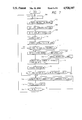
- FIG. 3 shows a flow chart of the processing operation executed by a microprocessor in the user's device to implement the method of the embodiment of FIG. 2;
- FIG. 4 is a functional block diagram showing the operation of a signal receiving method according to another embodiment of the present invention.
- FIG. 5a and 5b show a flow chart of the processing operation executed by a microprocessor in the user's device to implement the method of the another embodiment
- FIG. 6 is a functional block diagram showing the operation of a signal receiving method according to still another embodiment of the present invention.
- FIG. 7 shows a flow chart of the processing operation executed by a microprocessor in the user's device to implement the method of the still another embodiment.
- FIG. 1 shows an overall configuration of a user's device of the GPS.
- reference numeral 1 denotes an antenna for receiving signals transmitted from GPS satellites A, B, C, D, E and F.
- R a , R b , R c , R d , R e and R f indicate so called pseudo ranges between the respective satellites and a user, which will be discussed later, again.
- the antenna 1 is coupled to amplifier 3, in which the feeble satellite signals received by the antenna 1 is subject to the amplification and the frequency conversion to be supplied to GPS receiver 5.
- the receiver 5 is provided with four channels, whereby the user's device can receive signals from four satellites simultaneously.
- the receiver 5 there is usually used a known receiver of the spread spectrum demodulation type. Namely, since signals being transmitted from the satellites A, B, C, D, E, F are subject to the spread spectrum modulation, the receiver 5 performs the demodulation on the basis of the inverse spread spectrum and extracts necessary data from the satellite signals.
- a satellite signal usually includes clock data, almanac data, ephemeris data and so on.
- Each channel of the receiver 5 has receiver part 7 and ⁇ t-calculation part 9.
- the receiver part 7 outputs ephemeris data extracted from a received satellite signal
- the ⁇ t-calculation part 9 has its own clock data and calculates a time difference ⁇ t between its own clock data and the clock data extracted from a received satellite signal. Therefore, the time difference ⁇ t means a propagation time of a signal from a satellite to a user.
- the output data of the receiver part 7 and the ⁇ t-calculation part 9 are supplied to microprocessor 11.
- the connection of the channels 2 to 4 to the microprocessor 11 is indicated by single lines, respectively, it is to be understood that they are coupled to the microprocessor 11 in the same manner as the channel 1.
- the predetermined processing as described later is carried out on the basis of the data supplied by the respective channels of the receiver 5, and processed data are supplied to display device 13 to give a user the information of his precise position in the visual form.
- key board 15 is coupled to the microprocessor 11 in order to supply other necessary data thereto.
- FIG. 2 showing the functional block diagram, which includes the function of the signal receiving method according to an embodiment of the present invention, the operation of the user's device as mentioned above will be explained hereinafter.
- a present time t is at first set (block 201).
- the setting of the present time t is performed periodically with an operation period ⁇ .
- One of factors for determining this period ⁇ is the kind of a user, such as satellite, airplane, ship, car and so on.
- the operation period ⁇ is set at about 5 minutes, GDOP values could be maintained less than four, which is a usual target value for the precise positioning.
- the operation period ⁇ is to be decided at such a value that satellites are selectively switched over with GDOP values of combinations of satellites always maintained less than a desired value.
- Almanac data of GPS satellites are set (block 202). Since almanac data of a satellite includes information of an orbit of the satellite, a present position of the satellite can be obtained on the basis of the almanac data, if only a present time is given. Therefore, present positions of all satellites in all orbits can be specified by calculation on the basis of almanac data of those satellites and the present time t (block 203).
- every satellite has a memory for storing its own almanac data and sends out the data toward the earth therefrom.
- a content of the memory is updated by a GPS control station on the ground at regular intervals. Therefore, a user can receive almanac data sent out from a satellite and use it for the determination of a position of a satellite.
- almanac data sent from a satellite are most recent data concerning an orbit of the satellite and may be more accurate, data initially provided in a user's device, as described above, are sufficient for this purpose, since orbit data of a satellite do not change so frequently and, as will be apparent later, no strictly exact position of the satellite is required in this stage of the operation.
- data of the user's own position are set (block 204). Those are sufficient to be such a very rough data that indicate an area of several hundred kilometers around. On the basis of such data, the user's own position is estimated very roughly (block 205).
- satellites to be used for the positioning are determined only. Such satellites re necessary to be determined from among satellites available to a user at that time. For example, satellites, which are located on the side of the earth opposite to the user, are not available to him. Those satellites must be excluded from the consideration. Briefly, only satellites, which are within a user's view, are detected, and such satellites do not change so frequently depending on the position of the user.
- the availability of the respective satellites to the user is judged (block 206). This judgement is done in accordance with such a simple algorithm that a directional vector toward a satellite from the user is directed above or below the horizon. If the directional vector of a satellite is directed above the horizon, the satellite is selected as one of the available satellites, and otherwise it is not.
- satellites to be used for the positioning are determined (block 207). To this end, all the combinations possible, each consisting of three or four selected from among the available satellites, are at first formed, and then GDOP values are calculated with respect to every combination of satellites. A combination of satellites having a smallest GDOP value is selected, whereby three or four satellites included in the selected combination are determined as satellites to be used for the positioning.
- the channels of the receiver 5 are assigned to the respective satellites determined (block 208).
- the microprocessor 11 sets particular codes (called PN codes in the spread spectrum modulation system), which are assigned in advance to the respective satellites determined, in the receiver part 7 of the respective channels of the receiver 5.
- the channel When a channel of the receiver 5 receives such a code, the channel starts the preparation for getting only a signal from a satellite having a code aligned with the code set in the channel from among satellite signals received by the receiver 5. In the spread spectrum system, this operation is known as acquisition and tracking.
- the channel when it was prepared, extracts ephemeris data of the corresponding satellite from the received signal, calculates the time difference ⁇ t and outputs them to the microprocessor 11.
- Ephemeris data include information of a three dimensional position of a corresponding satellite.
- the ephemeris data is similar to the almanac data, however the accuracy of data is different to the great extent.
- the ephemeris data can provide the positional information of a satellite at the accuracy of less than ten meters, whereas the almanac data can only provide that at the accuracy of several ten kilometers.
- the processing for the positioning is executed (block 209).
- the four satellites A, B, C, D (cf. FIG. 1) were determined as the satellites to be used and the channels 1 to 4 of the receiver 5 were assigned to the respective satellites in order to receive the signals therefrom.
- the pseudo ranges R a , R b , R c , R d are given by the following formulas: ##EQU2## wherein c is the speed of light, and ⁇ t 1 to ⁇ t 4 represent the time differences measured by the ⁇ t-calculation part 9 of the respective channels 1 to 4 of the receiver 5.
- the thus obtained three dimensional position (U X , U Y , U Z ) of the user is displayed on the appropriate display device 13 (block 210).
- a present time t is set in a predetermined area T s defined within an storage of the microprocessor 11 at step 301.
- the user's own position is estimated roughly, and then at step 303, present positions of all the satellites in all the orbits are calculated on the basis of the almanac data of the respective satellites.
- available satellites are detected on the basis of the relationship of the roughly estimated user's own position and the calculated satellite positions.
- GDOP values are calculated with respect to all the combinations possible, each consisting of four satellites selected from among the available satellites detected at step 304.
- the microprocessor 11 After the determination of the satellites to be used, at step 307, the microprocessor 11 reads out particular codes, which are assigned to the determined satellites, from a table provided therein and sets them in the receiver part 7 of the respective channels of the receiver 5 to thereby assign the channels 1 to 4 to the respective satellites.
- the time differences ⁇ t 1 to ⁇ t 4 concerning the respective satellites to be used are taken in the microprocessor 11 through the corresponding channels, and the pseudo ranges R a , R b , R c and R d are calculated on the basis of the time differences ⁇ t 1 to ⁇ t 4 in accordance with the formulas (2).
- the user's precise position is calculated in accordance with the formulas (1) on the basis of the pseudo ranges calculated at step 308 and the ephemeris data, which are given through the corresponding channels.
- step 310 it is discriminated at step 310 whether or not the time ⁇ has lapsed from the start of the processing operation. If the time ⁇ does not lapse yet, the processing operation returns to step 308, and the calculation of the pseudo ranges and the execution of positioning are repeated on the basis of newly received signals from the same satellites as determined at step 306, until the time t reaches T s + ⁇ .
- the positioning is usually executed with a repetition period of 5 to 30 sec.. Therefore, assuming that the operation period ⁇ , as already described, is set at 5 min., 10 to 60 times of the positioning are repeatedly executed for every time of the calculation of GDOP values.
- step 310 If it is judged at step 310 that the time ⁇ has lapsed, the processing operation jumps back to step 301, and the same processing operation as mentioned above is repeated.
- the positioning is repeatedly executed on the basis of ephemeris data transmitted from the satellites determined at step 306 through one operation period ⁇ . Namely, plural times of the positioning are executed for one time of the calculation of GDOP values. A frequency of carrying out the calculation of GDOP values can be reduced without decreasing a frequency of giving a user the information of his position, with the result that the load of the microprocessor 11 can be remarkably reduced.
- FIG. 4 only shows a relevant part of the functional block diagram of the another embodiment, and the remaining part is the same as that shown in FIG. 2. Further, in the figure, identical blocks to those in FIG. 2 are denoted by identical reference numerals.
- a function of periodically setting a future time t+ ⁇ is newly added (block 401).
- the time t+ ⁇ which is preceded by ⁇ from the present time t set by the function of the block 201, is periodically set.
- the period of setting this future time t+ ⁇ is ⁇ . Namely, in this embodiment, the time, which is preceded by one operation period ⁇ from the present time t, is set as the future time.
- the present time t and the future time t+ ⁇ are both given to the functions of the blocks 203 and 205. Therefore, positions of satellites are calculated with respect to two times, i.e., for the present time t and for the future time t+ ⁇ , and also the user's own position are roughly estimated for the two times t and t+ ⁇ .
- FIGS. 5a and 5b in combination show a flow chart of the processing operation to be executed by the microprocessor 11 to achieve the function as shown in the functional block diagram of FIG. 4.
- step 501 to step 504 is the same as that from step 301 to step 304 in the flow chart of FIG. 3. Namely, satellites available to a user at the time t are detected. Then, at step 505, identifying numbers of the available satellites detected are once stored in a table 1 provided in a storage of the microprocessor 11.
- the future time t+ ⁇ is set by increasing the content of the area T s of the storage by ⁇ .
- steps 507 to 509 the same processing as steps 502 to 504 is repeated, whereby satellites available to the user at the future time t+ ⁇ are detected, and at step 510, identifying numbers of the available satellites detected are stored in a table 2 provided in the storage of the microprocessor 11.
- satellites the identifying numbers of which are stored in common to the tables 1 and 2 are selected.
- combinations of satellites, GDOP values of which are to be calculated are formed in such a manner that satellites stored in common to both the tables 1 and 2 are preferentially selected to be included in the combinations of satellites.
- the three satellites B, D, F common to both are always included to form the combinations of satellites, such as [A, B, D, F], [B, C, D, F], [B, D, E, F], [B, D, F, G] and so on.
- GDOP values are calculated with respect to the thus formed combinations of satellites. Then, at step 513, one of the combinations of satellites with a GDOP value smaller than a desired value is selected; usually a combination with a smallest GDOP value is selected, and satellites included in the selected combination are determined as satellites to be used for the positioning. Next, at step 514, the channels of the receiver 5 are assigned to the thus determined satellites.
- the processing operation thereafter is the same as the corresponding portion (cf. steps 308 to 310) of the flow chart of FIG. 3. Therefore, also in this embodiment, a frequency of carrying out the calculation of GDOP values is decreased, so that the load of the microprocessor 11 can be reduced.
- satellites to be used can be determined from among satellites available to a user as long as possible, and therefore the frequency of the switchover of satellites can be decreased. Accordingly, this embodiment can satisfy one of the important requirements for a user's device of the GPS that the frequency of the switchover of satellites is to be decreased as much as possible.
- the availability of satellites are predicted with respect to a future time, which is preceded by one operation period ⁇ from a present time.
- the future time to be preceded for the prediction is to be determined within the allowable scope of the amount of processing by the microprocessor 11, because the amount of processing increases as the duration between a present time and a future time to be preceded.
- FIG. 6 is a functional block diagram showing a relevant part of the function of the still another embodiment, and the remaining part is the same as that of FIG. 2.
- identical blocks to those in FIG. 2 are denoted by identical reference numerals.
- a function for controlling the switchover of satellites so as not to interrupt the receiving of satellite signals.
- this function controls how to switch over an old satellite to a new satellite without interrupting the receiving of satellite signals.
- satellites to be used in the positioning for a certain operation period are determined (block 207), and then the determined satellites are compared with satellites used in the preceding operation period. If they are different from each other, the switchover of satellites is initiated (block 601), and otherwise, the switchover of satellites never occurs.
- the positioning in that period is executed by continuously using the same as satellites used in the preceding period through the whole duration of that period.
- the switchover operation is initiated.
- a channel of the receiver 5, which is off duty at that time is assigned to a new satellite.
- the assigned channel can not be prepared quickly to get a signal from the new satellite.
- the execution of the positioning is for now done by continuously using all the satellites used in the preceding period.
- the positioning is executed by using the satellites including the new satellite switched over. Accordingly, the positioning can be executed without a break even during the switchover of satellites.
- the receiver 5 is necessary to be provided with at least one spare channel.
- the receiver 5 has to be provided with total five channels, which consists of four channels for receiving signals from four satellites and one spare channel.
- the receiver 5 are provided with four channels.
- FIG. 7 shows a flow chart of the processing operation executed by the microprocessor 11 to implement this embodiment.
- step 701 After satellites to be used for the positioning in this operation period are determined at step 706, it is discriminated at step 707 whether or not they are the same as old satellites, which were determined in the preceding operation period and are now on receiving.
- step 706 If they are the same as the old satellites, e.g., if when the old satellites are A, B, C, D, those satellites are determined again at step 706, the processing operation jumps to step 713, and thereafter the same processing operation as the corresponding portion of the flow chart of FIG. 3, i.e., steps 308 to 310, is carried out. Further, it is to be noted that the newly determined satellites in step 713 are the same as the old satellites A, B, C, D in this case.
- step 707 If it is judged at step 707 that they are not the same, the processing operation goes to step 708. For example, if the satellites determined at step 706 are B, C, D, E, the satellite E is new. Then, at step 708, a spare channel of the receiver 5 is assigned to the satellite E, whereby the spare channel starts the preparation for receiving a signal from the satellite E. After that, the microprocessor 11 performs the processing operation of step 709 and the following steps.
- first to fourth channels of the receiver 5 are still on duty and receive signals from the old satellites A, B, C, D. Therefore, in those channels, the respective time differences ⁇ t 1 to ⁇ t 4 are calculated on the received satellite signals.
- the microprocessor 11 takes therein the time differences ⁇ t 1 to ⁇ t 4 and calculates the pseudo ranges R a , R b , R c , R d between the old satellites A, B, C, D and the user. Then, at step 710, the positioning is executed on the basis of the thus calculated pseudo ranges R a , R b , R c , R d and ephemeris data extracted from the signals of the satellites A, B, C, D.
- step 711 After the aforesaid execution of positioning, it is discriminated at step 711 whether or not there is another satellite to be switched over, i.e., whether or not there is in the newly determined satellites included another satellite different from the old satellites. Further, the aforesaid preparation of the spare channel of the receiver 5 is usually completed till step 711.
- step 711 If it is judged at step 711 that there is no longer any different satellite, i.e., a satellite to be switched over, the processing operation goes to step 713, at which the microprocessor 11 takes therein the time differences ⁇ t 2 to ⁇ t 5 , wherein ⁇ t 5 is the time difference produced by the spare channel now on duty, and calculates the pseudo ranges R b , R c , R d , R e between the newly determined satellites B, C, D, E and the user.
- step 714 the positioning is executed on the basis of the thus calculated pseudo ranges R b , R c , R d , R e and ephemeris data extracted from the signals of the satellites B, C, D, E. Thereafter, it is discriminated at step 715 whether or not the time ⁇ has lapsed. If the time ⁇ does not lapse yet, the processing operation returns to step 713 and repeats the execution of the positioning. Otherwise, the processing operation jumps back to step 701 and the same operation as mentioned above is repeated.
- step 706 if the satellites determined at step 706 are C, D, E, F, it is judged at step 711 that there still exists a satellite to be switched over, i.e., from the satellite B to the satellite F. Then, the processing operation returns to step 708 through step 712. At step 712, a new spare channel is prepared by releasing the first channel, which was assigned to the satellite A so far, therefrom, and at step 708, the thus prepared spare channel is newly assigned to the satellite F.
- different satellites are switched over one by one, in the case where one spare channel is provided in the receiver 5. If two spare channels are provided, the switchover of satellites can be carried out two satellites at a time. As a result, the switchover of satellites can be performed without a break.
Abstract
Description
Claims (14)
Applications Claiming Priority (2)
| Application Number | Priority Date | Filing Date | Title |
|---|---|---|---|
| JP63152215A JP2609292B2 (en) | 1988-06-22 | 1988-06-22 | GPS positioning device |
| JP63-152215 | 1988-06-22 |
Publications (1)
| Publication Number | Publication Date |
|---|---|
| US4928107A true US4928107A (en) | 1990-05-22 |
Family
ID=15535591
Family Applications (1)
| Application Number | Title | Priority Date | Filing Date |
|---|---|---|---|
| US07/367,665 Expired - Lifetime US4928107A (en) | 1988-06-22 | 1989-06-19 | Signal receiving method for a user's device in a global positioning system |
Country Status (4)
| Country | Link |
|---|---|
| US (1) | US4928107A (en) |
| EP (1) | EP0353849B1 (en) |
| JP (1) | JP2609292B2 (en) |
| DE (1) | DE68908641T2 (en) |
Cited By (92)
| Publication number | Priority date | Publication date | Assignee | Title |
|---|---|---|---|---|
| US4983980A (en) * | 1989-11-02 | 1991-01-08 | Pioneer Electronic Corporation | Satellite radio signal tracking method for GPS receivers |
| US5155491A (en) * | 1989-11-21 | 1992-10-13 | Pioneer Electronic Corporation | Satellite radio signal tracking method for gps receivers |
| US5202694A (en) * | 1991-09-10 | 1993-04-13 | Trimble Navigation | P-code generation |
| US5222245A (en) * | 1990-03-20 | 1993-06-22 | Pioneer Electronic Corporation | Gps receiver |
| US5276451A (en) * | 1991-07-09 | 1994-01-04 | Pioneer Electronic Corporation | Navigation system with navigational data processing |
| US5293318A (en) * | 1991-07-10 | 1994-03-08 | Pioneer Electronic Corporation | Navigation system |
| US5341301A (en) * | 1990-12-27 | 1994-08-23 | Nippondenso Co., Ltd. | Diversity type global positioning system for motor vehicles |
| US5351059A (en) * | 1989-08-24 | 1994-09-27 | Toshio Tsuyuki | Navigation system and method therefor |
| US5375059A (en) * | 1990-02-05 | 1994-12-20 | Caterpillar Inc. | Vehicle position determination system and method |
| US5450329A (en) * | 1993-12-22 | 1995-09-12 | Tanner; Jesse H. | Vehicle location method and system |
| US5465289A (en) * | 1993-03-05 | 1995-11-07 | E-Systems, Inc. | Cellular based traffic sensor system |
| US5483456A (en) * | 1992-11-04 | 1996-01-09 | Pioneer Electronic Corporation | Navigation system and a method of calculating GPS measuring deviation |
| US5579014A (en) * | 1995-01-20 | 1996-11-26 | General Electric Company | Parallel correlator for global positioning system receiver |
| US5587715A (en) * | 1993-03-19 | 1996-12-24 | Gps Mobile, Inc. | Method and apparatus for tracking a moving object |
| US5598339A (en) * | 1990-03-06 | 1997-01-28 | Pioneer Electronic Corporation | Navigation apparatus for vehicles |
| US5983161A (en) * | 1993-08-11 | 1999-11-09 | Lemelson; Jerome H. | GPS vehicle collision avoidance warning and control system and method |
| US6040800A (en) * | 1997-04-22 | 2000-03-21 | Ericsson Inc. | Systems and methods for locating remote terminals in radiocommunication systems |
| US6057800A (en) * | 1996-06-28 | 2000-05-02 | State University Of New York | RDOP surface for GPS relative positioning |
| US6175806B1 (en) * | 1993-07-16 | 2001-01-16 | Caterpillar Inc. | Method and apparatus for detecting cycle slips in navigation signals received at a receiver from a satellite-based navigation system |
| US6324474B1 (en) | 1998-02-27 | 2001-11-27 | Lockhead Martin Corporation | Method for establishing coverage area and accuracy of a wide-area differential global positioning system |
| WO2002068981A2 (en) * | 2001-02-22 | 2002-09-06 | Motorola, Inc. | Memory reduction method for a dsp-based gps processor |
| US20030008666A1 (en) * | 2001-07-09 | 2003-01-09 | Yuji Ohmura | Positioning system |
| US20030109244A1 (en) * | 1996-02-28 | 2003-06-12 | Tendler Robert K. | Location based service request system |
| US6583759B2 (en) * | 2000-09-01 | 2003-06-24 | Nokia Mobile Phones Ltd | Method for determining a position, a positioning system, and an electronic device |
| US20030197641A1 (en) * | 2002-04-19 | 2003-10-23 | Enuvis, Inc. | Method for optimal search scheduling in satellite acquisition |
| US6650288B1 (en) * | 2002-05-23 | 2003-11-18 | Telecommunication Systems | Culled satellite ephemeris information for quick assisted GPS location determination |
| US20030231132A1 (en) * | 2002-06-12 | 2003-12-18 | Samsung Electronics Co., Ltd. | Method and apparatus for selecting optimal satellites in global positioning system |
| US20050195107A1 (en) * | 2004-03-05 | 2005-09-08 | Kotaro Wakamatsu | Satellite positioning apparatus and method |
| US20050208986A1 (en) * | 2004-03-17 | 2005-09-22 | Best Fiona S | Four frequency band single GSM antenna |
| US20050210235A1 (en) * | 2004-03-17 | 2005-09-22 | Best Fiona S | Encryption STE communications through private branch exchange (PBX) |
| US20050210234A1 (en) * | 2004-03-17 | 2005-09-22 | Best Fiona S | Reach-back communications terminal with selectable networking options |
| US20050222768A1 (en) * | 2004-04-05 | 2005-10-06 | Denso Corporation | Satellite navigation controller |
| US20060217885A1 (en) * | 2005-03-24 | 2006-09-28 | Mark Crady | User location driven identification of service vehicles |
| US20060250304A1 (en) * | 2005-05-06 | 2006-11-09 | Jun Mo | System and method for fast initialization of navigational satellite signal receivers |
| US20060262875A1 (en) * | 2005-05-17 | 2006-11-23 | Madhavan Sethu K | Data transmission method with phase shift error correction |
| US20060270451A1 (en) * | 2004-03-17 | 2006-11-30 | Best Fiona S | Secure transmission over satellite phone network |
| US20070092024A1 (en) * | 2005-10-24 | 2007-04-26 | General Motors Corporation | Method for data communication via a voice channel of a wireless communication network |
| US20070152877A1 (en) * | 2005-12-30 | 2007-07-05 | General Motors Corporation | Method of improving a vehicle emergency call network |
| US20070164553A1 (en) * | 2006-01-17 | 2007-07-19 | Dov Katz | Coloring book with embedded inwardly foldable stencils |
| US20070190950A1 (en) * | 2006-02-15 | 2007-08-16 | General Motors Corporation | Method of configuring voice and data communication over a voice channel |
| US20070258398A1 (en) * | 2005-10-24 | 2007-11-08 | General Motors Corporation | Method for data communication via a voice channel of a wireless communication network |
| US7305243B1 (en) | 1996-02-28 | 2007-12-04 | Tendler Cellular, Inc. | Location based information system |
| US20080014965A1 (en) * | 1991-12-26 | 2008-01-17 | Emsat Advanced Geo-Location Technology, Llc | Cellular telephone system that uses position of a mobile unit to make call management decisions |
| US20080020783A1 (en) * | 2004-10-15 | 2008-01-24 | Pitt Lance D | Other cell sites used as reference point to cull satellite ephemeris information for quick, accurate assisted locating satellite location determination |
| US20080247484A1 (en) * | 2007-04-03 | 2008-10-09 | General Motors Corporation | Method for data communication via a voice channel of a wireless communication network using continuous signal modulation |
| US20080255828A1 (en) * | 2005-10-24 | 2008-10-16 | General Motors Corporation | Data communication via a voice channel of a wireless communication network using discontinuities |
| US20080273644A1 (en) * | 2007-05-03 | 2008-11-06 | Elizabeth Chesnutt | Synchronization and segment type detection method for data transmission via an audio communication system |
| US20080284648A1 (en) * | 2002-06-26 | 2008-11-20 | Sony Corporation | Information terminal apparatus, information processing apparatus and information communication system |
| US20080291979A1 (en) * | 2005-11-29 | 2008-11-27 | Nordnav Technologies Ab | Method and Spread Spectrum Software Receiver for Satellite Navigation |
| US7471236B1 (en) | 2006-03-01 | 2008-12-30 | Telecommunication Systems, Inc. | Cellular augmented radar/laser detector |
| US7489273B2 (en) | 2004-10-15 | 2009-02-10 | Telecommunication Systems, Inc. | Culled satellite ephemeris information for quick, accurate assisted locating satellite location determination for cell site antennas |
| US20090051590A1 (en) * | 2004-10-15 | 2009-02-26 | Lance Douglas Pitt | Culled satellite ephemeris information for quick, accurate assisted locating satellite location determination for cell site antennas |
| US20100090827A1 (en) * | 2008-10-14 | 2010-04-15 | Todd Gehrke | Location based proximity alert |
| US20100117901A1 (en) * | 2008-11-11 | 2010-05-13 | Seiko Epson Corporation | Position calculating method and position calculating device |
| US7737841B2 (en) | 2006-07-14 | 2010-06-15 | Remotemdx | Alarm and alarm management system for remote tracking devices |
| US20100171655A1 (en) * | 2007-12-07 | 2010-07-08 | Andrew Llc | Method and system for selecting optimal satellites for a-gps location of handsets in wireless networks |
| US20100176992A1 (en) * | 2007-07-31 | 2010-07-15 | T Siobbel Stephen | Method and device for determining a position |
| US7782254B2 (en) | 2004-10-15 | 2010-08-24 | Telecommunication Systems, Inc. | Culled satellite ephemeris information based on limiting a span of an inverted cone for locating satellite in-range determinations |
| US7804412B2 (en) | 2005-08-10 | 2010-09-28 | Securealert, Inc. | Remote tracking and communication device |
| US7825780B2 (en) | 2005-10-05 | 2010-11-02 | Telecommunication Systems, Inc. | Cellular augmented vehicle alarm notification together with location services for position of an alarming vehicle |
| US7899450B2 (en) | 2006-03-01 | 2011-03-01 | Telecommunication Systems, Inc. | Cellular augmented radar/laser detection using local mobile network within cellular network |
| US7936262B2 (en) | 2006-07-14 | 2011-05-03 | Securealert, Inc. | Remote tracking system with a dedicated monitoring center |
| US8126889B2 (en) | 2002-03-28 | 2012-02-28 | Telecommunication Systems, Inc. | Location fidelity adjustment based on mobile subscriber privacy profile |
| US20120072112A1 (en) * | 2010-09-20 | 2012-03-22 | Peter Bagnall | Signal verification |
| US8208605B2 (en) | 2006-05-04 | 2012-06-26 | Telecommunication Systems, Inc. | Extended efficient usage of emergency services keys |
| US8232876B2 (en) | 2008-03-07 | 2012-07-31 | Securealert, Inc. | System and method for monitoring individuals using a beacon and intelligent remote tracking device |
| US8315599B2 (en) | 2010-07-09 | 2012-11-20 | Telecommunication Systems, Inc. | Location privacy selector |
| US8336664B2 (en) | 2010-07-09 | 2012-12-25 | Telecommunication Systems, Inc. | Telematics basic mobile device safety interlock |
| US20130002485A1 (en) * | 2011-01-05 | 2013-01-03 | Cambridge Silicon Radio Limited | Satellite Subset Selection |
| US20130021198A1 (en) * | 2011-01-05 | 2013-01-24 | Cambridge Silicon Radio Limited | Convergence Zone |
| US8369967B2 (en) | 1999-02-01 | 2013-02-05 | Hoffberg Steven M | Alarm system controller and a method for controlling an alarm system |
| US8369825B2 (en) | 2003-12-19 | 2013-02-05 | Telecommunication Systems, Inc. | Enhanced E911 network access for a call center using session initiation protocol (SIP) messaging |
| US8514070B2 (en) | 2010-04-07 | 2013-08-20 | Securealert, Inc. | Tracking device incorporating enhanced security mounting strap |
| US8666397B2 (en) | 2002-12-13 | 2014-03-04 | Telecommunication Systems, Inc. | Area event handling when current network does not cover target area |
| US8688174B2 (en) | 2012-03-13 | 2014-04-01 | Telecommunication Systems, Inc. | Integrated, detachable ear bud device for a wireless phone |
| CN103954982A (en) * | 2014-04-18 | 2014-07-30 | 中国人民解放军国防科学技术大学 | Rapid visible satellite selection method based on multimode GNSS receiver |
| US8797210B2 (en) | 2006-07-14 | 2014-08-05 | Securealert, Inc. | Remote tracking device and a system and method for two-way voice communication between the device and a monitoring center |
| US8892495B2 (en) | 1991-12-23 | 2014-11-18 | Blanding Hovenweep, Llc | Adaptive pattern recognition based controller apparatus and method and human-interface therefore |
| US8892128B2 (en) | 2008-10-14 | 2014-11-18 | Telecommunication Systems, Inc. | Location based geo-reminders |
| US9030355B2 (en) | 2011-01-05 | 2015-05-12 | Cambridge Silicon Radio Limited | Location fix from unknown position |
| US9151633B2 (en) | 1998-01-27 | 2015-10-06 | Steven M. Hoffberg | Mobile communication device for delivering targeted advertisements |
| US9167553B2 (en) | 2006-03-01 | 2015-10-20 | Telecommunication Systems, Inc. | GeoNexus proximity detector network |
| US9198054B2 (en) | 2011-09-02 | 2015-11-24 | Telecommunication Systems, Inc. | Aggregate location dynometer (ALD) |
| US9197992B2 (en) | 2003-12-19 | 2015-11-24 | Telecommunication Systems, Inc. | User plane location services over session initiation protocol (SIP) |
| US9307372B2 (en) | 2012-03-26 | 2016-04-05 | Telecommunication Systems, Inc. | No responders online |
| US9322922B2 (en) | 2011-01-05 | 2016-04-26 | Qualcomm Technologies International, Ltd. | Determining position of a GNSS receiver using fractional signalling event period times |
| US9384339B2 (en) | 2012-01-13 | 2016-07-05 | Telecommunication Systems, Inc. | Authenticating cloud computing enabling secure services |
| US9479344B2 (en) | 2011-09-16 | 2016-10-25 | Telecommunication Systems, Inc. | Anonymous voice conversation |
| CN106501828A (en) * | 2016-09-26 | 2017-03-15 | 闽江学院 | A kind of high accuracy pseudo range one-point positioning method weighted based on fuzzy logic |
| US10361802B1 (en) | 1999-02-01 | 2019-07-23 | Blanding Hovenweep, Llc | Adaptive pattern recognition based control system and method |
| US10943273B2 (en) | 2003-02-05 | 2021-03-09 | The Hoffberg Family Trust 2004-1 | System and method for determining contingent relevance |
| US11237275B2 (en) | 2015-09-17 | 2022-02-01 | Mitsubishi Electric Corporation | Positioning satellite selection device, positioning information transmitting device, and positioning system |
Families Citing this family (9)
| Publication number | Priority date | Publication date | Assignee | Title |
|---|---|---|---|---|
| US6560461B1 (en) | 1997-08-04 | 2003-05-06 | Mundi Fomukong | Authorized location reporting paging system |
| CA2404109C (en) * | 2000-03-20 | 2011-04-26 | Qualcomm Incorporated | Methods and apparatuses for using assistance data relating to satellite position systems |
| JP3922585B2 (en) * | 2004-05-13 | 2007-05-30 | セイコーエプソン株式会社 | POSITIONING DEVICE, POSITIONING METHOD, POSITIONING PROGRAM, COMPUTER-READABLE RECORDING MEDIUM CONTAINING POSITIONING PROGRAM |
| DE102004057367A1 (en) * | 2004-11-27 | 2006-06-01 | Zexel Valeo Compressor Europe Gmbh | axial piston |
| JP4978337B2 (en) * | 2007-06-28 | 2012-07-18 | 富士通東芝モバイルコミュニケーションズ株式会社 | Mobile device |
| JP5283439B2 (en) * | 2008-07-04 | 2013-09-04 | 日本無線株式会社 | Satellite navigation system |
| CN104820228A (en) * | 2015-04-30 | 2015-08-05 | 厦门大学 | Global satellite navigation system receiver constellation optimal selection method |
| CN107402395A (en) * | 2017-05-17 | 2017-11-28 | 西安交通大学 | A kind of satellite selection method to be navigated for single system and multisystem combinations of satellites |
| US10845487B2 (en) * | 2017-06-13 | 2020-11-24 | Microsoft Technology Licensing, Llc | Acquisition in global navigation satellite systems based on previously acquired satellites |
Family Cites Families (3)
| Publication number | Priority date | Publication date | Assignee | Title |
|---|---|---|---|---|
| JPS61770A (en) * | 1984-06-13 | 1986-01-06 | Sony Corp | Gps receiver |
| JPS62276478A (en) * | 1986-05-26 | 1987-12-01 | Nissan Motor Co Ltd | Apparatus for measuring gps position |
| JPS63281U (en) * | 1986-06-18 | 1988-01-05 |
-
1988
- 1988-06-22 JP JP63152215A patent/JP2609292B2/en not_active Expired - Fee Related
-
1989
- 1989-06-19 US US07/367,665 patent/US4928107A/en not_active Expired - Lifetime
- 1989-06-22 DE DE89306293T patent/DE68908641T2/en not_active Expired - Fee Related
- 1989-06-22 EP EP89306293A patent/EP0353849B1/en not_active Expired - Lifetime
Cited By (158)
| Publication number | Priority date | Publication date | Assignee | Title |
|---|---|---|---|---|
| US5351059A (en) * | 1989-08-24 | 1994-09-27 | Toshio Tsuyuki | Navigation system and method therefor |
| US4983980A (en) * | 1989-11-02 | 1991-01-08 | Pioneer Electronic Corporation | Satellite radio signal tracking method for GPS receivers |
| US5155491A (en) * | 1989-11-21 | 1992-10-13 | Pioneer Electronic Corporation | Satellite radio signal tracking method for gps receivers |
| US5438517A (en) * | 1990-02-05 | 1995-08-01 | Caterpillar Inc. | Vehicle position determination system and method |
| US5375059A (en) * | 1990-02-05 | 1994-12-20 | Caterpillar Inc. | Vehicle position determination system and method |
| US5390125A (en) * | 1990-02-05 | 1995-02-14 | Caterpillar Inc. | Vehicle position determination system and method |
| US5752219A (en) * | 1990-03-06 | 1998-05-12 | Pioneer Electronic Corporation | Navigation apparatus for vehicles |
| US5598339A (en) * | 1990-03-06 | 1997-01-28 | Pioneer Electronic Corporation | Navigation apparatus for vehicles |
| US5222245A (en) * | 1990-03-20 | 1993-06-22 | Pioneer Electronic Corporation | Gps receiver |
| US5341301A (en) * | 1990-12-27 | 1994-08-23 | Nippondenso Co., Ltd. | Diversity type global positioning system for motor vehicles |
| US5276451A (en) * | 1991-07-09 | 1994-01-04 | Pioneer Electronic Corporation | Navigation system with navigational data processing |
| US5293318A (en) * | 1991-07-10 | 1994-03-08 | Pioneer Electronic Corporation | Navigation system |
| US5202694A (en) * | 1991-09-10 | 1993-04-13 | Trimble Navigation | P-code generation |
| US8892495B2 (en) | 1991-12-23 | 2014-11-18 | Blanding Hovenweep, Llc | Adaptive pattern recognition based controller apparatus and method and human-interface therefore |
| US20080014965A1 (en) * | 1991-12-26 | 2008-01-17 | Emsat Advanced Geo-Location Technology, Llc | Cellular telephone system that uses position of a mobile unit to make call management decisions |
| US5483456A (en) * | 1992-11-04 | 1996-01-09 | Pioneer Electronic Corporation | Navigation system and a method of calculating GPS measuring deviation |
| US5465289A (en) * | 1993-03-05 | 1995-11-07 | E-Systems, Inc. | Cellular based traffic sensor system |
| US5587715A (en) * | 1993-03-19 | 1996-12-24 | Gps Mobile, Inc. | Method and apparatus for tracking a moving object |
| US5796365A (en) * | 1993-03-19 | 1998-08-18 | Lewis; Peter T. | Method and apparatus for tracking a moving object |
| US6175806B1 (en) * | 1993-07-16 | 2001-01-16 | Caterpillar Inc. | Method and apparatus for detecting cycle slips in navigation signals received at a receiver from a satellite-based navigation system |
| US5983161A (en) * | 1993-08-11 | 1999-11-09 | Lemelson; Jerome H. | GPS vehicle collision avoidance warning and control system and method |
| US6487500B2 (en) | 1993-08-11 | 2002-11-26 | Jerome H. Lemelson | GPS vehicle collision avoidance warning and control system and method |
| US6275773B1 (en) | 1993-08-11 | 2001-08-14 | Jerome H. Lemelson | GPS vehicle collision avoidance warning and control system and method |
| US5450329A (en) * | 1993-12-22 | 1995-09-12 | Tanner; Jesse H. | Vehicle location method and system |
| US5579014A (en) * | 1995-01-20 | 1996-11-26 | General Electric Company | Parallel correlator for global positioning system receiver |
| US7305243B1 (en) | 1996-02-28 | 2007-12-04 | Tendler Cellular, Inc. | Location based information system |
| US7050818B2 (en) | 1996-02-28 | 2006-05-23 | Tendler Cellular, Inc. | Location based service request system |
| US7844282B1 (en) | 1996-02-28 | 2010-11-30 | Tendler Robert K | Location based information system |
| US20030109244A1 (en) * | 1996-02-28 | 2003-06-12 | Tendler Robert K. | Location based service request system |
| US7447508B1 (en) | 1996-02-28 | 2008-11-04 | Tendler Cellular, Inc. | Location based information system |
| US6057800A (en) * | 1996-06-28 | 2000-05-02 | State University Of New York | RDOP surface for GPS relative positioning |
| US6040800A (en) * | 1997-04-22 | 2000-03-21 | Ericsson Inc. | Systems and methods for locating remote terminals in radiocommunication systems |
| US9151633B2 (en) | 1998-01-27 | 2015-10-06 | Steven M. Hoffberg | Mobile communication device for delivering targeted advertisements |
| US9551582B2 (en) | 1998-01-27 | 2017-01-24 | Blanding Hovenweep, Llc | Mobile communication device |
| US10127816B2 (en) | 1998-01-27 | 2018-11-13 | Blanding Hovenweep, Llc | Detection and alert of automobile braking event |
| US6324474B1 (en) | 1998-02-27 | 2001-11-27 | Lockhead Martin Corporation | Method for establishing coverage area and accuracy of a wide-area differential global positioning system |
| US9535563B2 (en) | 1999-02-01 | 2017-01-03 | Blanding Hovenweep, Llc | Internet appliance system and method |
| US10361802B1 (en) | 1999-02-01 | 2019-07-23 | Blanding Hovenweep, Llc | Adaptive pattern recognition based control system and method |
| US8369967B2 (en) | 1999-02-01 | 2013-02-05 | Hoffberg Steven M | Alarm system controller and a method for controlling an alarm system |
| US6583759B2 (en) * | 2000-09-01 | 2003-06-24 | Nokia Mobile Phones Ltd | Method for determining a position, a positioning system, and an electronic device |
| WO2002068981A2 (en) * | 2001-02-22 | 2002-09-06 | Motorola, Inc. | Memory reduction method for a dsp-based gps processor |
| CN1963558B (en) * | 2001-02-22 | 2012-06-27 | SiRF技术公司 | Minimization of a GPS satellite search time in a gps receiver |
| WO2002068981A3 (en) * | 2001-02-22 | 2003-04-24 | Motorola Inc | Memory reduction method for a dsp-based gps processor |
| US6917330B2 (en) * | 2001-07-09 | 2005-07-12 | Mitsubishi Denki Kabushiki Kaisha | Positioning system |
| US20030008666A1 (en) * | 2001-07-09 | 2003-01-09 | Yuji Ohmura | Positioning system |
| US8126889B2 (en) | 2002-03-28 | 2012-02-28 | Telecommunication Systems, Inc. | Location fidelity adjustment based on mobile subscriber privacy profile |
| US6836241B2 (en) * | 2002-04-19 | 2004-12-28 | Sirf Technology, Inc. | Method for optimal search scheduling in satellite acquisition |
| US20030197641A1 (en) * | 2002-04-19 | 2003-10-23 | Enuvis, Inc. | Method for optimal search scheduling in satellite acquisition |
| US6650288B1 (en) * | 2002-05-23 | 2003-11-18 | Telecommunication Systems | Culled satellite ephemeris information for quick assisted GPS location determination |
| US20030231132A1 (en) * | 2002-06-12 | 2003-12-18 | Samsung Electronics Co., Ltd. | Method and apparatus for selecting optimal satellites in global positioning system |
| US6727850B2 (en) * | 2002-06-12 | 2004-04-27 | Samsung Electronics Co., Ltd. | Method and apparatus for selecting optimal satelittes in global positioning system |
| US8489881B2 (en) * | 2002-06-26 | 2013-07-16 | Sony Corporation | Information terminal apparatus, information processing apparatus and information communication system |
| US20080284648A1 (en) * | 2002-06-26 | 2008-11-20 | Sony Corporation | Information terminal apparatus, information processing apparatus and information communication system |
| US8666397B2 (en) | 2002-12-13 | 2014-03-04 | Telecommunication Systems, Inc. | Area event handling when current network does not cover target area |
| US11790413B2 (en) | 2003-02-05 | 2023-10-17 | Hoffberg Family Trust 2 | System and method for communication |
| US10943273B2 (en) | 2003-02-05 | 2021-03-09 | The Hoffberg Family Trust 2004-1 | System and method for determining contingent relevance |
| US9197992B2 (en) | 2003-12-19 | 2015-11-24 | Telecommunication Systems, Inc. | User plane location services over session initiation protocol (SIP) |
| US8369825B2 (en) | 2003-12-19 | 2013-02-05 | Telecommunication Systems, Inc. | Enhanced E911 network access for a call center using session initiation protocol (SIP) messaging |
| US7295155B2 (en) * | 2004-03-05 | 2007-11-13 | Alpine Electronics, Inc. | Satellite positioning apparatus and method |
| US20050195107A1 (en) * | 2004-03-05 | 2005-09-08 | Kotaro Wakamatsu | Satellite positioning apparatus and method |
| US20100124330A1 (en) * | 2004-03-17 | 2010-05-20 | Best Fiona S | Secure transmission over satellite phone network |
| US8489874B2 (en) | 2004-03-17 | 2013-07-16 | Telecommunication Systems, Inc. | Encryption STE communications through private branch exchange (PBX) |
| US20060271779A1 (en) * | 2004-03-17 | 2006-11-30 | Best Fiona S | Faceplate for quick removal and securing of encryption device |
| US20050210234A1 (en) * | 2004-03-17 | 2005-09-22 | Best Fiona S | Reach-back communications terminal with selectable networking options |
| US7890051B2 (en) | 2004-03-17 | 2011-02-15 | Telecommunication Systems, Inc. | Secure transmission over satellite phone network |
| US8239669B2 (en) | 2004-03-17 | 2012-08-07 | Telecommunication Systems, Inc. | Reach-back communications terminal with selectable networking options |
| US20060270451A1 (en) * | 2004-03-17 | 2006-11-30 | Best Fiona S | Secure transmission over satellite phone network |
| US7761095B2 (en) | 2004-03-17 | 2010-07-20 | Telecommunication Systems, Inc. | Secure transmission over satellite phone network |
| US20110237247A1 (en) * | 2004-03-17 | 2011-09-29 | Best Fiona S | Secure transmission over satellite phone network |
| US8913989B2 (en) | 2004-03-17 | 2014-12-16 | Telecommunication Systems, Inc. | Secure transmission over satellite phone network |
| US20050208986A1 (en) * | 2004-03-17 | 2005-09-22 | Best Fiona S | Four frequency band single GSM antenna |
| US8280466B2 (en) | 2004-03-17 | 2012-10-02 | Telecommunication Systems, Inc. | Four frequency band single GSM antenna |
| US20050210235A1 (en) * | 2004-03-17 | 2005-09-22 | Best Fiona S | Encryption STE communications through private branch exchange (PBX) |
| US7724902B2 (en) | 2004-03-17 | 2010-05-25 | Telecommunication Systems, Inc. | Faceplate for quick removal and securing of encryption device |
| US20050222768A1 (en) * | 2004-04-05 | 2005-10-06 | Denso Corporation | Satellite navigation controller |
| US7392134B2 (en) * | 2004-04-05 | 2008-06-24 | Denso Corporation | Satellite navigation controller |
| US7489273B2 (en) | 2004-10-15 | 2009-02-10 | Telecommunication Systems, Inc. | Culled satellite ephemeris information for quick, accurate assisted locating satellite location determination for cell site antennas |
| US7782254B2 (en) | 2004-10-15 | 2010-08-24 | Telecommunication Systems, Inc. | Culled satellite ephemeris information based on limiting a span of an inverted cone for locating satellite in-range determinations |
| US7629926B2 (en) | 2004-10-15 | 2009-12-08 | Telecommunication Systems, Inc. | Culled satellite ephemeris information for quick, accurate assisted locating satellite location determination for cell site antennas |
| US8089401B2 (en) | 2004-10-15 | 2012-01-03 | Telecommunication Systems, Inc. | Culled satellite ephemeris information for quick, accurate assisted locating satellite location determination for cell site antennas |
| US20090051590A1 (en) * | 2004-10-15 | 2009-02-26 | Lance Douglas Pitt | Culled satellite ephemeris information for quick, accurate assisted locating satellite location determination for cell site antennas |
| US8681044B2 (en) | 2004-10-15 | 2014-03-25 | Telecommunication Systems, Inc. | Culled satellite ephemeris information for quick, accurate assisted locating satellite location determination for cell site antennas |
| US20080020783A1 (en) * | 2004-10-15 | 2008-01-24 | Pitt Lance D | Other cell sites used as reference point to cull satellite ephemeris information for quick, accurate assisted locating satellite location determination |
| US7411546B2 (en) | 2004-10-15 | 2008-08-12 | Telecommunication Systems, Inc. | Other cell sites used as reference point to cull satellite ephemeris information for quick, accurate assisted locating satellite location determination |
| US20060217885A1 (en) * | 2005-03-24 | 2006-09-28 | Mark Crady | User location driven identification of service vehicles |
| US8370054B2 (en) | 2005-03-24 | 2013-02-05 | Google Inc. | User location driven identification of service vehicles |
| US20060250304A1 (en) * | 2005-05-06 | 2006-11-09 | Jun Mo | System and method for fast initialization of navigational satellite signal receivers |
| US7324045B2 (en) * | 2005-05-06 | 2008-01-29 | Sirf Technology, Inc. | System and method for fast initialization of navigational satellite signal receivers |
| US8054924B2 (en) | 2005-05-17 | 2011-11-08 | General Motors Llc | Data transmission method with phase shift error correction |
| US20060262875A1 (en) * | 2005-05-17 | 2006-11-23 | Madhavan Sethu K | Data transmission method with phase shift error correction |
| US8031077B2 (en) | 2005-08-10 | 2011-10-04 | Securealert, Inc. | Remote tracking and communication device |
| US7804412B2 (en) | 2005-08-10 | 2010-09-28 | Securealert, Inc. | Remote tracking and communication device |
| US7825780B2 (en) | 2005-10-05 | 2010-11-02 | Telecommunication Systems, Inc. | Cellular augmented vehicle alarm notification together with location services for position of an alarming vehicle |
| US8259840B2 (en) | 2005-10-24 | 2012-09-04 | General Motors Llc | Data communication via a voice channel of a wireless communication network using discontinuities |
| US20080255828A1 (en) * | 2005-10-24 | 2008-10-16 | General Motors Corporation | Data communication via a voice channel of a wireless communication network using discontinuities |
| US20070092024A1 (en) * | 2005-10-24 | 2007-04-26 | General Motors Corporation | Method for data communication via a voice channel of a wireless communication network |
| US8194526B2 (en) | 2005-10-24 | 2012-06-05 | General Motors Llc | Method for data communication via a voice channel of a wireless communication network |
| US8194779B2 (en) | 2005-10-24 | 2012-06-05 | General Motors Llc | Method for data communication via a voice channel of a wireless communication network |
| US20070258398A1 (en) * | 2005-10-24 | 2007-11-08 | General Motors Corporation | Method for data communication via a voice channel of a wireless communication network |
| US7864109B2 (en) * | 2005-11-29 | 2011-01-04 | Nordnav Technologies Ab | Method and spread spectrum software receiver for satellite navigation |
| US20080291979A1 (en) * | 2005-11-29 | 2008-11-27 | Nordnav Technologies Ab | Method and Spread Spectrum Software Receiver for Satellite Navigation |
| US20070152877A1 (en) * | 2005-12-30 | 2007-07-05 | General Motors Corporation | Method of improving a vehicle emergency call network |
| US7705775B2 (en) * | 2005-12-30 | 2010-04-27 | General Motors Llc | Method of improving a vehicle emergency call network |
| US20070164553A1 (en) * | 2006-01-17 | 2007-07-19 | Dov Katz | Coloring book with embedded inwardly foldable stencils |
| US20070190950A1 (en) * | 2006-02-15 | 2007-08-16 | General Motors Corporation | Method of configuring voice and data communication over a voice channel |
| US7764219B2 (en) | 2006-03-01 | 2010-07-27 | Telecommunication Systems, Inc. | Cellular augmented radar/laser detector |
| US7965222B2 (en) | 2006-03-01 | 2011-06-21 | Telecommunication Systems, Inc. | Cellular augmented radar/laser detector |
| US9167553B2 (en) | 2006-03-01 | 2015-10-20 | Telecommunication Systems, Inc. | GeoNexus proximity detector network |
| US20100238065A1 (en) * | 2006-03-01 | 2010-09-23 | Lance Douglas Pitt | Cellular augmented radar/laser detector |
| US7471236B1 (en) | 2006-03-01 | 2008-12-30 | Telecommunication Systems, Inc. | Cellular augmented radar/laser detector |
| US8515414B2 (en) | 2006-03-01 | 2013-08-20 | Telecommunication Systems, Inc. | Cellular augmented radar/laser detection using local mobile network within cellular network |
| US7899450B2 (en) | 2006-03-01 | 2011-03-01 | Telecommunication Systems, Inc. | Cellular augmented radar/laser detection using local mobile network within cellular network |
| US9002347B2 (en) | 2006-03-01 | 2015-04-07 | Telecommunication Systems, Inc. | Transmitter augmented radar/laser detection using local mobile network within a wide area network |
| US8208605B2 (en) | 2006-05-04 | 2012-06-26 | Telecommunication Systems, Inc. | Extended efficient usage of emergency services keys |
| US7737841B2 (en) | 2006-07-14 | 2010-06-15 | Remotemdx | Alarm and alarm management system for remote tracking devices |
| US8013736B2 (en) | 2006-07-14 | 2011-09-06 | Securealert, Inc. | Alarm and alarm management system for remote tracking devices |
| US7936262B2 (en) | 2006-07-14 | 2011-05-03 | Securealert, Inc. | Remote tracking system with a dedicated monitoring center |
| US8797210B2 (en) | 2006-07-14 | 2014-08-05 | Securealert, Inc. | Remote tracking device and a system and method for two-way voice communication between the device and a monitoring center |
| US9048784B2 (en) | 2007-04-03 | 2015-06-02 | General Motors Llc | Method for data communication via a voice channel of a wireless communication network using continuous signal modulation |
| US20080247484A1 (en) * | 2007-04-03 | 2008-10-09 | General Motors Corporation | Method for data communication via a voice channel of a wireless communication network using continuous signal modulation |
| US20080273644A1 (en) * | 2007-05-03 | 2008-11-06 | Elizabeth Chesnutt | Synchronization and segment type detection method for data transmission via an audio communication system |
| US7912149B2 (en) | 2007-05-03 | 2011-03-22 | General Motors Llc | Synchronization and segment type detection method for data transmission via an audio communication system |
| US20100176992A1 (en) * | 2007-07-31 | 2010-07-15 | T Siobbel Stephen | Method and device for determining a position |
| US9250330B2 (en) * | 2007-12-07 | 2016-02-02 | Telecommunication Systems, Inc. | Method and system for selecting optimal satellites for A-GPS location of handsets in wireless networks |
| US20100171655A1 (en) * | 2007-12-07 | 2010-07-08 | Andrew Llc | Method and system for selecting optimal satellites for a-gps location of handsets in wireless networks |
| US8232876B2 (en) | 2008-03-07 | 2012-07-31 | Securealert, Inc. | System and method for monitoring individuals using a beacon and intelligent remote tracking device |
| US8525681B2 (en) | 2008-10-14 | 2013-09-03 | Telecommunication Systems, Inc. | Location based proximity alert |
| US8892128B2 (en) | 2008-10-14 | 2014-11-18 | Telecommunication Systems, Inc. | Location based geo-reminders |
| US9467810B2 (en) | 2008-10-14 | 2016-10-11 | Telecommunication Systems, Inc. | Location based geo-reminders |
| US20100090827A1 (en) * | 2008-10-14 | 2010-04-15 | Todd Gehrke | Location based proximity alert |
| US20100117901A1 (en) * | 2008-11-11 | 2010-05-13 | Seiko Epson Corporation | Position calculating method and position calculating device |
| US8154447B2 (en) * | 2008-11-11 | 2012-04-10 | Seiko Epson Corporation | Position calculating method and position calculating device |
| US9129504B2 (en) | 2010-04-07 | 2015-09-08 | Securealert, Inc. | Tracking device incorporating cuff with cut resistant materials |
| US8514070B2 (en) | 2010-04-07 | 2013-08-20 | Securealert, Inc. | Tracking device incorporating enhanced security mounting strap |
| US8315599B2 (en) | 2010-07-09 | 2012-11-20 | Telecommunication Systems, Inc. | Location privacy selector |
| US8336664B2 (en) | 2010-07-09 | 2012-12-25 | Telecommunication Systems, Inc. | Telematics basic mobile device safety interlock |
| US9204294B2 (en) | 2010-07-09 | 2015-12-01 | Telecommunication Systems, Inc. | Location privacy selector |
| US8633852B2 (en) * | 2010-09-20 | 2014-01-21 | Stmicroelectronics (Research & Development) Limited | Signal verification |
| US9140561B2 (en) * | 2010-09-20 | 2015-09-22 | Stmicroelectronics (Research & Development) Limited | Signal verification |
| US20120072112A1 (en) * | 2010-09-20 | 2012-03-22 | Peter Bagnall | Signal verification |
| US20140100778A1 (en) * | 2010-09-20 | 2014-04-10 | Stmicroelectronics (Research & Development) Limited | Signal verification |
| GB2487348B (en) * | 2011-01-05 | 2018-10-03 | Qualcomm Technologies Int Ltd | Calculation of location in a satellite navigation system with extended convergence zone |
| US20130021198A1 (en) * | 2011-01-05 | 2013-01-24 | Cambridge Silicon Radio Limited | Convergence Zone |
| US9322922B2 (en) | 2011-01-05 | 2016-04-26 | Qualcomm Technologies International, Ltd. | Determining position of a GNSS receiver using fractional signalling event period times |
| US9030355B2 (en) | 2011-01-05 | 2015-05-12 | Cambridge Silicon Radio Limited | Location fix from unknown position |
| US9158002B2 (en) * | 2011-01-05 | 2015-10-13 | Qualcomm Incorporated | Satellite subset selection |
| US20130002485A1 (en) * | 2011-01-05 | 2013-01-03 | Cambridge Silicon Radio Limited | Satellite Subset Selection |
| US9086479B2 (en) * | 2011-01-05 | 2015-07-21 | Cambridge Silicon Radio Limited | Convergence zone |
| US9402158B2 (en) | 2011-09-02 | 2016-07-26 | Telecommunication Systems, Inc. | Aggregate location dynometer (ALD) |
| US9198054B2 (en) | 2011-09-02 | 2015-11-24 | Telecommunication Systems, Inc. | Aggregate location dynometer (ALD) |
| US9479344B2 (en) | 2011-09-16 | 2016-10-25 | Telecommunication Systems, Inc. | Anonymous voice conversation |
| US9384339B2 (en) | 2012-01-13 | 2016-07-05 | Telecommunication Systems, Inc. | Authenticating cloud computing enabling secure services |
| US8688174B2 (en) | 2012-03-13 | 2014-04-01 | Telecommunication Systems, Inc. | Integrated, detachable ear bud device for a wireless phone |
| US9307372B2 (en) | 2012-03-26 | 2016-04-05 | Telecommunication Systems, Inc. | No responders online |
| CN103954982A (en) * | 2014-04-18 | 2014-07-30 | 中国人民解放军国防科学技术大学 | Rapid visible satellite selection method based on multimode GNSS receiver |
| US11237275B2 (en) | 2015-09-17 | 2022-02-01 | Mitsubishi Electric Corporation | Positioning satellite selection device, positioning information transmitting device, and positioning system |
| CN106501828B (en) * | 2016-09-26 | 2019-02-26 | 闽江学院 | A kind of high accuracy pseudo range one-point positioning method based on fuzzy logic weighting |
| CN106501828A (en) * | 2016-09-26 | 2017-03-15 | 闽江学院 | A kind of high accuracy pseudo range one-point positioning method weighted based on fuzzy logic |
Also Published As
| Publication number | Publication date |
|---|---|
| JPH01320485A (en) | 1989-12-26 |
| DE68908641T2 (en) | 1994-03-10 |
| JP2609292B2 (en) | 1997-05-14 |
| EP0353849B1 (en) | 1993-08-25 |
| EP0353849A1 (en) | 1990-02-07 |
| DE68908641D1 (en) | 1993-09-30 |
Similar Documents
| Publication | Publication Date | Title |
|---|---|---|
| US4928107A (en) | Signal receiving method for a user's device in a global positioning system | |
| US5248981A (en) | Apparatus and method for positioning of a gps receiver | |
| US5418538A (en) | Rapid satellite signal acquisition in a satellite positioning system | |
| EP1023612B1 (en) | Reduced global positioning system receiver code shift search space for a cellular telephone system | |
| US5245628A (en) | Enhanced l1/l2 code channel for global positioning system receivers | |
| US5341301A (en) | Diversity type global positioning system for motor vehicles | |
| US6653976B1 (en) | Method and apparatus for automatic and autonomous assignment of PRN codes to a multiplicity of pseudolites | |
| EP0635728B1 (en) | Satellite search methods for improving time to first fix in a GPS receiver | |
| US4613864A (en) | Position-fixing system | |
| US6922546B1 (en) | GPS signal acquisition based on frequency-domain and time-domain processing | |
| US6727850B2 (en) | Method and apparatus for selecting optimal satelittes in global positioning system | |
| US5059969A (en) | Gps satellite signal tracking method for gps receivers | |
| US6865478B2 (en) | Determining the position of a receiver and/or the system time of a positioning system | |
| EP0425763B1 (en) | A satellite radio signal tracking method for GPS receivers | |
| EP1116046B1 (en) | Interferometric synthetic aperture radar altimeter | |
| EP2434313B1 (en) | Method for fusing multiple GPS measurement types into a weighted least squares solution | |
| US5486834A (en) | Global orbiting navigation satellite system receiver | |
| EP1744454A2 (en) | Method and apparatus for filtering measurements used in a generalized positioning system | |
| KR20010050336A (en) | Satellite-based location system employing knowledge-based sequential signal search strategy | |
| US6894645B1 (en) | Position estimation | |
| EP1115008A2 (en) | A method for determining reference time error and an electronic device | |
| JP2002071782A (en) | Information terminal with positioning function | |
| JPH0666916A (en) | Gps receiver | |
| EP0451607A2 (en) | Satellite signal acquisition system for GPS receiver | |
| JP3427325B2 (en) | GPS receiver |
Legal Events
| Date | Code | Title | Description |
|---|---|---|---|
| AS | Assignment |
Owner name: HITACHI ENGINEERING CO., LTD.,, JAPAN Free format text: ASSIGNMENT OF ASSIGNORS INTEREST.;ASSIGNORS:KURODA, HIROSHI;WATANABE, ATSUSHI;REEL/FRAME:005199/0314 Effective date: 19890606 Owner name: HITACHI, LTD.,, JAPAN Free format text: ASSIGNMENT OF ASSIGNORS INTEREST.;ASSIGNORS:KURODA, HIROSHI;WATANABE, ATSUSHI;REEL/FRAME:005199/0314 Effective date: 19890606 |
|
| STCF | Information on status: patent grant |
Free format text: PATENTED CASE |
|
| FEPP | Fee payment procedure |
Free format text: PAYOR NUMBER ASSIGNED (ORIGINAL EVENT CODE: ASPN); ENTITY STATUS OF PATENT OWNER: LARGE ENTITY |
|
| FPAY | Fee payment |
Year of fee payment: 4 |
|
| FPAY | Fee payment |
Year of fee payment: 8 |
|
| FPAY | Fee payment |
Year of fee payment: 12 |