US4897804A - Data processing device with screen seperated into line format area and data display area - Google Patents
Data processing device with screen seperated into line format area and data display area Download PDFInfo
- Publication number
- US4897804A US4897804A US07/073,971 US7397187A US4897804A US 4897804 A US4897804 A US 4897804A US 7397187 A US7397187 A US 7397187A US 4897804 A US4897804 A US 4897804A
- Authority
- US
- United States
- Prior art keywords
- data
- scale
- cursor
- column
- line
- Prior art date
- Legal status (The legal status is an assumption and is not a legal conclusion. Google has not performed a legal analysis and makes no representation as to the accuracy of the status listed.)
- Expired - Fee Related
Links
Images


Classifications
-
- G—PHYSICS
- G06—COMPUTING; CALCULATING OR COUNTING
- G06F—ELECTRIC DIGITAL DATA PROCESSING
- G06F40/00—Handling natural language data
- G06F40/10—Text processing
Definitions
- the present invention relates to a data processing device such as electronic typewriter, word processor and computer.
- PS portional spacing
- the character display position on the display screen is out of alignment with the actual printing position, so that it is necessary to provide some way of supplying the operator with an actual printing image thereof.
- the printing position can be numerically shown on the display screen, however it is difficult to grasp digital information by way of an image. It has been therefore proposed to display a scale S, as illustrated in FIGS. 8 to 12, showing the input range of one line, on which the printing position is indicated by a scale cursor SK. Each dot of the scale S indicates a column of standard printing spacing and every tenth dot is marked with scale figures.
- the scale cursor SK is placed on the column which is specified by dividing the sum of character spacings on one line by the standard printing spacing and adding 1 to the quotient.
- 10 characters of standard 10-pitch printing spacing such as A, B, C and D
- the scale cursor SK is then positioned on the same column (column 11) on the display screen as the text cursor TK indicating the input position of the characters, as illustrated in FIG. 8.
- a device in which one line accepts data input of 254 columns is provided with a display medium (e.g. CRT) having a display width of 80 columns
- a display medium e.g. CRT
- the text cursor TK is placed on the column 151 of the display screen as illustrated in FIG. 11.
- Another object of the invention is to provide a data processing device capable of keeping the text data on the display screen to stand still even if the data displayed on a format area are shifted when a scale cursor is moved under the formatting mode.
- a data processing device comprising input means for inputting character data and format data, display means for displaying the input data on a screen, and means for processing the input data and displaying the processed data on said display means, the improvement in which the screen on said display means is separated into a text area for displaying the character data and a format area for displaying format data, and said processing device is provided with shift means for shifting the data displayed on said format area relative to the data displayed on said text area.
- said data processing device comprises a data memory for storing various data which are entered from said input means, said data displayed in said line format area designates a scale which indicating the input range of one line with its one column corresponding to the standard printing spacing, printing means for printing the data onto the printing medium at varying printing space in dependence on the corresponding character width, a printing spacing memory for storing the printing spacing of each character, printing space summing means for calculating the sum of corresponding printing spaces of the characters to be entered from the beginning to a predetermined position of said input range on said display means, column number calculating means for calculating the number of columns by dividing said sum of printing spaces by said standard printing space, and said shifting means comprising means for shifting said scale so that the column which is positioned closer to the end of line by said number of columns from the column corresponding to the beginning of said input range is placed in a position corresponding to said predetermined position.
- a data processing device comprising input means for inputting character data and format data, display means for displaying the input data on a screen, and means for processing the input data and displaying the processed data on said display means, the improvement in which the screen on said display means is seperated into a line format area for displaying line format data and another area for displaying other data, and said processing device is provided with shift means for shifting the data displayed on said line format area relative to the data displayed on said other area and means for bringing the screen of said other area to stand still while keeping the screen of said other area to stand still while keeping the screen of said line format area movable, when a format setting mode is entered.
- FIG. 1 is a block diagram of a word processor embodying the invention
- FIG. 2 is a flow chart indicating the operation for cursor movement processing
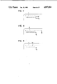
- FIGS. 3 through 6 are illustrative views of the display screen
- FIGS. 7 to 11 are illustrative views of the display screen in a prior art device
- FIGS. 12(1) and 12(2) are flow charts showing the control operation for the line format setting mode.
- FIGS. 13 and 14 are illustrative views of the display screen of the word processor embodying the invention.
- FIG. 1 shows the block diagram of the word processor embodying the invention, wherein a keyboard 10 includes a character keys section 11 consisting of alpha and numeric keys and various symbol keys, and a function keys section 12 including a space key, back space key, return key, cursor move keys, margin set keys, space keys, escape keys and so on.
- a keyboard 10 includes a character keys section 11 consisting of alpha and numeric keys and various symbol keys, and a function keys section 12 including a space key, back space key, return key, cursor move keys, margin set keys, space keys, escape keys and so on.
- the key code corresponding to the key strokes is sent from the keyboard 10 to a CPU (Central Processing Unit) 20 through operation of these keys.
- a CPU Central Processing Unit
- the CPU 20 executes operations required for processing input and output character and similar data and editing procedure, in accordance with program data stored in a ROM (Read Only Memory) 30. It also places a text cursor and a scale cursor on the same column on a CRT (Cathode Ray Tube) 70 which serves as a display medium. The CPU 20 further operates to send printing-head move signals in response to the character width and type selection signals dependent on the characters to a printing mechanism 80.
- the CPU 20, ROM 30, RAM (Random Access Memory) 40, video RAM 50, CRT controller 60 and printing mechanism 80 are all interconnected via a common bus for transfer of control signals, data signals and address signals.
- the ROM 30 contains character spacing data of each character, other than the program data mentioned above.
- the RAM 40 is provided with a text memory 41 into which the data such as characters and symbols to be entered from the keyboard 10 is stored, a text cursor pointer 42 which stores the data indicating the position of the text cursor (line and column), a scale memory 43, a total character spacing counter 44, a scale move counter 45 and a scale cursor column counter 46.
- the total character spacing counter 43 retains the value of total character spacing of the characters entered to the left side of the text cursor on the line where it exists.
- There is a scale S as illustrated in FIG. 3 indicating the number of columns on top area of the CRT 70, with the scale cursor SK shown under the scale S which is movable horizontally along the scale S to indicate the data printing position (column).
- the scale S is, on display, horizontally moved in dependence on the spacing of the characters to be entered as described later in more detail.
- the number of columns through which the scale S has been moved with respect to the text display is stored in the scale move counter 45.
- the column on which the scale cursor SK is positioned is written into the scale cursor column counter 46.
- the text cursor pointer 42 and the scale cursor column counter 46 keep in memory the addresses of the text cursor TK and the scale cursor SK stored in the video RAM.
- the scale memory 43 retains data for dots, figures and margin marks (triangular shape) forming the scale S.
- the video RAM 50 is a display buffer which temporarily stores the data for one screen to be displayed on the CRT 70 and its memory address one by one corresponds to the display address on the display screen of the CRT 70.
- the CRT controller 60 is a unit to display alphabetical or other characters on the CRT 70 which is provided with a character generator retaining the type font (type pattern) and is also connected to the video RAM 50.
- the CRT controller 60 displays characters at an equal spacing (standard spacing) on the CRT 70.
- the data sent from the keyboard 10 is written into the text memory 41 as well as into the specified address of the video RAM 50 by means of the CPU 20.
- the CRT controller 60 immediately reads the written data from the video RAM 50 and displays the corresponding type font within the character generator on the CRT 70, while operating to indicate the text cursor TK on the column next to the column on which the character is shown.
- the printing mechanism 80 has a printing head, not shown, horizontally movable in accordance with printerhead moving signals sent from the CPU 20 depending upon the character spacing. It is possible to use, as printing mechanism, thermal printer, wire-dot printer and type-wheel printer.
- a left margin LM and a right margin RM are placed at predetermined positions of the scale S on the screen using the margin move keys.
- the left margin LM is on column 22 of the scale S
- the screen then scrolls to the left by 20 columns.
- the printing spacing can be arbitrarily selected on the scale S between the both margins LM and RM, it is preferable to set it within 60% of the number of columns with in the text area.
- the text cursor TK is positioned on column 23 on the first line of the text area as shown in FIG. 3.
- the scale cursor SK is placed on column 23 of the scale S and is in alignment with the text cursor TK.
- the corresponding character code is then stored in the text memory and also in the address specified by the text cursor TK within the video RAM 50, so that the character "W” comes up on line 1, column 23 of the text area on the CRT 70.
- the standard spacing is assumed at 10 pitch and the characters are all displayed on the screen at equal spacing of 10 pitch.
- the text cursor TK and the scale cursor SK are both moved to column 24 on the same line.
- step 100 the character spacing data (printing spacing) for the character "W" which is stored in the ROM 30 is read out to be added to the data from the total character spacing counter 44. Because the data within the total character spacing counter 44 has been 0 in this example, the resultant value in the total character spacing counter 44 is 16 pitch (equal to the spacing of the "W"). Such data in the total character counter 44 is cleared upon change of the line.
- the current column Ct (column 24) of the text cursor TK is calculated from the data within the text cursor pointer 42.
- step 120 the total character spacing data is taken from the total character spacing counter 44. This value (16 pitch) is divided by the standard spacing (10 pitch) to provide a quotient (1, decimal places cur away).
- the current column (24) of the scale cursor SK is given by adding this quotient plus 1 to the column (22) on which the left margin LM currently exists.
- the scale cursor SK is then moved to this column. Because the scale S by no means scrolls horizontally relative to the text area at this time, the current position of the scale cursor SK becomes a virtual column Cs.
- the step 130 is to compare the current column Ct (column 24) of the text cursor TK given in step 110 with the virtual column Cs (column 24) of the scale cursor SK given in step 120.
- step 140 the scale S is displayed on the screen of CRT 70 without any movement and 0 is stored in the scale move counter 45, because the scale S is not moved.
- the character code is stored in the address specified by the text cursor in the video RAM 50 in the manner described above, while on the screen of CRT 70, this "W” is shown on the same line but on the column next (24) to the "W” displayed previously.
- the text cursor TK is displayed on the same line, column 25 (FIG. 5).
- the character spacing data for the character "W" stored in the ROM 30 is read out and is added to the data from the total spacing counter 44 (16 pitch). The value within the total spacing counter is now 32 pitch.
- step 110 the current column Ct (column 25) of the text cursor TK is calculated from the data within the text cursor pointer 42.
- step 120 the total spacing data is taken from the total character spacing counter 44. This value (32 pitch) is divided by the standard spacing (10 pitch) to provide a quotient (3).
- the current column (26) of the scale cursor SK is given by adding the quotient plus 1 to the current on which the left margin LM exists. The scale cursor SK is thus displayed on column 26. Because the scale S does not move at this time, the current column of the scale cursor SK is a virtual column Cs.
- the step 130 is to compare the current column Ct (25) of the text cursor TK given in step 110 with the virtual column Cs (26) of the scale cursor SK given in step 120. With the result of Ct ⁇ Cs, the step 160 is now entered.
- step 160 the data within the video RAM 50 is re-written so that the scale S on the CRT 70 screen is moved to the left by the difference between the virtual column Cs of the scale cursor SK and the current column Ct of the text cursor TK.
- the scale cursor SK and the text cursor TK are thus brought into alignment on the screen as illustrated in FIG. 5.
- the scale move counter 45 receives the data "-1 column" which indicates that the scale S has been moved to the left by one column.
- the character code is written in the address specified by the text cursor TK in the video RAM 50, while on the CRT 70 screen, this "i” is shown on the same line but on the column next (25) to the "W” displayed previously (FIG. 6).
- the text cursor TK is displayed on the same line, column 26.
- step 100 the character spacing data (6 pitch) for the character i stored in the ROM 30 is read out and is added to the data (32 pitch) from the total spacing counter 44. The value within the total spacing counter is now 38 pitch.
- step 110 the current column Ct (column 26) of the text cursor TK is calculated from the data within the text cursor pointer 42.
- step 110 the total spacing data is taken from the total character spacing counter 44. This value (38 pitch) is divided by the standard spacing (10 pitch) to provide a quotient (3).
- the current column (26) of the scale cursor SK is given by adding the quotient plus 1 to the current column on which the left margin LM exists.
- the scale cursor SK is thus displayed on column 26.
- the data (-1 column) is taken from the scale move counter 45 in step 120. This value is added to the current column (26) mentioned above to calculate the virtual column Cs (25) of the scale cursor SK.
- the step 130 is to compare the current column Ct (26) of the text cursor TK given in step 110 with the virtual column Cs (25) of the scale cursor SK given in step 120. With the result of Ct Cs, the step 150 is now entered.
- step 150 the data within the video RAM 50 is re-written so that the scale S on the CRT 70 screen is moved to the right by a difference (only 1 column) between the virtual column Cs of the scale cursor SK and the current column Ct of the text cursor TK.
- the scale cursor SK and the text cursor TK are thus brought into alignment on the screen as illustrated in FIG. 6.
- the scale move counter 45 receives the adding data "1column" which indicates that the scale S has been moved to the right by one column, rendering the counter data 0 column.
- the scale cursor SK is in this example displayed on the current column Ct immediately after the current column Ct is calculated in step 110. Instead, the scale cursor SK can be displayed on the virtual column Cs upon completion of the scale movement in step 140, step 150 and step 160.
- scale movement is controlled so that the column on the data entry position coincides with the column on the scale which indicates the position on a printing medium corresponding to the data entry position on a display medium. This allows operators to easily grasp the actual printing position on the printing medium while entering data.
- FIG. 12 shows a flow chart of another program embodying the invention. This program is for changing a format during editing a text.
- this line-format setting mode is entered, the text area 231 of the screen 203 is brought to standstill, while the scale line 233 in the format area 232 is controlled to be freely movable.
- the CPU 20 starts key scanning in S203 and, when it determines in S204 that the left or right scale cursor move key on the keyboard 10 has been pressed, it moves the pointer of the scale cursor 234 within the RAM 40, as indicated in S205.
- the CPU 20 determines in S204 that the scale cursor move key has not been depressed, it examines if any set key to be described below has been depressed down in S209. When there is some set key depressed, the form corresponding to the operation of the set key is set in S210, then returning to S203.
- the left margin set key is found to be down in S209, the left margin 235 is set on the CRT 70, while when the right margin set key is found to be down, the right margin 236 is set likewise. If the left and right margins 235 and 236 are already set, the set margins are canceled to enter the latest ones in the ram 40.
- the tab 237 and/or the decimal tab 238 are set when the keys therefor are found to be down respectively. Also, the hot zone is set if the key therefor is found to be down and the line spacing is altered if the key therefor is found to be down. Furthermore, the pitch and scale line are altered when the key therefor is found to be down, the tab 237 at the cursor position is cleared and all the tabs 237 and 238 are cleared if the keys therefor are found to be down, respectively.
- step S213 determines that the page key depressed in S201 as above has been depressed again, the line format is registered and the line format register mode is then cleared in S214.
- the next S215 allows the pertaining text to be reformed according to the line format registered.
- the scale cursor 234 moves to the position on scale line 233 which corresponds to the text cursor 239 in the text screen 231. This finally allows escaping to another routine. At this time, the text screen 231 as well as the scale line 233 horizontally scroll as required.
- the text screen 231 is kept at standstill even if the scale cursor 234 is moved.
- This provides two effects, one being that the operator suffers a minimum eyestrain because of reduced flicker of screen and the other being that the processing time with the internal circuit is shortened to allow the next keystroke to be entered without an undersirable lagtime, resulting in a shorter time for editing the text or the like in memory.
Abstract
Description
Claims (6)
Applications Claiming Priority (4)
| Application Number | Priority Date | Filing Date | Title |
|---|---|---|---|
| JP61165777A JPS6320663A (en) | 1986-07-15 | 1986-07-15 | Word processor |
| JP61-165777 | 1986-07-15 | ||
| JP61166273A JPS6321173A (en) | 1986-07-15 | 1986-07-15 | Information processor |
| JP61-166273 | 1986-07-15 |
Publications (1)
| Publication Number | Publication Date |
|---|---|
| US4897804A true US4897804A (en) | 1990-01-30 |
Family
ID=26490384
Family Applications (1)
| Application Number | Title | Priority Date | Filing Date |
|---|---|---|---|
| US07/073,971 Expired - Fee Related US4897804A (en) | 1986-07-15 | 1987-07-15 | Data processing device with screen seperated into line format area and data display area |
Country Status (3)
| Country | Link |
|---|---|
| US (1) | US4897804A (en) |
| EP (1) | EP0259957B1 (en) |
| DE (1) | DE3783978T2 (en) |
Cited By (7)
| Publication number | Priority date | Publication date | Assignee | Title |
|---|---|---|---|---|
| US5151075A (en) * | 1990-11-05 | 1992-09-29 | J & L Industries, Inc. | Carton folding apparatus |
| US5363480A (en) * | 1990-02-02 | 1994-11-08 | Brother Kogyo Kabushiki Kaisha | Layout display control system for document processing apparatus |
| US5548700A (en) * | 1989-12-29 | 1996-08-20 | Xerox Corporation | Editing text in an image |
| US5627948A (en) * | 1984-03-09 | 1997-05-06 | Canon Kabushiki Kaisha | Information processing apparatus and method for displaying format information for a line to which a cursor is shifted by scrolling in a format display area |
| US5734761A (en) * | 1994-06-30 | 1998-03-31 | Xerox Corporation | Editing scanned document images using simple interpretations |
| US5801677A (en) * | 1993-09-30 | 1998-09-01 | Fujitsu Limited | Shared document display system |
| US20160357710A1 (en) * | 2015-06-05 | 2016-12-08 | Alpine Electronics, Inc. | Text display control apparatus and method for controlling text to be displayed |
Families Citing this family (2)
| Publication number | Priority date | Publication date | Assignee | Title |
|---|---|---|---|---|
| JPS63155257A (en) * | 1986-12-18 | 1988-06-28 | Brother Ind Ltd | Word processor |
| JPH0228757A (en) * | 1988-07-18 | 1990-01-30 | Brother Ind Ltd | Document generating device |
Citations (6)
| Publication number | Priority date | Publication date | Assignee | Title |
|---|---|---|---|---|
| US3648271A (en) * | 1970-03-02 | 1972-03-07 | Ibm | Visual editing system incorporating selectable letter spacing display and associated scale display |
| EP0066674A1 (en) * | 1981-05-18 | 1982-12-15 | International Business Machines Corporation | Method for processing information including text fields together with character and arithmetic fields |
| US4370645A (en) * | 1981-06-16 | 1983-01-25 | International Business Machines Corporation | Ghost cursor in display all codes mode |
| US4495491A (en) * | 1979-09-28 | 1985-01-22 | Siemens Aktiengesellschaft | Method for highlighting of a region on a display screen |
| US4648047A (en) * | 1984-10-24 | 1987-03-03 | International Business Machines Corporation | Interactive operator selection of alternative implementations of printer functions |
| US4677571A (en) * | 1985-02-08 | 1987-06-30 | Rise Technology Inc. | Electronic publishing |
Family Cites Families (1)
| Publication number | Priority date | Publication date | Assignee | Title |
|---|---|---|---|---|
| EP0661674A1 (en) * | 1993-12-28 | 1995-07-05 | Eastman Kodak Company | Method and apparatus for point-of-sale digital half-toning image verification |
-
1987
- 1987-07-14 DE DE8787306213T patent/DE3783978T2/en not_active Expired - Fee Related
- 1987-07-14 EP EP87306213A patent/EP0259957B1/en not_active Expired - Lifetime
- 1987-07-15 US US07/073,971 patent/US4897804A/en not_active Expired - Fee Related
Patent Citations (6)
| Publication number | Priority date | Publication date | Assignee | Title |
|---|---|---|---|---|
| US3648271A (en) * | 1970-03-02 | 1972-03-07 | Ibm | Visual editing system incorporating selectable letter spacing display and associated scale display |
| US4495491A (en) * | 1979-09-28 | 1985-01-22 | Siemens Aktiengesellschaft | Method for highlighting of a region on a display screen |
| EP0066674A1 (en) * | 1981-05-18 | 1982-12-15 | International Business Machines Corporation | Method for processing information including text fields together with character and arithmetic fields |
| US4370645A (en) * | 1981-06-16 | 1983-01-25 | International Business Machines Corporation | Ghost cursor in display all codes mode |
| US4648047A (en) * | 1984-10-24 | 1987-03-03 | International Business Machines Corporation | Interactive operator selection of alternative implementations of printer functions |
| US4677571A (en) * | 1985-02-08 | 1987-06-30 | Rise Technology Inc. | Electronic publishing |
Non-Patent Citations (1)
| Title |
|---|
| IBM Technical Disclosure Bulletin, vol. 27, No. 11 Apr. 1985. * |
Cited By (8)
| Publication number | Priority date | Publication date | Assignee | Title |
|---|---|---|---|---|
| US5627948A (en) * | 1984-03-09 | 1997-05-06 | Canon Kabushiki Kaisha | Information processing apparatus and method for displaying format information for a line to which a cursor is shifted by scrolling in a format display area |
| US5548700A (en) * | 1989-12-29 | 1996-08-20 | Xerox Corporation | Editing text in an image |
| US5363480A (en) * | 1990-02-02 | 1994-11-08 | Brother Kogyo Kabushiki Kaisha | Layout display control system for document processing apparatus |
| US5151075A (en) * | 1990-11-05 | 1992-09-29 | J & L Industries, Inc. | Carton folding apparatus |
| US5801677A (en) * | 1993-09-30 | 1998-09-01 | Fujitsu Limited | Shared document display system |
| US5734761A (en) * | 1994-06-30 | 1998-03-31 | Xerox Corporation | Editing scanned document images using simple interpretations |
| US20160357710A1 (en) * | 2015-06-05 | 2016-12-08 | Alpine Electronics, Inc. | Text display control apparatus and method for controlling text to be displayed |
| US10127193B2 (en) * | 2015-06-05 | 2018-11-13 | Alpine Electronics, Inc. | Text display control apparatus and method for controlling text to be displayed |
Also Published As
| Publication number | Publication date |
|---|---|
| EP0259957B1 (en) | 1993-02-03 |
| EP0259957A2 (en) | 1988-03-16 |
| DE3783978T2 (en) | 1993-06-03 |
| EP0259957A3 (en) | 1989-06-21 |
| DE3783978D1 (en) | 1993-03-18 |
Similar Documents
| Publication | Publication Date | Title |
|---|---|---|
| US4812832A (en) | Input control device | |
| GB1296175A (en) | ||
| GB1296174A (en) | ||
| EP0009536B1 (en) | Data entry apparatus with dual-mode tabbing function selectable from keyboard | |
| US4897804A (en) | Data processing device with screen seperated into line format area and data display area | |
| US5278952A (en) | Document processing apparatus having layout display control system | |
| EP0273764B1 (en) | Text processing system | |
| JPS6321173A (en) | Information processor | |
| JPH074956B2 (en) | Character processor | |
| JP3077777B2 (en) | Document processing device | |
| JPH0823744B2 (en) | Character string processor | |
| JP2555557B2 (en) | Character processor | |
| JPS6362004B2 (en) | ||
| JPS60239861A (en) | Arabic word processor system | |
| JP2837497B2 (en) | Output control device and output control method | |
| JP2573183B2 (en) | Kana-Kanji conversion device | |
| JP2555558B2 (en) | Character processor | |
| JP2555556B2 (en) | Character processor | |
| JPS625292A (en) | Charactor input unit | |
| JPS6214192A (en) | Wordprocessor | |
| JP2592840B2 (en) | Character processor | |
| JPH06222895A (en) | Print format preparing device | |
| JPS63291089A (en) | Character processor | |
| JPS6320665A (en) | Input device | |
| JPH0463785B2 (en) |
Legal Events
| Date | Code | Title | Description |
|---|---|---|---|
| AS | Assignment |
Owner name: BROTHER KOGYO KABUSHIKI KAISHA, 35, HORITA-DORI 9- Free format text: ASSIGNMENT OF ASSIGNORS INTEREST.;ASSIGNORS:KAWAKAMI, YASUSHI;OBATA, FUKUE;MAKIHARA, KAYOKO;AND OTHERS;REEL/FRAME:004775/0989 Effective date: 19870709 Owner name: BROTHER KOGYO KABUSHIKI KAISHA,JAPAN Free format text: ASSIGNMENT OF ASSIGNORS INTEREST;ASSIGNORS:KAWAKAMI, YASUSHI;OBATA, FUKUE;MAKIHARA, KAYOKO;AND OTHERS;REEL/FRAME:004775/0989 Effective date: 19870709 |
|
| FEPP | Fee payment procedure |
Free format text: PAYOR NUMBER ASSIGNED (ORIGINAL EVENT CODE: ASPN); ENTITY STATUS OF PATENT OWNER: LARGE ENTITY |
|
| FEPP | Fee payment procedure |
Free format text: PAYOR NUMBER ASSIGNED (ORIGINAL EVENT CODE: ASPN); ENTITY STATUS OF PATENT OWNER: LARGE ENTITY Free format text: PAYER NUMBER DE-ASSIGNED (ORIGINAL EVENT CODE: RMPN); ENTITY STATUS OF PATENT OWNER: LARGE ENTITY |
|
| FEPP | Fee payment procedure |
Free format text: PAYOR NUMBER ASSIGNED (ORIGINAL EVENT CODE: ASPN); ENTITY STATUS OF PATENT OWNER: LARGE ENTITY Free format text: PAYER NUMBER DE-ASSIGNED (ORIGINAL EVENT CODE: RMPN); ENTITY STATUS OF PATENT OWNER: LARGE ENTITY |
|
| FPAY | Fee payment |
Year of fee payment: 4 |
|
| REMI | Maintenance fee reminder mailed | ||
| LAPS | Lapse for failure to pay maintenance fees | ||
| FP | Lapsed due to failure to pay maintenance fee |
Effective date: 19980204 |
|
| STCH | Information on status: patent discontinuation |
Free format text: PATENT EXPIRED DUE TO NONPAYMENT OF MAINTENANCE FEES UNDER 37 CFR 1.362 |