US4726014A - Cellular mobile radio service telephone system - Google Patents
Cellular mobile radio service telephone system Download PDFInfo
- Publication number
- US4726014A US4726014A US06/780,493 US78049385A US4726014A US 4726014 A US4726014 A US 4726014A US 78049385 A US78049385 A US 78049385A US 4726014 A US4726014 A US 4726014A
- Authority
- US
- United States
- Prior art keywords
- switch group
- remote switch
- network control
- ncs
- coupled
- Prior art date
- Legal status (The legal status is an assumption and is not a legal conclusion. Google has not performed a legal analysis and makes no representation as to the accuracy of the status listed.)
- Expired - Fee Related
Links
Images


Classifications
-
- H—ELECTRICITY
- H04—ELECTRIC COMMUNICATION TECHNIQUE
- H04W—WIRELESS COMMUNICATION NETWORKS
- H04W88/00—Devices specially adapted for wireless communication networks, e.g. terminals, base stations or access point devices
- H04W88/14—Backbone network devices
Definitions
- This invention pertains to an improved type of mobile telephone system, in general, and to an improved cellular mobile radio telephone system, in particular.
- CMRS Cellular Mobile Radio Service
- the radiotelephone units utilize radio frequency to communicate with low power, limited radiation base transceivers in a cellular pattern making it necessary for the system to locate each mobile unit and follow it enroute by "handing off" in-progress calls between cells.
- the low power, limited radiation elements of CMRS systems allow a unique frequency distribution and reuse scheme to provide sufficient channels to serve any number of subscribers (i.e. 100,000).
- the mobile radios are intelligent units; that is, they contain a microprocessor equivalent logic element. They store certain permanent information (i.e. unit manufacturer's serial number), semi-permanent information (i.e. registration memory), temporary memory containing individual call data and timers, etc.
- permanent information i.e. unit manufacturer's serial number
- semi-permanent information i.e. registration memory
- temporary memory containing individual call data and timers, etc.
- each unit can access 666 radio channels but must manually or automatically select either an upper band of 333 of a lower band. (Current FCC rules allocate the upper band to a non-wire line RCC and the lower band to a telco owned RCC).
- the base radio "stations" are located in a pattern of "cells" of from about 1 mile to up to 10 miles across which form a patchwork coverage of the desired area.
- Each cell radio operates with several assigned channels selected so that they do not interfere with channels of nearby cells. Due to the restricted power and range of cell radio transmitters, each set of cell frequencies may be reused in a cell only a few miles away.
- CMRS Advanced Mobile Phone Service
- AMPS Advanced Mobile Phone Service
- a cellular mobile radio system having "switched-through control.” More specifically, the switching matrix used for switching of the signals representing the audio portion of telephone calls is also used to selectively switch the various control signals associated with processing of telephone calls.
- control signals between cell site transceivers and the network control system are switched through the switching matrix and share the standard transmission facilities used for the audio aspect of telephone calls.
- multiple NCS's may be used to expand the size of the CMRS system by exchanging control information via paths established through the respective switching matrices and the standard transmission facilities interconnecting the NCS's.
- a CMRS system may be provided with a remote switch group (RSG) arrangement having its own switching matrix and wherein the RSG arrangements operate under its own microprocessor control with sufficient intelligence to switch port-to-port traffic and perform routine tasks under NCS direction via the NCS switching matrix standard transmission facilities and the RSG switching matrix.
- RSG remote switch group
- a high degree of reliability may be provided by the use of individually redundant cells coupled to a NCS switching matrix which in turn couples to a common pool of control elements.
- control signals for a plurality of transceivers are statistically multiplied together to form a concentrated byte interleaved data stream.
- a plurality of concentrated data streams are reformatted in packetized form into a more highly concentrated data stream which is presented to the NCS central processor complex.
- FIG. 1 illustrates a CMRS system
- FIG. 2 illustrates in greater detail the NCS and one cell site of the CMRS system of FIG. 1;
- FIGS. 3, 4 and 5 which arranged as shown in FIG. 6 illustrate the control paths of FIG. 2;
- FIG. 7 illustrates a control concentrator in greater detail
- FIG. 8 illustrates a CMRS system utilizing remote switch groups
- FIG. 9 illustrates one arrangement for providing control of the remote switch groups by a NCS
- FIG. 10 illustrates a second arrangement for providing control of the remote switch groups by an NCS
- FIG. 11 illustrates a CMRS system utilizing multiple NCS's
- FIG. 12 illustrates a control path arrangement for the system of FIG. 10.
- the CMRS system of FIG. 1 illustrates an arrangement having 7 cells each having voice and data connections to a network control system (NCS).
- NCS network control system
- the NCS is in turn connected to the telephone network.
- Each cell uses one or more of 21 channels as set-up channels to broadcast continuously certain routine or overhead information which permits the mobiles to select the nearest cell, identify the system, etc.
- the CMRS system continuously transmits digital data on each cell set-up channel including such information as the CMRS system identification, overload control ("line load” control), synchronizing bits, busy-idle status of reverse signaling channel and signaling channel numbers used in this location.
- HMU Home Mobile Unit
- the system would try to page it by sending out the car directory number of paging (setup) channels. Receiving no response, the NCS can return such an indication to the calling subscriber in the form of an announcement. (If the called mobile unit is turned on and answers the page, the mobile will be "rung” and the caller will receive ringback tone indicating that the mobile is in the area and turned on).
- the mobile unit first turns on his radiotelephone, it first scans all set-up channels. The unit would verify that it was in its home area dn the paging (or set-up) channels and voice channels used in this complex would be identified to the mobile unit.
- the mobile unit would then scan the identified set-up channel and select and tune to the strongest one, presumably the nearest cell transmitter. "Busy-idle" bits inform the mobile unit the status of the reverse (mobile to base) signaling channel to prevent simultaneous seizure by more than one mobile unit. (There are also other handshake and timing checks to guard against "collisions” .)
- the mobile unit now automatically "reports in” to the system and sends its unit serial number, its assigned telephone number (7 to 10 digits), its power level, etc. and turns off its transmitter, continuing to monitor the selected set-up channel for a page.
- the NCS "registers" the mobile unit as either a home or foreign unit. Depending upon system procedures, the registration could verify that service has not been discontinued or is not on a "hot list” relating to unauthorized use or stolen units.
- the NCS directs the paging (7 digit number) to be sent on the appropriate paging channels.
- the mobile receives the page and detects that it coincices with its assigned telephone number. It acknowledges on a selected set-up channel by sending back its identification number.
- the NCS selects a voice channel and advises the mobile to switch to that channel, abandoning the set-up channel.
- the mobile acknowledges that he is now tuned to the selected voice channel by an in-band SAT (supervisory) tone.
- the NCS directs the base RF equipment to send an alterting data burst over the voice channel and the mobile begins the audible alert (ringing).
- the mobile returns an out of band signaling tone acknowledging that it is in a ringing process and the NCS returns ringback to the calling party. When the mobile is answered, the signaling tone is removed and the call cut through.
- the mobile goes "off hook” and scans and selects the strongest set-up channel.
- the mobile sends identification and the dialed digits to the NCS.
- the mobile unit then waits for a voice channel assignment and, by supervisory and signaling tones associated with the assigned channel, provides the necessary answer supervision, disconnect, etc.
- the set-up channels are used only very briefly during the identification, location and voice channel assignment process. Since this is a big "party line” or common channel, occupancy must be limited.
- CMRS CMRS CMRS CMRS CMRS CMRS CMRS CMRS CMRS CMRS CMRS CMRS CMRS CMRS CMRS CMRS CMRS CMRS CMRS CMRS CMRS CMRS CMRS CMRS CMRS CMRS CMRS CMRS CMRS CMRS CMRS CMRS CMRS CMRS CMRS CMRS CMRS .
- the NCS decides when a "hand-off" to another cell is advisable based upon relative signal strength, next cell congestion, etc.
- the NCS enables the new cell and selects a new channel.
- a signal to switch to a new channel is sent to the mobile over the current serving channel by means of a very short digital burst which is not detectable by the listener.
- the mobile sends a disconnect signal tone, turns off its transmitter, re-tunes to the new channel and sends supervisory tone.
- the NCS recognizes the successful hand-off and
- the mobile is a "roamer” from another CMRS system (though perhaps serving the same area), it will be designated a Foreign Mobile Unit (FMU) in this area. Operation is almost identical except that local calls from the FMU are probably billable and must be recorded with calling details.
- FMU Foreign Mobile Unit
- the block diagram of FIG. 2 illustrates the NCS and one cell site of the system of FIG. 1 in greater detail.
- the NCS equipment includes the commercially available ITT System 1210 hardware and software.
- the basic configuration shown in FIG. 2 includes the ITT System 1210 processor as network control; direct memory access (DMA) equipment; switch groups; a line switch to accomodate service circuits such as DTMFR, MFR conference circuits, line interface (cc) and operator interface (OPI); various I/O peripherals such as TTY, magnetic tape (MT) and terminals (CRT); trunks; and a system test frame, tone and recorded announcement source, which are not shown in FIG. 1.
- the NCS further includes a pool of control concentrators coupled between the switch group matrix and the DMA via channel units, modems if necessary, and signal conditioning circuits.
- the NCS is coupled to the cell site via transmission facilities which in the example shown are T1 spans.
- the cell site includes a plurality of specialized use transceivers including set-up radio transceiver, data channel transceivers, voice channel transceivers, locating radio receivers, paging transmitters, and base radio test equipment.
- each of the transceivers, receivers or transmitters may be of type as described in the aforementioned Bell System Technical Journal reference or may be of any other types including types having microprocessor control.
- Each transceiver, receiver, transmitter has bidirectional control ports for the exchange of control information with the NCS.
- the voice channel transceivers and the base radio test equipment have a bidirectional audio signal port; the data channel transceiver has bidirectional data ports.
- the audio signal ports are coupled via a 4-wire voice frequency facility to channel units contained in a channel bank which is in turn coupled to the T1 span and thus to the switch matrix in the NCS.
- Each bidirectional control port is duplicated and is coupled to the statistical multiplexers A and B.
- the statistical multiplexers are in turn coupled to channel units in the channel banks which in turn are coupled to the T1 span and thus to the switch matrix in the NCS. It should be noted that redundancy is provided for reliability purposes.
- the statistical multiplexers shown in FIG. 2 and also in the other figures to be described below may be of the commercially available types described by Harry J. Hindin in “controlling data communications: statistical multiplexer move in”, Electronics, July 28, 1981, p. 141-148 and by J. H. Scharen-Guivel and A. A. Carlson in “A buyers guide to todays versatile statistical multiplexers", Data Communications, March, 1982, pp. 97-126.
- a statistical multiplexer is utilized to multiplex a number of terminals to a data link.
- Conventional time division multiplexers of either the bit- or the character-interleaving type assign dedicated time slots to each terminal. With statistical multiplexing the available bandwidth of the trunk is allocated dynamically.
- the statistical multiplexer also performs demultiplexing operations for coupling information from the data link to the terminals by using the inverse of the process described above.
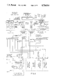
- FIG. 6 illustrates the NCS (FIG. 5) coupled via analog transmission facility (FIG. 3) to one cell and coupled via digital transmission facility (FIG. 4) to another cell.
- each of the cells is shown as having three voice channel transceivers 31, 32, 33 and one set up transceiver 34.
- Each voice channel transceiver has a pair of duplicated control ports control A, control B, respectively coupled to a pair of statistical multiplexers 35, 36.
- the data link side of each statistical multiplexer 35, 36 utilizes signals that are compatible to one or more of RS 232/422, 423 signaling classes.
- a standard commercially available modem 37 is used to convert the signals between the RS 232/422, 423 signaling classes to inband audio tones on an analog transmission facility 38 which is terminated at the NCS via a channel unit contained in channel bank 51.
- the data link side of the statistical multiplexer, 35, 36 are terminated on commercially available data type channel units in channel banks 41, 42 which are coupled to the digital transmission facility 43 which is terminated at the NCS.
- each cell includes the redundant pairs of statistical multiplexers 35, 36.
- N redundant pairs there are 2N appearances at the left side of the digital matrix as shown in FIG. 6.
- a plurality of channel banks 54 are coupled to the terminals at the right side of the digital matrix 52.
- the channel banks include data channel units corresponding to the data channel units utilized in the channel banks of FIG. 4 and voice units connected to modems 55 as in FIG. 3.
- the data channel units and modems 55 are coupled to ports on a plurality of control concentrators 56 which are in turn coupled to the direct memory access DMA of the central processing unit CPU.
- the communications from a plurality of transceivers is placed on the facility toward the control concentrators in a byte interleaved basis by the statistical multiplexers. Communications from a plurality of statistical multiplexers are byte deleaved and packetized by the control concentrator and serially presented to the DMA via signal conditioning circuits 59.
- the control concentrators 56 each serve to reformat and multiplex the communications from a plurality of statistical multiplexers thereby providing another level of multiplexing and concentration of control.
- Each control concentrator 56 shown in greater detail in FIG. 7 includes a microprocessor 71 having I/O ports, some of which are coupled to the statistical multiplexers via the matrix and one or a few of which are connected to the DMA.
- a random area memory 72 is coupled to the microprocessor 71 as are various peripherals such as a disk unit and a tape unit.
- the memory 72 is a 512K bytes of 32 byte memory.
- the number of control concentrators required for a system having N pairs of statistical multiplexers is M+X where X is the number of spare units required to achieve the desired availability.
- FIG. 8 illustrates another advantageous configuration of a CMRS system wherein portions of the switching matrix are remoted from the NCS.
- This Remote Switch Group (RSG) arrangement operates under its own microprocessor control with sufficient intelligence to switch port-to-port traffic and perform routine tasks under hose NCS direction.
- RSG Remote Switch Group
- the RSG is a remote (from NCS) switching node within the cellular network, and consists in its most basic configuration of two or more standard ITT 1210 switch groups, a digital tone supply, a Stratum III synchronizable clock, and digital or analog trunks as required (see FIG. 10).
- Service circuits (MFR, conference circuits, etc.) and recorded announcement sources reside in the host NCS and are assigned dedicated channels in the NSC-to-RSG link route. Service circuits and announcement machines may be added in the RSG when its size and common traffic interest with the NCS make this desirable.
- the synchronizable clock is required to keep the digital RSG matrix synchronized with the NCS and digital links.
- Two of the RSG switch groups are equipped with special interfaces to the digital tone supply (TAG) and synch clock for maintenance and alarm control access by the NCS system controller.
- TAG digital tone supply
- synch clock for maintenance and alarm control access by the NCS system controller.
- the NCS controller data structure is arranged to provide separate translation domains for each RSG. This allows individual routing patters for a given called number that are unique to that translation domain. Multiple translation domains per RSG (or NCS) can also be assigned.
- the links consist of standard T1 span lines (or T1 compatible facilities). Digital channel banks with individual channel Drop/Insert ports at each end are used for control communication between the NCS system controller and the RSG switch group controllers. Two channels per remote switch group controller (on separate T1 lines for reliability) are used, and the number of channels droped/inserted thus depends on the number of individual switch groups in the RSG.
- the switched through control concept which was applied to the arrangements of FIGS. 1-7 can further advantageously be used for the arrangement of FIG. 8 as shown in FIG. 10.
- the control between the NCS and individual RSG's is accomplished by establishing a path from the DMA of the NCS through the NCS's matrix over transmission facility to the RSG through its matrix to the switch group (SWG) control of the RSG. Two channels per RSG controller are used for reliability.
- a large cellular geographic area may be served by multiple NCS's each of which is remote from the others as shown in FIG. 11.
- the switched through control concept may still further advantageously be applied to such an arrangement as shown in FIG. 12 wherein a control path may be established between two NCS's X, Y be establishing a path through the matrix of NCS X, over transmission facility to the other NCS, Y through its matrix and control concentrator.
Abstract
Description
Claims (5)
Priority Applications (1)
| Application Number | Priority Date | Filing Date | Title |
|---|---|---|---|
| US06/780,493 US4726014A (en) | 1983-01-11 | 1985-09-26 | Cellular mobile radio service telephone system |
Applications Claiming Priority (2)
| Application Number | Priority Date | Filing Date | Title |
|---|---|---|---|
| US06/457,155 US4562572A (en) | 1983-01-11 | 1983-01-11 | Cellular mobile radio service telephone system |
| US06/780,493 US4726014A (en) | 1983-01-11 | 1985-09-26 | Cellular mobile radio service telephone system |
Related Parent Applications (1)
| Application Number | Title | Priority Date | Filing Date |
|---|---|---|---|
| US06/457,155 Division US4562572A (en) | 1983-01-11 | 1983-01-11 | Cellular mobile radio service telephone system |
Publications (1)
| Publication Number | Publication Date |
|---|---|
| US4726014A true US4726014A (en) | 1988-02-16 |
Family
ID=27038502
Family Applications (1)
| Application Number | Title | Priority Date | Filing Date |
|---|---|---|---|
| US06/780,493 Expired - Fee Related US4726014A (en) | 1983-01-11 | 1985-09-26 | Cellular mobile radio service telephone system |
Country Status (1)
| Country | Link |
|---|---|
| US (1) | US4726014A (en) |
Cited By (43)
| Publication number | Priority date | Publication date | Assignee | Title |
|---|---|---|---|---|
| US4881271A (en) * | 1987-03-20 | 1989-11-14 | Hitachi, Ltd. | Portable wireless communication systems |
| WO1990004298A1 (en) * | 1988-10-05 | 1990-04-19 | Precision Software Incorporated | Integrated telecommunication system with improved digital voice response |
| US5034993A (en) * | 1989-03-15 | 1991-07-23 | Motorola, Inc. | Method for allocating communication resources among RF communications systems |
| US5040195A (en) * | 1988-12-20 | 1991-08-13 | Sanyo Electric Co., Ltd. | Synchronization recovery circuit for recovering word synchronization |
| US5097499A (en) * | 1990-08-22 | 1992-03-17 | At&T Bell Laboratories | Autonomous registration overload control for cellular mobile radio systems |
| US5159593A (en) * | 1990-07-02 | 1992-10-27 | Motorola, Inc. | Channel acquistion and handoff method and apparatus for a TDMA communication system |
| US5195090A (en) * | 1991-07-09 | 1993-03-16 | At&T Bell Laboratories | Wireless access telephone-to-telephone network interface architecture |
| WO1993006684A1 (en) * | 1991-09-24 | 1993-04-01 | Motorola, Inc. | Cellular radio system using common radio backbone |
| US5210786A (en) * | 1986-10-15 | 1993-05-11 | Iwatsu Electric Co. Ltd. | Portable telephone system using stratified exchange system |
| US5210787A (en) * | 1991-02-05 | 1993-05-11 | Telefonaktiebolaget L M Ericsson | Subscriber interrogation point |
| US5278892A (en) * | 1991-07-09 | 1994-01-11 | At&T Bell Laboratories | Mobile telephone system call processing arrangement |
| US5280521A (en) * | 1987-10-09 | 1994-01-18 | Iwatsu Electric Co., Ltd. | Portable telephone system |
| US5303287A (en) * | 1992-08-13 | 1994-04-12 | Hughes Aircraft Company | Integrated personal/cellular communications system architecture |
| US5357559A (en) * | 1991-12-12 | 1994-10-18 | Telefonaktiebolaget L M Ericsson | Listening control channel in a cellular mobile radiotelephone system |
| WO1995002935A1 (en) * | 1993-07-13 | 1995-01-26 | Motorola Inc. | Method of and apparatus for providing a local pstn interconnect with a cellular base site |
| US5438565A (en) * | 1993-03-31 | 1995-08-01 | At&T Corp. | Packet switch to provide code division, multiple access cellular service |
| US5546443A (en) * | 1992-10-26 | 1996-08-13 | Ericsson Ge Mobile Communications, Inc. | Communication management technique for a radiotelephone system including microcells |
| US5577029A (en) * | 1995-05-04 | 1996-11-19 | Interwave Communications | Cellular communication network having intelligent switching nodes |
| US5590172A (en) * | 1993-07-02 | 1996-12-31 | Motorola, Inc. | Method and system for transferring a radiotelephone call from one coverage area to another |
| US5712979A (en) * | 1995-09-20 | 1998-01-27 | Infonautics Corporation | Method and apparatus for attaching navigational history information to universal resource locator links on a world wide web page |
| US5717860A (en) * | 1995-09-20 | 1998-02-10 | Infonautics Corporation | Method and apparatus for tracking the navigation path of a user on the world wide web |
| US5734699A (en) * | 1995-05-04 | 1998-03-31 | Interwave Communications International, Ltd. | Cellular private branch exchanges |
| US5812769A (en) * | 1995-09-20 | 1998-09-22 | Infonautics Corporation | Method and apparatus for redirecting a user to a new location on the world wide web using relative universal resource locators |
| US5818824A (en) * | 1995-05-04 | 1998-10-06 | Interwave Communications International, Ltd. | Private multiplexing cellular network |
| US5819285A (en) * | 1995-09-20 | 1998-10-06 | Infonautics Corporation | Apparatus for capturing, storing and processing co-marketing information associated with a user of an on-line computer service using the world-wide-web. |
| US5832023A (en) * | 1994-08-16 | 1998-11-03 | Nokia Mobile Phones Ltd. | Spread spectrum receiver using absolute-value determination for code tracking |
| US5842138A (en) * | 1995-05-04 | 1998-11-24 | Interwave Communications International Ltd. | Configuration-independent methods and apparatus for software communication in a cellular network |
| US5859840A (en) * | 1996-05-31 | 1999-01-12 | Qualcomm Incorporated | Spread spectrum communication system which defines channel groups comprising selected channels that are additional to a primary channel and transmits group messages during call set up |
| US5887256A (en) * | 1995-05-04 | 1999-03-23 | Interwave Communications International, Ltd. | Hybrid cellular communication apparatus and method |
| US5949814A (en) * | 1997-01-15 | 1999-09-07 | Qualcomm Incorporated | High-data-rate supplemental channel for CDMA telecommunications system |
| US5953651A (en) * | 1995-05-04 | 1999-09-14 | Interwave Communications International, Ltd. | Cellular adjunct to a public wired network |
| US6005855A (en) * | 1995-04-28 | 1999-12-21 | Qualcomm Incorporated | Method and apparatus for providing variable rate data in a communications system using statistical multiplexing |
| US6173177B1 (en) | 1995-05-04 | 2001-01-09 | Interwave Communications International Ltd. | Cellular base station with intelligent call routing |
| US6335922B1 (en) | 1997-02-11 | 2002-01-01 | Qualcomm Incorporated | Method and apparatus for forward link rate scheduling |
| US20020106015A1 (en) * | 1996-10-29 | 2002-08-08 | Ephraim Zehavi | Method and apparatus for providing high speed data communications in a cellular environment |
| US6480521B1 (en) | 1997-03-26 | 2002-11-12 | Qualcomm Incorporated | Method and apparatus for transmitting high speed data in a spread spectrum communications system |
| CN1096817C (en) * | 1995-05-04 | 2002-12-18 | 因特威夫通讯国际有限公司 | Hybrid cellular communication apparatus and method |
| US6640108B2 (en) | 1997-09-11 | 2003-10-28 | Interwave Communications International, Ltd. | Cellular communication system |
| US6829477B1 (en) | 1997-08-27 | 2004-12-07 | Interwave Communications International, Ltd. | Private multiplexing cellular network |
| US20060268806A1 (en) * | 1991-10-01 | 2006-11-30 | Meier Robert C | Radio frequency local area network |
| US20060268807A1 (en) * | 1991-10-01 | 2006-11-30 | Meier Robert C | Radio frequency local area network |
| US7636438B1 (en) * | 1997-09-09 | 2009-12-22 | Giesecke & Devrient Gmbh | Data medium authentication method |
| US7751370B2 (en) | 2001-07-13 | 2010-07-06 | Qualcomm Incorporated | Method and apparatus for forward link rate scheduling |
Citations (4)
| Publication number | Priority date | Publication date | Assignee | Title |
|---|---|---|---|---|
| US3663762A (en) * | 1970-12-21 | 1972-05-16 | Bell Telephone Labor Inc | Mobile communication system |
| US3836726A (en) * | 1971-10-25 | 1974-09-17 | Martin Marietta Corp | Data transmission method and apparatus |
| US4480330A (en) * | 1982-11-22 | 1984-10-30 | Gte Automatic Electric Inc. | Arrangement for digital tone distribution |
| US4562572A (en) * | 1983-01-11 | 1985-12-31 | International Telephone And Telegraph Corporation | Cellular mobile radio service telephone system |
-
1985
- 1985-09-26 US US06/780,493 patent/US4726014A/en not_active Expired - Fee Related
Patent Citations (4)
| Publication number | Priority date | Publication date | Assignee | Title |
|---|---|---|---|---|
| US3663762A (en) * | 1970-12-21 | 1972-05-16 | Bell Telephone Labor Inc | Mobile communication system |
| US3836726A (en) * | 1971-10-25 | 1974-09-17 | Martin Marietta Corp | Data transmission method and apparatus |
| US4480330A (en) * | 1982-11-22 | 1984-10-30 | Gte Automatic Electric Inc. | Arrangement for digital tone distribution |
| US4562572A (en) * | 1983-01-11 | 1985-12-31 | International Telephone And Telegraph Corporation | Cellular mobile radio service telephone system |
Non-Patent Citations (4)
| Title |
|---|
| Calvert, F. J., "Aurora-Automatic Mobile Telephone System", 1981 International Conference on Communications, Denver, Colo., (6/81). |
| Calvert, F. J., Aurora Automatic Mobile Telephone System , 1981 International Conference on Communications, Denver, Colo., (6/81). * |
| Casas, F. A., "ITT 1240 Digital Exchange Network Planning and Application", Electrical Communication, vol. 56, No. 2/3, 1981, (1/1/82), pp. 302-314. |
| Casas, F. A., ITT 1240 Digital Exchange Network Planning and Application , Electrical Communication, vol. 56, No. 2/3, 1981, (1/1/82), pp. 302 314. * |
Cited By (68)
| Publication number | Priority date | Publication date | Assignee | Title |
|---|---|---|---|---|
| US5210786A (en) * | 1986-10-15 | 1993-05-11 | Iwatsu Electric Co. Ltd. | Portable telephone system using stratified exchange system |
| US4881271A (en) * | 1987-03-20 | 1989-11-14 | Hitachi, Ltd. | Portable wireless communication systems |
| US5280521A (en) * | 1987-10-09 | 1994-01-18 | Iwatsu Electric Co., Ltd. | Portable telephone system |
| WO1990004298A1 (en) * | 1988-10-05 | 1990-04-19 | Precision Software Incorporated | Integrated telecommunication system with improved digital voice response |
| US4955054A (en) * | 1988-10-05 | 1990-09-04 | Precision Software Incorporated | Integrated telecommunication system with improved digital voice response |
| AU622072B2 (en) * | 1988-10-05 | 1992-03-26 | Precision Systems Inc. | Integrated telecommunication system with improved digital voice response |
| US5040195A (en) * | 1988-12-20 | 1991-08-13 | Sanyo Electric Co., Ltd. | Synchronization recovery circuit for recovering word synchronization |
| US5034993A (en) * | 1989-03-15 | 1991-07-23 | Motorola, Inc. | Method for allocating communication resources among RF communications systems |
| US5159593A (en) * | 1990-07-02 | 1992-10-27 | Motorola, Inc. | Channel acquistion and handoff method and apparatus for a TDMA communication system |
| US5097499A (en) * | 1990-08-22 | 1992-03-17 | At&T Bell Laboratories | Autonomous registration overload control for cellular mobile radio systems |
| US5210787A (en) * | 1991-02-05 | 1993-05-11 | Telefonaktiebolaget L M Ericsson | Subscriber interrogation point |
| US5195090A (en) * | 1991-07-09 | 1993-03-16 | At&T Bell Laboratories | Wireless access telephone-to-telephone network interface architecture |
| US5278892A (en) * | 1991-07-09 | 1994-01-11 | At&T Bell Laboratories | Mobile telephone system call processing arrangement |
| US5305308A (en) * | 1991-07-09 | 1994-04-19 | At&T Bell Laboratories | Wireless access telephone-to-telephone network interface architecture |
| JP2588498B2 (en) | 1991-07-09 | 1997-03-05 | エイ・ティ・アンド・ティ・コーポレーション | Radio access communication system and call traffic transmission method |
| JPH06253364A (en) * | 1991-07-09 | 1994-09-09 | American Teleph & Telegr Co <Att> | Radio access communication system and method of transmitting call traffic |
| AU647312B2 (en) * | 1991-09-24 | 1994-03-17 | Motorola, Inc. | Cellular radio system using common radio backbone |
| WO1993006684A1 (en) * | 1991-09-24 | 1993-04-01 | Motorola, Inc. | Cellular radio system using common radio backbone |
| US20060268806A1 (en) * | 1991-10-01 | 2006-11-30 | Meier Robert C | Radio frequency local area network |
| US20060268807A1 (en) * | 1991-10-01 | 2006-11-30 | Meier Robert C | Radio frequency local area network |
| US5357559A (en) * | 1991-12-12 | 1994-10-18 | Telefonaktiebolaget L M Ericsson | Listening control channel in a cellular mobile radiotelephone system |
| US5303287A (en) * | 1992-08-13 | 1994-04-12 | Hughes Aircraft Company | Integrated personal/cellular communications system architecture |
| US5546443A (en) * | 1992-10-26 | 1996-08-13 | Ericsson Ge Mobile Communications, Inc. | Communication management technique for a radiotelephone system including microcells |
| US5438565A (en) * | 1993-03-31 | 1995-08-01 | At&T Corp. | Packet switch to provide code division, multiple access cellular service |
| US5590172A (en) * | 1993-07-02 | 1996-12-31 | Motorola, Inc. | Method and system for transferring a radiotelephone call from one coverage area to another |
| WO1995002935A1 (en) * | 1993-07-13 | 1995-01-26 | Motorola Inc. | Method of and apparatus for providing a local pstn interconnect with a cellular base site |
| US5422935A (en) * | 1993-07-13 | 1995-06-06 | Motorola, Inc. | Method of and apparatus for providing a local PSTN interconnect with a cellular base site |
| CN1074629C (en) * | 1993-07-13 | 2001-11-07 | 摩托罗拉公司 | Method of and apparatus for providing a local PSTN interconnect with a cellular base site |
| US5832023A (en) * | 1994-08-16 | 1998-11-03 | Nokia Mobile Phones Ltd. | Spread spectrum receiver using absolute-value determination for code tracking |
| US6005855A (en) * | 1995-04-28 | 1999-12-21 | Qualcomm Incorporated | Method and apparatus for providing variable rate data in a communications system using statistical multiplexing |
| US5842138A (en) * | 1995-05-04 | 1998-11-24 | Interwave Communications International Ltd. | Configuration-independent methods and apparatus for software communication in a cellular network |
| US6212395B1 (en) | 1995-05-04 | 2001-04-03 | Interwave Communications International Ltd. | Cellular communication system |
| CN1096817C (en) * | 1995-05-04 | 2002-12-18 | 因特威夫通讯国际有限公司 | Hybrid cellular communication apparatus and method |
| US6597912B1 (en) | 1995-05-04 | 2003-07-22 | International Communications International, Ltd. | Cellular base station with intelligent call routing |
| US5761195A (en) * | 1995-05-04 | 1998-06-02 | Interwave Communications International, Ltd. | Methods and apparatus for connecting calls in a hierarchical cellular network |
| US5818824A (en) * | 1995-05-04 | 1998-10-06 | Interwave Communications International, Ltd. | Private multiplexing cellular network |
| US5887256A (en) * | 1995-05-04 | 1999-03-23 | Interwave Communications International, Ltd. | Hybrid cellular communication apparatus and method |
| US5577029A (en) * | 1995-05-04 | 1996-11-19 | Interwave Communications | Cellular communication network having intelligent switching nodes |
| US5953651A (en) * | 1995-05-04 | 1999-09-14 | Interwave Communications International, Ltd. | Cellular adjunct to a public wired network |
| US5999813A (en) * | 1995-05-04 | 1999-12-07 | Interwave Communications | Overlay cellular communication system |
| US5734699A (en) * | 1995-05-04 | 1998-03-31 | Interwave Communications International, Ltd. | Cellular private branch exchanges |
| US6173177B1 (en) | 1995-05-04 | 2001-01-09 | Interwave Communications International Ltd. | Cellular base station with intelligent call routing |
| US5712979A (en) * | 1995-09-20 | 1998-01-27 | Infonautics Corporation | Method and apparatus for attaching navigational history information to universal resource locator links on a world wide web page |
| US5812769A (en) * | 1995-09-20 | 1998-09-22 | Infonautics Corporation | Method and apparatus for redirecting a user to a new location on the world wide web using relative universal resource locators |
| US5717860A (en) * | 1995-09-20 | 1998-02-10 | Infonautics Corporation | Method and apparatus for tracking the navigation path of a user on the world wide web |
| US5819285A (en) * | 1995-09-20 | 1998-10-06 | Infonautics Corporation | Apparatus for capturing, storing and processing co-marketing information associated with a user of an on-line computer service using the world-wide-web. |
| US5859840A (en) * | 1996-05-31 | 1999-01-12 | Qualcomm Incorporated | Spread spectrum communication system which defines channel groups comprising selected channels that are additional to a primary channel and transmits group messages during call set up |
| US6496543B1 (en) | 1996-10-29 | 2002-12-17 | Qualcomm Incorporated | Method and apparatus for providing high speed data communications in a cellular environment |
| US20020106015A1 (en) * | 1996-10-29 | 2002-08-08 | Ephraim Zehavi | Method and apparatus for providing high speed data communications in a cellular environment |
| US8891663B2 (en) | 1996-10-29 | 2014-11-18 | Qualcomm Incorporated | Method and apparatus for providing high speed data communications in a cellular environment |
| US20030053432A1 (en) * | 1996-10-29 | 2003-03-20 | Qualcomm Incorporated | Method and apparatus for providing high speed data communications in a cellular environment |
| US8085865B2 (en) | 1996-10-29 | 2011-12-27 | Qualcomm Incorporated | Method and apparatus for providing high speed data communications in a cellular environment |
| US7949066B2 (en) | 1996-10-29 | 2011-05-24 | Qualcomm Incorporated | Method and apparatus for providing high speed data communications in a cellular environment |
| US6173007B1 (en) | 1997-01-15 | 2001-01-09 | Qualcomm Inc. | High-data-rate supplemental channel for CDMA telecommunications system |
| US6501787B1 (en) | 1997-01-15 | 2002-12-31 | Qualcomm Incorporated | High-data-rate supplemental channel for CDMA telecommunications system |
| US6574210B2 (en) | 1997-01-15 | 2003-06-03 | Qualcomm Incorporated | High-data-rate supplemental channel for CDMA telecommunications system |
| US6298051B1 (en) | 1997-01-15 | 2001-10-02 | Qualcomm Incorporated | High-data-rate supplemental channel for CDMA telecommunications system |
| US6842477B2 (en) | 1997-01-15 | 2005-01-11 | Qualcomm Incorporated | High-data-rate supplemental channel for CDMA telecommunications system |
| US5949814A (en) * | 1997-01-15 | 1999-09-07 | Qualcomm Incorporated | High-data-rate supplemental channel for CDMA telecommunications system |
| US7054293B2 (en) | 1997-02-11 | 2006-05-30 | Qualcomm Incorporated | Method and apparatus for forward link rate scheduling |
| US20100273503A1 (en) * | 1997-02-11 | 2010-10-28 | Qualcomm Incorporated | Method and apparatus for forward link rate scheduling |
| US8396033B2 (en) | 1997-02-11 | 2013-03-12 | Qualcomm Incorporated | Method and apparatus for forward link rate scheduling |
| US6335922B1 (en) | 1997-02-11 | 2002-01-01 | Qualcomm Incorporated | Method and apparatus for forward link rate scheduling |
| US6480521B1 (en) | 1997-03-26 | 2002-11-12 | Qualcomm Incorporated | Method and apparatus for transmitting high speed data in a spread spectrum communications system |
| US6829477B1 (en) | 1997-08-27 | 2004-12-07 | Interwave Communications International, Ltd. | Private multiplexing cellular network |
| US7636438B1 (en) * | 1997-09-09 | 2009-12-22 | Giesecke & Devrient Gmbh | Data medium authentication method |
| US6640108B2 (en) | 1997-09-11 | 2003-10-28 | Interwave Communications International, Ltd. | Cellular communication system |
| US7751370B2 (en) | 2001-07-13 | 2010-07-06 | Qualcomm Incorporated | Method and apparatus for forward link rate scheduling |
Similar Documents
| Publication | Publication Date | Title |
|---|---|---|
| US4726014A (en) | Cellular mobile radio service telephone system | |
| US4562572A (en) | Cellular mobile radio service telephone system | |
| US5440613A (en) | Architecture for a cellular wireless telecommunication system | |
| US4399555A (en) | Cellular high capacity mobile radiotelephone system with fleet-calling arrangement for dispatch service | |
| US5655001A (en) | Wireless telecommunication system using protocol conversion for signaling between base stations and land based switches | |
| EP0165929B1 (en) | Control of telecommunication switching systems | |
| US4284848A (en) | Switched network telephone subscriber distribution system | |
| US4748655A (en) | Portable telephones | |
| CA1220585A (en) | Method for establishing a radio circuit | |
| US4568800A (en) | Multi-channel access (MCA) radio telephone system | |
| JPH09503634A (en) | Distributed telecommunications switching system | |
| RU99104503A (en) | METHOD AND DEVICE FOR SIMULTANEOUS CONDUCT OF MULTIPLE CHALLENGES | |
| US5274694A (en) | Radio communication network based on digital local exchanges | |
| CA2097351C (en) | Architecture for a wireless telecommunication system | |
| US5353333A (en) | Small wireless telecommunications system | |
| US6055411A (en) | Radio communication system having a wireless cell site | |
| GB2173377A (en) | Alternate cell routing for cellular mobile radio | |
| US5999810A (en) | Architecture for a wireless telecommunication system | |
| US5956631A (en) | Multiple terminal device ringing digital subscriber ISDN terminal | |
| JP2000023241A (en) | Radio communication system | |
| CA1289282C (en) | Subscriber-concentrated communication system | |
| JPS5881349A (en) | Radio telephone switching system for depopulated area | |
| PL182153B1 (en) | Subscriber connection network for connecting subscribbers to a data transmission exchange using a radio transmission system | |
| KR100221841B1 (en) | Multi-connection apparatus of analogue subscriber | |
| JPS6327150A (en) | Satellite channel relaying system for mobile communication |
Legal Events
| Date | Code | Title | Description |
|---|---|---|---|
| AS | Assignment |
Owner name: U.S. HOLDING COMPANY, INC., C/O ALCATEL USA CORP., Free format text: ASSIGNMENT OF ASSIGNORS INTEREST. EFFECTIVE 3/11/87;ASSIGNOR:ITT CORPORATION;REEL/FRAME:004718/0039 Effective date: 19870311 |
|
| AS | Assignment |
Owner name: ALCATEL USA, CORP. Free format text: CHANGE OF NAME;ASSIGNOR:U.S. HOLDING COMPANY, INC.;REEL/FRAME:004827/0276 Effective date: 19870910 Owner name: ALCATEL USA, CORP.,STATELESS Free format text: CHANGE OF NAME;ASSIGNOR:U.S. HOLDING COMPANY, INC.;REEL/FRAME:004827/0276 Effective date: 19870910 |
|
| FEPP | Fee payment procedure |
Free format text: PAYOR NUMBER ASSIGNED (ORIGINAL EVENT CODE: ASPN); ENTITY STATUS OF PATENT OWNER: LARGE ENTITY |
|
| AS | Assignment |
Owner name: ALCATEL N.V., A CORP. OF THE NETHERLANDS, NETHERLA Free format text: ASSIGNMENT OF ASSIGNORS INTEREST.;ASSIGNOR:ALCATEL USA CORP.;REEL/FRAME:005712/0827 Effective date: 19910520 |
|
| FPAY | Fee payment |
Year of fee payment: 4 |
|
| FEPP | Fee payment procedure |
Free format text: PAYER NUMBER DE-ASSIGNED (ORIGINAL EVENT CODE: RMPN); ENTITY STATUS OF PATENT OWNER: LARGE ENTITY Free format text: PAYOR NUMBER ASSIGNED (ORIGINAL EVENT CODE: ASPN); ENTITY STATUS OF PATENT OWNER: LARGE ENTITY |
|
| FPAY | Fee payment |
Year of fee payment: 8 |
|
| FEPP | Fee payment procedure |
Free format text: PAYER NUMBER DE-ASSIGNED (ORIGINAL EVENT CODE: RMPN); ENTITY STATUS OF PATENT OWNER: LARGE ENTITY Free format text: PAYOR NUMBER ASSIGNED (ORIGINAL EVENT CODE: ASPN); ENTITY STATUS OF PATENT OWNER: LARGE ENTITY |
|
| REMI | Maintenance fee reminder mailed | ||
| LAPS | Lapse for failure to pay maintenance fees | ||
| FP | Lapsed due to failure to pay maintenance fee |
Effective date: 20000216 |
|
| STCH | Information on status: patent discontinuation |
Free format text: PATENT EXPIRED DUE TO NONPAYMENT OF MAINTENANCE FEES UNDER 37 CFR 1.362 |