US4718776A - Portable monitoring device and method - Google Patents
Portable monitoring device and method Download PDFInfo
- Publication number
- US4718776A US4718776A US06/932,446 US93244686A US4718776A US 4718776 A US4718776 A US 4718776A US 93244686 A US93244686 A US 93244686A US 4718776 A US4718776 A US 4718776A
- Authority
- US
- United States
- Prior art keywords
- probe
- sensing
- housing
- monitoring area
- monitoring
- Prior art date
- Legal status (The legal status is an assumption and is not a legal conclusion. Google has not performed a legal analysis and makes no representation as to the accuracy of the status listed.)
- Expired - Lifetime
Links
- 238000012806 monitoring device Methods 0.000 title claims abstract description 31
- 238000000034 method Methods 0.000 title claims abstract description 26
- 239000000523 sample Substances 0.000 claims abstract description 102
- 238000012544 monitoring process Methods 0.000 claims abstract description 60
- 238000012545 processing Methods 0.000 claims description 16
- 230000004323 axial length Effects 0.000 claims description 4
- 239000003990 capacitor Substances 0.000 description 13
- 238000006243 chemical reaction Methods 0.000 description 7
- 238000004891 communication Methods 0.000 description 5
- 238000010586 diagram Methods 0.000 description 5
- 238000005259 measurement Methods 0.000 description 3
- 230000001133 acceleration Effects 0.000 description 2
- 230000006870 function Effects 0.000 description 2
- 239000002184 metal Substances 0.000 description 2
- 230000005855 radiation Effects 0.000 description 2
- 238000005070 sampling Methods 0.000 description 2
- 229910001220 stainless steel Inorganic materials 0.000 description 2
- 239000010935 stainless steel Substances 0.000 description 2
- 230000002457 bidirectional effect Effects 0.000 description 1
- 238000010276 construction Methods 0.000 description 1
- 238000010411 cooking Methods 0.000 description 1
- 238000013461 design Methods 0.000 description 1
- 230000009977 dual effect Effects 0.000 description 1
- 239000012212 insulator Substances 0.000 description 1
- 230000008520 organization Effects 0.000 description 1
- 238000007789 sealing Methods 0.000 description 1
- 230000035939 shock Effects 0.000 description 1
- 239000000126 substance Substances 0.000 description 1
Images


Classifications
-
- G—PHYSICS
- G01—MEASURING; TESTING
- G01K—MEASURING TEMPERATURE; MEASURING QUANTITY OF HEAT; THERMALLY-SENSITIVE ELEMENTS NOT OTHERWISE PROVIDED FOR
- G01K1/00—Details of thermometers not specially adapted for particular types of thermometer
- G01K1/02—Means for indicating or recording specially adapted for thermometers
Definitions
- This invention relates to a monitoring device and method, and, more particularly, relates to a portable monitoring device and method suitable for electrically monitoring a predetermined parameter while at a preselected monitoring area.
- Devices and methods for monitoring of various conditions, or parameters are well known, and include, for example, devices and methods for monitoring temperature, pressure, pH, strain, acceleration, radiation, conductivity and the like.
- Monitoring, or measuring, devices for measuring temperature have ranged from relatively simple devices, such as thermometers, to far more sophisticated and/or complex devices, such as electronically operated temperature sensors and recorders.
- Known parameter measuring devices have heretofore included, for example, electronic circuitry such as analog-to-digital converters for converting analog signals to digital signals and circuitry for processing digital signals and storing such signals in memory units, such as random access or read only memory units (see, for example, U.S. Pat. Nos. 4,109,527 and 4,324,138).
- electronic circuitry such as analog-to-digital converters for converting analog signals to digital signals and circuitry for processing digital signals and storing such signals in memory units, such as random access or read only memory units
- memory units such as random access or read only memory units
- microprocessor for controlling operation of the device (see, for example, U.S. Pat. Nos. 4,234,927 and 4,324,138).
- Temperature monitoring devices have also heretofore been known and/or suggested which include temperature sensors capable of being transported through a monitoring area, such as an oven, in order to monitor the temperature within the oven with the sensed temperatures being recorded on a recorder positioned outside the oven (see, for example, U.S. Pat. No. 2,696,115).
- This invention provides an improved monitoring device and method that is miniaturized and is particularly well suited for operation at a monitoring area as a self-sufficient and electronically isolated unit, with information stored in the probe, while at the monitoring area, being readily recoverable after the probe has been removed from the monitoring area.
- FIG. 1 is a perspective view of the now preferred embodiment of the portable monitoring device, or probe, of this invention useful for measuring temperature;
- FIG. 2 is a partially broken away side view of the probe shown in FIG. 1 illustrating the electronic circuitry within the probe housing;
- FIG. 3 is an electronic block diagram of the monitoring device of this invention as shown in FIGS. 1 and 2;
- FIGS. 4A, 4B, and 4C taken together, form an electronic schematic diagram of the monitoring device of this invention as shown in block form in FIG. 3;
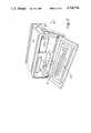
- FIG. 5 is a perspective view of a console unit useful for reading out information stored in memory in the probe shown in FIGS. 1 through 4;
- FIG. 6 is a simplified electronic block diagram illustrating the console unit shown in FIG. 5;
- FIGS. 7, 8, and 9 are logic flow charts illustrating typical operation of the monitoring device of this invention in the programming mode (with the probe connected with a console unit), measurement and storage mode (with the probe isolated and at a monitoring area), and in the readout mode (with the probe connected with the console unit);
- FIG. 10 is a perspective view illustrating a typical use of the probe of this invention, as shown in FIGS. 1 through 4, within a container for monitoring temperature conditions of food within container when passing through an oven;
- FIG. 11 is a perspective view of an alternative embodiment of the probe unit of this invention showing positioning of the sensor within a separate housing spaced from the main housing for the associated electronic circuitry of the probe unit.
- the monitoring device, or probe, 12 of this invention is adapted for use at a monitoring area to sense a parameter thereat, with the information being then stored in memory until the probe is removed from the monitoring area.
- the probe of this invention is particularly well suited for use in monitoring temperature to gain a temperature-time history (as is important, for example, for determining the extent of cooking that has occurred during food processing) or other temperature profiles (such as, for example, for determining the temperatures and times to which sensitive chemicals have been subjected during shipment or the like).
- the probe of this invention is well suited for use in monitoring parameters other than temperature, including vibration/shock, pressure, strain, Ph, acceleration, conductivity and/or radiation through the use of sensors, or transducers, providing output signals indicative thereof.
- temperature including vibration/shock, pressure, strain, Ph, acceleration, conductivity and/or radiation
- this invention is not meant to be limited to sensing and/or monitoring only this parameter.
- Monitoring device, or probe, 12 includes a housing 13 having first and second coaxially positioned cylindrical sections 14 and 15 connected with one another at annular protrusion 16.
- section 15 is connected with a coaxially positioned sensor containing cylinder, or tube, 17 at annular protrusion 18.
- Housing 13, when fully assembled, provides a sealed enclosure that is electrically conductive and is preferably formed of metal, such as stainless steel, so that, when assembled, the housing completely encases sensor 19 (in section 17) and associated electronic unit, or circuitry, 20 (in section 14) so that the probe is thereafter a self-sufficient device, which, as brought out more fully hereinafter, is electrically isolated when at the monitoring area for operation in the contemplated manner.
- section 15 of housing 13 also includes band 22, which band is also electrically conductive and is also preferably formed of metal, such as stainless steel.
- Band 22 is electrically insulated from the remainder of the housing by insulator 23, and band 22 enables ready readout of information stored in the probe after removal of the probe from the monitoring area as brought out more fully hereinafter.
- housing, or casing, 13 may vary, as needed for a particular application, it has been found that a relatively small miniaturized probe with a first cylindrical section 14 having a diameter of not more than about 1.375 inches and an axial length of not more than about 0.75 inches, a second cylindrical section 15 having a diameter of not more than about 0.98 inches and an axial length of not more than about 0.40 inches, and a third cylindrical section, or tube, 17 having a diameter of not more than about 0.38 inches and an axial length of up to not more than about 5 inches, can be utilized for sensing temperature within a range of between about -40° C. and +150° C. with a temperature accuracy of at least ⁇ 0.1° C.
- sensor 19 is positioned in tubular cylindrical section 17 (preferably at the end thereof most removed from the other cylindrical sections) and is connected with the associated electronic circuitry 20 of the probe, which circuitry is positioned in the largest cylindrical section 14, through lead 24.
- Sensor 19 and electrical circuitry 20 are shown in block form in FIG. 3 and are shown in greater detail in the schematic presentation of FIG. 4A-C.
- Sensor 19 is commonly an analog transducer that provides an analog output signal through lead 24 to analog-to-digital (A/D) converter 26 of electronic unit, or circuitry, 20 (if a digital transducer is utilized, then no A/D converter would be needed).
- A/D converter 26 converts received analog signals to digital output signals which are coupled to timer/counter unit 28 and to microprocessor unit 30.
- Timer/converter unit 28 provides timing functions for the probe, while microprocessor unit 30 controls operation of the probe.
- microprocessor unit 30 is preferably a CMOS micro (an RCA 1802 has been preferably used in a working embodiment of this invention).
- the microprocessor unit is therefore an 8-bit microprocessor (meaning the data path and internal organization are 8-bits wide).
- the address bus of the microprocessor is 16-bits wide, allowing access to 65536 memory locations.
- the address and data bus are not multiplexed but instead, the high order (8-bits) and low order (8-bits) are multiplexed with the higher order being latched by the address decoder unit 32.
- Microprocessor 30 has programmable read only memory (PROM) unit 34 (UVEPROM being utilized) and random access memory (RAM) unit 35 connected therewith with address decoder unit 32 being utilized for enabling the 8-bit to 16-bit circuit handling capabilities as needed.
- PROM programmable read only memory
- RAM random access memory
- Both the RAM and UVEPROM units utilized in this invention incorporate 2048 ⁇ 8 bytes. This is achieved by utilizing address decoder unit 32 (which is formed by RCA 1859). Four bits are latched--the two lowest and their inverses are passed to output pins while, as shown in FIG. 4C, the other two are decoded into four active low and mutually exclusive outputs (CE0, CE1, CE2, and CE3).
- memory access lines (A10) are generated and a low chip enable (CE) for each device is generated (this is accomplished from the decoder output on lines CE0 and CE2).
- CE chip enable
- two NAND GATES 36 and 37 are utilized in their DeMorgan equivalents to decode the chip enables (while this would appear to violate logic convention since the inputs of the RAM and UVEPROM are active low and the outputs of the equivalent gates are active high, this is not the case since the CE outputs are mutually exclusive meaning that one and only one of them may be low at any one time so that when the enable pin of the address decoder is pulled low, one of the CE outputs will always be low and by connecting this output to the NAND GATES the proper function is generated).
- mode control unit 39 is connected with timer/counter unit 28 and microprocessor 30 to control power application to the probe components with low power requirements being utilized throughout, and with power consumption being still further reduced when the probe is in an inactive, or sleep, mode during which no parameter sensing or storing of information in memory occurs.
- a clock 40 is also provided, and clock inputs are provided therefrom to timer/counter unit 28 and through divide-by-four ( ⁇ 4) unit 41 to timer/converter unit 28. As also indicated in FIG. 3, the probe is entirely powered by batteries 42 within the probe casing.
- the software programs that implement the probe operation are initially programmed into UVEPROM unit 34 prior to sealing the probe within housing 13.
- the additionally needed variable elements of probe software are loaded into RAM unit 35 by use of console unit 44 (shown in FIGS. 5 and 6) to establish the time and length of occurrence of sampling of the parameters.
- a bidirectional two wire master-slave protocol is implemented with error checking achieved by horizontal and vertical parity calculation (geometric error control).
- the console unit prompts the probe with serial encoded bit stream that contains, among other things, the delay time and sample rate selected by the user.
- the probe decodes this bit stream, checks it for errors and, if no error has occurred, stores the information in RAM unit 35 and re-transmits it to the console unit.
- a typical programming mode operation is shown in the logic flow chart of FIG. 7.
- mode control 39 causes electronic circuitry 20 to be activated from that of the standby, or sleep, mode.
- Sensor 19 then provides analog signals indicative of the sensed parameter to integrating A/D converter 26, which converter is an integrating converter, and which converter then provides a digital output signal, indicative of the received analog signal, to timer/counter unit 28, which also receives a clock input from clock unit 40.
- timer/counter 28 which includes countdown timers, starts a count which is terminated by the A/D converter depending upon the value of the sensed parameter. This count is then stored in RAM unit 35.
- RAM unit 35 After removal of the probe from the monitoring area, the information stored in RAM unit 35 is readily read out through I/O lead 45 connected with band 22 accessible at the exterior of the probe housing. A typical readout mode operation is shown in the logic flow chart of FIG. 9.
- FIG. 4A-C A schematic diagram of the probe specifically adapted for temperature sensing, is best shown in FIG. 4A-C.
- a thermistor (utilized as sensor 19) is connected at one side to the B+ side of battery unit 42.
- the B+ side of battery unit 42 provides the positive voltage for the probe unit, with the B+ side being connected with ground through capacitor 46.
- Casing 13 is also tied to the B+ power source so that signals are referenced to the casing at a voltage of approximately -3.5 volts.
- the I/O pin Under normal operating conditions at a monitoring area (and therefore not attached to the console unit), the I/O pin will be at the same potential as the case thereby creating no short circuit problems while the probe is at the a monitoring area.
- thermistor 19 is connected through lead 24 to the first input of comparator 47 of A/D converter unit 26 of electronic unit 20.
- Lead 24 is also connected with a first side of parallel connected capacitors 49, 50 and 51, which capacitors form an integrating capacitor.
- the second input of comparator 47 is connected with the center tap of resistor 53, which resistor is connected at one side to the B+power supply (i.e., the positive side of battery unit 42) and at the other side to the second side of capacitors 49 through 51.
- the output of comparator 47 is connected to the second, or reference, input of the comparator through series connected capacitor 55 and resistor 56, and to the B+power supply through resistor 58.
- Transistors 60 and 61 serve as switches for integrating A/D converter 26, with the bases of transistors 60 and 61 being connected with mode control unit 39 through resistors 63 and 64, respectively, and with the collector of transistor 61 being connected with capacitors 49 though 51 and with the first input of comparator 47.
- Mode control unit 39 includes a pair of flip-flops 66 and 67, with flip-flop 66 serving as a reset flip-flop and flip-flop 67 serving as a sleep mode flip-flop.
- reset flip-flop 66 receives a clock input from the NO output of microprocessor 30 to be set thereby to provide a Q output
- sleep flip-flop 67 receives a clock input from the TAO output of the conversion timer section of timer/counter unit 28.
- the Q output from reset flip-flop 66 is coupled to the base of transistor 61 of A/D converter unit 26, while the Q output of flip-flop 67 is couple to the base of transistor 60 and also provides an input to NAND gate 69 of clock unit 40.
- Analog-to-digital converter 26 allows sensing over a wide temperature range with low power consumption requirements, and yet provides 11-bit resolution (but could be expanded to 16-bit resolution).
- A/D converter 26 is a single slope integrating converter (as opposed to the more commonly used techniques of dual and triple slope integrating conversion).
- A/D circuit 26 Operation of A/D circuit 26 is relatively simple.
- the circuit is turned on by an input signal to transistor 60 (from flip-flop 67), which input signal also gates the system clock on (it was necessary to turn off the A/D circuit during the sleep mode to lower power consumption requirements).
- the integrating capacitor (made up of capacitors 49, 50 and 51) is discharged under program control by transistor 61, and the microprocessor initializes the conversion counter (the A counter of timer/counter unit 28) during this time.
- Transistor 61 is then turned off and the conversion counter is started simultaneously by the microprocessor unit.
- the microprocessor unit samples the EF2 output (output of comparator 47) periodically, and when the voltage on the capacitor equals the reference voltage (as set by resistor 53), the EF2 output goes low. This signals the microprocessor that the conversion is complete and the conversion counter is stopped.
- the microprocessor unit then reads out the value of the conversion from timer/counter unit 28 and causes the information to be coupled to RAM unit 35 for storage and later recall. The microprocessor then causes the probe to again return to the sleep mode.
- Clock unit 40 includes an oscillator 71 (4.138 MHz) connected at one side with the second input of NAND GATE 69 and through capacitor 73 with ground. The other side of oscillator 71 is connected with ground through capacitor 75.
- NAND gate 69 provides a 1 MHz output to divide-by-four ( ⁇ 4) unit 41 (consisting of flip-flops 77 and 78).
- the Q output of flip-flop 78 of divider unit 41 provides a 1 MHz output to timer/counter unit 28 to initiate start of a sleep cycle.
- Oscillator 71 is also connected at the opposite sides thereof with divider unit 80 which provides a 64 Hz output signal for effectively requiring even lower power consumption to timer/counter unit 28 when the probe is in the sleep mode.
- the clock system utilized allows the average power requirements to be lowered to approximately 540 microwatts. This is accomplished by gating the 4 MHz clock off to all devices that use the high speed clock except when powered up for measuring a parameter and storing the same.
- the MA 0-7 connections of microprocessor unit 30 are connected with the A 0-7 connections of ultraviolet erasable programmable read only memory (UVEPROM) unit 34 and random access memory (RAM) unit 35.
- the BUS 0-7 connections of microprocessor unit 30 are connected with connections 0 0-7 of UVEPROM unit 34 and connection I/O 1-8 (which are also connected with connections DB 0-7 of timer/counter unit 28)
- the MRD connection of microprocessor unit 30 is connected with the DE connection of UVEPROM unit 34 and the RD connection of timer/counter unit 28
- the NO connection of microprocessor unit 30 is connected to provide the clock input to reset flip-flop 66 and the AO input to timer/counter unit 28
- the N1 connection of microprocessor unit 30 is connected with the A1 connection of timer/counter unit 28
- the N2 connection of microprocessor unit 30 is connected with the S connection of reset flip-flop 66 and to the A2 connection of timer/counter unit 28,
- UVEPROM unit 34 The P and Vpp connections of UVEPROM unit 34 are connected with the B+power supply through resistors 96 and 97, respectively, the A8 and A9 connections of UVEPROM unit 34 are connected with the A8 and A9 connections, respectively, of RAM unit 35 and address (or latch) decoder unit 32, the A10 connection of UVEPROM unit 34 is connected with the CEO output of latch/decoder unit 32 and one input of NAND gate 36 (the other input of which gate is connected with the CEI output of latch/decoder unit 32 and the output of which gate is connected to the CS and DE inputs of RAM unit 35, the A10 connection of RAM unit 35 is connected with the CE2 output of latch/decoder unit 32 and one input of NAND gate 37 (the other input of which is connected with the CE3 output of latch/decoder unit 32 and the output of which is connected to the ,ovs/CE/ input of UVEPROM unit 34), and the CS connection of counter/timer unit 28 is connected with the B+ power supply through resistor
- the probe of this invention satisfies a need for a monitoring device that is battery operated with very low power consumption, including a relatively large storage memory, can be serially read out by means of a single wire (plus a case ground wire), is relatively simple in structure with a minimum of chips being utilized, is operational over a temperature range of about -40° C. to +150° C. with an accuracy of at least 0.1° C., is able to make 11+ bit resolution measurements, and is adaptable for sensing a plurality of different parameters.
- the sleep timer (the B counter of timer/counter unit 28) must be loaded with appropriate values, including the control word. Then a jam A counter control is issued causing the TAO line to toggle which clocks a low into sleep flip-flop 67 to gate the 4 MHz clock output (from gate 69) off.
- Power-up from the sleep mode occurs when either the sleep timer (B counter of timer/counter unit 28) times out resulting in a low applied on the INT output of timer/counter unit 28, or the I/O line 45 is driven to approximately -3.5 volts with respect to the case (which indicates that the probe is in communication with the console unit).
- the sleep timer is never gated off, but instead receives an input from clock unit 40, which input is a divide by 223 output of the 4 MHz resulting in a 64 Hz clock.
- the probe is thereafter placed in use and inserted into the monitoring area (such as an oven, for example, where temperature is being sensed by a temperature sensing probe).
- the low power consumption (sleep) mode is maintained until a timer B timeout occurs to cause the probe to go into the active mode during which parameter sensing and information storage is achieved. After sensing and information storage have been accomplished, the probe again returns to the sleep mode.
- Console unit 44 as shown in FIG. 5, a general purpose computer modified for probe usage, is provided to read out the information stored in the probe after removal of the probe from the monitoring area. As shown, console unit 44 includes a receiving portion 101 for receiving the probe so that contact 102 contacts band 22 on the probe. This allows readout of the information stored in the RAM unit of the probe.
- a keyboard 104 is typically provided for the console unit, which console may be conventional except for design necessary for positioning and maintaining the probe in position for communication of the probe with the console.
- FIG. 6 A simplified block diagram of the console unit is shown in FIG. 6. As shown, an internal buss 106 is utilized, with the probe interface being provided through probe serial port 108 (connected with contact 102). In addition, internal buss 106 of console 104 is also connected with RS232 port 110 (a general purpose computer port to allow communication with another computer), parallel port 112 (for optional connection with a calibration device), I/O port 114 leading to printer 116, I/O port 118 leading to clock 120, microprocessor 122, RAM memory 124, ROM memory 126 and I/O port 128 leading to a display 130, and a keyboard scanner 132 (connected with keyboard 104).
- RS232 port 110 a general purpose computer port to allow communication with another computer
- parallel port 112 for optional connection with a calibration device
- I/O port 114 leading to printer 116
- I/O port 118 leading to clock 120
- microprocessor 122 RAM memory 124
- ROM memory 126 and I/O port 128 leading to a display 130
- probe 12 is programmed for the particular use desired, and then inserted into the monitoring area. This can be accomplished, for example, by transporting the temperature probe through an oven (or, in the alternative, leaving the probe within the oven for a period of time). As indicated in FIG. 10, probe 12 may also be placed within a container 134, such as a food container, to monitor the actual conditions of food within the container during processing of the food.
- a container 134 such as a food container
- FIG. 11 An alternate embodiment 136 of the probe is shown in FIG. 11. As shown, sensor 138 is outside container 140 housing the electronic circuitry and is connected therewith through electric connector 142. This embodiment can be used to good advantage, for example, where the sensor must be positioned at a location not readily accessible to the remainder of the electronic circuitry.
- this invention provides an improved device and method for sensing a parameter at a monitored area and storing information indicative thereof, which stored information is then later readily available after removal of the probe from the monitored area.
Abstract
Description
Claims (23)
Priority Applications (1)
| Application Number | Priority Date | Filing Date | Title |
|---|---|---|---|
| US06/932,446 US4718776A (en) | 1985-08-12 | 1986-11-17 | Portable monitoring device and method |
Applications Claiming Priority (2)
| Application Number | Priority Date | Filing Date | Title |
|---|---|---|---|
| US76465885A | 1985-08-12 | 1985-08-12 | |
| US06/932,446 US4718776A (en) | 1985-08-12 | 1986-11-17 | Portable monitoring device and method |
Related Parent Applications (1)
| Application Number | Title | Priority Date | Filing Date |
|---|---|---|---|
| US76465885A Continuation | 1985-08-12 | 1985-08-12 |
Publications (1)
| Publication Number | Publication Date |
|---|---|
| US4718776A true US4718776A (en) | 1988-01-12 |
Family
ID=27117499
Family Applications (1)
| Application Number | Title | Priority Date | Filing Date |
|---|---|---|---|
| US06/932,446 Expired - Lifetime US4718776A (en) | 1985-08-12 | 1986-11-17 | Portable monitoring device and method |
Country Status (1)
| Country | Link |
|---|---|
| US (1) | US4718776A (en) |
Cited By (27)
| Publication number | Priority date | Publication date | Assignee | Title |
|---|---|---|---|---|
| US4930902A (en) * | 1988-03-05 | 1990-06-05 | Akio Yata | Nursing bottles |
| US5043860A (en) * | 1989-05-12 | 1991-08-27 | Technology Licensing Corporation | Cooking appliance interface |
| US5211476A (en) * | 1991-03-04 | 1993-05-18 | Allflex Europe S.A. | Temperature recording system |
| US5262758A (en) * | 1991-09-19 | 1993-11-16 | Nam Young K | System and method for monitoring temperature |
| US5340019A (en) * | 1993-06-30 | 1994-08-23 | Honeywell Inc. | Electronic aquastat in immersible capsule |
| US5380091A (en) * | 1989-04-08 | 1995-01-10 | Alba Tools Limited | Indicating device |
| US5449234A (en) * | 1993-11-29 | 1995-09-12 | Caterpillar Inc. | Air temperature sensor |
| GB2296971A (en) * | 1995-01-10 | 1996-07-17 | Atomic Energy Authority Uk | Electronic monitor |
| US5539672A (en) * | 1993-12-13 | 1996-07-23 | Hobart Corporation | Microprocessor-based temperature control circuit |
| US5814721A (en) * | 1994-05-10 | 1998-09-29 | Alba Tools Limited | Fluid boiling point analyzer |
| US5997171A (en) * | 1986-02-10 | 1999-12-07 | Texas Instruments Incorporated | Method and system for digital data storage, abstraction and compression to preserve the most useful characteristics of the data |
| US6310552B1 (en) | 1991-08-06 | 2001-10-30 | North-South Corporation | Integrated firefighter safety monitoring and alarm system |
| US6367974B1 (en) * | 1999-04-19 | 2002-04-09 | Peter Lin | Thermocouple apparatus and well for containers having a flanged access opening |
| US6512358B2 (en) * | 2000-07-17 | 2003-01-28 | Endress + Hauser Gmbh + Co. | Measuring device for measuring a process variable |
| US6511223B1 (en) * | 2000-11-10 | 2003-01-28 | Electronic Controls Design, Inc. | Conveyor oven profiler with simplified temperature sensor connection scheme |
| US20030025613A1 (en) * | 2001-08-03 | 2003-02-06 | Kaye Instruments, Inc | Miniaturized self-contained sensors for monitoring and storing data as to temperature and the like at remote areas and removable therefrom for digital reading, and novel method of operating the same |
| US20030227394A1 (en) * | 2002-05-24 | 2003-12-11 | The Procter & Gamble Co | Sensor device and methods for using same |
| FR2850364A1 (en) * | 2003-01-23 | 2004-07-30 | Hugues Sebastien Sylva Etienne | Insulated outer container for transporting unstable blood products comprises foam-lined case with inner recesses for pouches and temperature controller |
| US20040190592A1 (en) * | 2003-03-28 | 2004-09-30 | Intempco Controls, Ltd. | Remotely programmable integrated sensor transmitter |
| US7038172B1 (en) * | 2003-05-16 | 2006-05-02 | Marshall Air Systems, Inc. | Conveyorized food broiling apparatus |
| US20060239331A1 (en) * | 2005-04-26 | 2006-10-26 | Schwegman John J | Wireless temperature sensing system for lyophilization processes |
| US20090175315A1 (en) * | 2005-04-26 | 2009-07-09 | John Jeffrey Schwegman | Wireless temperature sensing system for lyophilization processes |
| US20100040112A1 (en) * | 2008-08-13 | 2010-02-18 | Abb Technology Ag | Temperature sensor for a process engineering industrial installation |
| US20100128753A1 (en) * | 2008-11-26 | 2010-05-27 | Rubbermaid Incorporated | Multiple-Stage Thermometer and Temperature Monitoring |
| US20120172737A1 (en) * | 2010-12-31 | 2012-07-05 | Pai-Yang Lin | Measurement Device, Measurement System and Data Processing Method for Physiological signal |
| CN103616082A (en) * | 2013-12-12 | 2014-03-05 | 四川中测辐射科技有限公司 | Intelligent miniature temperature recorder |
| US20150185082A1 (en) * | 2013-12-27 | 2015-07-02 | Microchip Technology Incorporated | Digital Temperature Sensor with Integrated Timer and Burst Mode |
Citations (12)
| Publication number | Priority date | Publication date | Assignee | Title |
|---|---|---|---|---|
| US4044238A (en) * | 1974-11-30 | 1977-08-23 | Felten & Guilleaume Carlswerk Ag | Method and arrangement for measuring and evaluating temperatures in temperature processed goods |
| US4048852A (en) * | 1975-06-12 | 1977-09-20 | Kabushiki Kaisha Takuma | Integrating calorimeter |
| US4109527A (en) * | 1976-10-26 | 1978-08-29 | The Dow Chemical Company | Device for measuring pH and temperature of a liquid, which includes a memory |
| US4198676A (en) * | 1978-12-20 | 1980-04-15 | Livezey Robert L Jr | General purpose electronic thermometer having selective data recovery, data conversion, and data derivation capabilities |
| US4241971A (en) * | 1979-09-04 | 1980-12-30 | General Motors Corporation | Pigtail assembly |
| WO1982001589A1 (en) * | 1980-10-16 | 1982-05-13 | Larsen Egon C | A heat meter and a system comprising such meters for separate,automatic registration of heat comsumption |
| DE3044262A1 (en) * | 1980-03-20 | 1982-06-03 | Horst Prof. Dr. 4790 Paderborn Ziegler | Thermal consumption measurement unit - provides display when required using periodic or requested storage for plug-in display |
| US4403296A (en) * | 1980-12-18 | 1983-09-06 | Electromedics, Inc. | Measuring and determination device for calculating an output determination based on a mathematical relationship between multiple different input responsive transducers |
| US4455095A (en) * | 1980-05-08 | 1984-06-19 | Werner Bleiker | System for measuring the heat energy emission of room heating elements |
| US4480312A (en) * | 1981-08-14 | 1984-10-30 | Wingate Steven L | Temperature sensor/controller system |
| US4518839A (en) * | 1982-03-03 | 1985-05-21 | Hitachi Heating Appliances Co., Ltd. | High frequency heating apparatus with wireless temperature probe |
| US4593370A (en) * | 1982-07-26 | 1986-06-03 | Hayati Balkanli | Environmental measuring and recording apparatus |
-
1986
- 1986-11-17 US US06/932,446 patent/US4718776A/en not_active Expired - Lifetime
Patent Citations (13)
| Publication number | Priority date | Publication date | Assignee | Title |
|---|---|---|---|---|
| US4044238A (en) * | 1974-11-30 | 1977-08-23 | Felten & Guilleaume Carlswerk Ag | Method and arrangement for measuring and evaluating temperatures in temperature processed goods |
| US4048852A (en) * | 1975-06-12 | 1977-09-20 | Kabushiki Kaisha Takuma | Integrating calorimeter |
| US4109527A (en) * | 1976-10-26 | 1978-08-29 | The Dow Chemical Company | Device for measuring pH and temperature of a liquid, which includes a memory |
| US4198676A (en) * | 1978-12-20 | 1980-04-15 | Livezey Robert L Jr | General purpose electronic thermometer having selective data recovery, data conversion, and data derivation capabilities |
| US4241971A (en) * | 1979-09-04 | 1980-12-30 | General Motors Corporation | Pigtail assembly |
| DE3044262A1 (en) * | 1980-03-20 | 1982-06-03 | Horst Prof. Dr. 4790 Paderborn Ziegler | Thermal consumption measurement unit - provides display when required using periodic or requested storage for plug-in display |
| US4455095A (en) * | 1980-05-08 | 1984-06-19 | Werner Bleiker | System for measuring the heat energy emission of room heating elements |
| WO1982001589A1 (en) * | 1980-10-16 | 1982-05-13 | Larsen Egon C | A heat meter and a system comprising such meters for separate,automatic registration of heat comsumption |
| US4473307A (en) * | 1980-10-16 | 1984-09-25 | Iss Clorius International A.S. | Heat meter system including means for separate, automatic registration of heat consumption |
| US4403296A (en) * | 1980-12-18 | 1983-09-06 | Electromedics, Inc. | Measuring and determination device for calculating an output determination based on a mathematical relationship between multiple different input responsive transducers |
| US4480312A (en) * | 1981-08-14 | 1984-10-30 | Wingate Steven L | Temperature sensor/controller system |
| US4518839A (en) * | 1982-03-03 | 1985-05-21 | Hitachi Heating Appliances Co., Ltd. | High frequency heating apparatus with wireless temperature probe |
| US4593370A (en) * | 1982-07-26 | 1986-06-03 | Hayati Balkanli | Environmental measuring and recording apparatus |
Cited By (39)
| Publication number | Priority date | Publication date | Assignee | Title |
|---|---|---|---|---|
| US5997171A (en) * | 1986-02-10 | 1999-12-07 | Texas Instruments Incorporated | Method and system for digital data storage, abstraction and compression to preserve the most useful characteristics of the data |
| US5000581A (en) * | 1988-03-05 | 1991-03-19 | Akio Yata | Nursing bottles |
| US4930902A (en) * | 1988-03-05 | 1990-06-05 | Akio Yata | Nursing bottles |
| US5380091A (en) * | 1989-04-08 | 1995-01-10 | Alba Tools Limited | Indicating device |
| US5043860A (en) * | 1989-05-12 | 1991-08-27 | Technology Licensing Corporation | Cooking appliance interface |
| US5211476A (en) * | 1991-03-04 | 1993-05-18 | Allflex Europe S.A. | Temperature recording system |
| US6310552B1 (en) | 1991-08-06 | 2001-10-30 | North-South Corporation | Integrated firefighter safety monitoring and alarm system |
| US5262758A (en) * | 1991-09-19 | 1993-11-16 | Nam Young K | System and method for monitoring temperature |
| US5340019A (en) * | 1993-06-30 | 1994-08-23 | Honeywell Inc. | Electronic aquastat in immersible capsule |
| US5449234A (en) * | 1993-11-29 | 1995-09-12 | Caterpillar Inc. | Air temperature sensor |
| US5539672A (en) * | 1993-12-13 | 1996-07-23 | Hobart Corporation | Microprocessor-based temperature control circuit |
| US5814721A (en) * | 1994-05-10 | 1998-09-29 | Alba Tools Limited | Fluid boiling point analyzer |
| GB2296971A (en) * | 1995-01-10 | 1996-07-17 | Atomic Energy Authority Uk | Electronic monitor |
| US6367974B1 (en) * | 1999-04-19 | 2002-04-09 | Peter Lin | Thermocouple apparatus and well for containers having a flanged access opening |
| US6512358B2 (en) * | 2000-07-17 | 2003-01-28 | Endress + Hauser Gmbh + Co. | Measuring device for measuring a process variable |
| US6511223B1 (en) * | 2000-11-10 | 2003-01-28 | Electronic Controls Design, Inc. | Conveyor oven profiler with simplified temperature sensor connection scheme |
| CN100420926C (en) * | 2001-08-03 | 2008-09-24 | 凯伊器械公司 | Improved miniaturized self-contained sensors for monitoring and storing data |
| US6836220B2 (en) * | 2001-08-03 | 2004-12-28 | Kaye Instruments, Inc. | Miniaturized self-contained sensors for monitoring and storing data as to temperature and the like at remote areas and removable therefrom for digital reading, and novel method of operating the same |
| US20030025613A1 (en) * | 2001-08-03 | 2003-02-06 | Kaye Instruments, Inc | Miniaturized self-contained sensors for monitoring and storing data as to temperature and the like at remote areas and removable therefrom for digital reading, and novel method of operating the same |
| KR100840634B1 (en) | 2001-08-03 | 2008-06-24 | 지이 카예 인스트러먼츠 인크. | Improved miniaturized self-contained sensors for monitoring and storing data |
| WO2003014680A1 (en) * | 2001-08-03 | 2003-02-20 | Kaye Instruments Inc. | Improved miniaturized self-contained sensors for monitoring and storing data |
| US6958693B2 (en) | 2002-05-24 | 2005-10-25 | Procter & Gamble Company | Sensor device and methods for using same |
| US20030227394A1 (en) * | 2002-05-24 | 2003-12-11 | The Procter & Gamble Co | Sensor device and methods for using same |
| FR2850364A1 (en) * | 2003-01-23 | 2004-07-30 | Hugues Sebastien Sylva Etienne | Insulated outer container for transporting unstable blood products comprises foam-lined case with inner recesses for pouches and temperature controller |
| US20040190592A1 (en) * | 2003-03-28 | 2004-09-30 | Intempco Controls, Ltd. | Remotely programmable integrated sensor transmitter |
| US7223014B2 (en) | 2003-03-28 | 2007-05-29 | Intempco Controls Ltd. | Remotely programmable integrated sensor transmitter |
| US7038172B1 (en) * | 2003-05-16 | 2006-05-02 | Marshall Air Systems, Inc. | Conveyorized food broiling apparatus |
| US20060239331A1 (en) * | 2005-04-26 | 2006-10-26 | Schwegman John J | Wireless temperature sensing system for lyophilization processes |
| US7520670B2 (en) * | 2005-04-26 | 2009-04-21 | John Jeffrey Schwegman | Wireless temperature sensing system for lyophilization processes |
| US20090175315A1 (en) * | 2005-04-26 | 2009-07-09 | John Jeffrey Schwegman | Wireless temperature sensing system for lyophilization processes |
| US20100040112A1 (en) * | 2008-08-13 | 2010-02-18 | Abb Technology Ag | Temperature sensor for a process engineering industrial installation |
| US8444318B2 (en) * | 2008-08-13 | 2013-05-21 | Abb Technology Ag | Temperature sensor for a process engineering industrial installation |
| US20100128753A1 (en) * | 2008-11-26 | 2010-05-27 | Rubbermaid Incorporated | Multiple-Stage Thermometer and Temperature Monitoring |
| US20120172737A1 (en) * | 2010-12-31 | 2012-07-05 | Pai-Yang Lin | Measurement Device, Measurement System and Data Processing Method for Physiological signal |
| CN103616082A (en) * | 2013-12-12 | 2014-03-05 | 四川中测辐射科技有限公司 | Intelligent miniature temperature recorder |
| CN103616082B (en) * | 2013-12-12 | 2015-09-23 | 四川中测辐射科技有限公司 | A kind of intelligent miniature temperature recorder |
| US20150185082A1 (en) * | 2013-12-27 | 2015-07-02 | Microchip Technology Incorporated | Digital Temperature Sensor with Integrated Timer and Burst Mode |
| US9664571B2 (en) * | 2013-12-27 | 2017-05-30 | Microchip Technology Incorporated | Digital temperature sensor with integrated timer and burst mode |
| US10352772B2 (en) | 2013-12-27 | 2019-07-16 | Microchip Technology Incorporated | Digital temperature sensor with integrated timer and burst mode |
Similar Documents
| Publication | Publication Date | Title |
|---|---|---|
| US4718776A (en) | Portable monitoring device and method | |
| US4217645A (en) | Battery monitoring system | |
| EP0417274B1 (en) | Electronic clinical thermometer | |
| US4592018A (en) | Removable RAM package for ambulatory medical monitor | |
| KR970002765B1 (en) | Reconfigurable remote control apparatus and method of using the same | |
| US4461584A (en) | Electronic clinical thermometer | |
| US5337234A (en) | Self-contained downhole gauge system | |
| US4709234A (en) | Power-conserving self-contained downhole gauge system | |
| KR920001964B1 (en) | Integrated processor including the trace-data pool | |
| KR880009319A (en) | Portable card for recording and reading information | |
| JP2004503015A5 (en) | ||
| US4665398A (en) | Method of sampling and recording information pertaining to a physical condition detected in a well bore | |
| JPH07506188A (en) | Data logger | |
| EP0343344A3 (en) | Semiconductor memory device with improved indicator of the state of the redundant structure | |
| WO2000025095A1 (en) | Environmental sensor | |
| US4763259A (en) | Memory processing systems for well tools | |
| US4557608A (en) | Thermal microstructure measurement system | |
| US5424547A (en) | UV curemeter and method | |
| JPS57117187A (en) | Discriminating method for memory | |
| US20110098939A1 (en) | Process analytic sensor with low power memory write function | |
| JPH0611474Y2 (en) | Battery voltage recorder | |
| JPH01263797A (en) | Physical quantity recording device for rotary object | |
| CA2065613A1 (en) | Self-contained downhole gauge system | |
| JPH0325232Y2 (en) | ||
| RU21092U1 (en) | ELECTRONIC TEMPERATURE RECORDER |
Legal Events
| Date | Code | Title | Description |
|---|---|---|---|
| AS | Assignment |
Owner name: BALL CORPORATION, P.O. BOX 589, BROOMFIELD, CO., 8 Free format text: ASSIGNMENT OF ASSIGNORS INTEREST.;ASSIGNORS:GILLAND, JERRY R.;SWEENEY, CHRISTOPHER L.;WERTZ, RONALD D.;REEL/FRAME:004644/0700 Effective date: 19861113 Owner name: BALL CORPORATION, A CORP OF CO., COLORADO Free format text: ASSIGNMENT OF ASSIGNORS INTEREST;ASSIGNORS:GILLAND, JERRY R.;SWEENEY, CHRISTOPHER L.;WERTZ, RONALD D.;REEL/FRAME:004644/0700 Effective date: 19861113 |
|
| STCF | Information on status: patent grant |
Free format text: PATENTED CASE |
|
| AS | Assignment |
Owner name: MESA MEDICAL INC., COLORADO Free format text: ASSIGNMENT OF ASSIGNORS INTEREST.;ASSIGNOR:BALL CORPORATION, A CORP. OF IN.;REEL/FRAME:005122/0705 Effective date: 19890601 |
|
| FEPP | Fee payment procedure |
Free format text: PAT HOLDER CLAIMS SMALL ENTITY STATUS - SMALL BUSINESS (ORIGINAL EVENT CODE: SM02); ENTITY STATUS OF PATENT OWNER: SMALL ENTITY |
|
| FPAY | Fee payment |
Year of fee payment: 4 |
|
| FPAY | Fee payment |
Year of fee payment: 8 |
|
| FPAY | Fee payment |
Year of fee payment: 12 |