US4465958A - Motor speed control circuit - Google Patents
Motor speed control circuit Download PDFInfo
- Publication number
- US4465958A US4465958A US06/371,408 US37140882A US4465958A US 4465958 A US4465958 A US 4465958A US 37140882 A US37140882 A US 37140882A US 4465958 A US4465958 A US 4465958A
- Authority
- US
- United States
- Prior art keywords
- terminal
- motor
- direct current
- voltage regulating
- control circuit
- Prior art date
- Legal status (The legal status is an assumption and is not a legal conclusion. Google has not performed a legal analysis and makes no representation as to the accuracy of the status listed.)
- Expired - Lifetime
Links
Images
Classifications
-
- H—ELECTRICITY
- H02—GENERATION; CONVERSION OR DISTRIBUTION OF ELECTRIC POWER
- H02P—CONTROL OR REGULATION OF ELECTRIC MOTORS, ELECTRIC GENERATORS OR DYNAMO-ELECTRIC CONVERTERS; CONTROLLING TRANSFORMERS, REACTORS OR CHOKE COILS
- H02P7/00—Arrangements for regulating or controlling the speed or torque of electric DC motors
- H02P7/06—Arrangements for regulating or controlling the speed or torque of electric DC motors for regulating or controlling an individual dc dynamo-electric motor by varying field or armature current
- H02P7/18—Arrangements for regulating or controlling the speed or torque of electric DC motors for regulating or controlling an individual dc dynamo-electric motor by varying field or armature current by master control with auxiliary power
- H02P7/24—Arrangements for regulating or controlling the speed or torque of electric DC motors for regulating or controlling an individual dc dynamo-electric motor by varying field or armature current by master control with auxiliary power using discharge tubes or semiconductor devices
- H02P7/28—Arrangements for regulating or controlling the speed or torque of electric DC motors for regulating or controlling an individual dc dynamo-electric motor by varying field or armature current by master control with auxiliary power using discharge tubes or semiconductor devices using semiconductor devices
- H02P7/285—Arrangements for regulating or controlling the speed or torque of electric DC motors for regulating or controlling an individual dc dynamo-electric motor by varying field or armature current by master control with auxiliary power using discharge tubes or semiconductor devices using semiconductor devices controlling armature supply only
- H02P7/288—Arrangements for regulating or controlling the speed or torque of electric DC motors for regulating or controlling an individual dc dynamo-electric motor by varying field or armature current by master control with auxiliary power using discharge tubes or semiconductor devices using semiconductor devices controlling armature supply only using variable impedance
Definitions
- the instant application is related to the field of speed control for electric motors.
- the instant application relates to a speed control for a direct current motor incorporated in a trolling motor assembly for use in fishing.
- Electrically-powered trolling motors are used to slowly propel a boat used in fishing through the water, to provide relative movement between the water and the bait being used, to provide a more lifelike appearance to the bait.
- a storage battery is used as the source of direct current power, and conventionally a tapped dropping resistor is connected between the source of direct current power and a direct current motor, coupled to a propeller.
- This tapped dropping resistor may be in a separate enclosure within the boat, or, in one commercially-available system, includes a tapped resistor formed by wire wound in a manner to conform to the inner surface of a housing containing the direct current motor. The housing is submerged in use, and the proximity of the wire forming the tapped resistor to the housing provides cooling for the resistor.
- Providing separate dropping resistors in a separate housing is both expensive and bulky, and the technique of winding wires about the inner surface of a submersible housing is difficult and costly to manufacture.
- the instant invention overcomes these and other deficiencies of the known prior art.
- the instant invention provides a motor speed control circuit for a trolling motor by interposing a semiconductor device between a direct current motor and a source of direct current power, and controlling the semiconductor device by means of a selector switch selecting one of a plurality of voltage regulating devices to be connected between the source of direct current power and a control terminal of the semiconductor device.
- the semiconductor device, and the voltage regulating devices may be easily and conveniently bonded to a submersible housing, providing a simple and convenient technique for manufacturing a trolling motor assembly.
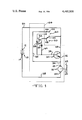
- FIG. 1 is a partially schematic drawing illustrating the motor speed control circuit of the invention.
- the preferred embodiment of the invention includes a conventional source of direct current power, shown as a battery 10 having a first or positive terminal 12 and a second or negative terminal 14, and a direct current motor 16 having a first terminal 18 and a second terminal 20.
- Direct current motor 16 is shown operatively coupled to a propeller 22 by motor shaft 24.
- a line 26 interconnects first or positive terminal 12 with a first controlled terminal 28 of a semiconductor device 30, here shown as an NPN transistor.
- Semiconductor device 30 also includes a second controlled terminal 32 and a control terminal 34. As illustrated, first controlled terminal 28 is the collector of transistor 30, second controlled terminal 32 is the emitter, and control terminal 34 is the base. Terminal 32 of transistor 30 is connected to first terminal 18 of motor 16 by a line 36, and terminal 20 of motor 16 is connected to terminal 14 of battery 10 by return line 38.
- a selector switch 40 is shown as including a movable or wiper element 42, electrically connected to terminal 28 of transistor 30 and to positive terminal 12 of battery 10, and a plurality of fixed contacts such as first contact 44, second contact 46, third contact 48 and fourth contact 50.
- Selector switch 40 is shown with wiper element 42 contacting third contact 48.
- First contact 44 is connected, through a line 52 to second control terminal 32 of transistor 30, and to first terminal 18 of motor 16, so that when movable wiper element 44 is in contact with first contact 44, transistor 30 will be bypassed or shunted, providing full-speed operation of motor 16.
- Second contact 44 is connected to a first terminal 54 of a voltage regulating device 56, which has its second terminal 58 connected to control terminal 34.
- voltage regulating device 56 is a zener diode having a cathode 54 and an anode terminal 58.
- Third contact 48 is connected to a first terminal 60 of a voltage regulating device 62, which has a second terminal 64 connected to control terminal 34.
- voltage regulating device 62 is a zener diode with a cathode terminal 60 and an anode terminal 64.
- a fourth contact 50 of selector switch 40 is shown unconnected.
- connection between wiper 42 and contact 44 provides full-speed operation
- contact between wiper 42 and contact 46 provides interemediate-speed operation
- contact between wiper 42 and contact 48 provides low-speed operation
- connection between wiper 42 and contact 50 de-energizes motor 16.
- voltage regulating devices 56 and 62, transistor 30 and motor 16 are disposed within a submersible housing 66, indicated symbolically in broken line.
- control terminal 34 and controlled terminal 32 is substantially constant, and is a parameter of transistor 30.
- the voltage across zener diode 56, or zener diode 62, is a constant, and is a parameter of the voltage regulating device chosen.
- the voltage appearing between terminals 18 and 20 will be the voltage provided by battery 10, less that, if any, produced by zener diodes 56 or 60, and the voltage between terminals 34 and 36.
- the instant invention provides a simple, convenient, easy to manufacture and inexpensive circuit for controlling the speed of a trolling motor, with only a few simple components.
- the number of speeds selectable by a selector switch such as 40 may be varied by changing the number of fixed contacts, and providing additional voltage regulating devices such as zener diodes.
- a selector switch such as 40
- additional voltage regulating devices such as zener diodes.
Abstract
Description
Claims (2)
Priority Applications (1)
| Application Number | Priority Date | Filing Date | Title |
|---|---|---|---|
| US06/371,408 US4465958A (en) | 1982-04-26 | 1982-04-26 | Motor speed control circuit |
Applications Claiming Priority (1)
| Application Number | Priority Date | Filing Date | Title |
|---|---|---|---|
| US06/371,408 US4465958A (en) | 1982-04-26 | 1982-04-26 | Motor speed control circuit |
Publications (1)
| Publication Number | Publication Date |
|---|---|
| US4465958A true US4465958A (en) | 1984-08-14 |
Family
ID=23463870
Family Applications (1)
| Application Number | Title | Priority Date | Filing Date |
|---|---|---|---|
| US06/371,408 Expired - Lifetime US4465958A (en) | 1982-04-26 | 1982-04-26 | Motor speed control circuit |
Country Status (1)
| Country | Link |
|---|---|
| US (1) | US4465958A (en) |
Cited By (7)
| Publication number | Priority date | Publication date | Assignee | Title |
|---|---|---|---|---|
| US4719395A (en) * | 1986-12-22 | 1988-01-12 | Omron Tateisi Electronics Co. | Variable speed control switch for an electric tool including a DC motor |
| DE3726662A1 (en) * | 1987-08-11 | 1989-02-23 | Standard Elektrik Lorenz Ag | CIRCUIT ARRANGEMENT FOR SPEED ADJUSTMENT OF AN ELECTRONICALLY COMMUTED DC MOTOR |
| US5097184A (en) * | 1990-03-23 | 1992-03-17 | Hilti Aktiengesellschaft | Battery operated device |
| US5577155A (en) * | 1993-12-03 | 1996-11-19 | Buchbinder; Carl | Rectifier based motor speed/brake control |
| US5990582A (en) * | 1997-05-13 | 1999-11-23 | Micron Electronics, Inc. | Computer fan speed control device |
| US6247898B1 (en) | 1997-05-13 | 2001-06-19 | Micron Electronics, Inc. | Computer fan speed control system |
| US6526333B1 (en) | 1997-05-13 | 2003-02-25 | Micron Technology, Inc. | Computer fan speed control system method |
Citations (4)
| Publication number | Priority date | Publication date | Assignee | Title |
|---|---|---|---|---|
| US3348113A (en) * | 1964-05-07 | 1967-10-17 | Presna Mechanika Narodny Podni | Speed control circuit for a multispeed electric commutator motor |
| US3941198A (en) * | 1974-08-29 | 1976-03-02 | Kappas Chris S | Detachable power unit for a golf bag cart |
| US4008426A (en) * | 1974-11-28 | 1977-02-15 | Jeco Co., Ltd. | Electronic speed control systems for miniature direct current motors |
| US4296363A (en) * | 1974-09-09 | 1981-10-20 | Outboard Marine Corporation | Speed selection for a direct current permanent magnet motor |
-
1982
- 1982-04-26 US US06/371,408 patent/US4465958A/en not_active Expired - Lifetime
Patent Citations (4)
| Publication number | Priority date | Publication date | Assignee | Title |
|---|---|---|---|---|
| US3348113A (en) * | 1964-05-07 | 1967-10-17 | Presna Mechanika Narodny Podni | Speed control circuit for a multispeed electric commutator motor |
| US3941198A (en) * | 1974-08-29 | 1976-03-02 | Kappas Chris S | Detachable power unit for a golf bag cart |
| US4296363A (en) * | 1974-09-09 | 1981-10-20 | Outboard Marine Corporation | Speed selection for a direct current permanent magnet motor |
| US4008426A (en) * | 1974-11-28 | 1977-02-15 | Jeco Co., Ltd. | Electronic speed control systems for miniature direct current motors |
Cited By (7)
| Publication number | Priority date | Publication date | Assignee | Title |
|---|---|---|---|---|
| US4719395A (en) * | 1986-12-22 | 1988-01-12 | Omron Tateisi Electronics Co. | Variable speed control switch for an electric tool including a DC motor |
| DE3726662A1 (en) * | 1987-08-11 | 1989-02-23 | Standard Elektrik Lorenz Ag | CIRCUIT ARRANGEMENT FOR SPEED ADJUSTMENT OF AN ELECTRONICALLY COMMUTED DC MOTOR |
| US5097184A (en) * | 1990-03-23 | 1992-03-17 | Hilti Aktiengesellschaft | Battery operated device |
| US5577155A (en) * | 1993-12-03 | 1996-11-19 | Buchbinder; Carl | Rectifier based motor speed/brake control |
| US5990582A (en) * | 1997-05-13 | 1999-11-23 | Micron Electronics, Inc. | Computer fan speed control device |
| US6247898B1 (en) | 1997-05-13 | 2001-06-19 | Micron Electronics, Inc. | Computer fan speed control system |
| US6526333B1 (en) | 1997-05-13 | 2003-02-25 | Micron Technology, Inc. | Computer fan speed control system method |
Similar Documents
| Publication | Publication Date | Title |
|---|---|---|
| US3598947A (en) | Pedal operated control for electric fishing motors | |
| US4465958A (en) | Motor speed control circuit | |
| US4296363A (en) | Speed selection for a direct current permanent magnet motor | |
| IT8124346A0 (en) | CIRCUIT ARRANGEMENT TO ELECTRICALLY POWER AN ELECTRIC MOTOR WITH ADJUSTABLE RPM. | |
| US3906887A (en) | Electric outboard motor | |
| US4841203A (en) | Electric trolling motor steering system | |
| SE8404621L (en) | DEVICE FOR FEED ENGINE FEED, Separately for MOTOR VEHICLES | |
| US4075970A (en) | Speed selection for a direct current permanent magnet motor | |
| US3141429A (en) | Sewing machine with built-in electric speed-responsive regulating systems | |
| US3954081A (en) | Outboard motor with speed regulator for DC permanent magnet motor | |
| JPS54131207A (en) | Device for controlling electric car | |
| USRE29695E (en) | Outboard motor with speed regulator for DC permanent magnet motor | |
| SU1677767A1 (en) | Device for protection of dc electric drive | |
| US3188543A (en) | Battery operated electric motor control for vehicle | |
| US3109164A (en) | Indicating lamp and lens assembly for portable electric tools | |
| JPS57167868A (en) | Power steering device for motor driven pump | |
| KR830008858A (en) | Electric vehicle control device | |
| SU746847A1 (en) | Reversible dc electric drive | |
| SU151938A1 (en) | Automatic Transmission Control Device | |
| SU1149226A1 (en) | Two-position control of electroconductive medium level | |
| SU1051677A1 (en) | Electric drive | |
| SU535698A1 (en) | DC power supply | |
| SU1017531A1 (en) | Apparatus for controlling electric motors of fans of multisection rolling stock | |
| SU951616A1 (en) | Electric drive | |
| JPH022035Y2 (en) |
Legal Events
| Date | Code | Title | Description |
|---|---|---|---|
| AS | Assignment |
Owner name: ELTRA CORPORATION, A DE CORP. Free format text: ASSIGNMENT OF ASSIGNORS INTEREST.;ASSIGNOR:ROBERTS, WILLIAM J.;REEL/FRAME:004005/0185 Effective date: 19820419 Owner name: ELTRA CORPORATION, OHIO Free format text: ASSIGNMENT OF ASSIGNORS INTEREST;ASSIGNOR:ROBERTS, WILLIAM J.;REEL/FRAME:004005/0185 Effective date: 19820419 |
|
| AS | Assignment |
Owner name: ALLIED CORPORATION; COLUMBIA RD. AND PARK AVE., MO Free format text: ASSIGNMENT OF ASSIGNORS INTEREST.;ASSIGNOR:ELTRA CORPORATION;REEL/FRAME:004026/0293 Effective date: 19820531 Owner name: ALLIED CORPORATION, NEW JERSEY Free format text: ASSIGNMENT OF ASSIGNORS INTEREST;ASSIGNOR:ELTRA CORPORATION;REEL/FRAME:004026/0293 Effective date: 19820531 |
|
| STCF | Information on status: patent grant |
Free format text: PATENTED CASE |
|
| FEPP | Fee payment procedure |
Free format text: PAYOR NUMBER ASSIGNED (ORIGINAL EVENT CODE: ASPN); ENTITY STATUS OF PATENT OWNER: LARGE ENTITY |
|
| AS | Assignment |
Owner name: CITICORP INDUSTRIAL CREDIT, INC., 200 SOUTH WACKER Free format text: SECURITY INTEREST;ASSIGNOR:PRESTOLITE ELECTRIC INCORPORATED;REEL/FRAME:004568/0105 Effective date: 19860422 Owner name: CITICORP INDUSTRIAL CREDIT, INC., ILLINOIS Free format text: SECURITY INTEREST;ASSIGNOR:PRESTOLITE ELECTRIC INCORPORATED;REEL/FRAME:004568/0105 Effective date: 19860422 |
|
| FPAY | Fee payment |
Year of fee payment: 4 |
|
| AS | Assignment |
Owner name: PRESTOLITE ELECTRIC INCORPORATED, A CORP. OF DE Free format text: ASSIGNMENT OF ASSIGNORS INTEREST.;ASSIGNOR:ALLIED CORPORATION, A CORP. OF NY;REEL/FRAME:005869/0230 Effective date: 19860422 Owner name: PRESTOLITE ELECTRIC INCORPORATED, OHIO Free format text: ASSIGNMENT OF ASSIGNORS INTEREST;ASSIGNOR:ALLIED CORPORATION;REEL/FRAME:005869/0230 Effective date: 19860422 |
|
| FEPP | Fee payment procedure |
Free format text: PAYER NUMBER DE-ASSIGNED (ORIGINAL EVENT CODE: RMPN); ENTITY STATUS OF PATENT OWNER: LARGE ENTITY Free format text: PAYOR NUMBER ASSIGNED (ORIGINAL EVENT CODE: ASPN); ENTITY STATUS OF PATENT OWNER: LARGE ENTITY |
|
| AS | Assignment |
Owner name: CONGRESS FINANCIAL Free format text: SECURITY INTEREST;ASSIGNOR:PEI 1991 ACQUISITION, INC. A/K/A PRESTOLITE ELECTRIC COMPANYINCORPORATED;REEL/FRAME:005962/0243 Effective date: 19911029 Owner name: PRESTOLITE ELECTRIC INCORPORATED Free format text: RELEASE BY SECURED PARTY OF SECURITY AGREEMENTS RECORDED ON REEL 4568 FRAME 0105 AND REEL 4626 FRAME 0084-0095;ASSIGNOR:CITICORP NORTH AMERICA, INC., FORMERLY CITICORP INDUSTRIAL CREDIT, INC.;REEL/FRAME:005967/0610 Effective date: 19911025 Owner name: PEI 1991 ACQUISITION, INC. Free format text: ASSIGNMENT OF ASSIGNORS INTEREST.;ASSIGNOR:PRESTOLITE ELECTRIC INCORPORATED;REEL/FRAME:005967/0628 Effective date: 19911029 Owner name: CONGRESS FINANCIAL, ILLINOIS Free format text: SECURITY INTEREST;ASSIGNOR:PEI 1991 ACQUISITION, INC. A/K/A PRESTOLITE ELECTRIC COMPANYINCORPORATED;REEL/FRAME:005962/0243 Effective date: 19911029 Owner name: PRESTOLITE ELECTRIC INCORPORATED, OHIO Free format text: RELEASE BY SECURED PARTY OF SECURITY AGREEMENTS RECORDED ON REEL 4568 FRAME 0105 AND REEL 4626 FRAME 0084-0095;ASSIGNOR:CITICORP NORTH AMERICA, INC., FORMERLY CITICORP INDUSTRIAL CREDIT, INC.;REEL/FRAME:005967/0610 Effective date: 19911025 Owner name: PEI 1991 ACQUISITION, INC., OHIO Free format text: ASSIGNMENT OF ASSIGNORS INTEREST;ASSIGNOR:PRESTOLITE ELECTRIC INCORPORATED;REEL/FRAME:005967/0628 Effective date: 19911029 |
|
| FPAY | Fee payment |
Year of fee payment: 8 |
|
| AS | Assignment |
Owner name: PRESTOLITE ELECTRIC INCORPORATED, MICHIGAN Free format text: RELEASE BY SECURED PARTY;ASSIGNOR:CONGRESS FINANCIAL CORPORATION;REEL/FRAME:007185/0936 Effective date: 19941026 |
|
| FPAY | Fee payment |
Year of fee payment: 12 |
|
| AS | Assignment |
Owner name: PRESTOLITE ELECTRIC INCORPORATED, MICHIGAN Free format text: CHANGE OF NAME;ASSIGNOR:PEI 1991 ACQUISITION, INC.;REEL/FRAME:011164/0234 Effective date: 19911030 |