US4346407A - Apparatus for synchronization of a source of computer controlled video to another video source - Google Patents
Apparatus for synchronization of a source of computer controlled video to another video source Download PDFInfo
- Publication number
- US4346407A US4346407A US06/159,548 US15954880A US4346407A US 4346407 A US4346407 A US 4346407A US 15954880 A US15954880 A US 15954880A US 4346407 A US4346407 A US 4346407A
- Authority
- US
- United States
- Prior art keywords
- video
- source
- synchronization signals
- computer controlled
- phase
- Prior art date
- Legal status (The legal status is an assumption and is not a legal conclusion. Google has not performed a legal analysis and makes no representation as to the accuracy of the status listed.)
- Expired - Lifetime
Links
Images

Classifications
-
- H—ELECTRICITY
- H04—ELECTRIC COMMUNICATION TECHNIQUE
- H04N—PICTORIAL COMMUNICATION, e.g. TELEVISION
- H04N5/00—Details of television systems
- H04N5/04—Synchronising
- H04N5/06—Generation of synchronising signals
- H04N5/067—Arrangements or circuits at the transmitter end
-
- G—PHYSICS
- G09—EDUCATION; CRYPTOGRAPHY; DISPLAY; ADVERTISING; SEALS
- G09G—ARRANGEMENTS OR CIRCUITS FOR CONTROL OF INDICATING DEVICES USING STATIC MEANS TO PRESENT VARIABLE INFORMATION
- G09G5/00—Control arrangements or circuits for visual indicators common to cathode-ray tube indicators and other visual indicators
- G09G5/12—Synchronisation between the display unit and other units, e.g. other display units, video-disc players
Definitions
- the television field has been enhanced by two relatively new consumer products: the video tape recorder or video disc player and the personal computer.
- the video tape recorder or video disc player plays back video tapes or discs for displaying images on the screen of a television receiver or monitor.
- the personal computer employs the television receiver or monitor as a convenient display for displaying images such as graphics or alphanumerics on the screen thereof. Because of the advent of these two relatively new products, applications have arisen wherein it is desirable to display simultaneously on the television receiver or monitor screen the outputs from a video tape or disc player and a personal computer.
- Video tape recorders for example, have neither absolute frequency stability nor freedom from flutter, tape slippage and other deviations from an ideal playback medium.
- the central timing source of the personal computer that is, its system clock, cannot be frequency and phase locked directly to the chroma burst signal (3.58 MHz typically in NTSC systems) in an effort to synchronize the luminance signal of the personal computer with that of the playback unit.
- Table I illustrates the extent to which two different video tape recorders degrade the standard U.S. NTSC television signal, also shown in the table.
- the present invention has wide application whenever a computer terminal, such as the personal computers currently available, for example, the APPLE II, ATARI 400 and 800, Commodore PET, Radio Shack TRS 80, and others, is required to simultaneously display its own video output plus that coming from an external video source as, for example, a video tape recorder or disc player.
- a computer terminal such as the personal computers currently available, for example, the APPLE II, ATARI 400 and 800, Commodore PET, Radio Shack TRS 80, and others, is required to simultaneously display its own video output plus that coming from an external video source as, for example, a video tape recorder or disc player.
- Current models of such computers cannot be readily used in this fashion and at best it is possible to switch a television receiver or monitor between the video tape or disc source and the computer. Simultaneous display is not possible.
- the synchronization signals generated by the personal computer are submultiples of its system clock.
- Frequency coherence between the computer and a video tape recorder is achieved by generating the system clock for the computer from the synchronization signals outputted by the video tape recorder. This is achieved by multiplying the frequency of the horizontal synchronization signals by some predetermined amount.
- Phase coherence between the synchronization signals of the video tape recorder and personal computer is achieved by detecting any phase incoherence and in response thereto, causing the clock pulses for the computer to cease for a predetermined period to allow the computer to "slip" sync and, thus, obtain phase coherence.
- FIG. 1 is a block diagram of a system for synchronizing two video sources
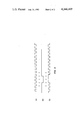
- FIG. 2 illustrates waveforms obtained from the system of FIG. 1 which are useful in explaining the operation thereof.
- FIG. 1 of the drawings The function of the present invention illustrated in FIG. 1 of the drawings is to establish and maintain synchronization between signals of two video sources providing images to be displayed on the screen of a television receiver or monitor.
- the two video sources for providing video images are a remote video generator, such as a video tape recorder 10 and a local video generator 12.
- Remote video generator 10 provides images 14 on the screen of a television receiver 16 while the local video generator 12 provides video images 18 for display on the same television receiver screen.
- video image 14 is a graphic illustration while video image 18 is alphanumerics; however, either of the sources 10 and 12 can provide both or either graphics or alphanumerics.
- Typical of the local video generator is a modified personal computer such as the APPLE II.
- the local video generator must be capable of generating a luminance signal that is in the standard NTSC format.
- the signal must include a frame that contains two fields each having 2621/2 lines.
- the frame includes 525 lines, interlaced two to one.
- Most personal computers must be slightly modified so that their video signals conform to the interlaced nature of the NTSC format. However, this forms no part of the present invention. With the ever increasing use of personal computers, it has become desirable to display video images from these personal computers in conjunction with other sources, such as video tape or disc playback units. Synchronization between remote video generator 10 and local video generator 12 must be provided in spite of the degradation of luminance, chroma, and synchronization signals outputted from typical video playback equipment.
- the system of FIG. 1 permits synchronizing the local video generator 12 to the remote video generator 10 to allow simultaneous display of video images from both sources on the television receiver 12.
- the output of the remote video generator 10 which includes luminance, chroma and vertical and horizontal synchronization signals, is applied to an AGC circuit 20 which maintains the output signals (levels) relatively constant. These signals are presented to a summer 22 via a line 24 for summing with other signals applied thereto.
- the output of summer 22 is coupled to the television receiver 16 via a line 26 in conventional fashion to provide pictorial representations 14 and 18 on the screen of the television receiver.
- the other inputs to summer 22 are the "local" color and "local” luminance signals which are applied to summer 22 via lines 28 and 30, respectively.
- the designation "local” indicates that these signals are locally generated by the local video generator 12 and not generated from the remote video generator 10.
- the local video generator 12 provides alphanumeric and/or graphic interlaced video luminance signals to line 30 and to summer 22 where they are combined with the color coded composite video signal emanating from the remote video generator on line 24.
- the local video generator 12 produces standard R-Y and B-Y color-phase signals on lines 32 and 34.
- the signals on line 32 and 34 are applied to a pair of modulators 36 and 38.
- Coupled to the AGC circuit 20 is a burst gate 42 linked to a burst amplifier 44, phase detector 46, narrow band filter 48, and a voltage controlled crystal oscillator 50.
- This system regenerates the chroma subcarrier on line 51.
- This system is the same as that used in color television receivers.
- the regenerated chroma subcarrier from line 51 is fed to the modulators 36 and 38 and summed in summer 40 in order to produce a local chroma signal 28.
- the method of producing a chroma signal is the same as that used in color television cameras.
- Local chroma signal 28 is fed to summer 22. For monochrome applications, this signal would be suppressed.
- a sync stripper 54 providing remote horizontal synchronization signals on line 56 and remote vertical synchronization signals on line 58.
- the remote horizontal synchronization signals are applied as a second input to burst gate 42 to gate incoming signals through the burst gate 42, to apply it to the burst amplifier 44 and use it to phase-lock the voltage controlled crystal oscillator 50 via phase detector 46 and narrow band filter 48.
- the output from the voltage controlled crystal oscillator 50 is fed back to the phase detector 46 for comparison with the chroma burst amplifier 44 output in conventional fashion.
- the object of this system is to permit summing the local video generator's video signals with those derived from a remote video generator such as a video tape recorder which is a relatively unstable video source. Synchronization must be obtained both for the horizontal and vertical synchronization signals and associated video signals generated by the two sources.
- the novel portion of the system includes a phase-locked loop multiplier chain 60 coupled to line 56 for receiving remote horizontal synchronization signals from sync stripper 54.
- the output of the phase-locked loop multiplier chain 60 is applied as one input to a NAND gate 62.
- the circuit also includes a pair of phase detectors 64 and 66.
- Horizontal phase detector 64 has as one input thereto the remote horizontal synchronization pulses from line 56 and as a second input thereto local horizontal synchronization signals via line 68 from the local video generator.
- the vertical phase detector 66 is similarly coupled like the phase detector 64 in that it receives as one input remote vertical synchronization signals from line 68 and at the other input local vertical synchronization signals from line 70 from the local video generator.
- the outputs 72 and 74 from the phase detectors 64 and 66 are applied to a gated digital one-shot 75 and in particular to an OR gate 76 thereof.
- the output from OR gate 76 is applied as one input to a NAND gate 78.
- the other input to NAND gate 78 is received from a digital one-shot 80 having as the input thereto horizontal synchronization signals from the local video generator 12.
- the digital one-shot 80 is configured to have an output pulse of a width equal to two cycles of the nominal clock frequency for local video generator 12.
- a high frequency clock signal is delivered to AND gate 62 via line 71.
- the gated digital one-shot 75 is used to periodically interrupt the clock signal whenever phase detectors 64 and 66 deem it necessary.
- the action of gated digital one-shot 75 will be described in greater detail hereinafter.
- the effect of the circuit is to generate on line 82 an uninterrupted clock with a frequency of 14.32 MHz or an interrupted clock with an effective frequency of 14.29 MHz.
- the circuitry just described comprises in substance two phase-locked loops.
- the first phase-locked loop includes the phase-locked loop multiplier chain 60 and the second phase-locked loop includes the phase detectors 64, 66, the gated digital one-shot 75, the NAND gate 62 and the local video generator 12.
- the function of the first phase-locked loop is to insure frequency coherence between the signals from the video tape recorder 10 and those of the local video generator 12, and the function of the second phase-locked loop is to insure phase coherence between the signals from the two sources.
- a synchronous digital system's outputs occur at rates which are submultiples of its clock frequency.
- the rate of the horizontal synchronization signal of the local video generator 12 on line 68 and the rate of the vertical synchronization signal on line 70 are submultiples of the local video generator's clock frequency.
- the system clock is applied to the local video generator via line 82, from the NAND gate 62. This signal is derived by multiplying the frequency of the horizontal synchronization signal from the video tape recorder 10, received on line 56 from sync stripper 54, in a phase-locked loop multiplier chain by some constant factor. In this embodiment, the multiplication factor is 910 which will provide a nominal clock frequency for the local video generator of 14.32 MHz.
- This signal now has the proper frequency which will permit local video generator 12 to output horizontal and vertical synchronization pulses on lines 68 and 70 that are indeed identical in frequency to those of remote video generator 10. If the horizontal and/or vertical synchronization signals from the video tape recorder vary, then the clock signal applied on line 82 will vary accordingly, since the clock signal is derived by multiplying such varying horizontal and vertical synchronization signals in the phase-locked loop multiplier chain 60.
- While the frequency of the horizontal and vertical synchronization signals from the local video generator 12 are made equal to those from the remote video generator 10 by varying the clock of the local video generator 12 in accordance with any variance of the horizontal and vertical synchronization signals from the remote video generator, these signals bear no absolute phase relationship to those of the synchronization signals from the remote video generator. It is the function of the phase detectors 64 and 66 to decode the phase relationship of two sets of horizontal and vertical synchronization signals (those from the remote video generator and those from the local video generator).
- phase detectors 64 and/or 66 detect a phase difference between the synchronization pulses from the remote video generator 10 and the synchronization pulses from the local video generator 12, they provide outputs via lines 72 and 74 to the OR gate 76 which applies an output to NAND gate 78.
- the NAND gate 78 is enabled by the output from the digital one-shot 80. Thus, when there are inputs to the NAND gate from OR gate 76 and the digital one-shot 80, the output of NAND gate 78 disables the NAND gate 62 preventing the application of clock signal to the local video generator 12.
- Waveform A of FIG. 2 illustrates the clock pulses applied to NAND gate 62 on line 71.
- the NAND gate 62 is disabled for the period of the digital one-shot 80. This period is the duration of two 14.32 MHz clock pulses.
- waveforms B and C of FIG. 2. The output of the NAND gate 78 shown in waveform B disables the NAND gate 62 causing the cessation of clock pulses on line 82 from being applied to the local video generator 12.
- the digital one-shot has a width of two of the 14.32 MHz clock pulses as shown by waveform C of FIG. 2, the clock pulses applied on line 82 to the local video generator 12 cease for two of such clock pulses. The disruption of the clock pulses to the local video generator 12 causes the local video generator 12 to "slip" sync.
- phase-locked loop multiplier chain 60 forms a minor phase-locked loop.
- phase-locked loop defined by the phase detectors 64, 66, 14.32 MHz clock on line 71, gated digital one-shot 75, NAND gate 62, and local video generator 12 forms a major phase-locked loop.
- the major phase-locked loop requires up to 910 fields to achieve lock. This interval is a function of the amount of slip that is allowed to occur, on a line to line basis, between the local video generator 12 and the remote video generator 10.
- phase and frequency compensations are performed by the minor loop. If the frequency of the line voltage increases, the speed of the remote video generator will increase, the frequency of the horizontal synchronization signals on line 56 will increase, the frequency of signals emanating from the minor loop 60 will increase, and the frequencies of the signals emanating from the local video generator 12 will increase. No phase errors will be detected by phase detectors 64 and 66.
- the minor phase-locked loop maintains control of the local video generator independent of the major phase-locked loop.
- the key points of operation of the luminance synchronization circuitry are as follows:
- a minor phase-locked loop frequency locks a local video generator to a remote video generator.
- a major phase-locked loop phase corrects a local video generator so that it is in phase with a remote video generator.
- the minor phase-locked loop operates totally independent of the major phase-locked loop.
- the minor phase-locked loop maintains lock even when the major phase-locked loop is not in a condition of lock.
- While the system has been designed for use in conjunction with an APPLE II personal computer, it is clearly generic and applies to other computers having a video display output capability such as the aforementioned Atari, Radio Shack and Commodore personal computer systems. It can further readily be seen that the system of the present invention can be used additionally in conjunction with sources of video other than video tape or disc playback units. For example, television cable transmission or on-the-air transmission, after reception by a suitable TV receiver, could deliver the required video and synchronization signals as in the case of the video tape recorder source used in the embodiment described above. Signals derived from reception of such transmission may be similarly degraded in quality by the transmission medium, and the system of this invention will similarly produce acceptable synchronization results. Thus, it is to be understood that the embodiment shown is to be regarded as illustrative only, and that many variations and modifications may be made without departing from the principles of the invention herein disclosed and defined by the appended claims.
Abstract
Description
                                  TABLE I
__________________________________________________________________________
NTSC              U-MATIC     BETAMAX
__________________________________________________________________________
Chroma
     3.579545MHz ± 0.0003%
                  3.579545MHz ± 0.001%
                              3.579545MHz ± 0.001%
sub- Coherent     Non-coherent
                              Non-coherent
carrier
(f.sub.c)
Hori-
     15,734.264Hz ± 0.0003%
                  15,734Hz ± 0.01%
                              15,730Hz ± 0.1%
zontal
     Locked to Chroma Ref.
                  Locked to Speed Servo
                              Locked to Line Freq.
Scan-
     (15,750 monochrome)
                  (15,750 monochrome)
                              (15,750 monochrome)
ning
Freq.
(f.sub.H)
Hori-
     ± 0.3 μsec.
                  ± 0.250 μsec.
                              ± 0.250 μsec.
zontal
Jitter
(Δτ.sub.H)
Verti-
     59.94Hz ± 0.0003%
                  59.94Hz ± 0.01%
                              59.94Hz ± 0.1%
cal  Locked to Chroma Ref.
                  Locked to Speed Servo
                              Locked to Line Freq.
Scan-
     (60 Hz monochrome)
                  (60 Hz monochrome)
                              (60 Hz monochrome)
ning
Freq.
__________________________________________________________________________
Claims (23)
Priority Applications (1)
| Application Number | Priority Date | Filing Date | Title |
|---|---|---|---|
| US06/159,548 US4346407A (en) | 1980-06-16 | 1980-06-16 | Apparatus for synchronization of a source of computer controlled video to another video source |
Applications Claiming Priority (1)
| Application Number | Priority Date | Filing Date | Title |
|---|---|---|---|
| US06/159,548 US4346407A (en) | 1980-06-16 | 1980-06-16 | Apparatus for synchronization of a source of computer controlled video to another video source |
Publications (1)
| Publication Number | Publication Date |
|---|---|
| US4346407A true US4346407A (en) | 1982-08-24 |
Family
ID=22573014
Family Applications (1)
| Application Number | Title | Priority Date | Filing Date |
|---|---|---|---|
| US06/159,548 Expired - Lifetime US4346407A (en) | 1980-06-16 | 1980-06-16 | Apparatus for synchronization of a source of computer controlled video to another video source |
Country Status (1)
| Country | Link |
|---|---|
| US (1) | US4346407A (en) |
Cited By (46)
| Publication number | Priority date | Publication date | Assignee | Title |
|---|---|---|---|---|
| US4450442A (en) * | 1980-12-26 | 1984-05-22 | Matsushita Electric Industrial Co., Ltd. | Display processor for superimposed-picture display system |
| US4450480A (en) * | 1982-04-05 | 1984-05-22 | Scitech Corporation | Synchronization interface device for autonomus video equipment |
| US4464679A (en) * | 1981-07-06 | 1984-08-07 | Rca Corporation | Method and apparatus for operating a microprocessor in synchronism with a video signal |
| FR2551607A1 (en) * | 1983-08-31 | 1985-03-08 | Rca Corp | VIDEO SYNCHRONIZATION DEVICE FOR SYNCHRONIZING A FIRST SOURCE OF A VIDEO SIGNAL CONTROLLED BY A COMPUTER AT A SECOND SOURCE OF A VIDEO SIGNAL |
| EP0136625A1 (en) * | 1983-09-20 | 1985-04-10 | Victor Company Of Japan, Limited | Scan line synchronizer |
| US4531154A (en) * | 1982-10-29 | 1985-07-23 | At&T Bell Laboratories | Interface for a video display processor arranged to provide an overlay on a video display |
| US4532540A (en) * | 1983-03-28 | 1985-07-30 | Rca Corporation | Teletext set-top converter with transparent mode |
| WO1986001063A1 (en) * | 1984-08-01 | 1986-02-13 | Intraview Systems Corporation | Interactive video and audio controller |
| US4580165A (en) * | 1984-04-12 | 1986-04-01 | General Electric Company | Graphic video overlay system providing stable computer graphics overlayed with video image |
| EP0180450A2 (en) * | 1984-10-31 | 1986-05-07 | Rca Licensing Corporation | Television display apparatus having character generator with non-line-locked clock |
| US4595953A (en) * | 1984-10-31 | 1986-06-17 | Rca Corporation | Television receiver having character generator with burst locked pixel clock and correction for non-standard video signals |
| GB2175470A (en) * | 1985-05-09 | 1986-11-26 | Visage Inc | Synchronizing video sources |
| US4626837A (en) * | 1983-11-17 | 1986-12-02 | Wyse Technology | Display interface apparatus |
| US4631588A (en) * | 1985-02-11 | 1986-12-23 | Ncr Corporation | Apparatus and its method for the simultaneous presentation of computer generated graphics and television video signals |
| US4631585A (en) * | 1984-05-07 | 1986-12-23 | Rca Corporation | Apparatus for synchronizing the operation of a microprocessor with a television synchronization signal useful in generating an on-screen character display |
| US4639765A (en) * | 1985-02-28 | 1987-01-27 | Texas Instruments Incorporated | Synchronization system for overlay of an internal video signal upon an external video signal |
| US4656516A (en) * | 1985-03-25 | 1987-04-07 | Rca Corporation | Vertical subsampling and memory synchronization system for a picture within a picture television receiver |
| EP0221435A2 (en) * | 1985-11-04 | 1987-05-13 | General Electric Company | Method and means to eliminate interaction between closely located cathode ray tubes |
| US4670774A (en) * | 1983-05-18 | 1987-06-02 | Pioneer Electronic Corporation | Video format signal generator with improved synchronization system |
| US4670785A (en) * | 1985-04-09 | 1987-06-02 | U.S. Video | Synchronization interface circuit |
| US4675734A (en) * | 1985-06-06 | 1987-06-23 | Polaroid Corporation | Sync pulse separator circuit |
| US4689676A (en) * | 1983-04-06 | 1987-08-25 | Tokyo Broadcasting System, Inc. | Television video signal synchronizing apparatus |
| US4739406A (en) * | 1986-04-11 | 1988-04-19 | Morton Richard G | Method and apparatus for interacting with television images |
| GB2214735A (en) * | 1988-01-27 | 1989-09-06 | Nippon Denki Home Electronics | Synchronizing systems |
| US4872055A (en) * | 1987-02-04 | 1989-10-03 | U. S. Philips Corporation | Line synchronizing circuit in a picture display device |
| US4899139A (en) * | 1982-08-24 | 1990-02-06 | Sharp Kabushiki Kaisha | Display control device for superimposing data with a broad case signal on a television screen |
| US5027208A (en) * | 1988-10-21 | 1991-06-25 | Sub-Tv Limited Partnership | Therapeutic subliminal imaging system |
| US5185603A (en) * | 1990-07-13 | 1993-02-09 | Medin David L | Apparatus for synchronizing computer and video images to be simultaneously displayed on a monitor and method for performing same |
| US5202669A (en) * | 1982-08-24 | 1993-04-13 | Sharp Kabushiki Kaisha | Display control device for superimposing data with a broadcast signal on a television screen |
| US5499039A (en) * | 1982-01-04 | 1996-03-12 | Mistrot; Henry B. | Microkeyer: a microcomputer broadcast video overlay device and method |
| US5608425A (en) * | 1993-08-31 | 1997-03-04 | Zilog, Inc. | Technique for generating on-screen display characters using software implementation |
| US5786866A (en) * | 1996-10-15 | 1998-07-28 | Fairchild Semiconductor Corporation | Video color subcarrier signal generator |
| US5796392A (en) * | 1997-02-24 | 1998-08-18 | Paradise Electronics, Inc. | Method and apparatus for clock recovery in a digital display unit |
| US6388681B1 (en) * | 1997-10-17 | 2002-05-14 | Noritsu Koki Co., Ltd. | Apparatus for making recording media with audio code images |
| US6400996B1 (en) | 1999-02-01 | 2002-06-04 | Steven M. Hoffberg | Adaptive pattern recognition based control system and method |
| US6418424B1 (en) | 1991-12-23 | 2002-07-09 | Steven M. Hoffberg | Ergonomic man-machine interface incorporating adaptive pattern recognition based control system |
| US6441812B1 (en) * | 1997-03-31 | 2002-08-27 | Compaq Information Techniques Group, L.P. | Hardware system for genlocking |
| US7242988B1 (en) | 1991-12-23 | 2007-07-10 | Linda Irene Hoffberg | Adaptive pattern recognition based controller apparatus and method and human-factored interface therefore |
| US20080036911A1 (en) * | 2006-05-05 | 2008-02-14 | Robert Noory | Method and apparatus for synchronizing a graphics signal according to a reference signal |
| US7974714B2 (en) | 1999-10-05 | 2011-07-05 | Steven Mark Hoffberg | Intelligent electronic appliance system and method |
| US8046313B2 (en) | 1991-12-23 | 2011-10-25 | Hoffberg Steven M | Ergonomic man-machine interface incorporating adaptive pattern recognition based control system |
| US8364136B2 (en) | 1999-02-01 | 2013-01-29 | Steven M Hoffberg | Mobile system, a method of operating mobile system and a non-transitory computer readable medium for a programmable control of a mobile system |
| US8369967B2 (en) | 1999-02-01 | 2013-02-05 | Hoffberg Steven M | Alarm system controller and a method for controlling an alarm system |
| US8892495B2 (en) | 1991-12-23 | 2014-11-18 | Blanding Hovenweep, Llc | Adaptive pattern recognition based controller apparatus and method and human-interface therefore |
| US10361802B1 (en) | 1999-02-01 | 2019-07-23 | Blanding Hovenweep, Llc | Adaptive pattern recognition based control system and method |
| US10778201B1 (en) * | 2019-05-03 | 2020-09-15 | Rohde & Schwarz Gmbh & Co. Kg | System and method of creating periodic pulse sequences with defined absolute phase |
Citations (7)
| Publication number | Priority date | Publication date | Assignee | Title |
|---|---|---|---|---|
| US4011401A (en) * | 1975-04-25 | 1977-03-08 | Sarkes Tarzian, Inc. | Special effects generator capable of repositioning image segments |
| US4018990A (en) * | 1975-02-13 | 1977-04-19 | Consolidated Video Systems, Inc. | Digital video synchronizer |
| US4092672A (en) * | 1976-11-15 | 1978-05-30 | Rca Corporation | Master oscillator synchronizing system |
| US4157572A (en) * | 1977-09-12 | 1979-06-05 | University Of Pittsburgh | Superimposition of television images |
| US4203135A (en) * | 1977-01-27 | 1980-05-13 | Sanyo Electric Co., Ltd. | External synchronizing signal generating circuit for a color television camera |
| US4222074A (en) * | 1978-04-10 | 1980-09-09 | Rca Corporation | Horizontal synchronizing system |
| US4270125A (en) * | 1976-09-13 | 1981-05-26 | Rca Corporation | Display system |
-
1980
- 1980-06-16 US US06/159,548 patent/US4346407A/en not_active Expired - Lifetime
Patent Citations (7)
| Publication number | Priority date | Publication date | Assignee | Title |
|---|---|---|---|---|
| US4018990A (en) * | 1975-02-13 | 1977-04-19 | Consolidated Video Systems, Inc. | Digital video synchronizer |
| US4011401A (en) * | 1975-04-25 | 1977-03-08 | Sarkes Tarzian, Inc. | Special effects generator capable of repositioning image segments |
| US4270125A (en) * | 1976-09-13 | 1981-05-26 | Rca Corporation | Display system |
| US4092672A (en) * | 1976-11-15 | 1978-05-30 | Rca Corporation | Master oscillator synchronizing system |
| US4203135A (en) * | 1977-01-27 | 1980-05-13 | Sanyo Electric Co., Ltd. | External synchronizing signal generating circuit for a color television camera |
| US4157572A (en) * | 1977-09-12 | 1979-06-05 | University Of Pittsburgh | Superimposition of television images |
| US4222074A (en) * | 1978-04-10 | 1980-09-09 | Rca Corporation | Horizontal synchronizing system |
Non-Patent Citations (2)
| Title |
|---|
| "The Tifax XMII Teletext Decoder", Norris & Garrard Texas Instrument. * |
| "Video Effects Generator", Television, Apr. 1978, Parr, pp. 294-297. * |
Cited By (67)
| Publication number | Priority date | Publication date | Assignee | Title |
|---|---|---|---|---|
| US4450442A (en) * | 1980-12-26 | 1984-05-22 | Matsushita Electric Industrial Co., Ltd. | Display processor for superimposed-picture display system |
| US4464679A (en) * | 1981-07-06 | 1984-08-07 | Rca Corporation | Method and apparatus for operating a microprocessor in synchronism with a video signal |
| US5847691A (en) * | 1982-01-04 | 1998-12-08 | Mistrot; Henry B. | Microkeyer for microcomputer broadcast video overlay of a DC restored external video signal with a computer's DC restored video signal |
| US6356316B1 (en) * | 1982-01-04 | 2002-03-12 | Video Associates Labs, Inc. | Microkeyer: microcomputer broadcast video overlay device and method |
| US5499039A (en) * | 1982-01-04 | 1996-03-12 | Mistrot; Henry B. | Microkeyer: a microcomputer broadcast video overlay device and method |
| US4450480A (en) * | 1982-04-05 | 1984-05-22 | Scitech Corporation | Synchronization interface device for autonomus video equipment |
| US4899139A (en) * | 1982-08-24 | 1990-02-06 | Sharp Kabushiki Kaisha | Display control device for superimposing data with a broad case signal on a television screen |
| US5202669A (en) * | 1982-08-24 | 1993-04-13 | Sharp Kabushiki Kaisha | Display control device for superimposing data with a broadcast signal on a television screen |
| US4531154A (en) * | 1982-10-29 | 1985-07-23 | At&T Bell Laboratories | Interface for a video display processor arranged to provide an overlay on a video display |
| US4532540A (en) * | 1983-03-28 | 1985-07-30 | Rca Corporation | Teletext set-top converter with transparent mode |
| US4689676A (en) * | 1983-04-06 | 1987-08-25 | Tokyo Broadcasting System, Inc. | Television video signal synchronizing apparatus |
| US4670774A (en) * | 1983-05-18 | 1987-06-02 | Pioneer Electronic Corporation | Video format signal generator with improved synchronization system |
| DE3431946A1 (en) * | 1983-08-31 | 1985-03-14 | Rca Corp., New York, N.Y. | ARRANGEMENT FOR SYNCHRONIZING A SOURCE OF COMPUTER CONTROLLED VIDEO SIGNALS WITH ANOTHER VIDEO SIGNAL SOURCE |
| US4554582A (en) * | 1983-08-31 | 1985-11-19 | Rca Corporation | Apparatus for synchronizing a source of computer controlled video to another video source |
| FR2551607A1 (en) * | 1983-08-31 | 1985-03-08 | Rca Corp | VIDEO SYNCHRONIZATION DEVICE FOR SYNCHRONIZING A FIRST SOURCE OF A VIDEO SIGNAL CONTROLLED BY A COMPUTER AT A SECOND SOURCE OF A VIDEO SIGNAL |
| US4611228A (en) * | 1983-09-20 | 1986-09-09 | Victor Company Of Japan, Ltd. | Scan line synchronizer |
| EP0136625A1 (en) * | 1983-09-20 | 1985-04-10 | Victor Company Of Japan, Limited | Scan line synchronizer |
| US4626837A (en) * | 1983-11-17 | 1986-12-02 | Wyse Technology | Display interface apparatus |
| US4580165A (en) * | 1984-04-12 | 1986-04-01 | General Electric Company | Graphic video overlay system providing stable computer graphics overlayed with video image |
| US4631585A (en) * | 1984-05-07 | 1986-12-23 | Rca Corporation | Apparatus for synchronizing the operation of a microprocessor with a television synchronization signal useful in generating an on-screen character display |
| WO1986001063A1 (en) * | 1984-08-01 | 1986-02-13 | Intraview Systems Corporation | Interactive video and audio controller |
| EP0180450A3 (en) * | 1984-10-31 | 1987-07-01 | Rca Corporation | Television display apparatus having character generator with non-line-locked clock |
| EP0180450A2 (en) * | 1984-10-31 | 1986-05-07 | Rca Licensing Corporation | Television display apparatus having character generator with non-line-locked clock |
| US4595953A (en) * | 1984-10-31 | 1986-06-17 | Rca Corporation | Television receiver having character generator with burst locked pixel clock and correction for non-standard video signals |
| US4631588A (en) * | 1985-02-11 | 1986-12-23 | Ncr Corporation | Apparatus and its method for the simultaneous presentation of computer generated graphics and television video signals |
| US4639765A (en) * | 1985-02-28 | 1987-01-27 | Texas Instruments Incorporated | Synchronization system for overlay of an internal video signal upon an external video signal |
| US4656516A (en) * | 1985-03-25 | 1987-04-07 | Rca Corporation | Vertical subsampling and memory synchronization system for a picture within a picture television receiver |
| US4670785A (en) * | 1985-04-09 | 1987-06-02 | U.S. Video | Synchronization interface circuit |
| GB2175470A (en) * | 1985-05-09 | 1986-11-26 | Visage Inc | Synchronizing video sources |
| US4675734A (en) * | 1985-06-06 | 1987-06-23 | Polaroid Corporation | Sync pulse separator circuit |
| EP0221435A3 (en) * | 1985-11-04 | 1988-10-12 | General Electric Company | Method and means to eliminate interaction between closely located cathode ray tubes |
| US4701795A (en) * | 1985-11-04 | 1987-10-20 | General Electric Company | Method and means to eliminate interaction between closely located cathode ray tubes |
| EP0221435A2 (en) * | 1985-11-04 | 1987-05-13 | General Electric Company | Method and means to eliminate interaction between closely located cathode ray tubes |
| US4739406A (en) * | 1986-04-11 | 1988-04-19 | Morton Richard G | Method and apparatus for interacting with television images |
| US4872055A (en) * | 1987-02-04 | 1989-10-03 | U. S. Philips Corporation | Line synchronizing circuit in a picture display device |
| US4956699A (en) * | 1988-01-27 | 1990-09-11 | Nec Home Electronics Ltd. | Signal synchronizing system |
| GB2214735A (en) * | 1988-01-27 | 1989-09-06 | Nippon Denki Home Electronics | Synchronizing systems |
| US5027208A (en) * | 1988-10-21 | 1991-06-25 | Sub-Tv Limited Partnership | Therapeutic subliminal imaging system |
| US5185603A (en) * | 1990-07-13 | 1993-02-09 | Medin David L | Apparatus for synchronizing computer and video images to be simultaneously displayed on a monitor and method for performing same |
| US8892495B2 (en) | 1991-12-23 | 2014-11-18 | Blanding Hovenweep, Llc | Adaptive pattern recognition based controller apparatus and method and human-interface therefore |
| US8046313B2 (en) | 1991-12-23 | 2011-10-25 | Hoffberg Steven M | Ergonomic man-machine interface incorporating adaptive pattern recognition based control system |
| US7242988B1 (en) | 1991-12-23 | 2007-07-10 | Linda Irene Hoffberg | Adaptive pattern recognition based controller apparatus and method and human-factored interface therefore |
| US6418424B1 (en) | 1991-12-23 | 2002-07-09 | Steven M. Hoffberg | Ergonomic man-machine interface incorporating adaptive pattern recognition based control system |
| US6072462A (en) * | 1993-08-31 | 2000-06-06 | Zilog, Inc. | Technique for generating on-screen display characters using software implementation |
| US5608425A (en) * | 1993-08-31 | 1997-03-04 | Zilog, Inc. | Technique for generating on-screen display characters using software implementation |
| US6975362B2 (en) | 1996-10-15 | 2005-12-13 | Fairchild Semiconductor Corporation | Video signal converter for converting non-interlaced to composite video |
| US6219101B1 (en) | 1996-10-15 | 2001-04-17 | Fairchild Semiconductor Corporation | Method and apparatus for video flicker filter |
| US5786866A (en) * | 1996-10-15 | 1998-07-28 | Fairchild Semiconductor Corporation | Video color subcarrier signal generator |
| US6429904B2 (en) | 1996-10-15 | 2002-08-06 | Fairchild Semiconductor Corporation | Method for converting analog video signal to digital video signal |
| USRE42615E1 (en) | 1997-02-24 | 2011-08-16 | Genesis Microchip (Delaware) Inc. | Method and system for displaying an analog image by a digital display device |
| US6320574B1 (en) | 1997-02-24 | 2001-11-20 | Genesis Microchip, Corp. | Circuit and method for generating pixel data elements from analog image data and associated synchronization signals |
| US5796392A (en) * | 1997-02-24 | 1998-08-18 | Paradise Electronics, Inc. | Method and apparatus for clock recovery in a digital display unit |
| USRE43573E1 (en) | 1997-02-24 | 2012-08-14 | Genesis Microchip (Delaware) Inc. | Method and system for displaying an analog image by a digital display device |
| USRE41192E1 (en) * | 1997-02-24 | 2010-04-06 | Genesis Microchip Inc. | Method and system for displaying an analog image by a digital display device |
| USRE40859E1 (en) | 1997-02-24 | 2009-07-21 | Genesis Microchip (Delaware) Inc. | Method and system for displaying an analog image by a digital display device |
| US6441812B1 (en) * | 1997-03-31 | 2002-08-27 | Compaq Information Techniques Group, L.P. | Hardware system for genlocking |
| US6388681B1 (en) * | 1997-10-17 | 2002-05-14 | Noritsu Koki Co., Ltd. | Apparatus for making recording media with audio code images |
| US6640145B2 (en) | 1999-02-01 | 2003-10-28 | Steven Hoffberg | Media recording device with packet data interface |
| US6400996B1 (en) | 1999-02-01 | 2002-06-04 | Steven M. Hoffberg | Adaptive pattern recognition based control system and method |
| US8364136B2 (en) | 1999-02-01 | 2013-01-29 | Steven M Hoffberg | Mobile system, a method of operating mobile system and a non-transitory computer readable medium for a programmable control of a mobile system |
| US8369967B2 (en) | 1999-02-01 | 2013-02-05 | Hoffberg Steven M | Alarm system controller and a method for controlling an alarm system |
| US8583263B2 (en) | 1999-02-01 | 2013-11-12 | Steven M. Hoffberg | Internet appliance system and method |
| US9535563B2 (en) | 1999-02-01 | 2017-01-03 | Blanding Hovenweep, Llc | Internet appliance system and method |
| US10361802B1 (en) | 1999-02-01 | 2019-07-23 | Blanding Hovenweep, Llc | Adaptive pattern recognition based control system and method |
| US7974714B2 (en) | 1999-10-05 | 2011-07-05 | Steven Mark Hoffberg | Intelligent electronic appliance system and method |
| US20080036911A1 (en) * | 2006-05-05 | 2008-02-14 | Robert Noory | Method and apparatus for synchronizing a graphics signal according to a reference signal |
| US10778201B1 (en) * | 2019-05-03 | 2020-09-15 | Rohde & Schwarz Gmbh & Co. Kg | System and method of creating periodic pulse sequences with defined absolute phase |
Similar Documents
| Publication | Publication Date | Title |
|---|---|---|
| US4346407A (en) | Apparatus for synchronization of a source of computer controlled video to another video source | |
| US4647974A (en) | Station signature system | |
| JP2520109B2 (en) | Video signal mixer | |
| EP0691791B1 (en) | Method and apparatus for overlaying digitally generated graphics over an analog video signal | |
| US4554582A (en) | Apparatus for synchronizing a source of computer controlled video to another video source | |
| JP2542822B2 (en) | Video signal recording or playback system | |
| JPH027555B2 (en) | ||
| JPH0620279B2 (en) | Automatic gain control device | |
| US6356316B1 (en) | Microkeyer: microcomputer broadcast video overlay device and method | |
| US4214261A (en) | Synchronizing apparatus for remote television apparatus | |
| US4635099A (en) | Apparatus for detecting nonstandard video signals | |
| CA1143830A (en) | Television horizontal afpc with phase detector driven at twice the horizontal frequency | |
| US3018324A (en) | Stabilization in tape recording and reproduction | |
| US4247865A (en) | Alternate frame shift color video display technique | |
| CA1186410A (en) | Video disc player having auxiliary vertical synchronizing generator | |
| Baer | Synchronization of Computer Controlled Video Sources to Video Disc or Tape in Consumer Products | |
| US5153714A (en) | Circuit for removing jitter of chrominance signal and television set using the same | |
| RU2039373C1 (en) | Device for interface between computer and tv set | |
| JPS6114713B2 (en) | ||
| JPS625507B2 (en) | ||
| CA1118094A (en) | "alternate frame shift" colour video display technique | |
| KR100370073B1 (en) | Apparatus and Method of Frame Sync Control for VCR Record output of Digital Broadcasting | |
| JP2523010B2 (en) | Clamp pulse control circuit | |
| JPH11103440A (en) | Circuit for preventing vtr recording | |
| JP2783609B2 (en) | Image signal processing device |
Legal Events
| Date | Code | Title | Description |
|---|---|---|---|
| STCF | Information on status: patent grant |
Free format text: PATENTED CASE |
|
| AS | Assignment |
Owner name: LOCKHEED SANDERS, INC., MARYLAND Free format text: CHANGE OF NAME;ASSIGNOR:SANDERS ASSOCIATES, INC.;REEL/FRAME:009570/0883 Effective date: 19900109 |
|
| AS | Assignment |
Owner name: LOCKHEED CORPORATION, MARYLAND Free format text: MERGER;ASSIGNOR:LOCKHEED SANDERS, INC.;REEL/FRAME:010859/0486 Effective date: 19960125 |
|
| AS | Assignment |
Owner name: LOCKHEED MARTIN CORPORATION, MARYLAND Free format text: MERGER;ASSIGNOR:LOCKHEED CORPORATION;REEL/FRAME:010871/0442 Effective date: 19960128 |