US20040179110A1 - Image processing apparatus - Google Patents
Image processing apparatus Download PDFInfo
- Publication number
- US20040179110A1 US20040179110A1 US10/734,204 US73420403A US2004179110A1 US 20040179110 A1 US20040179110 A1 US 20040179110A1 US 73420403 A US73420403 A US 73420403A US 2004179110 A1 US2004179110 A1 US 2004179110A1
- Authority
- US
- United States
- Prior art keywords
- image
- compression rate
- movement
- image signal
- screen
- Prior art date
- Legal status (The legal status is an assumption and is not a legal conclusion. Google has not performed a legal analysis and makes no representation as to the accuracy of the status listed.)
- Granted
Links
- 238000007906 compression Methods 0.000 claims abstract description 124
- 230000006835 compression Effects 0.000 claims abstract description 123
- 238000003672 processing method Methods 0.000 claims 1
- 238000001514 detection method Methods 0.000 abstract description 17
- 238000000034 method Methods 0.000 description 8
- 230000003247 decreasing effect Effects 0.000 description 4
- 230000006870 function Effects 0.000 description 4
- 239000002131 composite material Substances 0.000 description 2
- 238000010586 diagram Methods 0.000 description 2
- 238000006243 chemical reaction Methods 0.000 description 1
- 239000000284 extract Substances 0.000 description 1
Images
Classifications
-
- G—PHYSICS
- G08—SIGNALLING
- G08B—SIGNALLING OR CALLING SYSTEMS; ORDER TELEGRAPHS; ALARM SYSTEMS
- G08B13/00—Burglar, theft or intruder alarms
- G08B13/18—Actuation by interference with heat, light, or radiation of shorter wavelength; Actuation by intruding sources of heat, light, or radiation of shorter wavelength
- G08B13/189—Actuation by interference with heat, light, or radiation of shorter wavelength; Actuation by intruding sources of heat, light, or radiation of shorter wavelength using passive radiation detection systems
- G08B13/194—Actuation by interference with heat, light, or radiation of shorter wavelength; Actuation by intruding sources of heat, light, or radiation of shorter wavelength using passive radiation detection systems using image scanning and comparing systems
- G08B13/196—Actuation by interference with heat, light, or radiation of shorter wavelength; Actuation by intruding sources of heat, light, or radiation of shorter wavelength using passive radiation detection systems using image scanning and comparing systems using television cameras
- G08B13/19665—Details related to the storage of video surveillance data
- G08B13/19667—Details realated to data compression, encryption or encoding, e.g. resolution modes for reducing data volume to lower transmission bandwidth or memory requirements
-
- H—ELECTRICITY
- H04—ELECTRIC COMMUNICATION TECHNIQUE
- H04N—PICTORIAL COMMUNICATION, e.g. TELEVISION
- H04N19/00—Methods or arrangements for coding, decoding, compressing or decompressing digital video signals
- H04N19/10—Methods or arrangements for coding, decoding, compressing or decompressing digital video signals using adaptive coding
- H04N19/102—Methods or arrangements for coding, decoding, compressing or decompressing digital video signals using adaptive coding characterised by the element, parameter or selection affected or controlled by the adaptive coding
- H04N19/115—Selection of the code volume for a coding unit prior to coding
-
- H—ELECTRICITY
- H04—ELECTRIC COMMUNICATION TECHNIQUE
- H04N—PICTORIAL COMMUNICATION, e.g. TELEVISION
- H04N19/00—Methods or arrangements for coding, decoding, compressing or decompressing digital video signals
- H04N19/10—Methods or arrangements for coding, decoding, compressing or decompressing digital video signals using adaptive coding
- H04N19/134—Methods or arrangements for coding, decoding, compressing or decompressing digital video signals using adaptive coding characterised by the element, parameter or criterion affecting or controlling the adaptive coding
- H04N19/136—Incoming video signal characteristics or properties
- H04N19/137—Motion inside a coding unit, e.g. average field, frame or block difference
-
- H—ELECTRICITY
- H04—ELECTRIC COMMUNICATION TECHNIQUE
- H04N—PICTORIAL COMMUNICATION, e.g. TELEVISION
- H04N19/00—Methods or arrangements for coding, decoding, compressing or decompressing digital video signals
- H04N19/10—Methods or arrangements for coding, decoding, compressing or decompressing digital video signals using adaptive coding
- H04N19/169—Methods or arrangements for coding, decoding, compressing or decompressing digital video signals using adaptive coding characterised by the coding unit, i.e. the structural portion or semantic portion of the video signal being the object or the subject of the adaptive coding
- H04N19/17—Methods or arrangements for coding, decoding, compressing or decompressing digital video signals using adaptive coding characterised by the coding unit, i.e. the structural portion or semantic portion of the video signal being the object or the subject of the adaptive coding the unit being an image region, e.g. an object
Definitions
- the present invention relates to an image processing apparatus. More specifically, the present invention relates to an image processing apparatus adapted to a surveillance camera system, and separately compressing a plurality of continuous screens of an image signal.
- FIG. 2001-230947 One example of a conventional image processing apparatus is disclosed in Japanese Patent Laying-open No. 2001-230947.
- This image processing apparatus sets an area to be noticed by using an ROI (Region Of Interest) function of a JPEG 2000, and carries out a compression process in such a manner that an image of the set area to be noticed is rendered a higher quality image than the images in the other areas.
- ROI Region Of Interest
- the present invention is an image processing apparatus separately compressing a plurality of continuous screens of an image signal, and comprises: a detector for detecting a specified object with movement based on said plurality of screens of image signals; a first validater for validating a first compression rate regarding a first portion image corresponding to said specified object, of one screen in which said specified object exists; and a second validater for validating a second compression rate higher than said first compression rate regarding a second portion image corresponding to an object other than said specified object, of one screen in which said specified object exists.
- the image processing apparatus separately compresses a plurality of continuous screens of an image signal one screen by one screen, and detects a specified object with movement based on the image signal of each screen. Furthermore, of one screen in which the specified object exists, regarding a first portion image corresponding to the specified object, a compression is carried out by a first compression rate. In addition, regarding a second portion image corresponding to the object other than the specified object in the same screen, a compression is carried out by a second compression rate higher than the first compression rate. In this case, it is possible to carry out the compression in such a manner that the image corresponding to the object with movement is rendered a higher quality image compared to the image corresponding to the object other than the specified object.
- a compression is carried out by a third compression rate, which is the same compression rate as the second compression rate.
- a third compression rate which is the same compression rate as the second compression rate.
- a compression is carried out by a fourth compression rate, which is a higher compression rate than the second compression rate.
- a fourth compression rate which is a higher compression rate than the second compression rate.
- an image size of the second portion image is rendered smaller than the image size in a case of being compressed by the second compression rate so that a hard disk is put to an effective use.
- a fourth compression rate is found in such a manner that an image size of one screen of a compressed image signal in which the specified object exists, and the image size of one screen of the compressed image signal in which the specified object does not exist satisfy a predetermined condition, and the second portion image is compressed by the found fourth compression rate.
- a fourth compression rate is found in such a manner that an image size of one screen of a compressed image signal in which the specified object exists conforms to the image size of one screen of the compressed image signal in which the specified object does not exist, and one screen of the second portion image in which the specified object exists is compressed by the found fourth compression rate.
- the plurality of continuous screens of an image signal are image signals output from a camera.
- the compression rate is changeable according to the detected movement. This enables to carry out a compression in such a manner that the object with movement is rendered a high quality image.
- FIG. 1 is a block diagram showing one embodiment of the present invention
- FIG. 2 is an illustrative view showing a block for detecting a movement of an object in the FIG. 1 embodiment
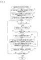
- FIG. 3 is a flowchart showing one portion of the operation in the FIG. 1 embodiment.
- FIG. 4 is a flowchart showing one portion of the operation of another embodiment of the present invention.
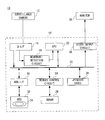
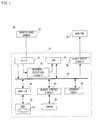
- a surveillance camera system 10 e.g., a first embodiment of the present invention, includes a surveillance camera 12 , a hard disk recorder 14 , and a monitor 38 .
- This surveillance camera system 10 is capable of compressing an image signal of an object photographed by the surveillance camera 12 so as to generate a compressed image signal, recording the generated compressed image signal into the hard disk recorder 14 , and expanding the recorded compressed image signal so as to be displayed on the monitor 38 .
- the surveillance camera 12 observes whether or not any movement is made to the photographed object such as an intruder, and etc., and applies to the hard disk recorder 14 the image signal corresponding to the object by every one field period as an analog signal.
- a D-I/F 16 In the hard disk recorder 14 , a D-I/F 16 , a CPU 20 , a JPEG 2000 CODEC 28 , a memory control circuit 24 , an HDD-I/F 30 , a video output circuit 36 are connected via a bus 22 to each other.
- a movement detection circuit 18 is connected to the D-I/F 16 and the CPU 20 .
- the HDD 32 containing a hard disk 34 is connected to a HDD-I/F 30 , and an SDRAM 26 to the memory control circuit 24 , respectively.
- the CPU 20 instructs the D-I/F 16 to fetch an analog image signal transmitted from the surveillance camera 12 .
- the CPU 20 may instruct the D-F/I 16 to fetch the analog image signal transmitted from the surveillance camera 12 in a thinning-out manner.
- the D-I/F 16 converts the fetched analog image signal into an analog image signal in a YUV format, that is, a Y signal, which is a luminance signal, and a color difference signal, which is a U (R-Y) signal, and a V (B-Y) signal, by a video decoder (not shown) provided inside the D-I/F 16 .
- the D-I/F 16 converts the analog image signal in the YUV format into a digital image signal in the YUV format by an A/D conversion circuit (not shown) provided inside the D-I/F 16 , and applies the converted digital image signal (hereinafter referred to as an “image signal”) to the movement detection circuit 18 , and the memory control circuit 24 , respectively.
- the movement detection circuit 18 extracts from the applied image signal the Y signal, which is the luminance signal, and finds a luminance change based on a size of the Y signal in the current screen, and the size of the Y signal in the screen one field preceding to the current screen.
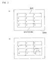
- the luminance change of the Y signal can be found by each block (3 ⁇ 4 blocks) dividing a detection area on the screen as shown in FIG. 2( a ), for example.
- the luminance change of the Y signal to be found is applied to the CPU 20 . It is noted that in place of the luminance change of the Y signal, a movement vector is found by each block, and the movement of the object may be detected from a size of the movement vector to be found.
- the CPU 20 determines whether or not the luminance change of the Y signal applied from the movement detection circuit 18 exceeds a detection threshold value set in advance. As a result, in a case of detecting the block having the luminance change exceeding the threshold value, the CPU 20 determines that there is the movement of the object in the block. Thus, a state in which it is determined that the luminance change of the Y signal found by the movement detection circuit 18 exceeds the detection threshold value is referred to as an internal alarm being detected. When the internal alarm is detected in a certain block, the CPU 20 specifies the block in which the internal alarm is detected. Next, toward the specified block, an ROI function of the JPEG 2000 is used so as to set an area to be noticed.
- the image signal applied from the D-I/F 16 to the memory control circuit 24 is written into the SDRAM 26 .
- the CPU 20 applies to the JPEG 2000 CODEC 28 an compression instruction of carrying out a compression at a compression rate stored in a register in advance.
- the JPEG CODEC 28 requests the memory control circuit 24 to read out the image signal.
- the JPEG CODEC 2000 compresses the image signal read-out from the SDRAM 26 by the memory control circuit 24 based on the compression instruction from the CPU 20 at the predetermined compression rate stored in advance in the register of the CPU 20 . This compression is performed according to a method defined by the JPEG 2000.
- the compression is carried out by the compression rate lower than the image of the area other than the area to be noticed in order to record the image of the area to be noticed in a high quality.
- the blocks 9 and 12 are set as the area to be noticed so that the CPU 20 instructs to compress the images in the blocks 9 and 12 at the compression rate lower than the images in the other blocks.
- the JPEG 2000 CODEC 28 compresses the image signal so as to generate the compressed image signal, and requests the memory control circuit 24 to write the generated compressed image signal. At the request of the JPEG 2000 CODEC 28 , the memory control circuit 24 writes the compressed image signal into the SDRAM 26 .
- the CPU 20 applies to the HDD-I/F 30 a recording instruction of the compressed image signal.
- the HDD-I/F 30 requests the memory control circuit 24 to read out the compressed image signal written in the SDRAM 26 .
- the memory control circuit 24 reads out the compressed image signal from the SDRAM 26 , and applies the read compressed image signal to the HDD 32 .
- the HDD 32 records the applied compressed image signal into the hard disk 34 in a file format or its own format. It is noted that a file of the compressed image signal recorded in the hard disk 34 is managed in the order of photographing.
- the CPU 20 instructs the HDD-I/F 30 to read out the compressed image signal.
- the HDD-I/F 30 to which the reading-out instruction is applied controls the HDD 32 , and sequentially reads out the compressed image signal from the hard disk 34 in the order of photographing.
- the CPU 20 instructs the memory control circuit 24 to write the read compressed image signal into the SDRAM 26 .
- the memory control circuit 24 writes the compressed image signal into the SDRAM 26 .
- the CPU 20 applies an expansion instruction to the JPEG 2000 CODEC 28 .
- the JPEG 2000 CODEC 28 to which the expansion instruction is applied requests the memory control circuit 24 to read out the compressed image signal, and the memory control circuit 24 reads out the compressed image signal written in the SDRAM 26 .
- the JPEG 2000 CODEC 28 expands the read compressed image signal according to a method defined by the JPEG 2000. In a case that the area to be noticed is set to the expanded image signal, the JPEG 2000 CODEC 28 expands the image of the area to be noticed, and the image other than the area to be noticed, using the compression rate at a time of compressing the both images, and generates the expanded image signal.
- the generated expanded image signal is applied to the memory control circuit 24 , and the memory control circuit writes the applied expanded image signal into the SDRAM 26 .
- the CPU 20 applies a processing instruction to the video output circuit 36 .
- the video output circuit 36 to which the processing instruction is applied requests the memory control circuit 24 to read out the expanded image signal by each one field period.
- the memory control circuit 24 reads out the expanded image signal from the SDRAM 26 , and applies the read expanded image signal to the video output circuit 36
- the video output circuit 36 encodes the applied expanded image signal into a composite image signal, and displays the encoded composite image signal on the screen of the monitor 38 .
- the image of the block to which the area to be noticed is set is rendered a high quality image compared to the images in the other blocks. That is, in a case of reproducing the image of FIG. 2( b ) on the monitor, the images in the blocks 9 and 12 have been rendered the high quality image compared to the images of the other blocks.
- a location of the internal alarm, and a detection threshold value of the internal alarm are set. More specifically, as shown in FIG. 2( a ), an arrangement of the block on the screen that finds the luminance change of the Y signal, and the detection threshold value, which is a reference of a size of the luminance change of the Y signal found by the movement detection circuit 18 are set.
- a step S 3 the compression rate used when compressing the image signal by the JPEG 2000 CODEC 28 is stored in the register of the CPU 20 .
- the compression rate there are an alarm compression rate used for compressing the image of a movement detection block, and a normal compression rate used for compressing the image of a movement-not-detected block.
- a step S 5 the CPU 20 sets the compression rate of the image of the entire areas of the screen to the normal compression rate.
- a step S 7 the CPU 20 determines whether or not a vertical synchronizing signal is occurred.
- the D-I/F 16 is instructed to fetch the image signal from the surveillance camera 12 in a step S 9 .
- the D-I/F 16 converts the fetched analog image signal into the image signal in a YUV format.
- the process of the step S 7 is repeated.
- the CPU 20 determines whether or not the internal alarm is detected. That is, the CPU 20 finds by each block by the movement detection circuit 18 a size of the luminance change from the size of the Y signal corresponding to the current screen, and the size of the Y signal corresponding to the screen one field preceding to the current screen. As a result, in a case that it is determined that the size of the luminance change to be found is larger than the stored detection threshold value, it is determined that the internal alarm is detected in the block. It is noted that in a case that the internal alarm is not detected, the CPU 20 instructs (step S 17 ) to compress the image of the entire area of the screen at the normal compression rate.
- the CPU 20 further specifies the block in a step S 13 . That is, it is indicated that the object has moved in the specified block.
- the CPU 20 sets the area to be noticed in a step S 15 . That is, the CPU 20 finds the luminance change of the Y signal by each block, and sets the area to be noticed to the block having the luminance change to be found exceeding the detection threshold value.
- the CPU 20 instructs the JPEG 2000 CODEC 28 to compress the image of the movement-detected block set as the area to be noticed at the alarm compression rate, and the image of the movement-not-detected block at the normal compression rate according to the method defined by the JPEG 2000, respectively.
- the alarm compression rate is set as the compression rate lower than the normal compression rate so that the compression is carried out in such a manner that the image of the area to be noticed is rendered the image of the high quality.
- a step S 19 the CPU 20 determines whether or not to end recording the image signal to the hard disk 34 .
- the compression recording process is ended.
- the process returns to the step S 7 .
- the process of a plurality of the blocks set in advance, even if the internal alarm is occurred in any block, it is possible to set the area to be noticed to the block in which the internal alarm is occurred, using the ROI function, thus possible to carry out the compression in such a manner that the image of the object moving on the screen is rendered the image of the high quality.
- FIG. 4 showing a flow of the compression recording process of the second embodiment, the description in the steps of the same operation as the first embodiment is omitted by attaching the same step numbers, and steps different from the first embodiment will be mainly described.
- the block in which the movement of the object is detected is rendered the area to be noticed, and the alarm compression rate is set (step S 15 ).
- the CPU 20 sets once again the compression rate of the image of the movement-not-detected block to a compression rate higher than the normal compression rate used in the first embodiment, and stores the same in the register.
- the CPU 20 instructs the JPEG 2000 CODEC 28 (step S 17 ) to compress the image of the movement-detected block in which the area to be noticed is set at the alarm compression rate, and the image of the movement-not-detected block at the compression rate set once again in the step S 21 , respectively, so as to generate the compressed image signal.
- the CPU 20 instructs the HDD-I/F 30 (step S 19 ) to record the generated compressed image signal into the hard disk 34 .
- an image size of the compressed image of the movement-detected block which is the area to be noticed, is approximately the same as the image size of the compressed image of the movement-detected block, which is the area to be noticed of the first embodiment.
- the compression rate of the image of the movement-not-detected block may be set once again.
- the CPU 20 instructs the JPEG 2000 CODEC 28 to compress the image of the movement-detected block including the specified object at the alarm compression rate, and the image of the movement-not-detected block at a compression rate higher than the normal compression rate, respectively.
- the JPEG 2000 CODEC 28 compresses the images so as to generate the compressed image signal, and requests the memory control circuit 24 to write the generated compressed image signal.
- the memory control circuit 24 writes the compressed image signal into the SDRAM 26 .
- the CPU 20 compares the image size of the compressed image including the specified object, and the image size of the compressed image having the image of all the blocks compressed at the normal compression rate. As a result, in a case that the image size of the compressed image including the specified object is larger, a CPU 60 instructs the JPEG 2000 CODEC once again to compress the image of the movement-detected block at the alarm compression rate, and the image of the movement-not-detected block at a compression rate higher than the normal compression rate, respectively.
- the compression is repeated until the image size of the compressed image that compressed the image including the specified object is rendered equal to the image size of the compressed image that compressed the image of all the blocks at the normal compression rate. Then, when the image size of the compressed image including the specified object is rendered equal to the image size of the compressed image of all the blocks, the CPU 60 applies the compressed image signal including the specified object to the HDD 32 , and allows the same to be recorded in the hard disk 34 .
- the increasing amount of the image size of the compressed image of the movement-detected block is rendered equal to the decreasing amount of the image size of the compressed image of the movement-not-detected block. Therefore, it is possible to render the image size of the entire compressed image equal to the image size of the compressed image that compressed the image of all the blocks at the normal compression rate. This enables to make the recording time period of the hard disk 34 yet longer.
- the image of the movement-detected block is compressed at the alarm compression rate, and the image of the movement-not-detected block at a compression rate taking into consideration the compression rate used at a time of the immediately preceding image compression, respectively, so as to generate the compressed image signal. That is, in a case that a compressed image size of the entire image formed of the movement-detected block and the movement-not-detected block is larger than a planned image size, in a subsequent compression, the compression rate is set to one level higher, for example, in such a manner that the image of the movement-not-detected block is further compressed.
- the compression rate is set to one level lower, for example, in such a manner that the image of the movement-not-detected block is not compressed than the current state.
- the CPU 60 applies the compressed image signal including the specified object to the HDD 32 , and allows the same to be recorded into the hard disk 34 . This enables to make the recording time period of the hard disk 34 longer, and a time period required for the image compression shorter.
- the image processing apparatus for compressing the plurality of screens of an image signal by each screen divides into a plurality of blocks by each screen so as to find the size of the luminance change of the Y signal found by the movement detection circuit 18 by each block. Furthermore, from the size of the luminance change of the Y signal to be found, the object with movement (specified object) is detected, and the block in which the object with movement exists is specified.
- the JPEG 2000 CODEC 28 is instructed to compress the first portion image, which is the image of the block in which the object with movement is detected, is compressed at the alarm compression rate (first compression rate), and the second portion image, which is the image of the block in which the object with movement is not detected, is compressed at the normal compression rate (second compression rate), which is a higher compression rate than the alarm compression rate.
- first compression rate the alarm compression rate
- second compression rate the normal compression rate
- the entire one screen in which the object with movement does not exist is compressed at the same compression rate as the normal compression rate (third compression rate).
- the entire one screen being compressed at the normal compression rate, which is a higher compression rate than the alarm compression rate, a recording time period of a hard disk 34 is rendered longer, thus possible to put the hard disk 34 to an effective use.
- the second portion image is compressed at a compression rate (fourth compression rate) higher than the normal compression rate. This enables to render the compressed image size of the second portion image smaller, thus possible to put the hard disk to an effective use.
- the fourth compression rate at which the image size of one screen of the compressed image signal in which an object with movement exists, and the image size of one screen of the compressed image signal in which no object with movement exists are rendered the same is found, and one screen of the second image portion in which the object with movement exists is compressed at the fourth compression rate to be found.
Abstract
An image processing apparatus is adapted to a surveillance camera system, and a CPU included in the surveillance camera system divides a plurality of continuous screens of an image signal into a plurality of blocks by each screen, and detects a specific object, which is an object with movement, from a luminance change of a Y signal found by a movement detection circuit. In addition, the CPU specifies the block in which a movement of the object is detected, and sets the specified block as an area to be noticed by taking advantage of an ROI function of a JPEG 2000. Next, a JPEG 2000 CODEC is instructed to compress an image of a movement-detected block into a high quality image by an alarm compression rate, and compress the image of a movement-not-detected block by a normal compression rate having a higher compression rate than the alarm compression rate. This enables to make a compression in such a manner that the image of the object with movement is rendered a higher quality image compared to the image of an object without movement.
Description
- 1. Field of the Invention
- The present invention relates to an image processing apparatus. More specifically, the present invention relates to an image processing apparatus adapted to a surveillance camera system, and separately compressing a plurality of continuous screens of an image signal.
- 2. Description of the Prior Art
- One example of a conventional image processing apparatus is disclosed in Japanese Patent Laying-open No. 2001-230947. This image processing apparatus sets an area to be noticed by using an ROI (Region Of Interest) function of a
JPEG 2000, and carries out a compression process in such a manner that an image of the set area to be noticed is rendered a higher quality image than the images in the other areas. - However, in the prior art, the area to be noticed is fixed, and therefore, in a case of an object with movement, there is a problem that it is not possible to compress the object with movement in such a manner that the image is rendered the high quality image.
- Therefore, it is a primary object of the present invention to provide a novel image processing apparatus. It is another object of the present invention to provide an image processing apparatus capable of making a compression in such a manner that an image is rendered a high quality image even in a case of the object with movement.
- The present invention is an image processing apparatus separately compressing a plurality of continuous screens of an image signal, and comprises: a detector for detecting a specified object with movement based on said plurality of screens of image signals; a first validater for validating a first compression rate regarding a first portion image corresponding to said specified object, of one screen in which said specified object exists; and a second validater for validating a second compression rate higher than said first compression rate regarding a second portion image corresponding to an object other than said specified object, of one screen in which said specified object exists.
- The image processing apparatus separately compresses a plurality of continuous screens of an image signal one screen by one screen, and detects a specified object with movement based on the image signal of each screen. Furthermore, of one screen in which the specified object exists, regarding a first portion image corresponding to the specified object, a compression is carried out by a first compression rate. In addition, regarding a second portion image corresponding to the object other than the specified object in the same screen, a compression is carried out by a second compression rate higher than the first compression rate. In this case, it is possible to carry out the compression in such a manner that the image corresponding to the object with movement is rendered a higher quality image compared to the image corresponding to the object other than the specified object.
- Preferably, regarding one screen in which the specified object does not exist, a compression is carried out by a third compression rate, which is the same compression rate as the second compression rate. In this case, it is possible to carry out the compression by the same compression rate across the entire screen so that a hard disk is put to an effective use.
- Preferably, regarding a second portion image, a compression is carried out by a fourth compression rate, which is a higher compression rate than the second compression rate. In this case, an image size of the second portion image is rendered smaller than the image size in a case of being compressed by the second compression rate so that a hard disk is put to an effective use.
- Preferably, a fourth compression rate is found in such a manner that an image size of one screen of a compressed image signal in which the specified object exists, and the image size of one screen of the compressed image signal in which the specified object does not exist satisfy a predetermined condition, and the second portion image is compressed by the found fourth compression rate.
- Preferably, a fourth compression rate is found in such a manner that an image size of one screen of a compressed image signal in which the specified object exists conforms to the image size of one screen of the compressed image signal in which the specified object does not exist, and one screen of the second portion image in which the specified object exists is compressed by the found fourth compression rate. In this case, it is possible to dissolve an increasing amount of the image size in a case of compressing the first portion image by the first compression rate by a decreasing amount of the image size in a case of compressing the second portion image by the fourth compression rate. This enables to keep constant one screen of the compressed image size in which the object with movement exists.
- Preferably, the plurality of continuous screens of an image signal are image signals output from a camera.
- According to the present invention, in a case that an object moves in a plurality of continuous screens, a movement of the object is detected, and the compression rate is changeable according to the detected movement. This enables to carry out a compression in such a manner that the object with movement is rendered a high quality image.
- The above described objects and other objects, features, aspects and advantages of the present invention will become more apparent from the following detailed description of the present invention when taken in conjunction with the accompanying drawings.
- FIG. 1 is a block diagram showing one embodiment of the present invention;
- FIG. 2 is an illustrative view showing a block for detecting a movement of an object in the FIG. 1 embodiment;
- FIG. 3 is a flowchart showing one portion of the operation in the FIG. 1 embodiment; and
- FIG. 4 is a flowchart showing one portion of the operation of another embodiment of the present invention.
- Referring to FIG. 1, a
surveillance camera system 10, e.g., a first embodiment of the present invention, includes asurveillance camera 12, ahard disk recorder 14, and amonitor 38. Thissurveillance camera system 10 is capable of compressing an image signal of an object photographed by thesurveillance camera 12 so as to generate a compressed image signal, recording the generated compressed image signal into thehard disk recorder 14, and expanding the recorded compressed image signal so as to be displayed on themonitor 38. - The
surveillance camera 12 observes whether or not any movement is made to the photographed object such as an intruder, and etc., and applies to thehard disk recorder 14 the image signal corresponding to the object by every one field period as an analog signal. - In the
hard disk recorder 14, a D-I/F16, aCPU 20, aJPEG 2000CODEC 28, amemory control circuit 24, an HDD-I/F 30, avideo output circuit 36 are connected via abus 22 to each other. Amovement detection circuit 18 is connected to the D-I/F 16 and theCPU 20. TheHDD 32 containing ahard disk 34 is connected to a HDD-I/F 30, and anSDRAM 26 to thememory control circuit 24, respectively. - The
CPU 20 instructs the D-I/F 16 to fetch an analog image signal transmitted from thesurveillance camera 12. TheCPU 20 may instruct the D-F/I 16 to fetch the analog image signal transmitted from thesurveillance camera 12 in a thinning-out manner. The D-I/F 16 converts the fetched analog image signal into an analog image signal in a YUV format, that is, a Y signal, which is a luminance signal, and a color difference signal, which is a U (R-Y) signal, and a V (B-Y) signal, by a video decoder (not shown) provided inside the D-I/F 16. Next, the D-I/F 16 converts the analog image signal in the YUV format into a digital image signal in the YUV format by an A/D conversion circuit (not shown) provided inside the D-I/F 16, and applies the converted digital image signal (hereinafter referred to as an “image signal”) to themovement detection circuit 18, and thememory control circuit 24, respectively. - The
movement detection circuit 18 extracts from the applied image signal the Y signal, which is the luminance signal, and finds a luminance change based on a size of the Y signal in the current screen, and the size of the Y signal in the screen one field preceding to the current screen. The luminance change of the Y signal can be found by each block (3×4 blocks) dividing a detection area on the screen as shown in FIG. 2(a), for example. The luminance change of the Y signal to be found is applied to theCPU 20. It is noted that in place of the luminance change of the Y signal, a movement vector is found by each block, and the movement of the object may be detected from a size of the movement vector to be found. - Next, the
CPU 20 determines whether or not the luminance change of the Y signal applied from themovement detection circuit 18 exceeds a detection threshold value set in advance. As a result, in a case of detecting the block having the luminance change exceeding the threshold value, theCPU 20 determines that there is the movement of the object in the block. Thus, a state in which it is determined that the luminance change of the Y signal found by themovement detection circuit 18 exceeds the detection threshold value is referred to as an internal alarm being detected. When the internal alarm is detected in a certain block, theCPU 20 specifies the block in which the internal alarm is detected. Next, toward the specified block, an ROI function of theJPEG 2000 is used so as to set an area to be noticed. In a case that the screen is developed from FIG. 2(a) to Figure (b), for example, there are the movements inblocks blocks - On the other hand, the image signal applied from the D-I/
F 16 to thememory control circuit 24 is written into theSDRAM 26. - The
CPU 20 applies to theJPEG 2000CODEC 28 an compression instruction of carrying out a compression at a compression rate stored in a register in advance. In receipt of the compression instruction, theJPEG CODEC 28 requests thememory control circuit 24 to read out the image signal. Next, theJPEG CODEC 2000 compresses the image signal read-out from theSDRAM 26 by thememory control circuit 24 based on the compression instruction from theCPU 20 at the predetermined compression rate stored in advance in the register of theCPU 20. This compression is performed according to a method defined by theJPEG 2000. At this time, in a case that the area to be noticed is set to the image signal to be compressed, the compression is carried out by the compression rate lower than the image of the area other than the area to be noticed in order to record the image of the area to be noticed in a high quality. In a case of FIG. 2(b), for example, theblocks CPU 20 instructs to compress the images in theblocks - The
JPEG 2000CODEC 28 compresses the image signal so as to generate the compressed image signal, and requests thememory control circuit 24 to write the generated compressed image signal. At the request of theJPEG 2000CODEC 28, thememory control circuit 24 writes the compressed image signal into theSDRAM 26. - Next, the
CPU 20 applies to the HDD-I/F 30 a recording instruction of the compressed image signal. In accordance with the recording instruction from theCPU 20, the HDD-I/F 30 requests thememory control circuit 24 to read out the compressed image signal written in theSDRAM 26. Thememory control circuit 24 reads out the compressed image signal from theSDRAM 26, and applies the read compressed image signal to theHDD 32. TheHDD 32 records the applied compressed image signal into thehard disk 34 in a file format or its own format. It is noted that a file of the compressed image signal recorded in thehard disk 34 is managed in the order of photographing. - Next, a case of reproducing the compressed image signal recorded in the
hard disk 34 will be described. First, theCPU 20 instructs the HDD-I/F 30 to read out the compressed image signal. The HDD-I/F 30 to which the reading-out instruction is applied controls theHDD 32, and sequentially reads out the compressed image signal from thehard disk 34 in the order of photographing. - Then, the
CPU 20 instructs thememory control circuit 24 to write the read compressed image signal into theSDRAM 26. In receipt of the writing instruction, thememory control circuit 24 writes the compressed image signal into theSDRAM 26. - Next, the
CPU 20 applies an expansion instruction to theJPEG 2000CODEC 28. TheJPEG 2000CODEC 28 to which the expansion instruction is applied requests thememory control circuit 24 to read out the compressed image signal, and thememory control circuit 24 reads out the compressed image signal written in theSDRAM 26. TheJPEG 2000CODEC 28 expands the read compressed image signal according to a method defined by theJPEG 2000. In a case that the area to be noticed is set to the expanded image signal, theJPEG 2000CODEC 28 expands the image of the area to be noticed, and the image other than the area to be noticed, using the compression rate at a time of compressing the both images, and generates the expanded image signal. The generated expanded image signal is applied to thememory control circuit 24, and the memory control circuit writes the applied expanded image signal into theSDRAM 26. - The
CPU 20 applies a processing instruction to thevideo output circuit 36. Thevideo output circuit 36 to which the processing instruction is applied requests thememory control circuit 24 to read out the expanded image signal by each one field period. Thememory control circuit 24 reads out the expanded image signal from theSDRAM 26, and applies the read expanded image signal to thevideo output circuit 36 - The
video output circuit 36 encodes the applied expanded image signal into a composite image signal, and displays the encoded composite image signal on the screen of themonitor 38. At this time, the image of the block to which the area to be noticed is set is rendered a high quality image compared to the images in the other blocks. That is, in a case of reproducing the image of FIG. 2(b) on the monitor, the images in theblocks - Next, regarding a flow of a compression recording process of the image signal in this
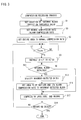
surveillance camera system 10, descriptions will be given using FIG. 3. - First, in a step S 1, a location of the internal alarm, and a detection threshold value of the internal alarm are set. More specifically, as shown in FIG. 2(a), an arrangement of the block on the screen that finds the luminance change of the Y signal, and the detection threshold value, which is a reference of a size of the luminance change of the Y signal found by the
movement detection circuit 18 are set. - Next, in a step S 3, the compression rate used when compressing the image signal by the
JPEG 2000CODEC 28 is stored in the register of theCPU 20. Regarding the compression rate, there are an alarm compression rate used for compressing the image of a movement detection block, and a normal compression rate used for compressing the image of a movement-not-detected block. - Furthermore, in a step S 5, the
CPU 20 sets the compression rate of the image of the entire areas of the screen to the normal compression rate. - Next, in a step S 7, the
CPU 20 determines whether or not a vertical synchronizing signal is occurred. In a case that the vertical synchronizing signal is occurred, the D-I/F 16 is instructed to fetch the image signal from thesurveillance camera 12 in a step S9. The D-I/F 16 converts the fetched analog image signal into the image signal in a YUV format. On the other hand, in a case that no vertical synchronizing signal is occurred, the process of the step S7 is repeated. - Next, in a step S 11, the
CPU 20 determines whether or not the internal alarm is detected. That is, theCPU 20 finds by each block by the movement detection circuit 18 a size of the luminance change from the size of the Y signal corresponding to the current screen, and the size of the Y signal corresponding to the screen one field preceding to the current screen. As a result, in a case that it is determined that the size of the luminance change to be found is larger than the stored detection threshold value, it is determined that the internal alarm is detected in the block. It is noted that in a case that the internal alarm is not detected, theCPU 20 instructs (step S17) to compress the image of the entire area of the screen at the normal compression rate. - Next, in a case that the internal alarm is detected, the
CPU 20 further specifies the block in a step S13. That is, it is indicated that the object has moved in the specified block. - Then, using the ROI function of the
JPEG 2000, theCPU 20 sets the area to be noticed in a step S15. That is, theCPU 20 finds the luminance change of the Y signal by each block, and sets the area to be noticed to the block having the luminance change to be found exceeding the detection threshold value. - In the step S 17, the
CPU 20 instructs theJPEG 2000CODEC 28 to compress the image of the movement-detected block set as the area to be noticed at the alarm compression rate, and the image of the movement-not-detected block at the normal compression rate according to the method defined by theJPEG 2000, respectively. At this time, the alarm compression rate is set as the compression rate lower than the normal compression rate so that the compression is carried out in such a manner that the image of the area to be noticed is rendered the image of the high quality. - Then, in a step S 19, the
CPU 20 determines whether or not to end recording the image signal to thehard disk 34. In a case of ending the recording, the compression recording process is ended. On the other hand, in a case that there are still the image signals to be recorded, the process returns to the step S7. In this case, of a plurality of the blocks set in advance, even if the internal alarm is occurred in any block, it is possible to set the area to be noticed to the block in which the internal alarm is occurred, using the ROI function, thus possible to carry out the compression in such a manner that the image of the object moving on the screen is rendered the image of the high quality. - Next, a second embodiment of the
surveillance camera system 10 will be described. A block diagram and an illustrative view of the second embodiment are the same as FIG. 1 and FIG. 2 of the first embodiment so that its descriptions are omitted. In addition, in FIG. 4 showing a flow of the compression recording process of the second embodiment, the description in the steps of the same operation as the first embodiment is omitted by attaching the same step numbers, and steps different from the first embodiment will be mainly described. - Similar to the case of the first embodiment, the block in which the movement of the object is detected is rendered the area to be noticed, and the alarm compression rate is set (step S 15). Next, in a step S21, the
CPU 20 sets once again the compression rate of the image of the movement-not-detected block to a compression rate higher than the normal compression rate used in the first embodiment, and stores the same in the register. - Similar to the case of the first embodiment, the
CPU 20 instructs theJPEG 2000 CODEC 28 (step S17) to compress the image of the movement-detected block in which the area to be noticed is set at the alarm compression rate, and the image of the movement-not-detected block at the compression rate set once again in the step S21, respectively, so as to generate the compressed image signal. Next, theCPU 20 instructs the HDD-I/F 30 (step S19) to record the generated compressed image signal into thehard disk 34. - In this case, an image size of the compressed image of the movement-detected block, which is the area to be noticed, is approximately the same as the image size of the compressed image of the movement-detected block, which is the area to be noticed of the first embodiment. However, it is possible to further minimize the image size of the compressed image of the movement-not-detected block than the image size of the compressed image of the movement-not-detected block of the first embodiment. Therefore, it is possible to make a recording time period of the hard disk longer.
- It is noted that in the step S 21, similar to the case that the decreasing amount of the image size in a case of compressing the image of the movement-not-detected block is dissolved by the increasing amount of the image size in a case of compressing the image of the movement-detected block at the alarm compression rate, the compression rate of the image of the movement-not-detected block may be set once again.
- More specifically, the
CPU 20 instructs theJPEG 2000CODEC 28 to compress the image of the movement-detected block including the specified object at the alarm compression rate, and the image of the movement-not-detected block at a compression rate higher than the normal compression rate, respectively. TheJPEG 2000CODEC 28 compresses the images so as to generate the compressed image signal, and requests thememory control circuit 24 to write the generated compressed image signal. Thememory control circuit 24 writes the compressed image signal into theSDRAM 26. - Next, the
CPU 20 compares the image size of the compressed image including the specified object, and the image size of the compressed image having the image of all the blocks compressed at the normal compression rate. As a result, in a case that the image size of the compressed image including the specified object is larger, a CPU 60 instructs theJPEG 2000 CODEC once again to compress the image of the movement-detected block at the alarm compression rate, and the image of the movement-not-detected block at a compression rate higher than the normal compression rate, respectively. - Thus, the compression is repeated until the image size of the compressed image that compressed the image including the specified object is rendered equal to the image size of the compressed image that compressed the image of all the blocks at the normal compression rate. Then, when the image size of the compressed image including the specified object is rendered equal to the image size of the compressed image of all the blocks, the CPU 60 applies the compressed image signal including the specified object to the
HDD 32, and allows the same to be recorded in thehard disk 34. - In this case, the increasing amount of the image size of the compressed image of the movement-detected block is rendered equal to the decreasing amount of the image size of the compressed image of the movement-not-detected block. Therefore, it is possible to render the image size of the entire compressed image equal to the image size of the compressed image that compressed the image of all the blocks at the normal compression rate. This enables to make the recording time period of the
hard disk 34 yet longer. - It is noted that it may be possible that the image of the movement-detected block is compressed at the alarm compression rate, and the image of the movement-not-detected block at a compression rate taking into consideration the compression rate used at a time of the immediately preceding image compression, respectively, so as to generate the compressed image signal. That is, in a case that a compressed image size of the entire image formed of the movement-detected block and the movement-not-detected block is larger than a planned image size, in a subsequent compression, the compression rate is set to one level higher, for example, in such a manner that the image of the movement-not-detected block is further compressed. In contrary, in a case that the compressed image size of the entire image is smaller than the planned image size, in a subsequent compression, the compression rate is set to one level lower, for example, in such a manner that the image of the movement-not-detected block is not compressed than the current state. After this, the CPU 60 applies the compressed image signal including the specified object to the
HDD 32, and allows the same to be recorded into thehard disk 34. This enables to make the recording time period of thehard disk 34 longer, and a time period required for the image compression shorter. - As understood from the above descriptions, the image processing apparatus for compressing the plurality of screens of an image signal by each screen divides into a plurality of blocks by each screen so as to find the size of the luminance change of the Y signal found by the
movement detection circuit 18 by each block. Furthermore, from the size of the luminance change of the Y signal to be found, the object with movement (specified object) is detected, and the block in which the object with movement exists is specified. Next, of one screen in which the object with movement exists, theJPEG 2000CODEC 28 is instructed to compress the first portion image, which is the image of the block in which the object with movement is detected, is compressed at the alarm compression rate (first compression rate), and the second portion image, which is the image of the block in which the object with movement is not detected, is compressed at the normal compression rate (second compression rate), which is a higher compression rate than the alarm compression rate. This enables to carry out a compression in such a manner that the first portion image is rendered the higher quality image compared to the second portion image. - The entire one screen in which the object with movement does not exist is compressed at the same compression rate as the normal compression rate (third compression rate). In this case, as a result of the entire one screen being compressed at the normal compression rate, which is a higher compression rate than the alarm compression rate, a recording time period of a
hard disk 34 is rendered longer, thus possible to put thehard disk 34 to an effective use. - The second portion image is compressed at a compression rate (fourth compression rate) higher than the normal compression rate. This enables to render the compressed image size of the second portion image smaller, thus possible to put the hard disk to an effective use.
- The fourth compression rate at which the image size of one screen of the compressed image signal in which an object with movement exists, and the image size of one screen of the compressed image signal in which no object with movement exists satisfy a predetermined size condition is found, and the second portion image is compressed by the fourth compression rate to be found.
- The fourth compression rate at which the image size of one screen of the compressed image signal in which an object with movement exists, and the image size of one screen of the compressed image signal in which no object with movement exists are rendered the same is found, and one screen of the second image portion in which the object with movement exists is compressed at the fourth compression rate to be found. This makes it possible to dissolve the increasing amount of the image size in a case of compressing the first portion image at the alarm compression rate by the decreasing amount of the image size in a case of compressing the second portion image at the fourth compression rate. Thus, it is possible to maintain constant one screen of the compressed image size in which the object with movement exists.
- Although the present invention has been described and illustrated in detail, it is clearly understood that the same is by way of illustration and example only and is not to be taken by way of limitation, the spirit and scope of the present invention being limited only by the terms of the appended claims.
Claims (7)
1. An image processing apparatus separately compressing a plurality of continuous screens of an image signal, comprising:
a detector for detecting a specified object with movement based on said plurality of screens of an image signal;
a first validater for validating a first compression rate regarding a first portion image corresponding to said specified object, of one screen in which said specified object exists; and
a second validater for validating a second compression rate higher than said first compression rate regarding a second portion image corresponding to an object other than said specified object, of one screen in which said specified object exists.
2. An image processing apparatus according to claim 1 , further comprising
a third validater for validating a third compression rate equal to said second compression rate regarding one screen in which said specified object does not exist.
3. An image processing apparatus according to claim 1 , further comprising
a fourth validater for validating a fourth compression rate higher than said second compression rate regarding said second portion image.
4. An image processing apparatus according to claim 3 , wherein
said fourth compression rate is a compression rate having a predetermined size condition satisfied between one screen of a compressed image signal in which said specified object exists, and one screen of the compressed image signal in which said specified object does not exists.
5. An image processing apparatus according to claim 4 , wherein
said predetermined size condition is a condition that the both sizes conform with each other.
6. An image processing apparatus according to any one of claims 1 to 5 , wherein
said plurality of continuous screens of an image signal are image signals output from a camera.
7. An image processing method separately compressing a plurality of continuous screens of an image signal, comprising steps of:
(a) detecting a specified object with movement based on said plurality of continuous screens of an image signal;
(b) validating a first compression rate regarding a first portion image corresponding to said specified object, of one screen in which said specified object exists; and
(c) validating a second compression rate higher than said first compression rate regarding a second portion image corresponding to an object other than said specified object, of one screen in which said specified object exists.
Applications Claiming Priority (2)
| Application Number | Priority Date | Filing Date | Title |
|---|---|---|---|
| JP2002363238A JP2004200739A (en) | 2002-12-16 | 2002-12-16 | Image processor |
| JP2002-363238 | 2002-12-16 |
Publications (2)
| Publication Number | Publication Date |
|---|---|
| US20040179110A1 true US20040179110A1 (en) | 2004-09-16 |
| US7421134B2 US7421134B2 (en) | 2008-09-02 |
Family
ID=32761433
Family Applications (1)
| Application Number | Title | Priority Date | Filing Date |
|---|---|---|---|
| US10/734,204 Expired - Fee Related US7421134B2 (en) | 2002-12-16 | 2003-12-15 | Image processing apparatus and method for moving object-adaptive compression |
Country Status (3)
| Country | Link |
|---|---|
| US (1) | US7421134B2 (en) |
| JP (1) | JP2004200739A (en) |
| CN (1) | CN100367772C (en) |
Cited By (10)
| Publication number | Priority date | Publication date | Assignee | Title |
|---|---|---|---|---|
| EP1677541A2 (en) * | 2004-12-30 | 2006-07-05 | ASTRA Gesellschaft für Asset Management mbH & Co. KG | Method and device for transmission of image data |
| GB2424337A (en) * | 2005-03-14 | 2006-09-20 | Avermedia Tech Inc | Surveillance system storing motion video data at a higher resolution or frame rate |
| US20060233419A1 (en) * | 2005-03-30 | 2006-10-19 | Fuji Photo Film Co., Ltd. | Image display control method, image display control program, image data recording method and computer-readable medium |
| US20060274957A1 (en) * | 2005-06-01 | 2006-12-07 | Norio Suzuki | Information transmitting method for a remote operating system |
| US20070212043A1 (en) * | 2006-03-10 | 2007-09-13 | Fujifilm Corporation | Digital imaging apparatus with camera shake compensation and adaptive sensitivity switching function |
| US20090129672A1 (en) * | 2007-11-15 | 2009-05-21 | Camp Jr William O | System and method for generating a photograph with variable image quality |
| US9282330B1 (en) * | 2011-07-13 | 2016-03-08 | Google Inc. | Method and apparatus for data compression using content-based features |
| EP3713214A4 (en) * | 2017-11-14 | 2020-09-23 | Sony Semiconductor Solutions Corporation | Imaging device, imaging method, and imaging system |
| US10917648B2 (en) | 2018-01-31 | 2021-02-09 | Canon Kabushiki Kaisha | Image processing apparatus, image processing method, and non-transitory computer-readable storage medium |
| US11270412B2 (en) * | 2019-10-31 | 2022-03-08 | Apical Limited | Image signal processor, method, and system for environmental mapping |
Families Citing this family (9)
| Publication number | Priority date | Publication date | Assignee | Title |
|---|---|---|---|---|
| US8024768B2 (en) * | 2005-09-15 | 2011-09-20 | Penthera Partners, Inc. | Broadcasting video content to devices having different video presentation capabilities |
| JP2007221328A (en) * | 2006-02-15 | 2007-08-30 | Sony Corp | Command system, imaging apparatus, command apparatus, imaging processing method, command processing method, and program |
| JP2008311831A (en) * | 2007-06-13 | 2008-12-25 | Panasonic Corp | Moving image communication equipment, moving image communication system, and semiconductor integrated circuit for moving image communication |
| JP5062407B2 (en) * | 2007-07-19 | 2012-10-31 | 富士フイルム株式会社 | Image processing apparatus, image processing method, and program |
| JP2010136032A (en) | 2008-12-04 | 2010-06-17 | Hitachi Ltd | Video monitoring system |
| JP5361618B2 (en) * | 2009-09-04 | 2013-12-04 | キヤノン株式会社 | Image processing apparatus and control method thereof |
| US8650591B2 (en) * | 2010-03-09 | 2014-02-11 | Yolanda Prieto | Video enabled digital devices for embedding user data in interactive applications |
| CN102238374B (en) * | 2010-04-21 | 2016-08-24 | 腾讯科技(深圳)有限公司 | The method and apparatus that view data is compressed coding |
| WO2012026122A1 (en) * | 2010-08-26 | 2012-03-01 | パナソニック株式会社 | Imaging device |
Citations (8)
| Publication number | Priority date | Publication date | Assignee | Title |
|---|---|---|---|---|
| US5956088A (en) * | 1995-11-21 | 1999-09-21 | Imedia Corporation | Method and apparatus for modifying encoded digital video for improved channel utilization |
| US20020080878A1 (en) * | 2000-10-12 | 2002-06-27 | Webcast Technologies, Inc. | Video apparatus and method for digital video enhancement |
| US20020109780A1 (en) * | 2001-02-14 | 2002-08-15 | Sanyo Electric Co., Ltd. | Digital camera |
| US6917384B1 (en) * | 1999-06-14 | 2005-07-12 | Canon Kabushiki Kaisha | Image sensing apparatus, method and recording medium storing program for method of setting plural photographic modes and variable specific region of image sensing, and providing mode specific compression of image data in the specific region |
| US6937773B1 (en) * | 1999-10-20 | 2005-08-30 | Canon Kabushiki Kaisha | Image encoding method and apparatus |
| US6968119B1 (en) * | 1998-10-19 | 2005-11-22 | Sanyo Electric Co., Ltd. | Electronic camera with compression |
| US6980703B2 (en) * | 2001-02-08 | 2005-12-27 | Kabushiki Kaisha Toshiba | Information storage apparatus and article of manufacture |
| US7257264B2 (en) * | 2001-08-29 | 2007-08-14 | Canon Kabushiki Kaisha | Image processing apparatus and method for compression-encoding image area information |
Family Cites Families (12)
| Publication number | Priority date | Publication date | Assignee | Title |
|---|---|---|---|---|
| JPH0575987A (en) * | 1991-09-17 | 1993-03-26 | Matsushita Electric Ind Co Ltd | Method for detecting action area of dynamic image signal and high efficiency coder |
| JPH07288806A (en) * | 1994-04-20 | 1995-10-31 | Hitachi Ltd | Moving image communication system |
| JP3258840B2 (en) * | 1994-12-27 | 2002-02-18 | シャープ株式会社 | Video encoding device and region extraction device |
| JPH09200764A (en) * | 1996-01-16 | 1997-07-31 | Canon Inc | Encoder |
| JPH1070716A (en) * | 1996-08-27 | 1998-03-10 | Toyo Commun Equip Co Ltd | Moving picture compressing device |
| JPH10271515A (en) * | 1997-03-26 | 1998-10-09 | Sanyo Electric Co Ltd | Noticed area tracing method, noticed area tracing device using the method and image coding method |
| JP2003501902A (en) | 1999-05-27 | 2003-01-14 | コーニンクレッカ フィリップス エレクトロニクス エヌ ヴィ | Video signal encoding |
| JP2001036901A (en) * | 1999-07-15 | 2001-02-09 | Canon Inc | Device and method for processing image and memory medium |
| US6314452B1 (en) * | 1999-08-31 | 2001-11-06 | Rtimage, Ltd. | System and method for transmitting a digital image over a communication network |
| JP3957937B2 (en) * | 1999-12-21 | 2007-08-15 | キヤノン株式会社 | Image processing apparatus and method, and storage medium |
| JP2001230947A (en) * | 2000-02-18 | 2001-08-24 | Canon Inc | Device and method for processing image |
| JP4370726B2 (en) * | 2001-02-15 | 2009-11-25 | 株式会社ニコン | Electronic camera and image processing program |
-
2002
- 2002-12-16 JP JP2002363238A patent/JP2004200739A/en active Pending
-
2003
- 2003-12-12 CN CNB2003101185492A patent/CN100367772C/en not_active Expired - Fee Related
- 2003-12-15 US US10/734,204 patent/US7421134B2/en not_active Expired - Fee Related
Patent Citations (8)
| Publication number | Priority date | Publication date | Assignee | Title |
|---|---|---|---|---|
| US5956088A (en) * | 1995-11-21 | 1999-09-21 | Imedia Corporation | Method and apparatus for modifying encoded digital video for improved channel utilization |
| US6968119B1 (en) * | 1998-10-19 | 2005-11-22 | Sanyo Electric Co., Ltd. | Electronic camera with compression |
| US6917384B1 (en) * | 1999-06-14 | 2005-07-12 | Canon Kabushiki Kaisha | Image sensing apparatus, method and recording medium storing program for method of setting plural photographic modes and variable specific region of image sensing, and providing mode specific compression of image data in the specific region |
| US6937773B1 (en) * | 1999-10-20 | 2005-08-30 | Canon Kabushiki Kaisha | Image encoding method and apparatus |
| US20020080878A1 (en) * | 2000-10-12 | 2002-06-27 | Webcast Technologies, Inc. | Video apparatus and method for digital video enhancement |
| US6980703B2 (en) * | 2001-02-08 | 2005-12-27 | Kabushiki Kaisha Toshiba | Information storage apparatus and article of manufacture |
| US20020109780A1 (en) * | 2001-02-14 | 2002-08-15 | Sanyo Electric Co., Ltd. | Digital camera |
| US7257264B2 (en) * | 2001-08-29 | 2007-08-14 | Canon Kabushiki Kaisha | Image processing apparatus and method for compression-encoding image area information |
Cited By (14)
| Publication number | Priority date | Publication date | Assignee | Title |
|---|---|---|---|---|
| EP1677541A2 (en) * | 2004-12-30 | 2006-07-05 | ASTRA Gesellschaft für Asset Management mbH & Co. KG | Method and device for transmission of image data |
| GB2424337A (en) * | 2005-03-14 | 2006-09-20 | Avermedia Tech Inc | Surveillance system storing motion video data at a higher resolution or frame rate |
| US20060233419A1 (en) * | 2005-03-30 | 2006-10-19 | Fuji Photo Film Co., Ltd. | Image display control method, image display control program, image data recording method and computer-readable medium |
| US20060274957A1 (en) * | 2005-06-01 | 2006-12-07 | Norio Suzuki | Information transmitting method for a remote operating system |
| US20070212043A1 (en) * | 2006-03-10 | 2007-09-13 | Fujifilm Corporation | Digital imaging apparatus with camera shake compensation and adaptive sensitivity switching function |
| US7787757B2 (en) | 2006-03-10 | 2010-08-31 | Fujifilm Corporation | Digital imaging apparatus with camera shake compensation and adaptive sensitivity switching function |
| WO2009064514A1 (en) * | 2007-11-15 | 2009-05-22 | Sony Ericsson Mobile Communications Ab | System and method for generating a photograph with variable image quality |
| US20090129672A1 (en) * | 2007-11-15 | 2009-05-21 | Camp Jr William O | System and method for generating a photograph with variable image quality |
| US8045799B2 (en) | 2007-11-15 | 2011-10-25 | Sony Ericsson Mobile Communications Ab | System and method for generating a photograph with variable image quality |
| US9282330B1 (en) * | 2011-07-13 | 2016-03-08 | Google Inc. | Method and apparatus for data compression using content-based features |
| EP3713214A4 (en) * | 2017-11-14 | 2020-09-23 | Sony Semiconductor Solutions Corporation | Imaging device, imaging method, and imaging system |
| US11514581B2 (en) | 2017-11-14 | 2022-11-29 | Sony Semiconductor Solutions Corporation | Image capturing device, image capturing method, and image capturing system |
| US10917648B2 (en) | 2018-01-31 | 2021-02-09 | Canon Kabushiki Kaisha | Image processing apparatus, image processing method, and non-transitory computer-readable storage medium |
| US11270412B2 (en) * | 2019-10-31 | 2022-03-08 | Apical Limited | Image signal processor, method, and system for environmental mapping |
Also Published As
| Publication number | Publication date |
|---|---|
| US7421134B2 (en) | 2008-09-02 |
| CN1509071A (en) | 2004-06-30 |
| CN100367772C (en) | 2008-02-06 |
| JP2004200739A (en) | 2004-07-15 |
Similar Documents
| Publication | Publication Date | Title |
|---|---|---|
| US7421134B2 (en) | Image processing apparatus and method for moving object-adaptive compression | |
| US7542613B2 (en) | Image processing apparatus | |
| US7035483B2 (en) | Image search apparatus | |
| JP4075748B2 (en) | Image recording device | |
| US7146052B2 (en) | Image processing apparatus and surveillance camera system utilizing the same | |
| US6968119B1 (en) | Electronic camera with compression | |
| JP4241562B2 (en) | Image compression device | |
| JP3257948B2 (en) | Image extraction device | |
| JP2003189228A (en) | Picture recorder | |
| KR100420620B1 (en) | Object-based digital video recording system) | |
| JPH1169298A (en) | Supervisory image recorder | |
| US20040022516A1 (en) | Image recording system and image recording reproducing apparatus | |
| US7512311B2 (en) | Data output apparatus and method with managed buffer | |
| US6351600B1 (en) | Electronic image recording/reproducing apparatus and method | |
| US7479992B2 (en) | Image recording apparatus | |
| JP4262913B2 (en) | Image processing device | |
| JP2006109489A (en) | Method and device for simultaneously making recording and copying of digital data including image data | |
| JP2006093784A (en) | Image processor | |
| JP3851149B2 (en) | Image processing device | |
| JP3495647B2 (en) | Digital camera | |
| KR0176172B1 (en) | Method for reproducing the record of a supervisory camera and apparatus suitable for them | |
| JP2006094543A (en) | Method and apparatus recording digital data comprising image data | |
| JP2003125385A (en) | Image processing unit | |
| JP4166148B2 (en) | Image recording device | |
| JP2000125256A (en) | Video recording device and recording medium |
Legal Events
| Date | Code | Title | Description |
|---|---|---|---|
| AS | Assignment |
Owner name: SANYO ELECTRIC CO., LTD., JAPAN Free format text: ASSIGNMENT OF ASSIGNORS INTEREST;ASSIGNOR:HASHIMOTO, SEIJI;REEL/FRAME:014804/0734 Effective date: 20031210 |
|
| FEPP | Fee payment procedure |
Free format text: PAYOR NUMBER ASSIGNED (ORIGINAL EVENT CODE: ASPN); ENTITY STATUS OF PATENT OWNER: LARGE ENTITY |
|
| REMI | Maintenance fee reminder mailed | ||
| LAPS | Lapse for failure to pay maintenance fees | ||
| STCH | Information on status: patent discontinuation |
Free format text: PATENT EXPIRED DUE TO NONPAYMENT OF MAINTENANCE FEES UNDER 37 CFR 1.362 |
|
| FP | Lapsed due to failure to pay maintenance fee |
Effective date: 20120902 |