US20030196967A1 - Ballast water ozone injection method and system - Google Patents
Ballast water ozone injection method and system Download PDFInfo
- Publication number
- US20030196967A1 US20030196967A1 US10/402,298 US40229803A US2003196967A1 US 20030196967 A1 US20030196967 A1 US 20030196967A1 US 40229803 A US40229803 A US 40229803A US 2003196967 A1 US2003196967 A1 US 2003196967A1
- Authority
- US
- United States
- Prior art keywords
- water
- ozone
- injection
- ballast
- conduit
- Prior art date
- Legal status (The legal status is an assumption and is not a legal conclusion. Google has not performed a legal analysis and makes no representation as to the accuracy of the status listed.)
- Granted
Links
Images


Classifications
-
- B—PERFORMING OPERATIONS; TRANSPORTING
- B63—SHIPS OR OTHER WATERBORNE VESSELS; RELATED EQUIPMENT
- B63J—AUXILIARIES ON VESSELS
- B63J4/00—Arrangements of installations for treating ballast water, waste water, sewage, sludge, or refuse, or for preventing environmental pollution not otherwise provided for
- B63J4/002—Arrangements of installations for treating ballast water, waste water, sewage, sludge, or refuse, or for preventing environmental pollution not otherwise provided for for treating ballast water
-
- B—PERFORMING OPERATIONS; TRANSPORTING
- B63—SHIPS OR OTHER WATERBORNE VESSELS; RELATED EQUIPMENT
- B63B—SHIPS OR OTHER WATERBORNE VESSELS; EQUIPMENT FOR SHIPPING
- B63B13/00—Conduits for emptying or ballasting; Self-bailing equipment; Scuppers
-
- C—CHEMISTRY; METALLURGY
- C01—INORGANIC CHEMISTRY
- C01B—NON-METALLIC ELEMENTS; COMPOUNDS THEREOF; METALLOIDS OR COMPOUNDS THEREOF NOT COVERED BY SUBCLASS C01C
- C01B13/00—Oxygen; Ozone; Oxides or hydroxides in general
- C01B13/10—Preparation of ozone
-
- C—CHEMISTRY; METALLURGY
- C02—TREATMENT OF WATER, WASTE WATER, SEWAGE, OR SLUDGE
- C02F—TREATMENT OF WATER, WASTE WATER, SEWAGE, OR SLUDGE
- C02F1/00—Treatment of water, waste water, or sewage
- C02F1/72—Treatment of water, waste water, or sewage by oxidation
- C02F1/78—Treatment of water, waste water, or sewage by oxidation with ozone
-
- C—CHEMISTRY; METALLURGY
- C02—TREATMENT OF WATER, WASTE WATER, SEWAGE, OR SLUDGE
- C02F—TREATMENT OF WATER, WASTE WATER, SEWAGE, OR SLUDGE
- C02F2103/00—Nature of the water, waste water, sewage or sludge to be treated
- C02F2103/008—Originating from marine vessels, ships and boats, e.g. bilge water or ballast water
-
- C—CHEMISTRY; METALLURGY
- C02—TREATMENT OF WATER, WASTE WATER, SEWAGE, OR SLUDGE
- C02F—TREATMENT OF WATER, WASTE WATER, SEWAGE, OR SLUDGE
- C02F2201/00—Apparatus for treatment of water, waste water or sewage
- C02F2201/78—Details relating to ozone treatment devices
- C02F2201/782—Ozone generators
-
- C—CHEMISTRY; METALLURGY
- C02—TREATMENT OF WATER, WASTE WATER, SEWAGE, OR SLUDGE
- C02F—TREATMENT OF WATER, WASTE WATER, SEWAGE, OR SLUDGE
- C02F2209/00—Controlling or monitoring parameters in water treatment
- C02F2209/005—Processes using a programmable logic controller [PLC]
-
- C—CHEMISTRY; METALLURGY
- C02—TREATMENT OF WATER, WASTE WATER, SEWAGE, OR SLUDGE
- C02F—TREATMENT OF WATER, WASTE WATER, SEWAGE, OR SLUDGE
- C02F2209/00—Controlling or monitoring parameters in water treatment
- C02F2209/40—Liquid flow rate
-
- Y—GENERAL TAGGING OF NEW TECHNOLOGICAL DEVELOPMENTS; GENERAL TAGGING OF CROSS-SECTIONAL TECHNOLOGIES SPANNING OVER SEVERAL SECTIONS OF THE IPC; TECHNICAL SUBJECTS COVERED BY FORMER USPC CROSS-REFERENCE ART COLLECTIONS [XRACs] AND DIGESTS
- Y10—TECHNICAL SUBJECTS COVERED BY FORMER USPC
- Y10S—TECHNICAL SUBJECTS COVERED BY FORMER USPC CROSS-REFERENCE ART COLLECTIONS [XRACs] AND DIGESTS
- Y10S210/00—Liquid purification or separation
- Y10S210/931—Zebra mussel mitigation or treatment
Definitions
- the invention relates to a ballast water ozone injection method and system. More particularly, the invention relates to a system for using ozone to treat ballast water during loading or discharge of ballast water to or from the ballast tanks of a sea faring vessel.
- Ballast water weight is used by sea vessels to compensate for a lack of cargo weight when the cargo load is empty or partially empty.
- a sea vessel docks at a first port where it is loaded with a cargo that the vessel transports to a second port where the cargo is unloaded. The vessel then returns to the first port where it is loaded with another cargo. Typically, the vessel travels empty from the second port back to the first port to pick up another cargo.
- the vessel is equipped with ballast tanks that can be filled with water to maintain the balance of the vessel on an even keel when it travels empty.
- Conventional ballast tanks include valves usually mounted over apertures through tank bulkheads. The valves are actuated to move water between and into and out of various ballast tanks to trim the vessel when empty of cargo or when carrying an unevenly distributed cargo.
- the vessel fills its ballast tanks by taking on sea water, usually at its cargo discharge port.
- the sea water is charged into the ballast tanks at the same time that the vessel off loads its cargo.
- the vessel then travels to its cargo loading port where it takes on cargo while at the same time it empties at least some and typically all of its ballast tanks by discharging the ballast water into the loading port water environment.
- the ballast water intake is below the water line of a vessel usually at or near the vessel hull bottom.
- the ballast water contains algae, zooplankton and other organisms that are indigenous to the cargo discharge port. Significant quantities of these indigenous organisms are loaded into the ballast tanks along with the water.
- the vessel then transports these organisms to the cargo loading port where the organisms are discharged into the water environment along with discharged ballast water. Some of these organisms may be deleterious to and very much unwanted in the loading port environment. They cause damage to the water environment and replace benthic organisms and clear plankton communities that provide food and larvae for resident native species in overlying waters.
- the zebra mussel (Dreissena polymorpha) is an example of an unwanted organism that has been spread by ballast water.
- the zebra mussel was first found in the mid eighteenth century in the northern Caspian Sea and in the Ural River. Since then, the mussel has spread to other parts of the world by means of ballast water discharge. The mussel was found in the Great Lakes in late 1988. It was first prevalent in Lake Erie. Since then, the mussel has spread into Lake Michigan and into rivers of the Midwest and Northeast.
- the mussel has threadlike tentacles that enable it to adhere to any vertical or horizontal surface. It is particularly adherent to the shell of another mussel. It reproduces quickly and in a brief time can obtain population densities in excess of 30,000 mussels per square meter. Stacks of adhering mussels have been known to completely clog water intake orifices and shut down municipal water treatment plants and industrial water systems.
- ballast water exchange involves replacing coastal water with open-ocean water during a voyage. This process reduces the density of coastal organisms by replacing them with oceanic organisms with a lower probability of survival in near shore waters.
- ballast exchange has two important short-comings. First, the ability to safely conduct ballast water exchange depends upon weather and sea surface conditions, and it is not always possible to perform an exchange. Second, there is still some residual density of coastal organisms in ballast tanks following exchange, so the process is only partly effective.
- the invention relates to a safe and effective method and system to treat ballast water.
- the method comprises injecting ozone into water loading into a sea faring vessel prior to charging the water into a ballast tank; and charging the ozone injected water into the ballast tank.
- the system comprises a sea faring vessel including at least one ballast tank; an ozone generator that generates ozone, a ballast water conduit that uptakes water through a loading port of the sea faring vessel and conducts the water to load the ballast tank; and an ozone feed line that injects ozone from the generator into water in the conduit at an injection point located upstream to an intersection of the conduit with the ballast tank.
- the method of treating ballast water comprises pumping ballast water into a sea faring vessel through a flow line; and injecting ozone into the ballast water as it flows through the flow line.
- Another method of ozone treatment comprises injecting ozone into water discharging from a ballast tank at a location downstream from the tank; and unloading the ozone injected water to the sea.
- a ballast-water treatment system comprises a sea faring vessel including at least one ballast tank; an ozone generator that generates ozone, a ballast water conduit that discharges water from the ballast tank and conducts the water to an unloading port of the sea faring vessel; and an ozone feed line that injects ozone from the generator into water in the conduit at an injection point located downstream to an intersection of the conduit with the ballast tank.
- FIG. 1 is a schematic perspective view of a double hulled tanker and a prior art ballast water treatment system
- FIG. 2 is a schematic top view of a prior art tanker and treatment system
- FIG. 3 is a schematic side view of a prior art tanker and treatment system
- FIG. 4 is a schematic top view of a tanker and treatment system illustrating an embodiment of the invention
- FIG. 5 is a schematic side view of the tanker of FIG. 4;
- FIGS. 6 to 10 are schematic representations of embodiments of ballast water ozone injection methods and systems.
- FIG. 11 is a schematic representation of a system to conduct a test ballast water ozone injection.
- Ozone is an allotropic form of oxygen. It is an unstable blue gas with a pungent odor, a molecular weight of 48 g/mol and a density as a gas of 2.154 g/liter at 0° and 1 atm. It is approximately 13 times more soluble in water than is oxygen. Ozone is highly unstable and is a powerful oxidizing agent. It is 1.5 times better and approximately 3125 times faster than chlorine as an oxidizer. It is non-persistent and has a very short half-life. Its half-life in pure distilled water is approximately 40 min at pH 7.6. Because of the unstable nature of the O 3 molecule, it cannot be stored but must be generated on-site.
- ozone is produced by passing oxygen, in some concentration, through a highly charged corona field, a technique known as “corona discharge”.
- the corona may be produced by applying a very high electric potential (20 kV) between two conductors that are separated by an insulating dielectric layer and a small air gap. Under these conditions, molecular oxygen (O 2 ) passing through the gap between the conductors experiences sufficient dissociation energy to partially ionize. A certain fraction of the free oxygen ions will re-associate in the form of O 3 , according to the equilibrium reaction equation:
- Ozone is currently used as a means for purifying liquids, but most applications for this technology have centered on relatively low liquid volume applications. Ozone has been increasingly suggested as a candidate for very large scale liquid purification projects. For example, ozone has been used to treat ballast water in ballast water tanks. The ozone rapidly converts naturally occurring ballast water iodides and bromides into bromine and iodine, which can be toxic to organisms.
- the general concept of ballast water treatment with ozone is to use a sea faring vessel's transit time between ports as an opportunity for treatment. In-transit ozone treatment of ballast water has been found to be cost-effective and environmentally sound. Ozone treatment is viewed as superior to both chemical treatment, which may require the transportation and disposal of hazardous substances over the sea, and separation technology, which is uneconomical because of the large volume of water requiring treatment.
- a ballast water treatment system includes a source of ozone and a ballast tank connected to the source of ozone.
- the ozone is provided to a ballast tank through an ozone-transport system.
- the system may include a pressure generation system to regulate a flow pressure such that the flow pressure is substantially ambient at an exit end of the ozone generator while the ozone is injected under a positive pressure when reaching the ballast tank.
- tanker 2 includes bow 4 , stem 6 and a double hull formed from outer hull 8 and inner hull 10 .
- Tanker 2 can be a very large carrier designed for transporting crude oil.
- the present invention can be applied to any sea faring ship or vessel that has ballast tanks or bilge water.
- Tanker 2 is representative of the types of vessels encompassed within the invention and is a conventionally proportioned double hulled oil tanker having cargo compartments within inner hull 10 .
- the tanker 2 is typical of vessels that transport partly or fully refined or residual petroleum or other bulk liquid products such as seed oil.
- Tank section 12 of tanker 2 is formed by the interior surface of inner hull 10 and includes a port tank section 14 and a starboard tank section 16 , which are separated by longitudinal bulkhead 18 .
- the longitudinal bulkhead 18 extends the length of tank section 12 .
- the port tank section 14 and starboard tank section 16 are divided along their lengths by transverse bulkheads 20 .
- the transverse bulkheads 20 extend into the spacing between outer hull 8 and inner hull 10 .
- the spacing is also divided by plating 22 , which together with transverse bulkheads 20 divide the double hull spacing into a plurality of ballast tanks 24 .
- the ballast tanks 24 are filled or partially filled with water to maintain the balance of the tanker 2 on an even keel, particularly when it travels empty or partially filled.
- Tanker 2 typically fills its ballast tanks 24 by taking on water at its cargo discharge port.
- This water contains species indigenous to the discharge port. As described aforesaid, these species may be harmful to the environment at a cargo loading port where ballast water is discharged to balance added weight of loaded cargo.
- the tanker 2 may exchange the ballast water in open sea to avoid discharge at the loading port. However, this is a dangerous and labor intensive procedure.
- ballast water is treated with ozone while the tanker 2 is in transit between ports to destroy the harmful species. Then, the treated ballast water can be discharged at a loading port without introducing foreign species into the loading port environment.
- the Rodden patent describes an in transit ozone treatment of ballast water by means of a treatment system shown in FIGS. 1 to 3 .
- the system includes a source of ozone that can be located anywhere on a vessel with ballast water in need of treatment.
- an ozone generator 30 is located on bridge 26 of aft section 28 .
- Ozone generator 30 can be any apparatus for the generation of ozone.
- the ozone generator 30 can include a tubular generator or a battery of tubular ozone generators.
- Main ozone feed line 74 runs from ozone generator 30 along top deck 76 parallel to the longitudinal axis of tanker 10 .
- Off lines 78 intersect feed line 74 at 90 degree angles and connect to feed line 74 via valves 80 .
- Each off line 74 runs from a respective valve 80 transverse to the feed line 74 and to the longitudinal axis of tanker 10 , thence downwardly through top deck 76 into a ballast tank 24 .
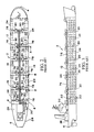
- tanker 2 includes a plurality of ballast tanks 24 arranged in both horizontal and vertical arrays between the tanker outer hull 8 and inner hull 10 .
- Each vertical array extends transverse to the longitudinal axis of tanker 10 along the side of the tanker and along the tanker bottom as illustrated in FIG. 4.
- Each horizontal array extends parallel to the longitudinal axis of tanker 10 as shown in FIG. 5.
- FIG. 4 shows that each off line 78 extends down a vertical array and into an array of ballast tanks along the side of the tanker 2 and along the tanker bottom 82 .
- a treatment line extends from each off line 78 into a horizontal array of tanks 24 .
- the treatment line extends into a horizontal array of three tanks 24 .
- a treatment line can extend into a horizontal array of any number of tanks.
- the tanks 24 are serially connected one after the other, to the ozone generator 30 by means of a treatment line and off line 78 via the feed line 74 .
- Each off line 78 includes consecutively connected treatment lines from a first treatment line to a final treatment line connected near the termination of the off line 78 near the keel 80 of the tanker 2 .
- Tanks 24 are serially connected to each consecutively connected off line 78 in a manner as aforesaid.
- a diffuser connects to a treatment line in each serially connected tank 24 .
- the diffuser is a duct, chamber or section in which a high-velocity, low-pressure stream of ozone is converted into a high-velocity high-pressure flow in the form of small uniform bubbles.
- a preferred diffuser is a rigid, monolithic, porous gas diffusion element formed of a body of solid particles and comprised of a partially coated, permeable ceramic substrate. The diffuser injects ozone into water within a ballast tank 24 in the form of diffuse, substantially uniform bubbles that form a continuous cascading treatment pattern.
- ozone is generated by ozone generator 30 and flows along the longitudinal axis of the tanker via main line 74 . If valve 80 is actuated to connect an off line to main line 74 , the ozone will be diffused into ballast water of the tank connected to the off line. The ozone diffusion is continued until the ballast water is substantially treated. During the treatment process, bromine and iodine is consumed in the destruction of the organisms. The bromine and iodine content of the water remains at a stable level until substantially all organisms have been destroyed. Then the bromine and iodine levels of the water begin to increase.
- FIGS. 1 to 3 There are a number of complexities that arise in adapting an ozone treatment process to the very large water volumes used in ballast tanks. Further complexities arise from requirements of uniform and substantial dispersal of the ozone into ballast water to achieve adequate biokill. While the FIGS. 1 to 3 system and method are generally effective, they require close, delicate control of both flow rate and time of ozone treatment to provide sufficient biokill. Additionally, the piping, valving and diffuser equipment required to service all the ballast tank water is substantial. The equipment is expensive and subject to failure.
- Equation (I) is an equilibrium reaction.
- the reaction is endothermic to produce O 3 , requiring energy, and is exothermic to produce O 2 , giving up energy.
- the actual efficiency of this ozone formation is relatively low, in the range of 2-8%, depending on the oxygen content of the feed gas and the temperature of the reaction.
- the oxygen-containing feed gas acquires a dilute mixture of ozone. This dilute mixture is then diffused through the treatment liquid.
- the high-energy state of ozone results in very low stability of the gas.
- ballast water that is loaded through a port of a sea faring vessel is injected with ozone prior to charging to a ballast tank.
- the invention can utilize a single point or a small number of ozone injection points prior to charge of the water to the ballast tank to eliminate many of the disadvantages of the prior art ballast tank diffuser method.
- ballast water that is discharged from a ballast tank is treated by injection of ozone into the unloading ballast water line prior to unloading to the sea.
- a rate of injection of the ozone into the water is adjusted and the rate of water loading into (or un-loading from) the vessel is adjusted to provide a target biokill of species within the water.
- a target biokill is determined, for example by consulting ballast water discharge regulations, and the rate of ozone injection into the water and/or the rate of water flow in the water line is adjusted to obtain the target biokill.
- the rate of injection can be adjusted and/or the rate of water loading can be adjusted to provide a concentration of ozone of 1.0 to 4.5 mg/l, desirably 1.5 to 4.0 mg/l and preferably 2.0 to 3.0 mg/l. This concentration can be effective to obtain in excess of 95% biokill of all species proscribed by the National Invasive Species Act.
- FIGS. 4 and 5 schematically represent a vessel 110 equipped with a loading water ozone injection system of the invention. Shown in the figures are the vessel “sea chest” stern section 112 with intake/discharge portal 114 .
- Water conduit 116 connects the intake/discharge port 114 with parallel longitudinal main header pipes 118 , 120 that traverse the vessel 110 from stern to a bow ballast tank connecting the intake/discharge port 114 with each of respective starboard and port batteries of ballast tanks 122 , 124 .
- Ballast water is loaded into the vessel 110 and is then pumped to load each ballast tank through the system of conduit and header pipes 116 , 118 and 120 shown.
- the process is reversed and water is pumped from each tank 122 , 124 through the conduit and header pipes 116 , 118 and 120 for discharge through intake/discharge port 114 to the sea.
- discharge can be effected through another, separate conduit and port system from the up-take and charge system.
- Ozone generator 126 is illustrated located on the aft deck 124 of the vessel 110 .
- the generator 126 can generate ozone as described by Rodden U.S. Pat. Nos. 6,125,778; 6,139,809; and 6,270,733. The disclosures of these patents are incorporated herein by reference in their entirety.
- the generated ozone is pumped through line 128 for injection into water in conduit 116 in accordance with this embodiment of the invention. After injection with ozone, the water is conveyed by one of the main header pipes 118 and 120 that run the entire length of the vessel 110 .
- a smaller footer pipe (not shown) can be taken off to provide a suction/discharge line. Valving for the footer pipe can be contained in a tunnel or cofferdam area, or actually placed in the tank itself, if space is an issue.
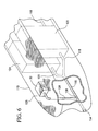
- FIGS. 6 to 9 illustrate embodiments of a system and method to inject ozone into water prior to loading the water into a ballast tank.
- like structures are identified with the same number.
- Each of the figures shows ozone generator 30 located on top deck 76 of a vessel 110 and each figure shows line 128 connecting the ozone generator 30 to a conduit 116 from intake/discharge port 114 .
- ozone is injected into ballast water in conduit 116 ; then conduit 116 divides into conduits 118 and 120 , each of which runs along the longitudinal axis of tanker 2 .
- FIG. 6 ozone generator 30 located on top deck 76 of a vessel 110 and each figure shows line 128 connecting the ozone generator 30 to a conduit 116 from intake/discharge port 114 .
- ozone is injected into ballast water in conduit 116 ; then conduit 116 divides into conduits 118 and 120 , each of which runs along the longitudinal axis of tanker 2 .
- conduit 118 delivers ozone treated water to each ballast tank of a starboard battery of tanks 122 and conduit 120 delivers ozone treated water to each ballast tank of a port battery of tanks 124 .
- Water enters through intake/discharge port 114 and is treated and charged into a tank of either the starboard battery or the port battery until each respective tank is sufficiently filled and balanced to compensate for off-loaded cargo.
- FIG. 7 shows line 128 to inject ozone into ballast water in conduit 116 .
- conduit 116 has a recycle conduit 130 that cycles a portion of the injected water from a position down stream from the point of ozone injection to a point upstream.
- the recycle provides enhance ozone injection to the ballast water.
- Valve 132 can control ozone injection into conduit 116 and valve 134 can control the proportion of recycle.
- the valves can be synchronized and tuned to control the degree of ozone treatment in the conduit 116 water.
- the conduit 116 Downstream from the recycle, as in FIG. 6, the conduit 116 divides into conduits 118 and 120 , each of which runs along the longitudinal axis of tanker 2 .
- conduit 118 delivers ozone treated water to each ballast tank of a starboard battery of tanks 122 and conduit 120 delivers ozone treated water to each ballast tank of a port battery of tanks 124 .
- FIG. 8 shows a system wherein ozone is injected into single points 136 , 138 , 140 in a plurality of conduits 142 , 144 and 146 , which can deliver ozone treated ballast water to a number of separately connected or serially connected ballast tanks. While FIG. 8 shows three conduits 142 , 144 and 146 , this depiction is intended to represent any number of a plurality of injection points prior to delivery of ozone to ballast tanks, or indeed, to represent any number of a plurality of injection points in conduits discharging ballast water from tanks.
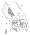
- FIG. 9 illustrates the concept of a loading tank 148 .
- ozone is injected into ballast water in conduit 116 ; then conduit 116 divides into conduits 118 and 120 , each of which runs along the longitudinal axis of tanker 2 .
- conduit 115 first fills loading tank 148 . Only after filling loading tank 148 is water allowed to flow into conduits 118 and 120 . After filling loading tank 148 , the flow is continuous into conduits 118 and 120 and is adjusted according to flow into the tank 148 to provide a steady state delivery to the tank and flow from the tank 148 . Residency time in tank 148 enlarges the opportunity to load ballast water with ozone for improved treatment and biokill.
- FIG. 9 shows a separate loading tank 142 .
- a first ballast tank can be used as a loading tank with overflow water from the first tank being conveyed to the other ballast tanks for filling one by one.
- FIG. 9 shows a like loading tank embodiment wherein ozone is charged directly into the tank 142 rather than into conduit 116 at a location upstream from the loading tank 142 .
- the invention advantageously minimizes system hardware particularly piping and control cabling.
- the invention replaces valves and controls from ballast tank water to extend system life and simplify maintenance and repair compared to an intank ballast water treatment system.
- FIG. 11 schematically illustrates a single point injection test system 150 .
- the system 150 can be used to determine effectiveness of a single point ozone injection treatment
- the FIG. 11 shows an ozone differential test module 152 with a sea water source 154 feeding through a 10 inch flexible hose 156 to a 11 ⁇ 2 inch main feed line 160 .
- the module 152 comprises a five gallon spike source 162 , centrifugal pump 164 with 40.0 CPM at 35 PSI capacity and a 3 ⁇ 4 inch return line 166 .
- a 3 ⁇ 4 inch flow line 168 comprising 1 to 1000 psi pressure gauge tubing connects an ozone generator 170 to the sea water main line 160 to divert incoming water for cooling purposes.
- a same gauge flow line 172 returns the sea water to main line 160 .
- Flow control value 174 is located on main feed line 160 downstream from centrifugal pump 164 .
- Flow meter 176 measures line flow at a location immediately down stream from the control valve 174 .
- a 1 ⁇ 4 inch Teflon tubing feed line 180 conveys ozone from generator 170 to a single point injection to main line 160 at point 182 .
- the single point 182 represents a location subsequent to sea water inflow into a vessel prior to charge into a vessel's ballast tanks.
- the experimental system 150 can represent a single point injection into ballast water as the water is expelled from ballast tanks to the sea as well.
- the feed line 180 includes centrifugal pump 182 with upstream gauge 184 and downstream gauge 186 , flow valve 188 and check valve 190 .
- Ozone generation and injection into incoming or discharging sea water in line 180 is controlled with the series of valves 188 , 190 and coordinated with flow control valve 174 and pump 164 to provide a target concentration of ozone (and correspondingly a targe biokill) within the water in line 160 .
- the injected water flows through inline static meter 192 and is then discharged into a battery of 75 gallon test tanks 194 each with a sampling port.
- Controller 196 controls water flow in line 196 via flow control valve 174 and ozone injection flow valve 188 and receives feed back on rate of injection and biokill from static meter 192 and sampling from the test tanks 194 .
- controller 196 controls 198 line 160 water flow in coordination with control 200 of ozone injection to effectively achieve biokill prior to water loading into ballast tanks represented by the tanks 194 or to effectively achieve biokill to discharging ballast water from ballast tanks to the sea.
- the system is operated until a target 95% biokill is obtained of species that are proscribed by the National Invasive Species Act. A concentration of 2.5 mg/l of ozone in the water is determined to provide target biokill.
Abstract
Description
- This application claims the benefit of U.S. Provisional Application Serial No. 60/372,806, filed Apr. 17, 2002, the disclosure of which is incorporated herein by reference in its entirety.
- The invention relates to a ballast water ozone injection method and system. More particularly, the invention relates to a system for using ozone to treat ballast water during loading or discharge of ballast water to or from the ballast tanks of a sea faring vessel.
- Ballast water weight is used by sea vessels to compensate for a lack of cargo weight when the cargo load is empty or partially empty. For example in a typical transport operation, a sea vessel docks at a first port where it is loaded with a cargo that the vessel transports to a second port where the cargo is unloaded. The vessel then returns to the first port where it is loaded with another cargo. Typically, the vessel travels empty from the second port back to the first port to pick up another cargo. The vessel is equipped with ballast tanks that can be filled with water to maintain the balance of the vessel on an even keel when it travels empty. Conventional ballast tanks include valves usually mounted over apertures through tank bulkheads. The valves are actuated to move water between and into and out of various ballast tanks to trim the vessel when empty of cargo or when carrying an unevenly distributed cargo.
- The vessel fills its ballast tanks by taking on sea water, usually at its cargo discharge port. The sea water is charged into the ballast tanks at the same time that the vessel off loads its cargo. The vessel then travels to its cargo loading port where it takes on cargo while at the same time it empties at least some and typically all of its ballast tanks by discharging the ballast water into the loading port water environment.
- The ballast water intake is below the water line of a vessel usually at or near the vessel hull bottom. The ballast water contains algae, zooplankton and other organisms that are indigenous to the cargo discharge port. Significant quantities of these indigenous organisms are loaded into the ballast tanks along with the water. The vessel then transports these organisms to the cargo loading port where the organisms are discharged into the water environment along with discharged ballast water. Some of these organisms may be deleterious to and very much unwanted in the loading port environment. They cause damage to the water environment and replace benthic organisms and clear plankton communities that provide food and larvae for resident native species in overlying waters.
- The zebra mussel (Dreissena polymorpha) is an example of an unwanted organism that has been spread by ballast water. The zebra mussel was first found in the mid eighteenth century in the northern Caspian Sea and in the Ural River. Since then, the mussel has spread to other parts of the world by means of ballast water discharge. The mussel was found in the Great Lakes in late 1988. It was first prevalent in Lake Erie. Since then, the mussel has spread into Lake Michigan and into rivers of the Midwest and Northeast.
- The mussel has threadlike tentacles that enable it to adhere to any vertical or horizontal surface. It is particularly adherent to the shell of another mussel. It reproduces quickly and in a brief time can obtain population densities in excess of 30,000 mussels per square meter. Stacks of adhering mussels have been known to completely clog water intake orifices and shut down municipal water treatment plants and industrial water systems.
- In 1996, Congress passed the National Invasive Species Act (P. L. 104-332) to stem the spread of nonindigenous organisms by ballast water discharge. The act reauthorized the Great Lakes ballast management program and expanded applicability to vessels with ballast tanks. The Act requires the Secretary of Transportation to develop national guidelines to prevent the spread of organisms and their introduction into U.S. waters via ballast water of commercial vessels.
- Guidelines developed pursuant to the can require vessels that enter U.S. waters to undertake ballast exchange in the high seas. Ballast water exchange involves replacing coastal water with open-ocean water during a voyage. This process reduces the density of coastal organisms by replacing them with oceanic organisms with a lower probability of survival in near shore waters. However, ballast exchange has two important short-comings. First, the ability to safely conduct ballast water exchange depends upon weather and sea surface conditions, and it is not always possible to perform an exchange. Second, there is still some residual density of coastal organisms in ballast tanks following exchange, so the process is only partly effective.
- There is a need for a safe and effective method and system to treat ballast water for discharge into destination water environments.
- The invention relates to a safe and effective method and system to treat ballast water. The method comprises injecting ozone into water loading into a sea faring vessel prior to charging the water into a ballast tank; and charging the ozone injected water into the ballast tank. The system comprises a sea faring vessel including at least one ballast tank; an ozone generator that generates ozone, a ballast water conduit that uptakes water through a loading port of the sea faring vessel and conducts the water to load the ballast tank; and an ozone feed line that injects ozone from the generator into water in the conduit at an injection point located upstream to an intersection of the conduit with the ballast tank.
- In an embodiment, the method of treating ballast water comprises pumping ballast water into a sea faring vessel through a flow line; and injecting ozone into the ballast water as it flows through the flow line.
- Another method of ozone treatment comprises injecting ozone into water discharging from a ballast tank at a location downstream from the tank; and unloading the ozone injected water to the sea.
- In another embodiment, a ballast-water treatment system comprises a sea faring vessel including at least one ballast tank; an ozone generator that generates ozone, a ballast water conduit that discharges water from the ballast tank and conducts the water to an unloading port of the sea faring vessel; and an ozone feed line that injects ozone from the generator into water in the conduit at an injection point located downstream to an intersection of the conduit with the ballast tank.
- FIG. 1 is a schematic perspective view of a double hulled tanker and a prior art ballast water treatment system;
- FIG. 2 is a schematic top view of a prior art tanker and treatment system;
- FIG. 3 is a schematic side view of a prior art tanker and treatment system;
- FIG. 4 is a schematic top view of a tanker and treatment system illustrating an embodiment of the invention;
- FIG. 5 is a schematic side view of the tanker of FIG. 4;
- FIGS. 6 to 10 are schematic representations of embodiments of ballast water ozone injection methods and systems; and
- FIG. 11 is a schematic representation of a system to conduct a test ballast water ozone injection.
- Ozone (O 3) is an allotropic form of oxygen. It is an unstable blue gas with a pungent odor, a molecular weight of 48 g/mol and a density as a gas of 2.154 g/liter at 0° and 1 atm. It is approximately 13 times more soluble in water than is oxygen. Ozone is highly unstable and is a powerful oxidizing agent. It is 1.5 times better and approximately 3125 times faster than chlorine as an oxidizer. It is non-persistent and has a very short half-life. Its half-life in pure distilled water is approximately 40 min at pH 7.6. Because of the unstable nature of the O3 molecule, it cannot be stored but must be generated on-site.
- Typically, ozone is produced by passing oxygen, in some concentration, through a highly charged corona field, a technique known as “corona discharge”. The corona may be produced by applying a very high electric potential (20 kV) between two conductors that are separated by an insulating dielectric layer and a small air gap. Under these conditions, molecular oxygen (O 2) passing through the gap between the conductors experiences sufficient dissociation energy to partially ionize. A certain fraction of the free oxygen ions will re-associate in the form of O3, according to the equilibrium reaction equation:
- 3O2+69 kcal⇄2O3 (I)
- Ozone is currently used as a means for purifying liquids, but most applications for this technology have centered on relatively low liquid volume applications. Ozone has been increasingly suggested as a candidate for very large scale liquid purification projects. For example, ozone has been used to treat ballast water in ballast water tanks. The ozone rapidly converts naturally occurring ballast water iodides and bromides into bromine and iodine, which can be toxic to organisms. The general concept of ballast water treatment with ozone is to use a sea faring vessel's transit time between ports as an opportunity for treatment. In-transit ozone treatment of ballast water has been found to be cost-effective and environmentally sound. Ozone treatment is viewed as superior to both chemical treatment, which may require the transportation and disposal of hazardous substances over the sea, and separation technology, which is uneconomical because of the large volume of water requiring treatment.
- Commonly assigned Rodden, U.S. Pat. No. 6,125,778 teaches a method to render ballast water free of contaminating organisms. In the Rodden method, a ballast water treatment system includes a source of ozone and a ballast tank connected to the source of ozone. The ozone is provided to a ballast tank through an ozone-transport system. The system may include a pressure generation system to regulate a flow pressure such that the flow pressure is substantially ambient at an exit end of the ozone generator while the ozone is injected under a positive pressure when reaching the ballast tank.
- The Rodden system and method are illustrated in FIGS. 1 to 3, wherein
tanker 2 includes bow 4,stem 6 and a double hull formed fromouter hull 8 andinner hull 10.Tanker 2 can be a very large carrier designed for transporting crude oil. However, the present invention can be applied to any sea faring ship or vessel that has ballast tanks or bilge water.Tanker 2 is representative of the types of vessels encompassed within the invention and is a conventionally proportioned double hulled oil tanker having cargo compartments withininner hull 10. Thetanker 2 is typical of vessels that transport partly or fully refined or residual petroleum or other bulk liquid products such as seed oil. -
Tank section 12 oftanker 2 is formed by the interior surface ofinner hull 10 and includes aport tank section 14 and astarboard tank section 16, which are separated by longitudinal bulkhead 18. The longitudinal bulkhead 18 extends the length oftank section 12. Theport tank section 14 andstarboard tank section 16 are divided along their lengths bytransverse bulkheads 20. Thetransverse bulkheads 20 extend into the spacing betweenouter hull 8 andinner hull 10. The spacing is also divided by plating 22, which together withtransverse bulkheads 20 divide the double hull spacing into a plurality ofballast tanks 24. - The
ballast tanks 24 are filled or partially filled with water to maintain the balance of thetanker 2 on an even keel, particularly when it travels empty or partially filled.Tanker 2 typically fills itsballast tanks 24 by taking on water at its cargo discharge port. This water contains species indigenous to the discharge port. As described aforesaid, these species may be harmful to the environment at a cargo loading port where ballast water is discharged to balance added weight of loaded cargo. Thetanker 2 may exchange the ballast water in open sea to avoid discharge at the loading port. However, this is a dangerous and labor intensive procedure. According to the present invention, ballast water is treated with ozone while thetanker 2 is in transit between ports to destroy the harmful species. Then, the treated ballast water can be discharged at a loading port without introducing foreign species into the loading port environment. - The Rodden patent describes an in transit ozone treatment of ballast water by means of a treatment system shown in FIGS. 1 to 3. The system includes a source of ozone that can be located anywhere on a vessel with ballast water in need of treatment. In FIGS. 1 to 3, an
ozone generator 30 is located onbridge 26 ofaft section 28.Ozone generator 30 can be any apparatus for the generation of ozone. Theozone generator 30 can include a tubular generator or a battery of tubular ozone generators. - Main
ozone feed line 74 runs fromozone generator 30 alongtop deck 76 parallel to the longitudinal axis oftanker 10. Offlines 78 intersectfeed line 74 at 90 degree angles and connect to feedline 74 viavalves 80. Each offline 74 runs from arespective valve 80 transverse to thefeed line 74 and to the longitudinal axis oftanker 10, thence downwardly throughtop deck 76 into aballast tank 24. As shown in FIGS. 3 to 5,tanker 2 includes a plurality ofballast tanks 24 arranged in both horizontal and vertical arrays between the tankerouter hull 8 andinner hull 10. Each vertical array extends transverse to the longitudinal axis oftanker 10 along the side of the tanker and along the tanker bottom as illustrated in FIG. 4. Each horizontal array extends parallel to the longitudinal axis oftanker 10 as shown in FIG. 5. FIG. 4 shows that each offline 78 extends down a vertical array and into an array of ballast tanks along the side of thetanker 2 and along the tanker bottom 82. A treatment line extends from each offline 78 into a horizontal array oftanks 24. The treatment line extends into a horizontal array of threetanks 24. However, a treatment line can extend into a horizontal array of any number of tanks. Thetanks 24 are serially connected one after the other, to theozone generator 30 by means of a treatment line and offline 78 via thefeed line 74. Each offline 78 includes consecutively connected treatment lines from a first treatment line to a final treatment line connected near the termination of theoff line 78 near thekeel 80 of thetanker 2.Tanks 24 are serially connected to each consecutively connected offline 78 in a manner as aforesaid. - A diffuser connects to a treatment line in each serially connected
tank 24. The diffuser is a duct, chamber or section in which a high-velocity, low-pressure stream of ozone is converted into a high-velocity high-pressure flow in the form of small uniform bubbles. A preferred diffuser is a rigid, monolithic, porous gas diffusion element formed of a body of solid particles and comprised of a partially coated, permeable ceramic substrate. The diffuser injects ozone into water within aballast tank 24 in the form of diffuse, substantially uniform bubbles that form a continuous cascading treatment pattern. - In operation, ozone is generated by
ozone generator 30 and flows along the longitudinal axis of the tanker viamain line 74. Ifvalve 80 is actuated to connect an off line tomain line 74, the ozone will be diffused into ballast water of the tank connected to the off line. The ozone diffusion is continued until the ballast water is substantially treated. During the treatment process, bromine and iodine is consumed in the destruction of the organisms. The bromine and iodine content of the water remains at a stable level until substantially all organisms have been destroyed. Then the bromine and iodine levels of the water begin to increase. Hence, effectiveness of ozone treatment of ballast water within a tank can be monitored by monitoring the ballast water bromine and/or iodine content. Periodic sampling of the water can be conducted. When the bromine and/or iodine content commences to increase to residual levels of about 1 ppm to about 2 ppm or greater then biokill of organisms is assured and ozone treatment can be can be terminated. - There are a number of complexities that arise in adapting an ozone treatment process to the very large water volumes used in ballast tanks. Further complexities arise from requirements of uniform and substantial dispersal of the ozone into ballast water to achieve adequate biokill. While the FIGS. 1 to 3 system and method are generally effective, they require close, delicate control of both flow rate and time of ozone treatment to provide sufficient biokill. Additionally, the piping, valving and diffuser equipment required to service all the ballast tank water is substantial. The equipment is expensive and subject to failure.
- Another problem with the equipment intensive method and system of FIGS. 1 to 3 is engendered by the chemistry of the ozone generation reaction. Equation (I) is an equilibrium reaction. The reaction is endothermic to produce O3, requiring energy, and is exothermic to produce O2, giving up energy. Because of its equilibrium nature, the actual efficiency of this ozone formation is relatively low, in the range of 2-8%, depending on the oxygen content of the feed gas and the temperature of the reaction. After being processed in this way, the oxygen-containing feed gas acquires a dilute mixture of ozone. This dilute mixture is then diffused through the treatment liquid. However, the high-energy state of ozone results in very low stability of the gas. The natural tendency is for the ozone to revert back to the more stable, lower-energy allotrope O2. While the solubility of ozone in water is approximately 13 times as great as the solubility of O2, it has a very short half-life, about 40 minutes in distilled water at a pH of 7.6. Consequently, the storage of ozone is impractical and ozone generation must be performed substantially at the location of use.
- In accordance with the invention, ballast water that is loaded through a port of a sea faring vessel is injected with ozone prior to charging to a ballast tank. The invention can utilize a single point or a small number of ozone injection points prior to charge of the water to the ballast tank to eliminate many of the disadvantages of the prior art ballast tank diffuser method. In another embodiment, ballast water that is discharged from a ballast tank is treated by injection of ozone into the unloading ballast water line prior to unloading to the sea. Surprisingly, despite the short half-life of ozone and the difficulty of charging a flow of water, injection of ozone to loading or discharging ballast water provides a residence time and diffusion for satisfactorily biokill. In an embodiment of the invention, a rate of injection of the ozone into the water is adjusted and the rate of water loading into (or un-loading from) the vessel is adjusted to provide a target biokill of species within the water. In this process, a target biokill is determined, for example by consulting ballast water discharge regulations, and the rate of ozone injection into the water and/or the rate of water flow in the water line is adjusted to obtain the target biokill. For example, the rate of injection can be adjusted and/or the rate of water loading can be adjusted to provide a concentration of ozone of 1.0 to 4.5 mg/l, desirably 1.5 to 4.0 mg/l and preferably 2.0 to 3.0 mg/l. This concentration can be effective to obtain in excess of 95% biokill of all species proscribed by the National Invasive Species Act.
- Features of the invention will become apparent from the drawings and following detailed discussion, which by way of example without limitation describe preferred embodiments of the invention.
- FIGS. 4 and 5 schematically represent a
vessel 110 equipped with a loading water ozone injection system of the invention. Shown in the figures are the vessel “sea chest”stern section 112 with intake/discharge portal 114.Water conduit 116 connects the intake/discharge port 114 with parallel longitudinalmain header pipes vessel 110 from stern to a bow ballast tank connecting the intake/discharge port 114 with each of respective starboard and port batteries ofballast tanks vessel 110 and is then pumped to load each ballast tank through the system of conduit andheader pipes tank header pipes discharge port 114 to the sea. Or, discharge can be effected through another, separate conduit and port system from the up-take and charge system. -
Ozone generator 126 is illustrated located on theaft deck 124 of thevessel 110. The generator126 can generate ozone as described by Rodden U.S. Pat. Nos. 6,125,778; 6,139,809; and 6,270,733. The disclosures of these patents are incorporated herein by reference in their entirety. The generated ozone is pumped throughline 128 for injection into water inconduit 116 in accordance with this embodiment of the invention. After injection with ozone, the water is conveyed by one of themain header pipes vessel 110. As aheader pipe ballast tank - FIGS. 6 to 9 illustrate embodiments of a system and method to inject ozone into water prior to loading the water into a ballast tank. In each of FIGS. 6 to 9, like structures are identified with the same number. Each of the figures shows
ozone generator 30 located ontop deck 76 of avessel 110 and each figure showsline 128 connecting theozone generator 30 to aconduit 116 from intake/discharge port 114. In FIG. 6 ozone is injected into ballast water inconduit 116; thenconduit 116 divides intoconduits tanker 2. In FIG. 6,conduit 118 delivers ozone treated water to each ballast tank of a starboard battery oftanks 122 andconduit 120 delivers ozone treated water to each ballast tank of a port battery oftanks 124. Water enters through intake/discharge port 114 and is treated and charged into a tank of either the starboard battery or the port battery until each respective tank is sufficiently filled and balanced to compensate for off-loaded cargo. - FIG. 7 shows
line 128 to inject ozone into ballast water inconduit 116. In this embodiment,conduit 116 has arecycle conduit 130 that cycles a portion of the injected water from a position down stream from the point of ozone injection to a point upstream. The recycle provides enhance ozone injection to the ballast water.Valve 132 can control ozone injection intoconduit 116 andvalve 134 can control the proportion of recycle. The valves can be synchronized and tuned to control the degree of ozone treatment in theconduit 116 water. Downstream from the recycle, as in FIG. 6, theconduit 116 divides intoconduits tanker 2. As in FIG. 6,conduit 118 delivers ozone treated water to each ballast tank of a starboard battery oftanks 122 andconduit 120 delivers ozone treated water to each ballast tank of a port battery oftanks 124. - FIG. 8 shows a system wherein ozone is injected into
single points conduits 142, 144 and 146, which can deliver ozone treated ballast water to a number of separately connected or serially connected ballast tanks. While FIG. 8 shows threeconduits 142, 144 and 146, this depiction is intended to represent any number of a plurality of injection points prior to delivery of ozone to ballast tanks, or indeed, to represent any number of a plurality of injection points in conduits discharging ballast water from tanks. - FIG. 9 illustrates the concept of a loading tank 148. In this embodiment, ozone is injected into ballast water in
conduit 116; thenconduit 116 divides intoconduits tanker 2. However, in this embodiment, conduit 115 first fills loading tank 148. Only after filling loading tank 148 is water allowed to flow intoconduits conduits separate loading tank 142. However, in actuality a first ballast tank can be used as a loading tank with overflow water from the first tank being conveyed to the other ballast tanks for filling one by one. FIG. 9 shows a like loading tank embodiment wherein ozone is charged directly into thetank 142 rather than intoconduit 116 at a location upstream from theloading tank 142. - The invention advantageously minimizes system hardware particularly piping and control cabling. The invention replaces valves and controls from ballast tank water to extend system life and simplify maintenance and repair compared to an intank ballast water treatment system.
- The following EXAMPLE is illustrative and should not be construed as a limitation on the scope of the claims unless a limitation is specifically recited.
- FIG. 11 schematically illustrates a single point
injection test system 150. Thesystem 150 can be used to determine effectiveness of a single point ozone injection treatment , The FIG. 11 shows an ozonedifferential test module 152 with asea water source 154 feeding through a 10 inchflexible hose 156 to a 1½ inchmain feed line 160. Themodule 152 comprises a fivegallon spike source 162,centrifugal pump 164 with 40.0 CPM at 35 PSI capacity and a ¾inch return line 166. A ¾inch flow line 168 comprising 1 to 1000 psi pressure gauge tubing connects anozone generator 170 to the sea watermain line 160 to divert incoming water for cooling purposes. A samegauge flow line 172 returns the sea water tomain line 160.Flow control value 174 is located onmain feed line 160 downstream fromcentrifugal pump 164.Flow meter 176 measures line flow at a location immediately down stream from thecontrol valve 174. - A ¼ inch Teflon
tubing feed line 180 conveys ozone fromgenerator 170 to a single point injection tomain line 160 atpoint 182. Thesingle point 182 represents a location subsequent to sea water inflow into a vessel prior to charge into a vessel's ballast tanks. However, it should be understood that theexperimental system 150 can represent a single point injection into ballast water as the water is expelled from ballast tanks to the sea as well. In thetest system 150, thefeed line 180 includescentrifugal pump 182 withupstream gauge 184 anddownstream gauge 186,flow valve 188 andcheck valve 190. Ozone generation and injection into incoming or discharging sea water inline 180 is controlled with the series ofvalves flow control valve 174 and pump 164 to provide a target concentration of ozone (and correspondingly a targe biokill) within the water inline 160. The injected water flows through inlinestatic meter 192 and is then discharged into a battery of 75gallon test tanks 194 each with a sampling port.Controller 196 controls water flow inline 196 viaflow control valve 174 and ozoneinjection flow valve 188 and receives feed back on rate of injection and biokill fromstatic meter 192 and sampling from thetest tanks 194. In operation,controller 196controls 198line 160 water flow in coordination withcontrol 200 of ozone injection to effectively achieve biokill prior to water loading into ballast tanks represented by thetanks 194 or to effectively achieve biokill to discharging ballast water from ballast tanks to the sea. The system is operated until a target 95% biokill is obtained of species that are proscribed by the National Invasive Species Act. A concentration of 2.5 mg/l of ozone in the water is determined to provide target biokill. - While preferred embodiments of the invention have been described, the present invention is capable of variation and modification and therefore should not be limited to the precise details of the Examples. The invention includes changes and alterations that fall within the purview of the following claims.
Claims (46)
Priority Applications (6)
| Application Number | Priority Date | Filing Date | Title |
|---|---|---|---|
| US10/402,298 US6869540B2 (en) | 2002-04-17 | 2003-03-31 | Ballast water ozone injection method and system |
| US11/039,819 US7273562B2 (en) | 2002-04-17 | 2005-01-24 | Ozone injection method and system |
| US11/226,358 US7416660B2 (en) | 2002-04-17 | 2005-09-15 | Bypass flow and ozone proportion method and system |
| US11/226,359 US7402253B2 (en) | 2002-04-17 | 2005-09-15 | Controlled bypass flow and ozone proportion method and system |
| US11/230,571 US7407592B2 (en) | 2002-04-17 | 2005-09-21 | Ozone retention method and system |
| US11/246,235 US7381338B2 (en) | 2002-04-17 | 2005-10-11 | Ballast water treatment system and method without off-gas |
Applications Claiming Priority (2)
| Application Number | Priority Date | Filing Date | Title |
|---|---|---|---|
| US37280602P | 2002-04-17 | 2002-04-17 | |
| US10/402,298 US6869540B2 (en) | 2002-04-17 | 2003-03-31 | Ballast water ozone injection method and system |
Related Child Applications (1)
| Application Number | Title | Priority Date | Filing Date |
|---|---|---|---|
| US11/039,819 Continuation-In-Part US7273562B2 (en) | 2002-04-17 | 2005-01-24 | Ozone injection method and system |
Publications (2)
| Publication Number | Publication Date |
|---|---|
| US20030196967A1 true US20030196967A1 (en) | 2003-10-23 |
| US6869540B2 US6869540B2 (en) | 2005-03-22 |
Family
ID=29218898
Family Applications (1)
| Application Number | Title | Priority Date | Filing Date |
|---|---|---|---|
| US10/402,298 Expired - Lifetime US6869540B2 (en) | 2002-04-17 | 2003-03-31 | Ballast water ozone injection method and system |
Country Status (1)
| Country | Link |
|---|---|
| US (1) | US6869540B2 (en) |
Cited By (20)
| Publication number | Priority date | Publication date | Assignee | Title |
|---|---|---|---|---|
| US20040251215A1 (en) * | 2003-06-13 | 2004-12-16 | Mindong Bai | Method for killing organicsms in the course of conveying ballast water in ships and apparatus thereof |
| US20080000775A1 (en) * | 2005-01-18 | 2008-01-03 | Childers Harold E Ii | System and Process for Treating Ballast Water |
| US20080017586A1 (en) * | 2006-02-15 | 2008-01-24 | Matousek Rudolf C | Ballast tank circulation management system |
| US20080149485A1 (en) * | 2005-01-18 | 2008-06-26 | Childers Harold E | System and Process for Treatment and De-halogenation of Ballast Water |
| US20100006490A1 (en) * | 2006-09-29 | 2010-01-14 | Yasuwo Fukuyo | Treatment Apparatus for Ship Ballast Water |
| WO2010046906A2 (en) * | 2008-09-16 | 2010-04-29 | Mehta Virendra J | Method and system for managing ballast water |
| US20100181260A1 (en) * | 2005-10-28 | 2010-07-22 | Resource Ballast Technologies (Proprietary) Limited | Method and Apparatus for Water Treatment to Eliminate Aquatic Organisms |
| US8147686B2 (en) * | 2007-07-31 | 2012-04-03 | Mitsui Engineering & Shipbuilding Co., Ltd | Ballast water treatment apparatus |
| US8701014B1 (en) | 2002-11-18 | 2014-04-15 | Facebook, Inc. | Account linking |
| US8775560B2 (en) | 2002-11-18 | 2014-07-08 | Facebook, Inc. | Host-based intelligent results related to a character stream |
| US20150232357A1 (en) * | 2013-12-27 | 2015-08-20 | Clean Liquid, Llc | Real-time system and processes for controlling ozone gas |
| US9203879B2 (en) | 2000-03-17 | 2015-12-01 | Facebook, Inc. | Offline alerts mechanism |
| US9253136B2 (en) | 2002-11-18 | 2016-02-02 | Facebook, Inc. | Electronic message delivery based on presence information |
| US9313046B2 (en) | 2002-11-18 | 2016-04-12 | Facebook, Inc. | Presenting dynamic location of a user |
| US9319356B2 (en) | 2002-11-18 | 2016-04-19 | Facebook, Inc. | Message delivery control settings |
| US9516125B2 (en) | 2003-03-26 | 2016-12-06 | Facebook, Inc. | Identifying and using identities deemed to be known to a user |
| US9774560B2 (en) | 2002-11-18 | 2017-09-26 | Facebook, Inc. | People lists |
| US20170349051A1 (en) * | 2016-06-06 | 2017-12-07 | Edward Connell | System and Method for Recharging Power Storage Devices on a Watercraft |
| US10187334B2 (en) | 2003-11-26 | 2019-01-22 | Facebook, Inc. | User-defined electronic message preferences |
| ES2881849A1 (en) * | 2020-05-27 | 2021-11-30 | Gonzalez Batanero Diego | Equipment for the disinfection and inerting of biological species for its application in cleaning floating and fixed structures in aquatic environments, ships, polishing propellers, ballast tanks, and water filtering systems. (Machine-translation by Google Translate, not legally binding) |
Families Citing this family (22)
| Publication number | Priority date | Publication date | Assignee | Title |
|---|---|---|---|---|
| WO2003093176A2 (en) | 2002-05-02 | 2003-11-13 | Peter Drummond Mcnulty | Apparatus and method for water treatment |
| US6984330B2 (en) * | 2003-07-07 | 2006-01-10 | Mote Marine Laboratory | Use of ozone for controlling growth of organisms |
| WO2005076771A2 (en) * | 2003-07-18 | 2005-08-25 | Environmental Technologies, Inc. | On-board water treatment and management process and apparatus |
| WO2005122054A2 (en) * | 2004-01-22 | 2005-12-22 | The Glosten Associates, Inc. | Apparatus and method of vessel emission management |
| JP4964120B2 (en) | 2005-01-24 | 2012-06-27 | ニューテック オースリー インコーポレイテッド | Method and system for injecting ozone |
| US9010261B2 (en) | 2010-02-11 | 2015-04-21 | Allen Szydlowski | Method and system for a towed vessel suitable for transporting liquids |
| US8007845B2 (en) | 2005-10-21 | 2011-08-30 | Waters of Patagonia | Method and system for recovering and preparing glacial water |
| US8403718B2 (en) | 2010-02-11 | 2013-03-26 | Allen Szydlowski | Method and system for a towed vessel suitable for transporting liquids |
| US9521858B2 (en) | 2005-10-21 | 2016-12-20 | Allen Szydlowski | Method and system for recovering and preparing glacial water |
| US8496808B2 (en) * | 2007-03-16 | 2013-07-30 | Seair Inc | Wastewater treatment apparatus |
| US7900780B2 (en) * | 2007-08-16 | 2011-03-08 | Mitsui Engineering & Shipbuilding Co., Ltd. | Ballast water intake and treatment system |
| CA2653493C (en) * | 2008-01-16 | 2015-03-24 | Seair Inc. | Flow through water treatment apparatus |
| US9017123B2 (en) | 2009-10-15 | 2015-04-28 | Allen Szydlowski | Method and system for a towed vessel suitable for transporting liquids |
| US20110091607A1 (en) * | 2009-10-15 | 2011-04-21 | Allen Szydlowski | Method and system for processing glacial water |
| US9371114B2 (en) | 2009-10-15 | 2016-06-21 | Allen Szydlowski | Method and system for a towed vessel suitable for transporting liquids |
| WO2011047275A1 (en) | 2009-10-15 | 2011-04-21 | World's Fresh Waters Pte. Ltd | Method and system for processing glacial water |
| US11584483B2 (en) | 2010-02-11 | 2023-02-21 | Allen Szydlowski | System for a very large bag (VLB) for transporting liquids powered by solar arrays |
| CA2712046C (en) | 2010-08-12 | 2015-10-20 | Harold Kinasewich | Headspace gas treatment apparatus and method |
| CA3202964A1 (en) | 2011-12-06 | 2013-06-13 | Delta Faucet Company | Ozone distribution in a faucet |
| UA115322C2 (en) | 2012-01-31 | 2017-10-25 | Сіейр Інк. | Multi-stage aeration apparatus |
| US9132892B2 (en) * | 2013-12-06 | 2015-09-15 | Gva Consultants Ab | Floating vessel with tunnel |
| CN108463437B (en) | 2015-12-21 | 2022-07-08 | 德尔塔阀门公司 | Fluid delivery system comprising a disinfection device |
Citations (30)
| Publication number | Priority date | Publication date | Assignee | Title |
|---|---|---|---|---|
| US88758A (en) * | 1869-04-06 | Improvement in cultivators | ||
| US162803A (en) * | 1875-05-04 | Improvement in bottle-stoppers | ||
| US191483A (en) * | 1877-05-29 | Improvement in dumping-wagons | ||
| US3937662A (en) * | 1974-05-13 | 1976-02-10 | Keene Corporation | Marine discharge control apparatus and method for treating fluids on a marine vessel |
| US4314519A (en) * | 1979-03-13 | 1982-02-09 | Yamashita-Shinnihon Steamship Co., Ltd. | Ballast pumping system |
| US4317333A (en) * | 1978-07-25 | 1982-03-02 | Webby Charles W | Remote water cooled heat engine |
| US4364516A (en) * | 1980-01-17 | 1982-12-21 | Chem-Lawn Corporation | Injector |
| US4619763A (en) * | 1983-07-21 | 1986-10-28 | Brien Edward J O | Ozone H2 O treatment |
| US5040487A (en) * | 1990-05-03 | 1991-08-20 | Bollyky Associates, Inc. | Method for controlling Zebra Mussel (Dreissena polymorpha) |
| US5218988A (en) * | 1991-09-25 | 1993-06-15 | Beta Technology, Inc. | Liquid feed system |
| US5494576A (en) * | 1992-06-15 | 1996-02-27 | Pollution Management Industries | System and method for treating water |
| US5785067A (en) * | 1996-10-15 | 1998-07-28 | Ez Environmental Solutions Corporation | Pressure washing apparatus with ozonation |
| US5803982A (en) * | 1996-10-15 | 1998-09-08 | Ez Environmental Solutions Corporation | Pressure washing apparatus with ozone generator |
| US5816181A (en) * | 1996-02-14 | 1998-10-06 | Sherman, Jr.; Thomas W. | Ballast water treatment system |
| US5932112A (en) * | 1996-11-27 | 1999-08-03 | Browning Transport Management, Inc. | Method and apparatus for killing microorganisms in ship ballast water |
| US6000418A (en) * | 1997-03-20 | 1999-12-14 | International Business Machines Corporation | Integrated dynamic fluid mixing apparatus and method |
| US6053121A (en) * | 1997-07-08 | 2000-04-25 | Teekay Shipping Corporation | Method and apparatus for exchanging ballast water in a ship |
| US6106731A (en) * | 1998-10-05 | 2000-08-22 | Hayes; Charles R. | System and method for ozonating water for animal houses |
| US6125778A (en) * | 1998-03-16 | 2000-10-03 | Rodden; Raymond M. | Ballast water treatment |
| US6165371A (en) * | 1996-03-12 | 2000-12-26 | Allen; John Leon | Off-shore sewage treating and handling apparatus and method |
| US6205981B1 (en) * | 1999-03-24 | 2001-03-27 | Siemens Automotive Corporation | Fuel recirculation for direct injection fuel system using a high pressure variable venturi pump |
| US6231769B1 (en) * | 1997-06-17 | 2001-05-15 | L'air Liquide, Societe Anonyme Pour L'etude Et L'exploitation Des Procedes Georges Claude | Installation for producing ozonized water |
| US6402965B1 (en) * | 1999-07-13 | 2002-06-11 | Oceanit Laboratories, Inc. | Ship ballast water ultrasonic treatment |
| US6432304B1 (en) * | 2001-04-18 | 2002-08-13 | Hap Nguyen | Remote operating ballast filter for vessels |
| US6500345B2 (en) * | 2000-07-31 | 2002-12-31 | Maritime Solutions, Inc. | Apparatus and method for treating water |
| US20030015481A1 (en) * | 2001-06-28 | 2003-01-23 | Eidem Ola Magne | Method and apparatus for treating/disinfecting ballast water in ships |
| US6516738B2 (en) * | 2000-12-01 | 2003-02-11 | Nutech O3 | Method and apparatus for delivering ozone to ballast tanks |
| US6613232B2 (en) * | 2000-03-21 | 2003-09-02 | Warren Howard Chesner | Mobile floating water treatment vessel |
| US20040055966A1 (en) * | 2002-06-29 | 2004-03-25 | Hap Nguyen | Ballast water treatment systems including related apparatus and methods |
| US20040060876A1 (en) * | 2002-09-30 | 2004-04-01 | Tipton Gary A. | Bilge water reclamation system and process |
Family Cites Families (4)
| Publication number | Priority date | Publication date | Assignee | Title |
|---|---|---|---|---|
| US6217770B1 (en) | 1998-08-14 | 2001-04-17 | Atp International | Apparatus and method for treatment of water |
| CA2246711A1 (en) * | 1998-10-02 | 2000-04-02 | Betzdearborn Inc. | Methods for controlling macroinvertebrates in aqueous systems |
| US6919031B2 (en) | 2000-11-02 | 2005-07-19 | I. Kruger Inc. | Method of treating water and wastewater with a ballasted flocculation process and a chemical precipitation process |
| JP2002306938A (en) | 2001-04-11 | 2002-10-22 | Horiba Ltd | Fluid mixer |
-
2003
- 2003-03-31 US US10/402,298 patent/US6869540B2/en not_active Expired - Lifetime
Patent Citations (30)
| Publication number | Priority date | Publication date | Assignee | Title |
|---|---|---|---|---|
| US88758A (en) * | 1869-04-06 | Improvement in cultivators | ||
| US162803A (en) * | 1875-05-04 | Improvement in bottle-stoppers | ||
| US191483A (en) * | 1877-05-29 | Improvement in dumping-wagons | ||
| US3937662A (en) * | 1974-05-13 | 1976-02-10 | Keene Corporation | Marine discharge control apparatus and method for treating fluids on a marine vessel |
| US4317333A (en) * | 1978-07-25 | 1982-03-02 | Webby Charles W | Remote water cooled heat engine |
| US4314519A (en) * | 1979-03-13 | 1982-02-09 | Yamashita-Shinnihon Steamship Co., Ltd. | Ballast pumping system |
| US4364516A (en) * | 1980-01-17 | 1982-12-21 | Chem-Lawn Corporation | Injector |
| US4619763A (en) * | 1983-07-21 | 1986-10-28 | Brien Edward J O | Ozone H2 O treatment |
| US5040487A (en) * | 1990-05-03 | 1991-08-20 | Bollyky Associates, Inc. | Method for controlling Zebra Mussel (Dreissena polymorpha) |
| US5218988A (en) * | 1991-09-25 | 1993-06-15 | Beta Technology, Inc. | Liquid feed system |
| US5494576A (en) * | 1992-06-15 | 1996-02-27 | Pollution Management Industries | System and method for treating water |
| US5816181A (en) * | 1996-02-14 | 1998-10-06 | Sherman, Jr.; Thomas W. | Ballast water treatment system |
| US6165371A (en) * | 1996-03-12 | 2000-12-26 | Allen; John Leon | Off-shore sewage treating and handling apparatus and method |
| US5785067A (en) * | 1996-10-15 | 1998-07-28 | Ez Environmental Solutions Corporation | Pressure washing apparatus with ozonation |
| US5803982A (en) * | 1996-10-15 | 1998-09-08 | Ez Environmental Solutions Corporation | Pressure washing apparatus with ozone generator |
| US5932112A (en) * | 1996-11-27 | 1999-08-03 | Browning Transport Management, Inc. | Method and apparatus for killing microorganisms in ship ballast water |
| US6000418A (en) * | 1997-03-20 | 1999-12-14 | International Business Machines Corporation | Integrated dynamic fluid mixing apparatus and method |
| US6231769B1 (en) * | 1997-06-17 | 2001-05-15 | L'air Liquide, Societe Anonyme Pour L'etude Et L'exploitation Des Procedes Georges Claude | Installation for producing ozonized water |
| US6053121A (en) * | 1997-07-08 | 2000-04-25 | Teekay Shipping Corporation | Method and apparatus for exchanging ballast water in a ship |
| US6125778A (en) * | 1998-03-16 | 2000-10-03 | Rodden; Raymond M. | Ballast water treatment |
| US6106731A (en) * | 1998-10-05 | 2000-08-22 | Hayes; Charles R. | System and method for ozonating water for animal houses |
| US6205981B1 (en) * | 1999-03-24 | 2001-03-27 | Siemens Automotive Corporation | Fuel recirculation for direct injection fuel system using a high pressure variable venturi pump |
| US6402965B1 (en) * | 1999-07-13 | 2002-06-11 | Oceanit Laboratories, Inc. | Ship ballast water ultrasonic treatment |
| US6613232B2 (en) * | 2000-03-21 | 2003-09-02 | Warren Howard Chesner | Mobile floating water treatment vessel |
| US6500345B2 (en) * | 2000-07-31 | 2002-12-31 | Maritime Solutions, Inc. | Apparatus and method for treating water |
| US6516738B2 (en) * | 2000-12-01 | 2003-02-11 | Nutech O3 | Method and apparatus for delivering ozone to ballast tanks |
| US6432304B1 (en) * | 2001-04-18 | 2002-08-13 | Hap Nguyen | Remote operating ballast filter for vessels |
| US20030015481A1 (en) * | 2001-06-28 | 2003-01-23 | Eidem Ola Magne | Method and apparatus for treating/disinfecting ballast water in ships |
| US20040055966A1 (en) * | 2002-06-29 | 2004-03-25 | Hap Nguyen | Ballast water treatment systems including related apparatus and methods |
| US20040060876A1 (en) * | 2002-09-30 | 2004-04-01 | Tipton Gary A. | Bilge water reclamation system and process |
Cited By (42)
| Publication number | Priority date | Publication date | Assignee | Title |
|---|---|---|---|---|
| US9203879B2 (en) | 2000-03-17 | 2015-12-01 | Facebook, Inc. | Offline alerts mechanism |
| US9571440B2 (en) | 2002-11-18 | 2017-02-14 | Facebook, Inc. | Notification archive |
| US9075868B2 (en) | 2002-11-18 | 2015-07-07 | Facebook, Inc. | Intelligent results based on database queries |
| US10389661B2 (en) | 2002-11-18 | 2019-08-20 | Facebook, Inc. | Managing electronic messages sent to mobile devices associated with electronic messaging accounts |
| US9356890B2 (en) | 2002-11-18 | 2016-05-31 | Facebook, Inc. | Enhanced buddy list using mobile device identifiers |
| US10033669B2 (en) | 2002-11-18 | 2018-07-24 | Facebook, Inc. | Managing electronic messages sent to reply telephone numbers |
| US9253136B2 (en) | 2002-11-18 | 2016-02-02 | Facebook, Inc. | Electronic message delivery based on presence information |
| US9894018B2 (en) | 2002-11-18 | 2018-02-13 | Facebook, Inc. | Electronic messaging using reply telephone numbers |
| US9319356B2 (en) | 2002-11-18 | 2016-04-19 | Facebook, Inc. | Message delivery control settings |
| US9852126B2 (en) | 2002-11-18 | 2017-12-26 | Facebook, Inc. | Host-based intelligent results related to a character stream |
| US9774560B2 (en) | 2002-11-18 | 2017-09-26 | Facebook, Inc. | People lists |
| US9769104B2 (en) | 2002-11-18 | 2017-09-19 | Facebook, Inc. | Methods and system for delivering multiple notifications |
| US9729489B2 (en) | 2002-11-18 | 2017-08-08 | Facebook, Inc. | Systems and methods for notification management and delivery |
| US9621376B2 (en) | 2002-11-18 | 2017-04-11 | Facebook, Inc. | Dynamic location of a subordinate user |
| US8701014B1 (en) | 2002-11-18 | 2014-04-15 | Facebook, Inc. | Account linking |
| US8775560B2 (en) | 2002-11-18 | 2014-07-08 | Facebook, Inc. | Host-based intelligent results related to a character stream |
| US8819176B2 (en) | 2002-11-18 | 2014-08-26 | Facebook, Inc. | Intelligent map results related to a character stream |
| US8954534B2 (en) | 2002-11-18 | 2015-02-10 | Facebook, Inc. | Host-based intelligent results related to a character stream |
| US9047364B2 (en) | 2002-11-18 | 2015-06-02 | Facebook, Inc. | Intelligent client capability-based results related to a character stream |
| US9053175B2 (en) | 2002-11-18 | 2015-06-09 | Facebook, Inc. | Intelligent results using a spelling correction agent |
| US9313046B2 (en) | 2002-11-18 | 2016-04-12 | Facebook, Inc. | Presenting dynamic location of a user |
| US9560000B2 (en) | 2002-11-18 | 2017-01-31 | Facebook, Inc. | Reconfiguring an electronic message to effect an enhanced notification |
| US9531826B2 (en) | 2003-03-26 | 2016-12-27 | Facebook, Inc. | Managing electronic messages based on inference scores |
| US9516125B2 (en) | 2003-03-26 | 2016-12-06 | Facebook, Inc. | Identifying and using identities deemed to be known to a user |
| US20040251215A1 (en) * | 2003-06-13 | 2004-12-16 | Mindong Bai | Method for killing organicsms in the course of conveying ballast water in ships and apparatus thereof |
| US7264738B2 (en) * | 2003-06-13 | 2007-09-04 | Dalian Maritime University | Method for killing organisms in the course of conveying ballast water in ships and apparatus thereof |
| US10187334B2 (en) | 2003-11-26 | 2019-01-22 | Facebook, Inc. | User-defined electronic message preferences |
| US8152989B2 (en) | 2005-01-18 | 2012-04-10 | Severn Trent De Nora, Llc | System and process for treating ballast water |
| US20080000775A1 (en) * | 2005-01-18 | 2008-01-03 | Childers Harold E Ii | System and Process for Treating Ballast Water |
| US8147673B2 (en) | 2005-01-18 | 2012-04-03 | Severn Trent De Nora, Llc | System and process for treatment and de-halogenation of ballast water |
| US20080149485A1 (en) * | 2005-01-18 | 2008-06-26 | Childers Harold E | System and Process for Treatment and De-halogenation of Ballast Water |
| US20100181260A1 (en) * | 2005-10-28 | 2010-07-22 | Resource Ballast Technologies (Proprietary) Limited | Method and Apparatus for Water Treatment to Eliminate Aquatic Organisms |
| US20080017586A1 (en) * | 2006-02-15 | 2008-01-24 | Matousek Rudolf C | Ballast tank circulation management system |
| US8038875B2 (en) * | 2006-09-29 | 2011-10-18 | Mitsui Engineering & Shipbuilding Co., Ltd. | Treatment apparatus for ship ballast water |
| US20100006490A1 (en) * | 2006-09-29 | 2010-01-14 | Yasuwo Fukuyo | Treatment Apparatus for Ship Ballast Water |
| US8147687B2 (en) * | 2007-07-31 | 2012-04-03 | Mitsui Engineering & Shipbuilding Co., Ltd. | Ballast water treatment apparatus |
| US8147686B2 (en) * | 2007-07-31 | 2012-04-03 | Mitsui Engineering & Shipbuilding Co., Ltd | Ballast water treatment apparatus |
| WO2010046906A3 (en) * | 2008-09-16 | 2013-11-28 | Mehta Virendra J | Method and system for managing ballast water |
| WO2010046906A2 (en) * | 2008-09-16 | 2010-04-29 | Mehta Virendra J | Method and system for managing ballast water |
| US20150232357A1 (en) * | 2013-12-27 | 2015-08-20 | Clean Liquid, Llc | Real-time system and processes for controlling ozone gas |
| US20170349051A1 (en) * | 2016-06-06 | 2017-12-07 | Edward Connell | System and Method for Recharging Power Storage Devices on a Watercraft |
| ES2881849A1 (en) * | 2020-05-27 | 2021-11-30 | Gonzalez Batanero Diego | Equipment for the disinfection and inerting of biological species for its application in cleaning floating and fixed structures in aquatic environments, ships, polishing propellers, ballast tanks, and water filtering systems. (Machine-translation by Google Translate, not legally binding) |
Also Published As
| Publication number | Publication date |
|---|---|
| US6869540B2 (en) | 2005-03-22 |
Similar Documents
| Publication | Publication Date | Title |
|---|---|---|
| US6869540B2 (en) | Ballast water ozone injection method and system | |
| US6125778A (en) | Ballast water treatment | |
| US7273562B2 (en) | Ozone injection method and system | |
| US7407592B2 (en) | Ozone retention method and system | |
| CA2595734C (en) | Ozone injection method and system | |
| US7381338B2 (en) | Ballast water treatment system and method without off-gas | |
| US7402253B2 (en) | Controlled bypass flow and ozone proportion method and system | |
| CN101522576B (en) | Apparatus for treating ship ballast water | |
| KR100881962B1 (en) | Ballast water system | |
| US20030015481A1 (en) | Method and apparatus for treating/disinfecting ballast water in ships | |
| US7416660B2 (en) | Bypass flow and ozone proportion method and system | |
| US6516738B2 (en) | Method and apparatus for delivering ozone to ballast tanks | |
| US20150307372A1 (en) | Apparatus and method for treating ballast water | |
| KR20050020957A (en) | System and method of water treatment | |
| JP2006502049A5 (en) | Movable desalination system and method | |
| CN108218047B (en) | Ocean vessel ballast water treatment barge for harbor operation | |
| US20180065724A1 (en) | System and method of reducing corrosion in ballast tanks | |
| KR100812486B1 (en) | Ozone injection method and system | |
| van Leeuwen et al. | Ozone retention method and system | |
| van Leeuwen et al. | Bypass flow and ozone proportion method and system | |
| CN108946915A (en) | Ship ballast water treatment system | |
| IL184726A (en) | Ozone injection method and system |
Legal Events
| Date | Code | Title | Description |
|---|---|---|---|
| AS | Assignment |
Owner name: NUTECH 03, INC., VIRGINIA Free format text: ASSIGNMENT OF ASSIGNORS INTEREST;ASSIGNORS:ROBINSON, JACK H.;JENNINGS, MICHAEL;REEL/FRAME:013926/0843 Effective date: 20030328 |
|
| AS | Assignment |
Owner name: NUTECH 03, VIRGINIA Free format text: ASSIGNMENT OF ASSIGNORS INTEREST;ASSIGNORS:ROBINSON, JACK H.;JENNINGS, MICHAEL;MUELLER, MICHEAL A.;REEL/FRAME:015018/0382;SIGNING DATES FROM 20040505 TO 20040617 |
|
| FEPP | Fee payment procedure |
Free format text: PAYOR NUMBER ASSIGNED (ORIGINAL EVENT CODE: ASPN); ENTITY STATUS OF PATENT OWNER: SMALL ENTITY |
|
| STCF | Information on status: patent grant |
Free format text: PATENTED CASE |
|
| FPAY | Fee payment |
Year of fee payment: 4 |
|
| FPAY | Fee payment |
Year of fee payment: 8 |
|
| FPAY | Fee payment |
Year of fee payment: 12 |