US20020041717A1 - Image processing method and apparatus and computer-readable storage medium using improved distortion correction - Google Patents
Image processing method and apparatus and computer-readable storage medium using improved distortion correction Download PDFInfo
- Publication number
- US20020041717A1 US20020041717A1 US09/940,432 US94043201A US2002041717A1 US 20020041717 A1 US20020041717 A1 US 20020041717A1 US 94043201 A US94043201 A US 94043201A US 2002041717 A1 US2002041717 A1 US 2002041717A1
- Authority
- US
- United States
- Prior art keywords
- image
- partially overlapping
- overlapping images
- standard
- image processing
- Prior art date
- Legal status (The legal status is an assumption and is not a legal conclusion. Google has not performed a legal analysis and makes no representation as to the accuracy of the status listed.)
- Granted
Links
- 238000003672 processing method Methods 0.000 title claims abstract description 34
- 238000012937 correction Methods 0.000 title claims description 33
- 238000003860 storage Methods 0.000 title claims description 27
- 238000003384 imaging method Methods 0.000 claims abstract description 92
- 238000012545 processing Methods 0.000 claims description 211
- 239000002131 composite material Substances 0.000 claims description 29
- 239000000203 mixture Substances 0.000 claims description 4
- 238000010586 diagram Methods 0.000 description 55
- NCGICGYLBXGBGN-UHFFFAOYSA-N 3-morpholin-4-yl-1-oxa-3-azonia-2-azanidacyclopent-3-en-5-imine;hydrochloride Chemical compound Cl.[N-]1OC(=N)C=[N+]1N1CCOCC1 NCGICGYLBXGBGN-UHFFFAOYSA-N 0.000 description 52
- 238000000034 method Methods 0.000 description 49
- 239000011159 matrix material Substances 0.000 description 40
- 230000000875 corresponding effect Effects 0.000 description 35
- 239000013598 vector Substances 0.000 description 25
- 238000004364 calculation method Methods 0.000 description 18
- 230000003287 optical effect Effects 0.000 description 15
- 230000009466 transformation Effects 0.000 description 15
- 230000008569 process Effects 0.000 description 14
- 238000003709 image segmentation Methods 0.000 description 9
- 238000006243 chemical reaction Methods 0.000 description 7
- 230000004044 response Effects 0.000 description 4
- 238000012546 transfer Methods 0.000 description 4
- 230000015556 catabolic process Effects 0.000 description 3
- 238000006731 degradation reaction Methods 0.000 description 3
- 238000013519 translation Methods 0.000 description 3
- 238000004458 analytical method Methods 0.000 description 2
- 230000008859 change Effects 0.000 description 2
- 238000004891 communication Methods 0.000 description 2
- 230000000994 depressogenic effect Effects 0.000 description 2
- 230000006870 function Effects 0.000 description 2
- 238000003825 pressing Methods 0.000 description 2
- 239000004065 semiconductor Substances 0.000 description 2
- 230000000007 visual effect Effects 0.000 description 2
- PXFBZOLANLWPMH-UHFFFAOYSA-N 16-Epiaffinine Natural products C1C(C2=CC=CC=C2N2)=C2C(=O)CC2C(=CC)CN(C)C1C2CO PXFBZOLANLWPMH-UHFFFAOYSA-N 0.000 description 1
- 230000003321 amplification Effects 0.000 description 1
- 238000013459 approach Methods 0.000 description 1
- 230000006835 compression Effects 0.000 description 1
- 238000007906 compression Methods 0.000 description 1
- 239000013256 coordination polymer Substances 0.000 description 1
- 230000002596 correlated effect Effects 0.000 description 1
- 238000000354 decomposition reaction Methods 0.000 description 1
- 230000006837 decompression Effects 0.000 description 1
- 238000011161 development Methods 0.000 description 1
- 230000018109 developmental process Effects 0.000 description 1
- 238000005516 engineering process Methods 0.000 description 1
- 239000000284 extract Substances 0.000 description 1
- 239000004973 liquid crystal related substance Substances 0.000 description 1
- 238000004519 manufacturing process Methods 0.000 description 1
- 238000000691 measurement method Methods 0.000 description 1
- 238000012986 modification Methods 0.000 description 1
- 230000004048 modification Effects 0.000 description 1
- 238000003199 nucleic acid amplification method Methods 0.000 description 1
Images


Classifications
-
- G06T5/80—
Definitions
- the present invention relates to an image processing method and apparatus and a computer-readable storage medium. More particularly, the present invention relates to an image processing method and an image processing apparatus that correct image distortions caused by oblique imaging in which an original image on the object plane is taken from an oblique direction. Further, the present invention relates to a computer-readable storage medium that causes a computer to perform the image distortion correction processing to correct image distortions caused by the oblique imaging.
- an image input device such as a digital still camera, is used to capture a document or photographic image by taking the original image on the object plane (or the paper).
- the basic concept of the above technique is that the respective split images are transformed into partial object images on a standard image surface, and they are combined together based on the standard image to form a composite image.
- the partial object images on the standard image surface contain the oblique-type image distortions
- the resulting composite image also contains the image distortions.
- the magnitude of the image distortions in the composite image is varied depending on the standard image which is selected from among the split images and used to create the composite image from the split images.
- FIG. 1( a ) it is supposed that the object plane PL is imaged from three different directions D 1 , D 2 and D 3 , and the respective split images IM 1 , IM 2 and IM 3 are obtained.
- a composite image IMA is created from the split images based on the standard image IM 1 as indicated in FIG. 1( b ).
- the original image on the object plane PL is taken from the left-handed oblique direction D 1 .
- the split image IM 2 is selected as the standard image
- a composite image IMB is created from the split images based on the standard image IM 2 as indicated in FIG. 1( c ).
- the original image on the object plane PL is taken from the substantially front direction D 2 .
- the magnitude of the image distortions in the composite image IMA is quite different from the magnitude of the image distortions in the composite image IMB.
- An object of the present invention is to provide an image processing method that effectively corrects the image distortions caused by oblique imaging in which an original image on the object plane is taken from an oblique direction, and provides an improved operability for the user.
- Another object of the present invention is to provide an image processing method that easily creates a composite image with an acceptable level of visual quality from a plurality of partially overlapping images such that the image distortions caused by the oblique imaging are effectively corrected and an improved operability is provided for the user.
- Another object of the present invention is to provide an image processing apparatus that carries out the image processing method to effectively correct the image distortions caused by the oblique imaging and provide an improved operability for the user.
- Another object of the present invention is to provide a computer-readable storage medium storing program code instructions for causing a computer to execute the image distortion correction processing that effectively corrects the image distortions caused by the oblique imaging and provides an improved operability for the user.
- an image processing method for correcting image distortions caused by oblique imaging in which an original image of an object on an object plane is taken from different oblique directions to obtain a plurality of partially overlapping images
- the image processing method comprising the steps of: determining a feature point of one of the plurality of partially overlapping images corresponding to a common location of the original image, shared by the plurality of partially overlapping images, and determining a matched point of one of the other partially overlapping images corresponding to the feature point so that a direction of the object plane is calculated based on the feature point and the matched point; selecting one of the plurality of partially overlapping images as a standard image whose image distortions are to be corrected; and generating a distortion-corrected image on a projection plane by projecting the standard image onto the projection plane based on the direction of the object plane such that image distortions in the standard image are eliminated.
- an image processing apparatus for correcting image distortions caused by oblique imaging in which an original image of an object on an object plane is taken from different oblique directions to obtain a plurality of partially overlapping images
- the image processing apparatus comprising: a correspondence detecting unit which determines a feature point of one of the plurality of partially overlapping images corresponding to a common location of the original image, shared by the plurality of partially overlapping images, and determining a matched point of one of the other partially overlapping images corresponding to the feature point of said one of the plurality of partially overlapping images so that a direction of the object plane is calculated based on the feature point and the matched point; a standard image setting unit which selects one of the plurality of partially overlapping images as a standard image that contains a smallest amount of image distortions among the plurality of partially overlapping images; and an image composition unit which combines the other partially overlapping images, which are projected onto an image surface of the standard image with respect to
- a computer-readable storage medium storing program code instructions for causing a computer to execute an image distortion correction processing to correct image distortions caused by oblique imaging is corrected, which comprises: a first program code device which causes the computer to determine a feature point of one of the plurality of partially overlapping images corresponding to a common location of the original image, shared by the plurality of partially overlapping images, and to determine a matched point of one of the other partially overlapping images corresponding to the feature point so that a direction of the object plane is calculated based on the feature point and the matched point; a second program code device which causes the computer to select one of the plurality of partially overlapping images as a standard image whose image distortions are to be corrected; and a third program code device which causes the computer to generate a distortion-corrected image on a projection plane by projecting the standard image onto the projection plane based on the direction of the object plane such that image distortions in the standard image are eliminated.
- the correction of the image distortion can be carried out by taking at least two images of the object.
- the image processing method and apparatus of the present invention are effective in easily and accurately correcting the image distortions caused by the oblique imaging. Further, the image processing method and apparatus of the present invention are effective in easily creating a composite image with an acceptable level of visual quality from a plurality of partially overlapping images such that the image distortions caused by the oblique imaging are corrected.
- FIG. 1 is a diagram for explaining a problem of a conventional image processing method.
- FIG. 2 is a diagram for explaining operation of a first preferred embodiment of the image processing method of the invention.
- FIG. 3 is a block diagram of a first preferred embodiment of the image processing apparatus of the invention.
- FIG. 4 is a perspective view of the image processing apparatus of FIG. 3.
- FIG. 5 is a flowchart for explaining operation of the image processing apparatus of the present embodiment.
- FIG. 6 is a diagram showing an operational indication of a display unit of the image processing apparatus of FIG. 3 when inputting an object image.
- FIG. 7 is a diagram showing the layout of a standard image setting unit of the image processing apparatus of FIG. 3.
- FIG. 8 is a block diagram of a variation of the image processing apparatus of the present embodiment.
- FIG. 9 is a block diagram of a correspondence detecting unit in the image processing apparatus of FIG. 3.
- FIG. 10A and FIG. 10B are diagrams for explaining operation of a correlation computing unit in the correspondence detecting unit of FIG. 9.
- FIG. 11 is a block diagram of an image distortion correcting unit in the image processing apparatus of FIG. 3.
- FIG. 12 is a diagram for explaining operation of the image distortion correcting unit of FIG. 3.
- FIG. 13 is a diagram for explaining optical systems of an imaging unit in the image processing apparatus of FIG. 3.
- FIG. 14 is a diagram for explaining a perspective projection of a 3D data computing unit in the image distortion correcting unit of FIG. 11.
- FIG. 15 is a diagram for explaining operation of the image distortion correcting unit of FIG. 3.
- FIG. 16 is a diagram for explaining operation of a parameter computing unit in the image distortion correcting unit of FIG. 11.
- FIG. 17 is a diagram for explaining operation of the parameter computing unit in the image distortion correcting unit of FIG. 11.
- FIG. 18A and FIG. 18B are diagrams for explaining a second preferred embodiment of the image processing method of the invention.
- FIG. 19 is a block diagram of a second preferred embodiment of the image processing apparatus of the invention.
- FIG. 20 is a flowchart for explaining operation of the image processing apparatus of the present embodiment.
- FIG. 21 is a block diagram of an image composition unit in the image processing apparatus of FIG. 19.
- FIG. 22 is a block diagram of a third preferred embodiment of the image processing apparatus of the invention.
- FIG. 23 is a flowchart for explaining operation of the image processing apparatus of the present embodiment.
- FIG. 24 is a diagram for explaining standard image setting operations that are provided to a standard image setting unit in the image processing apparatus of FIG. 22.
- FIG. 25 is a diagram for explaining operation of a notification unit in the image processing apparatus of FIG. 22.
- FIG. 26 is a block diagram of a fourth preferred embodiment of the image processing apparatus of the invention.
- FIG. 27 is a flowchart for explaining operation of the image processing apparatus of the present embodiment.
- FIG. 28 is a diagram for explaining standard image setting operations that are provided to a standard image setting unit in the image processing apparatus of FIG. 26.
- FIG. 29 is a block diagram of a fifth preferred embodiment of the image processing apparatus of the invention.
- FIG. 30 is a flowchart for explaining operation of the image processing apparatus of the present embodiment.
- FIG. 31A and FIG. 31B are diagrams for explaining an image distortion that depends on the degradation of the resolution of the image processing apparatus.
- FIG. 32 is a block diagram of a variation of the fifth preferred embodiment of the image processing apparatus.
- FIG. 33 is a diagram for explaining Hough transform used by the image processing method of the present embodiment.
- FIG. 34 is a block diagram of another variation of the fifth preferred embodiment of the image processing apparatus.
- FIG. 35 is a block diagram of another variation of the fifth preferred embodiment of the image processing apparatus.
- FIG. 36 is a block diagram of a flat surface measuring unit in the image processing apparatus of FIG. 35.
- FIG. 37 is a block diagram of a sixth preferred embodiment of the image processing apparatus of the invention.
- FIG. 38 is a flowchart for explaining operation of the image processing apparatus of the present embodiment.
- FIG. 39 is a block diagram of a seventh preferred embodiment of the image processing apparatus of the invention.
- FIG. 40 is a diagram for explaining operation of a switching unit in the image processing apparatus of FIG. 39.
- FIG. 41 is a diagram showing a computer-readable storage medium for use in the image processing apparatus of the invention.
- FIG. 42 is a diagram showing a computer-readable storage medium for use in a personal computer to which the image processing method of the invention is applied.
- FIG. 2 shows an operation of a first preferred embodiment of the image processing method of the invention.
- an image processing apparatus 1 takes an original image on the object plane PL from two different directions, and first and second images 3 and 4 are obtained such that the two images 3 and 4 share at least a common location of the original image on the object plane.
- Each of the first and second images 3 and 4 has image distortions caused by oblique imaging.
- one of the first and second images 3 and 4 is selected as the standard image, and a distortion-corrected image is created based on the selected image. For example, when the split image 3 is selected as the standard image, a distortion-corrected image 5 is created by correcting the image distortions in the standard image 3 , as shown in FIG. 2.
- FIG. 3 is a block diagram of a first preferred embodiment of the image processing apparatus of the invention.
- the image processing apparatus 1 of the present embodiment generally includes an imaging unit 11 , a signal processing unit (SP) 12 , a memory control unit (MC) 13 , a main control unit (CTR) 14 , a frame memory (FM) 15 , an interface unit (I/F) 16 , a display unit (DP) 17 , an external storage (ES) 18 , a mode setting unit (MS) 19 , a standard image setting unit (SIS) 20 , a correspondence unit (CD) 21 , and an image distortion correcting unit (IDC) 22 .
- the imaging unit 11 generally includes a lens 111 , a stop 112 , a shutter 113 , a photoelectric conversion unit 114 , and a pre-processor (PPR) 115 .
- an output of the pre-processor 115 is connected to the SP 12 .
- the SP 12 is connected to each of the CTR 14 , the MC 13 and the I/F 16 .
- the MC 13 is connected to each of the FM 15 and SIS 20 .
- the CTR 14 is connected to each of the MC 13 , the MS 19 and the SIS 20 .
- the FM 13 is connected to each of the MC 13 , the CD 21 and the IDC 22 .
- the I/F 16 is connected to each of the DP 17 and the ES 18 .
- the SIS 20 is connected to the IDC 22 .
- the CD 21 is connected to the IDC 22 .
- the imaging unit 11 In the imaging unit 11 , the lens 111 , the stop 112 , the shutter 113 and the photoelectric conversion unit 114 are arranged in this order along the optical axis thereof. An output of the photoelectric conversion unit 114 is connected to the PPR 115 .
- the imaging unit 11 generates a digital image signal by taking an original image of an object on the object plane, the digital image signal indicating the image of the object.
- the image processing apparatus 1 is configured to process the image signal supplied by the imaging unit 11 and correct image distortions caused by oblique imaging.
- a mode setting signal (MS) is input to the MS 19 , and one of a normal imaging mode and a distortion correcting mode is selected by the MS 19 in response to the input mode setting signal.
- a standard image setting signal (SIS) is input to the SIS 20 , and one of a plurality of partially overlapping images of the object is selected as the standard image by the SIS 20 in response to the input standard image setting signal.
- the FM 15 stores image signals, indicating respective images of the object taken from two or more viewpoints, which are supplied by the imaging unit 11 .
- the image signals stored in the FM 15 include at least a pair of partially overlapping images of the object, the partially overlapping images sharing a common location on the object plane.
- the CD 21 determines a feature point of one of the partially overlapping images that corresponds to the common location of the object plane, and determines a matched point of the other of the partially overlapping images that corresponds to the feature point.
- the IDC 22 calculates a direction of the object plane based on the feature point and the matched point determined by the CD 21 .
- the IDC 22 generates a distortion-corrected image on a projection plane by projecting one of the partially overlapping images onto the projection plane based on the calculated direction of the object plane.
- the distortion-corrected image generated by the IDC 22 is stored into the FM 15 . The operations of these elements of the image processing apparatus 1 will be described in detail later.
- the photoelectric conversion unit 114 of the imaging unit 11 is formed by using a charge-coupled device (CCD).
- the PPR 115 is formed by using an analog signal processor or analog-to-digital converter including a preamplifier and an automatic gain control (AGC) circuit.
- AGC automatic gain control
- the PPR 115 serves to convert an analog image signal, supplied by the photoelectric conversion unit 114 , into a digital image signal.
- the CTR 14 controls the entire image processing apparatus 1 .
- the CTR 14 is formed by a microprocessor.
- the SP 12 processes the image signal supplied by the imaging unit 11 , and supplies the processed image signal to the MC 13 .
- the FM 15 stores the processed image signal under control of the CTR 14 .
- the SP 12 transfers the processed image signal to the DP 17 through the I/F 16 so that the image is displayed on the DP 17 .
- the SP 12 transfers the processed image signal and other signals to the ES 18 through the I/F 16 for storage of these signals.
- the image signal and the other signals are written to or read from the ES 18 under control of the CTR 14 .
- the SP 12 is formed by using a digital signal processor (DSP) or the like.
- the digital image signal, supplied by the imaging unit 11 is subjected to several kinds of signal processing in the SP 12 , including color decomposition, white balance adjustment and gamma correction, as it is required.
- the MC 13 controls the FM 15 such that the processed image signal, supplied by the SP 12 , is written to the FM 15 , or, conversely, it is read from the FM 15 .
- the FM 15 is formed by a semiconductor memory, such as a VRAM, SRAM or DRAM.
- the FM 15 is capable of storing an amount of image signals corresponding to at least two images of the object.
- an image signal, read from the FM 15 is transferred to the SP 12 .
- the image signal is processed through image compression and other signal processing.
- the SP 12 transfers the compressed image signal to the ES 18 via the I/F 16 for storage of the image signal.
- the ES 18 is formed by an IC memory card or a magneto-optical disk.
- the compressed image signal may be transmitted to an external terminal at a remote location via a communication network, where the compressed image signal is recorded to a storage medium of the terminal, instead of storing it in the ES 18 .
- the compressed image signal read from the ES 18 is transferred to the SP 12 via the I/F 16 .
- the image signal is processed through signal decompression and other signal processing.
- an image signal read from either the ES 18 or the FM 15 is transferred to the SP 12 for displaying of the image signal.
- the image signal is processed through digital-to-analog (DA) conversion, amplification and/or other kinds of signal processing.
- DA digital-to-analog
- the processed image signal is transferred to the DP 17 via the I/F 16 , so that the image is displayed on the DP 17 .
- the DP 17 is formed by a liquid crystal display (LCD) device attached to an enclosure of the image processing apparatus 1 .
- LCD liquid crystal display
- FIG. 4 is a perspective view of the image processing apparatus 1 of FIG. 3.
- the image processing apparatus 1 of the present embodiment is a digital still camera which generally includes a power switch 101 , a shutter 102 , a finder 103 , a mode setting key 104 , an up scroll key 201 , a down scroll key 202 , and an enter key 203 , in addition to the elements of the image processing apparatus 1 described above with reference to FIG. 3.
- the mode setting key 104 is provided for the user to select one of the normal imaging mode and the distortion correcting mode, and the mode setting signal (MS) indicating the user's selection on the mode setting key 104 is supplied to the MS 19 .
- MS mode setting signal
- the up scroll key 201 is provided for the user to scroll up the image indicated on the display unit 17 .
- the down scroll key 202 is provided for the user to scroll down the image indicated on the display unit 17 .
- the standard image setting signal (SIS) indicating the selected standard image is supplied to the SIS 20 upon pressing of the enter key 203 .
- FIG. 5 is a flowchart for explaining operation of the image processing apparatus 1 of the present embodiment.
- the image processing apparatus 1 starts operation.
- the mode setting key 104 the user selects one of the normal imaging mode and the distortion correcting mode.
- the image processing apparatus 1 serves to take a snap photograph of an object.
- the distortion correcting mode the image processing apparatus serves to generate a distortion-corrected image.
- the mode setting unit (MS) 19 is provided to receive the mode setting signal output by the mode setting key 104 .
- the MS 19 may be formed by using the hardware or the software which is provided separately from the main body of the image processing apparatus 1 .
- step S 1 determines whether the distortion correcting mode is selected by the user by turning ON the mode setting key 104 .
- step S 10 sets the image processing apparatus 1 in the normal imaging mode wherein a snap photograph of a desired object is taken.
- step S 2 requests the user to input the object image, which is taken from the original image of an object on the object plane PL by using the imaging unit 11 . It is necessary that a plurality of object images be input to the image processing apparatus 1 , the plurality of object images including at least a pair of partially overlapping first and second images that are taken from different oblique directions, and the two images sharing a common location of the original image on the object plane PL.
- Step S 3 determines whether the inputting of the object image to the image processing apparatus 1 is finished according to the user's operation.
- the control is transferred to the step S 2 .
- the inputting of the object image to the image processing apparatus 1 is repeated until the result at the step S 3 is affirmative.
- the control is transferred to the next step S 4 .
- the above-mentioned operation is performed by turning ON the mode setting key 104 again.
- another key that is used to finish the inputting of the object image may be provided on the image processing apparatus 1 .
- FIG. 6 shows an operational indication of the display unit 17 of the image processing apparatus of FIG. 3 when inputting an object image.
- the operational indication of the display unit 17 which is overlaid with the object image, may include the sequential number (e.g., “first image”) of the object image currently taken, as well as an operational message like “pressing mode setting key again terminates inputting process”.
- step S 4 After the inputting of the plurality of object images (or the partially overlapping first and second images) to the image processing apparatus 1 is performed, step S 4 performs the setting of a standard image.
- one of the plurality of object images is manually or automatically selected as the standard image whose image distortions are to be corrected.
- the standard image setting unit (SIS) 20 carries out the setting of the standard image, which will be described later.
- FIG. 7 shows the layout of the standard image setting unit (SIS) 20 of the image processing apparatus of FIG. 3.
- the SIS 20 is provided with the up scroll key 201 , the down scroll key 202 and the enter key 203 .
- an operational message such as “STANDARD IMAGE SETTING”, which is overlaid with the object image, appears on the display unit 17 as shown in FIG. 7.
- the user is requested at this time to select one of the plurality of object images (or the partially overlapping first and second images) as the standard image whose image distortions are to be corrected.
- the user searches for the desired standard image among the plurality of object images captured at the step S 2 while viewing the object image indicated on the display unit 17 .
- the up scroll key 201 is depressed, the preceding object image that was taken prior to the currently displayed object image appears on the display unit 17 .
- the down scroll key 202 is depressed, the following object image that was taken after the currently displayed object image appears on the display unit 17 .
- the enter key 203 is depressed to finalize the setting of the standard image at step S 4 shown in FIG. 5.
- the standard image When selecting one of the plurality of object images as the standard image, it is needed for accurate image distortion correction that an object image having a largest ratio of an area of an object region to an entire area of the image be selected from the plurality of object images. Further, it is needed for accurate image distortion correction that an object image having a smallest inclination angle of the viewing direction to the object plane PL be selected from the plurality of object images.
- the standard image is manually selected by the user, bearing in mind that these matters are necessary.
- FIG. 8 is a block diagram of a variation of the image processing apparatus of the present embodiment.
- the image processing apparatus 2 of the present embodiment is configured so that an object image having a largest ratio of an area of an object region to an entire area of the image is automatically selected from the plurality of object images (or the partially overlapping first and second images).
- an object region determining unit (ORD) 23 is provided in the image processing apparatus 2 , instead of the standard image setting unit 20 in the image processing apparatus 1 of FIG. 3.
- An output of the FM 15 is connected to the ORD 23 .
- the ORD 23 receives an object region setting signal (ORD) output by an external control unit (not shown), and determines a ratio of the area of an object region to the entire area of each image of the plurality of object images by performing a known image segmentation process.
- ORD object region setting signal
- any of images means an image of an object on the object plane PL that is taken by the imaging device.
- the image of the object, taken by the imaging device is acquired by using the image segmentation process, which is known, for example, from “Computer Image Processing and Recognition”, Chapter 9, pp.128-139, by Takeshi Agui and Tomoharu Nagao, published in November 1992 from Shokoudo Co. Ltd. in Japan.
- the image segmentation method (a) clustering is performed on the image (e.g., the region division method); (b) clustering is performed on the characteristic space (e.g., the histogram based region division method); (c) edges of the image are used (e.g., contour line tracing); (d) texture analysis are explained.
- An appropriate one of the image segmentation methods is applied to the ORD 23 of the image processing apparatus 2 .
- the image segmentation is performed, the image of the object is divided into regions of picture elements, the individual regions having distinctive intensity characteristics depending on the image taken by the imaging device. If the object surface is rectangular and the coordinates of the vertexes of the four corners of the object in the image are externally input to the ORD 23 , the object region can be uniquely determined.
- the data signal indicating the object region determined by the ORD 23 is supplied to the IDC 22 .
- the IDS 22 automatically selects the object image having the largest ratio of the area of the object region to the entire area of the image as the standard image from among the plurality of object images (or the partially overlapping first and second images).
- the IDS 22 calculates a direction of the object plane with respect to the image surface of each image.
- the inclination angle of the viewing direction of each image to the object plane PL can be determined based on the calculated direction of the object plane. If there are two or more object images that have the largest ratio of the object region area to the entire image area, the ORD 23 automatically selects the object image having the smallest inclination angle among such object images, as the standard image.
- the above automatic selecting function of the ORD 23 in the present embodiment can be applied to another preferred embodiment of the image processing apparatus of the invention which will be described later.
- the main control unit (CTR) 14 at step S 5 controls the correspondence detecting unit (CD) 21 so that the CD 21 determines a feature point of the standard image (or the selected one of the plurality of partially overlapping images) corresponding to the common location of the original image, and determines a matched point of one of the other partially overlapping images corresponding to the feature point.
- CTR correspondence detecting unit
- FIG. 9 is a block diagram of the correspondence detecting unit (CD) 21 in the image processing apparatus of FIG. 3.
- the CD 21 uses a correlation computation method to determine a feature point of the standard image that corresponds to the common location of the original image on the object plane PL shared by the standard image and the reference image (or the partially overlapping first and second images) among the stored image signals in the FM 15 , and to determine a matched point of the reference image that corresponds to the feature point of the standard image.
- the CD 21 generally includes a feature point setting unit 211 and a correlation computing unit 212 .
- the frame memory (FM) 15 in the image processing system 1 of FIG. 3 stores the standard image and the reference image (or the partially overlapping first and second images of the object), the standard image and the reference image sharing the common location of the original image on the object plane.
- the feature point setting unit 211 receives the data of the standard image from the FM 15 , and determines a feature point of the standard image that corresponds to the common location of the original image on the object plane.
- the feature point setting unit 211 extracts a pattern of gray-scale intensities of (2N+1)(2P+1) pixels (or picture elements) within a corresponding block of the standard image wherein the feature point is located at the center of the block.
- the extracted pattern of the intensities of the pixels within the block of the standard image will be referred to as the correlation window.
- Each of “N” and “P” denotes a non-negative integer that specifies a size of the correlation window.
- the position of the feature point in the standard image is chosen from a corner or an edge of the image of the object, which shows a distinctive pattern of gray-scale intensities of the neighboring pixels around the corner or the edge.
- the extracted pattern of the intensities of the pixels within the correlation window, obtained by the feature point setting unit 211 is transferred to the correlation computing unit 212 .
- the correlation computing unit 212 receives the data of the reference image from the FM 15 , and determines a matched point of the reference image corresponding to the feature point of the standard image by finding, through a correlation computation process, a center point of a block of the reference image having a pattern of intensities which approximately accords with the extracted pattern within the correlation window of the standard image.
- FIG. 10A and FIG. 10B show a block matching as an example of the correlation computation process performed by the correlation computing unit 212 in the present embodiment.
- the block matching between a pattern of intensities of the (2N+1)(2P+1)-size correlation window 215 of the standard image 7 and a pattern of intensities of a corresponding correlation window 216 of the reference image 9 is performed by the correlation computing unit (CD) 212 .
- K is a constant
- I s (x, y) denotes the pixel value or intensity of the pixel (x, y) of the standard image 7
- I r (x, y) denotes the pixel value or intensity of the pixel (x, y) of the reference image 9
- I s (x, y) denotes the mean pixel value or mean intensity of the pixels within a (2N+1)(2P+1)-size correlation window 215 having the pixel (x, y) of the standard image 7 as the center of the window
- Ir (x, y) denotes the mean pixel value or means intensity of the pixels within a (2N+1)(2P+1)-size correlation window 216 having the pixel (x, y) of the reference image 9 as the center of the window.
- the cross correlations S i are calculated according to the above formula (1). Then, it is determined whether the maximum of such cross correlations S i is larger than a predetermined threshold value. When the result of this determination is affirmative, the correlation computing unit 212 successfully determines a matched point 217 of the reference image 9 corresponding to the feature point of the standard image for the maximum cross correlation case. On the other hand, when the result of the determination is negative, the correlation computing unit 212 determines that there is no matched point of the reference image 9 that corresponds to any of the possible feature points of the standard image.
- the main control unit (CTR) 14 at step S 6 controls the image distortion correcting unit (IDC) 22 so that the IDC 22 performs the computation of distortion correcting parameters based the relation between the feature point of the standard image and the matched point of the reference image in order to calculate a direction of the object plane.
- the CTR 14 controls at step S 7 the IDC 22 so that the IDC 22 generates a distortion-corrected image on the projection plane, which is parallel to thee object plane, by projecting the standard image onto the projection plane through a perspective projection based on the calculated direction of the object plane.
- the distortion-corrected image created by the IDC 22 is essentially the same as the image of the object that is taken by the imaging unit 11 from the direction perpendicular to the object plane, not from the oblique direction.
- the image distortion correcting unit (IDC) 22 calculates a direction of the object plane based on the relation between the feature point of the standard image and the matched point of the reference image detected by the CD 21 .
- the IDC 22 generates a distortion-corrected image on a projection plane, which is parallel to the object plane, by projecting the standard image onto the projection plane through a perspective projection based on the direction of the object plane.
- FIG. 11 is a block diagram of the image distortion correcting unit (IDC) 22 in the image processing apparatus of FIG. 3.
- IDC image distortion correcting unit
- the image distortion correcting unit (IDC) 22 generally includes a three-dimensional (3D) data computing unit 221 , a parameter computing unit 222 , and a coordinate transform unit 223 .
- the SIS 20 and the CD 21 are connected to inputs of the 3D data computing unit 221 .
- An output of the 3D data computing unit 221 is connected to an input of the parameter computing unit 222 .
- the parameter computing unit 222 , the SIS 20 and the FM 15 are connected to inputs of the coordinate transform unit 223 .
- the 3D data computing unit 221 calculates 3D data of the object plane and 3D data of the image surfaces of the standard and reference images based on the relation between the feature point and the matched point supplied by the CD 21 .
- the parameter computing unit 222 calculates distortion correction parameters based on the 3D data of the object plane and the 3D data of the image surfaces supplied by the 3D data computing unit 221 .
- the coordinate transform unit 223 creates a distortion-corrected image on the projection plane by projecting the standard image onto the projection plane through the perspective projection based on the parameters supplied by the parameter computing unit 222 .
- FIG. 12 shows a relation model that represents the relation between the object plane PL and the image surfaces of the standard image 7 and the reference image 9 .
- FIG. 13 shows an optical system model with respect to the image surface 224 for each of the standard image 7 and the reference image 9 .
- the standard image 7 and the reference image 9 are obtained by taking an image of an object on the object plane with the imaging unit 11 from the two viewpoints with respect to the object plane PL, as shown in FIG. 12.
- the optical system of the imaging unit 11 in the present embodiment is supposed to be a perspective projection model as shown in FIG. 13.
- the coordinate system of the optical system as the perspective projection model is defined such that the positive direction of the “x” axis is chosen from the right-handed direction of each image surface of the standard and reference images, the positive direction of the “y” axis is chosen from the downward direction of each image surface of the standard and reference images, the positive direction of the “z” axis is chosen from the direction of the optical axis of the optical system facing the object, the origin “o” of the coordinate system is chosen from the center of the optical system, and the distance between the origin “o” of the coordinate system and the image surface is chosen as being equal to the focal length “f” of the optical system of the imaging unit 11 .
- the following description of the creation of a distortion-corrected image by the IDC 22 is based on the above setting of the coordinate system.
- the 3D data computing unit 221 calculates a set of 3D parameters ⁇ R, t, n ⁇ of the object plane and the image surfaces of the standard and reference images based on the relation between the feature point and the matched point supplied by the CD 21 . More specifically, the 3D parameter “R” obtained by the 3D data computing unit 221 is indicative of the attitude of the imaging unit 11 at the viewpoint when taking the reference image 9 relative to that at the viewpoint when taking the standard image 7 .
- the 3D parameter “t” obtained by the 3D data computing unit 221 is indicative of a unit translation vector of the imaging unit 11 from the viewpoint when taking the standard image 7 to the viewpoint when taking the reference image 9 .
- the 3D parameter “n” obtained by the 3D data computing unit 221 is indicative of a direction of the object plane PL.
- the method (a) is that the digital camera's position and attitude and the 3D coordinates of each corresponding points when taking each of the standard image and the reference image are calculated from eight or more combinations of the feature point and the matched point.
- the object plane is planar, and the calculated 3D coordinates are adapted to a single plane surface.
- the above-mentioned method (a) is a multiple-purpose 3D computer vision measurement technique, and it is possible to uniquely determine the set of 3D parameters ⁇ R, t, n ⁇ by using the linear computations.
- the method (b) is that the perspective projection matrix (which will be called the homography matrix) is calculated from four or more combinations of the feature point and the matched point, and then the digital camera's position and attitude when taking each of the standard image and the reference image and the direction of the object plane are calculated from the resulting perspective projection matrix.
- the perspective projection matrix which will be called the homography matrix
- the 3D data computing unit 221 in the present embodiment may be configured to use either the method (a) or the method (b). In the following, a detailed description will be given of the case in which the 3D data computing unit 221 is configured to use the method (b).
- FIG. 14 shows a perspective projection in which the pixels of the standard image are transformed into the pixels of the reference image.
- the perspective projection is that the pixels of the standard image 7 are transformed into the pixels of the reference image 9 so that a projected image 10 is created.
- a point (x s , y s ) a point of the pixels of the standard image 7
- a corresponding one indicated by a point (x r , y r )
- the matrix B represented by the above formula (3) is called the perspective projection matrix (or the homography matrix).
- the four or more combinations of the feature point (x si , y si ) of the standard image and the matched point (x ri , y ri ) of the reference image are used.
- ⁇ i 1 N ⁇ [ ( b 1 ⁇ x si + b 2 ⁇ y si + b 3 b 7 ⁇ x si + b 8 ⁇ y si + 1 - x ri ) 2 + ( b 4 ⁇ x si + b 5 ⁇ y si + b 6 b 7 ⁇ x si + b 8 ⁇ y si + 1 - y ri ) 2 ] -> min . ( 4 )
- the restriction conditions that the values of the derived functions as the partial differentials of the left-hand side of the above formula (5) with respect to the variables b 1 through b 8 are equal to zero are used so that the solution of the simultaneous equations of the variables b 1 through b 8 can be calculated.
- the perspective projection matrix B can be determined through simple linear calculations by using the above correlated combinations.
- the 3D data computing unit 221 can easily calculate the perspective projection matrix B by using the simple linear calculations based on the four or more combinations of the feature point (X si , y si ) of the standard image and the matched point (x ri , y ri ) of the reference image.
- the focal length “f” of the imaging unit 11 is used.
- a predetermined value of the focal length “f” of the imaging unit 11 is pre-recorded in the internal memory (not shown) of the main control unit 14 , and the value of the focal length “f” can be easily used when performing the above calculations.
- focal length of the imaging unit 11 is variable and different focal lengths are used in taking the standard image and in taking the reference image, such focal lengths can be detected by providing an encoder in the optical system of the imaging unit 11 .
- the detected focal lengths can be easily used when performing the above calculations.
- the parameter computing unit 222 calculates distortion correction parameters based on the 3D data of the object plane and the 3D data of the image surfaces supplied by the 3D data computing unit 221 .
- FIG. 15 shows the concept of the image distortion correction used by the first preferred embodiment of the image processing apparatus 1 of the present embodiment.
- the image distortions due to the oblique imaging are corrected by performing the perspective projection in which the standard image is projected onto the projection plane, which is parallel to the object plane, based on the direction of the object plane.
- the distortion-corrected image is created on the projection plane.
- the point P 1 on the image surface 30 is projected onto the projection plane 31 as the point P 2 thereon through the perspective projection.
- the calculation of the distortion correction parameters is essentially the same as the determination of the perspective projection formula.
- FIG. 16 shows a relationship between the apparatus coordinate system 33 and the unit binormal vector normal to the projection plane 31 .
- the parameter computing unit 222 of the present embodiment calculates a rotation matrix “R′” that represents the coordinate transformation in which the z axis of the apparatus coordinate system 33 (or the imaging device coordinate system), which is the same as the direction of the optical axis of the imaging unit 11 at the viewpoint when taking the standard image, is transformed so as to accord with the direction of the unit binormal vector normal to the projection plane 31 , which is parallel to the object plane PL.
- the z axis of the apparatus coordinate system is represented by the vector (0, 0, 1).
- R ′ ⁇ [ 0 0 1 ] [ a b c ] ( 19 )
- rotation matrix “R′” There are many rotation matrixes “R′” that satisfy the above equation (19).
- the rotation matrix “R′” is defined as follows.
- FIG. 17 shows a representation of the perspective projection by using the rotation matrix.
- the meaning of the above formulas (20) and (21) is the same as the transformation of the apparatus coordinate system (x, y, z) into a new coordinate system (x′, y′, z′) by the two stages of rotation: (i) and (ii), which follows.
- the apparatus coordinate system 33 (x, y, z) is transformed into an intermediate coordinate system (x 1 , y 1 , z 1 ) by rotating the apparatus coordinate system 33 around the y axis by a rotation angle “ ⁇ ”.
- ⁇ sin - 1 ⁇ ( a a 2 + c 2 ) ( 23 )
- the rotation matrix “R′” represents the coordinate transformation in which the z axis of the apparatus coordinate system 33 is transformed so as to accord with the direction of the unit binormal vector.
- the calculation of the distortion correction parameters is essentially the same as the determination of the perspective projection formula, and each of the pixels of the standard image on the image surface is projected into a pixel on the projection plane by using the perspective projection formula.
- the point “P”, where the extended vector “P” intersects the projection plane corresponds to a pixel of the image projected onto the projection plane after the coordinate transformation.
- “k” denotes a scaling factor that is indicative of a distance from the optical system center “o” of the imaging unit 11 to the projection plane.
- the determination of the scaling factor “k” defines the size of the distortion-corrected image created on the projection plane.
- the 3D vector “P” in the above formula (24) is expressed on the basis of the apparatus coordinate system 33 at the viewpoint when taking the standard image.
- the 3D vector “P” is transformed into a 3D vector “P′” on the basis of the apparatus coordinate system when the imaging unit 11 faces the object plane from the direction perpendicular to the object plane.
- the coordinates (X, Y) of the 3D vector “P′” in the above formula (25) are used as the coordinates of the pixel on the projection plane after the coordinate transformation is performed. Accordingly, each of the pixels of the standard image on the image surface can be projected into the pixel on the projection plane by using the perspective projection formula (25), and the coordinates of each of the pixels of the distortion-corrected image on the projection plane can be obtained. In this manner, the parameter computing unit 222 performs the calculation of the distortion correction parameters by using the perspective projection formula (25).
- the coordinate transform unit 223 creates a distortion-corrected image on the projection plane by projecting the standard image onto the projection plane through the perspective projection based on the parameters supplied by the parameter computing unit 223 .
- the coordinates (x s , y s ) of each of the pixels of the standard image corresponding to the coordinates (X, Y) after the coordinate transformation are calculated by using the above formula (25), and the pixel value at the coordinate (X, Y) is estimated or interpolated based on the pixel values at the neighboring pixels in the vicinity of the calculated coordinates (x s , y s ) of that pixel.
- the interpolation of the pixel value at the coordinate (X, Y) based on the pixel values at the neighboring pixels of the calculated coordinates (x s , y s ) can be carried out by using a known interpolation method, such as the bilinear interpolation or the B-spline interpolation.
- the correction of the image distortions due to the oblique imaging can be carried out by taking at least two object images (the standard image 7 and the reference image 9 as shown in FIG. 14).
- the SIS 20 By using the SIS 20 , one of the plurality of partially overlapping images, having the largest ratio of the object region area to the entire image area, can be easily and suitably selected as the standard image.
- the image processing method and apparatus of the present embodiment can provide an improved operability for the user.
- the program code instructions for causing the main control unit 14 to execute the image distortion correction processing of FIG. 5 are stored in, for example, a ROM of the main control unit 14 .
- the program code instructions are loaded from the ROM to a RAM of the main control unit 14 , and the image distortion correction is carried out by the main control unit 14 .
- the main control unit 14 will be referred to as the computer, for the sake of convenience.
- FIG. 18A and FIG. 18B show an image distortion correction of a second preferred embodiment of the image processing method of the invention.
- the image processing method of the present embodiment is used to sequentially take “K” partially overlapping still images of an object on the object plane PL at “K” different viewpoints.
- the image of the object taken from an oblique direction “d 1 ” will be referred to as the image “im 1 ”
- the image of the object taken from an oblique direction “d 2 ” will be referred to as the image “im 2 ”
- the two adjacent images among the “K” images such as the image “im 1 ” and the image “im 2 ”, share a common location of the original image on the object plane PL.
- respective images (one of which is referred to as the image “imj”, 1 ⁇ j ⁇ K), which are projected onto an image surface of the image “imk” with respect to each of the “K” images, are combined to the image “imk” so as to form a composite image “IMC” on the image surface of the image “imk” as shown in FIG. 18B.
- the composite image “IMC” is projected onto the projection plane by using the perspective projection, so that the image distortions caused by the oblique imaging are corrected.
- FIG. 19 shows a second preferred embodiment of the image processing apparatus of the invention.
- the elements that are essentially the same as corresponding elements in FIG. 3 are designated by the same reference numerals, and a description thereof will be omitted.
- the image processing apparatus 6 of the present embodiment is essentially the same as the image processing apparatus 1 of the previous embodiment of FIG. 3, except that an image composite unit (IC) 24 is provided instead of the IDC 22 as in the previous embodiment of FIG. 3.
- the IC 24 combines the other partially overlapping images, which are projected onto an image surface of the standard image with respect to each of the other partially overlapping images, so that a composite image is generated on the image surface, so as to correct the image distortions in the standard image.
- the CD 21 determines the feature point of one of the plurality of partially overlapping points, and determines a matched point of one of the other partially overlapping images.
- the IC 24 calculates a direction of the object plane is calculated based on the feature point and the matched point determined by the CD 21 .
- FIG. 20 is a flowchart for explaining operation of the image processing apparatus 6 of the present embodiment.
- step S 1 determines whether the distortion correcting mode is selected by the user by turning ON the mode setting key 104 .
- step S 10 sets the image processing apparatus 1 in the normal imaging mode wherein a snap photograph of a desired object is taken.
- step S 2 requests the user to input the object image, which is taken from the original image of an object on the object plane PL by using the imaging unit 11 . It is necessary that a plurality of object images be input to the image processing apparatus 1 , the plurality of object images including at least a pair of partially overlapping first and second images that are taken from different oblique directions, and the two images sharing a common location of the original image on the object plane PL.
- Step S 3 determines whether the inputting of the object image to the image processing apparatus 1 is finished according to the user's operation. When the result at the step S 3 is negative, the control is transferred to the step S 2 . The inputting of the object image to the image processing apparatus 1 is repeated until the result at the step S 3 is affirmative. When the result at the step S 3 is affirmative, the control is transferred to the next step S 4 .
- the above-mentioned operation is performed by turning ON the mode setting key 104 again.
- step S 4 After the inputting of the plurality of object images (or the partially overlapping first and second images) to the image processing apparatus 1 is performed, step S 4 performs the setting of a standard image.
- one of the plurality of object images is manually or automatically selected as the standard image that contains the smallest amount of image distortions among the plurality of partially overlapping images.
- the standard image setting unit (SIS) 20 carries out the setting of the standard image at the step S 4 , which is the same as that in the previous embodiment of FIG. 5.
- the image “imj” in the example of FIG. 18 is selected as the standard image, and that the image “imj” has the smallest amount of image distortions among the plurality of partially overlapping images “im 1 ” through “imk”.
- the main control unit (CTR) 14 at step S 5 controls the correspondence detecting unit (CD) 21 so that the CD 21 determines a feature point of the standard image (or the selected one of the plurality of partially overlapping images) corresponding to the common location of the original image, and determines a matched point of one of the other partially overlapping images corresponding to the feature point.
- step S 5 step S 5
- step S 6 performs the computation of the perspective projection transform matrix.
- step S 7 generates a composite image on the image surface of the standard image so as to correct the image distortions in the standard image.
- the process of FIG. 20 ends.
- the IC 24 performs the computation of the perspective projection transform matrix and the creation of the composite image, which will be described later.
- FIG. 21 is a block diagram of the image composition unit (IC) 24 in the image processing apparatus of FIG. 19.
- the IC 24 generally includes a projection transform computing unit 231 and a coordinate transform unit 241 .
- the SIS 20 and CD 21 are connected to inputs of the projection transform computing unit 231 .
- the SIS 20 , the FM 15 and the projection transform computing unit 231 are connected to inputs of the coordinate transform unit 241 .
- the projection transform computing unit 231 calculates the 3D data of the object plane and the 3D data of the respective image surfaces of the “K” images based on the relation between the feature point and the matched point supplied by the correspondence detecting unit (CD) 21 .
- the projection transform computing unit 231 calculates the distortion correction parameters based on the 3D data of the object plane and the 3D data of the respective image surfaces.
- the coordinate transform unit 232 creates a distortion-corrected composite image on the projection plane by projecting the composite image onto the projection plane through the perspective projection based on the parameters supplied by the projection transform computing unit 231 .
- the coordinate transform unit 232 uses the (K- 1 ) perspective projection matrixes B 1 , B 2 , . . . , B K-1 for the (K- 1 ) pairs of the standard image and the reference image, which are supplied by the FM 15 .
- the perspective projection matrix for projecting the image “imn” onto the image “imj” is represented by
- the projection transform computing unit 231 calculates a set of 3D parameters ⁇ R, t, n ⁇ of the object plane and the image surfaces of the standard image and the reference image for each (called the image “J”) of the “K” images based on the relation between the feature point and the matched point supplied by the CD 21 .
- the projection transform computing 231 uses the following perspective projection matrix B for each of the “K” images, and performs the calculations of the above formula (26) to obtain the 3D parameters ⁇ R, t, n ⁇ for each of the “K” images.
- the projection transform computing 231 of the present embodiment performs the calculations of the above formula (26) based on the 3D data of the object plane and the 3D data of the image surfaces (or the 3D parameters ⁇ R, t, n ⁇ ), in order to obtain the distortion correction parameters.
- s is a coefficient that makes the value of the third element of the left-side vector of the formula (27) equal to 1.
- the pixel value at the coordinate (X, Y) is estimated or interpolated based on the pixel values at the neighboring pixels in the vicinity of the calculated coordinates (x s , y s ) of that pixel.
- the interpolation of the pixel value at the coordinate (X, Y) based on the pixel values at the neighboring pixels of the calculated coordinates (x s , y s ) can be carried out by using the known interpolation method, such as the bilinear interpolation or the B-spline interpolation.
- the standard image is selected from the plurality of partially overlapping images after the inputting of the partially overlapping images (the object images) is performed.
- the selection of the standard image may be performed before the inputting of the partially overlapping images (the object images) is performed.
- a description will now be given of a third preferred embodiment of the image processing apparatus of the invention in which the selection of the standard image is performed before the inputting of the object images is performed.
- FIG. 22 is a block diagram of the third preferred embodiment of the image processing apparatus of the invention.
- the elements that are essentially the same as corresponding elements in FIG. 3 are designated by the same reference numerals, and a description thereof will be omitted.
- the image processing apparatus 8 of the present embodiment is essentially the same as the image processing apparatus 1 of the previous embodiment of FIG. 3, except that a notification unit (NTF) 26 and a finder (FND) 241 are provided in addition to the elements in the previous embodiment of FIG. 3.
- the SIS 20 is configured such that a user is requested to select the standard image when taking the original image from one of the oblique directions.
- the notification unit 26 notifies the user that the standard image is currently taken, which will be described later.
- the notification unit 26 is connected to each of the main control unit 14 and the SIS 20 . Further, the shutter 113 of the imaging unit 11 and the interface unit 16 are connected to the main control unit 14 , and the finder 241 and the interface unit 16 are connected to each other.
- FIG. 23 is a flowchart for explaining operation of the image processing apparatus 8 of the present embodiment.
- FIG. 24 is a diagram for explaining standard image setting operations that are provided to the SIS 20 in the image processing apparatus 8 of FIG. 22.
- FIG. 25 is a diagram for explaining operation of the notification unit 26 in the image processing apparatus 8 of FIG. 22.
- step SI determines whether the distortion correcting mode is selected by the user by turning ON the mode setting key 104 .
- step S 10 sets the image processing apparatus 1 in the normal imaging mode wherein a snap photograph of a desired object is taken.
- step S 2 controls the SIS 20 so that the SIS 20 performs the setting of a standard image.
- one of the plurality of object images is manually or automatically selected as the standard image that contains the smallest amount of image distortions among the plurality of partially overlapping images.
- the SIS 20 carries out the setting of the standard image at the step S 2 , which is the same as that in the previous embodiment of FIG. 5.
- the SIS 20 is provided with cursor keys 204 and the enter key 203 .
- the operational message “STANDARD IMAGE SETTING” is displayed on the display unit 17 , as well as the number of the object images taken by the user, and the identification of the standard image set by the user.
- step S 3 requests the user to input the object image, which is taken from the original image of an object on the object plane PL by using the imaging unit 11 .
- the main control unit at step S 4 determines whether the standard image is taken from the original image by the user.
- the enter key 203 is turned ON by the user after the setting of the standard image is done, the result at the step S 4 is affirmative, and the control is transferred to the next step S 5 . Otherwise the result at the step S 4 is negative, and the control is transferred to the step S 6 and the step S 5 is not performed.
- Step S 5 controls the finder 241 so that the finder 241 notifies the user that the standard image is currently taken. As shown in FIG. 25 , an appropriate indicator 242 is displayed on the finder 241 at a sidewise location of the object image 35 within the finder 241 .
- step S 6 determines whether the inputting of the object image to the image processing apparatus 1 is 5 finished according to the user's operation. When the result at the step S 6 is negative, the control is transferred to the step S 3 . The inputting of the object image to the image processing apparatus 1 is repeated until the result at the step S 6 is affirmative. When the result at the step S 6 is affirmative, the control is transferred to the next step S 7 .
- the main control unit (CTR) 14 at step S 7 controls the CD 21 so that the CD 21 determines a feature point of the standard image (or the selected one of the plurality of partially overlapping images) corresponding to the common location of the original image, and determines a matched point of one of the other partially overlapping images corresponding to the feature point.
- step S 8 performs the computation of the perspective projection transform matrix.
- step S 9 generates controls at step S 7 the IDC 22 so that the IDC 22 generates a distortion-corrected image on the projection plane, which is parallel to thee object plane, by projecting the standard image onto the projection plane through a perspective projection based on the calculated direction of the object plane. That is, the distortion-corrected image created by the IDC 22 is essentially the same as the image of the object that is taken by the imaging unit 11 from the direction perpendicular to the object plane, not from the oblique direction.
- the process of FIG. 23 ends.
- the image processing apparatus 8 of the present embodiment it is possible to provide an improved operability for the user in performing the selection of the standard image from the plurality of partially overlapping images.
- FIG. 26 is a block diagram of a fourth preferred embodiment of the image processing apparatus of the invention.
- the image processing apparatus 40 of the present embodiment generally includes an imaging device 41 , the signal processing unit (SP) 12 , the memory control unit (MC) 13 , the main control unit (CTR) 14 , the frame memory (FM) 15 , the interface unit (I/F) 16 , the display unit (DP) 17 , the external storage (ES) 18 , the mode setting unit (MS) 19 , the standard image setting unit (SIS) 20 , the correspondence detecting unit (CD) 21 , and the image distortion correcting unit (IDC) 22 .
- the imaging device 41 is configured to include a first imaging unit 11 A and a second imaging unit 11 B.
- Each of the first and second imaging units 11 A and 11 B includes the optical system elements 111 through 115 that are essentially the same as corresponding elements of the imaging unit 11 in the previous embodiment of FIG. 3.
- FIG. 27 is a flowchart for explaining operation of the image processing apparatus 40 of the present embodiment.
- FIG. 28 is a diagram for explaining standard image setting operations that are provided to the SIS 20 in the image processing apparatus 40 of FIG. 26.
- step S 1 determines whether the distortion correcting mode is selected by the user by turning ON the mode setting key 104 .
- step S 10 sets the image processing apparatus 1 in the normal imaging mode wherein a snap photograph of a desired object is taken.
- step S 2 controls the SIS 20 so that the SIS 20 performs the setting of a standard image.
- one of the plurality of object images is manually or automatically selected as the standard image that contains the smallest amount of image distortions among the plurality of partially overlapping images.
- the SIS 20 carries out the setting of the standard image at the step S 2 , which is the same as that in the previous embodiment of FIG. 5.
- the SIS 20 is provided with the up scroll key 201 , the down scroll key 202 and the enter key 203 .
- the operational message “STANDARD IMAGE SETTING” is appears on the display unit 17 together with the two indicators “CAMERA 1 ” (corresponding to the first imaging unit 11 A) and “CAMERA 2 ” (corresponding to the second imaging unit 11 B) for the user's choice of the setting of the standard image.
- step S 3 requests the user to input the object image, which is taken from the original image of an object on the object plane PL by using the selected one of the imaging units 11 A and 11 B.
- the main control unit determines that the standard image is taken from the original image by the user.
- the enter key 203 is turned ON by the user after the setting of the standard image is done, the control is transferred to the next step S 4 .
- the main control unit (CTR) 14 at step S 4 controls the CD 21 so that the CD 21 determines a feature point of the standard image (or the selected one of the plurality of partially overlapping images) corresponding to the common location of the original image, and determines a matched point of one of the other partially overlapping images corresponding to the feature point.
- step S 5 performs the computation of the perspective projection transform matrix.
- step S 6 controls the IDC 22 so that the IDC 22 generates a distortion-corrected image on the projection plane, which is parallel to thee object plane, by projecting the standard image onto the projection plane through a perspective projection based on the calculated direction of the object plane.
- the imaging device 41 including the first and second imaging units 11 a and 11 B, is used, and it is possible to provide a further improved operability for the user in performing the selection of the standard image from the plurality of partially overlapping images.
- the imaging device 41 in the image processing apparatus 40 of FIG. 26 may include three or more imaging units, each including the optical system that is essentially the same as that of the previous embodiment of FIG. 3.
- the imaging device 41 of the present embodiment may be applied to the image processing apparatus 6 of the previous embodiment of FIG. 19.
- the plurality of partially overlapping images which are recorded onto a storage medium such as a hard disk or a CD-ROM, may be read and loaded to the external storage (ES) 18 of the image processing apparatus.
- the image distortion correcting processing that is the same as that of the above-described embodiments can be carried out with the plurality of partially overlapping images stored in the ES 18 .
- the MS 19 , the SIS 20 , the CD 21 , the IDC 22 , and the IC 24 may be provided in the image processing apparatus such that they are separated from the imaging unit 11 or the imaging device 41 .
- FIG. 29 is a block diagram of a fifth preferred embodiment of the image processing apparatus of the invention.
- the image processing apparatus 50 of the present embodiment is configured such that an object region determining unit (ORD) 25 and a standard image automatic setting unit (SIAS) 27 are provided instead of the SIS 20 of FIG. 3, the ORB 25 and the SIAS 27 are connected to the main control unit 14 , an output of the ORB 25 is connected to the SIAS 27 , and an output of the SIAS 27 is connected to the IDC 22 .
- ORD object region determining unit
- SIAS standard image automatic setting unit
- FIG. 30 is a flowchart for explaining operation of the image processing apparatus 50 of the present embodiment.
- step S 1 determines whether the distortion correcting mode is selected by the user by turning ON the mode setting key 104 .
- step S 10 sets the image processing apparatus 1 in the normal imaging mode wherein a snap photograph of a desired object is taken.
- step S 2 requests the user to input, to the image processing apparatus 50 , the object image taken from the original image of the object on the object plane. It is necessary that the plurality of object images be input to the image processing apparatus 50 , the plurality of object images including at least a pair of partially overlapping first and second images which share a common location of the original image on the object plane.
- step S 3 determines whether the inputting of the object image to the image processing apparatus 50 is finished according to the user's operation. When the result at the step S 3 is negative, the control is transferred to the step S 2 . The inputting of the object image to the image processing apparatus 50 is repeated until the result at the step S 3 is affirmative.
- the main control unit 14 at step S 4 controls the CD 21 so that the CD 21 the CD 21 determines a feature point of the standard image (or the selected one of the plurality of partially overlapping images) corresponding to the common location of the original image, and determines a matched point of one of the other partially overlapping images corresponding to the feature point.
- step S 5 controls the SIAS 27 so that the SIAS 27 performs the automatic setting of a standard image.
- one of the plurality of object images is automatically selected as the standard image that contains the smallest amount of image distortions among the plurality of partially overlapping images.
- the SIAS 20 carries out the automatic setting of the standard image, at the step S 5 , based on the feature point and the matched point determined by the CD 21 .
- step S 6 controls the IDC 22 so that the IDC 22 performs the computation of the image distortion correcting parameters based on the feature point and the matched point determined by the CD 21 .
- step S 7 controls the IDC 22 so that the IDC 22 generates a distortion-corrected image on the projection plane, which is parallel to thee object plane, by projecting the standard image onto the projection plane through a perspective projection based on the calculated direction of the object plane.
- the standard image automatic setting unit 27 is provided to automatically select one of the plurality of partially overlapping images as the standard image based on the feature point and the matched point determined by the CD 21 , and it is possible to provide a further improved operability for the user in performing the selection of the standard image from the plurality of partially overlapping images.
- FIG. 31A and FIG. 31B are diagrams for explaining an image distortion that depends on the degradation of the resolution of the image processing apparatus.
- the IDC 22 of the image processing apparatus 50 of FIG. 29 performs the coordinate transformation according to the above formula (25) so that the creation of a distortion-corrected image is performed.
- the operation of the image distortion correction is varied depending on the degradation of the resolution of the image processing apparatus. For the sake of simplicity of description, suppose that the inclination angle ⁇ between the direction of the object plane and the direction of the image surface is variable only around the y-axis direction, and that the size of the projection plane 31 , which is parallel to the object plane, is equal to the size of the image surface 32 .
- the ORD 25 acquires an object region of the object image, taken by the imaging unit 11 , by using the image segmentation process, which is known from the above-mentioned document “Computer Image Processing and Recognition”.
- image segmentation process which is known from the above-mentioned document “Computer Image Processing and Recognition”.
- four kinds of the image segmentation method (a) clustering is performed on the image (e.g., the region division method); (b) clustering is performed on the characteristic space (e.g., the histogram based region division method); (c) edges of the image are used (e.g., contour line tracing); (d) texture analysis are explained.
- An appropriate one of the image segmentation methods is applied to the ORD 25 of the image processing apparatus 50 .
- the image of the object is divided into regions of picture elements, the individual regions having distinctive intensity characteristics depending on the image taken by the imaging device. If the object surface is rectangular and the coordinates of the vertexes of the four corners of the object in the image are externally supplied to the ORD 25 , the object region can be uniquely determined by the ORD 25 .
- the data signal indicating the object region determined by the ORD 25 is supplied to the IDC 22 through the SIAS 27 .
- the IDS 22 automatically selects the object image having the largest ratio of the area of the object region to the entire area of the image as the standard image from among the plurality of object images (or the partially overlapping first and second images).
- FIG. 32 is a block diagram of a variation of the fifth preferred embodiment of the image processing apparatus.
- the image processing apparatus 51 of the present embodiment is configured such that a straight-line pattern detecting unit (SLPD) 28 is provided instead of the ORD 25 of FIG. 29, the SLPD 28 and the SIAS 27 are connected to the main control unit 14 , and the SLPD 28 is connected to the IDC 22 through the SIAS 27 .
- SLPD straight-line pattern detecting unit
- the SLPD 28 detects a direction of a straight-line pattern contained in the object image, taken from the original image of the object on the object plane by applying the straight-line pattern to the following formula.
- the IDC 22 Based on the direction of the straight-line pattern detected by the SLPD 28 , the IDC 22 automatically selects one of the plurality of object images (or the partially overlapping first and second images) as the standard image.
- FIG. 33 is a diagram for explaining Hough transform used by the image processing method of the present embodiment.
- the SLPD 28 detects a direction of a straight-line pattern contained in the object image, taken from the original image of the object on the object plane by subjecting each object image to the Hough transform as shown in FIG. 33.
- a sequence of points P 1 , P 2 and P 3 on the object image are projected onto the ⁇ - ⁇ space.
- a corresponding line (L 1 , L 2 or L 3 ) for each point is represented by a combination of the angle ⁇ of the point in the x-y coordinate system and the length ⁇ of a line segment between the origin “o” of the x-y coordinate system and the point.
- the intersection point CP ( ⁇ , ⁇ ) of the transformed lines is assumed, and the SLPD 28 of the present embodiment detects a direction of a straight-line pattern contained in the object image, taken from the original image of the object on the object plane by using the following formula.
- the IDC 22 based on the direction of the straight-line pattern detected by the SLPD 28 , the IDC 22 automatically selects one of the plurality of object images (or the partially overlapping first and second images) as the standard image.
- FIG. 34 is a block diagram of another variation of the fifth preferred embodiment of the image processing apparatus.
- the image processing apparatus 52 of the present embodiment is configured such that only the standard image automatic setting unit (SIAS) 27 is provided while the ORD 25 of FIG. 29 or the SLPD 28 of FIG. 32 is not provided, and the SIAS 27 is connected to the IDC 22 .
- SIAS standard image automatic setting unit
- the SIAS 27 is provided to automatically select one of the plurality of partially overlapping images as the standard image based on the feature point and the matched point determined by the CD 21 , and it is possible to provide an improved operability for the user in performing the selection of the standard image from the plurality of partially overlapping images.
- the IDC 22 performs the coordinate transformation according to the above formula (25) so that the creation of a distortion-corrected image is performed.
- FIG. 35 is a block diagram of another variation of the fifth preferred embodiment of the image processing apparatus.
- the image processing apparatus 53 of the present embodiment is configured such that a flat-surface measuring unit (FSM) 29 is provided in addition to the SIAS 27 (which is provided instead of the ORD 25 of FIG. 29 or the SLPD 28 of FIG. 32), the FSM 29 is connected to the SIAS 27 , and the SIAS 27 is connected to the IDC 22 .
- FSM flat-surface measuring unit
- the FSM 29 measures a direction of the object plane when the imaging unit 11 takes the object image from the original image.
- FIG. 36 is a block diagram of the flat surface measuring unit (FSM) 29 in the image processing apparatus 53 of FIG. 35.
- the FSM 29 generally includes a spot light source 271 , a photodetector 272 , a 3D coordinate computing unit 273 , and a flat surface computing unit 274 .
- the spot light source 271 includes a light source 271 a (for example, a light emitting diode or a semiconductor laser), a scanning mirror 271 b (for example, a polygonal mirror), and a scanning mirror actuator 271 c.
- the light emitted by the light source 271 a is reflected at the scanning mirror 271 b to the object plane PL.
- the actuator 271 c controls the direction of the scanning mirror 271 b so that a light spot is formed on the object plane PL by the reflected light beam from the scanning mirror 271 b .
- the photodetector 272 is provided at a given location relative to the spot light source 271 , and the photodetector 272 is constituted by a position sensitive detector (PSD) or a charge-coupled device (CCD) arranged at the given location.
- a reflection light beam from the light spot on the object plane PL is received at the photodetector 272 , and the photodetector 272 detects a direction of the reflection light beam received from the object plane PL.
- the above-described photodetector 272 may be constituted by using the photoelectric conversion unit 114 of the imaging unit 11 .
- the 3D coordinate computing unit 273 calculates the 3D coordinates (X, Y, Z) of the object plane PL on the basis of the apparatus coordinate system of the image processing apparatus 53 , based on the direction of the light beam emitted by the spot light source 271 , the positional relationship of the spot light source 271 and the photodetector 272 , and the detected direction of the reflection light beam obtained at the photodetector 272 .
- the flat-surface computing unit 274 generates an estimated surface equation
- the flat-surface computing unit 274 calculates the four parameters (a, b, c, d) of the surface equation by using the least square method. As a result of the calculation, the flat-surface computing unit 274 generates an inclination angle ⁇ that corresponds to the direction of the object plane PL in accordance with the following formula
- the FSM 29 supplies the calculated direction of the object plane with respect to each of the plurality of partially overlapping images, to the SIAS 27 .
- the SIAS 27 is provided to automatically select one of the plurality of partially overlapping images as the standard image that has the smallest inclination angle ⁇ among the plurality of partially overlapping images, based on the measured direction of the object plane supplied by the FSM 29 , and it is possible to provide an improved operability for the user in performing the selection of the standard image from the plurality of partially overlapping images.
- FIG. 37 is a block diagram of a sixth preferred embodiment of the image processing apparatus of the invention.
- the image processing apparatus 60 of the present embodiment is essentially the same as the image processing apparatus 6 of FIG. 19, except that the standard image automatic setting unit (SIAS) 27 is provided instead of the SIS 20 as in the previous embodiment of FIG. 19.
- SIMS standard image automatic setting unit
- FIG. 38 is a flowchart for explaining operation of the image processing apparatus 60 of the present embodiment.
- the image distortion correction processing performed by the image processing apparatus 60 of the present embodiment is essentially the same as the image distortion correction processing performed by the image processing apparatus 50 which is shown in FIG. 30, except that the step S 6 performs the computation of the perspective projection transform matrix, and that the step S 7 generates a composite image on the image surface of the standard image so as to correct the image distortions in the standard image.
- the SIAS 27 is provided to automatically select one of the plurality of partially overlapping images as the standard image based on the feature point and the matched point determined by the CD 21 , and the IC 24 performs the computation of the perspective projection transform matrix and the creation of the composite image.
- FIG. 39 is a block diagram of a seventh preferred embodiment of the image processing apparatus of the invention.
- the image processing apparatus 70 of the present embodiment is essentially the same as the image processing apparatus 1 of FIG. 3, except that the standard image automatic setting unit (SIAS) 27 and a switching unit (SW) 45 are additionally provided.
- the main control unit (CTR) 14 controls the SIAS 27 .
- the SIS 20 and the SIAS 27 are connected to inputs of the SW 45 , and an output of the SW 45 is connected to the IDC 22 .
- the SW 45 is provided to select one of the SIS 20 and the SIAS 27 for setting of the standard image among the plurality of partially overlapping images.
- FIG. 40 shows is a diagram for explaining operation of the switching unit 45 in the image processing apparatus 70 of FIG. 39.
- the switching unit 45 is provided with the up scroll key 201 , the down scroll key 202 and the enter key 203 .
- a menu key (not shown), which is indicated on the display unit 17 , is turned ON by the user, the operational message “STANDARD IMAGE SELECTION” appears on the display unit 17 together with the two indicators “AUTO” and “MANUAL” for the user's choice for setting of the standard image setting method.
- the desired standard image setting method is selected from the two indicators “AUTO” and “MANUAL” by the user, and the enter key 203 is turned ON. Then, either the manual setting of the standard image by the SIS 20 or the automatic setting of the standard image by the SIAS 27 is activated by the switching unit 45 based on the user's selection, and the activated one is connected to the IDC 22 through the switching unit 45 .
- FIG. 41 shows a computer-readable storage medium for use in the image processing apparatus of the invention.
- a computer-readable storage medium 301 which stores the program code instructions for causing the main control unit 14 (or the computer) of the image processing apparatus 1 of the present invention, may be used with the image processing apparatus.
- the program code instructions, stored in the storage medium 301 are provided to execute the image distortion correcting processing of the invention.
- the program code instructions of the storage medium 301 are read by the main control unit 14 , and they are loaded into the RAM of the main control unit 14 . Then, the execution of the image distortion correcting processing is started by the main control unit 14 .
- FIG. 42 shows a computer-readable storage medium for use in a personal computer to which the image processing method of the invention is applied.
- the image processing method of the present invention is applied to a personal computer PC.
- the program code instructions for causing the CPU of the PC to execute the image distortion correction processing of the invention are stored in a computer-readable storage medium, which is, for example, a CD-ROM 302 .
- the program code instructions of the CD-ROM 302 are read by the CPU of the personal computer PC by using a disk drive of the PC and the program code instructions are loaded into the RAM of the PC before a start of the execution of the image distortion correction processing. Then, the execution of the image distortion correction processing is started by the CPU of the personal computer PC.
- the program code instructions, read from the CD-ROM 302 may be temporarily stored in a secondary storage (not shown) of the personal computer PC.
- the program code instructions are loaded into the RAM of the personal computer PC.
- the image signals which indicate the respective images of the object taken by the image processing apparatus 1 , are transmitted to the image memory of the personal computer PC via a communication port, and the image signals are processed by the CPU of the personal PC.
- the image signals which indicate the respective images of the object taken by the image processing apparatus 1 , may be temporarily stored in a secondary recording medium, such as an IC memory. When the necessity occurs, the image signals, stored in the IC memory, are loaded into the image memory of the personal computer PC.
- the user on the image processing apparatus of the present invention sends a command to the CPU of the personal computer PC (or the program code instructions) by using an input device, such as a mouse or a keyboard, and receives a message from the CPU of the personal computer PC by using an output device, such as a display monitor or a printer.
- an input device such as a mouse or a keyboard
- an output device such as a display monitor or a printer.
- the image processing method and apparatus of the invention may be implemented in any of several configurations.
- the imaging unit 11 and the image processing apparatus 1 may be incorporated into a digital still camera.
- the imaging unit 11 and a portion of the image processing apparatus 1 may be incorporated into a digital still camera, and the remaining portion of the image processing apparatus 1 may be incorporated as the program code instructions stored in a computer-readable storage medium.
- the imaging unit 11 may be incorporated into a digital still camera, and the image processing apparatus 1 may be incorporated as a personal computer connected to the digital still camera or connected to the IC memory.
- the present invention is not limited to the above-described embodiments, and variations and modifications may be made without departing from the scope of the present invention.
- the respective elements of the image processing apparatus of the invention may be incorporated as the program code instructions stored in a portable computer readable medium, such as floppy disk or CD-RW, and, when the necessity occurs, the program code instructions may be loaded from the portable computer readable medium into the computer.
- the respective elements of the image processing apparatus of the invention may be incorporated as the program code instructions stored in an external storage of the computer, and when the necessity occurs, the program code instructions may be loaded from the external storage into the computer.
Abstract
Description
- 1. Field of The Invention
- The present invention relates to an image processing method and apparatus and a computer-readable storage medium. More particularly, the present invention relates to an image processing method and an image processing apparatus that correct image distortions caused by oblique imaging in which an original image on the object plane is taken from an oblique direction. Further, the present invention relates to a computer-readable storage medium that causes a computer to perform the image distortion correction processing to correct image distortions caused by the oblique imaging.
- 2. Description of The Related Art
- With a rapid progress in the development of recent computer networks, there is an increasing demand for quickly acquiring important information in all aspects of computer systems. Attention is being given to portable image input devices that can easily and accurately capture an image of a document or a photograph and transfer it into the storage of a computer system. As the practical application, an image input device, such as a digital still camera, is used to capture a document or photographic image by taking the original image on the object plane (or the paper).
- However, when the original image on the object plane is taken by the image input device from an oblique direction with the imaging plane of the image input device being not parallel to the object plane, image distortions may take place due to the oblique imaging. The readability of the captured information will be deteriorated, and it is desired to provide means for correcting such image distortions. Hereinafter, the image distortions of this kind will be called the oblique-type image distortions.
- Several image processing techniques for correcting the oblique-type image distortions to increase the readability of the captured information are known. First, one major approach is that, when capturing an original image of an object having an A 4 or larger size (such as a poster), the image distortions due to oblique imaging are corrected in order to increase the readability of the captured information. For this purpose, it is required that the object image to be corrected contains a desired region of the object. Namely, it is necessary to perform the capturing of the original image such that at least one of a plurality of object images which are taken by the user from the object contains the desired region of the object. It is desirable to provide the user with means for selecting one of the plurality of object images that is a standard image on which the correction of the image distortions due to the oblique imaging is based. In addition, it is desirable to provide means for notifying the user that the standard image is currently taken as one of the object images when capturing the object images.
- Secondly, it is demanded that images of large-size objects, such as a newspaper, having a size larger than A 4 size, be captured with a high resolution by using a portable image input device or image processing apparatus. For this purpose, an image processing technique is proposed in which a composite image is created with a certain high resolution by combining together a plurality of partially overlapping images which are taken by using an image processing apparatus. In cases in which the object is assumed to be planar, the image processing technique applies geometrical transformation formulas, such as affine transformation or perspective affinity, for the combination of a plurality of partially overlapping images so as to create a composite image. The technique is summarized in “Computer Vision—Technological Comments and Future Trends” by T. Matsuyama et al., published in June 1998 by New Technology Communications Co., Ltd. in Japan.
- The basic concept of the above technique is that the respective split images are transformed into partial object images on a standard image surface, and they are combined together based on the standard image to form a composite image. However, there is a problem that if the partial object images on the standard image surface contain the oblique-type image distortions, the resulting composite image also contains the image distortions. In other words, the magnitude of the image distortions in the composite image is varied depending on the standard image which is selected from among the split images and used to create the composite image from the split images. The problem of the conventional image processing method will now be described with reference to FIG. 1.
- As indicated in FIG. 1( a), it is supposed that the object plane PL is imaged from three different directions D1, D2 and D3, and the respective split images IM1, IM2 and IM3 are obtained. When the split image IM1 is selected as the standard image, a composite image IMA is created from the split images based on the standard image IM1 as indicated in FIG. 1(b). In this case, the original image on the object plane PL is taken from the left-handed oblique direction D1. When the split image IM2 is selected as the standard image, a composite image IMB is created from the split images based on the standard image IM2 as indicated in FIG. 1(c). In this case, the original image on the object plane PL is taken from the substantially front direction D2. As shown in FIG. 1(b) and (c), the magnitude of the image distortions in the composite image IMA is quite different from the magnitude of the image distortions in the composite image IMB.
- As is apparent from the foregoing, in order to effectively correct the image distortions, it is desirable to provide the user of the image processing apparatus with a means for selecting an appropriate standard image having the substantially front direction from among the split images. Further, it is desirable to provide the user of the image processing apparatus with a means for notifying, when taking one of the split images from the original image, the user that a selected one of the split images is currently taken as the standard image.
- An object of the present invention is to provide an image processing method that effectively corrects the image distortions caused by oblique imaging in which an original image on the object plane is taken from an oblique direction, and provides an improved operability for the user.
- Another object of the present invention is to provide an image processing method that easily creates a composite image with an acceptable level of visual quality from a plurality of partially overlapping images such that the image distortions caused by the oblique imaging are effectively corrected and an improved operability is provided for the user.
- Another object of the present invention is to provide an image processing apparatus that carries out the image processing method to effectively correct the image distortions caused by the oblique imaging and provide an improved operability for the user.
- Another object of the present invention is to provide a computer-readable storage medium storing program code instructions for causing a computer to execute the image distortion correction processing that effectively corrects the image distortions caused by the oblique imaging and provides an improved operability for the user.
- The above-mentioned objects of the present invention are achieved by an image processing method for correcting image distortions caused by oblique imaging in which an original image of an object on an object plane is taken from different oblique directions to obtain a plurality of partially overlapping images, the image processing method comprising the steps of: determining a feature point of one of the plurality of partially overlapping images corresponding to a common location of the original image, shared by the plurality of partially overlapping images, and determining a matched point of one of the other partially overlapping images corresponding to the feature point so that a direction of the object plane is calculated based on the feature point and the matched point; selecting one of the plurality of partially overlapping images as a standard image whose image distortions are to be corrected; and generating a distortion-corrected image on a projection plane by projecting the standard image onto the projection plane based on the direction of the object plane such that image distortions in the standard image are eliminated.
- The above-mentioned objects of the present invention are achieved by an image processing apparatus for correcting image distortions caused by oblique imaging in which an original image of an object on an object plane is taken from different oblique directions to obtain a plurality of partially overlapping images, the image processing apparatus comprising: a correspondence detecting unit which determines a feature point of one of the plurality of partially overlapping images corresponding to a common location of the original image, shared by the plurality of partially overlapping images, and determining a matched point of one of the other partially overlapping images corresponding to the feature point of said one of the plurality of partially overlapping images so that a direction of the object plane is calculated based on the feature point and the matched point; a standard image setting unit which selects one of the plurality of partially overlapping images as a standard image that contains a smallest amount of image distortions among the plurality of partially overlapping images; and an image composition unit which combines the other partially overlapping images, which are projected onto an image surface of the standard image with respect to each of the other partially overlapping images, so that a composite image is generated on the image surface so as to correct image distortions in the standard image.
- The above-mentioned objects of the present invention are achieved by a computer-readable storage medium storing program code instructions for causing a computer to execute an image distortion correction processing to correct image distortions caused by oblique imaging is corrected, which comprises: a first program code device which causes the computer to determine a feature point of one of the plurality of partially overlapping images corresponding to a common location of the original image, shared by the plurality of partially overlapping images, and to determine a matched point of one of the other partially overlapping images corresponding to the feature point so that a direction of the object plane is calculated based on the feature point and the matched point; a second program code device which causes the computer to select one of the plurality of partially overlapping images as a standard image whose image distortions are to be corrected; and a third program code device which causes the computer to generate a distortion-corrected image on a projection plane by projecting the standard image onto the projection plane based on the direction of the object plane such that image distortions in the standard image are eliminated.
- In the image processing method and apparatus of the present invention, even when an image of the object on an arbitrary object plane is taken from an arbitrary oblique direction, the correction of the image distortion can be carried out by taking at least two images of the object. The image processing method and apparatus of the present invention are effective in easily and accurately correcting the image distortions caused by the oblique imaging. Further, the image processing method and apparatus of the present invention are effective in easily creating a composite image with an acceptable level of visual quality from a plurality of partially overlapping images such that the image distortions caused by the oblique imaging are corrected.
- Other objects, features and advantages of the present invention will be apparent from the following detailed description when read in conjunction with the accompanying drawings.
- FIG. 1 is a diagram for explaining a problem of a conventional image processing method.
- FIG. 2 is a diagram for explaining operation of a first preferred embodiment of the image processing method of the invention.
- FIG. 3 is a block diagram of a first preferred embodiment of the image processing apparatus of the invention.
- FIG. 4 is a perspective view of the image processing apparatus of FIG. 3.
- FIG. 5 is a flowchart for explaining operation of the image processing apparatus of the present embodiment.
- FIG. 6 is a diagram showing an operational indication of a display unit of the image processing apparatus of FIG. 3 when inputting an object image.
- FIG. 7 is a diagram showing the layout of a standard image setting unit of the image processing apparatus of FIG. 3.
- FIG. 8 is a block diagram of a variation of the image processing apparatus of the present embodiment.
- FIG. 9 is a block diagram of a correspondence detecting unit in the image processing apparatus of FIG. 3.
- FIG. 10A and FIG. 10B are diagrams for explaining operation of a correlation computing unit in the correspondence detecting unit of FIG. 9.
- FIG. 11 is a block diagram of an image distortion correcting unit in the image processing apparatus of FIG. 3.
- FIG. 12 is a diagram for explaining operation of the image distortion correcting unit of FIG. 3.
- FIG. 13 is a diagram for explaining optical systems of an imaging unit in the image processing apparatus of FIG. 3.
- FIG. 14 is a diagram for explaining a perspective projection of a 3D data computing unit in the image distortion correcting unit of FIG. 11.
- FIG. 15 is a diagram for explaining operation of the image distortion correcting unit of FIG. 3.
- FIG. 16 is a diagram for explaining operation of a parameter computing unit in the image distortion correcting unit of FIG. 11.
- FIG. 17 is a diagram for explaining operation of the parameter computing unit in the image distortion correcting unit of FIG. 11.
- FIG. 18A and FIG. 18B are diagrams for explaining a second preferred embodiment of the image processing method of the invention.
- FIG. 19 is a block diagram of a second preferred embodiment of the image processing apparatus of the invention.
- FIG. 20 is a flowchart for explaining operation of the image processing apparatus of the present embodiment.
- FIG. 21 is a block diagram of an image composition unit in the image processing apparatus of FIG. 19.
- FIG. 22 is a block diagram of a third preferred embodiment of the image processing apparatus of the invention.
- FIG. 23 is a flowchart for explaining operation of the image processing apparatus of the present embodiment.
- FIG. 24 is a diagram for explaining standard image setting operations that are provided to a standard image setting unit in the image processing apparatus of FIG. 22.
- FIG. 25 is a diagram for explaining operation of a notification unit in the image processing apparatus of FIG. 22.
- FIG. 26 is a block diagram of a fourth preferred embodiment of the image processing apparatus of the invention.
- FIG. 27 is a flowchart for explaining operation of the image processing apparatus of the present embodiment.
- FIG. 28 is a diagram for explaining standard image setting operations that are provided to a standard image setting unit in the image processing apparatus of FIG. 26.
- FIG. 29 is a block diagram of a fifth preferred embodiment of the image processing apparatus of the invention.
- FIG. 30 is a flowchart for explaining operation of the image processing apparatus of the present embodiment.
- FIG. 31A and FIG. 31B are diagrams for explaining an image distortion that depends on the degradation of the resolution of the image processing apparatus.
- FIG. 32 is a block diagram of a variation of the fifth preferred embodiment of the image processing apparatus.
- FIG. 33 is a diagram for explaining Hough transform used by the image processing method of the present embodiment.
- FIG. 34 is a block diagram of another variation of the fifth preferred embodiment of the image processing apparatus.
- FIG. 35 is a block diagram of another variation of the fifth preferred embodiment of the image processing apparatus.
- FIG. 36 is a block diagram of a flat surface measuring unit in the image processing apparatus of FIG. 35.
- FIG. 37 is a block diagram of a sixth preferred embodiment of the image processing apparatus of the invention.
- FIG. 38 is a flowchart for explaining operation of the image processing apparatus of the present embodiment.
- FIG. 39 is a block diagram of a seventh preferred embodiment of the image processing apparatus of the invention.
- FIG. 40 is a diagram for explaining operation of a switching unit in the image processing apparatus of FIG. 39.
- FIG. 41 is a diagram showing a computer-readable storage medium for use in the image processing apparatus of the invention.
- FIG. 42 is a diagram showing a computer-readable storage medium for use in a personal computer to which the image processing method of the invention is applied.
- A description will now be provided of preferred embodiments of the present invention with reference to the accompanying drawings.
- FIG. 2 shows an operation of a first preferred embodiment of the image processing method of the invention. As shown in FIG. 2, an
image processing apparatus 1 takes an original image on the object plane PL from two different directions, and first andsecond images images second images second images split image 3 is selected as the standard image, a distortion-correctedimage 5 is created by correcting the image distortions in thestandard image 3, as shown in FIG. 2. - FIG. 3 is a block diagram of a first preferred embodiment of the image processing apparatus of the invention. As shown in FIG. 3, the
image processing apparatus 1 of the present embodiment generally includes animaging unit 11, a signal processing unit (SP) 12, a memory control unit (MC) 13, a main control unit (CTR) 14, a frame memory (FM) 15, an interface unit (I/F) 16, a display unit (DP) 17, an external storage (ES) 18, a mode setting unit (MS) 19, a standard image setting unit (SIS) 20, a correspondence unit (CD) 21, and an image distortion correcting unit (IDC) 22. Theimaging unit 11 generally includes alens 111, astop 112, ashutter 113, aphotoelectric conversion unit 114, and a pre-processor (PPR) 115. - In the
image processing apparatus 1, an output of the pre-processor 115 is connected to theSP 12. TheSP 12 is connected to each of theCTR 14, theMC 13 and the I/F 16. TheMC 13 is connected to each of theFM 15 andSIS 20. TheCTR 14 is connected to each of theMC 13, theMS 19 and theSIS 20. - Further, in the
image processing apparatus 1, theFM 13 is connected to each of theMC 13, theCD 21 and theIDC 22. The I/F 16 is connected to each of theDP 17 and theES 18. TheSIS 20 is connected to theIDC 22. Further, theCD 21 is connected to theIDC 22. - In the
imaging unit 11, thelens 111, thestop 112, theshutter 113 and thephotoelectric conversion unit 114 are arranged in this order along the optical axis thereof. An output of thephotoelectric conversion unit 114 is connected to thePPR 115. Theimaging unit 11 generates a digital image signal by taking an original image of an object on the object plane, the digital image signal indicating the image of the object. Theimage processing apparatus 1 is configured to process the image signal supplied by theimaging unit 11 and correct image distortions caused by oblique imaging. - In the
image processing apparatus 1, a mode setting signal (MS) is input to theMS 19, and one of a normal imaging mode and a distortion correcting mode is selected by theMS 19 in response to the input mode setting signal. A standard image setting signal (SIS) is input to theSIS 20, and one of a plurality of partially overlapping images of the object is selected as the standard image by theSIS 20 in response to the input standard image setting signal. - In the
image processing apparatus 1, theFM 15 stores image signals, indicating respective images of the object taken from two or more viewpoints, which are supplied by theimaging unit 11. The image signals stored in theFM 15 include at least a pair of partially overlapping images of the object, the partially overlapping images sharing a common location on the object plane. TheCD 21 determines a feature point of one of the partially overlapping images that corresponds to the common location of the object plane, and determines a matched point of the other of the partially overlapping images that corresponds to the feature point. TheIDC 22 calculates a direction of the object plane based on the feature point and the matched point determined by theCD 21. TheIDC 22 generates a distortion-corrected image on a projection plane by projecting one of the partially overlapping images onto the projection plane based on the calculated direction of the object plane. The distortion-corrected image generated by theIDC 22 is stored into theFM 15. The operations of these elements of theimage processing apparatus 1 will be described in detail later. - In the present embodiment, the
photoelectric conversion unit 114 of theimaging unit 11 is formed by using a charge-coupled device (CCD). ThePPR 115 is formed by using an analog signal processor or analog-to-digital converter including a preamplifier and an automatic gain control (AGC) circuit. ThePPR 115 serves to convert an analog image signal, supplied by thephotoelectric conversion unit 114, into a digital image signal. - In the
image processing apparatus 1, theCTR 14 controls the entireimage processing apparatus 1. TheCTR 14 is formed by a microprocessor. TheSP 12 processes the image signal supplied by theimaging unit 11, and supplies the processed image signal to theMC 13. TheFM 15 stores the processed image signal under control of theCTR 14. TheSP 12 transfers the processed image signal to theDP 17 through the I/F 16 so that the image is displayed on theDP 17. TheSP 12 transfers the processed image signal and other signals to theES 18 through the I/F 16 for storage of these signals. The image signal and the other signals are written to or read from theES 18 under control of theCTR 14. - In the present embodiment, the
SP 12 is formed by using a digital signal processor (DSP) or the like. The digital image signal, supplied by theimaging unit 11, is subjected to several kinds of signal processing in theSP 12, including color decomposition, white balance adjustment and gamma correction, as it is required. TheMC 13 controls theFM 15 such that the processed image signal, supplied by theSP 12, is written to theFM 15, or, conversely, it is read from theFM 15. In the present embodiment, theFM 15 is formed by a semiconductor memory, such as a VRAM, SRAM or DRAM. TheFM 15 is capable of storing an amount of image signals corresponding to at least two images of the object. - In the
image processing apparatus 1, an image signal, read from theFM 15, is transferred to theSP 12. In theSP 12, the image signal is processed through image compression and other signal processing. After the signal processing is performed, theSP 12 transfers the compressed image signal to theES 18 via the I/F 16 for storage of the image signal. In the present embodiment, theES 18 is formed by an IC memory card or a magneto-optical disk. Alternatively, by using a modem card or an ISDN card, the compressed image signal may be transmitted to an external terminal at a remote location via a communication network, where the compressed image signal is recorded to a storage medium of the terminal, instead of storing it in theES 18. - On the other hand, the compressed image signal read from the
ES 18 is transferred to theSP 12 via the I/F 16. In theSP 12, the image signal is processed through signal decompression and other signal processing. - Further, in the
image processing apparatus 1, an image signal read from either theES 18 or theFM 15 is transferred to theSP 12 for displaying of the image signal. In theSP 12, the image signal is processed through digital-to-analog (DA) conversion, amplification and/or other kinds of signal processing. After the signal processing is performed, the processed image signal is transferred to theDP 17 via the I/F 16, so that the image is displayed on theDP 17. In the present embodiment, theDP 17 is formed by a liquid crystal display (LCD) device attached to an enclosure of theimage processing apparatus 1. - FIG. 4 is a perspective view of the
image processing apparatus 1 of FIG. 3. As shown in FIG. 4, theimage processing apparatus 1 of the present embodiment is a digital still camera which generally includes apower switch 101, ashutter 102, afinder 103, amode setting key 104, an upscroll key 201, adown scroll key 202, and anenter key 203, in addition to the elements of theimage processing apparatus 1 described above with reference to FIG. 3. Themode setting key 104 is provided for the user to select one of the normal imaging mode and the distortion correcting mode, and the mode setting signal (MS) indicating the user's selection on themode setting key 104 is supplied to theMS 19. The upscroll key 201 is provided for the user to scroll up the image indicated on thedisplay unit 17. The downscroll key 202 is provided for the user to scroll down the image indicated on thedisplay unit 17. The standard image setting signal (SIS) indicating the selected standard image is supplied to theSIS 20 upon pressing of theenter key 203. - FIG. 5 is a flowchart for explaining operation of the
image processing apparatus 1 of the present embodiment. - When the
power switch 101 is turned ON, theimage processing apparatus 1 starts operation. By using themode setting key 104, the user selects one of the normal imaging mode and the distortion correcting mode. When the normal imaging mode is selected, theimage processing apparatus 1 serves to take a snap photograph of an object. When the distortion correcting mode is selected, the image processing apparatus serves to generate a distortion-corrected image. In the present embodiment, the mode setting unit (MS) 19 is provided to receive the mode setting signal output by themode setting key 104. TheMS 19 may be formed by using the hardware or the software which is provided separately from the main body of theimage processing apparatus 1. - As shown in FIG. 5, at a start of the operation of the
image processing apparatus 1, themain control unit 14 at step S1 determines whether the distortion correcting mode is selected by the user by turning ON themode setting key 104. When the result at the step SI is negative, step S10 sets theimage processing apparatus 1 in the normal imaging mode wherein a snap photograph of a desired object is taken. - When the result at the step S 1 is affirmative, step S2 requests the user to input the object image, which is taken from the original image of an object on the object plane PL by using the
imaging unit 11. It is necessary that a plurality of object images be input to theimage processing apparatus 1, the plurality of object images including at least a pair of partially overlapping first and second images that are taken from different oblique directions, and the two images sharing a common location of the original image on the object plane PL. - Step S 3 determines whether the inputting of the object image to the
image processing apparatus 1 is finished according to the user's operation. When the result at the step S3 is negative, the control is transferred to the step S2. The inputting of the object image to theimage processing apparatus 1 is repeated until the result at the step S3 is affirmative. When the result at the step S3 is affirmative, the control is transferred to the next step S4. In the present embodiment, the above-mentioned operation is performed by turning ON the mode setting key 104 again. Alternatively, another key that is used to finish the inputting of the object image may be provided on theimage processing apparatus 1. - FIG. 6 shows an operational indication of the
display unit 17 of the image processing apparatus of FIG. 3 when inputting an object image. As shown, in order to allow the user to confirm the inputting of the object images, the operational indication of thedisplay unit 17, which is overlaid with the object image, may include the sequential number (e.g., “first image”) of the object image currently taken, as well as an operational message like “pressing mode setting key again terminates inputting process”. - After the inputting of the plurality of object images (or the partially overlapping first and second images) to the
image processing apparatus 1 is performed, step S4 performs the setting of a standard image. In this step, one of the plurality of object images is manually or automatically selected as the standard image whose image distortions are to be corrected. In the present embodiment, the standard image setting unit (SIS) 20 carries out the setting of the standard image, which will be described later. - FIG. 7 shows the layout of the standard image setting unit (SIS) 20 of the image processing apparatus of FIG. 3. As shown in FIG. 7, the
SIS 20 is provided with the upscroll key 201, thedown scroll key 202 and theenter key 203. Upon depression of the mode setting key 104 to terminate the inputting of the object image at the step S3 shown in FIG. 5, an operational message, such as “STANDARD IMAGE SETTING”, which is overlaid with the object image, appears on thedisplay unit 17 as shown in FIG. 7. Hence, the user is requested at this time to select one of the plurality of object images (or the partially overlapping first and second images) as the standard image whose image distortions are to be corrected. - By using the up and down
scroll keys display unit 17. When the upscroll key 201 is depressed, the preceding object image that was taken prior to the currently displayed object image appears on thedisplay unit 17. When thedown scroll key 202 is depressed, the following object image that was taken after the currently displayed object image appears on thedisplay unit 17. With the desired standard image indicated on thedisplay unit 17, the user depresses theenter key 203 to finalize the setting of the standard image at step S4 shown in FIG. 5. - When selecting one of the plurality of object images as the standard image, it is needed for accurate image distortion correction that an object image having a largest ratio of an area of an object region to an entire area of the image be selected from the plurality of object images. Further, it is needed for accurate image distortion correction that an object image having a smallest inclination angle of the viewing direction to the object plane PL be selected from the plurality of object images. In the above-described embodiment, the standard image is manually selected by the user, bearing in mind that these matters are necessary.
- FIG. 8 is a block diagram of a variation of the image processing apparatus of the present embodiment. The
image processing apparatus 2 of the present embodiment is configured so that an object image having a largest ratio of an area of an object region to an entire area of the image is automatically selected from the plurality of object images (or the partially overlapping first and second images). - As shown in FIG. 8, an object region determining unit (ORD) 23 is provided in the
image processing apparatus 2, instead of the standardimage setting unit 20 in theimage processing apparatus 1 of FIG. 3. An output of theFM 15 is connected to theORD 23. TheORD 23 receives an object region setting signal (ORD) output by an external control unit (not shown), and determines a ratio of the area of an object region to the entire area of each image of the plurality of object images by performing a known image segmentation process. - Generally, any of images, such as the standard image or the reference image, means an image of an object on the object plane PL that is taken by the imaging device. The image of the object, taken by the imaging device, is acquired by using the image segmentation process, which is known, for example, from “Computer Image Processing and Recognition”,
Chapter 9, pp.128-139, by Takeshi Agui and Tomoharu Nagao, published in November 1992 from Shokoudo Co. Ltd. in Japan. In the document, four kinds of the image segmentation method: (a) clustering is performed on the image (e.g., the region division method); (b) clustering is performed on the characteristic space (e.g., the histogram based region division method); (c) edges of the image are used (e.g., contour line tracing); (d) texture analysis are explained. An appropriate one of the image segmentation methods is applied to theORD 23 of theimage processing apparatus 2. When the image segmentation is performed, the image of the object is divided into regions of picture elements, the individual regions having distinctive intensity characteristics depending on the image taken by the imaging device. If the object surface is rectangular and the coordinates of the vertexes of the four corners of the object in the image are externally input to theORD 23, the object region can be uniquely determined. - In the
image processing apparatus 2 of FIG. 8, the data signal indicating the object region determined by theORD 23 is supplied to theIDC 22. In response to the received data signal, theIDS 22 automatically selects the object image having the largest ratio of the area of the object region to the entire area of the image as the standard image from among the plurality of object images (or the partially overlapping first and second images). - Further, in the
image processing apparatus 2 of FIG. 8, theIDS 22 calculates a direction of the object plane with respect to the image surface of each image. The inclination angle of the viewing direction of each image to the object plane PL can be determined based on the calculated direction of the object plane. If there are two or more object images that have the largest ratio of the object region area to the entire image area, theORD 23 automatically selects the object image having the smallest inclination angle among such object images, as the standard image. The above automatic selecting function of theORD 23 in the present embodiment can be applied to another preferred embodiment of the image processing apparatus of the invention which will be described later. - Referring back to the flowchart of FIG. 5, after the step S 4 is performed, the main control unit (CTR) 14 at step S5 controls the correspondence detecting unit (CD) 21 so that the
CD 21 determines a feature point of the standard image (or the selected one of the plurality of partially overlapping images) corresponding to the common location of the original image, and determines a matched point of one of the other partially overlapping images corresponding to the feature point. A description will now be given of the configuration and operation of theCD 21 in theimage processing apparatus 1 of FIG. 3. - FIG. 9 is a block diagram of the correspondence detecting unit (CD) 21 in the image processing apparatus of FIG. 3. In the present embodiment, the
CD 21 uses a correlation computation method to determine a feature point of the standard image that corresponds to the common location of the original image on the object plane PL shared by the standard image and the reference image (or the partially overlapping first and second images) among the stored image signals in theFM 15, and to determine a matched point of the reference image that corresponds to the feature point of the standard image. - As shown in FIG. 9, the
CD 21 generally includes a featurepoint setting unit 211 and acorrelation computing unit 212. As described above, the frame memory (FM) 15 in theimage processing system 1 of FIG. 3 stores the standard image and the reference image (or the partially overlapping first and second images of the object), the standard image and the reference image sharing the common location of the original image on the object plane. - In the
CD 21 of FIG. 9, the featurepoint setting unit 211 receives the data of the standard image from theFM 15, and determines a feature point of the standard image that corresponds to the common location of the original image on the object plane. The featurepoint setting unit 211 extracts a pattern of gray-scale intensities of (2N+1)(2P+1) pixels (or picture elements) within a corresponding block of the standard image wherein the feature point is located at the center of the block. The extracted pattern of the intensities of the pixels within the block of the standard image will be referred to as the correlation window. Each of “N” and “P” denotes a non-negative integer that specifies a size of the correlation window. The position of the feature point in the standard image is chosen from a corner or an edge of the image of the object, which shows a distinctive pattern of gray-scale intensities of the neighboring pixels around the corner or the edge. The extracted pattern of the intensities of the pixels within the correlation window, obtained by the featurepoint setting unit 211, is transferred to thecorrelation computing unit 212. - In the
CD 21 of FIG. 9, thecorrelation computing unit 212 receives the data of the reference image from theFM 15, and determines a matched point of the reference image corresponding to the feature point of the standard image by finding, through a correlation computation process, a center point of a block of the reference image having a pattern of intensities which approximately accords with the extracted pattern within the correlation window of the standard image. - FIG. 10A and FIG. 10B show a block matching as an example of the correlation computation process performed by the
correlation computing unit 212 in the present embodiment. - As shown in FIG. 10A and FIG. 10B, the block matching between a pattern of intensities of the (2N+1)(2P+1)-
size correlation window 215 of thestandard image 7 and a pattern of intensities of acorresponding correlation window 216 of thereference image 9 is performed by the correlation computing unit (CD) 212. Each of cross correlations Si in pixel value or intensity between the i-th possible feature point 213 (xi0, yi0) of thestandard image 7 and a corresponding pixel 217 (xi0+dxi, yi0+dyi) of thereference image 9 is represented by
- In the above formula, “K” is a constant, “I s (x, y)” denotes the pixel value or intensity of the pixel (x, y) of the
standard image 7, “Ir (x, y)” denotes the pixel value or intensity of the pixel (x, y) of thereference image 9, “Is (x, y)” denotes the mean pixel value or mean intensity of the pixels within a (2N+1)(2P+1)-size correlation window 215 having the pixel (x, y) of thestandard image 7 as the center of the window, and “Ir (x, y)” denotes the mean pixel value or means intensity of the pixels within a (2N+1)(2P+1)-size correlation window 216 having the pixel (x, y) of thereference image 9 as the center of the window. - For all of the possible feature points 213 (xi0, yi0) of the
standard image 7, the cross correlations Si are calculated according to the above formula (1). Then, it is determined whether the maximum of such cross correlations Si is larger than a predetermined threshold value. When the result of this determination is affirmative, thecorrelation computing unit 212 successfully determines a matchedpoint 217 of thereference image 9 corresponding to the feature point of the standard image for the maximum cross correlation case. On the other hand, when the result of the determination is negative, thecorrelation computing unit 212 determines that there is no matched point of thereference image 9 that corresponds to any of the possible feature points of the standard image. - In the flowchart of FIG. 5, after the step S 5 is performed, the main control unit (CTR) 14 at step S6 controls the image distortion correcting unit (IDC) 22 so that the
IDC 22 performs the computation of distortion correcting parameters based the relation between the feature point of the standard image and the matched point of the reference image in order to calculate a direction of the object plane. After the step S6 is performed, theCTR 14 controls at step S7 theIDC 22 so that theIDC 22 generates a distortion-corrected image on the projection plane, which is parallel to thee object plane, by projecting the standard image onto the projection plane through a perspective projection based on the calculated direction of the object plane. That is, the distortion-corrected image created by theIDC 22 is essentially the same as the image of the object that is taken by theimaging unit 11 from the direction perpendicular to the object plane, not from the oblique direction. After the step S7 is performed, the process of FIG. 5 ends. - Next, a description will be provided of the image distortion correcting unit (IDC) 22 in the
image processing system 1. In the present embodiment, the image distortion correcting unit (IDC) 22 calculates a direction of the object plane based on the relation between the feature point of the standard image and the matched point of the reference image detected by theCD 21. TheIDC 22 generates a distortion-corrected image on a projection plane, which is parallel to the object plane, by projecting the standard image onto the projection plane through a perspective projection based on the direction of the object plane. - FIG. 11 is a block diagram of the image distortion correcting unit (IDC) 22 in the image processing apparatus of FIG. 3.
- As shown in FIG. 11, the image distortion correcting unit (IDC) 22 generally includes a three-dimensional (3D)
data computing unit 221, aparameter computing unit 222, and a coordinatetransform unit 223. TheSIS 20 and theCD 21 are connected to inputs of the 3Ddata computing unit 221. An output of the 3Ddata computing unit 221 is connected to an input of theparameter computing unit 222. Theparameter computing unit 222, theSIS 20 and theFM 15 are connected to inputs of the coordinatetransform unit 223. - In the
IDC 22 of FIG. 11, the 3Ddata computing unit 221 calculates 3D data of the object plane and 3D data of the image surfaces of the standard and reference images based on the relation between the feature point and the matched point supplied by theCD 21. Theparameter computing unit 222 calculates distortion correction parameters based on the 3D data of the object plane and the 3D data of the image surfaces supplied by the 3Ddata computing unit 221. The coordinatetransform unit 223 creates a distortion-corrected image on the projection plane by projecting the standard image onto the projection plane through the perspective projection based on the parameters supplied by theparameter computing unit 222. - FIG. 12 shows a relation model that represents the relation between the object plane PL and the image surfaces of the
standard image 7 and thereference image 9. FIG. 13 shows an optical system model with respect to theimage surface 224 for each of thestandard image 7 and thereference image 9. - A detailed description will be given of the creation of a distortion-corrected image by the
IDC 22 in the present embodiment with reference to FIG. 12 and FIG. 13. - In the present embodiment, the
standard image 7 and thereference image 9 are obtained by taking an image of an object on the object plane with theimaging unit 11 from the two viewpoints with respect to the object plane PL, as shown in FIG. 12. The optical system of theimaging unit 11 in the present embodiment is supposed to be a perspective projection model as shown in FIG. 13. - As shown in FIG. 13, the coordinate system of the optical system as the perspective projection model is defined such that the positive direction of the “x” axis is chosen from the right-handed direction of each image surface of the standard and reference images, the positive direction of the “y” axis is chosen from the downward direction of each image surface of the standard and reference images, the positive direction of the “z” axis is chosen from the direction of the optical axis of the optical system facing the object, the origin “o” of the coordinate system is chosen from the center of the optical system, and the distance between the origin “o” of the coordinate system and the image surface is chosen as being equal to the focal length “f” of the optical system of the
imaging unit 11. The following description of the creation of a distortion-corrected image by theIDC 22 is based on the above setting of the coordinate system. - In the
IDC 22 of FIG. 11, the 3Ddata computing unit 221 calculates a set of 3D parameters {R, t, n} of the object plane and the image surfaces of the standard and reference images based on the relation between the feature point and the matched point supplied by theCD 21. More specifically, the 3D parameter “R” obtained by the 3Ddata computing unit 221 is indicative of the attitude of theimaging unit 11 at the viewpoint when taking thereference image 9 relative to that at the viewpoint when taking thestandard image 7. The 3D parameter “t” obtained by the 3Ddata computing unit 221 is indicative of a unit translation vector of theimaging unit 11 from the viewpoint when taking thestandard image 7 to the viewpoint when taking thereference image 9. The 3D parameter “n” obtained by the 3Ddata computing unit 221 is indicative of a direction of the object plane PL. - The following methods (a) and (b) are conceivable as the method of calculating the set of 3D parameters {R, t, n} based on the relation between the feature point and the matched point.
- The method (a) is that the digital camera's position and attitude and the 3D coordinates of each corresponding points when taking each of the standard image and the reference image are calculated from eight or more combinations of the feature point and the matched point. In this method, it is assumed that the object plane is planar, and the calculated 3D coordinates are adapted to a single plane surface.
- The above-mentioned method (a) is a multiple-
purpose 3D computer vision measurement technique, and it is possible to uniquely determine the set of 3D parameters {R, t, n} by using the linear computations. - The method (b) is that the perspective projection matrix (which will be called the homography matrix) is calculated from four or more combinations of the feature point and the matched point, and then the digital camera's position and attitude when taking each of the standard image and the reference image and the direction of the object plane are calculated from the resulting perspective projection matrix.
- In the above method (b), after the coordinate transformation formulas (or the homography matrix) which are satisfied under the restriction condition that the object plane is planar are determined, the direction of the digital camera and the direction of the object plane are calculated.
- The 3D
data computing unit 221 in the present embodiment may be configured to use either the method (a) or the method (b). In the following, a detailed description will be given of the case in which the 3Ddata computing unit 221 is configured to use the method (b). - First, the procedure for the calculation of the perspective projection matrix (or the homography matrix) will be explained. FIG. 14 shows a perspective projection in which the pixels of the standard image are transformed into the pixels of the reference image.
- As shown in FIG. 14, the perspective projection is that the pixels of the
standard image 7 are transformed into the pixels of thereference image 9 so that a projectedimage 10 is created. Suppose that there is a correspondence between one (indicated by a point (xs, ys)) of the pixels of thestandard image 7 and a corresponding one (indicated by a point (xr, yr)) of the pixels of thereference image 9. The perspective projection is represented by
- In the above formula (2), the eight unknowns b 1 through b8 are rewritten in the form of a matrix B as follows.

- In the present embodiment, the matrix B represented by the above formula (3) is called the perspective projection matrix (or the homography matrix). In order to calculate the perspective projection matrix B, the four or more combinations of the feature point (x si, ysi) of the standard image and the matched point (xri, yri) of the reference image (where i=1, . . . , N; N≧4) are used.
- Substituting the values of the feature point (x si, ysi) and the matched point (xri, yri) into the above formula (2) will make it possible to obtain the solution of the unknowns b1 through b8. However, in practical applications, due to errors or noises contained in the images, the equality of the above formula (2) does not hold in the sense of strict accuracy. In order to eliminate this problem, the least square method, which is represented by the following formula, is used to obtain the approximations to the solutions of the unknowns b1 through b8, or the perspective projection matrix B.

- The above formula (4) is modified into the following formula.

- The restriction conditions that the values of the derived functions as the partial differentials of the left-hand side of the above formula (5) with respect to the variables b 1 through b8 are equal to zero are used so that the solution of the simultaneous equations of the variables b1 through b8 can be calculated. The perspective projection matrix B can be determined through simple linear calculations by using the above correlated combinations. Hence, the 3D
data computing unit 221 can easily calculate the perspective projection matrix B by using the simple linear calculations based on the four or more combinations of the feature point (Xsi, ysi) of the standard image and the matched point (xri, yri) of the reference image. - Next, the procedure of calculation of the 3D parameters {R, t, n} from the perspective projection matrix B will be described.
- Suppose that the normal vector “n” to the object plane is represented by

- Suppose that the surface equation of the object plane on the basis of the viewpoint when taking the standard image is represented by the following formula.
- (n, r)+d=0 (7)
- In the above formula (7), |d| indicates the distance from the origin of the coordinate system to the object plane PL, and “r” is expressed by the equation r=[x y z] T. By using the focal length “f” of the optical system, the above formula (2) is rewritten into the following form.

- The above formula (8) is further rewritten into the following formula.

- In the above formula (9), the following condition is met.

- The relationship between the matrix H of the above formula (9) and the parameters {R, t, n, d} is represented by
- H T =s′R T(dI+tn T) (11)
- In the above formula (11), “s′” is a constant, and each of the elements of the matrix H has the degree of freedom with respect to the scale factor. The transformation of the perspective projection matrix B (indicated by the above formula (3)) into the matrix H (indicated by the above formula (9)) is performed by using the following formula.

- Next, the procedure of calculations for determining the values of the unknown parameters {R, t, n, d} from the matrix H will be described below.
- The scale factors of the object plane's distance “d” and the unit translation vector “t” are indefinite, and it is assumed that the following condition is satisfied.
- ||t||=1 (13)
- The procedure of calculations for determining the values of the unknown parameters {R, t, n, d} is also given by “Image Understanding—Theoretical Methods In 3D Recognition” by Kenichi Kanatani, published in May 1990 from Morikita Shuppan Co., Ltd. in Japan. The results (i) through (vi) of the calculations of the solutions of the parameters are provided as follows.
- (i) The elements of the matrix H represented by the above formula (9) are multiplied by appropriate constants, det [H]=1 is held.
- (ii) Suppose that the symmetric matrix HH T has the eigenvalues σ1 2, σ2 2, and σ3 2, and that the corresponding eigenvectors u1, u2, and U3 are mutually perpendicular unit vectors that form the right-handed system where σ1≧σ2≧σ3.
- (iii) When σ 1=σ2=σ3, the motion parameters are set as follows.
- t=0, R=H (14)
- The object plane parameters {n, d} are indefinite. Otherwise the following two sets of the solutions can be determined as follows.
- (iv) The object plane parameters {n, d} can be determined as follows.

- In the above formula (15), the value of the coefficient ε is chosen such that ε=±1 and c>0.
- (v) The unit translation vector “t” is determined as follows.

- (vi) The rotation matrix “R” is determined as follows.

- As described above, the two sets of the solutions of the 3D parameters {R, t, n, d}are calculated from the perspective projection matrix B. In most cases, it is apparent from the derived values of the solutions which of the two solutions is a true solution.
- In the process of the above calculations, the focal length “f” of the
imaging unit 11 is used. A predetermined value of the focal length “f” of theimaging unit 11 is pre-recorded in the internal memory (not shown) of themain control unit 14, and the value of the focal length “f” can be easily used when performing the above calculations. - Further, when the focal length of the
imaging unit 11 is variable and different focal lengths are used in taking the standard image and in taking the reference image, such focal lengths can be detected by providing an encoder in the optical system of theimaging unit 11. The detected focal lengths can be easily used when performing the above calculations. - Next, in the
IDC 22 of FIG. 11, theparameter computing unit 222 calculates distortion correction parameters based on the 3D data of the object plane and the 3D data of the image surfaces supplied by the 3Ddata computing unit 221. - FIG. 15 shows the concept of the image distortion correction used by the first preferred embodiment of the
image processing apparatus 1 of the present embodiment. - As shown in FIG. 15, in the present embodiment, the image distortions due to the oblique imaging are corrected by performing the perspective projection in which the standard image is projected onto the projection plane, which is parallel to the object plane, based on the direction of the object plane. The distortion-corrected image is created on the projection plane. For example, the point P 1 on the
image surface 30 is projected onto theprojection plane 31 as the point P2 thereon through the perspective projection. In the present embodiment, the calculation of the distortion correction parameters is essentially the same as the determination of the perspective projection formula. - Next, a description will be provided of the calculation of the distortion correction parameters. FIG. 16 shows a relationship between the apparatus coordinate
system 33 and the unit binormal vector normal to theprojection plane 31. - As shown in FIG. 16, the
parameter computing unit 222 of the present embodiment calculates a rotation matrix “R′” that represents the coordinate transformation in which the z axis of the apparatus coordinate system 33 (or the imaging device coordinate system), which is the same as the direction of the optical axis of theimaging unit 11 at the viewpoint when taking the standard image, is transformed so as to accord with the direction of the unit binormal vector normal to theprojection plane 31, which is parallel to the object plane PL. - The z axis of the apparatus coordinate system is represented by the vector (0, 0, 1). The unit binormal vector normal to the projection plane, which accords with the unit binormal vector “n” normal to the object plane, is represented by the unit binormal vector “n”=(a, b, c). In the present embodiment, the following equation is held.

- There are many rotation matrixes “R′” that satisfy the above equation (19). In the present embodiment, the rotation matrix “R′” is defined as follows.

- In the above formula (20), “R′ x” and “R′y” are represented by
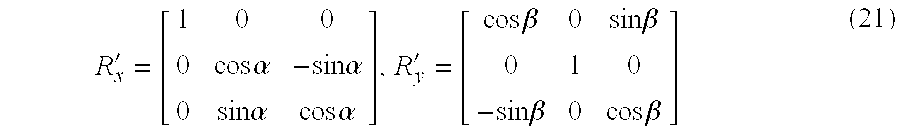
- FIG. 17 shows a representation of the perspective projection by using the rotation matrix. As shown in FIG. 17, the meaning of the above formulas (20) and (21) is the same as the transformation of the apparatus coordinate system (x, y, z) into a new coordinate system (x′, y′, z′) by the two stages of rotation: (i) and (ii), which follows.
- (i) The apparatus coordinate system 33 (x, y, z) is transformed into an intermediate coordinate system (x1, y1, z1) by rotating the apparatus coordinate
system 33 around the y axis by a rotation angle “β”. - (ii) The intermediate coordinate system (x 1, y1, z1) is transformed into the new coordinate system (x′, y′, z′) by rotating the intermediate coordinate system around the x1 axis by a rotation angle “α”.
- By using the above formulas (19) and (20), the rotation angles “α” and “β” are represented by the following formulas.
- α=sin−1(−b) (22)
-

- From the above formulas (22) and (23), the rotation angles “α” and “β” are calculated, and the resulting rotation angles “α” and “β” are substituted into the above formulas (20) and (21). This allows the rotation matrix “R′” to be uniquely determined. The rotation matrix “R′” represents the coordinate transformation in which the z axis of the apparatus coordinate
system 33 is transformed so as to accord with the direction of the unit binormal vector. - Next, a description will be provided of the calculation of the distortion correction parameters performed by the
parameter computing unit 222 in the present embodiment. - As described above, the calculation of the distortion correction parameters is essentially the same as the determination of the perspective projection formula, and each of the pixels of the standard image on the image surface is projected into a pixel on the projection plane by using the perspective projection formula.
- To determine the perspective projection formula, a 3D vector “P” expressed on the basis of the apparatus coordinate
system 33 at the viewpoint when taking the standard image, the above-described rotation matrix “R′” and the 3D vector “n”=(a, b, c) indicating the direction of the object plane are used. The 3D vector “P” corresponding to one pixel of the standard image on the image surface, as shown in FIG. 15, is extended to the projection plane. Suppose that the point “P”, where the extended vector “P” intersects the projection plane, corresponds to a pixel of the image projected onto the projection plane after the coordinate transformation. The 3D vector “P” corresponding to the point “P” on the basis of the apparatus coordinatesystem 33 is represented by
- In the above formula (24), “k” denotes a scaling factor that is indicative of a distance from the optical system center “o” of the
imaging unit 11 to the projection plane. Hence, the determination of the scaling factor “k” defines the size of the distortion-corrected image created on the projection plane. The 3D vector “P” in the above formula (24) is expressed on the basis of the apparatus coordinatesystem 33 at the viewpoint when taking the standard image. By applying the rotation matrix “R′” to the 3D vector “P” as in the following formula, the 3D vector “P” is transformed into a 3D vector “P′” on the basis of the apparatus coordinate system when theimaging unit 11 faces the object plane from the direction perpendicular to the object plane.
- The coordinates (X, Y) of the 3D vector “P′” in the above formula (25) are used as the coordinates of the pixel on the projection plane after the coordinate transformation is performed. Accordingly, each of the pixels of the standard image on the image surface can be projected into the pixel on the projection plane by using the perspective projection formula (25), and the coordinates of each of the pixels of the distortion-corrected image on the projection plane can be obtained. In this manner, the
parameter computing unit 222 performs the calculation of the distortion correction parameters by using the perspective projection formula (25). - Finally, in the
IDC 22 of FIG. 11, the coordinatetransform unit 223 creates a distortion-corrected image on the projection plane by projecting the standard image onto the projection plane through the perspective projection based on the parameters supplied by theparameter computing unit 223. - Specifically, in the present embodiment, the coordinates (x s, ys) of each of the pixels of the standard image corresponding to the coordinates (X, Y) after the coordinate transformation are calculated by using the above formula (25), and the pixel value at the coordinate (X, Y) is estimated or interpolated based on the pixel values at the neighboring pixels in the vicinity of the calculated coordinates (xs, ys) of that pixel. The interpolation of the pixel value at the coordinate (X, Y) based on the pixel values at the neighboring pixels of the calculated coordinates (xs, ys) can be carried out by using a known interpolation method, such as the bilinear interpolation or the B-spline interpolation.
- Accordingly, in the image processing method and apparatus of the present embodiment, even when the original image of the object on the object plane is taken from different oblique directions, the correction of the image distortions due to the oblique imaging can be carried out by taking at least two object images (the
standard image 7 and thereference image 9 as shown in FIG. 14). By using theSIS 20, one of the plurality of partially overlapping images, having the largest ratio of the object region area to the entire image area, can be easily and suitably selected as the standard image. The image processing method and apparatus of the present embodiment can provide an improved operability for the user. - Further, in the present embodiment, the program code instructions for causing the
main control unit 14 to execute the image distortion correction processing of FIG. 5 are stored in, for example, a ROM of themain control unit 14. Upon start of the execution of the image distortion correction processing, the program code instructions are loaded from the ROM to a RAM of themain control unit 14, and the image distortion correction is carried out by themain control unit 14. Hereinafter, themain control unit 14 will be referred to as the computer, for the sake of convenience. - Next, FIG. 18A and FIG. 18B show an image distortion correction of a second preferred embodiment of the image processing method of the invention.
- As shown in FIG. 18A, the image processing method of the present embodiment is used to sequentially take “K” partially overlapping still images of an object on the object plane PL at “K” different viewpoints. For example, the image of the object taken from an oblique direction “d 1” will be referred to as the image “im1”, the image of the object taken from an oblique direction “d2” will be referred to as the image “im2”, and so on. The two adjacent images among the “K” images, such as the image “im1” and the image “im2”, share a common location of the original image on the object plane PL. In the present embodiment, respective images (one of which is referred to as the image “imj”, 1≦j≦K), which are projected onto an image surface of the image “imk” with respect to each of the “K” images, are combined to the image “imk” so as to form a composite image “IMC” on the image surface of the image “imk” as shown in FIG. 18B. Further, the composite image “IMC” is projected onto the projection plane by using the perspective projection, so that the image distortions caused by the oblique imaging are corrected.
- FIG. 19 shows a second preferred embodiment of the image processing apparatus of the invention. In FIG. 19, the elements that are essentially the same as corresponding elements in FIG. 3 are designated by the same reference numerals, and a description thereof will be omitted.
- As shown in FIG. 19, the
image processing apparatus 6 of the present embodiment is essentially the same as theimage processing apparatus 1 of the previous embodiment of FIG. 3, except that an image composite unit (IC) 24 is provided instead of theIDC 22 as in the previous embodiment of FIG. 3. In the present embodiment, theIC 24 combines the other partially overlapping images, which are projected onto an image surface of the standard image with respect to each of the other partially overlapping images, so that a composite image is generated on the image surface, so as to correct the image distortions in the standard image. Similar to the previous embodiment of FIG. 3, theCD 21 determines the feature point of one of the plurality of partially overlapping points, and determines a matched point of one of the other partially overlapping images. TheIC 24 calculates a direction of the object plane is calculated based on the feature point and the matched point determined by theCD 21. - FIG. 20 is a flowchart for explaining operation of the
image processing apparatus 6 of the present embodiment. - As shown in FIG. 20, the
main control unit 14 at step S1 determines whether the distortion correcting mode is selected by the user by turning ON themode setting key 104. When the result at the step S1 is negative, step S10 sets theimage processing apparatus 1 in the normal imaging mode wherein a snap photograph of a desired object is taken. - When the result at the step S 1 is affirmative, step S2 requests the user to input the object image, which is taken from the original image of an object on the object plane PL by using the
imaging unit 11. It is necessary that a plurality of object images be input to theimage processing apparatus 1, the plurality of object images including at least a pair of partially overlapping first and second images that are taken from different oblique directions, and the two images sharing a common location of the original image on the object plane PL. - Step S 3 determines whether the inputting of the object image to the
image processing apparatus 1 is finished according to the user's operation. When the result at the step S3 is negative, the control is transferred to the step S2. The inputting of the object image to theimage processing apparatus 1 is repeated until the result at the step S3 is affirmative. When the result at the step S3 is affirmative, the control is transferred to the next step S4. In the present embodiment, the above-mentioned operation is performed by turning ON the mode setting key 104 again. - After the inputting of the plurality of object images (or the partially overlapping first and second images) to the
image processing apparatus 1 is performed, step S4 performs the setting of a standard image. In this step, one of the plurality of object images is manually or automatically selected as the standard image that contains the smallest amount of image distortions among the plurality of partially overlapping images. In the present embodiment, the standard image setting unit (SIS) 20 carries out the setting of the standard image at the step S4, which is the same as that in the previous embodiment of FIG. 5. For the sake of convenience, suppose that the image “imj” in the example of FIG. 18 is selected as the standard image, and that the image “imj” has the smallest amount of image distortions among the plurality of partially overlapping images “im1” through “imk”. - After the step S 4 is performed, the main control unit (CTR) 14 at step S5 controls the correspondence detecting unit (CD) 21 so that the
CD 21 determines a feature point of the standard image (or the selected one of the plurality of partially overlapping images) corresponding to the common location of the original image, and determines a matched point of one of the other partially overlapping images corresponding to the feature point. After the step S5 is performed, step S6 performs the computation of the perspective projection transform matrix. After the step S6 is performed, step S7 generates a composite image on the image surface of the standard image so as to correct the image distortions in the standard image. After the step S7 is performed, the process of FIG. 20 ends. - In the present embodiment, the
IC 24 performs the computation of the perspective projection transform matrix and the creation of the composite image, which will be described later. - FIG. 21 is a block diagram of the image composition unit (IC) 24 in the image processing apparatus of FIG. 19.
- As shown in FIG. 21, the
IC 24 generally includes a projectiontransform computing unit 231 and a coordinatetransform unit 241. In theimage processing apparatus 6 of the present embodiment, theSIS 20 andCD 21 are connected to inputs of the projectiontransform computing unit 231. TheSIS 20, theFM 15 and the projectiontransform computing unit 231 are connected to inputs of the coordinatetransform unit 241. - In the
IC 24 of FIG. 21, the projectiontransform computing unit 231 calculates the 3D data of the object plane and the 3D data of the respective image surfaces of the “K” images based on the relation between the feature point and the matched point supplied by the correspondence detecting unit (CD) 21. The projectiontransform computing unit 231 calculates the distortion correction parameters based on the 3D data of the object plane and the 3D data of the respective image surfaces. - Further, the coordinate
transform unit 232 creates a distortion-corrected composite image on the projection plane by projecting the composite image onto the projection plane through the perspective projection based on the parameters supplied by the projectiontransform computing unit 231. For the creation of the distortion-corrected composite image, the coordinatetransform unit 232 uses the (K-1) perspective projection matrixes B1, B2, . . . , BK-1 for the (K-1) pairs of the standard image and the reference image, which are supplied by theFM 15. - More specifically, the perspective projection matrix for projecting the image “imn” (n=1 to k- 1) onto the image “im(n+1)” is represented by “Bn”, and the perspective projection matrix for projecting the image “imn” onto the image “imj” is represented by
- B n→j
- The projection
transform computing unit 231 calculates the perspective projection matrixes based on the following formula:
- The projection
transform computing unit 231 calculates a set of 3D parameters {R, t, n} of the object plane and the image surfaces of the standard image and the reference image for each (called the image “J”) of the “K” images based on the relation between the feature point and the matched point supplied by theCD 21. Theprojection transform computing 231 uses the following perspective projection matrix B for each of the “K” images, and performs the calculations of the above formula (26) to obtain the 3D parameters {R, t, n} for each of the “K” images. - The
projection transform computing 231 of the present embodiment performs the calculations of the above formula (26) based on the 3D data of the object plane and the 3D data of the image surfaces (or the 3D parameters {R, t, n}), in order to obtain the distortion correction parameters. - The coordinate
transform unit 232 of the present embodiment generates the distortion-corrected composite image on the projection plane by projecting the composite image onto the projection plane through the perspective projection based on the 3D parameters supplied by the projectiontransform computing unit 231. More specifically, in the present embodiment, the coordinates (xs, ys) of each of the pixels of the standard image corresponding to the coordinates (X, Y) after the coordinate transformation are calculated by using the following formula,
- In the above formula (27), “s” is a coefficient that makes the value of the third element of the left-side vector of the formula (27) equal to 1. Next, the pixel value at the coordinate (X, Y) is estimated or interpolated based on the pixel values at the neighboring pixels in the vicinity of the calculated coordinates (x s, ys) of that pixel. The interpolation of the pixel value at the coordinate (X, Y) based on the pixel values at the neighboring pixels of the calculated coordinates (xs, ys) can be carried out by using the known interpolation method, such as the bilinear interpolation or the B-spline interpolation.
- In the above-described embodiment, the standard image is selected from the plurality of partially overlapping images after the inputting of the partially overlapping images (the object images) is performed. Alternatively, the selection of the standard image may be performed before the inputting of the partially overlapping images (the object images) is performed. A description will now be given of a third preferred embodiment of the image processing apparatus of the invention in which the selection of the standard image is performed before the inputting of the object images is performed.
- FIG. 22 is a block diagram of the third preferred embodiment of the image processing apparatus of the invention. In FIG. 22, the elements that are essentially the same as corresponding elements in FIG. 3 are designated by the same reference numerals, and a description thereof will be omitted.
- As shown in FIG. 22, the
image processing apparatus 8 of the present embodiment is essentially the same as theimage processing apparatus 1 of the previous embodiment of FIG. 3, except that a notification unit (NTF) 26 and a finder (FND) 241 are provided in addition to the elements in the previous embodiment of FIG. 3. In the present embodiment, theSIS 20 is configured such that a user is requested to select the standard image when taking the original image from one of the oblique directions. Thenotification unit 26 notifies the user that the standard image is currently taken, which will be described later. - In the
image processing apparatus 8 of FIG. 22, thenotification unit 26 is connected to each of themain control unit 14 and theSIS 20. Further, theshutter 113 of theimaging unit 11 and theinterface unit 16 are connected to themain control unit 14, and thefinder 241 and theinterface unit 16 are connected to each other. - FIG. 23 is a flowchart for explaining operation of the
image processing apparatus 8 of the present embodiment. FIG. 24 is a diagram for explaining standard image setting operations that are provided to theSIS 20 in theimage processing apparatus 8 of FIG. 22. FIG. 25 is a diagram for explaining operation of thenotification unit 26 in theimage processing apparatus 8 of FIG. 22. - As shown in FIG. 23, the
main control unit 14 at step SI determines whether the distortion correcting mode is selected by the user by turning ON themode setting key 104. When the result at the step S1 is negative, step S10 sets theimage processing apparatus 1 in the normal imaging mode wherein a snap photograph of a desired object is taken. - When the result at the step S 1 is affirmative, step S2 controls the
SIS 20 so that theSIS 20 performs the setting of a standard image. In this step, one of the plurality of object images is manually or automatically selected as the standard image that contains the smallest amount of image distortions among the plurality of partially overlapping images. In the present embodiment, theSIS 20 carries out the setting of the standard image at the step S2, which is the same as that in the previous embodiment of FIG. 5. As shown in FIG. 24, theSIS 20 is provided withcursor keys 204 and theenter key 203. At the step S2, the operational message “STANDARD IMAGE SETTING” is displayed on thedisplay unit 17, as well as the number of the object images taken by the user, and the identification of the standard image set by the user. - After the step S 2 is performed, step S3 requests the user to input the object image, which is taken from the original image of an object on the object plane PL by using the
imaging unit 11. When the object image is input to theimage processing apparatus 8, the main control unit at step S4 determines whether the standard image is taken from the original image by the user. When theenter key 203 is turned ON by the user after the setting of the standard image is done, the result at the step S4 is affirmative, and the control is transferred to the next step S5. Otherwise the result at the step S4 is negative, and the control is transferred to the step S6 and the step S5 is not performed. - Step S 5 controls the
finder 241 so that thefinder 241 notifies the user that the standard image is currently taken. As shown in FIG. 25, anappropriate indicator 242 is displayed on thefinder 241 at a sidewise location of theobject image 35 within thefinder 241. - After the step S 5 is performed, step S6 determines whether the inputting of the object image to the
image processing apparatus 1 is 5 finished according to the user's operation. When the result at the step S6 is negative, the control is transferred to the step S3. The inputting of the object image to theimage processing apparatus 1 is repeated until the result at the step S6 is affirmative. When the result at the step S6 is affirmative, the control is transferred to the next step S7. - After the inputting of the plurality of object images (or the partially overlapping first and second images) to the
image processing apparatus 1 is performed, the main control unit (CTR) 14 at step S7 controls theCD 21 so that theCD 21 determines a feature point of the standard image (or the selected one of the plurality of partially overlapping images) corresponding to the common location of the original image, and determines a matched point of one of the other partially overlapping images corresponding to the feature point. After the step S7 is performed, step S8 performs the computation of the perspective projection transform matrix. After the step S8 is performed, step S9 generates controls at step S7 theIDC 22 so that theIDC 22 generates a distortion-corrected image on the projection plane, which is parallel to thee object plane, by projecting the standard image onto the projection plane through a perspective projection based on the calculated direction of the object plane. That is, the distortion-corrected image created by theIDC 22 is essentially the same as the image of the object that is taken by theimaging unit 11 from the direction perpendicular to the object plane, not from the oblique direction. After the step S9 is performed, the process of FIG. 23 ends. - According to the
image processing apparatus 8 of the present embodiment, it is possible to provide an improved operability for the user in performing the selection of the standard image from the plurality of partially overlapping images. - FIG. 26 is a block diagram of a fourth preferred embodiment of the image processing apparatus of the invention.
- As shown in FIG. 26, the
image processing apparatus 40 of the present embodiment generally includes animaging device 41, the signal processing unit (SP) 12, the memory control unit (MC) 13, the main control unit (CTR) 14, the frame memory (FM) 15, the interface unit (I/F) 16, the display unit (DP) 17, the external storage (ES) 18, the mode setting unit (MS) 19, the standard image setting unit (SIS) 20, the correspondence detecting unit (CD) 21, and the image distortion correcting unit (IDC) 22. In the present embodiment, theimaging device 41 is configured to include afirst imaging unit 11A and asecond imaging unit 11B. Each of the first andsecond imaging units optical system elements 111 through 115 that are essentially the same as corresponding elements of theimaging unit 11 in the previous embodiment of FIG. 3. - FIG. 27 is a flowchart for explaining operation of the
image processing apparatus 40 of the present embodiment. FIG. 28 is a diagram for explaining standard image setting operations that are provided to theSIS 20 in theimage processing apparatus 40 of FIG. 26. - As shown in FIG. 27, the
main control unit 14 at step S1 determines whether the distortion correcting mode is selected by the user by turning ON themode setting key 104. When the result at the step S1 is negative, step S10 sets theimage processing apparatus 1 in the normal imaging mode wherein a snap photograph of a desired object is taken. - When the result at the step S 1 is affirmative, step S2 controls the
SIS 20 so that theSIS 20 performs the setting of a standard image. In this step, one of the plurality of object images is manually or automatically selected as the standard image that contains the smallest amount of image distortions among the plurality of partially overlapping images. In the present embodiment, theSIS 20 carries out the setting of the standard image at the step S2, which is the same as that in the previous embodiment of FIG. 5. As shown in FIG. 28, theSIS 20 is provided with the upscroll key 201, thedown scroll key 202 and theenter key 203. At the step S2, the operational message “STANDARD IMAGE SETTING” is appears on thedisplay unit 17 together with the two indicators “CAMERA 1” (corresponding to thefirst imaging unit 11A) and “CAMERA 2” (corresponding to thesecond imaging unit 11B) for the user's choice of the setting of the standard image. - After the step S 2 is performed, step S3 requests the user to input the object image, which is taken from the original image of an object on the object plane PL by using the selected one of the
imaging units image processing apparatus 8, the main control unit determines that the standard image is taken from the original image by the user. When theenter key 203 is turned ON by the user after the setting of the standard image is done, the control is transferred to the next step S4. - After the inputting of the plurality of object images (or the partially overlapping first and second images) to the
image processing apparatus 1 is performed, the main control unit (CTR) 14 at step S4 controls theCD 21 so that theCD 21 determines a feature point of the standard image (or the selected one of the plurality of partially overlapping images) corresponding to the common location of the original image, and determines a matched point of one of the other partially overlapping images corresponding to the feature point. After the step S4 is performed, step S5 performs the computation of the perspective projection transform matrix. After the step S5 is performed, step S6 controls theIDC 22 so that theIDC 22 generates a distortion-corrected image on the projection plane, which is parallel to thee object plane, by projecting the standard image onto the projection plane through a perspective projection based on the calculated direction of the object plane. After the step S6 is performed, the process of FIG. 27 ends. - According to the
image processing apparatus 40 of the present embodiment, theimaging device 41, including the first andsecond imaging units 11 a and 11B, is used, and it is possible to provide a further improved operability for the user in performing the selection of the standard image from the plurality of partially overlapping images. - Further, the
imaging device 41 in theimage processing apparatus 40 of FIG. 26 may include three or more imaging units, each including the optical system that is essentially the same as that of the previous embodiment of FIG. 3. Theimaging device 41 of the present embodiment may be applied to theimage processing apparatus 6 of the previous embodiment of FIG. 19. - Further, in the above-described embodiments, the plurality of partially overlapping images, which are recorded onto a storage medium such as a hard disk or a CD-ROM, may be read and loaded to the external storage (ES) 18 of the image processing apparatus. The image distortion correcting processing that is the same as that of the above-described embodiments can be carried out with the plurality of partially overlapping images stored in the
ES 18. Further, in the above-described embodiments, theMS 19, theSIS 20, theCD 21, theIDC 22, and theIC 24 may be provided in the image processing apparatus such that they are separated from theimaging unit 11 or theimaging device 41. - FIG. 29 is a block diagram of a fifth preferred embodiment of the image processing apparatus of the invention.
- As shown in FIG. 29, the
image processing apparatus 50 of the present embodiment is configured such that an object region determining unit (ORD) 25 and a standard image automatic setting unit (SIAS) 27 are provided instead of theSIS 20 of FIG. 3, theORB 25 and theSIAS 27 are connected to themain control unit 14, an output of theORB 25 is connected to theSIAS 27, and an output of theSIAS 27 is connected to theIDC 22. - FIG. 30 is a flowchart for explaining operation of the
image processing apparatus 50 of the present embodiment. - As shown in FIG. 30, the
main control unit 14 at step S1 determines whether the distortion correcting mode is selected by the user by turning ON themode setting key 104. When the result at the step S1 is negative, step S10 sets theimage processing apparatus 1 in the normal imaging mode wherein a snap photograph of a desired object is taken. - When the result at the step S 1 is affirmative, step S2 requests the user to input, to the
image processing apparatus 50, the object image taken from the original image of the object on the object plane. It is necessary that the plurality of object images be input to theimage processing apparatus 50, the plurality of object images including at least a pair of partially overlapping first and second images which share a common location of the original image on the object plane. - After the step S 2 is performed, step S3 determines whether the inputting of the object image to the
image processing apparatus 50 is finished according to the user's operation. When the result at the step S3 is negative, the control is transferred to the step S2. The inputting of the object image to theimage processing apparatus 50 is repeated until the result at the step S3 is affirmative. - When the result at the step S 3 is affirmative, the
main control unit 14 at step S4 controls theCD 21 so that theCD 21 theCD 21 determines a feature point of the standard image (or the selected one of the plurality of partially overlapping images) corresponding to the common location of the original image, and determines a matched point of one of the other partially overlapping images corresponding to the feature point. - After the step S 4 is performed, step S5 controls the
SIAS 27 so that theSIAS 27 performs the automatic setting of a standard image. In this step, one of the plurality of object images is automatically selected as the standard image that contains the smallest amount of image distortions among the plurality of partially overlapping images. In the present embodiment, theSIAS 20 carries out the automatic setting of the standard image, at the step S5, based on the feature point and the matched point determined by theCD 21. - After the step S 5 is performed, step S6 controls the
IDC 22 so that theIDC 22 performs the computation of the image distortion correcting parameters based on the feature point and the matched point determined by theCD 21. After the step S6 is performed, step S7 controls theIDC 22 so that theIDC 22 generates a distortion-corrected image on the projection plane, which is parallel to thee object plane, by projecting the standard image onto the projection plane through a perspective projection based on the calculated direction of the object plane. After the step S7 is performed, the process of FIG. 30 ends. - According to the
image processing apparatus 50 of the present embodiment, the standard imageautomatic setting unit 27 is provided to automatically select one of the plurality of partially overlapping images as the standard image based on the feature point and the matched point determined by theCD 21, and it is possible to provide a further improved operability for the user in performing the selection of the standard image from the plurality of partially overlapping images. - FIG. 31A and FIG. 31B are diagrams for explaining an image distortion that depends on the degradation of the resolution of the image processing apparatus.
- The
IDC 22 of theimage processing apparatus 50 of FIG. 29 performs the coordinate transformation according to the above formula (25) so that the creation of a distortion-corrected image is performed. Generally, the operation of the image distortion correction is varied depending on the degradation of the resolution of the image processing apparatus. For the sake of simplicity of description, suppose that the inclination angle φ between the direction of the object plane and the direction of the image surface is variable only around the y-axis direction, and that the size of theprojection plane 31, which is parallel to the object plane, is equal to the size of theimage surface 32. - As shown in FIG. 31A, when the inclination angle φ is relatively small, the point in the vicinity of the left-end edge of the
image surface 32 is projected onto theprojection plane 31, which is indicated by a change of the vector toward the origin “o” of the coordinate system. In this case, the resolution of the object image will be degraded by the coordinate transformation. - As shown in FIG. 31B, when the inclination angle φ is relatively large, the point in the vicinity of the left-end edge of the
image surface 32 is projected onto theprojection plane 31, which is indicated by a larger change of the vector toward the origin “o” of the coordinate system. In this case, the range in which the resolution of the object image will be degraded by the coordinate transformation is increased as indicated by the shaded area in FIG. 31B. - In the
image processing apparatus 50 of FIG. 29, theORD 25 acquires an object region of the object image, taken by theimaging unit 11, by using the image segmentation process, which is known from the above-mentioned document “Computer Image Processing and Recognition”. In the document, four kinds of the image segmentation method: (a) clustering is performed on the image (e.g., the region division method); (b) clustering is performed on the characteristic space (e.g., the histogram based region division method); (c) edges of the image are used (e.g., contour line tracing); (d) texture analysis are explained. An appropriate one of the image segmentation methods is applied to theORD 25 of theimage processing apparatus 50. When the image segmentation is performed, the image of the object is divided into regions of picture elements, the individual regions having distinctive intensity characteristics depending on the image taken by the imaging device. If the object surface is rectangular and the coordinates of the vertexes of the four corners of the object in the image are externally supplied to theORD 25, the object region can be uniquely determined by theORD 25. - In the
image processing apparatus 50 of FIG. 29, the data signal indicating the object region determined by theORD 25 is supplied to theIDC 22 through theSIAS 27. In response to the received data signal, theIDS 22 automatically selects the object image having the largest ratio of the area of the object region to the entire area of the image as the standard image from among the plurality of object images (or the partially overlapping first and second images). - FIG. 32 is a block diagram of a variation of the fifth preferred embodiment of the image processing apparatus. As shown in FIG. 32, the
image processing apparatus 51 of the present embodiment is configured such that a straight-line pattern detecting unit (SLPD) 28 is provided instead of theORD 25 of FIG. 29, theSLPD 28 and theSIAS 27 are connected to themain control unit 14, and theSLPD 28 is connected to theIDC 22 through theSIAS 27. - In the
image processing apparatus 51 of FIG. 32, theSLPD 28 detects a direction of a straight-line pattern contained in the object image, taken from the original image of the object on the object plane by applying the straight-line pattern to the following formula. - ax+by+c=0 (a 2 +b 2=1) (28)
- Based on the direction of the straight-line pattern detected by the
SLPD 28, theIDC 22 automatically selects one of the plurality of object images (or the partially overlapping first and second images) as the standard image. - FIG. 33 is a diagram for explaining Hough transform used by the image processing method of the present embodiment.
- Alternatively, in the
image processing apparatus 51 of FIG. 32, theSLPD 28 detects a direction of a straight-line pattern contained in the object image, taken from the original image of the object on the object plane by subjecting each object image to the Hough transform as shown in FIG. 33. - As indicated by FIG. 33( a) and (b), a sequence of points P1, P2 and P3 on the object image are projected onto the θ-ρ space. In the θ-ρ space, a corresponding line (L1, L2 or L3) for each point is represented by a combination of the angle θ of the point in the x-y coordinate system and the length ρ of a line segment between the origin “o” of the x-y coordinate system and the point. As shown in FIG. 33(b), the intersection point CP (θ,ρ) of the transformed lines is assumed, and the
SLPD 28 of the present embodiment detects a direction of a straight-line pattern contained in the object image, taken from the original image of the object on the object plane by using the following formula. - ρ=xcosθ+ycosθ (29)
- In the present embodiment, based on the direction of the straight-line pattern detected by the
SLPD 28, theIDC 22 automatically selects one of the plurality of object images (or the partially overlapping first and second images) as the standard image. - FIG. 34 is a block diagram of another variation of the fifth preferred embodiment of the image processing apparatus.
- As shown in FIG. 34, the
image processing apparatus 52 of the present embodiment is configured such that only the standard image automatic setting unit (SIAS) 27 is provided while theORD 25 of FIG. 29 or theSLPD 28 of FIG. 32 is not provided, and theSIAS 27 is connected to theIDC 22. - In the present embodiment, the
SIAS 27 is provided to automatically select one of the plurality of partially overlapping images as the standard image based on the feature point and the matched point determined by theCD 21, and it is possible to provide an improved operability for the user in performing the selection of the standard image from the plurality of partially overlapping images. TheIDC 22 performs the coordinate transformation according to the above formula (25) so that the creation of a distortion-corrected image is performed. - FIG. 35 is a block diagram of another variation of the fifth preferred embodiment of the image processing apparatus.
- As shown in FIG. 35, the
image processing apparatus 53 of the present embodiment is configured such that a flat-surface measuring unit (FSM) 29 is provided in addition to the SIAS 27 (which is provided instead of theORD 25 of FIG. 29 or theSLPD 28 of FIG. 32), theFSM 29 is connected to theSIAS 27, and theSIAS 27 is connected to theIDC 22. - In the present embodiment, the
FSM 29 measures a direction of the object plane when theimaging unit 11 takes the object image from the original image. FIG. 36 is a block diagram of the flat surface measuring unit (FSM) 29 in theimage processing apparatus 53 of FIG. 35. As shown in FIG. 36, theFSM 29 generally includes a spot light source 271, aphotodetector 272, a 3D coordinatecomputing unit 273, and a flatsurface computing unit 274. The spot light source 271 includes alight source 271 a (for example, a light emitting diode or a semiconductor laser), ascanning mirror 271 b (for example, a polygonal mirror), and ascanning mirror actuator 271 c. - As shown in FIG. 36, in the
FSM 29 of the present embodiment, the light emitted by thelight source 271 a is reflected at thescanning mirror 271 b to the object plane PL. Theactuator 271 c controls the direction of thescanning mirror 271 b so that a light spot is formed on the object plane PL by the reflected light beam from thescanning mirror 271 b. Thephotodetector 272 is provided at a given location relative to the spot light source 271, and thephotodetector 272 is constituted by a position sensitive detector (PSD) or a charge-coupled device (CCD) arranged at the given location. A reflection light beam from the light spot on the object plane PL is received at thephotodetector 272, and thephotodetector 272 detects a direction of the reflection light beam received from the object plane PL. - Alternatively, the above-described
photodetector 272 may be constituted by using thephotoelectric conversion unit 114 of theimaging unit 11. - The 3D coordinate
computing unit 273 calculates the 3D coordinates (X, Y, Z) of the object plane PL on the basis of the apparatus coordinate system of theimage processing apparatus 53, based on the direction of the light beam emitted by the spot light source 271, the positional relationship of the spot light source 271 and thephotodetector 272, and the detected direction of the reflection light beam obtained at thephotodetector 272. The flat-surface computing unit 274 generates an estimated surface equation - aX+bY+cZ+d=0 (a 2 +b 2 +c2=1, c>0) (30)
- based on the calculated 3D coordinates supplied by the 3D coordinate
computing unit 273. The flat-surface computing unit 274 calculates the four parameters (a, b, c, d) of the surface equation by using the least square method. As a result of the calculation, the flat-surface computing unit 274 generates an inclination angle φ that corresponds to the direction of the object plane PL in accordance with the following formula - φ=cos−1 c (31)
- In the
image processing apparatus 53 of FIG. 35, theFSM 29 supplies the calculated direction of the object plane with respect to each of the plurality of partially overlapping images, to theSIAS 27. In the present embodiment, theSIAS 27 is provided to automatically select one of the plurality of partially overlapping images as the standard image that has the smallest inclination angle φ among the plurality of partially overlapping images, based on the measured direction of the object plane supplied by theFSM 29, and it is possible to provide an improved operability for the user in performing the selection of the standard image from the plurality of partially overlapping images. - FIG. 37 is a block diagram of a sixth preferred embodiment of the image processing apparatus of the invention.
- As shown in FIG. 37, the
image processing apparatus 60 of the present embodiment is essentially the same as theimage processing apparatus 6 of FIG. 19, except that the standard image automatic setting unit (SIAS) 27 is provided instead of theSIS 20 as in the previous embodiment of FIG. 19. - FIG. 38 is a flowchart for explaining operation of the
image processing apparatus 60 of the present embodiment. The image distortion correction processing performed by theimage processing apparatus 60 of the present embodiment is essentially the same as the image distortion correction processing performed by theimage processing apparatus 50 which is shown in FIG. 30, except that the step S6 performs the computation of the perspective projection transform matrix, and that the step S7 generates a composite image on the image surface of the standard image so as to correct the image distortions in the standard image. - In the present embodiment, the
SIAS 27 is provided to automatically select one of the plurality of partially overlapping images as the standard image based on the feature point and the matched point determined by theCD 21, and theIC 24 performs the computation of the perspective projection transform matrix and the creation of the composite image. - FIG. 39 is a block diagram of a seventh preferred embodiment of the image processing apparatus of the invention.
- As shown in FIG. 39, the
image processing apparatus 70 of the present embodiment is essentially the same as theimage processing apparatus 1 of FIG. 3, except that the standard image automatic setting unit (SIAS) 27 and a switching unit (SW) 45 are additionally provided. The main control unit (CTR) 14 controls theSIAS 27. TheSIS 20 and theSIAS 27 are connected to inputs of theSW 45, and an output of theSW 45 is connected to theIDC 22. - In the present embodiment, the
SW 45 is provided to select one of theSIS 20 and theSIAS 27 for setting of the standard image among the plurality of partially overlapping images. FIG. 40 shows is a diagram for explaining operation of the switchingunit 45 in theimage processing apparatus 70 of FIG. 39. As shown in FIG. 40, the switchingunit 45 is provided with the upscroll key 201, thedown scroll key 202 and theenter key 203. When a menu key (not shown), which is indicated on thedisplay unit 17, is turned ON by the user, the operational message “STANDARD IMAGE SELECTION” appears on thedisplay unit 17 together with the two indicators “AUTO” and “MANUAL” for the user's choice for setting of the standard image setting method. By using thescroll key enter key 203 is turned ON. Then, either the manual setting of the standard image by theSIS 20 or the automatic setting of the standard image by theSIAS 27 is activated by the switchingunit 45 based on the user's selection, and the activated one is connected to theIDC 22 through the switchingunit 45. - FIG. 41 shows a computer-readable storage medium for use in the image processing apparatus of the invention. As shown in FIG. 41, a computer-
readable storage medium 301, which stores the program code instructions for causing the main control unit 14 (or the computer) of theimage processing apparatus 1 of the present invention, may be used with the image processing apparatus. The program code instructions, stored in thestorage medium 301, are provided to execute the image distortion correcting processing of the invention. The program code instructions of thestorage medium 301 are read by themain control unit 14, and they are loaded into the RAM of themain control unit 14. Then, the execution of the image distortion correcting processing is started by themain control unit 14. - FIG. 42 shows a computer-readable storage medium for use in a personal computer to which the image processing method of the invention is applied.
- As shown in FIG. 34, the image processing method of the present invention is applied to a personal computer PC. The program code instructions for causing the CPU of the PC to execute the image distortion correction processing of the invention are stored in a computer-readable storage medium, which is, for example, a CD-
ROM 302. The program code instructions of the CD-ROM 302 are read by the CPU of the personal computer PC by using a disk drive of the PC and the program code instructions are loaded into the RAM of the PC before a start of the execution of the image distortion correction processing. Then, the execution of the image distortion correction processing is started by the CPU of the personal computer PC. - Alternatively, the program code instructions, read from the CD-
ROM 302, may be temporarily stored in a secondary storage (not shown) of the personal computer PC. At a start of the execution of the image distortion correction processing when the necessity occurs, the program code instructions are loaded into the RAM of the personal computer PC. - The image signals, which indicate the respective images of the object taken by the
image processing apparatus 1, are transmitted to the image memory of the personal computer PC via a communication port, and the image signals are processed by the CPU of the personal PC. Alternatively, the image signals, which indicate the respective images of the object taken by theimage processing apparatus 1, may be temporarily stored in a secondary recording medium, such as an IC memory. When the necessity occurs, the image signals, stored in the IC memory, are loaded into the image memory of the personal computer PC. The user on the image processing apparatus of the present invention sends a command to the CPU of the personal computer PC (or the program code instructions) by using an input device, such as a mouse or a keyboard, and receives a message from the CPU of the personal computer PC by using an output device, such as a display monitor or a printer. - It should be noted that the image processing method and apparatus of the invention may be implemented in any of several configurations. The
imaging unit 11 and theimage processing apparatus 1 may be incorporated into a digital still camera. Alternatively, theimaging unit 11 and a portion of theimage processing apparatus 1 may be incorporated into a digital still camera, and the remaining portion of theimage processing apparatus 1 may be incorporated as the program code instructions stored in a computer-readable storage medium. Alternatively, theimaging unit 11 may be incorporated into a digital still camera, and theimage processing apparatus 1 may be incorporated as a personal computer connected to the digital still camera or connected to the IC memory. - Further, when the image processing apparatus is divided into a block that is incorporated into a digital still camera and a block that is incorporated into a separate image processing apparatus, an arbitrary one of various possible configurations of the image processing system, in which the image processing apparatus is divided into such blocks while the manufacturing cost and the purpose of the application are taken into consideration, can be chosen freely.
- The present invention is not limited to the above-described embodiments, and variations and modifications may be made without departing from the scope of the present invention. For example, the respective elements of the image processing apparatus of the invention may be incorporated as the program code instructions stored in a portable computer readable medium, such as floppy disk or CD-RW, and, when the necessity occurs, the program code instructions may be loaded from the portable computer readable medium into the computer. Alternatively, the respective elements of the image processing apparatus of the invention may be incorporated as the program code instructions stored in an external storage of the computer, and when the necessity occurs, the program code instructions may be loaded from the external storage into the computer.
- Further, the present invention is based on Japanese priority application No. 11-375651, filed on Dec. 28, 1999, and Japanese priority application No. 2000-261565, filed on Aug. 30, 2000, the entire contents of which are hereby incorporated by reference.
Claims (16)
Applications Claiming Priority (2)
| Application Number | Priority Date | Filing Date | Title |
|---|---|---|---|
| JP2000-261565 | 2000-08-30 | ||
| JP2000261565A JP4169464B2 (en) | 1999-12-28 | 2000-08-30 | Image processing method, image processing apparatus, and computer-readable recording medium |
Publications (2)
| Publication Number | Publication Date |
|---|---|
| US20020041717A1 true US20020041717A1 (en) | 2002-04-11 |
| US7313289B2 US7313289B2 (en) | 2007-12-25 |
Family
ID=18749382
Family Applications (1)
| Application Number | Title | Priority Date | Filing Date |
|---|---|---|---|
| US09/940,432 Expired - Fee Related US7313289B2 (en) | 2000-08-30 | 2001-08-29 | Image processing method and apparatus and computer-readable storage medium using improved distortion correction |
Country Status (1)
| Country | Link |
|---|---|
| US (1) | US7313289B2 (en) |
Cited By (76)
| Publication number | Priority date | Publication date | Assignee | Title |
|---|---|---|---|---|
| US20050104881A1 (en) * | 2003-11-13 | 2005-05-19 | Tadashi Yoshida | Map display apparatus |
| US20060132602A1 (en) * | 2003-06-12 | 2006-06-22 | Denso Corporation | Image server, image acquisition device, and image display terminal |
| US20060190812A1 (en) * | 2005-02-22 | 2006-08-24 | Geovector Corporation | Imaging systems including hyperlink associations |
| US20070067713A1 (en) * | 2005-09-22 | 2007-03-22 | Konica Minolta Systems Laboratory, Inc. | Office document matching method and apparatus |
| US20070065040A1 (en) * | 2005-09-22 | 2007-03-22 | Konica Minolta Systems Laboratory, Inc. | Photo image matching method and apparatus |
| US20070065041A1 (en) * | 2005-09-22 | 2007-03-22 | Konica Minolta Systems Laboratory, Inc. | Map image matching method and apparatus |
| US20070132862A1 (en) * | 2005-12-09 | 2007-06-14 | Casio Hitachi Mobile Communications Co., Ltd. | Image pickup device, picked-up image processing method, and computer-readable recording medium |
| US7356453B2 (en) | 2001-11-14 | 2008-04-08 | Columbia Insurance Company | Computerized pattern texturing |
| US20080123994A1 (en) * | 2006-08-30 | 2008-05-29 | Stephen Schultz | Mosaic Oblique Images and Methods of Making and Using Same |
| US20080181534A1 (en) * | 2006-12-18 | 2008-07-31 | Masanori Toyoda | Image processing method, image processing apparatus, image reading apparatus, image forming apparatus and recording medium |
| US20080204570A1 (en) * | 2007-02-15 | 2008-08-28 | Stephen Schultz | Event Multiplexer For Managing The Capture of Images |
| US20080231700A1 (en) * | 2007-02-01 | 2008-09-25 | Stephen Schultz | Computer System for Continuous Oblique Panning |
| US20080247667A1 (en) * | 2007-04-05 | 2008-10-09 | Hailin Jin | Laying Out Multiple Images |
| US20080273753A1 (en) * | 2007-05-01 | 2008-11-06 | Frank Giuffrida | System for Detecting Image Abnormalities |
| US20080317339A1 (en) * | 2004-10-28 | 2008-12-25 | Fotonation Ireland Limited | Method and apparatus for red-eye detection using preview or other reference images |
| US20080317379A1 (en) * | 2007-06-21 | 2008-12-25 | Fotonation Ireland Limited | Digital image enhancement with reference images |
| US20090052800A1 (en) * | 2007-08-20 | 2009-02-26 | Seiko Epson Corporation | Image processing system, projector, method and computer program product |
| US20090078687A1 (en) * | 2007-09-26 | 2009-03-26 | Keyence Corporation | Laser Processing Apparatus, Processed Data Generating Method, and Computer Program |
| US20090097744A1 (en) * | 2007-10-12 | 2009-04-16 | Stephen Schultz | System and Process for Color-Balancing a Series of Oblique Images |
| US20090096884A1 (en) * | 2002-11-08 | 2009-04-16 | Schultz Stephen L | Method and Apparatus for Capturing, Geolocating and Measuring Oblique Images |
| US20090103808A1 (en) * | 2007-10-22 | 2009-04-23 | Prasenjit Dey | Correction of distortion in captured images |
| US20090141020A1 (en) * | 2007-12-03 | 2009-06-04 | Freund Joseph G | Systems and methods for rapid three-dimensional modeling with real facade texture |
| US20090185737A1 (en) * | 2008-01-18 | 2009-07-23 | Grigori Nepomniachtchi | Systems for mobile image capture and processing of checks |
| US20100296693A1 (en) * | 2009-05-22 | 2010-11-25 | Thornberry Dale R | System and process for roof measurement using aerial imagery |
| US20100321537A1 (en) * | 2003-09-30 | 2010-12-23 | Fotonation Ireland Ltd. | Image Defect Map Creation Using Batches of Digital Images |
| US7889943B1 (en) * | 2005-04-18 | 2011-02-15 | Picture Code | Method and system for characterizing noise |
| US20110037831A1 (en) * | 2008-03-27 | 2011-02-17 | Jiaping Wang | Method for determining a three-dimensional representation of an object using points, and corresponding computer program and imaging system |
| US20110064271A1 (en) * | 2008-03-27 | 2011-03-17 | Jiaping Wang | Method for determining a three-dimensional representation of an object using a sequence of cross-section images, computer program product, and corresponding method for analyzing an object and imaging system |
| US20110091092A1 (en) * | 2008-01-18 | 2011-04-21 | Mitek Systems | Systems for mobile image capture and remittance processing |
| US20110096083A1 (en) * | 2009-10-26 | 2011-04-28 | Stephen Schultz | Method for the automatic material classification and texture simulation for 3d models |
| US8059905B1 (en) | 2005-06-21 | 2011-11-15 | Picture Code | Method and system for thresholding |
| US8477190B2 (en) | 2010-07-07 | 2013-07-02 | Pictometry International Corp. | Real-time moving platform management system |
| US20130195351A1 (en) * | 2012-01-27 | 2013-08-01 | Sony Corporation | Image processor, image processing method, learning device, learning method and program |
| US20130287111A1 (en) * | 2011-03-15 | 2013-10-31 | Lidong Xu | Low memory access motion vector derivation |
| US8582862B2 (en) | 2010-05-12 | 2013-11-12 | Mitek Systems | Mobile image quality assurance in mobile document image processing applications |
| US8588547B2 (en) | 2008-08-05 | 2013-11-19 | Pictometry International Corp. | Cut-line steering methods for forming a mosaic image of a geographical area |
| US8682097B2 (en) * | 2006-02-14 | 2014-03-25 | DigitalOptics Corporation Europe Limited | Digital image enhancement with reference images |
| US8754961B2 (en) * | 2011-08-17 | 2014-06-17 | Nokia Corporation | Apparatus and method for generating image data from overlapping regions of images |
| US8823732B2 (en) | 2010-12-17 | 2014-09-02 | Pictometry International Corp. | Systems and methods for processing images with edge detection and snap-to feature |
| CN104238871A (en) * | 2013-06-19 | 2014-12-24 | 富士施乐株式会社 | display control apparatus |
| US8995012B2 (en) | 2010-11-05 | 2015-03-31 | Rdm Corporation | System for mobile image capture and processing of financial documents |
| US9183538B2 (en) | 2012-03-19 | 2015-11-10 | Pictometry International Corp. | Method and system for quick square roof reporting |
| US9208581B2 (en) | 2013-01-07 | 2015-12-08 | WexEbergy Innovations LLC | Method of determining measurements for designing a part utilizing a reference object and end user provided metadata |
| US9230339B2 (en) | 2013-01-07 | 2016-01-05 | Wexenergy Innovations Llc | System and method of measuring distances related to an object |
| US9262818B2 (en) | 2007-05-01 | 2016-02-16 | Pictometry International Corp. | System for detecting image abnormalities |
| US9275080B2 (en) | 2013-03-15 | 2016-03-01 | Pictometry International Corp. | System and method for early access to captured images |
| US9292913B2 (en) | 2014-01-31 | 2016-03-22 | Pictometry International Corp. | Augmented three dimensional point collection of vertical structures |
| US20160185469A1 (en) * | 2014-12-12 | 2016-06-30 | Mitsubishi Aircraft Corporation | Method and system for aircraft appearance inspection |
| US20160292821A1 (en) * | 2015-04-03 | 2016-10-06 | Electronics And Telecommunications Research Institute | System and method for displaying panoramic image using single look-up table |
| US9612598B2 (en) | 2014-01-10 | 2017-04-04 | Pictometry International Corp. | Unmanned aircraft structure evaluation system and method |
| US9691163B2 (en) | 2013-01-07 | 2017-06-27 | Wexenergy Innovations Llc | System and method of measuring distances related to an object utilizing ancillary objects |
| US20170243384A1 (en) * | 2016-02-19 | 2017-08-24 | Mediatek Inc. | Image data processing system and associated methods for processing panorama images and image blending using the same |
| US9753950B2 (en) | 2013-03-15 | 2017-09-05 | Pictometry International Corp. | Virtual property reporting for automatic structure detection |
| US9881163B2 (en) | 2013-03-12 | 2018-01-30 | Pictometry International Corp. | System and method for performing sensitive geo-spatial processing in non-sensitive operator environments |
| US9886628B2 (en) | 2008-01-18 | 2018-02-06 | Mitek Systems, Inc. | Systems and methods for mobile image capture and content processing |
| US9953112B2 (en) | 2014-02-08 | 2018-04-24 | Pictometry International Corp. | Method and system for displaying room interiors on a floor plan |
| US20180128603A1 (en) * | 2015-04-10 | 2018-05-10 | Koh Young Technology Inc | Three-dimensional shape measurement apparatus |
| US10102583B2 (en) | 2008-01-18 | 2018-10-16 | Mitek Systems, Inc. | System and methods for obtaining insurance offers using mobile image capture |
| US10192108B2 (en) | 2008-01-18 | 2019-01-29 | Mitek Systems, Inc. | Systems and methods for developing and verifying image processing standards for mobile deposit |
| US10196850B2 (en) | 2013-01-07 | 2019-02-05 | WexEnergy LLC | Frameless supplemental window for fenestration |
| US10275673B2 (en) | 2010-05-12 | 2019-04-30 | Mitek Systems, Inc. | Mobile image quality assurance in mobile document image processing applications |
| US10325350B2 (en) | 2011-06-10 | 2019-06-18 | Pictometry International Corp. | System and method for forming a video stream containing GIS data in real-time |
| US10402676B2 (en) | 2016-02-15 | 2019-09-03 | Pictometry International Corp. | Automated system and methodology for feature extraction |
| US10445615B2 (en) * | 2017-05-24 | 2019-10-15 | Wipro Limited | Method and device for extracting images from portable document format (PDF) documents |
| CN110458788A (en) * | 2015-04-03 | 2019-11-15 | 康耐视公司 | Homography correction |
| US10502813B2 (en) | 2013-03-12 | 2019-12-10 | Pictometry International Corp. | LiDAR system producing multiple scan paths and method of making and using same |
| US10501981B2 (en) | 2013-01-07 | 2019-12-10 | WexEnergy LLC | Frameless supplemental window for fenestration |
| US10509958B2 (en) | 2013-03-15 | 2019-12-17 | Mitek Systems, Inc. | Systems and methods for capturing critical fields from a mobile image of a credit card bill |
| US10533364B2 (en) | 2017-05-30 | 2020-01-14 | WexEnergy LLC | Frameless supplemental window for fenestration |
| US10671648B2 (en) | 2016-02-22 | 2020-06-02 | Eagle View Technologies, Inc. | Integrated centralized property database systems and methods |
| US10685223B2 (en) | 2008-01-18 | 2020-06-16 | Mitek Systems, Inc. | Systems and methods for mobile image capture and content processing of driver's licenses |
| US10878401B2 (en) | 2008-01-18 | 2020-12-29 | Mitek Systems, Inc. | Systems and methods for mobile image capture and processing of documents |
| US10891475B2 (en) | 2010-05-12 | 2021-01-12 | Mitek Systems, Inc. | Systems and methods for enrollment and identity management using mobile imaging |
| US10909667B1 (en) * | 2015-09-28 | 2021-02-02 | Amazon Technologies, Inc. | Image rectification using transformation data |
| US10963535B2 (en) | 2013-02-19 | 2021-03-30 | Mitek Systems, Inc. | Browser-based mobile image capture |
| US11539848B2 (en) | 2008-01-18 | 2022-12-27 | Mitek Systems, Inc. | Systems and methods for automatic image capture on a mobile device |
Families Citing this family (6)
| Publication number | Priority date | Publication date | Assignee | Title |
|---|---|---|---|---|
| SE0302065D0 (en) * | 2003-07-14 | 2003-07-14 | Stefan Carlsson | Video - method and apparatus |
| CA2582971A1 (en) * | 2004-10-15 | 2006-04-20 | Ofek Aerial Photography International Ltd. | Computational solution of and building of three dimensional virtual models from aerial photographs |
| JP4596155B2 (en) * | 2005-07-26 | 2010-12-08 | 富士ゼロックス株式会社 | Image processing apparatus, table generation apparatus, image forming system, table generation method, and program |
| GB2473059A (en) * | 2009-08-28 | 2011-03-02 | Sony Corp | A method and apparatus for forming a composite image |
| JP5924020B2 (en) * | 2012-02-16 | 2016-05-25 | セイコーエプソン株式会社 | Projector and projector control method |
| US9111348B2 (en) * | 2013-03-15 | 2015-08-18 | Toyota Motor Engineering & Manufacturing North America, Inc. | Computer-based method and system of dynamic category object recognition |
Citations (24)
| Publication number | Priority date | Publication date | Assignee | Title |
|---|---|---|---|---|
| US5444478A (en) * | 1992-12-29 | 1995-08-22 | U.S. Philips Corporation | Image processing method and device for constructing an image from adjacent images |
| US5646679A (en) * | 1994-06-30 | 1997-07-08 | Canon Kabushiki Kaisha | Image combining method and apparatus |
| US5668595A (en) * | 1992-03-23 | 1997-09-16 | Canon Kabushiki Kaisha | Multi-lens imaging apparatus having a mechanism for combining a plurality of images without displacement of registration |
| US5727093A (en) * | 1995-02-07 | 1998-03-10 | Canon Kabushiki Kaisha | Image processing method and apparatus therefor |
| US5798791A (en) * | 1993-01-14 | 1998-08-25 | Canon Kabushiki Kaisha | Multieye imaging apparatus |
| US5982951A (en) * | 1996-05-28 | 1999-11-09 | Canon Kabushiki Kaisha | Apparatus and method for combining a plurality of images |
| US6005987A (en) * | 1996-10-17 | 1999-12-21 | Sharp Kabushiki Kaisha | Picture image forming apparatus |
| US6038074A (en) * | 1997-05-20 | 2000-03-14 | Ricoh Company, Ltd. | Three-dimensional measuring apparatus and method, image pickup apparatus, and apparatus and method for inputting image |
| US6075905A (en) * | 1996-07-17 | 2000-06-13 | Sarnoff Corporation | Method and apparatus for mosaic image construction |
| US6104840A (en) * | 1996-11-08 | 2000-08-15 | Ricoh Company, Ltd. | Method and system for generating a composite image from partially overlapping adjacent images taken along a plurality of axes |
| US20010010546A1 (en) * | 1997-09-26 | 2001-08-02 | Shenchang Eric Chen | Virtual reality camera |
| US6278460B1 (en) * | 1998-12-15 | 2001-08-21 | Point Cloud, Inc. | Creating a three-dimensional model from two-dimensional images |
| US6304313B1 (en) * | 1997-12-09 | 2001-10-16 | Canon Kabushiki Kaisha | Digital camera and document processing system using the digital camera |
| US6389179B1 (en) * | 1996-05-28 | 2002-05-14 | Canon Kabushiki Kaisha | Image combining apparatus using a combining algorithm selected based on an image sensing condition corresponding to each stored image |
| US6445814B2 (en) * | 1996-07-01 | 2002-09-03 | Canon Kabushiki Kaisha | Three-dimensional information processing apparatus and method |
| US6449004B1 (en) * | 1996-04-23 | 2002-09-10 | Minolta Co., Ltd. | Electronic camera with oblique view correction |
| US6507366B1 (en) * | 1998-04-16 | 2003-01-14 | Samsung Electronics Co., Ltd. | Method and apparatus for automatically tracking a moving object |
| US6507665B1 (en) * | 1999-08-25 | 2003-01-14 | Eastman Kodak Company | Method for creating environment map containing information extracted from stereo image pairs |
| US6532036B1 (en) * | 1997-01-30 | 2003-03-11 | Yissum Research Development Company Of The Hebrew University Of Jerusalem | Generalized panoramic mosaic |
| US6535250B1 (en) * | 1997-06-12 | 2003-03-18 | Minolta Co., Ltd. | Image pickup apparatus |
| US6590704B1 (en) * | 1998-06-29 | 2003-07-08 | Canon Kabushiki Kaisha | Multi-eye image sensing apparatus |
| US20030133019A1 (en) * | 1996-11-08 | 2003-07-17 | Olympus Optical Co., Ltd., | Image processing apparatus for joining a plurality of images |
| US6597468B1 (en) * | 1997-04-01 | 2003-07-22 | Fuji Photo Film Co., Ltd. | Image print system for printing a picture from an additional information affixed image file |
| US6806903B1 (en) * | 1997-01-27 | 2004-10-19 | Minolta Co., Ltd. | Image capturing apparatus having a γ-characteristic corrector and/or image geometric distortion correction |
-
2001
- 2001-08-29 US US09/940,432 patent/US7313289B2/en not_active Expired - Fee Related
Patent Citations (24)
| Publication number | Priority date | Publication date | Assignee | Title |
|---|---|---|---|---|
| US5668595A (en) * | 1992-03-23 | 1997-09-16 | Canon Kabushiki Kaisha | Multi-lens imaging apparatus having a mechanism for combining a plurality of images without displacement of registration |
| US5444478A (en) * | 1992-12-29 | 1995-08-22 | U.S. Philips Corporation | Image processing method and device for constructing an image from adjacent images |
| US5798791A (en) * | 1993-01-14 | 1998-08-25 | Canon Kabushiki Kaisha | Multieye imaging apparatus |
| US5646679A (en) * | 1994-06-30 | 1997-07-08 | Canon Kabushiki Kaisha | Image combining method and apparatus |
| US5727093A (en) * | 1995-02-07 | 1998-03-10 | Canon Kabushiki Kaisha | Image processing method and apparatus therefor |
| US6449004B1 (en) * | 1996-04-23 | 2002-09-10 | Minolta Co., Ltd. | Electronic camera with oblique view correction |
| US5982951A (en) * | 1996-05-28 | 1999-11-09 | Canon Kabushiki Kaisha | Apparatus and method for combining a plurality of images |
| US6389179B1 (en) * | 1996-05-28 | 2002-05-14 | Canon Kabushiki Kaisha | Image combining apparatus using a combining algorithm selected based on an image sensing condition corresponding to each stored image |
| US6445814B2 (en) * | 1996-07-01 | 2002-09-03 | Canon Kabushiki Kaisha | Three-dimensional information processing apparatus and method |
| US6075905A (en) * | 1996-07-17 | 2000-06-13 | Sarnoff Corporation | Method and apparatus for mosaic image construction |
| US6005987A (en) * | 1996-10-17 | 1999-12-21 | Sharp Kabushiki Kaisha | Picture image forming apparatus |
| US20030133019A1 (en) * | 1996-11-08 | 2003-07-17 | Olympus Optical Co., Ltd., | Image processing apparatus for joining a plurality of images |
| US6104840A (en) * | 1996-11-08 | 2000-08-15 | Ricoh Company, Ltd. | Method and system for generating a composite image from partially overlapping adjacent images taken along a plurality of axes |
| US6806903B1 (en) * | 1997-01-27 | 2004-10-19 | Minolta Co., Ltd. | Image capturing apparatus having a γ-characteristic corrector and/or image geometric distortion correction |
| US6532036B1 (en) * | 1997-01-30 | 2003-03-11 | Yissum Research Development Company Of The Hebrew University Of Jerusalem | Generalized panoramic mosaic |
| US6597468B1 (en) * | 1997-04-01 | 2003-07-22 | Fuji Photo Film Co., Ltd. | Image print system for printing a picture from an additional information affixed image file |
| US6038074A (en) * | 1997-05-20 | 2000-03-14 | Ricoh Company, Ltd. | Three-dimensional measuring apparatus and method, image pickup apparatus, and apparatus and method for inputting image |
| US6535250B1 (en) * | 1997-06-12 | 2003-03-18 | Minolta Co., Ltd. | Image pickup apparatus |
| US20010010546A1 (en) * | 1997-09-26 | 2001-08-02 | Shenchang Eric Chen | Virtual reality camera |
| US6304313B1 (en) * | 1997-12-09 | 2001-10-16 | Canon Kabushiki Kaisha | Digital camera and document processing system using the digital camera |
| US6507366B1 (en) * | 1998-04-16 | 2003-01-14 | Samsung Electronics Co., Ltd. | Method and apparatus for automatically tracking a moving object |
| US6590704B1 (en) * | 1998-06-29 | 2003-07-08 | Canon Kabushiki Kaisha | Multi-eye image sensing apparatus |
| US6278460B1 (en) * | 1998-12-15 | 2001-08-21 | Point Cloud, Inc. | Creating a three-dimensional model from two-dimensional images |
| US6507665B1 (en) * | 1999-08-25 | 2003-01-14 | Eastman Kodak Company | Method for creating environment map containing information extracted from stereo image pairs |
Cited By (201)
| Publication number | Priority date | Publication date | Assignee | Title |
|---|---|---|---|---|
| US7356453B2 (en) | 2001-11-14 | 2008-04-08 | Columbia Insurance Company | Computerized pattern texturing |
| US20090096884A1 (en) * | 2002-11-08 | 2009-04-16 | Schultz Stephen L | Method and Apparatus for Capturing, Geolocating and Measuring Oblique Images |
| US10607357B2 (en) | 2002-11-08 | 2020-03-31 | Pictometry International Corp. | Method and apparatus for capturing, geolocating and measuring oblique images |
| US7995799B2 (en) | 2002-11-08 | 2011-08-09 | Pictometry International Corporation | Method and apparatus for capturing geolocating and measuring oblique images |
| US11069077B2 (en) | 2002-11-08 | 2021-07-20 | Pictometry International Corp. | Method and apparatus for capturing, geolocating and measuring oblique images |
| US9443305B2 (en) | 2002-11-08 | 2016-09-13 | Pictometry International Corp. | Method and apparatus for capturing, geolocating and measuring oblique images |
| US7787659B2 (en) | 2002-11-08 | 2010-08-31 | Pictometry International Corp. | Method and apparatus for capturing, geolocating and measuring oblique images |
| US9811922B2 (en) | 2002-11-08 | 2017-11-07 | Pictometry International Corp. | Method and apparatus for capturing, geolocating and measuring oblique images |
| US9369676B2 (en) | 2003-06-12 | 2016-06-14 | Denso Corporation | Image server, image deliver based on image information and condition, and image display terminal |
| US9369675B2 (en) | 2003-06-12 | 2016-06-14 | Denso Corporation | Image server, image deliver based on image information and condition, and image display terminal |
| US20060132602A1 (en) * | 2003-06-12 | 2006-06-22 | Denso Corporation | Image server, image acquisition device, and image display terminal |
| US8879869B2 (en) | 2003-09-30 | 2014-11-04 | DigitalOptics Corporation Europe Limited | Image defect map creation using batches of digital images |
| US20100321537A1 (en) * | 2003-09-30 | 2010-12-23 | Fotonation Ireland Ltd. | Image Defect Map Creation Using Batches of Digital Images |
| US8369650B2 (en) | 2003-09-30 | 2013-02-05 | DigitalOptics Corporation Europe Limited | Image defect map creation using batches of digital images |
| US7460120B2 (en) * | 2003-11-13 | 2008-12-02 | Panasonic Corporation | Map display apparatus |
| US20050104881A1 (en) * | 2003-11-13 | 2005-05-19 | Tadashi Yoshida | Map display apparatus |
| US8320641B2 (en) | 2004-10-28 | 2012-11-27 | DigitalOptics Corporation Europe Limited | Method and apparatus for red-eye detection using preview or other reference images |
| US20080317339A1 (en) * | 2004-10-28 | 2008-12-25 | Fotonation Ireland Limited | Method and apparatus for red-eye detection using preview or other reference images |
| US20060190812A1 (en) * | 2005-02-22 | 2006-08-24 | Geovector Corporation | Imaging systems including hyperlink associations |
| US7889943B1 (en) * | 2005-04-18 | 2011-02-15 | Picture Code | Method and system for characterizing noise |
| US8059905B1 (en) | 2005-06-21 | 2011-11-15 | Picture Code | Method and system for thresholding |
| US20070065041A1 (en) * | 2005-09-22 | 2007-03-22 | Konica Minolta Systems Laboratory, Inc. | Map image matching method and apparatus |
| US7930627B2 (en) * | 2005-09-22 | 2011-04-19 | Konica Minolta Systems Laboratory, Inc. | Office document matching method and apparatus |
| US7551802B2 (en) * | 2005-09-22 | 2009-06-23 | Konica Minolta Systems Laboratory, Inc. | Map image matching method and apparatus |
| US20070067713A1 (en) * | 2005-09-22 | 2007-03-22 | Konica Minolta Systems Laboratory, Inc. | Office document matching method and apparatus |
| US20070065040A1 (en) * | 2005-09-22 | 2007-03-22 | Konica Minolta Systems Laboratory, Inc. | Photo image matching method and apparatus |
| US7567729B2 (en) * | 2005-09-22 | 2009-07-28 | Konica Minolta Systems Laboratory, Inc. | Photo image matching method and apparatus |
| US7777785B2 (en) * | 2005-12-09 | 2010-08-17 | Casio Hitachi Mobile Communications Co., Ltd. | Image pickup device, picked-up image processing method, and computer-readable recording medium for performing a correction process on a picked-up image |
| US20070132862A1 (en) * | 2005-12-09 | 2007-06-14 | Casio Hitachi Mobile Communications Co., Ltd. | Image pickup device, picked-up image processing method, and computer-readable recording medium |
| US8682097B2 (en) * | 2006-02-14 | 2014-03-25 | DigitalOptics Corporation Europe Limited | Digital image enhancement with reference images |
| US8452125B2 (en) * | 2006-08-30 | 2013-05-28 | Pictometry International Corp. | Mosaic oblique images and methods of making and using same |
| US10489953B2 (en) | 2006-08-30 | 2019-11-26 | Pictometry International Corp. | Mosaic oblique images and methods of making and using same |
| US20080123994A1 (en) * | 2006-08-30 | 2008-05-29 | Stephen Schultz | Mosaic Oblique Images and Methods of Making and Using Same |
| US9959653B2 (en) | 2006-08-30 | 2018-05-01 | Pictometry International Corporation | Mosaic oblique images and methods of making and using same |
| US20120201478A1 (en) * | 2006-08-30 | 2012-08-09 | Stephen Schultz | Mosaic oblique images and methods of making and using same |
| US8081841B2 (en) * | 2006-08-30 | 2011-12-20 | Pictometry International Corp. | Mosaic oblique images and methods of making and using same |
| US7873238B2 (en) * | 2006-08-30 | 2011-01-18 | Pictometry International Corporation | Mosaic oblique images and methods of making and using same |
| US9805489B2 (en) | 2006-08-30 | 2017-10-31 | Pictometry International Corp. | Mosaic oblique images and methods of making and using same |
| US20140126838A1 (en) * | 2006-08-30 | 2014-05-08 | Pictometry International Corp. | Mosaic Oblique Images and Methods of Making and Using Same |
| US11080911B2 (en) | 2006-08-30 | 2021-08-03 | Pictometry International Corp. | Mosaic oblique images and systems and methods of making and using same |
| US20110102461A1 (en) * | 2006-08-30 | 2011-05-05 | Stephen Schultz | Mosaic oblique images and methods of making and using same |
| US8660382B2 (en) * | 2006-08-30 | 2014-02-25 | Pictometry International Corp. | Mosaic oblique images and methods of making and using same |
| US9437029B2 (en) * | 2006-08-30 | 2016-09-06 | Pictometry International Corp. | Mosaic oblique images and methods of making and using same |
| US20080181534A1 (en) * | 2006-12-18 | 2008-07-31 | Masanori Toyoda | Image processing method, image processing apparatus, image reading apparatus, image forming apparatus and recording medium |
| US8593518B2 (en) | 2007-02-01 | 2013-11-26 | Pictometry International Corp. | Computer system for continuous oblique panning |
| US20080231700A1 (en) * | 2007-02-01 | 2008-09-25 | Stephen Schultz | Computer System for Continuous Oblique Panning |
| US20080204570A1 (en) * | 2007-02-15 | 2008-08-28 | Stephen Schultz | Event Multiplexer For Managing The Capture of Images |
| US8520079B2 (en) | 2007-02-15 | 2013-08-27 | Pictometry International Corp. | Event multiplexer for managing the capture of images |
| US20080247667A1 (en) * | 2007-04-05 | 2008-10-09 | Hailin Jin | Laying Out Multiple Images |
| US20120243803A1 (en) * | 2007-04-05 | 2012-09-27 | Adobe Systems Incorporated | Laying Out Multiple Images |
| US8509566B2 (en) * | 2007-04-05 | 2013-08-13 | Adobe Systems Incorporated | Laying out multiple images |
| US8200039B2 (en) * | 2007-04-05 | 2012-06-12 | Adobe Systems Incorporated | Laying out multiple images |
| US9633425B2 (en) | 2007-05-01 | 2017-04-25 | Pictometry International Corp. | System for detecting image abnormalities |
| US10198803B2 (en) | 2007-05-01 | 2019-02-05 | Pictometry International Corp. | System for detecting image abnormalities |
| US11514564B2 (en) | 2007-05-01 | 2022-11-29 | Pictometry International Corp. | System for detecting image abnormalities |
| US20080273753A1 (en) * | 2007-05-01 | 2008-11-06 | Frank Giuffrida | System for Detecting Image Abnormalities |
| US10679331B2 (en) | 2007-05-01 | 2020-06-09 | Pictometry International Corp. | System for detecting image abnormalities |
| US9262818B2 (en) | 2007-05-01 | 2016-02-16 | Pictometry International Corp. | System for detecting image abnormalities |
| US8385672B2 (en) | 2007-05-01 | 2013-02-26 | Pictometry International Corp. | System for detecting image abnormalities |
| US11100625B2 (en) | 2007-05-01 | 2021-08-24 | Pictometry International Corp. | System for detecting image abnormalities |
| US9959609B2 (en) | 2007-05-01 | 2018-05-01 | Pictometry International Corporation | System for detecting image abnormalities |
| US9767539B2 (en) | 2007-06-21 | 2017-09-19 | Fotonation Limited | Image capture device with contemporaneous image correction mechanism |
| US8896725B2 (en) | 2007-06-21 | 2014-11-25 | Fotonation Limited | Image capture device with contemporaneous reference image capture mechanism |
| US20080316327A1 (en) * | 2007-06-21 | 2008-12-25 | Fotonation Ireland Limited | Image capture device with contemporaneous reference image capture mechanism |
| US10733472B2 (en) | 2007-06-21 | 2020-08-04 | Fotonation Limited | Image capture device with contemporaneous image correction mechanism |
| US20080317379A1 (en) * | 2007-06-21 | 2008-12-25 | Fotonation Ireland Limited | Digital image enhancement with reference images |
| US8213737B2 (en) * | 2007-06-21 | 2012-07-03 | DigitalOptics Corporation Europe Limited | Digital image enhancement with reference images |
| US20090052800A1 (en) * | 2007-08-20 | 2009-02-26 | Seiko Epson Corporation | Image processing system, projector, method and computer program product |
| US8233749B2 (en) * | 2007-08-20 | 2012-07-31 | Seiko Epson Corporation | Image processing system, projector, method and computer program product |
| US8772669B2 (en) * | 2007-09-26 | 2014-07-08 | Keyence Corporation | Laser appartus with digital manipulation capabilities |
| US20090078687A1 (en) * | 2007-09-26 | 2009-03-26 | Keyence Corporation | Laser Processing Apparatus, Processed Data Generating Method, and Computer Program |
| US10580169B2 (en) | 2007-10-12 | 2020-03-03 | Pictometry International Corp. | System and process for color-balancing a series of oblique images |
| US20090097744A1 (en) * | 2007-10-12 | 2009-04-16 | Stephen Schultz | System and Process for Color-Balancing a Series of Oblique Images |
| US7991226B2 (en) | 2007-10-12 | 2011-08-02 | Pictometry International Corporation | System and process for color-balancing a series of oblique images |
| US11087506B2 (en) | 2007-10-12 | 2021-08-10 | Pictometry International Corp. | System and process for color-balancing a series of oblique images |
| US9503615B2 (en) | 2007-10-12 | 2016-11-22 | Pictometry International Corp. | System and process for color-balancing a series of oblique images |
| US8244062B2 (en) | 2007-10-22 | 2012-08-14 | Hewlett-Packard Development Company, L.P. | Correction of distortion in captured images |
| US20090103808A1 (en) * | 2007-10-22 | 2009-04-23 | Prasenjit Dey | Correction of distortion in captured images |
| US9520000B2 (en) | 2007-12-03 | 2016-12-13 | Pictometry International Corp. | Systems and methods for rapid three-dimensional modeling with real facade texture |
| US10573069B2 (en) | 2007-12-03 | 2020-02-25 | Pictometry International Corp. | Systems and methods for rapid three-dimensional modeling with real facade texture |
| US20090141020A1 (en) * | 2007-12-03 | 2009-06-04 | Freund Joseph G | Systems and methods for rapid three-dimensional modeling with real facade texture |
| US10229532B2 (en) | 2007-12-03 | 2019-03-12 | Pictometry International Corporation | Systems and methods for rapid three-dimensional modeling with real facade texture |
| US11263808B2 (en) | 2007-12-03 | 2022-03-01 | Pictometry International Corp. | Systems and methods for rapid three-dimensional modeling with real façade texture |
| US8531472B2 (en) | 2007-12-03 | 2013-09-10 | Pictometry International Corp. | Systems and methods for rapid three-dimensional modeling with real façade texture |
| US10896540B2 (en) | 2007-12-03 | 2021-01-19 | Pictometry International Corp. | Systems and methods for rapid three-dimensional modeling with real façade texture |
| US9836882B2 (en) | 2007-12-03 | 2017-12-05 | Pictometry International Corp. | Systems and methods for rapid three-dimensional modeling with real facade texture |
| US9972126B2 (en) | 2007-12-03 | 2018-05-15 | Pictometry International Corp. | Systems and methods for rapid three-dimensional modeling with real facade texture |
| US9275496B2 (en) | 2007-12-03 | 2016-03-01 | Pictometry International Corp. | Systems and methods for rapid three-dimensional modeling with real facade texture |
| US20110194750A1 (en) * | 2008-01-18 | 2011-08-11 | Mitek Systems | Methods for mobile image capture and processing of documents |
| US10878401B2 (en) | 2008-01-18 | 2020-12-29 | Mitek Systems, Inc. | Systems and methods for mobile image capture and processing of documents |
| US8000514B2 (en) * | 2008-01-18 | 2011-08-16 | Mitek Systems, Inc. | Methods for mobile image capture and processing of checks |
| US11704739B2 (en) | 2008-01-18 | 2023-07-18 | Mitek Systems, Inc. | Systems and methods for obtaining insurance offers using mobile image capture |
| US10102583B2 (en) | 2008-01-18 | 2018-10-16 | Mitek Systems, Inc. | System and methods for obtaining insurance offers using mobile image capture |
| US11544945B2 (en) | 2008-01-18 | 2023-01-03 | Mitek Systems, Inc. | Systems and methods for mobile image capture and content processing of driver's licenses |
| US11539848B2 (en) | 2008-01-18 | 2022-12-27 | Mitek Systems, Inc. | Systems and methods for automatic image capture on a mobile device |
| US20090185737A1 (en) * | 2008-01-18 | 2009-07-23 | Grigori Nepomniachtchi | Systems for mobile image capture and processing of checks |
| US20090185738A1 (en) * | 2008-01-18 | 2009-07-23 | Grigori Nepomniachtchi | Methods for mobile image capture and processing of checks |
| US7978900B2 (en) * | 2008-01-18 | 2011-07-12 | Mitek Systems, Inc. | Systems for mobile image capture and processing of checks |
| US10303937B2 (en) | 2008-01-18 | 2019-05-28 | Mitek Systems, Inc. | Systems and methods for mobile image capture and content processing of driver's licenses |
| US20090185241A1 (en) * | 2008-01-18 | 2009-07-23 | Grigori Nepomniachtchi | Systems for mobile image capture and processing of documents |
| US20090185736A1 (en) * | 2008-01-18 | 2009-07-23 | Grigori Nepomniachtchi | Methods for mobile image capture and processing of documents |
| US8326015B2 (en) * | 2008-01-18 | 2012-12-04 | Mitek Systems, Inc. | Methods for mobile image capture and processing of documents |
| US8620058B2 (en) * | 2008-01-18 | 2013-12-31 | Mitek Systems, Inc. | Methods for mobile image capture and processing of documents |
| US20100150424A1 (en) * | 2008-01-18 | 2010-06-17 | Mitek Systems | Systems for mobile image capture and processing of checks |
| US20130094751A1 (en) * | 2008-01-18 | 2013-04-18 | Mitek Systems | Methods for mobile image capture and processing of documents |
| US7953268B2 (en) * | 2008-01-18 | 2011-05-31 | Mitek Systems, Inc. | Methods for mobile image capture and processing of documents |
| US7778457B2 (en) * | 2008-01-18 | 2010-08-17 | Mitek Systems, Inc. | Systems for mobile image capture and processing of checks |
| US11017478B2 (en) | 2008-01-18 | 2021-05-25 | Mitek Systems, Inc. | Systems and methods for obtaining insurance offers using mobile image capture |
| US8577118B2 (en) | 2008-01-18 | 2013-11-05 | Mitek Systems | Systems for mobile image capture and remittance processing |
| US9886628B2 (en) | 2008-01-18 | 2018-02-06 | Mitek Systems, Inc. | Systems and methods for mobile image capture and content processing |
| US7949176B2 (en) * | 2008-01-18 | 2011-05-24 | Mitek Systems, Inc. | Systems for mobile image capture and processing of documents |
| US10192108B2 (en) | 2008-01-18 | 2019-01-29 | Mitek Systems, Inc. | Systems and methods for developing and verifying image processing standards for mobile deposit |
| US20110091092A1 (en) * | 2008-01-18 | 2011-04-21 | Mitek Systems | Systems for mobile image capture and remittance processing |
| US10685223B2 (en) | 2008-01-18 | 2020-06-16 | Mitek Systems, Inc. | Systems and methods for mobile image capture and content processing of driver's licenses |
| US8547419B2 (en) * | 2008-03-27 | 2013-10-01 | Universite Paris 13 | Method for determining a three-dimensional representation of an object using points, and corresponding computer program and imaging system |
| US20110064271A1 (en) * | 2008-03-27 | 2011-03-17 | Jiaping Wang | Method for determining a three-dimensional representation of an object using a sequence of cross-section images, computer program product, and corresponding method for analyzing an object and imaging system |
| US20110037831A1 (en) * | 2008-03-27 | 2011-02-17 | Jiaping Wang | Method for determining a three-dimensional representation of an object using points, and corresponding computer program and imaging system |
| US8649598B2 (en) * | 2008-03-27 | 2014-02-11 | Universite Paris 13 | Method for determining a three-dimensional representation of an object using a sequence of cross-section images, computer program product, and corresponding method for analyzing an object and imaging system |
| US11551331B2 (en) | 2008-08-05 | 2023-01-10 | Pictometry International Corp. | Cut-line steering methods for forming a mosaic image of a geographical area |
| US10839484B2 (en) | 2008-08-05 | 2020-11-17 | Pictometry International Corp. | Cut-line steering methods for forming a mosaic image of a geographical area |
| US9898802B2 (en) | 2008-08-05 | 2018-02-20 | Pictometry International Corp. | Cut line steering methods for forming a mosaic image of a geographical area |
| US10424047B2 (en) | 2008-08-05 | 2019-09-24 | Pictometry International Corp. | Cut line steering methods for forming a mosaic image of a geographical area |
| US8588547B2 (en) | 2008-08-05 | 2013-11-19 | Pictometry International Corp. | Cut-line steering methods for forming a mosaic image of a geographical area |
| US8401222B2 (en) | 2009-05-22 | 2013-03-19 | Pictometry International Corp. | System and process for roof measurement using aerial imagery |
| US20100296693A1 (en) * | 2009-05-22 | 2010-11-25 | Thornberry Dale R | System and process for roof measurement using aerial imagery |
| US9933254B2 (en) | 2009-05-22 | 2018-04-03 | Pictometry International Corp. | System and process for roof measurement using aerial imagery |
| US20110096083A1 (en) * | 2009-10-26 | 2011-04-28 | Stephen Schultz | Method for the automatic material classification and texture simulation for 3d models |
| US9959667B2 (en) | 2009-10-26 | 2018-05-01 | Pictometry International Corp. | Method for the automatic material classification and texture simulation for 3D models |
| US9330494B2 (en) | 2009-10-26 | 2016-05-03 | Pictometry International Corp. | Method for the automatic material classification and texture simulation for 3D models |
| US10198857B2 (en) | 2009-10-26 | 2019-02-05 | Pictometry International Corp. | Method for the automatic material classification and texture simulation for 3D models |
| US8582862B2 (en) | 2010-05-12 | 2013-11-12 | Mitek Systems | Mobile image quality assurance in mobile document image processing applications |
| US10891475B2 (en) | 2010-05-12 | 2021-01-12 | Mitek Systems, Inc. | Systems and methods for enrollment and identity management using mobile imaging |
| US11210509B2 (en) | 2010-05-12 | 2021-12-28 | Mitek Systems, Inc. | Systems and methods for enrollment and identity management using mobile imaging |
| US10275673B2 (en) | 2010-05-12 | 2019-04-30 | Mitek Systems, Inc. | Mobile image quality assurance in mobile document image processing applications |
| US10789496B2 (en) | 2010-05-12 | 2020-09-29 | Mitek Systems, Inc. | Mobile image quality assurance in mobile document image processing applications |
| US11798302B2 (en) | 2010-05-12 | 2023-10-24 | Mitek Systems, Inc. | Mobile image quality assurance in mobile document image processing applications |
| US8477190B2 (en) | 2010-07-07 | 2013-07-02 | Pictometry International Corp. | Real-time moving platform management system |
| US11483518B2 (en) | 2010-07-07 | 2022-10-25 | Pictometry International Corp. | Real-time moving platform management system |
| US8995012B2 (en) | 2010-11-05 | 2015-03-31 | Rdm Corporation | System for mobile image capture and processing of financial documents |
| US11003943B2 (en) | 2010-12-17 | 2021-05-11 | Pictometry International Corp. | Systems and methods for processing images with edge detection and snap-to feature |
| US8823732B2 (en) | 2010-12-17 | 2014-09-02 | Pictometry International Corp. | Systems and methods for processing images with edge detection and snap-to feature |
| US10621463B2 (en) | 2010-12-17 | 2020-04-14 | Pictometry International Corp. | Systems and methods for processing images with edge detection and snap-to feature |
| US20130287111A1 (en) * | 2011-03-15 | 2013-10-31 | Lidong Xu | Low memory access motion vector derivation |
| US10325350B2 (en) | 2011-06-10 | 2019-06-18 | Pictometry International Corp. | System and method for forming a video stream containing GIS data in real-time |
| US8754961B2 (en) * | 2011-08-17 | 2014-06-17 | Nokia Corporation | Apparatus and method for generating image data from overlapping regions of images |
| US20130195351A1 (en) * | 2012-01-27 | 2013-08-01 | Sony Corporation | Image processor, image processing method, learning device, learning method and program |
| US10346935B2 (en) | 2012-03-19 | 2019-07-09 | Pictometry International Corp. | Medium and method for quick square roof reporting |
| US9183538B2 (en) | 2012-03-19 | 2015-11-10 | Pictometry International Corp. | Method and system for quick square roof reporting |
| US10501981B2 (en) | 2013-01-07 | 2019-12-10 | WexEnergy LLC | Frameless supplemental window for fenestration |
| US9230339B2 (en) | 2013-01-07 | 2016-01-05 | Wexenergy Innovations Llc | System and method of measuring distances related to an object |
| US9691163B2 (en) | 2013-01-07 | 2017-06-27 | Wexenergy Innovations Llc | System and method of measuring distances related to an object utilizing ancillary objects |
| US10346999B2 (en) | 2013-01-07 | 2019-07-09 | Wexenergy Innovations Llc | System and method of measuring distances related to an object utilizing ancillary objects |
| US9208581B2 (en) | 2013-01-07 | 2015-12-08 | WexEbergy Innovations LLC | Method of determining measurements for designing a part utilizing a reference object and end user provided metadata |
| US10196850B2 (en) | 2013-01-07 | 2019-02-05 | WexEnergy LLC | Frameless supplemental window for fenestration |
| US10963535B2 (en) | 2013-02-19 | 2021-03-30 | Mitek Systems, Inc. | Browser-based mobile image capture |
| US11741181B2 (en) | 2013-02-19 | 2023-08-29 | Mitek Systems, Inc. | Browser-based mobile image capture |
| US11525897B2 (en) | 2013-03-12 | 2022-12-13 | Pictometry International Corp. | LiDAR system producing multiple scan paths and method of making and using same |
| US10502813B2 (en) | 2013-03-12 | 2019-12-10 | Pictometry International Corp. | LiDAR system producing multiple scan paths and method of making and using same |
| US9881163B2 (en) | 2013-03-12 | 2018-01-30 | Pictometry International Corp. | System and method for performing sensitive geo-spatial processing in non-sensitive operator environments |
| US10311238B2 (en) | 2013-03-12 | 2019-06-04 | Pictometry International Corp. | System and method for performing sensitive geo-spatial processing in non-sensitive operator environments |
| US10509958B2 (en) | 2013-03-15 | 2019-12-17 | Mitek Systems, Inc. | Systems and methods for capturing critical fields from a mobile image of a credit card bill |
| US9753950B2 (en) | 2013-03-15 | 2017-09-05 | Pictometry International Corp. | Virtual property reporting for automatic structure detection |
| US9275080B2 (en) | 2013-03-15 | 2016-03-01 | Pictometry International Corp. | System and method for early access to captured images |
| US10311089B2 (en) | 2013-03-15 | 2019-06-04 | Pictometry International Corp. | System and method for early access to captured images |
| US9805059B2 (en) | 2013-03-15 | 2017-10-31 | Pictometry International Corp. | System and method for early access to captured images |
| US9798702B2 (en) * | 2013-06-19 | 2017-10-24 | Fuji Xerox Co., Ltd | Display control apparatus and recording medium |
| CN104238871A (en) * | 2013-06-19 | 2014-12-24 | 富士施乐株式会社 | display control apparatus |
| US20140380152A1 (en) * | 2013-06-19 | 2014-12-25 | Fuji Xerox Co., Ltd | Display control apparatus and recording medium |
| US11120262B2 (en) | 2014-01-10 | 2021-09-14 | Pictometry International Corp. | Unmanned aircraft structure evaluation system and method |
| US10037464B2 (en) | 2014-01-10 | 2018-07-31 | Pictometry International Corp. | Unmanned aircraft structure evaluation system and method |
| US10181080B2 (en) | 2014-01-10 | 2019-01-15 | Pictometry International Corp. | Unmanned aircraft structure evaluation system and method |
| US11747486B2 (en) | 2014-01-10 | 2023-09-05 | Pictometry International Corp. | Unmanned aircraft structure evaluation system and method |
| US10204269B2 (en) | 2014-01-10 | 2019-02-12 | Pictometry International Corp. | Unmanned aircraft obstacle avoidance |
| US10037463B2 (en) | 2014-01-10 | 2018-07-31 | Pictometry International Corp. | Unmanned aircraft structure evaluation system and method |
| US10181081B2 (en) | 2014-01-10 | 2019-01-15 | Pictometry International Corp. | Unmanned aircraft structure evaluation system and method |
| US10318809B2 (en) | 2014-01-10 | 2019-06-11 | Pictometry International Corp. | Unmanned aircraft structure evaluation system and method |
| US11087131B2 (en) | 2014-01-10 | 2021-08-10 | Pictometry International Corp. | Unmanned aircraft structure evaluation system and method |
| US10032078B2 (en) | 2014-01-10 | 2018-07-24 | Pictometry International Corp. | Unmanned aircraft structure evaluation system and method |
| US9612598B2 (en) | 2014-01-10 | 2017-04-04 | Pictometry International Corp. | Unmanned aircraft structure evaluation system and method |
| US9542738B2 (en) | 2014-01-31 | 2017-01-10 | Pictometry International Corp. | Augmented three dimensional point collection of vertical structures |
| US9292913B2 (en) | 2014-01-31 | 2016-03-22 | Pictometry International Corp. | Augmented three dimensional point collection of vertical structures |
| US10942276B2 (en) | 2014-01-31 | 2021-03-09 | Pictometry International Corp. | Augmented three dimensional point collection of vertical structures |
| US11686849B2 (en) | 2014-01-31 | 2023-06-27 | Pictometry International Corp. | Augmented three dimensional point collection of vertical structures |
| US10571575B2 (en) | 2014-01-31 | 2020-02-25 | Pictometry International Corp. | Augmented three dimensional point collection of vertical structures |
| US10338222B2 (en) | 2014-01-31 | 2019-07-02 | Pictometry International Corp. | Augmented three dimensional point collection of vertical structures |
| US9953112B2 (en) | 2014-02-08 | 2018-04-24 | Pictometry International Corp. | Method and system for displaying room interiors on a floor plan |
| US11100259B2 (en) | 2014-02-08 | 2021-08-24 | Pictometry International Corp. | Method and system for displaying room interiors on a floor plan |
| US20160185469A1 (en) * | 2014-12-12 | 2016-06-30 | Mitsubishi Aircraft Corporation | Method and system for aircraft appearance inspection |
| CN110458788A (en) * | 2015-04-03 | 2019-11-15 | 康耐视公司 | Homography correction |
| US20160292821A1 (en) * | 2015-04-03 | 2016-10-06 | Electronics And Telecommunications Research Institute | System and method for displaying panoramic image using single look-up table |
| US9870601B2 (en) * | 2015-04-03 | 2018-01-16 | Electronics And Telecommunications Research Institute | System and method for displaying panoramic image using single look-up table |
| US20180128603A1 (en) * | 2015-04-10 | 2018-05-10 | Koh Young Technology Inc | Three-dimensional shape measurement apparatus |
| US10909667B1 (en) * | 2015-09-28 | 2021-02-02 | Amazon Technologies, Inc. | Image rectification using transformation data |
| US11417081B2 (en) | 2016-02-15 | 2022-08-16 | Pictometry International Corp. | Automated system and methodology for feature extraction |
| US10402676B2 (en) | 2016-02-15 | 2019-09-03 | Pictometry International Corp. | Automated system and methodology for feature extraction |
| US10796189B2 (en) | 2016-02-15 | 2020-10-06 | Pictometry International Corp. | Automated system and methodology for feature extraction |
| US20170243384A1 (en) * | 2016-02-19 | 2017-08-24 | Mediatek Inc. | Image data processing system and associated methods for processing panorama images and image blending using the same |
| CN107103583A (en) * | 2016-02-19 | 2017-08-29 | 联发科技股份有限公司 | Image data processing system and correlation technique and associated picture fusion method |
| US10671648B2 (en) | 2016-02-22 | 2020-06-02 | Eagle View Technologies, Inc. | Integrated centralized property database systems and methods |
| US10445615B2 (en) * | 2017-05-24 | 2019-10-15 | Wipro Limited | Method and device for extracting images from portable document format (PDF) documents |
| US10533364B2 (en) | 2017-05-30 | 2020-01-14 | WexEnergy LLC | Frameless supplemental window for fenestration |
Also Published As
| Publication number | Publication date |
|---|---|
| US7313289B2 (en) | 2007-12-25 |
Similar Documents
| Publication | Publication Date | Title |
|---|---|---|
| US7313289B2 (en) | Image processing method and apparatus and computer-readable storage medium using improved distortion correction | |
| US7268803B1 (en) | Image processing method and apparatus, digital camera, image processing system and computer readable medium | |
| US7899270B2 (en) | Method and apparatus for providing panoramic view with geometric correction | |
| US7486310B2 (en) | Imaging apparatus and image processing method therefor | |
| US7301564B2 (en) | Systems and methods for processing a digital captured image | |
| US5581637A (en) | System for registering component image tiles in a camera-based scanner device transcribing scene images | |
| US8818130B2 (en) | Geometric parameter measurement of an imaging device | |
| US6535650B1 (en) | Creating high resolution images | |
| US5528290A (en) | Device for transcribing images on a board using a camera based board scanner | |
| US6768509B1 (en) | Method and apparatus for determining points of interest on an image of a camera calibration object | |
| JP4529837B2 (en) | Imaging apparatus, image correction method, and program | |
| US6512857B1 (en) | Method and apparatus for performing geo-spatial registration | |
| US6587601B1 (en) | Method and apparatus for performing geo-spatial registration using a Euclidean representation | |
| US6393162B1 (en) | Image synthesizing apparatus | |
| US7742634B2 (en) | Image processing method, three-dimensional position measuring method and image processing apparatus | |
| US20030035098A1 (en) | Pose estimation method and apparatus | |
| US8554012B2 (en) | Image processing apparatus and image processing method for correcting distortion in photographed image | |
| US20030030638A1 (en) | Method and apparatus for extracting information from a target area within a two-dimensional graphical object in an image | |
| US20040207600A1 (en) | System and method for transforming an ordinary computer monitor into a touch screen | |
| JP4010754B2 (en) | Image processing apparatus, image processing method, and computer-readable recording medium | |
| US20060078214A1 (en) | Image processing based on direction of gravity | |
| US7409152B2 (en) | Three-dimensional image processing apparatus, optical axis adjusting method, and optical axis adjustment supporting method | |
| JP4169464B2 (en) | Image processing method, image processing apparatus, and computer-readable recording medium | |
| US20080170799A1 (en) | Method for calibrating a response curve of a camera | |
| US20040146194A1 (en) | Image matching method, image matching apparatus, and wafer processor |
Legal Events
| Date | Code | Title | Description |
|---|---|---|---|
| AS | Assignment |
Owner name: RICOH COMPANY, LTD., JAPAN Free format text: ASSIGNMENT OF ASSIGNORS INTEREST;ASSIGNORS:MURATA, NORIHIKO;KITAGUCHI, TAKASHI;AOKI, SHIN;REEL/FRAME:012765/0947 Effective date: 20010808 |
|
| STCF | Information on status: patent grant |
Free format text: PATENTED CASE |
|
| FEPP | Fee payment procedure |
Free format text: PAYER NUMBER DE-ASSIGNED (ORIGINAL EVENT CODE: RMPN); ENTITY STATUS OF PATENT OWNER: LARGE ENTITY Free format text: PAYOR NUMBER ASSIGNED (ORIGINAL EVENT CODE: ASPN); ENTITY STATUS OF PATENT OWNER: LARGE ENTITY |
|
| FPAY | Fee payment |
Year of fee payment: 4 |
|
| FPAY | Fee payment |
Year of fee payment: 8 |
|
| FEPP | Fee payment procedure |
Free format text: MAINTENANCE FEE REMINDER MAILED (ORIGINAL EVENT CODE: REM.); ENTITY STATUS OF PATENT OWNER: LARGE ENTITY |
|
| LAPS | Lapse for failure to pay maintenance fees |
Free format text: PATENT EXPIRED FOR FAILURE TO PAY MAINTENANCE FEES (ORIGINAL EVENT CODE: EXP.); ENTITY STATUS OF PATENT OWNER: LARGE ENTITY |
|
| STCH | Information on status: patent discontinuation |
Free format text: PATENT EXPIRED DUE TO NONPAYMENT OF MAINTENANCE FEES UNDER 37 CFR 1.362 |
|
| FP | Lapsed due to failure to pay maintenance fee |
Effective date: 20191225 |