EP3076517A1 - Power transmission system - Google Patents
Power transmission system Download PDFInfo
- Publication number
- EP3076517A1 EP3076517A1 EP16158312.5A EP16158312A EP3076517A1 EP 3076517 A1 EP3076517 A1 EP 3076517A1 EP 16158312 A EP16158312 A EP 16158312A EP 3076517 A1 EP3076517 A1 EP 3076517A1
- Authority
- EP
- European Patent Office
- Prior art keywords
- power
- balloon
- power transmission
- underwater
- resonance coil
- Prior art date
- Legal status (The legal status is an assumption and is not a legal conclusion. Google has not performed a legal analysis and makes no representation as to the accuracy of the status listed.)
- Granted
Links
- 230000005540 biological transmission Effects 0.000 title claims abstract description 109
- 230000005291 magnetic effect Effects 0.000 claims abstract description 34
- XLYOFNOQVPJJNP-UHFFFAOYSA-N water Substances O XLYOFNOQVPJJNP-UHFFFAOYSA-N 0.000 claims description 56
- 230000007246 mechanism Effects 0.000 claims description 37
- 239000007789 gas Substances 0.000 description 20
- 230000005674 electromagnetic induction Effects 0.000 description 6
- 239000008187 granular material Substances 0.000 description 6
- 230000003287 optical effect Effects 0.000 description 6
- 230000035699 permeability Effects 0.000 description 6
- 239000012254 powdered material Substances 0.000 description 6
- 238000004891 communication Methods 0.000 description 5
- 238000005516 engineering process Methods 0.000 description 5
- 239000013535 sea water Substances 0.000 description 5
- IJGRMHOSHXDMSA-UHFFFAOYSA-N Atomic nitrogen Chemical compound N#N IJGRMHOSHXDMSA-UHFFFAOYSA-N 0.000 description 4
- 239000003990 capacitor Substances 0.000 description 4
- 230000000694 effects Effects 0.000 description 4
- 150000002500 ions Chemical class 0.000 description 4
- 230000002542 deteriorative effect Effects 0.000 description 3
- 239000011347 resin Substances 0.000 description 3
- 229920005989 resin Polymers 0.000 description 3
- OKTJSMMVPCPJKN-UHFFFAOYSA-N Carbon Chemical compound [C] OKTJSMMVPCPJKN-UHFFFAOYSA-N 0.000 description 2
- RYGMFSIKBFXOCR-UHFFFAOYSA-N Copper Chemical compound [Cu] RYGMFSIKBFXOCR-UHFFFAOYSA-N 0.000 description 2
- MCMNRKCIXSYSNV-UHFFFAOYSA-N Zirconium dioxide Chemical compound O=[Zr]=O MCMNRKCIXSYSNV-UHFFFAOYSA-N 0.000 description 2
- XAGFODPZIPBFFR-UHFFFAOYSA-N aluminium Chemical compound [Al] XAGFODPZIPBFFR-UHFFFAOYSA-N 0.000 description 2
- 229910052782 aluminium Inorganic materials 0.000 description 2
- 150000001875 compounds Chemical class 0.000 description 2
- 229910052802 copper Inorganic materials 0.000 description 2
- 239000010949 copper Substances 0.000 description 2
- 239000012530 fluid Substances 0.000 description 2
- 239000011888 foil Substances 0.000 description 2
- 229910002804 graphite Inorganic materials 0.000 description 2
- 239000010439 graphite Substances 0.000 description 2
- 239000012535 impurity Substances 0.000 description 2
- 239000000463 material Substances 0.000 description 2
- 229910052757 nitrogen Inorganic materials 0.000 description 2
- 230000005298 paramagnetic effect Effects 0.000 description 2
- 239000002245 particle Substances 0.000 description 2
- 239000000843 powder Substances 0.000 description 2
- 239000000126 substance Substances 0.000 description 2
- 230000007704 transition Effects 0.000 description 2
- 229910000859 α-Fe Inorganic materials 0.000 description 2
- NWUYHJFMYQTDRP-UHFFFAOYSA-N 1,2-bis(ethenyl)benzene;1-ethenyl-2-ethylbenzene;styrene Chemical compound C=CC1=CC=CC=C1.CCC1=CC=CC=C1C=C.C=CC1=CC=CC=C1C=C NWUYHJFMYQTDRP-UHFFFAOYSA-N 0.000 description 1
- OAICVXFJPJFONN-UHFFFAOYSA-N Phosphorus Chemical compound [P] OAICVXFJPJFONN-UHFFFAOYSA-N 0.000 description 1
- 229910052581 Si3N4 Inorganic materials 0.000 description 1
- 238000007792 addition Methods 0.000 description 1
- PNEYBMLMFCGWSK-UHFFFAOYSA-N aluminium oxide Inorganic materials [O-2].[O-2].[O-2].[Al+3].[Al+3] PNEYBMLMFCGWSK-UHFFFAOYSA-N 0.000 description 1
- 229910010293 ceramic material Inorganic materials 0.000 description 1
- PMHQVHHXPFUNSP-UHFFFAOYSA-M copper(1+);methylsulfanylmethane;bromide Chemical compound Br[Cu].CSC PMHQVHHXPFUNSP-UHFFFAOYSA-M 0.000 description 1
- 229910052878 cordierite Inorganic materials 0.000 description 1
- 238000001514 detection method Methods 0.000 description 1
- 238000011161 development Methods 0.000 description 1
- JSKIRARMQDRGJZ-UHFFFAOYSA-N dimagnesium dioxido-bis[(1-oxido-3-oxo-2,4,6,8,9-pentaoxa-1,3-disila-5,7-dialuminabicyclo[3.3.1]nonan-7-yl)oxy]silane Chemical compound [Mg++].[Mg++].[O-][Si]([O-])(O[Al]1O[Al]2O[Si](=O)O[Si]([O-])(O1)O2)O[Al]1O[Al]2O[Si](=O)O[Si]([O-])(O1)O2 JSKIRARMQDRGJZ-UHFFFAOYSA-N 0.000 description 1
- KZHJGOXRZJKJNY-UHFFFAOYSA-N dioxosilane;oxo(oxoalumanyloxy)alumane Chemical compound O=[Si]=O.O=[Si]=O.O=[Al]O[Al]=O.O=[Al]O[Al]=O.O=[Al]O[Al]=O KZHJGOXRZJKJNY-UHFFFAOYSA-N 0.000 description 1
- 229910052839 forsterite Inorganic materials 0.000 description 1
- 230000006870 function Effects 0.000 description 1
- 239000001257 hydrogen Substances 0.000 description 1
- 229910052739 hydrogen Inorganic materials 0.000 description 1
- 239000011261 inert gas Substances 0.000 description 1
- 239000003456 ion exchange resin Substances 0.000 description 1
- 229920003303 ion-exchange polymer Polymers 0.000 description 1
- 229910052451 lead zirconate titanate Inorganic materials 0.000 description 1
- HFGPZNIAWCZYJU-UHFFFAOYSA-N lead zirconate titanate Chemical compound [O-2].[O-2].[O-2].[O-2].[O-2].[Ti+4].[Zr+4].[Pb+2] HFGPZNIAWCZYJU-UHFFFAOYSA-N 0.000 description 1
- 239000007788 liquid Substances 0.000 description 1
- 229910001416 lithium ion Inorganic materials 0.000 description 1
- HCWCAKKEBCNQJP-UHFFFAOYSA-N magnesium orthosilicate Chemical compound [Mg+2].[Mg+2].[O-][Si]([O-])([O-])[O-] HCWCAKKEBCNQJP-UHFFFAOYSA-N 0.000 description 1
- 238000000034 method Methods 0.000 description 1
- 238000012986 modification Methods 0.000 description 1
- 230000004048 modification Effects 0.000 description 1
- 238000012544 monitoring process Methods 0.000 description 1
- 229910052863 mullite Inorganic materials 0.000 description 1
- 229910052759 nickel Inorganic materials 0.000 description 1
- PXHVJJICTQNCMI-UHFFFAOYSA-N nickel Substances [Ni] PXHVJJICTQNCMI-UHFFFAOYSA-N 0.000 description 1
- 230000009972 noncorrosive effect Effects 0.000 description 1
- 239000011368 organic material Substances 0.000 description 1
- 230000003071 parasitic effect Effects 0.000 description 1
- 238000005192 partition Methods 0.000 description 1
- 229910052698 phosphorus Inorganic materials 0.000 description 1
- 239000011574 phosphorus Substances 0.000 description 1
- 239000002861 polymer material Substances 0.000 description 1
- HBMJWWWQQXIZIP-UHFFFAOYSA-N silicon carbide Chemical compound [Si+]#[C-] HBMJWWWQQXIZIP-UHFFFAOYSA-N 0.000 description 1
- 229910010271 silicon carbide Inorganic materials 0.000 description 1
- HQVNEWCFYHHQES-UHFFFAOYSA-N silicon nitride Chemical compound N12[Si]34N5[Si]62N3[Si]51N64 HQVNEWCFYHHQES-UHFFFAOYSA-N 0.000 description 1
- 238000006467 substitution reaction Methods 0.000 description 1
- 229910052845 zircon Inorganic materials 0.000 description 1
- GFQYVLUOOAAOGM-UHFFFAOYSA-N zirconium(iv) silicate Chemical compound [Zr+4].[O-][Si]([O-])([O-])[O-] GFQYVLUOOAAOGM-UHFFFAOYSA-N 0.000 description 1
Images


Classifications
-
- H—ELECTRICITY
- H02—GENERATION; CONVERSION OR DISTRIBUTION OF ELECTRIC POWER
- H02J—CIRCUIT ARRANGEMENTS OR SYSTEMS FOR SUPPLYING OR DISTRIBUTING ELECTRIC POWER; SYSTEMS FOR STORING ELECTRIC ENERGY
- H02J7/00—Circuit arrangements for charging or depolarising batteries or for supplying loads from batteries
- H02J7/0042—Circuit arrangements for charging or depolarising batteries or for supplying loads from batteries characterised by the mechanical construction
-
- B—PERFORMING OPERATIONS; TRANSPORTING
- B63—SHIPS OR OTHER WATERBORNE VESSELS; RELATED EQUIPMENT
- B63G—OFFENSIVE OR DEFENSIVE ARRANGEMENTS ON VESSELS; MINE-LAYING; MINE-SWEEPING; SUBMARINES; AIRCRAFT CARRIERS
- B63G8/00—Underwater vessels, e.g. submarines; Equipment specially adapted therefor
- B63G8/001—Underwater vessels adapted for special purposes, e.g. unmanned underwater vessels; Equipment specially adapted therefor, e.g. docking stations
-
- B—PERFORMING OPERATIONS; TRANSPORTING
- B63—SHIPS OR OTHER WATERBORNE VESSELS; RELATED EQUIPMENT
- B63G—OFFENSIVE OR DEFENSIVE ARRANGEMENTS ON VESSELS; MINE-LAYING; MINE-SWEEPING; SUBMARINES; AIRCRAFT CARRIERS
- B63G8/00—Underwater vessels, e.g. submarines; Equipment specially adapted therefor
- B63G8/08—Propulsion
-
- G—PHYSICS
- G01—MEASURING; TESTING
- G01N—INVESTIGATING OR ANALYSING MATERIALS BY DETERMINING THEIR CHEMICAL OR PHYSICAL PROPERTIES
- G01N33/00—Investigating or analysing materials by specific methods not covered by groups G01N1/00 - G01N31/00
- G01N33/18—Water
- G01N33/1886—Water using probes, e.g. submersible probes, buoys
-
- H02J5/005—
-
- H—ELECTRICITY
- H02—GENERATION; CONVERSION OR DISTRIBUTION OF ELECTRIC POWER
- H02J—CIRCUIT ARRANGEMENTS OR SYSTEMS FOR SUPPLYING OR DISTRIBUTING ELECTRIC POWER; SYSTEMS FOR STORING ELECTRIC ENERGY
- H02J50/00—Circuit arrangements or systems for wireless supply or distribution of electric power
- H02J50/005—Mechanical details of housing or structure aiming to accommodate the power transfer means, e.g. mechanical integration of coils, antennas or transducers into emitting or receiving devices
-
- H—ELECTRICITY
- H02—GENERATION; CONVERSION OR DISTRIBUTION OF ELECTRIC POWER
- H02J—CIRCUIT ARRANGEMENTS OR SYSTEMS FOR SUPPLYING OR DISTRIBUTING ELECTRIC POWER; SYSTEMS FOR STORING ELECTRIC ENERGY
- H02J50/00—Circuit arrangements or systems for wireless supply or distribution of electric power
- H02J50/10—Circuit arrangements or systems for wireless supply or distribution of electric power using inductive coupling
- H02J50/12—Circuit arrangements or systems for wireless supply or distribution of electric power using inductive coupling of the resonant type
-
- H—ELECTRICITY
- H02—GENERATION; CONVERSION OR DISTRIBUTION OF ELECTRIC POWER
- H02J—CIRCUIT ARRANGEMENTS OR SYSTEMS FOR SUPPLYING OR DISTRIBUTING ELECTRIC POWER; SYSTEMS FOR STORING ELECTRIC ENERGY
- H02J50/00—Circuit arrangements or systems for wireless supply or distribution of electric power
- H02J50/90—Circuit arrangements or systems for wireless supply or distribution of electric power involving detection or optimisation of position, e.g. alignment
-
- H02J7/025—
-
- B—PERFORMING OPERATIONS; TRANSPORTING
- B63—SHIPS OR OTHER WATERBORNE VESSELS; RELATED EQUIPMENT
- B63B—SHIPS OR OTHER WATERBORNE VESSELS; EQUIPMENT FOR SHIPPING
- B63B2211/00—Applications
- B63B2211/02—Oceanography
-
- B—PERFORMING OPERATIONS; TRANSPORTING
- B63—SHIPS OR OTHER WATERBORNE VESSELS; RELATED EQUIPMENT
- B63G—OFFENSIVE OR DEFENSIVE ARRANGEMENTS ON VESSELS; MINE-LAYING; MINE-SWEEPING; SUBMARINES; AIRCRAFT CARRIERS
- B63G8/00—Underwater vessels, e.g. submarines; Equipment specially adapted therefor
- B63G8/001—Underwater vessels adapted for special purposes, e.g. unmanned underwater vessels; Equipment specially adapted therefor, e.g. docking stations
- B63G2008/002—Underwater vessels adapted for special purposes, e.g. unmanned underwater vessels; Equipment specially adapted therefor, e.g. docking stations unmanned
- B63G2008/008—Docking stations for unmanned underwater vessels, or the like
-
- H—ELECTRICITY
- H02—GENERATION; CONVERSION OR DISTRIBUTION OF ELECTRIC POWER
- H02J—CIRCUIT ARRANGEMENTS OR SYSTEMS FOR SUPPLYING OR DISTRIBUTING ELECTRIC POWER; SYSTEMS FOR STORING ELECTRIC ENERGY
- H02J2310/00—The network for supplying or distributing electric power characterised by its spatial reach or by the load
- H02J2310/40—The network being an on-board power network, i.e. within a vehicle
- H02J2310/42—The network being an on-board power network, i.e. within a vehicle for ships or vessels
-
- H—ELECTRICITY
- H02—GENERATION; CONVERSION OR DISTRIBUTION OF ELECTRIC POWER
- H02J—CIRCUIT ARRANGEMENTS OR SYSTEMS FOR SUPPLYING OR DISTRIBUTING ELECTRIC POWER; SYSTEMS FOR STORING ELECTRIC ENERGY
- H02J50/00—Circuit arrangements or systems for wireless supply or distribution of electric power
- H02J50/40—Circuit arrangements or systems for wireless supply or distribution of electric power using two or more transmitting or receiving devices
- H02J50/402—Circuit arrangements or systems for wireless supply or distribution of electric power using two or more transmitting or receiving devices the two or more transmitting or the two or more receiving devices being integrated in the same unit, e.g. power mats with several coils or antennas with several sub-antennas
Definitions
- the present invention relates to a power transmission system.
- Priority is claimed on Japanese Patent Application No. 2011-268250, filed December 7, 2011 , the contents of which are incorporated herein by reference.
- Patent document 1 see below, technology is disclosed in which a battery that is installed in an underwater station that collects data relating to the water quality of sea water is charged by an underwater robot that travels through the water using a wireless power supply system (in particular, an electromagnetic induction system).
- a wireless power supply system in particular, an electromagnetic induction system
- the present invention was conceived in view of the above-described circumstances and it is an object thereof to provide a power transmission system that makes it possible to achieve underwater power transmissions at low cost between a power-transmitting device and a power-receiving device of which at least one is capable of moving freely underwater.
- the power-transmitting device and the power-receiving device are each provided with a resonance coil that performs the power transmission wirelessly underwater by means of magnetic field resonance.
- At least one of the power-transmitting device and the power-receiving device is provided with a balloon that internally houses the resonance coil of its host device.
- At least one of the power-transmitting device and the power-receiving device is provided with a balloon control mechanism that, during a power transmission, causes the balloon to inflate, and at other times, causes the balloon to be deflated.
- the power-receiving device is an autonomous underwater vehicle that collects water quality data as it moves through the water under battery power.
- the power-transmitting device is an underwater base station that is installed in a predetermined location underwater and is connected by a cable to an on-land electrical power system, and receives from the electrical power system a supply of power that is to be transmitted to the autonomous underwater vehicle.
- the autonomous underwater vehicle wirelessly transmits the water quality data to the underwater base station during a power transmission.
- the underwater base station is connected by cable to an on-land water quality data control device, and transmits the water quality data that it receives from the autonomous underwater vehicle by cable to the water quality data control device.
- a magnetic field resonance system is employed for underwater power transmissions between a power-transmitting device and a power-receiving device.
- this magnetic field resonance system is largely unaffected by positional shifting of the resonance coils that are provided in both the power-transmitting device and the power-receiving device (i.e., is tolerant of positional shift), and is able to perform power transmissions highly efficiently and over long distances using only a weak magnetic field.
- a high-accuracy positioning mechanism such as is used in the conventional technology which employs an electromagnetic induction system is rendered unnecessary.
- at least one of the resonance coils of the power-transmitting device and the power-receiving device is covered by a balloon.
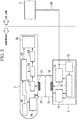
- FIG. 1 is a schematic structural view of a power transmission system A according to the present embodiment.
- the power transmission system A is provided with an underwater base station 1 (i.e., a power-transmitting device) that is installed in a predetermined underwater location, and an autonomous underwater vehicle 2 (i.e., a power-receiving device) that is able to move freely underwater by means of battery power, and with an electrical power system 3 that is installed on land.
- an underwater base station 1 i.e., a power-transmitting device
- an autonomous underwater vehicle 2 i.e., a power-receiving device
- the underwater base station 1 is connected via a power supply cable 100 to the on-land electrical power system 3, and wirelessly transmits (i.e., supplies) AC power (for example, 100 V single-phase power having a frequency of 50 or 60 Hz) that is supplied from the electrical power system 3 to the autonomous underwater vehicle 2 by means of magnetic field resonance.
- the underwater base station 1 is provided with an AC/AC converter 11, a power transmission resonance coil 12, a power transmission balloon 13, a power transmission balloon control mechanism 14, a power supply circuit 15, and a base station control device 16.
- the AC/AC converter 11 converts AC power that is supplied via the power supply cable100 from the on-land electrical power system 3 into AC power that has a predetermined voltage and a predetermined frequency that are suitable for a power transmission via magnetic field resonance.
- the AC/AC converter 11 outputs the converted AC power to the power transmission resonance coil 12.
- the power transmission resonance coil 12 is a spirally-wound helical coil that is used to transmit the AC power input from the AC/AC converter 11 wirelessly by means of magnetic field resonance.
- the power transmission resonance coil 12 is installed such that it protrudes above the underwater base station 1.
- An LC resonance circuit is formed by the power transmission resonance coil 12 and by a capacitor (not shown). Note that it is possible to use the parasitic capacity of the helical coil as the capacitor that is used to form the LC resonant circuit, or alternatively, it is also possible to provide a separate capacitor element. Moreover, it is also possible to provide a core that is formed from a material having high magnetic permeability such as ferrite inside the coil portion of the helical coil.
- the power transmission balloon 13 is provided on an external wall surface of the underwater base station 1 so as to house inside itself the power transmission resonance coil 12.
- the power transmission balloon 13 is able to inflate and deflate freely.
- FIG. 1 a state is shown in which the power transmission balloon 13 is deflated.
- the power transmission balloon control mechanism 14 inflates the power transmission balloon 13 during a power transmission, and deflates the power transmission balloon 13 during other times (i.e., times when power is not being transmitted). Specifically, the power transmission balloon control mechanism 14 causes the power transmission balloon 13 to be inflated by feeding gas to the interior of the power transmission balloon 13 via a gas tube 14a. In contrast, the power transmission balloon control mechanism 14 causes the power transmission balloon 13 to be deflated by suctioning gas from the interior of the power transmission balloon 13 via the gas tube 14a.
- side surfaces of the balloons prefferably be structured in the form of a bellows such that, when gas is being supplied to the interior of a balloon, the balloon inflates so as to fill the space between the power transmission coil and the power reception coil, but with only a small amount of inflation in the side surface direction of each coil.
- an inert gas such as nitrogen
- dry air may also be used.
- a non-corrosive organic material in liquid form, or water with a low content of ions or impurities (for example, water from which impurities have been removed by an ion-exchange resin).
- the power supply circuit 15 uses AC power that is supplied via the power supply cable 100 from the on-land electrical power system 3, and generates power supply voltage for use inside the underwater base station 1.
- the power supply circuit 15 outputs the generated power supply voltage to the base station control unit 16 and the power transmission balloon control mechanism 14.
- the base station control unit 16 is provided with a microprocessor and memory and the like, and, in accordance with control programs that have been stored in advance in its memory, controls the AC/AC converter 11 and the power transmission balloon control mechanism 14 during the transmission of power to the autonomous underwater vehicle 2.
- the autonomous underwater vehicle 2 collects data relating to water quality (hereinafter, this is expressed as 'water quality data') while traveling through the water by battery power, and when its battery is being recharged, receives AC power from the underwater base station 1 by means of magnetic field resonance.
- the autonomous underwater vehicle 2 is provided with a power reception resonance coil 21, a rectifier circuit 22, a charging circuit 23, a battery 24, a propulsion/steering mechanism 25, a water quality sensor 26, a power reception balloon 27, a power reception balloon control mechanism 28, and an autonomous vehicle control unit 29.
- the power reception resonance coil 21 is a spirally-wound helical coil that is used to receive AC power input from the power transmission resonance coil 12 of the underwater base station 1 wirelessly.
- the power reception resonance coil 21 is installed such that it protrudes below the autonomous underwater vehicle 2.
- An LC resonance circuit is formed by the power reception resonance coil 21 and by a capacitor (not shown). If the circuit constants of the LC resonance circuits of both the underwater base station 1 and the autonomous underwater vehicle 2 are set such that these resonance circuits are mutually equal, then it becomes possible to make magnetic field resonance occur between the power transmission resonance coil 12 and the power reception resonance coil 21.
- the rectifier circuit 22 rectifies the AC power received by the power reception resonance coil 21 so as to convert it into DC power, and then outputs this DC power to the charging circuit 23.
- the charging circuit 23 uses the DC power input by the rectifier circuit 22 to output to the battery 24 suitable voltage and current for charging the battery 24.
- the battery 24 is used as an internal power source by the autonomous underwater vehicle 2 and is a secondary cell such as, for example, a nickel hydrogen cell or a lithium ion cell, and outputs a power supply voltage (i.e., DC voltage) to the propulsion/steering mechanism 25.
- a power supply voltage i.e., DC voltage
- the battery 24 also supplies a power supply voltage to the water quality sensor 26, the power reception balloon control mechanism 28, and the autonomous vehicle control unit 29.
- the propulsion/steering mechanism 25 consists of a propeller and rudder, and of a drive mechanism (including a motor and motor driver and the like) that is used to drive these. Under the control of the autonomous vehicle control unit 29, the propulsion/steering mechanism 25 generates the propulsion force of the autonomous underwater vehicle 1 and also regulates the direction of travel thereof.
- the water quality sensor 26 detects the quality of seawater (for example, the water temperature, transparency, pH, nitrogen concentration, phosphorus concentration, and the like), and outputs these detection results as water quality data to the autonomous vehicle control unit 29.
- the power reception balloon 27 is provided on an external wall surface of the autonomous underwater vehicle 2 so as to house inside itself the power reception resonance coil 21.
- the power reception balloon 27 is able to inflate and deflate freely. It is desirable for the power reception balloon 27 to be formed from a resin (and particularly from rubber) such that it does not affect the magnetic field generated between the power transmission resonance coil 12 and the power reception resonance coil 21. Note that in FIG. 1 , a state is shown in which the power reception balloon 27 is completely deflated.
- components that are located between the coils are formed from graphite rubber, which has a high magnetic permeability, and it is desirable for components on the side that are not located between the coils to be formed from rubber that contains foil, powder or particles of a paramagnetic substance such as aluminum or copper that has a low magnetic permeability.
- the power reception balloon control mechanism 28 inflates the power reception balloon 27 during a power transmission, and deflates the power reception balloon 27 during other times (i.e., times when power is not being transmitted). Specifically, the power reception balloon control mechanism 28 causes the power reception balloon 27 to be inflated by feeding gas to the interior of the power reception balloon 27 via a gas tube 28a. In contrast, the power reception balloon control mechanism 28 causes the power reception balloon 27 to be deflated by suctioning gas from the interior of the power reception balloon 27 via the gas tube 28a.
- side surfaces of the balloons prefferably be structured in the form of a bellows such that, when gas is being supplied to the interior of a balloon, the balloon inflates so as to fill the space between the power transmission coil and the power reception coil, but with only a small amount of inflation in the side surface direction of each coil.
- the autonomous vehicle control unit 29 is provided with a microprocessor and memory and the like, and, in accordance with control programs that have been stored in advance in its memory, controls the propulsion/steering mechanism 25 and collects water quality data from the water quality sensor 26 (i.e., stores this water quality data in its memory).
- the autonomous vehicle control unit 29 controls the charging circuit 23 and the power reception balloon control mechanism 28.
- the autonomous vehicle control unit 29 of the autonomous underwater vehicle 2 controls the propulsion/steering mechanism 25 such that the autonomous underwater vehicle 2 travels through the water following a prescribed route. As a result of this, the autonomous underwater vehicle 2 travels through the water following a prescribed route. During this time, the autonomous vehicle control unit 29 acquires water quality data at a fixed time interval from the water quality sensor 26, and sequentially stores this acquired water quality data in its memory.
- the autonomous vehicle control unit 29 controls the power reception balloon control mechanism 28 such that the power reception balloon 27 is completely deflated.
- the base station control unit 16 of the underwater base station 1 stops the control of the AC/AC converter 11, and also controls the power transmission balloon control mechanism 14 such that the power transmission balloon 13 is completely deflated.
- the autonomous vehicle control unit 29 of the autonomous underwater vehicle 2 detects that the residual power of the battery 24 in the above-described normal mode has dropped below a specified value, it switches to charging mode in order to charge the battery 24.
- the autonomous vehicle control unit 29 switches to charging mode, it controls the propulsion/steering mechanism 25 such that the autonomous underwater vehicle 2 is made to move to a position above the underwater base station 1.
- the underwater base station 1 is located on the travel route of the autonomous underwater vehicle 2.
- the autonomous vehicle control unit 29 ascertains the position where the underwater base station 1 is installed from outputs from a position sensor (not shown) such as a sound wave sensor or optical sensor or the like.
- the autonomous vehicle control unit 29 of the autonomous underwater vehicle 2 When the autonomous vehicle control unit 29 of the autonomous underwater vehicle 2 has detected from the output from the position sensor in the form of a sound wave sensor or optical sensor or the like that the autonomous underwater vehicle 2 has moved to a position above the underwater base station 1, it controls the power reception balloon control mechanism 28 such that the power reception balloon 27 is completely inflated. Meanwhile, when the base station control unit 16 of the underwater base station 1 has detected from the output from the position sensor in the form of a sound wave sensor or optical sensor or the like that the autonomous underwater vehicle 2 has moved to a position above the underwater base station 1, it controls the power transmission balloon control mechanism 14 such that the power transmission balloon 13 is completely inflated.
- the base station control unit 16 of the underwater base station 1 controls the AC/AC converter 11 so as to cause AC power having a predetermined voltage and predetermined frequency that are suitable for transmitting power by means of magnetic field resonance to be output to the power transmission resonance coil 12.
- magnetic field resonance occurs between the power transmission resonance coil 12 of the underwater base station 1 and the power reception resonance coil 21 of the autonomous underwater vehicle 2.
- the AC power output from the AC/AC converter 11 is converted into magnetic energy by the power transmission resonance coil 12, and this magnetic energy is then transmitted wirelessly to the power reception resonance coil 21.
- the magnetic energy is then reconverted into AC power by the power reception resonance coil 21.
- the AC power that is received by the power reception resonance coil 21 is then converted into DC power by the rectifier circuit 22, which is located at a subsequent stage, and this DC power is then input into the charging circuit 23.
- the autonomous vehicle control unit 29 of the autonomous underwater vehicle 2 appropriately charges the battery 24 by controlling the charging circuit 23 while, at the same time, monitoring the state of charge of the battery 24.
- the autonomous vehicle control unit 29 controls the power reception balloon control mechanism 28 such that the power reception balloon 27 is fully deflated, and also controls the propulsion/steering mechanism 25 such that the autonomous underwater vehicle 2 collects water quality data while traveling along a prescribed route.
- the base station control unit 16 of the underwater base station 1 detects from a position sensor (not shown) such as a sound wave sensor or optical sensor or the like that the autonomous underwater vehicle 2 has moved, it stops its controlling of the AC/AC converter 11, and, at the same time, controls the power transmission balloon control mechanism 14 such that the power transmission balloon 13 is completely deflated.
- a position sensor not shown
- the base station control unit 16 of the underwater base station 1 detects from a position sensor (not shown) such as a sound wave sensor or optical sensor or the like that the autonomous underwater vehicle 2 has moved, it stops its controlling of the AC/AC converter 11, and, at the same time, controls the power transmission balloon control mechanism 14 such that the power transmission balloon 13 is completely deflated.
- a magnetic field resonance system is employed to transmit power underwater between the underwater base station 1 and the autonomous underwater vehicle 2.
- this magnetic field resonance system is more resistant to any positional shifting between the power transmission resonance coil 12 and the power reception resonance coil 21 (i.e., has a greater tolerance of any changes in their relative positions), and is able to transmit power using a weaker magnetic field and more efficiently and over a greater distance.
- a highly accurate positioning mechanism as is used in the conventional technology which employs electromagnetic induction is not required (in other words, a commonplace position sensor such as the aforementioned sound wave sensor or optical sensor or the like is sufficient).
- a commonplace position sensor such as the aforementioned sound wave sensor or optical sensor or the like is sufficient.
- the power transmission resonance coil 12 is covered by the power transmission balloon 13, and the power reception resonance coil 21 is covered by the power reception balloon 27.
- the efficiency of the power transmission between the power transmission resonance coil 12 and the power reception resonance coil 21 i.e., between the underwater base station 1 and the autonomous underwater vehicle 2 from deteriorating.
- the power transmission system of the present invention it is possible to achieve underwater power transmissions at low cost between a power-transmitting device and a power-receiving device. Moreover, it is possible to prevent the magnetic field being disturbed by the effects of ions and the like contained in the water, and it is thereby possible to prevent the efficiency of the power transmission between the power-transmitting device and the power-receiving device from deteriorating.
- a ... Power transmission system 1 ... Underwater base station (Power-transmitting device), 12 ... Power transmission resonance coil, 13 ... Power transmission balloon, 14 ... Power transmission balloon control mechanism, 2 ... Autonomous underwater vehicle (Power-receiving device), 21 ... Power reception resonance coil, 24 ... Battery, 27 ... Power reception balloon, 28 ... Power reception balloon control mechanism, 3 ... Electrical power system
Abstract
a resonance coil that performs power transmission wirelessly underwater by means of magnetic field resonance, and
a balloon that internally houses the resonance coil.
Description
- The present invention relates to a power transmission system. Priority is claimed on
Japanese Patent Application No. 2011-268250, filed December 7, 2011 - Conventionally, a method of examining the water quality of sea water using an autonomous underwater vehicle that travels through water by means of battery power is known. Naturally, if the residual battery power of the autonomous underwater vehicle drops to zero, it becomes impossible to collect data relating to the water quality or to travel through the water. Because of this, when the residual battery power drops below a specified value, it is normal for the autonomous underwater vehicle to be recovered to a surface vessel so that the battery can be charged.
- In this manner, if the autonomous underwater vehicle is recovered to the surface vessel each time the battery needs charging, then both the time required and the costs increase enormously. As a consequence, in recent years, advances have been made in the development of technology to enable this charging to be performed underwater. For example, in Patent document 1 (see below), technology is disclosed in which a battery that is installed in an underwater station that collects data relating to the water quality of sea water is charged by an underwater robot that travels through the water using a wireless power supply system (in particular, an electromagnetic induction system).
-
- [Patent document 1] Japanese Patent Application Laid-Open (
JP-A) No. 2004-166459 - [Patent document 2]
Japanese Patent No. 3493426 - [Patent document 3]
US Patent No. 8304935 - As in the aforementioned conventional technology, when an electromagnetic induction system is used as the wireless power supply system, in order to maximize the power transmission efficiency, it is necessary to accurately position the power-transmitting device (i.e., the underwater robot) and the power-receiving device (i.e., the underwater station) during the underwater power transmission (i.e., during the battery charging). Accordingly, it has been necessary to install a high-accuracy positioning mechanism for this purpose, so that the problem of high system costs has arisen.
- The present invention was conceived in view of the above-described circumstances and it is an object thereof to provide a power transmission system that makes it possible to achieve underwater power transmissions at low cost between a power-transmitting device and a power-receiving device of which at least one is capable of moving freely underwater.
- In order to achieve the above-described object, according to a first aspect of the present invention, in a power transmission system that transmits power underwater between a power-transmitting device and a power-receiving device of which at least one is capable of moving freely underwater, the power-transmitting device and the power-receiving device are each provided with a resonance coil that performs the power transmission wirelessly underwater by means of magnetic field resonance. At least one of the power-transmitting device and the power-receiving device is provided with a balloon that internally houses the resonance coil of its host device.
- Moreover, according to a second aspect of the present invention, in the above-described first aspect at least one of the power-transmitting device and the power-receiving device is provided with a balloon control mechanism that, during a power transmission, causes the balloon to inflate, and at other times, causes the balloon to be deflated.
- Moreover, according to a third aspect of the present invention, in the above-described first or second aspects the power-receiving device is an autonomous underwater vehicle that collects water quality data as it moves through the water under battery power. The power-transmitting device is an underwater base station that is installed in a predetermined location underwater and is connected by a cable to an on-land electrical power system, and receives from the electrical power system a supply of power that is to be transmitted to the autonomous underwater vehicle.
- Moreover, according to a fourth aspect of the present invention, in the above-described third aspect the autonomous underwater vehicle wirelessly transmits the water quality data to the underwater base station during a power transmission. The underwater base station is connected by cable to an on-land water quality data control device, and transmits the water quality data that it receives from the autonomous underwater vehicle by cable to the water quality data control device.
- In the present invention, a magnetic field resonance system is employed for underwater power transmissions between a power-transmitting device and a power-receiving device. Compared to an electromagnetic induction system, this magnetic field resonance system is largely unaffected by positional shifting of the resonance coils that are provided in both the power-transmitting device and the power-receiving device (i.e., is tolerant of positional shift), and is able to perform power transmissions highly efficiently and over long distances using only a weak magnetic field.
- Accordingly, according to the present invention, a high-accuracy positioning mechanism such as is used in the conventional technology which employs an electromagnetic induction system is rendered unnecessary. As a consequence, it is possible to achieve underwater power transmissions at low cost between a power-transmitting device and a power-receiving device. Moreover, in the present invention, at least one of the resonance coils of the power-transmitting device and the power-receiving device is covered by a balloon. As a result, it is possible to prevent the magnetic field being disrupted by the effects of ions and the like contained in the water, and to thereby prevent the power transmission efficiency between the power-transmitting device and the power-receiving device from deteriorating.
-
-
FIG. 1 is a schematic structural view of a power transmission system according to the present embodiment. -
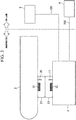
FIG. 2 is a view showing a state in which a power reception balloon of an autonomous underwater vehicle and a power transmission balloon of an underwater base station are inflated during the charging of a battery. -
FIG. 3 is a first explanatory view relating to a variant example of the present embodiment. -
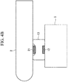
FIG. 4A is a second explanatory view relating to a variant example of the present embodiment. -
FIG. 4B is a third explanatory view relating to a variant example of the present embodiment. - Hereinafter, an embodiment of the present invention will be described with reference made to the drawings.
-
FIG. 1 is a schematic structural view of a power transmission system A according to the present embodiment. As is shown inFIG. 1 , the power transmission system A is provided with an underwater base station 1 (i.e., a power-transmitting device) that is installed in a predetermined underwater location, and an autonomous underwater vehicle 2 (i.e., a power-receiving device) that is able to move freely underwater by means of battery power, and with anelectrical power system 3 that is installed on land. - The
underwater base station 1 is connected via apower supply cable 100 to the on-landelectrical power system 3, and wirelessly transmits (i.e., supplies) AC power (for example, 100 V single-phase power having a frequency of 50 or 60 Hz) that is supplied from theelectrical power system 3 to the autonomousunderwater vehicle 2 by means of magnetic field resonance. Theunderwater base station 1 is provided with an AC/AC converter 11, a powertransmission resonance coil 12, apower transmission balloon 13, a power transmissionballoon control mechanism 14, apower supply circuit 15, and a basestation control device 16. - Under the control of the base
station control device 16, the AC/AC converter 11 converts AC power that is supplied via the power supply cable100 from the on-landelectrical power system 3 into AC power that has a predetermined voltage and a predetermined frequency that are suitable for a power transmission via magnetic field resonance. The AC/AC converter 11 outputs the converted AC power to the powertransmission resonance coil 12. - The power
transmission resonance coil 12 is a spirally-wound helical coil that is used to transmit the AC power input from the AC/AC converter 11 wirelessly by means of magnetic field resonance. The powertransmission resonance coil 12 is installed such that it protrudes above theunderwater base station 1. An LC resonance circuit is formed by the powertransmission resonance coil 12 and by a capacitor (not shown). Note that it is possible to use the parasitic capacity of the helical coil as the capacitor that is used to form the LC resonant circuit, or alternatively, it is also possible to provide a separate capacitor element. Moreover, it is also possible to provide a core that is formed from a material having high magnetic permeability such as ferrite inside the coil portion of the helical coil. - The
power transmission balloon 13 is provided on an external wall surface of theunderwater base station 1 so as to house inside itself the powertransmission resonance coil 12. Thepower transmission balloon 13 is able to inflate and deflate freely. It is desirable for thepower transmission balloon 13 to be formed from a resin (and particularly from rubber) such that it does not affect the magnetic field generated between the powertransmission resonance coil 12 and the powerreception resonance coil 21. It is particularly desirable for the balloon component that is placed between the coils to be formed from graphite rubber, which has a high magnetic permeability, and it is desirable for the balloon component on the side that is not located between the coils to be formed from rubber that contains foil, powder or particles of a paramagnetic substance such as aluminum or copper that has a low magnetic permeability. - Note that in
FIG. 1 , a state is shown in which thepower transmission balloon 13 is deflated. - Under the control of the base
station control unit 16, the power transmissionballoon control mechanism 14 inflates thepower transmission balloon 13 during a power transmission, and deflates thepower transmission balloon 13 during other times (i.e., times when power is not being transmitted). Specifically, the power transmissionballoon control mechanism 14 causes thepower transmission balloon 13 to be inflated by feeding gas to the interior of thepower transmission balloon 13 via agas tube 14a. In contrast, the power transmissionballoon control mechanism 14 causes thepower transmission balloon 13 to be deflated by suctioning gas from the interior of thepower transmission balloon 13 via thegas tube 14a. - In order to make the supply and removal of this gas more efficient, it is preferable for a plurality of the
gas tubes 14a to be provided. - By providing a partition inside the balloons so as to form a plurality of chambers, and then connecting a
gas tube 14a to each one of these chambers, and then supplying or removing the gas to the individual chambers via the power transmissionballoon control mechanism 14, it is possible to adjust the position and angle between the coils, and to also thereby control the position and angle between the coils relative to each other. - It is desirable for side surfaces of the balloons to be structured in the form of a bellows such that, when gas is being supplied to the interior of a balloon, the balloon inflates so as to fill the space between the power transmission coil and the power reception coil, but with only a small amount of inflation in the side surface direction of each coil.
- It is desirable for an inert gas such as nitrogen to be used for the gas, however, dry air may also be used.
- Moreover, instead of using gas, it is also possible to use a non-corrosive organic material in liquid form, or water with a low content of ions or impurities (for example, water from which impurities have been removed by an ion-exchange resin).
- The
power supply circuit 15 uses AC power that is supplied via thepower supply cable 100 from the on-landelectrical power system 3, and generates power supply voltage for use inside theunderwater base station 1. Thepower supply circuit 15 outputs the generated power supply voltage to the basestation control unit 16 and the power transmissionballoon control mechanism 14. The basestation control unit 16 is provided with a microprocessor and memory and the like, and, in accordance with control programs that have been stored in advance in its memory, controls the AC/AC converter 11 and the power transmissionballoon control mechanism 14 during the transmission of power to the autonomousunderwater vehicle 2. - The autonomous
underwater vehicle 2 collects data relating to water quality (hereinafter, this is expressed as 'water quality data') while traveling through the water by battery power, and when its battery is being recharged, receives AC power from theunderwater base station 1 by means of magnetic field resonance. The autonomousunderwater vehicle 2 is provided with a powerreception resonance coil 21, arectifier circuit 22, a chargingcircuit 23, abattery 24, a propulsion/steering mechanism 25, awater quality sensor 26, apower reception balloon 27, a power receptionballoon control mechanism 28, and an autonomousvehicle control unit 29. - The power
reception resonance coil 21 is a spirally-wound helical coil that is used to receive AC power input from the powertransmission resonance coil 12 of theunderwater base station 1 wirelessly. The powerreception resonance coil 21 is installed such that it protrudes below the autonomousunderwater vehicle 2. An LC resonance circuit is formed by the powerreception resonance coil 21 and by a capacitor (not shown). If the circuit constants of the LC resonance circuits of both theunderwater base station 1 and the autonomousunderwater vehicle 2 are set such that these resonance circuits are mutually equal, then it becomes possible to make magnetic field resonance occur between the powertransmission resonance coil 12 and the powerreception resonance coil 21. - The
rectifier circuit 22 rectifies the AC power received by the powerreception resonance coil 21 so as to convert it into DC power, and then outputs this DC power to the chargingcircuit 23. Under the control of the autonomousvehicle control unit 29, the chargingcircuit 23 uses the DC power input by therectifier circuit 22 to output to thebattery 24 suitable voltage and current for charging thebattery 24. - The
battery 24 is used as an internal power source by the autonomousunderwater vehicle 2 and is a secondary cell such as, for example, a nickel hydrogen cell or a lithium ion cell, and outputs a power supply voltage (i.e., DC voltage) to the propulsion/steering mechanism 25. Note that, although omitted fromFIG. 1 , thebattery 24 also supplies a power supply voltage to thewater quality sensor 26, the power receptionballoon control mechanism 28, and the autonomousvehicle control unit 29. Moreover, when necessary, it is also possible to provide a DC/DC converter that converts the output voltage from thebattery 24 to a desired value. - The propulsion/
steering mechanism 25 consists of a propeller and rudder, and of a drive mechanism (including a motor and motor driver and the like) that is used to drive these. Under the control of the autonomousvehicle control unit 29, the propulsion/steering mechanism 25 generates the propulsion force of the autonomousunderwater vehicle 1 and also regulates the direction of travel thereof. Thewater quality sensor 26 detects the quality of seawater (for example, the water temperature, transparency, pH, nitrogen concentration, phosphorus concentration, and the like), and outputs these detection results as water quality data to the autonomousvehicle control unit 29. - The
power reception balloon 27 is provided on an external wall surface of the autonomousunderwater vehicle 2 so as to house inside itself the powerreception resonance coil 21. Thepower reception balloon 27 is able to inflate and deflate freely. It is desirable for thepower reception balloon 27 to be formed from a resin (and particularly from rubber) such that it does not affect the magnetic field generated between the powertransmission resonance coil 12 and the powerreception resonance coil 21. Note that inFIG. 1 , a state is shown in which thepower reception balloon 27 is completely deflated. It is particularly desirable for components that are located between the coils to be formed from graphite rubber, which has a high magnetic permeability, and it is desirable for components on the side that are not located between the coils to be formed from rubber that contains foil, powder or particles of a paramagnetic substance such as aluminum or copper that has a low magnetic permeability. - Under the control of the autonomous
vehicle control unit 29, the power receptionballoon control mechanism 28 inflates thepower reception balloon 27 during a power transmission, and deflates thepower reception balloon 27 during other times (i.e., times when power is not being transmitted). Specifically, the power receptionballoon control mechanism 28 causes thepower reception balloon 27 to be inflated by feeding gas to the interior of thepower reception balloon 27 via agas tube 28a. In contrast, the power receptionballoon control mechanism 28 causes thepower reception balloon 27 to be deflated by suctioning gas from the interior of thepower reception balloon 27 via thegas tube 28a. - It is desirable for side surfaces of the balloons to be structured in the form of a bellows such that, when gas is being supplied to the interior of a balloon, the balloon inflates so as to fill the space between the power transmission coil and the power reception coil, but with only a small amount of inflation in the side surface direction of each coil.
- The autonomous
vehicle control unit 29 is provided with a microprocessor and memory and the like, and, in accordance with control programs that have been stored in advance in its memory, controls the propulsion/steering mechanism 25 and collects water quality data from the water quality sensor 26 (i.e., stores this water quality data in its memory). When thebattery 24 is being charged (i.e., when power is being transmitted from theunderwater base station 1 to the autonomous underwater vehicle 2), the autonomousvehicle control unit 29 controls the chargingcircuit 23 and the power receptionballoon control mechanism 28. - Next, operations of the power transmission system A according to the first embodiment that has the above-described structure will be described in detail.
- Firstly, a normal mode operation will be described. The autonomous
vehicle control unit 29 of the autonomousunderwater vehicle 2 controls the propulsion/steering mechanism 25 such that the autonomousunderwater vehicle 2 travels through the water following a prescribed route. As a result of this, the autonomousunderwater vehicle 2 travels through the water following a prescribed route. During this time, the autonomousvehicle control unit 29 acquires water quality data at a fixed time interval from thewater quality sensor 26, and sequentially stores this acquired water quality data in its memory. - In the above-described normal mode, if the power-
reception balloon 27 of the autonomousunderwater vehicle 2 is inflated, it obstructs the movement through the water of the autonomousunderwater vehicle 2. However, the autonomousvehicle control unit 29 controls the power receptionballoon control mechanism 28 such that thepower reception balloon 27 is completely deflated. In this normal mode, it is not necessary for power to be transmitted from theunderwater base station 1 to the autonomousunderwater vehicle 2. Because of this, the basestation control unit 16 of theunderwater base station 1 stops the control of the AC/AC converter 11, and also controls the power transmissionballoon control mechanism 14 such that thepower transmission balloon 13 is completely deflated. - When the autonomous
vehicle control unit 29 of the autonomousunderwater vehicle 2 detects that the residual power of thebattery 24 in the above-described normal mode has dropped below a specified value, it switches to charging mode in order to charge thebattery 24. When the autonomousvehicle control unit 29 switches to charging mode, it controls the propulsion/steering mechanism 25 such that the autonomousunderwater vehicle 2 is made to move to a position above theunderwater base station 1. Note that theunderwater base station 1 is located on the travel route of the autonomousunderwater vehicle 2. The autonomousvehicle control unit 29 ascertains the position where theunderwater base station 1 is installed from outputs from a position sensor (not shown) such as a sound wave sensor or optical sensor or the like. - When the autonomous
vehicle control unit 29 of the autonomousunderwater vehicle 2 has detected from the output from the position sensor in the form of a sound wave sensor or optical sensor or the like that the autonomousunderwater vehicle 2 has moved to a position above theunderwater base station 1, it controls the power receptionballoon control mechanism 28 such that thepower reception balloon 27 is completely inflated. Meanwhile, when the basestation control unit 16 of theunderwater base station 1 has detected from the output from the position sensor in the form of a sound wave sensor or optical sensor or the like that the autonomousunderwater vehicle 2 has moved to a position above theunderwater base station 1, it controls the power transmissionballoon control mechanism 14 such that thepower transmission balloon 13 is completely inflated. - As a result of this, as is shown in
FIG. 2 , thepower reception balloon 27 of the autonomousunderwater vehicle 2 and thepower transmission balloon 13 of theunderwater base station 1 are placed in contact with each other underwater. In this state, the basestation control unit 16 of theunderwater base station 1 controls the AC/AC converter 11 so as to cause AC power having a predetermined voltage and predetermined frequency that are suitable for transmitting power by means of magnetic field resonance to be output to the powertransmission resonance coil 12. - As a consequence, magnetic field resonance occurs between the power
transmission resonance coil 12 of theunderwater base station 1 and the powerreception resonance coil 21 of the autonomousunderwater vehicle 2. When this magnetic field resonance occurs, the AC power output from the AC/AC converter 11 is converted into magnetic energy by the powertransmission resonance coil 12, and this magnetic energy is then transmitted wirelessly to the powerreception resonance coil 21. The magnetic energy is then reconverted into AC power by the powerreception resonance coil 21. The AC power that is received by the powerreception resonance coil 21 is then converted into DC power by therectifier circuit 22, which is located at a subsequent stage, and this DC power is then input into the chargingcircuit 23. - The autonomous
vehicle control unit 29 of the autonomousunderwater vehicle 2 appropriately charges thebattery 24 by controlling the chargingcircuit 23 while, at the same time, monitoring the state of charge of thebattery 24. When the autonomousvehicle control unit 29 has detected that thebattery 24 has reached a fully charged state, it switches to the above-described normal mode. The autonomousvehicle control unit 29 controls the power receptionballoon control mechanism 28 such that thepower reception balloon 27 is fully deflated, and also controls the propulsion/steering mechanism 25 such that the autonomousunderwater vehicle 2 collects water quality data while traveling along a prescribed route. - When the base
station control unit 16 of theunderwater base station 1 detects from a position sensor (not shown) such as a sound wave sensor or optical sensor or the like that the autonomousunderwater vehicle 2 has moved, it stops its controlling of the AC/AC converter 11, and, at the same time, controls the power transmissionballoon control mechanism 14 such that thepower transmission balloon 13 is completely deflated. - As is described above, in the present embodiment, a magnetic field resonance system is employed to transmit power underwater between the
underwater base station 1 and the autonomousunderwater vehicle 2. Compared to an electromagnetic induction system, this magnetic field resonance system is more resistant to any positional shifting between the powertransmission resonance coil 12 and the power reception resonance coil 21 (i.e., has a greater tolerance of any changes in their relative positions), and is able to transmit power using a weaker magnetic field and more efficiently and over a greater distance. - Accordingly, according to the present embodiment, a highly accurate positioning mechanism as is used in the conventional technology which employs electromagnetic induction is not required (in other words, a commonplace position sensor such as the aforementioned sound wave sensor or optical sensor or the like is sufficient). As a result of this, it is possible for power to be transmitted underwater between the
underwater base station 1 and the autonomousunderwater vehicle 2 at a low cost. - Moreover, in the present embodiment, the power
transmission resonance coil 12 is covered by thepower transmission balloon 13, and the powerreception resonance coil 21 is covered by thepower reception balloon 27. As a result of this, it is possible to prevent the magnetic field being disturbed by the effects of ions and the like contained in the seawater, and it is thereby possible to prevent the efficiency of the power transmission between the powertransmission resonance coil 12 and the power reception resonance coil 21 (i.e., between theunderwater base station 1 and the autonomous underwater vehicle 2) from deteriorating. - Note that the present invention is not limited to the above-described embodiment, and variant examples such as those described below are also possible.
- (1) In the above-described embodiment, in order to extract the water quality data saved in the autonomous
underwater vehicle 2 to the outside, it is necessary to recover the autonomousunderwater vehicle 2 to a surface vessel or the like. In contrast to this, as is shown, for example, inFIG. 3 , it is possible to employ a system structure in which theunderwater base station 1 is connected by means of acommunication cable 200 to an on-land water qualitydata control device 4, and during a power transmission (i.e., when thebattery 24 is being charged) the autonomousunderwater vehicle 2 transmits water quality data wirelessly via anantenna 30 to theunderwater base station 1, and theunderwater base station 1 transmits the water quality data received via theantenna 17 from the autonomousunderwater vehicle 2 to the water qualitydata control device 4 by means of a cable.
In the system structure shown inFIG. 3 , it is assumed that water quality data is communicated wirelessly via radio waves. Because of this, it is necessary for theantenna 30 to be covered by thepower reception balloon 27 and for theantenna 17 to be covered by thepower transmission balloon 13. However, if sound wave communication, optical communication, or infrared communication or the like is used for the wireless communication of the water quality data, then it is not necessary to provide theantennas - (2) In the above-described embodiment, a case is described in which balloons (i.e., the
power transmission balloon 13 and the power reception balloon 27) that internally contain resonance coils (i.e., the powertransmission resonance coil 12 and the power reception resonance coil 21) are provided in both theunderwater base station 1 and the autonomousunderwater vehicle 2. However, the present invention is not limited to this and it is also possible to provide a balloon that internally houses a resonance coil in only one of theunderwater base station 1 and the autonomousunderwater vehicle 2.FIG. 4A shows an example of a case in which thepower reception balloon 27 that internally contains the powerreception resonance coil 21 is only provided in the autonomousunderwater vehicle 2.FIG. 4B shows an example of a case in which thepower transmission balloon 13 that internally contains the powertransmission resonance coil 12 is only provided in theunderwater base station 1. It is also possible to provide a plurality of power transmission coils, or to separately prepare those balloons having no power transmission function, arranged side-by-side in parallel to the autonomous underwater vehicle, which will prevent the autonomousunderwater vehicle 2 being damaged by direct contact with theunderwater base station 1 or with a jetty.
In the above description, the powertransmission resonance coil 12 and the powerreception resonance coil 21 both have protruding structures, however, it is also possible to employ a structure in which these are built into theunderwater base station 1 and the autonomousunderwater vehicle 2 respectively, and an aperture portion is provided in each one that emits electromagnetic waves to the outside and is covered by thepower transmission balloon 13 and thepower reception balloon 27 respectively.
In this case, when thepower reception balloon 27 is being inflated, it is possible to utilize a 'jamming transition' phenomenon in order to cover the powertransmission resonance coil 12 and fix it in position by means of thepower reception balloon 27. Namely, thepower reception balloon 27 is filled in advance with a powder or granulated material. After thepower reception balloon 27 has been inflated such that it covers the powertransmission resonance coil 12, then the gas inside thepower reception balloon 27 is suctioned out. As a result of this, the interior of the balloon is fixed in place by the friction of the powder or granulated material, and it is possible to firmly fix the powertransmission resonance coil 12 in position by means of thepower reception balloon 27. Conversely, when thepower transmission balloon 13 is being inflated, it is possible to use the 'jamming transition' phenomenon in order to cover the powersupply resonance coil 21 and fix it in position by means of thepower transmission balloon 13. Namely, thepower reception balloon 13 is filled in advance with a powder or granulated material. After thepower reception balloon 13 has been inflated such that it covers the powertransmission resonance coil 21, the gas inside thepower reception balloon 13 is suctioned out. As a result of this, the interior of the balloon is fixed in place by the friction of the powder or granulated material, and it is possible to firmly fix the powerreception resonance coil 21 in place by means of thepower transmission balloon 13. Note that the powder or granulated material may be formed from a material having a high level of magnetic permeability, or from a ceramic material that does not obstruct the wireless supply of power (for example, alumina, mullite, ferrite, forsterite, zirconia, zircon, cordierite, aluminum nitride, silicon nitride, silicon carbide, lead zirconate titanate, and conjugated compounds of these), and compounds of these with resins containing a high polymer material.
If a structure is employed in which the powertransmission resonance coil 12 and thepower reception coil 21 are built into theunderwater base station 1 and the autonomousunderwater vehicle 2 respectively, and an aperture portion is provided in each one that emits electromagnetic waves to the outside and is covered by thepower transmission balloon 13 and thepower reception balloon 27 respectively, then it is possible to introduce the powder or granulated material at the same time as the gas or fluid is introduced into the interior of each balloon such that the balloon portions become intertwined with each other, and to then discharge only the gas or fluid at mutually offset times in each balloon. - (3) In the above-described embodiment, a case is described in which the power-transmitting device (i.e., the underwater base station 1) is fixed underwater, and the power-receiving device (i.e., the autonomous underwater vehicle 2) is able to move through the water. However, the present invention is not limited to this and it is also possible for this relationship to be reversed. Alternatively, it is also possible to employ a system structure in which both the power-transmitting device and the power-receiving device are able to move freely through the water. The present invention is also not limited to sea water, and can also be applied broadly to the transmission of power in any water such as lakes, rivers, and swamps and the like.
- (4) The power
transmission resonance coil 12 and the powerreception resonance coil 21 are not limited to being helical coils. Provided that the transmission of power is possible wirelessly by means of magnetic field resonance between the powertransmission resonance coil 12 and the powerreception resonance coil 21, then a coil of any desired shape and configuration such as solenoid or the like may be used. Moreover, the shape, configuration, and size of the two coils does not need to be the same. - According to the power transmission system of the present invention, it is possible to achieve underwater power transmissions at low cost between a power-transmitting device and a power-receiving device. Moreover, it is possible to prevent the magnetic field being disturbed by the effects of ions and the like contained in the water, and it is thereby possible to prevent the efficiency of the power transmission between the power-transmitting device and the power-receiving device from deteriorating.
- While preferred embodiments of the invention have been described and illustrated above, it should be understood that these are exemplary of the invention and are not to be considered as limiting. Additions, omissions, substitutions, and other modifications can be made without departing from the spirit or scope of the present invention. Accordingly, the invention is not to be considered as limited by the foregoing description and is only limited by the scope of the appended claims.
- A ... Power transmission system, 1 ... Underwater base station (Power-transmitting device), 12 ... Power transmission resonance coil, 13 ... Power transmission balloon, 14 ... Power transmission balloon control mechanism, 2 ... Autonomous underwater vehicle (Power-receiving device), 21 ... Power reception resonance coil, 24 ... Battery, 27 ... Power reception balloon, 28 ... Power reception balloon control mechanism, 3 ... Electrical power system
- Aspects of the invention will now be summarized in the following clauses:
- 1. A power transmission system that transmits power underwater between a power-transmitting device and a power-receiving device of which at least one is capable of moving freely underwater, wherein
the power-transmitting device and the power-receiving device are each provided with a resonance coil that performs the power transmission wirelessly underwater by means of magnetic field resonance, and
at least one of the power-transmitting device and the power-receiving device is provided with a balloon that internally houses the resonance coil of its own device. - 2. The power transmission system according to
clause 1, wherein at least one of the power-transmitting device and the power-receiving device is provided with a balloon control mechanism that, during a power transmission, causes the balloon to inflate, and at other times, causes the balloon to be deflated. - 3. The power transmission system according to
clause
the power-receiving device is an autonomous underwater vehicle that collects water quality data as it moves through the water under battery power, and
the power-transmitting device is an underwater base station that is installed in a predetermined location underwater and is connected by a cable to an on-land electrical power system, and receives from the electrical power system a supply of power that is to be transmitted to the autonomous underwater vehicle. - 4. The power transmission system according to
clause 3, wherein
the autonomous underwater vehicle wirelessly transmits the water quality data to the underwater base station during a power transmission, and
the underwater base station is connected by cable to an on-land water quality data control device, and transmits the water quality data that it receives from the autonomous underwater vehicle by cable to the water quality data control device.
Claims (8)
- A power-transmitting device comprising:a resonance coil that performs power transmission wirelessly underwater by means of magnetic field resonance, anda balloon that internally houses the resonance coil.
- The power-transmitting device according to claim 1, further comprising a balloon control mechanism that, during a power transmission, causes the balloon to inflate, and at other times, causes the balloon to be deflated.
- The power-transmitting device according to claim 1 or 2, wherein
the power-transmitting device is an underwater base station that is installed in a predetermined location underwater and is connected by a cable to an on-land electrical power system, and receives from the electrical power system a supply of power that is to be transmitted. - The power-transmitting device according to claim 3, wherein
the underwater base station is connected by cable to an on-land water quality data control device, and transmits the water quality data that it receives from an antenna by cable to the water quality data control device. - A power-receiving device comprising:a resonance coil that receives power wirelessly underwater by means of magnetic field resonance, anda balloon that internally houses the resonance coil.
- The power-receiving device according to claim 5, further comprising a balloon control mechanism that, during power-receiving, causes the balloon to inflate, and at other times, causes the balloon to be deflated.
- The power-receiving device according to claim 5 or 6, wherein
the power-receiving device is an autonomous underwater vehicle that collects water quality data as it moves through the water under battery power. - The power-receiving device according to claim 7, wherein
the autonomous underwater vehicle transmits the water quality data via an antenna during a power transmission.
Applications Claiming Priority (2)
| Application Number | Priority Date | Filing Date | Title |
|---|---|---|---|
| JP2011268250 | 2011-12-07 | ||
| EP12856483.8A EP2790294B1 (en) | 2011-12-07 | 2012-12-07 | Power transmission system |
Related Parent Applications (2)
| Application Number | Title | Priority Date | Filing Date |
|---|---|---|---|
| EP12856483.8A Division-Into EP2790294B1 (en) | 2011-12-07 | 2012-12-07 | Power transmission system |
| EP12856483.8A Division EP2790294B1 (en) | 2011-12-07 | 2012-12-07 | Power transmission system |
Publications (2)
| Publication Number | Publication Date |
|---|---|
| EP3076517A1 true EP3076517A1 (en) | 2016-10-05 |
| EP3076517B1 EP3076517B1 (en) | 2017-07-26 |
Family
ID=48574383
Family Applications (2)
| Application Number | Title | Priority Date | Filing Date |
|---|---|---|---|
| EP12856483.8A Active EP2790294B1 (en) | 2011-12-07 | 2012-12-07 | Power transmission system |
| EP16158312.5A Active EP3076517B1 (en) | 2011-12-07 | 2012-12-07 | Power transmission system |
Family Applications Before (1)
| Application Number | Title | Priority Date | Filing Date |
|---|---|---|---|
| EP12856483.8A Active EP2790294B1 (en) | 2011-12-07 | 2012-12-07 | Power transmission system |
Country Status (5)
| Country | Link |
|---|---|
| US (1) | US9577462B2 (en) |
| EP (2) | EP2790294B1 (en) |
| JP (2) | JP5637319B2 (en) |
| CN (2) | CN105966578B (en) |
| WO (1) | WO2013085030A1 (en) |
Families Citing this family (45)
| Publication number | Priority date | Publication date | Assignee | Title |
|---|---|---|---|---|
| US9327608B2 (en) * | 2011-08-04 | 2016-05-03 | Schneider Electric USA, Inc. | Extendable and deformable carrier for a primary coil of a charging system |
| EP2814047B1 (en) * | 2012-02-06 | 2021-08-04 | IHI Corporation | Non-contact power supply system |
| JP6111583B2 (en) * | 2012-10-01 | 2017-04-12 | 株式会社Ihi | Contactless power supply system |
| EP3025411B1 (en) | 2013-07-12 | 2018-09-26 | Schneider Electric USA, Inc. | Method and device for foreign object detection in induction electric charger |
| JP6376732B2 (en) * | 2013-07-18 | 2018-08-22 | Ihi運搬機械株式会社 | Contactless power supply system |
| GB2521626C (en) | 2013-12-23 | 2019-10-30 | Subsea 7 Ltd | Transmission of power underwater |
| EP3101778B1 (en) | 2014-01-29 | 2020-02-19 | Nec Corporation | Wireless power transmission control device, wireless power transmission system, and wireless power transmission control method |
| WO2015129247A1 (en) * | 2014-02-25 | 2015-09-03 | 日本電気株式会社 | Wireless power-feeding device, wireless power-feeding system, and wireless power-feeding method |
| WO2015186697A1 (en) | 2014-06-06 | 2015-12-10 | 株式会社Ihi | Power transmitting device, power receiving device, and wireless power supply system |
| FR3022411B1 (en) * | 2014-06-13 | 2016-07-15 | Dcns | SUBMARINE ENGINE HAVING ENERGY STORAGE SOURCES BASED ON LITHIUM-ION BATTERIES |
| US10608479B2 (en) | 2015-01-23 | 2020-03-31 | Battelle Memorial Institute | Underwater power and data transfer system |
| WO2016121089A1 (en) * | 2015-01-30 | 2016-08-04 | 中国電力株式会社 | Power supply system and power supply method |
| US9829599B2 (en) | 2015-03-23 | 2017-11-28 | Schneider Electric USA, Inc. | Sensor and method for foreign object detection in induction electric charger |
| JP6531942B2 (en) | 2015-07-21 | 2019-06-19 | パナソニックIpマネジメント株式会社 | Power transmission device |
| JP6581874B2 (en) * | 2015-10-06 | 2019-09-25 | 川崎重工業株式会社 | Autonomous unmanned submersible charging system |
| CN105826983A (en) * | 2016-05-12 | 2016-08-03 | 大连理工大学 | Power supply system for underwater apparatus |
| JP6737648B2 (en) * | 2016-06-30 | 2020-08-12 | パナソニック株式会社 | Power transmission equipment |
| US10392086B2 (en) * | 2016-08-26 | 2019-08-27 | Saudi Arabian Oil Company | Wirelessly controlled subsystems for underwater remotely operated vehicles |
| JP6848320B2 (en) * | 2016-10-06 | 2021-03-24 | 富士ゼロックス株式会社 | Underwater mobile |
| JP6927688B2 (en) | 2016-10-28 | 2021-09-01 | パナソニック株式会社 | Power transmission system |
| JP6292364B1 (en) * | 2017-03-01 | 2018-03-14 | 中国電力株式会社 | Non-contact power supply system, power transmission equipment, and power receiving equipment |
| FR3064246B1 (en) * | 2017-03-23 | 2023-11-10 | Dcns | IMMERSED SYSTEM FOR STORING AND MAINTAINING AN UNDERWATER VEHICLE SUCH AS A DRONE IN OPERATIONAL CONDITION |
| US10675982B2 (en) | 2017-03-27 | 2020-06-09 | General Electric Company | System and method for inductive charging with improved efficiency |
| JP6568133B2 (en) | 2017-03-30 | 2019-08-28 | パナソニック株式会社 | Transmission coil and power transmission device |
| JP6594373B2 (en) * | 2017-05-10 | 2019-10-23 | パナソニック株式会社 | Power transmission equipment |
| US10807692B2 (en) | 2017-05-26 | 2020-10-20 | Lynntech, Inc. | Undersea vehicle and method for operating the same |
| US10543893B2 (en) * | 2017-05-26 | 2020-01-28 | Lynntech, Inc. | Undersea vehicle and method for operating a reactor |
| US10916785B2 (en) | 2017-05-26 | 2021-02-09 | Lynntech, Inc. | Fuel cell storage system |
| US10622845B2 (en) * | 2017-12-05 | 2020-04-14 | Searete Llc | Non-Gaussian beamforming for wireless power transfer optimization |
| CN107769345A (en) * | 2017-12-08 | 2018-03-06 | 武汉理工大学 | A kind of electric yacht wireless charging device |
| US11128183B2 (en) | 2018-03-27 | 2021-09-21 | Panasonic Corporation | Electric power transmission device |
| JP7069939B2 (en) * | 2018-03-28 | 2022-05-18 | 日本電気株式会社 | Mobile objects, charging systems, control methods and programs |
| JP7148266B2 (en) * | 2018-04-26 | 2022-10-05 | 川崎重工業株式会社 | Work method using autonomous unmanned submersible |
| CN108820171A (en) * | 2018-05-23 | 2018-11-16 | 山东交通学院 | A kind of underwater networking using renewable energy continues observation system and its method |
| JP7117540B2 (en) | 2018-07-31 | 2022-08-15 | パナソニックIpマネジメント株式会社 | Power receiving device and underwater power supply system |
| KR102097682B1 (en) * | 2018-10-16 | 2020-04-06 | 국방과학연구소 | Undersea power system and operation method thereof |
| CN117162818A (en) * | 2018-10-17 | 2023-12-05 | 合芯磁导科技(无锡)有限公司 | Telescopic safety guard rail for wireless charging transmitter of electric automobile |
| WO2020130849A1 (en) * | 2018-12-19 | 2020-06-25 | Blue Logic As | System for docking a submarine vessel to a docking port and a method for docking the submarine vessel on the docking port |
| JP7263954B2 (en) * | 2019-07-12 | 2023-04-25 | 株式会社Ihi | power supply system |
| JP7302381B2 (en) * | 2019-08-26 | 2023-07-04 | 株式会社Ihi | Coil device |
| NL2024690B1 (en) * | 2020-01-17 | 2021-09-08 | Fnv Ip Bv | Underwater vehicle docking and communication |
| JP2022086557A (en) | 2020-11-30 | 2022-06-09 | パナソニックホールディングス株式会社 | Power receiving device, transmission voltage control method, and underwater power supply system |
| CN112477643B (en) * | 2020-12-10 | 2022-08-19 | 重庆凝光科技有限公司 | Underwater charging device |
| EP4214082A1 (en) * | 2021-01-11 | 2023-07-26 | Kamil PODHOLA | Offshore wireless power transfer system |
| US20230064567A1 (en) * | 2021-09-01 | 2023-03-02 | X Development Llc | Autonomous seagoing power replenishment watercraft |
Citations (3)
| Publication number | Priority date | Publication date | Assignee | Title |
|---|---|---|---|---|
| JP3493426B2 (en) | 2000-01-17 | 2004-02-03 | 独立行政法人通信総合研究所 | Balloon antenna |
| JP2004166459A (en) | 2002-11-15 | 2004-06-10 | Mitsui Eng & Shipbuild Co Ltd | Non-contact feeding device |
| US20110043047A1 (en) * | 2008-09-27 | 2011-02-24 | Aristeidis Karalis | Wireless energy transfer using field shaping to reduce loss |
Family Cites Families (15)
| Publication number | Priority date | Publication date | Assignee | Title |
|---|---|---|---|---|
| JPS62122435A (en) | 1985-11-22 | 1987-06-03 | Oki Electric Ind Co Ltd | Network access system |
| JPS62122435U (en) * | 1986-01-23 | 1987-08-04 | ||
| JPH0799910B2 (en) * | 1988-07-20 | 1995-10-25 | 三井造船株式会社 | Remote underwater power supply device |
| CN1802123B (en) * | 2002-05-16 | 2010-04-28 | 梅德拉股份有限公司 | System of obtaining images and spectra of intracavity structures using 3.0 tesla magnetic resonance systems |
| DE102005000761B4 (en) * | 2005-01-04 | 2008-05-21 | Siemens Ag | Intracorporeal endolocular coil for recording magnetic resonance signals |
| CN2887748Y (en) * | 2006-04-29 | 2007-04-11 | 中国科学院沈阳自动化研究所 | Underwater robot for underwater monitoring platform |
| CN101197507A (en) * | 2006-12-06 | 2008-06-11 | 北京中电华大电子设计有限责任公司 | Wireless power device and circuit |
| US8212414B2 (en) * | 2008-07-10 | 2012-07-03 | Lockheed Martin Corporation | Resonant, contactless radio frequency power coupling |
| US8324759B2 (en) * | 2008-09-27 | 2012-12-04 | Witricity Corporation | Wireless energy transfer using magnetic materials to shape field and reduce loss |
| JP4478729B1 (en) * | 2008-12-24 | 2010-06-09 | 株式会社豊田自動織機 | Resonant non-contact charging device |
| JP5016069B2 (en) * | 2010-01-12 | 2012-09-05 | トヨタ自動車株式会社 | Power transmission system and vehicle power supply device |
| JP2011234605A (en) * | 2010-04-05 | 2011-11-17 | Tdk Corp | Wireless power reception device and wireless power transmission system |
| US8968609B2 (en) * | 2010-05-12 | 2015-03-03 | General Electric Company | Dielectric materials for power transfer system |
| CN201928065U (en) * | 2011-01-04 | 2011-08-10 | 深圳市航嘉驰源电气股份有限公司 | Wireless charger |
| BR112013021317B1 (en) * | 2011-02-21 | 2022-06-21 | Wisub As | Underwater connector arrangement, and method of transferring data between a first underwater component and a second underwater component of a connector arrangement |
-
2012
- 2012-12-07 EP EP12856483.8A patent/EP2790294B1/en active Active
- 2012-12-07 CN CN201610359374.1A patent/CN105966578B/en active Active
- 2012-12-07 JP JP2013548313A patent/JP5637319B2/en active Active
- 2012-12-07 CN CN201280059930.3A patent/CN103959603B/en active Active
- 2012-12-07 WO PCT/JP2012/081781 patent/WO2013085030A1/en unknown
- 2012-12-07 EP EP16158312.5A patent/EP3076517B1/en active Active
-
2014
- 2014-05-01 US US14/266,911 patent/US9577462B2/en active Active
- 2014-10-23 JP JP2014216455A patent/JP5807712B2/en active Active
Patent Citations (4)
| Publication number | Priority date | Publication date | Assignee | Title |
|---|---|---|---|---|
| JP3493426B2 (en) | 2000-01-17 | 2004-02-03 | 独立行政法人通信総合研究所 | Balloon antenna |
| JP2004166459A (en) | 2002-11-15 | 2004-06-10 | Mitsui Eng & Shipbuild Co Ltd | Non-contact feeding device |
| US20110043047A1 (en) * | 2008-09-27 | 2011-02-24 | Aristeidis Karalis | Wireless energy transfer using field shaping to reduce loss |
| US8304935B2 (en) | 2008-09-27 | 2012-11-06 | Witricity Corporation | Wireless energy transfer using field shaping to reduce loss |
Non-Patent Citations (3)
| Title |
|---|
| KOJIYA T ET AL: "Automatic power supply system to underwater vehicles utilizing noncontacting technology", OCEANS '04. MTTS/IEEE TECHNO-OCEAN '04 KOBE, JAPAN NOV. 9-12, 2004, PISCATAWAY, NJ, USA,IEEE, vol. 4, 9 November 2004 (2004-11-09), pages 2341 - 2345, XP010776789, ISBN: 978-0-7803-8669-3, DOI: 10.1109/OCEANS.2004.1406521 * |
| MCGINNIS T ET AL: "Inductive Power System for Autonomous Underwater Vehicles", OCEANS 2007, IEEE, PISCATAWAY, NJ, USA, 29 September 2007 (2007-09-29), pages 1 - 5, XP031229062 * |
| ZE-SONG LI ET AL: "Design considerations for electromagnetic couplers in contactless power transmission systems for deep-sea applications", JOURNAL OF ZHEJIANG UNIVERSITY SCIENCE C. COMPUTERS & ELECTRONICS ZHEJIANG UNIVERSITY PRESS CHINA, vol. 11, no. 10, October 2010 (2010-10-01), pages 824 - 834, XP002741738, ISSN: 1869-1951 * |
Also Published As
| Publication number | Publication date |
|---|---|
| US20140232200A1 (en) | 2014-08-21 |
| EP2790294A1 (en) | 2014-10-15 |
| CN103959603B (en) | 2016-07-06 |
| EP2790294B1 (en) | 2016-05-11 |
| CN105966578A (en) | 2016-09-28 |
| JPWO2013085030A1 (en) | 2015-04-27 |
| CN103959603A (en) | 2014-07-30 |
| CN105966578B (en) | 2018-04-06 |
| EP2790294A4 (en) | 2015-08-19 |
| EP3076517B1 (en) | 2017-07-26 |
| US9577462B2 (en) | 2017-02-21 |
| JP5637319B2 (en) | 2014-12-10 |
| JP5807712B2 (en) | 2015-11-10 |
| WO2013085030A1 (en) | 2013-06-13 |
| JP2015015901A (en) | 2015-01-22 |
Similar Documents
| Publication | Publication Date | Title |
|---|---|---|
| US9577462B2 (en) | Power transmission system | |
| US9564759B2 (en) | Wireless power supply system | |
| US10263478B2 (en) | Wireless power supply system | |
| US9362783B2 (en) | Wireless power transmission apparatus using ultrasound | |
| US11031820B2 (en) | Power transmitting device | |
| US10608479B2 (en) | Underwater power and data transfer system | |
| EP2814047A1 (en) | Non-contact power supply system | |
| US10862341B2 (en) | Electric power transmission device | |
| JP2015231307A (en) | Power transmission device, power reception device and non-contact power supply system | |
| JP6112260B2 (en) | Power supply system and power supply method | |
| JP6643139B2 (en) | Non-contact power supply device for underwater robots | |
| JP2020022267A (en) | Power reception device, power transmission device, and underwater power supply system | |
| JP2021114833A (en) | Underwater non-contact power supply device | |
| KR102437144B1 (en) | electrical energy transfer device | |
| Hasaba et al. | Experimental Study of kW-class Wireless Charging System for Autonomous Underwater Vehicle with Magnetic Resonance | |
| JP2018078773A (en) | Wireless power supply device and wireless power supply method | |
| JP6146124B2 (en) | Non-contact power supply system and system | |
| JP6146116B2 (en) | Non-contact power supply system and bag system |
Legal Events
| Date | Code | Title | Description |
|---|---|---|---|
| PUAI | Public reference made under article 153(3) epc to a published international application that has entered the european phase |
Free format text: ORIGINAL CODE: 0009012 |
|
| 17P | Request for examination filed |
Effective date: 20160302 |
|
| AC | Divisional application: reference to earlier application |
Ref document number: 2790294 Country of ref document: EP Kind code of ref document: P |
|
| AK | Designated contracting states |
Kind code of ref document: A1 Designated state(s): AL AT BE BG CH CY CZ DE DK EE ES FI FR GB GR HR HU IE IS IT LI LT LU LV MC MK MT NL NO PL PT RO RS SE SI SK SM TR |
|
| GRAP | Despatch of communication of intention to grant a patent |
Free format text: ORIGINAL CODE: EPIDOSNIGR1 |
|
| RIC1 | Information provided on ipc code assigned before grant |
Ipc: H02J 7/00 20060101AFI20170112BHEP |
|
| INTG | Intention to grant announced |
Effective date: 20170210 |
|
| GRAS | Grant fee paid |
Free format text: ORIGINAL CODE: EPIDOSNIGR3 |
|
| GRAA | (expected) grant |
Free format text: ORIGINAL CODE: 0009210 |
|
| AC | Divisional application: reference to earlier application |
Ref document number: 2790294 Country of ref document: EP Kind code of ref document: P |
|
| AK | Designated contracting states |
Kind code of ref document: B1 Designated state(s): AL AT BE BG CH CY CZ DE DK EE ES FI FR GB GR HR HU IE IS IT LI LT LU LV MC MK MT NL NO PL PT RO RS SE SI SK SM TR |
|
| REG | Reference to a national code |
Ref country code: GB Ref legal event code: FG4D |
|
| REG | Reference to a national code |
Ref country code: CH Ref legal event code: EP |
|
| REG | Reference to a national code |
Ref country code: AT Ref legal event code: REF Ref document number: 913143 Country of ref document: AT Kind code of ref document: T Effective date: 20170815 |
|
| REG | Reference to a national code |
Ref country code: IE Ref legal event code: FG4D |
|
| REG | Reference to a national code |
Ref country code: DE Ref legal event code: R096 Ref document number: 602012035195 Country of ref document: DE |
|
| REG | Reference to a national code |
Ref country code: NL Ref legal event code: MP Effective date: 20170726 |
|
| REG | Reference to a national code |
Ref country code: LT Ref legal event code: MG4D |
|
| REG | Reference to a national code |
Ref country code: AT Ref legal event code: MK05 Ref document number: 913143 Country of ref document: AT Kind code of ref document: T Effective date: 20170726 |
|
| PG25 | Lapsed in a contracting state [announced via postgrant information from national office to epo] |
Ref country code: NO Free format text: LAPSE BECAUSE OF FAILURE TO SUBMIT A TRANSLATION OF THE DESCRIPTION OR TO PAY THE FEE WITHIN THE PRESCRIBED TIME-LIMIT Effective date: 20171026 Ref country code: LT Free format text: LAPSE BECAUSE OF FAILURE TO SUBMIT A TRANSLATION OF THE DESCRIPTION OR TO PAY THE FEE WITHIN THE PRESCRIBED TIME-LIMIT Effective date: 20170726 Ref country code: AT Free format text: LAPSE BECAUSE OF FAILURE TO SUBMIT A TRANSLATION OF THE DESCRIPTION OR TO PAY THE FEE WITHIN THE PRESCRIBED TIME-LIMIT Effective date: 20170726 Ref country code: HR Free format text: LAPSE BECAUSE OF FAILURE TO SUBMIT A TRANSLATION OF THE DESCRIPTION OR TO PAY THE FEE WITHIN THE PRESCRIBED TIME-LIMIT Effective date: 20170726 Ref country code: NL Free format text: LAPSE BECAUSE OF FAILURE TO SUBMIT A TRANSLATION OF THE DESCRIPTION OR TO PAY THE FEE WITHIN THE PRESCRIBED TIME-LIMIT Effective date: 20170726 Ref country code: SE Free format text: LAPSE BECAUSE OF FAILURE TO SUBMIT A TRANSLATION OF THE DESCRIPTION OR TO PAY THE FEE WITHIN THE PRESCRIBED TIME-LIMIT Effective date: 20170726 Ref country code: FI Free format text: LAPSE BECAUSE OF FAILURE TO SUBMIT A TRANSLATION OF THE DESCRIPTION OR TO PAY THE FEE WITHIN THE PRESCRIBED TIME-LIMIT Effective date: 20170726 |
|
| PG25 | Lapsed in a contracting state [announced via postgrant information from national office to epo] |
Ref country code: PL Free format text: LAPSE BECAUSE OF FAILURE TO SUBMIT A TRANSLATION OF THE DESCRIPTION OR TO PAY THE FEE WITHIN THE PRESCRIBED TIME-LIMIT Effective date: 20170726 Ref country code: LV Free format text: LAPSE BECAUSE OF FAILURE TO SUBMIT A TRANSLATION OF THE DESCRIPTION OR TO PAY THE FEE WITHIN THE PRESCRIBED TIME-LIMIT Effective date: 20170726 Ref country code: ES Free format text: LAPSE BECAUSE OF FAILURE TO SUBMIT A TRANSLATION OF THE DESCRIPTION OR TO PAY THE FEE WITHIN THE PRESCRIBED TIME-LIMIT Effective date: 20170726 Ref country code: RS Free format text: LAPSE BECAUSE OF FAILURE TO SUBMIT A TRANSLATION OF THE DESCRIPTION OR TO PAY THE FEE WITHIN THE PRESCRIBED TIME-LIMIT Effective date: 20170726 Ref country code: GR Free format text: LAPSE BECAUSE OF FAILURE TO SUBMIT A TRANSLATION OF THE DESCRIPTION OR TO PAY THE FEE WITHIN THE PRESCRIBED TIME-LIMIT Effective date: 20171027 Ref country code: BG Free format text: LAPSE BECAUSE OF FAILURE TO SUBMIT A TRANSLATION OF THE DESCRIPTION OR TO PAY THE FEE WITHIN THE PRESCRIBED TIME-LIMIT Effective date: 20171026 Ref country code: IS Free format text: LAPSE BECAUSE OF FAILURE TO SUBMIT A TRANSLATION OF THE DESCRIPTION OR TO PAY THE FEE WITHIN THE PRESCRIBED TIME-LIMIT Effective date: 20171126 |
|
| PG25 | Lapsed in a contracting state [announced via postgrant information from national office to epo] |
Ref country code: RO Free format text: LAPSE BECAUSE OF FAILURE TO SUBMIT A TRANSLATION OF THE DESCRIPTION OR TO PAY THE FEE WITHIN THE PRESCRIBED TIME-LIMIT Effective date: 20170726 Ref country code: DK Free format text: LAPSE BECAUSE OF FAILURE TO SUBMIT A TRANSLATION OF THE DESCRIPTION OR TO PAY THE FEE WITHIN THE PRESCRIBED TIME-LIMIT Effective date: 20170726 Ref country code: CZ Free format text: LAPSE BECAUSE OF FAILURE TO SUBMIT A TRANSLATION OF THE DESCRIPTION OR TO PAY THE FEE WITHIN THE PRESCRIBED TIME-LIMIT Effective date: 20170726 |
|
| REG | Reference to a national code |
Ref country code: DE Ref legal event code: R097 Ref document number: 602012035195 Country of ref document: DE |
|
| PG25 | Lapsed in a contracting state [announced via postgrant information from national office to epo] |
Ref country code: IT Free format text: LAPSE BECAUSE OF FAILURE TO SUBMIT A TRANSLATION OF THE DESCRIPTION OR TO PAY THE FEE WITHIN THE PRESCRIBED TIME-LIMIT Effective date: 20170726 Ref country code: SK Free format text: LAPSE BECAUSE OF FAILURE TO SUBMIT A TRANSLATION OF THE DESCRIPTION OR TO PAY THE FEE WITHIN THE PRESCRIBED TIME-LIMIT Effective date: 20170726 Ref country code: EE Free format text: LAPSE BECAUSE OF FAILURE TO SUBMIT A TRANSLATION OF THE DESCRIPTION OR TO PAY THE FEE WITHIN THE PRESCRIBED TIME-LIMIT Effective date: 20170726 Ref country code: SM Free format text: LAPSE BECAUSE OF FAILURE TO SUBMIT A TRANSLATION OF THE DESCRIPTION OR TO PAY THE FEE WITHIN THE PRESCRIBED TIME-LIMIT Effective date: 20170726 |
|
| PLBE | No opposition filed within time limit |
Free format text: ORIGINAL CODE: 0009261 |
|
| STAA | Information on the status of an ep patent application or granted ep patent |
Free format text: STATUS: NO OPPOSITION FILED WITHIN TIME LIMIT |
|
| REG | Reference to a national code |
Ref country code: DE Ref legal event code: R119 Ref document number: 602012035195 Country of ref document: DE |
|
| 26N | No opposition filed |
Effective date: 20180430 |
|
| REG | Reference to a national code |
Ref country code: CH Ref legal event code: PL |
|
| PG25 | Lapsed in a contracting state [announced via postgrant information from national office to epo] |
Ref country code: SI Free format text: LAPSE BECAUSE OF FAILURE TO SUBMIT A TRANSLATION OF THE DESCRIPTION OR TO PAY THE FEE WITHIN THE PRESCRIBED TIME-LIMIT Effective date: 20170726 |
|
| REG | Reference to a national code |
Ref country code: IE Ref legal event code: MM4A |
|
| PG25 | Lapsed in a contracting state [announced via postgrant information from national office to epo] |
Ref country code: LU Free format text: LAPSE BECAUSE OF NON-PAYMENT OF DUE FEES Effective date: 20171207 Ref country code: MT Free format text: LAPSE BECAUSE OF NON-PAYMENT OF DUE FEES Effective date: 20171207 |
|
| REG | Reference to a national code |
Ref country code: FR Ref legal event code: ST Effective date: 20180831 |
|
| REG | Reference to a national code |
Ref country code: BE Ref legal event code: MM Effective date: 20171231 |
|
| PG25 | Lapsed in a contracting state [announced via postgrant information from national office to epo] |
Ref country code: IE Free format text: LAPSE BECAUSE OF NON-PAYMENT OF DUE FEES Effective date: 20171207 Ref country code: FR Free format text: LAPSE BECAUSE OF NON-PAYMENT OF DUE FEES Effective date: 20180102 Ref country code: DE Free format text: LAPSE BECAUSE OF NON-PAYMENT OF DUE FEES Effective date: 20180703 |
|
| PG25 | Lapsed in a contracting state [announced via postgrant information from national office to epo] |
Ref country code: BE Free format text: LAPSE BECAUSE OF NON-PAYMENT OF DUE FEES Effective date: 20171231 Ref country code: CH Free format text: LAPSE BECAUSE OF NON-PAYMENT OF DUE FEES Effective date: 20171231 Ref country code: LI Free format text: LAPSE BECAUSE OF NON-PAYMENT OF DUE FEES Effective date: 20171231 |
|
| PG25 | Lapsed in a contracting state [announced via postgrant information from national office to epo] |
Ref country code: HU Free format text: LAPSE BECAUSE OF FAILURE TO SUBMIT A TRANSLATION OF THE DESCRIPTION OR TO PAY THE FEE WITHIN THE PRESCRIBED TIME-LIMIT; INVALID AB INITIO Effective date: 20121207 Ref country code: MC Free format text: LAPSE BECAUSE OF FAILURE TO SUBMIT A TRANSLATION OF THE DESCRIPTION OR TO PAY THE FEE WITHIN THE PRESCRIBED TIME-LIMIT Effective date: 20170726 |
|
| PG25 | Lapsed in a contracting state [announced via postgrant information from national office to epo] |
Ref country code: CY Free format text: LAPSE BECAUSE OF FAILURE TO SUBMIT A TRANSLATION OF THE DESCRIPTION OR TO PAY THE FEE WITHIN THE PRESCRIBED TIME-LIMIT Effective date: 20170726 |
|
| PG25 | Lapsed in a contracting state [announced via postgrant information from national office to epo] |
Ref country code: MK Free format text: LAPSE BECAUSE OF FAILURE TO SUBMIT A TRANSLATION OF THE DESCRIPTION OR TO PAY THE FEE WITHIN THE PRESCRIBED TIME-LIMIT Effective date: 20170726 |
|
| PG25 | Lapsed in a contracting state [announced via postgrant information from national office to epo] |
Ref country code: TR Free format text: LAPSE BECAUSE OF FAILURE TO SUBMIT A TRANSLATION OF THE DESCRIPTION OR TO PAY THE FEE WITHIN THE PRESCRIBED TIME-LIMIT Effective date: 20170726 |
|
| PG25 | Lapsed in a contracting state [announced via postgrant information from national office to epo] |
Ref country code: PT Free format text: LAPSE BECAUSE OF FAILURE TO SUBMIT A TRANSLATION OF THE DESCRIPTION OR TO PAY THE FEE WITHIN THE PRESCRIBED TIME-LIMIT Effective date: 20170726 |
|
| PG25 | Lapsed in a contracting state [announced via postgrant information from national office to epo] |
Ref country code: AL Free format text: LAPSE BECAUSE OF FAILURE TO SUBMIT A TRANSLATION OF THE DESCRIPTION OR TO PAY THE FEE WITHIN THE PRESCRIBED TIME-LIMIT Effective date: 20170726 |
|
| PGFP | Annual fee paid to national office [announced via postgrant information from national office to epo] |
Ref country code: GB Payment date: 20231102 Year of fee payment: 12 |