EP2546093A2 - Electrical charging system having energy coupling arrangement for wireless energy transmission therebetween - Google Patents
Electrical charging system having energy coupling arrangement for wireless energy transmission therebetween Download PDFInfo
- Publication number
- EP2546093A2 EP2546093A2 EP12173353A EP12173353A EP2546093A2 EP 2546093 A2 EP2546093 A2 EP 2546093A2 EP 12173353 A EP12173353 A EP 12173353A EP 12173353 A EP12173353 A EP 12173353A EP 2546093 A2 EP2546093 A2 EP 2546093A2
- Authority
- EP
- European Patent Office
- Prior art keywords
- vehicle
- ecs
- transducer
- electrical
- energy
- Prior art date
- Legal status (The legal status is an assumption and is not a legal conclusion. Google has not performed a legal analysis and makes no representation as to the accuracy of the status listed.)
- Withdrawn
Links
Images


Classifications
-
- B—PERFORMING OPERATIONS; TRANSPORTING
- B60—VEHICLES IN GENERAL
- B60L—PROPULSION OF ELECTRICALLY-PROPELLED VEHICLES; SUPPLYING ELECTRIC POWER FOR AUXILIARY EQUIPMENT OF ELECTRICALLY-PROPELLED VEHICLES; ELECTRODYNAMIC BRAKE SYSTEMS FOR VEHICLES IN GENERAL; MAGNETIC SUSPENSION OR LEVITATION FOR VEHICLES; MONITORING OPERATING VARIABLES OF ELECTRICALLY-PROPELLED VEHICLES; ELECTRIC SAFETY DEVICES FOR ELECTRICALLY-PROPELLED VEHICLES
- B60L53/00—Methods of charging batteries, specially adapted for electric vehicles; Charging stations or on-board charging equipment therefor; Exchange of energy storage elements in electric vehicles
- B60L53/10—Methods of charging batteries, specially adapted for electric vehicles; Charging stations or on-board charging equipment therefor; Exchange of energy storage elements in electric vehicles characterised by the energy transfer between the charging station and the vehicle
- B60L53/12—Inductive energy transfer
- B60L53/122—Circuits or methods for driving the primary coil, e.g. supplying electric power to the coil
-
- B—PERFORMING OPERATIONS; TRANSPORTING
- B60—VEHICLES IN GENERAL
- B60L—PROPULSION OF ELECTRICALLY-PROPELLED VEHICLES; SUPPLYING ELECTRIC POWER FOR AUXILIARY EQUIPMENT OF ELECTRICALLY-PROPELLED VEHICLES; ELECTRODYNAMIC BRAKE SYSTEMS FOR VEHICLES IN GENERAL; MAGNETIC SUSPENSION OR LEVITATION FOR VEHICLES; MONITORING OPERATING VARIABLES OF ELECTRICALLY-PROPELLED VEHICLES; ELECTRIC SAFETY DEVICES FOR ELECTRICALLY-PROPELLED VEHICLES
- B60L53/00—Methods of charging batteries, specially adapted for electric vehicles; Charging stations or on-board charging equipment therefor; Exchange of energy storage elements in electric vehicles
- B60L53/30—Constructional details of charging stations
- B60L53/35—Means for automatic or assisted adjustment of the relative position of charging devices and vehicles
- B60L53/38—Means for automatic or assisted adjustment of the relative position of charging devices and vehicles specially adapted for charging by inductive energy transfer
-
- B—PERFORMING OPERATIONS; TRANSPORTING
- B60—VEHICLES IN GENERAL
- B60L—PROPULSION OF ELECTRICALLY-PROPELLED VEHICLES; SUPPLYING ELECTRIC POWER FOR AUXILIARY EQUIPMENT OF ELECTRICALLY-PROPELLED VEHICLES; ELECTRODYNAMIC BRAKE SYSTEMS FOR VEHICLES IN GENERAL; MAGNETIC SUSPENSION OR LEVITATION FOR VEHICLES; MONITORING OPERATING VARIABLES OF ELECTRICALLY-PROPELLED VEHICLES; ELECTRIC SAFETY DEVICES FOR ELECTRICALLY-PROPELLED VEHICLES
- B60L53/00—Methods of charging batteries, specially adapted for electric vehicles; Charging stations or on-board charging equipment therefor; Exchange of energy storage elements in electric vehicles
- B60L53/10—Methods of charging batteries, specially adapted for electric vehicles; Charging stations or on-board charging equipment therefor; Exchange of energy storage elements in electric vehicles characterised by the energy transfer between the charging station and the vehicle
- B60L53/12—Inductive energy transfer
- B60L53/126—Methods for pairing a vehicle and a charging station, e.g. establishing a one-to-one relation between a wireless power transmitter and a wireless power receiver
-
- B—PERFORMING OPERATIONS; TRANSPORTING
- B60—VEHICLES IN GENERAL
- B60L—PROPULSION OF ELECTRICALLY-PROPELLED VEHICLES; SUPPLYING ELECTRIC POWER FOR AUXILIARY EQUIPMENT OF ELECTRICALLY-PROPELLED VEHICLES; ELECTRODYNAMIC BRAKE SYSTEMS FOR VEHICLES IN GENERAL; MAGNETIC SUSPENSION OR LEVITATION FOR VEHICLES; MONITORING OPERATING VARIABLES OF ELECTRICALLY-PROPELLED VEHICLES; ELECTRIC SAFETY DEVICES FOR ELECTRICALLY-PROPELLED VEHICLES
- B60L53/00—Methods of charging batteries, specially adapted for electric vehicles; Charging stations or on-board charging equipment therefor; Exchange of energy storage elements in electric vehicles
- B60L53/60—Monitoring or controlling charging stations
- B60L53/66—Data transfer between charging stations and vehicles
- B60L53/665—Methods related to measuring, billing or payment
-
- H—ELECTRICITY
- H02—GENERATION; CONVERSION OR DISTRIBUTION OF ELECTRIC POWER
- H02J—CIRCUIT ARRANGEMENTS OR SYSTEMS FOR SUPPLYING OR DISTRIBUTING ELECTRIC POWER; SYSTEMS FOR STORING ELECTRIC ENERGY
- H02J50/00—Circuit arrangements or systems for wireless supply or distribution of electric power
- H02J50/10—Circuit arrangements or systems for wireless supply or distribution of electric power using inductive coupling
- H02J50/12—Circuit arrangements or systems for wireless supply or distribution of electric power using inductive coupling of the resonant type
-
- H—ELECTRICITY
- H02—GENERATION; CONVERSION OR DISTRIBUTION OF ELECTRIC POWER
- H02J—CIRCUIT ARRANGEMENTS OR SYSTEMS FOR SUPPLYING OR DISTRIBUTING ELECTRIC POWER; SYSTEMS FOR STORING ELECTRIC ENERGY
- H02J50/00—Circuit arrangements or systems for wireless supply or distribution of electric power
- H02J50/80—Circuit arrangements or systems for wireless supply or distribution of electric power involving the exchange of data, concerning supply or distribution of electric power, between transmitting devices and receiving devices
-
- H—ELECTRICITY
- H02—GENERATION; CONVERSION OR DISTRIBUTION OF ELECTRIC POWER
- H02J—CIRCUIT ARRANGEMENTS OR SYSTEMS FOR SUPPLYING OR DISTRIBUTING ELECTRIC POWER; SYSTEMS FOR STORING ELECTRIC ENERGY
- H02J50/00—Circuit arrangements or systems for wireless supply or distribution of electric power
- H02J50/90—Circuit arrangements or systems for wireless supply or distribution of electric power involving detection or optimisation of position, e.g. alignment
-
- H—ELECTRICITY
- H02—GENERATION; CONVERSION OR DISTRIBUTION OF ELECTRIC POWER
- H02J—CIRCUIT ARRANGEMENTS OR SYSTEMS FOR SUPPLYING OR DISTRIBUTING ELECTRIC POWER; SYSTEMS FOR STORING ELECTRIC ENERGY
- H02J7/00—Circuit arrangements for charging or depolarising batteries or for supplying loads from batteries
- H02J7/00032—Circuit arrangements for charging or depolarising batteries or for supplying loads from batteries characterised by data exchange
- H02J7/00036—Charger exchanging data with battery
-
- H—ELECTRICITY
- H02—GENERATION; CONVERSION OR DISTRIBUTION OF ELECTRIC POWER
- H02J—CIRCUIT ARRANGEMENTS OR SYSTEMS FOR SUPPLYING OR DISTRIBUTING ELECTRIC POWER; SYSTEMS FOR STORING ELECTRIC ENERGY
- H02J7/00—Circuit arrangements for charging or depolarising batteries or for supplying loads from batteries
- H02J7/00047—Circuit arrangements for charging or depolarising batteries or for supplying loads from batteries with provisions for charging different types of batteries
-
- B—PERFORMING OPERATIONS; TRANSPORTING
- B60—VEHICLES IN GENERAL
- B60L—PROPULSION OF ELECTRICALLY-PROPELLED VEHICLES; SUPPLYING ELECTRIC POWER FOR AUXILIARY EQUIPMENT OF ELECTRICALLY-PROPELLED VEHICLES; ELECTRODYNAMIC BRAKE SYSTEMS FOR VEHICLES IN GENERAL; MAGNETIC SUSPENSION OR LEVITATION FOR VEHICLES; MONITORING OPERATING VARIABLES OF ELECTRICALLY-PROPELLED VEHICLES; ELECTRIC SAFETY DEVICES FOR ELECTRICALLY-PROPELLED VEHICLES
- B60L2240/00—Control parameters of input or output; Target parameters
- B60L2240/60—Navigation input
- B60L2240/62—Vehicle position
-
- B—PERFORMING OPERATIONS; TRANSPORTING
- B60—VEHICLES IN GENERAL
- B60L—PROPULSION OF ELECTRICALLY-PROPELLED VEHICLES; SUPPLYING ELECTRIC POWER FOR AUXILIARY EQUIPMENT OF ELECTRICALLY-PROPELLED VEHICLES; ELECTRODYNAMIC BRAKE SYSTEMS FOR VEHICLES IN GENERAL; MAGNETIC SUSPENSION OR LEVITATION FOR VEHICLES; MONITORING OPERATING VARIABLES OF ELECTRICALLY-PROPELLED VEHICLES; ELECTRIC SAFETY DEVICES FOR ELECTRICALLY-PROPELLED VEHICLES
- B60L53/00—Methods of charging batteries, specially adapted for electric vehicles; Charging stations or on-board charging equipment therefor; Exchange of energy storage elements in electric vehicles
- B60L53/30—Constructional details of charging stations
- B60L53/35—Means for automatic or assisted adjustment of the relative position of charging devices and vehicles
-
- B—PERFORMING OPERATIONS; TRANSPORTING
- B60—VEHICLES IN GENERAL
- B60Y—INDEXING SCHEME RELATING TO ASPECTS CROSS-CUTTING VEHICLE TECHNOLOGY
- B60Y2200/00—Type of vehicle
- B60Y2200/90—Vehicles comprising electric prime movers
- B60Y2200/91—Electric vehicles
-
- B—PERFORMING OPERATIONS; TRANSPORTING
- B60—VEHICLES IN GENERAL
- B60Y—INDEXING SCHEME RELATING TO ASPECTS CROSS-CUTTING VEHICLE TECHNOLOGY
- B60Y2200/00—Type of vehicle
- B60Y2200/90—Vehicles comprising electric prime movers
- B60Y2200/92—Hybrid vehicles
-
- H—ELECTRICITY
- H02—GENERATION; CONVERSION OR DISTRIBUTION OF ELECTRIC POWER
- H02J—CIRCUIT ARRANGEMENTS OR SYSTEMS FOR SUPPLYING OR DISTRIBUTING ELECTRIC POWER; SYSTEMS FOR STORING ELECTRIC ENERGY
- H02J2310/00—The network for supplying or distributing electric power characterised by its spatial reach or by the load
- H02J2310/40—The network being an on-board power network, i.e. within a vehicle
- H02J2310/48—The network being an on-board power network, i.e. within a vehicle for electric vehicles [EV] or hybrid vehicles [HEV]
-
- Y—GENERAL TAGGING OF NEW TECHNOLOGICAL DEVELOPMENTS; GENERAL TAGGING OF CROSS-SECTIONAL TECHNOLOGIES SPANNING OVER SEVERAL SECTIONS OF THE IPC; TECHNICAL SUBJECTS COVERED BY FORMER USPC CROSS-REFERENCE ART COLLECTIONS [XRACs] AND DIGESTS
- Y02—TECHNOLOGIES OR APPLICATIONS FOR MITIGATION OR ADAPTATION AGAINST CLIMATE CHANGE
- Y02T—CLIMATE CHANGE MITIGATION TECHNOLOGIES RELATED TO TRANSPORTATION
- Y02T10/00—Road transport of goods or passengers
- Y02T10/60—Other road transportation technologies with climate change mitigation effect
- Y02T10/70—Energy storage systems for electromobility, e.g. batteries
-
- Y—GENERAL TAGGING OF NEW TECHNOLOGICAL DEVELOPMENTS; GENERAL TAGGING OF CROSS-SECTIONAL TECHNOLOGIES SPANNING OVER SEVERAL SECTIONS OF THE IPC; TECHNICAL SUBJECTS COVERED BY FORMER USPC CROSS-REFERENCE ART COLLECTIONS [XRACs] AND DIGESTS
- Y02—TECHNOLOGIES OR APPLICATIONS FOR MITIGATION OR ADAPTATION AGAINST CLIMATE CHANGE
- Y02T—CLIMATE CHANGE MITIGATION TECHNOLOGIES RELATED TO TRANSPORTATION
- Y02T10/00—Road transport of goods or passengers
- Y02T10/60—Other road transportation technologies with climate change mitigation effect
- Y02T10/7072—Electromobility specific charging systems or methods for batteries, ultracapacitors, supercapacitors or double-layer capacitors
-
- Y—GENERAL TAGGING OF NEW TECHNOLOGICAL DEVELOPMENTS; GENERAL TAGGING OF CROSS-SECTIONAL TECHNOLOGIES SPANNING OVER SEVERAL SECTIONS OF THE IPC; TECHNICAL SUBJECTS COVERED BY FORMER USPC CROSS-REFERENCE ART COLLECTIONS [XRACs] AND DIGESTS
- Y02—TECHNOLOGIES OR APPLICATIONS FOR MITIGATION OR ADAPTATION AGAINST CLIMATE CHANGE
- Y02T—CLIMATE CHANGE MITIGATION TECHNOLOGIES RELATED TO TRANSPORTATION
- Y02T10/00—Road transport of goods or passengers
- Y02T10/60—Other road transportation technologies with climate change mitigation effect
- Y02T10/72—Electric energy management in electromobility
-
- Y—GENERAL TAGGING OF NEW TECHNOLOGICAL DEVELOPMENTS; GENERAL TAGGING OF CROSS-SECTIONAL TECHNOLOGIES SPANNING OVER SEVERAL SECTIONS OF THE IPC; TECHNICAL SUBJECTS COVERED BY FORMER USPC CROSS-REFERENCE ART COLLECTIONS [XRACs] AND DIGESTS
- Y02—TECHNOLOGIES OR APPLICATIONS FOR MITIGATION OR ADAPTATION AGAINST CLIMATE CHANGE
- Y02T—CLIMATE CHANGE MITIGATION TECHNOLOGIES RELATED TO TRANSPORTATION
- Y02T90/00—Enabling technologies or technologies with a potential or indirect contribution to GHG emissions mitigation
- Y02T90/10—Technologies relating to charging of electric vehicles
- Y02T90/12—Electric charging stations
-
- Y—GENERAL TAGGING OF NEW TECHNOLOGICAL DEVELOPMENTS; GENERAL TAGGING OF CROSS-SECTIONAL TECHNOLOGIES SPANNING OVER SEVERAL SECTIONS OF THE IPC; TECHNICAL SUBJECTS COVERED BY FORMER USPC CROSS-REFERENCE ART COLLECTIONS [XRACs] AND DIGESTS
- Y02—TECHNOLOGIES OR APPLICATIONS FOR MITIGATION OR ADAPTATION AGAINST CLIMATE CHANGE
- Y02T—CLIMATE CHANGE MITIGATION TECHNOLOGIES RELATED TO TRANSPORTATION
- Y02T90/00—Enabling technologies or technologies with a potential or indirect contribution to GHG emissions mitigation
- Y02T90/10—Technologies relating to charging of electric vehicles
- Y02T90/14—Plug-in electric vehicles
-
- Y—GENERAL TAGGING OF NEW TECHNOLOGICAL DEVELOPMENTS; GENERAL TAGGING OF CROSS-SECTIONAL TECHNOLOGIES SPANNING OVER SEVERAL SECTIONS OF THE IPC; TECHNICAL SUBJECTS COVERED BY FORMER USPC CROSS-REFERENCE ART COLLECTIONS [XRACs] AND DIGESTS
- Y02—TECHNOLOGIES OR APPLICATIONS FOR MITIGATION OR ADAPTATION AGAINST CLIMATE CHANGE
- Y02T—CLIMATE CHANGE MITIGATION TECHNOLOGIES RELATED TO TRANSPORTATION
- Y02T90/00—Enabling technologies or technologies with a potential or indirect contribution to GHG emissions mitigation
- Y02T90/10—Technologies relating to charging of electric vehicles
- Y02T90/16—Information or communication technologies improving the operation of electric vehicles
- Y02T90/167—Systems integrating technologies related to power network operation and communication or information technologies for supporting the interoperability of electric or hybrid vehicles, i.e. smartgrids as interface for battery charging of electric vehicles [EV] or hybrid vehicles [HEV]
-
- Y—GENERAL TAGGING OF NEW TECHNOLOGICAL DEVELOPMENTS; GENERAL TAGGING OF CROSS-SECTIONAL TECHNOLOGIES SPANNING OVER SEVERAL SECTIONS OF THE IPC; TECHNICAL SUBJECTS COVERED BY FORMER USPC CROSS-REFERENCE ART COLLECTIONS [XRACs] AND DIGESTS
- Y04—INFORMATION OR COMMUNICATION TECHNOLOGIES HAVING AN IMPACT ON OTHER TECHNOLOGY AREAS
- Y04S—SYSTEMS INTEGRATING TECHNOLOGIES RELATED TO POWER NETWORK OPERATION, COMMUNICATION OR INFORMATION TECHNOLOGIES FOR IMPROVING THE ELECTRICAL POWER GENERATION, TRANSMISSION, DISTRIBUTION, MANAGEMENT OR USAGE, i.e. SMART GRIDS
- Y04S30/00—Systems supporting specific end-user applications in the sector of transportation
- Y04S30/10—Systems supporting the interoperability of electric or hybrid vehicles
- Y04S30/14—Details associated with the interoperability, e.g. vehicle recognition, authentication, identification or billing
Definitions
- This invention generally relates to systems and methods for electronically charging an energy storage device (ESD) in a ground-based motorized vehicle.
- ESD energy storage device
- Electric vehicles and electric-hybrid vehicles are gaining in popularity with consumers.
- the electric motors in these vehicles are powered from a battery in the vehicle. If the battery is not self-regenerating, it may need to be electrically charged from a power source that may be located external to the vehicle.
- Conventional vehicle battery charging systems include a coupler that may be plugged in to a vehicle to electrically charge the vehicle's battery.
- This type of electrical charging system is small enough to be portable with the vehicle and may be releasably coupled, or plugged in to a 120 VAC, 60 Hertz (Hz) power source that is commonly available in the United States. In one scenario, this system may charge a typical vehicle battery within ten (10) hours. While this electrical charging system works well, consumers may desire an electrical charging system that electrically charges the battery in a less amount of time. Consumers may also desire greater convenience to electrically charge the vehicle's battery from an electrical power source without the need to physically plug the vehicle into the power source.
- a reliable and robust vehicular electrical charging system is needed that enables repeatable electrical charging of a battery in a less amount of time than a conventional low voltage 120 VAC, 60 Hz electrical charging system and which provides user convenience and safety for the human operator of the electrical charging system.
- an electrical charging system that takes into consideration a variety of factors in combination to ensure the electrical charging system is reliable, safe, and more convenient for a human operator to operate and use.
- One factor is that an electrical connection system that operates at a voltage of greater than 120 VAC may electrically charge a battery in a less amount of time than the conventional 120 VAC electrical charger.
- a second factor is that an electrical connection system that operates at a frequency greater than 60 Hertz may also provide an electrical connection system that operates with an increased power system efficiency.
- a third factor is having repeatable, reliable positioning of the vehicle to align a transmit and receive transducer so that energy may be effectively wirelessly received by the coil of the receive transducer so that the electrical charging system may electrically operate to electrically charge the battery.
- a fourth factor is that high voltage, high frequency electrical signals need to be reliably and safely electrically shaped and transmitted within the vehicle space with respect to the human operator also being disposed in the vehicular environment.
- a fifth factor is that the electrical charging system needs to effectively control the rate at which the electrical charge system electrically charges the battery.
- a sixth factor is to have a more simplified electrical charging system that has a decreased number of components.
- a seventh factor is to have an electrical charging system that includes both a high voltage, high frequency primary system and a lower voltage, 60 Hz secondary system that allow electrical charging of the battery in a variety of operating conditions encountered by the human operator when operatively using the vehicle for its intended transportation function. Having a primary and a secondary system provides further flexibility and ease of operation for the human operator of the electrical charging system.
- An eighth factor is having a variety of electrical/electronic configurations for on-vehicle shaping of the high power, high frequency signals dependent on the electrical application of use.
- a ninth factor is having an electrical charging system that provides audible or visual indication to the human operator if the electrical charging system is not operating as intended before the human operator leaves the local area where the electrical charging system is disposed.
- a tenth factor is having the ability to simultaneously electrically charge the electrical charging system in a plurality of vehicles.
- an electrical charging system is capable of electrically charging an energy storage device (ESD) of a vehicle.
- the ECS includes a power transmitter, an energy coupling arrangement that includes an off-vehicle transducer and an on-vehicle transducer, at least one electrical signal shaping device (ESSD), and an alignment means.
- the power transmitter is configured to provide energy.
- the off-vehicle transducer of the energy coupling arrangement is disposed external to the vehicle.
- the off-vehicle transducer is in electrical communication with the power transmitter.
- An on-vehicle transducer of the energy coupling arrangement is disposed on the vehicle.
- the on-vehicle transducer is configured to receive at least a portion of the energy wirelessly transmitted from the off-vehicle transducer.
- the ESSD is in electrical communication with the on-vehicle transducer to electrically shape at least a portion of the received energy and electrically transmit the electrically-shaped energy to electrically charge the ESD.
- the alignment means is configured to communicate with the vehicle to ensure that the vehicle is positioned relative to the off-vehicle transducer of the energy coupling arrangement such that the on-vehicle transducer receives the energy wirelessly transmitted from the off-vehicle transducer.
- a method is presented to operate an ECS in which the ECS is used to electrically charge an ESD disposed on a vehicle.
- a further method is presented electrically charge an ESD by the transmission and acknowledgement of data messages within the ECS.
- a method is presented to transmit energy through an ECS to electrically charge an ESD using reflected and received power measurements of the ECS.
- an ECS is in electrical communication with a multiswitch in which the multiswitch is also in electrical communication with at least one other ECS so that the multiswitch is configured to simultaneously electrically charge the respective ESDs disposed on a plurality of vehicles.
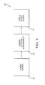
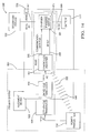
- FIG. 1 shows an electrical charging system (ECS) in simplified block diagram form that is configured to electrically charge an energy storage device (ESD) in accordance with the invention
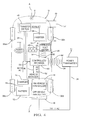
- FIG. 2 shows a more detailed block diagram of the ECS of FIG. 1 , and further details thereof including an alignment means;
- FIG. 3 shows the ECS of FIG. 2 , and further spatial details of the transducers thereof between a vehicle and a ground surface;
- FIG. 4 shows yet another block diagram of the ECS of FIG. 3 , further showing vehicular electrical signal shaping device (ESSD) details thereof;
- ESD vehicular electrical signal shaping device
- FIG. 5 shows a block diagram of a single power transmitter of the ECS of FIG. 2 , and details thereof;
- FIG. 5A shows an electrical schematic of the power transmitter of FIG. 5 ;
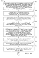
- FIG. 6 shows a method to operate the ECS of FIG. 2 that uses an alignment means of the ECS to ensure repeatable energy transmission of electromagnetic energy in an energy coupling arrangement;
- FIG. 7 shows further substeps of the method of FIG. 6 for positioning the vehicle so that the transducers are configured to wirelessly communicate one-to-another;
- FIG. 8 shows another method to operate the ECS of FIG. 2 based on data message transmission and acknowledgement
- FIG. 9 shows additional steps of the method of FIG. 8 ;
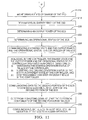
- FIG. 10 shows a method to transmit energy through the ECS of FIG. 2 using reflected and received power measurements
- FIG. 11 shows additional steps of the method of FIG. 10 ;
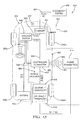
- FIG. 12 shows an ECS that includes a primary system similar to the embodiment of FIG. 2 and a 60 Hertz secondary system that electrically interfaces with the primary system, according to an alternate embodiment of the invention
- FIG. 13 shows an ECS that includes a primary and a secondary system and an integral charger electrical device as part of the ECS that has transfer switch functionality disposed therein, according to another alternate embodiment of the invention
- FIG. 14 shows an ECS that includes a primary and a secondary system and an integral charger electrical device that includes transfer switch functionality is incorporated therein is included as part of the primary system while the inverter electrical device is removed therefrom, according to a further alternate embodiment of the invention
- FIG. 15 shows a block diagram of a primary and a secondary system and the primary system includes a converter, according to another alternate embodiment of the invention.
- FIG. 16 shows a plurality of vehicles that respectively include the ECS of FIG. 2 being simultaneously electrically charged through a multiplex power switch according to yet another alternate embodiment of the invention.
- a drivetrain of a vehicle is formed with a group of components in the vehicle that generate power and deliver this power through the tires of the vehicle that engage a road surface.
- a hybrid electric vehicle and an electrical vehicle each use a traction battery to power the drivetrain of their respective vehicles.
- a hybrid electrical vehicle uses a hydrocarbon fuel engine, or motor in combination with energy supplied by a battery disposed on the vehicle to power the drivetrain of a vehicle.
- An electric vehicle powers the drivetrain solely by using energy from an energy storage device (ESD), or battery.
- ESD energy storage device
- the traction battery of the hybrid electric vehicle and the electric vehicle may include a plurality of batteries connected in series or parallel connection to form a single battery.
- the electrical charge on the battery may decrease, or become void of electrical charge. If this situation occurs, the battery needs to be electrically recharged back to a fully charged electrical state. Recharging a battery may be accomplished using an electrical charging system (ECS).
- ECS electrical charging system
- the ECS supplies the electrical charge to provide and fill the battery with electrical charge.
- a hybrid or electric vehicle's battery may be electrically charged using a plug-in 120 VAC, 60 Hertz (Hz) ECS when the vehicle is not in motion, such as when parked.
- Hz Hertz
- Alignment Means Structures that facilitate alignment of the vehicle so that the alignment of the transducers repeatedly occurs.
- Alignment means may include a wheel chock, a wheel stop, or a tire indention device.
- a wheel chock is one or more wedges of sturdy material placed ahead or behind a vehicle's wheels to prevent accidental movement of the vehicle. The bottom surface is sometimes coated in rubber to enhance grip with the ground.
- the wheel chock is positioned and secured to the ground surface using an adhesive or fasteners, and when engaged by the tires of the vehicle, ensures at least partial alignment of transducers of the ECS with one of the transducers disposed on the vehicle and another transducer being disposed on the ground surface.
- One edge of the wedge may have a concave profile to contour to the wheel of the vehicle that increases the force necessary to overrun the chock.
- Another type of alignment means may be a tire indention device. When the wheel is disposed within the indention of the tire indention device, this provides indication to a driver of the vehicle that the transducers of the ECS are in general alignment one-to-another so that an on-vehicle transducer may couple, or receive energy transmitted from the ground-based off-vehicle transducer.
- a lateral vehicle alignment member such as a tennis ball extending on a string from a ceiling of a residential garage, may also assist in helping the driver of the vehicle position the vehicle so that the transducers are sufficiently aligned so that the on-vehicle transducer wirelessly receives the energy transmitted from the off-vehicle transducer.
- the tennis ball may be positioned in a predetermined position so that when a front portion of the vehicle engages the tennis ball along a mid-line of the vehicle the vehicle is positioned so that at least a portion of the on-vehicle transducer overlies the off-vehicle transducer and energy is transmitted/received therebetween.
- the transducers may be considered aligned when the system power efficiency of the ECS is greater than 75% between the transducers. For example, for transducers having a general size of 50 centimeters (cm) x 50 cm with a z-axis direction of 20 cm having at least a 50% overlay of each area of the respective transducers may yield 75% or greater system power efficiency. In a general sense, if the system power efficiency of the ECS is greater than 75%, whether or not a portion of respective areas of the transducers overlie one another, the transducers may be considered to be aligned one-to-another. For example, as best illustrated in FIG. 3 , at least a portion of the area of the vehicular transducer preferably overlies at least a portion of the off-vehicle transducer secured to a ground surface underlying the vehicle.
- Charger Electrical Device An electrical device that takes one form of energy and converts it to a compatible form of energy to electrically charge the ESD of the vehicle.
- this charger device may receive low frequency AC power and converts it to DC current that is used to subsequently electrically charge a battery in a safe, efficient manner.
- the low frequency AC power may have a 60 Hz frequency associated with it.
- the energy coupling arrangement is formed from the off-vehicle transducer and the on-vehicle transducer.
- the on-vehicle transducer wirelessly receives electromagnetic (EM) energy transmitted from the off-vehicle transducer.
- EM electromagnetic
- the energy transfer is predominately through magnetic energy coupling.
- ESD Energy Storage Device
- the ESD may also be referred to as a battery.
- the battery may be a single battery or a plurality of batteries formed in to a battery pack.
- battery packs are typically found on electric or hybrid electric vehicles.
- ECS Power Efficiency The amount of power input relative to the amount of power output of the ECS.
- the system power efficiency may have a range from 0% to 100% with 100% being totally efficient with no loss of power between the input and the output.
- the system power efficiency may be affected by a number of factors one of which is the electrical components used to construct the ECS which may affect the power loss through the ECS. Also, this term may be referred to as 'system power efficiency.'
- the ESSD takes a form of energy as an input from the transducers, electrically shapes it in a manner suitable to electrically charge the ESD, and electrically transmits the shaped energy to the ESD.
- the ESSD is disposed on the vehicle electrically downstream from the on-vehicle transducer.
- the ESSD may be packaged with in a single electronic module or a plurality of modules electrically connected together dependent on the application of use for an electrical charging system.
- the ESSD may only be a rectifier.
- High Power ECS An electrical charging system (ECS) that has a power output from the power transmitter of at least 900 watts. Preferably, this wattage value is within a range from 900 to 10,000 watts. In some embodiments, an ECS having a power output from a power transmitter of less than 900 watts is not considered to be a high power ECS.
- the power output of the high power ECS generally also outputs an electrical signal that has a frequency that is greater than 60 Hz.
- the ECS includes a power transmitter in electrical communication with a power source, an energy coupling arrangement that includes a first and a second transducer, and an electrical signal shaping device (ESSD) that includes a controller.
- ESD electrical signal shaping device
- the ECS may also include an alignment means when used in vehicular applications that assists to properly align the second transducer in relation to the first transducer so that the second transducer receives energy from the first transducer when the ECS is in operation.
- an alignment means when used in vehicular applications that assists to properly align the second transducer in relation to the first transducer so that the second transducer receives energy from the first transducer when the ECS is in operation.
- FIGS. 4-5 12-15 various electrical signal designations are mapped along signal paths in the ECS to better understand the levels of voltage and/or frequency levels of these electrical signals within the various ECS embodiments.
- the ECS may not include an alignment means and still be within the spirit and scope of the invention.
- HV HF AC A high voltage, high frequency alternating current (AC) electrical signal.
- the voltage signal is greater than 120 VAC and the frequency of the voltage signal is greater than 60 Hz.
- the frequency may be in a range of 10 kHz to 450 kHz.
- HV DC - A high voltage, direct current (DC) electrical signal.
- the DC voltage is greater than 120 VDC.
- the AC voltage is either 120 VAC or 240 VAC dependent on the power source generating the voltage.
- this may be an electrical signal supplied by the power source to the primary system (240 VAC) or the secondary system (120 VAC, plug-in), such as illustrated in FIGS. 4 and 12 .
- the primary and/or the secondary system may be hardwired or pluggable dependent on the electrical application of use.
- Transducer - A device that converts energy from one form to another. For example, an off vehicle transducer converts electrical energy to EM energy and the on-vehicle transducer receives at least a portion of the EM energy and then converts this received EM energy back to electrical energy that may be used to electrically charge the battery.
- Power Source - This is power supplied by an electrical power grid such as is supplied by a power municipality.
- the high power ECS electrically connects to a power source.
- a conventional 60 Hz ECS also electrically connects with a power source.
- the power source in electrical connection with the high power ECS has a greater voltage than the power source in electrical communication with the 60 Hz ECS.
- a single power transmitter advantageously includes a DC supply, an RF amplifier, a wireless communication control, and a user interface within a single housing making for a compact, efficient arrangement that may be mounted to wall in a garage, for example, or to a post.
- An integrated power transmitter allows for overall ECS power efficiency to be attained versus having multiple electronic modules that might make up the functionality of power transmission. Multiple electronic modules may experience undesired loss of power that could otherwise result.
- the RF amplifier is in electrical communication with the DC supply.
- the first transducer is in electrical communication with an output of the RF amplifier.
- the RF amplifier is capable of delivering a power of greater than 900 Watts at a frequency of greater than 60 Hertz (Hz).
- the frequency has a range that is from 15 kHz to 450 kHz.
- the RF amplifier may also deliver a power of less than 900 Watts dependent on the operation mode of the ECS and the electrical application of use.
- the wireless communication control wirelessly communicates with the controller portion of the electrical signal shaping device (ESSD).
- Reflected Power An amount of energy not able to be wireless transmitted by the off-vehicle transducer. For example, the reflected power energy is affected by power that has been lost through the ECS en route to the battery.
- the motor is an electric motor.
- the hybrid electric vehicle includes an electric motor used in combination with and fuel combustion engine to power the drivetrain of the vehicle.
- a high power ECS 10 is configured to electrically charge an ESD 12 that further drives one or more electrical loads.
- ESD 12 may be a traction battery.
- ESD 12 is disposed on a ground-based vehicle 13 and configured to provide energy to operate a drivetrain (not shown) of vehicle 13.
- the ESD is not limited to supplying electrical current only to the drivetrain, but may also be used to operate any electrical or electrical/mechanical device that requires electrical current.
- the vehicle may be any type of vehicle that has an ESD, or battery that needs electrical charging and includes, but is not limited to a hybrid and/or a hybrid electric vehicle.
- ESD 12 may be formed as a single battery or a plurality of batteries such as may be arranged in a battery pack.
- a first portion of ECS 10 is disposed external to vehicle 13 and a second portion of ECS 10 is disposed on vehicle 13.
- Vehicle 13 has a length disposed along a longitudinal axis A, as best illustrated in FIGS. 3 and 4 , and is further disposed along a generally planar ground surface 27.
- ECS 10 includes an integrally constructed power transmitter 14, a first, or off-vehicle transducer 16, a second, or on-vehicle transducer 18, at least one on-vehicle electrical signal shaping device (ESSD) 20, and an alignment means 22.
- ESSD on-vehicle electrical signal shaping device
- 'off-vehicle' provides an indication that the device is disposed external to the vehicle and 'on-vehicle' provides an indication that the device is attached or disposed on the vehicle.
- ECS 10 including ESSD 20 may be formed of any type of electrical/electronic devices in any type of circuit combination and may include resisters, capacitors, diodes, semiconductors, integrated circuits (ICs), relays, thermal fuses, thermistors, and thermocouples, transducers, coils and the like.
- the first portion of ECS 10 disposed external to vehicle 13 includes power transmitter 14 and off-vehicle transducer 16 in electrical communication with power transmitter 14. Off-vehicle transducer 16 is fixedly secured to ground surface 27 with fasteners, such as bolts.
- the second portion of ECS 10 is disposed on vehicle 13 includes on-vehicle transducer 18 and ESSD 20 in downstream electrical communication with on-vehicle transducer 18.
- Vehicle 13 includes a charger electrical device 24 and battery 12 in downstream electrical communication with charger 24.
- Vehicular charger 24 is in disposed in downstream electrical communication from ESSD 20.
- Power transmitter 14 is in downstream electrical communication with a fixed power source 26.
- Power source 26 has a voltage value that is greater than the 120 VAC, 60 Hz power source used to operate the pluggable, portable charging system as discussed previously in the Background.
- fixed power source 26 has a voltage value of 220 or 240 VAC.
- the fixed power source in electrical communication with the power transmitter may have any voltage value that is greater than 120 VAC.
- system 10 is configured to electrically charge battery 12 in a lessor amount of time than the 60 Hz, 120 VAC pluggable, portable charge system previously discussed herein.
- ECS 10 is configured to electrically charge battery 12.
- Transducers 16, 18 form an energy coupling arrangement 28 and on-vehicle transducer 18 and ESSD 20 form a mobile power system 31 of ECS 10.
- Mobile power system 31 is carried with vehicle 13 as vehicle 13 movingly travels along a road.
- the on vehicle and off-vehicle transducers 16, 18 are constructed with a coil that may have a high quality factor (Q factor) and may be formed of litz wire or copper tubing so that the coil has low resistance at the frequency of operation. Dependent on the electrical application, the Q factor may be greater than 100.
- the transducers may also include additional electrical components, such as resistors, capacitors, inductors and the like to ensure high efficiency transmission of the magnetic energy therebetween.
- mobile power system 31 is a vehicle-based subsystem that is disposed in downstream communication from energy coupling arrangement 28 and energy coupling arrangement 28 is disposed in downstream electrical communication from fixed power source 26, as best illustrated in FIG. 1 .
- EM energy is wirelessly transmitted from off-vehicle transducer 16 to on-vehicle transducer 18 within energy coupling arrangement 28. It is desired that the on- and off-vehicle transducers each have an operating temperature range from -30 degrees to +50 degrees Celsius.
- Power transmitter 14 is in electrical communication with a fixed power source 26 and off-vehicle transducer 16. As such, power transmitter 14 and fixed power source 26 form a ground-based wireless power transmitter subsystem. Power source 26 is disposed external to ECS 10 and vehicle 13. Preferably, power transmitter 14 is hardwired with power source 26 so as to eliminate handling of high voltage power cables electrically connecting power source 26 and power transmitter 14 by a human operator 32 so as to increase the safety of human operator 32 and provide further convenience for operator 32 in the operation of ECS 10. For example, as best shown in FIG. 3 , human operator 32 may be the driver of vehicle 13. Alternately, the human operator may be any person that has access to system 10.
- Power transmitter 14 is in electrical communication with off-vehicle transducer 16 through electrical wire cables 34 that carry an electrical output of power transmitter 14.
- power transmitter 14 is configured to supply energy used by ECS 10 to form electrical current that is provided to electrically charge ESD 12.
- Off-vehicle transducer 16 is in wireless communication with on-vehicle transducer 18 in arrangement 28 in that on-vehicle transducer 18 wirelessly receives, collects, or couples at least a portion of the energy transmitted by off-vehicle transducer 16 from energy provided by power transmitter 14 via fixed power source 26.
- EM energy is wirelessly communicated, or transmitted from off-vehicle transducer 16 to on-vehicle transducer 18.
- the transducers of the energy coupling arrangement may wirelessly communicate by wireless inductive energy communication or wireless electrical communication. Another form of electrical wireless communication may be capacitive coupling.
- ESSD 20 advantageously electrically shapes communicated EM energy received and captured by on-vehicle transducer 18 to produce electrical current in a form useable by ESD 12.
- the produced electrical current is electrically transmitted through ESSD 20 to electrically charge ESD 12.
- this electrical current is in a form that is useable by a charger prior to the battery being electrically charged.
- Alignment means 22 is disposed external to vehicle 13 on ground surface 27, as best illustrated in FIG. 3 .
- Alignment means 22 is a tire block, or wheel chock 37 that is configured for physical engagement, or contact with at least one of the tires 38a-d of vehicle 13.
- Wheel chock 37 may be commercially purchased or molded by an injection molding machine as is known in the molding art. Wheel chock 37 is positioned on ground surface 27 and may be secured to ground surface 27 using bolts or other type fasteners. As best shown in FIGS. 3 and 4 , wheel chock 37 is engaged with right front tire 38b. Alternately, the wheel chock may be strategically positioned in a manner along the ground surface so that any tire on the vehicle could be appropriately engaged such that the transducers wirelessly communicate EM energy therebetween.
- wheel chock 37 ensures vehicle 13 is positioned relative to off-vehicle transducer 16 of arrangement 28 such that the on-vehicle transducer 18 receives the EM energy wirelessly transmitted from off-vehicle transducer 16.
- On-vehicle transducer 18 is fixedly attached to vehicle 13, preferably on an underside portion 39 of vehicle 13, so that an extended surface of on-vehicle transducer faces towards ground surface 27.
- the on-vehicle transducer may be mounted to a bracket or component frame (not shown) being attached to the vehicle's frame using a fasteners such as bolts or strap ties and the like.
- on-vehicle transducer 18 is mounted at the rear of vehicle 13.
- the on-vehicle transducer may be mounted anywhere along the underside of the vehicle.
- the on-vehicle transducer may be mounted anywhere on the vehicle so that the on-vehicle transducer effectively receives energy supplied and transmitted by the off-vehicle transducer when sufficiently proximately spaced one-to-another so that EM energy communicated therebetween.
- wheel chock 37 allows driver 32 of vehicle 13 to repeatedly position vehicle 13 so that so that at least a respective portion of transducers 16, 18 are axially aligned along axis B when tire 38b of vehicle 13 engages against a strategically positioned wheel chock 37.
- wheel chock 37 is strategically positioned so that a majority portion of on-vehicle transducer 18 overlies off-vehicle transducer 16 when tire 38b engages wheel chock 37, as best illustrated in FIG. 3 .
- wheel chock 37 is positioned on ground surface 27 at a location so that when at least one of the tires 38a-d of vehicle 13 is positioned and communicates with wheel chock 37 by engaging wheel chock 37, the on-vehicle transducer 18 is also positioned relative to off-vehicle transducer 16 so that EM energy is effectively communicated therebetween from off-vehicle transducer 16 to on-vehicle transducer 18.
- the alignment means may be an automotive wheel stop or at least one tire indention device.
- the wheel chock may have a weight that is sufficient to be engaged by at least one tire of the vehicle and not further move so that wireless communication between the transducers occurs.
- wheel chock 32 is securely positioned on ground surface 27 at a location such that when engaged by tire 38b of vehicle 13 to ensure that at least a portion of on-vehicle transducer 18 overlies at least a portion of off-vehicle transducer 16 along an axis B, as best illustrated in FIG. 3 .
- Axis B is transverse to ground surface 27 and axis A.
- the alignment of at least a portion of one transducer 18 overlying the other transducer 16 along axis B ensures that EM energy is wirelessly communicated between transducers 16, 18.
- wheel chock 32 is positioned so that a majority portion of on-vehicle transducer 18 axially overlies off-vehicle transducer 16 along axis B. Additionally, when vehicle 13 communicates, or engages with wheel chock 37, a sensory response is produced as a result of vehicle 13 communicating with wheel chock 27.
- At least one sense organ of driver 32 disposed in vehicle 13 senses this sensory input, such that when the at least one sense organ senses the sensory input, at least a portion of on-vehicle transducer 18 of energy coupling arrangement 28 overlies off-vehicle transducer 16 of energy coupling arrangement 28.
- the human sense organs are generally recognized as sight by the human eye, smell by the human nose, taste by the human mouth, touch by the human skin, and hearing by the human ear.
- the skin of the driver feels the touch of the 'bump' from the tire of the vehicle engaging the wheel chock which is an indication to the driver of the vehicle to stop movement of the vehicle.
- any alignment means that allows the on-vehicle transducer to overlie at least a portion of the off-vehicle transducer so that EM energy is wirelessly communicate therebetween falls within the spirit and scope of the invention.
- transducers 16, 18, are in general alignment along axis external facing surfaces of transducers 16, 18 separated by a distance d, as best illustrated in FIG. 3 .
- the axial space that spans distance d is an air gap.
- distance d may be a 15 to 20 centimeter distance in which a 3.3 kW signal out the power transmitter may be effectively transferred.
- a vehicle alignment member 41 may also be advantageously used by driver 32 to assist driver 32 to further laterally align the left/right spacing of vehicle 13 when aligning transducers 16, 18.
- one such aligning member 41 is a tennis ball hung from a rope from a ceiling in a home garage or office parking structure and strategically positioned so that when a front end of vehicle 13 engages the tennis ball, driver 32 knows transducers 16, 18 are at least partially in alignment along axis B one-to-another.
- ESSD 20 is adapted to electrically shape at least a portion of the energy received by on-vehicle transducer 18 and electrically transmit this electrically-shaped energy to electrically charge ESD 12.
- ESSD 20 includes controller/rectifier block 40 that includes a controller and a rectifier, a ballast resistor 42, a wireless voltmeter 44, an inverter 46, and a transfer switch 48.
- An electrical output 52 of on-vehicle transducer18 is electrically received by controller/rectifier block 40.
- An electrical output 54 of controller/rectifier block 40 is electrically received by inverter 46.
- the controller portion of the controller/rectifier 40 may be a microcomputer or a microprocessor as is known in the electrical arts.
- the controller portion of the controller/rectifier block 40 has wireless data transmission 62 with power transmitter 14 and receives wireless data transmission 64 from power transmitter 14. Data is also electrically wirelessly communicated 66 from wireless volt meter 44 to the controller portion of controller/rectifier.
- the controller portion of controller/rectifier block 40 also electrically communicates data on a vehicle communication data bus 60 with other vehicular electrical devices.
- Data communication monitored by the controller portion of the controller/rectifier block 40 centers around the present electrical charge condition, or state of battery 12. Alternately, the inverter may not be utilized. If an inverter is not used in the ESSD of the ECS the overall system power efficiency of the ECS is desirably increased, the vehicle weight is desirably reduced, and the parts complexity of the ECS is also desirably reduced improving the reliability of the ECS.
- Charger 24 is disposed in vehicle 13 external to system 10 being associated with the vehicular electronics similar to battery 12 previously described herein. These electrical devices may be disposed on printed circuit boards housed in a single unit or in multiple units as required by the application of use. Alternately, the controller/rectifier block of the ESSD may be disposed as separate, distinct controller and rectifier functional blocks within the ECS. The controller may also operate an algorithm that presents input to the controller that receives information from the vehicle on the data communication bus on the present state of the electrical charge of the battery for determining a new rate of electrical charge that will be allowed by the battery. The newly input information then will determine a new rate of electrical charge allowed for the battery.
- One such algorithm is described in U.S. Patent No. 7,800,344 entitled "METHOD OF DETERMINING THE ENERGY CAPACITY OF A BATTERY”.
- Power transmitter 14 receives electrical energy from power source 24, amplifies the received energy, and supplies the amplified received energy to off-vehicle transducer 16.
- Off-vehicle transducer 16 wirelessly electromagnetically transmits or propagates at least a portion of the amplified energy to on-vehicle transducer 18.
- On-vehicle transducer 18 receives at least a portion of the EM energy transmitted from off-vehicle transducer 16.
- On-vehicle transducer 18 transmits this received energy to ESSD 20 that electrically shapes and electrically transmits this electrically-shaped energy to subsequently electrically charge battery 12 on vehicle 13.
- ESSD 20 electrically shapes and electrically transmits this electrically-shaped energy to subsequently electrically charge battery 12 on vehicle 13.
- the vehicle charger is readily able to accept an output of the invertor without additional modification or cost to the overall ECS system.
- One undesired disadvantage of using an inverter in the ECS may be lower system power efficiency of the overall ECS due to an extra electrical component in the ECS that may be subject to system power efficiency losses.
- the energy supplied by fixed power source 26 is received by power transmitter 14 that produces a DC voltage via DC supply 70 that is modulated and provided electrical gain by amplifier 72 to become a high frequency AC voltage that is output from amplifier 72 and further output from power transmitter 14 on wire cables 34.
- the high frequency AC voltage output from amplifier 72 may be in range from 10 kHz to 450 kHz. More preferably, this range is from 90 kHz to 170 kHz.
- the higher frequency also allows for the transducers to be constructed having less mass, less size than would be required if lower frequencies where utilized. Less mass may advantageously allow the vehicle to travel a longer distance than may otherwise be able for a given amount of electronic charge of the battery. This may allow further flexibility in locating the transducers on the vehicle and on the ground surface when initially setting up the ECS. Also allows for greater distance d clearance as, best illustrated in FIG. 3 . With a higher system power efficiency, a lower energy cost may desired by the user to electrically charge the battery.
- the high frequency, high AC voltage is electrically transmitted to off-vehicle transducer 16 which wirelessly transmits at least a portion of this energy to, and received by on-vehicle transducer 18 and further electrically transmits this portion along signal path 52 to controller/rectifier block 40.
- the rectifier portion of the controller/rectifier block 40 electrically rectifies this voltage to produce a corresponding direct current (I DC ).
- This I DC current is electrically transmitted along signal path 54 to inverter 46 which inverts the corresponding DC current to produce a 50-60 Hz electrical current useful to electrically charge battery 12.
- This 50-60 Hz electrical current is transmitted along signal path 58 to transfer switch 48.
- Power transmitter 26 includes a metal enclosure, or housing that surrounds DC supply 70, amplifier 72, user interface 74, and wireless communication control 76.
- User interface 74 may include LEDs, audible alarms, and a control panel.
- the LEDs and audible alarms may indicate fault or status conditions to the human operator of the system. In other embodiments, fault conditions and/or audible alarms may sound off if the transducers are not sufficiently aligned as described herein so that the ECS may electrically charge the battery.
- the gist of these features includes getting the attention of the human operator that the battery is not being charged when it should be and describing to the human operator where the fault lies so the problem may be fixed before the human operator leaves the local area of the ECS and the vehicle.
- the human operator may leave the local area and come back to the vehicle at a later time to find out that the battery had not been electrically charged. This would be an undesired situation as the human operator may not be able to operate the vehicle over a desired distance that has less than a full level of electrical charge.
- the power transmitter includes a fan for cooling the electronics contained therein.
- Wire cables 34 may further be contained within a liquid-tight, flexible metal conduit for high voltage, high frequency signal carried on wire cables 34.
- the power transmitter may further include a head sink to wick heat away from the amplifier on communication control electronics.
- the power transmitter electrical connection to the power source may be contained in a flexible metal conduit.
- the power transmitter may include provisions to attach the power transmitter to a mounting bracket that can further be attached to a wall.
- Transfer switch 48 is selectably controlled to a first or a second position by the controller portion of controller/rectifier block 40 along control signal path 56.
- Control of transfer switch 48 by the controller portion of the controller/rectifier block 40 is one approach that allows system 10 to control a rate of electrical charge provided to battery 12.
- transfer switch 48 is set to a first position, the 50-60 Hz electrical current is carried on electrical output 58 of inverter 46 is received by charger 24 along signal path 61.
- transfer switch 48 is set to a second position by the controller portion of the controller/rectifier block 40, the electrical output of inverter 46 is not received by charger 24 along signal path 61.
- Transfer switch 48 is in electrical communication with a vehicle charger 24 that regulates and controls the voltage that is useful to electrically charge battery 12.
- Vehicle charger 24 is used by electrical systems of vehicle 13 to allow independent vehicular control of battery charging independent of system 10. Thus, charger 24 may further modify or manage the electrical charging of battery 12 from electrical current received from system 10 as controlled by electronics disposed in vehicle 13. Alternately, the vehicle charger may not be employed.
- controller/rectifier block 40 communicates with electrical components disposed on vehicle 13 through a vehicle data communication bus 60.
- the transfer switch may be controlled by another electrical device in the vehicle through the vehicle data communication bus communicating with controller/rectifier block 40.
- Vehicle data communication bus 60 may communicate vehicle status information to system 10.
- Wireless voltmeter 44 measures the magnitude of the voltage and/or electrical current along signal path 54 of controller/rectifier block 40. This voltage information is wirelessly communicated with a receiver portion of the controller/rectifier block 40 in system 10. Knowing the on-board vehicle voltage information allows for the variable adjustment of off-vehicle transducer 16 by system 10 to optimize electrical operation of system 10. The energy flow out of the RF amplifier is adjusted based on the voltage.
- Ballast resistor 42 is used to minimize the magnitude of the voltage along signal path 54 during electrical start-up of system 10. Alternately, the ballast resistor may not be used in the ECS.
- the electrical current available to charge the battery along signal path 61 may be in a range of 10-20 amps DC.
- the electrically-shaped energy electrically transmitted in to ESSD 20 has a first frequency along signal path 52 and a second frequency along signal path 61 electrically output from transfer switch 48 transmitted to charger 24 and subsequently to battery 12.
- the first frequency is greater than the second frequency.
- the second frequency is at least 45 Hz and the first frequency is disposed in a range from 20 kHz to 200 kHz in contrast to the frequency of an electrical output signal on wire cables 34 from power transducer 14.
- power transmitter 14 includes a housing 75 that encloses a plurality of electrical components (not shown) in an integral package.
- the housing may be constructed of any solid material such as metal or plastic where the metal material may be stamped into form or the plastic material molded.
- the electrical components form a respective first electrical portion, a second electrical portion, a third electrical portion, and a fourth electrical portion within housing 75.
- the portions may be formed on one or more printed circuit boards disposed within housing 75.
- Power transmitter 14 has an electrical output carried on wire cables 34 in electrical communication with off-vehicle transducer 16.
- the first electrical portion is a DC power supply 70.
- the second electrical portion is amplifier 72 in electrical communication with DC power supply 70.
- the third electrical portion is a user interface 74.
- User interface 74 provides operating condition information of ECS 10 to human operator 32.
- user interface 74 is very useful to alert the human operator of an issue with that would keep the ECS from electrically charging battery. Additionally, it is also advantageous to do so after the human operator, such a driver of the vehicle, exits the vehicle is still in the local area of the ECS. Thus, it is important to get the driver's attention if some condition prevents the ECS from charging the battery. It is also important, the once the driver's attention is focused on the fault condition, that the ECS educate and inform the driver on how to fix the faulty condition so the ECS is allowed to electrically charge the ESD.
- the battery may undesirably remain in an uncharged state, when the human operator otherwise expected the battery to be a fully charged electrical state. For example, if the vehicle is not properly aligned so the second transducer receives energy from the first transducer, or if the vehicle's transmission is not disposed in the 'park' position, these types of conditions may prevent the battery from being electrically charged.
- User interface has at least one visual element 78 seen by eyes of human operator 32.
- Visual element 78 is preferably an LCD display.
- LCD 78 includes four (4) alphanumeric lines that each display different performance metrics of ECS 10.
- a first alphanumeric line displays information about the general operating conditions of ECS 10.
- a second alphanumeric line displays the output voltage of rectifier portion of controller/rectifier 40 and the output voltage and power output delivered from the controller/rectifier 40 to the remaining portion of the ECS and the vehicle.
- a third alphanumeric line displays shows a DC voltage supplied by DC supply 70 to RF amp 72 of power transmitter 14.
- a fourth alpha numeric line displays the system power efficiency.
- the LCD display may have other arrangements for display information, for instance, error messages when the ECS experiences a fault condition that is useful to the human operator for the operation of the ECS.
- Power transmitter 14 also contains a multicolored light 79.
- Light 79 may be operated to alter between different colors of light to indicate various operational status conditions of ECS 10. For example, the light may change from green to yellow to red in which may be an undesired ECS system fault that keeps ECS 10 from electrically charging ESD 12. A red colored light due to a fault may alternately be displayed on the LCD display.
- At least one audible element may be heard by ears of human operator.
- an audible noise may be generated through an audio output, such as to a speaker, that provides an indication to the human operator that the ECS is not electrically charging the ESD. This would further get the human operator's attention before leaving the local area of the vehicle and the ECS to correct the problem.
- the user interface includes at least one visual element and at least one audible element.
- User interface 74 comprises at least one provision 79 that allows human operator 32 of ECS 10 to command ECS 10 to perform at least one operation.
- Provision 79 is an ON/OFF push button to turn power transmitter 14 electrically ON so power transmitter 14 is energized to produce energy to transmit to off-vehicle transducer 16 or electrically OFF in which power transmitter is powered down and energy is not transmitted to off-vehicle transducer 16.
- User interface 74 includes an LCD display. Alternately, the user interface may include any number of LEDs, lights, a LED display, and at least one push button.
- the fourth electrical portion is a wireless communication control section 76 that wirelessly electrically communicates through antenna 80 with a portion of ECS 10 disposed on vehicle 13.
- Fourth section 76 is a computer or microprocessor as is known in the art.
- Power transmitter 14 analyzes the received data from the controller portion of controller/rectifier block 40 via wireless communication control 76 and adjusts DC power supply 70 to ensure that an output of the rectifier portion of controller/rectifier block 40 is within a range dependent on the electrical application of use for the system 10.
- Control 76 may also be used as a receiver/transmitter to communicate with charger 24 and other electronic devices of vehicle 13 through the vehicle data communication bus 60 to ensure optimal electrical charging of battery 12.
- the controller portion of the controller/rectifier block 40 may also receive/transmit data to charger 24 through vehicle communication data bus 60.
- An electrical signal carried on wire cables 34 that is output from power transmitter 14 has a frequency of greater than 60 Hz and a power output of greater than 900 watts electrically transmitted to off-vehicle transducer 16.
- the power transmitter transmits 3.3 kilowatts (kW).
- the electrical signal carried on cables 34 has a frequency value that is disposed in a range from 15 kHz to 450 kHz.
- 3.3 kW output out from the power transmitter may electrically charge a battery having a low level of electrical charge in about 4 hours of time.
- a battery electrically charged to a full level of electrical charge may allow a vehicle containing the battery to travel up to a maximum of 64.7 km (40 miles).
- ECS 10 is formed to have a system power efficiency that is the same as, or is greater than 75%.
- the 75% or greater system power efficiency is a desired level so that the ECS is cost effective to operate for the human operator. Having less than 75% may be undesired as this may not be cost effective for the human operator to operate the ECS.
- having a number greater than 75% may be even more desirable as the cost of operating the ECS becomes even less for the human operator.
- Children and/or pets may be in close proximate to the off-vehicle transducer during electrical charging of the EDS.
- a human occupant may occupy the vehicle during the electrical charging of the ESD.
- the ECS may adjust output voltage from the power transmitter based upon different ESD battery voltages used by different vehicle manufacturers. Sending data across the data communication link is required before the ECS may initiate electrical charging of the ESD.
- the RF amplifier of the power transmitter will not be activated until electrical charging of the ESD is requested by the vehicle's electronic devices.
- System power efficiency may remain the same as or greater than 75% efficient as the electrical charge current progressively decreases during the electrical charge cycle.
- Reference numerals 62, 64, and 66 represent wireless electrical signal energy paths to transmit electronic data between various electrical components in ECS 10.
- Volt meter 44 measures voltage along signal path 54 of ESSD 20 and wirelessly transmits this data measurement information to controller/rectifier 40.
- Wireless electrical signal energy 62 is wirelessly transmitted from controller/rectifier 40 to power transmitter 14.
- Power transmitter 14 actively receives signal energy 62.
- Power transmitter 14 also wireless transmits data information to controller/rectifier 40.
- the purpose of the wireless energy transmission of signal energy along signal paths 62, 64, 66 is to optimize the operational performance of ECS 10 to electrically charge ESD 12. More particularly, the ECS is configured to optimize real-time ECS operation and ensure the system power efficiency is, and remains greater than 75%.
- the controller portion of controller/rectifier 40 may measure the electrical current output on signal path 54.
- the controller portion of controller/rectifier may also mathematically generate power readings along signal path 54, having the electrical current data and the voltage data from volt meter 44. Alternately, the power may be also be actually measured.
- the electrical voltage, electrical current, or power data may be sent to power transmitter 14 on wireless signal path 62. Power transmitter 14 receives this data can then adjust its output signal on signal path 34 to maintain a power system efficiency of ECS 10 at greater than 75 % while ECS is electrically charging ESD 12.
- Power transmitter 14 requests controller/rectifier 40 for voltage, current, or power data along wireless signal path 64. In some embodiments, power transmitter 14 may request only one type of data, or any combination of data as is required by power transmitter 14. Alternately, the controller/rectifier may periodically send any or all of this data to the power transmitter along with wireless data signal path.
- ECS 10 is not in use when power transmitter 14 is not in communication with power source 24. ECS 10 is also not in use when power transmitter 14 is in communication with power source 24 and the ON/OFF switch 82 on user interface 74 has not been activated by human operator 32. When ON/OFF switch 82 is unactivated ECS 10 is in an OFF state such that ESD 12 cannot be electrically charged by ECS 10.
- ECS 10 is partially in use when system 10 is in electrical communication with power source 26 and ECS 10 is in an ON state, but transducers 16, 18 are spaced sufficiently far apart so the EM energy in not wirelessly transmitted/recieved therebetween. For example, it may not be necessary for transducers to at least partially overlie one another for ECS 10 to electrically charge ESD 12. If transducers are sufficiently spaced part, either axially or laterally and the ECS has a system power efficiency measured at 75 % efficiency or greater by power transmitter 14, ECS 10 will electrically charge ESD 12 if electrical charge is needed by ESD 12. Power transmitter 14 looks at power, voltage, and current carried on output, or wire cables 34 to determine whether ECS 10 electrically charges ESD 12 and at what rate ESC 10 electrically charges ESD 12.
- ECS 10 electrically charges battery 12 of vehicle 13 by method 100.
- One step 102 in method 100 is providing ECS 10 which includes power transmitter 14, energy coupling arrangement 28, at least one electrical signal shaping device (ESSD) 20, and wheel chock 32, all of which is previously described herein.
- Another step 104 in method 100 is electrically energizing power transmitter 14 of ECS 10 so that off-vehicle transducer 16 includes energy.
- a further step 106 in method 100 is aligning on-vehicle transducer 18 of energy coupling arrangement 28 in relation to off-vehicle transducer 16 when vehicle 13 communicates with wheel chock 37 such that on-vehicle transducer 18 is configured to recieve the energy wirelessly transmitted from off-vehicle transducer 16.
- Another step 108 in method 100 is receiving at least a portion of the wirelessly transmitted energy by on-vehicle transducer 18 from off-vehicle transducer 16.
- a further step 110 in method 100 is electrically shaping the portion of the received energy through on-vehicle transducer 18 by ESSD 20 to produce an electrical charging current configured to electrically charge ESD 12.
- ECS 10 may control electrical charging of ESD 12 by use of an algorithm as previously described herein or controlling the power output to the first transducer by the power transmitter, or the controller controlling the operation of the transfer switch.
- Another way of controlling the electrical charging of the ESD is for the user to activate ON/OFF switch 79 to turn the ECS OFF to a non-powered state so that electrical signals carried on wire cables 34 do not occur.
- the aligning step 106 of method 100 further includes the following substeps 114, 116, 118, 120 to further align vehicle 13 so that vehicle 13 may engage wheel chock 37.
- Using lateral vehicle alignment member 41 may further assist driver 32 to position vehicle 13 in an efficient manner.
- ECS 10 is disposed in a fixed location, such as a home garage or a parking structure, vehicle 13 needs to movingly approach ground-based off-vehicle transducer 16 and ground-based wheel chock 37 so that the transducers 16, 18 may be configured to wirelessly transmit/recieve energy therebetween.
- substep 114 of method 200 is movingly approaching, with vehicle 13, towards wheel chock 37.
- Substep 116 is detecting lateral left or right side tire displacement of vehicle 13 by driver 32 of vehicle 13 and make tire displacement adjustments to align on-vehicle transducer 18 with off-vehicle transducer 16.
- Substep 118 of method 200 is to continue approaching wheel chock 37 with vehicle 13 having the adjusted tire displacement, and substep 120 of method 200 is stopping movement of vehicle 13 by driver 32 when driver 32 senses with one of the human senses that at least one tire 38 of the vehicle has engaged at least one wheel chock 37.
- a method 130 is presented to electrically charge an ESD in a vehicular ECS.
- One step 131 in method 130 is providing the ECS that includes a power transmitter, an energy coupling arrangement, at least one electrical signal shaping device (ESSD) that includes a controller and a transfer switch, and the energy coupling arrangement includes an off-vehicle transducer and an on-vehicle transducer, the off-vehicle transducer being in electrical communication with the power transmitter and the on-vehicle transducer being disposed on the vehicle, and the ESSD being in electrical communication with the on-vehicle transducer.
- ESD electrical signal shaping device
- Another step 133 in method 130 is periodically activating an amplifier in the power transmitter by the ECS to determine if the vehicle is in a distance range in which the off-vehicle transducer is effective to transmit energy to the on-vehicle transducer.
- a further step 135 in method 130 is electrically transmitting a data message from the power transmitter to the ESSD that is further electrically transmitted to electronic devices in the vehicle to indicate to the electronic devices in the vehicle that electrical charging of the ESD by the ECS is available.
- a further step 137 in method 130 is acknowledging the data message by the vehicular electronic devices to the ECS.
- Another step 139 in method 130 is determining, by the vehicular electronic devices, that ESC charging conditions to electrically charge the ESD are met.
- a further step 141 in method 130 is transmitting an electrical charge request from the vehicle to the power transmitter.
- Another step 143 in method 130 is acknowledging the electrical charge request by the vehicle to the ECS.
- a further step 145 in method 130 is transmitting a required charge voltage message by the vehicle to the ECS.
- Another step 147 in method 130 is acknowledging the required charge voltage message by the ECS so that the ECS adjusts a voltage of the ECS to electrically charge the ESD.
- a further step 147 in method 130 is energizing the transfer switch. Alternately, in other ECS configurations that include only ECS 10 may not require the transfer switch to be energized.
- Another step 149 in method 130 is transmitting a ready to electrically charge data message from the vehicular electronic devices to the ECS.
- a further step 151 in method 130 is acknowledging the ready to electrically charge message by the ECS to the vehicular electronic devices.
- Another step 155 is method 130 is electrically charging the ESD by the ECS.
- Wireless signal paths 62, 64, and 66 transmit voltage, current, and/or power data, as previously described herein, that is useful in determining the reflected and received power measurements as described in method 200, more particularly steps 206 and 208.
- Temperature data measured from transducers (not shown) disposed adjacent on-board transducer 18 may also be sent along wireless signal path 62 to power transmitter 14. This data is useful for the monitoring temperature step 213 of method 200.
- ECS 10 includes other conditions be present to electrically charge battery 12.
- One condition that ECS 10 needs to know is whether battery 12 even needs to be electrically charged.
- Another condition ECS 10 needs to know is if the transmission of vehicle 13 is in the PARK position so that vehicle 13 that provides an indication to the ECS that vehicle 13 is not in motion.
- a further condition the ECS 10 needs to know is if an ignition key of vehicle 13 is in the OFF position along with the vehicle's audio and video electronic devices being de-energized.
- the ECS may additionally need to know that no human operator of the vehicle is disposed within the vehicle cabin space before the ECS will electrically charge the ESD.
- These above-mentioned conditions may be monitored by ECS 10 over vehicle data bus 60. Alternately, any combination of the abovementioned conditions may be used as conditions for the ECS to operate to electrically charge the battery. Still yet alternately, none of these aforementioned conditions need be present for the ECS to operate to electrically charge the battery.
- method 130 When the ESD has a full state of electrical charge, and method 130 further includes a step 157 of electrically transmitting a charge complete data massage from the vehicular electrical devices to ECS 10. Another step 159 in method 130 is acknowledging, by the ECS, the charge complete data message.
- a further step 161 in method 130 is de-energizing amplifier 72 of power transmitter 14 of ECS 10 and transfer switch 48 of ECS 10 by ECS 10.
- Another step 163 in method 130 is electrically transmitting a power off data message to the vehicular electronic devices by ECS 10.
- ESD 10 when ESD 10 is in use a method 200 to transmit energy through ECS 10 to electrically charge battery 12 is now presented.
- One step 202 in method 200 is providing ECS 10 that includes power transmitter 14, energy coupling arrangement 28, at least one electrical signal shaping device (ESSD) 20, and wheel chock 37, as previously described herein.
- Another step 204 in method 200 is transmitting a pulse signal from off-vehicle transducer 16 to on-vehicle transducer 18. For example, one such pulse has a value of 50 +/- 10 Watts for a time period of 30 +/- 10 seconds.
- the pulse signal is sent out when an ignition key of vehicle 13 is in the OFF position and the transducers 16, 18 are aligned as previously described herein.
- the pulse signal may be sent out when the transducers are aligned as previously described herein regardless of the position of the ignition key.
- a further step 206 in method 200 is determining, by ECS 10, a reflected power measurement of ECS 10 as a function of the pulse signal.
- Another step 208 in method 200 is determining, by ECS 10, a received power measurement as a function of the pulse signal.
- a further step 210 in method 200 is transferring the energy to electrically charge battery 12 by ECS 10 when the reflected power measurement is less than a predetermined first threshold value and the received power measurement is greater than a predetermined second threshold value, and the predetermined second threshold value is greater than the predetermined first threshold value.
- the predetermined first threshold value is 25% and the predetermined second threshold value is 75%.
- fault electrical signals and ECS diagnostic fault codes would be set. These fault codes would be sent to the vehicle through the vehicle communication data bus 60.
- various faults that may be detected include temperature of the battery, battery state of health, battery state of charge, state of the vehicle harness of to/from the battery to identify shorts, opens, and isolation in the harness, object detection between the transducers, temperature of the transducers, and coil damage between the transducers.
- ECS 10 checks voltage and current amplitude and their corresponding phase relationship at output 34 from power transmitter 14.
- step 210 of transferring the energy is performed every 10 +/- 1 minute during step 210 of transferring the energy to battery and monitored by power transmitter 14.
- Step 210 may be interrupted by the human operator such as if the on/off button is pressed on power transmitter 14.
- Step 210 may also be interrupted by ESSD 20 if ECS 10 detects a vehicle fault as previously discussed herein.
- Another step 212 in method 200 is that step 210 of transferring the energy further includes starting an internal timer when step 210 of transferring the energy begins.
- a further step 213 in method 200 is monitoring temperature, respectively, at off-vehicle transducer 16 and at on-vehicle transducer 18 thereat.
- a further step 214 in method 200 is continuously determining the reflected power measurement and the received power measurement after the step of starting the internal timer.
- Another step 216 in method 200 includes when an ECS power efficiency is less than a predetermined amount of system power efficiency and the internal timer is less than a threshold value and a value of the temperature is less than a predetermined amount, then monitor a state of electrical charge of battery 12 as listed in step 216.
- the predetermined amount of the system power efficiency is less than 75%
- the internal timer is less than eight (8) hours
- the value of the temperature is less than 90 degrees Celsius.
- the step 216 of method 200 further includes a step 218 of determining an energy state of the ESD.
- a further step 220 of method 200 includes determining an output power of the ECS, more particularly, an output power of power transmitter 14.
- Another step 222 of method 200 includes determining an operational status of the ECS.
- the operational status of step 222 includes determining the magnitude of DC voltage or DC current that is being supplied to ESSD 20.
- a further step 224 in method 200 includes communicating the energy state and the output power and the operational status determined in step 222 to controller portion of the controller/rectifier block 40 of ECS 10.
- Another step 226 in method 200 includes analyzing, by the controller portion of the controller/rectifier block 40, the energy state, the output power and the status so the controller portion of the controller/rectifier block 40 operatively performs at least one of the following substeps: (i) maintaining an existing operation state as determined in step 222 of ECS 10 by the controller portion of the controller/rectifier block 40, (ii) modifying the existing operation state of ECS 10 to a different state by the controller portion of the controller/rectifier block 40, and (iii) stopping energy transfer through ECS 10 by the controller portion of the controller/rectifier block 40.
- Method 200 also includes where the step of monitoring the state of electrical charge of battery 12 further includes a step 228 of communicating data to on-vehicle transducer 18 by ECS 10 to configure electrical shutdown of on-vehicle transducer 18 by ECS 10. If the electrical shutdown is not to occur a feedback loop back to step 216 allows for continued monitoring of the charge of the ESD and other parameters of the ECS that are associated with method 200.
- a further step 230 in method 200 is electrically shutting down at least the electrical vehicular components of the ESSD 20 that include of on-vehicle transducer 18 by ECS 10. The power is also de-energized from power transmitter 14 to the off-vehicle transducer 16.
- the ECS will also further interrogate whether the ESD 10 is at a fully charged electrical state.
- a further step in method 200 is communicating, by ECS 10, an electrical status indication of ECS 10 to human operator 32. This may include, for example, and indication to the human operator that the ESD is fully electrically charged. If the ESD is not fully electrically charged and the ECS is still electrically shutting down, information may be provided to the human operator through the user display of the power transmitter 14 the reason for the ECS shutdown.
- FIGS. 12-16 each illustrate an alternate embodiment of the invention in contrast with the embodiment of FIGS. 1-8 .
- FIGS. 12-15 each have an ECS that includes a primary ECS and a secondary ECS system.
- the secondary system is a conventional, low voltage 120 VAC, 60 Hz ECS system that is in electrical communication with the ESSD of the primary system.
- One type of secondary system suitable for this purpose is described in United States Serial No. 12/950,298 entitled “BATTERY CHARGER HAVING NON-CONTACT ELECTRICAL SWITCH" ( US-A-2012/126747 ) and another such system is described in U.S. Serial No.
- These secondary systems generally may include a ground-based power unit, an electrical connection from the power unit suitable for connection to an AC power source, a charge plug connector disposed on a charge couple handle that attaches to a vehicle-based charge receptacle, and a rectifier.
- the rectifier in the secondary system may not be utilized.
- the secondary system may not be employed in any of the embodiments as illustrated in FIGS. 12-16 .
- a condition for the primary system to electrically charge the battery may include that the secondary system is not electrically charging the ESD during the same time period.
- FIGS. 12-16 will now be further described below.
- ECS that includes a Primary System using ECS of FIG. 4 and a Secondary System
- ECS 300 includes a primary ECS 311 and a secondary ECS 329 configured for electrical communication with primary ECS 311 and used to electrically charge an ESD 312.
- Primary ECS 311 is ECS 10 as illustrated in the embodiment of FIGS. 1-8 as previously described herein.
- An ESSD 320 is similar to ESSD 20 in the embodiment of FIGS. 1-8 , but only illustratively shows transfer switch 351 in FIG. 12 .
- secondary ECS 329 an advantage of ECS 300 is that it incorporates increased flexibility for a human operator of ECS 311, such as driver 32 in the embodiment of FIG. 3 , for electrically charging ESD 312.
- primary system 311 When primary system 311 is configured to electrically charge ESD 312, primary system 311 provides a first electrical current to electrically charge ESD 312.
- secondary system 329 When secondary system 329 is configured to electrically charge battery 312, secondary system 329 provides a second electrical current to electrically charge battery 312.
- Secondary system 329 electrically communicates with primary system 311 via transfer switch 351 of ESSD 320 such that at least a portion of primary system 311 provides an electrical transmission conduit for electrical current supplied by secondary system 329 when secondary system 329 is electrically charging ESD 312.
- Secondary system 329 is in electrical communication with a 120 VAC, 60 Hz power source 321 and primary system 311 is in electrical communication with power source 326 having a greater voltage that 120 VAC, such as 240 VAC.
- Each power source 321, 326 is disposed external to vehicle 313 and ECS 300.
- An electrical output 355 of transfer switch 329 electrically feeds vehicular charger 324 and an electrical output of vehicular charger 324 feeds battery 312. Operation of transfer switch 351 is controlled by the controller portion of the controller/rectifier of ESSD 320.
- the controller portion of the controller rectifier may receive data from the vehicle data communication bus similar to the embodiment as illustrated in FIG. 4 previously described herein that indicates whether the secondary system is coupled to the vehicle.
- Primary and secondary system 311, 329 are configured to respectively electrically charge ESD 312 only when respectively electrically connected to power sources 321, 326 disposed external to vehicle 313 and systems 311, 329.
- power transmitter 314 is hardwired to power source 321 as previously described in the embodiment of FIG. 4 .
- Secondary system 329 is configured for being plugged in to power source 321 by a human operator.
- power source 326 is 240 VAC, 60 Hz electrical signal and power source 321 is a 120 VAC, 60 Hz electrical signal.
- the power sources may be any voltage value that is effective to electrically charge the ESD in which the power source for the primary system is a greater voltage than the voltage of the power source for the secondary system.
- the first electrical current of primary system 311 has a first frequency at output 333 of on-vehicle transducer 318 that is input in to ESSD 320.
- a second electrical current at output 331 of secondary system 329 that is input to ESSD 320 has a second frequency.
- the first frequency has a greater frequency value than the second frequency.
- the frequency of output 331 of secondary system 329 is 60 Hz.
- secondary system 329 is disposed external to vehicle 313 and secondary system 329 is configured to releasably couple with vehicle 313 in which a majority portion of secondary system 329 resides external to vehicle 313.
- the primary and secondary system 311, 329 may each electrically charge battery 312 with the same amount of electrical current, but primary system 311 may electrically charge battery 312 in a less amount of time being supplied with power from a power source (not shown) produced from the 240 VAC, 60 Hz power source 326 than with a 120 VAC, 60 Hz power source 321.
- the ECS when the secondary system is electrically charging the ESD, the ECS prevents the primary system from also electrically charging the ESD.
- secondary system 329 electrically charges battery 312
- primary system 311 is configured to electrically break from electrically charging battery 312 by the controller portion of controller/rectifier block in ESSD 320 selectively switching transfer switch 351.
- controller portion of controller/rectifier block in primary system 311 controls the operation of transfer switch 351 to select the coupled secondary system 329 or primary system 311 to electrically charge battery 312.
- Secondary system 329 is configured to supply 50-60 Hz electrical current to ESD 312 when at least a portion of the electrical current supplied by the secondary system 329 is electrically transmitted through at least a portion of primary system 311 that is disposed on vehicle 313.
- the ECS may be configured so that the secondary system may electrically charge the battery in combination with the primary system.
- the secondary system may be any type of ECS that is different from the primary system that is still useful to electrically charge the battery.
- the vehicle's electronics generally communicate to the ECS the maximum electrical charging current that it may accept. As long a portion of the secondary system is in communication with the vehicle, such as a handle of the secondary system, the vehicle is prevented from starting being put in to the RUN Ignition key position.
- the secondary system may include a pilot line signal that provides basic communication between the vehicle and the wall charger per the SAE J1772 standard. The pilot line ensures the vehicle knows how much power is available to the charger.
- Secondary system 329 is not in use when transfer switch 351 is not in a state that selects secondary system 329 to electrically charge battery 312. Secondary system 329 is also not in use if secondary system 329 is not in electrical communication with power source 321.
- Primary system 311 is not in use when primary system 311 disposed external to vehicle 313 is not electrically connected to power source 326. Primary system 311 is also not in use when transfer switch 351 is not in a state that selects primary system 311 to electrically charge battery 312.
- Primary system 311 is partially in use when primary system 311 disposed external to vehicle 313 is electrically connected to power source 326 and on-vehicle transducer 318 of primary system 311 does not wireless receive EM energy from the off-vehicle transducer 316 of primary system 311.
- Primary system 311 is in use when primary system 311 disposed external to vehicle 313 is electrically connected to power source 326 and on-vehicle transducer 318 of primary system 311 wirelessly receives EM energy from off-vehicle transducer 316 of primary system 311 to be shaped in to electrical current in ESSD 328 of primary system 311. Electrical current flows through ESSD 328 when battery 312 requires electrical charge.
- Secondary system 329 is in use when transfer switch 351 is in a state that selects secondary system 329 to electrically charge battery 312 and when secondary system 329 is in electrical communication to power source 321.
- ECS that includes a Primary System including an integral Charger and an Inverter and a Secondary System
- ECS 400 includes a primary system 453 and a secondary system 429.
- primary system 453 includes an ESSD 425 that contains a controller/rectifier block 441, an inverter 480, and an integral charger 477.
- the ballast resistor as illustrated in the embodiment of FIG. 4 is not used.
- the wireless volt meter functionality is integrated in to the controller portion of the controller/rectifier.
- Invertor 480 is disposed intermediate controller/rectifier block 441 and integral charger 477.
- Integral charger 477 includes the transfer switch functionality in contrast to vehicular charger 24 of the embodiment of FIGS. 1-8 that does not include the functionality of transfer switch 48.
- the controller of ESSD 425 includes data bus communication 465 with integral charger 477 so that ECS 400 may have enhanced operational control to electrically charge ESD 412.
- This enhanced operation control of electrical devices within ECS 400 allows ECS 400 to have increased system power efficiency when the ESD 412 is being electrically charged in contrast to the embodiment of FIG. 12 previously described herein.
- Secondary system 429 is similar to secondary system 329 in the embodiment illustrated in FIG. 12 which is also previously described herein.
- An electrical output 467 of secondary ECS 529 electrically feeds integral charger 477 and an electrical output 469 of integral charger 477 electrically feeds ESD 412.
- Elements in FIG. 13 that are similar to elements in the embodiment of FIG. 4 have reference numerals that differ by 400 unless otherwise noted.
- a first frequency of a first electrical current input to controller/rectifier 441 of primary system 453 has a greater frequency value than a second frequency of a second electrical current carried on output 467 of secondary system 429 as similarly previously described in the embodiment of FIG. 12 .
- Controller/rectifier 441 measures voltage, current and power as previously described in the embodiment of FIG. 4 .
- Wireless signal paths 462, 464 transmit data as also previously described herein, however, the functionality of wireless volt meter 44 in the embodiment of FIG. 4 is integrated in with the functionality of the controller portion of controller/rectifier 441.
- ECS that includes a Primary System including an Integral Charger with no Inverter functionality and a Secondary System
- an ECS 500 includes a primary system 551 and a secondary system 529.
- Secondary system 529 is similar to secondary system 429 in the embodiment of FIG. 13 as previously described herein.
- An ESSD 523 of primary system 551 includes an integral charger 577 similar to integral charger 477 in the embodiment of FIG. 13 as previously described herein.
- Integral charger 577 is in direct downstream electrical communication from a controller/rectifier block 541.
- the transfer switch functionality is integrated in with integral charger 577 in ESSD 523 and ESSD 523 contains no inverter electrical device.
- the system power efficiency of ECS 500 to electrically charge ESD 512 is improved due to integration of transfer switch within the integral charger 577 in combination with the elimination of the inverter.
- Elimination of the invertor also reduces the vehicular mass of the ESC and hence, also the overall vehicle's mass.
- the invertor device may weight may be upwards of 9.1 kilograms (20 pounds) in addition to increasing the overall system power efficiency due to the elimination of this one component.
- Reduced vehicular mass is desired so that the vehicle may travel further down the road than if the inverter was still disposed in the ECS.
- the vehicle may desirably travel further on a given electrical charge of the ESD due to this reduced mass.
- the complexity of the ECS also is decreased that also further reduces the cost to construct the ECS.
- the controller portion of the controller/rectifier 541 directly electrically communicates with integral charger 577 via communication data bus 565 in similar fashion to the ECS embodiment of FIG. 13 .
- Elements in FIG. 14 that are similar to elements in the embodiment of FIG. 4 have reference numerals that differ by 500.
- An electrical output 567 of secondary ECS 529 electrically feeds integral charger 577 and an electrical output 569 of integral charger 577 electrically feeds ESD 512.
- a first frequency of a first electrical current input to controller/rectifier 541 of primary system 553 has a greater frequency value than a second frequency of a second electrical current carried on output 567 of secondary system 529 as similarly previously described in the embodiment of FIG. 12 .
- Controller/rectifier 541 measures voltage, current and power as previously described in the embodiment of FIG. 4 .
- Wireless signal paths 562, 564 transmit data as previously described herein.
- the functionality of wireless volt meter 44 in the embodiment of FIG. 4 is integrated in with the functionality of the controller portion of controller/rectifier 541 similar to the embodiment of FIG. 13 .
- ECS that includes a Primary System including a Converter and a Secondary System
- an ECS 600 also includes a primary ECS 601 and a secondary ECS 629.
- Primary ECS 601 includes a converter as part of a controller/converter block 690.
- the converter portion of the controller/converter block 690 is in direct upstream electrical communication from a transfer switch 649.
- a charger 651 is in electrical communication with transfer switch 649.
- Transfer switch 649 is in direct electrical communication with ESD 612.
- Charger 651 does not include transfer switch functionality in contrast with the primary ECS in the embodiments of FIGS. 13 and 14 .
- the controller portion of the controller/convertor may communicate with the charger when the charger is included as part of the primary ECS similar to the ECS embodiments of FIGS. 14 and 15 .
- a first frequency of a first electrical current input to controller/rectifier 690 of primary system 601 has a greater frequency value than a second frequency of a second electrical current carried on output 667 from secondary system 629 as similarly previously described in the embodiment of FIG. 12 .
- Controller/rectifier 690 measures voltage, current and power as previously described in the embodiment of FIG. 4 .
- Wireless signal paths 662, 664 transmit data as previously described herein.
- the functionality of wireless volt meter 44 in the embodiment of FIG. 4 is integrated in with the functionality of the controller portion of controller rectifier 690 similar to the embodiment of FIGS. 13-14 .
- An ECS that includes a Multiswitch for simultaneously electrically charging ESDs in a plurality of vehicles
- ECS 700 for advantageously simultaneously electrically charging a plurality of batteries 712a, 712b disposed in a plurality of vehicles 726a, 726b.
- ECS 700 includes a high frequency AC power source 713, a multiplex power switch 711 disposed intermediate to, and in electrical communication with power source 713 and off-vehicle transducer No. 1 716a and off-vehicle transducer No. 2 716b.
- the high frequency power source has a frequency of greater than 100 kHz.
- ECS 710a, 710b are similar to ECS 10 as described in the embodiment as illustrated in FIGS. 1-8 previously described herein.
- any type of ECS as described herein may be disposed in these plurality of vehicles.
- multiswitch ECS may be constructed to simultaneously electrically charge the ECS system illustrated in FIG. 15 .
- the ECS of FIG. 16 may be configured to electrically charge any type of ECS system, such as those presented herein.
- one vehicle may have the ECS of FIG. 4 and another vehicle may have the ECS of FIG. 13 , and yet another vehicle may have the ECS of FIG. 14 in which all the ESD's may be simultaneously electrically charged.
- Vehicles 726a, 726b have alignment means 722a, 722b and ESSDs 720a, 720b that include on-vehicle transducers 718a, 718b similar to the ECS described in the embodiment of FIGS. 1-11 .
- Alignment means 722a, 722b respectively engage with tires 738ba, 738bb of vehicles 726a, 726b.
- Multiplex power switch 711 is a single switch configured to multiplex power from AC power source 713 to off-vehicle transducers 716a, 716b.
- the supply of power from power source 713 may further be switched among vehicles 713a, 713b where it is detected by ECS 700 that EM energy transmission/reception occurs between transducers 716a & 718a, 716b & 718b.
- the alignment means may also be a wheel intention structure in which a portion of a perimeter of the structure has raised edges that is secured to the ground surface.
- the wheel intention structure is such that a tire of the vehicle fits into the intention portion of the structure, so that when disposed in the structure at least a portion of the on-vehicle transducer overlies at least a portion of the off-vehicle transducer.
- the alignment means may further include other aligning members working together or in combination with the wheel chock to increase the reliability of the off-vehicle and on-vehicle transducers being in alignment for effective EM energy transfer between the transducers.
- the alignment means may be the human operator positioning the vehicle so that the on-vehicle transducer and the off-vehicle transducer are positioned relative to one another so that the battery may be electrically charged without the use of a wheel chock.
- the ECS may not include an alignment means and still be within the spirit and scope of the invention.
- a 60 Hz, 120 VAC pluggable secondary ECS may be included or not included in any of the embodiments described herein and still be within the spirit and scope of the invention.
- the use of the secondary system is dependent on the electrical application of use.
- an ECS may include ECS data transmission between the transducers in combination to EM energy transfer.
- the transmission of ECS and/or vehicle data between the transducers disposed in the ECS may advantageously reduce the parts complexity of the ECS as the wireless links between the power transmitter and the controller portion of the controller/rectifier may not be needed. Additionally, the wireless volt meter component may also not be needed.
- Vehicle data from the vehicle data bus may also be configured for wireless transmission through the first and the second transducer.
- the ECS may be configured to send ECS status or fault information out as a text message to the human operator's cell phone. This provides another convenience to the human operator in using the ECS to ensure the battery is fully charged when the vehicle is used again by the human operator.
- the power system efficiency of the ECS may have any percentage value between 0% and 100%.
- the wheel chocks may be electrically wired with sensors in electrical communication with the ECS for enhanced operation of the ECS.
- the tire of the vehicle making contact with the wheel chock may yet be a further requirement for the ECS to operate to electrically charge the battery.
- the correct alignment of the transducers to produce a certain amount of system power efficiency of the ECS may automatically shut down the motor and/or the engine of the vehicle. Such information may be transmitted from the ECS to the vehicle over the vehicle data bus.
- a pad may be placed on the ground surface that shows a user where to ideally locate the off-vehicle transducer and the wheel chock for optimal ECS performance for a given vehicle of interest during initial set-up of the ECS.
- the charger may not be integrated within the ECS, but rather may be included as part of the vehicular electronics.
- a reliable and robust vehicular ECS that includes a controller has been presented that advantageously allows for consistent alignment of respective transducers in relation to one another using a properly positioned wheel chock so that the battery disposed on the vehicle may be electrically charged.
- the wheel chock assists the human operator of the vehicle to positionally move the vehicle such that consistent alignment of the transducers is attained so that EM energy is effectively transmitted/received between the corresponding transducers.
- Having a single, integrated power transmitter that includes a DC supply, an RF amp, a wireless communication control, and a user interface provides up-integration of feature content.
- the user interface of the power transmitter ensures the ECS is easier to operate for the human operator and has fewer distinct electrical component parts which may further decrease the cost to manufacture the ECS.
- the lack of plugging in power cords for the high power ECS desirably may also assist to keep the clothing and hands of the human operator away from dirt and debris that may have accumulated on the vehicle's exterior surfaces. Further, there is no loose charging cord for the human operator to step over or otherwise wind up for further storage. Again, this provides further convenience for the human operator of the ECS.
- the human operator simply drives the vehicle into the aligning position with the assistance of the wheel chock and exits the vehicle in a typical, normal fashion and allows the ECS to electrically charge the battery of the vehicle.
- the wireless EM transmission/reception between the transducers further allows electrical charging of the battery without physical contact by the human operator which allows for a more convenient charging experience for the human operator.
- EM energy transfer also advantageously allows a larger positional misalignment between the transducers that translates into larger parking misalignment for the vehicle while still having the battery conveniently electrically charged.
- the high power ECS operates at frequencies that are greater than 60 Hz. This allows for larger misalignments between the transducers that still allow for increases system power efficiency as compared to a low frequency, low voltage 60 Hz system.
- the ECS is operational when the transducers are appropriately aligned and an ON/OFF switch on the power transmitter has been activated by the human operator.
- the ECS may include a primary and a secondary ECS that allow operation of the ECS in a variety of operating conditions that provides additional flexibility and convenience for the human operator to electrically charge the battery. This type of primary/secondary system mechanization may allow electric vehicle drivers the ability to electrically charge the vehicle when they are away from the fixed charging source.
- the charger functionality may be included as part of the ECS providing the ECS even more control over how effective and efficiently the battery receives electrical charge.
- a variety of ECS configurations may be employed as previously described herein that is dependent on the electrical application of use.
- One configuration uses an inverter, another configuration an integrated charger, and a third configuration uses a converter.
- the ECS may eliminate the inverter so that a lower part count is realized for the ECS, a higher system efficiency of the ECS is achieved, and the ECS has an overall lower weight, or mass.
- the ECS may also be formed in a manner to electrically charge a plurality of vehicles using a multiplex power switch that may be useful in parking garages and parking lots where a multitude of vehicles may frequent.
- the multiplex power switch approach may help advance a global infrastructure for electric vehicle electrical charging.
- EP1902505 (A2 ) entitled “Wireless Non-Radiative Energy Transfer - Europe”.
- EP2130287 (A1 ) entitled “Wireless Energy Transfer - Europe”.
Abstract
Description
- This invention generally relates to systems and methods for electronically charging an energy storage device (ESD) in a ground-based motorized vehicle.
- Electric vehicles and electric-hybrid vehicles are gaining in popularity with consumers. The electric motors in these vehicles are powered from a battery in the vehicle. If the battery is not self-regenerating, it may need to be electrically charged from a power source that may be located external to the vehicle.
- Conventional vehicle battery charging systems include a coupler that may be plugged in to a vehicle to electrically charge the vehicle's battery. This type of electrical charging system is small enough to be portable with the vehicle and may be releasably coupled, or plugged in to a 120 VAC, 60 Hertz (Hz) power source that is commonly available in the United States. In one scenario, this system may charge a typical vehicle battery within ten (10) hours. While this electrical charging system works well, consumers may desire an electrical charging system that electrically charges the battery in a less amount of time. Consumers may also desire greater convenience to electrically charge the vehicle's battery from an electrical power source without the need to physically plug the vehicle into the power source.
- Thus, a reliable and robust vehicular electrical charging system is needed that enables repeatable electrical charging of a battery in a less amount of time than a conventional
low voltage 120 VAC, 60 Hz electrical charging system and which provides user convenience and safety for the human operator of the electrical charging system. - At the heart of the present invention is the discovery of an electrical charging system that takes into consideration a variety of factors in combination to ensure the electrical charging system is reliable, safe, and more convenient for a human operator to operate and use. One factor is that an electrical connection system that operates at a voltage of greater than 120 VAC may electrically charge a battery in a less amount of time than the conventional 120 VAC electrical charger. A second factor is that an electrical connection system that operates at a frequency greater than 60 Hertz may also provide an electrical connection system that operates with an increased power system efficiency. A third factor is having repeatable, reliable positioning of the vehicle to align a transmit and receive transducer so that energy may be effectively wirelessly received by the coil of the receive transducer so that the electrical charging system may electrically operate to electrically charge the battery. A fourth factor is that high voltage, high frequency electrical signals need to be reliably and safely electrically shaped and transmitted within the vehicle space with respect to the human operator also being disposed in the vehicular environment. A fifth factor is that the electrical charging system needs to effectively control the rate at which the electrical charge system electrically charges the battery. A sixth factor is to have a more simplified electrical charging system that has a decreased number of components. A seventh factor is to have an electrical charging system that includes both a high voltage, high frequency primary system and a lower voltage, 60 Hz secondary system that allow electrical charging of the battery in a variety of operating conditions encountered by the human operator when operatively using the vehicle for its intended transportation function. Having a primary and a secondary system provides further flexibility and ease of operation for the human operator of the electrical charging system. An eighth factor is having a variety of electrical/electronic configurations for on-vehicle shaping of the high power, high frequency signals dependent on the electrical application of use. A ninth factor is having an electrical charging system that provides audible or visual indication to the human operator if the electrical charging system is not operating as intended before the human operator leaves the local area where the electrical charging system is disposed. A tenth factor is having the ability to simultaneously electrically charge the electrical charging system in a plurality of vehicles.
- In accordance with an embodiment of the invention, then, an electrical charging system (ECS) is capable of electrically charging an energy storage device (ESD) of a vehicle. The ECS includes a power transmitter, an energy coupling arrangement that includes an off-vehicle transducer and an on-vehicle transducer, at least one electrical signal shaping device (ESSD), and an alignment means. The power transmitter is configured to provide energy. The off-vehicle transducer of the energy coupling arrangement is disposed external to the vehicle. The off-vehicle transducer is in electrical communication with the power transmitter. An on-vehicle transducer of the energy coupling arrangement is disposed on the vehicle. The on-vehicle transducer is configured to receive at least a portion of the energy wirelessly transmitted from the off-vehicle transducer. The ESSD is in electrical communication with the on-vehicle transducer to electrically shape at least a portion of the received energy and electrically transmit the electrically-shaped energy to electrically charge the ESD. The alignment means is configured to communicate with the vehicle to ensure that the vehicle is positioned relative to the off-vehicle transducer of the energy coupling arrangement such that the on-vehicle transducer receives the energy wirelessly transmitted from the off-vehicle transducer.
- In accordance with another embodiment of the invention, a method is presented to operate an ECS in which the ECS is used to electrically charge an ESD disposed on a vehicle.
- In accordance with a further embodiment of the invention, a further method is presented electrically charge an ESD by the transmission and acknowledgement of data messages within the ECS.
- In accordance with a further embodiment of the invention, a method is presented to transmit energy through an ECS to electrically charge an ESD using reflected and received power measurements of the ECS.
- In accordance with yet another embodiment of the invention, an ECS is in electrical communication with a multiswitch is presented in which the multiswitch is also in electrical communication with at least one other ECS so that the multiswitch is configured to simultaneously electrically charge the respective ESDs disposed on a plurality of vehicles.
- Further features, uses and advantages of the invention will appear more clearly on a reading of the following detailed description of the embodiments of the invention, which is given by way of non-limiting example only and with reference to the accompanying drawings.
- This invention will be further described with reference to the accompanying drawings in which:
-
FIG. 1 shows an electrical charging system (ECS) in simplified block diagram form that is configured to electrically charge an energy storage device (ESD) in accordance with the invention; -
FIG. 2 shows a more detailed block diagram of the ECS ofFIG. 1 , and further details thereof including an alignment means; -
FIG. 3 shows the ECS ofFIG. 2 , and further spatial details of the transducers thereof between a vehicle and a ground surface; -
FIG. 4 shows yet another block diagram of the ECS ofFIG. 3 , further showing vehicular electrical signal shaping device (ESSD) details thereof; -
FIG. 5 shows a block diagram of a single power transmitter of the ECS ofFIG. 2 , and details thereof; -
FIG. 5A shows an electrical schematic of the power transmitter ofFIG. 5 ; -
FIG. 6 shows a method to operate the ECS ofFIG. 2 that uses an alignment means of the ECS to ensure repeatable energy transmission of electromagnetic energy in an energy coupling arrangement; -
FIG. 7 shows further substeps of the method ofFIG. 6 for positioning the vehicle so that the transducers are configured to wirelessly communicate one-to-another; -
FIG. 8 shows another method to operate the ECS ofFIG. 2 based on data message transmission and acknowledgement; -
FIG. 9 shows additional steps of the method ofFIG. 8 ; -
FIG. 10 shows a method to transmit energy through the ECS ofFIG. 2 using reflected and received power measurements; -
FIG. 11 shows additional steps of the method ofFIG. 10 ; -
FIG. 12 shows an ECS that includes a primary system similar to the embodiment ofFIG. 2 and a 60 Hertz secondary system that electrically interfaces with the primary system, according to an alternate embodiment of the invention; -
FIG. 13 shows an ECS that includes a primary and a secondary system and an integral charger electrical device as part of the ECS that has transfer switch functionality disposed therein, according to another alternate embodiment of the invention; -
FIG. 14 shows an ECS that includes a primary and a secondary system and an integral charger electrical device that includes transfer switch functionality is incorporated therein is included as part of the primary system while the inverter electrical device is removed therefrom, according to a further alternate embodiment of the invention; -
FIG. 15 shows a block diagram of a primary and a secondary system and the primary system includes a converter, according to another alternate embodiment of the invention; and -
FIG. 16 shows a plurality of vehicles that respectively include the ECS ofFIG. 2 being simultaneously electrically charged through a multiplex power switch according to yet another alternate embodiment of the invention. - A drivetrain of a vehicle is formed with a group of components in the vehicle that generate power and deliver this power through the tires of the vehicle that engage a road surface. A hybrid electric vehicle and an electrical vehicle each use a traction battery to power the drivetrain of their respective vehicles. A hybrid electrical vehicle uses a hydrocarbon fuel engine, or motor in combination with energy supplied by a battery disposed on the vehicle to power the drivetrain of a vehicle. An electric vehicle powers the drivetrain solely by using energy from an energy storage device (ESD), or battery. The traction battery of the hybrid electric vehicle and the electric vehicle may include a plurality of batteries connected in series or parallel connection to form a single battery. As the vehicle is driven, or otherwise used by a human operator of the vehicle, such as when powering the radio or windshield wipers apart from powering the drivetrain, the electrical charge on the battery may decrease, or become void of electrical charge. If this situation occurs, the battery needs to be electrically recharged back to a fully charged electrical state. Recharging a battery may be accomplished using an electrical charging system (ECS). The ECS supplies the electrical charge to provide and fill the battery with electrical charge. A hybrid or electric vehicle's battery may be electrically charged using a plug-in 120 VAC, 60 Hertz (Hz) ECS when the vehicle is not in motion, such as when parked. One such ECS is described in
U.S. Serial No. 12/950,298 US-A-2012/126747 ) and another such system is described inU.S. Serial No. 13/306,327 - The following terms are used throughout the specification and are defined as follows:
- Alignment Means - Structures that facilitate alignment of the vehicle so that the alignment of the transducers repeatedly occurs. Alignment means may include a wheel chock, a wheel stop, or a tire indention device. A wheel chock is one or more wedges of sturdy material placed ahead or behind a vehicle's wheels to prevent accidental movement of the vehicle. The bottom surface is sometimes coated in rubber to enhance grip with the ground. When used with the ECS as described herein, preferably the wheel chock is positioned and secured to the ground surface using an adhesive or fasteners, and when engaged by the tires of the vehicle, ensures at least partial alignment of transducers of the ECS with one of the transducers disposed on the vehicle and another transducer being disposed on the ground surface. One edge of the wedge may have a concave profile to contour to the wheel of the vehicle that increases the force necessary to overrun the chock. Another type of alignment means may be a tire indention device. When the wheel is disposed within the indention of the tire indention device, this provides indication to a driver of the vehicle that the transducers of the ECS are in general alignment one-to-another so that an on-vehicle transducer may couple, or receive energy transmitted from the ground-based off-vehicle transducer. A lateral vehicle alignment member, such as a tennis ball extending on a string from a ceiling of a residential garage, may also assist in helping the driver of the vehicle position the vehicle so that the transducers are sufficiently aligned so that the on-vehicle transducer wirelessly receives the energy transmitted from the off-vehicle transducer. The tennis ball may be positioned in a predetermined position so that when a front portion of the vehicle engages the tennis ball along a mid-line of the vehicle the vehicle is positioned so that at least a portion of the on-vehicle transducer overlies the off-vehicle transducer and energy is transmitted/received therebetween.
- Alignment of Transducers - The transducers may be considered aligned when the system power efficiency of the ECS is greater than 75% between the transducers. For example, for transducers having a general size of 50 centimeters (cm) x 50 cm with a z-axis direction of 20 cm having at least a 50% overlay of each area of the respective transducers may yield 75% or greater system power efficiency. In a general sense, if the system power efficiency of the ECS is greater than 75%, whether or not a portion of respective areas of the transducers overlie one another, the transducers may be considered to be aligned one-to-another. For example, as best illustrated in
FIG. 3 , at least a portion of the area of the vehicular transducer preferably overlies at least a portion of the off-vehicle transducer secured to a ground surface underlying the vehicle. - Charger Electrical Device - An electrical device that takes one form of energy and converts it to a compatible form of energy to electrically charge the ESD of the vehicle. For example, this charger device may receive low frequency AC power and converts it to DC current that is used to subsequently electrically charge a battery in a safe, efficient manner. For instance, the low frequency AC power may have a 60 Hz frequency associated with it.
- Energy Coupling Arrangement - The energy coupling arrangement is formed from the off-vehicle transducer and the on-vehicle transducer. The on-vehicle transducer wirelessly receives electromagnetic (EM) energy transmitted from the off-vehicle transducer. Preferably, the energy transfer is predominately through magnetic energy coupling.
- Energy Storage Device (ESD) - An electrical device that stores electrical charge. The ESD may also be referred to as a battery. The battery may be a single battery or a plurality of batteries formed in to a battery pack. For example, battery packs are typically found on electric or hybrid electric vehicles.
- Electrical Charge System (ECS) Power Efficiency - The amount of power input relative to the amount of power output of the ECS. Typically, the system power efficiency may have a range from 0% to 100% with 100% being totally efficient with no loss of power between the input and the output. For some electrical applications it may be desired to have the highest system power efficiency as possible thereby having a percentage value closer to 100%. The system power efficiency may be affected by a number of factors one of which is the electrical components used to construct the ECS which may affect the power loss through the ECS. Also, this term may be referred to as 'system power efficiency.'
- Electrical Signal Shaping Device (ESSD) - The ESSD takes a form of energy as an input from the transducers, electrically shapes it in a manner suitable to electrically charge the ESD, and electrically transmits the shaped energy to the ESD. For instance, as described herein, the ESSD is disposed on the vehicle electrically downstream from the on-vehicle transducer. The ESSD may be packaged with in a single electronic module or a plurality of modules electrically connected together dependent on the application of use for an electrical charging system. For example, the ESSD may only be a rectifier.
- High Power ECS - An electrical charging system (ECS) that has a power output from the power transmitter of at least 900 watts. Preferably, this wattage value is within a range from 900 to 10,000 watts. In some embodiments, an ECS having a power output from a power transmitter of less than 900 watts is not considered to be a high power ECS. The power output of the high power ECS generally also outputs an electrical signal that has a frequency that is greater than 60 Hz. The ECS includes a power transmitter in electrical communication with a power source, an energy coupling arrangement that includes a first and a second transducer, and an electrical signal shaping device (ESSD) that includes a controller. The ECS may also include an alignment means when used in vehicular applications that assists to properly align the second transducer in relation to the first transducer so that the second transducer receives energy from the first transducer when the ECS is in operation. As illustrated in
FIGS. 4-5 ,12-15 various electrical signal designations are mapped along signal paths in the ECS to better understand the levels of voltage and/or frequency levels of these electrical signals within the various ECS embodiments. Alternately, the ECS may not include an alignment means and still be within the spirit and scope of the invention. These electrical signal designations are: - HV HF AC - A high voltage, high frequency alternating current (AC) electrical signal. Preferably, the voltage signal is greater than 120 VAC and the frequency of the voltage signal is greater than 60 Hz. The frequency may be in a range of 10 kHz to 450 kHz.
- HV DC - A high voltage, direct current (DC) electrical signal. Preferably, the DC voltage is greater than 120 VDC.
- 60 Hz AC -
A 60 Hz, AC voltage electrical signal. Generally, the AC voltage is either 120 VAC or 240 VAC dependent on the power source generating the voltage. - 120 VAC or 240 VAC, 60 Hz -
A 120 VAC or 240 VAC, 60 Hz electrical signal. For example, this may be an electrical signal supplied by the power source to the primary system (240 VAC) or the secondary system (120 VAC, plug-in), such as illustrated inFIGS. 4 and12 . The primary and/or the secondary system may be hardwired or pluggable dependent on the electrical application of use. - Transducer - A device that converts energy from one form to another. For example, an off vehicle transducer converts electrical energy to EM energy and the on-vehicle transducer receives at least a portion of the EM energy and then converts this received EM energy back to electrical energy that may be used to electrically charge the battery.
- Power Source - This is power supplied by an electrical power grid such as is supplied by a power municipality. The high power ECS electrically connects to a power source. A conventional 60 Hz ECS also electrically connects with a power source. Preferably, the power source in electrical connection with the high power ECS has a greater voltage than the power source in electrical communication with the 60 Hz ECS.
- Power Transmitter - An electrical device that is part of an ECS. A single power transmitter advantageously includes a DC supply, an RF amplifier, a wireless communication control, and a user interface within a single housing making for a compact, efficient arrangement that may be mounted to wall in a garage, for example, or to a post. An integrated power transmitter allows for overall ECS power efficiency to be attained versus having multiple electronic modules that might make up the functionality of power transmission. Multiple electronic modules may experience undesired loss of power that could otherwise result. The RF amplifier is in electrical communication with the DC supply. The first transducer is in electrical communication with an output of the RF amplifier. Preferably, the RF amplifier is capable of delivering a power of greater than 900 Watts at a frequency of greater than 60 Hertz (Hz). Preferably, the frequency has a range that is from 15 kHz to 450 kHz. Alternately, the RF amplifier may also deliver a power of less than 900 Watts dependent on the operation mode of the ECS and the electrical application of use. The wireless communication control wirelessly communicates with the controller portion of the electrical signal shaping device (ESSD).
- Received Power - An amount of energy received by the on-vehicle transducer.
- Reflected Power - An amount of energy not able to be wireless transmitted by the off-vehicle transducer. For example, the reflected power energy is affected by power that has been lost through the ECS en route to the battery.
- Vehicle - A vehicle that typically has wheels in communication with a drivetrain driven by a motor or a fuel combustion engine. For an electric vehicle application the motor is an electric motor. The hybrid electric vehicle includes an electric motor used in combination with and fuel combustion engine to power the drivetrain of the vehicle.
- Referring to
FIGS. 1-4 , in accordance with one embodiment of this invention, ahigh power ECS 10 is configured to electrically charge anESD 12 that further drives one or more electrical loads. In some vehicle applications,ESD 12 may be a traction battery.ESD 12 is disposed on a ground-basedvehicle 13 and configured to provide energy to operate a drivetrain (not shown) ofvehicle 13. Alternately, the ESD is not limited to supplying electrical current only to the drivetrain, but may also be used to operate any electrical or electrical/mechanical device that requires electrical current. Furthermore, the vehicle may be any type of vehicle that has an ESD, or battery that needs electrical charging and includes, but is not limited to a hybrid and/or a hybrid electric vehicle.ESD 12 may be formed as a single battery or a plurality of batteries such as may be arranged in a battery pack. A first portion ofECS 10 is disposed external tovehicle 13 and a second portion ofECS 10 is disposed onvehicle 13.Vehicle 13 has a length disposed along a longitudinal axis A, as best illustrated inFIGS. 3 and4 , and is further disposed along a generallyplanar ground surface 27. - Referring to
FIG. 2 ,ECS 10 includes an integrally constructedpower transmitter 14, a first, or off-vehicle transducer 16, a second, or on-vehicle transducer 18, at least one on-vehicle electrical signal shaping device (ESSD) 20, and an alignment means 22. As defined herein, 'off-vehicle' provides an indication that the device is disposed external to the vehicle and 'on-vehicle' provides an indication that the device is attached or disposed on the vehicle.ECS 10 includingESSD 20 may be formed of any type of electrical/electronic devices in any type of circuit combination and may include resisters, capacitors, diodes, semiconductors, integrated circuits (ICs), relays, thermal fuses, thermistors, and thermocouples, transducers, coils and the like. The first portion ofECS 10 disposed external tovehicle 13 includespower transmitter 14 and off-vehicle transducer 16 in electrical communication withpower transmitter 14. Off-vehicle transducer 16 is fixedly secured toground surface 27 with fasteners, such as bolts. The second portion ofECS 10 is disposed onvehicle 13 includes on-vehicle transducer 18 andESSD 20 in downstream electrical communication with on-vehicle transducer 18.Vehicle 13 includes a chargerelectrical device 24 andbattery 12 in downstream electrical communication withcharger 24.Vehicular charger 24 is in disposed in downstream electrical communication fromESSD 20.Power transmitter 14 is in downstream electrical communication with a fixedpower source 26.Power source 26 has a voltage value that is greater than the 120 VAC, 60 Hz power source used to operate the pluggable, portable charging system as discussed previously in the Background. Preferably, fixedpower source 26 has a voltage value of 220 or 240 VAC. Alternately, the fixed power source in electrical communication with the power transmitter may have any voltage value that is greater than 120 VAC. As such,system 10 is configured to electricallycharge battery 12 in a lessor amount of time than the 60 Hz, 120 VAC pluggable, portable charge system previously discussed herein. Whensystem 10 is in electrical communication with fixedpower source 26,ECS 10 is configured to electricallycharge battery 12. -
Transducers energy coupling arrangement 28 and on-vehicle transducer 18 andESSD 20 form amobile power system 31 ofECS 10.Mobile power system 31 is carried withvehicle 13 asvehicle 13 movingly travels along a road. The on vehicle and off-vehicle transducers mobile power system 31 is a vehicle-based subsystem that is disposed in downstream communication fromenergy coupling arrangement 28 andenergy coupling arrangement 28 is disposed in downstream electrical communication from fixedpower source 26, as best illustrated inFIG. 1 . EM energy is wirelessly transmitted from off-vehicle transducer 16 to on-vehicle transducer 18 withinenergy coupling arrangement 28. It is desired that the on- and off-vehicle transducers each have an operating temperature range from -30 degrees to +50 degrees Celsius. -
Power transmitter 14 is in electrical communication with a fixedpower source 26 and off-vehicle transducer 16. As such,power transmitter 14 and fixedpower source 26 form a ground-based wireless power transmittersubsystem. Power source 26 is disposed external toECS 10 andvehicle 13. Preferably,power transmitter 14 is hardwired withpower source 26 so as to eliminate handling of high voltage power cables electrically connectingpower source 26 andpower transmitter 14 by ahuman operator 32 so as to increase the safety ofhuman operator 32 and provide further convenience foroperator 32 in the operation ofECS 10. For example, as best shown inFIG. 3 ,human operator 32 may be the driver ofvehicle 13. Alternately, the human operator may be any person that has access tosystem 10.Power transmitter 14 is in electrical communication with off-vehicle transducer 16 throughelectrical wire cables 34 that carry an electrical output ofpower transmitter 14. Whenpower transmitter 14 is electrically connected withpower source 26,power transmitter 14 is configured to supply energy used byECS 10 to form electrical current that is provided toelectrically charge ESD 12. - Off-
vehicle transducer 16 is in wireless communication with on-vehicle transducer 18 inarrangement 28 in that on-vehicle transducer 18 wirelessly receives, collects, or couples at least a portion of the energy transmitted by off-vehicle transducer 16 from energy provided bypower transmitter 14 via fixedpower source 26. EM energy is wirelessly communicated, or transmitted from off-vehicle transducer 16 to on-vehicle transducer 18. Alternately, the transducers of the energy coupling arrangement may wirelessly communicate by wireless inductive energy communication or wireless electrical communication. Another form of electrical wireless communication may be capacitive coupling.ESSD 20 advantageously electrically shapes communicated EM energy received and captured by on-vehicle transducer 18 to produce electrical current in a form useable byESD 12. The produced electrical current is electrically transmitted throughESSD 20 toelectrically charge ESD 12. In some electrical applications, this electrical current is in a form that is useable by a charger prior to the battery being electrically charged. - Alignment means 22 is disposed external to
vehicle 13 onground surface 27, as best illustrated inFIG. 3 . Alignment means 22 is a tire block, or wheel chock 37 that is configured for physical engagement, or contact with at least one of thetires 38a-d ofvehicle 13.Wheel chock 37 may be commercially purchased or molded by an injection molding machine as is known in the molding art.Wheel chock 37 is positioned onground surface 27 and may be secured toground surface 27 using bolts or other type fasteners. As best shown inFIGS. 3 and4 , wheel chock 37 is engaged with rightfront tire 38b. Alternately, the wheel chock may be strategically positioned in a manner along the ground surface so that any tire on the vehicle could be appropriately engaged such that the transducers wirelessly communicate EM energy therebetween. The placement of wheel chock 37 ensuresvehicle 13 is positioned relative to off-vehicle transducer 16 ofarrangement 28 such that the on-vehicle transducer 18 receives the EM energy wirelessly transmitted from off-vehicle transducer 16. On-vehicle transducer 18 is fixedly attached tovehicle 13, preferably on anunderside portion 39 ofvehicle 13, so that an extended surface of on-vehicle transducer faces towardsground surface 27. In one type of mounting arrangement on the vehicle, the on-vehicle transducer may be mounted to a bracket or component frame (not shown) being attached to the vehicle's frame using a fasteners such as bolts or strap ties and the like. Easy access to the on-vehicle transducer without other vehicle components being underlying the on-vehicle transducer may allow the on-vehicle transducer to be more easily serviced. For example, as best illustrated inFIG. 2 , on-vehicle transducer 18 is mounted at the rear ofvehicle 13. Alternately, the on-vehicle transducer may be mounted anywhere along the underside of the vehicle. Still yet alternately, the on-vehicle transducer may be mounted anywhere on the vehicle so that the on-vehicle transducer effectively receives energy supplied and transmitted by the off-vehicle transducer when sufficiently proximately spaced one-to-another so that EM energy communicated therebetween. Using thesecured wheel chock 37, then, allowsdriver 32 ofvehicle 13 to repeatedly positionvehicle 13 so that so that at least a respective portion oftransducers tire 38b ofvehicle 13 engages against a strategically positionedwheel chock 37. Preferably, wheel chock 37 is strategically positioned so that a majority portion of on-vehicle transducer 18 overlies off-vehicle transducer 16 whentire 38b engageswheel chock 37, as best illustrated inFIG. 3 . Furthermore, wheel chock 37 is positioned onground surface 27 at a location so that when at least one of thetires 38a-d ofvehicle 13 is positioned and communicates with wheel chock 37 by engagingwheel chock 37, the on-vehicle transducer 18 is also positioned relative to off-vehicle transducer 16 so that EM energy is effectively communicated therebetween from off-vehicle transducer 16 to on-vehicle transducer 18. - Alternately, the alignment means may be an automotive wheel stop or at least one tire indention device. Still alternately the wheel chock may have a weight that is sufficient to be engaged by at least one tire of the vehicle and not further move so that wireless communication between the transducers occurs. Preferably, wheel chock 32 is securely positioned on
ground surface 27 at a location such that when engaged bytire 38b ofvehicle 13 to ensure that at least a portion of on-vehicle transducer 18 overlies at least a portion of off-vehicle transducer 16 along an axis B, as best illustrated inFIG. 3 . Axis B is transverse to groundsurface 27 and axis A. Generally, the alignment of at least a portion of onetransducer 18 overlying theother transducer 16 along axis B ensures that EM energy is wirelessly communicated betweentransducers vehicle transducer 18 axially overlies off-vehicle transducer 16 along axis B. Additionally, whenvehicle 13 communicates, or engages withwheel chock 37, a sensory response is produced as a result ofvehicle 13 communicating withwheel chock 27. At least one sense organ ofdriver 32 disposed invehicle 13 senses this sensory input, such that when the at least one sense organ senses the sensory input, at least a portion of on-vehicle transducer 18 ofenergy coupling arrangement 28 overlies off-vehicle transducer 16 ofenergy coupling arrangement 28. The human sense organs are generally recognized as sight by the human eye, smell by the human nose, taste by the human mouth, touch by the human skin, and hearing by the human ear. In relation to the wheel chock, the skin of the driver feels the touch of the 'bump' from the tire of the vehicle engaging the wheel chock which is an indication to the driver of the vehicle to stop movement of the vehicle. - Alternately, the driver may also hear an engaging sound with the human ear when the tire of the vehicle engages the wheel chock. Alternately, any alignment means that allows the on-vehicle transducer to overlie at least a portion of the off-vehicle transducer so that EM energy is wirelessly communicate therebetween falls within the spirit and scope of the invention. When
transducers transducers FIG. 3 . The axial space that spans distance d is an air gap. In one embodiment distance d may be a 15 to 20 centimeter distance in which a 3.3 kW signal out the power transmitter may be effectively transferred. A vehicle alignment member 41 may also be advantageously used bydriver 32 to assistdriver 32 to further laterally align the left/right spacing ofvehicle 13 when aligningtransducers vehicle 13 engages the tennis ball,driver 32 knowstransducers - Referring now to
FIG. 4 , a topical view ofvehicle 13 shows further circuit elements of ESSD 20 in block diagram form.ESSD 20 is adapted to electrically shape at least a portion of the energy received by on-vehicle transducer 18 and electrically transmit this electrically-shaped energy toelectrically charge ESD 12.ESSD 20 includes controller/rectifier block 40 that includes a controller and a rectifier, aballast resistor 42, awireless voltmeter 44, aninverter 46, and atransfer switch 48. Anelectrical output 52 of on-vehicle transducer18 is electrically received by controller/rectifier block 40. Anelectrical output 54 of controller/rectifier block 40 is electrically received byinverter 46. Anelectrical output 58 ofinverter 46 is electrically received bytransfer switch 48. Anelectrical output 61 oftransfer switch 48 is received bycharger 24. Anelectrical output 68 ofcharger 24 is electrically received bybattery 12. The controller portion of the controller/rectifier 40 may be a microcomputer or a microprocessor as is known in the electrical arts. The controller portion of the controller/rectifier block 40 haswireless data transmission 62 withpower transmitter 14 and receiveswireless data transmission 64 frompower transmitter 14. Data is also electrically wirelessly communicated 66 fromwireless volt meter 44 to the controller portion of controller/rectifier. The controller portion of controller/rectifier block 40 also electrically communicates data on a vehiclecommunication data bus 60 with other vehicular electrical devices. Data communication monitored by the controller portion of the controller/rectifier block 40 centers around the present electrical charge condition, or state ofbattery 12. Alternately, the inverter may not be utilized. If an inverter is not used in the ESSD of the ECS the overall system power efficiency of the ECS is desirably increased, the vehicle weight is desirably reduced, and the parts complexity of the ECS is also desirably reduced improving the reliability of the ECS. -
Charger 24 is disposed invehicle 13 external tosystem 10 being associated with the vehicular electronics similar tobattery 12 previously described herein. These electrical devices may be disposed on printed circuit boards housed in a single unit or in multiple units as required by the application of use. Alternately, the controller/rectifier block of the ESSD may be disposed as separate, distinct controller and rectifier functional blocks within the ECS. The controller may also operate an algorithm that presents input to the controller that receives information from the vehicle on the data communication bus on the present state of the electrical charge of the battery for determining a new rate of electrical charge that will be allowed by the battery. The newly input information then will determine a new rate of electrical charge allowed for the battery. One such algorithm is described inU.S. Patent No. 7,800,344 entitled "METHOD OF DETERMINING THE ENERGY CAPACITY OF A BATTERY". -
Power transmitter 14 receives electrical energy frompower source 24, amplifies the received energy, and supplies the amplified received energy to off-vehicle transducer 16. Off-vehicle transducer 16 wirelessly electromagnetically transmits or propagates at least a portion of the amplified energy to on-vehicle transducer 18. On-vehicle transducer 18 receives at least a portion of the EM energy transmitted from off-vehicle transducer 16. On-vehicle transducer 18 transmits this received energy to ESSD 20 that electrically shapes and electrically transmits this electrically-shaped energy to subsequently electrically chargebattery 12 onvehicle 13. Using the invertor advantageously allows the simplest integration of the ECS into existing vehicles that include vehicle charger. The vehicle charger is readily able to accept an output of the invertor without additional modification or cost to the overall ECS system. One undesired disadvantage of using an inverter in the ECS may be lower system power efficiency of the overall ECS due to an extra electrical component in the ECS that may be subject to system power efficiency losses. - Referring to
FIGS. 4-5 , the energy supplied by fixedpower source 26 is received bypower transmitter 14 that produces a DC voltage viaDC supply 70 that is modulated and provided electrical gain byamplifier 72 to become a high frequency AC voltage that is output fromamplifier 72 and further output frompower transmitter 14 onwire cables 34. The high frequency AC voltage output fromamplifier 72 may be in range from 10 kHz to 450 kHz. More preferably, this range is from 90 kHz to 170 kHz. These high frequency approaches allow for the overall system efficiencies to be increased that also allow for greater misalignment between transducers providing a greater operational flexibility system in contrast to an ECS system that operates at frequencies lower than 10 kHz. This further allows for greater operator convenience for the user of the ECS. The higher frequency also allows for the transducers to be constructed having less mass, less size than would be required if lower frequencies where utilized. Less mass may advantageously allow the vehicle to travel a longer distance than may otherwise be able for a given amount of electronic charge of the battery. This may allow further flexibility in locating the transducers on the vehicle and on the ground surface when initially setting up the ECS. Also allows for greater distance d clearance as, best illustrated inFIG. 3 . With a higher system power efficiency, a lower energy cost may desired by the user to electrically charge the battery. The high frequency, high AC voltage is electrically transmitted to off-vehicle transducer 16 which wirelessly transmits at least a portion of this energy to, and received by on-vehicle transducer 18 and further electrically transmits this portion alongsignal path 52 to controller/rectifier block 40. The rectifier portion of the controller/rectifier block 40 electrically rectifies this voltage to produce a corresponding direct current (IDC). This IDC current is electrically transmitted alongsignal path 54 toinverter 46 which inverts the corresponding DC current to produce a 50-60 Hz electrical current useful to electricallycharge battery 12. This 50-60 Hz electrical current is transmitted alongsignal path 58 to transferswitch 48. -
Power transmitter 26 includes a metal enclosure, or housing that surroundsDC supply 70,amplifier 72,user interface 74, andwireless communication control 76.User interface 74 may include LEDs, audible alarms, and a control panel. The LEDs and audible alarms may indicate fault or status conditions to the human operator of the system. In other embodiments, fault conditions and/or audible alarms may sound off if the transducers are not sufficiently aligned as described herein so that the ECS may electrically charge the battery. The gist of these features includes getting the attention of the human operator that the battery is not being charged when it should be and describing to the human operator where the fault lies so the problem may be fixed before the human operator leaves the local area of the ECS and the vehicle. If these features where not present, the human operator may leave the local area and come back to the vehicle at a later time to find out that the battery had not been electrically charged. This would be an undesired situation as the human operator may not be able to operate the vehicle over a desired distance that has less than a full level of electrical charge. - In one embodiment, the power transmitter includes a fan for cooling the electronics contained therein.
Wire cables 34 may further be contained within a liquid-tight, flexible metal conduit for high voltage, high frequency signal carried onwire cables 34. The power transmitter may further include a head sink to wick heat away from the amplifier on communication control electronics. The power transmitter electrical connection to the power source may be contained in a flexible metal conduit. The power transmitter may include provisions to attach the power transmitter to a mounting bracket that can further be attached to a wall. -
Transfer switch 48 is selectably controlled to a first or a second position by the controller portion of controller/rectifier block 40 alongcontrol signal path 56. Control oftransfer switch 48 by the controller portion of the controller/rectifier block 40 is one approach that allowssystem 10 to control a rate of electrical charge provided tobattery 12. When transfer switch 48 is set to a first position, the 50-60 Hz electrical current is carried onelectrical output 58 ofinverter 46 is received bycharger 24 alongsignal path 61. When transfer switch 48 is set to a second position by the controller portion of the controller/rectifier block 40, the electrical output ofinverter 46 is not received bycharger 24 alongsignal path 61.Transfer switch 48 is in electrical communication with avehicle charger 24 that regulates and controls the voltage that is useful toelectrically charge battery 12.Vehicle charger 24 is used by electrical systems ofvehicle 13 to allow independent vehicular control of battery charging independent ofsystem 10. Thus,charger 24 may further modify or manage the electrical charging ofbattery 12 from electrical current received fromsystem 10 as controlled by electronics disposed invehicle 13. Alternately, the vehicle charger may not be employed. - The controller portion of controller/
rectifier block 40 communicates with electrical components disposed onvehicle 13 through a vehicledata communication bus 60. Alternately, the transfer switch may be controlled by another electrical device in the vehicle through the vehicle data communication bus communicating with controller/rectifier block 40. Vehicledata communication bus 60 may communicate vehicle status information tosystem 10.Wireless voltmeter 44 measures the magnitude of the voltage and/or electrical current alongsignal path 54 of controller/rectifier block 40. This voltage information is wirelessly communicated with a receiver portion of the controller/rectifier block 40 insystem 10. Knowing the on-board vehicle voltage information allows for the variable adjustment of off-vehicle transducer 16 bysystem 10 to optimize electrical operation ofsystem 10. The energy flow out of the RF amplifier is adjusted based on the voltage.Ballast resistor 42 is used to minimize the magnitude of the voltage alongsignal path 54 during electrical start-up ofsystem 10. Alternately, the ballast resistor may not be used in the ECS. In one embodiment, the electrical current available to charge the battery alongsignal path 61 may be in a range of 10-20 amps DC. The electrically-shaped energy electrically transmitted in to ESSD 20 has a first frequency alongsignal path 52 and a second frequency alongsignal path 61 electrically output fromtransfer switch 48 transmitted tocharger 24 and subsequently tobattery 12. The first frequency is greater than the second frequency. Preferably, the second frequency is at least 45 Hz and the first frequency is disposed in a range from 20 kHz to 200 kHz in contrast to the frequency of an electrical output signal onwire cables 34 frompower transducer 14. - Referring to
FIGS. 5 and5A ,power transmitter 14 includes ahousing 75 that encloses a plurality of electrical components (not shown) in an integral package. The housing may be constructed of any solid material such as metal or plastic where the metal material may be stamped into form or the plastic material molded. The electrical components form a respective first electrical portion, a second electrical portion, a third electrical portion, and a fourth electrical portion withinhousing 75. The portions may be formed on one or more printed circuit boards disposed withinhousing 75.Power transmitter 14 has an electrical output carried onwire cables 34 in electrical communication with off-vehicle transducer 16. The first electrical portion is aDC power supply 70. The second electrical portion isamplifier 72 in electrical communication withDC power supply 70. - The third electrical portion is a
user interface 74.User interface 74 provides operating condition information ofECS 10 tohuman operator 32. Preferably,user interface 74 is very useful to alert the human operator of an issue with that would keep the ECS from electrically charging battery. Additionally, it is also advantageous to do so after the human operator, such a driver of the vehicle, exits the vehicle is still in the local area of the ECS. Thus, it is important to get the driver's attention if some condition prevents the ECS from charging the battery. It is also important, the once the driver's attention is focused on the fault condition, that the ECS educate and inform the driver on how to fix the faulty condition so the ECS is allowed to electrically charge the ESD. If the user interface did not operate to alert the driver to ECS conditions that prevent the battery from being electrically charged, the battery may undesirably remain in an uncharged state, when the human operator otherwise expected the battery to be a fully charged electrical state. For example, if the vehicle is not properly aligned so the second transducer receives energy from the first transducer, or if the vehicle's transmission is not disposed in the 'park' position, these types of conditions may prevent the battery from being electrically charged. - User interface has at least one
visual element 78 seen by eyes ofhuman operator 32.Visual element 78 is preferably an LCD display.LCD 78 includes four (4) alphanumeric lines that each display different performance metrics ofECS 10. A first alphanumeric line displays information about the general operating conditions ofECS 10. A second alphanumeric line displays the output voltage of rectifier portion of controller/rectifier 40 and the output voltage and power output delivered from the controller/rectifier 40 to the remaining portion of the ECS and the vehicle. A third alphanumeric line displays shows a DC voltage supplied byDC supply 70 toRF amp 72 ofpower transmitter 14. A fourth alpha numeric line displays the system power efficiency. Alternately, the LCD display may have other arrangements for display information, for instance, error messages when the ECS experiences a fault condition that is useful to the human operator for the operation of theECS. Power transmitter 14 also contains amulticolored light 79.Light 79 may be operated to alter between different colors of light to indicate various operational status conditions ofECS 10. For example, the light may change from green to yellow to red in which may be an undesired ECS system fault that keepsECS 10 from electrically chargingESD 12. A red colored light due to a fault may alternately be displayed on the LCD display. - Alternately, at least one audible element may be heard by ears of human operator. For example, if the vehicle was not aligned so that the transducers are suitably proximate to one another so as to transmit/receive the EM energy, an audible noise may be generated through an audio output, such as to a speaker, that provides an indication to the human operator that the ECS is not electrically charging the ESD. This would further get the human operator's attention before leaving the local area of the vehicle and the ECS to correct the problem. In yet another embodiment, the user interface includes at least one visual element and at least one audible element.
User interface 74 comprises at least oneprovision 79 that allowshuman operator 32 ofECS 10 to commandECS 10 to perform at least one operation.Provision 79 is an ON/OFF push button to turnpower transmitter 14 electrically ON sopower transmitter 14 is energized to produce energy to transmit to off-vehicle transducer 16 or electrically OFF in which power transmitter is powered down and energy is not transmitted to off-vehicle transducer 16.User interface 74 includes an LCD display. Alternately, the user interface may include any number of LEDs, lights, a LED display, and at least one push button. - The fourth electrical portion is a wireless
communication control section 76 that wirelessly electrically communicates throughantenna 80 with a portion ofECS 10 disposed onvehicle 13.Fourth section 76 is a computer or microprocessor as is known in the art.Power transmitter 14 analyzes the received data from the controller portion of controller/rectifier block 40 viawireless communication control 76 and adjustsDC power supply 70 to ensure that an output of the rectifier portion of controller/rectifier block 40 is within a range dependent on the electrical application of use for thesystem 10.Control 76 may also be used as a receiver/transmitter to communicate withcharger 24 and other electronic devices ofvehicle 13 through the vehicledata communication bus 60 to ensure optimal electrical charging ofbattery 12. The controller portion of the controller/rectifier block 40 may also receive/transmit data to charger 24 through vehiclecommunication data bus 60. An electrical signal carried onwire cables 34 that is output frompower transmitter 14 has a frequency of greater than 60 Hz and a power output of greater than 900 watts electrically transmitted to off-vehicle transducer 16. In one embodiment the power transmitter transmits 3.3 kilowatts (kW). The electrical signal carried oncables 34 has a frequency value that is disposed in a range from 15 kHz to 450 kHz. In another embodiment, 3.3 kW output out from the power transmitter may electrically charge a battery having a low level of electrical charge in about 4 hours of time. In another embodiment, a battery electrically charged to a full level of electrical charge may allow a vehicle containing the battery to travel up to a maximum of 64.7 km (40 miles). -
ECS 10 is formed to have a system power efficiency that is the same as, or is greater than 75%. Preferably, the 75% or greater system power efficiency is a desired level so that the ECS is cost effective to operate for the human operator. Having less than 75% may be undesired as this may not be cost effective for the human operator to operate the ECS. Preferably, having a number greater than 75% may be even more desirable as the cost of operating the ECS becomes even less for the human operator. - Children and/or pets may be in close proximate to the off-vehicle transducer during electrical charging of the EDS. A human occupant may occupy the vehicle during the electrical charging of the ESD. The ECS may adjust output voltage from the power transmitter based upon different ESD battery voltages used by different vehicle manufacturers. Sending data across the data communication link is required before the ECS may initiate electrical charging of the ESD. The RF amplifier of the power transmitter will not be activated until electrical charging of the ESD is requested by the vehicle's electronic devices. System power efficiency may remain the same as or greater than 75% efficient as the electrical charge current progressively decreases during the electrical charge cycle.
-
Reference numerals ECS 10.Volt meter 44 measures voltage alongsignal path 54 ofESSD 20 and wirelessly transmits this data measurement information to controller/rectifier 40. Wirelesselectrical signal energy 62 is wirelessly transmitted from controller/rectifier 40 topower transmitter 14.Power transmitter 14 actively receivessignal energy 62.Power transmitter 14 also wireless transmits data information to controller/rectifier 40. The purpose of the wireless energy transmission of signal energy alongsignal paths ECS 10 toelectrically charge ESD 12. More particularly, the ECS is configured to optimize real-time ECS operation and ensure the system power efficiency is, and remains greater than 75%. The controller portion of controller/rectifier 40 may measure the electrical current output onsignal path 54. The controller portion of controller/rectifier may also mathematically generate power readings alongsignal path 54, having the electrical current data and the voltage data fromvolt meter 44. Alternately, the power may be also be actually measured. The electrical voltage, electrical current, or power data may be sent topower transmitter 14 onwireless signal path 62.Power transmitter 14 receives this data can then adjust its output signal onsignal path 34 to maintain a power system efficiency ofECS 10 at greater than 75 % while ECS is electrically chargingESD 12.Power transmitter 14 requests controller/rectifier 40 for voltage, current, or power data alongwireless signal path 64. In some embodiments,power transmitter 14 may request only one type of data, or any combination of data as is required bypower transmitter 14. Alternately, the controller/rectifier may periodically send any or all of this data to the power transmitter along with wireless data signal path. -
ECS 10 is not in use whenpower transmitter 14 is not in communication withpower source 24.ECS 10 is also not in use whenpower transmitter 14 is in communication withpower source 24 and the ON/OFF switch 82 onuser interface 74 has not been activated byhuman operator 32. When ON/OFF switch 82 isunactivated ECS 10 is in an OFF state such thatESD 12 cannot be electrically charged byECS 10. -
ECS 10 is partially in use whensystem 10 is in electrical communication withpower source 26 andECS 10 is in an ON state, buttransducers ECS 10 toelectrically charge ESD 12. If transducers are sufficiently spaced part, either axially or laterally and the ECS has a system power efficiency measured at 75 % efficiency or greater bypower transmitter 14,ECS 10 will electrically chargeESD 12 if electrical charge is needed byESD 12.Power transmitter 14 looks at power, voltage, and current carried on output, orwire cables 34 to determine whetherECS 10 electrically chargesESD 12 and at whatrate ESC 10 electrically chargesESD 12. -
ESC 10 is in use whenpower transmitter 14 is in electrical communication withpower source 26 and thetransducers transducers power transmitter 14, as best illustrated inFIG. 3 . Referring toFIG. 6 ,ECS 10 electrically chargesbattery 12 ofvehicle 13 bymethod 100. Onestep 102 inmethod 100 is providingECS 10 which includespower transmitter 14,energy coupling arrangement 28, at least one electrical signal shaping device (ESSD) 20, andwheel chock 32, all of which is previously described herein. Anotherstep 104 inmethod 100 is electrically energizingpower transmitter 14 ofECS 10 so that off-vehicle transducer 16 includes energy. Afurther step 106 inmethod 100 is aligning on-vehicle transducer 18 ofenergy coupling arrangement 28 in relation to off-vehicle transducer 16 whenvehicle 13 communicates with wheel chock 37 such that on-vehicle transducer 18 is configured to recieve the energy wirelessly transmitted from off-vehicle transducer 16. Anotherstep 108 inmethod 100 is receiving at least a portion of the wirelessly transmitted energy by on-vehicle transducer 18 from off-vehicle transducer 16. Afurther step 110 inmethod 100 is electrically shaping the portion of the received energy through on-vehicle transducer 18 byESSD 20 to produce an electrical charging current configured to electricallycharge ESD 12. Anotherstep 112 inmethod 100 is electrically transmitting the electrical charging current toESD 12 byESSD 20 toelectrically charge ESD 12.ECS 10 may control electrical charging ofESD 12 by use of an algorithm as previously described herein or controlling the power output to the first transducer by the power transmitter, or the controller controlling the operation of the transfer switch. Another way of controlling the electrical charging of the ESD is for the user to activate ON/OFF switch 79 to turn the ECS OFF to a non-powered state so that electrical signals carried onwire cables 34 do not occur. - Referring to
FIG. 7 , the aligningstep 106 ofmethod 100 further includes the followingsubsteps vehicle 13 so thatvehicle 13 may engagewheel chock 37. Using lateral vehicle alignment member 41 may further assistdriver 32 to positionvehicle 13 in an efficient manner. AsECS 10 is disposed in a fixed location, such as a home garage or a parking structure,vehicle 13 needs to movingly approach ground-based off-vehicle transducer 16 and ground-based wheel chock 37 so that thetransducers method 200 is movingly approaching, withvehicle 13, towardswheel chock 37.Substep 116 is detecting lateral left or right side tire displacement ofvehicle 13 bydriver 32 ofvehicle 13 and make tire displacement adjustments to align on-vehicle transducer 18 with off-vehicle transducer 16.Substep 118 ofmethod 200 is to continue approachingwheel chock 37 withvehicle 13 having the adjusted tire displacement, andsubstep 120 ofmethod 200 is stopping movement ofvehicle 13 bydriver 32 whendriver 32 senses with one of the human senses that at least one tire 38 of the vehicle has engaged at least onewheel chock 37. - Referring to
FIGS. 8 and9 , yet another method to operate an ESD is presented.
Amethod 130 is presented to electrically charge an ESD in a vehicular ECS. Onestep 131 inmethod 130 is providing the ECS that includes a power transmitter, an energy coupling arrangement, at least one electrical signal shaping device (ESSD) that includes a controller and a transfer switch, and the energy coupling arrangement includes an off-vehicle transducer and an on-vehicle transducer, the off-vehicle transducer being in electrical communication with the power transmitter and the on-vehicle transducer being disposed on the vehicle, and the ESSD being in electrical communication with the on-vehicle transducer. Anotherstep 133 inmethod 130 is periodically activating an amplifier in the power transmitter by the ECS to determine if the vehicle is in a distance range in which the off-vehicle transducer is effective to transmit energy to the on-vehicle transducer. Afurther step 135 inmethod 130 is electrically transmitting a data message from the power transmitter to the ESSD that is further electrically transmitted to electronic devices in the vehicle to indicate to the electronic devices in the vehicle that electrical charging of the ESD by the ECS is available. Afurther step 137 inmethod 130 is acknowledging the data message by the vehicular electronic devices to the ECS. Anotherstep 139 inmethod 130 is determining, by the vehicular electronic devices, that ESC charging conditions to electrically charge the ESD are met. A further step 141 inmethod 130 is transmitting an electrical charge request from the vehicle to the power transmitter. Anotherstep 143 inmethod 130 is acknowledging the electrical charge request by the vehicle to the ECS. Afurther step 145 inmethod 130 is transmitting a required charge voltage message by the vehicle to the ECS. Anotherstep 147 inmethod 130 is acknowledging the required charge voltage message by the ECS so that the ECS adjusts a voltage of the ECS to electrically charge the ESD. Afurther step 147 inmethod 130 is energizing the transfer switch. Alternately, in other ECS configurations that include onlyECS 10 may not require the transfer switch to be energized. Anotherstep 149 inmethod 130 is transmitting a ready to electrically charge data message from the vehicular electronic devices to the ECS. Afurther step 151 inmethod 130 is acknowledging the ready to electrically charge message by the ECS to the vehicular electronic devices. Anotherstep 155 ismethod 130 is electrically charging the ESD by the ECS.Wireless signal paths method 200, more particularly steps 206 and 208. Temperature data measured from transducers (not shown) disposed adjacent on-board transducer 18 may also be sent alongwireless signal path 62 topower transmitter 14. This data is useful for themonitoring temperature step 213 ofmethod 200. -
ECS 10 includes other conditions be present to electrically chargebattery 12. One condition thatECS 10 needs to know is whetherbattery 12 even needs to be electrically charged. Anothercondition ECS 10 needs to know is if the transmission ofvehicle 13 is in the PARK position so thatvehicle 13 that provides an indication to the ECS thatvehicle 13 is not in motion. A further condition theECS 10 needs to know is if an ignition key ofvehicle 13 is in the OFF position along with the vehicle's audio and video electronic devices being de-energized. The ECS may additionally need to know that no human operator of the vehicle is disposed within the vehicle cabin space before the ECS will electrically charge the ESD. These above-mentioned conditions may be monitored byECS 10 overvehicle data bus 60. Alternately, any combination of the abovementioned conditions may be used as conditions for the ECS to operate to electrically charge the battery. Still yet alternately, none of these aforementioned conditions need be present for the ECS to operate to electrically charge the battery. - When the ESD has a full state of electrical charge, and
method 130 further includes astep 157 of electrically transmitting a charge complete data massage from the vehicular electrical devices toECS 10. Anotherstep 159 inmethod 130 is acknowledging, by the ECS, the charge complete data message. Afurther step 161 inmethod 130 is de-energizingamplifier 72 ofpower transmitter 14 ofECS 10 and transfer switch 48 ofECS 10 byECS 10. Anotherstep 163 inmethod 130 is electrically transmitting a power off data message to the vehicular electronic devices byECS 10. - Referring to
FIGS. 10-11 , whenESD 10 is in use amethod 200 to transmit energy throughECS 10 toelectrically charge battery 12 is now presented. Onestep 202 inmethod 200 is providingECS 10 that includespower transmitter 14,energy coupling arrangement 28, at least one electrical signal shaping device (ESSD) 20, andwheel chock 37, as previously described herein. Anotherstep 204 inmethod 200 is transmitting a pulse signal from off-vehicle transducer 16 to on-vehicle transducer 18. For example, one such pulse has a value of 50 +/- 10 Watts for a time period of 30 +/- 10 seconds. The pulse signal is sent out when an ignition key ofvehicle 13 is in the OFF position and thetransducers further step 206 inmethod 200 is determining, byECS 10, a reflected power measurement ofECS 10 as a function of the pulse signal. Anotherstep 208 inmethod 200 is determining, byECS 10, a received power measurement as a function of the pulse signal. Afurther step 210 inmethod 200 is transferring the energy to electrically chargebattery 12 byECS 10 when the reflected power measurement is less than a predetermined first threshold value and the received power measurement is greater than a predetermined second threshold value, and the predetermined second threshold value is greater than the predetermined first threshold value. Preferably, the predetermined first threshold value is 25% and the predetermined second threshold value is 75%. Should the requirements for the predetermined first and second thresholds not be met, fault electrical signals and ECS diagnostic fault codes would be set. These fault codes would be sent to the vehicle through the vehiclecommunication data bus 60. For example, various faults that may be detected include temperature of the battery, battery state of health, battery state of charge, state of the vehicle harness of to/from the battery to identify shorts, opens, and isolation in the harness, object detection between the transducers, temperature of the transducers, and coil damage between the transducers. During transferringstep 210,ECS 10 checks voltage and current amplitude and their corresponding phase relationship atoutput 34 frompower transmitter 14. Preferably, these ECS voltage/current/phase checks are performed every 10 +/- 1 minute duringstep 210 of transferring the energy to battery and monitored bypower transmitter 14. Step 210 may be interrupted by the human operator such as if the on/off button is pressed onpower transmitter 14. Step 210 may also be interrupted by ESSD 20 ifECS 10 detects a vehicle fault as previously discussed herein. Anotherstep 212 inmethod 200 is thatstep 210 of transferring the energy further includes starting an internal timer whenstep 210 of transferring the energy begins. Afurther step 213 inmethod 200 is monitoring temperature, respectively, at off-vehicle transducer 16 and at on-vehicle transducer 18 thereat. Afurther step 214 inmethod 200 is continuously determining the reflected power measurement and the received power measurement after the step of starting the internal timer. Anotherstep 216 inmethod 200 includes when an ECS power efficiency is less than a predetermined amount of system power efficiency and the internal timer is less than a threshold value and a value of the temperature is less than a predetermined amount, then monitor a state of electrical charge ofbattery 12 as listed instep 216. In yet another alternate embodiment, the predetermined amount of the system power efficiency is less than 75%, the internal timer is less than eight (8) hours, and the value of the temperature is less than 90 degrees Celsius. Thestep 216 ofmethod 200 further includes astep 218 of determining an energy state of the ESD. Afurther step 220 ofmethod 200 includes determining an output power of the ECS, more particularly, an output power ofpower transmitter 14. Anotherstep 222 ofmethod 200 includes determining an operational status of the ECS. The operational status ofstep 222 includes determining the magnitude of DC voltage or DC current that is being supplied to ESSD 20. Afurther step 224 inmethod 200 includes communicating the energy state and the output power and the operational status determined instep 222 to controller portion of the controller/rectifier block 40 ofECS 10. Anotherstep 226 inmethod 200 includes analyzing, by the controller portion of the controller/rectifier block 40, the energy state, the output power and the status so the controller portion of the controller/rectifier block 40 operatively performs at least one of the following substeps: (i) maintaining an existing operation state as determined instep 222 ofECS 10 by the controller portion of the controller/rectifier block 40, (ii) modifying the existing operation state ofECS 10 to a different state by the controller portion of the controller/rectifier block 40, and (iii) stopping energy transfer throughECS 10 by the controller portion of the controller/rectifier block 40.Method 200 also includes where the step of monitoring the state of electrical charge ofbattery 12 further includes astep 228 of communicating data to on-vehicle transducer 18 byECS 10 to configure electrical shutdown of on-vehicle transducer 18 byECS 10. If the electrical shutdown is not to occur a feedback loop back to step 216 allows for continued monitoring of the charge of the ESD and other parameters of the ECS that are associated withmethod 200. Afurther step 230 inmethod 200 is electrically shutting down at least the electrical vehicular components of theESSD 20 that include of on-vehicle transducer 18 byECS 10. The power is also de-energized frompower transmitter 14 to the off-vehicle transducer 16. The ECS will also further interrogate whether theESD 10 is at a fully charged electrical state. A further step inmethod 200 is communicating, byECS 10, an electrical status indication ofECS 10 tohuman operator 32. This may include, for example, and indication to the human operator that the ESD is fully electrically charged. If the ESD is not fully electrically charged and the ECS is still electrically shutting down, information may be provided to the human operator through the user display of thepower transmitter 14 the reason for the ECS shutdown. -
FIGS. 12-16 each illustrate an alternate embodiment of the invention in contrast with the embodiment ofFIGS. 1-8 .FIGS. 12-15 each have an ECS that includes a primary ECS and a secondary ECS system. The secondary system is a conventional,low voltage 120 VAC, 60 Hz ECS system that is in electrical communication with the ESSD of the primary system. One type of secondary system suitable for this purpose is described in United States Serial No.12/950,298 US-A-2012/126747 ) and another such system is described inU.S. Serial No. 13/306,327 FIGS. 12-16 . In some embodiments, a condition for the primary system to electrically charge the battery may include that the secondary system is not electrically charging the ESD during the same time period. - The embodiments of
FIGS. 12-16 will now be further described below. - ECS that includes a Primary System using ECS of
FIG. 4 and a Secondary System - Referring to
FIG. 12 ,ECS 300 includes aprimary ECS 311 and asecondary ECS 329 configured for electrical communication withprimary ECS 311 and used to electrically charge anESD 312.Primary ECS 311 isECS 10 as illustrated in the embodiment ofFIGS. 1-8 as previously described herein. AnESSD 320 is similar to ESSD 20 in the embodiment ofFIGS. 1-8 , but only illustratively showstransfer switch 351 inFIG. 12 . With the addition ofsecondary ECS 329, an advantage ofECS 300 is that it incorporates increased flexibility for a human operator ofECS 311, such asdriver 32 in the embodiment ofFIG. 3 , for electrically chargingESD 312. Increased flexibility translates into enhanced convenience for the human operator to electrically charge the battery in different electrical charging environments in whichvehicle 313 may operate. Elements illustrated in the embodiment ofFIG. 12 that are similar to the embodiment ofFIGS. 1-8 have reference numerals that differ by 300, and are previously described herein. - When
primary system 311 is configured to electricallycharge ESD 312,primary system 311 provides a first electrical current toelectrically charge ESD 312. Whensecondary system 329 is configured to electricallycharge battery 312,secondary system 329 provides a second electrical current to electricallycharge battery 312.Secondary system 329 electrically communicates withprimary system 311 viatransfer switch 351 ofESSD 320 such that at least a portion ofprimary system 311 provides an electrical transmission conduit for electrical current supplied bysecondary system 329 whensecondary system 329 is electrically chargingESD 312.Secondary system 329 is in electrical communication with a 120 VAC, 60Hz power source 321 andprimary system 311 is in electrical communication withpower source 326 having a greater voltage that 120 VAC, such as 240 VAC. Eachpower source vehicle 313 andECS 300. An electrical output 355 oftransfer switch 329 electrically feedsvehicular charger 324 and an electrical output ofvehicular charger 324 feedsbattery 312. Operation oftransfer switch 351 is controlled by the controller portion of the controller/rectifier ofESSD 320. The controller portion of the controller rectifier may receive data from the vehicle data communication bus similar to the embodiment as illustrated inFIG. 4 previously described herein that indicates whether the secondary system is coupled to the vehicle. - Primary and
secondary system ESD 312 only when respectively electrically connected topower sources vehicle 313 andsystems power transmitter 314 is hardwired topower source 321 as previously described in the embodiment ofFIG. 4 .Secondary system 329 is configured for being plugged in topower source 321 by a human operator. Preferably,power source 326 is 240 VAC, 60 Hz electrical signal andpower source 321 is a 120 VAC, 60 Hz electrical signal. Alternately, the power sources may be any voltage value that is effective to electrically charge the ESD in which the power source for the primary system is a greater voltage than the voltage of the power source for the secondary system. The first electrical current ofprimary system 311 has a first frequency atoutput 333 of on-vehicle transducer 318 that is input in toESSD 320. A second electrical current atoutput 331 ofsecondary system 329 that is input to ESSD 320 has a second frequency. The first frequency has a greater frequency value than the second frequency. Typically, the frequency ofoutput 331 ofsecondary system 329 is 60 Hz. - Preferably, at least a portion of
secondary system 329 is disposed external tovehicle 313 andsecondary system 329 is configured to releasably couple withvehicle 313 in which a majority portion ofsecondary system 329 resides external tovehicle 313. The primary andsecondary system electrically charge battery 312 with the same amount of electrical current, butprimary system 311 may electrically chargebattery 312 in a less amount of time being supplied with power from a power source (not shown) produced from the 240 VAC, 60Hz power source 326 than with a 120 VAC, 60Hz power source 321. - In another alternate embodiment, when the secondary system is electrically charging the ESD, the ECS prevents the primary system from also electrically charging the ESD. When
secondary system 329 electrically chargesbattery 312,primary system 311 is configured to electrically break from electrically chargingbattery 312 by the controller portion of controller/rectifier block inESSD 320 selectively switchingtransfer switch 351. In one embodiment, controller portion of controller/rectifier block inprimary system 311 controls the operation oftransfer switch 351 to select the coupledsecondary system 329 orprimary system 311 toelectrically charge battery 312.Secondary system 329 is configured to supply 50-60 Hz electrical current toESD 312 when at least a portion of the electrical current supplied by thesecondary system 329 is electrically transmitted through at least a portion ofprimary system 311 that is disposed onvehicle 313. Alternately, the ECS may be configured so that the secondary system may electrically charge the battery in combination with the primary system. Still yet alternately, the secondary system may be any type of ECS that is different from the primary system that is still useful to electrically charge the battery. - When the secondary system electrically charges the battery the vehicle's ignition should be in the OFF position. The vehicle's electronics generally communicate to the ECS the maximum electrical charging current that it may accept. As long a portion of the secondary system is in communication with the vehicle, such as a handle of the secondary system, the vehicle is prevented from starting being put in to the RUN Ignition key position. The secondary system may include a pilot line signal that provides basic communication between the vehicle and the wall charger per the SAE J1772 standard. The pilot line ensures the vehicle knows how much power is available to the charger.
-
Secondary system 329 is not in use whentransfer switch 351 is not in a state that selectssecondary system 329 toelectrically charge battery 312.Secondary system 329 is also not in use ifsecondary system 329 is not in electrical communication withpower source 321. -
Primary system 311 is not in use whenprimary system 311 disposed external tovehicle 313 is not electrically connected topower source 326.Primary system 311 is also not in use whentransfer switch 351 is not in a state that selectsprimary system 311 toelectrically charge battery 312. -
Primary system 311 is partially in use whenprimary system 311 disposed external tovehicle 313 is electrically connected topower source 326 and on-vehicle transducer 318 ofprimary system 311 does not wireless receive EM energy from the off-vehicle transducer 316 ofprimary system 311. -
Primary system 311 is in use whenprimary system 311 disposed external tovehicle 313 is electrically connected topower source 326 and on-vehicle transducer 318 ofprimary system 311 wirelessly receives EM energy from off-vehicle transducer 316 ofprimary system 311 to be shaped in to electrical current inESSD 328 ofprimary system 311. Electrical current flows throughESSD 328 whenbattery 312 requires electrical charge.Secondary system 329 is in use whentransfer switch 351 is in a state that selectssecondary system 329 toelectrically charge battery 312 and whensecondary system 329 is in electrical communication topower source 321. - ECS that includes a Primary System including an integral Charger and an Inverter and a Secondary System
- Referring to
FIG. 13 , andECS 400 includes aprimary system 453 and asecondary system 429. In contrast to the embodiment as illustrated inFIG. 12 ,primary system 453 includes an ESSD 425 that contains a controller/rectifier block 441, aninverter 480, and anintegral charger 477. The ballast resistor as illustrated in the embodiment ofFIG. 4 is not used. The wireless volt meter functionality is integrated in to the controller portion of the controller/rectifier.Invertor 480 is disposed intermediate controller/rectifier block 441 andintegral charger 477.Integral charger 477 includes the transfer switch functionality in contrast tovehicular charger 24 of the embodiment ofFIGS. 1-8 that does not include the functionality oftransfer switch 48. The controller of ESSD 425 includesdata bus communication 465 withintegral charger 477 so thatECS 400 may have enhanced operational control to electrically charge ESD 412. This enhanced operation control of electrical devices withinECS 400 allowsECS 400 to have increased system power efficiency when the ESD 412 is being electrically charged in contrast to the embodiment ofFIG. 12 previously described herein.Secondary system 429 is similar tosecondary system 329 in the embodiment illustrated inFIG. 12 which is also previously described herein. Anelectrical output 467 ofsecondary ECS 529 electrically feedsintegral charger 477 and anelectrical output 469 ofintegral charger 477 electrically feeds ESD 412. Elements inFIG. 13 that are similar to elements in the embodiment ofFIG. 4 have reference numerals that differ by 400 unless otherwise noted. - A first frequency of a first electrical current input to controller/
rectifier 441 ofprimary system 453 has a greater frequency value than a second frequency of a second electrical current carried onoutput 467 ofsecondary system 429 as similarly previously described in the embodiment ofFIG. 12 . Controller/rectifier 441 measures voltage, current and power as previously described in the embodiment ofFIG. 4 .Wireless signal paths wireless volt meter 44 in the embodiment ofFIG. 4 is integrated in with the functionality of the controller portion of controller/rectifier 441. - ECS that includes a Primary System including an Integral Charger with no Inverter functionality and a Secondary System
- Referring to
FIG. 14 , anECS 500 includes a primary system 551 and asecondary system 529.Secondary system 529 is similar tosecondary system 429 in the embodiment ofFIG. 13 as previously described herein. An ESSD 523 of primary system 551 includes anintegral charger 577 similar tointegral charger 477 in the embodiment ofFIG. 13 as previously described herein.Integral charger 577 is in direct downstream electrical communication from a controller/rectifier block 541. In contrast to the ECS embodiments ofFIGS. 12 and13 , the transfer switch functionality is integrated in withintegral charger 577 in ESSD 523 and ESSD 523 contains no inverter electrical device. Thus, the system power efficiency ofECS 500 toelectrically charge ESD 512 is improved due to integration of transfer switch within theintegral charger 577 in combination with the elimination of the inverter. Elimination of the invertor also reduces the vehicular mass of the ESC and hence, also the overall vehicle's mass. For example, the invertor device may weight may be upwards of 9.1 kilograms (20 pounds) in addition to increasing the overall system power efficiency due to the elimination of this one component. Reduced vehicular mass is desired so that the vehicle may travel further down the road than if the inverter was still disposed in the ECS. Thus, the vehicle may desirably travel further on a given electrical charge of the ESD due to this reduced mass. The complexity of the ECS also is decreased that also further reduces the cost to construct the ECS. The controller portion of the controller/rectifier 541 directly electrically communicates withintegral charger 577 viacommunication data bus 565 in similar fashion to the ECS embodiment ofFIG. 13 . Elements inFIG. 14 that are similar to elements in the embodiment ofFIG. 4 have reference numerals that differ by 500. Anelectrical output 567 ofsecondary ECS 529 electrically feedsintegral charger 577 and anelectrical output 569 ofintegral charger 577 electrically feedsESD 512. - A first frequency of a first electrical current input to controller/
rectifier 541 ofprimary system 553 has a greater frequency value than a second frequency of a second electrical current carried onoutput 567 ofsecondary system 529 as similarly previously described in the embodiment ofFIG. 12 . Controller/rectifier 541 measures voltage, current and power as previously described in the embodiment ofFIG. 4 .Wireless signal paths wireless volt meter 44 in the embodiment ofFIG. 4 is integrated in with the functionality of the controller portion of controller/rectifier 541 similar to the embodiment ofFIG. 13 . - ECS that includes a Primary System including a Converter and a Secondary System
- Referring to
FIG. 15 , anECS 600 also includes a primary ECS 601 and asecondary ECS 629. Primary ECS 601 includes a converter as part of a controller/converter block 690. Unless otherwise noted, elements inFIG. 15 that are similar to elements in theECS 10 of the embodiment ofFIG. 4 have reference numerals that differ by 600 which are previously described herein. The converter portion of the controller/converter block 690 is in direct upstream electrical communication from atransfer switch 649. Acharger 651 is in electrical communication withtransfer switch 649.Transfer switch 649 is in direct electrical communication withESD 612.Charger 651 does not include transfer switch functionality in contrast with the primary ECS in the embodiments ofFIGS. 13 and14 . There is no wireless volt meter electrical device or ballast resistor electrical device or inverter electrical device in contrast with the embodiment ofFIG. 4 . The functionality of the wireless voltmeter is integrated in with the controller portion of controller/converter block 690. Thus, withECS 600, a more simplified approach is realized that may have system power efficiency improvements along withECS 600 exerting more control in the electrical charging ofESD 612. Alternately, the controller portion of the controller/convertor may communicate with the charger when the charger is included as part of the primary ECS similar to the ECS embodiments ofFIGS. 14 and15 . - A first frequency of a first electrical current input to controller/
rectifier 690 of primary system 601 has a greater frequency value than a second frequency of a second electrical current carried onoutput 667 fromsecondary system 629 as similarly previously described in the embodiment ofFIG. 12 . Controller/rectifier 690 measures voltage, current and power as previously described in the embodiment ofFIG. 4 .Wireless signal paths wireless volt meter 44 in the embodiment ofFIG. 4 is integrated in with the functionality of the controller portion ofcontroller rectifier 690 similar to the embodiment ofFIGS. 13-14 . - An ECS that includes a Multiswitch for simultaneously electrically charging ESDs in a plurality of vehicles
- Referring to
FIG. 16 , anECS 700 is illustrated for advantageously simultaneously electrically charging a plurality ofbatteries vehicles ECS 700 includes a high frequencyAC power source 713, amultiplex power switch 711 disposed intermediate to, and in electrical communication withpower source 713 and off-vehicle transducer No. 1 716a and off-vehicle transducer No. 2 716b. In one embodiment, the high frequency power source has a frequency of greater than 100 kHz.ECS ECS 10 as described in the embodiment as illustrated inFIGS. 1-8 previously described herein. Alternately, any type of ECS as described herein may be disposed in these plurality of vehicles. For example, and multiswitch ECS may be constructed to simultaneously electrically charge the ECS system illustrated inFIG. 15 . Still yet alternately, the ECS ofFIG. 16 may be configured to electrically charge any type of ECS system, such as those presented herein. For instance, one vehicle may have the ECS ofFIG. 4 and another vehicle may have the ECS ofFIG. 13 , and yet another vehicle may have the ECS ofFIG. 14 in which all the ESD's may be simultaneously electrically charged. -
Vehicles ESSDs vehicle transducers FIGS. 1-11 . Alignment means 722a, 722b respectively engage with tires 738ba, 738bb ofvehicles Multiplex power switch 711 is a single switch configured to multiplex power fromAC power source 713 to off-vehicle transducers ECS 700 is operating to electrically charge ESDs 712a, 712b, the supply of power frompower source 713 may further be switched among vehicles 713a, 713b where it is detected byECS 700 that EM energy transmission/reception occurs betweentransducers 716a & 718a, 716b & 718b. - Alternately, the alignment means may also be a wheel intention structure in which a portion of a perimeter of the structure has raised edges that is secured to the ground surface. The wheel intention structure is such that a tire of the vehicle fits into the intention portion of the structure, so that when disposed in the structure at least a portion of the on-vehicle transducer overlies at least a portion of the off-vehicle transducer.
- Alternately, the alignment means may further include other aligning members working together or in combination with the wheel chock to increase the reliability of the off-vehicle and on-vehicle transducers being in alignment for effective EM energy transfer between the transducers. Still yet alternately, the alignment means may be the human operator positioning the vehicle so that the on-vehicle transducer and the off-vehicle transducer are positioned relative to one another so that the battery may be electrically charged without the use of a wheel chock.
- Alternately, the ECS may not include an alignment means and still be within the spirit and scope of the invention.
- Still alternately, a 60 Hz, 120 VAC pluggable secondary ECS may be included or not included in any of the embodiments described herein and still be within the spirit and scope of the invention. The use of the secondary system is dependent on the electrical application of use.
- In another alternate embodiment, an ECS may include ECS data transmission between the transducers in combination to EM energy transfer. The transmission of ECS and/or vehicle data between the transducers disposed in the ECS may advantageously reduce the parts complexity of the ECS as the wireless links between the power transmitter and the controller portion of the controller/rectifier may not be needed. Additionally, the wireless volt meter component may also not be needed. Vehicle data from the vehicle data bus may also be configured for wireless transmission through the first and the second transducer.
- In a further alternate environment, the ECS may be configured to send ECS status or fault information out as a text message to the human operator's cell phone. This provides another convenience to the human operator in using the ECS to ensure the battery is fully charged when the vehicle is used again by the human operator.
- In yet another alternate embodiment, the power system efficiency of the ECS may have any percentage value between 0% and 100%.
- In still another alternate embodiment, the wheel chocks may be electrically wired with sensors in electrical communication with the ECS for enhanced operation of the ECS. The tire of the vehicle making contact with the wheel chock may yet be a further requirement for the ECS to operate to electrically charge the battery.
- In other electrical application embodiments, the correct alignment of the transducers to produce a certain amount of system power efficiency of the ECS may automatically shut down the motor and/or the engine of the vehicle. Such information may be transmitted from the ECS to the vehicle over the vehicle data bus.
- In yet another alternate embodiment, a pad may be placed on the ground surface that shows a user where to ideally locate the off-vehicle transducer and the wheel chock for optimal ECS performance for a given vehicle of interest during initial set-up of the ECS.
- In still another alternate embodiment, the charger may not be integrated within the ECS, but rather may be included as part of the vehicular electronics.
- Thus, a reliable and robust vehicular ECS that includes a controller has been presented that advantageously allows for consistent alignment of respective transducers in relation to one another using a properly positioned wheel chock so that the battery disposed on the vehicle may be electrically charged. The wheel chock assists the human operator of the vehicle to positionally move the vehicle such that consistent alignment of the transducers is attained so that EM energy is effectively transmitted/received between the corresponding transducers. Having a single, integrated power transmitter that includes a DC supply, an RF amp, a wireless communication control, and a user interface provides up-integration of feature content. The user interface of the power transmitter ensures the ECS is easier to operate for the human operator and has fewer distinct electrical component parts which may further decrease the cost to manufacture the ECS. These features may allow the ECS to electrically charge or recharge the battery without the hassle of plug-in or charging cords so that the ECS is convenient and easy to use for a human operator of the ECS. The lack of plugging in power cords for the high power ECS desirably may also assist to keep the clothing and hands of the human operator away from dirt and debris that may have accumulated on the vehicle's exterior surfaces. Further, there is no loose charging cord for the human operator to step over or otherwise wind up for further storage. Again, this provides further convenience for the human operator of the ECS. The human operator simply drives the vehicle into the aligning position with the assistance of the wheel chock and exits the vehicle in a typical, normal fashion and allows the ECS to electrically charge the battery of the vehicle. These convenience features of the ECS may also further assist to accommodate drivers with physical challenges. The wireless EM transmission/reception between the transducers further allows electrical charging of the battery without physical contact by the human operator which allows for a more convenient charging experience for the human operator. EM energy transfer also advantageously allows a larger positional misalignment between the transducers that translates into larger parking misalignment for the vehicle while still having the battery conveniently electrically charged. The high power ECS operates at frequencies that are greater than 60 Hz. This allows for larger misalignments between the transducers that still allow for increases system power efficiency as compared to a low frequency,
low voltage 60 Hz system. Operation at higher frequencies allows the high power ECS to have physically smaller-sized electrical components for fabrication of the ECS which may not be realized if a lower frequency ECS system is used. The ECS is operational when the transducers are appropriately aligned and an ON/OFF switch on the power transmitter has been activated by the human operator. The ECS may include a primary and a secondary ECS that allow operation of the ECS in a variety of operating conditions that provides additional flexibility and convenience for the human operator to electrically charge the battery. This type of primary/secondary system mechanization may allow electric vehicle drivers the ability to electrically charge the vehicle when they are away from the fixed charging source. Energy is transmitted through the ECS in a manner using receive and reflected power measurements to ensure a 75% or higher system power efficiency for the ECS which may lower the operating costs of the ECS for the human operator. The charger functionality may be included as part of the ECS providing the ECS even more control over how effective and efficiently the battery receives electrical charge. A variety of ECS configurations may be employed as previously described herein that is dependent on the electrical application of use. One configuration uses an inverter, another configuration an integrated charger, and a third configuration uses a converter. The ECS may eliminate the inverter so that a lower part count is realized for the ECS, a higher system efficiency of the ECS is achieved, and the ECS has an overall lower weight, or mass. The ECS may also be formed in a manner to electrically charge a plurality of vehicles using a multiplex power switch that may be useful in parking garages and parking lots where a multitude of vehicles may frequent. The multiplex power switch approach may help advance a global infrastructure for electric vehicle electrical charging. - The following documents are deemed to provide a fuller disclosure of the inventions described herein and the manner of making and using same. Accordingly, each of the below-listed documents are hereby incorporated in the specification hereof by reference:
-
U.S. Pat. No. 7,741,734 to J. Joannopoulos et al. entitled "Wireless Non-Radiative Energy Transfer". -
U.S. Pat. No. 7,825,543 to Karalis et al. entitled "Wireless Energy Transfer". - Non-
U.S. Publication No. 2006/269374 entitled "Wireless Non-Radiative Energy Transfer-Australia". -
U.S. Publication No. 2010/0181845 entitled "Temperature Compensation in a Wireless Transfer System". -
U.S. Publication No. 2010/0181843 entitled "Wireless Energy Transfer for a Refrigerator Application". -
U.S. Publication No. 2010/0187911 entitled "Wireless Energy Transfer Over Distances to a Moving Device". -
U.S. Publication No. 2010/0171368 entitled "Wireless Energy Transfer With Frequency Hopping". -
U.S. Publication No. 2010/0164298 entitled "Wireless Energy Transfer Using Magnetic Material to Field and Reduce Loss". -
U.S. Publication No. 2010/0164297 entitled "Wireless Energy Transfer Using Conducting Surfaces to Shape Field and Reduce Loss". -
U.S. Publication No. 2010/0164296 entitled "Wireless Energy Transfer Using Variable Size Resonators And System Monitoring". -
U.S. Publication No. 2010/0148589 entitled "Efficient Near-Field Wireless Energy Transfer Using Adiabatic System Variations". -
U.S. Publication No. 2010/0141042 entitled "Wireless Energy Transfer Systems". -
U.S. Publication No. 2010/0133920 entitled "Wireless Energy Transfer Across A Distance To A Moving Device". -
U.S. Publication No. 2010/0133919 entitled "Wireless Energy Transfer Across Variable Distances With High-Q Capacitively-Loaded Conducting-Wire Loops". -
U.S. Publication No. 2010/0133918 entitled "Wireless Energy Transfer Over Variable Distances Between Resonators of Substantially Similar Resonant Frequencies". -
U.S. Publication No. 2010/0127575 entitled "Wireless Energy Transfer With High-Q To More Than One Device". -
U.S. Publication No. 2010/0127574 entitled "Wireless Energy Transfer With High-Q at High Efficiency". -
U.S. Publication No. 2010/0127573 entitled "Wireless Energy Transfer Over A Distance At High Efficiency". -
U.S. Publication No. 2010/0123355 entitled "Wireless Energy Transfer With High-Q Sub-Wavelength Resonators". -
U.S. Publication No. 2010/0123354 entitled "Wireless Energy Transfer With High-Q Devices At Variable Distances". -
U.S. Publication No. 2010/0123353 entitled "Wireless Energy Transfer With High-Q From More Than One Source". -
U.S. Publication No. 2010/0117456 entitled "Applications Of Wireless Energy Transfer Using Coupled Antennas". -
U.S. Publication No. 2010/0117455 entitled "Wireless Energy Transfer Using Coupled Resonators". -
U.S. Publication No. 2010/0109445 entitled "Wireless Energy Transfer Systems". -
U.S. Publication No. 2010/0102641 entitled "Wireless Energy Transfer Across Variable Distances". -
U.S. Publication No. 2010/0102640 entitled "Wireless Energy Transfer To A Moving Device Between High-Q Resonators". -
U.S. Publication No. 2010/0102639 entitled "Wireless Non-Radiative Energy Transfer". -
U.S. Publication No. 2010/0096934 entitled "Wireless Energy Transfer With High-Q Similar Resonate Frequency Resonators". -
U.S. Publication No. 2009/0284083 entitled "Wireless Energy Transfer, Including Interference Enhancement" -
U.S. Publication No. 2009/0267710 entitled "Wireless Non-Radiative Energy Transfer". -
U.S. Publication No. 2009/0267709 entitled "Wireless Non-Radiative Energy Transfer". -
U.S. Publication No. 2009/0224856 entitled "Wireless Energy Transfer". -
U.S. Publication No. 2009/0195333 entitled "Wireless Non-Radiative Energy Transfer". -
U.S. Publication No. 2009/0195332 entitled "Wireless Non-Radiative Energy Transfer". -
U.S. Publication No. 2008/0278264 entitled "Wireless Energy Transfer". -
2007349874 entitled "Wireless Energy Transfer - Australia". -
2010200044 entitled "Wireless Non-Radiative Energy Transfer - Australia". -
WO2007/008646 entitled "Wireless Non-Radiative Energy Transfer - Canada". -
W02008/118178 entitled "Wireless Energy Transfer - Canada". -
101258658 entitled "Wireless Non-Radiative Energy Transfer - China". -
101682216A entitled "Wireless Energy Transfer - China". -
EP1902505 (A2 ) entitled "Wireless Non-Radiative Energy Transfer - Europe". -
EP2130287 (A1 ) entitled "Wireless Energy Transfer - Europe". - 10105503.7 entitled "Wireless Energy Transfer - Hong Kong".
-
HK1120933 -
WO 2007/008646 entitled "Wireless Non-Radiative Energy Transfer - India". -
WO 2008/118178 entitled "Wireless Energy Transfer - India". -
2008-521453 entitled "Wireless Non-Radiative Energy Transfer - Japan". -
2010-500897 entitled "Wireless Energy Transfer - Japan". -
1020080031398 -
1020100015954 -
WO/2007/008646 entitled "Wireless Non-Radiative Energy Transfer". -
WO/2008/118178 entitled "Wireless Energy Transfer". -
WO/2009/140506 entitled "Wireless Energy Transfer, including Interference Enhancement". -
WO/2010/036980 entitled "Wireless Energy Transfer Systems". -
WO/2010/039967 entitled "Efficient Near-Field Wireless Energy Transfer Using Adiabatic System Variations".
Claims (4)
- An electrical charging system (ECS) to electrically charge an energy storage device (ESD), comprising:a power transmitter;an energy coupling arraignment that includes a first and a second transducer, the first transducer being in electrical communication with the power transmitter that contains energy and the second transducer configured to recieve at least a portion of said energy wirelessly transmitted from the first transducer; andwherein the ECS operates in accord to the method steps of,
transmitting a pulse signal from the first transducer to the second transducer;
determining, by the ECS, a reflected power measurement of the ECS as a function of the pulse signal;
determining, by the ECS, a received power measurement as a function of the pulse signal; and
transferring said energy to electrically charge the ESD by the ECS when the reflected power measurement is less than a predetermined first threshold value and the received power measurement is greater than a predetermined second threshold value, said predetermined second threshold value being greater than said predetermined first threshold value. - An electrical charging system (ECS) to electrically charge at least one energy storage device (ESD) disposed in at least one vehicle, comprising:at least one power source;at least one switch in electrical communication with the at least one power source;at least one energy coupling arrangement having at least an off-vehicle transducer and an on-vehicle transducer, the off-vehicle transducer being disposed external to the vehicle and in electrical communication with the at least one switch and the on-vehicle transducer being attached with the at least one vehicle, the on-vehicle transducer being configured to receive at least a portion of said energy wirelessly transmitted from the off-vehicle transducer for the at least one vehicle; andat least one electrical signal shaping device (ESSD) disposed on the at least one vehicle in electrical communication with the second transducer to electrically shape at least a portion of said received energy and electrically transmit said electrically-shaped energy to electrically charge said ESD of the at least one vehicle.
- The ECS according to claim 2, wherein at least one switch is a single switch configured to multiplex power from the at least one power source to the at least one energy coupling arrangement, said single switch being disposed intermediate to, and in respective electrical communication with the at least one power source and the at least one energy coupling arrangement.
- The ECS according to claim 2, further including,
at least one alignment means that communicates with the vehicle to ensure that the at least one vehicle is positioned relative to the off-vehicle transducer of said arrangement such that said on-vehicle transducer receives said energy wirelessly transmitted from said off-vehicle transducer.
Applications Claiming Priority (2)
| Application Number | Priority Date | Filing Date | Title |
|---|---|---|---|
| US201161506242P | 2011-07-11 | 2011-07-11 | |
| US13/450,881 US9379571B2 (en) | 2011-07-11 | 2012-04-19 | Electrical charging system having energy coupling arrangement for wireless energy transmission therebetween |
Publications (2)
| Publication Number | Publication Date |
|---|---|
| EP2546093A2 true EP2546093A2 (en) | 2013-01-16 |
| EP2546093A3 EP2546093A3 (en) | 2018-03-07 |
Family
ID=46395499
Family Applications (5)
| Application Number | Title | Priority Date | Filing Date |
|---|---|---|---|
| EP12173342.2A Withdrawn EP2546950A3 (en) | 2011-07-11 | 2012-06-25 | Electrical charging system having energy coupling arrangement for wireless energy transmission therebetween. |
| EP12173353.9A Withdrawn EP2546093A3 (en) | 2011-07-11 | 2012-06-25 | Electrical charging system having energy coupling arrangement for wireless energy transmission therebetween |
| EP12173352.1A Withdrawn EP2546092A3 (en) | 2011-07-11 | 2012-06-25 | Electrical charging system having energy coupling arrangement for wireless energy transmission therebetween |
| EP12173350.5A Withdrawn EP2546951A3 (en) | 2011-07-11 | 2012-06-25 | Electrical charging system having energy coupling arrangement for wireless energy transmission therebetween |
| EP12173344.8A Withdrawn EP2546953A3 (en) | 2011-07-11 | 2012-06-25 | Electrical charging system having energy coupling arrangement for wireless energy transmission therebetween. |
Family Applications Before (1)
| Application Number | Title | Priority Date | Filing Date |
|---|---|---|---|
| EP12173342.2A Withdrawn EP2546950A3 (en) | 2011-07-11 | 2012-06-25 | Electrical charging system having energy coupling arrangement for wireless energy transmission therebetween. |
Family Applications After (3)
| Application Number | Title | Priority Date | Filing Date |
|---|---|---|---|
| EP12173352.1A Withdrawn EP2546092A3 (en) | 2011-07-11 | 2012-06-25 | Electrical charging system having energy coupling arrangement for wireless energy transmission therebetween |
| EP12173350.5A Withdrawn EP2546951A3 (en) | 2011-07-11 | 2012-06-25 | Electrical charging system having energy coupling arrangement for wireless energy transmission therebetween |
| EP12173344.8A Withdrawn EP2546953A3 (en) | 2011-07-11 | 2012-06-25 | Electrical charging system having energy coupling arrangement for wireless energy transmission therebetween. |
Country Status (5)
| Country | Link |
|---|---|
| US (2) | US9379571B2 (en) |
| EP (5) | EP2546950A3 (en) |
| JP (1) | JP2013034369A (en) |
| KR (1) | KR20130007985A (en) |
| CN (1) | CN102882245B (en) |
Cited By (4)
| Publication number | Priority date | Publication date | Assignee | Title |
|---|---|---|---|---|
| CN107521357A (en) * | 2016-06-16 | 2017-12-29 | 福特全球技术公司 | The coil alignment of wireless charging system |
| CN108565990A (en) * | 2018-06-15 | 2018-09-21 | 西北工业大学 | A kind of wireless electric energy transmission device with constant current output characteristic |
| CN109969013A (en) * | 2019-04-02 | 2019-07-05 | 贵州翰凯斯智能技术有限公司 | A kind of automatic charging system and charging method of intelligent driving electric car |
| CN113511095A (en) * | 2020-03-26 | 2021-10-19 | 本田技研工业株式会社 | Failure determination device and failure determination method for relative position acquisition system |
Families Citing this family (61)
| Publication number | Priority date | Publication date | Assignee | Title |
|---|---|---|---|---|
| US20130134933A1 (en) * | 2011-11-29 | 2013-05-30 | Delphi Technologies, Inc. | Power safety system and method having a plurality of thermally-triggered electrical breaking arrangements |
| US9878626B2 (en) * | 2012-06-14 | 2018-01-30 | Sony Corporation | Electric mobile body, power supply/reception system, and power receiving method for electric mobile body |
| US9931952B2 (en) * | 2012-06-27 | 2018-04-03 | Qualcomm Incorporated | Electric vehicle wireless charging with monitoring of duration of charging operational mode |
| US10773596B2 (en) | 2012-07-19 | 2020-09-15 | Ford Global Technologies, Llc | Vehicle battery charging system and method |
| US9467002B2 (en) | 2012-07-19 | 2016-10-11 | Ford Global Technologies, Llc | Vehicle charging system |
| US20140021913A1 (en) * | 2012-07-19 | 2014-01-23 | Ford Global Technologies, Llc | Vehicle battery charging system and method |
| JP5968719B2 (en) * | 2012-08-06 | 2016-08-10 | 京セラ株式会社 | Management system, management method, control device, and storage battery device |
| JP5841668B2 (en) | 2012-09-05 | 2016-01-13 | ルネサスエレクトロニクス株式会社 | Non-contact charging apparatus and non-contact power supply system using the same |
| KR102028112B1 (en) * | 2013-01-14 | 2019-10-04 | 삼성전자주식회사 | Apparatus for power and data transmission and data reception using mutual resonance, apparatus for power and data reception and data transmission using mutual resonance, method thereof |
| DE102013204519A1 (en) * | 2013-03-15 | 2014-09-18 | Robert Bosch Gmbh | Method and device for increasing the safety when using battery modules |
| JP6167395B2 (en) * | 2013-03-22 | 2017-07-26 | パナソニックIpマネジメント株式会社 | Power supply device |
| EP2985875B1 (en) * | 2013-03-29 | 2017-07-12 | Nissan Motor Co., Ltd | Contactless electricity supply system |
| GB2513610B (en) * | 2013-05-01 | 2016-02-24 | Jaguar Land Rover Ltd | Apparatus and method for indicating vehicle charging status |
| US9114720B2 (en) * | 2013-07-11 | 2015-08-25 | Delphi Technologies, Inc. | Vehicle positioning system for wireless charging stations |
| DE102013214311A1 (en) * | 2013-07-22 | 2015-01-22 | Zf Friedrichshafen Ag | Charging device for charging a battery of a vehicle |
| KR102365975B1 (en) * | 2013-10-25 | 2022-02-22 | 지이 하이브리드 테크놀로지스, 엘엘씨 | Wireless power transmission device for flat furniture and flat furniture having the same |
| JP6382724B2 (en) * | 2014-01-06 | 2018-08-29 | アーガス サイバー セキュリティ リミテッド | Global car safety system |
| CN106415916B (en) * | 2014-01-20 | 2019-05-14 | 日立汽车系统株式会社 | Power control system, power control and method |
| US9815379B2 (en) * | 2014-01-21 | 2017-11-14 | Qualcomm Incorporated | Systems and methods for electric vehicle induction coil alignment |
| GB2522852A (en) | 2014-02-05 | 2015-08-12 | Bombardier Transp Gmbh | A method of communication between a vehicle and a wayside control unit for controlling an inductive energy transfer to the vehicle, a vehicle, a wayside contr |
| RU2649905C2 (en) | 2014-02-25 | 2018-04-05 | Ниссан Мотор Ко., Лтд. | Wireless power feeding system and power transmission device |
| EP3113327B1 (en) | 2014-02-25 | 2019-10-16 | Nissan Motor Co., Ltd | Non-contact power supply system and power transmission device |
| MX349020B (en) | 2014-02-25 | 2017-07-07 | Nissan Motor | Non-contact power supply system and power transmission device. |
| WO2015141732A1 (en) | 2014-03-18 | 2015-09-24 | 株式会社Ihi | Contactless power supply system and vehicle power supply system |
| KR101599481B1 (en) | 2014-04-09 | 2016-03-03 | 박성욱 | Apparatus for reducing a harmonics noise |
| US20160052450A1 (en) * | 2014-08-21 | 2016-02-25 | GM Global Technology Operations LLC | Haptic feedback guidance for a vehicle approaching a wireless charging location |
| US9649948B2 (en) * | 2014-08-25 | 2017-05-16 | Ford Global Technologies, Llc | Self-locating multi-coil system for wireless vehicle charging |
| CN104269944A (en) * | 2014-09-30 | 2015-01-07 | 智慧城市系统服务(中国)有限公司 | Wireless charging system, charging station and electric vehicle |
| EP3031659B1 (en) * | 2014-12-12 | 2018-10-24 | Energybus E.V. | Modular vehicle system having increased operational safety |
| CN104553833A (en) * | 2014-12-30 | 2015-04-29 | 深圳电擎科技有限公司 | Electromobile electric energy management method and system and power grid management platform |
| MX357838B (en) | 2015-01-29 | 2018-07-26 | Nissan Motor | Parking assist system and parking assist method. |
| CN104619044A (en) * | 2015-02-03 | 2015-05-13 | 南车株洲电力机车有限公司 | Energy storing type vehicle communication system and method |
| WO2016183058A1 (en) * | 2015-05-11 | 2016-11-17 | Delphi Technologies, Inc. | Wireless battery charging system varying magnetic field frequency to maintain a desire voltage-current phase relationship |
| CN104875627A (en) * | 2015-06-04 | 2015-09-02 | 中国民航大学 | Wireless charging device for electric motor tractor group |
| CN105024438A (en) * | 2015-07-14 | 2015-11-04 | 合肥华信电动科技发展有限公司 | Intelligent power source monitoring device |
| US10418863B1 (en) | 2015-09-28 | 2019-09-17 | Apple Inc. | Charging system |
| DE102015117978A1 (en) * | 2015-10-22 | 2017-04-27 | Rwe Ag | Mobile electrical storage |
| US20160107620A1 (en) * | 2015-12-29 | 2016-04-21 | Caterpillar Inc. | Method of assisting machines at worksite |
| US10011182B2 (en) * | 2016-03-24 | 2018-07-03 | Ford Global Technologies, Llc | Inductive charger alignment systems for vehicles |
| CN105922884B (en) * | 2016-05-17 | 2017-04-12 | 江苏中泰停车产业有限公司 | Intelligent wireless charging robot system for garage |
| US20180015836A1 (en) * | 2016-07-17 | 2018-01-18 | Bezan Phiroz Madon | System for Automatically Connecting a Parked Vehicle to a Power Source, Using Intersecting Lines of Contacts |
| US10298061B2 (en) * | 2016-09-07 | 2019-05-21 | Thunder Power New Energy Vehicle Development Company Limited | Wireless vehicle recharging system |
| US10576833B2 (en) * | 2016-09-26 | 2020-03-03 | Ford Global Technologies, Llc | Vehicle charger positioning method and charger assembly |
| KR20180041869A (en) * | 2016-10-17 | 2018-04-25 | 엘지이노텍 주식회사 | Wireless charging apparatus and system for transport device |
| US11117457B2 (en) | 2017-02-20 | 2021-09-14 | Jheeco E-Drive Ag | Axle drive unit comprising a brake system, drive axle and motor vehicle |
| JP6941775B2 (en) * | 2017-03-03 | 2021-09-29 | パナソニックIpマネジメント株式会社 | Charge availability presentation method and charge availability presentation system |
| KR102027983B1 (en) * | 2017-04-05 | 2019-10-04 | 한국전력공사 | Electric vehicle charging apparatus using pad-mounted transformer and method for charging electric vehicle |
| CN109787325B (en) * | 2017-04-07 | 2023-06-27 | Oppo广东移动通信有限公司 | Wireless charging system, device and method and equipment to be charged |
| WO2018184230A1 (en) | 2017-04-07 | 2018-10-11 | Oppo广东移动通信有限公司 | Wireless charging system, apparatus and method, and device to be charged |
| WO2018184583A1 (en) | 2017-04-07 | 2018-10-11 | Oppo广东移动通信有限公司 | Device to be charged, wireless charging apparatus, wireless charging method and system |
| JP6640925B2 (en) * | 2017-05-29 | 2020-02-05 | 京セラ株式会社 | Management system, management method, control device, and storage battery device |
| DE102017210155A1 (en) * | 2017-06-19 | 2018-12-20 | Robert Bosch Gmbh | Charging method for a rechargeable electrochemical energy store |
| US10622826B2 (en) * | 2017-10-25 | 2020-04-14 | Lear Corporation | Wireless charging unit for an electric vehicle |
| FR3073790B1 (en) * | 2017-11-22 | 2019-11-29 | Alstom Transport Technologies | POSITIONING SYSTEM OF AN ELECTRIC VEHICLE IN RELATION TO A CHARGING STATION |
| CN108099639B (en) * | 2017-11-23 | 2020-07-31 | 珠海格力电器股份有限公司 | Charging method and system for electric vehicle, storage medium and processor |
| TWI695561B (en) * | 2019-01-31 | 2020-06-01 | 致茂電子股份有限公司 | Testing apparatus and method for wireless charging module of vehicle |
| CN112152325B (en) * | 2019-06-28 | 2023-06-20 | 北京小米移动软件有限公司 | Coil position adjustment method, device and storage medium |
| CN112092820B (en) * | 2020-09-03 | 2022-03-18 | 广州小鹏汽车科技有限公司 | Initialization setting method for vehicle, and storage medium |
| KR102441208B1 (en) * | 2020-11-23 | 2022-09-06 | 지이 하이브리드 테크놀로지스, 엘엘씨 | Wireless power transmission device for flat furniture and flat furniture having the same |
| CN113060030B (en) * | 2021-06-03 | 2021-08-17 | 中国铁路设计集团有限公司 | Fault autonomous charging system and method for intelligent spraying vehicle in beam field |
| WO2023215447A2 (en) * | 2022-05-04 | 2023-11-09 | Beta Air, Llc | System for an electric aircraft charging with a cable reel |
Citations (16)
| Publication number | Priority date | Publication date | Assignee | Title |
|---|---|---|---|---|
| US20060269374A1 (en) | 2003-04-15 | 2006-11-30 | Tdy Industries, Inc. | Antirotation tool holder and cutting insert |
| WO2007008646A2 (en) | 2005-07-12 | 2007-01-18 | Massachusetts Institute Of Technology | Wireless non-radiative energy transfer |
| JP2008521453A (en) | 2004-11-25 | 2008-06-26 | オプティスカン・ピーティーワイ・リミテッド | End scope |
| AU2007349874A1 (en) | 2007-03-27 | 2008-10-02 | Massachusetts Institute Of Technology | Wireless energy transfer |
| US20080278264A1 (en) | 2005-07-12 | 2008-11-13 | Aristeidis Karalis | Wireless energy transfer |
| WO2009140506A1 (en) | 2008-05-14 | 2009-11-19 | Massachusetts Institute Of Technology | Wireless energy transfer, including interference enhancement |
| JP2010500897A (en) | 2006-09-22 | 2010-01-14 | ザ プロクター アンド ギャンブル カンパニー | Tampon with asymmetric insertion end |
| WO2010036980A1 (en) | 2008-09-27 | 2010-04-01 | Witricity Corporation | Wireless energy transfer systems |
| WO2010039967A1 (en) | 2008-10-01 | 2010-04-08 | Massachusetts Institute Of Technology | Efficient near-field wireless energy transfer using adiabatic system variations |
| US20100164296A1 (en) | 2008-09-27 | 2010-07-01 | Kurs Andre B | Wireless energy transfer using variable size resonators and system monitoring |
| US20100164297A1 (en) | 2008-09-27 | 2010-07-01 | Kurs Andre B | Wireless energy transfer using conducting surfaces to shape fields and reduce loss |
| US20100164298A1 (en) | 2008-09-27 | 2010-07-01 | Aristeidis Karalis | Wireless energy transfer using magnetic materials to shape field and reduce loss |
| US20100171368A1 (en) | 2008-09-27 | 2010-07-08 | Schatz David A | Wireless energy transfer with frequency hopping |
| US20100181845A1 (en) | 2008-09-27 | 2010-07-22 | Ron Fiorello | Temperature compensation in a wireless transfer system |
| US7800344B2 (en) | 2007-02-20 | 2010-09-21 | Delphi Technologies, Inc. | Method of determining the energy capacity of a battery |
| US20120126747A1 (en) | 2010-11-19 | 2012-05-24 | Delphi Technologies, Inc. | Battery charger having non-contact electrical switch |
Family Cites Families (28)
| Publication number | Priority date | Publication date | Assignee | Title |
|---|---|---|---|---|
| US4496896A (en) | 1983-04-14 | 1985-01-29 | Towmotor Corporation | Vehicle battery charging apparatus |
| JPH0917666A (en) * | 1995-06-28 | 1997-01-17 | Toyota Autom Loom Works Ltd | Method and device for positioning battery charger |
| US5594318A (en) * | 1995-04-10 | 1997-01-14 | Norvik Traction Inc. | Traction battery charging with inductive coupling |
| WO1997045913A1 (en) | 1996-05-27 | 1997-12-04 | Sanyo Electric Co., Ltd. | Charging system for motor-driven vehicle |
| US5926004A (en) * | 1997-10-10 | 1999-07-20 | Schott Power Systems Incorporated | Method and apparatus for charging one or more electric vehicles |
| US7190161B2 (en) | 1999-08-26 | 2007-03-13 | Automotive Systems Laboratory, Inc. | Magnetic sensor |
| US6198244B1 (en) | 1999-12-10 | 2001-03-06 | Delphi Technologies, Inc. | Electronic architecture for controlling a motor vehicle seat |
| JP3870315B2 (en) * | 2001-08-08 | 2007-01-17 | 株式会社日立製作所 | Mobile system |
| JP3626968B2 (en) * | 2001-08-21 | 2005-03-09 | 一路 藤岡 | Power supply device |
| US20060284593A1 (en) | 2005-06-21 | 2006-12-21 | Nagy Louis L | Wireless battery charging system and method |
| US7952322B2 (en) * | 2006-01-31 | 2011-05-31 | Mojo Mobility, Inc. | Inductive power source and charging system |
| JP2009089452A (en) * | 2007-09-27 | 2009-04-23 | Denso Corp | Charging system |
| JP4453741B2 (en) | 2007-10-25 | 2010-04-21 | トヨタ自動車株式会社 | Electric vehicle and vehicle power supply device |
| JP4604094B2 (en) * | 2008-01-23 | 2010-12-22 | トヨタ自動車株式会社 | Vehicle power supply device and vehicle window material |
| CA2718901C (en) * | 2008-03-17 | 2018-10-16 | Powermat Ltd. | Inductive transmission system |
| JP4536131B2 (en) * | 2008-05-23 | 2010-09-01 | カワサキプラントシステムズ株式会社 | Insulated power feeder for moving objects |
| US8466654B2 (en) * | 2008-07-08 | 2013-06-18 | Qualcomm Incorporated | Wireless high power transfer under regulatory constraints |
| JP2010068634A (en) | 2008-09-11 | 2010-03-25 | Yazaki Corp | Wireless charging system for vehicle |
| JP2010183804A (en) * | 2009-02-09 | 2010-08-19 | Maspro Denkoh Corp | Power supply system of moving body and moving body |
| JP5481091B2 (en) * | 2009-04-14 | 2014-04-23 | 富士通テン株式会社 | Wireless power transmission apparatus and wireless power transmission method |
| JP2010259204A (en) * | 2009-04-23 | 2010-11-11 | Toyota Motor Corp | Power supply system |
| JP5340017B2 (en) * | 2009-04-28 | 2013-11-13 | 三洋電機株式会社 | Built-in battery and charging stand |
| JP5263391B2 (en) * | 2009-05-14 | 2013-08-14 | トヨタ自動車株式会社 | Non-contact power receiving apparatus and vehicle equipped with the same |
| WO2010131349A1 (en) * | 2009-05-14 | 2010-11-18 | トヨタ自動車株式会社 | Vehicle charging unit |
| JP5459058B2 (en) | 2009-11-09 | 2014-04-02 | 株式会社豊田自動織機 | Resonant contactless power transmission device |
| US8937454B2 (en) * | 2010-01-05 | 2015-01-20 | Access Business Group International Llc | Inductive charging system for electric vehicle |
| US20110204845A1 (en) | 2010-02-25 | 2011-08-25 | Evatran Llc | System and method for inductively transferring ac power and self alignment between a vehicle and a recharging station |
| US8725330B2 (en) * | 2010-06-02 | 2014-05-13 | Bryan Marc Failing | Increasing vehicle security |
-
2012
- 2012-04-19 US US13/450,881 patent/US9379571B2/en active Active
- 2012-06-25 EP EP12173342.2A patent/EP2546950A3/en not_active Withdrawn
- 2012-06-25 EP EP12173353.9A patent/EP2546093A3/en not_active Withdrawn
- 2012-06-25 EP EP12173352.1A patent/EP2546092A3/en not_active Withdrawn
- 2012-06-25 EP EP12173350.5A patent/EP2546951A3/en not_active Withdrawn
- 2012-06-25 EP EP12173344.8A patent/EP2546953A3/en not_active Withdrawn
- 2012-07-03 JP JP2012149022A patent/JP2013034369A/en active Pending
- 2012-07-10 CN CN201210238236.XA patent/CN102882245B/en not_active Expired - Fee Related
- 2012-07-10 KR KR1020120075102A patent/KR20130007985A/en not_active Application Discontinuation
-
2016
- 2016-05-19 US US15/159,312 patent/US9707853B2/en active Active
Patent Citations (52)
| Publication number | Priority date | Publication date | Assignee | Title |
|---|---|---|---|---|
| US20060269374A1 (en) | 2003-04-15 | 2006-11-30 | Tdy Industries, Inc. | Antirotation tool holder and cutting insert |
| JP2008521453A (en) | 2004-11-25 | 2008-06-26 | オプティスカン・ピーティーワイ・リミテッド | End scope |
| US20100102641A1 (en) | 2005-07-12 | 2010-04-29 | Joannopoulos John D | Wireless energy transfer across variable distances |
| US20100117455A1 (en) | 2005-07-12 | 2010-05-13 | Joannopoulos John D | Wireless energy transfer using coupled resonators |
| WO2007008646A2 (en) | 2005-07-12 | 2007-01-18 | Massachusetts Institute Of Technology | Wireless non-radiative energy transfer |
| CN101258658A (en) | 2005-07-12 | 2008-09-03 | 麻省理工学院 | Wireless non-radiative energy transfer |
| US7825543B2 (en) | 2005-07-12 | 2010-11-02 | Massachusetts Institute Of Technology | Wireless energy transfer |
| US20090195332A1 (en) | 2005-07-12 | 2009-08-06 | John D Joannopoulos | Wireless non-radiative energy transfer |
| US20090195333A1 (en) | 2005-07-12 | 2009-08-06 | John D Joannopoulos | Wireless non-radiative energy transfer |
| US20090224856A1 (en) | 2005-07-12 | 2009-09-10 | Aristeidis Karalis | Wireless energy transfer |
| US20090267709A1 (en) | 2005-07-12 | 2009-10-29 | Joannopoulos John D | Wireless non-radiative energy transfer |
| US20090267710A1 (en) | 2005-07-12 | 2009-10-29 | Joannopoulos John D | Wireless non-radiative energy transfer |
| US20100123355A1 (en) | 2005-07-12 | 2010-05-20 | Joannopoulos John D | Wireless energy transfer with high-q sub-wavelength resonators |
| US20100123354A1 (en) | 2005-07-12 | 2010-05-20 | Joannopoulos John D | Wireless energy transfer with high-q devices at variable distances |
| US20100187911A1 (en) | 2005-07-12 | 2010-07-29 | Joannopoulos John D | Wireless energy transfer over distances to a moving device |
| EP1902505A2 (en) | 2005-07-12 | 2008-03-26 | Massachusetts Institute of Technology (MIT) | Wireless non-radiative energy transfer |
| AU2010200044A1 (en) | 2005-07-12 | 2010-01-28 | Massachusetts Institute Of Technology | Wireless non-radiative energy transfer |
| US20100127574A1 (en) | 2005-07-12 | 2010-05-27 | Joannopoulos John D | Wireless energy transfer with high-q at high efficiency |
| US7741734B2 (en) | 2005-07-12 | 2010-06-22 | Massachusetts Institute Of Technology | Wireless non-radiative energy transfer |
| US20100133919A1 (en) | 2005-07-12 | 2010-06-03 | Joannopoulos John D | Wireless energy transfer across variable distances with high-q capacitively-loaded conducting-wire loops |
| US20100133918A1 (en) | 2005-07-12 | 2010-06-03 | Joannopoulos John D | Wireless energy transfer over variable distances between resonators of substantially similar resonant frequencies |
| US20100133920A1 (en) | 2005-07-12 | 2010-06-03 | Joannopoulos John D | Wireless energy transfer across a distance to a moving device |
| US20100127573A1 (en) | 2005-07-12 | 2010-05-27 | Joannopoulos John D | Wireless energy transfer over a distance at high efficiency |
| US20100096934A1 (en) | 2005-07-12 | 2010-04-22 | Joannopoulos John D | Wireless energy transfer with high-q similar resonant frequency resonators |
| US20100102639A1 (en) | 2005-07-12 | 2010-04-29 | Joannopoulos John D | Wireless non-radiative energy transfer |
| US20100102640A1 (en) | 2005-07-12 | 2010-04-29 | Joannopoulos John D | Wireless energy transfer to a moving device between high-q resonators |
| KR20080031398A (en) | 2005-07-12 | 2008-04-08 | 메사추세츠 인스티튜트 오브 테크놀로지 | Wireless non-radiative energy transfer |
| US20080278264A1 (en) | 2005-07-12 | 2008-11-13 | Aristeidis Karalis | Wireless energy transfer |
| US20100127575A1 (en) | 2005-07-12 | 2010-05-27 | Joannopoulos John D | Wireless energy transfer with high-q to more than one device |
| US20100117456A1 (en) | 2005-07-12 | 2010-05-13 | Aristeidis Karalis | Applications of wireless energy transfer using coupled antennas |
| US20100123353A1 (en) | 2005-07-12 | 2010-05-20 | Joannopoulos John D | Wireless energy transfer with high-q from more than one source |
| JP2010500897A (en) | 2006-09-22 | 2010-01-14 | ザ プロクター アンド ギャンブル カンパニー | Tampon with asymmetric insertion end |
| US7800344B2 (en) | 2007-02-20 | 2010-09-21 | Delphi Technologies, Inc. | Method of determining the energy capacity of a battery |
| EP2130287A1 (en) | 2007-03-27 | 2009-12-09 | Massachusetts Institute of Technology | Wireless energy transfer |
| CN101682216A (en) | 2007-03-27 | 2010-03-24 | 麻省理工学院 | Wireless energy transfer |
| AU2007349874A1 (en) | 2007-03-27 | 2008-10-02 | Massachusetts Institute Of Technology | Wireless energy transfer |
| WO2008118178A1 (en) | 2007-03-27 | 2008-10-02 | Massachusetts Institute Of Technology | Wireless energy transfer |
| KR20100015954A (en) | 2007-03-27 | 2010-02-12 | 메사추세츠 인스티튜트 오브 테크놀로지 | Wireless energy transfer |
| US20090284083A1 (en) | 2008-05-14 | 2009-11-19 | Aristeidis Karalis | Wireless energy transfer, including interference enhancement |
| WO2009140506A1 (en) | 2008-05-14 | 2009-11-19 | Massachusetts Institute Of Technology | Wireless energy transfer, including interference enhancement |
| US20100164296A1 (en) | 2008-09-27 | 2010-07-01 | Kurs Andre B | Wireless energy transfer using variable size resonators and system monitoring |
| US20100141042A1 (en) | 2008-09-27 | 2010-06-10 | Kesler Morris P | Wireless energy transfer systems |
| US20100164297A1 (en) | 2008-09-27 | 2010-07-01 | Kurs Andre B | Wireless energy transfer using conducting surfaces to shape fields and reduce loss |
| US20100164298A1 (en) | 2008-09-27 | 2010-07-01 | Aristeidis Karalis | Wireless energy transfer using magnetic materials to shape field and reduce loss |
| US20100171368A1 (en) | 2008-09-27 | 2010-07-08 | Schatz David A | Wireless energy transfer with frequency hopping |
| US20100181843A1 (en) | 2008-09-27 | 2010-07-22 | Schatz David A | Wireless energy transfer for refrigerator application |
| US20100181845A1 (en) | 2008-09-27 | 2010-07-22 | Ron Fiorello | Temperature compensation in a wireless transfer system |
| WO2010036980A1 (en) | 2008-09-27 | 2010-04-01 | Witricity Corporation | Wireless energy transfer systems |
| US20100109445A1 (en) | 2008-09-27 | 2010-05-06 | Kurs Andre B | Wireless energy transfer systems |
| US20100148589A1 (en) | 2008-10-01 | 2010-06-17 | Hamam Rafif E | Efficient near-field wireless energy transfer using adiabatic system variations |
| WO2010039967A1 (en) | 2008-10-01 | 2010-04-08 | Massachusetts Institute Of Technology | Efficient near-field wireless energy transfer using adiabatic system variations |
| US20120126747A1 (en) | 2010-11-19 | 2012-05-24 | Delphi Technologies, Inc. | Battery charger having non-contact electrical switch |
Cited By (7)
| Publication number | Priority date | Publication date | Assignee | Title |
|---|---|---|---|---|
| CN107521357A (en) * | 2016-06-16 | 2017-12-29 | 福特全球技术公司 | The coil alignment of wireless charging system |
| CN107521357B (en) * | 2016-06-16 | 2023-03-10 | 福特全球技术公司 | Coil alignment for wireless charging system |
| CN108565990A (en) * | 2018-06-15 | 2018-09-21 | 西北工业大学 | A kind of wireless electric energy transmission device with constant current output characteristic |
| CN108565990B (en) * | 2018-06-15 | 2023-08-18 | 西北工业大学 | Wireless power transmission device with constant current output characteristic |
| CN109969013A (en) * | 2019-04-02 | 2019-07-05 | 贵州翰凯斯智能技术有限公司 | A kind of automatic charging system and charging method of intelligent driving electric car |
| CN113511095A (en) * | 2020-03-26 | 2021-10-19 | 本田技研工业株式会社 | Failure determination device and failure determination method for relative position acquisition system |
| CN113511095B (en) * | 2020-03-26 | 2023-08-25 | 本田技研工业株式会社 | Failure determination device and failure determination method for relative position acquisition system |
Also Published As
| Publication number | Publication date |
|---|---|
| EP2546951A3 (en) | 2017-10-25 |
| EP2546950A2 (en) | 2013-01-16 |
| US20160264010A1 (en) | 2016-09-15 |
| EP2546953A3 (en) | 2017-10-25 |
| EP2546092A2 (en) | 2013-01-16 |
| US9707853B2 (en) | 2017-07-18 |
| EP2546093A3 (en) | 2018-03-07 |
| CN102882245B (en) | 2016-12-21 |
| EP2546951A2 (en) | 2013-01-16 |
| EP2546953A2 (en) | 2013-01-16 |
| CN102882245A (en) | 2013-01-16 |
| EP2546950A3 (en) | 2017-11-01 |
| EP2546092A3 (en) | 2017-11-08 |
| JP2013034369A (en) | 2013-02-14 |
| KR20130007985A (en) | 2013-01-21 |
| US20130015812A1 (en) | 2013-01-17 |
| US9379571B2 (en) | 2016-06-28 |
Similar Documents
| Publication | Publication Date | Title |
|---|---|---|
| US9707853B2 (en) | Wireless electrical charging system and method of operating same | |
| US10513191B2 (en) | Electric power transmission device, vehicle, and non-contact electric power transmission and reception system | |
| ES2475151T3 (en) | Parking assistance system for a vehicle, vehicle that includes the same and method of parking assistance for a vehicle | |
| EP2717429B1 (en) | Contactless electricity supply device | |
| US8421409B2 (en) | Noncontact power receiving apparatus for electrically-powered vehicle and vehicle including the same | |
| KR101489226B1 (en) | An all in one onboard battery charger for electric vehicle, electric vehicle having the function of the charge, and the system and method for controlling a battery charger for electric vehicle including the on board battery charger | |
| KR101659673B1 (en) | Power receiving device of vehicle, power transmitting device, and noncontact power transmitting/receiving system | |
| KR101561761B1 (en) | Vehicle | |
| WO2012073349A1 (en) | Wireless power-transfer equipment and method for controlling vehicle and wireless power-transfer system | |
| KR101299109B1 (en) | System for controlling a battery charger for electric vehicle and the method thereof | |
| JP2014523232A (en) | Charging system | |
| CN104272557A (en) | Power transmitting apparatus, power receiving apparatus, vehicle, and non-contact power supply system | |
| WO2011116394A1 (en) | Wireless charging device for electric and plug-in hybrid vehicles | |
| JP2014155278A (en) | Conversion unit | |
| CN105814765A (en) | Contactless power transmission system and electric transmission device | |
| JP7249164B2 (en) | vehicle | |
| CN112706601A (en) | Wireless battery pack assembly, wireless battery pack vehicle, and wireless battery pack charging assembly | |
| US20240051408A1 (en) | Vehicle | |
| KR20180028921A (en) | Method and apparatus for controlling wireless power transfer to electric vehicle using object detection sensor | |
| KR20130120228A (en) | An electric vehicle, an electric vehicle charging system and method for charging electric vehicle | |
| KR20170103180A (en) | Sensor device, display device, wireless charger, method for receiving of status information and wireless power transfer metho |
Legal Events
| Date | Code | Title | Description |
|---|---|---|---|
| PUAI | Public reference made under article 153(3) epc to a published international application that has entered the european phase |
Free format text: ORIGINAL CODE: 0009012 |
|
| AK | Designated contracting states |
Kind code of ref document: A2 Designated state(s): AL AT BE BG CH CY CZ DE DK EE ES FI FR GB GR HR HU IE IS IT LI LT LU LV MC MK MT NL NO PL PT RO RS SE SI SK SM TR |
|
| AX | Request for extension of the european patent |
Extension state: BA ME |
|
| PUAL | Search report despatched |
Free format text: ORIGINAL CODE: 0009013 |
|
| AK | Designated contracting states |
Kind code of ref document: A3 Designated state(s): AL AT BE BG CH CY CZ DE DK EE ES FI FR GB GR HR HU IE IS IT LI LT LU LV MC MK MT NL NO PL PT RO RS SE SI SK SM TR |
|
| AX | Request for extension of the european patent |
Extension state: BA ME |
|
| RIC1 | Information provided on ipc code assigned before grant |
Ipc: H02J 7/00 20060101ALI20180131BHEP Ipc: B60L 11/18 20060101AFI20180131BHEP Ipc: H02J 7/02 20160101ALI20180131BHEP |
|
| STAA | Information on the status of an ep patent application or granted ep patent |
Free format text: STATUS: THE APPLICATION IS DEEMED TO BE WITHDRAWN |
|
| 18D | Application deemed to be withdrawn |
Effective date: 20180908 |