EP2540040B1 - Source based queue selection mechanism in the routing environment - Google Patents
Source based queue selection mechanism in the routing environment Download PDFInfo
- Publication number
- EP2540040B1 EP2540040B1 EP11719369.8A EP11719369A EP2540040B1 EP 2540040 B1 EP2540040 B1 EP 2540040B1 EP 11719369 A EP11719369 A EP 11719369A EP 2540040 B1 EP2540040 B1 EP 2540040B1
- Authority
- EP
- European Patent Office
- Prior art keywords
- packet
- data packet
- flow
- router
- identifier
- Prior art date
- Legal status (The legal status is an assumption and is not a legal conclusion. Google has not performed a legal analysis and makes no representation as to the accuracy of the status listed.)
- Not-in-force
Links
Images


Classifications
-
- H—ELECTRICITY
- H04—ELECTRIC COMMUNICATION TECHNIQUE
- H04L—TRANSMISSION OF DIGITAL INFORMATION, e.g. TELEGRAPHIC COMMUNICATION
- H04L12/00—Data switching networks
- H04L12/28—Data switching networks characterised by path configuration, e.g. LAN [Local Area Networks] or WAN [Wide Area Networks]
-
- H—ELECTRICITY
- H04—ELECTRIC COMMUNICATION TECHNIQUE
- H04L—TRANSMISSION OF DIGITAL INFORMATION, e.g. TELEGRAPHIC COMMUNICATION
- H04L47/00—Traffic control in data switching networks
- H04L47/10—Flow control; Congestion control
- H04L47/24—Traffic characterised by specific attributes, e.g. priority or QoS
-
- H—ELECTRICITY
- H04—ELECTRIC COMMUNICATION TECHNIQUE
- H04L—TRANSMISSION OF DIGITAL INFORMATION, e.g. TELEGRAPHIC COMMUNICATION
- H04L12/00—Data switching networks
-
- H—ELECTRICITY
- H04—ELECTRIC COMMUNICATION TECHNIQUE
- H04L—TRANSMISSION OF DIGITAL INFORMATION, e.g. TELEGRAPHIC COMMUNICATION
- H04L47/00—Traffic control in data switching networks
- H04L47/50—Queue scheduling
- H04L47/62—Queue scheduling characterised by scheduling criteria
- H04L47/621—Individual queue per connection or flow, e.g. per VC
Definitions
- the invention is directed to packet switching communication networks, and more particularly, to queuing techniques in access routers.
- IP Internet Protocol
- a flow is a stream of data with the same traffic management characteristics such as a destination IP route (e.g.: 2.2.2.2/24, representing a group of IP addresses having the first 24 bits in common) or a specific destination IP address (e.g.: 1.1.1.1) or destination MAC address in VPLS (Virtual Private LAN Service, RFC2547) or MPLS label in the LSR (Label Switch Router, RFC3032).
- a destination IP route e.g.: 2.2.2.2/24, representing a group of IP addresses having the first 24 bits in common
- a specific destination IP address e.g.: 1.1.1.1
- destination MAC address e.g.: 1.1.1.1
- VPLS Virtual Private LAN Service
- RFC2547 Virtual Private LAN Service
- MPLS label in the LSR Label Switch Router, RFC3032
- Another known alternative is to have routing data path lookups performed after source based queuing. Both approaches require flows per sources and per destination. Performing queuing functionality per source typically requires significant resources as flows per source need to be created for each destination, resulting in a large context table in memory and therefore consuming large amounts of memory which can be expensive, either in terms of the cost of the memory or reduced performance as memory resources are exhausted in use.
- Figure 1 illustrates any prior art source base queuing implementation
- ports 101, 103 can be configured with one or more ingress interfaces 105, 107, 109.
- IP packets from each ingress interface are directed to separate flows.
- IP packets 111, 113, 115 from ingress interfaces 105, 107, 109 respectively are directed to flows 117, 119, 121.
- IP packets 123, 125, 127, 129 originating from ingress interface 105 are forwarded to queue set 131.
- Queues 133, 135, 137 within queue set 131 are each configured to handle traffic with different priorities. The queues are processed according to the down stream bandwidth through the switching fabric 139.
- US 2003/0081624 A1 disclose systems for improved quality of service and traffic management in network routers and other devices requiring a separate flow for each destination route and each ingress interface.
- the invention provides a method for selecting queues in a packet router.
- the method comprises steps of: receiving a data packet from an ingress interface; storing an identifier for said ingress interface associated with said data packet in said flow; directing said data packet to a flow according to the destination address of said data packet; forwarding said data packet from said flow to a set of queues associated with said ingress interface according to the stored identifier.
- Other embodiments further comprise a step of assigning said data packet to a queue within said set of queues according to a priority of said data packet wherein said queue corresponds to said priority.
- the step of storing said identifier comprises storing said identifier in an internal register allocated to said data packet within said flow.
- the step of storing said identifier comprises storing said identifier in external memory allocated to said data packet within said flow.
- the step of storing said identifier comprises pre-pending said identifier to said data packet in an encapsulation header.
- the priority is defined by a Quality of Service (QoS) parameter in said data packet.
- QoS Quality of Service
- the priority is defined by a forwarding class parameter in said data packet.
- the internal register allocated to said flow while said data packet is present within said flow In other embodiments the internal register allocated to said flow while said data packet is present within said flow.
- the destination address comprises a range of destination addresses.
- the packet router comprises an IP router and said data packet comprises an Internet Protocol (IP) packet.
- IP Internet Protocol
- the packet router comprises an Ethernet router
- said data packet comprises an Ethernet packet
- said destination address comprises a destination MAC address
- the packet router comprises a Label Switched Router (LSR) and said data packet comprises a MultiProtocol Label Switching (MPLS) packet and said destination address comprises an MPLS label.
- LSR Label Switched Router
- MPLS MultiProtocol Label Switching
- the system comprises: an ingress interface for receiving a data packet, the ingress interface having an ingress interface identifier; a storing means for storing said ingress interface identifier in association with said data packet in said flow; a flow for accepting said data packet from said interface; wherein said flow is associated with a destination address of said data packet; a forwarding means for forwarding said data packet from said flow to a set of queues associated with said ingress interface according to the stored identifier.
- the forwarding means is configured to assign said data packet to a queue within said set of queues according to a priority of said data packet wherein said queue corresponds to said priority.
- the storing means comprises an internal register allocated to said data packet within said flow.
- the storing means comprises an external memory allocated to said data packet within said flow.
- the storing means comprises an encapsulation header pre-pended to said data packet.
- the system comprises a Network Processor.
- system comprises a Field Programmable Gate Array.
- the system comprises an Application Specific Integrated Circuit.
- the packet router comprises an IP router and said data packet comprises an Internet Protocol (IP) packet.
- IP Internet Protocol
- the packet router comprises an Ethernet router, said data packet comprises an Ethernet packet and said destination address comprises a destination MAC address.
- the packet router comprises a Label Switched Router (LSR) and said data packet comprises a Multiprotocol Label Switching (MPLS) packet and said destination address comprises an MPLS label.
- LSR Label Switched Router
- MPLS Multiprotocol Label Switching
- Yet another aspect of embodiments of the present invention provide a program storage device readable by a machine, tangibly embodying a program of instructions executable by the machine to perform method steps described above.
- each local IP interface (IF) is bound to a port on an ingress interface card.
- Incoming IP packets are parsed/classified using network processor filters based on the IP destination address. Packets then undergo IP routing processing on a network processor.
- One embodiment comprises storing the source interface information in a storage register associated with the data packet being processed by the network processor.
- the packet is then sent to the queue set associated with the interface identified by the source interface information stored in the register.
- the register is only associated with the packet currently being processed.
- the packet arrives at the queue set associated with the appropriate interface, the packet is added to the queue within the queue set, associated with the priority of the packet.
- the priority of the packet can be defined by Quality of Service (QoS) parameter within the packet, forwarding class (FC) based on the DSCP of the IP packet and ingress IP I/F policy, or other prioritizing mechanism well known to persons of skill in the art.
- QoS Quality of Service
- FC forwarding class
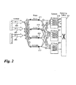
- IP packets from ingress interfaces 205, 207, 209 are associated with their originating ingress interface, which is accomplished by storing an identifier for the ingress interface associated with each IP packet as it moves through the flows. This is illustrated conceptually by numbered circles (1), (2), (3) on the curved arrows representing the packets as they move through the router.
- the numbered circles (1), (2), (3) represent the stored ingress interface identifiers which are associated with the IP packets as they move through flows 211, 213, 215, 217. Each flow handles all of the IP packets associated with a destination IP address.
- IP packets are forwarded from flows 211, 213, 215, 217 to queue sets 219, 221, 223 be reading the stored ingress interface identifier associated with each IP packet.
- Queues 225, 227, 229 within queue set 219 are each configured to handle traffic with different priorities. The queues are processed according to the down stream bandwidth through the switching fabric 231.
- Fig. 3 illustrates an embodiment of the present invention in which the ingress interface identifier is stored in a register 301.
- Network processor 303 has multiple memory blocks 305, 307, 309, each dedicated to one flow, thereby allowing multiple flows to be processed simultaneously. IP packets are processed through each flow, one packet at a time.
- Registers 301, 311, 313 are assigned to flow 305, and remain associated with flow during the time that the packet is being processed within the flow.
- the ingress interface identifier corresponding to each packet is stored in external memory and associated with the packet explicitly for the duration that the packet is being processed by the flow.
- Fig. 4 illustrates another embodiment wherein IP packets that are routable get pre-pended with switching fabric encapsulation headers.
- each IP packet 401 is pre-pended with an encapsulation header 403, into which the ingress interface identifier corresponding to the packet is stored.
- This provides a portable storage mechanism for the ingress interface information.
- Internal field markings within the encapsulation header can be used for additional processing.
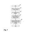
- Fig. 5 illustrates steps of an embodiment of a method of the present invention which starts at step 501.
- the network processor of the IP router receives an IP packet from an ingress interface.
- the Network Processor stores the ingress interface identifier for the interface in which the packet was received.
- the processor can store the ingress interface identifier in a number of different ways as discussed previously. Other methods for storing the ingress interface identifier for each packet are also contemplated as would be well understood by persons skilled in the art.
- the IP packet is directed to a flow corresponding to the destination address of the IP packet.
- the stored identifier is then available for step 509 where the IP packet is forwarded to the queue associated with the ingress interface according to stored identifier. At this point, the identifier is no longer required. In the case of the identifier being stored in an encapsulation header, the header is stripped off after retrieving the identifier.
- IP router and carrying IP packets.
- Other embodiments contemplated within the scope of the present invention apply generally to packet routers carrying data packets and also to Ethernet routers, carrying Ethernet packets having destination MAC addresses and to Label Switched Routers (LSR) carrying MultiProtocol Label Switching (MPLS) packets having MPLS labels as destination addresses.
- LSR Label Switched Routers
- MPLS MultiProtocol Label Switching
- embodiments of the present invention use a single flow for each destination route
- program storage devices e.g., digital data storage media, which are machine or computer-readable and encode machine-executable or computer-executable programs of instructions, wherein said instructions perform some or all of the steps of said above-described methods.
- the program storage devices may be, e.g., digital memories, magnetic storage media such as a magnetic disks and magnetic tapes, hard drives, or optically readable digital data storage media.
- the embodiments are also intended to cover computers programmed to perform said steps of the above-described methods.
- processors may be provided through the use of dedicated hardware as well as hardware capable of executing software in association with appropriate software.
- the functions may be provided by a single dedicated processor, by a single shared processor, or by a plurality of individual processors, some of which may be shared.
- explicit use of the term "processor” or “controller” should not be construed to refer exclusively to hardware capable of executing software, and may implicitly include, without limitation, digital signal processor (DSP) hardware, network processor, application specific integrated circuit (ASIC), field programmable gate array (FPGA), read only memory (ROM) for storing software, random access memory (RAM), and non volatile storage.
- DSP digital signal processor
- ASIC application specific integrated circuit
- FPGA field programmable gate array
- ROM read only memory
- RAM random access memory
- any switches shown in the Figures are conceptual only. Their function may be carried out through the operation of program logic, through dedicated logic, through the interaction of program control and dedicated logic, or even manually, the particular technique being selectable by the implementer as more specifically understood from the context.
- any block diagrams herein represent conceptual views of illustrative circuitry embodying the principles of the invention.
- any flow charts, flow diagrams, state transition diagrams, pseudo code, and the like represent various processes which may be substantially represented in computer readable medium and so executed by a computer or processor, whether or not such computer or processor is explicitly shown.
Description
- The invention is directed to packet switching communication networks, and more particularly, to queuing techniques in access routers.
- In network processor-based Internet Protocol (IP) routers, queuing functionality of traffic management is usually carried out per destination interface. When source-based queuing is required in the router, such as when the router is used at the customer edge and ports are connected to the access side, known solutions define flows per source interface and per destination route in order to associate the queues with the source interface. A flow is a stream of data with the same traffic management characteristics such as a destination IP route (e.g.: 2.2.2.2/24, representing a group of IP addresses having the first 24 bits in common) or a specific destination IP address (e.g.: 1.1.1.1) or destination MAC address in VPLS (Virtual Private LAN Service, RFC2547) or MPLS label in the LSR (Label Switch Router, RFC3032).
- Another known alternative is to have routing data path lookups performed after source based queuing. Both approaches require flows per sources and per destination. Performing queuing functionality per source typically requires significant resources as flows per source need to be created for each destination, resulting in a large context table in memory and therefore consuming large amounts of memory which can be expensive, either in terms of the cost of the memory or reduced performance as memory resources are exhausted in use.
-
Figure 1 illustrates any prior art source base queuing implementation With reference to figure oneports more ingress interfaces example IP packets ingress interfaces IP packets ingress interface 105 are forwarded toqueue set 131. Queues 133, 135, 137 withinqueue set 131 are each configured to handle traffic with different priorities. The queues are processed according to the down stream bandwidth through the switchingfabric 139. -
US 2003/0081624 A1 disclose systems for improved quality of service and traffic management in network routers and other devices requiring a separate flow for each destination route and each ingress interface. - H. Tang and I. Lambadaris disclose in "Novel Bandwidth Allocation Scheme for Ring Networks with Spatial Reuse", 2002, pages 162-169, in Metro and Access Networks II, Wanyi Gu, Cederic F. Lam, Yuan-Hoa Lin, Editors, Proceedings of SPIE Vol. 4908 (2002) © 2002 SPIE 0277-786X/02 a bandwidth allocation scheme for ring networks with spatial reuse that can prevent starvation and maximize the throughput with low complexity, wherein for every node of the ring a separate queue is provided for each source that shares the output link of the particular node.
- H. Tang and I. Lambadaris disclose in "Performance Evaluation of a New Fairness Control Scheme for Ring Networks with Spatial Reusese", 2003, pages 143-153, in Performance and Control of Next-Generation Communication Networks, Robert D. van der Mei, Frank Huebner, Editors, Proceedings of SPIE Vol. 5244 (2003) © 2003 SPIE 0277-786X/03 disclose an approach that provides a separate fair access to all nodes and features low complexity, wherein within each node a separate queue is allocated for every upstream node.
- Therefore, a means of minimizing memory usage while maintaining routing and queuing performance remains highly desirable.
- The object of the present invention is achieved with the method for selecting queues in a packet router with the features of
claim 1. In one embodiment, the invention provides a method for selecting queues in a packet router. The method comprises steps of: receiving a data packet from an ingress interface; storing an identifier for said ingress interface associated with said data packet in said flow; directing said data packet to a flow according to the destination address of said data packet; forwarding said data packet from said flow to a set of queues associated with said ingress interface according to the stored identifier. - Other embodiments further comprise a step of assigning said data packet to a queue within said set of queues according to a priority of said data packet wherein said queue corresponds to said priority.
- In other embodiments the step of storing said identifier comprises storing said identifier in an internal register allocated to said data packet within said flow.
- In other embodiments the step of storing said identifier comprises storing said identifier in external memory allocated to said data packet within said flow.
- In other embodiments the step of storing said identifier comprises pre-pending said identifier to said data packet in an encapsulation header.
- In other embodiments the priority is defined by a Quality of Service (QoS) parameter in said data packet.
- In other embodiments the priority is defined by a forwarding class parameter in said data packet.
- In other embodiments the internal register allocated to said flow while said data packet is present within said flow.
- In other embodiments the destination address comprises a range of destination addresses.
- In other embodiments the packet router comprises an IP router and said data packet comprises an Internet Protocol (IP) packet.
- In other embodiments the packet router comprises an Ethernet router, said data packet comprises an Ethernet packet and said destination address comprises a destination MAC address.
- In other embodiments the packet router comprises a Label Switched Router (LSR) and said data packet comprises a MultiProtocol Label Switching (MPLS) packet and said destination address comprises an MPLS label.
- Another aspect of embodiments of the present invention provide a system for processing incoming packets in a packet router. The system comprises: an ingress interface for receiving a data packet, the ingress interface having an ingress interface identifier; a storing means for storing said ingress interface identifier in association with said data packet in said flow; a flow for accepting said data packet from said interface; wherein said flow is associated with a destination address of said data packet; a forwarding means for forwarding said data packet from said flow to a set of queues associated with said ingress interface according to the stored identifier.
- In some embodiments the forwarding means is configured to assign said data packet to a queue within said set of queues according to a priority of said data packet wherein said queue corresponds to said priority.
- In some embodiments the storing means comprises an internal register allocated to said data packet within said flow.
- In some embodiments the storing means comprises an external memory allocated to said data packet within said flow.
- In some embodiments the storing means comprises an encapsulation header pre-pended to said data packet.
- In some embodiments the system comprises a Network Processor.
- In some embodiments the system comprises a Field Programmable Gate Array.
- In some embodiments the system comprises an Application Specific Integrated Circuit.
- In some embodiments the packet router comprises an IP router and said data packet comprises an Internet Protocol (IP) packet.
- In some embodiments the packet router comprises an Ethernet router, said data packet comprises an Ethernet packet and said destination address comprises a destination MAC address.
- In some embodiments the packet router comprises a Label Switched Router (LSR) and said data packet comprises a Multiprotocol Label Switching (MPLS) packet and said destination address comprises an MPLS label.
- Yet another aspect of embodiments of the present invention provide a program storage device readable by a machine, tangibly embodying a program of instructions executable by the machine to perform method steps described above.
- Some embodiments of apparatus and/or methods in accordance with embodiments of the present invention are now described, by way of example only, and with reference to the accompanying drawings in which:
-
Fig. 1 illustrates a diagrammatic view showing a prior art implementation of source-based queuing in an IP router; -
Fig. 2 illustrates a diagrammatic view showing source-based queuing in an IP router in accordance with an embodiment of the present invention; -
Fig. 3 illustrates aspects of an internal register embodiment the present invention; -
Fig. 4 illustrates a packet encapsulation embodiment of the present invention; and -
Fig. 5 illustrates steps of an embodiment of a method of the present invention. - In the figures like features are denoted by like reference characters.
- In a network processor-based service router, each local IP interface (IF) is bound to a port on an ingress interface card. Incoming IP packets are parsed/classified using network processor filters based on the IP destination address. Packets then undergo IP routing processing on a network processor.
- One embodiment comprises storing the source interface information in a storage register associated with the data packet being processed by the network processor. When the packet has been routed, the packet is then sent to the queue set associated with the interface identified by the source interface information stored in the register. In this embodiment, the register is only associated with the packet currently being processed. When the packet arrives at the queue set associated with the appropriate interface, the packet is added to the queue within the queue set, associated with the priority of the packet. The priority of the packet can be defined by Quality of Service (QoS) parameter within the packet, forwarding class (FC) based on the DSCP of the IP packet and ingress IP I/F policy, or other prioritizing mechanism well known to persons of skill in the art.
- With reference to
Fig. 2 , IP packets fromingress interfaces flows flows Queues fabric 231. -
Fig. 3 illustrates an embodiment of the present invention in which the ingress interface identifier is stored in aregister 301. Network processor 303 has multiple memory blocks 305, 307, 309, each dedicated to one flow, thereby allowing multiple flows to be processed simultaneously. IP packets are processed through each flow, one packet at a time.Registers - In another embodiment, the ingress interface identifier corresponding to each packet is stored in external memory and associated with the packet explicitly for the duration that the packet is being processed by the flow.
-
Fig. 4 , illustrates another embodiment wherein IP packets that are routable get pre-pended with switching fabric encapsulation headers. Thus eachIP packet 401 is pre-pended with anencapsulation header 403, into which the ingress interface identifier corresponding to the packet is stored. This provides a portable storage mechanism for the ingress interface information. Internal field markings within the encapsulation header can be used for additional processing. -
Fig. 5 illustrates steps of an embodiment of a method of the present invention which starts atstep 501. Atstep 503 the network processor of the IP router receives an IP packet from an ingress interface. Atstep 505 the Network Processor stores the ingress interface identifier for the interface in which the packet was received. The processor can store the ingress interface identifier in a number of different ways as discussed previously. Other methods for storing the ingress interface identifier for each packet are also contemplated as would be well understood by persons skilled in the art. Atstep 507 the IP packet is directed to a flow corresponding to the destination address of the IP packet. The stored identifier is then available forstep 509 where the IP packet is forwarded to the queue associated with the ingress interface according to stored identifier. At this point, the identifier is no longer required. In the case of the identifier being stored in an encapsulation header, the header is stripped off after retrieving the identifier. - Note that the preceding description discusses embodiments having an IP router and carrying IP packets. Other embodiments contemplated within the scope of the present invention apply generally to packet routers carrying data packets and also to Ethernet routers, carrying Ethernet packets having destination MAC addresses and to Label Switched Routers (LSR) carrying MultiProtocol Label Switching (MPLS) packets having MPLS labels as destination addresses.
- In contrast to prior art approaches of source-based routing, requiring a separate flow for each destination route and each ingress interface, embodiments of the present invention use a single flow for each destination route
- To illustrate the value of the present invention, consider an IP router having 100 (one hundred) ingress interfaces requiring source-based queuing and 1000 (one thousand) different destination routes or destination addresses. Using a prior art implementation having one flow per ingress interface and per destination route, this would require 100,000 separate flows, whereas embodiments of the present invention would only require 100 flows. In an embodiment using an internal register to store the ingress interface identifier, it would also require one internal register per flow. In typical network processor implementations, each flow would typically have several unused registers assigned and available anyway.
- A person of skill in the art would readily recognize that steps of various above-described methods can be performed by programmed computers. Herein, some embodiments are also intended to cover program storage devices, e.g., digital data storage media, which are machine or computer-readable and encode machine-executable or computer-executable programs of instructions, wherein said instructions perform some or all of the steps of said above-described methods. The program storage devices may be, e.g., digital memories, magnetic storage media such as a magnetic disks and magnetic tapes, hard drives, or optically readable digital data storage media. The embodiments are also intended to cover computers programmed to perform said steps of the above-described methods.
- The description and drawings merely illustrate the principles of the invention. It will thus be appreciated that those skilled in the art will be able to devise various arrangements that, although not explicitly described or shown herein, embody the principles of the invention and are included within its scope defined by the claims. Furthermore, all examples recited herein are principally intended expressly to be only for pedagogical purposes to aid the reader in understanding the principles of the invention and the concepts contributed by the inventor(s) to furthering the art, and are to be construed as being without limitation to such specifically recited examples and conditions. Moreover, all statements herein reciting principles, aspects, and embodiments of the invention, as well as specific examples thereof, are intended to encompass equivalents thereof.
- The functions of the various elements shown in the Figures, including any functional blocks labeled as "processors", may be provided through the use of dedicated hardware as well as hardware capable of executing software in association with appropriate software. When provided by a processor, the functions may be provided by a single dedicated processor, by a single shared processor, or by a plurality of individual processors, some of which may be shared. Moreover, explicit use of the term "processor" or "controller" should not be construed to refer exclusively to hardware capable of executing software, and may implicitly include, without limitation, digital signal processor (DSP) hardware, network processor, application specific integrated circuit (ASIC), field programmable gate array (FPGA), read only memory (ROM) for storing software, random access memory (RAM), and non volatile storage. Other hardware, conventional and/or custom, may also be included. Similarly, any switches shown in the Figures are conceptual only. Their function may be carried out through the operation of program logic, through dedicated logic, through the interaction of program control and dedicated logic, or even manually, the particular technique being selectable by the implementer as more specifically understood from the context.
- It should be appreciated by those skilled in the art that any block diagrams herein represent conceptual views of illustrative circuitry embodying the principles of the invention. Similarly, it will be appreciated that any flow charts, flow diagrams, state transition diagrams, pseudo code, and the like represent various processes which may be substantially represented in computer readable medium and so executed by a computer or processor, whether or not such computer or processor is explicitly shown.
- Numerous modifications, variations and adaptations may be made to the embodiment of the invention described above without departing from the scope of the invention, which is defined in the claims.
Claims (10)
- A method for selecting queues in a packet router, the method comprising steps of:receiving a data packet from an ingress interface (205, 207, 209);storing an identifier for said ingress interface (205, 207, 209) associated with said received data packet in a flow;directing said received data packet to the flow (211, 213, 215, 217) according to the destination address of said received data packet; andforwarding said directed data packet from said flow (211, 213, 215, 217) to a set of queues (219, 221, 223) associated with said ingress interface (205, 207, 209) according to the stored identifiercharacterized inthat a single flow respectively corresponds to each destination address of received data packets.
- The method of claim 1,
further comprising a step of assigning said data packet to a queue within said set of queues (219, 221, 223) according to a priority of said data packet wherein said queue corresponds to said priority. - The method of claim 1,
wherein said step of storing said identifier comprises storing said identifier in an internal register (301,311,313) allocated to said data packet within said flow. - The method of claim 1,
wherein said step of storing said identifier comprises pre-pending said identifier to said data packet in an encapsulation header (403). - The method of claim 1,
wherein said priority is defined by a Quality of Service, QoS, parameter in said data packet. - The method of claim 3,
wherein said internal register (301, 311, 313) is allocated to said flow while said data packet is present within said flow. - The method of claim 1,
wherein said destination address comprises a range of destination addresses. - The method of claim 1,
wherein said packet router comprises an IP router and said data packet comprises an Internet Protocol, IP, packet. - The method of claim 1,
wherein said packet router comprises an Ethernet router, said data packet comprises an Ethernet packet and said destination address comprises a destination Media Access Control, MAC, address. - The method of claim 1,
wherein said packet router comprises a Label Switched Router, LSR, and said data packet comprises a MultiProtocol Label Switching, MPLS, packet and said destination address comprises an MPLS label.
Applications Claiming Priority (2)
| Application Number | Priority Date | Filing Date | Title |
|---|---|---|---|
| US12/659,032 US9853904B2 (en) | 2010-02-23 | 2010-02-23 | Source-based queue selection mechanism in the routing environment |
| PCT/IB2011/000472 WO2011104628A1 (en) | 2010-02-23 | 2011-02-07 | Source based queue selection mechanism in the routing environment |
Publications (2)
| Publication Number | Publication Date |
|---|---|
| EP2540040A1 EP2540040A1 (en) | 2013-01-02 |
| EP2540040B1 true EP2540040B1 (en) | 2015-04-01 |
Family
ID=44146530
Family Applications (1)
| Application Number | Title | Priority Date | Filing Date |
|---|---|---|---|
| EP11719369.8A Not-in-force EP2540040B1 (en) | 2010-02-23 | 2011-02-07 | Source based queue selection mechanism in the routing environment |
Country Status (6)
| Country | Link |
|---|---|
| US (1) | US9853904B2 (en) |
| EP (1) | EP2540040B1 (en) |
| JP (1) | JP5468146B2 (en) |
| KR (1) | KR101445466B1 (en) |
| CN (1) | CN102763383B (en) |
| WO (1) | WO2011104628A1 (en) |
Families Citing this family (1)
| Publication number | Priority date | Publication date | Assignee | Title |
|---|---|---|---|---|
| KR101803332B1 (en) * | 2016-01-12 | 2017-12-01 | 쿨클라우드(주) | Network system for internet of things |
Family Cites Families (19)
| Publication number | Priority date | Publication date | Assignee | Title |
|---|---|---|---|---|
| DE4432061C1 (en) * | 1994-09-09 | 1995-12-07 | Philips Patentverwaltung | Packet data transmission system with input number generation circuits |
| US6570876B1 (en) * | 1998-04-01 | 2003-05-27 | Hitachi, Ltd. | Packet switch and switching method for switching variable length packets |
| JP3859369B2 (en) * | 1998-09-18 | 2006-12-20 | 株式会社東芝 | Message relay apparatus and method |
| JP3397173B2 (en) | 1999-06-07 | 2003-04-14 | 日本電気株式会社 | Packet switching device, switch control method therefor, and storage medium storing switch control program |
| US6975638B1 (en) * | 2000-10-13 | 2005-12-13 | Force10 Networks, Inc. | Interleaved weighted fair queuing mechanism and system |
| US6973093B1 (en) * | 2000-12-29 | 2005-12-06 | Cisco Technology, Inc. | Switching fabric for interfacing a host processor and a plurality of network modules |
| US7035212B1 (en) * | 2001-01-25 | 2006-04-25 | Optim Networks | Method and apparatus for end to end forwarding architecture |
| US6847645B1 (en) * | 2001-02-22 | 2005-01-25 | Cisco Technology, Inc. | Method and apparatus for controlling packet header buffer wrap around in a forwarding engine of an intermediate network node |
| WO2002069575A1 (en) * | 2001-02-28 | 2002-09-06 | Gotham Networks, Inc. | Methods and apparatus for network routing device |
| EP1416681A1 (en) * | 2002-10-29 | 2004-05-06 | Alcatel | Method for traffic engineering and ingress router adapted to perform such a method |
| US7570654B2 (en) * | 2003-12-22 | 2009-08-04 | Intel Corporation | Switching device utilizing requests indicating cumulative amount of data |
| JP2006094304A (en) | 2004-09-27 | 2006-04-06 | Nec Commun Syst Ltd | Transmission band control method and transmission band control system |
| US7620046B2 (en) * | 2004-09-30 | 2009-11-17 | Intel Corporation | Dynamically assigning packet flows |
| GB2422272A (en) * | 2005-01-14 | 2006-07-19 | King S College London | Network mobility |
| GB2430581B (en) * | 2005-09-21 | 2010-03-10 | King S College London | Access router selection method |
| US7760735B1 (en) * | 2007-02-06 | 2010-07-20 | Google Inc. | Method and system for discovering network paths |
| CN101350942A (en) * | 2007-07-19 | 2009-01-21 | 中国移动通信集团公司 | System and method for transmitting multimedia information as well as multimedia information service gateway |
| CN101478703A (en) * | 2008-12-12 | 2009-07-08 | 北京邮电大学 | Implementation method for T-MPLS optical transmission network multi-service node |
| US8571049B2 (en) * | 2009-11-24 | 2013-10-29 | Verizon Patent And Licensing, Inc. | Setting and changing queue sizes in line cards |
-
2010
- 2010-02-23 US US12/659,032 patent/US9853904B2/en active Active
-
2011
- 2011-02-07 JP JP2012554442A patent/JP5468146B2/en not_active Expired - Fee Related
- 2011-02-07 WO PCT/IB2011/000472 patent/WO2011104628A1/en active Application Filing
- 2011-02-07 KR KR1020127021983A patent/KR101445466B1/en not_active IP Right Cessation
- 2011-02-07 CN CN201180008559.3A patent/CN102763383B/en not_active Expired - Fee Related
- 2011-02-07 EP EP11719369.8A patent/EP2540040B1/en not_active Not-in-force
Also Published As
| Publication number | Publication date |
|---|---|
| US9853904B2 (en) | 2017-12-26 |
| JP5468146B2 (en) | 2014-04-09 |
| EP2540040A1 (en) | 2013-01-02 |
| JP2013526096A (en) | 2013-06-20 |
| KR20120120342A (en) | 2012-11-01 |
| KR101445466B1 (en) | 2014-09-26 |
| CN102763383B (en) | 2015-11-25 |
| US20110206046A1 (en) | 2011-08-25 |
| WO2011104628A1 (en) | 2011-09-01 |
| CN102763383A (en) | 2012-10-31 |
Similar Documents
| Publication | Publication Date | Title |
|---|---|---|
| US7953885B1 (en) | Method and apparatus to apply aggregate access control list/quality of service features using a redirect cause | |
| EP1480380B1 (en) | Data mirroring | |
| CN106453138B (en) | Message processing method and device | |
| EP1569389A1 (en) | Communication device and band control method | |
| US11233732B2 (en) | Label management method, data stream processing method, and device | |
| EP1588530A2 (en) | Method and device for the classification and redirection of data packets in a heterogeneous network | |
| EP3094053A1 (en) | Predictive egress packet classification for quality of service | |
| US10110487B1 (en) | Signaling priority information for encapsulated packets | |
| US20210152473A1 (en) | Method and system for propagating network traffic flows between end points based on service and priority policies | |
| JP4758476B2 (en) | Arbitration method in an integrated circuit and a network on the integrated circuit | |
| US7889739B2 (en) | Label and exp field based MPLS network device | |
| US10764177B2 (en) | Efficient implementation of complex network segmentation | |
| EP2540040B1 (en) | Source based queue selection mechanism in the routing environment | |
| JP3610913B2 (en) | Router, packet switching method, and packet switching program | |
| KR101302410B1 (en) | Packet flood control | |
| US20120106555A1 (en) | Low latency carrier class switch-router | |
| US7061919B1 (en) | System and method for providing multiple classes of service in a packet switched network | |
| WO2010077504A1 (en) | Mobility management using address pools in mobility label based mpls networks | |
| Cisco | Configuring Quality of Service | |
| Cisco | Configuring Quality of Service | |
| WO2015028563A1 (en) | Quality of service mapping in networks | |
| Zhang et al. | A qos-oriented network architecture based on virtualization | |
| US8295172B1 (en) | Network device traffic class mapping function | |
| CN117527668A (en) | Data transmission method, device, network equipment and storage medium | |
| Viriyaphol et al. | A study of routing with a clue versus label switching over IP based networks |
Legal Events
| Date | Code | Title | Description |
|---|---|---|---|
| PUAI | Public reference made under article 153(3) epc to a published international application that has entered the european phase |
Free format text: ORIGINAL CODE: 0009012 |
|
| 17P | Request for examination filed |
Effective date: 20120924 |
|
| AK | Designated contracting states |
Kind code of ref document: A1 Designated state(s): AL AT BE BG CH CY CZ DE DK EE ES FI FR GB GR HR HU IE IS IT LI LT LU LV MC MK MT NL NO PL PT RO RS SE SI SK SM TR |
|
| DAX | Request for extension of the european patent (deleted) | ||
| 111Z | Information provided on other rights and legal means of execution |
Free format text: AL AT BE BG CH CY CZ DE DK EE ES FI FR GB GR HR HU IE IS IT LI LT LU LV MC MK MT NL NO PL PT RO RS SE SI SK SM TR Effective date: 20130410 |
|
| 17Q | First examination report despatched |
Effective date: 20131204 |
|
| RAP1 | Party data changed (applicant data changed or rights of an application transferred) |
Owner name: ALCATEL LUCENT |
|
| REG | Reference to a national code |
Ref country code: DE Ref legal event code: R079 Ref document number: 602011015235 Country of ref document: DE Free format text: PREVIOUS MAIN CLASS: H04L0012560000 Ipc: H04L0012700000 |
|
| RIC1 | Information provided on ipc code assigned before grant |
Ipc: H04L 12/70 20130101AFI20140902BHEP |
|
| GRAP | Despatch of communication of intention to grant a patent |
Free format text: ORIGINAL CODE: EPIDOSNIGR1 |
|
| INTG | Intention to grant announced |
Effective date: 20141014 |
|
| D11X | Information provided on other rights and legal means of execution (deleted) | ||
| GRAS | Grant fee paid |
Free format text: ORIGINAL CODE: EPIDOSNIGR3 |
|
| GRAA | (expected) grant |
Free format text: ORIGINAL CODE: 0009210 |
|
| AK | Designated contracting states |
Kind code of ref document: B1 Designated state(s): AL AT BE BG CH CY CZ DE DK EE ES FI FR GB GR HR HU IE IS IT LI LT LU LV MC MK MT NL NO PL PT RO RS SE SI SK SM TR |
|
| REG | Reference to a national code |
Ref country code: GB Ref legal event code: FG4D |
|
| REG | Reference to a national code |
Ref country code: CH Ref legal event code: EP |
|
| REG | Reference to a national code |
Ref country code: IE Ref legal event code: FG4D |
|
| REG | Reference to a national code |
Ref country code: DE Ref legal event code: R096 Ref document number: 602011015235 Country of ref document: DE Effective date: 20150513 |
|
| REG | Reference to a national code |
Ref country code: AT Ref legal event code: REF Ref document number: 719659 Country of ref document: AT Kind code of ref document: T Effective date: 20150515 |
|
| REG | Reference to a national code |
Ref country code: NL Ref legal event code: VDEP Effective date: 20150401 |
|
| REG | Reference to a national code |
Ref country code: AT Ref legal event code: MK05 Ref document number: 719659 Country of ref document: AT Kind code of ref document: T Effective date: 20150401 |
|
| REG | Reference to a national code |
Ref country code: LT Ref legal event code: MG4D |
|
| PG25 | Lapsed in a contracting state [announced via postgrant information from national office to epo] |
Ref country code: NL Free format text: LAPSE BECAUSE OF FAILURE TO SUBMIT A TRANSLATION OF THE DESCRIPTION OR TO PAY THE FEE WITHIN THE PRESCRIBED TIME-LIMIT Effective date: 20150401 |
|
| PG25 | Lapsed in a contracting state [announced via postgrant information from national office to epo] |
Ref country code: HR Free format text: LAPSE BECAUSE OF FAILURE TO SUBMIT A TRANSLATION OF THE DESCRIPTION OR TO PAY THE FEE WITHIN THE PRESCRIBED TIME-LIMIT Effective date: 20150401 Ref country code: NO Free format text: LAPSE BECAUSE OF FAILURE TO SUBMIT A TRANSLATION OF THE DESCRIPTION OR TO PAY THE FEE WITHIN THE PRESCRIBED TIME-LIMIT Effective date: 20150701 Ref country code: LT Free format text: LAPSE BECAUSE OF FAILURE TO SUBMIT A TRANSLATION OF THE DESCRIPTION OR TO PAY THE FEE WITHIN THE PRESCRIBED TIME-LIMIT Effective date: 20150401 Ref country code: PT Free format text: LAPSE BECAUSE OF FAILURE TO SUBMIT A TRANSLATION OF THE DESCRIPTION OR TO PAY THE FEE WITHIN THE PRESCRIBED TIME-LIMIT Effective date: 20150803 Ref country code: FI Free format text: LAPSE BECAUSE OF FAILURE TO SUBMIT A TRANSLATION OF THE DESCRIPTION OR TO PAY THE FEE WITHIN THE PRESCRIBED TIME-LIMIT Effective date: 20150401 Ref country code: CZ Free format text: LAPSE BECAUSE OF FAILURE TO SUBMIT A TRANSLATION OF THE DESCRIPTION OR TO PAY THE FEE WITHIN THE PRESCRIBED TIME-LIMIT Effective date: 20150401 Ref country code: ES Free format text: LAPSE BECAUSE OF FAILURE TO SUBMIT A TRANSLATION OF THE DESCRIPTION OR TO PAY THE FEE WITHIN THE PRESCRIBED TIME-LIMIT Effective date: 20150401 |
|
| PG25 | Lapsed in a contracting state [announced via postgrant information from national office to epo] |
Ref country code: RS Free format text: LAPSE BECAUSE OF FAILURE TO SUBMIT A TRANSLATION OF THE DESCRIPTION OR TO PAY THE FEE WITHIN THE PRESCRIBED TIME-LIMIT Effective date: 20150401 Ref country code: AT Free format text: LAPSE BECAUSE OF FAILURE TO SUBMIT A TRANSLATION OF THE DESCRIPTION OR TO PAY THE FEE WITHIN THE PRESCRIBED TIME-LIMIT Effective date: 20150401 Ref country code: GR Free format text: LAPSE BECAUSE OF FAILURE TO SUBMIT A TRANSLATION OF THE DESCRIPTION OR TO PAY THE FEE WITHIN THE PRESCRIBED TIME-LIMIT Effective date: 20150702 Ref country code: LV Free format text: LAPSE BECAUSE OF FAILURE TO SUBMIT A TRANSLATION OF THE DESCRIPTION OR TO PAY THE FEE WITHIN THE PRESCRIBED TIME-LIMIT Effective date: 20150401 Ref country code: IS Free format text: LAPSE BECAUSE OF FAILURE TO SUBMIT A TRANSLATION OF THE DESCRIPTION OR TO PAY THE FEE WITHIN THE PRESCRIBED TIME-LIMIT Effective date: 20150801 |
|
| REG | Reference to a national code |
Ref country code: DE Ref legal event code: R097 Ref document number: 602011015235 Country of ref document: DE |
|
| PG25 | Lapsed in a contracting state [announced via postgrant information from national office to epo] |
Ref country code: DK Free format text: LAPSE BECAUSE OF FAILURE TO SUBMIT A TRANSLATION OF THE DESCRIPTION OR TO PAY THE FEE WITHIN THE PRESCRIBED TIME-LIMIT Effective date: 20150401 Ref country code: EE Free format text: LAPSE BECAUSE OF FAILURE TO SUBMIT A TRANSLATION OF THE DESCRIPTION OR TO PAY THE FEE WITHIN THE PRESCRIBED TIME-LIMIT Effective date: 20150401 |
|
| PLBE | No opposition filed within time limit |
Free format text: ORIGINAL CODE: 0009261 |
|
| STAA | Information on the status of an ep patent application or granted ep patent |
Free format text: STATUS: NO OPPOSITION FILED WITHIN TIME LIMIT |
|
| REG | Reference to a national code |
Ref country code: FR Ref legal event code: PLFP Year of fee payment: 6 |
|
| PG25 | Lapsed in a contracting state [announced via postgrant information from national office to epo] |
Ref country code: PL Free format text: LAPSE BECAUSE OF FAILURE TO SUBMIT A TRANSLATION OF THE DESCRIPTION OR TO PAY THE FEE WITHIN THE PRESCRIBED TIME-LIMIT Effective date: 20150401 Ref country code: SK Free format text: LAPSE BECAUSE OF FAILURE TO SUBMIT A TRANSLATION OF THE DESCRIPTION OR TO PAY THE FEE WITHIN THE PRESCRIBED TIME-LIMIT Effective date: 20150401 Ref country code: RO Free format text: LAPSE BECAUSE OF NON-PAYMENT OF DUE FEES Effective date: 20150401 |
|
| 26N | No opposition filed |
Effective date: 20160105 |
|
| PG25 | Lapsed in a contracting state [announced via postgrant information from national office to epo] |
Ref country code: IT Free format text: LAPSE BECAUSE OF FAILURE TO SUBMIT A TRANSLATION OF THE DESCRIPTION OR TO PAY THE FEE WITHIN THE PRESCRIBED TIME-LIMIT Effective date: 20150401 |
|
| PG25 | Lapsed in a contracting state [announced via postgrant information from national office to epo] |
Ref country code: BE Free format text: LAPSE BECAUSE OF NON-PAYMENT OF DUE FEES Effective date: 20160229 Ref country code: SI Free format text: LAPSE BECAUSE OF FAILURE TO SUBMIT A TRANSLATION OF THE DESCRIPTION OR TO PAY THE FEE WITHIN THE PRESCRIBED TIME-LIMIT Effective date: 20150401 |
|
| PG25 | Lapsed in a contracting state [announced via postgrant information from national office to epo] |
Ref country code: BE Free format text: LAPSE BECAUSE OF FAILURE TO SUBMIT A TRANSLATION OF THE DESCRIPTION OR TO PAY THE FEE WITHIN THE PRESCRIBED TIME-LIMIT Effective date: 20150401 |
|
| PG25 | Lapsed in a contracting state [announced via postgrant information from national office to epo] |
Ref country code: LU Free format text: LAPSE BECAUSE OF FAILURE TO SUBMIT A TRANSLATION OF THE DESCRIPTION OR TO PAY THE FEE WITHIN THE PRESCRIBED TIME-LIMIT Effective date: 20160207 Ref country code: MC Free format text: LAPSE BECAUSE OF FAILURE TO SUBMIT A TRANSLATION OF THE DESCRIPTION OR TO PAY THE FEE WITHIN THE PRESCRIBED TIME-LIMIT Effective date: 20150401 |
|
| REG | Reference to a national code |
Ref country code: CH Ref legal event code: PL |
|
| PG25 | Lapsed in a contracting state [announced via postgrant information from national office to epo] |
Ref country code: LI Free format text: LAPSE BECAUSE OF NON-PAYMENT OF DUE FEES Effective date: 20160229 Ref country code: CH Free format text: LAPSE BECAUSE OF NON-PAYMENT OF DUE FEES Effective date: 20160229 |
|
| REG | Reference to a national code |
Ref country code: IE Ref legal event code: MM4A |
|
| PG25 | Lapsed in a contracting state [announced via postgrant information from national office to epo] |
Ref country code: IE Free format text: LAPSE BECAUSE OF NON-PAYMENT OF DUE FEES Effective date: 20160207 |
|
| REG | Reference to a national code |
Ref country code: FR Ref legal event code: PLFP Year of fee payment: 7 |
|
| PGFP | Annual fee paid to national office [announced via postgrant information from national office to epo] |
Ref country code: FR Payment date: 20170217 Year of fee payment: 7 |
|
| PG25 | Lapsed in a contracting state [announced via postgrant information from national office to epo] |
Ref country code: SE Free format text: LAPSE BECAUSE OF FAILURE TO SUBMIT A TRANSLATION OF THE DESCRIPTION OR TO PAY THE FEE WITHIN THE PRESCRIBED TIME-LIMIT Effective date: 20150401 |
|
| PG25 | Lapsed in a contracting state [announced via postgrant information from national office to epo] |
Ref country code: MT Free format text: LAPSE BECAUSE OF FAILURE TO SUBMIT A TRANSLATION OF THE DESCRIPTION OR TO PAY THE FEE WITHIN THE PRESCRIBED TIME-LIMIT Effective date: 20150401 |
|
| PG25 | Lapsed in a contracting state [announced via postgrant information from national office to epo] |
Ref country code: HU Free format text: LAPSE BECAUSE OF FAILURE TO SUBMIT A TRANSLATION OF THE DESCRIPTION OR TO PAY THE FEE WITHIN THE PRESCRIBED TIME-LIMIT; INVALID AB INITIO Effective date: 20110207 Ref country code: SM Free format text: LAPSE BECAUSE OF FAILURE TO SUBMIT A TRANSLATION OF THE DESCRIPTION OR TO PAY THE FEE WITHIN THE PRESCRIBED TIME-LIMIT Effective date: 20150401 Ref country code: CY Free format text: LAPSE BECAUSE OF FAILURE TO SUBMIT A TRANSLATION OF THE DESCRIPTION OR TO PAY THE FEE WITHIN THE PRESCRIBED TIME-LIMIT Effective date: 20150401 |
|
| PG25 | Lapsed in a contracting state [announced via postgrant information from national office to epo] |
Ref country code: TR Free format text: LAPSE BECAUSE OF FAILURE TO SUBMIT A TRANSLATION OF THE DESCRIPTION OR TO PAY THE FEE WITHIN THE PRESCRIBED TIME-LIMIT Effective date: 20150401 Ref country code: MK Free format text: LAPSE BECAUSE OF FAILURE TO SUBMIT A TRANSLATION OF THE DESCRIPTION OR TO PAY THE FEE WITHIN THE PRESCRIBED TIME-LIMIT Effective date: 20150401 Ref country code: MT Free format text: LAPSE BECAUSE OF FAILURE TO SUBMIT A TRANSLATION OF THE DESCRIPTION OR TO PAY THE FEE WITHIN THE PRESCRIBED TIME-LIMIT Effective date: 20160229 |
|
| PG25 | Lapsed in a contracting state [announced via postgrant information from national office to epo] |
Ref country code: BG Free format text: LAPSE BECAUSE OF FAILURE TO SUBMIT A TRANSLATION OF THE DESCRIPTION OR TO PAY THE FEE WITHIN THE PRESCRIBED TIME-LIMIT Effective date: 20150401 |
|
| PG25 | Lapsed in a contracting state [announced via postgrant information from national office to epo] |
Ref country code: AL Free format text: LAPSE BECAUSE OF FAILURE TO SUBMIT A TRANSLATION OF THE DESCRIPTION OR TO PAY THE FEE WITHIN THE PRESCRIBED TIME-LIMIT Effective date: 20150401 |
|
| REG | Reference to a national code |
Ref country code: FR Ref legal event code: ST Effective date: 20181031 |
|
| PG25 | Lapsed in a contracting state [announced via postgrant information from national office to epo] |
Ref country code: FR Free format text: LAPSE BECAUSE OF NON-PAYMENT OF DUE FEES Effective date: 20180228 |
|
| REG | Reference to a national code |
Ref country code: DE Ref legal event code: R082 Ref document number: 602011015235 Country of ref document: DE Representative=s name: MENZIETTI WETZEL, DE Ref country code: DE Ref legal event code: R081 Ref document number: 602011015235 Country of ref document: DE Owner name: PROVENANCE ASSET GROUP LLC, PITTSFORD, US Free format text: FORMER OWNER: ALCATEL LUCENT, BOULOGNE BILLANCOURT, FR |
|
| REG | Reference to a national code |
Ref country code: GB Ref legal event code: 732E Free format text: REGISTERED BETWEEN 20190418 AND 20190426 |
|
| PGFP | Annual fee paid to national office [announced via postgrant information from national office to epo] |
Ref country code: DE Payment date: 20210226 Year of fee payment: 11 Ref country code: GB Payment date: 20210301 Year of fee payment: 11 |
|
| REG | Reference to a national code |
Ref country code: DE Ref legal event code: R119 Ref document number: 602011015235 Country of ref document: DE |
|
| GBPC | Gb: european patent ceased through non-payment of renewal fee |
Effective date: 20220207 |
|
| PG25 | Lapsed in a contracting state [announced via postgrant information from national office to epo] |
Ref country code: GB Free format text: LAPSE BECAUSE OF NON-PAYMENT OF DUE FEES Effective date: 20220207 Ref country code: DE Free format text: LAPSE BECAUSE OF NON-PAYMENT OF DUE FEES Effective date: 20220901 |