EP2093094A1 - Head-up display device - Google Patents
Head-up display device Download PDFInfo
- Publication number
- EP2093094A1 EP2093094A1 EP07829540A EP07829540A EP2093094A1 EP 2093094 A1 EP2093094 A1 EP 2093094A1 EP 07829540 A EP07829540 A EP 07829540A EP 07829540 A EP07829540 A EP 07829540A EP 2093094 A1 EP2093094 A1 EP 2093094A1
- Authority
- EP
- European Patent Office
- Prior art keywords
- user
- infrared ray
- head
- display
- display apparatus
- Prior art date
- Legal status (The legal status is an assumption and is not a legal conclusion. Google has not performed a legal analysis and makes no representation as to the accuracy of the status listed.)
- Granted
Links
Images

Classifications
-
- G—PHYSICS
- G02—OPTICS
- G02B—OPTICAL ELEMENTS, SYSTEMS OR APPARATUS
- G02B27/00—Optical systems or apparatus not provided for by any of the groups G02B1/00 - G02B26/00, G02B30/00
- G02B27/01—Head-up displays
-
- A—HUMAN NECESSITIES
- A61—MEDICAL OR VETERINARY SCIENCE; HYGIENE
- A61B—DIAGNOSIS; SURGERY; IDENTIFICATION
- A61B3/00—Apparatus for testing the eyes; Instruments for examining the eyes
- A61B3/10—Objective types, i.e. instruments for examining the eyes independent of the patients' perceptions or reactions
- A61B3/113—Objective types, i.e. instruments for examining the eyes independent of the patients' perceptions or reactions for determining or recording eye movement
-
- G—PHYSICS
- G02—OPTICS
- G02B—OPTICAL ELEMENTS, SYSTEMS OR APPARATUS
- G02B27/00—Optical systems or apparatus not provided for by any of the groups G02B1/00 - G02B26/00, G02B30/00
- G02B27/01—Head-up displays
- G02B27/0101—Head-up displays characterised by optical features
- G02B2027/0138—Head-up displays characterised by optical features comprising image capture systems, e.g. camera
-
- G—PHYSICS
- G02—OPTICS
- G02B—OPTICAL ELEMENTS, SYSTEMS OR APPARATUS
- G02B27/00—Optical systems or apparatus not provided for by any of the groups G02B1/00 - G02B26/00, G02B30/00
- G02B27/01—Head-up displays
- G02B27/0101—Head-up displays characterised by optical features
- G02B2027/014—Head-up displays characterised by optical features comprising information/image processing systems
-
- G—PHYSICS
- G02—OPTICS
- G02B—OPTICAL ELEMENTS, SYSTEMS OR APPARATUS
- G02B27/00—Optical systems or apparatus not provided for by any of the groups G02B1/00 - G02B26/00, G02B30/00
- G02B27/01—Head-up displays
- G02B27/0149—Head-up displays characterised by mechanical features
- G02B2027/0154—Head-up displays characterised by mechanical features with movable elements
-
- G—PHYSICS
- G02—OPTICS
- G02B—OPTICAL ELEMENTS, SYSTEMS OR APPARATUS
- G02B27/00—Optical systems or apparatus not provided for by any of the groups G02B1/00 - G02B26/00, G02B30/00
- G02B27/01—Head-up displays
- G02B27/0179—Display position adjusting means not related to the information to be displayed
- G02B2027/0187—Display position adjusting means not related to the information to be displayed slaved to motion of at least a part of the body of the user, e.g. head, eye
Definitions
- the present invention relates to a head-up display apparatus configured so that visible light emitted from display means is reflected toward a user by a combiner member, forming a display image, and particularly, to form a structure for accurately calculating an eye position of the user.
- Patent Document 1 Usually, as this kind of head-up display apparatus, one described in Patent Document 1 below has been known. With such a head-up display apparatus, it is also possible to use a combiner, and a reflecting member, of the head-up display apparatus in imaging a user by disposing an imaging device which captures an image of the user in the optical axis of the head-up display apparatus, thereby to reduce the number of dedicated members required for the imaging, captures an image of the user (particularly the user's face) with a simpler configuration, and calculate an eye position of the user.
- Patent Document 1 JP-A-8-156646
- the invention focusing on the previously described problem, has an object of providing a head-up display apparatus having a structure capable of capturing an image of a user and which can accurately calculate the user's eye position.
- the invention being a head-up display apparatus configured so that visible light emitted from display means is reflected toward a user by a combiner member, forming a display image
- infrared ray emitting means which emits an infrared ray toward the user
- a mirror member which reflects the visible light, emitted from the display means, toward the combiner member, and transmits the infrared ray reflected by the user and the combiner member
- a plurality of imaging means which sense the infrared ray transmitted through the mirror member, and each image the user from different directions
- image processing means which calculates the user's eye position based on an image captured by the imaging means.
- the invention is characterized in that the infrared ray emitting means is disposed in such a way as to face the mirror member, and is positioned between the plurality of imaging means.
- the invention is characterized in that a light shielding member is disposed between the infrared ray emitting means and the plurality of imaging means.
- the invention is characterized in that the light shielding member is disposed in such a way as to come into contact with the mirror member.
- the invention is characterized in that the mirror member is configured of a cold mirror.
- the invention is characterized in that the combiner member is configured of a windshield of a vehicle.
- the invention is characterized in that the combiner member is configured of a concave mirror disposed on a dashboard of the vehicle.
- the invention including adjustment means which can adjust a position of formation of the display image, is characterized in that the adjustment means, based on a result of the calculation by the image processing means, adjusts the display image formation position.
- the invention relates to a head-up display apparatus in which visible light emitted from display means is reflected toward a user by a combiner member to form a display image, and has a structure capable of capturing an image of the user, enabling the user's eye position to be accurately calculated.
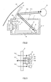
- the head-up display apparatus is configured mainly of a housing 1, display means 2, a cold mirror (a mirror member) 3, a concave mirror (a combiner member) 4, infrared ray emitting means 5, first imaging means 6, second imaging means 7, and image processing means 8.
- a virtual image (a display image) V is formed in such a way as to be positioned at a front of a vehicle (on a windshield W side). Also, with such a head-up display apparatus, as shown in Fig. 1 , by display light (visible light) L emitted from the display means 2 being reflected by the concave mirror 4, and directed to a driver (a user) D, a virtual image (a display image) V is formed in such a way as to be positioned at a front of a vehicle (on a windshield W side). Also, with such a head-up display apparatus, as shown in Fig.
- an infrared ray R1 emitted from the infrared ray emitting means 5 is transmitted through the cold mirror 3, is also reflected by the concave mirror 4, and directed to the driver D, and furthermore, an infrared ray R2 reflected off the driver D is reflected toward the cold mirror 3 by the concave mirror 4, is transmitted through the cold mirror 3, and applied to the first and second imaging means 6 and 7, thereby imaging the driver D (particularly his or her face). Consequently, it is possible to carry out an imaging of the driver D utilizing the optical path of the head-up display apparatus, and to image the driver D with a simpler configuration.
- the display means 2 being disposed in the housing 1, has visible light LED' s 2a, a lens array 2b, a wiring substrate 2c, a heat radiating member 2d, and a liquid crystal display element 2e.
- the visible light LED's 2a such as chip LED's are mounted on a surface of the wiring substrate 2c on the lens array 2b side. Also, the visible light LED's 2a with a low directivity (in the embodiment, 20 to 30 degrees), are respectively provided in each of positions corresponding to spherical surfaces of the lens array 2b. In this case, for the visible light LEDs 2a, two of which glow white are used.
- the lens array 2b being made of a transmissive synthetic resin material (for example, an acrylic resin), is provided in the housing 1.
- the lens array 2b being configured forming a plurality of similar convex spherical surfaces (convexities) corresponding to the individual visible light LED's 2a, causes illumination lights from the visible light LED's 2a to be refracted by the spherical surfaces, enabling a visible light L with evenness to be applied to the liquid crystal display element 2e which is an illuminated member.
- the wiring substrate 2c preferably, an aluminum substrate with a high thermal conductivity, is provided on a rear side of the liquid crystal display element 2e inside the housing 1 in such a way as to be parallel with a predetermined distance to the lens array 2b.
- the wiring substrate 2c on which are mounted electronic parts such as at least the visible light LED's 2a, is provided with wiring for supplying power to the electronic parts.
- the predetermined distance varies depending on the directivity of the visible light LED's 2a and the shape of the spherical surfaces of the lens array 2b, and such a distance as causes less unevenness in luminance is selected.
- the heat radiating member 2d preferably, a metal material with a high thermal conductivity, is disposed in such a way as to come into contact with the wiring substrate 2c, and have one portion thereof exposed outside the housing 1.
- the heat radiating member 2d has a function of radiating heat generated by a drive of the visible light LED's 2a to the exterior.
- the liquid crystal display element 2e is configured so that a color filter having a red layer, a green layer, and a blue layer which are provided depending on a number of display pixels is disposed on the front surface of a liquid crystal cell having liquid crystal sealed between a pair of transmissive substrates. Also, polarizing films (polarizing members) are attached to the front and rear surfaces of the liquid crystal display element 2e.
- the liquid crystal display element 2e being provided in the housing 1, is provided in a position in which illumination lights from the visible light LED's 2a provided behind the liquid crystal display element 2e reach via the lens array 2b. The illumination lights transmitted through the liquid crystal display element 2e are emitted to the cold mirror 3 as the display light L.
- liquid crystal display element 2e it is possible to indicate vehicle speed and engine speed measurements as numeric values by means of, for example, a calculation circuit (not shown), which measures a vehicle speed and engine speed based on output signals from a vehicle speed sensor and engine rotation sensor provided in the vehicle, and a liquid crystal drive circuit (not shown), which drives liquid crystal based on results of the calculation.
- a calculation circuit (not shown) which measures a vehicle speed and engine speed based on output signals from a vehicle speed sensor and engine rotation sensor provided in the vehicle
- a liquid crystal drive circuit (not shown) which drives liquid crystal based on results of the calculation.
- a TFT type is applied, and a full color display is possible.
- the cold mirror 3 being configured of a glass substrate and a reflecting film formed on a surface of the glass substrate by vapor deposition, is provided tilted at a predetermined angle to the optical axes of the visible light LED's 2a.
- the reflecting film of the cold mirror 3 has a property of transmitting only an infrared ray, and reflecting a visible light ray and an ultraviolet ray. That is, the display light L transmitted through the liquid crystal display element 2e is reflected toward the concave mirror 4 by the cold mirror 3. Also, by using the cold mirror 3, the infrared ray R2 caused to fall incident inside the housing 1 from the exterior is transmitted through the cold mirror 3, and directed to the first and second imaging means 6 and 7 (refer to Fig. 2 ).
- the concave mirror 4 provided corresponding to the opening 1a in the housing 1, which reflects the display light L, projected via the liquid crystal display element 2e and cold mirror 3, to the driver D side, is provided so as to be angle adjustable by angle adjustment means 4a (adjustment means) configured of an not-shown motor, gear, and the like in such a way that the driver D easily visually perceives the display light L.
- angle adjustment means 4a adjustment means
- a position in which the virtual image V is formed can be adjusted by rotating the concave mirror 4 by means of the angle adjustment means 4a.
- the concave mirror 4 is formed of a reflecting surface having a predetermined curvature in order that the display light L is displayed enlarged.
- the concave mirror 4 reflects the infrared ray R1, emitted from the infrared ray emitting means 5, toward the driver D, and furthermore, reflects the infrared ray R2, reflected by the user D, toward the first and second imaging means 6 and 7 (refer to Fig. 2 ).
- the infrared ray emitting means 5 has an infrared LED 5a emitting an infrared ray, a collective lens 5b made of a convex resin material, a circuit substrate 5c, and a heat radiating member 5d.
- the circuit substrate 5c and heat radiating member 2d are made of a metal material with a high thermal conductivity in order to radiate heat generated by a drive of the infrared LED 5a to the exterior.
- the infrared ray emitting means 5 being disposed in such a way as to be positioned between the first and second imaging means 6 and 7, it is possible to increase a distance between the first and second imaging means 6 and 7, and it is possible to improve the accuracy with which is detected an eye position of the driver D, to be described hereafter.
- a light shielding member 9 is disposed between the infrared ray emitting means 5 and the first and second imaging means 6 and 7.
- the light shielding member 9, being made of, for example, a cylindrical metal material, shields the infrared ray R1 so that the infrared ray R1 emitted from the infrared LED is not directly sensed by the first and second imaging means 6 and 7. For this reason, the light shielding member 9, being disposed in such a way as to come into contact with the cold mirror 3, has a configuration such that no clearance is formed between itself and the cold mirror 3.
- the light shielding member 9 By providing the light shielding member 9, it is possible to prevent the infrared LED 5a from being directly imaged by the first and second imaging means 6 and 7, and by housing the infrared ray emitting means 5 in the housing 1, a simple configuration is possible wherein no special attachment is necessary, and it is possible to efficiently carry out capturing a image of the driver D.
- the image processing means 8 being disposed in the housing 1, is electrically connected to the first and second imaging means 6 and 7.
- the image processing means 8 receives facial images of the driver D captured in different directions from the first and second imaging means 6 and 7, and calculates an eye position of the driver D from such a plurality of facial images.
- a result of the calculation of the eye position of the driver D is transmitted to not-shown control means.
- the control means has a function of driving the angle adjustment means 4a, for example, based on such a calculation result, making an automatic adjustment in such a way that the virtual image V is positioned so as to be well visible to the driver D.
- the function utilizing the eye position calculation result is not limited to the heretofore described virtual image V formation position adjustment.
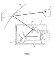
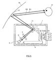
- Fig. 4 and 5 are diagrams showing other embodiments of the invention.
- the combiner member reflecting the display light L and the infrared rays R1 and R2 is configured of a windshield W on which a multilayer film 10 is formed. It is also possible to obtain the advantages of the invention with such a configuration.
- Reference numeral 11 showing a concave mirror which reflects the display light L and the infrared ray R1 toward the windshield W, and reflects the infrared ray R2, caused to fall incident from the exterior, toward the first and second imaging means 6 and 7,
- the concave mirror 11 is provided so as to be angle adjustable by angle adjustment means 11a (adjustment means) configured of an not-shown motor, gear, and the like in such a way that the driver D easily and visually perceives the display light L. It is possible to adjust the virtual image V formation position by rotating the concave mirror 11 by means of the angle adjustment means 11a.
- the multilayer film 10 is formed as appropriate in order to make an adjustment in such a way that the reflection of the display light L and infrared ray R1 is efficiently carried out.
- the invention relating to a structure for accurately calculating an eye position of the user, a result of the calculation of the user's eye position is applicable not only to the display image position adjustment of each of the embodiments, but to a detection of a line or point of sight of the user, and a determination of a condition of the user such as inattentiveness or drowsiness.
Abstract
Description
- The present invention relates to a head-up display apparatus configured so that visible light emitted from display means is reflected toward a user by a combiner member, forming a display image, and particularly, to form a structure for accurately calculating an eye position of the user.
- Usually, as this kind of head-up display apparatus, one described in
Patent Document 1 below has been known. With such a head-up display apparatus, it is also possible to use a combiner, and a reflecting member, of the head-up display apparatus in imaging a user by disposing an imaging device which captures an image of the user in the optical axis of the head-up display apparatus, thereby to reduce the number of dedicated members required for the imaging, captures an image of the user (particularly the user's face) with a simpler configuration, and calculate an eye position of the user. A result of the determination of the user' s eye position is applicable not only to a display image position adjustment disclosed inPatent Document 1, but to a detection of a line or point of sight of the user and a determination of a condition of the user such as looking aside or falling asleep while driving.
Patent Document 1:JP-A-8-156646 - However, with the previously described head-up display apparatus in
Patent Document 1, a single imaging device is simply provided in an optical unit, so that there has been a problem in that a position detection accuracy, particularly in a front-rear direction of a vehicle, is low, and it is difficult to accurately calculate the user's eye position. - The invention, focusing on the previously described problem, has an object of providing a head-up display apparatus having a structure capable of capturing an image of a user and which can accurately calculate the user's eye position.
- In order to solve the previously described problem, the invention, being a head-up display apparatus configured so that visible light emitted from display means is reflected toward a user by a combiner member, forming a display image, is characterized by including infrared ray emitting means, which emits an infrared ray toward the user, a mirror member, which reflects the visible light, emitted from the display means, toward the combiner member, and transmits the infrared ray reflected by the user and the combiner member, a plurality of imaging means, which sense the infrared ray transmitted through the mirror member, and each image the user from different directions, and image processing means, which calculates the user's eye position based on an image captured by the imaging means.
- Also, the invention is characterized in that the infrared ray emitting means is disposed in such a way as to face the mirror member, and is positioned between the plurality of imaging means.
- Also, the invention is characterized in that a light shielding member is disposed between the infrared ray emitting means and the plurality of imaging means.
- Also, the invention is characterized in that the light shielding member is disposed in such a way as to come into contact with the mirror member.
- Also, the invention is characterized in that the mirror member is configured of a cold mirror.
- Also, the invention is characterized in that the combiner member is configured of a windshield of a vehicle.
- Also, the invention is characterized in that the combiner member is configured of a concave mirror disposed on a dashboard of the vehicle.
- Also, the invention, including adjustment means which can adjust a position of formation of the display image, is characterized in that the adjustment means, based on a result of the calculation by the image processing means, adjusts the display image formation position. Advantage of the Invention
- The invention relates to a head-up display apparatus in which visible light emitted from display means is reflected toward a user by a combiner member to form a display image, and has a structure capable of capturing an image of the user, enabling the user's eye position to be accurately calculated.
-
- [
Fig. 1 ] A schematic diagram of a head-up display apparatus which is an embodiment of the invention. - [
Fig. 2 ] A schematic diagram of the head-up display apparatus. - [
Fig. 3 ] A diagram showing infrared ray emitting means, and first and second imaging means, of the head-up display apparatus. - [
Fig. 4 ] A schematic diagram of a head-up display apparatus which is another embodiment of the invention. - [
Fig. 5 ] A schematic diagram of the head-up display apparatus. -
- 1
- Housing
- 2
- Display means
- 3
- Cold mirror (mirror member)
- 4
- Concave mirror (combiner member)
- 5
- Infrared ray emitting means
- 6
- First imaging means
- 7
- Second imaging means
- 8
- Image processing means
- 9
- Light shielding member
- D
- Driver (user)
- L
- Display light (visible light)
- R1
- Infrared ray
- R2
- Infrared ray
- V
- Virtual image (display image)
- W
- Windshield
- Hereafter, a description will be given, based on the accompanying drawings, of embodiments of the invention.
- Hereafter, a description will be given, based on the accompanying drawings, of a head-up display apparatus which is an embodiment of the invention.
- As shown in
Figs. 1 and2 , the head-up display apparatus is configured mainly of ahousing 1, display means 2, a cold mirror (a mirror member) 3, a concave mirror (a combiner member) 4, infrared ray emitting means 5, first imaging means 6, second imaging means 7, and image processing means 8. - With such a head-up display apparatus, as shown in
Fig. 1 , by display light (visible light) L emitted from the display means 2 being reflected by theconcave mirror 4, and directed to a driver (a user) D, a virtual image (a display image) V is formed in such a way as to be positioned at a front of a vehicle (on a windshield W side). Also, with such a head-up display apparatus, as shown inFig. 2 , an infrared ray R1 emitted from the infraredray emitting means 5 is transmitted through thecold mirror 3, is also reflected by theconcave mirror 4, and directed to the driver D, and furthermore, an infrared ray R2 reflected off the driver D is reflected toward thecold mirror 3 by theconcave mirror 4, is transmitted through thecold mirror 3, and applied to the first and second imaging means 6 and 7, thereby imaging the driver D (particularly his or her face). Consequently, it is possible to carry out an imaging of the driver D utilizing the optical path of the head-up display apparatus, and to image the driver D with a simpler configuration. - The
housing 1, being made of an opaque synthetic resin material, is provided with anopening 1a through an upper portion thereof (on the windshield W side) in a position in which theconcave mirror 4 is disposed. - The display means 2, being disposed in the
housing 1, has visible light LED' s 2a, alens array 2b, awiring substrate 2c, aheat radiating member 2d, and a liquidcrystal display element 2e. - The visible light LED's 2a such as chip LED's are mounted on a surface of the
wiring substrate 2c on thelens array 2b side. Also, the visible light LED's 2a with a low directivity (in the embodiment, 20 to 30 degrees), are respectively provided in each of positions corresponding to spherical surfaces of thelens array 2b. In this case, for thevisible light LEDs 2a, two of which glow white are used. - The
lens array 2b, being made of a transmissive synthetic resin material (for example, an acrylic resin), is provided in thehousing 1. Thelens array 2b, being configured forming a plurality of similar convex spherical surfaces (convexities) corresponding to the individual visible light LED's 2a, causes illumination lights from the visible light LED's 2a to be refracted by the spherical surfaces, enabling a visible light L with evenness to be applied to the liquidcrystal display element 2e which is an illuminated member. - The
wiring substrate 2c, preferably, an aluminum substrate with a high thermal conductivity, is provided on a rear side of the liquidcrystal display element 2e inside thehousing 1 in such a way as to be parallel with a predetermined distance to thelens array 2b. Thewiring substrate 2c, on which are mounted electronic parts such as at least the visible light LED's 2a, is provided with wiring for supplying power to the electronic parts. The predetermined distance varies depending on the directivity of the visible light LED's 2a and the shape of the spherical surfaces of thelens array 2b, and such a distance as causes less unevenness in luminance is selected. - The
heat radiating member 2d, preferably, a metal material with a high thermal conductivity, is disposed in such a way as to come into contact with thewiring substrate 2c, and have one portion thereof exposed outside thehousing 1. Theheat radiating member 2d has a function of radiating heat generated by a drive of the visible light LED's 2a to the exterior. - The liquid
crystal display element 2e is configured so that a color filter having a red layer, a green layer, and a blue layer which are provided depending on a number of display pixels is disposed on the front surface of a liquid crystal cell having liquid crystal sealed between a pair of transmissive substrates. Also, polarizing films (polarizing members) are attached to the front and rear surfaces of the liquidcrystal display element 2e. The liquidcrystal display element 2e, being provided in thehousing 1, is provided in a position in which illumination lights from the visible light LED's 2a provided behind the liquidcrystal display element 2e reach via thelens array 2b. The illumination lights transmitted through the liquidcrystal display element 2e are emitted to thecold mirror 3 as the display light L. With the liquidcrystal display element 2e, it is possible to indicate vehicle speed and engine speed measurements as numeric values by means of, for example, a calculation circuit (not shown), which measures a vehicle speed and engine speed based on output signals from a vehicle speed sensor and engine rotation sensor provided in the vehicle, and a liquid crystal drive circuit (not shown), which drives liquid crystal based on results of the calculation. For the liquidcrystal display element 2e, in the embodiment, a TFT type is applied, and a full color display is possible. - The
cold mirror 3, being configured of a glass substrate and a reflecting film formed on a surface of the glass substrate by vapor deposition, is provided tilted at a predetermined angle to the optical axes of the visible light LED's 2a. The reflecting film of thecold mirror 3 has a property of transmitting only an infrared ray, and reflecting a visible light ray and an ultraviolet ray. That is, the display light L transmitted through the liquidcrystal display element 2e is reflected toward theconcave mirror 4 by thecold mirror 3. Also, by using thecold mirror 3, the infrared ray R2 caused to fall incident inside thehousing 1 from the exterior is transmitted through thecold mirror 3, and directed to the first and second imaging means 6 and 7 (refer toFig. 2 ). - The
concave mirror 4, provided corresponding to theopening 1a in thehousing 1, which reflects the display light L, projected via the liquidcrystal display element 2e andcold mirror 3, to the driver D side, is provided so as to be angle adjustable by angle adjustment means 4a (adjustment means) configured of an not-shown motor, gear, and the like in such a way that the driver D easily visually perceives the display light L. A position in which the virtual image V is formed can be adjusted by rotating theconcave mirror 4 by means of the angle adjustment means 4a. Also, theconcave mirror 4 is formed of a reflecting surface having a predetermined curvature in order that the display light L is displayed enlarged. Also, theconcave mirror 4 reflects the infrared ray R1, emitted from the infrared ray emitting means 5, toward the driver D, and furthermore, reflects the infrared ray R2, reflected by the user D, toward the first and second imaging means 6 and 7 (refer toFig. 2 ). - The infrared ray emitting means 5, emitting the infrared ray R1 toward the
concave mirror 4, is disposed in thehousing 1 in such a way as to face theconcave mirror 4 across thecold mirror 3. As shown inFig. 3 , the infrared ray emitting means 5 has aninfrared LED 5a emitting an infrared ray, acollective lens 5b made of a convex resin material, acircuit substrate 5c, and aheat radiating member 5d. The infrared ray emitted from theinfrared LED 5a, the distribution of which is controlled by thecollective lens 5b, is transmitted through thecold mirror 3, and emitted toward theconcave mirror 4. Thecircuit substrate 5c andheat radiating member 2d are made of a metal material with a high thermal conductivity in order to radiate heat generated by a drive of theinfrared LED 5a to the exterior. - The first and second imaging means 6 and 7, each of which is configured of a CCD camera or the like which senses an infrared ray, and captures an image (in the embodiment, a facial image of the driver D), are disposed in the
housing 1 in such a way as to face theconcave mirror 4 across thecold mirror 3, as well as to surround the infrared ray emitting means 5. By the infrared ray emitting means 5 being disposed in such a way as to be positioned between the first and second imaging means 6 and 7, it is possible to increase a distance between the first and second imaging means 6 and 7, and it is possible to improve the accuracy with which is detected an eye position of the driver D, to be described hereafter. - Also, as shown in
Fig. 3 , alight shielding member 9 is disposed between the infrared ray emitting means 5 and the first and second imaging means 6 and 7. Thelight shielding member 9, being made of, for example, a cylindrical metal material, shields the infrared ray R1 so that the infrared ray R1 emitted from the infrared LED is not directly sensed by the first and second imaging means 6 and 7. For this reason, thelight shielding member 9, being disposed in such a way as to come into contact with thecold mirror 3, has a configuration such that no clearance is formed between itself and thecold mirror 3. By providing thelight shielding member 9, it is possible to prevent theinfrared LED 5a from being directly imaged by the first and second imaging means 6 and 7, and by housing the infrared ray emitting means 5 in thehousing 1, a simple configuration is possible wherein no special attachment is necessary, and it is possible to efficiently carry out capturing a image of the driver D. - The image processing means 8, being disposed in the
housing 1, is electrically connected to the first and second imaging means 6 and 7. The image processing means 8 receives facial images of the driver D captured in different directions from the first and second imaging means 6 and 7, and calculates an eye position of the driver D from such a plurality of facial images. By calculating the eye position of the driver D based on the facial images from the plurality of differing angles in such a way, it is also possible to accurately calculate the eye position in a front-rear direction of the vehicle. A result of the calculation of the eye position of the driver D is transmitted to not-shown control means. The control means has a function of driving the angle adjustment means 4a, for example, based on such a calculation result, making an automatic adjustment in such a way that the virtual image V is positioned so as to be well visible to the driver D. The function utilizing the eye position calculation result is not limited to the heretofore described virtual image V formation position adjustment. -
Fig. 4 and5 are diagrams showing other embodiments of the invention. A difference from the heretofore described embodiment is that the combiner member reflecting the display light L and the infrared rays R1 and R2 is configured of a windshield W on which amultilayer film 10 is formed. It is also possible to obtain the advantages of the invention with such a configuration.Reference numeral 11 showing a concave mirror which reflects the display light L and the infrared ray R1 toward the windshield W, and reflects the infrared ray R2, caused to fall incident from the exterior, toward the first and second imaging means 6 and 7, theconcave mirror 11 is provided so as to be angle adjustable by angle adjustment means 11a (adjustment means) configured of an not-shown motor, gear, and the like in such a way that the driver D easily and visually perceives the display light L. It is possible to adjust the virtual image V formation position by rotating theconcave mirror 11 by means of the angle adjustment means 11a. Also, themultilayer film 10 is formed as appropriate in order to make an adjustment in such a way that the reflection of the display light L and infrared ray R1 is efficiently carried out. Industrial Applicability - The invention relating to a structure for accurately calculating an eye position of the user, a result of the calculation of the user's eye position is applicable not only to the display image position adjustment of each of the embodiments, but to a detection of a line or point of sight of the user, and a determination of a condition of the user such as inattentiveness or drowsiness.
Claims (8)
- A head-up display apparatus configured to reflect visible light emitted from display means toward a user by a combiner member to form a display image, the head-up display apparatus comprising:infrared ray emitting means for emitting an infrared ray toward the user;a mirror member for reflecting the visible light emitted from the display means toward the combiner member, and transmitting the infrared ray reflected by the user and the combiner member;a plurality of imaging means for sensing the infrared ray transmitted through the mirror member, and each imaging the user from differing directions; andimage processing means for calculating the user's eye position based on an image captured by the imaging means.
- The head-up display apparatus according to claim 1,
wherein the infrared ray emitting means is disposed to face the mirror member and be positioned between the plurality of imaging means. - The head-up display apparatus according to claim 1 or 2,
wherein a light shielding member is disposed between the infrared ray emitting means and the plurality of imaging means. - The head-up display apparatus according to claim 3,
wherein the light shielding member is disposed to come in contact with the mirror member. - The head-up display apparatus according to claim 1,
wherein the mirror member comprises a cold mirror. - The head-up display apparatus according to claim 1,
wherein the combiner member comprises a windshield for a vehicle. - The head-up display apparatus according to claim 1,
wherein the combiner member comprises a concave mirror disposed on a dashboard of the vehicle. - The head-up display apparatus according to claim 1, further comprising:adjustment means for adjusting a position of formation of the display image, the adjustment means adjusting the display image formation position based on a result of the calculation by the image processing means.
Applications Claiming Priority (2)
| Application Number | Priority Date | Filing Date | Title |
|---|---|---|---|
| JP2006317888A JP4895324B2 (en) | 2006-11-27 | 2006-11-27 | Head-up display device |
| PCT/JP2007/069802 WO2008068956A1 (en) | 2006-11-27 | 2007-10-11 | Head-up display device |
Publications (3)
| Publication Number | Publication Date |
|---|---|
| EP2093094A1 true EP2093094A1 (en) | 2009-08-26 |
| EP2093094A4 EP2093094A4 (en) | 2010-06-02 |
| EP2093094B1 EP2093094B1 (en) | 2013-06-26 |
Family
ID=39491867
Family Applications (1)
| Application Number | Title | Priority Date | Filing Date |
|---|---|---|---|
| EP07829540.9A Active EP2093094B1 (en) | 2006-11-27 | 2007-10-11 | Head-up display device |
Country Status (4)
| Country | Link |
|---|---|
| US (1) | US7936518B2 (en) |
| EP (1) | EP2093094B1 (en) |
| JP (1) | JP4895324B2 (en) |
| WO (1) | WO2008068956A1 (en) |
Cited By (6)
| Publication number | Priority date | Publication date | Assignee | Title |
|---|---|---|---|---|
| WO2012007305A1 (en) * | 2010-07-16 | 2012-01-19 | Delphi Technologies, Inc. | Adjustable head-up display device |
| WO2013079479A1 (en) | 2011-11-28 | 2013-06-06 | Delphi Technologies, Inc. | Head-up display device comprising a retractable combiner |
| GB2498715A (en) * | 2012-01-20 | 2013-07-31 | Bae Systems Plc | Head up display providing two non-coincident virtual images |
| WO2014207329A1 (en) * | 2013-06-28 | 2014-12-31 | Valeo Comfort And Driving Assistance | Display, in particular heads-up display, particularly for a motor vehicle |
| EP2843652A4 (en) * | 2012-04-24 | 2016-01-13 | Nippon Seiki Co Ltd | Heads-up display device |
| CN109799610A (en) * | 2017-11-16 | 2019-05-24 | Aptiv技术有限公司 | Eye tracking apparatus |
Families Citing this family (57)
| Publication number | Priority date | Publication date | Assignee | Title |
|---|---|---|---|---|
| US8297550B2 (en) * | 2007-08-09 | 2012-10-30 | Lta Corporation | Lenticular airship and associated controls |
| US8894002B2 (en) | 2010-07-20 | 2014-11-25 | Lta Corporation | System and method for solar-powered airship |
| JP4686586B2 (en) * | 2008-09-19 | 2011-05-25 | 株式会社東芝 | In-vehicle display device and display method |
| JP5259429B2 (en) * | 2009-01-05 | 2013-08-07 | 株式会社東芝 | Display device |
| JP5222165B2 (en) * | 2009-01-27 | 2013-06-26 | 株式会社沖データ | Light source device and head-up display device having the same |
| JP5240222B2 (en) * | 2010-03-26 | 2013-07-17 | 株式会社デンソー | Head-up display device |
| CN102269873A (en) * | 2010-06-04 | 2011-12-07 | 富港电子(东莞)有限公司 | Head-up display system |
| DE102010040694A1 (en) * | 2010-09-14 | 2012-03-15 | Robert Bosch Gmbh | Head-Up Display |
| US10036891B2 (en) * | 2010-10-12 | 2018-07-31 | DISH Technologies L.L.C. | Variable transparency heads up displays |
| JP5392276B2 (en) * | 2011-02-03 | 2014-01-22 | 株式会社デンソー | Virtual image display device |
| BR112013024635A2 (en) | 2011-03-31 | 2020-09-01 | Lta Corporation | aircraft including aerodynamic, flotation and implantable structures |
| US8767306B1 (en) * | 2011-09-22 | 2014-07-01 | Google Inc. | Display system |
| JP5919724B2 (en) * | 2011-10-20 | 2016-05-18 | 日本精機株式会社 | Head-up display device for vehicle |
| JP5990399B2 (en) * | 2012-05-09 | 2016-09-14 | 矢崎総業株式会社 | Vehicle display device |
| WO2014162418A1 (en) * | 2013-04-01 | 2014-10-09 | パイオニア株式会社 | Virtual image display apparatus |
| US9658453B1 (en) * | 2013-04-29 | 2017-05-23 | Google Inc. | Head-mounted display including diffractive combiner to integrate a display and a sensor |
| US9758256B1 (en) * | 2013-08-06 | 2017-09-12 | The Boeing Company | Pilot-configurable information on a display unit |
| EA201690928A1 (en) | 2013-11-04 | 2016-10-31 | ЭлТиЭй КОРПОРЕЙШН | CARGO DIRIJABL |
| KR20150100452A (en) * | 2014-02-25 | 2015-09-02 | 최해용 | High brightness head-up display device |
| JP6408774B2 (en) * | 2014-03-25 | 2018-10-17 | 矢崎総業株式会社 | Head-up display device |
| EP3133435A4 (en) * | 2014-04-14 | 2017-03-29 | Panasonic Intellectual Property Management Co., Ltd. | Headup display and mobile body having headup display mounted therein |
| JP6540988B2 (en) * | 2014-06-09 | 2019-07-10 | 日本精機株式会社 | Head-up display device |
| WO2015190240A1 (en) * | 2014-06-12 | 2015-12-17 | 矢崎総業株式会社 | Bezel member and vehicular display device |
| WO2015190238A1 (en) * | 2014-06-12 | 2015-12-17 | 矢崎総業株式会社 | Display device for vehicle |
| TW201606350A (en) | 2014-08-12 | 2016-02-16 | Automotive Res & Testing Ct | Head-up display device |
| US11347067B2 (en) * | 2014-12-12 | 2022-05-31 | Young Optics Inc. | Display system |
| WO2016113873A1 (en) * | 2015-01-15 | 2016-07-21 | パイオニア株式会社 | Display device, control method, program, and storage medium |
| JP6558017B2 (en) * | 2015-03-27 | 2019-08-14 | 日本精機株式会社 | Head-up display |
| DE102015004744A1 (en) | 2015-04-11 | 2016-10-13 | Audi Ag | Modular head-up display for a motor vehicle |
| JP6458998B2 (en) * | 2015-05-13 | 2019-01-30 | 日本精機株式会社 | Head-up display |
| US10416449B2 (en) * | 2015-06-24 | 2019-09-17 | Pioneer Corporation | Display apparatus having moving mechanism |
| TWM514078U (en) * | 2015-07-08 | 2015-12-11 | Xin Rui Fong Int Co Ltd | Advanced type vehicle lift-up information display |
| JP6367166B2 (en) | 2015-09-01 | 2018-08-01 | 株式会社東芝 | Electronic apparatus and method |
| DE102016205309A1 (en) * | 2016-03-31 | 2017-10-05 | Robert Bosch Gmbh | Illumination device for illuminating a driver of a vehicle with infrared light, driver observation system and head-up display unit |
| TWI583997B (en) * | 2016-04-01 | 2017-05-21 | 揚昇照明股份有限公司 | Display box |
| US10274725B2 (en) * | 2016-06-20 | 2019-04-30 | Denso International America, Inc. | Head-up display with second high intensity lighting unit installed outside of first display casing |
| DE102016214438B4 (en) * | 2016-08-04 | 2022-07-07 | Volkswagen Aktiengesellschaft | Motor vehicle with a head-up display and method of operating the same |
| CN106226911A (en) * | 2016-09-09 | 2016-12-14 | 深圳市世尊科技有限公司 | A kind of intelligent glasses and exchange method being carried out man-machine interaction by sight line |
| JP6731821B2 (en) * | 2016-09-28 | 2020-07-29 | 京セラ株式会社 | Display device and display system |
| JP6825903B2 (en) * | 2016-12-27 | 2021-02-03 | 矢崎総業株式会社 | Driver imager |
| TWI631027B (en) * | 2016-12-27 | 2018-08-01 | 怡利電子工業股份有限公司 | Head-up display device for long-distance imaging |
| US10203498B2 (en) * | 2017-01-07 | 2019-02-12 | E-Lead Electronic Co., Ltd. | Long distance imaging head-up display device |
| DE202017100257U1 (en) | 2017-01-18 | 2017-01-26 | E-Lead Electronic Co., Ltd. | Head-up display with multi-display function |
| DE202017100254U1 (en) | 2017-01-18 | 2017-01-26 | E-Lead Electronic Co., Ltd. | Head-up display for imaging at long range |
| JP6811106B2 (en) * | 2017-01-25 | 2021-01-13 | 矢崎総業株式会社 | Head-up display device and display control method |
| JP6817088B2 (en) * | 2017-01-26 | 2021-01-20 | 矢崎総業株式会社 | Display device and display device body |
| US11241960B2 (en) * | 2017-04-19 | 2022-02-08 | Maxell, Ltd. | Head up display apparatus and display control method thereof |
| US20190012552A1 (en) * | 2017-07-06 | 2019-01-10 | Yves Lambert | Hidden driver monitoring |
| US11135917B2 (en) | 2018-09-05 | 2021-10-05 | Denso International America, Inc. | Forward collision avoidance display |
| DE202018106156U1 (en) | 2018-10-26 | 2018-11-08 | E-Lead Electronic Co., Ltd. | Embedded head-up display device |
| GB2583483B (en) * | 2019-04-29 | 2021-05-19 | Envisics Ltd | Image capture and display system |
| US10860093B1 (en) * | 2019-08-28 | 2020-12-08 | GM Global Technology Operations LLC | Eye location tracking device integrated with head-up display |
| JP7207251B2 (en) * | 2019-10-09 | 2023-01-18 | 株式会社デンソー | vehicle display |
| WO2021172333A1 (en) * | 2020-02-28 | 2021-09-02 | 日本精機株式会社 | Vehicle display device |
| CN113539060A (en) * | 2020-04-20 | 2021-10-22 | 华为技术有限公司 | Desktop display device and electronic equipment |
| JP7342835B2 (en) | 2020-10-21 | 2023-09-12 | 株式会社デンソー | monitoring device |
| CN115903236A (en) * | 2022-10-19 | 2023-04-04 | 江苏泽景汽车电子股份有限公司 | Head-up display |
Citations (4)
| Publication number | Priority date | Publication date | Assignee | Title |
|---|---|---|---|---|
| US4962998A (en) * | 1987-09-07 | 1990-10-16 | Yazaki Corporation | Indication display unit for vehicles |
| JPH092102A (en) * | 1995-06-16 | 1997-01-07 | Sumitomo Electric Ind Ltd | Head-up display mounted on vehicle |
| US5659327A (en) * | 1992-10-22 | 1997-08-19 | Board Of Regents Of The University Of Washington | Virtual retinal display |
| US5734357A (en) * | 1994-12-02 | 1998-03-31 | Fujitsu Limited | Vehicular display device adjusting to driver's positions |
Family Cites Families (7)
| Publication number | Priority date | Publication date | Assignee | Title |
|---|---|---|---|---|
| JPS60183238A (en) * | 1984-02-28 | 1985-09-18 | Nippon Denso Co Ltd | Running information display device for vehicle |
| JPH06247184A (en) * | 1993-03-01 | 1994-09-06 | Aisin Seiki Co Ltd | Display device on vehicle |
| JP4007633B2 (en) * | 1996-10-09 | 2007-11-14 | 株式会社島津製作所 | Head up display |
| US7111939B2 (en) * | 2001-01-22 | 2006-09-26 | Eastman Kodak Company | Image display system with body position compensation |
| JP3766326B2 (en) * | 2001-12-10 | 2006-04-12 | 日本電信電話株式会社 | Light irradiation receiver |
| JP2003344801A (en) * | 2002-05-28 | 2003-12-03 | Nippon Seiki Co Ltd | Display device |
| JP2006224919A (en) * | 2005-02-21 | 2006-08-31 | Yazaki Corp | Virtual image display device for vehicle |
-
2006
- 2006-11-27 JP JP2006317888A patent/JP4895324B2/en active Active
-
2007
- 2007-10-11 WO PCT/JP2007/069802 patent/WO2008068956A1/en active Application Filing
- 2007-10-11 EP EP07829540.9A patent/EP2093094B1/en active Active
- 2007-10-11 US US12/516,463 patent/US7936518B2/en not_active Expired - Fee Related
Patent Citations (4)
| Publication number | Priority date | Publication date | Assignee | Title |
|---|---|---|---|---|
| US4962998A (en) * | 1987-09-07 | 1990-10-16 | Yazaki Corporation | Indication display unit for vehicles |
| US5659327A (en) * | 1992-10-22 | 1997-08-19 | Board Of Regents Of The University Of Washington | Virtual retinal display |
| US5734357A (en) * | 1994-12-02 | 1998-03-31 | Fujitsu Limited | Vehicular display device adjusting to driver's positions |
| JPH092102A (en) * | 1995-06-16 | 1997-01-07 | Sumitomo Electric Ind Ltd | Head-up display mounted on vehicle |
Non-Patent Citations (1)
| Title |
|---|
| See also references of WO2008068956A1 * |
Cited By (13)
| Publication number | Priority date | Publication date | Assignee | Title |
|---|---|---|---|---|
| US9063327B2 (en) | 2010-07-16 | 2015-06-23 | Delphi Technologies, Inc. | Adjustable head-up display device |
| FR2962815A1 (en) * | 2010-07-16 | 2012-01-20 | Delphi Tech Inc | HEIGHT ADJUSTABLE HEAD DISPLAY DEVICE |
| CN103069326A (en) * | 2010-07-16 | 2013-04-24 | 德尔菲技术公司 | Adjustable head-up display device |
| WO2012007305A1 (en) * | 2010-07-16 | 2012-01-19 | Delphi Technologies, Inc. | Adjustable head-up display device |
| CN103069326B (en) * | 2010-07-16 | 2015-07-01 | 德尔菲技术公司 | Adjustable head-up display device |
| EP2682803A3 (en) * | 2010-07-16 | 2014-02-26 | Delphi Technologies, Inc. | Adjustable head up display |
| WO2013079479A1 (en) | 2011-11-28 | 2013-06-06 | Delphi Technologies, Inc. | Head-up display device comprising a retractable combiner |
| GB2498715A (en) * | 2012-01-20 | 2013-07-31 | Bae Systems Plc | Head up display providing two non-coincident virtual images |
| EP2843652A4 (en) * | 2012-04-24 | 2016-01-13 | Nippon Seiki Co Ltd | Heads-up display device |
| FR3007852A1 (en) * | 2013-06-28 | 2015-01-02 | Valeo Etudes Electroniques | DISPLAY, INCLUDING HIGH HEAD DISPLAY, ESPECIALLY FOR MOTOR VEHICLE |
| WO2014207329A1 (en) * | 2013-06-28 | 2014-12-31 | Valeo Comfort And Driving Assistance | Display, in particular heads-up display, particularly for a motor vehicle |
| US10203500B2 (en) | 2013-06-28 | 2019-02-12 | Valeo Comfort And Driving Assistance | Display, in particular heads-up display, particularly for a motor vehicle |
| CN109799610A (en) * | 2017-11-16 | 2019-05-24 | Aptiv技术有限公司 | Eye tracking apparatus |
Also Published As
| Publication number | Publication date |
|---|---|
| JP2008126984A (en) | 2008-06-05 |
| US20100067118A1 (en) | 2010-03-18 |
| US7936518B2 (en) | 2011-05-03 |
| JP4895324B2 (en) | 2012-03-14 |
| EP2093094B1 (en) | 2013-06-26 |
| WO2008068956A1 (en) | 2008-06-12 |
| EP2093094A4 (en) | 2010-06-02 |
Similar Documents
| Publication | Publication Date | Title |
|---|---|---|
| EP2093094B1 (en) | Head-up display device | |
| JP5145710B2 (en) | Head-up display device | |
| JP4973921B2 (en) | Head-up display device | |
| JP2008155720A (en) | Head up display device | |
| JP5955153B2 (en) | Display device | |
| JP3727078B2 (en) | Display device | |
| JP6004706B2 (en) | Display device and head-up display system provided with the same | |
| KR101131983B1 (en) | A head-up display device for vehicle moving the projecting position of virtual images by the vehicle velocity | |
| CN204009232U (en) | Optical imaging device | |
| US11235706B2 (en) | Display system | |
| WO2015012280A1 (en) | Sight line detection device | |
| US11394952B2 (en) | Imaging device and vehicular display device | |
| WO2018171211A1 (en) | Vehicle-mounted system and vehicle | |
| KR20190017983A (en) | A display device for superimposing a virtual image on a user's field of view | |
| US10401621B2 (en) | Display unit for vehicle head-up display system | |
| JP2015024798A (en) | Auxiliary image display device of blind area | |
| JP2008268680A (en) | Display device | |
| JP2020027116A (en) | Information display device and information display method | |
| JP2007294317A (en) | Light source device, and image display device | |
| JP2007114743A (en) | Display apparatus | |
| JP7230750B2 (en) | Display device | |
| CN110891827B (en) | Imaging device and display device for vehicle | |
| WO2020070970A1 (en) | Vehicular display device | |
| WO2019138970A1 (en) | Projection distance measurement method and device | |
| JP2008261901A (en) | Liquid crystal display |
Legal Events
| Date | Code | Title | Description |
|---|---|---|---|
| PUAI | Public reference made under article 153(3) epc to a published international application that has entered the european phase |
Free format text: ORIGINAL CODE: 0009012 |
|
| 17P | Request for examination filed |
Effective date: 20090625 |
|
| AK | Designated contracting states |
Kind code of ref document: A1 Designated state(s): AT BE BG CH CY CZ DE DK EE ES FI FR GB GR HU IE IS IT LI LT LU LV MC MT NL PL PT RO SE SI SK TR |
|
| DAX | Request for extension of the european patent (deleted) | ||
| A4 | Supplementary search report drawn up and despatched |
Effective date: 20100503 |
|
| GRAP | Despatch of communication of intention to grant a patent |
Free format text: ORIGINAL CODE: EPIDOSNIGR1 |
|
| GRAS | Grant fee paid |
Free format text: ORIGINAL CODE: EPIDOSNIGR3 |
|
| GRAA | (expected) grant |
Free format text: ORIGINAL CODE: 0009210 |
|
| AK | Designated contracting states |
Kind code of ref document: B1 Designated state(s): AT BE BG CH CY CZ DE DK EE ES FI FR GB GR HU IE IS IT LI LT LU LV MC MT NL PL PT RO SE SI SK TR |
|
| REG | Reference to a national code |
Ref country code: GB Ref legal event code: FG4D |
|
| REG | Reference to a national code |
Ref country code: CH Ref legal event code: EP |
|
| REG | Reference to a national code |
Ref country code: AT Ref legal event code: REF Ref document number: 618539 Country of ref document: AT Kind code of ref document: T Effective date: 20130715 |
|
| REG | Reference to a national code |
Ref country code: IE Ref legal event code: FG4D |
|
| REG | Reference to a national code |
Ref country code: DE Ref legal event code: R096 Ref document number: 602007031302 Country of ref document: DE Effective date: 20130822 |
|
| PG25 | Lapsed in a contracting state [announced via postgrant information from national office to epo] |
Ref country code: LT Free format text: LAPSE BECAUSE OF FAILURE TO SUBMIT A TRANSLATION OF THE DESCRIPTION OR TO PAY THE FEE WITHIN THE PRESCRIBED TIME-LIMIT Effective date: 20130626 Ref country code: SI Free format text: LAPSE BECAUSE OF FAILURE TO SUBMIT A TRANSLATION OF THE DESCRIPTION OR TO PAY THE FEE WITHIN THE PRESCRIBED TIME-LIMIT Effective date: 20130626 Ref country code: FI Free format text: LAPSE BECAUSE OF FAILURE TO SUBMIT A TRANSLATION OF THE DESCRIPTION OR TO PAY THE FEE WITHIN THE PRESCRIBED TIME-LIMIT Effective date: 20130626 Ref country code: SE Free format text: LAPSE BECAUSE OF FAILURE TO SUBMIT A TRANSLATION OF THE DESCRIPTION OR TO PAY THE FEE WITHIN THE PRESCRIBED TIME-LIMIT Effective date: 20130626 Ref country code: GR Free format text: LAPSE BECAUSE OF FAILURE TO SUBMIT A TRANSLATION OF THE DESCRIPTION OR TO PAY THE FEE WITHIN THE PRESCRIBED TIME-LIMIT Effective date: 20130927 |
|
| REG | Reference to a national code |
Ref country code: AT Ref legal event code: MK05 Ref document number: 618539 Country of ref document: AT Kind code of ref document: T Effective date: 20130626 |
|
| REG | Reference to a national code |
Ref country code: LT Ref legal event code: MG4D |
|
| PG25 | Lapsed in a contracting state [announced via postgrant information from national office to epo] |
Ref country code: BG Free format text: LAPSE BECAUSE OF FAILURE TO SUBMIT A TRANSLATION OF THE DESCRIPTION OR TO PAY THE FEE WITHIN THE PRESCRIBED TIME-LIMIT Effective date: 20130926 |
|
| REG | Reference to a national code |
Ref country code: NL Ref legal event code: VDEP Effective date: 20130626 |
|
| PG25 | Lapsed in a contracting state [announced via postgrant information from national office to epo] |
Ref country code: LV Free format text: LAPSE BECAUSE OF FAILURE TO SUBMIT A TRANSLATION OF THE DESCRIPTION OR TO PAY THE FEE WITHIN THE PRESCRIBED TIME-LIMIT Effective date: 20130626 |
|
| PG25 | Lapsed in a contracting state [announced via postgrant information from national office to epo] |
Ref country code: PT Free format text: LAPSE BECAUSE OF FAILURE TO SUBMIT A TRANSLATION OF THE DESCRIPTION OR TO PAY THE FEE WITHIN THE PRESCRIBED TIME-LIMIT Effective date: 20131028 Ref country code: CZ Free format text: LAPSE BECAUSE OF FAILURE TO SUBMIT A TRANSLATION OF THE DESCRIPTION OR TO PAY THE FEE WITHIN THE PRESCRIBED TIME-LIMIT Effective date: 20130626 Ref country code: EE Free format text: LAPSE BECAUSE OF FAILURE TO SUBMIT A TRANSLATION OF THE DESCRIPTION OR TO PAY THE FEE WITHIN THE PRESCRIBED TIME-LIMIT Effective date: 20130626 Ref country code: BE Free format text: LAPSE BECAUSE OF FAILURE TO SUBMIT A TRANSLATION OF THE DESCRIPTION OR TO PAY THE FEE WITHIN THE PRESCRIBED TIME-LIMIT Effective date: 20130626 Ref country code: SK Free format text: LAPSE BECAUSE OF FAILURE TO SUBMIT A TRANSLATION OF THE DESCRIPTION OR TO PAY THE FEE WITHIN THE PRESCRIBED TIME-LIMIT Effective date: 20130626 Ref country code: AT Free format text: LAPSE BECAUSE OF FAILURE TO SUBMIT A TRANSLATION OF THE DESCRIPTION OR TO PAY THE FEE WITHIN THE PRESCRIBED TIME-LIMIT Effective date: 20130626 Ref country code: IS Free format text: LAPSE BECAUSE OF FAILURE TO SUBMIT A TRANSLATION OF THE DESCRIPTION OR TO PAY THE FEE WITHIN THE PRESCRIBED TIME-LIMIT Effective date: 20131026 Ref country code: CY Free format text: LAPSE BECAUSE OF FAILURE TO SUBMIT A TRANSLATION OF THE DESCRIPTION OR TO PAY THE FEE WITHIN THE PRESCRIBED TIME-LIMIT Effective date: 20130807 |
|
| PG25 | Lapsed in a contracting state [announced via postgrant information from national office to epo] |
Ref country code: RO Free format text: LAPSE BECAUSE OF FAILURE TO SUBMIT A TRANSLATION OF THE DESCRIPTION OR TO PAY THE FEE WITHIN THE PRESCRIBED TIME-LIMIT Effective date: 20130626 Ref country code: PL Free format text: LAPSE BECAUSE OF FAILURE TO SUBMIT A TRANSLATION OF THE DESCRIPTION OR TO PAY THE FEE WITHIN THE PRESCRIBED TIME-LIMIT Effective date: 20130626 Ref country code: ES Free format text: LAPSE BECAUSE OF FAILURE TO SUBMIT A TRANSLATION OF THE DESCRIPTION OR TO PAY THE FEE WITHIN THE PRESCRIBED TIME-LIMIT Effective date: 20131007 Ref country code: NL Free format text: LAPSE BECAUSE OF FAILURE TO SUBMIT A TRANSLATION OF THE DESCRIPTION OR TO PAY THE FEE WITHIN THE PRESCRIBED TIME-LIMIT Effective date: 20130626 |
|
| PG25 | Lapsed in a contracting state [announced via postgrant information from national office to epo] |
Ref country code: CY Free format text: LAPSE BECAUSE OF FAILURE TO SUBMIT A TRANSLATION OF THE DESCRIPTION OR TO PAY THE FEE WITHIN THE PRESCRIBED TIME-LIMIT Effective date: 20130626 |
|
| PG25 | Lapsed in a contracting state [announced via postgrant information from national office to epo] |
Ref country code: DK Free format text: LAPSE BECAUSE OF FAILURE TO SUBMIT A TRANSLATION OF THE DESCRIPTION OR TO PAY THE FEE WITHIN THE PRESCRIBED TIME-LIMIT Effective date: 20130626 |
|
| PLBE | No opposition filed within time limit |
Free format text: ORIGINAL CODE: 0009261 |
|
| STAA | Information on the status of an ep patent application or granted ep patent |
Free format text: STATUS: NO OPPOSITION FILED WITHIN TIME LIMIT |
|
| PG25 | Lapsed in a contracting state [announced via postgrant information from national office to epo] |
Ref country code: MC Free format text: LAPSE BECAUSE OF FAILURE TO SUBMIT A TRANSLATION OF THE DESCRIPTION OR TO PAY THE FEE WITHIN THE PRESCRIBED TIME-LIMIT Effective date: 20130626 |
|
| REG | Reference to a national code |
Ref country code: CH Ref legal event code: PL |
|
| 26N | No opposition filed |
Effective date: 20140327 |
|
| REG | Reference to a national code |
Ref country code: DE Ref legal event code: R097 Ref document number: 602007031302 Country of ref document: DE Effective date: 20140327 |
|
| REG | Reference to a national code |
Ref country code: IE Ref legal event code: MM4A |
|
| PG25 | Lapsed in a contracting state [announced via postgrant information from national office to epo] |
Ref country code: CH Free format text: LAPSE BECAUSE OF NON-PAYMENT OF DUE FEES Effective date: 20131031 Ref country code: LI Free format text: LAPSE BECAUSE OF NON-PAYMENT OF DUE FEES Effective date: 20131031 |
|
| PG25 | Lapsed in a contracting state [announced via postgrant information from national office to epo] |
Ref country code: IE Free format text: LAPSE BECAUSE OF NON-PAYMENT OF DUE FEES Effective date: 20131011 |
|
| PG25 | Lapsed in a contracting state [announced via postgrant information from national office to epo] |
Ref country code: TR Free format text: LAPSE BECAUSE OF FAILURE TO SUBMIT A TRANSLATION OF THE DESCRIPTION OR TO PAY THE FEE WITHIN THE PRESCRIBED TIME-LIMIT Effective date: 20130626 |
|
| PG25 | Lapsed in a contracting state [announced via postgrant information from national office to epo] |
Ref country code: HU Free format text: LAPSE BECAUSE OF FAILURE TO SUBMIT A TRANSLATION OF THE DESCRIPTION OR TO PAY THE FEE WITHIN THE PRESCRIBED TIME-LIMIT; INVALID AB INITIO Effective date: 20071011 Ref country code: LU Free format text: LAPSE BECAUSE OF NON-PAYMENT OF DUE FEES Effective date: 20131011 |
|
| PG25 | Lapsed in a contracting state [announced via postgrant information from national office to epo] |
Ref country code: MT Free format text: LAPSE BECAUSE OF FAILURE TO SUBMIT A TRANSLATION OF THE DESCRIPTION OR TO PAY THE FEE WITHIN THE PRESCRIBED TIME-LIMIT Effective date: 20130626 |
|
| REG | Reference to a national code |
Ref country code: FR Ref legal event code: PLFP Year of fee payment: 10 |
|
| REG | Reference to a national code |
Ref country code: FR Ref legal event code: PLFP Year of fee payment: 11 |
|
| REG | Reference to a national code |
Ref country code: FR Ref legal event code: PLFP Year of fee payment: 12 |
|
| PGFP | Annual fee paid to national office [announced via postgrant information from national office to epo] |
Ref country code: FR Payment date: 20190913 Year of fee payment: 13 |
|
| PGFP | Annual fee paid to national office [announced via postgrant information from national office to epo] |
Ref country code: IT Payment date: 20191009 Year of fee payment: 13 |
|
| PGFP | Annual fee paid to national office [announced via postgrant information from national office to epo] |
Ref country code: GB Payment date: 20191010 Year of fee payment: 13 |
|
| GBPC | Gb: european patent ceased through non-payment of renewal fee |
Effective date: 20201011 |
|
| PG25 | Lapsed in a contracting state [announced via postgrant information from national office to epo] |
Ref country code: FR Free format text: LAPSE BECAUSE OF NON-PAYMENT OF DUE FEES Effective date: 20201031 |
|
| PG25 | Lapsed in a contracting state [announced via postgrant information from national office to epo] |
Ref country code: GB Free format text: LAPSE BECAUSE OF NON-PAYMENT OF DUE FEES Effective date: 20201011 |
|
| PG25 | Lapsed in a contracting state [announced via postgrant information from national office to epo] |
Ref country code: IT Free format text: LAPSE BECAUSE OF NON-PAYMENT OF DUE FEES Effective date: 20201011 |
|
| PGFP | Annual fee paid to national office [announced via postgrant information from national office to epo] |
Ref country code: DE Payment date: 20220831 Year of fee payment: 16 |