EP2003603A2 - Transponder and method for operating a transponder - Google Patents
Transponder and method for operating a transponder Download PDFInfo
- Publication number
- EP2003603A2 EP2003603A2 EP08010591A EP08010591A EP2003603A2 EP 2003603 A2 EP2003603 A2 EP 2003603A2 EP 08010591 A EP08010591 A EP 08010591A EP 08010591 A EP08010591 A EP 08010591A EP 2003603 A2 EP2003603 A2 EP 2003603A2
- Authority
- EP
- European Patent Office
- Prior art keywords
- threshold
- capacitor
- transponder
- arithmetic unit
- routines
- Prior art date
- Legal status (The legal status is an assumption and is not a legal conclusion. Google has not performed a legal analysis and makes no representation as to the accuracy of the status listed.)
- Withdrawn
Links
Images
Classifications
-
- G—PHYSICS
- G06—COMPUTING; CALCULATING OR COUNTING
- G06K—GRAPHICAL DATA READING; PRESENTATION OF DATA; RECORD CARRIERS; HANDLING RECORD CARRIERS
- G06K19/00—Record carriers for use with machines and with at least a part designed to carry digital markings
- G06K19/06—Record carriers for use with machines and with at least a part designed to carry digital markings characterised by the kind of the digital marking, e.g. shape, nature, code
- G06K19/067—Record carriers with conductive marks, printed circuits or semiconductor circuit elements, e.g. credit or identity cards also with resonating or responding marks without active components
- G06K19/07—Record carriers with conductive marks, printed circuits or semiconductor circuit elements, e.g. credit or identity cards also with resonating or responding marks without active components with integrated circuit chips
- G06K19/0723—Record carriers with conductive marks, printed circuits or semiconductor circuit elements, e.g. credit or identity cards also with resonating or responding marks without active components with integrated circuit chips the record carrier comprising an arrangement for non-contact communication, e.g. wireless communication circuits on transponder cards, non-contact smart cards or RFIDs
-
- G—PHYSICS
- G06—COMPUTING; CALCULATING OR COUNTING
- G06K—GRAPHICAL DATA READING; PRESENTATION OF DATA; RECORD CARRIERS; HANDLING RECORD CARRIERS
- G06K19/00—Record carriers for use with machines and with at least a part designed to carry digital markings
- G06K19/06—Record carriers for use with machines and with at least a part designed to carry digital markings characterised by the kind of the digital marking, e.g. shape, nature, code
- G06K19/067—Record carriers with conductive marks, printed circuits or semiconductor circuit elements, e.g. credit or identity cards also with resonating or responding marks without active components
- G06K19/07—Record carriers with conductive marks, printed circuits or semiconductor circuit elements, e.g. credit or identity cards also with resonating or responding marks without active components with integrated circuit chips
- G06K19/0701—Record carriers with conductive marks, printed circuits or semiconductor circuit elements, e.g. credit or identity cards also with resonating or responding marks without active components with integrated circuit chips at least one of the integrated circuit chips comprising an arrangement for power management
- G06K19/0707—Record carriers with conductive marks, printed circuits or semiconductor circuit elements, e.g. credit or identity cards also with resonating or responding marks without active components with integrated circuit chips at least one of the integrated circuit chips comprising an arrangement for power management the arrangement being capable of collecting energy from external energy sources, e.g. thermocouples, vibration, electromagnetic radiation
-
- G—PHYSICS
- G06—COMPUTING; CALCULATING OR COUNTING
- G06K—GRAPHICAL DATA READING; PRESENTATION OF DATA; RECORD CARRIERS; HANDLING RECORD CARRIERS
- G06K19/00—Record carriers for use with machines and with at least a part designed to carry digital markings
- G06K19/06—Record carriers for use with machines and with at least a part designed to carry digital markings characterised by the kind of the digital marking, e.g. shape, nature, code
- G06K19/067—Record carriers with conductive marks, printed circuits or semiconductor circuit elements, e.g. credit or identity cards also with resonating or responding marks without active components
- G06K19/07—Record carriers with conductive marks, printed circuits or semiconductor circuit elements, e.g. credit or identity cards also with resonating or responding marks without active components with integrated circuit chips
- G06K19/0701—Record carriers with conductive marks, printed circuits or semiconductor circuit elements, e.g. credit or identity cards also with resonating or responding marks without active components with integrated circuit chips at least one of the integrated circuit chips comprising an arrangement for power management
- G06K19/0712—Record carriers with conductive marks, printed circuits or semiconductor circuit elements, e.g. credit or identity cards also with resonating or responding marks without active components with integrated circuit chips at least one of the integrated circuit chips comprising an arrangement for power management the arrangement being capable of triggering distinct operating modes or functions dependent on the strength of an energy or interrogation field in the proximity of the record carrier
Definitions
- the present invention relates to a transponder and a method for operating a transponder and a use for a transponder.
- the DE 698 31 711 T2 shows a transponder communication device, which is designed for contactless communication with a present in a receiving area of the transponder communication device transponder. Furthermore, the shows DE 698 31 711 T2 a transponder configured for contactless communication with at least one transponder communication device and activated in an active state for communicating with a transponder communication device.
- the US 5,339,073 discloses an access control system including an interrogation unit that issues an interrogation signal and a plurality of transponders, each transponder having a stored identity code that is different from that of the other transponders.
- This identity code contains a plurality of fields, each of which holds a selected info message bit.
- the interrogation signal is controlled in such a way that at the same time the fields of all transponders located in the area are queried serially. Any one of the transponders having a bit match in the polled field requested by the polling signal will sent back to the interrogation unit a group response signal.
- the interrogation unit is designed to determine the identity of each valid transponder in the range from the series of received response signals.
- a system and method is known in which energy is saved in the operation of a transponder.
- the transponder is activated or woken up in a plurality of stages.
- a threshold detector measures the energy level of the received RF energy. When the RF energy exceeds a predetermined threshold, the transponder uses the modulation detector to check whether it has been awakened by a valid signal or by a random sudden change in amplitude (burst). When a predetermined modulation has been detected, the transponder is fully activated to its normal operating condition.
- a method for transmitting data between a base station and a passive transponder is disclosed in the document EP 473 569 B1 known.
- digital data is exchanged between a base station and a passive transponder by means of an amplitude-modulated carrier wave.
- the invention is based on the object to provide a method that improves the power supply of a transponder as possible.
- the transponder has a capacitor for storing energy transmitted via an air interface and a computer unit that can be supplied with the stored energy. If the transponder is supplied with energy transmitted via an air interface, such a transponder is also referred to as a passive transponder. In addition, the transponder can have its own power supply - such as a rechargeable or non-rechargeable battery.
- a capacitor voltage of the capacitor is compared to a first threshold.
- a comparator can be used.
- the voltage of the capacitor is sampled and converted analog-digital.
- an analog comparator can be used, which allows a continuous comparison.
- the capacitor voltage is compared with a second threshold, wherein the first threshold and the second threshold differ.
- a comparator can be used for comparison of the capacitor voltage with the second threshold. The comparison with the first threshold and with the second threshold may be disjoint in time, but preferably at the same time.
- the arithmetic unit preferably executes a number of routines with different prioritization.
- the first operating mode is defined when the capacitor voltage is above the first threshold.
- the capacitor voltage is meant the amount, so that it is irrelevant whether the capacitor voltage is considered positive or negative voltage.
- the operating mode is preferably determined by the arithmetic unit, for example by setting certain values or parameters.
- the operating mode is preferably dependent on the capacitor voltage advantageously detected by a comparator.
- a signal associated with the detection or coded is transmitted to the arithmetic unit.
- the signal is, for example, a detection status flag or interrupt signal (IRQ).
- IRQ detection status flag or interrupt signal
- a status register programmed within the arithmetic unit is updated according to the detection within a software program.
- routines - such as interrupt routines (IRQ) - associated with the second threshold have a higher priority than routines associated with the first threshold.
- Routines of higher prioritization can for example pre-allocate interruptions of the program sequence which are otherwise assigned to routines of lower prioritization.
- a suspension of the routines of the arithmetic unit takes place.
- the exposure occurs under the condition that the capacitor voltage is below the second threshold.
- register values of the routines are stored, for example, in a non-volatile memory (EEPROM, FRAM, etc.) and the values can be reloaded into registers after exposure.
- the previously exposed routines are continued when the capacitor voltage is again above the first threshold or already above the second threshold. If the arithmetic unit is reset, an initialization is started first and then the routines are processed from the beginning.
- the suspended routines can be continued anywhere within their course. Preferably, at least one of the suspended routines will continue at the location within its course to which it has previously been suspended. Alternatively, returns within the course of the respective routine are also possible. Therefore, to continue the routine, it will not be restarted or initialized.
- first interrupt signal (English interrupt request) for interrupting the program sequence in the computing unit.
- the interrupt signal arrives at an interruptible input of the arithmetic unit.
- the interrupt signal is generated, for example, as a rising edge of a digital signal.
- falling below and / or exceeding the second threshold by the capacitor voltage triggers a second interrupt signal for interrupting the program sequence in the computing unit.
- the invention is further based on the object to provide a use for a transponder whose power supply is improved as possible.
- a use of a first threshold and a second threshold different from the first threshold for monitoring a capacitor voltage of a capacitor of a transponder is provided.
- the transponder has, in addition to the capacitor, a computing unit which can be supplied with energy stored in the capacitor.
- the arithmetic unit is designed to reduce the current consumption when the capacitor voltage is between the first threshold and the second threshold.
- the computing unit preferably operates in a first operating mode when the capacitor voltage is above the first threshold.
- the first operating mode can also be referred to as normal mode.
- the functionality of the arithmetic unit and / or the transponder is not limited.
- the computing unit preferably operates in a second operating mode when the capacitor voltage is below the first threshold and above a second threshold.
- the second operating mode can also be referred to as a warning mode (warning level).
- at least one limitation of a current drain from the capacitor is activated.
- at least one functionality of the transponder is deactivated in order to reduce the current drain from the capacitor.
- firmware periodically reads a status register programmed within the arithmetic unit that contains the operating mode.
- peripheral circuits of the transponder are activated or deactivated or a clock frequency of the arithmetic unit is changed.
- the arithmetic unit operates in a third mode of operation when the capacitor voltage is below the second threshold.
- the third operating mode may also be referred to as an emergency operating mode (switch-off level).
- the majority of the functionality of the transponder is deactivated in the third operating mode. Only a small charge has remained in the capacitor.
- the arithmetic unit advantageously changes to a sleep state.
- the routines of the arithmetic unit are suspended. The suspended routines may be continued at any point within their course - for example, at the exposed point or elsewhere by return - when the capacitor voltage is at least above the second threshold.
- a third threshold is additionally provided below the second threshold.
- the arithmetic unit is reset when the capacitor voltage falls below the third threshold (reset level). For example, the capacitor voltage in the third operating mode, despite the deactivation of the majority of the functionality of the transponder by a very low current drain from the capacitor continue to fall and fall below the third threshold.
- a reset of the arithmetic unit to avoid undefined states. If the capacitor voltage rises again after the reset, the arithmetic unit is first initialized and then all routines are restarted.
- the invention is further based on the object to provide a transponder whose power supply is improved as possible.
- a transponder is provided with a transmit-receive circuit, with a capacitor, with a computing unit and with a comparison circuit.
- the capacitor is connected to the transceiver circuit for charging.
- the arithmetic unit is connected to the power supply to the capacitor.
- the arithmetic unit is directly or indirectly connected to the transceiver circuit for transmitting data.
- the comparison circuit is connected to the capacitor. Furthermore, the arithmetic unit is connected to the comparison circuit.
- the comparison circuit is arranged to compare a capacitor voltage of the capacitor with a first threshold and with a second threshold different from the first threshold. Preferably, the capacitor voltage can be applied as an input to an input of the comparison circuit.
- the first threshold and / or the second threshold have a hysteresis.
- the comparison circuit for the first threshold preferably has a first window comparator or Schmitt trigger and / or a second window comparator or Schmitt trigger for the second threshold.
- the hysteresis has a voltage window with respect to the capacitor voltage, in which the operating mode is not changed. If, for example, the lower threshold hysteresis level is reached for the first threshold, the arithmetic unit changes, for example, from the first operating mode to the second operating mode. If, for example, the capacitor voltage then rises slightly, with the upper hysteresis level of the first threshold not yet exceeded, then the arithmetic unit remains in the second operating mode.
- the arithmetic unit is preferably set up to execute a number of routines with different prioritization within their program sequence.
- the arithmetic unit is set up in response to an output signal of the comparison circuit to stop a number of low priority routines and to continue a number of high priority routines.
- the computer unit is set up in dependence on the output signal of the comparison circuit to disconnect peripheral circuits from the power supply from the capacitor or to reduce the frequency of the clock signal of the arithmetic unit.
- the transponder additionally has a battery and a switch.
- the switch is connected to the battery and to the capacitor for switching the power supply between the battery and the capacitor.
- the battery is rechargeable, for example.
- the arithmetic unit is arranged to control the switching of the power supply in response to an output signal of the comparison circuit.
- a further subcircuit of the transponder may be provided to control the switching.
- the first threshold and / or the second threshold of the comparison circuit are adjustable.
- the setting can be effected by a signal via the transmit-receive circuit or by a control of the arithmetic unit.
- the setting of the first and / or second threshold dynamically, for example, depending on the boundary condition of the transponder.
- a self-learning setting for example by means of evaluation by the arithmetic unit is possible.
- the arithmetic unit for setting the first threshold and / or the second threshold is formed and connected to a control input of the comparison circuit.
- the comparison circuit has a multiplexer.
- a first input of the multiplexer is connected to the capacitor and a second input of the multiplexer is connected to a battery, in particular for measuring the battery voltage.
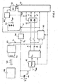
- Fig. 1 a simplified schematic representation of a transponder is shown.
- a base station 100 which is connectable to the transponder via an air interface.
- the base station 100 transmits an alternating magnetic field 120, which can be received by the transceiver circuit 20 with a transponder coil L t .
- the received energy of the alternating magnetic field 120 is converted into a charging current I C , which charges a capacitor C buf .
- the capacitor C buf is discharged by the discharge current I D.
- the magnetic alternating field 120 also serves for bidirectional data transmission between the transponder and the base station 100.
- the discharge current I D is used to supply a computing unit 10 and further subcircuit 12, 20, 30, 31, 40, 41, 50 with electrical energy.
- a connected to the capacitor C buf voltage regulator 30 is provided which provides a supply voltage Vdd at its output.
- the voltage regulator 30 is connected via a switch 31 to the supply voltage connection of the arithmetic unit 10.
- the arithmetic unit 10 is, for example, a computational core of a microcontroller.
- the capacitor C buf is charged so that the capacitor voltage V C increases. If, on the other hand, the discharge current I D exceeds the charging current I C , the capacitor C buf is discharged so that the capacitor voltage V c drops. The capacitor voltage V c thus depends on the difference between charging current I C and discharge current I D. If the capacitor voltage V C is too low, the arithmetic unit 10 can no longer reliably execute the program routines of a program sequence. The error rate increases with decreasing capacitor voltage V C and can abort the program flow and the Reset the arithmetic unit 10 lead. Unregistered register values of the arithmetic unit 10 are lost during the reset.
- the transponder has a comparison circuit 40.
- the comparison circuit 40 has, for example, a number of comparators.
- An input voltage V in of the comparison circuit 40 is compared by the comparison circuit with a first threshold and a second threshold.
- the first threshold and the second threshold are different.
- the first threshold and the second threshold are in the embodiment of Fig. 1 adjustable.
- the first threshold and the second threshold are each set in a voltage range of the capacitor voltage V C in which the arithmetic unit 10 is still working reliably.
- the first threshold and / or the second threshold hysteresis in order to avoid constantly changing states in case of a fluctuation of the capacitor voltage V C in the region of the respective threshold.
- the operating modes allow the surprising effect that the current drain during operation of the transponder can be optimized as a passive transponder by selectively activating or deactivating specific functionalities of the transponder during operation. The activation or deactivation is dependent on the capacitor voltage V C of the capacitor C buf .
- One or more operating modes for reduced current drain for passive transponder applications serve as early indicators and warnings for the software running in the computing unit 10 of a dangerously low supply voltage Vdd before the capacitor voltage V c drops below a reset threshold. When resetting, all values currently determined in the arithmetic unit 10 go lost.
- a reset of the arithmetic unit 10 is undesirable because the reset forces the arithmetic unit 10 to restart initialization routines and return to the initial state. This in turn requires the base station 100 to again send an initialization signal to the transponder to begin data transmission from the beginning.
- the comparison circuit 40 is connected via a switchable inverter 12 to inputs of the arithmetic unit 10, which allow an interruption of the program flow in the arithmetic unit 10.
- the first threshold is the output signal A and the second threshold associated with the output signal B.
- the switchable inverter 12 the output signal A can be inverted or not inverted in response to the control signal D.
- the output signal B can be inverted or not inverted in response to the control signal D.
- the switched output signals A 'and B' are applied to the inputs of the arithmetic unit 10.
- Fig. 1 are the connections between the comparison circuit 40 and the.
- Arithmetic unit 10 executed in triplicate, so that three input signals V in three channels can be monitored simultaneously with the same or different first and second thresholds.
- comparison circuit 40 is connected to at least one output of the arithmetic unit 10.
- the comparison circuit 40 is formed with adjustable thresholds, so that at least one threshold is adjustable by the arithmetic unit 10 and in particular changeable during operation of the transponder.
- the comparison circuit 40 may further comprise a multiplexer 41 to switch a plurality of voltages to be monitored to the input V in .
- a multiplexer 41 to switch a plurality of voltages to be monitored to the input V in .
- Fig. 1 is an entrance of the Multiplexer 41 with the capacitor C buf and another input connected to a battery 21, so that the battery voltage V bat can be monitored.
- a number of further inputs of the multiplexer 41 may be provided. For example, a voltage proportional to the amplitude of the alternating magnetic field can be monitored (in FIG Fig. 1 not shown).
- the battery 21 to charge the battery 21 to the capacitor C buf connectable. The connection is advantageously carried out as a function of the current operating mode. For example, the battery 21 is charged only when the capacitor voltage V C is above the first threshold, since then a sufficient energy transfer from the base station 100 is ensured to the transponder.
- the switch 31 of the embodiment of Fig. 1 is connected to the battery 21 and the voltage regulator 30 and allows switching between a power supply from the capacitor C buf and the charging current I C and a power supply from the battery V bat .
- the switch 31 is formed for example by two alternately switchable field effect transistors.
- a control circuit 50 is provided, whose output is connected to the switch 31 and to read the switching state to the arithmetic unit 10. Furthermore, inputs of the control circuit 50 are connected to the arithmetic unit 10 and / or the output of the comparison circuit 40.
- control circuit 50 Another input of the control circuit 50 is connected to the transmission-reception circuit 20. This allows the switch-on circuit 20 to switch 31 when the transmission is active and the received energy is sufficient for the program flow in the arithmetic unit 10.
- the connection of the control circuit 50 to the arithmetic unit 10 allows the software of the arithmetic unit 10 to directly control the switch 31 when the mode of operation is identified.
- control circuit 50 is connected to the comparison circuit 40 such that by means of a signal of the comparison circuit 40 is switched directly between the capacitor voltage V C and battery voltage V bat . This function is only activated if the battery voltage V bat is available.
- a reset logic 60 is connected via an OR gate 61 to a reset input RST of the arithmetic unit 10. If the voltage supply Vdd of the arithmetic unit 10 is too low, so that undefined states can arise, the arithmetic unit 10 is reset by the reset logic 60 applying a reset signal to the reset input RST of the arithmetic unit 10 via the OR gate 61. Thereafter, the arithmetic unit 10 is reinitialized and all routines are restarted. Likewise the data transmission with the base station 100 must be started from the beginning.
- the OR gate 61 is connected to the control circuit 50, so that by an input signal to the control circuit 50 by the arithmetic unit 10 itself and / or by the comparison circuit 40 and / or by the transmit-receive circuit 20, a reset of the arithmetic unit 10 initiated could be.
- the invention is not limited to the illustrated embodiment of the transponder in Fig. 1 limited.
- the invention includes a variety of different modifications.
- the battery 21, the voltage regulator 30, the switch 31, the control circuit 50, the inverter 12, the OR gate 61, the reset logic 60 and / or the multiplexer 41 may be omitted.
- Fig. 1 Fixed, non-adjustable thresholds can be used.
- transponder circuit according to Fig. 1 can be used particularly advantageously for a motor vehicle key, wherein transmission conditions for the alternating magnetic field 120 varies greatly with time.
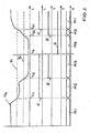
- Fig. 2 is a diagram with a functionality of a voltage monitoring for a transponder by the mapping of multiple waveforms shown schematically.
- the quantities V in , A ', B' and D refer to the corresponding quantities in Fig. 1 , Alternatively, however, another than the one in Fig. 1 shown.
- Transponder circuit with an in Fig. 2 shown functionality can be used.
- the upper part of the diagram shows the variation of the input voltage V in to be compared with respect to a first threshold V 1 and a second threshold V 2 .
- the time is plotted with respect to all signals.
- the arithmetic unit 10 processes a number of routines in the program sequence in the associated first operating mode M1, the routines having a different prioritization.
- the signal A changes to a second operating mode M2.
- the second operating mode M2 may also be referred to as a low power mode. In this second mode of operation M2, a number of low priority routines are stopped and a number of high priority routines are continued. Therefore, at least one routine of low prioritization is stopped and at least one routine of high prioritization is continued.
- Routines of high prioritization are, for example, routines whose register values must be saved. These register values are needed to read the stored register values back into register after a voltage dip - if the capacitor voltage V ln is again sufficient to continue the routines - and to continue the program sequence. This causes the surprising effect that a communication does not have to be completely carried out again after a connection abort, but a continuation of the communication is enabled according to the state before the connection abort.
- low priority routines are stopped. This causes the surprising effect that the period in which reliable execution of the program routines of the program sequence is possible is extended. This is achieved by the capacitor voltage V C, even without a charging current I C , ie slower without magnetic alternating field. The error rate is reduced.
- the current drain from the capacitor C buf can surprisingly be significantly reduced by the computing unit 10. This lengthens the time between the two times t 11 and t 12 and thus the length of the operating mode M2.
- the arithmetic unit 10 changes to a third operating mode M3.
- This third mode of operation M3 may also be referred to as a sleep mode.
- the input voltage V in can decrease to such an extent that no further operation in the arithmetic unit 10 can take place, or it can occur in the arithmetic unit 10 undefined states arise. In this case, a reset can be carried out so that all register values in the arithmetic unit 10 are deleted.
- the switchable inverter 12 is switched at the time t 3 with the signal D, so that the signal A 'is now inverted to the signal A and so that the signal B' is now inverted to the signal B.
- Falling edges of the signals A and B could also be used to interrupt the program sequence in the arithmetic unit 10.
- the input voltage V in rises again above the first threshold V 1 .
- the arithmetic unit 10 can subsequently start all the high and low priority routines again in the operating mode M1.
- the signal D is again set to a low value in the first operating mode M1 (not shown).
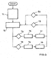
- Fig. 3 shows a simplified schematic flowchart of a program flow in the computing unit 10 with monitoring of the capacitor voltage V C.
- the capacitor C buf is loaded in the program part 71 and the data input at the transponder is checked.
- the arithmetic unit 10 is reset and an initialization routine is started.
- routine part 72 all higher and lower priority routines are started in a first mode of operation. Falling below a first threshold, a first interrupt signal 73 is generated and the program flow is interrupted. The fixed or dynamic address of the interrupt routine is loaded. Subsequently, the program flow is continued in a second operating mode in the program part 71.
- a second interrupt signal 74 is generated and the fixed or dynamic address of the interrupt routine is loaded.
- the arithmetic unit 10 in a third operating mode - a sleep mode - offset. In the third mode of operation, after execution of the last instructions, all routines may be suspended to continue with restored power.
- the program flow returns to the program portion 72, with the execution of the higher priority routines and the low priority routines back.
- the invention is not based on the embodiment of a process sequence Fig. 3 limited. In this way, it is easy for the person skilled in the art to derive other program flows which nevertheless have the monitoring function of the two thresholds for the three operating modes.
- the four interrupt signals may also be dynamically assigned four different and variable thresholds depending on the address within the program flow. It is also possible to provide further thresholds beyond the two thresholds in order, for example, to control the current drain by the arithmetic unit in several increments.
Abstract
Description
Die vorliegende Erfindung betrifft einen Transponder und ein Verfahren zum Betrieb eines Transponders und eine Verwendung für einen Transponder.The present invention relates to a transponder and a method for operating a transponder and a use for a transponder.
Die
Auf eine derartige Transponder-Kommunikationseinrichtung mit einem Transponder wird auch im Dokument
Ein weiteres Beispieldokument ist die
Aus der
Ein Verfahren zur Übertragung von Daten zwischen einer Basisstation und einem passiven Transponder ist aus der Druckschrift
Der Erfindung liegt die Aufgabe zu Grunde, ein Verfahren anzugeben, das die Energieversorgung eines Transponders möglichst verbessert.The invention is based on the object to provide a method that improves the power supply of a transponder as possible.
Diese Aufgabe wird durch ein Verfahren mit den Merkmalen des unabhängigen Patentanspruchs 1 gelöst. Vorteilhafte Weiterbildungen sind Gegenstand von abhängigen Ansprüchen.This object is achieved by a method having the features of independent patent claim 1. Advantageous developments are the subject of dependent claims.
Demzufolge ist ein Verfahren zum Betrieb eines Transponders vorgesehen. Der Transponder weist einen Kondensator zur Speicherung von über eine Luftschnittstelle übertragener Energie und eine mit der gespeicherten Energie versorgbare Recheneinheit auf. Wird der Transponder mit über eine Luftschnittstelle übertragener Energie versorgt, wird ein derartiger Transponder auch als passiver Transponder bezeichnet. Zusätzlich kann der Transponder eine eigene Energieversorgung - wie beispielsweise eine aufladbare oder nicht-aufladbare Batterie - aufweisen.Accordingly, a method for operating a transponder is provided. The transponder has a capacitor for storing energy transmitted via an air interface and a computer unit that can be supplied with the stored energy. If the transponder is supplied with energy transmitted via an air interface, such a transponder is also referred to as a passive transponder. In addition, the transponder can have its own power supply - such as a rechargeable or non-rechargeable battery.
In dem Verfahren wird eine Kondensatorspannung des Kondensators mit einer ersten Schwelle verglichen. Zum Vergleich kann beispielsweise ein Komparator verwendet werden. Hierzu wird beispielsweise die Spannung des Kondensators abgetastet und analog-digital gewandelt. Alternativ kann auch ein Analogkomparator verwendet werden, der einen kontinuierlichen Vergleich ermöglicht. Weiterhin wird die Kondensatorspannung mit einer zweiten Schwelle verglichen, wobei sich die erste Schwelle und die zweite Schwelle unterscheiden. Auch zum Vergleich der Kondensatorspannung mit der zweiten Schwelle kann beispielsweise ein Komparator verwendet werden. Der Vergleich mit der ersten Schwelle und mit der zweiten Schwelle kann zeitlich disjunkt, vorzugsweise jedoch gleichzeitig erfolgen.In the method, a capacitor voltage of the capacitor is compared to a first threshold. For comparison, for example, a comparator can be used. For this purpose, for example, the voltage of the capacitor is sampled and converted analog-digital. Alternatively, an analog comparator can be used, which allows a continuous comparison. Furthermore, the capacitor voltage is compared with a second threshold, wherein the first threshold and the second threshold differ. Also, for comparison of the capacitor voltage with the second threshold, for example, a comparator can be used. The comparison with the first threshold and with the second threshold may be disjoint in time, but preferably at the same time.
Vorzugsweise führt die Recheneinheit in einem ersten Betriebsmodus eine Anzahl von Routinen mit unterschiedlicher Priorisierung aus. Der erste Betriebsmodus ist dabei definiert, wenn die Kondensatorspannung oberhalb der ersten Schwelle ist. Dabei ist unter der Kondensatorspannung der Betrag zu verstehen, so dass es unerheblich ist, ob die Kondensatorspannung als positive oder negative Spannung betrachtet wird. Der Betriebsmodus wird vorzugsweise von der Recheneinheit festgelegt, indem beispielsweise bestimmte Werte oder Parameter eingestellt werden.In a first operating mode, the arithmetic unit preferably executes a number of routines with different prioritization. The first operating mode is defined when the capacitor voltage is above the first threshold. Here, by the capacitor voltage is meant the amount, so that it is irrelevant whether the capacitor voltage is considered positive or negative voltage. The operating mode is preferably determined by the arithmetic unit, for example by setting certain values or parameters.
Der Betriebsmodus ist vorzugsweise abhängig von der vorteilhafterweise durch einen Komparator detektierten Kondensatorspannung. Vorzugsweise wird ein der Detektion zugeordnetes oder kodiertes Signal an die Recheneinheit übertragen. Das Signal ist beispielsweise ein Detektions-Status-Flag oder ein Unterbrechungssignal (IRQ - engl. interrupt request). Vorteilhafterweise wird ein innerhalb der Recheneinheit programmiertes Statusregister entsprechend der Detektion innerhalb eines Softwareprogramms aktualisiert. Hierdurch werden vorteilhafterweise eine Nachverfolgung des Betriebsmodus und eine Steuerung von Funktionalitäten der Recheneinheit oder des Transponders ermöglicht.The operating mode is preferably dependent on the capacitor voltage advantageously detected by a comparator. Preferably, a signal associated with the detection or coded is transmitted to the arithmetic unit. The signal is, for example, a detection status flag or interrupt signal (IRQ). Advantageously, a status register programmed within the arithmetic unit is updated according to the detection within a software program. As a result, a tracking of the operating mode and a control of functionalities of the arithmetic unit or the transponder are advantageously made possible.
Vorzugsweise wird in einem zweiten Betriebsmodus eine Anzahl von Routinen mit niedriger Priorisierung gestoppt und eine Anzahl von Routinen mit hoher Priorisierung fortgeführt. Dies erfolgt unter der Bedingung, dass die Kondensatorspannung zwischen der ersten Schwelle und der zweiten Schwelle ist. Vorzugsweise weisen Routinen - beispielsweise Unterbrechungsroutinen (IRQ) - die der zweiten Schwelle zugeordnet sind eine höhere Priorität auf als Routinen, die der ersten Schwell zugeordnet sind. Routinen höherer Priorisierung können beispielweise Unterbrechungen des Programmablaufs vorbelegen, die sonst Routinen niederer Priorisierung zugeordnet sind.Preferably, in a second mode of operation, a number of low priority routines are stopped and a number of high priority routines are continued. This is done under the condition that the capacitor voltage is between the first threshold and the second threshold. Preferably, routines - such as interrupt routines (IRQ) - associated with the second threshold have a higher priority than routines associated with the first threshold. Routines of higher prioritization can for example pre-allocate interruptions of the program sequence which are otherwise assigned to routines of lower prioritization.
Gemäß einer vorteilhaften Weiterbildung erfolgt in einem dritten Betriebmodus ein Aussetzen (engl. suspend) der Routinen der Recheneinheit. Das Aussetzen erfolgt unter der Bedingung, dass die Kondensatorspannung unterhalb der zweiten Schwelle ist. Dabei sind Registerwerte der Routinen beispielsweise in einem nicht-flüchtigen Speicher (EEPROM, FRAM etc.) gespeichert und die Werte können nach dem Aussetzen wieder in Register eingeladen werden.According to an advantageous development, in a third operating mode, a suspension of the routines of the arithmetic unit takes place. The exposure occurs under the condition that the capacitor voltage is below the second threshold. In this case, register values of the routines are stored, for example, in a non-volatile memory (EEPROM, FRAM, etc.) and the values can be reloaded into registers after exposure.
In einer bevorzugten Weiterbildung ist vorgesehen, dass zumindest die zuvor ausgesetzten Routinen fortgesetzt werden, wenn die Kondensatorspannung erneut oberhalb der ersten Schwelle oder bereits oberhalb der zweiten Schwelle ist. Wird die Recheneinheit zurückgesetzt, werden zunächst eine Initialisierung gestartet und anschließend die Routinen von ihrem Beginn an abgearbeitet. Hingegen können die ausgesetzten Routinen an einer beliebigen Stellen innerhalb ihres Ablaufs fortgesetzt werden. Vorzugsweise wird zumindest eine der ausgesetzten Routinen an der Stelle innerhalb ihres Ablaufs fortgesetzt, an der sie zuvor ausgesetzt worden ist. Alternativ sind ebenfalls Rücksprünge innerhalb des Ablaufs der jeweiligen Routine möglich. Zum Fortsetzen der Routine wird diese daher nicht neu gestartet oder initialisiert.In a preferred embodiment, it is provided that at least the previously exposed routines are continued when the capacitor voltage is again above the first threshold or already above the second threshold. If the arithmetic unit is reset, an initialization is started first and then the routines are processed from the beginning. On the other hand, the suspended routines can be continued anywhere within their course. Preferably, at least one of the suspended routines will continue at the location within its course to which it has previously been suspended. Alternatively, returns within the course of the respective routine are also possible. Therefore, to continue the routine, it will not be restarted or initialized.
In einer anderen Weiterbildung ist vorgesehen, dass ein Unterschreiten und/oder Überschreiten der ersten Schwelle durch die Kondensatorspannung ein erstes Unterbrechungssignal (engl. interrupt request) zur Unterbrechung des Programmablaufs in der Recheinheit auslöst. Hierzu gelangt das Unterbrechungssignal an einen unterbrechungsfähigen Eingang der Recheneinheit. Das Unterbrechungssignal wird beispielsweise als steigende Flanke eines Digitalsignals generiert. In einer wiederum anderen Weiterbildung ist vorgesehen, dass ein Unterschreiten und/oder Überschreiten der zweiten Schwelle durch die Kondensatorspannung ein zweites Unterbrechungssignal zur Unterbrechung des Programmablaufs in der Recheinheit auslöst.In another development, it is provided that falling below and / or exceeding the first threshold by the capacitor voltage triggers a first interrupt signal (English interrupt request) for interrupting the program sequence in the computing unit. For this purpose, the interrupt signal arrives at an interruptible input of the arithmetic unit. The interrupt signal is generated, for example, as a rising edge of a digital signal. In yet another further development, it is provided that falling below and / or exceeding the second threshold by the capacitor voltage triggers a second interrupt signal for interrupting the program sequence in the computing unit.
Der Erfindung liegt weiterhin die Aufgabe zu Grunde, eine Verwendung für einen Transponder anzugeben, dessen Energieversorgung möglichst verbessert ist.The invention is further based on the object to provide a use for a transponder whose power supply is improved as possible.
Diese Aufgabe wird durch eine Verwendung mit den Merkmalen des unabhängigen Patentanspruchs 6 gelöst. Die Verwendung kann durch Merkmale des Verfahrens oder des Transponders vorteilhaft weitergebildet werden.This object is achieved by a use having the features of independent patent claim 6. The use can be through Characteristics of the method or the transponder are advantageously developed.
Demzufolge ist eine Verwendung von einer ersten Schwelle und einer von der ersten Schwelle verschiedenen zweiten Schwelle zur Überwachung einer Kondensatorspannung eines Kondensators eines Transponders vorgesehen. Der Transponder weist zusätzlich zum Kondensator eine Recheneinheit auf, die mit in dem Kondensator gespeicherter Energie versorgbar ist. Vorzugsweise ist die Recheneinheit zur Reduzierung der Stromaufnahme ausgebildet, wenn die Kondensatorspannung zwischen der ersten Schwelle und der zweiten Schwelle ist.Accordingly, a use of a first threshold and a second threshold different from the first threshold for monitoring a capacitor voltage of a capacitor of a transponder is provided. The transponder has, in addition to the capacitor, a computing unit which can be supplied with energy stored in the capacitor. Preferably, the arithmetic unit is designed to reduce the current consumption when the capacitor voltage is between the first threshold and the second threshold.
Bevorzugt arbeitet die Recheneinheit in einem ersten Betriebsmodus, wenn die Kondensatorspannung oberhalb der ersten Schwelle ist. Der erste Betriebsmodus kann auch als Normalmodus (Normal-Level) bezeichnet werden. In dem ersten Betriebsmodus ist die Funktionalität der Recheneinheit und/oder des Transponders nicht begrenzt.The computing unit preferably operates in a first operating mode when the capacitor voltage is above the first threshold. The first operating mode can also be referred to as normal mode. In the first operating mode, the functionality of the arithmetic unit and / or the transponder is not limited.
Bevorzugt arbeitet die Recheneinheit in einem zweiten Betriebsmodus, wenn die Kondensatorspannung unterhalb der ersten Schwelle und oberhalb einer zweiten Schwelle ist. Der zweite Betriebsmodus kann auch als Warnmodus (Warn-Level) bezeichnet werden. Vorteilhafterweise ist in dem zweiten Betriebsmodus zumindest eine Begrenzung einer Stromentnahme aus dem Kondensator aktiviert. Vorteilhafterweise ist in dem zweiten Betriebsmodus zumindest eine Funktionalität des Transponders deaktiviert um die Stromentnahme aus dem Kondensator zu reduzieren. Vorzugsweise liest eine Firmware periodisch ein innerhalb der Recheneinheit programmiertes Statusregister, das den Betriebsmodus enthält. Vorteilhafterweise werden in Abhängigkeit von einem Wert des Statusregisters Peripherieschaltkreise des Transponders aktiviert beziehungsweise deaktiviert oder eine Taktfrequenz der Recheneinheit wird verändert.The computing unit preferably operates in a second operating mode when the capacitor voltage is below the first threshold and above a second threshold. The second operating mode can also be referred to as a warning mode (warning level). Advantageously, in the second operating mode, at least one limitation of a current drain from the capacitor is activated. Advantageously, in the second operating mode, at least one functionality of the transponder is deactivated in order to reduce the current drain from the capacitor. Preferably, firmware periodically reads a status register programmed within the arithmetic unit that contains the operating mode. Advantageously, depending on a value of the status register, peripheral circuits of the transponder are activated or deactivated or a clock frequency of the arithmetic unit is changed.
Bevorzugt arbeitet die Recheneinheit in einem dritten Betriebsmodus, wenn die Kondensatorspannung unterhalb der zweiten Schwelle ist. Der dritte Betriebsmodus kann auch als Notbetriebsmodus (Ausschalt-Level) bezeichnet werden. Vorteilhafterweise ist in dem dritten Betriebsmodus der überwiegende Teil der Funktionalität des Transponders deaktiviert. Nur eine geringe Ladung ist in dem Kondensator verblieben. Die Recheneinheit wechselt vorteilhafterweise in einen Schlafzustand. Hierzu werden vorzugsweise die Routinen der Recheneinheit ausgesetzt. Die ausgesetzten Routinen an einer beliebigen Stellen innerhalb ihres Ablaufs - beispielsweise an der ausgesetzten Stelle oder einer anderen Stelle durch Rücksprung - fortgesetzt werden, wenn die Kondensatorspannung zumindest oberhalb der zweiten Schwelle ist.Preferably, the arithmetic unit operates in a third mode of operation when the capacitor voltage is below the second threshold. The third operating mode may also be referred to as an emergency operating mode (switch-off level). Advantageously, the majority of the functionality of the transponder is deactivated in the third operating mode. Only a small charge has remained in the capacitor. The arithmetic unit advantageously changes to a sleep state. For this purpose, preferably the routines of the arithmetic unit are suspended. The suspended routines may be continued at any point within their course - for example, at the exposed point or elsewhere by return - when the capacitor voltage is at least above the second threshold.
Bevorzugt ist zusätzlich unterhalb der zweiten Schwelle eine dritte Schwelle vorgesehen. Vorzugsweise wird die Recheneinheit zurückgesetzt, wenn die Kondensatorspannung die dritte Schwelle unterschreitet (Reset-Level). Beispielsweise kann die Kondensatorspannung im dritten Betriebsmodus trotz der Deaktivierung des überwiegenden Teils der Funktionalität des Transponders durch eine sehr geringe Stromentnahme aus dem Kondensator weiter absinken und die dritte Schwelle unterschreiten. Vorteilhafterweise erfolgt dann ein Zurücksetzen der Recheneinheit, um undefinierte Zustände zu vermeiden. Steigt die Kondensatorspannung nach dem Zurücksetzen erneut an, wird die Recheneinheit zunächst initialisiert und danach werden alle Routinen neu begonnen.Preferably, a third threshold is additionally provided below the second threshold. Preferably, the arithmetic unit is reset when the capacitor voltage falls below the third threshold (reset level). For example, the capacitor voltage in the third operating mode, despite the deactivation of the majority of the functionality of the transponder by a very low current drain from the capacitor continue to fall and fall below the third threshold. Advantageously, then a reset of the arithmetic unit to avoid undefined states. If the capacitor voltage rises again after the reset, the arithmetic unit is first initialized and then all routines are restarted.
Der Erfindung liegt weiterhin die Aufgabe zu Grunde, einen Transponder anzugeben, dessen Energieversorgung möglichst verbessert ist.The invention is further based on the object to provide a transponder whose power supply is improved as possible.
Diese Aufgabe wird durch einen Transponder mit den Merkmalen des unabhängigen Patentanspruchs 7 gelöst. Vorteilhafte Weiterbildungen sind Gegenstand von abhängigen Ansprüchen.This object is achieved by a transponder having the features of independent patent claim 7. Advantageous developments are the subject of dependent claims.
Demzufolge ist ein Transponder mit einem Sende-Empfangs-Schaltkreis, mit einem Kondensator, mit einer Recheneinheit und mit einem Vergleichsschaltkreis vorgesehen. Der Kondensator ist zum Laden mit dem Sende-Empfangs-Schaltkreis verbunden. Die Recheneinheit ist zur Energieversorgung mit dem Kondensator verbunden. Vorzugsweise ist die Recheneinheit direkt oder indirekt mit dem Sende-Empfangs-Schaltkreis zur Übertragung von Daten verbunden.Accordingly, a transponder is provided with a transmit-receive circuit, with a capacitor, with a computing unit and with a comparison circuit. The capacitor is connected to the transceiver circuit for charging. The arithmetic unit is connected to the power supply to the capacitor. Preferably, the arithmetic unit is directly or indirectly connected to the transceiver circuit for transmitting data.
Der Vergleichsschaltkreis ist mit dem Kondensator verbunden. Weiterhin ist die Recheneinheit mit dem Vergleichsschaltkreis verbunden. Der Vergleichsschaltkreis ist eingerichtet eine Kondensatorspannung des Kondensators mit einer ersten Schwelle und mit einer von der ersten Schwelle verschiedenen zweiten Schwelle zu vergleichen. Bevorzugt ist die Kondensatorspannung als Eingangsgröße an einen Eingang des Vergleichsschaltkreises anlegbar.The comparison circuit is connected to the capacitor. Furthermore, the arithmetic unit is connected to the comparison circuit. The comparison circuit is arranged to compare a capacitor voltage of the capacitor with a first threshold and with a second threshold different from the first threshold. Preferably, the capacitor voltage can be applied as an input to an input of the comparison circuit.
In einer vorteilhaften Weiterbildung weist die erste Schwelle und/oder die zweite Schwelle eine Hysterese auf. Vorzugsweise weist der Vergleichsschaltkreis für die erste Schwelle einen ersten Fensterkomparator oder Schmitt-Trigger und/oder für die zweite Schwelle einen zweiten Fensterkomparator oder Schmitt-Trigger auf. Die Hysterese weist ein Spannungsfenster in Bezug auf die Kondensatorspannung auf, in dem der Betriebsmodus nicht verändert wird. Wird beispielsweise für die erste Schwelle deren unterer Hystereselevel unterschritten, wechselt die Recheneinheit beispielsweise von dem ersten Betriebsmodus in den zweiten Betriebsmodus. Steigt danach die Kondensatorspannung beispielsweise geringfügig an, wobei der obere Hystereselevel der ersten Schwelle noch nicht überschritten wird, so verbleibt die Recheneinheit im zweiten Betriebsmodus. Erst mit Überschreiten des oberen Hystereselevels durch die Kondensatorspannung erzeugt der Vergleichsschaltkreis ein Signal, dass beispielsweise den Programmablauf der Recheneinheit unterbricht, so dass die Recheneinheit zurück in den ersten Betriebsmodus wechseln kann.In an advantageous development, the first threshold and / or the second threshold have a hysteresis. The comparison circuit for the first threshold preferably has a first window comparator or Schmitt trigger and / or a second window comparator or Schmitt trigger for the second threshold. The hysteresis has a voltage window with respect to the capacitor voltage, in which the operating mode is not changed. If, for example, the lower threshold hysteresis level is reached for the first threshold, the arithmetic unit changes, for example, from the first operating mode to the second operating mode. If, for example, the capacitor voltage then rises slightly, with the upper hysteresis level of the first threshold not yet exceeded, then the arithmetic unit remains in the second operating mode. Only when the upper hysteresis level is exceeded by the capacitor voltage of the comparison circuit generates a signal that interrupts, for example, the program flow of the arithmetic unit, so that the arithmetic unit can switch back to the first operating mode.
Die Recheneinheit ist vorzugsweise eingerichtet eine Anzahl von Routinen mit unterschiedlicher Priorisierung innerhalb ihres Programmablaufs auszuführen.The arithmetic unit is preferably set up to execute a number of routines with different prioritization within their program sequence.
Gemäß einer bevorzugten Weiterbildung ist die Recheneinheit eingerichtet in Abhängigkeit von einem Ausgangssignal des Vergleichsschaltkreises eine Anzahl von Routinen mit niedriger Priorisierung zu stoppen und eine Anzahl von Routinen mit hoher Priorisierung fortzuführen. Alternativ oder in Kombination zum Stoppen der Routinen mit niedriger Priorisierung ist in einer anderen vorteilhaften Weiterbildung die Rechneinheit eingerichtet in Abhängigkeit von dem Ausgangssignal des Vergleichsschaltkreises periphere Schaltkreise von der Stromversorgung aus dem Kondensator abzuschalten oder die Frequenz des Taktsignals der Recheneinheit zu reduzieren.According to a preferred development, the arithmetic unit is set up in response to an output signal of the comparison circuit to stop a number of low priority routines and to continue a number of high priority routines. Alternatively or in combination for stopping the routines with low prioritization, in another advantageous development the computer unit is set up in dependence on the output signal of the comparison circuit to disconnect peripheral circuits from the power supply from the capacitor or to reduce the frequency of the clock signal of the arithmetic unit.
In einer vorteilhaften Weiterbildung weist der Transponder zusätzlich eine Batterie und einen Schalter auf. Der Schalter ist mit der Batterie und mit dem Kondensator zum Umschalten der Energieversorgung zwischen Batterie und Kondensator verbunden. Die Batterie ist beispielsweise aufladbar.In an advantageous development, the transponder additionally has a battery and a switch. The switch is connected to the battery and to the capacitor for switching the power supply between the battery and the capacitor. The battery is rechargeable, for example.
Vorzugsweise ist die Recheneinheit zur Steuerung der Umschaltung der Energieversorgung in Abhängigkeit von einem Ausgangssignal des Vergleichsschaltkreises eingerichtet. Alternativ kann zur Steuerung der Umschaltung auch ein weiterer Teilschaltkreis des Transponders vorgesehen sein.Preferably, the arithmetic unit is arranged to control the switching of the power supply in response to an output signal of the comparison circuit. Alternatively, a further subcircuit of the transponder may be provided to control the switching.
Gemäß einer besonders bevorzugten Weiterbildung sind die erste Schwelle und/oder die zweite Schwelle des Vergleichsschaltkreises einstellbar. Die Einstellung kann dabei durch ein Signal über den Sende-Empfangs-Schaltkreis oder durch eine Steuerung der Recheneinheit erfolgen. Vorzugsweise erfolgt die Einstellung der ersten und/oder zweiten Schwelle dynamisch beispielsweise in Abhängigkeit von Randbedingung des Transponders. Vorteilhafterweise ist auch eine selbstlernende Einstellung, beispielsweise mittels Auswertung durch die Recheneinheit möglich.According to a particularly preferred embodiment, the first threshold and / or the second threshold of the comparison circuit are adjustable. The setting can be effected by a signal via the transmit-receive circuit or by a control of the arithmetic unit. Preferably, the setting of the first and / or second threshold dynamically, for example, depending on the boundary condition of the transponder. Advantageously, a self-learning setting, for example by means of evaluation by the arithmetic unit is possible.
In einer anderen Weiterbildung ist vorgesehen, dass die Recheneinheit zur Einstellung der ersten Schwelle und/oder der zweiten Schwelle ausgebildet und mit einem Steuereingang des Vergleichsschaltkreises verbunden ist.In another embodiment, it is provided that the arithmetic unit for setting the first threshold and / or the second threshold is formed and connected to a control input of the comparison circuit.
Vorzugsweise weist der Vergleichsschaltkreis einen Multiplexer auf. Ein erster Eingang des Multiplexers ist mit dem Kondensator und ein zweiter Eingang des Multiplexers ist mit einer Batterie, insbesondere zur Messung der Batteriespannung, verbunden.Preferably, the comparison circuit has a multiplexer. A first input of the multiplexer is connected to the capacitor and a second input of the multiplexer is connected to a battery, in particular for measuring the battery voltage.
Die zuvor beschriebenen Weiterbildungsvarianten sind sowohl einzeln als auch in Kombination besonders vorteilhaft. Dabei können sämtliche Weiterbildungsvarianten untereinander auch unter verschiedenen Anspruchskategorien kombiniert werden. Einige mögliche Kombinationen sind in der Beschreibung der Ausführungsbeispiele der Figuren erläutert. Diese dort dargestellten Möglichkeiten von Kombinationen der Weiterbildungsvarianten sind jedoch nicht abschließend.The further development variants described above are particularly advantageous both individually and in combination. All training variants can be combined with each other under different categories of claims. Some possible combinations are explained in the description of the embodiments of the figures. However, these possibilities of combinations of further development variants presented there are not exhaustive.
Im Folgenden wird die Erfindung durch Ausführungsbeispiele anhand zeichnerischer Darstellungen näher erläutert.In the following the invention will be explained in more detail by exemplary embodiments with reference to drawings.
Dabei zeigen
- Fig. 1
- eine schematische Darstellung eines Transpondersystems,
- Fig. 2
- ein schematisches Diagramm, und
- Fig. 3
- einen schematischen Verfahrensablauf.
- Fig. 1
- a schematic representation of a transponder system,
- Fig. 2
- a schematic diagram, and
- Fig. 3
- a schematic procedure.
In
Der Entladestrom ID dient der Versorgung einer Recheneinheit 10 und weiterer Teilschaltkreises 12, 20, 30, 31, 40, 41, 50 mit elektrischer Energie. Hierzu ist ein mit dem Kondensator Cbuf verbundener Spannungsregler 30 vorgesehen, der an seinem Ausgang eine Versorgungsspannung Vdd bereitstellt. Zur Versorgung der Recheneinheit 10 als Hauptstromverbraucher ist der Spannungsregler 30 über einen Schalter 31 mit dem Versorgungsspannungsanschluss der Recheneinheit 10 verbunden. Die Recheneinheit 10 ist beispielsweise ein Rechenkern eines Mikrocontrollers.The discharge current I D is used to supply a
Übersteigt der Ladestrom IC den Entladestrom ID wird der Kondensator Cbuf geladen, so dass die Kondensatorspannung VC steigt. Übersteigt hingegen der Entladestrom ID den Ladestrom IC wird der Kondensator Cbuf entladen, so dass die Kondensatorspannung Vc fällt. Die Kondensatorspannung Vc hängt somit von der Differenz zwischen Ladestrom IC und Entladestrom ID ab. Ist die Kondensatorspannung VC zu niedrig kann die Recheneinheit 10 die Programmroutinen eines Programmablaufs nicht mehr zuverlässig abarbeiten. Die Fehlerhäufigkeit steigt mit abnehmender Kondensatorspannung VC an und kann zum Abbruch des Programmablaufs und zum Zurücksetzen der Recheneinheit 10 führen. Nicht gespeicherte Registerwerte der Recheneinheit 10 gehen beim Zurücksetzen verloren.If the charging current I C exceeds the discharge current I D , the capacitor C buf is charged so that the capacitor voltage V C increases. If, on the other hand, the discharge current I D exceeds the charging current I C , the capacitor C buf is discharged so that the capacitor voltage V c drops. The capacitor voltage V c thus depends on the difference between charging current I C and discharge current I D. If the capacitor voltage V C is too low, the
Um die Verfügbarkeit der Recheneinheit der
Für die Recheneinheit 10 des Ausführungsbeispiels der
Im Ausführungsbeispiel der
Durch den schaltbaren Inverter 12 kann in Abhängigkeit von dem Steuersignal D das Ausgangssignal B invertiert oder nicht invertiert werden. Die geschalteten Ausgangssignale A' beziehungsweise B' liegen an den Eingängen der Recheneinheit 10 an. Im Ausführungsbeispiel der
Weiterhin ist der Vergleichsschaltkreis 40 mit zumindest einem Ausgang der Recheneinheit 10 verbunden. Der Vergleichsschaltkreis 40 ist mit einstellbaren Schwellen ausgebildet, so dass zumindest eine Schwelle durch die Recheneinheit 10 einstellbar und insbesondere im Betrieb des Transponders änderbar ist.Furthermore, the
Der Vergleichschaltkreis 40 kann weiterhin einen Multiplexer 41 aufweisen um mehrere zu überwachende Spannungen auf den Eingang Vin zu schalten. In dem Ausführungsbeispiel der
Der Schalter 31 des Ausführungsbeispiels der
Ein weiterer Eingang des Kontrollschaltkreises 50 ist mit dem Sende-Empfangs-Schaltkreis 20 verbunden. Dies ermöglicht, dass der dem Sende-Empfangs-Schaltkreis 20 den Schalter 31 schaltet, wenn die Übertragung aktiv ist und die empfangene Energie für den Programmablauf in der Recheneinheit 10 ausreicht. Die Verbindung des Kontrollschaltkreises 50 mit der Recheneinheit 10 ermöglicht es, dass die Software der Recheneinheit 10 den Schalter 31 direkt steuert, wenn der Betriebsmodus identifiziert ist.Another input of the
Weiterhin ist der Kontrollschaltkreise 50 derart mit dem Vergleichsschaltkreis 40 verbunden, dass mittels eines Signals der Vergleichsschaltkreis 40 direkt zwischen Kondensatorspannung VC und Batteriespannung Vbat umgeschaltet wird. Diese Funktion ist nur aktiviert, wenn die Batteriespannung Vbat zur Verfügung steht.Furthermore, the
Eine Rücksetzlogik 60 ist über ein Oder-Gatter 61 mit einem Reseteingang RST der Recheneinheit 10 verbunden. Ist die Spannungsversorgung Vdd der Recheneinheit 10 zu niedrig, so dass undefinierte Zustände entstehen können, wird die Recheneinheit 10 zurückgesetzt, indem die Rücksetzlogik 60 über das Oder-Gatter 61 ein Rücksetzsignal an den Reseteingang RST der Recheneinheit 10 anlegt. Danach wird die Recheneinheit 10 neu initialisiert und alle Routinen werden neu gestartet. Ebenfalls die Datenübertragung mit der Basisstation 100 muss von vorne gestartet werden. Ebenfalls ist das Oder-Gatter 61 mit dem Kontrollschaltkreis 50 verbunden, so dass durch ein Eingangssignal am Kontrollschaltkreis 50 durch die Recheneinheit 10 selbst und/oder durch den Vergleichsschaltkreis 40 und/oder durch den Sende-Empfangs-Schaltkreis 20 ein Rücksetzen der Recheneinheit 10 initiiert werden könnte.A
Die Erfindung ist dabei nicht auf die dargestellte Ausgestaltung des Transponders in
Die Funktionalität des Transponder-Schaltkreises gemäß
In
Im oberen Teil des Diagramms ist der Verlauf der zu vergleichenden Eingangsspannung Vin in Bezug zu einer ersten Schwelle V1 und einer zweiten Schwelle V2 dargestellt. Auf der Abszisse ist bezüglich aller Signale die Zeit aufgetragen.The upper part of the diagram shows the variation of the input voltage V in to be compared with respect to a first threshold V 1 and a second threshold V 2 . On the abscissa the time is plotted with respect to all signals.
Von Beginn der Darstellung bis zum Zeitpunkt t11 ist die Spannung Vin oberhalb der ersten Schwelle V1. Die Recheneinheit 10 arbeitet im zugehörigen ersten Betriebsmodus M1 eine Anzahl von Routinen im Programmablauf ab, wobei die Routinen eine unterschiedliche Priorisierung aufweisen.From the beginning of the display until the time t 11 , the voltage V in is above the first threshold V 1 . The
Zum Zeitpunkt t11 unterschreitet die Spannung Vin die erste Schwelle V1. Das Signal A' wechselt vom Wert Low auf den Wert High. Die positive Flanke des Signals A' löst eine Unterbrechung des Programmablauf in der Recheneinheit 10 aus. Aufgrund dieser Unterbrechung wechselt die Recheneinheit 10 in einen zweiten Betriebsmodus M2. Der zweite Betriebsmodus M2 kann auch als Niedrigleistungsmodus bezeichnet werden. In diesem zweiten Betriebsmodus M2 werden eine Anzahl von Routinen mit niedriger Priorisierung gestoppt und eine Anzahl von Routinen mit hoher Priorisierung fortgeführt. Es wird daher zumindest eine Routine niedriger Priorisierung gestoppt und zumindest eine Routine hoher Priorisierung fortgeführt.At time t 11 falls below the voltage V in the first threshold V1. The signal A 'changes from the value Low to the value High. The positive edge of the signal A 'triggers an interruption of the program sequence in the
Routinen hoher Priorisierung sind beispielsweise Routinen, deren Registerwerte gesichert werden müssen. Diese Registerwerte werden benötigt um nach einem Spannungseinbruch - wenn die Kondensatorspannung Vln wieder ausreicht die Routinen fortzuführen - die gespeicherten Registerwerte wieder in Register einzulesen und den Programmablauf fortzusetzen. Dies bewirkt den überraschenden Effekt, dass eine Kommunikation auch nach einem Verbindungsabbruch nicht erneut vollständig durchgeführt werden muss, sondern ein Fortsetzen der Kommunikation entsprechend dem Zustand vor dem Verbindungsabbruch ermöglicht wird.Routines of high prioritization are, for example, routines whose register values must be saved. These register values are needed to read the stored register values back into register after a voltage dip - if the capacitor voltage V ln is again sufficient to continue the routines - and to continue the program sequence. This causes the surprising effect that a communication does not have to be completely carried out again after a connection abort, but a continuation of the communication is enabled according to the state before the connection abort.
Im Gegensatz zu Routinen hoher Priorisierung werden Routinen niederer Priorisierung gestoppt. Dies bewirkt den überraschenden Effekt, dass die Zeitspanne, in der eine zuverlässige Abarbeitung der Programmroutinen des Programmablaufs möglich ist, verlängert wird. Dies wird erzielt, indem die Kondensatorspannung VC auch ohne einen Ladestrom IC, d.h. ohne magnetisches Wechselfeld, langsamer sinkt. Die Fehlerhäufigkeit wird reduziert. Durch die Priorisierung der Routinen und das Stoppen von Routinen niederer Priorität kann die Stromentnahme aus dem Kondensator Cbuf durch die Recheneinheit 10 überraschenderweise deutlich reduziert werden. Hierdurch verlängert sich die Zeitdauer zwischen den zwei Zeitpunkten t11 und t12 und somit die Länge des Betriebsmodus M2.Unlike high priority routines, low priority routines are stopped. This causes the surprising effect that the period in which reliable execution of the program routines of the program sequence is possible is extended. This is achieved by the capacitor voltage V C, even without a charging current I C , ie slower without magnetic alternating field. The error rate is reduced. By prioritizing the routines and stopping low-priority routines, the current drain from the capacitor C buf can surprisingly be significantly reduced by the
Zum Zeitpunkt t12 unterschreitet die Spannung Vin die zweite Schwelle V2, so dass das Signal B' von einem Low-Wert auf einen High-Wert wechselt. Die positive Flanke des Signals B' führt wiederum zu einer Unterbrechung des Programmablaufs. Die Recheneinheit 10 wechselt in einen dritten Betriebsmodus M3. Dieser dritte Betriebsmodus M3 kann auch als Schlafmodus bezeichnet werden. Die Eingangsspannung Vin kann in dem dritten Betriebsmodus M3 soweit absinken, dass keine Operation in der Recheneinheit 10 mehr erfolgen kann oder es können in der Recheneinheit 10 undefinierte Zustände entstehen. In diesem Fall kann ein Rücksetzen (engl. reset) erfolgen, so dass alle Registerwerte in der Recheneinheit 10 gelöscht werden. Um nachfolgend ein Ansteigen der Eingangsspannung Vin ebenfalls durch positive Flanken detektieren zu können, wird zum Zeitpunkt t3 mit dem Signal D der schaltbare Inverter 12 geschaltet, so dass das Signal A' nun zum Signal A invertiert ist und so dass das Signal B' nun zum Signal B invertiert ist. Alternativ zum Ausführungsbeispiel der
Steigt zum Zeitpunkt t22 im Ausführungsbeispiel der
Zum Zeitpunkt t21 steigt die Eingangsspannung Vin wieder über die erste Schwelle V1 an. Die Recheneinheit 10 kann nachfolgend im Betriebsmodus M1 wiederum alle Routinen hoher und niedriger Priorität starten. Das Signal D wird im ersten Betriebsmodus M1 wiederum auf einen Low-Wert gesetzt (nicht dargestellt).At time t 21 , the input voltage V in rises again above the first threshold V 1 . The
Wird hingegen die zweite Schwelle unterschritten, wird ein zweites Unterbrechungssignal 74 erzeugt und die feste oder dynamische Adresse der Unterbrechungsroutine wird geladen. Im Programmteil 77 wird die Recheneinheit 10 in einen dritten Betriebsmodus - einen Schlafmodus - versetzt. In dem dritten Betriebsmodus können nach der Abarbeitung der letzten Befehle alle Routinen aussetzen, um diese bei wiederhergestellter Spannungsversorgung fortzusetzen.If, however, the second threshold is undershot, a second interrupt
Durch das Unterbrechungssignal 79, das einem Überschreiben der ersten Schwelle zugeordnet ist, oder durch das Unterbrechungssignal 80, das einem Überschreiben der zweiten Schwelle zugeordnet ist, gelangt der Programmfluss wieder in den Programmteil 72, mit der Ausführung der höher priorisierten Routinen und der nieder priorisierten Routinen zurück.By the interrupt
Die Erfindung ist dabei nicht auf das Ausführungsbeispiel eines Verfahrensablaufs nach
- 1010
- Recheneinheitcomputer unit
- 1212
- schaltbarer Inverterswitchable inverter
- 2020
- Sende-Empfangs-SchaltkreisTransmit-receive circuit
- 2121
- Batteriebattery
- 3030
- Spannungsreglervoltage regulators
- 3131
- Schalterswitch
- 4040
- Vergleichsschaltkreis, KomparatorComparison circuit, comparator
- 4141
- Multiplexer des VergleichsschaltkreisesMultiplexer of the comparison circuit
- 5050
- Kontrollschaltkreis für den SchalterControl circuit for the switch
- 6060
- RücksetzlogikReset logic
- 6161
- Oder-GatterOR gate
- 71, 72, 75, 76, 77. 7871, 72, 75, 76, 77. 78
- Teil eines ProgrammablaufsPart of a program flow
- 73, 74, 79, 8073, 74, 79, 80
- Unterbrechungssignal (IRQ)Interrupt signal (IRQ)
- 100100
- Basisstationbase station
- 120120
- Transponderverbindung, LuftschnittstelleTransponder connection, air interface
- Lt L t
- Spule des Sende-Empfangs-SchaltkreisesCoil of the transmit-receive circuit
- Cbuf C buf
- Kondensator, EnergiespeicherCapacitor, energy storage
- Vbat V asked
- Batteriespannungbattery voltage
- VC V C
- Kondensatorspannungcapacitor voltage
- V1 V 1
- erste Schwellefirst threshold
- V2 V 2
- zweite Schwellesecond threshold
- Vin V in
- Eingangsspannung des VergleichsschaltkreisesInput voltage of the comparison circuit
- IC I C
- Ladestromcharging current
- ID I D
- Entladestromdischarge
- VddVdd
- Versorgungsspannung/VersorgungsspannungseingangPower supply / Power Entry
- A, BA, B
- Ausgangssignal des VergleichsschaltkreisesOutput signal of the comparison circuit
- A', B'A ', B'
- Ausgangssignal des Vergleichsschaltkreises nach dem schaltbaren InverterOutput signal of the comparison circuit after the switchable inverter
- DD
- Steuersignalcontrol signal
- M1, M2, M3M1, M2, M3
- Betriebsmodusoperation mode
- t11, t12, t3, t22, t21t11, t12, t3, t22, t21
- Zeitpunkttime
Claims (13)
Applications Claiming Priority (1)
| Application Number | Priority Date | Filing Date | Title |
|---|---|---|---|
| DE102007027610A DE102007027610A1 (en) | 2007-06-12 | 2007-06-12 | Transponder, method for operating a transponder |
Publications (2)
| Publication Number | Publication Date |
|---|---|
| EP2003603A2 true EP2003603A2 (en) | 2008-12-17 |
| EP2003603A3 EP2003603A3 (en) | 2010-01-13 |
Family
ID=39926981
Family Applications (1)
| Application Number | Title | Priority Date | Filing Date |
|---|---|---|---|
| EP08010591A Withdrawn EP2003603A3 (en) | 2007-06-12 | 2008-06-11 | Transponder and method for operating a transponder |
Country Status (4)
| Country | Link |
|---|---|
| US (1) | US8718545B2 (en) |
| EP (1) | EP2003603A3 (en) |
| JP (1) | JP2008312210A (en) |
| DE (1) | DE102007027610A1 (en) |
Cited By (1)
| Publication number | Priority date | Publication date | Assignee | Title |
|---|---|---|---|---|
| WO2019074690A1 (en) * | 2017-10-10 | 2019-04-18 | Tyco Fire & Security Gmbh | Systems and methods for operating tag |
Families Citing this family (14)
| Publication number | Priority date | Publication date | Assignee | Title |
|---|---|---|---|---|
| US20090237219A1 (en) * | 2008-03-21 | 2009-09-24 | Berlin Bradley M | Security apparatus, system and method of using same |
| US8630584B2 (en) * | 2008-11-26 | 2014-01-14 | Nationz Technologies Inc. | RF SIM card, card reader, and communication method |
| DE102009013962A1 (en) * | 2009-03-20 | 2010-10-14 | Texas Instruments Deutschland Gmbh | Power level indicator |
| EP2239688B1 (en) | 2009-04-07 | 2011-12-14 | Nxp B.V. | RFID device being operable in a first and a second operating state |
| DE102009021329B4 (en) * | 2009-05-14 | 2018-02-01 | Texas Instruments Deutschland Gmbh | Half-duplex RFID transponder and method for operating a half-duplex RFID transponder |
| KR101813011B1 (en) * | 2011-05-27 | 2017-12-28 | 삼성전자주식회사 | Wireless power and data transmission system |
| JP5787830B2 (en) * | 2012-06-01 | 2015-09-30 | 株式会社東芝 | Power receiving device and power transmitting / receiving system |
| US9128690B2 (en) * | 2012-09-24 | 2015-09-08 | Texas Instruments Incorporated | Bus pin reduction and power management |
| TWI468704B (en) * | 2012-11-19 | 2015-01-11 | Ind Tech Res Inst | Method for testing interposer |
| WO2017205176A1 (en) | 2016-05-23 | 2017-11-30 | X-Card Holdings, Llc | Multiple interface electronic card |
| US11551537B2 (en) | 2019-04-11 | 2023-01-10 | Nexite Ltd. | Wireless dual-mode identification tag |
| EP3954053A1 (en) | 2019-04-11 | 2022-02-16 | Nexite Ltd. | Wireless dual-mode identification tag |
| EP4275160A1 (en) | 2021-01-11 | 2023-11-15 | Nexite Ltd. | Contactless and automatic operations of a retail store |
| US20230186234A1 (en) | 2021-12-13 | 2023-06-15 | Nexite Ltd. | Systems and methods for electronic determination of conversion rates |
Citations (4)
| Publication number | Priority date | Publication date | Assignee | Title |
|---|---|---|---|---|
| US5339073A (en) | 1987-03-31 | 1994-08-16 | Identec Limited | Access control equipment and method for using the same |
| US5345231A (en) | 1990-08-23 | 1994-09-06 | Mikron Gesellschaft Fur Integrierte Mikroelectronik Mbh | Contactless inductive data-transmission system |
| US5621412A (en) | 1994-04-26 | 1997-04-15 | Texas Instruments Incorporated | Multi-stage transponder wake-up, method and structure |
| DE69831711T2 (en) | 1997-01-21 | 2006-06-29 | Koninklijke Philips Electronics N.V. | TRANSPONDER NEWS TRANSMISSION UNIT |
Family Cites Families (12)
| Publication number | Priority date | Publication date | Assignee | Title |
|---|---|---|---|---|
| DE4002801C1 (en) * | 1990-01-31 | 1991-04-11 | Texas Instruments Deutschland Gmbh, 8050 Freising, De | |
| JPH08307308A (en) * | 1995-01-12 | 1996-11-22 | Texas Instr Deutschland Gmbh | Charging capacitor discharge controller in transponder |
| US5945920A (en) * | 1997-12-10 | 1999-08-31 | Atmel Corporation | Minimum voltage radio frequency indentification |
| ATE242517T1 (en) * | 1998-11-03 | 2003-06-15 | Em Microelectronic Marin Sa | RECHARGEABLE ACTIVE TRANSPONDER |
| EP1109128B1 (en) * | 1999-12-16 | 2006-08-23 | Infineon Technologies AG | Chip card with two demodulators |
| CN1165871C (en) * | 2000-05-03 | 2004-09-08 | 皇家菲利浦电子有限公司 | Data carrier having reset means for interrupting processing |
| EP1449165A1 (en) * | 2001-11-09 | 2004-08-25 | Koninklijke Philips Electronics N.V. | Data carrier having power dependent data processing modes |
| JP3614157B2 (en) * | 2002-07-30 | 2005-01-26 | オムロン株式会社 | RFID tag and method for adjusting resonance frequency in RFID tag |
| JP2004206409A (en) * | 2002-12-25 | 2004-07-22 | Toshiba Corp | Contactless ic card |
| JP4302567B2 (en) * | 2004-04-06 | 2009-07-29 | 株式会社日立製作所 | Calculator and computer program |
| JP4813362B2 (en) * | 2004-09-21 | 2011-11-09 | パナソニック株式会社 | Semiconductor memory card |
| JP2006119693A (en) * | 2004-10-19 | 2006-05-11 | Sony Corp | Information processing device, information processing method, and computer program |
-
2007
- 2007-06-12 DE DE102007027610A patent/DE102007027610A1/en not_active Withdrawn
-
2008
- 2008-06-11 EP EP08010591A patent/EP2003603A3/en not_active Withdrawn
- 2008-06-12 US US12/138,162 patent/US8718545B2/en active Active
- 2008-06-12 JP JP2008154076A patent/JP2008312210A/en active Pending
Patent Citations (5)
| Publication number | Priority date | Publication date | Assignee | Title |
|---|---|---|---|---|
| US5339073A (en) | 1987-03-31 | 1994-08-16 | Identec Limited | Access control equipment and method for using the same |
| US5345231A (en) | 1990-08-23 | 1994-09-06 | Mikron Gesellschaft Fur Integrierte Mikroelectronik Mbh | Contactless inductive data-transmission system |
| EP0473569B1 (en) | 1990-08-23 | 1995-04-05 | Mikron Gesellschaft Für Integrierte Mikroelektronik Mbh | Contactless, inductive data transmission system |
| US5621412A (en) | 1994-04-26 | 1997-04-15 | Texas Instruments Incorporated | Multi-stage transponder wake-up, method and structure |
| DE69831711T2 (en) | 1997-01-21 | 2006-06-29 | Koninklijke Philips Electronics N.V. | TRANSPONDER NEWS TRANSMISSION UNIT |
Cited By (1)
| Publication number | Priority date | Publication date | Assignee | Title |
|---|---|---|---|---|
| WO2019074690A1 (en) * | 2017-10-10 | 2019-04-18 | Tyco Fire & Security Gmbh | Systems and methods for operating tag |
Also Published As
| Publication number | Publication date |
|---|---|
| JP2008312210A (en) | 2008-12-25 |
| US20080311861A1 (en) | 2008-12-18 |
| DE102007027610A1 (en) | 2008-12-24 |
| EP2003603A3 (en) | 2010-01-13 |
| US8718545B2 (en) | 2014-05-06 |
Similar Documents
| Publication | Publication Date | Title |
|---|---|---|
| EP2003603A2 (en) | Transponder and method for operating a transponder | |
| DE4002801C1 (en) | ||
| DE112015005986T5 (en) | VEHICLE DEVICE UNIT AND VEHICLE DEVICE DIAGNOSIS SYSTEM | |
| EP2526431B1 (en) | Method and device for monitoring a frequency signal | |
| EP0583690A2 (en) | Chip card with field intensity detector | |
| WO1985002475A1 (en) | Process for monitoring electronic computing elements, particularly microprocessors | |
| DE102009041435A1 (en) | Method and device for waking participants of a bus system and corresponding participants | |
| DE102006035582B4 (en) | Vibration maintenance circuit for half-duplex transponder | |
| EP3447455B1 (en) | Fill level measuring device with serial assembly of functional units | |
| EP2641062B1 (en) | Measuring device for determining and/or monitoring at least one process variable | |
| DE102006026213A1 (en) | Failure monitoring method and system | |
| DE102014113832A1 (en) | Data and measuring device for a door handle and method therefor | |
| WO2002045045A1 (en) | Electronic measuring device for measuring a process variable, and method for operating a measuring device of this type | |
| DE102019206574A1 (en) | Device and method for monitoring batteries and storing data based on a battery condition | |
| DE19744375A1 (en) | Control circuit for a microcontroller | |
| DE102005009813B4 (en) | Electronic control system and method with microcomputer monitoring suppression function | |
| WO2010142535A1 (en) | Method and device for monitoring errors in an overall system comprising a plurality of installations | |
| EP0806713A1 (en) | Control device with a tunable standby-oscillator | |
| DE102004041437B3 (en) | Method for selecting one or more transponders | |
| EP3009956B1 (en) | Method for detecting whether a transponder of an RFID system is in a boundary area, RFID system and safety switch | |
| EP0905916B1 (en) | Method and system for data transmission in a pressure control system of a motor vehicle | |
| DE102015200862A1 (en) | Electronic control unit | |
| WO2009050020A1 (en) | Method for operating a tire pressure monitoring system, and a tire pressure monitoring system | |
| AT401127B (en) | CONTACTLESS DATA TRANSFER SYSTEM | |
| DE102018213218B4 (en) | Communication device and communication system |
Legal Events
| Date | Code | Title | Description |
|---|---|---|---|
| PUAI | Public reference made under article 153(3) epc to a published international application that has entered the european phase |
Free format text: ORIGINAL CODE: 0009012 |
|
| 17P | Request for examination filed |
Effective date: 20080611 |
|
| AK | Designated contracting states |
Kind code of ref document: A2 Designated state(s): AT BE BG CH CY CZ DE DK EE ES FI FR GB GR HR HU IE IS IT LI LT LU LV MC MT NL NO PL PT RO SE SI SK TR |
|
| AX | Request for extension of the european patent |
Extension state: AL BA MK RS |
|
| RAP1 | Party data changed (applicant data changed or rights of an application transferred) |
Owner name: ATMEL AUTOMOTIVE GMBH |
|
| PUAL | Search report despatched |
Free format text: ORIGINAL CODE: 0009013 |
|
| AK | Designated contracting states |
Kind code of ref document: A3 Designated state(s): AT BE BG CH CY CZ DE DK EE ES FI FR GB GR HR HU IE IS IT LI LT LU LV MC MT NL NO PL PT RO SE SI SK TR |
|
| AX | Request for extension of the european patent |
Extension state: AL BA MK RS |
|
| STAA | Information on the status of an ep patent application or granted ep patent |
Free format text: STATUS: THE APPLICATION HAS BEEN WITHDRAWN |
|
| 18W | Application withdrawn |
Effective date: 20100407 |