EP1918852A1 - Image processing method and image processor - Google Patents
Image processing method and image processor Download PDFInfo
- Publication number
- EP1918852A1 EP1918852A1 EP08101233A EP08101233A EP1918852A1 EP 1918852 A1 EP1918852 A1 EP 1918852A1 EP 08101233 A EP08101233 A EP 08101233A EP 08101233 A EP08101233 A EP 08101233A EP 1918852 A1 EP1918852 A1 EP 1918852A1
- Authority
- EP
- European Patent Office
- Prior art keywords
- image
- area
- line segment
- contrast ratio
- processing
- Prior art date
- Legal status (The legal status is an assumption and is not a legal conclusion. Google has not performed a legal analysis and makes no representation as to the accuracy of the status listed.)
- Granted
Links
- 238000003672 processing method Methods 0.000 title claims abstract description 21
- 238000000605 extraction Methods 0.000 claims abstract description 58
- 239000000284 extract Substances 0.000 claims abstract description 11
- 239000003550 marker Substances 0.000 claims description 23
- 238000009499 grossing Methods 0.000 claims description 9
- 238000010586 diagram Methods 0.000 description 24
- 230000004069 differentiation Effects 0.000 description 6
- 230000003287 optical effect Effects 0.000 description 6
- 238000005516 engineering process Methods 0.000 description 5
- 238000000034 method Methods 0.000 description 5
- 230000010354 integration Effects 0.000 description 4
- 230000002093 peripheral effect Effects 0.000 description 4
- 210000001525 retina Anatomy 0.000 description 3
- 230000003247 decreasing effect Effects 0.000 description 2
- 210000004204 blood vessel Anatomy 0.000 description 1
- 238000001514 detection method Methods 0.000 description 1
- 230000002708 enhancing effect Effects 0.000 description 1
- 238000011156 evaluation Methods 0.000 description 1
- 230000001678 irradiating effect Effects 0.000 description 1
- 230000011218 segmentation Effects 0.000 description 1
Images


Classifications
-
- G—PHYSICS
- G06—COMPUTING; CALCULATING OR COUNTING
- G06T—IMAGE DATA PROCESSING OR GENERATION, IN GENERAL
- G06T5/00—Image enhancement or restoration
-
- G—PHYSICS
- G06—COMPUTING; CALCULATING OR COUNTING
- G06T—IMAGE DATA PROCESSING OR GENERATION, IN GENERAL
- G06T7/00—Image analysis
- G06T7/10—Segmentation; Edge detection
- G06T7/12—Edge-based segmentation
-
- A—HUMAN NECESSITIES
- A61—MEDICAL OR VETERINARY SCIENCE; HYGIENE
- A61B—DIAGNOSIS; SURGERY; IDENTIFICATION
- A61B5/00—Measuring for diagnostic purposes; Identification of persons
- A61B5/117—Identification of persons
-
- G—PHYSICS
- G06—COMPUTING; CALCULATING OR COUNTING
- G06T—IMAGE DATA PROCESSING OR GENERATION, IN GENERAL
- G06T7/00—Image analysis
- G06T7/10—Segmentation; Edge detection
- G06T7/155—Segmentation; Edge detection involving morphological operators
-
- G—PHYSICS
- G06—COMPUTING; CALCULATING OR COUNTING
- G06V—IMAGE OR VIDEO RECOGNITION OR UNDERSTANDING
- G06V10/00—Arrangements for image or video recognition or understanding
- G06V10/20—Image preprocessing
- G06V10/36—Applying a local operator, i.e. means to operate on image points situated in the vicinity of a given point; Non-linear local filtering operations, e.g. median filtering
-
- G—PHYSICS
- G06—COMPUTING; CALCULATING OR COUNTING
- G06V—IMAGE OR VIDEO RECOGNITION OR UNDERSTANDING
- G06V40/00—Recognition of biometric, human-related or animal-related patterns in image or video data
- G06V40/10—Human or animal bodies, e.g. vehicle occupants or pedestrians; Body parts, e.g. hands
- G06V40/12—Fingerprints or palmprints
- G06V40/1347—Preprocessing; Feature extraction
-
- G—PHYSICS
- G06—COMPUTING; CALCULATING OR COUNTING
- G06T—IMAGE DATA PROCESSING OR GENERATION, IN GENERAL
- G06T2207/00—Indexing scheme for image analysis or image enhancement
- G06T2207/20—Special algorithmic details
- G06T2207/20036—Morphological image processing
-
- G—PHYSICS
- G06—COMPUTING; CALCULATING OR COUNTING
- G06T—IMAGE DATA PROCESSING OR GENERATION, IN GENERAL
- G06T2207/00—Indexing scheme for image analysis or image enhancement
- G06T2207/20—Special algorithmic details
- G06T2207/20172—Image enhancement details
- G06T2207/20192—Edge enhancement; Edge preservation
-
- G—PHYSICS
- G06—COMPUTING; CALCULATING OR COUNTING
- G06T—IMAGE DATA PROCESSING OR GENERATION, IN GENERAL
- G06T2207/00—Indexing scheme for image analysis or image enhancement
- G06T2207/30—Subject of image; Context of image processing
- G06T2207/30004—Biomedical image processing
- G06T2207/30088—Skin; Dermal
-
- G—PHYSICS
- G06—COMPUTING; CALCULATING OR COUNTING
- G06T—IMAGE DATA PROCESSING OR GENERATION, IN GENERAL
- G06T2207/00—Indexing scheme for image analysis or image enhancement
- G06T2207/30—Subject of image; Context of image processing
- G06T2207/30004—Biomedical image processing
- G06T2207/30101—Blood vessel; Artery; Vein; Vascular
-
- G—PHYSICS
- G06—COMPUTING; CALCULATING OR COUNTING
- G06V—IMAGE OR VIDEO RECOGNITION OR UNDERSTANDING
- G06V40/00—Recognition of biometric, human-related or animal-related patterns in image or video data
- G06V40/10—Human or animal bodies, e.g. vehicle occupants or pedestrians; Body parts, e.g. hands
- G06V40/14—Vascular patterns
Definitions
- the present invention relates to an image processing method and an image processor for extracting continuous line segments from a variable density image, and more particularly to an image processing method and an image processor for extracting a linearly connected area from a variable density image, considering the growth direction of the line segments.
- a captured image has relatively low contrast and includes noise depending on the ambient environment and the image capturing status, so innovation is required for this technology to extract these continuous line segments accurately.
- edge enhancement processing and morphology processing for tracking line segments are effective.
- Morphology processing however, which requires many repeats of simple calculation and is a non-linear processing, has a problem in that grayscale data processing (computation) takes time. For example, if morphology processing is applied to personal authentication processing, the authentication time becomes long.
- morphology processing is effective for extracting connected line segments, but if the contrast of the image is low, unconnected line segments are also extracted, and line segment extraction accuracy drops.
- An image processing method for extracting line segment elements from a grayscale captured image has a step of binarizing an image according to the captured image and selecting an extraction area of the captured image from the binary image, a step of performing morphology processing by scanning an operator over the selected extracting area in a plurality of directions and extracting linear elements from the extracted image in each direction, and a step of extracting line segment elements from the extracted linear elements.
- an image processing method for extracting line segment elements from a grayscale captured image has a step of scanning an operator over an image according to the captured image in a plurality of directions and executing morphology processing by extracting linear elements from the extracted images in each direction, a step of extracting an area of which the contrast ratio is relatively high and an area of which contrast ratio is relatively low from an image on which morphology processing was performed, and a step of extracting the linear elements in the area of which contrast ratio is relatively low, connecting to the area of which contrast ratio is relatively high, as the line segment elements.
- an image processor for extracting line segment elements from a grayscale captured image has an image capturing device for capturing the image of a test subject, and a line segment extraction device for binarizing an image according to the captured image which is captured by the image capturing device, selecting an extraction area of the captured image, executing morphology processing by scanning an operation over the selected extraction area in a plurality of directions, extracting linear elements from the extracted image in each direction, and extracting line segment elements from the extracted linear elements.
- an image processor for extracting line segment elements from a grayscale captured image has an image capturing device for capturing the image of a test subject, and a line segment extraction device for scanning an operator over an image according to the captured image which is captured by the image capturing device in a plurality of directions, executing morphology processing for extracting linear elements from the extracted images in each direction, extracting an area of which contrast ratio is relatively high and an area of which contrast ratio is relatively low from the image on which morphology processing was performed, and extracting the linear elements in the area of which contrast ratio is relatively low, connecting to the area of which contrast ratio is relatively high as the line segment elements.
- the present invention further has a step of binarizing an image according to the captured image and selecting an extraction area of the captured image for which morphology processing is executed.
- the present invention further has a step of creating an image according to the captured image by subjecting the grayscale captured image to smoothing and edge enhancement processing.
- the present invention further has a step of subjecting the extracted line segment elements to smoothing and edge enhancement processing, and a step of creating line segment data by binarizing the smoothed and edge enhanced line segment elements.
- the step of executing the morphology processing further has a step of scanning the operator in a plurality of directions and creating an open processing image in each direction, a step of creating a top hat processing image in each of the directions from an image according to the captured image and the open processing image in each of the directions, and a step of extracting the linear elements by adding the top hat processing image in each of the directions.
- the step of extracting line segment elements further has a step of specifying an area of which contrast of the image is possibly high (e.g. meets/exceeds a threshold), a step of extracting an area of which contrast ratio is relatively high and an area of which contrast ratio is relatively low for the specified area of the morphology-processed image, and extracting linear elements in the area of which contrast ratio is relatively low, connection to the area of which contrast ratio is relatively high as the line segment elements.
- the step of extracting the area further has a step of calculating a brightness frequency histogram in the specified area, and a step of extracting the area of which contrast ratio is relatively high and area of which contrast ratio is relatively low from the brightness frequency histogram.
- the extraction step further has a step of extracting a mask area of which brightness level is relatively low as an area of which contrast ratio is relatively low and a marker area of which brightness level is relatively high as an area of which contrast ratio is relatively high, from the brightness frequency histogram.
- the step of extracting the line segment elements further has a step of extracting a mask area having the marker area as the line segment element.
- morphology processing is performed on an area where continuous line segments possibly exist by scanning an operator, so line segments can be extracted in a plurality of directions at high-speed. Also by the extraction target area selection processing, an area of which contrast ratio is low, continuing from an area of which contrast ratio is high in the line segment growth direction is also extracted as one line segment, so line segments can be extracted with high accuracy regardless the contrast ratio.
- Fig. 1 is a block diagram depicting the image processor according to an embodiment of the present invention
- Fig. 2 is a block diagram depicting the line segment extraction section in Fig. 1
- Fig. 3 to Fig. 9 are image processing examples of the line segment extraction section in Fig. 2
- Fig. 3 to Fig. 9 are examples of line segment extraction processing of the patterns on the skin surface of the test subject image, but the present invention can also be applied to line segment extraction of images of a living body, such as retina vessels.
- the image capturing device 2 captures an image of the test subject 5.
- the image capturing device 2 has a light irradiation section 3 for irradiating light with a desired wavelength to the test subject 5, and an optical system image capturing section 4 for receiving the light from the test subject 5 and converting it into electric signals (image signals).
- the optical system image capturing section 4 is comprised of an optical mechanism, such as a lens, and an image sensor for converting the received light image into image signals (e.g. CMOS image sensor).
- the image sensor of the optical system image capturing section 4 is 640 pixels by 480 pixels, for example, and outputs the electric signals with a magnitude according to the light receiving amount of each pixel to the line segment extraction section 1.
- the line segment extraction section 1 converts the image signals (analog signals) from the image sensor of the optical system image capturing section 4 into grayscale digital signals, and extracts line segments from the converted digital image signals.
- the line segment extraction processing of the line segment extraction section 1 will be described with reference to Fig. 2 .
- the captured image is stored as grayscale digital signals.
- the log filter processing section 40 smoothes the grayscale image data, removes noise, and performs differentiation twice, to enhance the edge of the image. For example, if the log filter processor 40 is executed on grayscale captured image G1 (e.g. captured image of skin surface) in Fig. 3 , noise is removed by smoothing (integration), and the edge of the image is enhanced by differentiation, and the image shown in Fig. 4 (blurred line segment image) G2 is acquired.
- grayscale captured image G1 e.g. captured image of skin surface
- An area selection section 42 binarizes this image G2 with a predetermined threshold and selects an area for performing the later mentioned top hat summation processing, a kind of morphology processing. For example, if the log filter processed image G2, shown in Fig. 4 , is binarized, the area selection image shown in Fig. 5 is acquired. In Fig. 5 , the black portion is selected as an area for performing top hat summation processing .
- a top hat summation section 44 continuous linear elements are extracted from the log filter-processed image G2.
- the top hat summation section 44 performs opening processing 44-1, wherein a predetermined length of pixels (called an element or operator) is scanned in a predetermined direction, and a top envelope image to which the operator can enter in a direction of a higher brightness level is created, and top hat summation processing 44-2 for subtracting the top envelope image from the original image G2 to create the top hat image, and adding the top hat image in a plurality of scanning directions for each pixel.
- opening processing 44-1 wherein a predetermined length of pixels (called an element or operator) is scanned in a predetermined direction, and a top envelope image to which the operator can enter in a direction of a higher brightness level is created
- top hat summation processing 44-2 for subtracting the top envelope image from the original image G2 to create the top hat image, and adding the top hat image in a plurality of scanning directions for each pixel.
- top hat summation processing is performed on the image G2 in Fig. 4 , isolated line segments are removed, and image G4, with only continuous linear components (white portions in Fig. 6 ) is acquired, as shown in Fig. 6 .
- top hat summation processing is performed only on the above mentioned selected areas ( Fig. 5 ), that is the area where continuous line segments possibly exist.
- top hat summation processing which is a kind of morphology processing, is performed in a plurality of directions on an entire image (300,000 pixels in the case of the above example). Since the directions of the line segments are unspecified and many, in order to extract continuous line segments accurately the more scanning directions the better, such as 12 directions (every 30 degrees) of scanning is preferable. In this case, time for extraction processing of continuous line segments becomes long. In order to decrease this extraction processing time, it is effective to perform top hat summation processing on an area where continuous line segments possibly exist, as shown in this embodiment.
- the processing target is grayscale data
- a portion where the contrast ratio is different may exist within a continuous line segment. Therefore in the case when the line segment image after top hat summation processing is performed is binarized and line segments are extracted, the portion where the contrast ratio is low is not extracted as a part of the line segment, even if it is continuous from the portion where the contrast ratio is high.
- extraction target area selection processing is performed.
- An extraction target area selection section 46 is arranged to extract any portion whose contrast ratio is low, continuing the portion of which contrast ratio is high in the line segment growth direction, as one line segment.
- the extraction target area selection section 46 performs an extraction range selection processing 46-1 for selecting an area of which contrast ratio is relatively high in the image G4 after the top hat summation section 44 has processed the extraction area, a histogram creation processing 46-2 for creating the histogram of the extraction range selected in the extraction range selection processing 46-1, a mask area / marker area selection processing 46-3 for selecting an area of which brightness level is relatively high in the histogram as a mask area and selecting an area of which brightness level is even higher in the mask area as the marker area, and a reconstruction processing 46-4 for reconstructing line segments which continue from the marker area in the growth direction from the line segments in the image G4 in the selected mask area.
- an extraction range selection processing 46-1 for selecting an area of which contrast ratio is relatively high in the image G4 after the top hat summation section 44 has processed the extraction area
- a histogram creation processing 46-2 for creating the histogram of the extraction range selected in the extraction range selection processing 46-1
- a mask area / marker area selection processing 46-3 for selecting an
- a Log filter processing section 47 is supplied with this reconstructed image G5, smoothing and edge enhancement are performed, and the smoothed and edge-enhanced line segment image G6 in Fig. 8 is acquired.
- This line segment image G6 is binarized using a predetermined threshold in a binarization section 48, and the binary line segment image G9 shown in Fig. 9 is acquired.
- a line segment having a certain width is thinned by the line thinning section 49, and the line segment image with a predetermined width (e.g. 1 pixel) is acquired.
- Fig. 10 is diagram depicting the log filter processing section 40 in Fig. 2 .
- the smoothed image F (x, y) is acquired by the convolution of the Gaussian function G and the input image f using the following Expression (2).
- ⁇ (nabla) indicates partial differentiation
- the smoothed image F (x, y) is partially differentiated twice.
- the image is smoothed by integration, and the edge is enhanced by twice the partial differentiation.
- Fig. 10 is model diagram created to simplify description.
- the x axis and y axis in the three-dimensional coordinates indicate two-dimensional plane coordinates, and the s axis indicates the brightness level.
- a smoothed and edge enhanced three-dimensional image A2 (g) is acquired. This image example is shown in Fig. 3 and Fig. 4 .
- FIG. 11 shows the processes performed by these sections, i.e. area processing by binarization and top hat summation processing
- Fig. 12 is a diagram depicting the area selection processing operation by binarization in Fig. 11
- Fig. 13 is a diagram depicting the opening processing of the top hat summation processing
- Fig. 14 are diagrams depicting the top hat summation processing
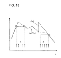
- Fig. 15 is a diagram depicting the top hat processing.
- this image is binarized using a predetermined brightness slice value Th, and an opening processing target area is selected.
- a predetermined brightness slice value Th two-dimensional coordinates (x or y and s) are shown to simplify description.
- the input image is sliced by a predetermined brightness slice value Th, and an area exceeding the slice value is determined as the opening processing range. In other words, if the brightness level of the target line segments is high, it is very unlikely that target line segments exist in an area of which brightness level is low, and it is possible that target line segments exist in an area of which brightness level is high.
- the processing range of the top hat summation section_46 for extracting line segments is set not for the entire image but only for an area of which brightness level of the image is high, so that the time required for top hat summation processing, which normally takes time, is decreased.
- Fig. 13 shows, the operator (or element) B is scanned on the input image A3 (f (x)).
- the operator B has a predetermined length.
- Fig. 13 shows an example of the operator B scanning in three directions.
- AS Fig. 15 shows, when the operator B scans the input image f (x) in the x axis direction, the input image f (x) is divided into a portion where the operator B can enter and a portion where the operator B cannot enter.
- the processing to acquire the envelop of ⁇ B(f) (x) of the portion where the operator B can enter is called "linear opening processing".
- top hat processing is performed on the input image.
- the top hat processing is performed using the following Expression (4). f x - ⁇ B f ⁇ x
- the function of the portion where the operator B cannot enter this is called "top hat" in Fig. 15 is acquired.
- FIG. 14 This opening processing and top hat summation processing will be described using image examples in Fig. 14 .
- the image data when the image B1 is binarized is described using the example of extracting linear components which extend in the x and y directions will be described to simplify description.
- the hatched portion is an area of which brightness level is high.
- the binarized input image is acquired.
- the abscissa is x and the ordinate is y.
- the operator Bx in the x direction is an operator having a three pixel length in the x direction
- operator By in the y direction is an operator having a three pixel length in the y direction.
- the operator Bx is scanned in the x direction of the input image, and the locus in which operator Bx can enter is determined, as described above, then the x axis linear opening image is acquired.
- the pixel value "1" is assigned to the portions where "1" continues for three pixels in the x axis direction of the input image, otherwise pixel value "0" is assigned.
- the x axis top hat image is acquired for each pixel by Expression (4). Compared with the original image B1, this image indicates the contour of the linear components which continue in the x axis direction.
- the operator By is scanned in the y direction of the input image, and the locus in which the operator By can enter is determined as described above, then the y axis linear opening image is acquired.
- pixel value "1" is assigned to the portion where "1" continues for three pixels in the y axis direction of the input image, otherwise pixel value "0" is assigned.
- the y axis top hat image is acquired for each pixel by Expression (4). Compared with the original image B1, this image indicates the linear components which continue in the y axis direction.
- This x axis top hat image and y axis top hat image are added for each pixel, and the top hat summation image is acquired.
- the isolated linear components indicated by black dots in the image B1 are removed, and the continuous linear components of the original image B1 are extracted.
- Fig. 16 is a flow chart depicting the extraction target area selection processing
- Fig. 17 is a diagram depicting the extraction range selection processing in Fig. 16
- Fig. 18 is a diagram depicting the histogram creation processing and mask/marker area selection processing in Fig. 16
- Fig. 19 are diagrams depicting the reconstruction processing in Fig. 16 .
- Fig. 18 shows, in this brightness histogram distribution, the brightness level M1, whose frequency is about half of the highest (entire) frequency, is set as the threshold of the mask area, and the pixels having a brightness level of M1 or more on the histogram are selected as the mask area. Then the brightness level M2, whose frequency is about one quarter of the highest frequency (entire frequency), is set as the threshold of the marker area, and the pixels having a brightness level of M2 or more on the histogram are selected as the marker area. In other words, in the histogram, an area of which the brightness level is relatively high is selected as the mask area, and an area whose brightness level is even higher in the mask area is selected as the marker area.
- the top hat summation-processed image is reconstructed.
- the pixels of the selected mask area and marker area are converted into an image, then the image B3, having the mask areas C1 and C3 and marker area C2, is created.
- the mask area C1 where the marker area C2 exists is reconstructed as the line segment D1 as shown in Fig. 19 .
- the line segment C3 where no marker area exists is removed.
- the contrast ratio level difference between the line segment portion and other portions
- the extracted line segments are either C1 or C3, or only C2, in the case of Fig. 19 , and the extracted line segments differ according to the contrast ratio.
- the marker area and the mask area are determined by the pixel level of an area X whose contrast ratio is high, so the marker area and the mask area are determined, while removing the influence of noise from the peripheral portion where the contrast ratio is low.
- the marker area and mask area are determined by the frequency histogram of the brightness level of the pixels of the image, so even if the line segment pattern of the image is different, the relative marker area and mask area corresponding to the image can be selected.
- This log filter section 47 performs the same processing as log filter processing section 40, i.e. integration is performed and edges enhanced by differentiation.
- the purpose is smoothing the line segment D1 acquired in Fig. 19 , and enhancing the edge, as shown in Fig. 21 .
- Fig. 20 shows, the original image after integration is differentiated twice (two times differentiation).
- the rugged portion D3 around the line segment D1 is smoothed, as shown in Fig. 21 , and the smooth line segment element D2 can be extracted.
- This smooth line segment element is processed by the binarization section 48 and line thinning section 49, and the skeletonized line segment is acquired.
- the above mentioned log filter processing makes it easier to perform binarization and thinning, and the line segment can be easily thinned.
- the operator of the top hat summation section 44 was one with a 1 pixel width by 3 pixels length, but the length and width of the operator can be selected according to the extraction target line segment and the required accuracy, and can be about 20 pixels, for example.
- the shape of the operator is not limited to a rectangle, but may be other shapes, such as an ellipse.
- the number of scanning directions of the operator can be selected according to the direction of the extraction target line segments, the accuracy and the processing time, and four or more is desirable.
- the area selection processing 42 by binarization may be omitted.
- the extraction target selection processing 46 may be omitted if the targets have the same contrast ratio.
- the top hat summation processing was described as a morphology processing, but other methods where the method scans an element or operator over the image in a plurality of directions and extracts linear elements from the extracted image in each direction, may be used.
- the application field is not limited to skin surface, but may be for the image of vessels of a living body, or patterns of a living body, for example.
Abstract
Description
- This application is based upon and claims the benefit of priority from the prior
Japanese Patent Application No. 2006-025690, filed on February 2, 2006 - The present invention relates to an image processing method and an image processor for extracting continuous line segments from a variable density image, and more particularly to an image processing method and an image processor for extracting a linearly connected area from a variable density image, considering the growth direction of the line segments.
- As current demands for advancements in personal authentication technology increase , many personal authentication technologies using image data acquired by capturing the image of a body (test subject) have been proposed. For example, an image of a portion which can identify an individual, such as fingerprints, eye retina, face and blood vessels, is captured and a characteristic part is extracted from the captured image for personal authentication. The portion suitable for such personal authentication is a portion formed of relatively continuous line segments.
- A captured image, on the other hand, has relatively low contrast and includes noise depending on the ambient environment and the image capturing status, so innovation is required for this technology to extract these continuous line segments accurately. For this technology to extract continuous line segments from an image, edge enhancement processing and morphology processing for tracking line segments are effective.
- Conventionally it has been proposed that the captured image is binarized, then line segments are extracted using a morphology function and Gaussian Laplacian filter (see
Japanese Patent Application Laid-Open No. 2004-329825 Fig. 3 )). However it is difficult to detect line segments accurately by applying morphology technology to an image after binarizing since grayscale data acquired from the captured image is not used. - Also as a method of performing morphology processing on grayscale data, it has been proposed to perform open processing and top hat processing, which is one morphology processing on grayscale data for extracting line segments, such as an image of vessels from the retina image of a human eye ("Segmentation of Vessel-Like Pattern using Mathematical Morphology and Curvature Evaluation" (F. Zana, J. C. Klein, IEEE Trans. Image Processing, Vol. 10, pp. 1010 to 1019, July 2001).
- Morphology processing, however, which requires many repeats of simple calculation and is a non-linear processing, has a problem in that grayscale data processing (computation) takes time. For example, if morphology processing is applied to personal authentication processing, the authentication time becomes long.
- Also morphology processing is effective for extracting connected line segments, but if the contrast of the image is low, unconnected line segments are also extracted, and line segment extraction accuracy drops.
- With the foregoing in view, it is desirable to provide an image processing method and an image processor for extracting connected line segments from the grayscale data of an image at high-speed using morphology processing.
- It is further desirable to provide an image processing method and an image processor for extracting connected line segments from the grayscale data of an image using morphology processing even if the image has contrast differences.
- It is also desirable to provide an image processing method and an image processor for extracting connected line segments from the grayscale data of an image using morphology processing without being influenced by the image capturing environment.
- It is also desirable to provide an image processing method and an image processor for extracting connected line segments from the grayscale data of a captured living body image using morphology processing.
- An image processing method for extracting line segment elements from a grayscale captured image, according to the present invention, has a step of binarizing an image according to the captured image and selecting an extraction area of the captured image from the binary image, a step of performing morphology processing by scanning an operator over the selected extracting area in a plurality of directions and extracting linear elements from the extracted image in each direction, and a step of extracting line segment elements from the extracted linear elements.
- Also an image processing method for extracting line segment elements from a grayscale captured image, according to the present invention, has a step of scanning an operator over an image according to the captured image in a plurality of directions and executing morphology processing by extracting linear elements from the extracted images in each direction, a step of extracting an area of which the contrast ratio is relatively high and an area of which contrast ratio is relatively low from an image on which morphology processing was performed, and a step of extracting the linear elements in the area of which contrast ratio is relatively low, connecting to the area of which contrast ratio is relatively high, as the line segment elements.
- Also an image processor for extracting line segment elements from a grayscale captured image has an image capturing device for capturing the image of a test subject, and a line segment extraction device for binarizing an image according to the captured image which is captured by the image capturing device, selecting an extraction area of the captured image, executing morphology processing by scanning an operation over the selected extraction area in a plurality of directions, extracting linear elements from the extracted image in each direction, and extracting line segment elements from the extracted linear elements.
- Also an image processor for extracting line segment elements from a grayscale captured image has an image capturing device for capturing the image of a test subject, and a line segment extraction device for scanning an operator over an image according to the captured image which is captured by the image capturing device in a plurality of directions, executing morphology processing for extracting linear elements from the extracted images in each direction, extracting an area of which contrast ratio is relatively high and an area of which contrast ratio is relatively low from the image on which morphology processing was performed, and extracting the linear elements in the area of which contrast ratio is relatively low, connecting to the area of which contrast ratio is relatively high as the line segment elements.
- It is preferable that the present invention further has a step of binarizing an image according to the captured image and selecting an extraction area of the captured image for which morphology processing is executed.
- It is also preferable that the present invention further has a step of creating an image according to the captured image by subjecting the grayscale captured image to smoothing and edge enhancement processing.
- It is also preferable that the present invention further has a step of subjecting the extracted line segment elements to smoothing and edge enhancement processing, and a step of creating line segment data by binarizing the smoothed and edge enhanced line segment elements.
- Also in the present invention, it is preferable that the step of executing the morphology processing further has a step of scanning the operator in a plurality of directions and creating an open processing image in each direction, a step of creating a top hat processing image in each of the directions from an image according to the captured image and the open processing image in each of the directions, and a step of extracting the linear elements by adding the top hat processing image in each of the directions.
- Also in the present invention, it is preferable that the step of extracting line segment elements further has a step of specifying an area of which contrast of the image is possibly high (e.g. meets/exceeds a threshold), a step of extracting an area of which contrast ratio is relatively high and an area of which contrast ratio is relatively low for the specified area of the morphology-processed image, and extracting linear elements in the area of which contrast ratio is relatively low, connection to the area of which contrast ratio is relatively high as the line segment elements.
- Also in the present invention, it is preferable that the step of extracting the area further has a step of calculating a brightness frequency histogram in the specified area, and a step of extracting the area of which contrast ratio is relatively high and area of which contrast ratio is relatively low from the brightness frequency histogram.
- Also in the present invention, it is preferable that the extraction step further has a step of extracting a mask area of which brightness level is relatively low as an area of which contrast ratio is relatively low and a marker area of which brightness level is relatively high as an area of which contrast ratio is relatively high, from the brightness frequency histogram.
- Also in the present invention, it is preferable that the step of extracting the line segment elements further has a step of extracting a mask area having the marker area as the line segment element.
- According to the present invention, morphology processing is performed on an area where continuous line segments possibly exist by scanning an operator, so line segments can be extracted in a plurality of directions at high-speed. Also by the extraction target area selection processing, an area of which contrast ratio is low, continuing from an area of which contrast ratio is high in the line segment growth direction is also extracted as one line segment, so line segments can be extracted with high accuracy regardless the contrast ratio.
- Reference will now be made, by way of example only, to the accompanying drawings in which:
-
Fig. 1 is a block diagram depicting the image processor according to an embodiment of the present invention; -
Fig. 2 is a block diagram depicting the line segment extraction section inFig. 1 ; -
Fig. 3 shows an example of a captured image inFig. 1 andFig. 2 ; -
Fig. 4 shows an example of an image after log filter processing inFig. 3 ; -
Fig. 5 shows an example of area selection from the image inFig. 4 ; -
Fig. 6 shows an example of an image after the morphology processing inFig. 4 ; -
Fig. 7 shows an example of an image after the extraction target selection processing inFig. 6 ; -
Fig. 8 shows an example of an image after log filter processing inFig. 7 ; -
Fig. 9 shows an example of an image after the binary processing inFig. 8 ; -
Fig. 10 is diagram depicting the log filter processing inFig. 2 ; -
Fig. 11 is a flow chart depicting the area selection processing and top hat summation processing inFig. 2 ; -
Fig. 12 is a diagram depicting the area selection processing inFig. 11 ; -
Fig. 13 is a diagram depicting the opening processing inFig. 11 ; -
Fig. 14 is diagram depicting the area selection processing and top hat summation processing inFig. 11 ; -
Fig. 15 is a diagram depicting the top hat summation processing inFig. 11 ; -
Fig. 16 is a flow chart depicting the extraction area selection processing inFig. 2 ; -
Fig. 17 is a diagram depicting the area specification processing inFig. 16 ; -
Fig. 18 is a diagram depicting the histogram creation and mask area and marker area detection processing inFig. 16 ; -
Fig. 19 area diagrams depicting the reconstruction processing inFig. 16 ; -
Fig. 20 area diagrams depicting the log filter processing inFig. 2 ; and -
Fig. 21 is diagram depicting the line segment extraction operation by the log filter processing inFig. 20 . - Embodiments of the present invention will now be described in the sequence of the image processor, image processing method and other embodiments.
-
Fig. 1 is a block diagram depicting the image processor according to an embodiment of the present invention,Fig. 2 is a block diagram depicting the line segment extraction section inFig. 1 , andFig. 3 toFig. 9 are image processing examples of the line segment extraction section inFig. 2 .Fig. 3 to Fig. 9 are examples of line segment extraction processing of the patterns on the skin surface of the test subject image, but the present invention can also be applied to line segment extraction of images of a living body, such as retina vessels. - As
Fig. 1 shows, the image capturingdevice 2 captures an image of thetest subject 5. The image capturingdevice 2 has alight irradiation section 3 for irradiating light with a desired wavelength to thetest subject 5, and an optical systemimage capturing section 4 for receiving the light from thetest subject 5 and converting it into electric signals (image signals). The optical systemimage capturing section 4 is comprised of an optical mechanism, such as a lens, and an image sensor for converting the received light image into image signals (e.g. CMOS image sensor). - The image sensor of the optical system
image capturing section 4 is 640 pixels by 480 pixels, for example, and outputs the electric signals with a magnitude according to the light receiving amount of each pixel to the linesegment extraction section 1. The linesegment extraction section 1 converts the image signals (analog signals) from the image sensor of the optical systemimage capturing section 4 into grayscale digital signals, and extracts line segments from the converted digital image signals. - The line segment extraction processing of the line
segment extraction section 1 will be described with reference toFig. 2 . The captured image is stored as grayscale digital signals. The logfilter processing section 40 smoothes the grayscale image data, removes noise, and performs differentiation twice, to enhance the edge of the image. For example, if thelog filter processor 40 is executed on grayscale captured image G1 (e.g. captured image of skin surface) inFig. 3 , noise is removed by smoothing (integration), and the edge of the image is enhanced by differentiation, and the image shown inFig. 4 (blurred line segment image) G2 is acquired. - An
area selection section 42 binarizes this image G2 with a predetermined threshold and selects an area for performing the later mentioned top hat summation processing, a kind of morphology processing. For example, if the log filter processed image G2, shown inFig. 4 , is binarized, the area selection image shown inFig. 5 is acquired. InFig. 5 , the black portion is selected as an area for performing top hat summation processing . - In a top
hat summation section 44, continuous linear elements are extracted from the log filter-processed image G2. For this, the tophat summation section 44 performs opening processing 44-1, wherein a predetermined length of pixels (called an element or operator) is scanned in a predetermined direction, and a top envelope image to which the operator can enter in a direction of a higher brightness level is created, and top hat summation processing 44-2 for subtracting the top envelope image from the original image G2 to create the top hat image, and adding the top hat image in a plurality of scanning directions for each pixel. - For example, if top hat summation processing is performed on the image G2 in
Fig. 4 , isolated line segments are removed, and image G4, with only continuous linear components (white portions inFig. 6 ) is acquired, as shown inFig. 6 . In the present embodiment, top hat summation processing is performed only on the above mentioned selected areas (Fig. 5 ), that is the area where continuous line segments possibly exist. - If top hat summation processing, which is a kind of morphology processing, is performed in a plurality of directions on an entire image (300,000 pixels in the case of the above example), processing time becomes long. Since the directions of the line segments are unspecified and many, in order to extract continuous line segments accurately the more scanning directions the better, such as 12 directions (every 30 degrees) of scanning is preferable. In this case, time for extraction processing of continuous line segments becomes long. In order to decrease this extraction processing time, it is effective to perform top hat summation processing on an area where continuous line segments possibly exist, as shown in this embodiment.
- When the processing target is grayscale data, a portion where the contrast ratio is different may exist within a continuous line segment. Therefore in the case when the line segment image after top hat summation processing is performed is binarized and line segments are extracted, the portion where the contrast ratio is low is not extracted as a part of the line segment, even if it is continuous from the portion where the contrast ratio is high.
- In the present embodiment, to detect a continuous line segment having portions where the contrast ratio is different, extraction target area selection processing is performed. An extraction target
area selection section 46 is arranged to extract any portion whose contrast ratio is low, continuing the portion of which contrast ratio is high in the line segment growth direction, as one line segment. - For this, the extraction target
area selection section 46 performs an extraction range selection processing 46-1 for selecting an area of which contrast ratio is relatively high in the image G4 after the tophat summation section 44 has processed the extraction area, a histogram creation processing 46-2 for creating the histogram of the extraction range selected in the extraction range selection processing 46-1, a mask area / marker area selection processing 46-3 for selecting an area of which brightness level is relatively high in the histogram as a mask area and selecting an area of which brightness level is even higher in the mask area as the marker area, and a reconstruction processing 46-4 for reconstructing line segments which continue from the marker area in the growth direction from the line segments in the image G4 in the selected mask area. - When the extraction target selection processing is performed on the line segments in the image G4 in
Fig. 6 , the portions of which contrast ratio is low, connecting to the portion of which contrast ratio of continuous line segments is high, are also reconstructed as the same continuous line segments (white portions inFig. 7 ) as image G5 inFig. 7 shows. According to the present invention, continuous line segments of which contrast ratio is the same can be acquired here by the process performed insection 46. - A Log
filter processing section 47 is supplied with this reconstructed image G5, smoothing and edge enhancement are performed, and the smoothed and edge-enhanced line segment image G6 inFig. 8 is acquired. This line segment image G6 is binarized using a predetermined threshold in abinarization section 48, and the binary line segment image G9 shown inFig. 9 is acquired. And a line segment having a certain width is thinned by theline thinning section 49, and the line segment image with a predetermined width (e.g. 1 pixel) is acquired. - In this way, when continuous line segments are extracted by morphology processing, the range of morphology processing is limited to an area where the continuous line segments possibly exist in the image, therefore the processing time of morphology processing which normally takes time can be decreased.
- Also when the line segments are extracted from the line segment image acquired after morphology processing, an area of which contrast ratio is low is also reconstructed as a continuous line segment if it is continued from an area of which contrast ratio is high, so continuous line segments can be accurately extracted regardless of contrast ratio.
- Now the line segment extraction processing mentioned in
Fig. 2 will be described.Fig. 10 is diagram depicting the logfilter processing section 40 inFig. 2 . - In the description of the log filter processing section below, it is assumed that the input image is f, and the image brightness on the xy coordinates (on the image sensor) is f (x, y). The two-dimensional Gaussian function G (x, y) is defined as the following Expression (1).

- The smoothed image F (x, y) is acquired by the convolution of the Gaussian function G and the input image f using the following Expression (2).

- By partially differentiating this smoothed image F (x, y) twice, the output g (x, y) of log filter is acquired using the following Expression (3).

- In Expression (3), ∇ (nabla) indicates partial differentiation, and in Expression (3), the smoothed image F (x, y) is partially differentiated twice. In other words, in the
log filter processing 40, the image is smoothed by integration, and the edge is enhanced by twice the partial differentiation. - The operation of the log
filter processing section 40 is described with reference toFig. 10. Fig. 10 is model diagram created to simplify description. The x axis and y axis in the three-dimensional coordinates indicate two-dimensional plane coordinates, and the s axis indicates the brightness level. When the log filter processing is performed on the input image A1 (f), a smoothed and edge enhanced three-dimensional image A2 (g) is acquired. This image example is shown inFig. 3 andFig. 4 . - Now the processing performed in the
area selection section 42 and tophat summation section 44 will be described.Fig. 11 shows the processes performed by these sections, i.e. area processing by binarization and top hat summation processing,Fig. 12 is a diagram depicting the area selection processing operation by binarization inFig. 11 ,Fig. 13 is a diagram depicting the opening processing of the top hat summation processing,Fig. 14 are diagrams depicting the top hat summation processing, andFig. 15 is a diagram depicting the top hat processing. - The processing in
Fig. 11 will now be described with reference toFig. 12 to Fig. 15 . - (S10) As described above, the log filter processing is executed on the input image, and a log filter image is acquired.
- (S12) Then this image is binarized using a predetermined brightness slice value Th, and an opening processing target area is selected. In
Fig. 12 , two-dimensional coordinates (x or y and s) are shown to simplify description. The input image is sliced by a predetermined brightness slice value Th, and an area exceeding the slice value is determined as the opening processing range. In other words, if the brightness level of the target line segments is high, it is very unlikely that target line segments exist in an area of which brightness level is low, and it is possible that target line segments exist in an area of which brightness level is high. Therefore the processing range of the top hat summation section_46 for extracting line segments is set not for the entire image but only for an area of which brightness level of the image is high, so that the time required for top hat summation processing, which normally takes time, is decreased. - (S14) In the specified opening area (black portion in
Fig. 5 ), the opening processing is performed on the image after log filter processing is performed. The opening processing is already known, but will be briefly described with reference to the model diagrams inFig. 13 andFig. 15 . - As
Fig. 13 shows, the operator (or element) B is scanned on the input image A3 (f (x)). The operator B has a predetermined length.Fig. 13 shows an example of the operator B scanning in three directions. ASFig. 15 shows, when the operator B scans the input image f (x) in the x axis direction, the input image f (x) is divided into a portion where the operator B can enter and a portion where the operator B cannot enter. The processing to acquire the envelop of γB(f) (x) of the portion where the operator B can enter is called "linear opening processing". - (S16) Using this linear-opened image, top hat processing is performed on the input image. The top hat processing is performed using the following Expression (4).

Fig. 15 is acquired. - (S18) The image after top hat processing acquired by scanning the operator in each direction is added for each pixel.
- This opening processing and top hat summation processing will be described using image examples in
Fig. 14 . InFig. 14 , the image data when the image B1 is binarized is described using the example of extracting linear components which extend in the x and y directions will be described to simplify description. In the image B1, the hatched portion is an area of which brightness level is high. By binarizing this image, the binarized input image is acquired. In this description, it is assumed that the abscissa is x and the ordinate is y. It is also assumed that the operator Bx in the x direction is an operator having a three pixel length in the x direction, and operator By in the y direction is an operator having a three pixel length in the y direction. - First the operator Bx is scanned in the x direction of the input image, and the locus in which operator Bx can enter is determined, as described above, then the x axis linear opening image is acquired. In other words, the pixel value "1" is assigned to the portions where "1" continues for three pixels in the x axis direction of the input image, otherwise pixel value "0" is assigned.
- Using this x axis linear opening image and input image, the x axis top hat image is acquired for each pixel by Expression (4). Compared with the original image B1, this image indicates the contour of the linear components which continue in the x axis direction.
- In the same way, the operator By is scanned in the y direction of the input image, and the locus in which the operator By can enter is determined as described above, then the y axis linear opening image is acquired. In other words, pixel value "1" is assigned to the portion where "1" continues for three pixels in the y axis direction of the input image, otherwise pixel value "0" is assigned.
- Using this y axis linear opening image and input image, the y axis top hat image is acquired for each pixel by Expression (4). Compared with the original image B1, this image indicates the linear components which continue in the y axis direction.
- This x axis top hat image and y axis top hat image are added for each pixel, and the top hat summation image is acquired. Compared with the original image B1, the isolated linear components indicated by black dots in the image B1 are removed, and the continuous linear components of the original image B1 are extracted.
- Now the extraction target
area selection section 46 will be described with reference toFig. 16 to Fig. 19 .Fig. 16 is a flow chart depicting the extraction target area selection processing,Fig. 17 is a diagram depicting the extraction range selection processing inFig. 16 ,Fig. 18 is a diagram depicting the histogram creation processing and mask/marker area selection processing inFig. 16 , andFig. 19 are diagrams depicting the reconstruction processing inFig. 16 . - Now the extraction target area selection processing in
Fig. 16 will be described with reference toFig. 17 to Fig. 19 . - (S20) An area of which contrast ratio is relatively high out of the image G4 after the top hat summation processing is performed is selected as the extraction range X. As
Fig. 17 shows, the center portion of the image Y tends to have a higher contrast ratio than the peripheral portion. This is related to the image capturing conditions. In other words, depending on the performance of the optical system, the light illuminating the test subject, and the ambient light conditions of the image capturing device, an image tends to become blurred in the peripheral portion. Therefore in the extraction range selection processing 46-1, the area X, including the center portion of the image Y, excluding the peripheral portion, is selected as the target area, as shown inFig. 17 . - (S22) Then the histogram of the extraction range X selected in the extraction range selection processing 46-1 is calculated. As
Fig. 18 shows, the abscissa is the brightness level and the ordinate is the frequency of the pixels, and the number of pixels at each brightness level is calculated as the brightness histogram. - (S24) As
Fig. 18 shows, in this brightness histogram distribution, the brightness level M1, whose frequency is about half of the highest (entire) frequency, is set as the threshold of the mask area, and the pixels having a brightness level of M1 or more on the histogram are selected as the mask area. Then the brightness level M2, whose frequency is about one quarter of the highest frequency (entire frequency), is set as the threshold of the marker area, and the pixels having a brightness level of M2 or more on the histogram are selected as the marker area. In other words, in the histogram, an area of which the brightness level is relatively high is selected as the mask area, and an area whose brightness level is even higher in the mask area is selected as the marker area. - (S26) Using this mask area and marker area, the top hat summation-processed image is reconstructed. In other words, as
Fig. 19 shows, the pixels of the selected mask area and marker area are converted into an image, then the image B3, having the mask areas C1 and C3 and marker area C2, is created. For the reconstruction, the mask area C1, where the marker area C2 exists, is reconstructed as the line segment D1 as shown inFig. 19 . Here the line segment C3 where no marker area exists, is removed. - In the same way, even if the contrast ratio (level difference between the line segment portion and other portions) of an area is low, it is extracted as one line segment if the area is connected to the line segment having elements whose contrast ratio is high. If this
processing 46 is not executed, the extracted line segments are either C1 or C3, or only C2, in the case ofFig. 19 , and the extracted line segments differ according to the contrast ratio. - Also the marker area and the mask area are determined by the pixel level of an area X whose contrast ratio is high, so the marker area and the mask area are determined, while removing the influence of noise from the peripheral portion where the contrast ratio is low.
- Also the marker area and mask area are determined by the frequency histogram of the brightness level of the pixels of the image, so even if the line segment pattern of the image is different, the relative marker area and mask area corresponding to the image can be selected.
- Now the
leg filter section 47 will be described with reference toFig. 20 to Fig. 21 . Thislog filter section 47 performs the same processing as logfilter processing section 40, i.e. integration is performed and edges enhanced by differentiation. However in thelog filter section 47 in the subsequent step of the line segment extraction, the purpose is smoothing the line segment D1 acquired inFig. 19 , and enhancing the edge, as shown inFig. 21 . In other words, asFig. 20 shows, the original image after integration is differentiated twice (two times differentiation). By this, the rugged portion D3 around the line segment D1 is smoothed, as shown inFig. 21 , and the smooth line segment element D2 can be extracted. - This smooth line segment element is processed by the
binarization section 48 andline thinning section 49, and the skeletonized line segment is acquired. The above mentioned log filter processing makes it easier to perform binarization and thinning, and the line segment can be easily thinned. - In the above embodiments, the operator of the top
hat summation section 44 was one with a 1 pixel width by 3 pixels length, but the length and width of the operator can be selected according to the extraction target line segment and the required accuracy, and can be about 20 pixels, for example. The shape of the operator is not limited to a rectangle, but may be other shapes, such as an ellipse. - The number of scanning directions of the operator can be selected according to the direction of the extraction target line segments, the accuracy and the processing time, and four or more is desirable. When the number of scanning directions is low and a longer processing time can be taken, the
area selection processing 42 by binarization may be omitted. In the same way, the extractiontarget selection processing 46 may be omitted if the targets have the same contrast ratio. - The top hat summation processing was described as a morphology processing, but other methods where the method scans an element or operator over the image in a plurality of directions and extracts linear elements from the extracted image in each direction, may be used. The application field is not limited to skin surface, but may be for the image of vessels of a living body, or patterns of a living body, for example.
- The present invention was described by the embodiments, but the present invention can be modified in various ways within the scope of the essential character of the present invention, and these shall not be excluded from the scope of the present invention.
- Since morphology processing is performed on an area where continuous line segments possibly exist by scanning an operator, line segment elements can be extracted in a plurality of directions at high-speed. Also an area of which contrast ratio is low, continuing from an area of which contrast ratio is high in the line segment growth direction is also extracted as one line segment, so line segments can be extracted with high accuracy, regardless of contrast ratio. Therefore continuous line segments can be accurately extracted from a blurred image.
Claims (18)
- An image processing method for extracting line segment elements from a grayscale captured image, comprising:a step of executing morphology processing (44) by scanning an operator over an image according to said captured image in a plurality of directions and extracting linear elements from the extracted images in each direction; and characterized by:a step of extracting an area in which the contrast ratio is relatively high and an area in which the contrast ratio is relatively low from the image on which said morphology processing is performed; anda step of extracting the linear elements in said area in which the contrast ratio is relatively low, connecting to said area in which the contrast ratio is relatively high, as the line segment elements.
- The image processing method according to Claim 1, further comprising a step of binarizing an image according to said captured image, and selecting an extraction area of said captured image for which said morphology processing is executed.
- The image processing method according to Claim 1, wherein said step of extracting line segment elements further comprises:a step of specifying an area in which the contrast ratio of the image according to said captured image is possibly high, or in other words an area where continuous line segments possibly exist;a step of extracting an area in which the contrast ratio is relatively high and an area in which the contrast ratio is relatively low for said specified area of said morphology-processed image; anda step of extracting linear elements in said area in which the contrast ratio is relatively low, connecting to said area in which the contrast ratio is relatively high, as the line segment elements.
- The image processing method according to Claim 3, wherein said step of extracting the area further comprises:a step of calculating a brightness frequency histogram in said specified area; anda step of extracting said area in which the contrast ratio is relatively high and area in which the contrast ratio is relatively low from said frequency histogram.
- The image processing method according to Claim 4, wherein said extraction step further comprises a step of extracting a mask area in which the brightness level is relatively low as an area in which the contrast ratio is relatively low, and a marker area in which the brightness level is relatively high as an area in which the contrast ratio is relatively high, from said frequency histogram.
- The image processing method according to Claim 5, wherein said step of extracting said line segment elements further comprises a step of extracting said mask area having said marker area as said line segment element.
- The image processing method according to Claim 1, further comprising a step of creating an image according to said captured image by subjecting said grayscale captured image to smoothing and edge enhancement processing.
- The image processing method according to Claim 1, further comprising:a step of subjecting said extracted line segment elements to smoothing and edge enhancement processing; anda step of creating line segment data by binarizing said smoothed and edge-enhanced line segment elements.
- The image processing method according to Claim 1, wherein said step of executing morphology processing comprises:a step of scanning said operator in a plurality of directions and creating an open processing image in each direction;a step of creating a top hat processing image in each of said directions from an image according to said captured image and the open processing image in each of said directions; anda step of extracting said linear elements by adding the top hat processing image in each of said directions.
- An image processor for extracting line segment elements from a grayscale captured image, comprising:an image capturing device (2) for capturing the image of a test subject (5); anda line segment extraction device (1) for executing morphology processing for extracting linear elements from the extracted images in each direction by scanning an operator over an image according to said captured image which is captured by said image capturing device in a plurality of directions;characterised in that the line segment extraction device (1) extracts an area in which the contrast ratio is relatively high and an area in which the contrast ratio is relatively low from the image on which said morphology processing is performed, and extracts the linear elements in said area in which the contrast ratio is relatively low, connecting to said area of in which the contrast ratio is relatively high, as the line segment elements.
- The image processor according to Claim 10, wherein said line segment extraction device (1) binarizes an image according to said captured image and selects an extraction area of said captured image for which said morphology processing is executed.
- The image processor according to Claim 10, wherein said line segment extraction device (1) extracts an area in which the contrast ratio is relatively high and an area in which the contrast ratio is relatively low for an area in which the contrast ratio of said captured image is possibly high out of said morphology processed image, and extracts linear elements in said area in which the contrast ratio is relatively low, connecting to said area in which the contrast ratio is relatively high, as line segment elements.
- The image processor according to Claim 12, wherein said line segment extraction device (1) calculates a brightness frequency histogram in said specified area, and extracts said area in which the contrast ratio is relatively high and area in which the contrast ratio is relatively low from said brightness frequency histogram.
- The image processor according to Claim 13, wherein said line segment extraction device (1) extracts a mask area in which the brightness level is relatively low as an area in which the contrast ratio is relatively low, and a marker area in which the brightness level is relatively high as an area in which the contrast ratio is relatively high, from said frequency histogram.
- The image processor according to Claim 14, wherein said line segment extraction device (1) extracts said mask area having said marker area as said line segment elements.
- The image processor according to Claim 10, wherein said line segment extraction device (1) creates an image according to said captured image by subjecting said grayscale captured image to smoothing and edge enhancement processing.
- The image processor according to Claim 10, wherein said line segment extraction device (1) subjects said extracted line segment elements to smoothing and edge enhancement processing, and creates line segment data by binarizing said smoothed and edge-enhanced line segment elements.
- The image processor according to Claim 10, wherein said line segment extraction device (1) scans said operator in a plurality of directions and creates an open processing image in each direction, and creates a top hat processing image in each of said directions from an image according to said captured image and the open processing image in each of said directions, and extracts said linear elements by adding the top hat processing image in each of said directions.
Applications Claiming Priority (2)
| Application Number | Priority Date | Filing Date | Title |
|---|---|---|---|
| JP2006025690A JP2007207009A (en) | 2006-02-02 | 2006-02-02 | Image processing method and image processor |
| EP06254493A EP1816588B1 (en) | 2006-02-02 | 2006-08-29 | Image processing method and image processor |
Related Parent Applications (1)
| Application Number | Title | Priority Date | Filing Date |
|---|---|---|---|
| EP06254493A Division EP1816588B1 (en) | 2006-02-02 | 2006-08-29 | Image processing method and image processor |
Publications (2)
| Publication Number | Publication Date |
|---|---|
| EP1918852A1 true EP1918852A1 (en) | 2008-05-07 |
| EP1918852B1 EP1918852B1 (en) | 2009-12-09 |
Family
ID=37950194
Family Applications (2)
| Application Number | Title | Priority Date | Filing Date |
|---|---|---|---|
| EP08101233A Active EP1918852B1 (en) | 2006-02-02 | 2006-08-29 | Image processing method and image processor |
| EP06254493A Active EP1816588B1 (en) | 2006-02-02 | 2006-08-29 | Image processing method and image processor |
Family Applications After (1)
| Application Number | Title | Priority Date | Filing Date |
|---|---|---|---|
| EP06254493A Active EP1816588B1 (en) | 2006-02-02 | 2006-08-29 | Image processing method and image processor |
Country Status (6)
| Country | Link |
|---|---|
| US (1) | US8606012B2 (en) |
| EP (2) | EP1918852B1 (en) |
| JP (1) | JP2007207009A (en) |
| KR (2) | KR100908856B1 (en) |
| CN (1) | CN101013469B (en) |
| DE (2) | DE602006015033D1 (en) |
Families Citing this family (22)
| Publication number | Priority date | Publication date | Assignee | Title |
|---|---|---|---|---|
| KR100912128B1 (en) * | 2006-12-08 | 2009-08-13 | 한국전자통신연구원 | Apparatus and method for detecting horizon in a sea image |
| KR100886611B1 (en) * | 2007-08-14 | 2009-03-05 | 한국전자통신연구원 | Method and apparatus for detecting line segment by incremental pixel extension in an image |
| WO2009034688A1 (en) * | 2007-09-10 | 2009-03-19 | Nikon Corporation | Image processing method and program |
| KR100960003B1 (en) * | 2007-11-30 | 2010-05-28 | 주식회사 에이스테크놀로지 | Apparatus for adjusting an azimuth angle in an antenna |
| US8737703B2 (en) * | 2008-01-16 | 2014-05-27 | The Charles Stark Draper Laboratory, Inc. | Systems and methods for detecting retinal abnormalities |
| US8718363B2 (en) * | 2008-01-16 | 2014-05-06 | The Charles Stark Draper Laboratory, Inc. | Systems and methods for analyzing image data using adaptive neighborhooding |
| US8351720B2 (en) * | 2008-04-24 | 2013-01-08 | Hewlett-Packard Development Company, L.P. | Method and system providing edge enhanced image binarization |
| CN101625722B (en) * | 2009-08-11 | 2012-01-11 | 中国农业大学 | Classification method of carrier recognition image |
| JP5198420B2 (en) * | 2009-12-18 | 2013-05-15 | 株式会社日立ハイテクノロジーズ | Image processing apparatus, measurement / inspection system, and program |
| TWI419013B (en) * | 2010-07-12 | 2013-12-11 | Chip Goal Electronics Corp | Locus smoothing method |
| CN102542557A (en) * | 2010-12-30 | 2012-07-04 | 方正国际软件(北京)有限公司 | Method and system for extracting lines from image |
| US8824792B2 (en) * | 2012-07-25 | 2014-09-02 | Ib Korea Ltd. | Image element brightness adjustment |
| CN103198321B (en) * | 2013-03-27 | 2016-06-15 | 中国科学院苏州生物医学工程技术研究所 | Retinal images treatment process and device |
| TWI492193B (en) * | 2013-06-14 | 2015-07-11 | Utechzone Co Ltd | Method for triggering signal and electronic apparatus for vehicle |
| CN103679176A (en) * | 2013-12-30 | 2014-03-26 | 北京航空航天大学 | Linear feature extraction method utilizing multi-scale multi-constructing-element top-hat transformation |
| CN104091180B (en) * | 2014-07-14 | 2017-07-28 | 南京原觉信息科技有限公司 | The recognition methods of trees and building in outdoor scene image |
| US10846852B2 (en) * | 2016-12-23 | 2020-11-24 | Bio-Rad Laboratories, Inc. | Reduction of background signal in blot images |
| CN107144572A (en) * | 2017-05-26 | 2017-09-08 | 太原科技大学 | Crack automatic recognition and detection method in gray level image |
| CN109724364B (en) * | 2018-11-13 | 2020-11-20 | 徐州云创物业服务有限公司 | Deposited article capacity analysis platform |
| CN112200053B (en) * | 2020-09-30 | 2023-08-22 | 西安工业大学 | Form identification method integrating local features |
| CN115909050B (en) * | 2022-10-26 | 2023-06-23 | 中国电子科技集团公司第五十四研究所 | Remote sensing image airport extraction method combining line segment direction and morphological difference |
| CN116385438B (en) * | 2023-06-05 | 2023-08-11 | 济南科汛智能科技有限公司 | Nuclear magnetic resonance tumor region extraction method |
Citations (4)
| Publication number | Priority date | Publication date | Assignee | Title |
|---|---|---|---|---|
| US5878158A (en) * | 1995-05-10 | 1999-03-02 | Ferris; Stephen G. | Ridge-valley minutia associator for fingerprints |
| WO1999051138A2 (en) * | 1998-04-02 | 1999-10-14 | Precise Biometrics Ab | Fingerprint identification/verification system |
| US6047090A (en) * | 1996-07-31 | 2000-04-04 | U.S. Philips Corporation | Method and device for automatic segmentation of a digital image using a plurality of morphological opening operation |
| US20040116808A1 (en) * | 2002-11-06 | 2004-06-17 | Terry Fritz | Ultrasonic blood vessel measurement apparatus and method |
Family Cites Families (17)
| Publication number | Priority date | Publication date | Assignee | Title |
|---|---|---|---|---|
| JPH06314339A (en) * | 1993-04-27 | 1994-11-08 | Honda Motor Co Ltd | Image rectilinear component extracting device |
| JPH09326026A (en) * | 1996-06-07 | 1997-12-16 | Advantest Corp | Image processing method and its device |
| JPH10233693A (en) | 1996-12-16 | 1998-09-02 | Canon Inc | Image processing method and device and storage medium |
| JP3067704B2 (en) | 1997-08-11 | 2000-07-24 | 日本電気株式会社 | Edge detection method and apparatus |
| JP3705938B2 (en) | 1997-10-20 | 2005-10-12 | 富士通株式会社 | Fingerprint registration device, fingerprint verification device, and fingerprint verification method |
| US6407090B1 (en) * | 1999-06-23 | 2002-06-18 | Zinc Therapeutics Canada, Inc. | Zinc ionophores as anti-apoptotic agents |
| JP2002092616A (en) | 2000-09-20 | 2002-03-29 | Hitachi Ltd | Individual authentication device |
| JP2002269539A (en) | 2000-12-01 | 2002-09-20 | Shigehiro Masui | Image processor, image processing method, and computer- readable storage medium with image processing program stored therein, and diagnosis support system using them |
| JP2003044860A (en) * | 2001-08-01 | 2003-02-14 | Nippon Hoso Kyokai <Nhk> | Device for tracing video object |
| JP2004045356A (en) * | 2002-05-20 | 2004-02-12 | Jfe Steel Kk | Surface defect detection method |
| JP3946590B2 (en) * | 2002-07-16 | 2007-07-18 | 富士通株式会社 | Image processing method, image processing program, and image processing apparatus |
| DE60302191T2 (en) * | 2002-08-27 | 2006-07-27 | Oce Print Logic Technologies S.A. | Determination of the skew of document images |
| CN1238809C (en) * | 2002-09-04 | 2006-01-25 | 长春鸿达光电子与生物统计识别技术有限公司 | Fingerprint identification method as well as fingerprint controlling method and system |
| JP4389489B2 (en) * | 2003-05-06 | 2009-12-24 | ソニー株式会社 | Image processing method and image processing apparatus |
| JP2005127989A (en) * | 2003-10-03 | 2005-05-19 | Olympus Corp | Flaw detector and flaw detecting program |
| JP4651379B2 (en) * | 2003-12-26 | 2011-03-16 | 富士フイルム株式会社 | Ultrasonic image processing apparatus, ultrasonic image processing method, and ultrasonic image processing program |
| JP2005275500A (en) | 2004-03-23 | 2005-10-06 | Zenrin Co Ltd | Vanishing point decision method |
-
2006
- 2006-02-02 JP JP2006025690A patent/JP2007207009A/en active Pending
- 2006-08-25 US US11/509,844 patent/US8606012B2/en active Active
- 2006-08-29 EP EP08101233A patent/EP1918852B1/en active Active
- 2006-08-29 DE DE602006015033T patent/DE602006015033D1/en active Active
- 2006-08-29 DE DE602006011025T patent/DE602006011025D1/en active Active
- 2006-08-29 EP EP06254493A patent/EP1816588B1/en active Active
- 2006-09-21 CN CN2006101398666A patent/CN101013469B/en active Active
- 2006-09-21 KR KR1020060091563A patent/KR100908856B1/en active IP Right Grant
-
2009
- 2009-03-26 KR KR1020090026086A patent/KR100944171B1/en active IP Right Grant
Patent Citations (4)
| Publication number | Priority date | Publication date | Assignee | Title |
|---|---|---|---|---|
| US5878158A (en) * | 1995-05-10 | 1999-03-02 | Ferris; Stephen G. | Ridge-valley minutia associator for fingerprints |
| US6047090A (en) * | 1996-07-31 | 2000-04-04 | U.S. Philips Corporation | Method and device for automatic segmentation of a digital image using a plurality of morphological opening operation |
| WO1999051138A2 (en) * | 1998-04-02 | 1999-10-14 | Precise Biometrics Ab | Fingerprint identification/verification system |
| US20040116808A1 (en) * | 2002-11-06 | 2004-06-17 | Terry Fritz | Ultrasonic blood vessel measurement apparatus and method |
Non-Patent Citations (4)
| Title |
|---|
| BRETT D THACKRAY; ALAN VC NELSON: "Semi-Automatic Segmentation of Vascular Network Images Using a Rotating Structural Element (ROSE) With Mathematical Morphology and Dual Feature Thresholding", IEEE TRANSACTIONS ON MEDICAL IMAGING, no. 3, September 1993 (1993-09-01) |
| EIHO S ET AL: "Detection of coronary artery tree using morphological operator", COMPUTERS IN CARDIOLOGY 1997 LUND, SWEDEN 7-10 SEPT. 1997, NEW YORK, NY, USA,IEEE, US, 7 September 1997 (1997-09-07), pages 525 - 528, XP010264572, ISBN: 0-7803-4445-6 * |
| KIRBAS C ET AL: "Vessel extraction techniques and algorithms :a survey", BIOINFORMATICS AND BIOENGINEERING, 2003. PROCEEDINGS. THIRD IEEE SYMPOSIUM ON 10-12 MARCH 2003, PISCATAWAY, NJ, USA,IEEE, 10 March 2003 (2003-03-10), pages 238 - 245, XP010637101, ISBN: 0-7695-1907-5 * |
| THACKRAY B D ET AL: "SEMI-AUTOMATIC SEGMENTATION OF VASCULAR NETWORK IMAGES USING A ROTATING STRUCTURING ELEMENT (ROSE) WITH MATHEMATICAL MORPHOLOGY AND DUAL FEATURE THRESHOLDING", IEEE TRANSACTIONS ON MEDICAL IMAGING, IEEE SERVICE CENTER, PISCATAWAY, NJ, US, vol. 12, no. 3, 1 September 1993 (1993-09-01), pages 385 - 392, XP000412315, ISSN: 0278-0062 * |
Also Published As
| Publication number | Publication date |
|---|---|
| CN101013469B (en) | 2011-01-12 |
| EP1816588B1 (en) | 2010-06-23 |
| US20070177825A1 (en) | 2007-08-02 |
| CN101013469A (en) | 2007-08-08 |
| JP2007207009A (en) | 2007-08-16 |
| KR100908856B1 (en) | 2009-07-21 |
| EP1816588A1 (en) | 2007-08-08 |
| DE602006015033D1 (en) | 2010-08-05 |
| KR20070079552A (en) | 2007-08-07 |
| DE602006011025D1 (en) | 2010-01-21 |
| KR100944171B1 (en) | 2010-02-24 |
| KR20090040412A (en) | 2009-04-24 |
| US8606012B2 (en) | 2013-12-10 |
| EP1918852B1 (en) | 2009-12-09 |
Similar Documents
| Publication | Publication Date | Title |
|---|---|---|
| EP1816588B1 (en) | Image processing method and image processor | |
| Nedzved et al. | Morphological segmentation of histology cell images | |
| Esmaeili et al. | Automatic detection of exudates and optic disk in retinal images using curvelet transform | |
| US9454817B2 (en) | Relating to image processing | |
| Wang et al. | Building palm vein capturing system for extraction | |
| Chaudhari et al. | A study and review on fingerprint image enhancement and minutiae extraction | |
| JP2005056282A (en) | Image processing method and apparatus and program | |
| Ruslau et al. | Edge detection of digital image with different edge types | |
| JP4020202B2 (en) | Striped pattern extraction system and striped pattern extraction method | |
| JP5087151B2 (en) | Image processing method, image processing apparatus, and image processing program | |
| Perera et al. | A novel image enhancement method for palm vein images | |
| Kabacinski et al. | Human Vein Pattern Correlation-A Comparison of Segmentation Methods. | |
| Chandra et al. | Retinal based image enhancement using contourlet transform | |
| KR101750897B1 (en) | A Biometric Method using Thumb feature | |
| CN113221909B (en) | Image processing method, image processing apparatus, and computer-readable storage medium | |
| Vlachos et al. | A finger vein pattern extraction algorithm based on filtering in multiple directions | |
| Gayathri et al. | Retinal Blood Vessels Extraction Based on Curvelet Transform and by Combining Bothat and Tophat Morphology | |
| Hamid et al. | Fingerprint Image Enhancement Using Median Sigmoid Filter | |
| Priyadarshini et al. | Analogizing the thinning algorithm on fingerprint in minutiae extraction | |
| Ardizzone et al. | Optic disc positioning and blood vessels extraction on eye fundus | |
| Vlachos et al. | Vessel network extraction in retinal images using iterative line tracking | |
| Qahwaji | Detecting edges in noisy face database images | |
| Goswami et al. | Spatial Filtering and Morphological Operation as Pre-Processing Steps in Fingerprint Feature Extraction | |
| Devi | DETECTION AND SEGMENTATION OF DRUSEN IN THE HUMAN EYE IMAGE | |
| Nabil et al. | Retinal vessel extraction by MF-FDOG, Morphological Mathematic and ISODATA |
Legal Events
| Date | Code | Title | Description |
|---|---|---|---|
| PUAI | Public reference made under article 153(3) epc to a published international application that has entered the european phase |
Free format text: ORIGINAL CODE: 0009012 |
|
| AC | Divisional application: reference to earlier application |
Ref document number: 1816588 Country of ref document: EP Kind code of ref document: P |
|
| AK | Designated contracting states |
Kind code of ref document: A1 Designated state(s): AT BE BG CH CY CZ DE DK EE ES FI FR GB GR HU IE IS IT LI LT LU LV MC NL PL PT RO SE SI SK TR |
|
| AX | Request for extension of the european patent |
Extension state: AL BA MK RS |
|
| 17P | Request for examination filed |
Effective date: 20081105 |
|
| AKX | Designation fees paid |
Designated state(s): DE FR GB |
|
| GRAP | Despatch of communication of intention to grant a patent |
Free format text: ORIGINAL CODE: EPIDOSNIGR1 |
|
| GRAS | Grant fee paid |
Free format text: ORIGINAL CODE: EPIDOSNIGR3 |
|
| GRAA | (expected) grant |
Free format text: ORIGINAL CODE: 0009210 |
|
| AC | Divisional application: reference to earlier application |
Ref document number: 1816588 Country of ref document: EP Kind code of ref document: P |
|
| AK | Designated contracting states |
Kind code of ref document: B1 Designated state(s): DE FR GB |
|
| REG | Reference to a national code |
Ref country code: GB Ref legal event code: FG4D |
|
| REF | Corresponds to: |
Ref document number: 602006011025 Country of ref document: DE Date of ref document: 20100121 Kind code of ref document: P |
|
| PLBE | No opposition filed within time limit |
Free format text: ORIGINAL CODE: 0009261 |
|
| STAA | Information on the status of an ep patent application or granted ep patent |
Free format text: STATUS: NO OPPOSITION FILED WITHIN TIME LIMIT |
|
| 26N | No opposition filed |
Effective date: 20100910 |
|
| REG | Reference to a national code |
Ref country code: FR Ref legal event code: PLFP Year of fee payment: 11 |
|
| REG | Reference to a national code |
Ref country code: FR Ref legal event code: PLFP Year of fee payment: 12 |
|
| REG | Reference to a national code |
Ref country code: FR Ref legal event code: PLFP Year of fee payment: 13 |
|
| REG | Reference to a national code |
Ref country code: DE Ref legal event code: R082 Ref document number: 602006011025 Country of ref document: DE Representative=s name: REICHERT & LINDNER PARTNERSCHAFT PATENTANWAELT, DE Ref country code: DE Ref legal event code: R081 Ref document number: 602006011025 Country of ref document: DE Owner name: FUJITSU FRONTECH LTD., INAGI, JP Free format text: FORMER OWNERS: FUJITSU LIMITED, KAWASAKI-SHI, KANAGAWA, JP; FUJITSU FRONTECH LTD., INAGI, TOKIO/TOKYO, JP |
|
| REG | Reference to a national code |
Ref country code: GB Ref legal event code: 732E Free format text: REGISTERED BETWEEN 20190429 AND 20190502 |
|
| REG | Reference to a national code |
Ref country code: DE Ref legal event code: R079 Ref document number: 602006011025 Country of ref document: DE Free format text: PREVIOUS MAIN CLASS: G06K0009000000 Ipc: G06V0010000000 |
|
| PGFP | Annual fee paid to national office [announced via postgrant information from national office to epo] |
Ref country code: GB Payment date: 20230706 Year of fee payment: 18 |
|
| PGFP | Annual fee paid to national office [announced via postgrant information from national office to epo] |
Ref country code: FR Payment date: 20230703 Year of fee payment: 18 Ref country code: DE Payment date: 20230705 Year of fee payment: 18 |