EP1513116A2 - Gaming machine - Google Patents
Gaming machine Download PDFInfo
- Publication number
- EP1513116A2 EP1513116A2 EP04021383A EP04021383A EP1513116A2 EP 1513116 A2 EP1513116 A2 EP 1513116A2 EP 04021383 A EP04021383 A EP 04021383A EP 04021383 A EP04021383 A EP 04021383A EP 1513116 A2 EP1513116 A2 EP 1513116A2
- Authority
- EP
- European Patent Office
- Prior art keywords
- lottery
- bingo
- game
- indicia
- boxes
- Prior art date
- Legal status (The legal status is an assumption and is not a legal conclusion. Google has not performed a legal analysis and makes no representation as to the accuracy of the status listed.)
- Granted
Links
Images


Classifications
-
- G—PHYSICS
- G07—CHECKING-DEVICES
- G07F—COIN-FREED OR LIKE APPARATUS
- G07F17/00—Coin-freed apparatus for hiring articles; Coin-freed facilities or services
- G07F17/32—Coin-freed apparatus for hiring articles; Coin-freed facilities or services for games, toys, sports, or amusements
- G07F17/3202—Hardware aspects of a gaming system, e.g. components, construction, architecture thereof
- G07F17/3204—Player-machine interfaces
- G07F17/3211—Display means
- G07F17/3213—Details of moving display elements, e.g. spinning reels, tumbling members
-
- G—PHYSICS
- G07—CHECKING-DEVICES
- G07F—COIN-FREED OR LIKE APPARATUS
- G07F17/00—Coin-freed apparatus for hiring articles; Coin-freed facilities or services
- G07F17/32—Coin-freed apparatus for hiring articles; Coin-freed facilities or services for games, toys, sports, or amusements
-
- G—PHYSICS
- G07—CHECKING-DEVICES
- G07F—COIN-FREED OR LIKE APPARATUS
- G07F17/00—Coin-freed apparatus for hiring articles; Coin-freed facilities or services
- G07F17/32—Coin-freed apparatus for hiring articles; Coin-freed facilities or services for games, toys, sports, or amusements
- G07F17/3202—Hardware aspects of a gaming system, e.g. components, construction, architecture thereof
- G07F17/3204—Player-machine interfaces
- G07F17/3209—Input means, e.g. buttons, touch screen
Definitions
- This invention relates to a gaming machine including a display unit for displaying information concerning game play and a lottery unit for drawing indicia, wherein the game result is determined based on the lottery result of the lottery unit.
- a bingo game has been played wherein using a bingo card having a matrix of boxes assigned various pieces of indicia, a player bores a hole in the box to which the indicia drawn as a win corresponds and the earliest player who completes boring holes in a vertical, horizontal, or diagonal row wins the game.
- a paper bingo card is used for the bingo game, but various electronically controlled gaming machines simulating the bingo game are developed. With such a gaming machine, a bingo card is displayed on a display as a matrix of bingo boxes and when the indicia drawn as a win exists on the bingo card, the corresponding bingo box is activated and is displayed so that it can be distinguished from other bingo boxes.
- a gaming machine for enabling the player to move a bingo box of a bingo card under a predetermined constraint to enhance the game amusement of the bingo game is proposed. (For example, refer to JP-A-2001-161888.)
- the gaming machine does not include a display unit for indicating which bingo box is to be next activated to complete one row and thus the player must see the whole matrix of the bingo card carefully and if one row is completed by activating one additional bingo box, it is feared that the play may be unaware of it.
- a gaming machine including a display unit (for example, main control circuit 500A, display controller 600A, and display 370A later described with reference to FIG. 11, means for executing step S209 in FIG. 17, and the like) for displaying a game card (for example, a bingo card) formed as a matrix of game boxes (for example, a matrix of bingo boxes); an indicia display data storage unit (for example, ROM 508A later described with reference to FIG.
- a display unit for example, main control circuit 500A, display controller 600A, and display 370A later described with reference to FIG. 11, means for executing step S209 in FIG. 17, and the like
- a game card for example, a bingo card
- an indicia display data storage unit for example, ROM 508A later described with reference to FIG.
- a game card indicia determination unit for example, main control circuit 500A later described with reference to FIG. 11, means for executing step S209 in FIG.
- a lottery unit for example, lottery machine 312 later described with reference to FIG. 2, main control circuit 400 later described with reference to FIG. 10, means for repeatedly executing steps S107 to S110 in FIG. 17, and the like) for drawing the indicia
- a activation unit for example, main control circuit 500A, display controller 600A, and display 370A later described with reference to FIG. 11, means for executing step S216 in FIG.
- a combination determination unit for example, main control circuit 500A later described with reference to FIG. 11, means for executing reach determination processing in FIG. 21 at step S225 in FIG.
- a condition notification unit for example, main control circuit 500A, display controller 600A, and display 370A later described with reference to FIG. 11, means for executing step S263 of reach box notification start processing in FIG. 22, and the like) for displaying the specific game boxes not activated individually and sequentially in response to the determination of the combination determination unit.
- the specific game boxes not activated are displayed individually in order so that the game boxes can be distinguished, thus enabling the player to easily identify the lottery result of the indicia to anticipate and play a game with peace of mind.
- the gaming machine further includes an entire condition notification unit (for example, main control circuit 500A, display controller 600A, and display 370A later described with reference to FIG. 11, means for executing step S262 of reach box notification start processing in FIG. 22, and the like) for displaying the specific game boxes not activated at the same time in response to the determination of the combination determination unit as ide from the condition notification unit.
- an entire condition notification unit for example, main control circuit 500A, display controller 600A, and display 370A later described with reference to FIG. 11, means for executing step S262 of reach box notification start processing in FIG. 22, and the like
- the specific game boxes not activated are displayed all at the same time so that the game boxes can be distinguished aside from the condition notification unit.
- the gaming machine further includes a game box move unit (for example, main control circuit 500A later described with reference to FIG. 11, dials 376A and 377A, and the like) for moving the game boxes as a player operates the gaming machine, wherein the condition notification unit and the entire condition notification unti display the specific game boxes not activated individually in order or all at the same time regardless of a move of the game boxes by the game box move unit.
- a game box move unit for example, main control circuit 500A later described with reference to FIG. 11, dials 376A and 377A, and the like
- the specific game boxes excepted to form a first combination or a predetermined combination different from the first combination as the game boxes are activated are displayed individually in order or all at the same time so that the game boxes can be distinguished regardless of a move of the game boxes by the game box move unit, thus enabling the player to easily identify and grasp the lottery result of the indicia to anticipate and play a game with peace of mind.
- a gaming machine including a display unit for displaying a bingo card formed as a matrix of bingo boxes (for example, main control circuit 500A, display controller 600A, and display 370A later described with reference to FIG. 11, means for executing step S209 in FIG.
- a lottery unit for example, lottery machine 312 later described with reference to FIG. 2, main control circuit 400 later described with reference to FIG. 10, means for repeatedly executing steps S107 to S110 in FIG. 17, and the like) for drawing the indicia
- a activation unit for example, main control circuit 500A, display controller 600A, and display 370A later described with reference to FIG. 11, means for executing step S216 in FIG.
- a combination determination unit for example, main control circuit 500A later described with reference to FIG. 11, means for executing reach determination processing in FIG. 21 at step S225 in FIG.
- a reach notification unit for example, main control circuit 500A, display controller 600A, and display 370A later described with reference to FIG. 11, means for executing step S263 of reach box notification start processing in FIG. 22, and the like
- a reach notification unit for example, main control circuit 500A, display controller 600A, and display 370A later described with reference to FIG. 11, means for executing step S263 of reach box notification start processing in FIG. 22, and the like
- the possibility that the game play result desired by the player may be gained as specific indicia is drawn at the next lottery is displayed so that it can be distinguished, thereby enabling the player to easily identify the lottery result to anticipate and have a sense of anticipation awakened for the game play and thus can play a game with peace of mind.
- FIG. 1 to 22 there is shown a preferred embodiment of the invention.
- the player is represented as game player.
- game boxes are represented as bingo boxes
- a game card is represented as a bingo card.
- a gaming machine 310 of the embodiment is a gaming machine for the game player to play a game using game media such as a card storing information of the game value given to the game player as well as coins, medals, game balls, and tokens. In the description that follows, however, it is assumed that the game player plays a game using medals.
- FIG. 1 is a perspective view to show an outline of the gaming machine in the embodiment.
- the gaming machine 310 is made up of a lottery machine 312 and a plurality of gaming terminals 314.
- the gaming machine 310 enables a plurality of game players to play a game at the same time with the gaming terminals 314A to 314J.
- the lottery machine 312 is implemented mainly as a cabinet 313 imitating a ship disposed in the center of the gaming machine 310.
- Two lottery disks 338 and 339 are disposed in the center of the lottery machine 312.
- the two lottery disks 338 and 339 are formed with 52 lottery holes 340 and 341 in total (see FIG. 2).
- Combinations of first symbols made up of spade, club, heart, and diamond and second symbols made up of digits 2 to 10 and letters A, J, Q, and K as indicia are associated with the lottery holes 340 and 341.
- a lottery is held in response to any of the lottery holes 340 and 341 in which lottery balls are entered, and the game result is determined.
- a rocking unit 346 (see FIG. 2) is disposed in the lottery machine 312 and the cabinet 313 can be rocked so that a stem 312A (see FIG. 2) and a stern 312B (see FIG. 2) are displaced up and down.
- the gaming terminals 314A to 314J are disposed on both gunwale sides of the lottery machine 312. In the embodiment, 10 gaming terminals 314A to 314J are provided as shown in FIG. 1.
- the gaming terminals 314A to 314J are formed with medal payout openings 382A to 382J.
- the gaming terminals 314F to 314H and the medal payout openings 382F to 382J hidden by the lottery machine 312 are not shown in FIG. 1.
- the 10 gaming terminals 314A to 314J are provided as a plurality of gaming machines, but the invention is not limited to the mode and another mode may be adopted. For example, a number of gaming terminals different from 10 may be provided or one gaming machine may be provided.
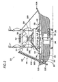
- FIG. 2 is a longitudinal sectional view to show an outline of the lottery machine 312 in the embodiment.
- a screw conveyor 320 is disposed in the stern 312B of the lottery machine 312. This screw conveyor 320 is an apparatus for transporting a lottery ball used for lottery upward through the inside of the lottery machine 312.
- the screw conveyor 320 is made up of a helical body 320A extending upward at a predetermined angle of inclination, a support plate 320B extending along the helical body 320A, and a lottery ball moving up motor 320C for running the helical body 320A.
- the helical body 320A is provided with a helical groove having a curvature radius larger than the radius of each lottery ball.
- the lottery ball moving up motor 320C is driven, the helical body 320A runs and a lottery ball is transported upward in a state in which the lottery ball is held between the helical groove formed on the helical body 320A and the support plate 320B.
- This means that the screw conveyor 320 is disposed outside the cabinet 313 and transports the lottery balls 302 so that the game player can visually recognize the lottery balls 302.
- a lottery ball guidance section 324 is disposed at the upper end of the screw conveyor 320.
- the lottery ball guidance section 324 is formed with a guidance passage (not shown).
- the lottery ball guidance section 324 guides the lottery balls transported by the screw conveyor 320 along the guidance passage.
- a lottery ball holding section 332 is disposed in an upper portion of the lottery machine 312.
- the lottery ball holding section 332 is formed of a permeable resin so that the game player, etc., can visually recognize the lottery balls in the lottery ball holding section 332. Thus, the remaining number of lottery balls can be explicitly indicated for the game player.
- the lottery ball holding section 332 is opened upward and holds the lottery balls guided from the lottery ball guidance section 324.
- the lottery ball holding section 332 is formed at the bottom with an opening for allowing one lottery ball to pass through (not shown).
- a cylindrical rotation body 328 is disposed below the lottery ball holding section 332.
- the rotation body 328 has a function of closing the opening formed at the bottom of the lottery ball holding section 332, so that the lottery balls held in the lottery ball holding section 332 are maintained in a state in which they are held.
- the rotation body 328 is formed with a holding hole for holding one lottery ball (not shown).
- a drive section made up of a rotation motor 326 (see FIG. 10), etc., (not shown) is disposed in an edge of the rotation body 328.
- the rotation body 328 rotates.
- the rotation body 328 is placed with the holding hole opened upward, allowing the one lottery ball held in the lottery ball holding section 332 to drop into the holding hole through the opening.
- the opening formed on the lottery ball holding section 332 is closed and one lottery ball is held in the holding hole.
- the rotation body 328 is formed of a permeable resin so that the game player can visually recognize the lottery ball held in the holding hole. Thus, the progress of the game can be explicitly indicated for the game player.
- a permeable lottery ball reception section 334 is disposed below the rotation body 328.
- the lottery ball reception section 334 is provided for receiving the lottery ball dropped from the holding hall of the rotation body 328 disposed above the lottery ball reception section 334.
- the lottery ball reception section 334 is formed with notches 334C and 334D (see FIG. 3) for inputting the received lottery ball into either of the two lottery disks 338 and 339. Since the lottery machine 312 has a rocking function, the lottery ball held in the lottery ball reception section 334 is guided into either of the two lottery disks 338 and 339 in response to the inclination angle.
- Slopes 336A and 336B each formed with an input path for allowing the lottery ball to pass through are disposed in the notches 334C and 334D of the lottery ball reception section 334 (see FIG. 3).
- the slopes 336A and 336B are provided for inputting the lottery ball held in the lottery ball reception section 334 into either of plane portions 338A and 339A (see FIG. 4).
- the slopes 336A and 336B are each formed with a permeable resin, so that the game player can visually recognize the lottery ball passing through the slope 336A, 336B.
- the two lottery disks 338 and 339 are disposed at the lower ends of the slopes 336A and 336B.
- the lottery disks 338 and 339 are formed with the plane portions 338A and 339A having horizontal planes relative to the cabinet 313 where the lottery ball can roll (see FIG. 4).
- a plurality of lottery holes 340 and 341 each for holding one lottery ball are formed on the surfaces of the plane portions 338A and 339A (see FIG. 4).
- a shutter 347 (see FIG. 10) is disposed on the bottoms of the lottery holes 340 and 341. The shutter 347 is controlled in a closed state during the game for holding the lottery balls entering the lottery holes 340 and 341. After the game is over, the shutter 347 is controlled in an open state, whereby the lottery balls entering the lottery holes 340 and 341 are ejected into the inside of the lottery machine 312.
- a ball entry detection sensor 349 (see FIG. 10) is disposed in each of the lottery holes 340 and 341. The ball entry detection sensor 349 detects the lottery ball entering any of the lottery holes.
- a collection section 345 formed with a first collection passage 344 and a second collection passage 350 is provided below the two lottery disks 338 and 339 of the lottery machine 312. As the shutter 347 (see FIG. 10) is controlled in the open state, the collection section 345 allows the lottery balls entering the lottery holes 340 and 341 to be received in the first collection passage 344.
- the collection section 345 is formed with inclined portions 353A and 353B for dropping the lottery balls received in the first collection passage 344.
- the second collection passage 350 extending in a horizontal direction is formed below the inclined portions 353A and 353B. Accordingly, the lottery balls entering the lottery holes 340 and 341 are guided into the second collection passage 350 along the first collection passage 344 and are held.
- a gate 352 is disposed in the second collection passage 350.
- the gate 352 is controlled so that it can be opened and closed.
- the lottery ball can pass through the nip between the second collection passage 350 and the lower end of the helical body 320A.
- the gate 352 is closed, the lottery ball cannot pass through the nip between the second collection passage 350 and the lower end of the helical body 320A.
- the lottery machine 312 is rocked so that the stern 312B side becomes lower than the stem 312A side, and the gate 352 is controlled in the open state, whereby the lottery balls held in the second collection passage 350 are introduced into the lower end of the helical body 320A.
- the lottery balls introduced into the lower end of the helical body 320A do not turn back into the second collection passage 350 and further the lottery balls held in the second collection passage 350 are not introduced into the lower end of the helical body 320A.
- a lottery ball passage detection sensor 351 is disposed between the gate 3532 and the lower end of the helical body 320A.
- the lottery ball passage detection sensor 351 is provided for detecting the number of the lottery balls introduced from the second collection passage 350 into the lower end of the helical body 320A through the gate 352. Therefore, if the number of the lottery balls passing through the gate 352 reaches a predetermined number as the lottery machine 312 is tilted so that the stern 312B side becomes lower than the stem 312A side and the gate 352 is controlled in the open state, the gate 352 is controlled in the closed state and a predetermined number of lottery balls are introduced into the lower end of the helical body 320A. After a predetermined number of lottery balls are introduced into the lower end of the helical body 320A, the lottery balls do not turn back into the second collection passage 350.
- the lottery machine 312 is provided with the rocking unit 346 and can be rocked and tilted on a rockshaft 348.
- a dot LED display 327 made up of a plurality of LEDs, etc., is disposed above the lottery ball holding section 332. The number of rounds in a game is displayed on the dot LED display 327.
- a START lamp 329 is disposed at the center of the lottery machine 312. When a lottery ball drops through the holding hole of the rotation body 328 into the lottery ball reception section 334, the lamp contained in the START lamp 329 is lighted, enabling the game player to visually recognize the character string START.
- the gaming machine 310 may be provided with a plurality of lighting units for making it possible to light up the sailer-shaped lottery machine 312 in various colors and making it possible to produce various effects in conjunction with the rock operation.
- FIG. 3 is a top view to show the lottery ball reception section 334 and the slopes 336A and 336B.
- the lottery ball reception section 334 described above is formed with a recess part 334A as shown in FIG. 3.
- the recess part 334A receives the lottery ball dropping from the holding hole of the rotation body 328 described above.
- the lottery ball reception section 334 is formed on a side face 334B with the two notches 334C and 334D.
- the lottery ball received in the recess part 334A rolls from either of the two notches 334C and 334D to the outside of the recess part 334A.
- the upper ends of the slopes 336A and 336B are disposed in the notches 334C and 334D.
- the lower ends of the slopes 336A and 336B are disposed above the lottery disks 338 and 339, as described above.
- the slopes 336A and 336B receive the lottery balls rolled from the notches 334C and 334D of the lottery ball reception section 334 to the outside of the lottery ball reception section 334 and guide the lottery balls into the lottery disks 338 and 339 respectively.
- the slopes 336A and 336B are disposed so as to input the lottery balls toward the same direction as the rotation direction of the lottery disks 338 and 339.
- the slopes 336A and 336B are formed linearly, but may be formed, for example, so as to have a curve rather than formed linearly.
- FIG. 4 is a top view to show the lottery machine 312.
- FIG. 5 is a perspective view to show the lottery disk 338.
- FIG. 6 is a top view to show the lottery disk 338.
- the lottery disk 339 which has the same configuration as the lottery disk 338, is not shown in FIG. 5 or 6 and will not be discussed.
- the two lottery disks 338 and 339 are disposed in the lottery machine 312 as described above.
- a plurality of lottery holes 340 and 341 can be made in the two lottery disks 338 and 339.
- the installation space in a gaming house can be used effectively without a fruitless space caused by making a large number of lottery holes. Accordingly, a large number of lottery holes can be provided and interest can be enhanced, for example, in such a manner that a wide variety of dividend can be provided.
- the lottery disks 338 and 339 are shaped each like a circle when viewed from above. They are disposed on the deck of the cabinet 313 for rotation.
- the lottery disks 338 and 339 are formed with the plane portions 338A and 339A for making it possible to roll lottery balls.
- the lottery disks 338 and 339 rotate roughly in the same direction (see arrows B1 and B2) as the direction in which lottery balls are input from the slopes 336A and 336B (see arrows A1 and A2).
- the lottery disk 338 rotates clockwise and the slope 336A is input clockwise as shown in FIG. 5.
- the speed does not become remarkably low. Therefore, the possibility that a lottery ball will enter any of the lottery holes 340, 341 in an extremely short time is low.
- a joint table 390 is provided between the lottery disks 338 and 339.
- the joint table 390 has a horizontal plane to the plane portions 338A and 339A of the lottery disks 338 and 339.
- a lottery ball can be rolled between the lottery disks 338 and 339.
- the lottery ball rolling speed does not become remarkably low.
- Guide parts 392 and 394 are provided between the lottery disks 338 and 339.
- the guide parts 392 and 394 are placed at such positions sandwiching the joint table 390 therebetween along the outer peripheries of the lottery disks 338 and 339.
- the guide parts 392 and 394 are shaped more convexly than the plane portions 338A and 339A of the lottery disks 338 and 339.
- Bank portions 396 and 398 are provided outside the lottery disks 338 and 339.
- the bank portions 396 and 398 are placed along the outer peripheries of the lottery disks 338 and 339.
- the bank portions 396 and 398 are shaped more convexly than the plane portions 338A and 339A of the lottery disks 338 and 339.
- the lottery disks 338 and 339 rotate in opposite directions as indicated by the arrows B1 and B2.
- the lottery ball input to the lottery disk 338 may roll from the lottery disk 338 through the joint table 390 to the lottery disk 339.
- the lottery ball input to the lottery disk 339 may roll from the lottery disk 339 through the joint table 390 to the lottery disk 338. Therefore, the lottery ball rolls between the lottery disks 338 and 339.
- the rocking unit 346 is disposed in the lottery machine 312, the cabinet 313 of the lottery machine 312 is rocked and a novel game hard to predict can be provided for the game player in such a manner that the lottery ball is rolled on the lottery disk 338, 339, for example, as the lottery ball rolls like a character 8 between the lottery disks 338 and 339; the interest in the game can be improved.
- the lottery disks 338 and 339, the joint table 390, the guide parts 392 and 394, and the bank portions 396 and 398 are surrounded by a fence formed of a permeable resin and it is not feared that lottery balls will roll outside the fence.
- the lottery disks 338 and 339 are formed with the 26 lottery holes 340 and the 26 lottery holes 341 respectively.
- Indicia having a spade or a heart as a first symbol is assigned to the lottery holes 340 made in the lottery disk 338, as shown in FIG. 5.
- A, 2 to 10, J, Q, and K of spades and A, 2 to 10, J, Q, and K of hearts are assigned to the lottery holes 340 made in the lottery disk 338.
- indicia having a club or a diamond as a first symbol is assigned to the lottery holes 341 made in the lottery disk 339.
- A, 2 to 10, J, Q, and K of clubs and A, 2 to 10, J, Q, and K of diamonds are assigned to the lottery holes 341 made in the lottery disk 339. That is, since any of the symbols are made the same kind, the game player can easily recognize desired indicia by visually recognizing the place where the lottery ball rolls; the player can be made still more eager and can be made to have a sense of anticipation and the interest in the game can be improved. For example, if a lottery ball rolls on the lottery disk 338, the game player can easily recognize that the first symbol is a space or a heart; if a lottery ball rolls on the lottery disk 339, the game player can easily recognize that the first symbol is a club or a diamond.
- indicia with the same kinds of first symbols is assigned to the lottery holes 340 and 341 made in the two lottery disks 338 and 339. Accordingly, for example, the game player can easily recognize desired indicia by visually recognizing the lottery disk 338, 339 where the lottery ball rolls; the player can be made still more eager and can be made to have a sense of anticipation and the interest in the game can be improved.
- the lottery disk 338 is formed with the lottery holes 340 along circumferences C1 and C2 with a rotation center point C0 as the center.
- the circumference C2 is inside the circumference C1.
- the 16 lottery holes are made along the circumference C1 and the 10 lottery holes are made along the circumference C2.
- A, 2 to 10, J, Q, and K of spades and A, 2 to 10, J, Q, and K of hearts are assigned to the 26 lottery holes 340, as described above.
- a and 2 to 8 of spades and A and 2 to 8 of hearts are assigned to the 16 lottery holes made along the circumference C1
- 9, 10, J, Q, and K of spades and 9, 10, J, Q, and K of hearts are assigned to the 10 lottery holes made along the circumference C2.
- the lottery disk 338 is formed with a plurality of convex parts 342 shaped more convexly than the plane portion 338A of the lottery disk 338, as shown in FIG. 5.
- the convex parts 342 are provided along a circumference C3 with the rotation center point C0 as the center, as shown in FIG. 6.
- the circumference C3 is positioned inside the innermost circumference C2 among the circumferences C1 and C2 along which the lottery holes are made. That is, the convex parts 342 are provided along the circumference C3 inside the innermost circumference C2 among the circumferences C1 and C2 so that they are adjacent to the lottery holes 340 formed along the circumference C2.
- a lottery ball collides with the convex part 342, rolling of the lottery ball is weakened, the rolling direction of the lottery ball can be changed, and the lottery balls enter evenly the lottery holes 340 formed along the circumference C2 and the lottery holes 340 formed along the circumference C1.
- a lottery can be held in such a manner that the lottery balls enter evenly a large number of lottery holes 340.
- a convex part 342A is provided in an area surrounded by tangents D1 and D2 to two adjacent lottery holes 340A and 340B along the circumference C2 and the circumference C3, as shown in FIG. 6.
- a lottery can be held in such a manner that the lottery balls enter evenly a large number of lottery holes 340.
- FIGS. 7A to 7G are longitudinal sectional views to show the second collection passage 350.
- the shutter 347 When a game is over, the shutter 347 is opened, allowing the lottery balls to drop through the lottery holes 340 and 341, as described above. After the expiration of a predetermined time interval, the lottery balls 302 are held in the second collection passage 350 as shown in FIG. 7A via the first collection passage 344.
- the cabinet 313 is tilted by the rocking unit 346 with the lottery balls 302 held in the second collection passage 350 of the collection section 345 described above as shown in FIG. 7A.
- the gate 352 provided in the second collection passage 350 is closed and thus the lottery balls 302 are held in the second collection passage 350 so that they are positioned on the gate 352 side.
- the gate 352 is controlled in the open state as shown in FIG.
- the lottery ball passage detection sensor 351 detects the number of the lottery balls 302 rolling toward the lower side of the helical body 320A. This means that the lottery ball passage detection sensor 351 detects the number of the lottery balls 302 introduced from the second collection passage 350 into the screw conveyor 320. In other words, the lottery ball passage detection sensor 351 detects the number of the lottery balls 302 passing through the gate 352.
- the gate 352 is controlled in the closed state as shown in FIG. 7D. Accordingly, a predetermined number of the lottery balls 302 roll toward the lower side of the helical body 320A as shown in FIG. 7E and are transported upward by the screw conveyor 320. This means that the lottery balls are placed in a state in which they can be input. In this state, the tilted cabinet 313 is restored to a horizontal position, namely, tilting the cabinet 313 is stopped, as shown in FIG. 7F. This means that the rocking unit 346 has a function to stop tilting the cabinet 313. As shown in FIG.
- the cabinet 313 (see FIG. 1) is tilted for introducing the lottery balls positioned in the second collection passage 350 toward the lower side of the helical body 320A.
- the lottery balls can be collected simply by tilting the cabinet 313, and the gaming machine 310 can be manufactured easily at low cost.
- the gaming machine 310 can be manufactured easily at low cost.
- a lottery ball ejection unit need not be provided for each of the lottery holes 340 and 341, and the gaming machine can be manufactured still more easily at low cost.
- FIG. 8 is a perspective view of the gaming terminal 314A.
- the gaming terminals 314B to 314J have each the same configuration as the gaming terminal 314A and therefore will not be discussed.
- the gaming terminal 314A is mainly made up of a display 370A, a touch sensor 372A (see FIG. 11), two dials 376A and 377A, a medal slot 378A, and a main control circuit 500A (see FIG. 11).
- the display 370A is provided in an upper portion of the gaming terminal 314A.
- the display 370A displays a bingo card image for a bingo game allocated to the game player, any other information, an optional game image, etc. In doing so, a game is advanced in a state in which the game player can visually recognize various pieces of information displayed on a screen (not shown) of the display 370A.
- the lottery machine 312 may be provided with a camera (not shown) for picking up the whole image of the lottery disks 338 and 339 and the picked-up image may be displayed on the display 370A, so that if the game player is hard to see either of the lottery disks 338 and 339, the game player can visually recognize the lottery disks 338 and 339.
- the display 370A is provided with a touch panel implemented mainly as the touch sensor 372A (see FIG. 11). Accordingly, a game environment for enabling the game player to enter various pieces of data and various commands simply by touching the display 370A can be provided for the game player.
- the touch sensor 372A (see FIG. 11) enables the game player to perform various types of entry operation, but any other operation mode may be adopted.
- a plurality of operation buttons may be provided for enabling the game player to perform various types of entry operation.
- a frontward projection portion 374A is provided on the game player side of the display 370A.
- the two dials 376A and 377A stacked on each other are provided on the top of the frontward projection portion 374A.
- a game environment for enabling the game player to perform operation difficult to perform simply by pressing a usual operation button or touching the touch panel can be provided for the game player.
- indicia assigned to a bingo box on the outer periphery of the matrix image can be moved to an adjacent bingo box along the outer periphery. If the game player wants to move second indicia continuously according to the mode, the game player must repeat operation several times simply by pressing a usual operation button or touching the touch panel, and the repeated operation is very cumbersome. Then, an input unit such as the dial 376A, 377A enables the game player to perform continuous operation with a single motion, so that a game high in operability can be provided for the game player. For an analog motion such as scrolling on the screen or moving a pointer, the dial 376A, 377A can be operated very easily, and a game high in operability can be provided for the game player.
- the medal slot 378A for inputting medals is provided on the right of the dials 376A and 377A.
- a medal sensor 380A (see FIG. 11) is disposed inside the medal slot 378A.
- the medal sensor 380A detects a medal being input to the medal slot 378A.
- the medal sensor 380A detects the medal being input.
- the main control circuit 500A (see FIG. 11) is disposed inside the frontward projection portion 374A for controlling the various components described above.
- the system configuration of the gaming machine 310 will be discussed with FIG. 9.
- the gaming machine 310 is mainly made up of a lottery machine controller 360 for controlling the lottery machine 312 and the gaming terminals 314A to 314J, as shown in FIG. 9.
- the lottery machine controller 360 is connected to the 10 gaming terminals 314A to 314J so that it can communicate with the gaming terminals 314A to 314J.
- the lottery machine controller 360 can transfer various pieces of data and various signals to and from the 10 gaming terminals 314A to 314J, thereby controlling the 10 gaming terminals 314A to 314J.
- the ball entry detection sensor 349 is connected to an interface circuit group 402 of a main control circuit 400, as shown in FIG. 10. When a lottery ball enters any of the lottery holes 340, 341, the ball entry detection sensor 349 supplies a predetermined signal through the interface circuit group 402 to an input/output bus 404.
- the input/output bus 404 inputs/outputs a data signal or an address signal to/from a central processing unit (CPU) 406.
- the lottery ball passage detection sensor 351 is also connected to the interface circuit group 402 of the main control circuit 400. When a lottery ball passes through the gate 352, the lottery ball passage detection sensor 351 supplies a predetermined signal through the interface circuit group 402 to the input/output bus 404.
- communication control circuits 414A to 414J are connected to the interface circuit group 402.
- the communication control circuits 414A to 414J are provided for connecting the lottery machine controller 360 and the gaming terminals 314A to 314J so that they can communicate with each other.
- ROM (read-only memory) 408 and RAM (random access memory) 410 are also connected to the input/output bus 404 described above.
- the ROM 408 records a control program for controlling processing concerning a game in the lottery machine controller 360. Further, the ROM 408 stores initial data for executing the control program, various programs, etc.
- the RAM 410 stores the values of variables and flags used in the above-described programs.
- an interface circuit group 412 is connected to the input/output bus 404.
- the various components can be controlled by the CPU 406, making it possible to drive the lottery machine 312 described above.
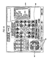
- the electrical configuration of the gaming terminal 314A of the gaming machine 310 will be discussed with FIG. 11.
- the gaming terminals 314B to 314J have each the same configuration as the gaming terminal 314A and therefore will not be discussed.
- the medal sensor 380A is connected to an interface circuit group 502A of the main control circuit 500A, as shown in FIG. 11.
- the medal sensor 380A supplies a predetermined signal through the interface circuit group 502A to an input/output bus 504A.
- the input/output bus 504A inputs/outputs a data signal or an address signal to/from a central processing unit (CPU) 506A.
- CPU central processing unit
- the touch sensor 372A is also connected to the interface circuit group 502A of the main control circuit 500A. If the touch sensor 372A detects the game player touching the display position of a command displayed on the display 370A, the touch sensor 372A supplies a signal corresponding to the command to the interface circuit group 502A.
- the dials 376A and 377A are connected to the interface circuit group 502A. If the game player turns the dial 376A or 377A, a signal corresponding to the turn angle is supplied to the interface circuit group 502A.
- a communication control circuit 514A is connected to the interface circuit group 502A.
- the communication control circuit 514A is provided for connecting the lottery machine controller 360 and the gaming terminal 314A so that they can communicate with each other.
- ROM (read-only memory) 508A and RAM (random acces s memory) 510A are also connected to the input/output bus 504A described above.
- the ROM 508A records a control program for assigning image code numbers to images corresponding to indicia consisting of first indicia and second indicia and controlling information provided by combining the images and the image code numbers and processing concerning a game in the gaming terminal 314A. Further, the ROM 508A stores initial data for executing the control program, a display control program in the display 370A, and the like.
- the RAM 510A stores the values of variables and flags used in the above-described programs.
- an interface circuit group 512A is connected to the input/output bus 504A.
- a speaker 586A and a hopper 588A are connected to the interface circuit group 512A.
- the interface circuit group 512A supplies a drive signal and drive power to control the components described above in response to the operation processing result in the CPU 506A.
- a display controller 600A is also connected to the interface circuit group 512A.
- the display controller 600A supplies an image signal to display an image to the display 370A based on an image display instruction supplied from the main control circuit 500A.
- FIGS. 12 to 15 show an example wherein the invention is applied to a bingo game using a bingo card having five X five bingo boxes.
- the gaming terminals 314A to 314J are the same gaming terminals and therefore in the description to follow, the gaming terminal 314A is adopted as the representative gaming machine.
- a predetermined number of numerals are drawn at a 1/25 probability from 25 numerals for a bingo card having five X five bingo boxes and when the drawn numeral exists on the bingo card, the bingo box corresponding to the drawn numeral is activated and then if five activated bingo boxes become complete on a vertical, horizontal, or diagonal line, a first combination is formed.
- a pack of cards (which may contain one or two jokers or may contain no jokers or a free spot activating a specific bingo box independently of drawing indicia may be used as a joker) is used for indicia in place of numerals as indicia used in the related art bingo game.
- Indicia is drawn at a 1/52 probability (which may be a 1/53 or 1/54 probability) in the lottery machine 312 (see FIG. 2).
- a 1/52 probability which may be a 1/53 or 1/54 probability
- the bingo box corresponding to the indicia is activated.
- first combinations for example, three, four, or five activated bingo boxes become complete on a specific line of the bingo card
- second combinations for example, one pair, two pairs, three of a kind, straight, flush, full house, four of a kind, straight flush, royal flush, five of a kind, etc.,
- Both a second combination and a first combination may be formed at the same time on a specific identical line of the bingo card, in which case both the dividend corresponding to the second combination and the dividend corresponding to the first combination were given to the player.
- operation of the gaming terminal 314A for the game player to play a game is always accepted in a touch panel manner except for operation of the dial 376A or 377A (see FIG. 8). That is, the touch sensor 372A (see FIG. 11) is provided on the surface of the display 370A, enabling the game player to operate the gaming terminal as intended by touching a predetermined touch part of the display 370A.
- the invention is not limited to the mode and an operation acceptance method independent of the touch panel manner may be adopted (in this case, the gaming terminal 314A need not be provided with the touch sensor 372A).
- predetermined switches may be provided for accepting operation of the game player.
- all operation of the game player may be accepted using the dials 336A and 337A.
- a standby screen displayed on the screen (not shown) of the display 370A of the gaming terminal 314A will be discussed with reference to FIG. 12.
- FIG. 12 shows a display example of an entry acceptance screen of game play in the gaming terminal 314A on the display 370A.
- the game player can operate touch parts 480 and 481 for accepting game play entry operation and the dials 336A and 337A (see FIG. 8).
- Medal input into the medal slot 378A (see FIG. 8) is ineffective and an input medal is returned to the game player from the medal payout opening 382A.
- Bingo boxes with a matrix of cards placed on a bingo card displayed on the display 370A are all displayed relatively dark or shaded to indicate that the bingo boxes are not yet drawn and not activated.
- activating a bingo box means that when a bingo box on which the same card as the card drawn in the lottery machine 312 exists, the bingo box is displayed so that the game player can distinguish the bingo box from other bingo boxes.
- the bingo box is activated, for example, the bingo box is displayed relatively light or is unshaded on the display 370A.
- the bingo boxes of the bingo card on the standby screen of the gaming terminal 314 are not activated as indicia is drawn in the lottery machine 321.
- the value of line odds or poker odds displayed on the screen (not shown) of the display 370A is not changed either as the game player performs some operation.
- Placement of the cards displayed on the bingo card having five X five bingo boxes displayed on the standby screen of the gaming terminal 314A differs from placement of the bingo card used for game play after game play entry.
- a demonstration screen is displayed and placement of the cards displayed on the bingo card is determined again after game play entry.
- game play entry is accepted.
- the display changes to a screen in FIG. 13.
- a screen after game play entry, displayed on the screen 5 (not shown) of the display 370A of the gaming terminal 314A will be discussed with reference to FIG. 13.
- FIG. 13 shows a screen where a bingo card made up of five X five bingo boxes with which cards are associated is determined and is displayed. At this time, the cards are placed so as to contain a predetermined second combination (for example, a second combination formed by five cards, namely, straight, flush, full house, straight flush, or royal flush) on a specific line. As a high-dividend combination is thus provided on the bingo card, the effect of enhancing a sense of anticipation of the game player is produced. Cards are placed at random on other bingo boxes than the predetermined second combination described above. Display of the touch parts 480 and 481 is erased and display of an entire reach state display section 483 (described later) appears.
- a predetermined second combination for example, a second combination formed by five cards, namely, straight, flush, full house, straight flush, or royal flush
- BET operation based on medal input of the game player and operation of the dials 376A and 377A are effective for a given time (for example, for a predetermined time of 45 seconds, etc., ) .
- a predetermined number of medals are bet
- the level of the line odds displayed in a line odds table 482 is raised (moved upward) and the displayed numeric value at the odds level of the line odds in the figure is raised (in FIG. 13, the hatched portion is positioned on the second row from the bottom of the line odds table 482 and the odds level is 2).
- the numeric value of the poker odds displayed in a poker odds table 484 is raised and the displayed numeric value at the odds level of the poker odds in the figure is raised (in the figure, the values of the odds for the second combinations are as displayed, and the odds level of the poker odds is 3).
- the odds level mentioned here is an index indicating which of levels into which the numeric values of odds are classified according to the greater-than, equal-to, less-than relationship the numeric values of the odds belong to. For example, the higher the numeric value of the odds level, the higher the numeric values of odds; or the higher the numeric value of the odds level, the lower the numeric values of odds.
- the bingo boxes of the bingo card displayed are also all displayed relatively dark or shaded to indicate that the bingo boxes are not yet drawn and not activated.
- the game player can rotate and move bingo boxes in an inner periphery 490 of the bingo card hatched by hatch lines raised to the right in FIG. 13 by operating the dial 376A and can rotate and move bingo boxes in an outer periphery 491 of the bingo card hatched by hatch lines lowered to the right in FIG. 13 by operating the dial 377A.
- the bingo boxes in the inner periphery 490 of the bingo card are also rotated and moved a predetermined amount counterclockwise with the center of the bingo card as the center.
- the game player turns the dial 376A counterclockwise in the amount corresponding to a move of one bingo box, for example, Q of heart positioned in the upper left corner of the inner periphery 490 of the bingo card in FIG. 13 moves to the place of J of heart and J of heart moves to the place of 3 of club.
- the bingo boxes move one at a time counterclockwise in such a manner.
- the game player operates the dial 377A, the bingo boxes in the outer periphery 491 of the bingo card are also rotated and moved in a similar manner. The game player can thus move the bingo boxes so as to rotate the bingo boxes as desired with the center of the bingo card as the center.
- the game player can perform the operation so long as the operation is accepted in the gaming terminal 314A.
- the strategy means the need for considering which of two pairs with a high possibility that the combination may be formed although the dividend is low and one pair with a low possibility that the combination may be formed although the dividend is high, for example, to move the bingo boxes.
- the drawing result is transmitted to the gaming terminal 314A, which then determines the same card as the drawn card exists on the bingo card displayed on the display 370A of the gaming terminal 314A. If it is determined that the same card as the drawn card exists on the bingo card displayed on the display 370A of the gaming terminal 314A, the bingo box of the bingo card on which the card is placed is displayed relatively light or unshaded to indicate that the bingo box is activated.
- FIG. 14 for example, seven bingo boxes on which 10 of diamond, J of heart, and the like are placed are displayed relatively light or unshaded to indicate that the bingo boxes are activated. While the lottery machine 312 executes a lottery a predetermined number of times, the bingo boxes activated by lottery remain displayed relatively light or unshaded to indicate that the bingo boxes are activated.
- the display 370A of the gaming terminal 314A during game play shown in FIG. 14 displays the next bingo box to be activated distinguishably for the game player based on the determination result as to if which bingo box is next activated, a first combination or a second combination will be formed.
- This display is produced in a manner in which the bingo box for forming a first combination or a second combination if the bingo box is next activated is displayed individually (reach state individual display) or in a manner in which the bingo boxes are displayed all at a time (entire reach state display).
- the reach state means a state in which there is a possibility that a first combination or a second combination will be formed as a specific bingo box is next activated.
- the reach state corresponding to the bingo boxes after move can be displayed in response to move of a bingo box, namely, each time a bingo box moves.
- the reach state individual display is as follows: If the bingo box on which K of heart is placed is activated, for example, in FIG. 14, three of a kind is formed and three bingo boxes become complete as a first combination and thus the game player is informed of the state in such a manner that the bingo box on which K of heart is placed is blinked. Further, as described later, if more than one bingo box exists for forming both or either of a second combination and a first combination if the bingo box is activated, blink display is switched for each of the bingo boxes, so that the game player can recognize that both or either of a second combination and a first combination is formed if which bingo box is activated.
- the entire reach state display is as follows: If the bingo boxes on which K of heart, A of spade, K of spade, and J of club are placed are activated, for example, in FIG. 14, both or either of a second combination and a first combination is formed and thus the bingo boxes are displayed at a time in the entire reach state display section 483 for informing the game player of the state.
- blink display 485 indicates at which positions in the whole bingo card the bingo boxes exist for forming both or either of a second combination and a first combination if the bingo boxes are activated.
- the blink display 485 indicates only the position of the bingo box in the bingo card for forming both or either of a second combination and a first combination if the bingo box is activated, and does not indicate the type of card placed on the bingo box, but the invention is not limited to the mode and the card type may be indicated.
- FIG. 14 if the bingo boxes on which K of heart, A of spade, K of spade, and J of club are placed are activated, both or either of a second combination and a first combination is formed, as described above in the reach state individual display.
- the situation in FIG. 15 is similar to that in FIG. 14, and FIGS. 15A to 15D show how the bingo boxes on which K of heart, A of spade, K of spade, and J of club are placed are blinked individually.
- FIG. 15A when K of heart is activated, a second combination of three of a kind is formed and three activated bingo boxes are arranged as a first combination and therefore the bingo box on which K of heart is placed is blinked as in blink display 486. After the blink display is produced for a predetermined time, a transition is made to the next state in FIG. 15B.
- FIG. 15B when A of spade is activated, a second combination of straight is formed and five activated bingo boxes are arranged as a first combination and therefore the bingo box on which A of spade is placed is blinked as in blink display 487. After the blink display is produced for a predetermined time, a transition is made to the next state in FIG. 15C.
- FIG. 15C when K of spade is activated, a second combination of three of a kind is formed and three activated bingo boxes are arranged as a first combination and therefore the bingo box on which K of spade is placed is blinked as in blink display 488. After the blink display is produced for a predetermined time, a transition is made to the next state in FIG. 15D.
- FIG. 15D when J of club is activated, a second combination of four of a kind is formed and four activated bingo boxes are arranged as a first combination and therefore the bingo box on which J of club is placed is blinked as in blink display 489. After the blink display is produced for a predetermined time, a transition is made again to the state in FIG. 15A.
- the blink display 486 in FIG. 15A, the blink display 487 in FIG. 15B, the blink display 488 in FIG. 15C, and the blink display 489 in FIG. 15D are thus produced repeatedly in this order each for the predetermined time in a transition manner of the blink display, whereby the game player can easily and precisely understand that it can be anticipated that both or either of a second combination and a first combination will be formed as which bingo box is activated.
- the game player has a sense of anticipation awakened and can play a game with peace of mind while sustaining interest in the game.
- the blink display transition may be made in the strength order of the first combinations and the second combinations (for example, a combination with a larger dividend may be made a stronger combination).
- a double down game screen displayed on the display 370A of the gaming terminal 314A will be discussed with reference to FIG. 16.
- the double down game is as follows: When the game player is given some dividend in a bingo game in the gaming machine 310, the game player bets the dividend.
- the dealer card selected under the control of the gaming terminal 314A is compared with one card selected by the game player from among a plurality of cards presented with the cards lying on their faces under the control of the gaming terminal 314A, and the game player or the dealer, who selects the stronger card, wins the game.
- the game player wins the game the gained dividend is doubled; on the other hand, when the dealer wins the game, the dividend gained by the game player is all confiscated.
- the face of the card selected by the dealer is first shown and the game player can select one from among four cards presented with the cards lying on their faces under the control of the gaming terminal 314A. If the game player touches the display of any desired card to select the card, the card is placed face up and is displayed and the game result of the double down game is determined. If the game player wins the game, he or she can specify whether or not another double down game is to be played.
- the game player When the game player is given some dividend in a bingo game in the gaming machine 310, the game player can make his or her decision as to whether or not a double down game is to be played.
- a game for enabling the game player to increase his or her gained dividend is provided aside from game play of the essential purpose in the gaming machine 310, whereby the game player finds out significance in gaining a dividend in game play of the essential purpose and further attempts to increase the gained dividend and therefore may be able to develop a large interest in playing a game in the gaming machine 310.
- step S100 game play preparation processing is performed. Specifically, a predetermined number of lottery balls held on the screw conveyor are moved to the lottery ball holding section 332. In addition, the CPU 406 performs various types of processing such as tilting the cabinet 313 at a predetermined angle. Upon completion of the processing, the process goes to step S101.
- the CPU 406 of the lottery machine 312 makes a lottery start determination.
- the CPU 406 determines whether or not a predetermined wait time has elapsed and the lottery start timing is reached. When the determination is YES, the process goes to step S102; when the determination is NO, the process goes to step S103.
- the CPU 406 of the lottery machine 312 transmits a lottery start signal-
- the CPU 406 transmits a lottery start signal to the gaming terminals 314A to 314J through the communication control circuits 414A to 414J.
- the process goes to step S104.
- the lottery start signal is received by the gaming terminal 314 at step S204 of processing of the main control circuit 500A of the gaming terminal 314 (described later).
- step S103 the CPU 406 of the lottery machine 312 consumes the wait time.
- the CPU 406 measures the time until the predetermined wait time has elapsed. Upon completion of the processing, the process returns to step S101.
- step S104 the CPU 406 of the lottery machine 312 consumes BET operation acceptance time.
- the CPU 406 measures the time until predetermined BET operation acceptance time has elapsed. Upon completion of the processing, the process returns to step S105.
- step S105 lottery disk rotation is started.
- the lottery disk rotation motors 335 and 337 are started for starting to rotate the plane portions 338A and 339A under the control of the main control circuit 400 of the lottery machine 312.
- the process goes to step S106.
- step S106 rocking the cabinet is started.
- the rocking unit 346 is started for starting to rock the cabinet of the lottery machine 312 under the control of the main control circuit 400 of the lottery machine 312.
- the process goes to step S107.
- step S107 one lottery ball is dropped.
- the rotation body 328 (see FIG. 1) is controlled under the control of the main control circuit 400 of the lottery machine 312 for dropping one lottery ball into the lottery ball reception section 334.
- the process goes to step S108.
- step S108 indicia is acquired.
- one of the ball entry detection sensors 349 provided in a one-to-one correspondence with the lottery holes 340 detects the lottery ball being entered under the control of the main control circuit 400 of the lottery machine 312 and the CPU 406 of the lottery machine 312 acquires the indicia corresponding to the lottery hole 340.
- the process goes to step S109.
- the CPU 406 of the lottery machine 312 transmits the indicia acquired at step S108 and information indicating what'th time the current lottery is.
- the CPU 406 transmits the indicia and information indicating what'th time the current lottery is to the gaming terminals 314A to 314J through the communication control circuits 414A to 414J.
- the process goes to step S110.
- the information indicating what'th time the current lottery is is counted by the CPU 406 and is stored in the RAM 410 (see FIG. 10). Further, the indicia and the information indicating what'th time the current lottery is are received by the gaming terminal 314 at step S214 of processing of the main control circuit 500A of the gaming terminal 314 (described later).
- the CPU 406 of the lottery machine 312 determines whether or not a lottery has been executed a predetermined number of times.
- the CPU 406 references the information indicating what'th time the current lottery is, stored in the RAM 410 and determines whether or not it reaches the predetermined number of times. when the determination is YES, the process goes to step S112; when the determination is NO, the process returns to step S107.
- step S112 rocking the cabinet is terminated.
- the rocking unit 346 is stopped to terminate rocking the cabinet of the lottery machine 312 under the control of the main control circuit 400 of the lottery machine 312.
- the process goes to step S113.
- step S113 rotating the lottery disks is terminated.
- the lottery disk rotationmotors 335 and 337 are stopped to terminate rotating the lottery disks 338 and 339 under the control of the main control circuit 400 of the lottery machine 312.
- the process returns to step S100.
- the gaming terminal 314 is initialized.
- the CPU 506A (see FIG. 11) of the gaming terminal 314 performs processing such as clearing various variables placed in the RAM 510A (see FIG. 11) and initializing display of the display 370A.
- the process goes to step S202.
- step S202 a demonstration screen is displayed. Upon completion of the processing, the process goes to step S203.
- step S203 game play entry operation is detected.
- the touch sensor 372A or the main control circuit 500A detects the operation of the game player under the control of the main control circuit 500A of the gaming terminal 314.
- the process goes to step S204.
- the lottery start signal is received.
- the CPU 506A of the gaming terminal 314 receives the lottery start signal transmitted by the lottery machine 312 at step S102 by the main control circuit 500A (see FIG. 11) of the gaming terminal 314 through the communication control circuit 514A. Upon completion of the processing, the process goes to step S209.
- a bingo card is generated and is displayed.
- the CPU 506A of the gaming terminal 314 selects a predetermined number of (for example, 25) pieces of display data from display data to display indicia (for example, cards, etc., ) stored in the ROM 508A, and places the selected display data as a matrix for display on the display 370A.
- the process goes to step S210.
- step S210 bingo box move operation is activated.
- the CPU 506A of the gaming terminal 314 turns on a bingo box move operation activation flag placed in the RAM 510A (see FIG. 11), thereby activating operation of the dials 376A and 377A for moving bingo boxes in the gaming terminal 314. Operation of the dials 376A and 377A for moving bingo boxes is effective so long as the bingo box move operation activation flag is on.
- the process goes to step S211.
- step S211 BET operation is accepted.
- the CPU 506A of the gaming terminal 314 processes information concerning the BET operation performed by the game player touching the screen (not shown) of the display 370A, information detected by the touch sensor 372A under the control of the main control circuit 500A of the gaming terminal 314, and stores BET information in the RAM 510A (see FIG. 11).
- the process goes to step S212.
- the dividend count is determined in response to the BET count.
- the CPU 506A of the gaming terminal 314 determines the dividend count in the game play based on the BET information stored in the RAM 510A (see FIG. 11) at step S211.
- the determination result is stored in the RAM 510A (see FIG. 11) and is displayed in a predetermined portion of the display 370A.
- the process goes to step S213.
- step S213 whether or not the BET acceptance time is out is determined.
- the CPU 506A of the gaming terminal 314 measures the time since step S209 was executed, and determines whether or not the measurement time reaches a predetermined time. when the determination is YES, the process goes to S214 in FIG. 18; when the determination is NO, the process returns to step S211.
- step S214 the indicia acquired at step S108 (see FIG. 17) by the CPU 406 of the lottery machine 312 and the information indicating what'th time the current lottery is, transmitted at S109 by the lottery machine 312 are received.
- the above-described information is received through the communication control circuit 514A under the control of the main control circuit 500A (see FIG. 11) of the gaming terminal 314.
- the CPU 506A of the gaming terminal 314 stores the indicia and the information indicating what'th time the current lottery is in the RAM 510A (see FIG. 11). Upon completion of the processing, the process goes to step S215.
- step S215 bingo box move operation inactivation processing is performed. This processing is described later in detail in “details of bingo box move operation inactivation processing.” Upon completion of the processing, the process goes to step S216.
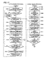
- the bingo card is searched for the indicia received at step S214 and if the indicia is found, the bingo box corresponding to the indicia is activated.
- the bingo card generated at step S209 and displayed on the display 370A is searched for the indicia received at step S214 and if the indicia is found, the activation flag placed in the RAM 510A (see FIG. 11), of the bingo box on which the indicia is placed is turned on. Further, the bingo box displayed on the display 370A is displayed relatively light or unshaded so that the bingo box can be distinguished from other bingo boxes.
- the process goes to step S217.
- step S217 winning combination determination processing is performed. This processing is described later in detail in “details of winning combination determination processing.” Upon completion of the processing, the process goes to step S218.
- step S2108 whether or not a winning combination is formed is determined.
- the CPU 506A of the gaming terminal 314 references the determination result at step S217 and determines whether or not a winning combination is formed.
- the determination is YES
- the process goes to step S219; when the determination is NO, the process goes to step S225.
- step S219 whether or not a double down game is to be played is determined.
- the CPU 506A of the gaming terminal 314 determines whether or not the touch sensor 372A detects the game player touching a predetermined touch part displayed on the display 370A to play a double down game under the control of the main control circuit 500A of the gaming terminal 314.
- the process goes to step S220; when the determination is NO, the process goes to step S223.
- step S220 double down game processing is performed. This processing is performed under the control of the main control circuit 500A of the gaming terminal 314 as previously described in the description of the double down game screen of the gaming terminal. Upon completion of the processing, the process goes to step S221.
- step S221 whether or not the game player wins the game is determined.
- the game result is determined as previously described in the description of the double down game screen of the gaming terminal under the control of the main control circuit 500A of the gaming terminal 314, and whether or not the game player wins the game is determined.
- the process goes to step S222; when the determination is NO, the process goes to step S224.
- step S222 the dividend of the game player is doubled.
- the CPU 506A of the gaming terminal 314 references the information of the dividend count gained by the game player, stored in the RAM 510A (see FIG. 11) and doubles it to update the information.
- the process goes to step S219.
- step S223 dividend payout processing is performed.
- the CPU 506A of the gaming terminal 314 references the information of the dividend count gained by the game player, stored in the RAM 510A (see FIG. 11) and the hopper 588A pays out as many medals as the information of the dividend count gained by the game player under the control of the main control circuit 500A.
- the process goes to step S201.
- step S224 the dividend count gained by the game player is cleared to 0.
- the CPU 506A of the gaming terminal 314 references the information of the dividend count gained by the game player, stored in the RAM 510A (see FIG. 11) and clears it to 0 to update the information.
- the process goes to step S201.
- step S225 reach determination processing is performed. This processing is described later in detail in “details of reach determination processing.” upon completion of the processing, the process goes to step S226.
- step S2266 whether or not a reach state is entered is determined. Based on the reach determination result at step S225, the CPU 506A of the gaming terminal 314 determines whether or not a reach state is entered wherein several bingo boxes of the bingo card displayed on the display 370A are activated and both or either of a first combination and a second combination is formed if an additional bingo box is activated. When the determination is YES, the process goes to step S227; when the determination is NO, the process goes to step S228.
- step S227 reach box notification start processing is performed. This processing is described later in detail in “details of reach box notification start processing. " Upon completion of the processing, the process goes to step S228.
- step S2208 whether or not indicia has been received a predetermined number of times is determined.
- the information indicating what'th time the current lottery is, stored in the RAM 410 (see FIG. 11) at step S214 is referenced and based on the information, whether or not indicia has been received the predetermined number of times is determined.
- the process goes to step S201; when the determination is NO, the process returns to step S214.
- the bingo box move operation inactivation processing will be discussed in detail with reference to FIG. 19.
- step S241 whether or not the information indicating what'th time the current lottery is, received at step S214 in FIG. 18 reaches a predetermined number of times is determined.
- the CPU 506A of the gaming terminal 314 determines the information and determines whether or not the information reaches a predetermined number of times (which may be three times or any other number of times, for example,).
- a predetermined number of times which may be three times or any other number of times, for example,.
- step S242 an advance notice of bingo box move operation inactivation is given.
- the main control circuit 500A of the gaming terminal 314 produces predetermined notice display of notification about performing processing of inactivating operation of the dials 376A and 377A for moving bingo boxes on the screen (not shown) of the display 370A.
- the process goes to step S243.
- step S243 a predetermined time is consumed.
- the CPU 506A of the gaming terminal 314 measures the time since step S242 was executed, and inhibits the process from going to the next step until a lapse of a predetermined time. Upon completion of the processing, the process goes to step S244.
- step S244 bingo box move operation is inactivated.
- the CPU 506A of the gaming terminal 314 turns off a dial operation activation flag placed in the RAM 510A (see FIG. 11), thereby inactivating operation of the dials 376A and 377A for moving bingo boxes in the gaming terminal 314.
- the subroutine is exited and the process returns to step S216 in FIG. 18.
- step S231 whether or not a first combination is formed is determined.
- the CPU 506A of the gaming terminal 314 determines combinations of the indicia stored in the RAM 510A (see FIG. 11) for forming the bingo card displayed on the display 370A, information concerning the positions of the bingo boxes on which the indicia is placed, and the activation flags corresponding to the indicia, and determines whether or not a first combination is held on a specific line of the bingo card.
- the determination is YES
- the process goes to step S232; when the determination is NO, the process goes to step S233.
- a first combination formation flag is turned on, information concerning every formed first combination and the bingo boxes is stored in the RAM, and the corresponding dividend count is stored in the RAM.
- the CPU 506A of the gaming terminal 314 turns on the first combination formation flag placed in the RAM 510A (see FIG. 11). Further, the CPU 506A stores information concerning every formed first combination and the bingo boxes in the RAM 510A. The CPU 506A determines the dividend count corresponding to every formed first combination and stores the determination result in the RAM 510A. Upon completion of the processing, the process goes to step S233.
- step S233 whether or not a second combination is formed is determined.
- the CPU 506A of the gaming terminal 314 determines combinations of the indicia stored in the RAM 510A (see FIG. 11) for forming the bingo card displayed on the display 370A, information concerning the positions of the bingo boxes on which the indicia is placed, and the activation flags corresponding to the indicia, and determines whether or not a second combination is held on a specific line of the bingo card.
- the determination is YES
- the process goes to step S234; when the determination is NO, immediately the subroutine is exited and the process returns to step S218 in FIG. 18.
- a second combination formation flag is turned on, information concerning every formed second combination and the bingo boxes is stored in the RAM, and the corresponding dividend count is stored in the RAM.
- the CPU 506A of the gaming terminal 314 turns on the second combination formation flag placed in the RAM 510A (see FIG. 11). Further, the CPU 506A stores information concerning every formed second combination and the bingo boxes in the RAM 510A. The CPU 506A determines the dividend count corresponding to every formed second combination and stores the determination result in the RAM 510A.
- the subroutine is exited and the process returns to step S218 in FIG. 18.
- first combination and formation of a second combination are determined separately, as described above.
- a dividend is given to each of the first combination and the second combination formed at the same time on the same specific line of the bingo card. This means that the dividend to the first combination and the dividend to the second combination are added up and the result is given to the game player. In doing so, the game player may be able to have a large anticipation sense for the possibility that combinations to which larger dividend is given may be formed on the specific line of the bingo card.
- the invention is not limited to the mode and it may be determined that only a first combination is formed or it may be determined that only a second combination is formed. In this case, the game player is given only the dividend to the first combination or only the dividend to the second combination.
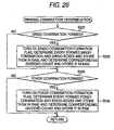
- the reach determination processing will be discussed in detail with reference to FIG. 21.
- step S251 whether or not a first combination is formed as a specific bingo box is activated is determined.
- the CPU 506A of the gaming terminal 314 determines combinations of the indicia stored in the RAM 510A (see FIG. 11) for forming the bingo card displayed on the display 370A, information concerning the positions of the bingo boxes on which the indicia is placed, and the activation flags corresponding to the indicia, and determines whether or not the situation is a situation in which a first combination can be formed on a specific line of the bingo card if a specific bingo box is activated.
- the determination is YES
- the process goes to step S252; when the determination is NO, the process goes to step S253.
- a first combination reach state flag is turned on and information concerning every reach box based on a first combination is stored in the RAM 510A.
- the one additional bingo box is the reach box.
- the CPU 506A of the gaming terminal 314 turns on the first combination reach state flag placed in the RAM 510A (see FIG. 11). Further, the Cpu 506A stores information concerning every reach box based on a first combination in the RAM 510A. Upon completion of the processing, the process goes to step S253.
- step S253 whether or not a second combination is formed as a specific bingo box is activated is determined.
- the CPU 506A of the gaming terminal 314 determines combinations of the indicia stored in the RAM 510A (see FIG. 11) for forming the bingo card displayed on the display 370A, information concerning the positions of the bingo boxes on which the indicia is placed, and the activation flags corresponding to the indicia, and determines whether or not the situation is a situation in which a second combination can be formed on a specific line of the bingo card if a specific bingo box is activated.
- the determination is YES
- the process goes to step S254; when the determination is NO, immediately the subroutine is exited and the process returns to step S226 in FIG. 18.
- a second combination reach state flag is turned on and information concerning every reach box based on a second combination is stored in the RAM.
- the CPU 506A of the gaming terminal 314 turns on the second combination reach state flag placed in the RAM 510A (see FIG. 11). Further, the CPU 506A stores information concerning every reach box based on a second combination in the RAM 510A.
- the subroutine is exited and the process returns to step S226 in FIG. 18.
- the reach box notification start processing will be discussed in detail with reference to FIG. 22.
- step S261 whether or not a reach box exists is determined.
- the CPU 506A of the gaming terminal 314 determines whether or not at least one of the first combination and second combination reach state flags stored in the RAM 510 (see FIG. 11) at step S252 and step S254 in FIG. 21 is on. when the determination is YES, the process goes to step S262; when the determination is NO, immediately the subroutine is exited and the process returns to step S228 in FIG. 18.
- step S262 display of all reach boxes in the entire reach state display section 483 so that the reach boxes can be distinguished at a time is started.
- the display controller 600A is driven under the control of the main control circuit 500A (see FIG. 11) of the gaming terminal 314 for starting to display all reach boxes stored in the RAM 510 (see FIG. 11) at both or either of step S252 and step S254 in FIG. 21 in the entire reach state display section 483 displayed on the display 370A.
- the process goes to step S263.
- step S263 repeated displaying all reach boxes in order so that the reach boxes can be distinguished individually is started.
- the display controller 600A is driven under the control of the main control circuit 500A (see FIG. 11) of the gaming terminal 314 for starting to repeatedly display in order all reach boxes stored in the RAM 510 (see FIG. 11) at both or either of step S252 and step S254 in FIG. 21 on the bingo card displayed on the display 370A so that the reach boxes can be distinguished individually.
- the situation of the display is as previously described in the "screen transition of the reach state individual display of the gaming terminal".
- the screen display of the reach box notification started at step S262 and step S263 continues until step S201 in FIG. 17 is executed for initializing the gaming terminal 314.
- the subroutine is exited and the process returns to step S228 in FIG. 18.
- step S263 is executed in the reach box notification start processing in FIG. 22, it is made possible for the gaming terminal 314 to repeatedly display in order all reach boxes on the screen (not shown) of the display 370A so that the reach boxes can be distinguished individually. That is, the reach box notification start processing, particularly step S263 is an example to show the reach notification manner in which the specific bingo boxes not activated are displayed individually in order in response to the determination of a combination determination unit in the gaming machine including a display unit for displaying a bingo card formed as a matrix of bingo boxes; an indicia display data storage unit for storing display data to display indicia of first indicia and of second indicia; a bingo card indicia determination unit for determining bingo card indicia selected from the indicia and associated with the bingo boxes; a lottery unit for drawing the indicia; a activation unit for activating the bingo box corresponding to the bingo card indicia when a comparison is made between the indicia drawn by the lottery unit and the bingo card in
- the gaming machine is as follows:
- the lottery disks 338 and 339 are provided on the portion corresponding to the deck of the lottery machine 312 imitating a ship, a plurality of holes in which balls can be entered are made in the surfaces of the lottery disks 338 and 339, the card associated with the hole in which a ball is entered as the ship is rocked is recognized, when the same card exists as the card displayed on the bingo card, the corresponding bingo box is activated, and predetermined dividend is given not only when a usual first combination is formed on a specific line of the bingo card according to the activated bingo box, but also when a second combination of the cards different from the first combination is formed.
- the invention is not limited to it.
- the invention can also be applied to a game play of keno (kino), etc., wherein, for example, a lottery is executed in a similar manner with numerals associated with holes and the dividend count is determined depending on how often a predetermined number of numerals previously selected by the game player have been drawn. That is, the configuration of the lottery machine 312 (see FIG. 1) in the embodiment can also be applied to any game play lottery machine if the game play is a game play for drawing indicia.
- the gaming machine of the invention includes a display unit for displaying a game card formed as a matrix of game boxes; an indicia display data storage unit for storing display data to display indicia of first indicia and of second indicia; a game card indicia determination unit for determining game card indicia selected from the indicia and associated with the game boxes; a lottery unit for drawing the indicia; a activation unit for activating the game box corresponding to the game card indicia when a comparison is made between the indicia drawn by the lottery unit and the game card indicia and coincides therebetween; and a winning combination determination unit for determining whether or not the game boxes activated by the activation unit form a predetermined game combination or whether or not the game card indicia corresponding to the game boxes activated by the activation unit forms a predetermined combination different from the predetermined game combination.
Abstract
Description
- This application is based upon and claims a priority from prior Japanese Patent Application No. 2003-316021 filed on September 8, 2003, the entire contents of which are incorporated herein by reference. This application is related to co-pending U.S. applications claiming priorities for JP-2003-316020 to filed on the even date with this application, international Application No. PCT/JP/03/11439, PCT/JP/03/11440, PCT/JP/03/11441, and filed on September 8, 2003 in Japan. The co-pending applications are expressly incorporated herein by reference.
- This invention relates to a gaming machine including a display unit for displaying information concerning game play and a lottery unit for drawing indicia, wherein the game result is determined based on the lottery result of the lottery unit.
- Hitherto, a bingo game has been played wherein using a bingo card having a matrix of boxes assigned various pieces of indicia, a player bores a hole in the box to which the indicia drawn as a win corresponds and the earliest player who completes boring holes in a vertical, horizontal, or diagonal row wins the game.
- Although the rule of the bingo game is simple, a large number of people form a liking for the bingo game regardless of age or sex because of the effects of making the player eager to bore holes in the bingo card and making the player have a sense of anticipation of completing one row by boring one additional hole unlike a gaming manner in which the game result is produced only by one drawing.
- Usually, a paper bingo card is used for the bingo game, but various electronically controlled gaming machines simulating the bingo game are developed. With such a gaming machine, a bingo card is displayed on a display as a matrix of bingo boxes and when the indicia drawn as a win exists on the bingo card, the corresponding bingo box is activated and is displayed so that it can be distinguished from other bingo boxes.
- A gaming machine for enabling the player to move a bingo box of a bingo card under a predetermined constraint to enhance the game amusement of the bingo game is proposed. (For example, refer to JP-A-2001-161888.)
- However, in the invention described above, the gaming machine does not include a display unit for indicating which bingo box is to be next activated to complete one row and thus the player must see the whole matrix of the bingo card carefully and if one row is completed by activating one additional bingo box, it is feared that the play may be unaware of it.
- It is an object of the invention to provide a gamingmachine for enabling a player to easily identify the lottery result to anticipate as the gaming machine includes means for displaying the possibility that the game play result desired by the player may be gained as specific indicia is drawn at the next lottery ( for example, indicating which bingo box is to be next activated to complete a first combination) for the player in a predetermined display manner.
- More particularly, according to the invention, the following is provided.
- According to a first aspect of the invention, there is provided a gaming machine including a display unit (for example,
main control circuit 500A,display controller 600A, anddisplay 370A later described with reference to FIG. 11, means for executing step S209 in FIG. 17, and the like) for displaying a game card (for example, a bingo card) formed as a matrix of game boxes (for example, a matrix of bingo boxes); an indicia display data storage unit (for example,ROM 508A later described with reference to FIG. 11, etc.,) for storing display data (for example, information provided by combining images and image code numbers as the image code numbers are assigned to the images corresponding to indicia consisting of first indicia and second indicia described later, etc.,) to display indicia of first indicia (for example, numerals of cards, etc.,) and different pieces of second indicia (for example, symbols of cards, etc.,); a game card indicia determination unit (for example,main control circuit 500A later described with reference to FIG. 11, means for executing step S209 in FIG. 17, and the like) for determining game card indicia selected from the indicia and associated with the game boxes; a lottery unit (for example,lottery machine 312 later described with reference to FIG. 2,main control circuit 400 later described with reference to FIG. 10, means for repeatedly executing steps S107 to S110 in FIG. 17, and the like) for drawing the indicia; a activation unit ( for example,main control circuit 500A,display controller 600A, and display 370A later described with reference to FIG. 11, means for executing step S216 in FIG. 18, and the like) for activating the game box corresponding to the game card indicia when a comparison is made between the indicia drawn by the lottery unit and the game card indicia and coincides there between; a combination determination unit (for example,main control circuit 500A later described with reference to FIG. 11, means for executing reach determination processing in FIG. 21 at step S225 in FIG. 18, and the like) for determining whether or not a combination of the game box activated by the activation unit and a specific game box not activated can form a predetermined first combination or whether or not a combination of the game card indicia corresponding to the game box activated by the activation unit and the game card indicia corresponding to a specific game box not activated can form a predetermined combination different from the predetermined first combination; and a condition notification unit (for example,main control circuit 500A,display controller 600A, anddisplay 370A later described with reference to FIG. 11, means for executing step S263 of reach box notification start processing in FIG. 22, and the like) for displaying the specific game boxes not activated individually and sequentially in response to the determination of the combination determination unit. - According to the first aspect of the invention, when it is determined that if a specific game box not activated is activated, a first combination can be formed or that a predetermined combination different from the first combination can be formed according to the game card indicia corresponding to a specific game box, the specific game boxes not activated are displayed individually in order so that the game boxes can be distinguished, thus enabling the player to easily identify the lottery result of the indicia to anticipate and play a game with peace of mind.
- According to a second aspect of the invention, there is provided the gaming machine according to the first aspect of the invention further includes an entire condition notification unit (for example,
main control circuit 500A,display controller 600A, anddisplay 370A later described with reference to FIG. 11, means for executing step S262 of reach box notification start processing in FIG. 22, and the like) for displaying the specific game boxes not activated at the same time in response to the determination of the combination determination unit as ide from the condition notification unit. - According to the second aspect of the invention, when it is determined that if a specific game box not activated is activated, a first combination can be formed or that a predetermined combination different from the first combination can be formed according to the game card indicia corresponding to a specific game box, the specific game boxes not activated are displayed all at the same time so that the game boxes can be distinguished aside from the condition notification unit. Thus, the player is given convenience of grasping all lottery results to anticipate.
- According to a third aspect of the invention, there is provided the gaming machine according to the second aspect of the invention further includes a game box move unit (for example,
main control circuit 500A later described with reference to FIG. 11,dials - According to the third aspect of the invention, the specific game boxes excepted to form a first combination or a predetermined combination different from the first combination as the game boxes are activated are displayed individually in order or all at the same time so that the game boxes can be distinguished regardless of a move of the game boxes by the game box move unit, thus enabling the player to easily identify and grasp the lottery result of the indicia to anticipate and play a game with peace of mind.
According to a fourth aspect of the invention, there is provided a gaming machine including a display unit for displaying a bingo card formed as a matrix of bingo boxes (for example,main control circuit 500A,display controller 600A, anddisplay 370A later described with reference to FIG. 11, means for executing step S209 in FIG. 17, and the like); indicia display data storage unit (for example,ROM 508A later described with reference to FIG. 11, etc.,) for storing display data (for example, information provided by combining images and image code numbers as the image code numbers are assigned to the images corresponding to indicia consisting of first indicia and second indicia described later, etc.,) to display an indicia of first indicia (for example, numerals of cards, etc.,) and different pieces of second indicia (for example, symbols of cards, etc.,); a bingo card indicia determination unit (for example,main control circuit 500A later described with reference to FIG. 11, means for executing step S209 in FIG. 17, and the like) for determining bingo card indicia selected from the indicia and associated with the bingo boxes; a lottery unit (for example,lottery machine 312 later described with reference to FIG. 2,main control circuit 400 later described with reference to FIG. 10, means for repeatedly executing steps S107 to S110 in FIG. 17, and the like) for drawing the indicia; a activation unit (for example,main control circuit 500A,display controller 600A, and display 370A later described with reference to FIG. 11, means for executing step S216 in FIG. 18, and the like) for activating the bingo box corresponding to the bingo card indicia when a comparison is made between the indicia drawn by the lottery unit and the bingo card indicia and coincides therebetween; a combination determination unit (for example,main control circuit 500A later described with reference to FIG. 11, means for executing reach determination processing in FIG. 21 at step S225 in FIG. 18, and the like) for determining whether or not a combination of the bingo box activated by the activation unit and a specific bingo box not activated can form a predetermined first combination or whether or not a combination of the bingo card indicia corresponding to the bingo box activated by the activation unit and the bingo card indicia corresponding to a specific bingo box not activated can form a predetermined combination different from the predetermined first combination; and a reach notification unit (for example,main control circuit 500A,display controller 600A, and display 370A later described with reference to FIG. 11, means for executing step S263 of reach box notification start processing in FIG. 22, and the like) for displaying the specific bingo boxes not activated individually in order in response to the determination of the combination determination unit. - According to the invention, in the gaming machine for determining the game play result based on the lottery result of the indicia, the possibility that the game play result desired by the player may be gained as specific indicia is drawn at the next lottery is displayed so that it can be distinguished, thereby enabling the player to easily identify the lottery result to anticipate and have a sense of anticipation awakened for the game play and thus can play a game with peace of mind.
- These and other objects and advantages of the present invention will be more fully apparent from the following detailed description taken in conjunction with the accompanying drawings, in which:
- FIG. 1 is a perspective view to show an outline of a
gaming machine 310 of an embodiment of the invention; - FIG. 2 is a longitudinal sectional view to show an outline
of a
lottery machine 312 of the embodiment of the invention; - FIG. 3 is a top view to show a lottery
ball reception section 334 of the embodiment of the invention; - FIG. 4 is a top view to show the
lottery machine 312 of the embodiment of the invention; - FIG. 5 is a perspective view to show a
lottery disk 338 of the embodiment of the invention; - FIG. 6 is a top view to show the
lottery disk 338 of the embodiment of the invention; - FIGS. 7A to 7G are longitudinal sectional views to show
a general view of a
second collection passage 350 in thegaming machine 310 of the embodiment of the invention; - FIG. 8 is a perspective view of a
gaming terminal 314A of the embodiment of the invention; - FIG. 9 is a block diagram to show the system configuration
of the
gaming machine 310 of the embodiment of the invention; - FIG. 10 is a block diagram to show control circuitry in
the
lottery machine 312 of the embodiment of the invention; - FIG. 11 is a block diagram to show control circuitry in
the
gaming terminal 314A of the embodiment of the invention; - FIG. 12 shows an example of a standby screen of the gaming
terminal, displayed on the screen of the
gaming terminal 314A of the embodiment of the invention; - FIG. 13 shows an example of a screen of the gaming terminal
after game play entry, displayed on the screen of the
gaming terminal 314A of the embodiment of the invention; - FIG. 14 shows an example of a screen of the gaming terminal
during game play, displayed on the screen of the
gaming terminal 314A of the embodiment of the invention; - FIGS. 15A to 15D show an example of screen transition
of reach state individual display, displayed on the screen of
the
gaming terminal 314A of the embodiment of the invention; - FIG. 16 shows an example of a double down game screen
of the gaming terminal, displayed on the screen of the
gaming terminal 314A of the embodiment of the invention; - FIG. 17 is a main flowchart of processing in main control
circuits of the
lottery machine 312 and thegaming terminal 314A of the embodiment of the invention; - FIG. 18 is a flowchart continued from FIG. 17;
- FIG. 19 is a flowchart of bingo box move operation inactivation processing;
- FIG. 20 is a flowchart of winning combination determination processing;
- FIG. 21 is a flowchart of reach determination processing; and
- FIG. 22 is a flowchart of reach box notification start processing.
-
- Referring now to the accompanying drawings (FIGS. 1 to 22), there is shown a preferred embodiment of the invention. In the description of the embodiment, the player is represented as game player.
Further, it is assumed that game boxes are represented as bingo boxes, and a game card is represented as a bingo card. - A
gaming machine 310 of the embodiment is a gaming machine for the game player to play a game using game media such as a card storing information of the game value given to the game player as well as coins, medals, game balls, and tokens. In the description that follows, however, it is assumed that the game player plays a game using medals. - To begin with, an outline of the gaming machine will be discussed with FIG. 1. FIG. 1 is a perspective view to show an outline of the gaming machine in the embodiment.
- As shown in FIG. 1, the
gaming machine 310 is made up of alottery machine 312 and a plurality ofgaming terminals 314. Thegaming machine 310 enables a plurality of game players to play a game at the same time with thegaming terminals 314A to 314J. - The
lottery machine 312 is implemented mainly as acabinet 313 imitating a ship disposed in the center of thegaming machine 310. Twolottery disks lottery machine 312. The twolottery disks lottery holes digits 2 to 10 and letters A, J, Q, and K as indicia are associated with the lottery holes 340 and 341. A lottery is held in response to any of the lottery holes 340 and 341 in which lottery balls are entered, and the game result is determined. A rocking unit 346 (see FIG. 2) is disposed in thelottery machine 312 and thecabinet 313 can be rocked so that astem 312A (see FIG. 2) and a stern 312B (see FIG. 2) are displaced up and down. - The
gaming terminals 314A to 314J are disposed on both gunwale sides of thelottery machine 312. In the embodiment, 10gaming terminals 314A to 314J are provided as shown in FIG. 1. Thegaming terminals 314A to 314J are formed withmedal payout openings 382A to 382J. Thegaming terminals 314F to 314H and the medal payout openings 382F to 382J hidden by thelottery machine 312 are not shown in FIG. 1. - In the embodiment, the 10
gaming terminals 314A to 314J are provided as a plurality of gaming machines, but the invention is not limited to the mode and another mode may be adopted. For example, a number of gaming terminals different from 10 may be provided or one gaming machine may be provided. - An outline of the
lottery machine 312 in thegaming machine 310 will be discussed with FIG. 2. FIG. 2 is a longitudinal sectional view to show an outline of thelottery machine 312 in the embodiment. - A
screw conveyor 320 is disposed in the stern 312B of thelottery machine 312. Thisscrew conveyor 320 is an apparatus for transporting a lottery ball used for lottery upward through the inside of thelottery machine 312. - The
screw conveyor 320 is made up of ahelical body 320A extending upward at a predetermined angle of inclination, asupport plate 320B extending along thehelical body 320A, and a lottery ball moving upmotor 320C for running thehelical body 320A. Thehelical body 320A is provided with a helical groove having a curvature radius larger than the radius of each lottery ball. As the lottery ball moving upmotor 320C is driven, thehelical body 320A runs and a lottery ball is transported upward in a state in which the lottery ball is held between the helical groove formed on thehelical body 320A and thesupport plate 320B. This means that thescrew conveyor 320 is disposed outside thecabinet 313 and transports thelottery balls 302 so that the game player can visually recognize thelottery balls 302. - One end of a lottery
ball guidance section 324 is disposed at the upper end of thescrew conveyor 320. The lotteryball guidance section 324 is formed with a guidance passage (not shown). The lotteryball guidance section 324 guides the lottery balls transported by thescrew conveyor 320 along the guidance passage. - A lottery
ball holding section 332 is disposed in an upper portion of thelottery machine 312. The lotteryball holding section 332 is formed of a permeable resin so that the game player, etc., can visually recognize the lottery balls in the lotteryball holding section 332. Thus, the remaining number of lottery balls can be explicitly indicated for the game player. The lotteryball holding section 332 is opened upward and holds the lottery balls guided from the lotteryball guidance section 324. The lotteryball holding section 332 is formed at the bottom with an opening for allowing one lottery ball to pass through (not shown). - A
cylindrical rotation body 328 is disposed below the lotteryball holding section 332. Therotation body 328 has a function of closing the opening formed at the bottom of the lotteryball holding section 332, so that the lottery balls held in the lotteryball holding section 332 are maintained in a state in which they are held. - The
rotation body 328 is formed with a holding hole for holding one lottery ball (not shown). A drive section made up of a rotation motor 326 (see FIG. 10), etc., (not shown) is disposed in an edge of therotation body 328. As the drive section is driven, therotation body 328 rotates. As therotation body 328 is rotated, therotation body 328 is placed with the holding hole opened upward, allowing the one lottery ball held in the lotteryball holding section 332 to drop into the holding hole through the opening. As therotation body 328 is further rotated, the opening formed on the lotteryball holding section 332 is closed and one lottery ball is held in the holding hole. As therotation body 328 is further rotated, the opening formed on the lotteryball holding section 332 is closed and the holding hole is opened downward, allowing the one lottery ball held in the holding hole to drop downward. Thus, one lottery ball held in the lotteryball holding section 332 is extracted and is dropped. Therotation body 328 is formed of a permeable resin so that the game player can visually recognize the lottery ball held in the holding hole. Thus, the progress of the game can be explicitly indicated for the game player. - A permeable lottery
ball reception section 334 is disposed below therotation body 328. The lotteryball reception section 334 is provided for receiving the lottery ball dropped from the holding hall of therotation body 328 disposed above the lotteryball reception section 334. Thus, the lottery ball dropped from the holding hall of therotation body 328 is held in the lotteryball reception section 334 so that the game player can visually recognize the lottery ball. The lotteryball reception section 334 is formed withnotches lottery disks lottery machine 312 has a rocking function, the lottery ball held in the lotteryball reception section 334 is guided into either of the twolottery disks -
Slopes notches slopes ball reception section 334 into either ofplane portions slopes slope - The two
lottery disks slopes lottery disks plane portions cabinet 313 where the lottery ball can roll (see FIG. 4). - A plurality of
lottery holes plane portions shutter 347 is controlled in a closed state during the game for holding the lottery balls entering the lottery holes 340 and 341. After the game is over, theshutter 347 is controlled in an open state, whereby the lottery balls entering the lottery holes 340 and 341 are ejected into the inside of thelottery machine 312. A ball entry detection sensor 349 (see FIG. 10) is disposed in each of the lottery holes 340 and 341. The ballentry detection sensor 349 detects the lottery ball entering any of the lottery holes. - A
collection section 345 formed with afirst collection passage 344 and asecond collection passage 350 is provided below the twolottery disks lottery machine 312. As the shutter 347 (see FIG. 10) is controlled in the open state, thecollection section 345 allows the lottery balls entering the lottery holes 340 and 341 to be received in thefirst collection passage 344. Thecollection section 345 is formed withinclined portions first collection passage 344. Further, thesecond collection passage 350 extending in a horizontal direction is formed below theinclined portions second collection passage 350 along thefirst collection passage 344 and are held. - A
gate 352 is disposed in thesecond collection passage 350. Thegate 352 is controlled so that it can be opened and closed. Thus, if thegate 352 is opened, the lottery ball can pass through the nip between thesecond collection passage 350 and the lower end of thehelical body 320A. On the other hand, if thegate 352 is closed, the lottery ball cannot pass through the nip between thesecond collection passage 350 and the lower end of thehelical body 320A. Thus, thelottery machine 312 is rocked so that the stern 312B side becomes lower than thestem 312A side, and thegate 352 is controlled in the open state, whereby the lottery balls held in thesecond collection passage 350 are introduced into the lower end of thehelical body 320A. As thegate 352 is controlled in the closed state, the lottery balls introduced into the lower end of thehelical body 320A do not turn back into thesecond collection passage 350 and further the lottery balls held in thesecond collection passage 350 are not introduced into the lower end of thehelical body 320A. - A lottery ball
passage detection sensor 351 is disposed between the gate 3532 and the lower end of thehelical body 320A. The lottery ballpassage detection sensor 351 is provided for detecting the number of the lottery balls introduced from thesecond collection passage 350 into the lower end of thehelical body 320A through thegate 352. Therefore, if the number of the lottery balls passing through thegate 352 reaches a predetermined number as thelottery machine 312 is tilted so that the stern 312B side becomes lower than thestem 312A side and thegate 352 is controlled in the open state, thegate 352 is controlled in the closed state and a predetermined number of lottery balls are introduced into the lower end of thehelical body 320A. After a predetermined number of lottery balls are introduced into the lower end of thehelical body 320A, the lottery balls do not turn back into thesecond collection passage 350. - The
lottery machine 312 is provided with the rockingunit 346 and can be rocked and tilted on arockshaft 348. - Further, a
dot LED display 327 made up of a plurality of LEDs, etc., is disposed above the lotteryball holding section 332. The number of rounds in a game is displayed on thedot LED display 327. ASTART lamp 329 is disposed at the center of thelottery machine 312. When a lottery ball drops through the holding hole of therotation body 328 into the lotteryball reception section 334, the lamp contained in theSTART lamp 329 is lighted, enabling the game player to visually recognize the character string START. Thegaming machine 310 may be provided with a plurality of lighting units for making it possible to light up the sailer-shapedlottery machine 312 in various colors and making it possible to produce various effects in conjunction with the rock operation. - The lottery
ball reception section 334 and theslopes ball reception section 334 and theslopes - The lottery
ball reception section 334 described above is formed with arecess part 334A as shown in FIG. 3. Therecess part 334A receives the lottery ball dropping from the holding hole of therotation body 328 described above. The lotteryball reception section 334 is formed on aside face 334B with the twonotches lottery machine 312 is rocked, the lottery ball received in therecess part 334A rolls from either of the twonotches recess part 334A. - The upper ends of the
slopes notches slopes lottery disks slopes notches ball reception section 334 to the outside of the lotteryball reception section 334 and guide the lottery balls into thelottery disks slopes lottery disks slopes - The
lottery machine 312 and thelottery disks lottery machine 312. FIG. 5 is a perspective view to show thelottery disk 338. FIG. 6 is a top view to show thelottery disk 338. Thelottery disk 339, which has the same configuration as thelottery disk 338, is not shown in FIG. 5 or 6 and will not be discussed. - As shown in FIG. 4, the two
lottery disks lottery machine 312 as described above. A plurality oflottery holes lottery disks - The
lottery disks cabinet 313 for rotation. Thelottery disks plane portions lottery disks slopes lottery disk 338 rotates clockwise and theslope 336A is input clockwise as shown in FIG. 5. Thus, when a lottery ball is rolled on thelottery disk - A joint table 390 is provided between the
lottery disks plane portions lottery disks lottery disks -
Guide parts lottery disks guide parts lottery disks guide parts plane portions lottery disks guide part -
Bank portions lottery disks bank portions lottery disks bank portions plane portions lottery disks slope lottery disk lottery disk bank portion lottery disk bank portion lottery disk - The
lottery disks lottery disk 338 may roll from thelottery disk 338 through the joint table 390 to thelottery disk 339. In contrast, the lottery ball input to thelottery disk 339 may roll from thelottery disk 339 through the joint table 390 to thelottery disk 338. Therefore, the lottery ball rolls between thelottery disks unit 346 is disposed in thelottery machine 312, thecabinet 313 of thelottery machine 312 is rocked and a novel game hard to predict can be provided for the game player in such a manner that the lottery ball is rolled on thelottery disk character 8 between thelottery disks lottery disks guide parts bank portions - The
lottery disks lottery holes 340 and the 26lottery holes 341 respectively. Indicia having a spade or a heart as a first symbol is assigned to the lottery holes 340 made in thelottery disk 338, as shown in FIG. 5. Specifically, A, 2 to 10, J, Q, and K of spades and A, 2 to 10, J, Q, and K of hearts are assigned to the lottery holes 340 made in thelottery disk 338. On the other hand, indicia having a club or a diamond as a first symbol is assigned to the lottery holes 341 made in thelottery disk 339. specifically, A, 2 to 10, J, Q, and K of clubs and A, 2 to 10, J, Q, and K of diamonds are assigned to the lottery holes 341 made in thelottery disk 339. That is, since any of the symbols are made the same kind, the game player can easily recognize desired indicia by visually recognizing the place where the lottery ball rolls; the player can be made still more eager and can be made to have a sense of anticipation and the interest in the game can be improved. For example, if a lottery ball rolls on thelottery disk 338, the game player can easily recognize that the first symbol is a space or a heart; if a lottery ball rolls on thelottery disk 339, the game player can easily recognize that the first symbol is a club or a diamond. That is, indicia with the same kinds of first symbols is assigned to the lottery holes 340 and 341 made in the twolottery disks lottery disk - The
lottery disk 338 is formed with the lottery holes 340 along circumferences C1 and C2 with a rotation center point C0 as the center. The circumference C2 is inside the circumference C1. The 16 lottery holes are made along the circumference C1 and the 10 lottery holes are made along the circumference C2. A, 2 to 10, J, Q, and K of spades and A, 2 to 10, J, Q, and K of hearts are assigned to the 26lottery holes 340, as described above. Specifically, A and 2 to 8 of spades and A and 2 to 8 of hearts are assigned to the 16 lottery holes made along the circumference C1, and 9, 10, J, Q, and K of spades and 9, 10, J, Q, and K of hearts are assigned to the 10 lottery holes made along the circumference C2. - The
lottery disk 338 is formed with a plurality ofconvex parts 342 shaped more convexly than theplane portion 338A of thelottery disk 338, as shown in FIG. 5. Theconvex parts 342 are provided along a circumference C3 with the rotation center point C0 as the center, as shown in FIG. 6. The circumference C3 is positioned inside the innermost circumference C2 among the circumferences C1 and C2 along which the lottery holes are made. That is, theconvex parts 342 are provided along the circumference C3 inside the innermost circumference C2 among the circumferences C1 and C2 so that they are adjacent to the lottery holes 340 formed along the circumference C2. Accordingly, for example, a lottery ball collides with theconvex part 342, rolling of the lottery ball is weakened, the rolling direction of the lottery ball can be changed, and the lottery balls enter evenly the lottery holes 340 formed along the circumference C2 and the lottery holes 340 formed along the circumference C1. Thus, a lottery can be held in such a manner that the lottery balls enter evenly a large number of lottery holes 340. - Preferably, a
convex part 342A is provided in an area surrounded by tangents D1 and D2 to twoadjacent lottery holes lottery holes convex part 342A, rolling of the lottery ball is weakened, the rolling direction of the lottery ball can be changed, the possibility that the lottery ball will enter thelottery hole - The
collection section 345 in thelottery machine 312 described above will be discussed with FIG. 7. FIGS. 7A to 7G are longitudinal sectional views to show thesecond collection passage 350. - When a game is over, the
shutter 347 is opened, allowing the lottery balls to drop through the lottery holes 340 and 341, as described above. After the expiration of a predetermined time interval, thelottery balls 302 are held in thesecond collection passage 350 as shown in FIG. 7A via thefirst collection passage 344. Thecabinet 313 is tilted by the rockingunit 346 with thelottery balls 302 held in thesecond collection passage 350 of thecollection section 345 described above as shown in FIG. 7A. In this case, as shown in FIG. 7B, thegate 352 provided in thesecond collection passage 350 is closed and thus thelottery balls 302 are held in thesecond collection passage 350 so that they are positioned on thegate 352 side. Thegate 352 is controlled in the open state as shown in FIG. 7C, whereby thelottery balls 302 positioned in thesecond collection passage 350 roll toward the lower side of thehelical body 320A. That is, thecabinet 313 is tilted for introducing thelottery balls 302 positioned in thesecond collection passage 350 into thescrew conveyor 320. If thelottery balls 302 thus roll toward the lower side of thehelical body 320A, the lottery ballpassage detection sensor 351 detects the number of thelottery balls 302 rolling toward the lower side of thehelical body 320A. This means that the lottery ballpassage detection sensor 351 detects the number of thelottery balls 302 introduced from thesecond collection passage 350 into thescrew conveyor 320. In other words, the lottery ballpassage detection sensor 351 detects the number of thelottery balls 302 passing through thegate 352. If the number of thelottery balls 302 detected by the lottery ballpassage detection sensor 351 reaches a predetermined number, thegate 352 is controlled in the closed state as shown in FIG. 7D. Accordingly, a predetermined number of thelottery balls 302 roll toward the lower side of thehelical body 320A as shown in FIG. 7E and are transported upward by thescrew conveyor 320. This means that the lottery balls are placed in a state in which they can be input. In this state, the tiltedcabinet 313 is restored to a horizontal position, namely, tilting thecabinet 313 is stopped, as shown in FIG. 7F. This means that the rockingunit 346 has a function to stop tilting thecabinet 313. As shown in FIG. 7F, thelottery balls 302 rolling toward the lower side of thehelical body 320A do not turn back. If the cabinet is tilted in the opposite direction, thelottery balls 302 rolling toward the lower side of thehelical body 320A do not turn back either, of course, as shown in FIG. 7G. - Accordingly, the cabinet 313 (see FIG. 1) is tilted for introducing the lottery balls positioned in the
second collection passage 350 toward the lower side of thehelical body 320A. Thus, the lottery balls can be collected simply by tilting thecabinet 313, and thegaming machine 310 can be manufactured easily at low cost. Particularly, inalarge-sized gaming machine of a bingo game, etc., it is necessary to save space as much as possible; according to the invention, still more space saving can be accomplished. A lottery ball ejection unit need not be provided for each of the lottery holes 340 and 341, and the gaming machine can be manufactured still more easily at low cost. - The
gaming terminal 314A in thegaming machine 310 will be discussed with FIG. 8. FIG. 8 is a perspective view of thegaming terminal 314A. Thegaming terminals 314B to 314J have each the same configuration as thegaming terminal 314A and therefore will not be discussed. - The
gaming terminal 314A is mainly made up of adisplay 370A, atouch sensor 372A (see FIG. 11), twodials medal slot 378A, and amain control circuit 500A (see FIG. 11). - The
display 370A is provided in an upper portion of thegaming terminal 314A. Thedisplay 370A displays a bingo card image for a bingo game allocated to the game player, any other information, an optional game image, etc. In doing so, a game is advanced in a state in which the game player can visually recognize various pieces of information displayed on a screen (not shown) of thedisplay 370A. - Further, the
lottery machine 312 may be provided with a camera (not shown) for picking up the whole image of thelottery disks display 370A, so that if the game player is hard to see either of thelottery disks lottery disks - The
display 370A is provided with a touch panel implemented mainly as thetouch sensor 372A (see FIG. 11). Accordingly, a game environment for enabling the game player to enter various pieces of data and various commands simply by touching thedisplay 370A can be provided for the game player. - In the embodiment, the
touch sensor 372A (see FIG. 11) enables the game player to perform various types of entry operation, but any other operation mode may be adopted. For example, a plurality of operation buttons may be provided for enabling the game player to perform various types of entry operation. - A
frontward projection portion 374A is provided on the game player side of thedisplay 370A. The twodials frontward projection portion 374A. Using thedials - For example, in the embodiment, in a matrix image for a bingo game displayed on the
display 370A, indicia assigned to a bingo box on the outer periphery of the matrix image can be moved to an adjacent bingo box along the outer periphery. If the game player wants to move second indicia continuously according to the mode, the game player must repeat operation several times simply by pressing a usual operation button or touching the touch panel, and the repeated operation is very cumbersome. Then, an input unit such as thedial dial - The
medal slot 378A for inputting medals is provided on the right of thedials medal sensor 380A (see FIG. 11) is disposed inside themedal slot 378A. Themedal sensor 380A detects a medal being input to themedal slot 378A. Thus, if the game player inputs a medal into themedal slot 378A, themedal sensor 380A detects the medal being input. - The
main control circuit 500A (see FIG. 11) is disposed inside thefrontward projection portion 374A for controlling the various components described above. - The system configuration of the
gaming machine 310 will be discussed with FIG. 9. - The
gaming machine 310 is mainly made up of alottery machine controller 360 for controlling thelottery machine 312 and thegaming terminals 314A to 314J, as shown in FIG. 9. - The
lottery machine controller 360 is connected to the 10gaming terminals 314A to 314J so that it can communicate with thegaming terminals 314A to 314J. Thelottery machine controller 360 can transfer various pieces of data and various signals to and from the 10gaming terminals 314A to 314J, thereby controlling the 10gaming terminals 314A to 314J. - The electrical configuration of the
lottery machine 312 of thegaming machine 310 will be discussed with FIG. 10. - The ball
entry detection sensor 349 is connected to aninterface circuit group 402 of amain control circuit 400, as shown in FIG. 10. When a lottery ball enters any of the lottery holes 340, 341, the ballentry detection sensor 349 supplies a predetermined signal through theinterface circuit group 402 to an input/output bus 404. The input/output bus 404 inputs/outputs a data signal or an address signal to/from a central processing unit (CPU) 406. - The lottery ball
passage detection sensor 351 is also connected to theinterface circuit group 402 of themain control circuit 400. When a lottery ball passes through thegate 352, the lottery ballpassage detection sensor 351 supplies a predetermined signal through theinterface circuit group 402 to the input/output bus 404. - Further,
communication control circuits 414A to 414J are connected to theinterface circuit group 402. Thecommunication control circuits 414A to 414J are provided for connecting thelottery machine controller 360 and thegaming terminals 314A to 314J so that they can communicate with each other. - ROM (read-only memory) 408 and RAM (random access memory) 410 are also connected to the input/
output bus 404 described above. TheROM 408 records a control program for controlling processing concerning a game in thelottery machine controller 360. Further, theROM 408 stores initial data for executing the control program, various programs, etc. TheRAM 410 stores the values of variables and flags used in the above-described programs. - Further, an
interface circuit group 412 is connected to the input/output bus 404. Connected to theinterface circuit group 412 are the lottery ball moving upmotor 320C, therotation motor 326, lotterydisk rotation motors shutter 347, the rockingunit 346, and thegate 352. Accordingly, the various components can be controlled by theCPU 406, making it possible to drive thelottery machine 312 described above. - The electrical configuration of the
gaming terminal 314A of thegaming machine 310 will be discussed with FIG. 11. Thegaming terminals 314B to 314J have each the same configuration as thegaming terminal 314A and therefore will not be discussed. - The
medal sensor 380A is connected to aninterface circuit group 502A of themain control circuit 500A, as shown in FIG. 11. When a medal is input through themedal slot 378A, themedal sensor 380A supplies a predetermined signal through theinterface circuit group 502A to an input/output bus 504A. The input/output bus 504A inputs/outputs a data signal or an address signal to/from a central processing unit (CPU) 506A. - The
touch sensor 372A is also connected to theinterface circuit group 502A of themain control circuit 500A. If thetouch sensor 372A detects the game player touching the display position of a command displayed on thedisplay 370A, thetouch sensor 372A supplies a signal corresponding to the command to theinterface circuit group 502A. - The
dials interface circuit group 502A. If the game player turns thedial interface circuit group 502A. - Further, a
communication control circuit 514A is connected to theinterface circuit group 502A. Thecommunication control circuit 514A is provided for connecting thelottery machine controller 360 and thegaming terminal 314A so that they can communicate with each other. - ROM (read-only memory) 508A and RAM (random acces s memory) 510A are also connected to the input/
output bus 504A described above. TheROM 508A records a control program for assigning image code numbers to images corresponding to indicia consisting of first indicia and second indicia and controlling information provided by combining the images and the image code numbers and processing concerning a game in thegaming terminal 314A. Further, theROM 508A stores initial data for executing the control program, a display control program in thedisplay 370A, and the like. TheRAM 510A stores the values of variables and flags used in the above-described programs. - Further, an
interface circuit group 512A is connected to the input/output bus 504A. Aspeaker 586A and ahopper 588A are connected to theinterface circuit group 512A. Theinterface circuit group 512A supplies a drive signal and drive power to control the components described above in response to the operation processing result in theCPU 506A. - A
display controller 600A is also connected to theinterface circuit group 512A. Thedisplay controller 600A supplies an image signal to display an image to thedisplay 370A based on an image display instruction supplied from themain control circuit 500A. - FIGS. 12 to 15 show an example wherein the invention is applied to a bingo game using a bingo card having five X five bingo boxes. The
gaming terminals 314A to 314J are the same gaming terminals and therefore in the description to follow, thegaming terminal 314A is adopted as the representative gaming machine. - The following related art bingo game is mainstream: A predetermined number of numerals are drawn at a 1/25 probability from 25 numerals for a bingo card having five X five bingo boxes and when the drawn numeral exists on the bingo card, the bingo box corresponding to the drawn numeral is activated and then if five activated bingo boxes become complete on a vertical, horizontal, or diagonal line, a first combination is formed. In the embodiment, a pack of cards (which may contain one or two jokers or may contain no jokers or a free spot activating a specific bingo box independently of drawing indicia may be used as a joker) is used for indicia in place of numerals as indicia used in the related art bingo game. Indicia is drawn at a 1/52 probability (which may be a 1/53 or 1/54 probability) in the lottery machine 312 (see FIG. 2). When the same indicia as the drawn indicia exists on the bingo card displayed on the display screen of the
gaming terminal 314A, the bingo box corresponding to the indicia is activated. In addition to the related art first combinations (for example, three, four, or five activated bingo boxes become complete on a specific line of the bingo card), second combinations (for example, one pair, two pairs, three of a kind, straight, flush, full house, four of a kind, straight flush, royal flush, five of a kind, etc.,) may be formed according to the activated bingo boxes, and the dividend responsive to the first' combination or the second combination is given to the player. Both a second combination and a first combination may be formed at the same time on a specific identical line of the bingo card, in which case both the dividend corresponding to the second combination and the dividend corresponding to the first combination were given to the player. However, the probability that a bingo box is activated became lower and the possibility that a first combination is formed became lower than those in the related art bingo game. Then, although a first combination was formed when five activated bingo boxes became complete on a vertical, horizontal, or diagonal line of the related art bingo card, a first combination is assumed to be formed if not only five, but also three or four activated bingo boxes become complete. - In the embodiment, operation of the
gaming terminal 314A for the game player to play a game is always accepted in a touch panel manner except for operation of thedial touch sensor 372A (see FIG. 11) is provided on the surface of thedisplay 370A, enabling the game player to operate the gaming terminal as intended by touching a predetermined touch part of thedisplay 370A. However, the invention is not limited to the mode and an operation acceptance method independent of the touch panel manner may be adopted (in this case, thegaming terminal 314A need not be provided with thetouch sensor 372A). For example, predetermined switches may be provided for accepting operation of the game player. Alternatively, all operation of the game player may be accepted using thedials 336A and 337A. - A standby screen displayed on the screen (not shown) of the
display 370A of thegaming terminal 314A will be discussed with reference to FIG. 12. - FIG. 12 shows a display example of an entry acceptance screen of game play in the
gaming terminal 314A on thedisplay 370A. In the screen, the game player can operatetouch parts dials 336A and 337A (see FIG. 8). Medal input into themedal slot 378A (see FIG. 8) is ineffective and an input medal is returned to the game player from themedal payout opening 382A. Bingo boxes with a matrix of cards placed on a bingo card displayed on thedisplay 370A are all displayed relatively dark or shaded to indicate that the bingo boxes are not yet drawn and not activated. In the description to follow, activating a bingo box means that when a bingo box on which the same card as the card drawn in thelottery machine 312 exists, the bingo box is displayed so that the game player can distinguish the bingo box from other bingo boxes. As the bingo box is activated, for example, the bingo box is displayed relatively light or is unshaded on thedisplay 370A. The bingo boxes of the bingo card on the standby screen of thegaming terminal 314 are not activated as indicia is drawn in the lottery machine 321. The value of line odds or poker odds displayed on the screen (not shown) of thedisplay 370A is not changed either as the game player performs some operation. - Placement of the cards displayed on the bingo card having five X five bingo boxes displayed on the standby screen of the
gaming terminal 314A differs from placement of the bingo card used for game play after game play entry. Here, a demonstration screen is displayed and placement of the cards displayed on the bingo card is determined again after game play entry. - As the game player touches the
touch part gaming terminal 314A, the display changes to a screen in FIG. 13. - A screen after game play entry, displayed on the screen 5 (not shown) of the
display 370A of thegaming terminal 314A will be discussed with reference to FIG. 13. - FIG. 13 shows a screen where a bingo card made up of five X five bingo boxes with which cards are associated is determined and is displayed. At this time, the cards are placed so as to contain a predetermined second combination (for example, a second combination formed by five cards, namely, straight, flush, full house, straight flush, or royal flush) on a specific line. As a high-dividend combination is thus provided on the bingo card, the effect of enhancing a sense of anticipation of the game player is produced. Cards are placed at random on other bingo boxes than the predetermined second combination described above. Display of the
touch parts dials - On the screen (not shown) of the
display 370A of the gaming terminal after game play entry, the bingo boxes of the bingo card displayed are also all displayed relatively dark or shaded to indicate that the bingo boxes are not yet drawn and not activated. - If BET operation based on medal input of the game player and operation of the
dials inner periphery 490 of the bingo card hatched by hatch lines raised to the right in FIG. 13 by operating thedial 376A and can rotate and move bingo boxes in anouter periphery 491 of the bingo card hatched by hatch lines lowered to the right in FIG. 13 by operating thedial 377A. Specifically, as the game player turns thedial 376A counterclockwise a predetermined amount, the bingo boxes in theinner periphery 490 of the bingo card are also rotated and moved a predetermined amount counterclockwise with the center of the bingo card as the center. For example, if the game player turns thedial 376A counterclockwise in the amount corresponding to a move of one bingo box, for example, Q of heart positioned in the upper left corner of theinner periphery 490 of the bingo card in FIG. 13 moves to the place of J of heart and J of heart moves to the place of 3 of club. The bingo boxes move one at a time counterclockwise in such a manner. If the game player operates thedial 377A, the bingo boxes in theouter periphery 491 of the bingo card are also rotated and moved in a similar manner. The game player can thus move the bingo boxes so as to rotate the bingo boxes as desired with the center of the bingo card as the center. The game player can perform the operation so long as the operation is accepted in thegaming terminal 314A. As such operation is made possible, it becomes necessary for the game player not only to move the bingo boxes so as to place the bingo cards in a high possibility that a first combination may be formed, but also to consider a second combination; a strategy is required. The strategy means the need for considering which of two pairs with a high possibility that the combination may be formed although the dividend is low and one pair with a low possibility that the combination may be formed although the dividend is high, for example, to move the bingo boxes. - An example of display of the
display 370A of thegaming terminal 314 during game play will be discussed with reference to FIG. 14. - when a card is drawn by the
lottery machine 312, the drawing result is transmitted to thegaming terminal 314A, which then determines the same card as the drawn card exists on the bingo card displayed on thedisplay 370A of thegaming terminal 314A. If it is determined that the same card as the drawn card exists on the bingo card displayed on thedisplay 370A of thegaming terminal 314A, the bingo box of the bingo card on which the card is placed is displayed relatively light or unshaded to indicate that the bingo box is activated. - In FIG. 14, for example, seven bingo boxes on which 10 of diamond, J of heart, and the like are placed are displayed relatively light or unshaded to indicate that the bingo boxes are activated. While the
lottery machine 312 executes a lottery a predetermined number of times, the bingo boxes activated by lottery remain displayed relatively light or unshaded to indicate that the bingo boxes are activated. - Further, the
display 370A of thegaming terminal 314A during game play shown in FIG. 14 displays the next bingo box to be activated distinguishably for the game player based on the determination result as to if which bingo box is next activated, a first combination or a second combination will be formed. This display is produced in a manner in which the bingo box for forming a first combination or a second combination if the bingo box is next activated is displayed individually (reach state individual display) or in a manner in which the bingo boxes are displayed all at a time (entire reach state display). The reach state means a state in which there is a possibility that a first combination or a second combination will be formed as a specific bingo box is next activated. - In the reach state individual display and the entire reach state display, the reach state corresponding to the bingo boxes after move can be displayed in response to move of a bingo box, namely, each time a bingo box moves.
- The reach state individual display is as follows: If the bingo box on which K of heart is placed is activated, for example, in FIG. 14, three of a kind is formed and three bingo boxes become complete as a first combination and thus the game player is informed of the state in such a manner that the bingo box on which K of heart is placed is blinked. Further, as described later, if more than one bingo box exists for forming both or either of a second combination and a first combination if the bingo box is activated, blink display is switched for each of the bingo boxes, so that the game player can recognize that both or either of a second combination and a first combination is formed if which bingo box is activated.
- The entire reach state display is as follows: If the bingo boxes on which K of heart, A of spade, K of spade, and J of club are placed are activated, for example, in FIG. 14, both or either of a second combination and a first combination is formed and thus the bingo boxes are displayed at a time in the entire reach
state display section 483 for informing the game player of the state. In FIG. 14,blink display 485 indicates at which positions in the whole bingo card the bingo boxes exist for forming both or either of a second combination and a first combination if the bingo boxes are activated. Theblink display 485 indicates only the position of the bingo box in the bingo card for forming both or either of a second combination and a first combination if the bingo box is activated, and does not indicate the type of card placed on the bingo box, but the invention is not limited to the mode and the card type may be indicated. - since cards are used as indicia (particularly, the numeral of each card is used as the first indicia and the symbol of each card is used as the second indicia) in a bingo game, it is made possible to form both of a first combination and a second combination, the number of reach state patterns increases, and it becomes to determine. Since the bingo boxes can be moved, the reach state varies as the bingo boxes are moved. Thus, it becomes difficult for the game player to rapidly determine what reach state occurs. However, the two reach state display manners as described above are adopted, whereby the game player can easily and precisely understand that it can be anticipated that both or either of a second combination and a first combination will be formed as which bingo box is activated in the bingo game. Thus, the game player has a sense of anticipation awakened and can play a game with peace of mind while sustaining interest in the game.
- Screen transition of the reach state individual display, displayed on the screen (not shown) of the
display 370A of thegaming terminal 314A will be discussed with reference to FIG. 15. - In FIG. 14, if the bingo boxes on which K of heart, A of spade, K of spade, and J of club are placed are activated, both or either of a second combination and a first combination is formed, as described above in the reach state individual display. The situation in FIG. 15 is similar to that in FIG. 14, and FIGS. 15A to 15D show how the bingo boxes on which K of heart, A of spade, K of spade, and J of club are placed are blinked individually.
- In FIG. 15A, when K of heart is activated, a second combination of three of a kind is formed and three activated bingo boxes are arranged as a first combination and therefore the bingo box on which K of heart is placed is blinked as in
blink display 486. After the blink display is produced for a predetermined time, a transition is made to the next state in FIG. 15B. - In FIG. 15B, when A of spade is activated, a second combination of straight is formed and five activated bingo boxes are arranged as a first combination and therefore the bingo box on which A of spade is placed is blinked as in
blink display 487. After the blink display is produced for a predetermined time, a transition is made to the next state in FIG. 15C. - In FIG. 15C, when K of spade is activated, a second combination of three of a kind is formed and three activated bingo boxes are arranged as a first combination and therefore the bingo box on which K of spade is placed is blinked as in
blink display 488. After the blink display is produced for a predetermined time, a transition is made to the next state in FIG. 15D. - In FIG. 15D, when J of club is activated, a second combination of four of a kind is formed and four activated bingo boxes are arranged as a first combination and therefore the bingo box on which J of club is placed is blinked as in
blink display 489. After the blink display is produced for a predetermined time, a transition is made again to the state in FIG. 15A. - The
blink display 486 in FIG. 15A, theblink display 487 in FIG. 15B, theblink display 488 in FIG. 15C, and theblink display 489 in FIG. 15D are thus produced repeatedly in this order each for the predetermined time in a transition manner of the blink display, whereby the game player can easily and precisely understand that it can be anticipated that both or either of a second combination and a first combination will be formed as which bingo box is activated. Thus, the game player has a sense of anticipation awakened and can play a game with peace of mind while sustaining interest in the game. - As the repetitive display of the
blink display 486 in FIG. 15A, theblink display 487 in FIG. 15B, theblink display 488 in FIG. 15C, and theblink display 489 in FIG. 15D in this order each for the predetermined time in a transition manner of the blink display described above, the blink display transition may be made in the strength order of the first combinations and the second combinations (for example, a combination with a larger dividend may be made a stronger combination). - A double down game screen displayed on the
display 370A of thegaming terminal 314A will be discussed with reference to FIG. 16. - The double down game is as follows: When the game player is given some dividend in a bingo game in the
gaming machine 310, the game player bets the dividend. In the double down game, the dealer card selected under the control of thegaming terminal 314A is compared with one card selected by the game player from among a plurality of cards presented with the cards lying on their faces under the control of thegaming terminal 314A, and the game player or the dealer, who selects the stronger card, wins the game. When the game player wins the game, the gained dividend is doubled; on the other hand, when the dealer wins the game, the dividend gained by the game player is all confiscated. - For example, in FIG. 16, the face of the card selected by the dealer is first shown and the game player can select one from among four cards presented with the cards lying on their faces under the control of the
gaming terminal 314A. If the game player touches the display of any desired card to select the card, the card is placed face up and is displayed and the game result of the double down game is determined. If the game player wins the game, he or she can specify whether or not another double down game is to be played. - When the game player is given some dividend in a bingo game in the
gaming machine 310, the game player can make his or her decision as to whether or not a double down game is to be played. - Thus, a game for enabling the game player to increase his or her gained dividend is provided aside from game play of the essential purpose in the
gaming machine 310, whereby the game player finds out significance in gaining a dividend in game play of the essential purpose and further attempts to increase the gained dividend and therefore may be able to develop a large interest in playing a game in thegaming machine 310. - Processing in the main control circuit 400 (see FIG. 10) of the
lottery machine 312 and themain control circuit 500A (see FIG. 11) of thegaming terminal 314 will be discussed with reference to FIGS. 17 and 18. - To begin with, the processing in the
main control circuit 400 of thelottery machine 312 will be discussed with reference to FIG. 17. - At step S100, game play preparation processing is performed. Specifically, a predetermined number of lottery balls held on the screw conveyor are moved to the lottery
ball holding section 332. In addition, theCPU 406 performs various types of processing such as tilting thecabinet 313 at a predetermined angle. Upon completion of the processing, the process goes to step S101. - At step S101, the
CPU 406 of thelottery machine 312 makes a lottery start determination. TheCPU 406 determines whether or not a predetermined wait time has elapsed and the lottery start timing is reached.
When the determination is YES, the process goes to step S102; when the determination is NO, the process goes to step S103. - At step S102, the
CPU 406 of thelottery machine 312 transmits a lottery start signal- TheCPU 406 transmits a lottery start signal to thegaming terminals 314A to 314J through thecommunication control circuits 414A to 414J. Upon completion of the processing, the process goes to step S104. The lottery start signal is received by thegaming terminal 314 at step S204 of processing of themain control circuit 500A of the gaming terminal 314 (described later). - On the other hand, at step S103, the
CPU 406 of thelottery machine 312 consumes the wait time. TheCPU 406 measures the time until the predetermined wait time has elapsed. Upon completion of the processing, the process returns to step S101. - At step S104, the
CPU 406 of thelottery machine 312 consumes BET operation acceptance time. TheCPU 406 measures the time until predetermined BET operation acceptance time has elapsed. Upon completion of the processing, the process returns to step S105. - At step S105, lottery disk rotation is started. The lottery
disk rotation motors plane portions main control circuit 400 of thelottery machine 312. Upon completion of the processing, the process goes to step S106. - At step S106, rocking the cabinet is started. The rocking
unit 346 is started for starting to rock the cabinet of thelottery machine 312 under the control of themain control circuit 400 of thelottery machine 312. Upon completion of the processing, the process goes to step S107. - At step S107, one lottery ball is dropped. The rotation body 328 (see FIG. 1) is controlled under the control of the
main control circuit 400 of thelottery machine 312 for dropping one lottery ball into the lotteryball reception section 334. Upon completion of the processing, the process goes to step S108. - At step S108, indicia is acquired. At this step, one of the ball
entry detection sensors 349 provided in a one-to-one correspondence with the lottery holes 340 detects the lottery ball being entered under the control of themain control circuit 400 of thelottery machine 312 and theCPU 406 of thelottery machine 312 acquires the indicia corresponding to thelottery hole 340. Upon completion of the processing, the process goes to step S109. - At step S109, the
CPU 406 of thelottery machine 312 transmits the indicia acquired at step S108 and information indicating what'th time the current lottery is. TheCPU 406 transmits the indicia and information indicating what'th time the current lottery is to thegaming terminals 314A to 314J through thecommunication control circuits 414A to 414J. Upon completion of the processing, the process goes to step S110. The information indicating what'th time the current lottery is, is counted by theCPU 406 and is stored in the RAM 410 (see FIG. 10). Further, the indicia and the information indicating what'th time the current lottery is are received by thegaming terminal 314 at step S214 of processing of themain control circuit 500A of the gaming terminal 314 (described later). - At step S110, the
CPU 406 of thelottery machine 312 determines whether or not a lottery has been executed a predetermined number of times. TheCPU 406 references the information indicating what'th time the current lottery is, stored in theRAM 410 and determines whether or not it reaches the predetermined number of times. when the determination is YES, the process goes to step S112; when the determination is NO, the process returns to step S107. - At step S112, rocking the cabinet is terminated. The rocking
unit 346 is stopped to terminate rocking the cabinet of thelottery machine 312 under the control of themain control circuit 400 of thelottery machine 312. Upon completion of the processing, the process goes to step S113. - At S113, rotating the lottery disks is terminated. The lottery disk rotationmotors 335 and 337 are stopped to terminate rotating the
lottery disks main control circuit 400 of thelottery machine 312. Upon completion of the processing, the process returns to step S100. - Next, the processing in the
main control circuit 500A (see FIG. 11) of thegaming terminal 314 will be discussed with reference to FIGS. 17 and 18. - At step S201, the
gaming terminal 314 is initialized. TheCPU 506A (see FIG. 11) of thegaming terminal 314 performs processing such as clearing various variables placed in theRAM 510A (see FIG. 11) and initializing display of thedisplay 370A. Upon completion of the processing, the process goes to step S202. - At step S202, a demonstration screen is displayed. Upon completion of the processing, the process goes to step S203.
- At step S203, game play entry operation is detected. At this step, when the game player touches the screen (not shown) of the
display 370A (or operates thedial touch sensor 372A (or themain control circuit 500A) detects the operation of the game player under the control of themain control circuit 500A of thegaming terminal 314. Upon completion of the processing, the process goes to step S204. - At step S204, the lottery start signal is received. The
CPU 506A of thegaming terminal 314 receives the lottery start signal transmitted by thelottery machine 312 at step S102 by themain control circuit 500A (see FIG. 11) of thegaming terminal 314 through thecommunication control circuit 514A. Upon completion of the processing, the process goes to step S209. - At step S209, a bingo card is generated and is displayed. The
CPU 506A of thegaming terminal 314 selects a predetermined number of (for example, 25) pieces of display data from display data to display indicia (for example, cards, etc., ) stored in theROM 508A, and places the selected display data as a matrix for display on thedisplay 370A. Upon completion of the processing, the process goes to step S210. - At step S210, bingo box move operation is activated. At this step, the
CPU 506A of thegaming terminal 314 turns on a bingo box move operation activation flag placed in theRAM 510A (see FIG. 11), thereby activating operation of thedials gaming terminal 314. Operation of thedials - At step S211, BET operation is accepted. At this step, the
CPU 506A of thegaming terminal 314 processes information concerning the BET operation performed by the game player touching the screen (not shown) of thedisplay 370A, information detected by thetouch sensor 372A under the control of themain control circuit 500A of thegaming terminal 314, and stores BET information in theRAM 510A (see FIG. 11). Upon completion of the processing, the process goes to step S212. - At step S212, the dividend count is determined in response to the BET count. At this step, the
CPU 506A of thegaming terminal 314 determines the dividend count in the game play based on the BET information stored in theRAM 510A (see FIG. 11) at step S211. The determination result is stored in theRAM 510A (see FIG. 11) and is displayed in a predetermined portion of thedisplay 370A. Upon completion of the processing, the process goes to step S213. - At step S213, whether or not the BET acceptance time is out is determined. The
CPU 506A of thegaming terminal 314 measures the time since step S209 was executed, and determines whether or not the measurement time reaches a predetermined time. when the determination is YES, the process goes to S214 in FIG. 18; when the determination is NO, the process returns to step S211. - At step S214, the indicia acquired at step S108 (see FIG. 17) by the
CPU 406 of thelottery machine 312 and the information indicating what'th time the current lottery is, transmitted at S109 by thelottery machine 312 are received. The above-described information is received through thecommunication control circuit 514A under the control of themain control circuit 500A (see FIG. 11) of thegaming terminal 314. TheCPU 506A of thegaming terminal 314 stores the indicia and the information indicating what'th time the current lottery is in theRAM 510A (see FIG. 11). Upon completion of the processing, the process goes to step S215. - At step S215, bingo box move operation inactivation processing is performed. This processing is described later in detail in "details of bingo box move operation inactivation processing." Upon completion of the processing, the process goes to step S216.
- At step S216, the bingo card is searched for the indicia received at step S214 and if the indicia is found, the bingo box corresponding to the indicia is activated. At step S216, the bingo card generated at step S209 and displayed on the
display 370A is searched for the indicia received at step S214 and if the indicia is found, the activation flag placed in theRAM 510A (see FIG. 11), of the bingo box on which the indicia is placed is turned on. Further, the bingo box displayed on thedisplay 370A is displayed relatively light or unshaded so that the bingo box can be distinguished from other bingo boxes. Upon completion of the processing, the process goes to step S217. - At step S217, winning combination determination processing is performed. This processing is described later in detail in "details of winning combination determination processing." Upon completion of the processing, the process goes to step S218.
- At step S218, whether or not a winning combination is formed is determined. The
CPU 506A of thegaming terminal 314 references the determination result at step S217 and determines whether or not a winning combination is formed. When the determination is YES, the process goes to step S219; when the determination is NO, the process goes to step S225. - At step S219, whether or not a double down game is to be played is determined. The
CPU 506A of thegaming terminal 314 determines whether or not thetouch sensor 372A detects the game player touching a predetermined touch part displayed on thedisplay 370A to play a double down game under the control of themain control circuit 500A of thegaming terminal 314. When the determination is YES, the process goes to step S220; when the determination is NO, the process goes to step S223. - At step S220, double down game processing is performed. This processing is performed under the control of the
main control circuit 500A of thegaming terminal 314 as previously described in the description of the double down game screen of the gaming terminal. Upon completion of the processing, the process goes to step S221. - At step S221, whether or not the game player wins the game is determined. The game result is determined as previously described in the description of the double down game screen of the gaming terminal under the control of the
main control circuit 500A of thegaming terminal 314, and whether or not the game player wins the game is determined. When the determination is YES, the process goes to step S222; when the determination is NO, the process goes to step S224. - At step S222, the dividend of the game player is doubled. The
CPU 506A of thegaming terminal 314 references the information of the dividend count gained by the game player, stored in theRAM 510A (see FIG. 11) and doubles it to update the information. Upon completion of the processing, the process goes to step S219. - On the other hand, at step S223, dividend payout processing is performed. The
CPU 506A of thegaming terminal 314 references the information of the dividend count gained by the game player, stored in theRAM 510A (see FIG. 11) and thehopper 588A pays out as many medals as the information of the dividend count gained by the game player under the control of themain control circuit 500A. Upon completion of the processing, the process goes to step S201. - At step S224, the dividend count gained by the game player is cleared to 0. The
CPU 506A of thegaming terminal 314 references the information of the dividend count gained by the game player, stored in theRAM 510A (see FIG. 11) and clears it to 0 to update the information. Upon completion of the processing, the process goes to step S201. - On the other hand, at step S225, reach determination processing is performed. This processing is described later in detail in "details of reach determination processing." upon completion of the processing, the process goes to step S226.
- At step S226, whether or not a reach state is entered is determined. Based on the reach determination result at step S225, the
CPU 506A of thegaming terminal 314 determines whether or not a reach state is entered wherein several bingo boxes of the bingo card displayed on thedisplay 370A are activated and both or either of a first combination and a second combination is formed if an additional bingo box is activated. When the determination is YES, the process goes to step S227; when the determination is NO, the process goes to step S228. - At step S227, reach box notification start processing is performed. This processing is described later in detail in "details of reach box notification start processing. " Upon completion of the processing, the process goes to step S228.
- At step S228, whether or not indicia has been received a predetermined number of times is determined. The information indicating what'th time the current lottery is, stored in the RAM 410 (see FIG. 11) at step S214 is referenced and based on the information, whether or not indicia has been received the predetermined number of times is determined. When the determination is YES, the process goes to step S201; when the determination is NO, the process returns to step S214.
- The bingo box move operation inactivation processing will be discussed in detail with reference to FIG. 19.
- At step S241, whether or not the information indicating what'th time the current lottery is, received at step S214 in FIG. 18 reaches a predetermined number of times is determined. The
CPU 506A of thegaming terminal 314 determines the information and determines whether or not the information reaches a predetermined number of times (which may be three times or any other number of times, for example,). When the determination is YES, the process goes to step S242; when the determination is NO, immediately the subroutine is exited and the process returns to step S216 in FIG. 18. - At step S242, an advance notice of bingo box move operation inactivation is given. The
main control circuit 500A of thegaming terminal 314 produces predetermined notice display of notification about performing processing of inactivating operation of thedials display 370A. Upon completion of the processing, the process goes to step S243. - At step S243, a predetermined time is consumed. At this step, the
CPU 506A of thegaming terminal 314 measures the time since step S242 was executed, and inhibits the process from going to the next step until a lapse of a predetermined time. Upon completion of the processing, the process goes to step S244. - At step S244, bingo box move operation is inactivated. At this step, the
CPU 506A of thegaming terminal 314 turns off a dial operation activation flag placed in theRAM 510A (see FIG. 11), thereby inactivating operation of thedials gaming terminal 314. Upon completion of the processing, the subroutine is exited and the process returns to step S216 in FIG. 18. - The winning combination determination processing will be discussed in detail with reference to FIG. 20.
- At step S231, whether or not a first combination is formed is determined. At this step, the
CPU 506A of thegaming terminal 314 determines combinations of the indicia stored in theRAM 510A (see FIG. 11) for forming the bingo card displayed on thedisplay 370A, information concerning the positions of the bingo boxes on which the indicia is placed, and the activation flags corresponding to the indicia, and determines whether or not a first combination is held on a specific line of the bingo card. When the determination is YES, the process goes to step S232; when the determination is NO, the process goes to step S233. - At step S232, a first combination formation flag is turned on, information concerning every formed first combination and the bingo boxes is stored in the RAM, and the corresponding dividend count is stored in the RAM. The
CPU 506A of thegaming terminal 314 turns on the first combination formation flag placed in theRAM 510A (see FIG. 11). Further, theCPU 506A stores information concerning every formed first combination and the bingo boxes in theRAM 510A. TheCPU 506A determines the dividend count corresponding to every formed first combination and stores the determination result in theRAM 510A. Upon completion of the processing, the process goes to step S233. - At step S233, whether or not a second combination is formed is determined. At this step, the
CPU 506A of thegaming terminal 314 determines combinations of the indicia stored in theRAM 510A (see FIG. 11) for forming the bingo card displayed on thedisplay 370A, information concerning the positions of the bingo boxes on which the indicia is placed, and the activation flags corresponding to the indicia, and determines whether or not a second combination is held on a specific line of the bingo card. When the determination is YES, the process goes to step S234; when the determination is NO, immediately the subroutine is exited and the process returns to step S218 in FIG. 18. - At step S234, a second combination formation flag is turned on, information concerning every formed second combination and the bingo boxes is stored in the RAM, and the corresponding dividend count is stored in the RAM. The
CPU 506A of thegaming terminal 314 turns on the second combination formation flag placed in theRAM 510A (see FIG. 11). Further, theCPU 506A stores information concerning every formed second combination and the bingo boxes in theRAM 510A. TheCPU 506A determines the dividend count corresponding to every formed second combination and stores the determination result in theRAM 510A. Upon completion of the processing, the subroutine is exited and the process returns to step S218 in FIG. 18. - In the winning combination determination processing, formation of a first combination and formation of a second combination are determined separately, as described above. Thus, it is made possible to form a'first combination and a second combination at the same time on the same specific line of the bingo card. A dividend is given to each of the first combination and the second combination formed at the same time on the same specific line of the bingo card. This means that the dividend to the first combination and the dividend to the second combination are added up and the result is given to the game player. In doing so, the game player may be able to have a large anticipation sense for the possibility that combinations to which larger dividend is given may be formed on the specific line of the bingo card. In the embodiment, it is made possible to form a first combination and a second combination at the same time on the same specific line of the bingo card, but the invention is not limited to the mode and it may be determined that only a first combination is formed or it may be determined that only a second combination is formed. In this case, the game player is given only the dividend to the first combination or only the dividend to the second combination.
- The reach determination processing will be discussed in detail with reference to FIG. 21.
- At step S251, whether or not a first combination is formed as a specific bingo box is activated is determined. At this step, the
CPU 506A of thegaming terminal 314 determines combinations of the indicia stored in theRAM 510A (see FIG. 11) for forming the bingo card displayed on thedisplay 370A, information concerning the positions of the bingo boxes on which the indicia is placed, and the activation flags corresponding to the indicia, and determines whether or not the situation is a situation in which a first combination can be formed on a specific line of the bingo card if a specific bingo box is activated. When the determination is YES, the process goes to step S252; when the determination is NO, the process goes to step S253. - At step S252, a first combination reach state flag is turned on and information concerning every reach box based on a first combination is stored in the
RAM 510A. In the situation in which a first combination can be formed on a specific line of the bingo card if one additional bingo box is activated, the one additional bingo box is the reach box. TheCPU 506A of thegaming terminal 314 turns on the first combination reach state flag placed in theRAM 510A (see FIG. 11). Further, theCpu 506A stores information concerning every reach box based on a first combination in theRAM 510A. Upon completion of the processing, the process goes to step S253. - At step S253, whether or not a second combination is formed as a specific bingo box is activated is determined. At this step, the
CPU 506A of thegaming terminal 314 determines combinations of the indicia stored in theRAM 510A (see FIG. 11) for forming the bingo card displayed on thedisplay 370A, information concerning the positions of the bingo boxes on which the indicia is placed, and the activation flags corresponding to the indicia, and determines whether or not the situation is a situation in which a second combination can be formed on a specific line of the bingo card if a specific bingo box is activated. When the determination is YES, the process goes to step S254; when the determination is NO, immediately the subroutine is exited and the process returns to step S226 in FIG. 18. - At step S254, a second combination reach state flag is turned on and information concerning every reach box based on a second combination is stored in the RAM. The
CPU 506A of thegaming terminal 314 turns on the second combination reach state flag placed in theRAM 510A (see FIG. 11). Further, theCPU 506A stores information concerning every reach box based on a second combination in theRAM 510A. Upon completion of the processing, the subroutine is exited and the process returns to step S226 in FIG. 18. - The reach box notification start processing will be discussed in detail with reference to FIG. 22.
- At step S261, whether or not a reach box exists is determined. The
CPU 506A of thegaming terminal 314 determines whether or not at least one of the first combination and second combination reach state flags stored in the RAM 510 (see FIG. 11) at step S252 and step S254 in FIG. 21 is on. when the determination is YES, the process goes to step S262; when the determination is NO, immediately the subroutine is exited and the process returns to step S228 in FIG. 18. - At step S262, display of all reach boxes in the entire reach
state display section 483 so that the reach boxes can be distinguished at a time is started. Thedisplay controller 600A is driven under the control of themain control circuit 500A (see FIG. 11) of thegaming terminal 314 for starting to display all reach boxes stored in the RAM 510 (see FIG. 11) at both or either of step S252 and step S254 in FIG. 21 in the entire reachstate display section 483 displayed on thedisplay 370A. Upon completion of the processing, the process goes to step S263. - At step S263, repeated displaying all reach boxes in order so that the reach boxes can be distinguished individually is started. The
display controller 600A is driven under the control of themain control circuit 500A (see FIG. 11) of thegaming terminal 314 for starting to repeatedly display in order all reach boxes stored in the RAM 510 (see FIG. 11) at both or either of step S252 and step S254 in FIG. 21 on the bingo card displayed on thedisplay 370A so that the reach boxes can be distinguished individually. The situation of the display is as previously described in the "screen transition of the reach state individual display of the gaming terminal". The screen display of the reach box notification started at step S262 and step S263 continues until step S201 in FIG. 17 is executed for initializing thegaming terminal 314. Upon completion of the processing, the subroutine is exited and the process returns to step S228 in FIG. 18. - As step S263 is executed in the reach box notification start processing in FIG. 22, it is made possible for the
gaming terminal 314 to repeatedly display in order all reach boxes on the screen (not shown) of thedisplay 370A so that the reach boxes can be distinguished individually. That is, the reach box notification start processing, particularly step S263 is an example to show the reach notification manner in which the specific bingo boxes not activated are displayed individually in order in response to the determination of a combination determination unit in the gaming machine including a display unit for displaying a bingo card formed as a matrix of bingo boxes; an indicia display data storage unit for storing display data to display indicia of first indicia and of second indicia; a bingo card indicia determination unit for determining bingo card indicia selected from the indicia and associated with the bingo boxes; a lottery unit for drawing the indicia; a activation unit for activating the bingo box corresponding to the bingo card indicia when a comparison is made between the indicia drawn by the lottery unit and the bingo card indicia and coincides therebetween; a combination determination unit for determining whether or not a combination of the bingo box activated by the activation unit and a specific bingo box not activated can form a predetermined first combination or whether or not a combination of the bingo card indicia corresponding to the bingo box activated by the activation unit and the bingo card indicia corresponding to a specific bingo box not activated can form a predetermined combination different from the predetermined first combination; and a reach notification unit for displaying the specific bingo boxes not activated individually in order in response to the determination of the combination determination unit. - In the embodiment, the gaming machine is as follows: The
lottery disks lottery machine 312 imitating a ship, a plurality of holes in which balls can be entered are made in the surfaces of thelottery disks - Although the embodiment of the invention has been described, only a specific example is shown and the embodiment does not limit the invention. That is, the gaming machine of the invention includes a display unit for displaying a game card formed as a matrix of game boxes; an indicia display data storage unit for storing display data to display indicia of first indicia and of second indicia; a game card indicia determination unit for determining game card indicia selected from the indicia and associated with the game boxes; a lottery unit for drawing the indicia; a activation unit for activating the game box corresponding to the game card indicia when a comparison is made between the indicia drawn by the lottery unit and the game card indicia and coincides therebetween; and a winning combination determination unit for determining whether or not the game boxes activated by the activation unit form a predetermined game combination or whether or not the game card indicia corresponding to the game boxes activated by the activation unit forms a predetermined combination different from the predetermined game combination. However, the specific configurations of the unit such as the display unit, the indicia display data storage unit, the game card indicia determination unit, the activation unit, and thewinning combination determination unit can be changed appropriately in design.
- The described advantages of the embodiment of the invention are only enumeration of the most favorable advantages and the advantages of the invention are not limited to the described advantages of the embodiment of the invention.
Claims (7)
- A gaming machine comprising:a display unit for displaying a game card formed as a matrix of game boxes;an indicia display data storage unit for storing display data to display indicia of first indicia and of second indicia;a game card indicia determination unit for determining game card indicia selected from the indicia and associated with the game boxes;a lottery unit for drawing the indicia;a activation unit for activating the game box corresponding to the game card indicia when a comparison is made between the indicia drawn by the lottery unit and the game card indicia and coincides therebetween;a combination determination unit for determining whether or not a combination of the game box activated by the activation unit and a specific game box not activated can form a predetermined first combination or whether or not a combination of the game card indicia corresponding to the game box activated by the activation unit and the game card indicia corresponding to a specific game box not activated forms a predetermined combination different from the predetermined first combination; anda condition notification unit for displaying the specific game boxes not activated individually and sequentially in response to the determination of the combination determination unit.
- The gaming machine according to claim 1, further comprisingan entire condition notification unit for displaying the specific game boxes not activated at the same time in response to the determination of the combination determination unit aside from the condition notification unit.
- The gaming machine according to claim 2, further comprisinga game box move unit for moving the game boxes as a player operates the gaming machine, whereinthe condition notification unit and the entire condition notification unit display the specific game boxes not activated individually in order or all at the same time regardless of a move of the game boxes by the game box move unit.
- A gaming machine comprising:a display unit for displaying a bingo card formed as a matrix of bingo boxes;an indicia display data storage unit for storing display data to display indicia as combinations of first symbols made up of spade, club, heart, and diamond and second symbols made up of digits 2 to 10 and letters A, J, Q, and K;a bingo card indicia determination unit for determining bingo card indicia selected from the indicia and associated with the bingo boxes;a lottery unit for drawing the indicia;a activation unit for activating the bingo box corresponding to the bingo card indicia when a comparison is made between the indicia drawn by the lottery unit and the bingo card indicia and coincides therebetween;a combination determination unit for determining whether or not a combination of the bingo box activated by the activation unit and a specific bingo box not activated can form a predetermined first combination or whether or not a combination of the bingo card indicia corresponding to the bingo box activated by the activation unit and the bingo card indicia corresponding to a specific bingo box not activated can form a predetermined combination different from the predetermined first combination; anda condition notification unit for displaying the specific bingo boxes not activated individually in order in response to the determination of the combination determination unit.
- The gaming machine according to claim 4, further comprisingan entire reach notification unit for displaying the specific bingo boxes not activated at the same time in response to the determination of the combination determination unit aside from the reach notification unit.
- The gaming machine according to claim 5, further comprisinga bingo box move unit for moving the bingo boxes as a player operates the gaming machine, whereinthe reach notification unit and the entire condition notification unit display the specific bingo boxes not activated individually in order or all at the same time regardless of a move of the bingo boxes by the bingo box move unit.
- A gaming method of a gaming machine that includes a display unit for displaying a game card formed as a matrix of game boxes, and an indicia display data storage unit for storing display data to display indicia of first indicia and of second indicia, the gaming method comprising:initializing the gaming machine, and displaying a demonstration screen;generating and displaying the game card;searching the game card for the indicia, and activating the game box corresponding to the indicia;determining whether or not a reach box exist;starting display of all reach boxes so that the reach boxes can be distinguished at a time;starting repeated displaying all reach boxes so that the reach boxes can be distinguished individually.
Applications Claiming Priority (2)
| Application Number | Priority Date | Filing Date | Title |
|---|---|---|---|
| JP2003316021A JP2005080862A (en) | 2003-09-08 | 2003-09-08 | Game machine |
| JP2003316021 | 2003-09-08 |
Publications (3)
| Publication Number | Publication Date |
|---|---|
| EP1513116A2 true EP1513116A2 (en) | 2005-03-09 |
| EP1513116A3 EP1513116A3 (en) | 2005-08-10 |
| EP1513116B1 EP1513116B1 (en) | 2008-12-24 |
Family
ID=34131950
Family Applications (1)
| Application Number | Title | Priority Date | Filing Date |
|---|---|---|---|
| EP04021383A Not-in-force EP1513116B1 (en) | 2003-09-08 | 2004-09-08 | Gaming machine |
Country Status (6)
| Country | Link |
|---|---|
| US (1) | US20050054427A1 (en) |
| EP (1) | EP1513116B1 (en) |
| JP (1) | JP2005080862A (en) |
| CN (1) | CN100345603C (en) |
| AT (1) | ATE418772T1 (en) |
| DE (1) | DE602004018586D1 (en) |
Cited By (16)
| Publication number | Priority date | Publication date | Assignee | Title |
|---|---|---|---|---|
| US7651392B2 (en) | 2003-07-30 | 2010-01-26 | Igt | Gaming device system having partial progressive payout |
| US7708630B2 (en) | 2005-12-09 | 2010-05-04 | Igt | Rotor-based gaming device having a system for changing the quantity of potential game outcomes for subsequent plays |
| US7727068B2 (en) | 2005-09-12 | 2010-06-01 | Igt | Gaming system having a common display, a first bonus game or a first bonus game paytable and an option to purchase a second bonus game or a second bonus game paytable with relatively expected higher values |
| US7727061B2 (en) | 2000-07-14 | 2010-06-01 | Igt | Method for playing a video gaming machine |
| US7828294B2 (en) | 2004-02-23 | 2010-11-09 | Igt | Gaming system having a dice-based game with a plurality of wager areas |
| US7846018B2 (en) | 2006-11-08 | 2010-12-07 | Igt | Gaming device and method having purchasable enhanced paytables |
| US8002621B2 (en) | 2006-09-01 | 2011-08-23 | Igt | Gaming device and method having purchasable randomly selected paytables |
| US8025561B2 (en) | 2005-09-12 | 2011-09-27 | Igt | Gaming system and method for providing bingo wins |
| US8221214B2 (en) | 2005-12-09 | 2012-07-17 | Igt | Rotor-based gaming device having a secondary award system |
| US8562419B2 (en) | 2011-06-30 | 2013-10-22 | Igt | Gaming system, device, and method providing a multiple streak game |
| US8986106B2 (en) | 2011-09-02 | 2015-03-24 | Igt | Gaming system, gaming device, and method providing selectable different roulette wheels for play of roulette game |
| US9005004B2 (en) | 2011-09-02 | 2015-04-14 | Igt | Gaming system, gaming device, and method providing selectable different roulette wheels for play of roulette game |
| US9704347B2 (en) | 2013-08-01 | 2017-07-11 | Igt | Line keno and keno drawn ball position pays |
| US9852580B2 (en) | 2004-08-19 | 2017-12-26 | Igt | Gaming system having multiple gaming machines which provide bonus awards |
| US9858750B2 (en) | 2006-09-08 | 2018-01-02 | Igt | Gaming system and method which enables multiple players to simultaneously play multiple individual games or group games on a central display |
| US10169957B2 (en) | 2014-02-13 | 2019-01-01 | Igt | Multiple player gaming station interaction systems and methods |
Families Citing this family (20)
| Publication number | Priority date | Publication date | Assignee | Title |
|---|---|---|---|---|
| US6890255B2 (en) | 2001-12-17 | 2005-05-10 | Igt | Multiple wheel roulette game |
| JP4115218B2 (en) * | 2002-09-17 | 2008-07-09 | アルゼ株式会社 | Game console and program |
| US7674172B2 (en) | 2004-02-23 | 2010-03-09 | Igt | Gaming device having a wheel-based game |
| US7311604B2 (en) | 2004-09-01 | 2007-12-25 | Igt | Gaming system having multiple gaming devices that share a multi-outcome display |
| US8251791B2 (en) | 2004-08-19 | 2012-08-28 | Igt | Gaming system having multiple gaming machines which provide bonus awards |
| US7892093B2 (en) | 2004-08-19 | 2011-02-22 | Igt | Gaming system having multiple gaming machines which provide bonus awards |
| US8216065B2 (en) | 2005-09-09 | 2012-07-10 | Igt | Gaming system having multiple adjacently arranged gaming machines which each provide a component for a multi-component game |
| JP5017852B2 (en) * | 2005-12-09 | 2012-09-05 | 株式会社セガ | Gift acquisition game device |
| CN101467184B (en) * | 2006-04-13 | 2013-03-13 | Igt公司 | Method and apparatus for integrating remotely-hosted and locally rendered content on a gaming device |
| JP2007301300A (en) * | 2006-05-15 | 2007-11-22 | Aruze Corp | Multiplayer game apparatus |
| US8231448B2 (en) | 2007-11-09 | 2012-07-31 | Igt | Gaming system and method for providing purchasable bonus opportunities |
| AU2009200492A1 (en) | 2008-02-08 | 2009-08-27 | Aristocrat Technologies Australia Pty Ltd | Session monitoring on gaming machines |
| US8500538B2 (en) * | 2009-07-30 | 2013-08-06 | Igt | Bingo gaming system and method for providing multiple outcomes from single bingo pattern |
| US8764544B2 (en) | 2012-05-25 | 2014-07-01 | Igt | Gaming system and method providing a Keno game including an additional number triggering event that causes at least one additional number to be added to a selected number set to form a modified number set |
| US20140329577A1 (en) * | 2012-07-27 | 2014-11-06 | Singo Bingo, Inc. | Game apparatus and method of conducting a game |
| US8814651B1 (en) | 2013-03-06 | 2014-08-26 | Igt | Gaming system and method providing a keno game in which numbers can be selected more than once |
| US8740687B1 (en) | 2013-03-07 | 2014-06-03 | Igt | Gaming system and method providing a keno game providing an additional award if a predicted quantity of symbols matches an actual quantity of symbols associated with one of a plurality of different characteristics |
| US9327185B2 (en) * | 2013-03-15 | 2016-05-03 | Gamesys Ltd. | Systems, methods, and apparatus for bingo games having a visible ball queue |
| US9293012B2 (en) | 2013-08-01 | 2016-03-22 | Igt | Individual ball draw keno |
| TWI555562B (en) * | 2015-09-07 | 2016-11-01 | Tian-Shu Xu | A bingo game with dynamic payout |
Citations (4)
| Publication number | Priority date | Publication date | Assignee | Title |
|---|---|---|---|---|
| US5393057A (en) * | 1992-02-07 | 1995-02-28 | Marnell, Ii; Anthony A. | Electronic gaming apparatus and method |
| US5935002A (en) * | 1995-03-10 | 1999-08-10 | Sal Falciglia, Sr. Falciglia Enterprises | Computer-based system and method for playing a bingo-like game |
| US6159095A (en) * | 1999-09-09 | 2000-12-12 | Wms Gaming Inc. | Video gaming device having multiple stacking features |
| EP1192975A1 (en) * | 1999-06-14 | 2002-04-03 | Konami Co., Ltd. | Game system, game control method, and computer-readable storage medium |
Family Cites Families (1)
| Publication number | Priority date | Publication date | Assignee | Title |
|---|---|---|---|---|
| US6080061A (en) * | 1996-09-05 | 2000-06-27 | Konami Co., Ltd. | Game machine for randomly selected information comparison with sets of selected, randomly selected and correlated information |
-
2003
- 2003-09-08 JP JP2003316021A patent/JP2005080862A/en active Pending
-
2004
- 2004-09-08 US US10/935,152 patent/US20050054427A1/en not_active Abandoned
- 2004-09-08 EP EP04021383A patent/EP1513116B1/en not_active Not-in-force
- 2004-09-08 AT AT04021383T patent/ATE418772T1/en not_active IP Right Cessation
- 2004-09-08 CN CNB2004100768864A patent/CN100345603C/en not_active Expired - Fee Related
- 2004-09-08 DE DE602004018586T patent/DE602004018586D1/en not_active Expired - Fee Related
Patent Citations (4)
| Publication number | Priority date | Publication date | Assignee | Title |
|---|---|---|---|---|
| US5393057A (en) * | 1992-02-07 | 1995-02-28 | Marnell, Ii; Anthony A. | Electronic gaming apparatus and method |
| US5935002A (en) * | 1995-03-10 | 1999-08-10 | Sal Falciglia, Sr. Falciglia Enterprises | Computer-based system and method for playing a bingo-like game |
| EP1192975A1 (en) * | 1999-06-14 | 2002-04-03 | Konami Co., Ltd. | Game system, game control method, and computer-readable storage medium |
| US6159095A (en) * | 1999-09-09 | 2000-12-12 | Wms Gaming Inc. | Video gaming device having multiple stacking features |
Cited By (32)
| Publication number | Priority date | Publication date | Assignee | Title |
|---|---|---|---|---|
| US7727061B2 (en) | 2000-07-14 | 2010-06-01 | Igt | Method for playing a video gaming machine |
| US7651392B2 (en) | 2003-07-30 | 2010-01-26 | Igt | Gaming device system having partial progressive payout |
| US7828294B2 (en) | 2004-02-23 | 2010-11-09 | Igt | Gaming system having a dice-based game with a plurality of wager areas |
| US9852580B2 (en) | 2004-08-19 | 2017-12-26 | Igt | Gaming system having multiple gaming machines which provide bonus awards |
| US8025561B2 (en) | 2005-09-12 | 2011-09-27 | Igt | Gaming system and method for providing bingo wins |
| US7727068B2 (en) | 2005-09-12 | 2010-06-01 | Igt | Gaming system having a common display, a first bonus game or a first bonus game paytable and an option to purchase a second bonus game or a second bonus game paytable with relatively expected higher values |
| US8177234B2 (en) | 2005-12-09 | 2012-05-15 | Igt | Rotor-based gaming device having a system for changing the quantity of potential game outcomes for subsequent plays |
| US9437079B2 (en) | 2005-12-09 | 2016-09-06 | Igt | Rotor-based gaming device having a secondary award system |
| US9911281B2 (en) | 2005-12-09 | 2018-03-06 | Igt | Rotor-based gaming device having a secondary award system |
| US8221214B2 (en) | 2005-12-09 | 2012-07-17 | Igt | Rotor-based gaming device having a secondary award system |
| US8342941B2 (en) | 2005-12-09 | 2013-01-01 | Igt | Rotor-based gaming device having a secondary award system |
| US7708630B2 (en) | 2005-12-09 | 2010-05-04 | Igt | Rotor-based gaming device having a system for changing the quantity of potential game outcomes for subsequent plays |
| US8002621B2 (en) | 2006-09-01 | 2011-08-23 | Igt | Gaming device and method having purchasable randomly selected paytables |
| US8262460B2 (en) | 2006-09-01 | 2012-09-11 | Igt | Gaming device and method having purchasable randomly selected paytables |
| US8262459B2 (en) | 2006-09-01 | 2012-09-11 | Igt | Gaming device and method having purchasable randomly selected paytables |
| US8382578B2 (en) | 2006-09-01 | 2013-02-26 | Igt | Gaming device and method having purchasable randomly selected paytables |
| US9858750B2 (en) | 2006-09-08 | 2018-01-02 | Igt | Gaming system and method which enables multiple players to simultaneously play multiple individual games or group games on a central display |
| US10867470B2 (en) | 2006-09-08 | 2020-12-15 | Igt | Gaming system and method which enables multiple players to simultaneously play multiple individual games or group games on a central display |
| US8562427B2 (en) | 2006-11-08 | 2013-10-22 | Igt | Gaming device and method having purchasable enhanced paytables |
| US8177627B2 (en) | 2006-11-08 | 2012-05-15 | Igt | Gaming device and method having purchasable enhanced paytables |
| US7846018B2 (en) | 2006-11-08 | 2010-12-07 | Igt | Gaming device and method having purchasable enhanced paytables |
| US9437074B2 (en) | 2006-11-08 | 2016-09-06 | Igt | Gaming device and method having purchasable enhanced paytables |
| US10332346B2 (en) | 2006-11-08 | 2019-06-25 | Igt | Gaming device and method having purchasable enhanced paytables |
| US10043345B2 (en) | 2006-11-08 | 2018-08-07 | Igt | Gaming device and method having purchasable enhanced paytables |
| US9792766B2 (en) | 2006-11-08 | 2017-10-17 | Igt | Gaming device and method having purchasable enhanced paytables |
| US8992310B2 (en) | 2006-11-08 | 2015-03-31 | Igt | Gaming device and method having purchasable enhanced paytables |
| US8986104B2 (en) | 2011-06-30 | 2015-03-24 | Igt | Gaming system, device, and method providing a multiple streak game |
| US8562419B2 (en) | 2011-06-30 | 2013-10-22 | Igt | Gaming system, device, and method providing a multiple streak game |
| US8986106B2 (en) | 2011-09-02 | 2015-03-24 | Igt | Gaming system, gaming device, and method providing selectable different roulette wheels for play of roulette game |
| US9005004B2 (en) | 2011-09-02 | 2015-04-14 | Igt | Gaming system, gaming device, and method providing selectable different roulette wheels for play of roulette game |
| US9704347B2 (en) | 2013-08-01 | 2017-07-11 | Igt | Line keno and keno drawn ball position pays |
| US10169957B2 (en) | 2014-02-13 | 2019-01-01 | Igt | Multiple player gaming station interaction systems and methods |
Also Published As
| Publication number | Publication date |
|---|---|
| CN1600402A (en) | 2005-03-30 |
| US20050054427A1 (en) | 2005-03-10 |
| DE602004018586D1 (en) | 2009-02-05 |
| ATE418772T1 (en) | 2009-01-15 |
| EP1513116A3 (en) | 2005-08-10 |
| EP1513116B1 (en) | 2008-12-24 |
| JP2005080862A (en) | 2005-03-31 |
| CN100345603C (en) | 2007-10-31 |
Similar Documents
| Publication | Publication Date | Title |
|---|---|---|
| EP1513116B1 (en) | Gaming machine | |
| EP1548669A1 (en) | Gaming machine | |
| ZA200502253B (en) | Game machine and program | |
| AU2006201574A1 (en) | Gaming machine of the type wherein a large number of players participate in game | |
| ZA200502255B (en) | Game machine and program | |
| EP0740947A1 (en) | Slot machine | |
| ZA200502254B (en) | Game machine and program | |
| JP2009112776A (en) | Roulette game apparatus and its control method | |
| JP2005192606A (en) | Game machine | |
| AU2008200872A1 (en) | Game machine and method for controlling game machine | |
| JP2004130122A (en) | Game machine, controller for game machine, and program | |
| JP2005131166A (en) | Game machine | |
| JP2008132267A (en) | Game machine and its control method | |
| JP4465505B2 (en) | Pachinko machine | |
| JP2005080860A (en) | Game machine | |
| JP4868793B2 (en) | Game device | |
| JP2978122B2 (en) | Gaming machine | |
| JP2004105297A (en) | Game machine, program therefor, and computer-readable recording medium | |
| JP2020031964A (en) | Game machine | |
| JP2009213665A (en) | Game machine | |
| JP2009213666A (en) | Game machine | |
| JP2009213667A (en) | Game machine | |
| JP2005261767A (en) | Token receiving device | |
| JPH06105947A (en) | Pinball game machine |
Legal Events
| Date | Code | Title | Description |
|---|---|---|---|
| PUAI | Public reference made under article 153(3) epc to a published international application that has entered the european phase |
Free format text: ORIGINAL CODE: 0009012 |
|
| AK | Designated contracting states |
Kind code of ref document: A2 Designated state(s): AT BE BG CH CY CZ DE DK EE ES FI FR GB GR HU IE IT LI LU MC NL PL PT RO SE SI SK TR |
|
| AX | Request for extension of the european patent |
Extension state: AL HR LT LV MK |
|
| PUAL | Search report despatched |
Free format text: ORIGINAL CODE: 0009013 |
|
| AK | Designated contracting states |
Kind code of ref document: A3 Designated state(s): AT BE BG CH CY CZ DE DK EE ES FI FR GB GR HU IE IT LI LU MC NL PL PT RO SE SI SK TR |
|
| AX | Request for extension of the european patent |
Extension state: AL HR LT LV MK |
|
| 17P | Request for examination filed |
Effective date: 20060113 |
|
| AKX | Designation fees paid |
Designated state(s): AT BE BG CH CY CZ DE DK EE ES FI FR GB GR HU IE IT LI LU MC NL PL PT RO SE SI SK TR |
|
| GRAP | Despatch of communication of intention to grant a patent |
Free format text: ORIGINAL CODE: EPIDOSNIGR1 |
|
| GRAS | Grant fee paid |
Free format text: ORIGINAL CODE: EPIDOSNIGR3 |
|
| GRAA | (expected) grant |
Free format text: ORIGINAL CODE: 0009210 |
|
| AK | Designated contracting states |
Kind code of ref document: B1 Designated state(s): AT BE BG CH CY CZ DE DK EE ES FI FR GB GR HU IE IT LI LU MC NL PL PT RO SE SI SK TR |
|
| REG | Reference to a national code |
Ref country code: GB Ref legal event code: FG4D |
|
| REG | Reference to a national code |
Ref country code: CH Ref legal event code: EP |
|
| REG | Reference to a national code |
Ref country code: IE Ref legal event code: FG4D |
|
| REF | Corresponds to: |
Ref document number: 602004018586 Country of ref document: DE Date of ref document: 20090205 Kind code of ref document: P |
|
| PG25 | Lapsed in a contracting state [announced via postgrant information from national office to epo] |
Ref country code: NL Free format text: LAPSE BECAUSE OF FAILURE TO SUBMIT A TRANSLATION OF THE DESCRIPTION OR TO PAY THE FEE WITHIN THE PRESCRIBED TIME-LIMIT Effective date: 20081224 Ref country code: PL Free format text: LAPSE BECAUSE OF FAILURE TO SUBMIT A TRANSLATION OF THE DESCRIPTION OR TO PAY THE FEE WITHIN THE PRESCRIBED TIME-LIMIT Effective date: 20081224 Ref country code: SI Free format text: LAPSE BECAUSE OF FAILURE TO SUBMIT A TRANSLATION OF THE DESCRIPTION OR TO PAY THE FEE WITHIN THE PRESCRIBED TIME-LIMIT Effective date: 20081224 Ref country code: FI Free format text: LAPSE BECAUSE OF FAILURE TO SUBMIT A TRANSLATION OF THE DESCRIPTION OR TO PAY THE FEE WITHIN THE PRESCRIBED TIME-LIMIT Effective date: 20081224 |
|
| NLV1 | Nl: lapsed or annulled due to failure to fulfill the requirements of art. 29p and 29m of the patents act | ||
| PG25 | Lapsed in a contracting state [announced via postgrant information from national office to epo] |
Ref country code: EE Free format text: LAPSE BECAUSE OF FAILURE TO SUBMIT A TRANSLATION OF THE DESCRIPTION OR TO PAY THE FEE WITHIN THE PRESCRIBED TIME-LIMIT Effective date: 20081224 Ref country code: BE Free format text: LAPSE BECAUSE OF FAILURE TO SUBMIT A TRANSLATION OF THE DESCRIPTION OR TO PAY THE FEE WITHIN THE PRESCRIBED TIME-LIMIT Effective date: 20081224 Ref country code: RO Free format text: LAPSE BECAUSE OF FAILURE TO SUBMIT A TRANSLATION OF THE DESCRIPTION OR TO PAY THE FEE WITHIN THE PRESCRIBED TIME-LIMIT Effective date: 20081224 Ref country code: ES Free format text: LAPSE BECAUSE OF FAILURE TO SUBMIT A TRANSLATION OF THE DESCRIPTION OR TO PAY THE FEE WITHIN THE PRESCRIBED TIME-LIMIT Effective date: 20090404 Ref country code: BG Free format text: LAPSE BECAUSE OF FAILURE TO SUBMIT A TRANSLATION OF THE DESCRIPTION OR TO PAY THE FEE WITHIN THE PRESCRIBED TIME-LIMIT Effective date: 20090324 |
|
| PG25 | Lapsed in a contracting state [announced via postgrant information from national office to epo] |
Ref country code: AT Free format text: LAPSE BECAUSE OF FAILURE TO SUBMIT A TRANSLATION OF THE DESCRIPTION OR TO PAY THE FEE WITHIN THE PRESCRIBED TIME-LIMIT Effective date: 20081224 Ref country code: SE Free format text: LAPSE BECAUSE OF FAILURE TO SUBMIT A TRANSLATION OF THE DESCRIPTION OR TO PAY THE FEE WITHIN THE PRESCRIBED TIME-LIMIT Effective date: 20090324 Ref country code: PT Free format text: LAPSE BECAUSE OF FAILURE TO SUBMIT A TRANSLATION OF THE DESCRIPTION OR TO PAY THE FEE WITHIN THE PRESCRIBED TIME-LIMIT Effective date: 20090525 Ref country code: CZ Free format text: LAPSE BECAUSE OF FAILURE TO SUBMIT A TRANSLATION OF THE DESCRIPTION OR TO PAY THE FEE WITHIN THE PRESCRIBED TIME-LIMIT Effective date: 20081224 |
|
| PG25 | Lapsed in a contracting state [announced via postgrant information from national office to epo] |
Ref country code: SK Free format text: LAPSE BECAUSE OF FAILURE TO SUBMIT A TRANSLATION OF THE DESCRIPTION OR TO PAY THE FEE WITHIN THE PRESCRIBED TIME-LIMIT Effective date: 20081224 |
|
| PG25 | Lapsed in a contracting state [announced via postgrant information from national office to epo] |
Ref country code: DK Free format text: LAPSE BECAUSE OF FAILURE TO SUBMIT A TRANSLATION OF THE DESCRIPTION OR TO PAY THE FEE WITHIN THE PRESCRIBED TIME-LIMIT Effective date: 20081224 |
|
| PLBE | No opposition filed within time limit |
Free format text: ORIGINAL CODE: 0009261 |
|
| STAA | Information on the status of an ep patent application or granted ep patent |
Free format text: STATUS: NO OPPOSITION FILED WITHIN TIME LIMIT |
|
| 26N | No opposition filed |
Effective date: 20090925 |
|
| PG25 | Lapsed in a contracting state [announced via postgrant information from national office to epo] |
Ref country code: MC Free format text: LAPSE BECAUSE OF NON-PAYMENT OF DUE FEES Effective date: 20090930 |
|
| REG | Reference to a national code |
Ref country code: CH Ref legal event code: PL |
|
| REG | Reference to a national code |
Ref country code: FR Ref legal event code: ST Effective date: 20100531 |
|
| PG25 | Lapsed in a contracting state [announced via postgrant information from national office to epo] |
Ref country code: IE Free format text: LAPSE BECAUSE OF NON-PAYMENT OF DUE FEES Effective date: 20090908 Ref country code: FR Free format text: LAPSE BECAUSE OF NON-PAYMENT OF DUE FEES Effective date: 20090930 Ref country code: DE Free format text: LAPSE BECAUSE OF NON-PAYMENT OF DUE FEES Effective date: 20100401 |
|
| PG25 | Lapsed in a contracting state [announced via postgrant information from national office to epo] |
Ref country code: CH Free format text: LAPSE BECAUSE OF NON-PAYMENT OF DUE FEES Effective date: 20090930 Ref country code: GR Free format text: LAPSE BECAUSE OF FAILURE TO SUBMIT A TRANSLATION OF THE DESCRIPTION OR TO PAY THE FEE WITHIN THE PRESCRIBED TIME-LIMIT Effective date: 20090325 Ref country code: LI Free format text: LAPSE BECAUSE OF NON-PAYMENT OF DUE FEES Effective date: 20090930 |
|
| PG25 | Lapsed in a contracting state [announced via postgrant information from national office to epo] |
Ref country code: IT Free format text: LAPSE BECAUSE OF FAILURE TO SUBMIT A TRANSLATION OF THE DESCRIPTION OR TO PAY THE FEE WITHIN THE PRESCRIBED TIME-LIMIT Effective date: 20081224 |
|
| PG25 | Lapsed in a contracting state [announced via postgrant information from national office to epo] |
Ref country code: LU Free format text: LAPSE BECAUSE OF NON-PAYMENT OF DUE FEES Effective date: 20090908 |
|
| PG25 | Lapsed in a contracting state [announced via postgrant information from national office to epo] |
Ref country code: HU Free format text: LAPSE BECAUSE OF FAILURE TO SUBMIT A TRANSLATION OF THE DESCRIPTION OR TO PAY THE FEE WITHIN THE PRESCRIBED TIME-LIMIT Effective date: 20090625 |
|
| PG25 | Lapsed in a contracting state [announced via postgrant information from national office to epo] |
Ref country code: TR Free format text: LAPSE BECAUSE OF FAILURE TO SUBMIT A TRANSLATION OF THE DESCRIPTION OR TO PAY THE FEE WITHIN THE PRESCRIBED TIME-LIMIT Effective date: 20081224 |
|
| PG25 | Lapsed in a contracting state [announced via postgrant information from national office to epo] |
Ref country code: CY Free format text: LAPSE BECAUSE OF FAILURE TO SUBMIT A TRANSLATION OF THE DESCRIPTION OR TO PAY THE FEE WITHIN THE PRESCRIBED TIME-LIMIT Effective date: 20081224 |
|
| PGFP | Annual fee paid to national office [announced via postgrant information from national office to epo] |
Ref country code: GB Payment date: 20140919 Year of fee payment: 11 |
|
| GBPC | Gb: european patent ceased through non-payment of renewal fee |
Effective date: 20150908 |
|
| PG25 | Lapsed in a contracting state [announced via postgrant information from national office to epo] |
Ref country code: GB Free format text: LAPSE BECAUSE OF NON-PAYMENT OF DUE FEES Effective date: 20150908 |