EP1440588B1 - Customized messaging between wireless access point and services - Google Patents
Customized messaging between wireless access point and services Download PDFInfo
- Publication number
- EP1440588B1 EP1440588B1 EP02802341A EP02802341A EP1440588B1 EP 1440588 B1 EP1440588 B1 EP 1440588B1 EP 02802341 A EP02802341 A EP 02802341A EP 02802341 A EP02802341 A EP 02802341A EP 1440588 B1 EP1440588 B1 EP 1440588B1
- Authority
- EP
- European Patent Office
- Prior art keywords
- access point
- server
- message
- customized
- wireless
- Prior art date
- Legal status (The legal status is an assumption and is not a legal conclusion. Google has not performed a legal analysis and makes no representation as to the accuracy of the status listed.)
- Expired - Lifetime
Links
- 238000000034 method Methods 0.000 claims abstract description 27
- 230000004044 response Effects 0.000 claims description 30
- 230000008859 change Effects 0.000 claims description 5
- 238000004590 computer program Methods 0.000 claims description 2
- 238000004891 communication Methods 0.000 abstract description 13
- 230000008569 process Effects 0.000 abstract description 8
- 238000010586 diagram Methods 0.000 description 29
- 230000004048 modification Effects 0.000 description 15
- 238000012986 modification Methods 0.000 description 15
- 238000009434 installation Methods 0.000 description 8
- 238000005192 partition Methods 0.000 description 5
- 238000005516 engineering process Methods 0.000 description 3
- 238000012546 transfer Methods 0.000 description 3
- 238000012545 processing Methods 0.000 description 2
- 241001417495 Serranidae Species 0.000 description 1
- 230000006978 adaptation Effects 0.000 description 1
- 238000013475 authorization Methods 0.000 description 1
- 230000005540 biological transmission Effects 0.000 description 1
- 230000007246 mechanism Effects 0.000 description 1
- 229920002239 polyacrylonitrile Polymers 0.000 description 1
- 201000006292 polyarteritis nodosa Diseases 0.000 description 1
- 238000001228 spectrum Methods 0.000 description 1
Images


Classifications
-
- H—ELECTRICITY
- H04—ELECTRIC COMMUNICATION TECHNIQUE
- H04W—WIRELESS COMMUNICATION NETWORKS
- H04W4/00—Services specially adapted for wireless communication networks; Facilities therefor
- H04W4/12—Messaging; Mailboxes; Announcements
-
- H—ELECTRICITY
- H04—ELECTRIC COMMUNICATION TECHNIQUE
- H04L—TRANSMISSION OF DIGITAL INFORMATION, e.g. TELEGRAPHIC COMMUNICATION
- H04L12/00—Data switching networks
- H04L12/28—Data switching networks characterised by path configuration, e.g. LAN [Local Area Networks] or WAN [Wide Area Networks]
-
- H—ELECTRICITY
- H04—ELECTRIC COMMUNICATION TECHNIQUE
- H04W—WIRELESS COMMUNICATION NETWORKS
- H04W8/00—Network data management
- H04W8/18—Processing of user or subscriber data, e.g. subscribed services, user preferences or user profiles; Transfer of user or subscriber data
-
- H—ELECTRICITY
- H04—ELECTRIC COMMUNICATION TECHNIQUE
- H04W—WIRELESS COMMUNICATION NETWORKS
- H04W88/00—Devices specially adapted for wireless communication networks, e.g. terminals, base stations or access point devices
- H04W88/08—Access point devices
Definitions
- the invention disclosed broadly relates to message authoring tools for ubiquitous computing and more particularly relates to improvements in message authoring tools for short range RF technology.
- Short-range mobile wireless devices frequently come within communicating range of stationary wireless devices, known as access points, which are connected to wireline local area networks (LANs) or wide area networks (WANs).
- the mobile wireless device can form a wireless link with a nearby access point to enable communication with network servers.
- the network servers can provide services to the mobile wireless devices, which can be customized to the particular access point currently nearest to and communicating with the mobile device.
- One example is a map display service where regional maps are stored in a network server and local maps characteristic of the neighborhood around an access point, can be downloaded to mobile devices near that access point. This requires that customized messages that are unique to a particular access point, be sent to the network server.
- Short-range wireless networks include both wireless personal area networks (“PANs”) and wireless local area network (“WLANs”). Both of these networks have the common feature of operating in unlicensed portions of the radio spectrum, usually either in the 2.4 GHz Industrial, Scientific, and Medical (ISM) band or the 5 GHz Unlicensed-National Information Infrastructure (“U-NII”) band.
- Wireless personal area networks use low cost, low power wireless devices that have a typical range of ten meters.
- Bluetooth is a short-range radio network, originally intended as a cable replacement. It can be used to create ad hoc networks of up to eight devices operating together.
- the Bluetooth Special Interest Group Specification Of The Bluetooth System, Volumes 1 and 2, Core and Profiles: Version 1.1, 22nd February, 2001 , describes the principles of Bluetooth device operation and communication protocols. Bluetooth devices are designed to find other Bluetooth devices within their ten meter radio communications range and to discover what services they offer, using a service discovery protocol (SDP).
- SDP service discovery protocol
- Examples of wireless local area network technology include the IEEE 802.11 Wireless LAN Standard and the HIPERLAN Standard, which operate in the 5 GHz U-NII band.
- the IEEE 802.11 Wireless LAN Standard is published in three parts as IEEE 802.11-1999 ; IEEE 802.11a-1999 ; and IEEE 802.11b-1999 , which are available from the IEEE, Inc. web site http://grouper.ieee.org/groups/802/11.
- An overview of the HIPERLAN Type 2 principles of operation is provided in the Broadband Radio Access Networks (BRAN), HIPERLAN Type 2; System Overview, ETSI TR 101683 VI.I.1 (2000-02). Reference is also directed to DE-A-19814162 and WO 0133797 .
- What is needed is a way to facilitate the preparation of customized messaging between a short-range wireless access point and a variety of service platforms to provide the content for those messages.
- the invention provides a method to facilitate the preparation of customised messaging between a wireless access point and a variety of service platforms as claimed in claim 1.
- the invention also includes a system for this purpose as defined in claim 7, and a computer program product according to claim 16.
- the wireless access point may include a registry of trigger words, each word specifying the particular events that must be detected by the access point upon receiving a packet from a mobile wireless device, in order to invoke the process of sending a corresponding server message to a selected server.
- the events can also be messages on the local area network connected to the access point, such as LAN access profiles or other network parameters. Message parameters can also be handles to specific services provided by the access point.
- the access point uses the various types of information in the received packet as stimuli to be matched with the trigger words stored in the trigger word registry.
- the trigger words can also specify LAN parameters. If there is a match, then a customized message corresponding to the matched trigger word is accessed from a customized message registry and sent to the server specified in the message.
- the selected server may be a server program running on a local personal computer connected to the access point.
- the selected server may also be a stand alone server connected to the access point over a LAN or it may be a network server located at a web site on the Internet.
- the selected server can use the information in the customized message to carry out a wide variety of service applications. For example, the selected server can form a query from the information in the customized message, and use it to access a database. The accessed content can then used for a particular service application or it can be returned to the access point for communication to the mobile wireless device.
- the wireless access point may include management software to present to the system administrator on a connected personal computer, a management menu of example trigger words and example server messages.
- the management software may provide an editor to enable the administrator to optionally customize the example trigger words and/or server messages to suit particular applications.
- the example trigger words and server messages have been modified into a form satisfactory to the administrator, they are passed to message handling software in the access point, to be loaded into the trigger word registry and the customized message registry, respectively.
- Updated example trigger words and example server messages can be downloaded to the access point from a web site on the Internet.
- Service platforms running on network servers located at a web site on the Internet occasionally offer new or updated service applications.
- the web site may also provide updated example trigger words and updated example server messages, which are available for downloading, to invoke the new or updated service.
- the management menu of the wireless access point enables the downloading of these new or updated example trigger words and example server messages from the web site. If any modification to is required to the downloaded example trigger words and example server messages, the system administrator can edit them with the management software in the access point.
- the new server program itself is installed onto the local server and new trigger words and server messages are loaded into the access point. Manufacturers can make these new products available from their web sites, or from third party web sites on the Internet.
- the management menu of the wireless access point may enable the downloading of these new trigger words and server messages and new server programs, along with accompanying server installation programs. If any modification is required to the downloaded new trigger words and new server messages, the system administrator can edit them with the management software in the access point.
- the management software may also provide an editor to enable the administrator to optionally customize the example server programs so as to be compatible with any modifications to the example server messages.
- the example server program has been optionally modified into a form satisfactory to the administrator, it is installed onto the local server by using an installation program accompanying the new server program.
- the example server messages initially presented by the management software to the system administrator on a connected personal computer can be provided with the data fields in a format that is compatible with the example server program.
- the system administrator has the option of adopting the example server messages without modification, except to designate the network address of the intended server. If the system administrator elects the option to modify the format of the example server messages, then the management software in the access point provides the ability to make corresponding, optional changes to the example server program in order to accommodate the changed data format of the customized server message, if necessary.
- This configuration solves the problem of facilitating the preparation of customized messaging between a wireless access point and a variety of service platforms.
- the invention can be applied to wireless personal area networks employing the Bluetooth Standard, and to wireless local area networks employing the IEEE 802.11 Wireless LAN Standard or the HIPERLAN Standard.
- FIG. 1 is a network diagram according to one embodiment of the present invention showing the LAN 142 connected to a plurality of wireless access points 140, 140A, 140B, and 140C. Each respective access point has a corresponding coverage area 150, 150A, 150B, and 150C.
- Bluetooth wireless devices have typical coverage area with a radius of ten meters.
- IEEE 802.11 Wireless LAN devices and HIPERLAN wireless LAN devices have typical coverage area with a radius of one hundred meters.
- a user's wireless device 100 in Figure 1 has a microbrowser 102, a keypad 104, and an application program 106. The user's wireless device 100 is shown at a first location near the access point 140A, with the location named "A Street".
- the figure also shows the user's device 100 at a second location near the access point 140B, with the location named "B Street”.
- the LAN 142 is connected to the Internet 144, which is connected to three content servers, the map content server 180, the advertising content server 184, and the street sign content server 186.
- Connected to the map content server 180 is a map database 182.
- the user's wireless device 100 passes within communicating range of the access point 140A, communication between the wireless device 100, access point 140A and the map database 182, accesses the portion 120 showing the location named "A Street” of a graphic map from the database 182 and transfers it for display on the browser 102 of the device 100.
- Figure 1 also shows the personal computer 160 which is used by the system administrator to configure the access points 140, 140A, 140B, and 140C.
- the Internet 144 is shown connected to a web site 188 for downloading updated code to the access points.
- Figure 1A is a network diagram showing a modification in the topology of the network of Figure 1 , in which the personal computers 160 and 160' can be laptop computers which are directly connected to the respective access points 140A and 140B, and the access points are directly connected to the Internet 144 without needing a LAN.
- each access point 140, 140A, 140B, and 140C includes management software 10 and message handling software 12, as shown in greater detail in Figure 2 .
- the message handling software 12 in each wireless access point includes a trigger word registry 124, each trigger word specifying the particular events that must be detected by the access point upon receiving a wireless packet in the input buffer 128 from a mobile wireless device 100, in order to invoke the process of sending a corresponding server message to a selected server.
- the access point uses the various types of information in the received packet as stimuli to be matched with the trigger words stored in the trigger word registry 124. If there is a match, then a customized message corresponding to the matched trigger word is accessed from a customized message registry 126 and sent to the server 180, for example, specified in the message.
- the selected server may be a server program, for example the room lighting server program 196' running on a local personal computer 160 connected to the access point, as shown in Figure 1C.
- Figure 1C is a network diagram showing a modification in the topology of the network of Figure 1 , where the access points are distributed within a home 154.
- the home LAN 142 interconnects the access points 140, 140A, 140B, and 140C with the home personal computer 160.
- Several servers are shown connected by means of the LAN to the access points, to provide home-related services when signaled by the access points.
- Example servers for home-related services are music server 190' and its database 191', appliances server 192' and its database 193', reminder service server 194' and its database 195', and room lighting server 196' and its database 197'.
- Each of these servers and databases reside on the hard drive 192 of the home personal computer 160 of Figure 1C .
- Each of the servers includes an output to the appliance and lighting control line 199, which is connected to the light L1 and appliance A1 in the foyer coverage area 150A and front door 156, the light L2 and appliance A2 in the living room coverage area 150, the light L3 and appliance A3 in the hallway coverage area 150B, and the light L4 and appliance A4 in the kitchen coverage area 150C.
- the LAN 142 is connected by the Internet to the web site 188, to enable downloading updated code to the access points.
- the selected server may also be a stand alone server, for example the employee time card server 190, connected to the access point over a LAN 142, as shown in Figure 1B.
- Figure 1B is a network diagram showing a in the topology of the network of Figure 1 , where the access points are distributed within an office building 148.
- the LAN 142 interconnects the access points with the personal computer 160.
- servers are shown connected by means of the LAN to the access points, to provide business-related services when signaled by the access points.
- the office LAN 142 interconnects the access points 140, 140A, 140B, and 140C with the office personal computer 160.
- Several servers are shown connected by means of the LAN to the access points, to provide business-related services when signaled by the access points.
- Example servers for business-related services are employee time card server 190 and its database 191, area security server 192 and its database 193, employee location server 194 and its database 195, and room lighting server 196 and its database 197. Each of these servers is a stand alone server.
- the room lighting server 196 includes an output to the lighting control line 198, which is connected to the light L1 in the lobby coverage area 150A and entrance 152, the light L2 in the office_1 coverage area 150, the light L3 in the office_2 coverage area 150B, and the light L4 in the cashier coverage area 150C.
- the LAN 142 is connected by the Internet 144 to the web site 188, to enable downloading updated code to the access points.
- the selected server may also be a network server, for example the map content server 180, located at a web site on the Internet, as shown in Figure 1 .
- Any of these selected servers can use the information in the customized message to carry out a wide variety of service applications.
- the selected server can form a query from the information in the customized message, and use it to access appropriate database. The accessed content can then be used for a particular service application or it can be returned to the access point for communication to the mobile wireless device 100.
- the message events occur later, e.g., when a LAN access profile is ready (message parameters IP address of the terminal, a port to terminal, Wap Push port to terminal, etc.), Obex link is ready (message param: IP:Port for sending Obex messages to terminal), etc.
- Message parameters can be handles to specific services provided by the access point (e.g., Handle to Wap Push Port) for the terminal.
- the communication technique between access point and server can be anything from http messaging to RPC.
- the management software in access point is applied in defining the event, message, target, and communication protocol. It is not always necessary to state how the message will be received in the target-server, since that is mainly up to target servers. This same messaging can be enhanced to GSM/GPRS/UMTS base stations.
- Each wireless access point for example 140A, includes management software 10 to present to the system administrator on a connected personal computer 160, a management menu 108 of example trigger words and example server messages.
- Figure 2A illustrates the exemplary appearance of the management menu 108 of the access point 140A, displayed on the personal computer 160.
- the menu 108 is used during the initial setup of the access point 108 to select example server programs 114 to be installed in the servers 180, etc., select example trigger words 110 to detect certain types of wireless packets, and to select example server messages 112 for sending to the servers in response to satisfying a trigger word.
- Figure 2C illustrates five example trigger words 110 and Figure 2D illustrates the corresponding five example server messages 112.
- the management software 10 provides a trigger word editor 111 to enable the administrator to optionally customize the example trigger words 110 in a trigger word creation table 230.
- a server message editor 113 is provided to edit example server messages 112 in a server message creation table 232, to suit particular applications.
- the example trigger words 110 and example server messages 112 have been modified into a form satisfactory to the administrator, they are passed to the message handling software 12 in the access point, to be loaded over line 256 into the trigger word registry 124 and over line 278 into the customized message registry 126, respectively.
- Updated example trigger words 110 and example server messages 112 can be downloaded to the access point on line 189 from a web site 188 on the Internet.
- Service platforms running on network servers 180 located at a web site on the Internet 144 occasionally offer new or updated service applications.
- the web site may also provide updated example trigger words and updated example server messages, which are available for downloading, to invoke the new or updated service.
- the management menu 108 of the wireless access point for example 140A, enables the downloading of these new or updated example trigger words 110 and example server messages 112 from the web site. If any modification is required to the downloaded example trigger words 110 and example server messages 112, the system administrator can edit them with the editors 111 and 113 in the management software 10 in the access point.
- the new server program, itself, must be installed onto the local server 190 or 160 and new trigger words and server messages must be loaded into the access point, for example 140A. Manufacturers can make these new products available from their web sites 188, or from third party web sites, on the Internet.
- the management menu 108 of the wireless access point of Figure 2 enables the downloading of these new trigger words 110 and server messages 112 and new server programs 114 over line 189, along with accompanying server installation programs.
- the system administrator can edit them with the management software 10 in the access point.
- the management software provides an editor 115 to enable the administrator to optionally customize the example server programs 114 to be compatible with any modifications to the example server messages in the server message creation table 232.
- the example server program 114 has been optionally modified into a form satisfactory to the administrator, it is installed by means of the installer 116 into the local server 190 or 160 by using an installation program accompanying the new server program.
- Figure 2B illustrates the example server programs 114 downloaded from various web sites 188. The example server programs 114 are shown accompanied by their installation programs.
- Employee time card server program 170 is accompanied by its installation program 171.
- Room lighting server program 172 is accompanied by its installation program 173.
- Area security server program 174 is accompanied by its installation program 175.
- Play music server program 176 is accompanied by its installation program 177.
- reminder service server program 178 is accompanied by its installation program 179.
- Some server programs will ignore empty fields that are otherwise optional in a server message, such as documentation numbers. Where the system administrator elects to modify an example server message by modifying or omitting data in an optional field, no change is necessary to the server program. However, if the system administrator finds it necessary to modify an example server message by omitting data in a required field, by substituting a different type of data in a required field, or by adding a new field, then some modification may be needed to the server program.
- the management menu 108 of the wireless access point 140A optionally presents to the system administrator on a connected personal computer 160, example server programs 114 corresponding to the example server messages 112.
- the management software 10 provides an editor 115 to enable the administrator to optionally customize the example server programs 114 to be compatible with any modifications to the example server messages 112.
- the example server program When the example server program has been optionally modified into a form satisfactory to the administrator, it is installed into a selected server 190, for example, by using an installation program 116 accompanying the example server program 114.
- Updated example server programs 114 with their accompanying installation programs 116 can be downloaded to the access point 140A along with the example trigger words 110 and example server messages 112, from a web site 188 on the Internet.
- the example server messages 112 initially presented by the management software 10 to the system administrator on a connected personal computer 160, are provided with the data fields in a format that is compatible with the example server program 114.
- the system administrator has the option of adopting the example server messages 114 without modification, except to designate the network address of the intended server 190. If the system administrator elects the option to modify the format of the example server messages 112, then the management software 10 in the access point 140A provides the ability to make corresponding, optional changes to the example server program 114 in order to accommodate the changed data format of the customized server message, if necessary.
- the resulting server program can then make use of all of the data available in the customized server message to perform the intended application.
- the customized message will contain the required data in a format that is compatible with the optionally modified server program.
- the server 190 can use this information for an appropriate query of its database 191 to access the content, under control of the server program. The content is then used in the particular service application provided by the server program or returned to the access point 140A for communication
- Figure 2A illustrates the exemplary appearance of the user interface menu 108 of the access point 140A, displayed on the personal computer 160 of Figure 1B .
- Menu 108 is used during the initial setup of the access point 104A, to select server programs to be installed in servers, to select trigger words to detect certain types of wireless packets, and to select server messages for sending to the servers in response to satisfying a trigger word.
- the management menu 108 has a first selection 404 to list example trigger words and example customized messages, such as is shown in Figure 2C and Figure 2D , respectively.
- the selection 406 is to add, delete, or edit a trigger word or a customized message.
- the selection 408 is to load the trigger word and customized message into the access point registry 124 and 126, respectively.
- the selection 410 lists the example server programs, as is shown in Figure 2B .
- Selection 412 is to add, delete, or edit a server program or database.
- Selection 414 is to install a server program or database in a server.
- Section 416 of the menu 108 of Figure 2A provides several selections to edit trigger words or customized messages.
- Selection 418 edits a customized message name or number.
- Selection 420 edits a destination server for the access point to send a customized message.
- Selection 422 edits an event trigger word that sends the customized message to the server.
- Selection 424 edits parameters for customized messages, such as the device address, time of day, etc.
- Selection 426 edits other options for the trigger word and customized message.
- Section 428 of the management menu 108 of Figure 2A provides selections for editing a server program and database.
- Selection 430 edits instructions in the server program and selection 432 edits the database.
- Selection 434 downloads the updated trigger words, messages and programs from the Internet.
- a secure connection is obtained with the security software 436, such as the secure sockets layer.
- Figure 2B illustrates the example server programs 114 of the management software 10 in access point 140A.
- the partition storing the example server programs 114 also includes the installation programs for the server programs.
- Figure 2B shows the employee time card program 170 which is installed in a server by means of the installation program 171.
- Employee time card program 170 has the operational steps 340 through 346.
- steps 340 through 346 are executed upon the receipt of a customized message from an access point.
- Step 340 receives a customized message.
- Step 341 established the path name c: ⁇ tcard.
- Step 342 looks up the employee in the database using the device address value provided by the customized message.
- Step 343 looks up the building entrance location in the database using the access point address provided by the customized message. Step 343 gets the time of day. Step 345 prepares a time card record which includes fields for the time, the employee name, and the building entrance. Then step 346 stores the record in the database.
- the room lighting program 172 shown for the management software 10 of Figure 2B will be installed by the installation program 173 in a server.
- Room lighting program 172 includes steps 350 through 354.
- Steps 350 through 354 are executed in the server when in receives a customized message.
- Step 350 receives the customized message.
- Step 351 establishes the path name c: ⁇ lights.
- Step 352 looks up the lighting circuit in the database using the access point address supplied by the customized message.
- Step 353 determines if a new connection has been made to a wireless device 100 by the access point, then turn on the lights by sending a signal on the lighting control to the lighting circuits.
- Step 354 determines if an existing connection is broken between a wireless device 100 and the access point; then turn off the lights by sending a turn-off signal on the lighting circuit.
- the area security program 174 in the management software 10 of Figure 2B is installed by the installation program 175 in a server.
- the area security program 174 has steps 360 through 364.
- the area security program 174 executes the steps 360 through 364 upon the receipt of a customized message.
- Step 360 receives the customized message.
- Step 361 establishes the pathname c: ⁇ secure.
- Step 362 looks up the authorization in the database using the device address provided by the customized message.
- Step 363 determines if the device address is authorized and if its, then an entry is made of the security event in the log.
- Step 364 determines if the device address is not authorized, then the location of the access point is looked up in the database using the access point address supplied by the customized message, and an alarm is sent to the security department.
- the play music program 176 in the management software 10 of Figure 2B is installed in a server by means of the installation program 177.
- the play music program 176 includes steps 370 through 375.
- the play music program 176 executes steps 370 through 375 upon the receipt of a customized message.
- Step 370 receives the customized message.
- Step 371 establishes the pathname c: ⁇ music.
- Step 372 looks up a person using the device address received in the customized message.
- Step 373 accesses the favored music from the database for the person.
- Step 374 looks up the room audio circuit for the room where the access point is located, using the access point address supplied in the customized message.
- Step 375 sends the favored music over the audio circuit to the speakers in the room.
- the reminder service program 178 in management software 10 in Figure 2B is installed in a server by means of the installation program 179.
- the reminder service program 178 includes steps 380 through 386.
- the reminder service program 178 executes steps 380 through 386 upon the receipt of a customized message.
- Step 380 receives the customized message.
- Step 381 establishes the pathname c: ⁇ remind.
- Step 382 looks up the person in the database using the device address received in the customized message.
- Step 383 accesses the reminder list from the database for the person.
- Step 385 gets the time of day.
- Step 386 determines if a reminder is now due, then the reminder is sent and a beep sound is also sent to the access point using the access point address, for the purpose of forwarding the reminder and the beep sound in a wireless packet to the wireless device.
- FIG 3 is an exemplary flow diagram of the processing in an access point during the initial setup period 366 and during the wireless device session 368.
- the management software 10 includes steps 387, 391, 392, 393, 394 and 395.
- step 387 the access point is connected to a personal computer as shown in Figure 2 , and the management menu 108 is displayed, as shown in Figure 2A .
- the system administrator using the management menu 108 will make a selection along path 388, 389 or 390.
- Path 388 leads to step 391.
- Step 391 flows to step 392 where the system administrator selects to install the program and the corresponding databases by following the prompts to input data as described in Figures 4 and 4A .
- the process flows to step 393 where the system administrator selects from the menu 108 one of the example trigger words 110 shown in Figure 2C for optional editing as shown in Figure 4B .
- the program then flows to step 394 where the system administrator can select one of the example server messages 112 shown in Figure 2D and optionally edit the server message as shown in Figure 4B .
- the process then flows to step 395 where the system administrator then selects to load the trigger word and/or the server message into the access point registries 124 and 126, respectively, as shown in Figure 3A .
- step 387 the process directly flows to step 394 to select one of the example server messages 112 and then the process flows to step 395 to load the server message into the access point registry 126.
- step 395 the process flows to the wireless device session period 368.
- the message handling software 12 in Figure 3 includes steps 396, 397 and 398.
- step 396 a wireless packet is received at the access point from a user's device 100.
- step 397 the fields in the received packet are matched with trigger words and a corresponding message is accessed and sent to the server as shown in Figure 3C and Figure 3D .
- step 398 the server program is invoked in response to having received the customized message, so as to operate on values of variables provided by the customized message, as shown in Figure 4C .
- Figure 3A is a functional block diagram of the access point 140 of Figure 1B , illustrating the dataflow for the creation of a trigger word in a customized server message for employee time card application.
- the time card message is sent from the access point to the employee time card program in the server 190.
- Figure 3A shows the trigger word creation table 330.
- the trigger word creation table has five fields: the trigger word number 262, the trigger signal type 264, the device address 266, the class of device 268, and other data 274.
- a particular trigger word 00001 is shown stored in the trigger word creation table 230.
- the trigger word 0001 specifies a trigger signal type as being either and inquiry packet or a paging packet.
- the device address can be any device address.
- the class of device is a cell phone and there is no other data.
- the trigger word 0001 was stored in the trigger word creation table 230 as a result of the system administrator having selected an example trigger word 110 which flows along path 110' into the trigger word creation table, after which the system administrator edits the trigger word along path 111, using the management menu 108. After the trigger word 0001 has been completed to the satisfaction of the system administrator, it is loaded along path 256 into the trigger word registry 124.
- the customized server message creation table 232 in Figure 3A has the following fields: custom message number 282, the trigger word number 262', the device address 284, class of device 286, the geographic coordinate field 288, the server path name 292, the server URL 294 and the access point address field 290.
- a particular customized message is shown stored in the message creation table 232 in Figure 3A . It has a custom message number 0001 and a trigger word number 00001. It specifies that a device address is to be included in the server message, the class of device is not to be included, the latitude and longitude data is to be included in the geographic coordinate field, that the server path name is specified to be c: ⁇ tcard, the server URL is specified as being AD-190, and the access point address is specified as being AP-140A.
- the customized message 0001 stored in the message creation table 232 is stored there in response to the system administrator having selected the message from the example server messages 112 over the path 112', using the management menu 108.
- FIG. 3A also shows the message handling software 12 in the access point 140A, which includes the receive packet buffer 128, the trigger word registry 124, the customized message registry 126.
- the various fields of the packet are compared with corresponding fields in the trigger words stored in the trigger word registry 124.
- the corresponding customized message is accessed from the customized message registry 126 and output to the local area network 142.
- the time card message 00001 is accessed and output on the LAN 142 for transmission to the employee time card server 190, as is specified by the server URL field in the customized message.
- the employee time card server 190 includes the employee time card program 170 which receives the customized message from the access point 140A. The employee time card program 170 then proceeds to execute the steps as previously described.
- Figure 3B is a functional block diagram of the access point 140A of Figure 1B , illustrating the data flow for the creation of a trigger word and a customized server message for a room lighting control application.
- the light control message is sent from the access point to the room lighting program in server 196.
- the trigger word 0002 is stored in the trigger word creation table 230 of Figure 3B , and has been accessed from the example trigger words 110 and edited by the system administrator, after which the trigger word 0002 is loaded over path 256 into the trigger word registry 124.
- the customized message 0002 has been loaded by the system administrator from a selection from the example server messages 112 and edited by the system administrator, after which the customized message 0002 is transferred from the message creation table 232 over path 278 and loaded into the customized message registry 126.
- the access point 140A receives a wireless packet from the user's device 100 having fields which match one of the trigger words, such as trigger word 0002, in the trigger word registry 124, the corresponding customized message, such as the light control message 0002 in the customized message registry 126, is output over the local area network 142 to the room lighting server 196.
- the room lighting server 196 was specified in the server URL field of the customized message.
- the room lighting server 196 executes the room lighting program 172, as was previously described.
- Figure 3C is a more detailed functional block diagram of the access point 140A of Figure 3B , illustrating the dataflow for the triggering of a particular trigger word and corresponding server message in response to the receipt of a particular wireless packet.
- a wireless packet is received that satisfies one of the two trigger words in the registry, either the time card message or the light control message is sent from the access point to the respective server 190 or 196, respectively.
- Figure 3C shows the receive packet buffer 128 which has received the inquiry response packet 510 from the user's device 100. It is seen that field 520 of the packet 510 includes the address of the device 100 which is compared with the field 266 in the trigger word registry 124. There it is seen that the trigger word 0001 specifies that any address will satisfy the word.
- Trigger word 0002 also specifies that any address will satisfy the word.
- the inquiry response packet 510 has the field 522 which specifies the class of device of the user wireless device 100. That information is applied to the class of device field 268 of the trigger word registry 124.
- Trigger word 0001 specifies that a cell phone must be the class of device.
- Trigger word 0002 specifies that any class of device will satisfy. In this example, the class of device specified in field 522 of the inquiry response packet 510 is not a cell phone. Therefore, only the trigger word 0002 is satisfied in the trigger word registry 124.
- This signal is then passed as a satisfied trigger signal to the customized message registry 126, where the corresponding trigger word number in field 262' of "0002" is located.
- the corresponding custom message number 0002 is then accessed and then output as a customized event message 610 to the server.
- custom message 0002 is a light control message and therefore the custom message 0002 is sent to the server 196 for the lighting control application.
- Figure 3E is a dataflow diagram showing the inquiry response packet 510 from the user's device 100 being detected by the access point 140A and the access point sending a light control message to the room lighting server 196.
- Figure 3E shows the actual data content of the light control message 0002 as it is sent by the access point 140A to the room lighting server 196.
- Figure 3D is a dataflow diagram showing the inquiry response packet 510 from the user's device 100 being detected by the access point 140A and the access point sending a time card message to the time card server 190.
- Figure 3D shows the actual data content of the time card message 0001, as it is sent by the access point 140A to the time card server 190.
- FIG 3F is a functional block diagram of the access point 140C of Figure 1B , illustrating the dataflow for the creation of a trigger word in a customized server message for an area security application.
- the security message is sent from the access point to the area security program in server 192.
- the trigger word 0003 is created by the system administrator in the trigger word creation table 230
- the customized message number 0003 is created by the system administrator in the customized server message creation table 232.
- the trigger word and the customized message are completed to the satisfaction of the system administrator, they are respectively loaded into the trigger word registry 124 and the customized message registry 12b.
- the message handling software 12 when a wireless packet is received from the wireless device 100 and loaded into the receive packet buffer 128, the values in the fields of the packet are compared with the corresponding values in the trigger words of the trigger word registry 124. If the trigger word 0003 is satisfied, then a signal is transferred to the customized message registry 126, to access and output the security message 0003 over the local area network 142 to the area security server 192. There, the area security program 174 is executed in response to receiving the customized message.
- Figure 4 illustrates the example appearance of the management menu 108 of the access point 140A, displayed on the personal computer 160 of Figure 1B .
- Menu 108 is shown installing the time card program on the server 190 and editing the data stored in the database 191.
- the system administrator selects step 414 to install the server program and the database in the server.
- the message 460 is displayed on the menu showing the system administrator's input of the server URL which is AD-190. Then the system administrator makes the selection 432 to edit the database.
- Message 466 displayed in the menu shows the system administrator's input of data for the employee database 450 and the entrance database 452.
- FIG 4A is a dataflow diagram illustrating the installation program 171 for the employee time card program 170.
- the installation program is shown creating the database directory and the program directory in the server 190 for installation of the employee time card application.
- the installation program 171 is shown in Figure 4A with steps 460 through 466.
- steps 460 through 466 install the employee time card program 170 and the time card database 191.
- Step 460 receives the menu input from the system administrator defining the server URL as AD-190.
- Step 461 creates the directory c: ⁇ tcard on the server.
- Step 462 creates the sub-directory c: ⁇ tcard ⁇ pgm.
- Step 463 stores the time card program 470 in the sub-directory.
- step 464 creates the sub-directory c: ⁇ tcard ⁇ db.
- step 465 creates sub-directories for the employee database 450, the entrance database 452, and the time card database 454.
- step 466 receives the menu input from the system administrator defining data to be stored for the employee database 450 and the entrance database 452.
- both the employee time card program 170 and the time card database 191 are installed on the server 190 and are ready for the receipt of customized messages from the access point 140A.
- Figure 4B illustrates the appearance of the user interface menu 108 of the access point 140A, displayed on the personal computer 160 of Figure 1B .
- the menu 108 is shown editing a trigger word and editing a server message which will be stored in the access point 140A, for the time card application.
- the management menu 108 shows the selection step 422 to edit the event trigger word that sends the customized message to the server.
- Figure 4B shows that the trigger word 0001 is being edited to change the field for class of device from "any" to "cell phone”. Then selection 420 is made to edit the destination server for the access point to send the customized message.
- Figure 4B shows the time card message 0001 having the server URL field 294 edited to change the generic address to the AD-190 address for the destination server.
- Figure 4C is a dataflow diagram illustrating the employee time card server program operating on the values of the variables provided by the time card message and manipulating the data in the time card database.
- Figure 4C shows the time card message 0001 which has been received by the server 190. This initiates the execution of the employee time card program 170 which passes through steps 340 and 341 to step 342 which receives the device address from fields 284 of the time card message 0001 having a value of "dev-100".
- Step 342 looks up the employee in the database using the device address value of "dev-100", as shown in Figure 4C .
- the employee name of "Alice" is returned from the employee database 450 to step 342 of the employee time card program 170.
- Program 170 then passes to step 343 which accepts the access point address from field 290 of the time card message 0001, the value of "ap-140a” is passed from the time card message 0001 to step 343 of the program 170, which looks up the building entrance in the database using the access point address.
- the value of "ap-140a” is passed to the time card database 191 where the building entrance database 452 is interrogated and the location "front 152" is passed back to step 343 of the program 170.
- Program 170 then continues to flow through steps 344 and 345 and 346 where a time card record is formulated with the fields of the time, the employee name and the building entrance, each being entered in the record as a respective time of day, employee name of "Alice” and the building entrance of "front 152". Then the resulting record is stored in the time card database 454.
- Figure 5A shows the Bluetooth packet structure for an inquiry packet 500 sent by a Bluetooth access point to the user's device 100.
- Figure 5B shows the Bluetooth packet structure for an inquiry response packet sent by the user's device 100 back to the access point.
- Figure 5C shows a Bluetooth packet structure for a paging packet sent by the user's device 100 to the access point.
- Figure 6 is an architectural diagram of the access point 140A, according to one embodiment of the present invention, showing the hardware components and contents of the memory 652.
- the memory 652 is connected by means of the bus 654 to the Bluetooth radio 656, the flash memory 658, central processor 660 and the local area network interface 662.
- the transport protocol group 664 which includes the logical link control and adaptation protocol 670, the link controller and baseband 666 and the link manager 668.
- the middleware protocol group 672 which includes RFCOMM, the PPP, IP, UDP and SDP protocols.
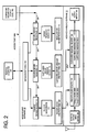
- the application group 674 which includes the management software 10 and the message handling software 12.
- the management software 10 of Figure 6 includes the management menu 108, an interface to the personal computer operating system and browser 676, a TCP/IP web browser based manager 678, a Telenet management interface 680, an SNMP management interface 682, an Internet connect auto-dialer 684, a download management information FTP manager 686, a management code update manager 688, example trigger words 110, example server messages 112, and example server programs 114.
- the message handling software 12 shown in Figure 6 includes the access point to server TCP/IP message interface 690, the wireless packet input buffer 128, the LAN output buffer 130, the trigger word registry 124 and the customized message registry 126.
- the Bluetooth access point device 140 is connected over the landline network 142 and 144 to the service platform server 180, as shown in Figure 1 .
- the service platform server 180 has service offerings that it would like to make available to mobile Bluetooth devices 100 passing within the RF communications range of the Bluetooth access point device 140.
- the Bluetooth access point device 140 periodically sends out Bluetooth inquiry packets 500 on the RF link to any mobile Bluetooth devices 100 within the RF communications range.
- Figure 5A shows the Bluetooth packet structure for an inquiry packet 500 sent by a Bluetooth access point device to the user's device 100.
- the general inquiry access code (GIAC) of the packet 500 is recognized by all Bluetooth devices as an inquiry message.
- any other Bluetooth devices that are in the inquiry scan state such as the user's device 100, are scanning for the receipt of inquiry packets 500. If the user's device 100 in the inquiry scan state receives the inquiry packet 500, it will respond with an inquiry response packet 510 that has sufficient information to enable the Bluetooth access point device to build its inquiry response table of essential information required to make a connection. Any Bluetooth device recognizing inquiry packet 500 can respond.
- FIG. 5B shows the Bluetooth frequency hop synchronization (FHS) packet structure for an inquiry response packet 510 sent by the user's device 100.
- the FHS packet structure for an inquiry response packet 510 sent by the user's device 100 includes the access code field 512, the header which includes the slave member number field 514 in which AM_ADDR is no yet assigned and is set to zero, the type field 516 and the parity field 518. Another the slave member number field 524 also has AM_ADDR set to zero.
- Field 522 contains the user's class-of-device (CoD) information.
- CoD class-of-device
- the FHS packet structure for an inquiry response packet 510 provides essential information about the user's device 100 that enables the Bluetooth access point device to the make a connection to the user's device: Field 520 contains the user's BD_ADDR and field 526 contains the user's current clock value.
- the Bluetooth access point device 140A uses the information provided in the inquiry response packet 510 it has received from the user's device 100 to match with a trigger word in the trigger word registry 124.
- Bluetooth access point device 140A Since Bluetooth access point device 140A has initiated the inquiry, it will be the master device in the new piconet being formed by the two devices. The user's device 100 will become the slave to the Bluetooth access point device 140A.
- the user's device 100 can initiate the connection.
- the user's device 100 can send out an inquiry packet 500 shown in Figure 5A .
- the access point 140 will respond with an inquiry response packet, modified from that shown for packet 510 in Figure 5B , by having the sender's address field 520 contain the access point's address and by having the sender's class of device field 522 contain the access point's CoD value.
- the access point 140 will then have to wait until the user's device 100 responds with a page packet similar to packet 530 of Figure 5C , since the access point 140 will need the information in the page packet in order to match it with a trigger word in the trigger word registry 124.
- the user device's paging packet 530 will contain the user device's address in field 540 and class of device information in field 542.
- the user device's paging packet 530 received by the access point 140 will be buffered in the wireless packet input buffer 128 of Figure 3C . There, its sender's address field 540 of Figure 5C can be matched with address value 266 in the trigger word registry 124 of Figure 3C .
- the address of the device 100 in field 540 can be matched with address values 266 in the trigger word registry 124.
- the class of device of the device 100 in field 542 can be compared with class of device values 268 stored in the trigger word registry 124. If there is a match, then the corresponding customized server message is accessed from the customized server message registry 126 and sent to the server 190 designated in field 294 of the customized server message.
- the invention can also be applied to wireless local area networks employing the IEEE 802.11 Wireless LAN Standard or the HIPERLAN Standard.
- the resulting invention solves the problem of facilitating the preparation of customized messaging between a wireless access point and a variety of service platforms.
Abstract
Description
- The invention disclosed broadly relates to message authoring tools for ubiquitous computing and more particularly relates to improvements in message authoring tools for short range RF technology.
- Short-range mobile wireless devices frequently come within communicating range of stationary wireless devices, known as access points, which are connected to wireline local area networks (LANs) or wide area networks (WANs). The mobile wireless device can form a wireless link with a nearby access point to enable communication with network servers. The network servers can provide services to the mobile wireless devices, which can be customized to the particular access point currently nearest to and communicating with the mobile device. One example is a map display service where regional maps are stored in a network server and local maps characteristic of the neighborhood around an access point, can be downloaded to mobile devices near that access point. This requires that customized messages that are unique to a particular access point, be sent to the network server. As a mobile wireless device moves from one access point to another, the customized messages received by the network server must change to reflect the network identity of the new access point. What is needed in the prior art is a method of facilitating the preparation of customized messaging between an access point and a variety of service platforms.
- Short-range wireless networks include both wireless personal area networks ("PANs") and wireless local area network ("WLANs"). Both of these networks have the common feature of operating in unlicensed portions of the radio spectrum, usually either in the 2.4 GHz Industrial, Scientific, and Medical (ISM) band or the 5 GHz Unlicensed-National Information Infrastructure ("U-NII") band. Wireless personal area networks use low cost, low power wireless devices that have a typical range of ten meters.
- The best-known example of wireless personal area network technology is the Bluetooth Standard, which operates in the 2.4 GHz ISM band. Bluetooth is a short-range radio network, originally intended as a cable replacement. It can be used to create ad hoc networks of up to eight devices operating together. The Bluetooth Special Interest Group, Specification Of The Bluetooth System, , describes the principles of Bluetooth device operation and communication protocols. Bluetooth devices are designed to find other Bluetooth devices within their ten meter radio communications range and to discover what services they offer, using a service discovery protocol (SDP).
- Examples of wireless local area network technology include the IEEE 802.11 Wireless LAN Standard and the HIPERLAN Standard, which operate in the 5 GHz U-NII band. The IEEE 802.11 Wireless LAN Standard is published in three parts as IEEE 802.11-1999; IEEE 802.11a-1999; and IEEE 802.11b-1999, which are available from the IEEE, Inc. web site http://grouper.ieee.org/groups/802/11. An overview of the HIPERLAN Type 2 principles of operation is provided in the Broadband Radio Access Networks (BRAN), HIPERLAN Type 2; System Overview, ETSI TR 101683 VI.I.1 (2000-02). Reference is also directed to
DE-A-19814162 andWO 0133797 - What is needed is a way to facilitate the preparation of customized messaging between a short-range wireless access point and a variety of service platforms to provide the content for those messages.
- To this end, the invention provides a method to facilitate the preparation of customised messaging between a wireless access point and a variety of service platforms as claimed in
claim 1. The invention also includes a system for this purpose as defined in claim 7, and a computer program product according to claim 16. In accordance with the invention, the wireless access point may include a registry of trigger words, each word specifying the particular events that must be detected by the access point upon receiving a packet from a mobile wireless device, in order to invoke the process of sending a corresponding server message to a selected server. The events can also be messages on the local area network connected to the access point, such as LAN access profiles or other network parameters. Message parameters can also be handles to specific services provided by the access point. When the wireless packet is received by the access point, the access point uses the various types of information in the received packet as stimuli to be matched with the trigger words stored in the trigger word registry. The trigger words can also specify LAN parameters. If there is a match, then a customized message corresponding to the matched trigger word is accessed from a customized message registry and sent to the server specified in the message. The selected server may be a server program running on a local personal computer connected to the access point. The selected server may also be a stand alone server connected to the access point over a LAN or it may be a network server located at a web site on the Internet. The selected server can use the information in the customized message to carry out a wide variety of service applications. For example, the selected server can form a query from the information in the customized message, and use it to access a database. The accessed content can then used for a particular service application or it can be returned to the access point for communication to the mobile wireless device. - The wireless access point may include management software to present to the system administrator on a connected personal computer, a management menu of example trigger words and example server messages. The management software may provide an editor to enable the administrator to optionally customize the example trigger words and/or server messages to suit particular applications. When the example trigger words and server messages have been modified into a form satisfactory to the administrator, they are passed to message handling software in the access point, to be loaded into the trigger word registry and the customized message registry, respectively. Updated example trigger words and example server messages can be downloaded to the access point from a web site on the Internet.
- Service platforms running on network servers located at a web site on the Internet, occasionally offer new or updated service applications. The web site may also provide updated example trigger words and updated example server messages, which are available for downloading, to invoke the new or updated service. In accordance with the invention, the management menu of the wireless access point enables the downloading of these new or updated example trigger words and example server messages from the web site. If any modification to is required to the downloaded example trigger words and example server messages, the system administrator can edit them with the management software in the access point.
- The manufacturers of service platform programs that are intended to run on a LAN server or in a local personal computer, will also occasionally offer new or updated service applications. In this case, the new server program itself, is installed onto the local server and new trigger words and server messages are loaded into the access point. Manufacturers can make these new products available from their web sites, or from third party web sites on the Internet. The management menu of the wireless access point may enable the downloading of these new trigger words and server messages and new server programs, along with accompanying server installation programs. If any modification is required to the downloaded new trigger words and new server messages, the system administrator can edit them with the management software in the access point. The management software may also provide an editor to enable the administrator to optionally customize the example server programs so as to be compatible with any modifications to the example server messages. When the example server program has been optionally modified into a form satisfactory to the administrator, it is installed onto the local server by using an installation program accompanying the new server program.
- The example server messages initially presented by the management software to the system administrator on a connected personal computer, can be provided with the data fields in a format that is compatible with the example server program. The system administrator has the option of adopting the example server messages without modification, except to designate the network address of the intended server. If the system administrator elects the option to modify the format of the example server messages, then the management software in the access point provides the ability to make corresponding, optional changes to the example server program in order to accommodate the changed data format of the customized server message, if necessary.
- This configuration according to the invention solves the problem of facilitating the preparation of customized messaging between a wireless access point and a variety of service platforms.
- The invention can be applied to wireless personal area networks employing the Bluetooth Standard, and to wireless local area networks employing the IEEE 802.11 Wireless LAN Standard or the HIPERLAN Standard.
-
Figure 1 is a network diagram according to one embodiment of the present invention showing a plurality ofwireless access points LAN 142 interconnects the access points with thepersonal computer 160 and the Internet 144, which in turn is connected to several content servers. The user'swireless device 100 is shown at a first location near a firstwireless access point 140A and then later at a second location, near a secondwireless access point 140B. -
Figure 1A is a network diagram showing a modification in the topology of the network ofFigure 1 , in which there is a personal computer, such as a laptop computer, directly connected to the access points, and the access points are directly connected to the Internet. -
Figure 1B is a network diagram showing another modification in the topology of the network ofFigure 1 , where the access points are distributed within an office building. TheLAN 142 interconnects the access points with thepersonal computer 160. Several servers are shown connected by means of the LAN to the access points, to provide business-related services when signaled by the access points. -
Figure 1C is a network diagram showing still another modification in the topology of the network ofFigure 1 , where the access points are distributed within a home. TheLAN 142 interconnects the access points with thepersonal computer 160. Several servers are shown connected by means of the LAN to the access points, to provide home-related services when signaled by the access points. -
Figure 2 is a functional block diagram of anaccess point 140A ofFigure 1B , according to one embodiment of the present invention, showing themanagement software partition 10 and the messagehandling software partition 12. -
Figure 2A illustrates the exemplary appearance of themanagement menu 108 of theaccess point 140A, displayed on thepersonal computer 160 ofFigure 1B . Themenu 108 is used during the initial setup of theaccess point 140A to select server programs to be installed in the servers, select trigger words to detect certain types of wireless packets, and to select server messages for sending to the servers in response to satisfying a trigger word. -
Figure 2B illustrates the example server programs partition 114 of themanagement software 10 in theaccess point 140A. Thepartition 114 includes the installation programs for the example server programs. -
Figure 2C illustrates the example trigger words partition 110 of themanagement software 10 in theaccess point 140A. -
Figure 2D illustrates the exampleserver messages partition 112 of themanagement software 10 in theaccess point 140A. -
Figure 3 is an exemplary flow diagram of the processing in an access point during the initial setup period and during the wireless device session period. -
Figure 3A is a functional block diagram of theaccess point 140A ofFigure 1B , illustrating the data flow for the creation of a trigger word and a customized server message for an employee time card application. When a wireless packet is received that satisfies the trigger word, the time card message is sent from the access point to the employee time card program in theserver 190. -
Figure 3B is a functional block diagram of theaccess point 140A ofFigure 1B , illustrating the data flow for the creation of a trigger word and a customized server message for a room lighting control application. When a wireless packet is received that satisfies the trigger word, the light control message is sent from the access point to the room lighting program in theserver 196. -
Figure 3C is a more detailed functional block diagram of theaccess point 140A ofFigure 3B , illustrating the data flow for the triggering of a particular trigger word and corresponding server message in response to the receipt of a particular wireless packet. When a wireless packet is received that satisfies one of the two trigger words in the registry, either the time card message or the light control message is sent from the access point to therespective server -
Figure 3D is a data flow diagram showing theinquiry response packet 510 from the user'sdevice 100 being detected by theaccess point 140A and the access point sending a time card message to thetime card server 190. -
Figure 3E is a data flow diagram showing theinquiry response packet 510 from the user'sdevice 100 being detected by theaccess point 140A and the access point sending a light control message to theroom lighting server 196. -
Figure 3F is a functional block diagram of theaccess point 140C ofFigure 1B , illustrating the data flow for the creation of a trigger word and a customized server message for an area security application. When a wireless packet is received that satisfies the trigger word, the security message is sent from the access point to the area security program in theserver 192. -
Figure 4 illustrates the example appearance of themanagement menu 108 of theaccess point 140A, displayed on thepersonal computer 160 ofFigure 1B . Themenu 108 is shown installing the time card program on theserver 190 and editing the data stored in thedatabase 191. -
Figure 4A is a data flow diagram illustrating the installprogram 171 for the employeetime card program 170. The install program is shown creating the database directory and the program directory in theserver 190 for installation of the employee time card application. -
Figure 4B illustrates the appearance of themanagement menu 108 of theaccess point 140A, displayed on thepersonal computer 160 ofFigure 1B . Themenu 108 is shown editing a trigger word and editing a server message which will be stored in theaccess point 140A for the time card application. -
Figure 4C is a data flow diagram illustrating the employee time card server program operating on the values of the variables provided by the time card message and manipulating the data in the time card database. -
Figure 5A shows the Bluetooth packet structure for aninquiry packet 500 sent by a Bluetooth access point device to the user'sdevice 100. -
Figure 5B shows the Bluetooth frequency hop synchronization (FHS) packet structure for aninquiry response packet 510 sent by the user'sdevice 100. -
Figure 5C shows the wireless frequency hop synchronization (FHS) packet structure for thepaging packet 530 sent by the user'sBluetooth device 100. -
Figure 6 is an architectural diagram of theaccess point 140A, according to one embodiment of the present invention, showing the hardware components and the contents of the memory. -
Figure 1 is a network diagram according to one embodiment of the present invention showing theLAN 142 connected to a plurality ofwireless access points corresponding coverage area wireless device 100 inFigure 1 has amicrobrowser 102, akeypad 104, and anapplication program 106. The user'swireless device 100 is shown at a first location near theaccess point 140A, with the location named "A Street". The figure also shows the user'sdevice 100 at a second location near theaccess point 140B, with the location named "B Street". TheLAN 142 is connected to theInternet 144, which is connected to three content servers, themap content server 180, theadvertising content server 184, and the streetsign content server 186. Connected to themap content server 180 is amap database 182. As the user'swireless device 100 passes within communicating range of theaccess point 140A, communication between thewireless device 100,access point 140A and themap database 182, accesses theportion 120 showing the location named "A Street" of a graphic map from thedatabase 182 and transfers it for display on thebrowser 102 of thedevice 100. Later, as the user'swireless device 100 is within communicating range of thesecond access point 140B, communication between thedevice 100,access point 140B, and themap database 182, accesses theportion 122 showing the location named "B Street" of the map graphic from the database and transfers it for display on thebrowser 102 of thedevice 100. The mechanism for accomplishing this access and transfer of respective portions of the map graphic will be discussed below.Figure 1 also shows thepersonal computer 160 which is used by the system administrator to configure theaccess points Internet 144 is shown connected to aweb site 188 for downloading updated code to the access points.Figure 1A is a network diagram showing a modification in the topology of the network ofFigure 1 , in which thepersonal computers 160 and 160' can be laptop computers which are directly connected to therespective access points Internet 144 without needing a LAN. - Returning to
Figure 1 , eachaccess point management software 10 andmessage handling software 12, as shown in greater detail inFigure 2 . Themessage handling software 12 in each wireless access point includes atrigger word registry 124, each trigger word specifying the particular events that must be detected by the access point upon receiving a wireless packet in theinput buffer 128 from amobile wireless device 100, in order to invoke the process of sending a corresponding server message to a selected server. When the wireless packet is received by the access point, the access point uses the various types of information in the received packet as stimuli to be matched with the trigger words stored in thetrigger word registry 124. If there is a match, then a customized message corresponding to the matched trigger word is accessed from a customized message registry 126 and sent to theserver 180, for example, specified in the message. - The selected server may be a server program, for example the room lighting server program 196' running on a local
personal computer 160 connected to the access point, as shown inFigure 1C. Figure 1C is a network diagram showing a modification in the topology of the network ofFigure 1 , where the access points are distributed within ahome 154. Thehome LAN 142 interconnects theaccess points personal computer 160. Several servers are shown connected by means of the LAN to the access points, to provide home-related services when signaled by the access points. Example servers for home-related services are music server 190' and its database 191', appliances server 192' and its database 193', reminder service server 194' and its database 195', and room lighting server 196' and its database 197'. Each of these servers and databases reside on thehard drive 192 of the homepersonal computer 160 ofFigure 1C . Each of the servers includes an output to the appliance andlighting control line 199, which is connected to the light L1 and appliance A1 in thefoyer coverage area 150A andfront door 156, the light L2 and appliance A2 in the livingroom coverage area 150, the light L3 and appliance A3 in thehallway coverage area 150B, and the light L4 and appliance A4 in thekitchen coverage area 150C. TheLAN 142 is connected by the Internet to theweb site 188, to enable downloading updated code to the access points. - The selected server may also be a stand alone server, for example the employee
time card server 190, connected to the access point over aLAN 142, as shown inFigure 1B. Figure 1B is a network diagram showing a in the topology of the network ofFigure 1 , where the access points are distributed within anoffice building 148. TheLAN 142 interconnects the access points with thepersonal computer 160. Several servers are shown connected by means of the LAN to the access points, to provide business-related services when signaled by the access points. Theoffice LAN 142 interconnects theaccess points personal computer 160. Several servers are shown connected by means of the LAN to the access points, to provide business-related services when signaled by the access points. Example servers for business-related services are employeetime card server 190 and itsdatabase 191,area security server 192 and itsdatabase 193,employee location server 194 and itsdatabase 195, androom lighting server 196 and itsdatabase 197. Each of these servers is a stand alone server. Theroom lighting server 196 includes an output to thelighting control line 198, which is connected to the light L1 in thelobby coverage area 150A andentrance 152, the light L2 in theoffice_1 coverage area 150, the light L3 in theoffice_2 coverage area 150B, and the light L4 in thecashier coverage area 150C. TheLAN 142 is connected by theInternet 144 to theweb site 188, to enable downloading updated code to the access points. - The selected server may also be a network server, for example the
map content server 180, located at a web site on the Internet, as shown inFigure 1 . Any of these selected servers can use the information in the customized message to carry out a wide variety of service applications. For example, the selected server can form a query from the information in the customized message, and use it to access appropriate database. The accessed content can then be used for a particular service application or it can be returned to the access point for communication to themobile wireless device 100. - It is also possible that the message events occur later, e.g., when a LAN access profile is ready (message parameters IP address of the terminal, a port to terminal, Wap Push port to terminal, etc.), Obex link is ready (message param: IP:Port for sending Obex messages to terminal), etc. Message parameters can be handles to specific services provided by the access point (e.g., Handle to Wap Push Port) for the terminal. The communication technique between access point and server can be anything from http messaging to RPC. The management software in access point is applied in defining the event, message, target, and communication protocol. It is not always necessary to state how the message will be received in the target-server, since that is mainly up to target servers. This same messaging can be enhanced to GSM/GPRS/UMTS base stations. When a terminal forms a connection to a GSM link, a message is delivered to particular server.
- Each wireless access point, for example 140A, includes
management software 10 to present to the system administrator on a connectedpersonal computer 160, amanagement menu 108 of example trigger words and example server messages.Figure 2A illustrates the exemplary appearance of themanagement menu 108 of theaccess point 140A, displayed on thepersonal computer 160. Themenu 108 is used during the initial setup of theaccess point 108 to selectexample server programs 114 to be installed in theservers 180, etc., selectexample trigger words 110 to detect certain types of wireless packets, and to selectexample server messages 112 for sending to the servers in response to satisfying a trigger word.Figure 2C illustrates fiveexample trigger words 110 andFigure 2D illustrates the corresponding fiveexample server messages 112. - The
management software 10 provides atrigger word editor 111 to enable the administrator to optionally customize theexample trigger words 110 in a trigger word creation table 230. Aserver message editor 113 is provided to editexample server messages 112 in a server message creation table 232, to suit particular applications. When theexample trigger words 110 andexample server messages 112 have been modified into a form satisfactory to the administrator, they are passed to themessage handling software 12 in the access point, to be loaded overline 256 into thetrigger word registry 124 and overline 278 into the customized message registry 126, respectively. Updated example triggerwords 110 andexample server messages 112 can be downloaded to the access point online 189 from aweb site 188 on the Internet. - Service platforms running on
network servers 180 located at a web site on theInternet 144, occasionally offer new or updated service applications. The web site may also provide updated example trigger words and updated example server messages, which are available for downloading, to invoke the new or updated service. Themanagement menu 108 of the wireless access point, for example 140A, enables the downloading of these new or updatedexample trigger words 110 andexample server messages 112 from the web site. If any modification is required to the downloadedexample trigger words 110 andexample server messages 112, the system administrator can edit them with theeditors management software 10 in the access point. - The manufacturers of service platform programs that are intended to run on a LAN server, for example the employee
time card server 190 ofFigure 1B , or in a localpersonal computer 160, for example the room lighting server program 196' ofFigure 1C , will also occasionally offer new or updated service applications. In this case, the new server program, itself, must be installed onto thelocal server web sites 188, or from third party web sites, on the Internet. Themanagement menu 108 of the wireless access point ofFigure 2 , enables the downloading of thesenew trigger words 110 andserver messages 112 andnew server programs 114 overline 189, along with accompanying server installation programs. If any modification to is required to the downloadednew trigger words 110 andnew server messages 112, the system administrator can edit them with themanagement software 10 in the access point. The management software provides aneditor 115 to enable the administrator to optionally customize theexample server programs 114 to be compatible with any modifications to the example server messages in the server message creation table 232. When theexample server program 114 has been optionally modified into a form satisfactory to the administrator, it is installed by means of the installer 116 into thelocal server Figure 2B illustrates theexample server programs 114 downloaded fromvarious web sites 188. Theexample server programs 114 are shown accompanied by their installation programs. Employee timecard server program 170 is accompanied by itsinstallation program 171. Roomlighting server program 172 is accompanied by itsinstallation program 173. Areasecurity server program 174 is accompanied by itsinstallation program 175. Play music server program 176 is accompanied by itsinstallation program 177. And, reminderservice server program 178 is accompanied by itsinstallation program 179. - Some server programs will ignore empty fields that are otherwise optional in a server message, such as documentation numbers. Where the system administrator elects to modify an example server message by modifying or omitting data in an optional field, no change is necessary to the server program. However, if the system administrator finds it necessary to modify an example server message by omitting data in a required field, by substituting a different type of data in a required field, or by adding a new field, then some modification may be needed to the server program. In accordance with the invention, the
management menu 108 of thewireless access point 140A optionally presents to the system administrator on a connectedpersonal computer 160,example server programs 114 corresponding to theexample server messages 112. Themanagement software 10 provides aneditor 115 to enable the administrator to optionally customize theexample server programs 114 to be compatible with any modifications to theexample server messages 112. When the example server program has been optionally modified into a form satisfactory to the administrator, it is installed into a selectedserver 190, for example, by using an installation program 116 accompanying theexample server program 114. Updatedexample server programs 114 with their accompanying installation programs 116, can be downloaded to theaccess point 140A along with theexample trigger words 110 andexample server messages 112, from aweb site 188 on the Internet. - The
example server messages 112 initially presented by themanagement software 10 to the system administrator on a connectedpersonal computer 160, are provided with the data fields in a format that is compatible with theexample server program 114. The system administrator has the option of adopting theexample server messages 114 without modification, except to designate the network address of the intendedserver 190. If the system administrator elects the option to modify the format of theexample server messages 112, then themanagement software 10 in theaccess point 140A provides the ability to make corresponding, optional changes to theexample server program 114 in order to accommodate the changed data format of the customized server message, if necessary. The resulting server program can then make use of all of the data available in the customized server message to perform the intended application. The customized message will contain the required data in a format that is compatible with the optionally modified server program. Theserver 190 can use this information for an appropriate query of itsdatabase 191 to access the content, under control of the server program. The content is then used in the particular service application provided by the server program or returned to theaccess point 140A for communication to themobile device 100. -
Figure 2A illustrates the exemplary appearance of theuser interface menu 108 of theaccess point 140A, displayed on thepersonal computer 160 ofFigure 1B .Menu 108 is used during the initial setup of the access point 104A, to select server programs to be installed in servers, to select trigger words to detect certain types of wireless packets, and to select server messages for sending to the servers in response to satisfying a trigger word. Themanagement menu 108 has afirst selection 404 to list example trigger words and example customized messages, such as is shown inFigure 2C and Figure 2D , respectively. Theselection 406 is to add, delete, or edit a trigger word or a customized message. Theselection 408 is to load the trigger word and customized message into theaccess point registry 124 and 126, respectively. Theselection 410 lists the example server programs, as is shown inFigure 2B .Selection 412 is to add, delete, or edit a server program or database.Selection 414 is to install a server program or database in a server.Section 416 of themenu 108 ofFigure 2A provides several selections to edit trigger words or customized messages. Selection 418 edits a customized message name or number.Selection 420 edits a destination server for the access point to send a customized message.Selection 422 edits an event trigger word that sends the customized message to the server. Selection 424 edits parameters for customized messages, such as the device address, time of day, etc.Selection 426 edits other options for the trigger word and customized message.Section 428 of themanagement menu 108 ofFigure 2A provides selections for editing a server program and database.Selection 430 edits instructions in the server program andselection 432 edits the database.Selection 434 downloads the updated trigger words, messages and programs from the Internet. In order to provide a secure link between thepersonal computer 160 displaying themanagement menu 108, and any network nodes such as a website, a secure connection is obtained with thesecurity software 436, such as the secure sockets layer. -
Figure 2B illustrates theexample server programs 114 of themanagement software 10 inaccess point 140A. The partition storing theexample server programs 114 also includes the installation programs for the server programs.Figure 2B shows the employeetime card program 170 which is installed in a server by means of theinstallation program 171. Employeetime card program 170 has theoperational steps 340 through 346. When theinstallation program 171 installs the employeetime card program 170 in a server, steps 340 through 346 are executed upon the receipt of a customized message from an access point. Step 340 receives a customized message. Step 341 established the path name c:\tcard. Step 342 looks up the employee in the database using the device address value provided by the customized message. Step 343 looks up the building entrance location in the database using the access point address provided by the customized message. Step 343 gets the time of day. Step 345 prepares a time card record which includes fields for the time, the employee name, and the building entrance. Then step 346 stores the record in the database. - The
room lighting program 172 shown for themanagement software 10 ofFigure 2B , will be installed by theinstallation program 173 in a server.Room lighting program 172 includessteps 350 through 354.Steps 350 through 354 are executed in the server when in receives a customized message. Step 350 receives the customized message. Step 351 establishes the path name c:\lights. Step 352 looks up the lighting circuit in the database using the access point address supplied by the customized message. Step 353 determines if a new connection has been made to awireless device 100 by the access point, then turn on the lights by sending a signal on the lighting control to the lighting circuits. Step 354 determines if an existing connection is broken between awireless device 100 and the access point; then turn off the lights by sending a turn-off signal on the lighting circuit. - The
area security program 174 in themanagement software 10 ofFigure 2B is installed by theinstallation program 175 in a server. Thearea security program 174 hassteps 360 through 364. Thearea security program 174 executes thesteps 360 through 364 upon the receipt of a customized message. Step 360 receives the customized message. Step 361 establishes the pathname c:\secure. Step 362 looks up the authorization in the database using the device address provided by the customized message. Step 363 determines if the device address is authorized and if its, then an entry is made of the security event in the log. Step 364 determines if the device address is not authorized, then the location of the access point is looked up in the database using the access point address supplied by the customized message, and an alarm is sent to the security department. - The play music program 176 in the
management software 10 ofFigure 2B , is installed in a server by means of theinstallation program 177. The play music program 176 includessteps 370 through 375. The play music program 176 executessteps 370 through 375 upon the receipt of a customized message. Step 370 receives the customized message. Step 371 establishes the pathname c:\music. Step 372 looks up a person using the device address received in the customized message. Step 373 accesses the favored music from the database for the person. Step 374 looks up the room audio circuit for the room where the access point is located, using the access point address supplied in the customized message. Step 375 sends the favored music over the audio circuit to the speakers in the room. - The
reminder service program 178 inmanagement software 10 inFigure 2B , is installed in a server by means of theinstallation program 179. Thereminder service program 178 includessteps 380 through 386. Thereminder service program 178 executessteps 380 through 386 upon the receipt of a customized message. Step 380 receives the customized message. Step 381 establishes the pathname c:\remind. Step 382 looks up the person in the database using the device address received in the customized message. Step 383 accesses the reminder list from the database for the person. Step 385 gets the time of day. Step 386 determines if a reminder is now due, then the reminder is sent and a beep sound is also sent to the access point using the access point address, for the purpose of forwarding the reminder and the beep sound in a wireless packet to the wireless device. -
Figure 3 is an exemplary flow diagram of the processing in an access point during theinitial setup period 366 and during thewireless device session 368. Themanagement software 10 includessteps step 387, the access point is connected to a personal computer as shown inFigure 2 , and themanagement menu 108 is displayed, as shown inFigure 2A . The system administrator using themanagement menu 108 will make a selection alongpath Path 388 leads to step 391. To select one of theexample server programs 114 inFigure 2B for the purpose of either installing the server program in a server or optionally editing the program. Step 391 flows to step 392 where the system administrator selects to install the program and the corresponding databases by following the prompts to input data as described inFigures 4 and4A . Instead, if the system administrator choosespath 389 instep 387, the process flows to step 393 where the system administrator selects from themenu 108 one of theexample trigger words 110 shown inFigure 2C for optional editing as shown inFigure 4B . The program then flows to step 394 where the system administrator can select one of theexample server messages 112 shown inFigure 2D and optionally edit the server message as shown inFigure 4B . The process then flows to step 395 where the system administrator then selects to load the trigger word and/or the server message into theaccess point registries 124 and 126, respectively, as shown inFigure 3A . If instead, the system administrator instep 387 selectspath 390, the process directly flows to step 394 to select one of theexample server messages 112 and then the process flows to step 395 to load the server message into the access point registry 126. After the system administrator has successfully selected example server programs, example trigger words and example server messages during theinitial setup period 366, the process flows to the wirelessdevice session period 368. Themessage handling software 12 inFigure 3 includessteps step 396, a wireless packet is received at the access point from a user'sdevice 100. Then instep 397, the fields in the received packet are matched with trigger words and a corresponding message is accessed and sent to the server as shown inFigure 3C andFigure 3D . Then instep 398, the server program is invoked in response to having received the customized message, so as to operate on values of variables provided by the customized message, as shown inFigure 4C . -
Figure 3A is a functional block diagram of theaccess point 140 ofFigure 1B , illustrating the dataflow for the creation of a trigger word in a customized server message for employee time card application. When a wireless packet is received that satisfies the trigger word, the time card message is sent from the access point to the employee time card program in theserver 190.Figure 3A shows the trigger word creation table 330. The trigger word creation table has five fields: thetrigger word number 262, thetrigger signal type 264, thedevice address 266, the class ofdevice 268, andother data 274. A particular trigger word 00001 is shown stored in the trigger word creation table 230. Thetrigger word 0001 specifies a trigger signal type as being either and inquiry packet or a paging packet. The device address can be any device address. The class of device is a cell phone and there is no other data. Thetrigger word 0001 was stored in the trigger word creation table 230 as a result of the system administrator having selected anexample trigger word 110 which flows along path 110' into the trigger word creation table, after which the system administrator edits the trigger word alongpath 111, using themanagement menu 108. After thetrigger word 0001 has been completed to the satisfaction of the system administrator, it is loaded alongpath 256 into thetrigger word registry 124. The customized server message creation table 232 inFigure 3A has the following fields:custom message number 282, the trigger word number 262', thedevice address 284, class ofdevice 286, the geographic coordinatefield 288, theserver path name 292, theserver URL 294 and the accesspoint address field 290. A particular customized message is shown stored in the message creation table 232 inFigure 3A . It has acustom message number 0001 and a trigger word number 00001. It specifies that a device address is to be included in the server message, the class of device is not to be included, the latitude and longitude data is to be included in the geographic coordinate field, that the server path name is specified to be c:\tcard, the server URL is specified as being AD-190, and the access point address is specified as being AP-140A. The customizedmessage 0001 stored in the message creation table 232, is stored there in response to the system administrator having selected the message from theexample server messages 112 over the path 112', using themanagement menu 108. The system administrator has edited the content of the customized server message using editing values overpath 113 with themanagement menu 108. After the customizedserver message 0001 has been completed to the satisfaction of the system administrator, the customized server message is loaded overpath 278 into the customized message registry 126.Figure 3A also shows themessage handling software 12 in theaccess point 140A, which includes the receivepacket buffer 128, thetrigger word registry 124, the customized message registry 126. When a wireless packet is received from the user'swireless device 100, and buffered in the receivepacket buffer 128, the various fields of the packet are compared with corresponding fields in the trigger words stored in thetrigger word registry 124. If a match is found, for example, thetrigger word 0001, then the corresponding customized message is accessed from the customized message registry 126 and output to thelocal area network 142. In this example, the time card message 00001 is accessed and output on theLAN 142 for transmission to the employeetime card server 190, as is specified by the server URL field in the customized message. As was previously described, the employeetime card server 190 includes the employeetime card program 170 which receives the customized message from theaccess point 140A. The employeetime card program 170 then proceeds to execute the steps as previously described. -
Figure 3B is a functional block diagram of theaccess point 140A ofFigure 1B , illustrating the data flow for the creation of a trigger word and a customized server message for a room lighting control application. When a wireless packet is received that satisfies the trigger word, the light control message is sent from the access point to the room lighting program inserver 196. Thetrigger word 0002 is stored in the trigger word creation table 230 ofFigure 3B , and has been accessed from theexample trigger words 110 and edited by the system administrator, after which thetrigger word 0002 is loaded overpath 256 into thetrigger word registry 124. The customizedmessage 0002 has been loaded by the system administrator from a selection from theexample server messages 112 and edited by the system administrator, after which the customizedmessage 0002 is transferred from the message creation table 232 overpath 278 and loaded into the customized message registry 126. When theaccess point 140A receives a wireless packet from the user'sdevice 100 having fields which match one of the trigger words, such astrigger word 0002, in thetrigger word registry 124, the corresponding customized message, such as thelight control message 0002 in the customized message registry 126, is output over thelocal area network 142 to theroom lighting server 196. Theroom lighting server 196 was specified in the server URL field of the customized message. Upon receiving the customized message, theroom lighting server 196 executes theroom lighting program 172, as was previously described. -
Figure 3C is a more detailed functional block diagram of theaccess point 140A ofFigure 3B , illustrating the dataflow for the triggering of a particular trigger word and corresponding server message in response to the receipt of a particular wireless packet. When a wireless packet is received that satisfies one of the two trigger words in the registry, either the time card message or the light control message is sent from the access point to therespective server Figure 3C shows the receivepacket buffer 128 which has received theinquiry response packet 510 from the user'sdevice 100. It is seen thatfield 520 of thepacket 510 includes the address of thedevice 100 which is compared with thefield 266 in thetrigger word registry 124. There it is seen that thetrigger word 0001 specifies that any address will satisfy the word.Trigger word 0002 also specifies that any address will satisfy the word. Theinquiry response packet 510 has thefield 522 which specifies the class of device of theuser wireless device 100. That information is applied to the class ofdevice field 268 of thetrigger word registry 124.Trigger word 0001 specifies that a cell phone must be the class of device.Trigger word 0002 specifies that any class of device will satisfy. In this example, the class of device specified infield 522 of theinquiry response packet 510 is not a cell phone. Therefore, only thetrigger word 0002 is satisfied in thetrigger word registry 124. This signal is then passed as a satisfied trigger signal to the customized message registry 126, where the corresponding trigger word number in field 262' of "0002" is located. The correspondingcustom message number 0002 is then accessed and then output as a customizedevent message 610 to the server. In this example,custom message 0002 is a light control message and therefore thecustom message 0002 is sent to theserver 196 for the lighting control application. -
Figure 3E is a dataflow diagram showing theinquiry response packet 510 from the user'sdevice 100 being detected by theaccess point 140A and the access point sending a light control message to theroom lighting server 196.Figure 3E shows the actual data content of thelight control message 0002 as it is sent by theaccess point 140A to theroom lighting server 196. -
Figure 3D is a dataflow diagram showing theinquiry response packet 510 from the user'sdevice 100 being detected by theaccess point 140A and the access point sending a time card message to thetime card server 190.Figure 3D shows the actual data content of thetime card message 0001, as it is sent by theaccess point 140A to thetime card server 190. -
Figure 3F is a functional block diagram of theaccess point 140C ofFigure 1B , illustrating the dataflow for the creation of a trigger word in a customized server message for an area security application. When a wireless packet is received that satisfies the trigger word, the security message is sent from the access point to the area security program inserver 192. Thetrigger word 0003 is created by the system administrator in the trigger word creation table 230, and the customizedmessage number 0003 is created by the system administrator in the customized server message creation table 232. When the trigger word and the customized message are completed to the satisfaction of the system administrator, they are respectively loaded into thetrigger word registry 124 and the customized message registry 12b. In themessage handling software 12, when a wireless packet is received from thewireless device 100 and loaded into the receivepacket buffer 128, the values in the fields of the packet are compared with the corresponding values in the trigger words of thetrigger word registry 124. If thetrigger word 0003 is satisfied, then a signal is transferred to the customized message registry 126, to access and output thesecurity message 0003 over thelocal area network 142 to thearea security server 192. There, thearea security program 174 is executed in response to receiving the customized message. -
Figure 4 illustrates the example appearance of themanagement menu 108 of theaccess point 140A, displayed on thepersonal computer 160 ofFigure 1B .Menu 108 is shown installing the time card program on theserver 190 and editing the data stored in thedatabase 191. The system administrator selectsstep 414 to install the server program and the database in the server. Themessage 460 is displayed on the menu showing the system administrator's input of the server URL which is AD-190. Then the system administrator makes theselection 432 to edit the database.Message 466 displayed in the menu shows the system administrator's input of data for theemployee database 450 and theentrance database 452. -
Figure 4A is a dataflow diagram illustrating theinstallation program 171 for the employeetime card program 170. The installation program is shown creating the database directory and the program directory in theserver 190 for installation of the employee time card application. Theinstallation program 171 is shown inFigure 4A withsteps 460 through 466. When the installation program is executed on theserver 190,steps 460 through 466 install the employeetime card program 170 and thetime card database 191. Step 460 receives the menu input from the system administrator defining the server URL as AD-190. Step 461 creates the directory c:\tcard on the server. Step 462 creates the sub-directory c:\tcard\pgm. Step 463 stores the time card program 470 in the sub-directory. Then step 464 creates the sub-directory c:\tcard\db. Then step 465 creates sub-directories for theemployee database 450, theentrance database 452, and thetime card database 454. Then step 466 receives the menu input from the system administrator defining data to be stored for theemployee database 450 and theentrance database 452. At the conclusion of theinstallation program 171, both the employeetime card program 170 and thetime card database 191 are installed on theserver 190 and are ready for the receipt of customized messages from theaccess point 140A. -
Figure 4B illustrates the appearance of theuser interface menu 108 of theaccess point 140A, displayed on thepersonal computer 160 ofFigure 1B . Themenu 108 is shown editing a trigger word and editing a server message which will be stored in theaccess point 140A, for the time card application. Themanagement menu 108 shows theselection step 422 to edit the event trigger word that sends the customized message to the server.Figure 4B shows that thetrigger word 0001 is being edited to change the field for class of device from "any" to "cell phone". Thenselection 420 is made to edit the destination server for the access point to send the customized message.Figure 4B shows thetime card message 0001 having theserver URL field 294 edited to change the generic address to the AD-190 address for the destination server. -
Figure 4C is a dataflow diagram illustrating the employee time card server program operating on the values of the variables provided by the time card message and manipulating the data in the time card database.Figure 4C shows thetime card message 0001 which has been received by theserver 190. This initiates the execution of the employeetime card program 170 which passes throughsteps fields 284 of thetime card message 0001 having a value of "dev-100". Step 342 looks up the employee in the database using the device address value of "dev-100", as shown inFigure 4C . The employee name of "Alice" is returned from theemployee database 450 to step 342 of the employeetime card program 170.Program 170 then passes to step 343 which accepts the access point address fromfield 290 of thetime card message 0001, the value of "ap-140a" is passed from thetime card message 0001 to step 343 of theprogram 170, which looks up the building entrance in the database using the access point address. The value of "ap-140a" is passed to thetime card database 191 where thebuilding entrance database 452 is interrogated and the location "front 152" is passed back to step 343 of theprogram 170.Program 170 then continues to flow throughsteps front 152". Then the resulting record is stored in thetime card database 454. -
Figure 5A shows the Bluetooth packet structure for aninquiry packet 500 sent by a Bluetooth access point to the user'sdevice 100.Figure 5B shows the Bluetooth packet structure for an inquiry response packet sent by the user'sdevice 100 back to the access point. -
Figure 5C shows a Bluetooth packet structure for a paging packet sent by the user'sdevice 100 to the access point. -
Figure 6 is an architectural diagram of theaccess point 140A, according to one embodiment of the present invention, showing the hardware components and contents of thememory 652. Thememory 652 is connected by means of the bus 654 to theBluetooth radio 656, theflash memory 658,central processor 660 and the localarea network interface 662. Stored in thememory 652 is thetransport protocol group 664 which includes the logical link control andadaptation protocol 670, the link controller andbaseband 666 and thelink manager 668. Also stored in thememory 652 is themiddleware protocol group 672 which includes RFCOMM, the PPP, IP, UDP and SDP protocols. Also stored in thememory 652 is theapplication group 674 which includes themanagement software 10 and themessage handling software 12. - The
management software 10 ofFigure 6 includes themanagement menu 108, an interface to the personal computer operating system andbrowser 676, a TCP/IP web browser basedmanager 678, aTelenet management interface 680, anSNMP management interface 682, an Internet connect auto-dialer 684, a download managementinformation FTP manager 686, a managementcode update manager 688, example triggerwords 110,example server messages 112, andexample server programs 114. - The
message handling software 12 shown inFigure 6 includes the access point to server TCP/IP message interface 690, the wirelesspacket input buffer 128, theLAN output buffer 130, thetrigger word registry 124 and the customized message registry 126. - The following paragraphs discuss the application of the invention to the Bluetooth standard. In this example, the Bluetooth
access point device 140 is connected over thelandline network service platform server 180, as shown inFigure 1 . Theservice platform server 180 has service offerings that it would like to make available tomobile Bluetooth devices 100 passing within the RF communications range of the Bluetoothaccess point device 140. - The Bluetooth
access point device 140 periodically sends outBluetooth inquiry packets 500 on the RF link to anymobile Bluetooth devices 100 within the RF communications range.Figure 5A shows the Bluetooth packet structure for aninquiry packet 500 sent by a Bluetooth access point device to the user'sdevice 100. The general inquiry access code (GIAC) of thepacket 500 is recognized by all Bluetooth devices as an inquiry message. During the inquiry procedure, any other Bluetooth devices that are in the inquiry scan state, such as the user'sdevice 100, are scanning for the receipt ofinquiry packets 500. If the user'sdevice 100 in the inquiry scan state receives theinquiry packet 500, it will respond with aninquiry response packet 510 that has sufficient information to enable the Bluetooth access point device to build its inquiry response table of essential information required to make a connection. Any Bluetooth device recognizinginquiry packet 500 can respond.Figure 5B shows the Bluetooth frequency hop synchronization (FHS) packet structure for aninquiry response packet 510 sent by the user'sdevice 100. The FHS packet structure for aninquiry response packet 510 sent by the user'sdevice 100 includes theaccess code field 512, the header which includes the slavemember number field 514 in which AM_ADDR is no yet assigned and is set to zero, thetype field 516 and theparity field 518. Another the slavemember number field 524 also has AM_ADDR set to zero.Field 522 contains the user's class-of-device (CoD) information. The FHS packet structure for aninquiry response packet 510, provides essential information about the user'sdevice 100 that enables the Bluetooth access point device to the make a connection to the user's device:Field 520 contains the user's BD_ADDR andfield 526 contains the user's current clock value. The Bluetoothaccess point device 140A uses the information provided in theinquiry response packet 510 it has received from the user'sdevice 100 to match with a trigger word in thetrigger word registry 124. - Since Bluetooth
access point device 140A has initiated the inquiry, it will be the master device in the new piconet being formed by the two devices. The user'sdevice 100 will become the slave to the Bluetoothaccess point device 140A. - Instead of the
access point 140 sending out aninquiry packet 500 and receiving aninquiry response packet 510 from user'sdevice 100 with the user device'saddress 520 and class ofdevice 522 information, the user'sdevice 100, itself, can initiate the connection. The user'sdevice 100 can send out aninquiry packet 500 shown inFigure 5A . Theaccess point 140 will respond with an inquiry response packet, modified from that shown forpacket 510 inFigure 5B , by having the sender'saddress field 520 contain the access point's address and by having the sender's class ofdevice field 522 contain the access point's CoD value. Theaccess point 140 will then have to wait until the user'sdevice 100 responds with a page packet similar topacket 530 ofFigure 5C , since theaccess point 140 will need the information in the page packet in order to match it with a trigger word in thetrigger word registry 124. The user device'spaging packet 530, will contain the user device's address infield 540 and class of device information infield 542. The user device'spaging packet 530 received by theaccess point 140, will be buffered in the wirelesspacket input buffer 128 ofFigure 3C . There, its sender'saddress field 540 ofFigure 5C can be matched withaddress value 266 in thetrigger word registry 124 ofFigure 3C . For example, the address of thedevice 100 infield 540 can be matched withaddress values 266 in thetrigger word registry 124. Also, the class of device of thedevice 100 infield 542, can be compared with class ofdevice values 268 stored in thetrigger word registry 124. If there is a match, then the corresponding customized server message is accessed from the customized server message registry 126 and sent to theserver 190 designated infield 294 of the customized server message. - The invention can also be applied to wireless local area networks employing the IEEE 802.11 Wireless LAN Standard or the HIPERLAN Standard.
- The resulting invention solves the problem of facilitating the preparation of customized messaging between a wireless access point and a variety of service platforms.
- Although a specific embodiment of the invention has been disclosed, it will be understood by those having skill in the art that changes can be made to that specific embodiment without departing from the scope of the invention as defined in the following claims.
Claims (16)
- A method to facilitate the preparation of customized messaging between a wireless access point and a variety of service platforms, comprising:providing a customized message in a wireless access point (140A, 140, 140B, 140C);providing a customized trigger word to accompany the customized message;enabling the access point to detect events specified by the trigger word; andsending the customized message to a content server (180, 184, 186, 188), in response to said detected events.
- The method of claim 1, which further comprises:defining an event trigger word that initiates sending the customized message to the server.
- The method of claim 1 or 2, which further comprises:defining a destination server for the access point to send the customized message.
- The method of any preceding claim which further comprises:defining geographic coordinates of the access point to send the customized message.
- The method of any preceding claim which further comprises:defining said customized message to include the mobile device's address and information to be added by the access point.
- The method of any preceding claim which further comprises:defining parameters for the customized message including geographic coordinates of the access point.
- A system to facilitate the preparation of customized messaging between a wireless access point and a variety of service platforms, comprising:a user interface coupled to an access point (140A, 140, 140B, 140C), for preparing a customized message and trigger word for storage in the access point, to enable the access point to detect events specified by the trigger word;a radio in the access point for receiving a packet from a mobile wireless device (100);a processor in the access point for matching information in the received packet with said trigger word; andsaid processor determining a match and in response, sending the customized message to a server (180, 184, 186, 188).
- The system of claim 7 or method of any one of claim 1 to 6 wherein:said access point and said wireless mobile device are Bluetooth devices.
- The system of claim 7 or method of any one of claims 1 to 6 wherein:said access point and said wireless mobile device are IEEE 802.11 wireless devices.
- The system of claim 7 or method of any one of claims 1 to 6 wherein:said access point and said wireless mobile device are HIPERLAN wireless devices.
- The method of claim 1 further comprising:presenting an example customized message on a user interface coupled to a wireless access point;receiving an editing change to the example customized message from the user interface and storing the edited customized message in the access point;providing a customized trigger word to accompany the edited customized message;enabling the access point to detect events specified by the trigger word; andsending the edited customized message to a server, in response to said detected events.
- The method of claim 1 further comprising:receiving a packet from a mobile wireless device;using information in the received packet as stimuli to be matched with said trigger word; anddetermining a match and in response, sending the customized message to a server.
- The method of claim 12, which further comprises:said customized message being edited in the access point.
- The method of claim 12 or 13, which further comprises:said customized message including the mobile device's address and geographic coordinates of the access point.
- The method of claim 12, 13 or 14 which further comprises:said server using the information in the customized message to access content information.
- A computer program product to facilitate the preparation of customized messaging between a wireless access point and a variety of service platforms, comprising:a computer readable medium;program code in said computer readable medium for preparing a customized message and trigger word at an access point, to enable the access point to detect events specified by the trigger word;program code in said computer readable medium for receiving a packet from a mobile wireless device;program code in said computer readable medium for using information in the received packet as stimuli to be matched with said trigger word; andprogram code in said computer readable medium for determining a match and in response, sending the customized message to a server.
Applications Claiming Priority (3)
| Application Number | Priority Date | Filing Date | Title |
|---|---|---|---|
| US09/985,044 US7555287B1 (en) | 2001-11-01 | 2001-11-01 | Customized messaging between wireless access point and services |
| US985044 | 2001-11-01 | ||
| PCT/IB2002/004437 WO2003038542A2 (en) | 2001-11-01 | 2002-10-25 | Customized messaging between wireless access point and services |
Publications (3)
| Publication Number | Publication Date |
|---|---|
| EP1440588A2 EP1440588A2 (en) | 2004-07-28 |
| EP1440588A4 EP1440588A4 (en) | 2007-04-04 |
| EP1440588B1 true EP1440588B1 (en) | 2008-07-16 |
Family
ID=25531138
Family Applications (1)
| Application Number | Title | Priority Date | Filing Date |
|---|---|---|---|
| EP02802341A Expired - Lifetime EP1440588B1 (en) | 2001-11-01 | 2002-10-25 | Customized messaging between wireless access point and services |
Country Status (8)
| Country | Link |
|---|---|
| US (1) | US7555287B1 (en) |
| EP (1) | EP1440588B1 (en) |
| KR (1) | KR100700688B1 (en) |
| CN (1) | CN1326406C (en) |
| AT (1) | ATE401751T1 (en) |
| AU (1) | AU2002334343A1 (en) |
| DE (1) | DE60227689D1 (en) |
| WO (1) | WO2003038542A2 (en) |
Families Citing this family (48)
| Publication number | Priority date | Publication date | Assignee | Title |
|---|---|---|---|---|
| US10915296B2 (en) | 2000-11-01 | 2021-02-09 | Flexiworld Technologies, Inc. | Information apparatus that includes a touch sensitive screen interface for managing or replying to e-mails |
| US10860290B2 (en) | 2000-11-01 | 2020-12-08 | Flexiworld Technologies, Inc. | Mobile information apparatuses that include a digital camera, a touch sensitive screen interface, support for voice activated commands, and a wireless communication chip or chipset supporting IEEE 802.11 |
| US20020059415A1 (en) * | 2000-11-01 | 2002-05-16 | Chang William Ho | Manager for device-to-device pervasive digital output |
| US11204729B2 (en) | 2000-11-01 | 2021-12-21 | Flexiworld Technologies, Inc. | Internet based digital content services for pervasively providing protected digital content to smart devices based on having subscribed to the digital content service |
| WO2002042896A1 (en) | 2000-11-20 | 2002-05-30 | Flexiworld Technologies, Inc. | tOBILE AND PERVASIVE OUTPUT COMPONENTS |
| US20020097416A1 (en) | 2001-01-19 | 2002-07-25 | Chang William Ho | Output controller processor for universal data output |
| US7340214B1 (en) * | 2002-02-13 | 2008-03-04 | Nokia Corporation | Short-range wireless system and method for multimedia tags |
| US20050138172A1 (en) * | 2003-12-23 | 2005-06-23 | International Business Machines Corporation | Use of access points for autonomic determination of available resources |
| US8364081B1 (en) | 2004-07-12 | 2013-01-29 | Stragent, Llc | System, method, and computer program product for using a cellular phone as an interface for a VoIP-equipped computer |
| US9185618B1 (en) | 2005-12-05 | 2015-11-10 | Meru Networks | Seamless roaming in wireless networks |
| US9730125B2 (en) | 2005-12-05 | 2017-08-08 | Fortinet, Inc. | Aggregated beacons for per station control of multiple stations across multiple access points in a wireless communication network |
| US9025581B2 (en) | 2005-12-05 | 2015-05-05 | Meru Networks | Hybrid virtual cell and virtual port wireless network architecture |
| US8160664B1 (en) | 2005-12-05 | 2012-04-17 | Meru Networks | Omni-directional antenna supporting simultaneous transmission and reception of multiple radios with narrow frequency separation |
| US8472359B2 (en) | 2009-12-09 | 2013-06-25 | Meru Networks | Seamless mobility in wireless networks |
| US9215745B1 (en) | 2005-12-09 | 2015-12-15 | Meru Networks | Network-based control of stations in a wireless communication network |
| US9215754B2 (en) | 2007-03-07 | 2015-12-15 | Menu Networks | Wi-Fi virtual port uplink medium access control |
| US9794801B1 (en) | 2005-12-05 | 2017-10-17 | Fortinet, Inc. | Multicast and unicast messages in a virtual cell communication system |
| US9142873B1 (en) | 2005-12-05 | 2015-09-22 | Meru Networks | Wireless communication antennae for concurrent communication in an access point |
| US8064601B1 (en) | 2006-03-31 | 2011-11-22 | Meru Networks | Security in wireless communication systems |
| US20070290832A1 (en) * | 2006-06-16 | 2007-12-20 | Fmr Corp. | Invoking actionable alerts |
| US8532628B2 (en) * | 2006-06-16 | 2013-09-10 | Fmr Llc | Registering actionable alerts |
| US7827138B2 (en) * | 2006-10-02 | 2010-11-02 | Salesforce.Com, Inc. | Method and system for synchronizing a server and an on-demand database service |
| US8255374B2 (en) * | 2006-10-02 | 2012-08-28 | Salesforce.Com, Inc. | Method and system for selecting amongst a plurality of processes to send a message |
| CN101330393B (en) * | 2007-06-19 | 2012-10-17 | 华为技术有限公司 | Method, terminal and network for providing service customization and customization service |
| US7894436B1 (en) | 2007-09-07 | 2011-02-22 | Meru Networks | Flow inspection |
| US8112407B2 (en) * | 2007-10-24 | 2012-02-07 | The Invention Science Fund I, Llc | Selecting a second content based on a user's reaction to a first content |
| US20090112695A1 (en) * | 2007-10-24 | 2009-04-30 | Searete Llc, A Limited Liability Corporation Of The State Of Delaware | Physiological response based targeted advertising |
| US8234262B2 (en) * | 2007-10-24 | 2012-07-31 | The Invention Science Fund I, Llc | Method of selecting a second content based on a user's reaction to a first content of at least two instances of displayed content |
| US9582805B2 (en) * | 2007-10-24 | 2017-02-28 | Invention Science Fund I, Llc | Returning a personalized advertisement |
| US20090112849A1 (en) * | 2007-10-24 | 2009-04-30 | Searete Llc | Selecting a second content based on a user's reaction to a first content of at least two instances of displayed content |
| US20090112696A1 (en) * | 2007-10-24 | 2009-04-30 | Jung Edward K Y | Method of space-available advertising in a mobile device |
| US20090112693A1 (en) * | 2007-10-24 | 2009-04-30 | Jung Edward K Y | Providing personalized advertising |
| US8126867B2 (en) * | 2007-10-24 | 2012-02-28 | The Invention Science Fund I, Llc | Returning a second content based on a user's reaction to a first content |
| US9513699B2 (en) * | 2007-10-24 | 2016-12-06 | Invention Science Fund I, LL | Method of selecting a second content based on a user's reaction to a first content |
| US20090112694A1 (en) * | 2007-10-24 | 2009-04-30 | Searete Llc, A Limited Liability Corporation Of The State Of Delaware | Targeted-advertising based on a sensed physiological response by a person to a general advertisement |
| US20090112697A1 (en) * | 2007-10-30 | 2009-04-30 | Searete Llc, A Limited Liability Corporation Of The State Of Delaware | Providing personalized advertising |
| US8825792B1 (en) | 2008-03-11 | 2014-09-02 | United Services Automobile Association (Usaa) | Systems and methods for online brand continuity |
| US8966003B2 (en) * | 2008-09-19 | 2015-02-24 | Limelight Networks, Inc. | Content delivery network stream server vignette distribution |
| AU2010202034B1 (en) | 2010-04-07 | 2010-12-23 | Limelight Networks, Inc. | Partial object distribution in content delivery network |
| AU2010276462B1 (en) | 2010-12-27 | 2012-01-12 | Limelight Networks, Inc. | Partial object caching |
| US8495428B2 (en) | 2009-06-30 | 2013-07-23 | International Business Machines Corporation | Quality of service management of end user devices in an end user network |
| US9197482B1 (en) | 2009-12-29 | 2015-11-24 | Meru Networks | Optimizing quality of service in wireless networks |
| US8941539B1 (en) | 2011-02-23 | 2015-01-27 | Meru Networks | Dual-stack dual-band MIMO antenna |
| US20120259927A1 (en) * | 2011-04-05 | 2012-10-11 | Lockhart Kendall G | System and Method for Processing Interactive Multimedia Messages |
| CA2918062A1 (en) * | 2012-07-12 | 2014-01-16 | Md Databank Corp | Secure storage system and uses thereof |
| US9021431B2 (en) | 2013-01-07 | 2015-04-28 | Abb Inc. | System and method for developing, deploying and implementing power system computer applications |
| WO2017091744A1 (en) * | 2015-11-25 | 2017-06-01 | Lantronix, Inc. | Bridging with web manager access |
| US10839802B2 (en) * | 2018-12-14 | 2020-11-17 | Motorola Mobility Llc | Personalized phrase spotting during automatic speech recognition |
Family Cites Families (110)
| Publication number | Priority date | Publication date | Assignee | Title |
|---|---|---|---|---|
| US6167278A (en) | 1986-10-22 | 2000-12-26 | Nilssen; Ole K. | Combination cordless-cellular telephone system |
| CA2107820A1 (en) | 1992-10-16 | 1994-04-17 | Keith Daniel O'neill | Low-power wireless system for telephone services |
| US5668878A (en) | 1994-02-28 | 1997-09-16 | Brands; Stefanus Alfonsus | Secure cryptographic methods for electronic transfer of information |
| US5606617A (en) | 1994-10-14 | 1997-02-25 | Brands; Stefanus A. | Secret-key certificates |
| WO1996031034A1 (en) | 1995-03-27 | 1996-10-03 | Stefanus Alfonsus Brands | System for ensuring that the blinding of secret-key certificates is restricted, even if the issuing protocol is performed in parallel mode |
| US5749081A (en) | 1995-04-06 | 1998-05-05 | Firefly Network, Inc. | System and method for recommending items to a user |
| US6430413B1 (en) | 1995-05-31 | 2002-08-06 | Siemens Aktiengesellschaft | Mobile radio receiver for cellular radio telecommunications systems |
| US5835061A (en) * | 1995-06-06 | 1998-11-10 | Wayport, Inc. | Method and apparatus for geographic-based communications service |
| US6049777A (en) | 1995-06-30 | 2000-04-11 | Microsoft Corporation | Computer-implemented collaborative filtering based method for recommending an item to a user |
| US6092049A (en) | 1995-06-30 | 2000-07-18 | Microsoft Corporation | Method and apparatus for efficiently recommending items using automated collaborative filtering and feature-guided automated collaborative filtering |
| US6041311A (en) | 1995-06-30 | 2000-03-21 | Microsoft Corporation | Method and apparatus for item recommendation using automated collaborative filtering |
| US5903832A (en) | 1995-12-21 | 1999-05-11 | Nokia Mobile Phones Llimited | Mobile terminal having enhanced system selection capability |
| US6119101A (en) | 1996-01-17 | 2000-09-12 | Personal Agents, Inc. | Intelligent agents for electronic commerce |
| DE19630399C1 (en) | 1996-07-26 | 1997-10-16 | Siemens Ag | Connect path steering method for public mobile communication network |
| FI103546B (en) | 1996-09-16 | 1999-07-15 | Nokia Telecommunications Oy | Data service in a mobile telephone network |
| US6195657B1 (en) | 1996-09-26 | 2001-02-27 | Imana, Inc. | Software, method and apparatus for efficient categorization and recommendation of subjects according to multidimensional semantics |
| US6108493A (en) | 1996-10-08 | 2000-08-22 | Regents Of The University Of Minnesota | System, method, and article of manufacture for utilizing implicit ratings in collaborative filters |
| US6044062A (en) | 1996-12-06 | 2000-03-28 | Communique, Llc | Wireless network system and method for providing same |
| FI980351A (en) * | 1997-02-19 | 1998-08-20 | Nokia Telecommunications Oy | Cellular radio access network and location update in a wireless communication system |
| US6134445A (en) | 1997-07-24 | 2000-10-17 | Lucent Technologies, Inc. | Wireless terminal adapted for measuring signal propagation characteristics |
| US6243451B1 (en) * | 1997-10-09 | 2001-06-05 | Alcatel Usa Sourcing, L.P. | Service management access point |
| US6236768B1 (en) | 1997-10-14 | 2001-05-22 | Massachusetts Institute Of Technology | Method and apparatus for automated, context-dependent retrieval of information |
| US6421707B1 (en) | 1998-02-13 | 2002-07-16 | Lucent Technologies Inc. | Wireless multi-media messaging communications method and apparatus |
| JP3634614B2 (en) | 1998-02-17 | 2005-03-30 | 富士通株式会社 | Communication system and communication apparatus |
| US6065012A (en) | 1998-02-27 | 2000-05-16 | Microsoft Corporation | System and method for displaying and manipulating user-relevant data |
| US6064980A (en) | 1998-03-17 | 2000-05-16 | Amazon.Com, Inc. | System and methods for collaborative recommendations |
| DE19814162A1 (en) * | 1998-03-30 | 1999-10-07 | Siemens Ag | Method and service switching unit for requesting information on incoming calls directed to a subscriber of a communication network |
| US6055227A (en) * | 1998-04-02 | 2000-04-25 | Lucent Technologies, Inc. | Method for creating and modifying similar and dissimilar databases for use in network configurations for telecommunication systems |
| US6173316B1 (en) | 1998-04-08 | 2001-01-09 | Geoworks Corporation | Wireless communication device with markup language based man-machine interface |
| JPH11298930A (en) | 1998-04-16 | 1999-10-29 | Nec Corp | Private branch of exchange providing hand-over function for phs |
| US6138158A (en) | 1998-04-30 | 2000-10-24 | Phone.Com, Inc. | Method and system for pushing and pulling data using wideband and narrowband transport systems |
| EP1080415B1 (en) | 1998-05-21 | 2017-01-18 | Equifax Inc. | System and method for authentication of network users |
| US6006200A (en) | 1998-05-22 | 1999-12-21 | International Business Machines Corporation | Method of providing an identifier for transactions |
| US6182050B1 (en) | 1998-05-28 | 2001-01-30 | Acceleration Software International Corporation | Advertisements distributed on-line using target criteria screening with method for maintaining end user privacy |
| US6438585B2 (en) | 1998-05-29 | 2002-08-20 | Research In Motion Limited | System and method for redirecting message attachments between a host system and a mobile data communication device |
| US6138159A (en) | 1998-06-11 | 2000-10-24 | Phaal; Peter | Load direction mechanism |
| JP3581251B2 (en) | 1998-06-16 | 2004-10-27 | 株式会社東芝 | Communication system, data packet transfer method, router device, and packet relay device |
| US6519453B1 (en) | 1998-07-01 | 2003-02-11 | Canon Kabushiki Kaisha | Communication apparatus |
| JP3358555B2 (en) | 1998-08-27 | 2002-12-24 | 日本電気株式会社 | Path setting method in mobile packet communication |
| US6154783A (en) | 1998-09-18 | 2000-11-28 | Tacit Knowledge Systems | Method and apparatus for addressing an electronic document for transmission over a network |
| US6253202B1 (en) | 1998-09-18 | 2001-06-26 | Tacit Knowledge Systems, Inc. | Method, system and apparatus for authorizing access by a first user to a knowledge profile of a second user responsive to an access request from the first user |
| JP3239859B2 (en) * | 1998-09-24 | 2001-12-17 | 日本電気株式会社 | Mobile communication system and communication method thereof |
| US6275824B1 (en) | 1998-10-02 | 2001-08-14 | Ncr Corporation | System and method for managing data privacy in a database management system |
| US6253203B1 (en) | 1998-10-02 | 2001-06-26 | Ncr Corporation | Privacy-enhanced database |
| AU1125300A (en) | 1998-10-22 | 2000-05-08 | University Of Maryland | Method and system for providing location dependent and personal identification information to a public safety answering point |
| US6023241A (en) | 1998-11-13 | 2000-02-08 | Intel Corporation | Digital multimedia navigation player/recorder |
| US6195651B1 (en) | 1998-11-19 | 2001-02-27 | Andersen Consulting Properties Bv | System, method and article of manufacture for a tuned user application experience |
| US6493550B1 (en) | 1998-11-20 | 2002-12-10 | Ericsson Inc. | System proximity detection by mobile stations |
| US6243581B1 (en) | 1998-12-11 | 2001-06-05 | Nortel Networks Limited | Method and system for seamless roaming between wireless communication networks with a mobile terminal |
| US6842877B2 (en) | 1998-12-18 | 2005-01-11 | Tangis Corporation | Contextual responses based on automated learning techniques |
| US6199099B1 (en) | 1999-03-05 | 2001-03-06 | Ac Properties B.V. | System, method and article of manufacture for a mobile communication network utilizing a distributed communication network |
| US6414955B1 (en) | 1999-03-23 | 2002-07-02 | Innovative Technology Licensing, Llc | Distributed topology learning method and apparatus for wireless networks |
| US6604140B1 (en) | 1999-03-31 | 2003-08-05 | International Business Machines Corporation | Service framework for computing devices |
| US6389284B1 (en) * | 1999-05-27 | 2002-05-14 | Qwest Communications International, Inc. | System and method for controlling wireless network access |
| US6721542B1 (en) | 1999-05-28 | 2004-04-13 | Nokia Corporation | System for location specific, automatic mobile station behavior control |
| US6539225B1 (en) | 1999-06-21 | 2003-03-25 | Lucent Technologies Inc. | Seamless data network telecommunication service during mobile wireless call handoff |
| US6549625B1 (en) | 1999-06-24 | 2003-04-15 | Nokia Corporation | Method and system for connecting a mobile terminal to a database |
| US6477373B1 (en) | 1999-08-10 | 2002-11-05 | Research Foundation Of State University Of New York | Method and apparatus to maintain connectivity for mobile terminals in wireless and cellular communications systems |
| US6554707B1 (en) | 1999-09-24 | 2003-04-29 | Nokia Corporation | Interactive voice, wireless game system using predictive command input |
| US6527641B1 (en) | 1999-09-24 | 2003-03-04 | Nokia Corporation | System for profiling mobile station activity in a predictive command wireless game system |
| EP1087323A1 (en) | 1999-09-24 | 2001-03-28 | Nokia Corporation | A wireless system for interacting with a virtual space |
| US6571221B1 (en) * | 1999-11-03 | 2003-05-27 | Wayport, Inc. | Network communication service with an improved subscriber model using digital certificates |
| GB9927597D0 (en) * | 1999-11-22 | 2000-01-19 | Nokia Networks Oy | Improving charging efficiency |
| US6601093B1 (en) | 1999-12-01 | 2003-07-29 | Ibm Corporation | Address resolution in ad-hoc networking |
| ATE471647T1 (en) | 1999-12-06 | 2010-07-15 | Ericsson Telefon Ab L M | INTELLIGENT PRODUCTION OF PICONETS |
| US6445921B1 (en) | 1999-12-20 | 2002-09-03 | Koninklijke Philips Electronics N.V. | Call re-establishment for a dual mode telephone |
| GB2357668A (en) | 1999-12-24 | 2001-06-27 | Nokia Mobile Phones Ltd | Mobile telephone interface allowing user-specification of message delivery conditions |
| US6255800B1 (en) | 2000-01-03 | 2001-07-03 | Texas Instruments Incorporated | Bluetooth enabled mobile device charging cradle and system |
| NO316627B1 (en) | 2000-01-12 | 2004-03-15 | Ericsson Telefon Ab L M | Private cordless WAP system |
| US6680919B1 (en) | 2000-02-04 | 2004-01-20 | Nokia Corporation | Downloading of maps and location specific configuration information to GPS-capable mobile communication terminal |
| US6510381B2 (en) | 2000-02-11 | 2003-01-21 | Thomas L. Grounds | Vehicle mounted device and a method for transmitting vehicle position data to a network-based server |
| US6862276B1 (en) | 2000-03-30 | 2005-03-01 | Qualcomm Incorporated | Method and apparatus for a mobile station application to receive and transmit raw packetized data |
| US6430395B2 (en) | 2000-04-07 | 2002-08-06 | Commil Ltd. | Wireless private branch exchange (WPBX) and communicating between mobile units and base stations |
| US6920319B2 (en) * | 2000-05-05 | 2005-07-19 | Axis Ab | Method and apparatus for a mobile access system delivering location based information and services |
| US6917960B1 (en) | 2000-05-05 | 2005-07-12 | Jibe Networks | Intelligent content precaching |
| KR20030047885A (en) | 2000-05-05 | 2003-06-18 | 가부시끼가이샤 메가 칩스 | System and method for obtaining and storing information for deferred browsing |
| US6862594B1 (en) | 2000-05-09 | 2005-03-01 | Sun Microsystems, Inc. | Method and apparatus to discover services using flexible search criteria |
| CN1393083A (en) | 2000-05-19 | 2003-01-22 | 索尼株式会社 | Network conferencing system, equipment management method and data presentation method |
| US6546263B1 (en) | 2000-06-12 | 2003-04-08 | Ericsson Inc. | Apparatus and method for compact icon display |
| AU2001276992A1 (en) * | 2000-07-20 | 2002-02-05 | Aeptec Microsystems, Inc. | Method, system, and protocol for location-aware mobile devices |
| WO2002010984A2 (en) | 2000-07-21 | 2002-02-07 | Triplehop Technologies, Inc. | System and method for obtaining user preferences and providing user recommendations for unseen physical and information goods and services |
| CA2416253A1 (en) | 2000-07-28 | 2002-02-07 | American Calcar Inc. | Technique for effective organization and communication of information |
| WO2002011396A2 (en) | 2000-08-01 | 2002-02-07 | Hrl Laboratories, Llc | Apparatus and method for context-sensitive dynamic information service |
| US6704024B2 (en) | 2000-08-07 | 2004-03-09 | Zframe, Inc. | Visual content browsing using rasterized representations |
| JP2002057698A (en) | 2000-08-09 | 2002-02-22 | Fujitsu Ltd | Packet data processor |
| US6542740B1 (en) | 2000-10-24 | 2003-04-01 | Litepoint, Corp. | System, method and article of manufacture for utilizing a wireless link in an interface roaming network framework |
| US20020059415A1 (en) | 2000-11-01 | 2002-05-16 | Chang William Ho | Manager for device-to-device pervasive digital output |
| US6714519B2 (en) | 2000-11-03 | 2004-03-30 | Vocaltec Communications Limited | Communications availability |
| US20020065881A1 (en) | 2000-11-29 | 2002-05-30 | Tapio Mansikkaniemi | Wireless family bulletin board |
| US20020116458A1 (en) | 2000-12-14 | 2002-08-22 | Jonathan Bricklin | Web-based dating service |
| US7164885B2 (en) | 2000-12-18 | 2007-01-16 | Telefonaktiebolaget L M Ericsson (Publ) | Method and apparatus for selective service access |
| WO2002051063A1 (en) | 2000-12-21 | 2002-06-27 | Digimarc Corporation | Methods, apparatus and programs for generating and utilizing content signatures |
| US6658325B2 (en) | 2001-01-16 | 2003-12-02 | Stephen Eliot Zweig | Mobile robotic with web server and digital radio links |
| US20020094778A1 (en) | 2001-01-18 | 2002-07-18 | Cannon Joseph M. | Bluetooth connection quality indicator |
| US20020198882A1 (en) | 2001-03-29 | 2002-12-26 | Linden Gregory D. | Content personalization based on actions performed during a current browsing session |
| US6961545B2 (en) * | 2001-04-09 | 2005-11-01 | Atheros Communications, Inc. | Method and system for providing antenna diversity |
| US7296042B2 (en) | 2001-04-20 | 2007-11-13 | Palo Alto Research Center Incorporated | System and method for enabling communication among arbitrary components |
| US6931429B2 (en) | 2001-04-27 | 2005-08-16 | Left Gate Holdings, Inc. | Adaptable wireless proximity networking |
| US6925481B2 (en) | 2001-05-03 | 2005-08-02 | Symantec Corp. | Technique for enabling remote data access and manipulation from a pervasive device |
| JP4658374B2 (en) | 2001-05-10 | 2011-03-23 | 株式会社リコー | Wireless communication method and master terminal thereof |
| US6678516B2 (en) * | 2001-05-21 | 2004-01-13 | Nokia Corporation | Method, system, and apparatus for providing services in a privacy enabled mobile and Ubicom environment |
| US20030013459A1 (en) | 2001-07-10 | 2003-01-16 | Koninklijke Philips Electronics N.V. | Method and system for location based recordal of user activity |
| ATE365337T1 (en) * | 2001-09-05 | 2007-07-15 | Newbury Networks Inc | POSITION DETECTION AND LOCATION TRACKING IN A WIRELESS NETWORK |
| US20030115038A1 (en) | 2001-12-18 | 2003-06-19 | Roy Want | Method and device for emulating electronic apparatus |
| US7065382B2 (en) | 2001-12-20 | 2006-06-20 | Nokia Corporation | Wireless terminal having a scanner for issuing an alert when within the range of a target wireless terminal |
| US7133663B2 (en) | 2001-12-20 | 2006-11-07 | Accenture Global Services, Gmbh | Determining the context of surroundings |
| US7591020B2 (en) | 2002-01-18 | 2009-09-15 | Palm, Inc. | Location based security modification system and method |
| US7552265B2 (en) | 2002-01-23 | 2009-06-23 | Xerox Corporation | System and method for providing context information |
| JP2003271630A (en) | 2002-03-15 | 2003-09-26 | Yamaha Corp | Information retrieval method, program and device |
| JP3697437B2 (en) | 2002-10-10 | 2005-09-21 | 株式会社東芝 | Network system and network system construction method |
-
2001
- 2001-11-01 US US09/985,044 patent/US7555287B1/en not_active Expired - Lifetime
-
2002
- 2002-10-25 AU AU2002334343A patent/AU2002334343A1/en not_active Abandoned
- 2002-10-25 CN CNB028216466A patent/CN1326406C/en not_active Expired - Fee Related
- 2002-10-25 EP EP02802341A patent/EP1440588B1/en not_active Expired - Lifetime
- 2002-10-25 DE DE60227689T patent/DE60227689D1/en not_active Expired - Lifetime
- 2002-10-25 AT AT02802341T patent/ATE401751T1/en not_active IP Right Cessation
- 2002-10-25 WO PCT/IB2002/004437 patent/WO2003038542A2/en active IP Right Grant
- 2002-10-25 KR KR1020047006509A patent/KR100700688B1/en active IP Right Grant
Also Published As
| Publication number | Publication date |
|---|---|
| ATE401751T1 (en) | 2008-08-15 |
| CN1326406C (en) | 2007-07-11 |
| WO2003038542A3 (en) | 2003-10-02 |
| AU2002334343A1 (en) | 2003-05-12 |
| DE60227689D1 (en) | 2008-08-28 |
| WO2003038542A2 (en) | 2003-05-08 |
| EP1440588A4 (en) | 2007-04-04 |
| US7555287B1 (en) | 2009-06-30 |
| CN1695388A (en) | 2005-11-09 |
| KR20040058258A (en) | 2004-07-03 |
| EP1440588A2 (en) | 2004-07-28 |
| KR100700688B1 (en) | 2007-03-27 |
Similar Documents
| Publication | Publication Date | Title |
|---|---|---|
| EP1440588B1 (en) | Customized messaging between wireless access point and services | |
| US7492777B2 (en) | Device detection and service discovery system and method for a mobile ad hoc communications network | |
| JP4095599B2 (en) | Demand-based provisioning for mobile communication devices | |
| US6628938B1 (en) | Wireless system, a method of selecting an application while receiving application specific messages and user location method using user location awareness | |
| RU2390952C2 (en) | Determination of control units in device control system | |
| US20030212684A1 (en) | System and method for adapting preferences based on device location or network topology | |
| JP4563425B2 (en) | Device detection and service discovery system and method for mobile ad hoc communication networks | |
| KR20070086208A (en) | Method and apparatus for carrier customization in communication systems | |
| EP1473873A2 (en) | Device management | |
| EP1374493A2 (en) | Beacon update mechanism | |
| WO2002082725A1 (en) | Framework for a dynamic management system | |
| JP2008515310A (en) | Method and system for contextually starting a mobile terminal synchronization service in an enterprise environment | |
| JP2007215235A (en) | Demand-based provisioning for mobile communication device | |
| CN100531226C (en) | Wireless application protocol pre-configuration guiding method | |
| KR100378821B1 (en) | Software download method and apparatus using radio communication | |
| JP2005151397A (en) | Relay base station apparatus, radio communication system and method, radio communication program | |
| Amanquah et al. | Deploying a middleware architecture for next generation mobile systems |
Legal Events
| Date | Code | Title | Description |
|---|---|---|---|
| PUAI | Public reference made under article 153(3) epc to a published international application that has entered the european phase |
Free format text: ORIGINAL CODE: 0009012 |
|
| 17P | Request for examination filed |
Effective date: 20040403 |
|
| AK | Designated contracting states |
Kind code of ref document: A2 Designated state(s): AT BE BG CH CY CZ DE DK EE ES FI FR GB GR IE IT LI LU MC NL PT SE SK TR |
|
| AX | Request for extension of the european patent |
Extension state: AL LT LV MK RO SI |
|
| A4 | Supplementary search report drawn up and despatched |
Effective date: 20070305 |
|
| RIC1 | Information provided on ipc code assigned before grant |
Ipc: H04Q 7/38 20060101ALN20070227BHEP Ipc: H04Q 7/24 20060101AFI20070227BHEP |
|
| 17Q | First examination report despatched |
Effective date: 20070511 |
|
| GRAP | Despatch of communication of intention to grant a patent |
Free format text: ORIGINAL CODE: EPIDOSNIGR1 |
|
| GRAS | Grant fee paid |
Free format text: ORIGINAL CODE: EPIDOSNIGR3 |
|
| GRAA | (expected) grant |
Free format text: ORIGINAL CODE: 0009210 |
|
| AK | Designated contracting states |
Kind code of ref document: B1 Designated state(s): AT BE BG CH CY CZ DE DK EE ES FI FR GB GR IE IT LI LU MC NL PT SE SK TR |
|
| REG | Reference to a national code |
Ref country code: GB Ref legal event code: FG4D |
|
| REG | Reference to a national code |
Ref country code: CH Ref legal event code: EP |
|
| REF | Corresponds to: |
Ref document number: 60227689 Country of ref document: DE Date of ref document: 20080828 Kind code of ref document: P |
|
| REG | Reference to a national code |
Ref country code: IE Ref legal event code: FG4D |
|
| NLV1 | Nl: lapsed or annulled due to failure to fulfill the requirements of art. 29p and 29m of the patents act | ||
| PG25 | Lapsed in a contracting state [announced via postgrant information from national office to epo] |
Ref country code: PT Free format text: LAPSE BECAUSE OF FAILURE TO SUBMIT A TRANSLATION OF THE DESCRIPTION OR TO PAY THE FEE WITHIN THE PRESCRIBED TIME-LIMIT Effective date: 20081216 Ref country code: NL Free format text: LAPSE BECAUSE OF FAILURE TO SUBMIT A TRANSLATION OF THE DESCRIPTION OR TO PAY THE FEE WITHIN THE PRESCRIBED TIME-LIMIT Effective date: 20080716 Ref country code: ES Free format text: LAPSE BECAUSE OF FAILURE TO SUBMIT A TRANSLATION OF THE DESCRIPTION OR TO PAY THE FEE WITHIN THE PRESCRIBED TIME-LIMIT Effective date: 20081027 |
|
| PG25 | Lapsed in a contracting state [announced via postgrant information from national office to epo] |
Ref country code: BG Free format text: LAPSE BECAUSE OF FAILURE TO SUBMIT A TRANSLATION OF THE DESCRIPTION OR TO PAY THE FEE WITHIN THE PRESCRIBED TIME-LIMIT Effective date: 20081016 Ref country code: AT Free format text: LAPSE BECAUSE OF FAILURE TO SUBMIT A TRANSLATION OF THE DESCRIPTION OR TO PAY THE FEE WITHIN THE PRESCRIBED TIME-LIMIT Effective date: 20080716 Ref country code: FI Free format text: LAPSE BECAUSE OF FAILURE TO SUBMIT A TRANSLATION OF THE DESCRIPTION OR TO PAY THE FEE WITHIN THE PRESCRIBED TIME-LIMIT Effective date: 20080716 |
|
| PG25 | Lapsed in a contracting state [announced via postgrant information from national office to epo] |
Ref country code: BE Free format text: LAPSE BECAUSE OF FAILURE TO SUBMIT A TRANSLATION OF THE DESCRIPTION OR TO PAY THE FEE WITHIN THE PRESCRIBED TIME-LIMIT Effective date: 20080716 |
|
| PG25 | Lapsed in a contracting state [announced via postgrant information from national office to epo] |
Ref country code: EE Free format text: LAPSE BECAUSE OF FAILURE TO SUBMIT A TRANSLATION OF THE DESCRIPTION OR TO PAY THE FEE WITHIN THE PRESCRIBED TIME-LIMIT Effective date: 20080716 Ref country code: DK Free format text: LAPSE BECAUSE OF FAILURE TO SUBMIT A TRANSLATION OF THE DESCRIPTION OR TO PAY THE FEE WITHIN THE PRESCRIBED TIME-LIMIT Effective date: 20080716 |
|
| PLBE | No opposition filed within time limit |
Free format text: ORIGINAL CODE: 0009261 |
|
| STAA | Information on the status of an ep patent application or granted ep patent |
Free format text: STATUS: NO OPPOSITION FILED WITHIN TIME LIMIT |
|
| PG25 | Lapsed in a contracting state [announced via postgrant information from national office to epo] |
Ref country code: CZ Free format text: LAPSE BECAUSE OF FAILURE TO SUBMIT A TRANSLATION OF THE DESCRIPTION OR TO PAY THE FEE WITHIN THE PRESCRIBED TIME-LIMIT Effective date: 20080716 Ref country code: SK Free format text: LAPSE BECAUSE OF FAILURE TO SUBMIT A TRANSLATION OF THE DESCRIPTION OR TO PAY THE FEE WITHIN THE PRESCRIBED TIME-LIMIT Effective date: 20080716 Ref country code: MC Free format text: LAPSE BECAUSE OF NON-PAYMENT OF DUE FEES Effective date: 20081031 |
|
| REG | Reference to a national code |
Ref country code: CH Ref legal event code: PL |
|
| 26N | No opposition filed |
Effective date: 20090417 |
|
| PG25 | Lapsed in a contracting state [announced via postgrant information from national office to epo] |
Ref country code: IT Free format text: LAPSE BECAUSE OF FAILURE TO SUBMIT A TRANSLATION OF THE DESCRIPTION OR TO PAY THE FEE WITHIN THE PRESCRIBED TIME-LIMIT Effective date: 20080716 |
|
| PG25 | Lapsed in a contracting state [announced via postgrant information from national office to epo] |
Ref country code: LI Free format text: LAPSE BECAUSE OF NON-PAYMENT OF DUE FEES Effective date: 20081031 Ref country code: IE Free format text: LAPSE BECAUSE OF NON-PAYMENT OF DUE FEES Effective date: 20081025 Ref country code: CH Free format text: LAPSE BECAUSE OF NON-PAYMENT OF DUE FEES Effective date: 20081031 |
|
| PG25 | Lapsed in a contracting state [announced via postgrant information from national office to epo] |
Ref country code: SE Free format text: LAPSE BECAUSE OF FAILURE TO SUBMIT A TRANSLATION OF THE DESCRIPTION OR TO PAY THE FEE WITHIN THE PRESCRIBED TIME-LIMIT Effective date: 20081016 |
|
| PG25 | Lapsed in a contracting state [announced via postgrant information from national office to epo] |
Ref country code: LU Free format text: LAPSE BECAUSE OF NON-PAYMENT OF DUE FEES Effective date: 20081025 Ref country code: CY Free format text: LAPSE BECAUSE OF FAILURE TO SUBMIT A TRANSLATION OF THE DESCRIPTION OR TO PAY THE FEE WITHIN THE PRESCRIBED TIME-LIMIT Effective date: 20080716 |
|
| PG25 | Lapsed in a contracting state [announced via postgrant information from national office to epo] |
Ref country code: TR Free format text: LAPSE BECAUSE OF FAILURE TO SUBMIT A TRANSLATION OF THE DESCRIPTION OR TO PAY THE FEE WITHIN THE PRESCRIBED TIME-LIMIT Effective date: 20080716 |
|
| PG25 | Lapsed in a contracting state [announced via postgrant information from national office to epo] |
Ref country code: GR Free format text: LAPSE BECAUSE OF FAILURE TO SUBMIT A TRANSLATION OF THE DESCRIPTION OR TO PAY THE FEE WITHIN THE PRESCRIBED TIME-LIMIT Effective date: 20081017 |
|
| REG | Reference to a national code |
Ref country code: GB Ref legal event code: 732E Free format text: REGISTERED BETWEEN 20150305 AND 20150311 |
|
| REG | Reference to a national code |
Ref country code: DE Ref legal event code: R082 Ref document number: 60227689 Country of ref document: DE Representative=s name: MUELLER-BORE & PARTNER PATENTANWAELTE PARTG MB, DE Ref country code: DE Ref legal event code: R081 Ref document number: 60227689 Country of ref document: DE Owner name: III HOLDINGS 3, LLC, WILMINGTON, US Free format text: FORMER OWNER: NOKIA CORP., 02610 ESPOO, FI |
|
| REG | Reference to a national code |
Ref country code: FR Ref legal event code: TP Owner name: III HOLDINGS 3, LLC, US Effective date: 20150915 |
|
| REG | Reference to a national code |
Ref country code: FR Ref legal event code: PLFP Year of fee payment: 15 |
|
| REG | Reference to a national code |
Ref country code: FR Ref legal event code: PLFP Year of fee payment: 16 |
|
| PGFP | Annual fee paid to national office [announced via postgrant information from national office to epo] |
Ref country code: FR Payment date: 20170922 Year of fee payment: 16 Ref country code: GB Payment date: 20170925 Year of fee payment: 16 |
|
| PGFP | Annual fee paid to national office [announced via postgrant information from national office to epo] |
Ref country code: DE Payment date: 20171027 Year of fee payment: 16 |
|
| REG | Reference to a national code |
Ref country code: DE Ref legal event code: R119 Ref document number: 60227689 Country of ref document: DE |
|
| GBPC | Gb: european patent ceased through non-payment of renewal fee |
Effective date: 20181025 |
|
| PG25 | Lapsed in a contracting state [announced via postgrant information from national office to epo] |
Ref country code: DE Free format text: LAPSE BECAUSE OF NON-PAYMENT OF DUE FEES Effective date: 20190501 |
|
| PG25 | Lapsed in a contracting state [announced via postgrant information from national office to epo] |
Ref country code: FR Free format text: LAPSE BECAUSE OF NON-PAYMENT OF DUE FEES Effective date: 20181031 |
|
| PG25 | Lapsed in a contracting state [announced via postgrant information from national office to epo] |
Ref country code: GB Free format text: LAPSE BECAUSE OF NON-PAYMENT OF DUE FEES Effective date: 20181025 |