EP1379117A1 - Serial ventilation device - Google Patents
Serial ventilation device Download PDFInfo
- Publication number
- EP1379117A1 EP1379117A1 EP03254197A EP03254197A EP1379117A1 EP 1379117 A1 EP1379117 A1 EP 1379117A1 EP 03254197 A EP03254197 A EP 03254197A EP 03254197 A EP03254197 A EP 03254197A EP 1379117 A1 EP1379117 A1 EP 1379117A1
- Authority
- EP
- European Patent Office
- Prior art keywords
- ventilator
- blade
- blades
- ventilators
- casing
- Prior art date
- Legal status (The legal status is an assumption and is not a legal conclusion. Google has not performed a legal analysis and makes no representation as to the accuracy of the status listed.)
- Withdrawn
Links
Images


Classifications
-
- H—ELECTRICITY
- H05—ELECTRIC TECHNIQUES NOT OTHERWISE PROVIDED FOR
- H05K—PRINTED CIRCUITS; CASINGS OR CONSTRUCTIONAL DETAILS OF ELECTRIC APPARATUS; MANUFACTURE OF ASSEMBLAGES OF ELECTRICAL COMPONENTS
- H05K7/00—Constructional details common to different types of electric apparatus
- H05K7/20—Modifications to facilitate cooling, ventilating, or heating
- H05K7/20009—Modifications to facilitate cooling, ventilating, or heating using a gaseous coolant in electronic enclosures
- H05K7/20136—Forced ventilation, e.g. by fans
- H05K7/20172—Fan mounting or fan specifications
-
- H—ELECTRICITY
- H05—ELECTRIC TECHNIQUES NOT OTHERWISE PROVIDED FOR
- H05K—PRINTED CIRCUITS; CASINGS OR CONSTRUCTIONAL DETAILS OF ELECTRIC APPARATUS; MANUFACTURE OF ASSEMBLAGES OF ELECTRICAL COMPONENTS
- H05K7/00—Constructional details common to different types of electric apparatus
- H05K7/20—Modifications to facilitate cooling, ventilating, or heating
- H05K7/20009—Modifications to facilitate cooling, ventilating, or heating using a gaseous coolant in electronic enclosures
- H05K7/20136—Forced ventilation, e.g. by fans
- H05K7/2019—Fan safe systems, e.g. mechanical devices for non stop cooling
Definitions
- the present invention relates to an apparatus for a ventilation device, such as that used for exhausting heat generated inside the case of electronics devices or equipment to the exterior, and more particularly to a serial ventilation device in which two ventilators are placed longitudinally and operate at the same time.
- vent holes have been created in the walls or roof of the cases for these electronic devices and ventilators attached to these vent holes exhaust the heat inside the case to the outside.
- methods to force heat exhaust using ventilators there is the normal method, using one ventilator, and the serial operation and parallel operation methods, using two ventilators with good external shape and characteristics in combination at the same time.
- serial operation method two ventilators are placed longitudinally facing the same direction such that their rotation shafts are positioned in a straight line and they operate in the same direction at the same time.
- This method is designed mainly to increase static pressure P.
- parallel operation method two ventilators are mounted laterally facing the same direction such that their rotation shafts are positioned in parallel and they operate in the same direction at the same time.
- This method is designed mainly to increase airflow Q.
- the present invention is directed to a serial ventilation device that increases airflow Q without increasing the size.
- the construction of the serial ventilation device of the present invention is characterized by a casing of almost equal external dimensions housing the body of the ventilators including the blades.
- the device has a first ventilator which performs regular ventilation from the rear side of the blades, and a second ventilator which performs regular ventilation from the front side of the blades. Ventilation occurs when the ventilation side of the blades are facing the same direction and rotating in the same direction.
- the first ventilator is mounted on the air intake opening side of the device, with the front surface of its blades facing the air intake side.
- the second ventilator is mounted on the air exhaust opening side of the device, with the front surface of its blades facing the air exhaust side. Both ventilators are placed in succession in a serial state, with the rotation shafts positioned on the same line, and the number of blades of the first ventilator is different from the number of blades of the second ventilator.
- An embodiment of the invention is characterized by external dimensions of the casings for each of the ventilators being formed such that they perforated with assembly holes in the same location at each corner and, in each casing, in a position that is contiguous when the ventilators are placed in series, excluding the position that links the assembly holes of the ventilators in a straight line (i.e., a screw hole or a notch located in order to mutually connect the ventilators).
- An embodiment of the present invention is further characterized by external dimensions of the casing formed in a rectangle, and, in the area of this rectangle, excluding the square area within the rectangle that houses the body of the ventilators, screw holes or notches located in order to mutually connect the ventilators.
- Yet another embodiment of the present invention is characterized by external dimensions of the casing formed in a square, and, in the area of this square, excluding the square area within the square that houses the body of the ventilators, screw holes or notches located in order to mutually connect the ventilators.
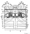
- Figure 1 is a side half-section drawing showing the upper-half of a serial ventilation device, according to a first embodiment of the present invention.
- Figure 2 is a drawing showing the serial ventilation device of Figure 1 from the intake opening side.
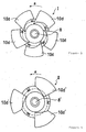
- Figure 3 is a front view of the first fan motor blades and the peripheral area.
- Figure 4 is a front view of the second fan motor blades and the peripheral area.
- Figure 5 is a front view of the first fan motor with notches drilled in the casing instead of holes.
- Figure 6 is a graph showing the P-Q characteristics of the present invention along with those of a conventional ventilation device.
- Figure 7 is a drawing showing a serial ventilation device from the intake opening side, according to another embodiment of the present invention.
- each figure shows an embodiment in which a fan motor is used in each ventilator. It should be further noted that in Figure 2, the ventilator mounted on the exhaust opening side is omitted except for the fan motor assembly holes.
- a first fan motor I (a first ventilator) is mounted on an air intake opening side of the ventilation device
- a second fan motor II (a second ventilator) is mounted on an air exhaust opening side of the ventilation device.
- the front surface of the blades of fan motor I face the air intake side while the front surface of the blades of fan motor II face the air exhaust side.
- Both fan motors I and II are formed with almost equal external dimensions, as can be seen in Figure 1, and have almost the same configuration, with the exception of the difference in a ventilation side, face direction and number of the blades.
- the common structure of the first and second fan motors are described below using only the elements of fan motor I.
- the elements of fan motor II that are the same as those of fan motor I are indicated by the same reference numbers with a prime. Explanation of these same elements is accordingly omitted.
- Fan motor I has rectangular (vertical) casing 1, wherein circular air vent 1a is formed in the center region of square area 31, which is positioned in the center region of the vertical direction of that rectangle. Assembly holes 1b are formed in each corner to assemble fan motor I to the device case (not shown).
- motor base 4 In the center region of air vent 1a in casing 1, motor base 4 is held fixed by ribs 3 (in this case three ribs), that extend from the surrounding edge of the opening of air vent 1a.
- Tubular bearing support 5 is anchored to the center region of this motor base 4.
- the outer races of two bearings 6 and 7 are supported at an interval inside bearing support 5, and motor rotation shaft 8 is inserted into and supported by the inner circumference of bearings 6 and 7.
- Retaining ring 9 is mounted to the end of rotation shaft 8 and prevents slipping of rotation shaft 8 as well as fixing the axial direction.
- Fan motor I further has an impeller 10, wherein multiple blades 10d are arranged at equal intervals in the direction of rotation on an outer circumference of impeller body 10c, which has a cylinder 10a and a boss 10b.
- This impeller 10 is coupled to the rear end of rotation shaft 8 by boss 10b, which is positioned above the central axis 4a of impeller body 10c and cylinder 10a, and is configured such that blades 10d rotate around rotation shaft 8 when rotation shaft 8 rotates.
- Coil spring 11 is fitted between the inner face of bearing 7 and boss 10b, providing deflection force to boss 10b, and thus to impeller 10, in the direction of the rear end of rotation shaft 8.
- a nearly cylindrical motor yoke 12 is inserted and mounted to the inner circumference of impeller 10 and cylinder 10a, and cylindrical permanent magnet 13 is affixed to the inner circumference of this motor yoke 12.
- a direct current motor comprising stator coil 14 and a stator iron core 15, conducted by stator coil 14, are fixed to the exterior of bearing support 5.
- a circuit board in this case PC board 16, is positioned that has electronic circuits for supplying a fixed current to stator coil 14.
- the electronic circuits on PC board 16 controls the electric current supply to stator coil 14 in order to make the motor yoke 12 permanent magnet 13 side rotate against the stator 14 iron core 15 side.
- lead wires that supply electric power to PC board 16 are connected to PC board 16.
- fan motors I and II are in the same direction. In other words, facing the forward (exhaust) direction. Moreover they are configured such that, when rotating in the same counter-clockwise direction ⁇ (forward rotation), fan motor I performs regular ventilation from the rear blade surface and fan motor II performs regular ventilation from the front blade surface. Accordingly, regular ventilation is ventilation in the direction actively intended in the design of fan motors I and II.
- the number of blades 10d of fan motor I is comparatively greater than the number of blades 10d' of fan motor II.
- the number of fan motor I blades 10d is five and the number of fan motor II blades 10d' is three. It is to be understood, of course, that while the number of blades 10d of fan motor I is greater than the number of blades 10d' of fan motor II, that it is acceptable to make the number of blades 10d' of fan motor II greater than the number of blades 10d of fan motor I. In this embodiment as well, the same effect (airflow increase) as the above embodiment is obtained. Further, it is also to be understood, of course, that more or less blades may be used depending on specifications.
- both fan motors I and ll are connected by screws, however, it is to be understood that it is acceptable to use other methods to connect them.
- fan motors I and II are connected by screws, screw holes or notches are drilled into fan motors I and II.
- hole 21 with a diameter larger than the screw portion of the self-tapping screw (not shown) used for connecting is drilled through the side of the fan motor I and hole 22 with a diameter slightly smaller than that same screw portion is drilled through the side of the fan motor II.
- fan motors I and II are connected by screwing the self-tapping screw through the fan motor I hole 21 to the fan motor II hole 22.
- any position is acceptable except for a position in a straight line above the fan motor assembly holes 1b, 1b' in casings 1,1'. In other words, as long as it is a position that does not impede assembly of the serial ventilation device of the present invention at the desired position using holes 1b, 1b'.
- casings 1,1' are formed in a rectangular shape as shown in Figures 1 and 2, it is acceptable to set the screw position anywhere in rectangular regions 32 and 33, except for the square region 31 that houses the fan motor itself (roughly the structural portion of the device excepting casings 1, 1'). In this manner, positioning of the screw holes or notches (holes 21, 22; notch 23) for connecting fan motors I and II is made easier.
- FIG. 6 the static pressure P and air flow Q characteristics of the serial ventilation device of an embodiment of the present invention are shown.
- a flag R for the same characteristics for a conventional serial ventilation device (conventional device) are also shown.
- Curve 1 shows the P-Q characteristics of the present invention and curve 2 shows the P-Q characteristics of the conventional device.
- curve 3 shows the rotation speed-airflow characteristics of the present invention and curve 4 shows the rotation speed-airflow characteristics of the conventional device.
- FIG. 7 another embodiment of the serial ventilation device is shown.
- case 1 in a square shape and set screw holes 73 for connecting fan motors I and II in peripheral region 72, which excludes square area 71 that houses the fan motor itself (like square area 31 in Figure 2).
- square-shape includes “nearly square-shape.”
- notches in place of holes 73, it is acceptable to use notches (not shown) similar to notch 23 shown in Figure 5. Accordingly, in this manner screw holes 73, or similar notches, are not limited to the same positioning limits as shown in Figure 2.
- the reference numbers for the elements of the fan motor shown in Figure 7 that are identical to the elements of the fan motor in Figure 2 are the same.
- serial ventilation device of the above embodiments can be attached to the vent holes of an electronic device case (not shown) and/or an office equipment case (not shown). In such use the device would be attached, for example, with the center right side of Figure 1 facing the exterior of the electronic device/ equipment case.
- first fan motor I rotates in counter clockwise direction ⁇ as seen from the front side of the blades (the intake opening side of the device), and will perform ventilation facing from center left to the right side of Figure 1, in other words to the rear side of the blades.
- second fan motor II rotates in counter clockwise direction ⁇ as seen from the front side of the blades (the exhaust opening side of the device), and will perform ventilation from center left to the right side of Figure 1, in other words to the front side of the blades.
- the serial ventilation device as a whole will ventilate from the center left of Figure 1 toward the right (refer to arrow ⁇ ).
- a first ventilator that ventilates from the rear side of the blades and a second ventilator that ventilates from the front side of the blades when all of the blades are rotated in the same direction and in which the ventilation surface of the blades are facing the same direction. That is, the first ventilator is mounted to the intake opening side of a device with the front surface of its blades facing the air intake side while the second ventilator is mounted to the exhaust opening side of the device with the front surface of its blades facing the air exhaust side. Then, both ventilators are connected serially such that their rotation shafts are positioned on the same straight line.
- the number of blades of the first ventilator is set higher or lower than the number of blades of second ventilator, thus obtaining the P-Q characteristics shown, for example, in Figure 6. In this way, airflow increase can be realized in comparison with the conventional serial ventilation device without enlarging the shape or size.
Abstract
Description
- The present invention relates to an apparatus for a ventilation device, such as that used for exhausting heat generated inside the case of electronics devices or equipment to the exterior, and more particularly to a serial ventilation device in which two ventilators are placed longitudinally and operate at the same time.
- In electronic devices in which many electronic components are housed in a relatively small case, such as office equipment like personal computers and copiers, heat generated by these electronic components collects inside the case and there is concern that the electronic components will experience heat failure.
- Accordingly, vent holes have been created in the walls or roof of the cases for these electronic devices and ventilators attached to these vent holes exhaust the heat inside the case to the outside. As methods to force heat exhaust using ventilators there is the normal method, using one ventilator, and the serial operation and parallel operation methods, using two ventilators with good external shape and characteristics in combination at the same time.
- In the serial operation method, two ventilators are placed longitudinally facing the same direction such that their rotation shafts are positioned in a straight line and they operate in the same direction at the same time. This method is designed mainly to increase static pressure P. In the parallel operation method, two ventilators are mounted laterally facing the same direction such that their rotation shafts are positioned in parallel and they operate in the same direction at the same time. This method is designed mainly to increase airflow Q.
- Accordingly, engineers select the serial operation method or the parallel operation method depending on physical conditions, such as the available mounting space for two ventilators, and/or required specifications such as which of increasing static pressure P or airflow Q has priority. However, in recent years, the miniaturization of electronic devices has been remarkable and the consequent need for improvement in the heat exhaust characteristics required for ventilation devices is notable. For instance, in ventilation devices using the serial operation method (i.e., serial ventilation devices) the effect of even a small increase in airflow Q on the efficiency of exhausting heat generated inside an electronics device's case is large. Accordingly, even for serial ventilation devices recently there have been demands for further increases in airflow Q without increasing the size.
- Accordingly, the present invention is directed to a serial ventilation device that increases airflow Q without increasing the size.
- The construction of the serial ventilation device of the present invention is characterized by a casing of almost equal external dimensions housing the body of the ventilators including the blades. The device has a first ventilator which performs regular ventilation from the rear side of the blades, and a second ventilator which performs regular ventilation from the front side of the blades. Ventilation occurs when the ventilation side of the blades are facing the same direction and rotating in the same direction. The first ventilator is mounted on the air intake opening side of the device, with the front surface of its blades facing the air intake side. The second ventilator is mounted on the air exhaust opening side of the device, with the front surface of its blades facing the air exhaust side. Both ventilators are placed in succession in a serial state, with the rotation shafts positioned on the same line, and the number of blades of the first ventilator is different from the number of blades of the second ventilator.
- An embodiment of the invention is characterized by external dimensions of the casings for each of the ventilators being formed such that they perforated with assembly holes in the same location at each corner and, in each casing, in a position that is contiguous when the ventilators are placed in series, excluding the position that links the assembly holes of the ventilators in a straight line (i.e., a screw hole or a notch located in order to mutually connect the ventilators).
- An embodiment of the present invention is further characterized by external dimensions of the casing formed in a rectangle, and, in the area of this rectangle, excluding the square area within the rectangle that houses the body of the ventilators, screw holes or notches located in order to mutually connect the ventilators.
- Yet another embodiment of the present invention is characterized by external dimensions of the casing formed in a square, and, in the area of this square, excluding the square area within the square that houses the body of the ventilators, screw holes or notches located in order to mutually connect the ventilators.
- The present invention, including its features and advantages, will become more apparent from the following detailed description with reference to the accompanying drawings.
- Figure 1 is a side half-section drawing showing the upper-half of a serial ventilation device, according to a first embodiment of the present invention.
- Figure 2 is a drawing showing the serial ventilation device of Figure 1 from the intake opening side.
- Figure 3 is a front view of the first fan motor blades and the peripheral area.
- Figure 4 is a front view of the second fan motor blades and the peripheral area.
- Figure 5 is a front view of the first fan motor with notches drilled in the casing instead of holes.
- Figure 6 is a graph showing the P-Q characteristics of the present invention along with those of a conventional ventilation device.
- Figure 7 is a drawing showing a serial ventilation device from the intake opening side, according to another embodiment of the present invention.
- Below, the different embodiments of the present invention are explained with reference to the drawings. It should be noted that each figure shows an embodiment in which a fan motor is used in each ventilator. It should be further noted that in Figure 2, the ventilator mounted on the exhaust opening side is omitted except for the fan motor assembly holes.
- Referring now to Figures 1 and 2, a first fan motor I (a first ventilator) is mounted on an air intake opening side of the ventilation device, and a second fan motor II (a second ventilator) is mounted on an air exhaust opening side of the ventilation device. The front surface of the blades of fan motor I face the air intake side while the front surface of the blades of fan motor II face the air exhaust side. Both fan motors I and II are formed with almost equal external dimensions, as can be seen in Figure 1, and have almost the same configuration, with the exception of the difference in a ventilation side, face direction and number of the blades. For the sake of brevity, the common structure of the first and second fan motors are described below using only the elements of fan motor I. The elements of fan motor II that are the same as those of fan motor I are indicated by the same reference numbers with a prime. Explanation of these same elements is accordingly omitted.
- Fan motor I has rectangular (vertical)
casing 1, whereincircular air vent 1a is formed in the center region ofsquare area 31, which is positioned in the center region of the vertical direction of that rectangle.Assembly holes 1b are formed in each corner to assemble fan motor I to the device case (not shown). - In the center region of
air vent 1a incasing 1, motor base 4 is held fixed by ribs 3 (in this case three ribs), that extend from the surrounding edge of the opening ofair vent 1a.Tubular bearing support 5 is anchored to the center region of this motor base 4. The outer races of twobearings support 5, andmotor rotation shaft 8 is inserted into and supported by the inner circumference ofbearings rotation shaft 8 and prevents slipping ofrotation shaft 8 as well as fixing the axial direction. - Fan motor I further has an
impeller 10, whereinmultiple blades 10d are arranged at equal intervals in the direction of rotation on an outer circumference ofimpeller body 10c, which has acylinder 10a and aboss 10b. Thisimpeller 10 is coupled to the rear end ofrotation shaft 8 byboss 10b, which is positioned above thecentral axis 4a ofimpeller body 10c andcylinder 10a, and is configured such thatblades 10d rotate aroundrotation shaft 8 whenrotation shaft 8 rotates.Coil spring 11 is fitted between the inner face of bearing 7 andboss 10b, providing deflection force toboss 10b, and thus to impeller 10, in the direction of the rear end ofrotation shaft 8. - A nearly
cylindrical motor yoke 12 is inserted and mounted to the inner circumference ofimpeller 10 andcylinder 10a, and cylindricalpermanent magnet 13 is affixed to the inner circumference of thismotor yoke 12. Along with themotor yoke 12 andpermanent magnet 13, a direct current motor (DCM) comprisingstator coil 14 and astator iron core 15, conducted bystator coil 14, are fixed to the exterior ofbearing support 5. In the vicinity ofstator iron core 15, a circuit board, in thiscase PC board 16, is positioned that has electronic circuits for supplying a fixed current tostator coil 14. The electronic circuits onPC board 16 controls the electric current supply tostator coil 14 in order to make themotor yoke 12permanent magnet 13 side rotate against thestator 14iron core 15 side. Although not shown in the figures, lead wires that supply electric power toPC board 16 are connected toPC board 16. - Referring now to figures 3 and 4, the ventilation side, face direction and number of the blades of fan motors I and II are described as follows.
- The ventilation blade surfaces of fan motors I and II are in the same direction. In other words, facing the forward (exhaust) direction. Moreover they are configured such that, when rotating in the same counter-clockwise direction α (forward rotation), fan motor I performs regular ventilation from the rear blade surface and fan motor II performs regular ventilation from the front blade surface. Accordingly, regular ventilation is ventilation in the direction actively intended in the design of fan motors I and II.
- In addition, the number of
blades 10d of fan motor I is comparatively greater than the number ofblades 10d' of fan motor II. In an embodiment shown by the drawing, the number of fan motor Iblades 10d is five and the number of fan motor IIblades 10d' is three. It is to be understood, of course, that while the number ofblades 10d of fan motor I is greater than the number ofblades 10d' of fan motor II, that it is acceptable to make the number ofblades 10d' of fan motor II greater than the number ofblades 10d of fan motor I. In this embodiment as well, the same effect (airflow increase) as the above embodiment is obtained. Further, it is also to be understood, of course, that more or less blades may be used depending on specifications. - Referring again to Figures 1 and 2, and now also to Figure 5, both fan motors I and ll are connected by screws, however, it is to be understood that it is acceptable to use other methods to connect them. In the case that fan motors I and II are connected by screws, screw holes or notches are drilled into fan motors I and II. As shown in Figures 1 and 2,
hole 21 with a diameter larger than the screw portion of the self-tapping screw (not shown) used for connecting is drilled through the side of the fan motor I andhole 22 with a diameter slightly smaller than that same screw portion is drilled through the side of the fan motor II. In this configuration, fan motors I and II are connected by screwing the self-tapping screw through the fan motor Ihole 21 to the fan motor IIhole 22. - Regarding the fan motor I side, instead of
hole 21, drilling anotch 23 as shown in Figure 5 is acceptable. In this manner, work to connect fan motors I and II is made easier by omitting the alignment of the self-tapping screw end to hole 21 shown in Figures 1 and 2. Although not shown, it is also acceptable to make the holes in fan motors I, II of equal diameter and connect fan motors I and II by inserting a bolt through the holes and screwing a nut onto the end of the bolt. In this example as well, by drilling a notch instead of a hole in the fan motor I side, work to connect fan motors I, II is made easier. - Regarding the positioning of the
holes motor assembly holes casings 1,1'. In other words, as long as it is a position that does not impede assembly of the serial ventilation device of the present invention at the desiredposition using holes - In an embodiment wherein
casings 1,1' are formed in a rectangular shape as shown in Figures 1 and 2, it is acceptable to set the screw position anywhere inrectangular regions square region 31 that houses the fan motor itself (roughly the structural portion of thedevice excepting casings 1, 1'). In this manner, positioning of the screw holes or notches (holes 21, 22; notch 23) for connecting fan motors I and II is made easier. - Referring now to Figure 6, the static pressure P and air flow Q characteristics of the serial ventilation device of an embodiment of the present invention are shown. A flag R for the same characteristics for a conventional serial ventilation device (conventional device) are also shown.
Curve 1 shows the P-Q characteristics of the present invention and curve 2 shows the P-Q characteristics of the conventional device. Further,curve 3 shows the rotation speed-airflow characteristics of the present invention and curve 4 shows the rotation speed-airflow characteristics of the conventional device. - As shown in this figure, improvement (airflow increase) can be seen in the P-Q characteristics, particularly in the airflow P-Q characteristics, of present invention compared to the conventional device.
- Referring now to Figure 7, another embodiment of the serial ventilation device is shown. In this embodiment it is shown that it is acceptable to form
case 1 in a square shape and set screw holes 73 for connecting fan motors I and II inperipheral region 72, which excludessquare area 71 that houses the fan motor itself (likesquare area 31 in Figure 2). It is to be understood that "square-shape" includes "nearly square-shape." Also, in place ofholes 73, it is acceptable to use notches (not shown) similar to notch 23 shown in Figure 5. Accordingly, in this manner screw holes 73, or similar notches, are not limited to the same positioning limits as shown in Figure 2. The reference numbers for the elements of the fan motor shown in Figure 7 that are identical to the elements of the fan motor in Figure 2 are the same. - It is to be understood, of course, that the serial ventilation device of the above embodiments can be attached to the vent holes of an electronic device case (not shown) and/or an office equipment case (not shown). In such use the device would be attached, for example, with the center right side of Figure 1 facing the exterior of the electronic device/ equipment case.
- In this state, if a fixed voltage of electric current is supplied to lead wires (not shown) in both fan motors I and II, each operate as follows. That is, electric current controlled by electronic circuits on
PC boards 16, 16' will flow to stator coils 14, 14'. With this, magnetic flux will be generated fromstator iron cores 15, 15' andmotor yokes 12, 12', andimpellers 10, 10' (blades rotation shafts 8, 8' due to the mutual magnetic effect of that magnetic flux and the magnetic flux generated bypermanent magnets 13, 13'. - That is, first fan motor I rotates in counter clockwise direction α as seen from the front side of the blades (the intake opening side of the device), and will perform ventilation facing from center left to the right side of Figure 1, in other words to the rear side of the blades. In addition, second fan motor II rotates in counter clockwise direction α as seen from the front side of the blades (the exhaust opening side of the device), and will perform ventilation from center left to the right side of Figure 1, in other words to the front side of the blades. The serial ventilation device as a whole will ventilate from the center left of Figure 1 toward the right (refer to arrow β).
- As a result, the air in the center left side of Figure 1, in other words the interior of the equipment case, will be sucked in and through
vent holes - It is to be understood, of course, that while in the above embodiments an outer rotor-type motor was used as the motor to rotate the blades, it is not limited thereto, and an inner rotor-type motor can also be used. Moreover, in the above embodiments the use of the serial ventilation device inside the case of an electronic device to exhaust heat is explained, however, it is also acceptable to use the serial ventilation device to bring outside air into the electronic device case, etc., by changing the direction of ventilation to the direction opposite that of the above embodiments.
- In the present invention above, a first ventilator that ventilates from the rear side of the blades and a second ventilator that ventilates from the front side of the blades when all of the blades are rotated in the same direction and in which the ventilation surface of the blades are facing the same direction is described. That is, the first ventilator is mounted to the intake opening side of a device with the front surface of its blades facing the air intake side while the second ventilator is mounted to the exhaust opening side of the device with the front surface of its blades facing the air exhaust side. Then, both ventilators are connected serially such that their rotation shafts are positioned on the same straight line. Furthermore the number of blades of the first ventilator is set higher or lower than the number of blades of second ventilator, thus obtaining the P-Q characteristics shown, for example, in Figure 6. In this way, airflow increase can be realized in comparison with the conventional serial ventilation device without enlarging the shape or size.
- In the foregoing description, the apparatus and method of the present invention have been described with reference to specific examples. It is to be understood and expected that variations in the principles of the apparatus and method herein disclosed may be made by one skilled in the art and it is intended that such modifications, changes, and substitutions are to be included within the scope of the present invention as set forth in the appended claims. The specification and drawings are accordingly to be regarded in an illustrative rather than in a restrictive sense.
Claims (13)
- An apparatus for a serial ventilation device comprising:wherein the first ventilator performs ventilation from a rear surface of the at least one blade, and the second ventilator performs ventilation from the front surface of the at least one blade.a casing;a first ventilator, mounted on an air intake opening side of the casing, having at least one blade with a front surface facing the air intake opening side; anda second ventilator, mounted on an air exhaust opening side of the casing, having at least one blade with a front surface facing the air exhaust side opening side,
- The apparatus according to claim 1, wherein the first and second ventilators each further comprise:a rotation shaft, around which the at least one blade rotates, andfurther wherein the rotation shaft of each of the first and second ventilators are positioned axially in the same line.
- The apparatus according to claim 1 or 2, further comprising:at least one rib attached to the casing;a motor base fixed to the at least one rib;a bearing support, having a tubular shape and anchored to the motor base;at least one bearing supported by the bearing support; anda rotation shaft supported by an inner circumference of the at least one bearing.
- The apparatus according to any preceding claim, further comprising:an impeller, on which the at least one blade is affixed; anda rotation shaft, to which the impeller is coupled so as to be able to rotate.
- The apparatus according to any preceding claim, wherein the at least one blade of each of the first and second ventilators rotates in the same direction.
- An apparatus for a serial ventilation device comprising:wherein the first and second ventilator are attached to one another in series such that they ventilate air along the same line in the same direction.a first ventilator having at least one blade;a second ventilator having at least one blade fewer than the first ventilator,
- The apparatus according to claim 6, wherein a front side of the at least one blade of the first ventilator faces in an opposite direction from a front side of the at least one blade of the second ventilator.
- The apparatus according to claim 6 or 7, wherein the first ventilator is positioned on an air intake opening side of the casing, and the second ventilator is positioned on an air exhaust opening side of the casing.
- The apparatus according to any of claims 6 to 8, wherein the first and second ventilators each further comprise:a rotation shaft, around which the at least one blade rotates.
- The apparatus according to any of claims 6 to 9, further comprising:a casing in which the first and second ventilators are housed.
- The apparatus according to claim 10, further comprising:at least one rib attached to the casing;a motor base fixed to the at least one rib;a bearing support, having a tubular shape and anchored to the motor base;at least one bearing supported by the bearing support; anda rotation shaft supported by an inner circumference of the at least one bearing.
- The apparatus according to any of claims 6 to 11, further comprising:an impeller, on which the at least one blade is affixed; anda rotation shaft, to which the impeller is coupled so as to be able to rotate.
- The apparatus according to any of claims 6 to 12, wherein the at least one blade of each of the first and second ventilators rotates in the same direction.
Applications Claiming Priority (2)
| Application Number | Priority Date | Filing Date | Title |
|---|---|---|---|
| JP2002197289 | 2002-07-05 | ||
| JP2002197289A JP2004036569A (en) | 2002-07-05 | 2002-07-05 | Serial fan device |
Publications (1)
| Publication Number | Publication Date |
|---|---|
| EP1379117A1 true EP1379117A1 (en) | 2004-01-07 |
Family
ID=29720317
Family Applications (1)
| Application Number | Title | Priority Date | Filing Date |
|---|---|---|---|
| EP03254197A Withdrawn EP1379117A1 (en) | 2002-07-05 | 2003-07-01 | Serial ventilation device |
Country Status (5)
| Country | Link |
|---|---|
| US (1) | US7175399B2 (en) |
| EP (1) | EP1379117A1 (en) |
| JP (1) | JP2004036569A (en) |
| CN (1) | CN1475675A (en) |
| TW (1) | TW200405789A (en) |
Families Citing this family (12)
| Publication number | Priority date | Publication date | Assignee | Title |
|---|---|---|---|---|
| JP2007303333A (en) * | 2006-05-10 | 2007-11-22 | Nippon Densan Corp | Contra-rotating axial flow fan |
| JP3953503B1 (en) * | 2006-07-05 | 2007-08-08 | 山洋電気株式会社 | Brushless fan motor |
| JP3904595B1 (en) * | 2006-11-08 | 2007-04-11 | 山洋電気株式会社 | Counter-rotating axial fan |
| WO2008099707A1 (en) | 2007-02-16 | 2008-08-21 | Sanyo Electric Co., Ltd. | Optical pickup device and recording/reproduction device |
| JP5286689B2 (en) * | 2007-04-17 | 2013-09-11 | 日本電産株式会社 | Cooling fan unit |
| JP4076570B1 (en) * | 2007-04-18 | 2008-04-16 | 山洋電気株式会社 | Counter-rotating axial fan |
| JP5363138B2 (en) | 2009-02-25 | 2013-12-11 | ミネベア株式会社 | Fan device |
| US9651054B2 (en) * | 2014-02-11 | 2017-05-16 | Asia Vital Components Co., Ltd. | Series fan frame body structure made of different materials |
| US9657742B2 (en) * | 2014-09-15 | 2017-05-23 | Speedtech Energy Co., Ltd. | Solar fan |
| CN109519398A (en) * | 2017-09-18 | 2019-03-26 | 台达电子工业股份有限公司 | Fan |
| JP7119635B2 (en) * | 2018-06-22 | 2022-08-17 | 日本電産株式会社 | axial fan |
| CN113323901B (en) * | 2021-06-09 | 2023-04-07 | 奇鋐科技股份有限公司 | Series fan |
Citations (7)
| Publication number | Priority date | Publication date | Assignee | Title |
|---|---|---|---|---|
| DE2503623A1 (en) * | 1975-01-29 | 1976-08-05 | Siemens Ag | Ventilating system for switchgear cabinet - has additional fan released by electromagnet as standby to main fan when its failure |
| US5546272A (en) * | 1995-01-18 | 1996-08-13 | Dell Usa, L.P. | Serial fan cooling subsystem for computer systems |
| EP0761982A1 (en) * | 1995-08-03 | 1997-03-12 | Valeo Thermique Moteur | Fan module |
| US6244818B1 (en) * | 1999-03-02 | 2001-06-12 | Delta Electronics, Inc. | Fan guard structure for additional supercharging function |
| TW471562U (en) * | 2001-02-27 | 2002-01-01 | Delta Electronics Inc | Backup heat dissipation system for serial fans |
| US6396688B1 (en) * | 2000-03-29 | 2002-05-28 | Dell Products L.P. | Series fan speed control system |
| US6626653B2 (en) * | 2001-01-17 | 2003-09-30 | Delta Electronics Inc. | Backup heat-dissipating system |
Family Cites Families (19)
| Publication number | Priority date | Publication date | Assignee | Title |
|---|---|---|---|---|
| US1541443A (en) * | 1924-04-19 | 1925-06-09 | Thelen Rolf | Reversible circulation internal fan kiln |
| US1866127A (en) * | 1929-08-16 | 1932-07-05 | Emerson Electric Mfg Co | Fan |
| US1968874A (en) * | 1931-06-18 | 1934-08-07 | Cobb James Forrest | Dry kiln |
| US2288154A (en) * | 1938-01-10 | 1942-06-30 | Moore Dry Kiln Co | Dry kiln and the art of kiln drying |
| US2325222A (en) * | 1939-10-16 | 1943-07-27 | Walter H Bretzlaff | Air impelling apparatus |
| US3054230A (en) * | 1959-03-13 | 1962-09-18 | Denver Equip Co | Sand scrubber |
| US3347310A (en) * | 1964-10-21 | 1967-10-17 | Frigikar Corp | Heat exchangers |
| US3315488A (en) * | 1966-04-05 | 1967-04-25 | Cummins Engine Co Inc | Refrigeration apparatus |
| US3387769A (en) * | 1966-10-03 | 1968-06-11 | Worthington Corp | Multistage turbomachine |
| US4098008A (en) * | 1976-11-08 | 1978-07-04 | Wellons, Inc. | Dry kiln having bidirectional air flow with unidirectional fan rotation |
| SE445107B (en) * | 1983-06-22 | 1986-06-02 | Volvo Penta Ab | ROTOR DEVICE |
| US5007241A (en) * | 1989-09-12 | 1991-04-16 | Saito Yutaka | Kinetic energy recovery device of liquid and gas |
| US5572403A (en) * | 1995-01-18 | 1996-11-05 | Dell Usa, L.P. | Plenum bypass serial fan cooling subsystem for computer systems |
| JPH0989344A (en) * | 1995-09-25 | 1997-04-04 | Mitsubishi Electric Corp | Fan |
| JP3425308B2 (en) * | 1996-09-17 | 2003-07-14 | 株式会社 日立インダストリイズ | Multistage compressor |
| US6129528A (en) * | 1998-07-20 | 2000-10-10 | Nmb Usa Inc. | Axial flow fan having a compact circuit board and impeller blade arrangement |
| JP3510120B2 (en) * | 1998-10-07 | 2004-03-22 | 山洋電気株式会社 | Blower with waterproof structure |
| JP4491903B2 (en) * | 2000-04-14 | 2010-06-30 | パナソニック株式会社 | Blower |
| US6537019B1 (en) * | 2000-06-06 | 2003-03-25 | Intel Corporation | Fan assembly and method |
-
2002
- 2002-07-05 JP JP2002197289A patent/JP2004036569A/en active Pending
-
2003
- 2003-07-01 EP EP03254197A patent/EP1379117A1/en not_active Withdrawn
- 2003-07-02 US US10/612,116 patent/US7175399B2/en not_active Expired - Fee Related
- 2003-07-02 TW TW092118104A patent/TW200405789A/en unknown
- 2003-07-04 CN CNA031462529A patent/CN1475675A/en active Pending
Patent Citations (7)
| Publication number | Priority date | Publication date | Assignee | Title |
|---|---|---|---|---|
| DE2503623A1 (en) * | 1975-01-29 | 1976-08-05 | Siemens Ag | Ventilating system for switchgear cabinet - has additional fan released by electromagnet as standby to main fan when its failure |
| US5546272A (en) * | 1995-01-18 | 1996-08-13 | Dell Usa, L.P. | Serial fan cooling subsystem for computer systems |
| EP0761982A1 (en) * | 1995-08-03 | 1997-03-12 | Valeo Thermique Moteur | Fan module |
| US6244818B1 (en) * | 1999-03-02 | 2001-06-12 | Delta Electronics, Inc. | Fan guard structure for additional supercharging function |
| US6396688B1 (en) * | 2000-03-29 | 2002-05-28 | Dell Products L.P. | Series fan speed control system |
| US6626653B2 (en) * | 2001-01-17 | 2003-09-30 | Delta Electronics Inc. | Backup heat-dissipating system |
| TW471562U (en) * | 2001-02-27 | 2002-01-01 | Delta Electronics Inc | Backup heat dissipation system for serial fans |
Also Published As
| Publication number | Publication date |
|---|---|
| US20040076517A1 (en) | 2004-04-22 |
| US7175399B2 (en) | 2007-02-13 |
| TW200405789A (en) | 2004-04-01 |
| JP2004036569A (en) | 2004-02-05 |
| CN1475675A (en) | 2004-02-18 |
Similar Documents
| Publication | Publication Date | Title |
|---|---|---|
| US7824154B2 (en) | Motor having heat-dissipating structure for circuit component and fan unit including the motor | |
| US5925948A (en) | Axial flow fan motor | |
| US7800263B2 (en) | Heat dissipating fan | |
| JP5112574B2 (en) | Electric motor and electric device including the same | |
| US7946804B2 (en) | Axial fan unit having reduced noise generation | |
| WO2016174790A1 (en) | Centrifugal blower and cleaner | |
| US7175399B2 (en) | Serial ventilation device | |
| JP2010138895A (en) | Serial axial fan | |
| US7078844B2 (en) | Heat-dissipating device and motor structure thereof | |
| US11549513B2 (en) | Compressor | |
| JP2008082328A (en) | Centrifugal fan | |
| JP2008175158A (en) | Axial flow fan | |
| EP1536142B1 (en) | Motor-blower unit | |
| JP2016005377A (en) | Electric blower and electric cleaner using the same | |
| JP6012022B2 (en) | Brushless motor | |
| US20070264123A1 (en) | Counter-rotating fan | |
| JP2007192217A (en) | Axial-flow fan | |
| EP3319213B1 (en) | Blower | |
| CN110630533A (en) | Axial flow fan | |
| US6655918B2 (en) | Impeller of axial-flow blower | |
| CN109904971B (en) | Motor and air supply device with same | |
| US8820692B2 (en) | Motor casing and a motor utilizing the same | |
| US6939113B2 (en) | Fan with increased air flow | |
| JP5369557B2 (en) | Electric blower | |
| JP2022124456A (en) | Air blowing device and electric device comprising the same |
Legal Events
| Date | Code | Title | Description |
|---|---|---|---|
| PUAI | Public reference made under article 153(3) epc to a published international application that has entered the european phase |
Free format text: ORIGINAL CODE: 0009012 |
|
| AK | Designated contracting states |
Kind code of ref document: A1 Designated state(s): AT BE BG CH CY CZ DE DK EE ES FI FR GB GR HU IE IT LI LU MC NL PT RO SE SI SK TR |
|
| AX | Request for extension of the european patent |
Extension state: AL LT LV MK |
|
| 17P | Request for examination filed |
Effective date: 20040707 |
|
| AKX | Designation fees paid |
Designated state(s): AT BE BG CH CY CZ DE DK EE ES FI FR GB GR HU IE IT LI LU MC NL PT RO SE SI SK TR |
|
| 17Q | First examination report despatched |
Effective date: 20071217 |
|
| STAA | Information on the status of an ep patent application or granted ep patent |
Free format text: STATUS: THE APPLICATION HAS BEEN WITHDRAWN |
|
| 18W | Application withdrawn |
Effective date: 20080711 |