EP1280155A2 - Nonlinear editing system - Google Patents
Nonlinear editing system Download PDFInfo
- Publication number
- EP1280155A2 EP1280155A2 EP02255049A EP02255049A EP1280155A2 EP 1280155 A2 EP1280155 A2 EP 1280155A2 EP 02255049 A EP02255049 A EP 02255049A EP 02255049 A EP02255049 A EP 02255049A EP 1280155 A2 EP1280155 A2 EP 1280155A2
- Authority
- EP
- European Patent Office
- Prior art keywords
- editing
- clip
- track
- control point
- nonlinear
- Prior art date
- Legal status (The legal status is an assumption and is not a legal conclusion. Google has not performed a legal analysis and makes no representation as to the accuracy of the status listed.)
- Withdrawn
Links
- 239000000463 material Substances 0.000 claims abstract description 26
- 238000000034 method Methods 0.000 claims abstract description 14
- 230000000007 visual effect Effects 0.000 claims 1
- 238000010586 diagram Methods 0.000 description 18
- 230000004048 modification Effects 0.000 description 13
- 238000012986 modification Methods 0.000 description 13
- 230000008859 change Effects 0.000 description 8
- 230000003247 decreasing effect Effects 0.000 description 6
- 230000000694 effects Effects 0.000 description 6
- 230000000717 retained effect Effects 0.000 description 3
- 238000004590 computer program Methods 0.000 description 2
- 230000009286 beneficial effect Effects 0.000 description 1
- 230000005540 biological transmission Effects 0.000 description 1
- 238000007796 conventional method Methods 0.000 description 1
- 230000001419 dependent effect Effects 0.000 description 1
- 239000012467 final product Substances 0.000 description 1
- 230000010365 information processing Effects 0.000 description 1
- 230000003287 optical effect Effects 0.000 description 1
- 230000003405 preventing effect Effects 0.000 description 1
- 230000008569 process Effects 0.000 description 1
- 239000000047 product Substances 0.000 description 1
- 238000009877 rendering Methods 0.000 description 1
Images


Classifications
-
- G—PHYSICS
- G11—INFORMATION STORAGE
- G11B—INFORMATION STORAGE BASED ON RELATIVE MOVEMENT BETWEEN RECORD CARRIER AND TRANSDUCER
- G11B27/00—Editing; Indexing; Addressing; Timing or synchronising; Monitoring; Measuring tape travel
- G11B27/02—Editing, e.g. varying the order of information signals recorded on, or reproduced from, record carriers
- G11B27/031—Electronic editing of digitised analogue information signals, e.g. audio or video signals
- G11B27/034—Electronic editing of digitised analogue information signals, e.g. audio or video signals on discs
-
- G—PHYSICS
- G11—INFORMATION STORAGE
- G11B—INFORMATION STORAGE BASED ON RELATIVE MOVEMENT BETWEEN RECORD CARRIER AND TRANSDUCER
- G11B2220/00—Record carriers by type
- G11B2220/20—Disc-shaped record carriers
- G11B2220/21—Disc-shaped record carriers characterised in that the disc is of read-only, rewritable, or recordable type
- G11B2220/215—Recordable discs
- G11B2220/216—Rewritable discs
-
- G—PHYSICS
- G11—INFORMATION STORAGE
- G11B—INFORMATION STORAGE BASED ON RELATIVE MOVEMENT BETWEEN RECORD CARRIER AND TRANSDUCER
- G11B2220/00—Record carriers by type
- G11B2220/20—Disc-shaped record carriers
- G11B2220/25—Disc-shaped record carriers characterised in that the disc is based on a specific recording technology
- G11B2220/2537—Optical discs
- G11B2220/2545—CDs
-
- G—PHYSICS
- G11—INFORMATION STORAGE
- G11B—INFORMATION STORAGE BASED ON RELATIVE MOVEMENT BETWEEN RECORD CARRIER AND TRANSDUCER
- G11B27/00—Editing; Indexing; Addressing; Timing or synchronising; Monitoring; Measuring tape travel
- G11B27/10—Indexing; Addressing; Timing or synchronising; Measuring tape travel
- G11B27/34—Indicating arrangements
Definitions
- the present invention relates to a nonlinear editing method, a nonlinear editing apparatus, a program, and a recording medium storing the program.
- Embodiments of the invention seek to provide a nonlinear editing method, a nonlinear editing apparatus, a program, and a recording medium storing the program that enable intuitive editing operation using a graphical user interface displayed on a display device.
- Nonlinear editing refers to creation of desired moving-image contents (broadcasting video contents for a broadcasting program or the like and video contents for personal use) by appropriately selecting a moving-image material and an audio material or materials including both a moving-image material and an audio material (hereinafter referred to simply as "material") stored on a hard disk, joining the materials together, and giving the materials various rendering effects.
- nonlinear editing Because of advantages of nonlinear editing such as being capable of finer editing by a frame unit as compared with conventional linear editing using a magnetic tape medium, nonlinear editing has become popular not only for business use of broadcasting stations, postproduction and the like but also now for personal use at school, home and the like against a background of the spread of high-performance personal computers and digital video cameras and the spread of nonlinear editing packaged software that is easy to use and operates on the personal computers.
- MediaStudio Pro (trademark), for example, is known as nonlinear editing packaged software that operates on a general-purpose personal computer (hereinafter referred to simply as “nonlinear editing software").
- the software includes an editing tool referred to as VideoEditor, which displays a graphical editing window on a screen of the personal computer and thus provides an editing environment with excellent intuitive operability.
- FIG. 7 is a diagram showing a part of the editing window (particularly a track editing area).
- the track editing area 101 is formed by a plurality of (n in FIG. 7) tracks T1 to Tn having an axis of abscissas as a time line 102.
- a user arranges, on the tracks T1 to Tn, graphic objects referred to as "clips" indicating materials (source files) selected on the basis of intended editing, and thereby performs nonlinear editing.
- a clip C1, a clip C2, and a clip C3 are arranged in that order from the left on the first track T1, and a clip C4, a clip C5, and a clip C6 are arranged in that order from the left on the second track T2.
- the clip C1 the clip C2, and the clip C3 arranged on the track T1 each represent a video material
- the clip C4, the clip C5, and the clip C6 arranged on the second track T2 each represent an audio material.
- Such nonlinear editing requires various editing operations such as rearranging materials, changing length of a material, changing audio level and the like.
- the rearranging of materials can be performed by changing positions of the clips C1 to C6.
- the changing of the length of materials can be performed by changing length of the clips C1 to C6 (length in a horizontal direction of the graphic objects).
- These editing operations are so devised that the editing operations can be performed intuitively by using a pointing device such as a mouse or the like. Specifically, a clip can be moved by dragging and dropping the entire clip, and the length of a clip can be changed by dragging a left edge or a right edge of the clip.
- FIG. 8A is a diagram showing one audio clip (clip C4 for convenience) disposed on an arbitrary audio track (track T2 for convenience).
- Both ends of the line object 103 are provided with control point objects 104 and 105 of a given shape (small square in the figure).
- the control point objects 104 and 105 can be moved (dragged) in a vertical direction independently.
- the control point objects 104 and 105 are dragged in an upward direction (direction of 100%)
- the audio level is increased
- the control point objects 104 and 105 are dragged in a downward direction (direction of 0%)
- the audio level is decreased.
- the line object 103 changes a gradient of a straight line thereof according to the movement (drag) of the control point objects 104 and 105, thereby making it possible to intuitively perceive change of the audio level on the time axis in a visualized form.
- FIG. 8B illustrates a first example of control of the audio level.
- a new control point object 106 is added to the line object 103, and the position of the control point object 105 situated at the right edge of the clip C4 is lowered to substantially 0%.
- the audio level during reproduction of the clip C4 is maintained at substantially 50% in a range from the control point object 104 to the control point object 106, and is linearly decreased to substantially 0% in a range from the control point object 106 to the control point object 105.
- Such audio level control (first example) is used for smooth connection to a subsequent audio clip in the case of a BGM (background music) sound source, for example.
- FIG. 8C illustrates a second example of control of the audio level.
- new control point objects 107, 108, and 109 are added to the line object 103, and the position of the control point object 108 is lowered to substantially 0%.
- the audio level during reproduction of the clip C4 is maintained at substantially 50% in a range from the control point object 104 to the control point object 107, linearly decreased to substantially 0% in a range from the control point object 107 to the control point object 108, linearly increased to substantially 50% in a range from the control point object 108 to the control point object 109, and maintained at substantially 50% in a range from the control point object 109 to the control point object 105.
- Such audio level control (second example) is used when sound unnecessary for reproduction such for example as noise or the like is included in a specific portion (around the control point object 108 in the example shown in FIG. 8C) of the clip C4, for example.
- the conventional nonlinear editing software described above is so devised that an editing parameter defined on an arbitrary clip, or an editing parameter such for example as the audio level or the like is stored as information specific to the clip integrally with the clip.
- an editing parameter of the clip after the change is reset to an initial value.
- Embodiments of the present invention seek to make it possible to freely select information specific to a clip or information specific to a track where the clip is situated to be the editing parameter of the clip and to thus eliminate the need for the operation of resetting the editing parameter or the operation of initializing the editing parameter and thereby improve operability.
- a nonlinear editing method for performing editing by displaying an editing window having a area for displaying a track on a display device and disposing a clip representing a selected material on the track, the nonlinear editing method including: having a first object for representing an editing parameter specific to the clip and a second object for representing an editing parameter specific to the track on which the clip is disposed; and performing editing while selectively operating the first object and the second object.
- the editing parameter specific to the clip is operated when the first object is selected and the editing parameter specific to the track is operated when the second object is selected.
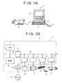
- FIGS. 1A and 1B are an external view of a personal computer and a conceptual diagram of hardware configuration of the personal computer.
- a personal computer (hereinafter abbreviated to a "PC") 1 is a general-purpose product configured by known architecture (such as DOS/V architecture or the like).
- the figures illustrate the so-called desktop type PC 1 whose main unit 2 is connected with a display device 3, a keyboard 4, a pointing device (mouse in the figures) 5, a digital video camera 6 and the like.
- the PC 1 may be a notebook type PC, a tower type PC or the like.
- the name (“personal computer” or "PC") of the PC 1 has no special meaning, and is merely a generic name.
- the PC 1 may be called otherwise, for example a "workstation,” an "office computer,” a “minicomputer,” an "information processing apparatus” or the like.
- the PC 1 may be somewhat different in configuration in terms of scale, stability and the like depending on the model, there is no significant difference in the fundamental configuration (architecture) of the so-called "computer.”
- the PC 1 shown in the figures includes, in the main unit 2, a CPU 7, a RAM 8, a disk controller 9, a CD-RW drive 10, a hard disk 12, a display controller 13, a keyboard controller 14, a digital video board 15, a main bus 16, a bus interface 17, an internal bus 18 and the like.
- the PC 1 also has the display device 3, the keyboard 4, the pointing device 5 and the like external to the main unit 2.
- the digital video camera 6 can be connected to the digital video board 15 of the main unit 2.
- the digital video camera 6 can take a picture of an arbitrary subject and generate digital moving image data of the picture.
- the digital video camera 6 is provided especially with a digital input-output interface (for example an IEEE 1394 interface) compatible with the digital video board 15.
- a digital input-output interface for example an IEEE 1394 interface
- the digital video camera 6 in the present embodiment plays a role only in providing material necessary for nonlinear editing (source files), and in this respect, the digital video camera 6 does not necessarily need to be a "camera”; the digital video camera 6 may be a digital VTR (video tape recorder), for example.
- VTR video tape recorder
- the CD-RW drive 10 is used to record digital video contents created by nonlinear editing on a write-once type (CD-R/DVD-R) or rewritable type (CD-RW/DVD-RW) optical disk 11 and thereby store or distribute the digital video contents.
- CD-R/DVD-R write-once type
- CD-RW/DVD-RW rewritable type
- the CD-RW drive 10 is not an essential component.
- the CD-RW drive 10 is not an essential component, because the digital video camera 6 or the digital VTR can be used as a recording device.
- the PC 1 loads an operating system preinstalled on the hard disk 12 and various application programs (hereinafter referred to generically as "software resources") into the RAM 8 for execution by the CPU 7, whereby the PC 1 realizes various processing functions by an organic combination of hardware resources such as the CPU 7 and the software resources.
- software resources hereinafter referred to generically as "software resources”
- One of the processing functions is a "nonlinear editing" function performed by the PC 1 alone (on a stand-alone basis).
- the nonlinear editing function will be described in detail in the following.
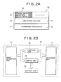
- FIG. 2A is a diagram showing a simple hierarchical model of the hardware resources and the software resources of the PC 1.
- the hierarchical model 20 follows the OSI (abbreviation of Open Systems Interconnection) reference model.
- the hierarchical model 20 has a structure in which an operating system layer 22 and an application layer 23 are stacked on a hardware resource layer 21.
- the hardware resource layer 21 includes hardware resources 24 such as the CPU 7 and the like (configuration of the main unit 2 in FIG. 1B).
- the hardware resource layer 21 can be used indirectly from the application layer 23 via an operating system 25 included in the operating system layer 22 on the hardware resource layer 21.
- the application layer 23 includes at least predetermined application program software (hereinafter referred to as "nonlinear editing software") 26 forming a main part of the nonlinear editing function.
- the nonlinear editing function in the present embodiment is realized by an organic combination of the software resources (operating system 25 and nonlinear editing software 26) and the hardware resources 24.
- FIG. 2B is a conceptual diagram of the nonlinear editing function in the present embodiment.
- a user interface unit (display control means) 27, a capture unit 28, an editing unit (operation control means) 29, an effect unit 30 and a database unit 31 in the figure correspond to the nonlinear editing software 26 in FIG. 2A.
- the user interface unit 27 outputs various graphical user interfaces (GUIs) to display resources of the hardware resources 24 (that is, the display controller 13 and the display device 3).
- GUIs graphical user interfaces
- a user creates desired digital video contents by selectively using the capture unit 28, the editing unit 29, and the effect unit 30 while interacting with the GUIs.
- the capture unit 28 is in charge of processing of reading image data from the digital video camera 6, capturing a desired portion (scene or the like) of the image data and creating material (source file), and storing the material (source file) on the hard disk 12.
- the editing unit 29 is in charge of processing of selecting materials stored on the hard disk 12, joining the materials together, giving the materials special effects or the like, and thereby creating digital video contents.
- the effect unit 30 is in charge of processing of giving digital video contents various special effects required.
- the database unit 31 manages information (referred to as a project file) on the creation of digital video contents.
- the entity of a project file is present on the hard disk 12. During the creation of digital video contents, a copy of the entity is made in the RAM 8 and the database unit 31 manages the copy.
- the copy is written back to the hard disk 12 to update the project file.
- a final product for example an MPEG file or the like
- the digital video contents is created on the basis of the project file.
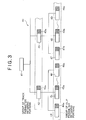
- FIG. 3 is a schematic structural diagram of a project file.
- the project file 40 has a hierarchical structure provided with a file information portion 41 in an upper layer, track information portions 42 and 43 in a middle layer, and clip information portions 44 to 49 in a lower layer.
- the file information portion 41 in the uppermost layer has the first track information portion 42 and the second track information portion 43 under the file information portion 41.
- the first track information portion 42 has three clip information portions 44 to 46 under the first track.
- information portion 42 and the second track information portion 43 has three clip information portions 47 to 49 under the second track information portion 43.
- the first track information portion 42 controls the three clip information portions 44 to 46
- the second track information portion 43 controls the three clip information portions 47 to 49
- the file information portion 41 in the uppermost layer controls the first and second track information portions 42 and 43.
- one file information portion (file information portion 41 in the figure) is provided in the uppermost layer per project file in all cases, and one or a plurality of track information portions and one or a plurality of clip information portions are provided per project file.
- the file information portion 41 stores information specific to the project file 40 (such as the name of the project file, the name of the creator, the date of file creation, the date of file update, file size and the like).
- the track information portions 42 and 43 each store information specific to the track, such for example as editing track type (video track type or audio track type), track number, track length, IN point/OUT point and the like.
- the clip information portions 44 to 49 each store information specific to the clip, such for example as information on where a material (source file) associated with the clip is stored, clip number, clip length, IN point/OUT point and the like.
- the present embodiment is characterized in that all the track information portions 42 and 43 and all the clip information portions 44 to 49 in the project file 40 having the above structure are provided with editing parameter retaining portions (portions shown hatched for convenience) 42a to 49a.
- Track editing parameter retaining portions 42a and 43a of the editing parameter retaining portions 42a to 49a store editing parameters of the corresponding tracks, while clip editing parameter retaining portions 44a to 49a of the editing parameter retaining portions 42a to 49a store editing parameters of the corresponding clips.
- the editing parameters to be stored are for example audio level setting editing parameters, or more specifically, data on change in audio level along a time axis (time line), and are, in short, audio level set values in each frame.
- the track editing parameter retaining portions 42a and 43a are identical with the clip editing parameter retaining portions 44a to 49a in that the track editing parameter retaining portions 42a and 43a and the clip editing parameter retaining portions 44a to 49a both retain such editing parameters (audio setting editing parameters), and the track editing parameter retaining portions 42a and 43a are different from the clip editing parameter retaining portions 44a to 49a in the time axis.
- the track editing parameter retaining portions 42a and 43a are different from the clip editing parameter retaining portions 44a to 49a in that the track editing parameter retaining portions 42a and 43a retain the editing parameter in correspondence with a time axis having a start position (IN point) or the like of the corresponding "track” as a reference point (00:00:00:00) (hour: minute: second: frame) whereas the clip editing parameter retaining portions 44a to 49a retain the editing parameter in correspondence with a time axis having a start position (IN point) or the like of the corresponding "clip” as a reference point (00:00:00:00) (same as above).
- the track editing parameter retaining portion 42a stores data indicating that audio level is set to x% at a certain point in time (for example 00:01:01:01), the data indicates that the audio level is set to x% at a first frame 0 hours, 1 minute, 1 second from the reference point of the corresponding "track.” If the same data is retained by the clip editing parameter retaining portion 44a, the data indicates a point after the lapse from the reference point of the corresponding "clip.” Thus, the data retained by the track editing parameter retaining portion 42a and the data retained by the clip editing parameter retaining portion 44a indicate different times.
- FIGS. 4A, 4B, and 4C are diagrams showing GUIs (editing windows) of the present embodiment.
- the GUI 50 show a portion corresponding to the track T2 in the foregoing conventional technique (see FIGS. 8A, 8B, and 8C).
- a clip C4 is pasted on the track T2, and the clip C4 has a line object (first object) 51 disposed thereon and control point objects (first objects) 52 to 56 situated on the line object 51.
- the line object 51 and the control point objects 52 to 56 represent the set value of the audio editing parameter of the clip C4.
- the line object 51 and the control point objects 52 to 56 in the example of FIG.
- the audio level in a range from the control point object 52 to the control point object 53 is maintained at b%; the audio level in a range from the control point object 53 to the control point object 54 is linearly decreased from b% to c%; the audio level in a range from the control point object 54 to the control point object 55 is linearly increased from c% to b%; and the audio level in a range from the control point object 55 to the control point object 56 is maintained at b%.
- a line object (second object) 57 and control point objects (second objects) 58 to 60 situated on the line object 57 are also disposed on the track T2.
- the line object 57 and the control point objects 58 to 60 represent the set value of the audio editing parameter of the track T2.
- the line object 57 and the control point objects 58 to 60 in the example of FIG. 4A indicate that the audio level in a range from the control point object 58 to the control point object 59 is maintained at a%; and the audio level in a range from the control point object 59 to the control point object 60 is linearly decreased from a% to c% .
- the former is specific to the clip C4 and the latter is specific to the track T2.
- the object sets are generated by reference to the clip editing parameter storing portion 44a to 49a and the track editing parameter storing portion 42a or 43a of the project file 40 described above.
- the line object 51 and the control point objects 52 to 56 specific to the clip C4 are generated by reference to data stored in one of the clip editing parameter storing portions 44a to 49a (editing parameter storing portion corresponding to the clip C4).
- the line object 57 and the control point objects 58 to 60 specific to the track T2 are generated by reference to data stored in one of the track editing parameter storing portions 42a and 43a (editing parameter storing portion corresponding to the track T2).
- the line object (57 in FIG. 4A) and the control point objects (58 to 60 in FIG. 4A) specific to the track can be displayed on the GUI 50, and also the line object (51 in FIG. 4A) and the control point objects (52 to 56 in FIG. 4A) specific to the clip can be displayed on the GUI 50.
- the clip C4 is deleted and a new clip C4' is inserted in that position, as shown in FIG. 4B, for example, an initialized line object (first object) 61 and initialized control point objects (first objects) 62 and 63 are newly displayed on the inserted clip C4'. Therefore, it is not necessary to reset the set value of the audio level.
- the set values (fade-out) of the line object 57 and the control point objects 58 to 60 set as information specific to the track T2 as shown in FIG. 4B can be used as they are, regardless of whether the clip C4 is deleted or not, and thus the clip can be changed freely.
- the line object 51 and the control point objects 52 to 56 as shown in the figure are set on the clip C4, whereby reproduction of the noise or the like can be prevented and the reproduction preventing effect is not lost even after the movement of the clip C4.
- the structure of the project file 40 is devised to allow not only an editing parameter specific to a clip but also an editing parameter specific to a track to be stored.
- an object set specific to the clip set of a line object and control point objects
- an object set specific to the track are generated on the basis of the stored information. Therefore, the following especially beneficial effects can be obtained:
- FIG. 5A is a diagram showing a first modification of the present embodiment.
- a command button object 71 is disposed in a title displaying area 70 of a track T2.
- the command button object 71 is a so-called toggle button, and title display is changed to "track” or "clip” each time the command button object 71 is clicked.
- the line object 72 and the control point objects 73 to 75 are specific to the clip C4. Therefore, when the clip C4 is moved as shown in FIG. 5B, for example, the line object 72 and the control point objects 73 to 75 are moved together with the clip C4, so that the audio level does not need to be set again at a position after the movement of the clip C4.
- the line object 72 and the control point objects 73 to 75 are specific to the track T2. Therefore, even when the clip C4 is moved as shown in FIG. 5C, for example, the line object 72 and the control point objects 73 to 75 stay in the original position, so that the setting of the audio level of the whole track is not changed.
- FIG. 6A is a diagram showing a second modification of the present embodiment.
- a line object (first object or second object) 80 and control point objects (first objects or second objects) 81 to 83 disposed on the line object 80, which objects represent the set value of audio level are displayed on a clip C4 pasted on a track T2.
- the second modification is unique in that in dragging the clip C4, when the line object 80 and the control point objects 81 to 83 are specific to the clip C4, the line object 80 and the control point objects 81 to 83 are dragged together with the clip C4, whereas when the line object 80 and the control point objects 81 to 83 are specific to the track T2, only the clip C4 is dragged.
- the line object 80 and the control point objects 81 to 83 are moved together with the clip C4 in accordance with movement of a drag icon 84, as shown in FIG. 6B, it is to be intuitively understood that the line object 80 and the control point objects 81 to 83 are information specific to the clip C.
- the line object 80 and the control point objects 81 to 83 are not moved, as shown in FIG. 6C, it is to be intuitively understood that the line object 80 and the control point objects 81 to 83 are information specific to the track T2. As a result, it is possible to avoid erroneous operation and perform reliable editing.
- a broadcasting station or postproduction may use a nonlinear editing system on a larger scale than the stand-alone type, for example a nonlinear editing system constructed by combining one or a plurality of client terminals such as personal computers with a video server, or a nonlinear editing system constructed by including other editing apparatus in addition to the client terminal or the plurality of client terminals and the video server.
- the above nonlinear editing system is not different from the stand-alone type at least in that the various GUIs described above providing excellent intuitive operability (see FIGS.
- FIGS. 5A, 5B, and 5C, and FIGS. 6A, 6B, and 6C are displayed on a client terminal such as a personal computer. Accordingly, the present invention is of course applicable to such a large-scale system.
- an editing parameter specific to a clip when a first object is selected, an editing parameter specific to a clip is operated, and when a second object is selected, an editing parameter specific to a track is operated. Therefore, the information specific to the clip or the information specific to the track where the clip is situated can be freely selected to be the editing parameter of the clip. Thus, it is possible to eliminate the need for the operation of resetting the editing parameter or the operation of initializing the editing parameter, and to thereby improve operability.
Abstract
Description
- The present invention relates to a nonlinear editing method, a nonlinear editing apparatus, a program, and a recording medium storing the program.
- Embodiments of the invention seek to provide a nonlinear editing method, a nonlinear editing apparatus, a program, and a recording medium storing the program that enable intuitive editing operation using a graphical user interface displayed on a display device.
- Nonlinear editing refers to creation of desired moving-image contents (broadcasting video contents for a broadcasting program or the like and video contents for personal use) by appropriately selecting a moving-image material and an audio material or materials including both a moving-image material and an audio material (hereinafter referred to simply as "material") stored on a hard disk, joining the materials together, and giving the materials various rendering effects.
- Because of advantages of nonlinear editing such as being capable of finer editing by a frame unit as compared with conventional linear editing using a magnetic tape medium, nonlinear editing has become popular not only for business use of broadcasting stations, postproduction and the like but also now for personal use at school, home and the like against a background of the spread of high-performance personal computers and digital video cameras and the spread of nonlinear editing packaged software that is easy to use and operates on the personal computers.
- MediaStudio Pro (trademark), for example, is known as nonlinear editing packaged software that operates on a general-purpose personal computer (hereinafter referred to simply as "nonlinear editing software"). The software includes an editing tool referred to as VideoEditor, which displays a graphical editing window on a screen of the personal computer and thus provides an editing environment with excellent intuitive operability.
- FIG. 7 is a diagram showing a part of the editing window (particularly a track editing area). The
track editing area 101 is formed by a plurality of (n in FIG. 7) tracks T1 to Tn having an axis of abscissas as atime line 102. A user arranges, on the tracks T1 to Tn, graphic objects referred to as "clips" indicating materials (source files) selected on the basis of intended editing, and thereby performs nonlinear editing. - In the example shown in FIG. 7, a clip C1, a clip C2, and a clip C3 are arranged in that order from the left on the first track T1, and a clip C4, a clip C5, and a clip C6 are arranged in that order from the left on the second track T2. Supposing for convenience that the first track T1 is a video track and the second track T2 is an audio track, the clip C1 the clip C2, and the clip C3 arranged on the track T1 each represent a video material, and the clip C4, the clip C5, and the clip C6 arranged on the second track T2 each represent an audio material.
- Thus, in this case, it is possible to obtain a combined output (nonlinear editing output) of a video material (the clip C1, the clip C2, and the clip C3) and an audio material (the clip C4, the clip C5, and the clip C6) sequentially reproducible along the
time line 102. - Such nonlinear editing requires various editing operations such as rearranging materials, changing length of a material, changing audio level and the like. Taking the editing window shown in FIG. 7 as an example, the rearranging of materials can be performed by changing positions of the clips C1 to C6. The changing of the length of materials can be performed by changing length of the clips C1 to C6 (length in a horizontal direction of the graphic objects). These editing operations are so devised that the editing operations can be performed intuitively by using a pointing device such as a mouse or the like. Specifically, a clip can be moved by dragging and dropping the entire clip, and the length of a clip can be changed by dragging a left edge or a right edge of the clip.
- On an audio track, audio level adjustment for matching levels of two adjacent clips with each other, removing undesired sound and the like is required.
- FIG. 8A is a diagram showing one audio clip (clip C4 for convenience) disposed on an arbitrary audio track (track T2 for convenience). A
line object 103 for display of audio level, which object indicates 0% at a lower edge of the clip C4 and 100% at an upper edge of the clip C4, is displayed on the clip C4. Both ends of theline object 103 are provided withcontrol point objects - The
control point objects control point objects control point objects line object 103 changes a gradient of a straight line thereof according to the movement (drag) of thecontrol point objects - FIG. 8B illustrates a first example of control of the audio level. In this example, a new
control point object 106 is added to theline object 103, and the position of thecontrol point object 105 situated at the right edge of the clip C4 is lowered to substantially 0%. According to this example, the audio level during reproduction of the clip C4 is maintained at substantially 50% in a range from thecontrol point object 104 to thecontrol point object 106, and is linearly decreased to substantially 0% in a range from thecontrol point object 106 to thecontrol point object 105. - Such audio level control (first example) is used for smooth connection to a subsequent audio clip in the case of a BGM (background music) sound source, for example.
- FIG. 8C illustrates a second example of control of the audio level. In this example, new
control point objects line object 103, and the position of thecontrol point object 108 is lowered to substantially 0%. According to this example, the audio level during reproduction of the clip C4 is maintained at substantially 50% in a range from thecontrol point object 104 to thecontrol point object 107, linearly decreased to substantially 0% in a range from thecontrol point object 107 to thecontrol point object 108, linearly increased to substantially 50% in a range from thecontrol point object 108 to thecontrol point object 109, and maintained at substantially 50% in a range from thecontrol point object 109 to thecontrol point object 105. - Such audio level control (second example) is used when sound unnecessary for reproduction such for example as noise or the like is included in a specific portion (around the
control point object 108 in the example shown in FIG. 8C) of the clip C4, for example. - The conventional nonlinear editing software described above is so devised that an editing parameter defined on an arbitrary clip, or an editing parameter such for example as the audio level or the like is stored as information specific to the clip integrally with the clip. When the clip is changed for another clip, for example, an editing parameter of the clip after the change is reset to an initial value.
- (1) Such a device has the following problem inherent therein. When the same editing parameter is desired to be applied to the clip after the change, the operation of setting the same editing parameter needs to be repeated, which takes time and trouble.
A case where "the same editing parameter is desired to be applied to the clip after the change" is a case such for example as the foregoing first example. In the first example, the audio level after thecontrol point object 106 is linearly decreased. This operation is a so-called fade-out operation. A fade-out is often used for smooth connection between clips of BGM sound sources and the like. Even when an arbitrary BGM clip is changed for another BGM clip, a fade-out is not removed in general. - (2) A method conceivable for solving the above problem is for example setting an editing parameter not as information specific to a clip but as information specific to a track where the clip is situated. This method does not cause the above problem because the editing parameter remains on the track as it is even when the clip is changed.
- However, with this method, when the same editing parameter is desired not to be applied to the clip after the change, for example when another clip without noise is substituted in the audio level control effected to remove noise as in the foregoing second example, the editing parameter for removing noise is of course not needed. Therefore, another operation of resetting the editing parameter to an initial value is required, which again takes time and trouble.
- Various respective aspects and features of the invention are defined in the appended claims. Features from the dependent claims may be combined with features of the independent claims as appropriate and not merely as explicitly set out in the claims.
- Embodiments of the present invention seek to make it possible to freely select information specific to a clip or information specific to a track where the clip is situated to be the editing parameter of the clip and to thus eliminate the need for the operation of resetting the editing parameter or the operation of initializing the editing parameter and thereby improve operability.
- In order to achieve the above, according to embodiments of the present invention, there is provided a nonlinear editing method for performing editing by displaying an editing window having a area for displaying a track on a display device and disposing a clip representing a selected material on the track, the nonlinear editing method including: having a first object for representing an editing parameter specific to the clip and a second object for representing an editing parameter specific to the track on which the clip is disposed; and performing editing while selectively operating the first object and the second object.
- According to embodiments of the present invention, the editing parameter specific to the clip is operated when the first object is selected and the editing parameter specific to the track is operated when the second object is selected.
- The invention will now be described by way of example with reference to the accompanying drawings, throughout which like parts are referred to by like references, and in which:
- FIGS. 1A and 1B are an external view of a personal computer and a conceptual diagram of hardware configuration of the personal computer;
- FIGS. 2A and 2B are a diagram showing a simple hierarchical model of hardware resources and software resources of the personal computer 1 and a conceptual diagram of a nonlinear editing function in an embodiment;
- FIG. 3 is a schematic structural diagram of a
project file 40; - FIGS. 4A, 4B, and 4C are diagrams showing GUIs (editing windows) of the present embodiment;
- FIGS. 5A, 5B, and 5C are diagrams showing a first modification of the present embodiment;
- FIGS. 6A, 6B, and 6C are diagrams showing a second modification of the present embodiment;
- FIG. 7 is a diagram showing a part of a conventional editing window (particularly a track editing area); and
- FIGS. 8A, 8B, and 8C are diagrams showing one audio clip (clip C4 for convenience) disposed on an arbitrary audio track (track T2 for convenience).
- Preferred embodiments of the present invention will hereinafter be described with reference to the drawings. It is to be noted that various specified details, examples, numerical values, character strings, and other symbols in the following description are cited only for reference to clarify concepts of the present invention, and it is therefore clear that the concepts of the present invention are not limited by all or part of them. Also, description of details of known methods, known processes, known architecture, known circuit configurations and the like (hereinafter referred to as "known matters") will be omitted to simplify the following description, and not to intentionally exclude all or part of the known matters. Such known matters are known to those skilled in the art at the time of application of the present invention, and thus are of course included in the following description.
- FIGS. 1A and 1B are an external view of a personal computer and a conceptual diagram of hardware configuration of the personal computer. A personal computer (hereinafter abbreviated to a "PC") 1 is a general-purpose product configured by known architecture (such as DOS/V architecture or the like). The figures illustrate the so-called desktop type PC 1 whose
main unit 2 is connected with adisplay device 3, akeyboard 4, a pointing device (mouse in the figures) 5, adigital video camera 6 and the like. However, the present invention is not limited to this. The PC 1 may be a notebook type PC, a tower type PC or the like. It is to be noted that the name ("personal computer" or "PC") of the PC 1 has no special meaning, and is merely a generic name. The PC 1 may be called otherwise, for example a "workstation," an "office computer," a "minicomputer," an "information processing apparatus" or the like. - Although the PC 1 may be somewhat different in configuration in terms of scale, stability and the like depending on the model, there is no significant difference in the fundamental configuration (architecture) of the so-called "computer." For example, the PC 1 shown in the figures includes, in the
main unit 2, aCPU 7, aRAM 8, adisk controller 9, a CD-RW drive 10, ahard disk 12, adisplay controller 13, akeyboard controller 14, a digital video board 15, amain bus 16, abus interface 17, aninternal bus 18 and the like. The PC 1 also has thedisplay device 3, thekeyboard 4, thepointing device 5 and the like external to themain unit 2. As required, thedigital video camera 6 can be connected to the digital video board 15 of themain unit 2. - The
digital video camera 6 can take a picture of an arbitrary subject and generate digital moving image data of the picture. Thedigital video camera 6 is provided especially with a digital input-output interface (for example an IEEE 1394 interface) compatible with the digital video board 15. It is to be noted that thedigital video camera 6 in the present embodiment plays a role only in providing material necessary for nonlinear editing (source files), and in this respect, thedigital video camera 6 does not necessarily need to be a "camera"; thedigital video camera 6 may be a digital VTR (video tape recorder), for example. - The CD-
RW drive 10 is used to record digital video contents created by nonlinear editing on a write-once type (CD-R/DVD-R) or rewritable type (CD-RW/DVD-RW)optical disk 11 and thereby store or distribute the digital video contents. However, when the digital video contents are not to be stored for a long period of time or not to be distributed, that is, when the digital video contents are reproduced only for entertainment on the PC 1, the CD-RW drive 10 is not an essential component. Alternatively, when magnetic tape is used as a medium for storage and distribution, the CD-RW drive 10 is not an essential component, because thedigital video camera 6 or the digital VTR can be used as a recording device. - As is well known, the PC 1 loads an operating system preinstalled on the
hard disk 12 and various application programs (hereinafter referred to generically as "software resources") into theRAM 8 for execution by theCPU 7, whereby the PC 1 realizes various processing functions by an organic combination of hardware resources such as theCPU 7 and the software resources. - One of the processing functions is a "nonlinear editing" function performed by the PC 1 alone (on a stand-alone basis). The nonlinear editing function will be described in detail in the following.
- FIG. 2A is a diagram showing a simple hierarchical model of the hardware resources and the software resources of the PC 1. The
hierarchical model 20 follows the OSI (abbreviation of Open Systems Interconnection) reference model. Thehierarchical model 20 has a structure in which anoperating system layer 22 and anapplication layer 23 are stacked on ahardware resource layer 21. - The
hardware resource layer 21 includeshardware resources 24 such as theCPU 7 and the like (configuration of themain unit 2 in FIG. 1B). Thehardware resource layer 21 can be used indirectly from theapplication layer 23 via anoperating system 25 included in theoperating system layer 22 on thehardware resource layer 21. Theapplication layer 23 includes at least predetermined application program software (hereinafter referred to as "nonlinear editing software") 26 forming a main part of the nonlinear editing function. The nonlinear editing function in the present embodiment is realized by an organic combination of the software resources (operating system 25 and nonlinear editing software 26) and thehardware resources 24. - FIG. 2B is a conceptual diagram of the nonlinear editing function in the present embodiment. A user interface unit (display control means) 27, a
capture unit 28, an editing unit (operation control means) 29, aneffect unit 30 and adatabase unit 31 in the figure correspond to thenonlinear editing software 26 in FIG. 2A. - The
user interface unit 27 outputs various graphical user interfaces (GUIs) to display resources of the hardware resources 24 (that is, thedisplay controller 13 and the display device 3). A user creates desired digital video contents by selectively using thecapture unit 28, theediting unit 29, and theeffect unit 30 while interacting with the GUIs. - The
capture unit 28 is in charge of processing of reading image data from thedigital video camera 6, capturing a desired portion (scene or the like) of the image data and creating material (source file), and storing the material (source file) on thehard disk 12. Theediting unit 29 is in charge of processing of selecting materials stored on thehard disk 12, joining the materials together, giving the materials special effects or the like, and thereby creating digital video contents. Theeffect unit 30 is in charge of processing of giving digital video contents various special effects required. Thedatabase unit 31 manages information (referred to as a project file) on the creation of digital video contents. The entity of a project file is present on thehard disk 12. During the creation of digital video contents, a copy of the entity is made in theRAM 8 and thedatabase unit 31 manages the copy. At the time of completion of the creation or at the time of an end of the creation still in progress, the copy is written back to thehard disk 12 to update the project file. A final product (for example an MPEG file or the like) of the digital video contents is created on the basis of the project file. - FIG. 3 is a schematic structural diagram of a project file. The
project file 40 has a hierarchical structure provided with afile information portion 41 in an upper layer, trackinformation portions clip information portions 44 to 49 in a lower layer. In the example shown in the figure, thefile information portion 41 in the uppermost layer has the firsttrack information portion 42 and the secondtrack information portion 43 under thefile information portion 41. The firsttrack information portion 42 has threeclip information portions 44 to 46 under the first track.information portion 42 and the secondtrack information portion 43 has threeclip information portions 47 to 49 under the secondtrack information portion 43. Thus, in this example, the firsttrack information portion 42 controls the threeclip information portions 44 to 46, the secondtrack information portion 43 controls the threeclip information portions 47 to 49, and thefile information portion 41 in the uppermost layer controls the first and secondtrack information portions information portion 41 in the figure) is provided in the uppermost layer per project file in all cases, and one or a plurality of track information portions and one or a plurality of clip information portions are provided per project file. - The
file information portion 41 stores information specific to the project file 40 (such as the name of the project file, the name of the creator, the date of file creation, the date of file update, file size and the like). Thetrack information portions clip information portions 44 to 49 each store information specific to the clip, such for example as information on where a material (source file) associated with the clip is stored, clip number, clip length, IN point/OUT point and the like. - The present embodiment is characterized in that all the
track information portions clip information portions 44 to 49 in theproject file 40 having the above structure are provided with editing parameter retaining portions (portions shown hatched for convenience) 42a to 49a. Track editingparameter retaining portions parameter retaining portions 42a to 49a store editing parameters of the corresponding tracks, while clip editingparameter retaining portions 44a to 49a of the editingparameter retaining portions 42a to 49a store editing parameters of the corresponding clips. - The editing parameters to be stored are for example audio level setting editing parameters, or more specifically, data on change in audio level along a time axis (time line), and are, in short, audio level set values in each frame. The track editing
parameter retaining portions parameter retaining portions 44a to 49a in that the track editingparameter retaining portions parameter retaining portions 44a to 49a both retain such editing parameters (audio setting editing parameters), and the track editingparameter retaining portions parameter retaining portions 44a to 49a in the time axis. Specifically, the track editingparameter retaining portions parameter retaining portions 44a to 49a in that the track editingparameter retaining portions parameter retaining portions 44a to 49a retain the editing parameter in correspondence with a time axis having a start position (IN point) or the like of the corresponding "clip" as a reference point (00:00:00:00) (same as above). - For example, when the track editing
parameter retaining portion 42a stores data indicating that audio level is set to x% at a certain point in time (for example 00:01:01:01), the data indicates that the audio level is set to x% at afirst frame 0 hours, 1 minute, 1 second from the reference point of the corresponding "track." If the same data is retained by the clip editingparameter retaining portion 44a, the data indicates a point after the lapse from the reference point of the corresponding "clip." Thus, the data retained by the track editingparameter retaining portion 42a and the data retained by the clip editingparameter retaining portion 44a indicate different times. - FIGS. 4A, 4B, and 4C are diagrams showing GUIs (editing windows) of the present embodiment. The
GUI 50 show a portion corresponding to the track T2 in the foregoing conventional technique (see FIGS. 8A, 8B, and 8C). In the figures, a clip C4 is pasted on the track T2, and the clip C4 has a line object (first object) 51 disposed thereon and control point objects (first objects) 52 to 56 situated on theline object 51. Theline object 51 and the control point objects 52 to 56 represent the set value of the audio editing parameter of the clip C4. For example, theline object 51 and the control point objects 52 to 56 in the example of FIG. 4A indicate that the audio level in a range from thecontrol point object 52 to thecontrol point object 53 is maintained at b%; the audio level in a range from thecontrol point object 53 to thecontrol point object 54 is linearly decreased from b% to c%; the audio level in a range from thecontrol point object 54 to thecontrol point object 55 is linearly increased from c% to b%; and the audio level in a range from thecontrol point object 55 to thecontrol point object 56 is maintained at b%. - In this example, a line object (second object) 57 and control point objects (second objects) 58 to 60 situated on the
line object 57 are also disposed on the track T2. Theline object 57 and the control point objects 58 to 60 represent the set value of the audio editing parameter of the track T2. For example, theline object 57 and the control point objects 58 to 60 in the example of FIG. 4A indicate that the audio level in a range from thecontrol point object 58 to thecontrol point object 59 is maintained at a%; and the audio level in a range from thecontrol point object 59 to thecontrol point object 60 is linearly decreased from a% to c% . - Of the two object sets (that is, the set of the
line object 51 and the control point objects 52 to 56 and the set of theline object 57 and the control point objects 58 to 60), the former is specific to the clip C4 and the latter is specific to the track T2. The object sets are generated by reference to the clip editingparameter storing portion 44a to 49a and the track editingparameter storing portion project file 40 described above. - Specifically, the
line object 51 and the control point objects 52 to 56 specific to the clip C4 are generated by reference to data stored in one of the clip editingparameter storing portions 44a to 49a (editing parameter storing portion corresponding to the clip C4). Theline object 57 and the control point objects 58 to 60 specific to the track T2 are generated by reference to data stored in one of the track editingparameter storing portions - Thus, according to the present embodiment, the line object (57 in FIG. 4A) and the control point objects (58 to 60 in FIG. 4A) specific to the track can be displayed on the
GUI 50, and also the line object (51 in FIG. 4A) and the control point objects (52 to 56 in FIG. 4A) specific to the clip can be displayed on theGUI 50. When the clip C4 is deleted and a new clip C4' is inserted in that position, as shown in FIG. 4B, for example, an initialized line object (first object) 61 and initialized control point objects (first objects) 62 and 63 are newly displayed on the inserted clip C4'. Therefore, it is not necessary to reset the set value of the audio level. Furthermore, in this case, when a fade-out is needed in the clip position, the set values (fade-out) of theline object 57 and the control point objects 58 to 60 set as information specific to the track T2 as shown in FIG. 4B can be used as they are, regardless of whether the clip C4 is deleted or not, and thus the clip can be changed freely. - As shown in FIG. 4C, when the clip C4 is moved and the clip C4 includes noise or the like, the
line object 51 and the control point objects 52 to 56 as shown in the figure are set on the clip C4, whereby reproduction of the noise or the like can be prevented and the reproduction preventing effect is not lost even after the movement of the clip C4. - Thus, according to the present embodiment, the structure of the
project file 40 is devised to allow not only an editing parameter specific to a clip but also an editing parameter specific to a track to be stored. In addition, an object set specific to the clip (set of a line object and control point objects) and an object set specific to the track are generated on the basis of the stored information. Therefore, the following especially beneficial effects can be obtained: - (1) In a case where a clip is deleted to insert a new clip, or where clips are changed, when the same editing parameter is desired to be applied to the inserted clip or the clip after the change (the first example mentioned above, for example), the desire can be readily met by using the object set for the track and operation for setting the same editing parameter again does not need to be repeated.
- (2) When the same editing parameter is desired not to be applied to the inserted clip or the clip after the change (the second example mentioned above, for example), the desire can be readily met by using objects for the clip and operation for resetting the same editing parameter is not required.
- It is to be noted that concepts of the present invention are not limited to the above embodiment. The present invention includes various modifications within the intended scope of the invention, and may for example include the following modifications.
- FIG. 5A is a diagram showing a first modification of the present embodiment. In FIG. 5A, a
command button object 71 is disposed in atitle displaying area 70 of a track T2. Thecommand button object 71 is a so-called toggle button, and title display is changed to "track" or "clip" each time thecommand button object 71 is clicked. A line object (first object or second object) 72 and control point objects (first objects or second objects) 73 to 75 disposed on theline object 72, which objects represent the set value of audio level, are displayed on a clip C4 pasted on the track T2. - When the title display of the
command button object 71 is changed to "clip," theline object 72 and the control point objects 73 to 75 are specific to the clip C4. On the other hand, when the title display of thecommand button object 71 is changed to "track," theline object 72 and the control point objects 73 to 75 are specific to the track T2. - Thus, according to the first modification, when the title display of the
command button object 71 is changed to "clip," theline object 72 and the control point objects 73 to 75 are specific to the clip C4. Therefore, when the clip C4 is moved as shown in FIG. 5B, for example, theline object 72 and the control point objects 73 to 75 are moved together with the clip C4, so that the audio level does not need to be set again at a position after the movement of the clip C4. - According to the first modification, when the title display of the
command button object 71 is changed to "track," theline object 72 and the control point objects 73 to 75 are specific to the track T2. Therefore, even when the clip C4 is moved as shown in FIG. 5C, for example, theline object 72 and the control point objects 73 to 75 stay in the original position, so that the setting of the audio level of the whole track is not changed. - FIG. 6A is a diagram showing a second modification of the present embodiment. In FIG. 6A, a line object (first object or second object) 80 and control point objects (first objects or second objects) 81 to 83 disposed on the
line object 80, which objects represent the set value of audio level, are displayed on a clip C4 pasted on a track T2. The second modification is unique in that in dragging the clip C4, when theline object 80 and the control point objects 81 to 83 are specific to the clip C4, theline object 80 and the control point objects 81 to 83 are dragged together with the clip C4, whereas when theline object 80 and the control point objects 81 to 83 are specific to the track T2, only the clip C4 is dragged. - Thus, according to the second modification, when the
line object 80 and the control point objects 81 to 83 are moved together with the clip C4 in accordance with movement of adrag icon 84, as shown in FIG. 6B, it is to be intuitively understood that theline object 80 and the control point objects 81 to 83 are information specific to the clip C. When theline object 80 and the control point objects 81 to 83 are not moved, as shown in FIG. 6C, it is to be intuitively understood that theline object 80 and the control point objects 81 to 83 are information specific to the track T2. As a result, it is possible to avoid erroneous operation and perform reliable editing. - It is to be noted that while the above description has been made by taking as an example a stand-alone nonlinear editing system, it is needless to say that the present invention is not limited to this. A broadcasting station or postproduction, for example, may use a nonlinear editing system on a larger scale than the stand-alone type, for example a nonlinear editing system constructed by combining one or a plurality of client terminals such as personal computers with a video server, or a nonlinear editing system constructed by including other editing apparatus in addition to the client terminal or the plurality of client terminals and the video server. The above nonlinear editing system is not different from the stand-alone type at least in that the various GUIs described above providing excellent intuitive operability (see FIGS. 4A, 4B, and 4C, FIGS. 5A, 5B, and 5C, and FIGS. 6A, 6B, and 6C) are displayed on a client terminal such as a personal computer. Accordingly, the present invention is of course applicable to such a large-scale system.
- According to embodiments of the present invention, when a first object is selected, an editing parameter specific to a clip is operated, and when a second object is selected, an editing parameter specific to a track is operated. Therefore, the information specific to the clip or the information specific to the track where the clip is situated can be freely selected to be the editing parameter of the clip. Thus, it is possible to eliminate the need for the operation of resetting the editing parameter or the operation of initializing the editing parameter, and to thereby improve operability.
- The present invention is not limited to the details of the above described preferred embodiments. The scope of the invention is defined by the appended claims and all changes and modifications as fall within the equivalence of the scope of the claims are therefore to be embraced by the invention.
- In so far as the embodiments of the invention described above are implemented, at least in part, using software-controlled data processing apparatus, it will be appreciated that a computer program providing such software control and a transmission, storage or other medium by which such a computer program is provided are envisaged as aspects of the present invention.
Claims (5)
- A nonlinear editing method for performing required editing operation by disposing a clip corresponding to a source file on a track on an editing window,
wherein said editing window has two objects (a first object and a second object) used for visual display of editing parameters set for said source file and for operation of setting the parameters intuitively; and
one (the first object) of said two objects is used for displaying or operating the editing parameter associated with the clip and the other object (the second object) is used for displaying or operating the editing parameter associated with the track. - A nonlinear editing method for performing editing by displaying an editing window having a area for displaying a track on a display device and disposing a clip representing a selected material on said track, said nonlinear editing method comprising:having a first object for representing an editing parameter specific to said clip and a second object for representing an editing parameter specific to said track on which said clip is disposed; andperforming editing while selectively operating the first object and the second object.
- A nonlinear editing apparatus having display control means, said display control means displaying an editing window having a area for displaying a track on a display device, and said nonlinear editing apparatus performing editing by disposing a clip representing a selected material on said track,
wherein said editing window has a first object for representing an editing parameter specific to said clip and a second object for representing an editing parameter specific to said track on which said clip is disposed; and
said nonlinear editing apparatus further comprises operation control means for selectively operating the first object and the second object. - A program for allowing a computer to perform a predetermined processing function,
wherein said processing function comprises a display control function for displaying an editing window having a area for displaying a track on a display device;
said editing window has a first object for representing an editing parameter specific to a clip and a second object for representing an editing parameter specific to said track on which said clip is disposed; and
said processing function further comprises an operation control function for selectively operating the first object and the second object. - A recording medium storing the program of claim 4.
Applications Claiming Priority (2)
| Application Number | Priority Date | Filing Date | Title |
|---|---|---|---|
| JP2001221161 | 2001-07-23 | ||
| JP2001221161A JP2003037806A (en) | 2001-07-23 | 2001-07-23 | Nonlinear editing method, device thereof program and storing medium recording the same |
Publications (2)
| Publication Number | Publication Date |
|---|---|
| EP1280155A2 true EP1280155A2 (en) | 2003-01-29 |
| EP1280155A3 EP1280155A3 (en) | 2004-11-10 |
Family
ID=19054872
Family Applications (1)
| Application Number | Title | Priority Date | Filing Date |
|---|---|---|---|
| EP02255049A Withdrawn EP1280155A3 (en) | 2001-07-23 | 2002-07-18 | Nonlinear editing system |
Country Status (4)
| Country | Link |
|---|---|
| US (1) | US7484201B2 (en) |
| EP (1) | EP1280155A3 (en) |
| JP (1) | JP2003037806A (en) |
| CA (1) | CA2393362A1 (en) |
Families Citing this family (11)
| Publication number | Priority date | Publication date | Assignee | Title |
|---|---|---|---|---|
| JP4035824B2 (en) * | 2003-07-30 | 2008-01-23 | ソニー株式会社 | Editing device |
| US8732221B2 (en) * | 2003-12-10 | 2014-05-20 | Magix Software Gmbh | System and method of multimedia content editing |
| US20050132293A1 (en) * | 2003-12-10 | 2005-06-16 | Magix Ag | System and method of multimedia content editing |
| US8776015B1 (en) * | 2007-02-08 | 2014-07-08 | The Mathworks, Inc. | Pattern modeling methods and systems |
| US8286081B2 (en) * | 2009-04-30 | 2012-10-09 | Apple Inc. | Editing and saving key-indexed geometries in media editing applications |
| US8332757B1 (en) * | 2009-09-23 | 2012-12-11 | Adobe Systems Incorporated | Visualizing and adjusting parameters of clips in a timeline |
| US8327268B2 (en) * | 2009-11-10 | 2012-12-04 | Magix Ag | System and method for dynamic visual presentation of digital audio content |
| US10496250B2 (en) | 2011-12-19 | 2019-12-03 | Bellevue Investments Gmbh & Co, Kgaa | System and method for implementing an intelligent automatic music jam session |
| US9578256B1 (en) * | 2012-02-29 | 2017-02-21 | Google Inc. | Temporary intermediate video clips for video editing |
| US10217489B2 (en) | 2015-12-07 | 2019-02-26 | Cyberlink Corp. | Systems and methods for media track management in a media editing tool |
| CN111815960A (en) * | 2020-06-28 | 2020-10-23 | 贵州数据宝网络科技有限公司 | Vehicle information display method based on big data |
Citations (6)
| Publication number | Priority date | Publication date | Assignee | Title |
|---|---|---|---|---|
| EP0526064A2 (en) * | 1991-08-02 | 1993-02-03 | The Grass Valley Group, Inc. | Video editing system operator interface for visualization and interactive control of video material |
| US5404316A (en) * | 1992-08-03 | 1995-04-04 | Spectra Group Ltd., Inc. | Desktop digital video processing system |
| US5682326A (en) * | 1992-08-03 | 1997-10-28 | Radius Inc. | Desktop digital video processing system |
| EP0843311A2 (en) * | 1996-11-15 | 1998-05-20 | Hitachi Denshi Kabushiki Kaisha | Method for editing image information with aid of computer and editing system |
| EP0863510A1 (en) * | 1996-09-20 | 1998-09-09 | Sony Corporation | Editing system, editing method, clip management apparatus, and clip management method |
| EP0920014A1 (en) * | 1997-04-12 | 1999-06-02 | Sony Corporation | Editing device and editing method |
Family Cites Families (12)
| Publication number | Priority date | Publication date | Assignee | Title |
|---|---|---|---|---|
| US5267351A (en) * | 1989-12-22 | 1993-11-30 | Avid Technology, Inc. | Media storage and retrieval system |
| US5613122A (en) * | 1994-11-14 | 1997-03-18 | Object Technology Licensing Corp. | Object-oriented operating system |
| US5729741A (en) * | 1995-04-10 | 1998-03-17 | Golden Enterprises, Inc. | System for storage and retrieval of diverse types of information obtained from different media sources which includes video, audio, and text transcriptions |
| CA2202106C (en) * | 1997-04-08 | 2002-09-17 | Mgi Software Corp. | A non-timeline, non-linear digital multimedia composition method and system |
| US6157929A (en) * | 1997-04-15 | 2000-12-05 | Avid Technology, Inc. | System apparatus and method for managing the use and storage of digital information |
| US20020023103A1 (en) * | 1998-04-21 | 2002-02-21 | Rejean Gagne | System and method for accessing and manipulating time-based data using meta-clip objects |
| US6847373B1 (en) * | 1999-04-16 | 2005-01-25 | Avid Technology, Inc. | Natural color matching in a video editing system |
| US6633309B2 (en) * | 1999-08-16 | 2003-10-14 | University Of Washington | Interactive video object processing environment having concurrently active subordinate windows |
| US6671818B1 (en) * | 1999-11-22 | 2003-12-30 | Accenture Llp | Problem isolation through translating and filtering events into a standard object format in a network based supply chain |
| US20010036356A1 (en) * | 2000-04-07 | 2001-11-01 | Autodesk, Inc. | Non-linear video editing system |
| US7930624B2 (en) * | 2001-04-20 | 2011-04-19 | Avid Technology, Inc. | Editing time-based media with enhanced content |
| US7127679B2 (en) * | 2001-06-29 | 2006-10-24 | Softrek, Inc. | Method for generating and navigating a plurality of menus using a database and a menu template |
-
2001
- 2001-07-23 JP JP2001221161A patent/JP2003037806A/en not_active Abandoned
-
2002
- 2002-07-15 CA CA002393362A patent/CA2393362A1/en not_active Abandoned
- 2002-07-18 EP EP02255049A patent/EP1280155A3/en not_active Withdrawn
- 2002-07-22 US US10/201,207 patent/US7484201B2/en not_active Expired - Fee Related
Patent Citations (6)
| Publication number | Priority date | Publication date | Assignee | Title |
|---|---|---|---|---|
| EP0526064A2 (en) * | 1991-08-02 | 1993-02-03 | The Grass Valley Group, Inc. | Video editing system operator interface for visualization and interactive control of video material |
| US5404316A (en) * | 1992-08-03 | 1995-04-04 | Spectra Group Ltd., Inc. | Desktop digital video processing system |
| US5682326A (en) * | 1992-08-03 | 1997-10-28 | Radius Inc. | Desktop digital video processing system |
| EP0863510A1 (en) * | 1996-09-20 | 1998-09-09 | Sony Corporation | Editing system, editing method, clip management apparatus, and clip management method |
| EP0843311A2 (en) * | 1996-11-15 | 1998-05-20 | Hitachi Denshi Kabushiki Kaisha | Method for editing image information with aid of computer and editing system |
| EP0920014A1 (en) * | 1997-04-12 | 1999-06-02 | Sony Corporation | Editing device and editing method |
Also Published As
| Publication number | Publication date |
|---|---|
| JP2003037806A (en) | 2003-02-07 |
| EP1280155A3 (en) | 2004-11-10 |
| US20030030661A1 (en) | 2003-02-13 |
| US7484201B2 (en) | 2009-01-27 |
| CA2393362A1 (en) | 2003-01-23 |
Similar Documents
| Publication | Publication Date | Title |
|---|---|---|
| JP3219027B2 (en) | Scenario editing device | |
| US8555169B2 (en) | Media clip auditioning used to evaluate uncommitted media content | |
| EP1653472B1 (en) | Creating features such as titles, transitions and/or effects which vary according to positions | |
| US7644364B2 (en) | Photo and video collage effects | |
| US6400378B1 (en) | Home movie maker | |
| RU2530342C2 (en) | Interaction with multimedia timeline | |
| US6628303B1 (en) | Graphical user interface for a motion video planning and editing system for a computer | |
| JP5260733B2 (en) | Copy animation effects from a source object to at least one target object | |
| US20140033041A1 (en) | Media Editing Application with Candidate Clip Management | |
| US8006192B1 (en) | Layered graphical user interface | |
| KR20080047847A (en) | Apparatus and method for playing moving image | |
| US7484201B2 (en) | Nonlinear editing while freely selecting information specific to a clip or a track | |
| US20060159414A1 (en) | Systems and methods for associating graphics information with audio and video material | |
| WO2004090898A1 (en) | Computer based system for selecting digital media frames | |
| WO2001060060A1 (en) | Control of sequence of video modifying operations | |
| JP2022076481A (en) | Video editing or media management system | |
| CN113711575A (en) | System and method for instantly assembling video clips based on presentation | |
| JP4674726B2 (en) | File management method and information processing apparatus | |
| JP2006048465A (en) | Content generation system, program, and recording medium | |
| JP4420454B2 (en) | Multimedia editing apparatus, multimedia editing method, program, and recording medium | |
| JP2000082278A (en) | Moving image editing method | |
| JP2004096668A (en) | Information processing equipment and program | |
| JP2005222697A (en) | Moving image editing method and moving image editing apparatus | |
| Droblas et al. | ADOBE PREMIER PRO 2 BIBLE (With CD) | |
| Jones et al. | Why Use After Effects? |
Legal Events
| Date | Code | Title | Description |
|---|---|---|---|
| PUAI | Public reference made under article 153(3) epc to a published international application that has entered the european phase |
Free format text: ORIGINAL CODE: 0009012 |
|
| AK | Designated contracting states |
Designated state(s): AT BE BG CH CY CZ DE DK EE ES FI FR GB GR IE IT LI LU MC NL PT SE SK TR |
|
| AX | Request for extension of the european patent |
Extension state: AL LT LV MK RO SI |
|
| PUAL | Search report despatched |
Free format text: ORIGINAL CODE: 0009013 |
|
| AK | Designated contracting states |
Kind code of ref document: A3 Designated state(s): AT BE BG CH CY CZ DE DK EE ES FI FR GB GR IE IT LI LU MC NL PT SE SK TR |
|
| AX | Request for extension of the european patent |
Extension state: AL LT LV MK RO SI |
|
| 17P | Request for examination filed |
Effective date: 20050429 |
|
| AKX | Designation fees paid |
Designated state(s): CH FR GB LI |
|
| REG | Reference to a national code |
Ref country code: DE Ref legal event code: 8566 |
|
| STAA | Information on the status of an ep patent application or granted ep patent |
Free format text: STATUS: THE APPLICATION IS DEEMED TO BE WITHDRAWN |
|
| 18D | Application deemed to be withdrawn |
Effective date: 20110201 |