EP1193168A2 - Unmanned mobile device - Google Patents
Unmanned mobile device Download PDFInfo
- Publication number
- EP1193168A2 EP1193168A2 EP01121573A EP01121573A EP1193168A2 EP 1193168 A2 EP1193168 A2 EP 1193168A2 EP 01121573 A EP01121573 A EP 01121573A EP 01121573 A EP01121573 A EP 01121573A EP 1193168 A2 EP1193168 A2 EP 1193168A2
- Authority
- EP
- European Patent Office
- Prior art keywords
- umd
- site
- assembly
- set forth
- mission
- Prior art date
- Legal status (The legal status is an assumption and is not a legal conclusion. Google has not performed a legal analysis and makes no representation as to the accuracy of the status listed.)
- Granted
Links
- 230000006870 function Effects 0.000 claims abstract description 18
- RZVHIXYEVGDQDX-UHFFFAOYSA-N 9,10-anthraquinone Chemical group C1=CC=C2C(=O)C3=CC=CC=C3C(=O)C2=C1 RZVHIXYEVGDQDX-UHFFFAOYSA-N 0.000 claims abstract description 6
- 230000033001 locomotion Effects 0.000 claims description 15
- 230000007246 mechanism Effects 0.000 claims description 6
- 239000000779 smoke Substances 0.000 claims description 5
- 239000000463 material Substances 0.000 claims description 2
- 239000002775 capsule Substances 0.000 claims 1
- 238000000034 method Methods 0.000 description 24
- 230000000007 visual effect Effects 0.000 description 14
- 238000000388 lateral force microscopy Methods 0.000 description 10
- 230000000694 effects Effects 0.000 description 7
- 238000004891 communication Methods 0.000 description 6
- 230000007704 transition Effects 0.000 description 5
- 238000012544 monitoring process Methods 0.000 description 4
- 230000008569 process Effects 0.000 description 4
- 238000010586 diagram Methods 0.000 description 3
- 238000012545 processing Methods 0.000 description 3
- 241001061260 Emmelichthys struhsakeri Species 0.000 description 2
- WHXSMMKQMYFTQS-UHFFFAOYSA-N Lithium Chemical compound [Li] WHXSMMKQMYFTQS-UHFFFAOYSA-N 0.000 description 2
- 238000013459 approach Methods 0.000 description 2
- 229910052744 lithium Inorganic materials 0.000 description 2
- 238000005259 measurement Methods 0.000 description 2
- 230000003287 optical effect Effects 0.000 description 2
- 238000011160 research Methods 0.000 description 2
- 238000012360 testing method Methods 0.000 description 2
- 206010044565 Tremor Diseases 0.000 description 1
- 208000027418 Wounds and injury Diseases 0.000 description 1
- 230000004913 activation Effects 0.000 description 1
- 238000007664 blowing Methods 0.000 description 1
- 230000008859 change Effects 0.000 description 1
- 239000003795 chemical substances by application Substances 0.000 description 1
- 238000011109 contamination Methods 0.000 description 1
- 230000006378 damage Effects 0.000 description 1
- 230000007123 defense Effects 0.000 description 1
- 238000013461 design Methods 0.000 description 1
- 238000001514 detection method Methods 0.000 description 1
- 230000009977 dual effect Effects 0.000 description 1
- 238000005516 engineering process Methods 0.000 description 1
- 238000004880 explosion Methods 0.000 description 1
- 230000005358 geomagnetic field Effects 0.000 description 1
- 230000005484 gravity Effects 0.000 description 1
- 239000000383 hazardous chemical Substances 0.000 description 1
- 208000014674 injury Diseases 0.000 description 1
- 231100000518 lethal Toxicity 0.000 description 1
- 230000001665 lethal effect Effects 0.000 description 1
- 238000004519 manufacturing process Methods 0.000 description 1
- 230000005055 memory storage Effects 0.000 description 1
- 238000004806 packaging method and process Methods 0.000 description 1
- 239000002245 particle Substances 0.000 description 1
- 235000013446 pixi Nutrition 0.000 description 1
- 230000001681 protective effect Effects 0.000 description 1
- 230000002285 radioactive effect Effects 0.000 description 1
- 239000000126 substance Substances 0.000 description 1
- 238000005303 weighing Methods 0.000 description 1
Images


Classifications
-
- G—PHYSICS
- G05—CONTROLLING; REGULATING
- G05D—SYSTEMS FOR CONTROLLING OR REGULATING NON-ELECTRIC VARIABLES
- G05D1/00—Control of position, course or altitude of land, water, air, or space vehicles, e.g. automatic pilot
- G05D1/0011—Control of position, course or altitude of land, water, air, or space vehicles, e.g. automatic pilot associated with a remote control arrangement
- G05D1/0038—Control of position, course or altitude of land, water, air, or space vehicles, e.g. automatic pilot associated with a remote control arrangement by providing the operator with simple or augmented images from one or more cameras located onboard the vehicle, e.g. tele-operation
-
- B—PERFORMING OPERATIONS; TRANSPORTING
- B62—LAND VEHICLES FOR TRAVELLING OTHERWISE THAN ON RAILS
- B62D—MOTOR VEHICLES; TRAILERS
- B62D57/00—Vehicles characterised by having other propulsion or other ground- engaging means than wheels or endless track, alone or in addition to wheels or endless track
- B62D57/02—Vehicles characterised by having other propulsion or other ground- engaging means than wheels or endless track, alone or in addition to wheels or endless track with ground-engaging propulsion means, e.g. walking members
-
- B—PERFORMING OPERATIONS; TRANSPORTING
- B62—LAND VEHICLES FOR TRAVELLING OTHERWISE THAN ON RAILS
- B62D—MOTOR VEHICLES; TRAILERS
- B62D57/00—Vehicles characterised by having other propulsion or other ground- engaging means than wheels or endless track, alone or in addition to wheels or endless track
- B62D57/04—Vehicles characterised by having other propulsion or other ground- engaging means than wheels or endless track, alone or in addition to wheels or endless track having other than ground-engaging propulsion means, e.g. having propellers
-
- B—PERFORMING OPERATIONS; TRANSPORTING
- B64—AIRCRAFT; AVIATION; COSMONAUTICS
- B64C—AEROPLANES; HELICOPTERS
- B64C27/00—Rotorcraft; Rotors peculiar thereto
- B64C27/20—Rotorcraft characterised by having shrouded rotors, e.g. flying platforms
-
- B—PERFORMING OPERATIONS; TRANSPORTING
- B64—AIRCRAFT; AVIATION; COSMONAUTICS
- B64C—AEROPLANES; HELICOPTERS
- B64C39/00—Aircraft not otherwise provided for
- B64C39/02—Aircraft not otherwise provided for characterised by special use
- B64C39/024—Aircraft not otherwise provided for characterised by special use of the remote controlled vehicle type, i.e. RPV
-
- B—PERFORMING OPERATIONS; TRANSPORTING
- B64—AIRCRAFT; AVIATION; COSMONAUTICS
- B64U—UNMANNED AERIAL VEHICLES [UAV]; EQUIPMENT THEREFOR
- B64U10/00—Type of UAV
- B64U10/70—Convertible aircraft, e.g. convertible into land vehicles
-
- B—PERFORMING OPERATIONS; TRANSPORTING
- B64—AIRCRAFT; AVIATION; COSMONAUTICS
- B64U—UNMANNED AERIAL VEHICLES [UAV]; EQUIPMENT THEREFOR
- B64U30/00—Means for producing lift; Empennages; Arrangements thereof
- B64U30/20—Rotors; Rotor supports
- B64U30/26—Ducted or shrouded rotors
-
- B—PERFORMING OPERATIONS; TRANSPORTING
- B64—AIRCRAFT; AVIATION; COSMONAUTICS
- B64U—UNMANNED AERIAL VEHICLES [UAV]; EQUIPMENT THEREFOR
- B64U60/00—Undercarriages
- B64U60/20—Undercarriages specially adapted for uneven terrain
-
- B—PERFORMING OPERATIONS; TRANSPORTING
- B64—AIRCRAFT; AVIATION; COSMONAUTICS
- B64U—UNMANNED AERIAL VEHICLES [UAV]; EQUIPMENT THEREFOR
- B64U60/00—Undercarriages
- B64U60/40—Undercarriages foldable or retractable
-
- B—PERFORMING OPERATIONS; TRANSPORTING
- B64—AIRCRAFT; AVIATION; COSMONAUTICS
- B64U—UNMANNED AERIAL VEHICLES [UAV]; EQUIPMENT THEREFOR
- B64U60/00—Undercarriages
- B64U60/50—Undercarriages with landing legs
-
- G—PHYSICS
- G05—CONTROLLING; REGULATING
- G05D—SYSTEMS FOR CONTROLLING OR REGULATING NON-ELECTRIC VARIABLES
- G05D1/00—Control of position, course or altitude of land, water, air, or space vehicles, e.g. automatic pilot
- G05D1/0011—Control of position, course or altitude of land, water, air, or space vehicles, e.g. automatic pilot associated with a remote control arrangement
- G05D1/0044—Control of position, course or altitude of land, water, air, or space vehicles, e.g. automatic pilot associated with a remote control arrangement by providing the operator with a computer generated representation of the environment of the vehicle, e.g. virtual reality, maps
-
- B—PERFORMING OPERATIONS; TRANSPORTING
- B64—AIRCRAFT; AVIATION; COSMONAUTICS
- B64U—UNMANNED AERIAL VEHICLES [UAV]; EQUIPMENT THEREFOR
- B64U10/00—Type of UAV
- B64U10/10—Rotorcrafts
- B64U10/13—Flying platforms
-
- B—PERFORMING OPERATIONS; TRANSPORTING
- B64—AIRCRAFT; AVIATION; COSMONAUTICS
- B64U—UNMANNED AERIAL VEHICLES [UAV]; EQUIPMENT THEREFOR
- B64U2101/00—UAVs specially adapted for particular uses or applications
- B64U2101/30—UAVs specially adapted for particular uses or applications for imaging, photography or videography
-
- B—PERFORMING OPERATIONS; TRANSPORTING
- B64—AIRCRAFT; AVIATION; COSMONAUTICS
- B64U—UNMANNED AERIAL VEHICLES [UAV]; EQUIPMENT THEREFOR
- B64U2201/00—UAVs characterised by their flight controls
- B64U2201/10—UAVs characterised by their flight controls autonomous, i.e. by navigating independently from ground or air stations, e.g. by using inertial navigation systems [INS]
-
- B—PERFORMING OPERATIONS; TRANSPORTING
- B64—AIRCRAFT; AVIATION; COSMONAUTICS
- B64U—UNMANNED AERIAL VEHICLES [UAV]; EQUIPMENT THEREFOR
- B64U2201/00—UAVs characterised by their flight controls
- B64U2201/20—Remote controls
-
- B—PERFORMING OPERATIONS; TRANSPORTING
- B64—AIRCRAFT; AVIATION; COSMONAUTICS
- B64U—UNMANNED AERIAL VEHICLES [UAV]; EQUIPMENT THEREFOR
- B64U30/00—Means for producing lift; Empennages; Arrangements thereof
- B64U30/20—Rotors; Rotor supports
-
- B—PERFORMING OPERATIONS; TRANSPORTING
- B64—AIRCRAFT; AVIATION; COSMONAUTICS
- B64U—UNMANNED AERIAL VEHICLES [UAV]; EQUIPMENT THEREFOR
- B64U50/00—Propulsion; Power supply
- B64U50/10—Propulsion
- B64U50/13—Propulsion using external fans or propellers
-
- B—PERFORMING OPERATIONS; TRANSPORTING
- B64—AIRCRAFT; AVIATION; COSMONAUTICS
- B64U—UNMANNED AERIAL VEHICLES [UAV]; EQUIPMENT THEREFOR
- B64U50/00—Propulsion; Power supply
- B64U50/10—Propulsion
- B64U50/13—Propulsion using external fans or propellers
- B64U50/14—Propulsion using external fans or propellers ducted or shrouded
-
- B—PERFORMING OPERATIONS; TRANSPORTING
- B64—AIRCRAFT; AVIATION; COSMONAUTICS
- B64U—UNMANNED AERIAL VEHICLES [UAV]; EQUIPMENT THEREFOR
- B64U50/00—Propulsion; Power supply
- B64U50/10—Propulsion
- B64U50/19—Propulsion using electrically powered motors
Definitions
- This invention relates generally to remotely-controlled unmanned mobile devices adapted to function as a robot scout to gather information regarding conditions prevailing at a disaster site and to communicate this information to a rescue mission.
- the present invention resides in a remotely-controlled unmanned mobile device (UMD) functioning as a robot scout adapted to enter and reconnoiter a disaster site in behalf of a rescue mission to gather information in regard to conditions prevailing at the site and to communicate this information to the mission.
- the UMD is operable either in an air-mobility mode or in a ground-mobility mode, so that it is capable of fully exploring the site. While conditions prevailing at the site of a disaster may threaten the life of a living scout, they can do no injury to a robot scout.
- the UMD operates in a manner similar to that of a vertical take-off and landing vehicle (VTOL), of prior art interest in this regard is the unmanned VTOL air vehicle described e.g. in U.S. Patent No. 5,295,643 to Ebbert et al.
- VTOL vertical take-off and landing vehicle
- This device is capable of vertical take-off and landing in confined areas. It is also capable of transition to horizontal high speed flight and is able to hover and loiter for a period of time.
- the vehicle includes coaxial forward and aft centerbodies, and a ducted rotor having a plurality of propellers.
- the ducted fan is aerodynamically efficient and is safe because of its unexposed rotor blades.
- each leg composed of two links, has three controlled degrees-of-freedom of rotary motion.
- This device is also capable of walking on uneven ground and carrying a payload.
- Obstacle avoidance and indoor navigation capability is needed in order to execute the mission of a robot scout in a disturbed environment.
- a system for obstacle avoidance and path planning is disclosed by Takenaka in U.S. Patent No. 5,502,638.
- a survey of sensors and techniques appropriate for indoor positioning is set forth in Borenstein, J., et. al., "Mobile Robot Positioning - Sensors and Techniques", The Journal of Robotic Systems, Vol. 14, No. 4, 1997, pp. 231-249, and in Borenstein, J., et. Al., “Navigating Mobile Robots: Sensors and Techniques", A.K. Peters Ltd., Wellesley, MA., 1995.
- the main object of this invention is to provide a remotely-controlled unmanned mobile device (UMD) adapted to function as a robot scout in behalf of a rescue mission to enter and reconnoiter the site of a disaster, to gather information regarding conditions prevailing at this site and to communicate this information to the mission which can then decide on rescue actions appropriate to the prevailing conditions.
- UMD unmanned mobile device
- the UMD may be adapted to additional functions, all as required and appropriate.
- an object of this invention is to provide a dual mobility UMD which is operable either in an air mobility mode or in a ground mobility mode, making it possible for the robot scout to fully explore the disaster site.
- UMD unmanned mobile device
- a remotely-controlled unmanned mobile device adapted to function as a robot scout to enter and reconnoiter the site of a disaster and to communicate to a rescue mission information regarding conditions prevailing at the site, making it possible for the mission to decide on rescue measures appropriate to these conditions.
- the UMD is operable in either of two modes. In its air-mobility mode, the UMD is able to vertically take off and land, to fly to the site and then hover thereover. In its ground-mobility mode, the UMD can walk on its legs over difficult terrain and through wrecked structures and ruins.
- the UMD is provided with condition-sensing detectors for gathering data regarding conditions prevailing at the site, and position-sensing sensors for avoiding obstacles in the path of the walking UMD, thereby assuring safe mobility. Other sensors govern. geo-referenced navigational and flight control functions.
- the description focuses mainly in UMD that is utilized by rescue forces in disaster areas, those versed in the art will readily appreciate that the UMD of the invention is by no means bound by this application. Accordingly, the UMD of the invention may be utilized by an operator or operators in any area of interest.
- the UMD A UMD in accordance with the invention is adapted to function as a robot scout to reconnoiter a disaster area.
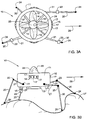
- the basic structure of UMD 10 is constituted by a toroidal duct 11 surrounding a rotor and propeller assembly 12 and a main center body 13. Centerbody 13 is supported within duct 11 by structured elements such as an array of struts 14. This basic structure creates a ducted aerodynamic fan blowing an air stream through the duct which acts to propel the UMD.
- the embodiment of the UMD illustrated herein is highly compact and light weight.
- Duct 11 has a diameter 0.4 meters.
- the gross take-off weight of the UMD is 2 kg (2000 grams).
- the primary structural material for the UMD is KELVAR which has a high strength-to-weight ratio.
- the invention can, of course, be embodied in other robot scout structures having different weights and dimensions.
- Centerbody 13 houses the main engine, the energy source and the electronics compartment containing a computer unit.
- the main rotor engine is an electrical brushless DC motor having 200 wags output power.
- the energy source is constituted by a bank of Lithium batteries. Structure elements 14 fix the centerbody 13 to the duct 11.
- the air mobility capability of the UMD is based essentially on the concept of a ducted fan VTOL air vehicle as described in the Ebbert et. al. U.S. Patent No. 5,295,643.
- a circular array of control vanes 15 mounted within toroidal duct 11 affords the aerodynamic means required to control the flight and attitude of the UMD.
- Fig. 6 which shows the units in the electronics compartment
- Actuation means for flight control include rotor-control 76 and control vane servo actuators 77 for the four vanes.
- the required set of sensors 17 as shown in Fig. 1(a) are assembled in a housing 16 mounted on the exterior of the toroidal duct.
- a communication unit 18 provided with an antenna 19 is mounted on the outer surface of the ducted fan 11.
- Low weight components are preferred for implementing communication unit 18.
- FM receiver model TETRA 301FM commercially available from FMA Direct Inc., weighs only 14 grams and provides the onboard end of the uplink 68 (see Fig. 6).
- a video transmitter model TSG TX commercially available from the Security Group which also weighs only 14 grams, provides the onboard end of the downlink 69.
- Communication unit 18 establishes a two-way wireless data link between UMD 10 and remotely-located operating personnel. It also establishes a two-way wireless data link between UMD 10 and other UMDs in order to coordinate a mission assigned to a group of UMDs.
- a distributed-decentralized architecture is utilized, the details of which are disclosed in Yavnai A., "Distributed Decentralized Architecture for Autonomous Cooperative Operation of Multiple Agent System", in. Proceedings of IEEE Symposium on Autonomous Underwater Vehicle Technology, 19-20 July 1994, Cambridge, pp. 61-67 and Guelman, M., and Yavnai, A., US Patent 5,340,056, 1994.
- Fig. 1(a) illustrates a situation in which the legs are in a retracted state.
- Fig. 1(b) illustrates a situation where the legs are in an extended outstretched position.
- four legs are provided which are similar to those shown in Fig. 1 of U.S. Patent No. 5,842,533 to Takeuchi.
- each leg has two links, namely, an upper link 21 and a lower link 20.
- the kinematic arrangement of the leg's joints and links of the present invention is similar to that shown in Fig. 9 of the Paynter, U.S. Patent No. 5,040,626.
- Upper link 21 is actuated by a double-actuator 22 mounted on the external surface of the duct 11.
- An active joint 23 provides a relative one-degree-of freedom controlled motion between upper link 21 and lower link 20, each lower link 20 having a foot 24.
- the legs also function as landing gear struts, preferably with energy absorbing capability. The legs are capable of compensating for ground irregularities, so that the main body of UMD 10 is kept in a level state.
- a payload housing 25 is mounted on top of centerbody 13 above the rotor assembly. Housing 25 has an optical window 26 to protect the internal electro-optical sensors and associated electronics.
- the main sensor housed in payload housing 25 is a video camera 70 such as a CCD video camera with resolution of 256x256 pixels, such as model SG-2000-CMOS, commercially available from The Security Group, (weighing 5 grams).
- a light emitting unit is aligned with the video camera 70 line-of-sight to facilitate camera operation under low light conditions.
- An infra-red uncooled camera 71 (see Fig. 6) is also included as an. option.
- Payload housing 25 is capable of rotating 360 degrees around an axis which is aligned with the central axis of the centerbody 13 and with the axis of rotation of the rotor. This rotation is effected by a light weight DC servo motor 79.
- a suitable motor for this purpose is DC servo model LS-3.0 commercially available from Wes-Technik, Germany (weight 3 grams).
- the payload includes housing 25 equipped with window 26 for accommodating video camera 70 and possibly also IR camera 71, by another embodiment other payload equipment may be employed in addition or in lieu of the specified video camera and IR camera, depending upon the designated mission(s) of the UMD.
- UMD 10 is capable of operating in several alternative modes.
- UMD 10 is supported by the legs extended therefrom which support the weight of the UMD and also compensate for ground irregularities in order to maintain UMD's main body in a level state.
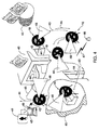
- UMD 10 In a hovering mode 31, UMD 10 is capable of moving in one of three alternate directions: (1) vertical take-off 35; (2) vertical landing 34; and (3) hovering flight 36. It is also capable of hovering above the same ground location in a keep-on-station mode. In cruise dash flying mode 32, UMD 10 then flies in direction 37. In a walking mode 33, UMD 10 then walks on the ground or cimibs stairs in the general direction 38. In a ground mobility mode UMD 10 can creep or otherwise move along the ground using the legs as supporting mechanisms.
- Figs. 3(a) and 3(b) show UMD 10 in an exemplary walking mode.
- Fig. 3(a) being a top view
- Fig. 3(b) a side view
- UMD 10 is shown moving on an uneven terrain 27 in the general direction 28.
- UMD 10 has four legs, each leg being constituted by two interconnected links - the upper link 21 and the lower link 20.
- the upper link 21 is actuated by a double-actuator 22 which is mounted on the external surface of the duct 11.
- the double-actuator 22 provides two one-degrees-of-freedom controlled rotary motions around axes perpendicular to upper link 21.
- each degree-of-freedom of the double-actuator 22 is provided by a light-weight (several grams) rotary DC servo brushless motor such as DC servo model LS-3.0, commercially available from Wes-Technik, Germany (weight 3 grams).
- An active joint 23 provides a relative one-degree-of-freedom controlled rotary motion between upper link 21 and lower link 20.
- the one-degree-of-freedom motion of the active joint 23 of the present embodiment is also provided by a light weight (several grams) rotary DC servo brushless motor such as the above noted DC servo model LS-3.0.
- All three degrees-of-freedom of each leg are rotary, and each one thereof is provided by a one-degree-of-freedom rotary actuator
- the kinematic arrangement of the leg's joints and links of the present invention is by one embodiment similar to that shown in Fig. 9 U.S. Patent No. 5,040,626 to Paynter.
- the double-actuator 22 provides the two rotary motions around axes which are analogous to axis 1 and axis 2 in Fig. 9 of the Paynter patent.
- Actuator 23 provides the rotary motions around an axis which is analogous to axis 3 in the above-noted Fig. 9.
- the total number of active controlled degrees-of-freedom of the walking mechanism in the present embodiment is therefore twelve.
- Each lower link 20 has a foot 24.
- the foot can be either fixed to the lower link 20, or can be linked to the lower link 20 via a pivot or via a passive elastic energy absorbing element such as a spring, or a combination thereof.
- the legs also function as landing gear struts, preferably with energy absorbing capability. The legs are capable of compensating for ground irregularities to keep the main body level.
- UMD 10 When UMD 10 is walking in general direction 28, a plurality of sensors are activated in order to determine its geographical location; the geometrical features of the surrounding environment; its position relative to other objects; and any obstacles in its way.
- the plurality of sensors 17 which encompass a 360 degrees field of view satisfies these needs. Also supporting these needs are the electro-optical sensors housed in payload housing 25, these being directed forward through optical window 26 which is capable of rotating 360 degrees around its main axis.
- Path planning techniques employed in the present embodiment are based, e.g. on techniques described in the following references: a) A system for obstacle avoidance and path planning disclosed in U.S. Patent No. 5,502,638 to Takenaka b) "Motion Planning of Walking Robots in Environments with Uncertainty", Chen et. al., Journal of Robotic Systems, John Wiley & Sons, Inc., Volume 16, No.10, pp. 527-545, 1999.
- the problem of indoor navigation falls into two categories; namely navigating with an a-priori map or database; and navigating without this map or database.
- the navigation function uses a-prior data about the building layout, by employing appropriate LFMs - local feature maps (see Figs. 8(a) and 8(b)). If an a-priori map is not available or if the object 54 to be visited has been damaged so that the a-priori map is no longer a true representation of the actual object, then a different navigation procedure is executed, the so-called "navigating in a maze”. A process called "map building" is then a part of the navigation process.
- a CCD camera with a resolution of 256x256 pixies is only 5 grams in weight, (Model SG-2000-CMOS, commercially available from The Security Group)
- acoustic sensors which weigh only 5 grams each, or infra-red LED-based range finders which weigh only 5 grams each.
- Fig. 4 illustrated therein is a typical, yet not exclusive, scenario of a UMD executing a data gathering and situation-monitoring mission within a disaster site.
- An operator 40 is put in charge of operating UMD 10 and of supervising its operation from a safe location, preferably in the vicinity of the disaster area.
- operator 40 When arriving at the station from which to launch UMD 10 on its scouting mission and to thereafter manage its operation, operator 40 then has the following series of pre-mission activities to undertake: a) unpack UMD 10 from its protective packaging; b) place UMD 10 on an uncluttered surface for safe take-off and landing; c) press a key on the command and control portable unit keyboard in order to transmit an ON command (see OnCmd 99 in Fig. 7) so as to "Wake-Up' UMD 10 and change its state from System. Non-Active state 89 to System Preparing state 90.
- a Built-In-Testing ("BIT") is automatically initiated; d) using the command and control portable unit 41 to edit a mission; e) press a key on the command and control portable unit keyboard in order to download the mission plan file to UMD 10 via wireless data link 42.
- BIT Built-In-Testing
- UMD 10 When this pre-mission series of activities is completed, UMD 10 is now ready for its mission. It is important that the pre-mission procedure be accelerated to enable a fast reaction to a disaster situation. Thus, the mission edition activity, the most time consuming activity of all pre-mission activities, is designed to be as rapid and as simple as possible.
- the mission editing display is shown in Fig. 5.
- operator 40 uses a command and control portable unit 41 to edit a mission plan and to control operation of UMD 10 while on its mission.
- a wireless communication unit 49 is connected to the command and control portable unit 42, thereby establishing a two-way data link with UMD 10 and with self-contained unattended sensor means 46, if these are deployed by UMD 10.
- a mission plan After a mission plan is edited and generated, it is transmitted and downloaded to UMD 10 via wireless data link 42. While in operation, operator 40 may transmit orders to UMD 10 and receive data from it via data link 42.
- UMD 10 is travelling along the planned path 43 in the general direction 44. And in a manner appropriate to the situation, UMD 10 is moving in various alternate modes, as described in connection with Fig. 2.
- UMD 10 is moving either outside or inside a burning building 45.
- the navigation function uses a-priori data about the building layout, by employing the appropriate LFMs - local feature maps (see Figs. 8(a) and 8(b)).
- LFMs - local feature maps see Figs. 8(a) and 8(b)
- UMD 10 can land vertically, stand for a while on a supporting surface, take-off vertically, and then hover over the site. This sequence of movements can be repeated when necessary.
- the electro-optical sensor housed in payload housing 25 has a field-of-view 48 which is directed forward in the direction of movement or toward an area of interest.
- Other sensors which constitute payload whose activation depends on the specific situation may include a microphone 72, a smoke detector 73 and a gas detector 74. It may also be desirable to include a seismograph to sense earth tremors.
- UMD 10 when landing vertically, can then deploy by using a device release actuator 80, self-contained unattended sensor means 46 for further data gathering in the disaster area.
- Sensor means 46 which may be situated on various supporting surfaces such as on the ground transmits data it gathers to communication unit 49 attached to the command and control portable unit 41 via a wireless data link 47.
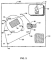
- FIG. 5 Shown in Fig. 5 is an overhead view of display 50 of the command and control portable unit 41 in accordance with one embodiment of the invention.
- Display 50 comprises a video display window 51, as well as an alphanumeric display window 53.
- the largest area of the display is then used for the graphical symbolic representation of the main elements of the mission plan.
- two objects 54 in the disaster site have to be monitored.
- Operator 40 edits a mission plan consists by this embodiment of the following elements: a) a mission starting and terminating location ST 55; b) a travelling route represented by an ordered series of way-points, WP 56, connected by route segments 58. In the example shown in Fig.5, there are seven way-points WP 56 designated WP1 to WP7 by the order they are planned to travel. Each WP 56 represents a specific location; c) a series of ordered device deployment locations DD 57.
- DD 57 points there are two DD 57 points, DD1 and DD2; d) a return segment 59 which connects the last way-point WP7 to the terminal point 55; e) an indoor travelling segment inside an object to be monitored, this segment being between WP5 and WP6.
- the command and control portable unit 41 has a data base of the LFMs, (see Figs. 8(a) and 8(b)) of objects in the disaster area. This data base is downloaded and stored in the command and control portable unit 41 before going to the disaster area.
- the functional architecture of the electronics unit is of the "Bus Network Topology" type.
- Computer unit 60 is connected to all of the associated elements via a local area network -LAN 61.
- Computer unit 60 is provided with processing elements, memory elements, and I/O elements and whatever other elements are desirable to execute all of the required computations, such as: a) flight control; b) navigation; c) sensor data processing; d) multi-legged control; e) path planning and obstacle avoidance.
- a set of three piezoelectric gyros 62 are used to measure the angular rate about three perpendicular axes which together establish a right-handed orthonormal coordinate system.
- GPS receiver 63 provides location and velocity navigational information
- a magnetometer 64 provides directional data with respect to the geomagnetic field which is in turn related to the geographic coordinate system and thus provides approximated azimuth information.
- a set of piezoelectric tilt sensors 65 serve to determine the attitude of the UMD 10 with respect to the gravity vector.
- IR infra-red
- LED light emitting diodes
- rangefinders 66 to effect short range distance measurements (effective up to about 10 meters) to surrounding objects. These measurements provide crucial data for positioning, navigating and obstacle avoidance when UMD 10 is moving in its ground mobility mode.
- each rangefinder 66 weighs only 5 grams.
- a plurality of acoustic rangefinders 67 are also used for measuring distance to the surrounding objects. The addition of acoustic rangefinders 67 affords more comprehensive coverage than when using only IR-LED rangefinders 66.
- the two-way wireless data link of the robot scout is preferably a radio-frequency RF data link. It comprises a RF uplink 68 for communicating data to UMD 10, and an RF downlink 69 for communicating data, including video data, from the UMD.
- a commercially-available receiver for this purpose may weigh as little as 12 grams for a range of over 2 kilometers.
- a commercially-available video transmitter may weigh as little as 14 grams for a range of over 4 kilometers, providing that a line-of-sight exists between the transmitter and receiver.
- a video camera 70 serves to provide: a) a close-up viewing of the disaster site which can be displayed to remote operator 40; b) a visual sensor for visual positioning, navigation and obstacle avoidance. Similar arrangements are described in: a) Movarec, Hans P., "Robot Rover Visual Navigation", UMI Research Press, Ann Arbor, Michigan,1981, pp. 49-147; b) Robert, Luc, et. al., "Applications of Non-Metric Vision to Some Visually Guided Robotic Tasks", in Aloimonos, Yiannis, ed., "Visual Navigation- From Biological Systems to Unmanned Ground Vehicles", Lawrence Erlbaum Associates Publishers, Mahwah, New Jersey, 1997, pp.
- flood lights may be added to the UMD in order to provide acceptable light conditions for the camera, especially in indoor situations.
- An uncooled infra-red camera 71 may be used for poor light situations, as well as a hot spot detector.
- microphones 72 For situation monitoring missions, such as for finding missing people in ruined buildings use may be made of microphones 72. Acoustic signals received by the microphones 72 are conveyed to operator 40 at the remote station via the RF downlink 69.
- a smoke detector 73 provides means to detect sources of smoke and smoke-generating situations.
- a gas detector 74 serves to detect gas contamination, especially in areas of high and dangerous gas concentration.
- the legs of UMD 10 may be equipped with leg load sensors 75 for controlling the multi-legged walking. As an alternative, measuring the current at the leg servo motors may provide the necessary control information.
- a rotor control function 76 provides the command signals necessary to control rotor motion.
- a vane servo actuators function 77 provides the command signals to control vanes 15.
- a leg servo actuators function 78 provides the command signals for the plurality of leg actuators.
- a sensor payload servo actuator 79 provides the command signals to control the payload servo.
- a device release actuator 80 is used to produce the command signal to the device release actuator when unattended sensor means 46 has to be deployed.
- Power supply 81 supplies all of the electrical power consumed by all onboard units. For this purpose use may be made of a bank of Lithium batteries.
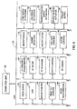
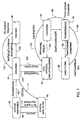
- Fig. 7 is a diagram state graph notation of the main operational and mobility modes of UMD 10 and of the transitions between these modes, in accordance with one embodiment of the invention.
- a notation of state is assigned to each mobility mode, as well as to start and standing situations.
- the following states constitute, by this embodiment, the state graph: a) system non-active 89; b) system preparing 90; c) standing 91; d) VTOL- vertical take-off/landing 92; e) hovering 93; f) transitioning 94; g) dash flying 95; h) walking 96.
- states 92 through 95 are air mobility states and State 96 is a ground mobility state.
- the power Prior to the mission, and after completing the mission, the power is preferably off, and UMD 10 is then in its system non-active state.
- OnCmd 99 Upon receiving an On command OnCmd 99 from operator 40 via the data link, the state of UMD 10 is transitioned to system preparing state 90.
- system preparing state 90 On entering the system preparing state 90, a Built-In-Testing ("BIT") procedure is automatically initiated. If the BIT result is OK, and the mission plan has been downloaded correctly, the condition SystemReady 100 is logically TRUE, and the state of UMD 10 is transitioned to standing state 91. But if the BIT procedure failed, BITFailed condition 112 is TRUE. Or in case operator 40 sends a mission abort command AbortCmd 112, the state of UMD 10 is transitioned to system non-active state 89 and the UMD 10 power is off.
- BIT Built-In-Testing
- UMD 10 when in the standing state 91 may be in a waiting situation, in a data gathering situation, or in a sensor means 46 deploying situation, or in a combination of these situations.
- UMD 10 Upon receiving a TakeOffCmd 101, UMD 10 is transitioned from standing state 91 to VTOL state 92, starting to take-off. If flying conditions do not exist, the UMD is either in a staying or standing state 91 or is transitioned to walking state 96.
- condition TouchDown 108 is TRUE, and the UMD 10 is transitioned to standing state 91.
- the transition from an air mobility mode to a ground mobility mode and vice versa is always carried out by first going to standing state 91, and thereafter to the desired mobility mode, either ground or air.
- the WalkingCmd 109 is issued either by remote operator 40, or internally by the UMD mission controller.
- AtLocation condition 110 is TRUE or stop command StopCmd 110 is issued either by remote operator 40 or internally by the UMD mission controller.
- StopCmd 110 is issued either by remote operator 40 or internally by the UMD mission controller.
- a situation which is typical for the internal issuance of a StopCmd 110 is when UMD 10 encounters a large obstacle while walking.
- OffCmd 111 When UMD 10 is in standing state 91, an off command OffCmd 111 will transit the UMD 10 state from standing state 91 to system non-active state 89, and UMD 10 power will shut-off. OffCmd 111 is issued either internally by the UMD 10 mission controller or by the remote operator 40. Upon completing the mission, OffCmd 111 is usually issued internally.
- Fig. 8(a) shows the layout of a building interior section
- Fig. 8(b) is its associated graph-based data structure representation (according to one possible variant), termed Local Feature Map -LFM.
- Fig. 8(a) is a layout of a building section consisting of: a) two corridors C1-121 and C2-122; b) a corner CR12 120 which connects the two corridors; c) four rooms R1 123, R2 124, R3 125, and R4 126 which are accessed from the corridors through openings; d) the following openings: O1 127 between corridor C1 121 and room R1 123; 02 128 between corridor C1 121 and room R2 124; 031 and 032 both between corridor C2 122 and room R3 125; 04 131 between corridor C2 122 and room R4 126.
- Fig. 8(b) is an example of the associated Local Feature Map ⁇ LFM which is used in the present embodiment to represent the essential features of the building section layout.
- the data structure which is used to represent the LFM is a non-directional graph (See Even, S., "Graph Algorithms", Computer Science Press, Maryland, USA, 1979, for more details on non-directional graphs).
- the root node of the graph is the corner CR12 140. It has two associated daughter nodes, corridor C1 node 141 and corridor C2 node 142.
- the connecting arcs 147 and 148 symbolizes the connection between the comer CR12 and its connected corridors C1 and C2.
- Corridor C1 node 141 has two associated daughter nodes namely, room. R1 node 143 and room R2 node 144.
- the connecting arcs 149 and 150 symbolize the associated openings O1 149 and 02 150 respectively.
- corridor C2 node 142 has two associated daughter nodes namely, room R3 node 145 and room R4 node 146.
- the connecting arcs 151, 152 and 153 symbolizes the associated openings 031 151 and 032 152 and 04 153, respectively.
- the associated LFMs can be prepared in advance. It should be noted however, that although an LFM is possibly prepared a-priori, during a major disaster, such as an earthquake, so many changes may occur that the original LFM may no longer represent the actual layout.
Abstract
Description
- This invention relates generally to remotely-controlled unmanned mobile devices adapted to function as a robot scout to gather information regarding conditions prevailing at a disaster site and to communicate this information to a rescue mission.
- In disaster situations, the availability of timely and accurate information regarding conditions prevailing at the site of the disaster may be crucial to the success of a rescue mission. Typical, yet not exclusive, of such situations are an explosion at a chemical manufacturing facility, the leakage of hazardous materials at an urban site, a nuclear reactor accident or an earthquake as well as other serious ecological and natural catastrophes.
- Should a rescue mission seek to gain advance information regarding conditions prevailing in the region of a disaster so that the mission can decide on appropriate rescue procedures, in many cases this attempt may expose scouts assigned to this task to life-threatening risks. For example, if the disaster area is the site of a nuclear reactor accident in which released into the area are lethal radioactive particles, scouts would be ill advised to enier this area.
- The present invention resides in a remotely-controlled unmanned mobile device (UMD) functioning as a robot scout adapted to enter and reconnoiter a disaster site in behalf of a rescue mission to gather information in regard to conditions prevailing at the site and to communicate this information to the mission. The UMD is operable either in an air-mobility mode or in a ground-mobility mode, so that it is capable of fully exploring the site. While conditions prevailing at the site of a disaster may threaten the life of a living scout, they can do no injury to a robot scout.
- Because in its air-mobility mode the UMD operates in a manner similar to that of a vertical take-off and landing vehicle (VTOL), of prior art interest in this regard is the unmanned VTOL air vehicle described e.g. in U.S. Patent No. 5,295,643 to Ebbert et al. This device is capable of vertical take-off and landing in confined areas. It is also capable of transition to horizontal high speed flight and is able to hover and loiter for a period of time. The vehicle includes coaxial forward and aft centerbodies, and a ducted rotor having a plurality of propellers. The ducted fan is aerodynamically efficient and is safe because of its unexposed rotor blades.
- And since a UMD in accordance with the invention when operating in a ground mobility mode can walk on the terrain of the disaster site, however difficult the terrain, of prior art interest is the multi-legged walking robot disclosed c.g. by Takeuchi in U.S. Patent No. 5,842,533. This device is capable of walking on uneven ground while carrying a payload. This multi-legged walking robot provides some of the basic capabilities for the ground mobility portion of a dual-mode UMD device in accordance with the invention.
- In the six-legged walking robot described by Paynter in U.S. Patent No. 5,040,626, each leg, composed of two links, has three controlled degrees-of-freedom of rotary motion. This device is also capable of walking on uneven ground and carrying a payload.
- Obstacle avoidance and indoor navigation capability is needed in order to execute the mission of a robot scout in a disturbed environment. A system for obstacle avoidance and path planning is disclosed by Takenaka in U.S. Patent No. 5,502,638. A survey of sensors and techniques appropriate for indoor positioning is set forth in Borenstein, J., et. al., "Mobile Robot Positioning - Sensors and Techniques", The Journal of Robotic Systems, Vol. 14, No. 4, 1997, pp. 231-249, and in Borenstein, J., et. Al., "Navigating Mobile Robots: Sensors and Techniques", A.K. Peters Ltd., Wellesley, MA., 1995.
- Of prior art background interest regarding ducted fan VTOL devices, walking robots, distributed decentralized command and control of multiple mobile devices, as well as a unit for command control of mobile devices are the following U.S. patents:
- Patent 5,295,643 (1994) ― ducted fan VTOL
- Patent 5,842,533 (1998) ― legged robot
- Patent 5,040,626 (1991) ― legged robot
- Patent 5,502,638 (1996) ― path planning and obstacle avoidance
- Patent 5,340,056 (1994) ― Active defense system - cooperative
- Operation of multiple UAVs (distributed-decentralized command and control of multiple unmanned devices).
-
- Also of prior art interest in regard to various features included in a UMD robot scout in accordance with the invention are the following publications:
- Chen, Chun-Hung et. al., "Motion Planning of Walking Robots in Environments
with Uncertainty", Journal of Robotic Systems, John Wiley & Sons, Inc.,
Volume 16, No.10, 1999 , pp. 527-545. - Todd, D.J., "Walking Machines- An Introduction to Legged Robots", Kogan Page Ltd., London U.K., 1985, pp. 63-168.
- Movarec, Hans P., "Robot Rover Visual Navigation", UMI Research Press, Arm Arbor, Michigan, 1981, pp. 49-147.
- Thorpe, Charles E., ed., "Vision and Navigation", Kluwer Academic Publishers, Norwell MA., 1990, pp.
- Robert, Luc, et. al., "Applications of Non-Metric Vision to Some Visually Guided Robotic Tasks", in Aloimonos, Yiannis, ed., "Visual Navigation- From Biological Systems to Unmanned Ground Vehicles", Lawrence Erlbaum
- Associates Publishers, Mahwah, New Jersey, 1997, pp. 89-134.
- Wcng, J. J., et. al.,"Visual Navigation Using Fast Content-Based Retrieval", in Aloimonos, Yiannis, ed., "Visual Navigation- From Biological Systems to Unmanned Ground Vehicles", Lawrence Erlbaum Associates Publishers, Mahwah, New Jersey, 1997, pp. 178-217.
- Dean, Thomas, et. al., " Planning and Navigation in. Stochastic Environments", in Aloimonos, Yiannis, ed., "Visual Navigation- From Biological Systems to Unmanned Ground Vehicles", Lawrence Erlbaum Associates Publishers, Mahwah, New Jersey, 1997, pp., 251-274.
- Adams, Martin David, "Sensor Modeling, Design and Data Processing for Autonomous Navigation", World Scientific Publishers, Singapore, 1999, pp. 153-208.
- Song, Shin-Min, et. al., "Machines That Walk", The MIT Press, Cambridge, MA, 1989, pp.23-281.
- Fahlstrom, Paul G., et. al., "Introduction to UAV Systems", UAV Systems Inc., Columbia, Maryland, 1993, pp. II 42- II 47.
- Kohlman, David L., "Introduction to V/STOL Airplanes", Iowa State University Press, Ames, Iowa, 1981.
- Yavnai A., "Distributed Decentralized Architecture for Autonomous Cooperative Operation of Multiple Agent System", in Proceedings of IEEE Symposium on Autonomous Underwater Vehicle Technology, 19- 20 July 1994, Cambridge, pp. 61-67.
- Arlowc, H.D., "Airborne Remote Operated Device", Proceedings of the 15th Annual Technical Symposium of the Association of Unmanned Vehicle Systems, San-Diego, CA., June 6-8, 1988, pp. 1-13.
- Borenstein, J., et. al., Mobile Robot Positioning - Sensors and Techniques", The Journal of Robotic Systems, Vol. 14, No. 4, 1997, pp. 231-249.
- Borenstein, J., et. al., "Navigating Mobile Robots: Sensors and Techniques", A.K. Peters Ltd., Wellesley, MA., 1995.
- Even, S., "Graph Algorithms", Computer Science Press, Maryland, USA, 1979.
-
- In view of the foregoing, the main object of this invention is to provide a remotely-controlled unmanned mobile device (UMD) adapted to function as a robot scout in behalf of a rescue mission to enter and reconnoiter the site of a disaster, to gather information regarding conditions prevailing at this site and to communicate this information to the mission which can then decide on rescue actions appropriate to the prevailing conditions. The UMD may be adapted to additional functions, all as required and appropriate.
- More particularly an object of this invention is to provide a dual mobility UMD which is operable either in an air mobility mode or in a ground mobility mode, making it possible for the robot scout to fully explore the disaster site.
- Among the significant advantages of a UMD robot scout according to the invention are the following:
- A. The UMD can fly from a nearby safe station to the disaster area and reconnoiter the area to gather information regarding the conditions which prevail in the area, which information is conveyed to rescue mission personnel who are exposed to no risk in gathering the information.
- B. When the UMD arrives at a disaster area, its on-board sensors then proceed to collect the information required by the rescue mission, which information is communicated to rescue mission personnel who are thereby advised of possible dangers they may encounter when entering the disaster area and can then take steps to avoid these dangers.
- C. In its ground mobility mode, the UMD can traverse difficult terrain and walk through wrecked structures and ruins in order to reconnoiter the entire site.
- D. When several UMD's are enlisted by a rescue mission to reconnoiter a disaster area, they can communicate with each other to coordinate their activity.
- E. The UMD is compact in form and light in weight, being composed mainly of miniature components.
- F. The UMD should preferably be equipped with payload, which can be activated whenever required.
-
- Briefly stated, these objects are accomplished in a remotely-controlled unmanned mobile device (UMD) adapted to function as a robot scout to enter and reconnoiter the site of a disaster and to communicate to a rescue mission information regarding conditions prevailing at the site, making it possible for the mission to decide on rescue measures appropriate to these conditions.
- The UMD is operable in either of two modes. In its air-mobility mode, the UMD is able to vertically take off and land, to fly to the site and then hover thereover. In its ground-mobility mode, the UMD can walk on its legs over difficult terrain and through wrecked structures and ruins. The UMD is provided with condition-sensing detectors for gathering data regarding conditions prevailing at the site, and position-sensing sensors for avoiding obstacles in the path of the walking UMD, thereby assuring safe mobility. Other sensors govern. geo-referenced navigational and flight control functions.
- For a better understanding of the invention as well as other objects and features thereof, reference is made to the annexed drawing wherein:
- Figs. 1(a) and 1(b) are perspective views of an unmanned mobile vehicle in accordance with a preferred embodiment of the invention; Fig. 1(a) showing the device when its legs are retracted, Fig. 1(b) showing the same device with its legs extended;
- Fig. 2 is a perspective view of the unmanned mobile device in alternative mobility modes;
- Figs. 3(a) and 3(b) are top and side views, respectively, of the unmanned mobile device in an all-terrain walking mode;
- Fig. 4 is a perspective view of the unmanned mobile device in a typical data gathering and situation-monitoring scenario in a disaster area;
- Fig. 5 is an overhead view of the display of the command and control portable unit;
- Fig. 6 is a functional diagram of the electronics unit architecture;
- Fig. 7 is a diagram of the main operational and mobility modes and the associated inter-mode transition logic; and
- Figs. 8(a) and 8(b) are layouts of a building interior and its associated graph-based data structure representation.
-
- Whilst for connivance of explanation, the description focuses mainly in UMD that is utilized by rescue forces in disaster areas, those versed in the art will readily appreciate that the UMD of the invention is by no means bound by this application. Accordingly, the UMD of the invention may be utilized by an operator or operators in any area of interest.
- The UMD: A UMD in accordance with the invention is adapted to function as a robot scout to reconnoiter a disaster area. As shown in Figs. 1(a) and 1(b), the basic structure of
UMD 10 is constituted by atoroidal duct 11 surrounding a rotor andpropeller assembly 12 and amain center body 13.Centerbody 13 is supported withinduct 11 by structured elements such as an array ofstruts 14. This basic structure creates a ducted aerodynamic fan blowing an air stream through the duct which acts to propel the UMD. - The embodiment of the UMD illustrated herein is highly compact and light weight.
Duct 11 has a diameter 0.4 meters. The gross take-off weight of the UMD is 2 kg (2000 grams). The primary structural material for the UMD is KELVAR which has a high strength-to-weight ratio. The invention can, of course, be embodied in other robot scout structures having different weights and dimensions. -
Centerbody 13 houses the main engine, the energy source and the electronics compartment containing a computer unit. In the present embodiment, the main rotor engine is an electrical brushless DC motor having 200 wags output power. The energy source is constituted by a bank of Lithium batteries.Structure elements 14 fix thecenterbody 13 to theduct 11. - The air mobility capability of the UMD is based essentially on the concept of a ducted fan VTOL air vehicle as described in the Ebbert et. al. U.S. Patent No. 5,295,643. A circular array of
control vanes 15 mounted withintoroidal duct 11 affords the aerodynamic means required to control the flight and attitude of the UMD. - In operation, when the driven propellers in the ducted fan rotate to blow an air stream in the downward vertical direction, this provides the UMD with the necessary lift forces. To cause the UMD to descend vertically toward the ground, the rotor speed is reduced. The legs of the UMD are then outstretched to function as landing gear. Upon landing at a disaster site or elsewhere, the legs function to maintain the robot erect and as a walking mechanism.
- When the UMD is aloft, its flight direction is controlled by the four
vanes 15 which intercept the air stream being blown out of the duct to produce a lateral force causing the UMD to fly in the North, South, East or West direction depending on the angular position of the four vanes in die circular array shown in Fig. 1(a). - To support the geo-navigation and flight control functions of the UMD, several sensors are required for this purpose. These include (see Fig. 6 which shows the units in the electronics compartment) the following:
- (a) Three piezoelectric gyros 62 (such as Piezo gyro model HMX M1010, commercially available from HELI-MAX which weighs only 13 grams)
- (b)
GPS receiver 63 - (c)
3D Magnetometer 64 - (d) Two
piezoelectric tilt sensors 65. -
- Actuation means for flight control include rotor-
control 76 and controlvane servo actuators 77 for the four vanes. The required set ofsensors 17 as shown in Fig. 1(a) are assembled in ahousing 16 mounted on the exterior of the toroidal duct. - A
communication unit 18 provided with anantenna 19 is mounted on the outer surface of theducted fan 11. Low weight components are preferred for implementingcommunication unit 18. For example FM receiver model TETRA 301FM, commercially available from FMA Direct Inc., weighs only 14 grams and provides the onboard end of the uplink 68 (see Fig. 6). A video transmitter model TSG TX, commercially available from the Security Group which also weighs only 14 grams, provides the onboard end of thedownlink 69. -
Communication unit 18 establishes a two-way wireless data link betweenUMD 10 and remotely-located operating personnel. It also establishes a two-way wireless data link betweenUMD 10 and other UMDs in order to coordinate a mission assigned to a group of UMDs. - Those versed in the art will readily appreciate that the invention is by no mean bound by the specific structure of the UMD in accordance with Figs. 1(a) and 1(b), and by the same token it is not bound by the system architecture, described with reference to Fig. 6.
- Various approaches have heretofore been proposed to solve the problem of command and control of multiple unmanned mobile systems. In accordance with a preferred embodiment, a distributed-decentralized architecture is utilized, the details of which are disclosed in Yavnai A., "Distributed Decentralized Architecture for Autonomous Cooperative Operation of Multiple Agent System", in. Proceedings of IEEE Symposium on Autonomous Underwater Vehicle Technology, 19-20 July 1994, Cambridge, pp. 61-67 and Guelman, M., and Yavnai, A., US Patent 5,340,056, 1994.
- The all-terrain ground mobility of the scouting device is achieved by using active multiple mechanical legs to support the UMD and cause it to walk on the terrain of the disaster site. Fig. 1(a) illustrates a situation in which the legs are in a retracted state. Fig. 1(b) illustrates a situation where the legs are in an extended outstretched position. In the present embodiment four legs are provided which are similar to those shown in Fig. 1 of U.S. Patent No. 5,842,533 to Takeuchi.
- In the present embodiment, each leg has two links, namely, an
upper link 21 and alower link 20. The kinematic arrangement of the leg's joints and links of the present invention is similar to that shown in Fig. 9 of the Paynter, U.S. Patent No. 5,040,626.Upper link 21 is actuated by a double-actuator 22 mounted on the external surface of theduct 11. An active joint 23 provides a relative one-degree-of freedom controlled motion betweenupper link 21 andlower link 20, eachlower link 20 having afoot 24. The legs also function as landing gear struts, preferably with energy absorbing capability. The legs are capable of compensating for ground irregularities, so that the main body ofUMD 10 is kept in a level state. - A
payload housing 25 is mounted on top ofcenterbody 13 above the rotor assembly.Housing 25 has anoptical window 26 to protect the internal electro-optical sensors and associated electronics. The main sensor housed inpayload housing 25 is avideo camera 70 such as a CCD video camera with resolution of 256x256 pixels, such as model SG-2000-CMOS, commercially available from The Security Group, (weighing 5 grams). A light emitting unit is aligned with thevideo camera 70 line-of-sight to facilitate camera operation under low light conditions. An infra-red uncooled camera 71 (see Fig. 6) is also included as an. option.Payload housing 25 is capable of rotating 360 degrees around an axis which is aligned with the central axis of thecenterbody 13 and with the axis of rotation of the rotor. This rotation is effected by a light weightDC servo motor 79. A suitable motor for this purpose is DC servo model LS-3.0 commercially available from Wes-Technik, Germany (weight 3 grams). - Whilst in the example above the payload includes
housing 25 equipped withwindow 26 for accommodatingvideo camera 70 and possibly alsoIR camera 71, by another embodiment other payload equipment may be employed in addition or in lieu of the specified video camera and IR camera, depending upon the designated mission(s) of the UMD. - Turning now to Fig. 2,
UMD 10 is capable of operating in several alternative modes. In a standingmode 30,UMD 10 is supported by the legs extended therefrom which support the weight of the UMD and also compensate for ground irregularities in order to maintain UMD's main body in a level state. - In a hovering
mode 31,UMD 10 is capable of moving in one of three alternate directions: (1) vertical take-off 35; (2)vertical landing 34; and (3) hoveringflight 36. It is also capable of hovering above the same ground location in a keep-on-station mode. In cruisedash flying mode 32,UMD 10 then flies indirection 37. In a walkingmode 33,UMD 10 then walks on the ground or cimibs stairs in thegeneral direction 38. In a groundmobility mode UMD 10 can creep or otherwise move along the ground using the legs as supporting mechanisms. - Figs. 3(a) and 3(b) show
UMD 10 in an exemplary walking mode. Fig. 3(a) being a top view and Fig. 3(b) a side view,UMD 10 is shown moving on anuneven terrain 27 in thegeneral direction 28. In the present embodiment,UMD 10 has four legs, each leg being constituted by two interconnected links - theupper link 21 and thelower link 20. Theupper link 21 is actuated by a double-actuator 22 which is mounted on the external surface of theduct 11. The double-actuator 22 provides two one-degrees-of-freedom controlled rotary motions around axes perpendicular toupper link 21. - In the present embodiment, each degree-of-freedom of the double-
actuator 22 is provided by a light-weight (several grams) rotary DC servo brushless motor such as DC servo model LS-3.0, commercially available from Wes-Technik, Germany (weight 3 grams). An active joint 23 provides a relative one-degree-of-freedom controlled rotary motion betweenupper link 21 andlower link 20. The one-degree-of-freedom motion of the active joint 23 of the present embodiment is also provided by a light weight (several grams) rotary DC servo brushless motor such as the above noted DC servo model LS-3.0. - All three degrees-of-freedom of each leg are rotary, and each one thereof is provided by a one-degree-of-freedom rotary actuator, The kinematic arrangement of the leg's joints and links of the present invention is by one embodiment similar to that shown in Fig. 9 U.S. Patent No. 5,040,626 to Paynter. The double-
actuator 22 provides the two rotary motions around axes which are analogous to axis 1 and axis 2 in Fig. 9 of the Paynter patent.Actuator 23 provides the rotary motions around an axis which is analogous to axis 3 in the above-noted Fig. 9. The total number of active controlled degrees-of-freedom of the walking mechanism in the present embodiment is therefore twelve. Eachlower link 20 has afoot 24. The foot can be either fixed to thelower link 20, or can be linked to thelower link 20 via a pivot or via a passive elastic energy absorbing element such as a spring, or a combination thereof. The legs also function as landing gear struts, preferably with energy absorbing capability. The legs are capable of compensating for ground irregularities to keep the main body level. - Automatic control of legged locomotion is necessary in. order to exploit the all-terrain mobility of the UMD. It is particularly required in a disrupted terrain or environment, such as when ruined buildings are encountered by the UMD. This capability raises relatively complex control problems. For example, in the present embodiment up to as many as twelve degrees-of-freedom must be controlled simultaneously. Thus, the control system is called upon to issue as many as twelve coordinated commands to the actuators, (e.g., to DC servo motors) simultaneously, in real time.
- Some of the principles of controlling the multi-legged walking mechanisms in the present embodiment are based on techniques described in the following publications: a) Todd, D.J., "Walking Machines- An Introduction to Legged Robots", Kogan Page Ltd., London U.K., 1985, pp. 91-150; b) Song, Shin-Min, et. al., "Machines That Walk", The MIT Press, Cambridge, MA, 1989, pp.23-164; c) Chen, Chun-Hung et. al., "Motion Planning of Walking Robots in Environments with Uncertainty", Journal of Robotic Systems, John Wiley & Sons, Inc.,
Volume 16, No.10, pp. 527-545, 1999. The invention is, of course, not bound by these techniques. - When
UMD 10 is walking ingeneral direction 28, a plurality of sensors are activated in order to determine its geographical location; the geometrical features of the surrounding environment; its position relative to other objects; and any obstacles in its way. The plurality ofsensors 17 which encompass a 360 degrees field of view satisfies these needs. Also supporting these needs are the electro-optical sensors housed inpayload housing 25, these being directed forward throughoptical window 26 which is capable of rotating 360 degrees around its main axis. - Some of the sensing devices and techniques used in the present embodiment are disclosed in: a) Borenstein, J., et. al., " Mobile Robot Positioning - Sensors and Techniques", The Journal of Robotic Systems, Vol. 14, No. 4, 1997, pp. 231-249; b) Borenstein, J., et. al., "Navigating Mobile Robots: Sensors and Techniques", A.K. Peters Ltd., Wellesley, MA., 1995; c) Adams, Martin David, "Sensor Modeling, Design and Data Processing for Autonomous Navigation", World Scientific Publishers, Singapore, 1999, pp. 153-208. The invention is, of course, not bound by these techniques.
- It is known to use computer-controlled visual techniques for navigation and for obstacle detection and avoidance. Some of the visual devices and techniques for this purpose include the present embodiment, and are described in: a) Movarec, Hans P., "Robot Rover Visual Navigation", UMI Research Press, Ann Arbor, Michigan, 1981, pp. 49-147; b) Robert, Luc, ct. al., "Applications of Non-Metric Vision to Some Visually Guided Robotic Tasks", in Aloimonos, Yiannis, ed., "Visual Navigation- From Biological Systems to Unmanned Ground Vehicles", Lawrence Erlbaum Associates Publishers, Mahwah, New Jersey, 1997, pp. 89-134; c) Weng, J. J., et. al.,"Visual Navigation Using Fast Content-Based Retrieval", in Aloimonos, Yiannis, cd., "Visual Navigation- From Biological Systems to Unmanned Ground Vehicles", Lawrence Erlbaum Associates Publishers, Mahwah, New Jersey, 1997, pp. 178-217; d) Dean, Thomas, et. al., " Planning and Navigation in Stochastic Environments", in Aloimonos, Yiannis, ed., "Visual Navigation- From Biological Systems to Unmanned Ground Vehicles". Lawrence Erlbaum Associates Publishers, Mahwah, New Jersey, 1997, pp., 251-274. The invention is, of course, not bound by these techniques.
- Path planning techniques employed in the present embodiment are based, e.g. on techniques described in the following references: a) A system for obstacle avoidance and path planning disclosed in U.S. Patent No. 5,502,638 to Takenaka b) "Motion Planning of Walking Robots in Environments with Uncertainty", Chen et. al., Journal of Robotic Systems, John Wiley & Sons, Inc.,
Volume 16, No.10, pp. 527-545, 1999. - The problem of indoor navigation falls into two categories; namely navigating with an a-priori map or database; and navigating without this map or database. Where an a-priori map is available, the navigation function uses a-prior data about the building layout, by employing appropriate LFMs - local feature maps (see Figs. 8(a) and 8(b)). If an a-priori map is not available or if the
object 54 to be visited has been damaged so that the a-priori map is no longer a true representation of the actual object, then a different navigation procedure is executed, the so-called "navigating in a maze". A process called "map building" is then a part of the navigation process. - In order to meet the requirements for a highly compact and light weight UMD, use is made in the present embodiment of miniature light weight sensors. For example, a CCD camera with a resolution of 256x256 pixies is only 5 grams in weight, (Model SG-2000-CMOS, commercially available from The Security Group) Also usable are acoustic sensors which weigh only 5 grams each, or infra-red LED-based range finders which weigh only 5 grams each.
- Scenario: Referring now to Fig. 4 illustrated therein is a typical, yet not exclusive, scenario of a UMD executing a data gathering and situation-monitoring mission within a disaster site.
- An
operator 40 is put in charge of operatingUMD 10 and of supervising its operation from a safe location, preferably in the vicinity of the disaster area. When arriving at the station from which to launchUMD 10 on its scouting mission and to thereafter manage its operation,operator 40 then has the following series of pre-mission activities to undertake: a) unpackUMD 10 from its protective packaging; b)place UMD 10 on an uncluttered surface for safe take-off and landing; c) press a key on the command and control portable unit keyboard in order to transmit an ON command (seeOnCmd 99 in Fig. 7) so as to "Wake-Up'UMD 10 and change its state from System.Non-Active state 89 toSystem Preparing state 90. Upon entering the state of System Preparing 90, a Built-In-Testing ("BIT") is automatically initiated; d) using the command and control portable unit 41 to edit a mission; e) press a key on the command and control portable unit keyboard in order to download the mission plan file toUMD 10 viawireless data link 42. - When this pre-mission series of activities is completed,
UMD 10 is now ready for its mission. It is important that the pre-mission procedure be accelerated to enable a fast reaction to a disaster situation. Thus, the mission edition activity, the most time consuming activity of all pre-mission activities, is designed to be as rapid and as simple as possible. The mission editing display is shown in Fig. 5. - As previously mentioned,
operator 40 uses a command and control portable unit 41 to edit a mission plan and to control operation ofUMD 10 while on its mission. Awireless communication unit 49 is connected to the command and controlportable unit 42, thereby establishing a two-way data link withUMD 10 and with self-contained unattended sensor means 46, if these are deployed byUMD 10. - After a mission plan is edited and generated, it is transmitted and downloaded to
UMD 10 viawireless data link 42. While in operation,operator 40 may transmit orders toUMD 10 and receive data from it viadata link 42. - As shown in Fig. 4,
UMD 10 is travelling along theplanned path 43 in thegeneral direction 44. And in a manner appropriate to the situation,UMD 10 is moving in various alternate modes, as described in connection with Fig. 2. In the actual scenario illustrated in Fig. 4,UMD 10 is moving either outside or inside a burningbuilding 45. WhenUMD 10 is walking or otherwise moving within this building, it then navigates its way either with or without an a-priori map. Where an a-priori map is available and is applicable to the situation, the navigation function uses a-priori data about the building layout, by employing the appropriate LFMs - local feature maps (see Figs. 8(a) and 8(b)). When an a-priori map is not available or where thebuilding 45 to be explored has been so damaged that an a-priori map is no longer applicable, a different navigation procedure is executed and a process called "map building" becomes a part of the navigation process. - As may be appropriate to the circumstances,
UMD 10 can land vertically, stand for a while on a supporting surface, take-off vertically, and then hover over the site. This sequence of movements can be repeated when necessary. WhenUMD 10 is gathering data and monitoring the situation, its sensors are then operative. The electro-optical sensor housed inpayload housing 25 has a field-of-view 48 which is directed forward in the direction of movement or toward an area of interest. Other sensors which constitute payload whose activation depends on the specific situation may include amicrophone 72, asmoke detector 73 and agas detector 74. It may also be desirable to include a seismograph to sense earth tremors. -
UMD 10, when landing vertically, can then deploy by using adevice release actuator 80, self-contained unattended sensor means 46 for further data gathering in the disaster area. Sensor means 46 which may be situated on various supporting surfaces such as on the ground transmits data it gathers tocommunication unit 49 attached to the command and control portable unit 41 via awireless data link 47. - Shown in Fig. 5 is an overhead view of
display 50 of the command and control portable unit 41 in accordance with one embodiment of the invention.Display 50 comprises avideo display window 51, as well as analphanumeric display window 53. WhenUMD 10 is on the disaster site, ascene 52 sensed by the electro-optical video sensor, (seevideo camera 70 in Fig. 6) and Transmitted fromUMD 10 via wireless RF data link 42 to thecommunication unit 49, is displayed onvideo display window 51. The largest area of the display is then used for the graphical symbolic representation of the main elements of the mission plan. By way of example, twoobjects 54 in the disaster site have to be monitored. -
Operator 40 edits a mission plan consists by this embodiment of the following elements: a) a mission starting and terminatinglocation ST 55; b) a travelling route represented by an ordered series of way-points,WP 56, connected by route segments 58. In the example shown in Fig.5, there are seven way-points WP 56 designated WP1 to WP7 by the order they are planned to travel. EachWP 56 represents a specific location; c) a series of ordered devicedeployment locations DD 57. In Fig.5, there are twoDD 57 points, DD1 and DD2; d) areturn segment 59 which connects the last way-point WP7 to theterminal point 55; e) an indoor travelling segment inside an object to be monitored, this segment being between WP5 and WP6. - In a situation where local feature maps- LFMs, (see Fig. 8b), of the
object 54 to be monitored, are available a-priori, these are linked to the mission plan and downloaded from the memory storage of the command and control portable unit 41 toUMD 10. along with the mission plan. For such situations, the command and control portable unit 41 has a data base of the LFMs, (see Figs. 8(a) and 8(b)) of objects in the disaster area. This data base is downloaded and stored in the command and control portable unit 41 before going to the disaster area. - As shown in Fig. 6, the functional architecture of the electronics unit is of the "Bus Network Topology" type.
Computer unit 60 is connected to all of the associated elements via a local area network -LAN 61.Computer unit 60 is provided with processing elements, memory elements, and I/O elements and whatever other elements are desirable to execute all of the required computations, such as: a) flight control; b) navigation; c) sensor data processing; d) multi-legged control; e) path planning and obstacle avoidance. - In
UMD 10, a set of threepiezoelectric gyros 62 are used to measure the angular rate about three perpendicular axes which together establish a right-handed orthonormal coordinate system.GPS receiver 63 provides location and velocity navigational information, while amagnetometer 64 provides directional data with respect to the geomagnetic field which is in turn related to the geographic coordinate system and thus provides approximated azimuth information. A set ofpiezoelectric tilt sensors 65 serve to determine the attitude of theUMD 10 with respect to the gravity vector. - Also provided are infra-red ("IR") light emitting diodes ("LED")-based
rangefinders 66 to effect short range distance measurements (effective up to about 10 meters) to surrounding objects. These measurements provide crucial data for positioning, navigating and obstacle avoidance whenUMD 10 is moving in its ground mobility mode. In the present embodiment, eachrangefinder 66 weighs only 5 grams. A plurality ofacoustic rangefinders 67 are also used for measuring distance to the surrounding objects. The addition ofacoustic rangefinders 67 affords more comprehensive coverage than when using only IR-LED rangefinders 66. - The two-way wireless data link of the robot scout is preferably a radio-frequency RF data link. It comprises a
RF uplink 68 for communicating data toUMD 10, and anRF downlink 69 for communicating data, including video data, from the UMD. A commercially-available receiver for this purpose may weigh as little as 12 grams for a range of over 2 kilometers. A commercially-available video transmitter may weigh as little as 14 grams for a range of over 4 kilometers, providing that a line-of-sight exists between the transmitter and receiver. - A
video camera 70, preferably a CCD type, serves to provide: a) a close-up viewing of the disaster site which can be displayed toremote operator 40; b) a visual sensor for visual positioning, navigation and obstacle avoidance. Similar arrangements are described in: a) Movarec, Hans P., "Robot Rover Visual Navigation", UMI Research Press, Ann Arbor, Michigan,1981, pp. 49-147; b) Robert, Luc, et. al., "Applications of Non-Metric Vision to Some Visually Guided Robotic Tasks", in Aloimonos, Yiannis, ed., "Visual Navigation- From Biological Systems to Unmanned Ground Vehicles", Lawrence Erlbaum Associates Publishers, Mahwah, New Jersey, 1997, pp. 89-134; c) Weng, J. J., ct. al., "Visual Navigation Using Fast Content-Based Retrieval", in Aloimonos, Yiannis, ed., "Visual Navigation- From Biological Systems to Unmanned Ground Vehicles", Lawrence Erlbaum Associates Publishers, Mahwah, New Jersey, 1997, pp. 178-217; d) Dean, Thomas, et. al., " Planning and Navigation in Stochastic Environments", in Aloimonos, Yiannis, ed., "Visual Navigation- From Biological Systems to Unmanned Ground Vehicles". Lawrence Erlbaum Associates Publishers, Mahwah, New Jersey, 1997, pp., 251-274. The invention is, of course, not bound by these arrangements. - In practice, flood lights may be added to the UMD in order to provide acceptable light conditions for the camera, especially in indoor situations. An uncooled infra-
red camera 71 may be used for poor light situations, as well as a hot spot detector. - For situation monitoring missions, such as for finding missing people in ruined buildings use may be made of
microphones 72. Acoustic signals received by themicrophones 72 are conveyed tooperator 40 at the remote station via theRF downlink 69. Asmoke detector 73 provides means to detect sources of smoke and smoke-generating situations. Agas detector 74 serves to detect gas contamination, especially in areas of high and dangerous gas concentration. - The legs of
UMD 10 may be equipped withleg load sensors 75 for controlling the multi-legged walking. As an alternative, measuring the current at the leg servo motors may provide the necessary control information. - A
rotor control function 76 provides the command signals necessary to control rotor motion. A vane servo actuators function 77 provides the command signals to controlvanes 15. A leg servo actuators function 78 provides the command signals for the plurality of leg actuators. A sensorpayload servo actuator 79 provides the command signals to control the payload servo. Adevice release actuator 80 is used to produce the command signal to the device release actuator when unattended sensor means 46 has to be deployed.Power supply 81 supplies all of the electrical power consumed by all onboard units. For this purpose use may be made of a bank of Lithium batteries. - Fig. 7 is a diagram state graph notation of the main operational and mobility modes of
UMD 10 and of the transitions between these modes, in accordance with one embodiment of the invention. A notation of state is assigned to each mobility mode, as well as to start and standing situations. The following states constitute, by this embodiment, the state graph: a) system non-active 89; b) system preparing 90; c) standing 91; d) VTOL- vertical take-off/landing 92; e) hovering 93; f) transitioning 94; g) dash flying 95; h) walking 96. In Fig. 7, states 92 through 95 are air mobility states andState 96 is a ground mobility state. - Prior to the mission, and after completing the mission, the power is preferably off, and
UMD 10 is then in its system non-active state. Upon receiving anOn command OnCmd 99 fromoperator 40 via the data link, the state ofUMD 10 is transitioned tosystem preparing state 90. On entering thesystem preparing state 90, a Built-In-Testing ("BIT") procedure is automatically initiated. If the BIT result is OK, and the mission plan has been downloaded correctly, thecondition SystemReady 100 is logically TRUE, and the state ofUMD 10 is transitioned to standingstate 91. But if the BIT procedure failed,BITFailed condition 112 is TRUE. Or incase operator 40 sends a missionabort command AbortCmd 112, the state ofUMD 10 is transitioned to systemnon-active state 89 and theUMD 10 power is off. - Depending on. the specific phase of the mission, when in standing
state 91, various UMD functions may be active, as required. For example,UMD 10 when in the standingstate 91 may be in a waiting situation, in a data gathering situation, or in a sensor means 46 deploying situation, or in a combination of these situations. Upon receiving aTakeOffCmd 101,UMD 10 is transitioned from standingstate 91 toVTOL state 92, starting to take-off. If flying conditions do not exist, the UMD is either in a staying or standingstate 91 or is transitioned to walkingstate 96. - While in
VTOL state 92,UMD 10 is transitioned to hoveringstate 93 when its altitude approach the desired hovering altitude, thecondition HoveringAltitude 102 is then logically TRUE.UMD 10 keeps hovering until one of the two following conditions is met: a) conditions for dash flight exists, condition DashConditionsOK 103 is TRUE andUMD 10 is then transitioned tointermediate transition state 94; b) alanding command LandindCmd 107 was issued, either byremote operator 40, or internally by its mission controller, andUMD 10 is transitioned toVTOL state 92, starting to land. When theUMD 10 is touching down a supporting surface,condition TouchDown 108 is TRUE, and theUMD 10 is transitioned to standingstate 91. - Upon transitioning from hovering
state 93, to transitioningstate 94,UMD 10 is then performing a transitioning maneuver, in which the condition.TransToDashCompleted 104 is TRUE, andUMD 10 then enters thedash flying state 95. As long as the conditions for flying in a dash flying mode exists,UMD 10 remains in this state. If these conditions cease to exist,condition DashConditionsOut 105 is TRUE, andUMD 10 is transitioned to thetemporary transitioning state 94. Upon completing the transitioning maneuver,condition TransToHoverCompleted 106 is TRUE, andUMD 10 is transitioned to hoveringstate 93. - The transition from an air mobility mode to a ground mobility mode and vice versa, is always carried out by first going to standing
state 91, and thereafter to the desired mobility mode, either ground or air. - While in standing
state 91, upon receiving aWalkingCmd 109,UMD 10 is transitioned to walkingstate 96. TheWalkingCmd 109 is issued either byremote operator 40, or internally by the UMD mission controller. When in the walkingstate 96,UMD 10 is keep walking unless it comes to the desired destination.AtLocation condition 110 is TRUE or stopcommand StopCmd 110 is issued either byremote operator 40 or internally by the UMD mission controller. A situation which is typical for the internal issuance of aStopCmd 110 is whenUMD 10 encounters a large obstacle while walking. WhenUMD 10 is in standingstate 91, an offcommand OffCmd 111 will transit theUMD 10 state from standingstate 91 to systemnon-active state 89, andUMD 10 power will shut-off.OffCmd 111 is issued either internally by theUMD 10 mission controller or by theremote operator 40. Upon completing the mission,OffCmd 111 is usually issued internally. - Fig. 8(a) shows the layout of a building interior section, while Fig. 8(b) is its associated graph-based data structure representation (according to one possible variant), termed Local Feature Map -LFM. By this example, Fig. 8(a) is a layout of a building section consisting of: a) two corridors C1-121 and C2-122; b) a
corner CR12 120 which connects the two corridors; c) fourrooms R1 123,R2 124,R3 125, andR4 126 which are accessed from the corridors through openings; d) the following openings:O1 127 betweencorridor C1 121 androom R1 123; 02 128 betweencorridor C1 121 androom R2 124; 031 and 032 both betweencorridor C2 122 androom R3 125; 04 131 betweencorridor C2 122 androom R4 126. - Fig. 8(b) is an example of the associated Local Feature Map ―LFM which is used in the present embodiment to represent the essential features of the building section layout. The data structure which is used to represent the LFM is a non-directional graph (See Even, S., "Graph Algorithms", Computer Science Press, Maryland, USA, 1979, for more details on non-directional graphs).
- Referring now to Fig. 8(b), the root node of the graph is the
corner CR12 140. It has two associated daughter nodes,corridor C1 node 141 andcorridor C2 node 142. The connecting arcs 147 and 148 symbolizes the connection between the comer CR12 and its connected corridors C1 and C2.Corridor C1 node 141 has two associated daughter nodes namely, room.R1 node 143 androom R2 node 144. The connecting arcs 149 and 150 symbolize the associatedopenings O1 corridor C2 node 142 has two associated daughter nodes namely,room R3 node 145 androom R4 node 146. The connecting arcs 151, 152 and 153 symbolizes the associatedopenings 031 151 and 032 152 and 04 153, respectively. Whenever the layout of the buildings to be monitored by theUMD 10 is known a-priori, the associated LFMs can be prepared in advance. It should be noted however, that although an LFM is possibly prepared a-priori, during a major disaster, such as an earthquake, so many changes may occur that the original LFM may no longer represent the actual layout. - While there has been disclosed a preferred embodiment of a UMD functioning as a robot scout, it is to be understood that many changes may be made therein without departing from the scope of the following claims:
Claims (21)
- An unmanned mobile dcvice remotely-controlled to function as a robot scout to enter a site of interest and to execute a mission; said device comprising:A. An aerodynamic flying assembly provided with retractable legs serving as landing gear when the assembly lands at the site and then functions as a ground locomotion mechanism; andB. Remotely-controlled means that include processor mean associated with the assembly which render it operable in at least one of the following modes:whereby the device is capable of executing the mission.1) an air-mobility mode in which the assembly is capable of flying to the site and of hovering thereover, and is also capable of vertical take-off and landing at the site, the legs then being extended to function as landing gear,2) a ground-mobility mode in which the extended legs then function as a walking mechanisin to cause the assembly to move through the site;
- The device according to Claim 1, wherein said area of interest is a disaster area and wherein said mission includes communicating to a rescue mission information regarding conditions prevailing at the site making it possible to then decide on rescue measures appropriate to these conditions.
- The device according to Claim 1, wherein said walking mechanism cause the assembly to traverse the site and walk through wrecked buildings of the site and other structures on the site terrain.
- A device as set forth in Claim 1, in which the assembly includes a toroidal duct having a motor-driven propeller mounted therein which forces air to flow through the duct to propel the assembly.
- A device as set forth in Claim 4, in which the assembly is provided with adjustable vanes which are controlled to establish the flight of the assembly.
- A device as set forth in Claim 4, in which the propeller is rotated by a battery-powered dc motor.
- A device as set forth in Claim 4, in which the duct is fabricated of a material having a high strength-to-weight ratio.
- A device as set forth in Claim 1, in which each of said legs is formed by a lower link pivotally joined to an upper link.
- A device as set forth in Claim 8, in which each leg has three degrees of freedom.
- A device as set forth in Claims 1 or 2, in which the assembly is provided with a payload that includes at least one condition sensor to sense a prevailing condition on the site.
- A device as set forth in Claim 10, in which the condition sensor is a video camera which views the site and communicates an image thereof to a remote operator.
- A device as set forth in Claim 11, in which the video camera is mounted in a transparent capsule at the center of the assembly at its upper end and scans 360 degrees about the assembly.
- A device as set forth in Claim 10, in which the condition sensor is a smoke detector responsive to smoke emanating from the site.
- A device as set forth in Claim 10, in which the condition sensor is an acoustic detector which picks up sounds emanating from the site.
- A device as set forth in Claim 10, in which the condition sensor is a gas detector.
- A device as set forth in Claim 11, in which the assembly is provided with means including a position detector to sense the position of the assembly relative to the site as it traverses the site.
- A device as set forth in Claim 16, in which said means sense the presence of an obstacle in the path of the assembly and act to avoid the obstacle
- A device as set forth in Claim 1, in which the device includes means to gather information with regard to the site and a radio transmitter to communicate information gathered by the robot scout to a remote operator.
- A device as set forth in Claim 18, in which the assembly is provided with a radio receiver to receive command signals from a remote operator to control the operation of the device.
- A device as set forth in Claim 1, in which the assembly is provided with a payload that includes fire extinguishing equipment.
- A device as set forth in Claim 1, in which the assembly is provided with a payload that includes sensors for geo-referenced navigation and flight control function.
Applications Claiming Priority (2)
| Application Number | Priority Date | Filing Date | Title |
|---|---|---|---|
| IL13869500A IL138695A (en) | 2000-09-26 | 2000-09-26 | Unmanned mobile device |
| IL13869500 | 2000-09-26 |
Publications (3)
| Publication Number | Publication Date |
|---|---|
| EP1193168A2 true EP1193168A2 (en) | 2002-04-03 |
| EP1193168A3 EP1193168A3 (en) | 2003-03-12 |
| EP1193168B1 EP1193168B1 (en) | 2006-05-10 |
Family
ID=11074674
Family Applications (1)
| Application Number | Title | Priority Date | Filing Date |
|---|---|---|---|
| EP01121573A Expired - Lifetime EP1193168B1 (en) | 2000-09-26 | 2001-09-10 | Unmanned mobile device |
Country Status (6)
| Country | Link |
|---|---|
| US (1) | US6588701B2 (en) |
| EP (1) | EP1193168B1 (en) |
| JP (1) | JP2002200990A (en) |
| AT (1) | ATE325739T1 (en) |
| DE (1) | DE60119462T2 (en) |
| IL (1) | IL138695A (en) |
Cited By (31)
| Publication number | Priority date | Publication date | Assignee | Title |
|---|---|---|---|---|
| JP2003339896A (en) * | 2002-05-27 | 2003-12-02 | Sharp Corp | Searching robot system |
| WO2006127753A2 (en) * | 2005-05-23 | 2006-11-30 | Honeywell International Inc. | Airborne acoustic sensor array |
| WO2006135606A1 (en) * | 2005-06-09 | 2006-12-21 | Honeywell International Inc. | Landing gear for a micro air vehicle |
| EP1746017A1 (en) * | 2005-07-19 | 2007-01-24 | Paul Andrieu | Propulsion and thrust device using the force atmospheric pressure |
| EP1804149A1 (en) * | 2005-12-28 | 2007-07-04 | Abb Research Ltd. | Mobile robot |
| CN100358771C (en) * | 2004-12-13 | 2008-01-02 | 冯健翔 | Flexible structure universal robot |
| EP1982914A2 (en) * | 2007-04-18 | 2008-10-22 | LFK-Lenkflugkörpersysteme GmbH | Propeller aircraft for carrying out tactical missions |
| EP1995174A2 (en) | 2007-05-23 | 2008-11-26 | Honeywell International Inc. | Method for vertical takeoff from and landing on inclined surfaces |
| EP2184804A1 (en) | 2008-11-07 | 2010-05-12 | Honeywell International | Ducted fan unmanned aerial vehicle conformal antenna |
| WO2010141180A2 (en) | 2009-06-05 | 2010-12-09 | The Boeing Company | Supervision and control of heterogeneous autonomous operations |
| ITCE20090012A1 (en) * | 2009-11-27 | 2011-05-28 | Uni Degli Studi Di Napoli P Arthenope | CONTINUOUS MONITORING PROCESS, IN REAL TIME AND WITH VARIABLE QUOTAS OF AERODISPERSE POLLUTANTS. |
| EP2327462A1 (en) * | 2009-11-26 | 2011-06-01 | Nikko Entertainment B.V. | Remote controlled toy |
| CN101734299B (en) * | 2009-12-18 | 2012-02-01 | 东南大学 | Gliding robot capable of autonomously flying in salutatory mode |
| US8599044B2 (en) | 2010-08-11 | 2013-12-03 | The Boeing Company | System and method to assess and report a health of a tire |
| US8712634B2 (en) | 2010-08-11 | 2014-04-29 | The Boeing Company | System and method to assess and report the health of landing gear related components |
| KR101400397B1 (en) * | 2012-11-13 | 2014-05-27 | 재단법인대구경북과학기술원 | Solar panel management Aerial Robot |
| US8773289B2 (en) | 2010-03-24 | 2014-07-08 | The Boeing Company | Runway condition monitoring |
| US8812154B2 (en) | 2009-03-16 | 2014-08-19 | The Boeing Company | Autonomous inspection and maintenance |
| RU2537509C2 (en) * | 2012-12-27 | 2015-01-10 | Станислав Петрович Мидзяновский | High cross-country capacity vehicle |
| CN104442248A (en) * | 2014-12-02 | 2015-03-25 | 长春工业大学 | Air-ground amphibious robot |
| US9251698B2 (en) | 2012-09-19 | 2016-02-02 | The Boeing Company | Forest sensor deployment and monitoring system |
| US9418496B2 (en) | 2009-02-17 | 2016-08-16 | The Boeing Company | Automated postflight troubleshooting |
| US9541505B2 (en) | 2009-02-17 | 2017-01-10 | The Boeing Company | Automated postflight troubleshooting sensor array |
| CN107053982A (en) * | 2017-04-21 | 2017-08-18 | 胡增浩 | One kind building municipal administration robot |
| CN107662661A (en) * | 2017-09-20 | 2018-02-06 | 深圳市行者机器人技术有限公司 | A kind of single rotary wing wheel Zu Shiduoqi robots |
| WO2018029138A1 (en) * | 2016-08-08 | 2018-02-15 | Fraunhofer-Gesellschaft zur Förderung der angewandten Forschung e. V. | Unmanned aerial vehicle for non-destructive testing of a three-dimensional structure |
| IT201600103321A1 (en) * | 2016-10-15 | 2018-04-15 | Marco Ceccarelli | Platform and leg propeller device |
| CN108944303A (en) * | 2018-06-05 | 2018-12-07 | 吉林大学 | A kind of beetle type three is dwelt bionical mobile robot |
| US20200283081A1 (en) * | 2017-10-31 | 2020-09-10 | Crover Ltd | Propulsion in granular media |
| US10875641B2 (en) | 2015-06-01 | 2020-12-29 | Imperial College Of Science, Technology And Medicine | Aerial devices capable of controlled flight |
| EP3868655A1 (en) * | 2016-09-21 | 2021-08-25 | SZ DJI Technology Co., Ltd. | Systems and methods for uav sensor placement |
Families Citing this family (154)
| Publication number | Priority date | Publication date | Assignee | Title |
|---|---|---|---|---|
| US20060144994A1 (en) * | 2002-08-30 | 2006-07-06 | Peter Spirov | Homeostatic flying hovercraft |
| US8428778B2 (en) * | 2002-09-13 | 2013-04-23 | Irobot Corporation | Navigational control system for a robotic device |
| JP3927890B2 (en) * | 2002-09-19 | 2007-06-13 | 年 高森 | Mobile phone |
| US6946671B2 (en) * | 2002-09-26 | 2005-09-20 | Honeywell Federal Manufacturing & Technologies, Llc | System and method for identifying, reporting, and evaluating presence of substance |
| US7126104B2 (en) * | 2002-09-26 | 2006-10-24 | Honeywell Federal Manufacturing & Technologies, Llc | System and method for identifying, reporting, and evaluating presence of substance |
| US7204672B2 (en) * | 2002-12-09 | 2007-04-17 | Anemoid, Llc | Multi-modal forced vortex device |
| US8117040B1 (en) | 2003-09-26 | 2012-02-14 | Honeywell Federal Manufacturing & Technologies, Llc | System and method for identifying, reporting, and evaluating presence of substance |
| US7857253B2 (en) * | 2003-10-27 | 2010-12-28 | Urban Aeronautics Ltd. | Ducted fan VTOL vehicles |
| WO2005125267A2 (en) * | 2004-05-05 | 2005-12-29 | Southwest Research Institute | Airborne collection of acoustic data using an unmanned aerial vehicle |
| CA2484422A1 (en) * | 2004-10-08 | 2006-04-08 | Furgro Airborne Surveys | Unmanned airborne vehicle for geophysical surveying |
| JP3928116B2 (en) * | 2004-10-20 | 2007-06-13 | 船井電機株式会社 | Traveling machine with security function |
| US7339340B2 (en) * | 2005-03-23 | 2008-03-04 | Harris Corporation | Control system and related method for multi-limbed, multi-legged robot |
| WO2006104571A2 (en) * | 2005-03-29 | 2006-10-05 | Surefire, Llc | Remote switching systems |
| US7604075B1 (en) | 2005-07-08 | 2009-10-20 | Limbacher Jr H Phillip | Ambulatory vehicle |
| US7878276B2 (en) * | 2005-07-08 | 2011-02-01 | H. Phillip Limbacher, Jr. | Ambulatory vehicle |
| US7825554B2 (en) * | 2005-09-20 | 2010-11-02 | Bastian Family Holdings, Inc. | Stabilizing power source for a vehicle |
| US7938708B2 (en) * | 2005-11-03 | 2011-05-10 | Mattel, Inc. | Articulated walking toy device |
| US20070146480A1 (en) * | 2005-12-22 | 2007-06-28 | Judge John J Jr | Apparatus and method for inspecting areas surrounding nuclear boiling water reactor core and annulus regions |
| US7327112B1 (en) * | 2006-03-06 | 2008-02-05 | Adrian Gregory Hlynka | Multiple leg tumbling robot |
| IL174723A (en) * | 2006-04-02 | 2011-09-27 | Rafael Advanced Defense Sys | Restricting unsupervised activity of unmanned vessels |
| WO2007129313A2 (en) * | 2006-05-03 | 2007-11-15 | Urban Aeronautics Ltd. | Ducted fan vtol vehicles |
| CN101437587B (en) * | 2006-05-04 | 2011-05-11 | 美泰有限公司 | Articulated walking toy device |
| US20080078865A1 (en) * | 2006-09-21 | 2008-04-03 | Honeywell International Inc. | Unmanned Sensor Placement In A Cluttered Terrain |
| US8833692B2 (en) * | 2006-11-27 | 2014-09-16 | Urban Aeronautics Ltd. | Wall effects on VTOL vehicles |
| US20100076625A1 (en) * | 2006-11-30 | 2010-03-25 | Raphael Yoeli | Flight control cockpit modes in ducted fan vtol vehicles |
| JP4679527B2 (en) * | 2007-01-25 | 2011-04-27 | 大成建設株式会社 | Biped robot |
| US7873444B1 (en) * | 2007-02-08 | 2011-01-18 | Lockheed Martin Corporation | Controlling movement of an unmanned vehicle |
| EP2152576A2 (en) * | 2007-05-02 | 2010-02-17 | Urban Aeronautics Ltd. | Control flows and forces in vtol vehicles |
| US7681832B2 (en) | 2007-05-02 | 2010-03-23 | Honeywell International Inc. | Ducted fan air vehicle with deployable wings |
| US7970532B2 (en) * | 2007-05-24 | 2011-06-28 | Honeywell International Inc. | Flight path planning to reduce detection of an unmanned aerial vehicle |
| US20080300742A1 (en) * | 2007-05-30 | 2008-12-04 | Oceaneering International, Inc. | Hybrid remotely/autonomously operated underwater vehicle |
| US8251307B2 (en) * | 2007-06-11 | 2012-08-28 | Honeywell International Inc. | Airborne manipulator system |
| US20090138123A1 (en) * | 2007-11-05 | 2009-05-28 | Lockheed Martin Corporation | Robotic CBRNE Automated Deployment, Detection, and Reporting System |
| WO2009077968A2 (en) * | 2007-12-14 | 2009-06-25 | Urban Aeronautics Ltd. | Redundancies and flows in vehicles |
| US8162256B2 (en) * | 2008-03-19 | 2012-04-24 | Honeywell International Inc. | Launch and capture systems for vertical take-off and landing (VTOL) vehicles |
| US20110049307A1 (en) * | 2008-06-03 | 2011-03-03 | Raphael Yoeli | Vtol vehicle with offset engine |
| US8109711B2 (en) | 2008-07-18 | 2012-02-07 | Honeywell International Inc. | Tethered autonomous air vehicle with wind turbines |
| US8387911B2 (en) * | 2008-07-25 | 2013-03-05 | Honeywell International Inc. | Ducted fan core for use with an unmanned aerial vehicle |
| EP2318273A4 (en) * | 2008-09-02 | 2017-09-06 | Urban Aeronautics Ltd. | Vtol vehicle with coaxially tilted or tiltable rotors |
| US8070092B2 (en) * | 2008-10-31 | 2011-12-06 | Honeywell International Inc. | Noise-suppressing strut support system for an unmanned aerial vehicle |
| US20110001017A1 (en) * | 2008-12-08 | 2011-01-06 | Honeywell International Inc. | Uav ducted fan swept and lean stator design |
| US8348190B2 (en) * | 2009-01-26 | 2013-01-08 | Honeywell International Inc. | Ducted fan UAV control alternatives |
| US8205820B2 (en) * | 2009-02-03 | 2012-06-26 | Honeywell International Inc. | Transforming unmanned aerial-to-ground vehicle |
| US20100215212A1 (en) * | 2009-02-26 | 2010-08-26 | Honeywell International Inc. | System and Method for the Inspection of Structures |
| US20100224723A1 (en) * | 2009-03-03 | 2010-09-09 | Jacob Apkarian | Aerial vehicle |
| US20100228406A1 (en) * | 2009-03-03 | 2010-09-09 | Honeywell International Inc. | UAV Flight Control Method And System |
| US8386095B2 (en) * | 2009-04-02 | 2013-02-26 | Honeywell International Inc. | Performing corrective action on unmanned aerial vehicle using one axis of three-axis magnetometer |
| GB2474007A (en) * | 2009-08-27 | 2011-04-06 | Simon R Daniel | Communication in and monitoring of a disaster area, optionally including a disaster medical pack |
| US20110095530A1 (en) * | 2009-10-26 | 2011-04-28 | Honeywell International Inc. | Tethered aquatic device with water power turbine |
| US8342440B2 (en) * | 2009-12-10 | 2013-01-01 | Regents Of The University Of Minnesota | Miniature robotic vehicle with ground and flight capability |
| US20110153035A1 (en) * | 2009-12-22 | 2011-06-23 | Caterpillar Inc. | Sensor Failure Detection System And Method |
| WO2011123758A1 (en) * | 2010-04-03 | 2011-10-06 | Centeye, Inc. | Vision based hover in place |
| WO2011133944A1 (en) * | 2010-04-22 | 2011-10-27 | Aerovironment, Inc. | Unmanned aerial vehicle and method of operation |
| US20120043411A1 (en) * | 2010-06-01 | 2012-02-23 | L2 Aerospace | Unmanned aerial vehicle system |
| CN101914893B (en) * | 2010-07-09 | 2011-07-27 | 重庆交通大学 | Bridge detection robot based on four-axle aircraft |
| US10112700B1 (en) * | 2010-07-23 | 2018-10-30 | Orbital Research Inc. | Multi-mode mobility micro air vehicle |
| US8982207B2 (en) | 2010-10-04 | 2015-03-17 | The Boeing Company | Automated visual inspection system |
| US8657042B2 (en) * | 2010-10-04 | 2014-02-25 | China Industries Limited | Walking machine |
| US8876038B2 (en) | 2010-10-05 | 2014-11-04 | Urban Aeronautics Ltd. | Ducted fan for VTOL vehicles with system and method to reduce roll moments |
| US9004393B2 (en) | 2010-10-24 | 2015-04-14 | University Of Kansas | Supersonic hovering air vehicle |
| WO2012055062A1 (en) * | 2010-10-29 | 2012-05-03 | Merino Rodriguez Sergio Hernan | Vertical take-off aircraft |
| US8695919B2 (en) * | 2010-11-12 | 2014-04-15 | Sky Sapience Ltd. | Aerial unit and method for elevating payloads |
| KR20120071330A (en) * | 2010-12-22 | 2012-07-02 | 삼성중공업 주식회사 | Underwater moving apparatus and moving method thereof |
| FR2972364B1 (en) * | 2011-03-08 | 2014-06-06 | Parrot | METHOD FOR CONTROLLING FOLLOWING A CURVED TURNING OF A MULTI - ROTOR ROTOR SAILING DRONE. |
| CN102156303A (en) * | 2011-03-23 | 2011-08-17 | 中国船舶重工集团公司第七一五研究所 | Miniature helium optical pump magnetometer applicable to small-sized aircraft |
| US8755965B1 (en) * | 2011-03-25 | 2014-06-17 | Frank McClintic | Unmanned vehicle simulator based control methods and apparatus |
| DE102011017564B4 (en) * | 2011-04-26 | 2017-02-16 | Airbus Defence and Space GmbH | Method and system for inspecting a surface for material defects |
| WO2013033954A1 (en) | 2011-09-09 | 2013-03-14 | 深圳市大疆创新科技有限公司 | Gyroscopic dynamic auto-balancing ball head |
| JP5805504B2 (en) * | 2011-11-25 | 2015-11-04 | 学校法人千葉工業大学 | Unmanned traveling vehicle |
| JP5875842B2 (en) * | 2011-11-25 | 2016-03-02 | 学校法人千葉工業大学 | Unmanned traveling vehicle |
| US20130134254A1 (en) * | 2011-11-29 | 2013-05-30 | Jason Moore | UAV Fire-fighting System |
| DE102012003190B4 (en) * | 2012-02-17 | 2014-09-04 | Petra Kenter | Apparatus for testing fire alarms |
| US8755966B2 (en) * | 2012-04-03 | 2014-06-17 | Caterpillar Inc. | System and method for controlling autonomous machine within lane boundaries during position uncertainty |
| CA2787279C (en) | 2012-08-29 | 2013-10-22 | Draganfly Holdings Inc. | Vehicle with aerial and ground mobility |
| CN102854537B (en) * | 2012-09-13 | 2015-12-16 | 成都理工大学 | A kind of digital quick tracking helium light pump magnetic apparatus |
| US9117185B2 (en) | 2012-09-19 | 2015-08-25 | The Boeing Company | Forestry management system |
| US9008872B2 (en) * | 2012-10-04 | 2015-04-14 | The Boeing Company | Configuring landing supports for landing on uneven terrain |
| US9004973B2 (en) | 2012-10-05 | 2015-04-14 | Qfo Labs, Inc. | Remote-control flying copter and method |
| US9002719B2 (en) | 2012-10-08 | 2015-04-07 | State Farm Mutual Automobile Insurance Company | Device and method for building claim assessment |
| DE202013012544U1 (en) | 2012-11-15 | 2017-07-03 | SZ DJI Technology Co., Ltd. | Unmanned aerial vehicle with multiple rotors |
| JP6072533B2 (en) * | 2012-12-21 | 2017-02-01 | セコム株式会社 | Shooting system |
| KR20140089241A (en) * | 2013-01-04 | 2014-07-14 | 한국전자통신연구원 | Apparatus and Method for Creating Radio Map based on Probability for Cooperative Intelligent Robots |
| CN103149893B (en) * | 2013-01-29 | 2016-08-03 | 中国人民解放军装备学院 | Motor-driven self-organization situation monitoring system |
| CN103128730A (en) * | 2013-02-27 | 2013-06-05 | 广东工业大学 | Multi-form real-time information transmission rescue robot |
| US8872818B2 (en) | 2013-03-15 | 2014-10-28 | State Farm Mutual Automobile Insurance Company | Methods and systems for capturing the condition of a physical structure |
| US9082015B2 (en) | 2013-03-15 | 2015-07-14 | State Farm Mutual Automobile Insurance Company | Automatic building assessment |
| US8818572B1 (en) | 2013-03-15 | 2014-08-26 | State Farm Mutual Automobile Insurance Company | System and method for controlling a remote aerial device for up-close inspection |
| US8874454B2 (en) | 2013-03-15 | 2014-10-28 | State Farm Mutual Automobile Insurance Company | Systems and methods for assessing a roof |
| US9085370B2 (en) * | 2013-06-03 | 2015-07-21 | General Electric Company | Systems and methods for wireless data transfer during in-flight refueling of an aircraft |
| US8903568B1 (en) | 2013-07-31 | 2014-12-02 | SZ DJI Technology Co., Ltd | Remote control method and terminal |
| JP2016541026A (en) * | 2013-10-08 | 2016-12-28 | エスゼット ディージェイアイ テクノロジー カンパニー リミテッドSz Dji Technology Co.,Ltd | Apparatus and method for stabilization and vibration reduction |
| JP6403008B2 (en) * | 2014-04-09 | 2018-10-10 | パナソニックIpマネジメント株式会社 | Ion spray device, ion spray system, and ion spray method |
| US20150307172A1 (en) * | 2014-04-29 | 2015-10-29 | James Ng | Robotic Drowning Rescue System |
| US20160016664A1 (en) * | 2014-07-19 | 2016-01-21 | Umm Al-Qura University | Unmanned aerial delivery device |
| US9665094B1 (en) | 2014-08-15 | 2017-05-30 | X Development Llc | Automatically deployed UAVs for disaster response |
| KR20160028766A (en) | 2014-09-04 | 2016-03-14 | 한화테크윈 주식회사 | Moving robot |
| US9630710B2 (en) * | 2014-10-29 | 2017-04-25 | Qualcomm Incorporated | Unmanned aerial vehicle |
| US9688400B2 (en) | 2014-10-29 | 2017-06-27 | Qualcomm Incorporated | Unmanned aerial vehicle |
| US9550400B2 (en) | 2014-10-29 | 2017-01-24 | Qualcomm Incorporated | Unmanned aerial vehicle |
| US11338634B1 (en) * | 2014-10-30 | 2022-05-24 | Robotic Research Opco, Llc | Vehicle capable of multiple varieties of locomotion |
| JP6593991B2 (en) | 2014-12-25 | 2019-10-23 | 三菱重工業株式会社 | Mobile robot and tip tool |
| US9739615B2 (en) * | 2015-03-16 | 2017-08-22 | International Business Machines Corporation | Autonomous data evacuation |
| US9592908B2 (en) | 2015-03-18 | 2017-03-14 | Amazon Technologies, Inc. | Adjustable landing gear assembly for unmanned aerial vehicles |
| US10015259B1 (en) | 2015-04-27 | 2018-07-03 | Los Alamos National Security, Llc | Deployable sensor system using mesh networking and satellite communication |
| US10291711B1 (en) * | 2015-04-27 | 2019-05-14 | Triad National Security, Llc | Real-time predictive sensor network and deployable sensor |
| US10136234B2 (en) * | 2015-05-14 | 2018-11-20 | Harman International Industries, Incorporated | Techniques for autonomously calibrating an audio system |
| US10258888B2 (en) | 2015-11-23 | 2019-04-16 | Qfo Labs, Inc. | Method and system for integrated real and virtual game play for multiple remotely-controlled aircraft |
| DE102016221270B4 (en) | 2015-11-30 | 2019-03-21 | Ford Global Technologies, Llc | Mobile transport device, vehicle and method for moving a mobile transport device |
| DE102016201820A1 (en) * | 2016-02-05 | 2017-08-10 | Fraunhofer-Gesellschaft zur Förderung der angewandten Forschung e.V. | Means of transport and transport system and method of operation |
| CN105752181B (en) * | 2016-03-24 | 2018-03-30 | 李永飞 | Pneumatic type leg formula car |
| US10899402B2 (en) * | 2016-04-21 | 2021-01-26 | Tianqi Sun | General-purpose six-legged walking robot, and main structure thereof |
| US10176527B1 (en) | 2016-04-27 | 2019-01-08 | State Farm Mutual Automobile Insurance Company | Providing shade for optical detection of structural features |
| US10464620B2 (en) * | 2016-06-30 | 2019-11-05 | Disney Enterprises, Inc. | Vehicles configured for navigating surface transitions |
| US10301017B2 (en) * | 2016-08-26 | 2019-05-28 | Patrick del Castillo | Flying and walking drone |
| CN106314777B (en) * | 2016-08-29 | 2019-12-24 | 英华达(上海)科技有限公司 | Unmanned aerial vehicle |
| US11453480B2 (en) * | 2016-10-13 | 2022-09-27 | Alexander I. Poltorak | Apparatus and method for balancing aircraft with robotic arms |
| US11247522B2 (en) | 2016-10-27 | 2022-02-15 | Robotic Research Opco, Llc | Vehicle capable of multiple varieties of locomotion |
| US20180120196A1 (en) * | 2016-10-31 | 2018-05-03 | The Boeing Company | Method and system for non-destructive testing using an unmanned aerial vehicle |
| CN106514666A (en) * | 2016-11-27 | 2017-03-22 | 申俊 | Warehouse deep stored material probing robot |
| CN106671063B (en) * | 2017-01-03 | 2018-10-16 | 山东大学 | A kind of mobile parallel connection mechanism |
| US10423831B2 (en) | 2017-09-15 | 2019-09-24 | Honeywell International Inc. | Unmanned aerial vehicle based expansion joint failure detection system |
| US10943153B2 (en) * | 2017-11-29 | 2021-03-09 | Alarm.Com Incorporated | Ultrasound analytics for actionable information |
| US10377486B2 (en) | 2017-12-07 | 2019-08-13 | Harman International Industries, Incorporated | Drone deployed speaker system |
| US10225656B1 (en) | 2018-01-17 | 2019-03-05 | Harman International Industries, Incorporated | Mobile speaker system for virtual reality environments |
| US10837944B2 (en) | 2018-02-06 | 2020-11-17 | Harman International Industries, Incorporated | Resonator device for resonance mapping and sound production |
| JP7120509B2 (en) * | 2018-03-09 | 2022-08-17 | Thk株式会社 | flying robot |
| JP6733965B2 (en) * | 2018-03-09 | 2020-08-05 | Thk株式会社 | Flying robot |
| US11712637B1 (en) | 2018-03-23 | 2023-08-01 | Steven M. Hoffberg | Steerable disk or ball |
| CN108382487A (en) * | 2018-04-09 | 2018-08-10 | 洛阳理工学院 | A kind of bio-robot having both flight and function of creeping |
| WO2020100820A1 (en) * | 2018-11-16 | 2020-05-22 | 有限会社渥美不動産アンドコーポレーション | Flight vehicle and flight vehicle control system |
| JP6637582B2 (en) * | 2018-12-14 | 2020-01-29 | みこらった株式会社 | Flying object |
| WO2020142550A1 (en) | 2018-12-31 | 2020-07-09 | Tomahawk Robotics | Systems and methods of remote teleoperation of robotic vehicles |
| CN109533082B (en) * | 2019-01-07 | 2023-09-22 | 太原科技大学 | Giant six-leg crawler foot polar region scientific vehicle |
| CN109850025B (en) * | 2019-02-26 | 2020-09-04 | 浙江大学 | Single-leg robot mechanism for wall surface jumping and control method |
| CN109986583A (en) * | 2019-05-09 | 2019-07-09 | 贵州理工学院 | A kind of landslide geological disaster rescue intelligent robot |
| CN110125924B (en) * | 2019-06-11 | 2021-06-04 | 哈尔滨工业大学 | Soft bionic foot type robot |
| CN110239713B (en) * | 2019-06-28 | 2020-12-01 | 南京謇张大数据科技有限公司 | Unmanned aerial vehicle equipment capable of keeping stable lifting on uneven slope |
| US11080990B2 (en) | 2019-08-05 | 2021-08-03 | Factory Mutual Insurance Company | Portable 360-degree video-based fire and smoke detector and wireless alerting system |
| US11340618B2 (en) | 2019-08-08 | 2022-05-24 | Robotic Research Opco, Llc | Drone based inspection system at railroad crossings |
| US20220289323A1 (en) * | 2019-08-20 | 2022-09-15 | General Electric Company | Traction module for robot with variable extension positions |
| US11247089B2 (en) | 2019-08-22 | 2022-02-15 | Robotic Research Opco, Llc | Chemical and biological warfare agent decontamination drone |
| WO2021056080A1 (en) * | 2019-09-27 | 2021-04-01 | Wise Networking Pty Ltd | Aerially distributable communications device |
| EP3805096B1 (en) * | 2019-10-08 | 2023-07-26 | Volare GmbH | Aircraft and folding wing system |
| US20230001757A1 (en) * | 2019-11-22 | 2023-01-05 | Northeastern University | Morpho-functional robots with legged and aerial modes of locomotion |
| CN110978921A (en) * | 2019-12-22 | 2020-04-10 | 长春工程学院 | Land all-terrain duct cross-domain robot and cross-domain method thereof |
| CN111137082A (en) * | 2019-12-30 | 2020-05-12 | 长春理工大学 | Single-duct land air cross-domain robot and control method thereof |
| US11587449B2 (en) | 2020-02-21 | 2023-02-21 | Honeywell International Inc. | Systems and methods for guiding a vertical takeoff and landing vehicle to an emergency landing zone |
| US11407109B2 (en) | 2020-04-16 | 2022-08-09 | Boston Dynamics, Inc. | Global arm path planning with roadmaps and precomputed domains |
| KR102328787B1 (en) * | 2020-04-23 | 2021-11-22 | 한양대학교 산학협력단 | Robot |
| RU2746285C1 (en) * | 2020-10-19 | 2021-04-12 | Юлай Масабихович Насибуллин | Autoplane |
| CN113212594A (en) * | 2021-06-10 | 2021-08-06 | 霍子文 | Dynamic monitoring device and monitoring method for natural resources |
| US11932427B1 (en) * | 2021-08-16 | 2024-03-19 | Acsl Ltd. | Unmanned aircraft |
| CN114368435B (en) * | 2022-01-10 | 2023-07-18 | 国网河南省电力公司电力科学研究院 | Soft robot |
| CN115430084B (en) * | 2022-09-13 | 2023-04-14 | 邓秋波 | High-rise building indoor rescue system and use method thereof |
Citations (4)
| Publication number | Priority date | Publication date | Assignee | Title |
|---|---|---|---|---|
| US5040626A (en) * | 1986-02-12 | 1991-08-20 | Nathaniel A. Hardin | Walking robots having double acting fluid driven twistor pairs as combined joints and motors and method of locomotion |
| EP0661206A1 (en) * | 1992-12-28 | 1995-07-05 | Hughes Missile Systems Company | An unmanned vertical take-off and landing, horizontal cruise, air vehicle |
| WO1995030575A1 (en) * | 1994-05-09 | 1995-11-16 | United Technologies Corporation | An unmanned vtol ground surveillance vehicle |
| US5842533A (en) * | 1994-12-02 | 1998-12-01 | Agency Of Industrial Science And Technology, Ministry Of International Trade And Industry | Multi-legged walking apparatus |
Family Cites Families (36)
| Publication number | Priority date | Publication date | Assignee | Title |
|---|---|---|---|---|
| US2918738A (en) * | 1953-12-10 | 1959-12-29 | Aircraft Armaments Inc | Amphibious walking vehicle |
| US3054578A (en) * | 1957-10-08 | 1962-09-18 | Cie De Rech S Et D Etudes Aero | Annular aircraft with elastic collector ring rim |
| US3002578A (en) * | 1958-12-05 | 1961-10-03 | Kraus Hans Wilhelm | Control means for a conveyance |
| US4037807A (en) * | 1972-09-01 | 1977-07-26 | Short Brothers And Harland Limited | Flight vehicle |
| US4202518A (en) * | 1977-10-27 | 1980-05-13 | Burnham J Kellogg | Air-borne support and lift mechanism adapted to aircraft |
| CH634516A5 (en) * | 1977-10-31 | 1983-02-15 | Tech Geraete Entwicklung Ges | MISSILE. |
| US4461436A (en) * | 1979-11-26 | 1984-07-24 | Gene Messina | Gyro stabilized flying saucer model |
| FR2512410A1 (en) * | 1981-09-04 | 1983-03-11 | Kroczynski Patrice | ROBOT SYSTEM WITH LEGS |
| US4566699A (en) * | 1982-12-27 | 1986-01-28 | Richards Aerospace Research Corporation | Flying apparatus and method |
| US4527650A (en) * | 1983-03-18 | 1985-07-09 | Odetics, Inc. | Walking machine |
| GB8408458D0 (en) * | 1984-04-02 | 1984-05-10 | Stewart D E S | Vehicle |
| US5035377A (en) * | 1985-02-28 | 1991-07-30 | Technolizenz Establishment | Free standing or aircraft lift generator |
| US5005658A (en) * | 1988-12-22 | 1991-04-09 | Carnegie-Mellon University | Orthogonal legged walking robot |
| GB8906541D0 (en) * | 1989-03-21 | 1989-05-04 | Portsmouth Tech Consult | Robot devices |
| DE59005795D1 (en) * | 1989-04-19 | 1994-06-30 | Sky Disc Holding Sa | Aircraft with a pair of counter-rotating rotors. |
| US5039031A (en) * | 1989-05-23 | 1991-08-13 | Valverde Rene L | Turbocraft |
| US5213284A (en) * | 1989-08-17 | 1993-05-25 | Webster Steven N | Disc planform aircraft having vertical flight capability |
| US5219410A (en) * | 1989-10-20 | 1993-06-15 | Commissariat A L'energie Atomique | Device for transmitting movement between a solid and a member, in particular for a robot able to be moved on legs |
| US5149012A (en) * | 1991-09-10 | 1992-09-22 | Valverde Rene L | Turbocraft |
| US5178344A (en) * | 1991-09-13 | 1993-01-12 | Vaclav Dlouhy | VTOL aircraft |
| US5170963A (en) * | 1991-09-24 | 1992-12-15 | August H. Beck Foundation Company | VTOL aircraft |
| CH685692A5 (en) * | 1992-01-29 | 1995-09-15 | Sky Disc Holding Sa C O Norasi | Aircraft. |
| US5502638A (en) | 1992-02-10 | 1996-03-26 | Honda Giken Kogyo Kabushiki Kaisha | System for obstacle avoidance path planning for multiple-degree-of-freedom mechanism |
| US5340056A (en) | 1992-02-27 | 1994-08-23 | The State Of Israel, Ministry Of Defence, Rafael Armament Development Authority | Active defense system against tactical ballistic missiles |
| US5351913A (en) * | 1992-06-22 | 1994-10-04 | United Technologies Corporation | Coaxial transmission/center hub subassembly for a rotor assembly having ducted, coaxial counter-rotating rotors |
| US5351911A (en) * | 1993-01-06 | 1994-10-04 | Neumayr George A | Vertical takeoff and landing (VTOL) flying disc |
| US5383810A (en) * | 1993-03-18 | 1995-01-24 | Loving; Dann R. | Remote control flying model spaceship |
| IT1273858B (en) * | 1994-12-22 | 1997-07-11 | Giancarlo Zamagni | ANTHROPOD LOCOMATION MACHINE ON A SUPERFCIE |
| US5758734A (en) * | 1996-01-19 | 1998-06-02 | Korea Institute Of Science And Technology | Foot system for jointed leg type walking robot |
| DE19637544A1 (en) * | 1996-09-14 | 1998-03-19 | Fischer Flugmechanik | Ground effect vehicle |
| US6050520A (en) * | 1998-09-21 | 2000-04-18 | Kirla; Stanley J. | Vertical take off and landing aircraft |
| US6270038B1 (en) * | 1999-04-22 | 2001-08-07 | Sikorsky Aircraft Corporation | Unmanned aerial vehicle with counter-rotating ducted rotors and shrouded pusher-prop |
| US6170778B1 (en) * | 1999-04-22 | 2001-01-09 | Sikorsky Aircraft Corporation | Method of reducing a nose-up pitching moment on a ducted unmanned aerial vehicle |
| US6254032B1 (en) * | 1999-10-26 | 2001-07-03 | Franz Bucher | Aircraft and method for operating an aircraft |
| US6375117B1 (en) * | 2001-02-09 | 2002-04-23 | David H. Cain | Flying vehicle and method |
| US6398159B1 (en) * | 2001-04-12 | 2002-06-04 | Alfonso Di Stefano | Arial disk |
-
2000
- 2000-09-26 IL IL13869500A patent/IL138695A/en not_active IP Right Cessation
-
2001
- 2001-09-10 AT AT01121573T patent/ATE325739T1/en not_active IP Right Cessation
- 2001-09-10 DE DE60119462T patent/DE60119462T2/en not_active Expired - Fee Related
- 2001-09-10 EP EP01121573A patent/EP1193168B1/en not_active Expired - Lifetime
- 2001-09-21 JP JP2001288621A patent/JP2002200990A/en active Pending
- 2001-09-25 US US09/961,447 patent/US6588701B2/en not_active Expired - Fee Related
Patent Citations (4)
| Publication number | Priority date | Publication date | Assignee | Title |
|---|---|---|---|---|
| US5040626A (en) * | 1986-02-12 | 1991-08-20 | Nathaniel A. Hardin | Walking robots having double acting fluid driven twistor pairs as combined joints and motors and method of locomotion |
| EP0661206A1 (en) * | 1992-12-28 | 1995-07-05 | Hughes Missile Systems Company | An unmanned vertical take-off and landing, horizontal cruise, air vehicle |
| WO1995030575A1 (en) * | 1994-05-09 | 1995-11-16 | United Technologies Corporation | An unmanned vtol ground surveillance vehicle |
| US5842533A (en) * | 1994-12-02 | 1998-12-01 | Agency Of Industrial Science And Technology, Ministry Of International Trade And Industry | Multi-legged walking apparatus |
Cited By (47)
| Publication number | Priority date | Publication date | Assignee | Title |
|---|---|---|---|---|
| JP2003339896A (en) * | 2002-05-27 | 2003-12-02 | Sharp Corp | Searching robot system |
| CN100358771C (en) * | 2004-12-13 | 2008-01-02 | 冯健翔 | Flexible structure universal robot |
| US7817497B2 (en) | 2005-05-23 | 2010-10-19 | Honeywell International Inc. | Arrangeable airborne acoustic sensor array |
| WO2006127753A2 (en) * | 2005-05-23 | 2006-11-30 | Honeywell International Inc. | Airborne acoustic sensor array |
| WO2006127753A3 (en) * | 2005-05-23 | 2007-01-18 | Honeywell Int Inc | Airborne acoustic sensor array |
| US7548488B2 (en) | 2005-05-23 | 2009-06-16 | Honeywell International, Inc. | Airborne acoustic sensor array |
| WO2006135606A1 (en) * | 2005-06-09 | 2006-12-21 | Honeywell International Inc. | Landing gear for a micro air vehicle |
| US7748486B2 (en) | 2005-06-09 | 2010-07-06 | Honeywell International, Inc. | Landing gear for a hovercraft |
| EP1746017A1 (en) * | 2005-07-19 | 2007-01-24 | Paul Andrieu | Propulsion and thrust device using the force atmospheric pressure |
| EP1804149A1 (en) * | 2005-12-28 | 2007-07-04 | Abb Research Ltd. | Mobile robot |
| EP1982914A2 (en) * | 2007-04-18 | 2008-10-22 | LFK-Lenkflugkörpersysteme GmbH | Propeller aircraft for carrying out tactical missions |
| EP1982914A3 (en) * | 2007-04-18 | 2011-07-06 | LFK-Lenkflugkörpersysteme GmbH | Propeller aircraft for carrying out tactical missions |
| EP1995174A3 (en) * | 2007-05-23 | 2013-04-24 | Honeywell International Inc. | Method for vertical takeoff from and landing on inclined surfaces |
| US8141823B2 (en) | 2007-05-23 | 2012-03-27 | Honeywell International Inc. | Method for vertical takeoff from and landing on inclined surfaces |
| EP1995174A2 (en) | 2007-05-23 | 2008-11-26 | Honeywell International Inc. | Method for vertical takeoff from and landing on inclined surfaces |
| EP2184804A1 (en) | 2008-11-07 | 2010-05-12 | Honeywell International | Ducted fan unmanned aerial vehicle conformal antenna |
| US9541505B2 (en) | 2009-02-17 | 2017-01-10 | The Boeing Company | Automated postflight troubleshooting sensor array |
| US9418496B2 (en) | 2009-02-17 | 2016-08-16 | The Boeing Company | Automated postflight troubleshooting |
| US8812154B2 (en) | 2009-03-16 | 2014-08-19 | The Boeing Company | Autonomous inspection and maintenance |
| CN102460329B (en) * | 2009-06-05 | 2015-03-11 | 波音公司 | Supervision and control of heterogeneous autonomous operations |
| CN102460329A (en) * | 2009-06-05 | 2012-05-16 | 波音公司 | Supervision and control of heterogeneous autonomous operations |
| WO2010141180A3 (en) * | 2009-06-05 | 2011-02-03 | The Boeing Company | Supervision and control of heterogeneous autonomous operations |
| WO2010141180A2 (en) | 2009-06-05 | 2010-12-09 | The Boeing Company | Supervision and control of heterogeneous autonomous operations |
| US9046892B2 (en) | 2009-06-05 | 2015-06-02 | The Boeing Company | Supervision and control of heterogeneous autonomous operations |
| EP2327462A1 (en) * | 2009-11-26 | 2011-06-01 | Nikko Entertainment B.V. | Remote controlled toy |
| EP2327626A1 (en) * | 2009-11-27 | 2011-06-01 | Universita' Degli Studi di Napoli Parthenope | Air pollutants monitoring by a continuous process in real time and at different altitudes |
| ITCE20090012A1 (en) * | 2009-11-27 | 2011-05-28 | Uni Degli Studi Di Napoli P Arthenope | CONTINUOUS MONITORING PROCESS, IN REAL TIME AND WITH VARIABLE QUOTAS OF AERODISPERSE POLLUTANTS. |
| CN101734299B (en) * | 2009-12-18 | 2012-02-01 | 东南大学 | Gliding robot capable of autonomously flying in salutatory mode |
| US8773289B2 (en) | 2010-03-24 | 2014-07-08 | The Boeing Company | Runway condition monitoring |
| US8599044B2 (en) | 2010-08-11 | 2013-12-03 | The Boeing Company | System and method to assess and report a health of a tire |
| US8712634B2 (en) | 2010-08-11 | 2014-04-29 | The Boeing Company | System and method to assess and report the health of landing gear related components |
| US9671314B2 (en) | 2010-08-11 | 2017-06-06 | The Boeing Company | System and method to assess and report the health of landing gear related components |
| US9251698B2 (en) | 2012-09-19 | 2016-02-02 | The Boeing Company | Forest sensor deployment and monitoring system |
| KR101400397B1 (en) * | 2012-11-13 | 2014-05-27 | 재단법인대구경북과학기술원 | Solar panel management Aerial Robot |
| RU2537509C2 (en) * | 2012-12-27 | 2015-01-10 | Станислав Петрович Мидзяновский | High cross-country capacity vehicle |
| CN104442248A (en) * | 2014-12-02 | 2015-03-25 | 长春工业大学 | Air-ground amphibious robot |
| CN104442248B (en) * | 2014-12-02 | 2016-08-24 | 长春工业大学 | Air-ground amphibious robot |
| US10875641B2 (en) | 2015-06-01 | 2020-12-29 | Imperial College Of Science, Technology And Medicine | Aerial devices capable of controlled flight |
| WO2018029138A1 (en) * | 2016-08-08 | 2018-02-15 | Fraunhofer-Gesellschaft zur Förderung der angewandten Forschung e. V. | Unmanned aerial vehicle for non-destructive testing of a three-dimensional structure |
| EP3868655A1 (en) * | 2016-09-21 | 2021-08-25 | SZ DJI Technology Co., Ltd. | Systems and methods for uav sensor placement |
| IT201600103321A1 (en) * | 2016-10-15 | 2018-04-15 | Marco Ceccarelli | Platform and leg propeller device |
| CN107053982A (en) * | 2017-04-21 | 2017-08-18 | 胡增浩 | One kind building municipal administration robot |
| CN107662661A (en) * | 2017-09-20 | 2018-02-06 | 深圳市行者机器人技术有限公司 | A kind of single rotary wing wheel Zu Shiduoqi robots |
| US20200283081A1 (en) * | 2017-10-31 | 2020-09-10 | Crover Ltd | Propulsion in granular media |
| US11623703B2 (en) * | 2017-10-31 | 2023-04-11 | Crover Ltd | Propulsion in granular media |
| CN108944303A (en) * | 2018-06-05 | 2018-12-07 | 吉林大学 | A kind of beetle type three is dwelt bionical mobile robot |
| CN108944303B (en) * | 2018-06-05 | 2022-01-25 | 吉林大学 | Beetle type triphibian bionic mobile robot |
Also Published As
| Publication number | Publication date |
|---|---|
| DE60119462T2 (en) | 2006-09-21 |
| ATE325739T1 (en) | 2006-06-15 |
| EP1193168A3 (en) | 2003-03-12 |
| IL138695A (en) | 2004-08-31 |
| IL138695A0 (en) | 2001-10-31 |
| US6588701B2 (en) | 2003-07-08 |
| US20020060267A1 (en) | 2002-05-23 |
| JP2002200990A (en) | 2002-07-16 |
| EP1193168B1 (en) | 2006-05-10 |
| DE60119462D1 (en) | 2006-06-14 |
Similar Documents
| Publication | Publication Date | Title |
|---|---|---|
| US6588701B2 (en) | Unmanned mobile device | |
| Petrlík et al. | A robust UAV system for operations in a constrained environment | |
| Ahmed et al. | Recent advances in unmanned aerial vehicles: a review | |
| EP3428766B1 (en) | Multi-sensor environmental mapping | |
| Kawasaki et al. | MUWA: Multi-field universal wheel for air-land vehicle with quad variable-pitch propellers | |
| Spurny et al. | Autonomous firefighting inside buildings by an unmanned aerial vehicle | |
| Qin et al. | Design and implementation of an unmanned aerial vehicle for autonomous firefighting missions | |
| JP5688700B2 (en) | MOBILE BODY CONTROL DEVICE AND MOBILE BODY HAVING MOBILE BODY CONTROL DEVICE | |
| Green et al. | Autonomous landing for indoor flying robots using optic flow | |
| Alghamdi et al. | Architecture, classification, and applications of contemporary unmanned aerial vehicles | |
| CN106200681A (en) | The method of the auxiliary of taking off of loose impediment and system | |
| Briod et al. | The AirBurr: A flying robot that can exploit collisions | |
| US11037089B2 (en) | Unmanned aerial vehicle delivery system | |
| Schnipke et al. | Autonomous navigation of UAV through GPS-denied indoor environment with obstacles | |
| Leslie et al. | An unmanned system for persistent surveillance in GPS-denied environments | |
| EP4180767A1 (en) | Route planning for a ground vehicle through unfamiliar terrain | |
| JPH08156893A (en) | Guidance control apparatus for parachute and parachute guidance control system | |
| Green et al. | An aerial robot prototype for situational awareness in closed quarters | |
| US20200307783A1 (en) | Compact Transformable Robot | |
| Ayaz | Comparative study of indoor navigation systems for autonomous flight | |
| Oh | Flying insect inspired vision for micro-air-vehicle navigation | |
| Tretyakov et al. | Hardware architecture of a four-rotor UAV for USAR/WSAR scenarios | |
| Walendziuk et al. | Implementation of an unmanned aerial observation platform powered by a ground station module | |
| Bobtsov et al. | Multiagent aerial vehicles system for ecological monitoring | |
| Tahir et al. | Journal of Industrial Information Integration |
Legal Events
| Date | Code | Title | Description |
|---|---|---|---|
| PUAI | Public reference made under article 153(3) epc to a published international application that has entered the european phase |
Free format text: ORIGINAL CODE: 0009012 |
|
| AK | Designated contracting states |
Kind code of ref document: A2 Designated state(s): AT BE CH CY DE DK ES FI FR GB GR IE IT LI LU MC NL PT SE TR |
|
| AX | Request for extension of the european patent |
Free format text: AL;LT;LV;MK;RO;SI |
|
| PUAL | Search report despatched |
Free format text: ORIGINAL CODE: 0009013 |
|
| AK | Designated contracting states |
Kind code of ref document: A3 Designated state(s): AT BE CH CY DE DK ES FI FR GB GR IE IT LI LU MC NL PT SE TR |
|
| AX | Request for extension of the european patent |
Extension state: AL LT LV MK RO SI |
|
| 17P | Request for examination filed |
Effective date: 20030908 |
|
| AKX | Designation fees paid |
Designated state(s): AT BE CH CY DE DK ES FI FR GB GR IE IT LI LU MC NL PT SE TR |
|
| 17Q | First examination report despatched |
Effective date: 20031128 |
|
| GRAP | Despatch of communication of intention to grant a patent |
Free format text: ORIGINAL CODE: EPIDOSNIGR1 |
|
| GRAS | Grant fee paid |
Free format text: ORIGINAL CODE: EPIDOSNIGR3 |
|
| GRAL | Information related to payment of fee for publishing/printing deleted |
Free format text: ORIGINAL CODE: EPIDOSDIGR3 |
|
| GRAS | Grant fee paid |
Free format text: ORIGINAL CODE: EPIDOSNIGR3 |
|
| GRAA | (expected) grant |
Free format text: ORIGINAL CODE: 0009210 |
|
| AK | Designated contracting states |
Kind code of ref document: B1 Designated state(s): AT BE CH CY DE DK ES FI FR GB GR IE IT LI LU MC NL PT SE TR |
|
| PG25 | Lapsed in a contracting state [announced via postgrant information from national office to epo] |
Ref country code: CH Free format text: LAPSE BECAUSE OF FAILURE TO SUBMIT A TRANSLATION OF THE DESCRIPTION OR TO PAY THE FEE WITHIN THE PRESCRIBED TIME-LIMIT Effective date: 20060510 Ref country code: LI Free format text: LAPSE BECAUSE OF FAILURE TO SUBMIT A TRANSLATION OF THE DESCRIPTION OR TO PAY THE FEE WITHIN THE PRESCRIBED TIME-LIMIT Effective date: 20060510 Ref country code: NL Free format text: LAPSE BECAUSE OF FAILURE TO SUBMIT A TRANSLATION OF THE DESCRIPTION OR TO PAY THE FEE WITHIN THE PRESCRIBED TIME-LIMIT Effective date: 20060510 Ref country code: AT Free format text: LAPSE BECAUSE OF FAILURE TO SUBMIT A TRANSLATION OF THE DESCRIPTION OR TO PAY THE FEE WITHIN THE PRESCRIBED TIME-LIMIT Effective date: 20060510 Ref country code: BE Free format text: LAPSE BECAUSE OF FAILURE TO SUBMIT A TRANSLATION OF THE DESCRIPTION OR TO PAY THE FEE WITHIN THE PRESCRIBED TIME-LIMIT Effective date: 20060510 Ref country code: FI Free format text: LAPSE BECAUSE OF FAILURE TO SUBMIT A TRANSLATION OF THE DESCRIPTION OR TO PAY THE FEE WITHIN THE PRESCRIBED TIME-LIMIT Effective date: 20060510 |
|
| REG | Reference to a national code |
Ref country code: GB Ref legal event code: FG4D |
|
| REG | Reference to a national code |
Ref country code: CH Ref legal event code: EP |
|
| REF | Corresponds to: |
Ref document number: 60119462 Country of ref document: DE Date of ref document: 20060614 Kind code of ref document: P |
|
| REG | Reference to a national code |
Ref country code: IE Ref legal event code: FG4D |
|
| PG25 | Lapsed in a contracting state [announced via postgrant information from national office to epo] |
Ref country code: SE Free format text: LAPSE BECAUSE OF FAILURE TO SUBMIT A TRANSLATION OF THE DESCRIPTION OR TO PAY THE FEE WITHIN THE PRESCRIBED TIME-LIMIT Effective date: 20060810 Ref country code: DK Free format text: LAPSE BECAUSE OF FAILURE TO SUBMIT A TRANSLATION OF THE DESCRIPTION OR TO PAY THE FEE WITHIN THE PRESCRIBED TIME-LIMIT Effective date: 20060810 |
|
| PG25 | Lapsed in a contracting state [announced via postgrant information from national office to epo] |
Ref country code: ES Free format text: LAPSE BECAUSE OF FAILURE TO SUBMIT A TRANSLATION OF THE DESCRIPTION OR TO PAY THE FEE WITHIN THE PRESCRIBED TIME-LIMIT Effective date: 20060821 |
|
| PG25 | Lapsed in a contracting state [announced via postgrant information from national office to epo] |
Ref country code: IE Free format text: LAPSE BECAUSE OF NON-PAYMENT OF DUE FEES Effective date: 20060911 |
|
| PG25 | Lapsed in a contracting state [announced via postgrant information from national office to epo] |
Ref country code: MC Free format text: LAPSE BECAUSE OF NON-PAYMENT OF DUE FEES Effective date: 20060930 |
|
| PG25 | Lapsed in a contracting state [announced via postgrant information from national office to epo] |
Ref country code: PT Free format text: LAPSE BECAUSE OF FAILURE TO SUBMIT A TRANSLATION OF THE DESCRIPTION OR TO PAY THE FEE WITHIN THE PRESCRIBED TIME-LIMIT Effective date: 20061010 |
|
| NLV1 | Nl: lapsed or annulled due to failure to fulfill the requirements of art. 29p and 29m of the patents act | ||
| ET | Fr: translation filed | ||
| REG | Reference to a national code |
Ref country code: CH Ref legal event code: PL |
|
| PLBE | No opposition filed within time limit |
Free format text: ORIGINAL CODE: 0009261 |
|
| STAA | Information on the status of an ep patent application or granted ep patent |
Free format text: STATUS: NO OPPOSITION FILED WITHIN TIME LIMIT |
|
| 26N | No opposition filed |
Effective date: 20070213 |
|
| PGFP | Annual fee paid to national office [announced via postgrant information from national office to epo] |
Ref country code: DE Payment date: 20070906 Year of fee payment: 7 |
|
| PGFP | Annual fee paid to national office [announced via postgrant information from national office to epo] |
Ref country code: GB Payment date: 20070905 Year of fee payment: 7 |
|
| PGFP | Annual fee paid to national office [announced via postgrant information from national office to epo] |
Ref country code: IT Payment date: 20070927 Year of fee payment: 7 |
|
| PG25 | Lapsed in a contracting state [announced via postgrant information from national office to epo] |
Ref country code: GR Free format text: LAPSE BECAUSE OF FAILURE TO SUBMIT A TRANSLATION OF THE DESCRIPTION OR TO PAY THE FEE WITHIN THE PRESCRIBED TIME-LIMIT Effective date: 20060811 |
|
| PGFP | Annual fee paid to national office [announced via postgrant information from national office to epo] |
Ref country code: FR Payment date: 20070914 Year of fee payment: 7 |
|
| PG25 | Lapsed in a contracting state [announced via postgrant information from national office to epo] |
Ref country code: LU Free format text: LAPSE BECAUSE OF NON-PAYMENT OF DUE FEES Effective date: 20060910 Ref country code: TR Free format text: LAPSE BECAUSE OF FAILURE TO SUBMIT A TRANSLATION OF THE DESCRIPTION OR TO PAY THE FEE WITHIN THE PRESCRIBED TIME-LIMIT Effective date: 20060510 |
|
| PG25 | Lapsed in a contracting state [announced via postgrant information from national office to epo] |
Ref country code: CY Free format text: LAPSE BECAUSE OF FAILURE TO SUBMIT A TRANSLATION OF THE DESCRIPTION OR TO PAY THE FEE WITHIN THE PRESCRIBED TIME-LIMIT Effective date: 20060510 |
|
| GBPC | Gb: european patent ceased through non-payment of renewal fee |
Effective date: 20080910 |
|
| REG | Reference to a national code |
Ref country code: FR Ref legal event code: ST Effective date: 20090529 |
|
| PG25 | Lapsed in a contracting state [announced via postgrant information from national office to epo] |
Ref country code: IT Free format text: LAPSE BECAUSE OF NON-PAYMENT OF DUE FEES Effective date: 20080910 Ref country code: DE Free format text: LAPSE BECAUSE OF NON-PAYMENT OF DUE FEES Effective date: 20090401 |
|
| PG25 | Lapsed in a contracting state [announced via postgrant information from national office to epo] |
Ref country code: FR Free format text: LAPSE BECAUSE OF NON-PAYMENT OF DUE FEES Effective date: 20080930 |
|
| PG25 | Lapsed in a contracting state [announced via postgrant information from national office to epo] |
Ref country code: GB Free format text: LAPSE BECAUSE OF NON-PAYMENT OF DUE FEES Effective date: 20080910 |