EP1134939A1 - Location based routing for mobile ad-hoc networks - Google Patents
Location based routing for mobile ad-hoc networks Download PDFInfo
- Publication number
- EP1134939A1 EP1134939A1 EP00309051A EP00309051A EP1134939A1 EP 1134939 A1 EP1134939 A1 EP 1134939A1 EP 00309051 A EP00309051 A EP 00309051A EP 00309051 A EP00309051 A EP 00309051A EP 1134939 A1 EP1134939 A1 EP 1134939A1
- Authority
- EP
- European Patent Office
- Prior art keywords
- node
- nodes
- circle
- packet network
- direct neighbor
- Prior art date
- Legal status (The legal status is an assumption and is not a legal conclusion. Google has not performed a legal analysis and makes no representation as to the accuracy of the status listed.)
- Withdrawn
Links
Images


Classifications
-
- H—ELECTRICITY
- H04—ELECTRIC COMMUNICATION TECHNIQUE
- H04L—TRANSMISSION OF DIGITAL INFORMATION, e.g. TELEGRAPHIC COMMUNICATION
- H04L45/00—Routing or path finding of packets in data switching networks
- H04L45/18—Loop-free operations
-
- H—ELECTRICITY
- H04—ELECTRIC COMMUNICATION TECHNIQUE
- H04L—TRANSMISSION OF DIGITAL INFORMATION, e.g. TELEGRAPHIC COMMUNICATION
- H04L45/00—Routing or path finding of packets in data switching networks
- H04L45/20—Hop count for routing purposes, e.g. TTL
-
- H—ELECTRICITY
- H04—ELECTRIC COMMUNICATION TECHNIQUE
- H04L—TRANSMISSION OF DIGITAL INFORMATION, e.g. TELEGRAPHIC COMMUNICATION
- H04L45/00—Routing or path finding of packets in data switching networks
- H04L45/44—Distributed routing
-
- H—ELECTRICITY
- H04—ELECTRIC COMMUNICATION TECHNIQUE
- H04W—WIRELESS COMMUNICATION NETWORKS
- H04W40/00—Communication routing or communication path finding
- H04W40/02—Communication route or path selection, e.g. power-based or shortest path routing
- H04W40/20—Communication route or path selection, e.g. power-based or shortest path routing based on geographic position or location
-
- H—ELECTRICITY
- H04—ELECTRIC COMMUNICATION TECHNIQUE
- H04W—WIRELESS COMMUNICATION NETWORKS
- H04W40/00—Communication routing or communication path finding
- H04W40/24—Connectivity information management, e.g. connectivity discovery or connectivity update
-
- H—ELECTRICITY
- H04—ELECTRIC COMMUNICATION TECHNIQUE
- H04W—WIRELESS COMMUNICATION NETWORKS
- H04W48/00—Access restriction; Network selection; Access point selection
- H04W48/08—Access restriction or access information delivery, e.g. discovery data delivery
-
- H—ELECTRICITY
- H04—ELECTRIC COMMUNICATION TECHNIQUE
- H04W—WIRELESS COMMUNICATION NETWORKS
- H04W64/00—Locating users or terminals or network equipment for network management purposes, e.g. mobility management
-
- H—ELECTRICITY
- H04—ELECTRIC COMMUNICATION TECHNIQUE
- H04W—WIRELESS COMMUNICATION NETWORKS
- H04W84/00—Network topologies
- H04W84/18—Self-organising networks, e.g. ad-hoc networks or sensor networks
Definitions
- This invention relates generally to communications and, more particularly, to wireless systems.
- An "ad-hoc" mobile network is a wireless network that comprises a collection of nodes whose positions are continually changing. Unlike a regular wireless network, one can view an ad-hoc network as a network with no fixed infrastructure. For example, all the nodes function as routers and perhaps as base stations; and the mobility of the nodes causes frequent changes in network topology.
- routing protocols for ad-hoc networks can be classified broadly into two categories: “table-driven” and “source initiated on-demand.”
- Table-driven routing protocols are similar to the above-mentioned conventional wireless routing approach, i.e., each node attempts to maintain consistent, up-to-date, routing information for all other nodes in the network. Examples of table driven routing protocols are "Destination-Sequenced-Distance-Vector” (DSDV), “Clusterhead Gateway Switch Routing” (CGSR), and the “Wireless Routing Protocol” (WRP) protocols.
- DSDV Disestination-Sequenced-Distance-Vector
- CGSR Clusterhead Gateway Switch Routing
- WRP Wireless Routing Protocol
- source initiated on-demand routing protocols create routing information only when a source node needs a route to a given destination.
- Examples of source initiated on-demand routing protocols include “Ad-Hoc On-Demand Distance Vector” (AODV), “Dynamic Source Routing” (DSR), “Temporally Ordered Routing Algorithm” (TORA), and the “Zone Routing Protocol” (ZRP) protocol.
- AODV Ad-Hoc On-Demand Distance Vector
- DSR Dynamic Source Routing
- TORA Temporalally Ordered Routing Algorithm
- ZRP Zero Routing Protocol
- each node maintains the whole network topology for a local area, or zone, around it.
- the node i.e., the source node
- that routing information is already available.
- the node if the source node has to send a packet to a destination address outside their zone, then the node initiates a query to all the nodes in the edge of its zone (i.e., edge nodes). If one of these edge nodes has the routing information for the destination address, then that routing information is passed on back to the source node.
- GRP geometry-based routing protocol
- a source nodes routes a packet to a destination node outside of its local node topology (referred to herein as the local topology) as a function of the distance to the location of a destination node.
- each node selects a subset of nodes it can "hear" to establish point-to-point links. These links are established in such a manner as to facilitate geometric routing.
- a source node collects location information from surrounding nodes and uses the collected location information to select those surrounding nodes that facilitate geometric routing and sets up point-to-point links with the selected nodes (becoming direct neighbors).
- the source node then constructs its k-neighborhood , (where the value of k represents the maximum number of hops needed to reach any node in the desired local topology) by exchanging its list of direct neighbor nodes with other nodes.
- node 105 includes stored-program-control processors, memory, and appropriate interface cards for wireless communications.
- CDMA carrier-division multiple access
- each node of the ad-hoc network refers to a mobile device that allows users (mobile user stations, terminals, etc.
- Each node transmits an omnidirectional pilot signal and is capable of communicating with other nodes using a signaling protocol to transfer information, such as the earlier-mentioned link-state information, between nodes.
- a signaling protocol to transfer information, such as the earlier-mentioned link-state information, between nodes.
- the omnidirectional antenna and pilot signal are part of a topology sensing scheme (referred to further below) which enables nodes to sense the presence of one another and also to exchange some information useful for making link setup decisions.
- the nodes use this information to decide which of their neighboring nodes they should have direct (point-to-point) links with and then proceed to establish these links.
- the point-to-point links are preferably supported by directional antennas.
- nodes with a transmission radius, r of node 105 are capable of communicating with node 105.
- each node further comprises global positioning system (GPS) equipment (not shown in FIG. 1), as known in the art, for determining its own location (in two dimensions) on the globe.
- GPS global positioning system
- each node of the ad-hoc network implements a geometry-based routing protocol (GRP) (also referred to as a geometry-based routing algorithm (GRA) or position-based routing) such that:
- each node knows its local topology for a subset of nodes of the ad-hoc network (connectivity and location) and only location information for other, or distant, nodes of the ad-hoc network (i.e., connectivity is not known for these distant nodes).
- the GRP is capable of implementation using conventional programming techniques, which, as such, will not be described herein.
- FIG. 1 shows a local topology 100 for node 105.
- local topology 100 not only defines the nodes that are a part of local topology 100 but also how node 105 is connected to these nodes (i.e., a "network graph,” or simply "graph”). It is assumed that all communications are bi-directional and hence the graph is undirected; and that local topology 100 is non-hierarchical.
- node 105 stores in memory (not shown) a local topology table (as illustrated in FIG. 2), which corresponds to local topology 100 and a location table (as illustrated in FIG. 3), which stores location information for nodes (including nodes outside the local topology).
- local topology 100 is representative of a 2-neighborhood for node 105, i.e., S 2 (105) , since all nodes of local topology 100 can be reached from node 105 in 2, or fewer, hops.
- node 105 is the reference node for local topology 100.
- node 105 Although node 105 is capable of communicating with all nodes within the transmission radius r , node 105 only communicates with nodes with which it has established point-to-point links (i.e., its direct neighbors). Similarly, other nodes only communicate with node 105 if node 105 is their direct neighbor. In other words, nodes are preferably connected as point-to-point wireless links that gives rise to a k-neighborhood for a node, which is referred to herein as the local topology for that node. (Also, as noted above, it is possible to use directional antennae and focused beams to communicate between the neighbors in the graph ⁇ thereby increasing the capacity of the system.)
- the packet migrates from local topology to local topology until reaching that local topology within which the end node resides.
- the GRA is illustrated as follows, and as is shown in the flow chart of FIG. 4. Assume that node 105 (the source node, v , of equation (2)) receives a packet (not shown) for transmission to node 205 (the end node, t , of equation(2)) in step 405 of FIG. 4. Node 105 searches its local topology table to see if node 205 is a part of its local topology in step 410. If it is, node 105 simply sends the packet to the next hop node identified in its local topology table in step 415.
- node 105 performs the geometry-based routing protocol in step 420 to identify the closest node, in its local topology, to node 205.
- node 105 performs equation (2) for all nodes that are a part of its local topology 100.
- Node 105 evaluates the distance from node 205 to each node in its local topology 100 (using equation (1) and the location information from the location table shown in FIG. 3). This is illustrated in FIG.
- node 105 sends the packet to that node of local topology 100 that has the minimum distance to node 205, e.g., here assumed to be node 140.
- Node 105 routes the packet to node 140 via the local topology table, in step 415 of FIG. 4 (i.e., the packet is sent to the next hop node 130 as indicated in the local topology table of FIG. 2).
- next hop node then performs the GRA using its local topology table.
- suitable error conditions can also be added to process the packet in certain situations. For example, if there is no location information for node 205 in the location table, the packet is dropped.
- equation (3) an alternative to equation (2) is equation (3), below: where it is assumed that ⁇ is a very small number. The implication of ⁇ is that if there are two nodes whose distance to the end node is the same, then the tie is broken in favor of the node that is closer to u in terms of hop count.
- a routing table can be constructed a priori using the calculations described earlier and packet routing decisions can be made on the basis of-the entries in the routing table.
- Such an illustrative routing table is shown in FIG. 5. This routing table uses the information from both the local topology table illustrated in FIG. 2 and the location table illustrated in FIG. 3, along with the above-described routing calculations (e.g., equation (3)).
- a packet received at node 105 and destined for node 205 is routed to node 130 according to the routing table entry.
- each node has its own local topology.
- a method for constructing such local topologies is described below.
- S k (v) is a k-neighborhood of a node, i.e., the set of nodes that are within k hops of that node.
- each node of the ad-hoc network performs the method of FIG. 7 every second to continually update, or create, its local topology anew. (Faster, or slower rates may be used depending on the mobility of the nodes of the ad-hoc network.)
- each node first constructs point-to-point links to a subset of nodes within hearing distance using location information - thus, determining its direct neighbors (represented by steps 605 and 610). Then, each node propagates its direct neighbor information through limited flooding to enable each node to construct its k-neighborhood , S k (v) , for a predefined value of k as represented by step 615. (As noted above, it is presumed that each node uses the same value of k .) Thus, a local topology is formed for a reference node.
- each node uses a topology sensing scheme in step 605.
- each node periodically (or continually) broadcasts an omnidirectional pilot signal modified to additionally convey location information to any node within its transmission radius, r .
- each node listens for pilot signals transmitted by other nodes within hearing distance and recovers the GPS information for each received pilot signal for storage in a table such as the location table of FIG. 3.
- each node collects GPS information for potential neighboring nodes.
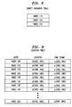
- each node applies computational geometry to the collected GPS information to select those surrounding nodes that facilitate geometric routing and sets up point-to-point links with the selected nodes (becoming direct neighbors) and forms a direct neighbor table.
- a direct neighbor table is shown in FIG. 8 for node 105 of FIG. 1.
- Nodes u ⁇ V and v ⁇ V form a link if and only if there exists a circle with u and v on the circumference that does not contain any other node w ⁇ V.
- Nodes u ⁇ V and v ⁇ V form an edge if and only if there exists a circle with u and v on the diameter that does not contain any other node w ⁇ V.
- Nodes u ⁇ V and v ⁇ V form an edge if and only if the intersection of the circles with radius D uv , one centered at u and one centered a v does not contain any other nodes w ⁇ V.
- Construction One results in a network that is I-routable .
- the network constructed by construction one results in a network where the local neighborhood of any node is the set of nodes that are directly connected to it. If GRA is used to route on this network where the local neighborhood is the 1-neighborhood , then any node can send packets to any other node.
- each node through limited flooding propagates its link information (i.e., its direct neighbor table) to enable all nodes to construct their k-neighborhood in step 615.
- link information i.e., its direct neighbor table
- node 105 receives the direct neighbor lists from nodes 110, 130 and 150 to construct the local topology table of FIG. 2. (It can be observed from FIGs.
- node 105 would also receive the direct neighbor tables of nodes 115, 120, 125, 135, 140 and 150.
- node 105 transmits its direct neighbor table along with a "time-to-live" field. The value of the time-to-live field is used to flood, or propagate, the direct neighbor table information of node 105 to a limited neighborhood.
- Each node that receives the "time-to-live” field and the direct neighbor table of node 105 decrements the value of the "time-to-live” field. As long as the value of the "time-to-live” field is greater than zero, that receiving node further transmits the direct neighbor table of node 105 to its direct neighbors (with the decremented value of the "time-to-live” field). However, when the value of the "time-to-live” field reaches zero, that receiving node does not further propagate the direct neighbor table of 105.
- each node knows the location (exact, or approximate) of all other nodes within a transmission radius, r .
- a node may be the case that a node is outside of the transmission range of a distant node and, therefore, cannot receive location information from that distant node.
- an alternative location update mechanism can also be used.
- a lazy update mechanism may be used in which position information is periodically updated.
- each node maintains a list of the locations of all known nodes along with a time stamp as to when that information was generated by those nodes.
- the time-stamp provides a vehicle for determining the age of the position information.
- s(i , k) is an integer value determined as a function of the month, day, year and time-of-day (using a 24 hour clock, e.g., 3:00 PM is 1500 hours).)
- the location table of FIG. 3 is modified to include the time-stamp field as shown in FIG. 9, where the reference node, i , is node 150 of FIG. 1.
- the table of FIG. 9 includes entries for node i itself (here, represented by node 150). This list of position and timestamps at a node i , is referred to as the location list, or location table, L(i) , at node i .
- each node periodically transmits its position to its direct neighbors (or, alternatively, to all nodes in its local topology) once every t 1 seconds. Further, once every t 2 seconds, each node transmits its location list L(i) to its direct neighbors (nodes within one hop).
- a flow chart of a lazy update method is shown in FIG. 10 for use in a receiving node, j . Let the receiving node j be a direct neighbor of node i . In step 905, the receiving node, j , receives location information p(i , k) from all nodes that are its direct neighbors.
- step 910 receiving node j , updates its location list L(j) to reflect the current position and time-stamp for its direct neighbor nodes. (At this point it is presumed that the time-stamp information is more recent than previous local topology location transmissions stored in L(j) .)
- step 915 node j receives the location lists, L(i)s, from direct neighbor nodes.
- step 920 node j adds and/or modifies entries in its location list L(j) by performing the following computation for each node k ⁇ V listed on each of the received location lists (effectively "merging" the various location lists):
- node j receives from a node a time-stamp associated with a node, k , not on its location list, then, by definition, s(i , k) > s(j , k ), and node j adds this new node, k , to its location list.
- node j updates location information for a node, i , already listed on its location list if the received time stamp from a particular location list is more current than the existing time-stamp, i.e., s(i , k) > s(j , k).
- node j has more current information for a particular node k , i.e., s(i , k) ⁇ s(j , k) , then no change to the location list is performed.
- location information is gradually propagated throughout the ad-hoc network by the transmission of location lists from one node to its direct neighbors. This lazy update procedure results in significantly less routing overhead than flooding the entire network with the position information, whenever the position information changes significantly.
- a loop it is possible for a loop to occur using a lazy update mechanism. For example, let t be the destination node for a given packet, and let node v receive this packet from a node u . If node v determines that the next hop for the packet is u , this results in a loop. In order to avoid this, when this situation happens, nodes u and v exchange p(u , t) , p(v , t) , s(u , t) and s(v , t) . The location of node t is resolved in favor of the node that has the more recent information. Both the nodes use this piece of information. With this modification, it can be shown that there can be no infinite loops in the route.
- Node 905 is a stored-program-control based processor architecture and includes processor 950; memory 960 (for storing program instructions and data, e.g., for communicating in accordance with the above-mentioned geometry-based routing protocol and storing location tables, etc.); communications interface(s) 965 for communicating with other nodes of the ad-hoc network via communication facilities as represented by path 966; and GPS element 970 for receiving GPS location information.
- Node 905 is also referred to as a router.
- the inventive concept present a simple routing protocol to route packets in ad-hoc networks - large or small.
- the foregoing merely illustrates the principles of the invention and it will thus be appreciated that those skilled in the art will be able to devise numerous alternative arrangements which, although not explicitly described herein, embody the principles of the invention and are within its scope.
- the GRP identifies the closest node to a distant node
- the GRP could be modified to identify any node that is closer to the distant node than the reference node.
- the GRP could be used in other forms of packet networks such as wired networks, or networks that have combinations of wired and wireless links.
Abstract
In an ad-hoc mobile network, a geometry-based routing protocol (GRP)
is used to route traffic from a source node to a destination node. In order for GRP to be
effective, the network needs to have certain routability characteristics. To that end, each
node collects location information from surrounding nodes and uses the collected
location information to select those surrounding nodes that facilitate geometric routing
and sets up point-to-point links with the selected nodes (becoming direct neighbors).
The node then constructs its k-neighborhood, (where the value of k represents the
maximum number of hops needed to reach any node in the desired local topology) by
exchanging its list of direct neighbor nodes with other nodes.
Description
- This invention relates generally to communications and, more particularly, to wireless systems.
- An "ad-hoc" mobile network (ad-hoc network) is a wireless network that comprises a collection of nodes whose positions are continually changing. Unlike a regular wireless network, one can view an ad-hoc network as a network with no fixed infrastructure. For example, all the nodes function as routers and perhaps as base stations; and the mobility of the nodes causes frequent changes in network topology.
- It is the varying network topology of an ad-hoc network that causes difficulty in applying routing techniques used in a conventional wireless network. In the latter, the nodes in the network are stationary and the links connecting the nodes go down infrequently. As such, it is possible to maintain the whole network topology at each node by sending topology-related information to all the nodes in the network via, what is known in the art as, "link-state," updates. Since nodes go down infrequently - link-state updates are infrequent - and this approach works quite well in a conventional wireless network. However, in an ad-hoc network link-state changes are more frequent because of the shifting topology, thus generating many more link-state update messages throughout the ad-hoc network - and consuming valuable bandwidth in the process. Also, construction of consistent routing tables is difficult because of the delay involved in propagating link-state information.
- Considering these factors, routing protocols for ad-hoc networks can be classified broadly into two categories: "table-driven" and "source initiated on-demand." Table-driven routing protocols are similar to the above-mentioned conventional wireless routing approach, i.e., each node attempts to maintain consistent, up-to-date, routing information for all other nodes in the network. Examples of table driven routing protocols are "Destination-Sequenced-Distance-Vector" (DSDV), "Clusterhead Gateway Switch Routing" (CGSR), and the "Wireless Routing Protocol" (WRP) protocols. In contrast, source initiated on-demand routing protocols create routing information only when a source node needs a route to a given destination. Examples of source initiated on-demand routing protocols include "Ad-Hoc On-Demand Distance Vector" (AODV), "Dynamic Source Routing" (DSR), "Temporally Ordered Routing Algorithm" (TORA), and the "Zone Routing Protocol" (ZRP) protocol.
- As an illustration of a source initiated on-demand protocol consider ZRP. In ZRP, each node maintains the whole network topology for a local area, or zone, around it. As such, if the node (i.e., the source node) has to send a packet to a destination address in the zone, that routing information is already available. However, if the source node has to send a packet to a destination address outside their zone, then the node initiates a query to all the nodes in the edge of its zone (i.e., edge nodes). If one of these edge nodes has the routing information for the destination address, then that routing information is passed on back to the source node.
- We have observed that the above-mentioned forms of ad-hoc network routing protocols generally require a node maintaining accurate information, in one form or another, about how to route to a node in regions that are far away from it. As such, if the number of nodes is large and if there is reasonable mobility of the nodes, getting this information becomes difficult ― if not impractical. Therefore, we have devised a geometry-based routing protocol (GRP) in which a source nodes routes a packet to a destination node outside of its local node topology (referred to herein as the local topology) as a function of the distance to the location of a destination node. In accordance with the invention, each node selects a subset of nodes it can "hear" to establish point-to-point links. These links are established in such a manner as to facilitate geometric routing.
- In an embodiment of the invention, a source node collects location information from surrounding nodes and uses the collected location information to select those surrounding nodes that facilitate geometric routing and sets up point-to-point links with the selected nodes (becoming direct neighbors). The source node then constructs its k-neighborhood, (where the value of k represents the maximum number of hops needed to reach any node in the desired local topology) by exchanging its list of direct neighbor nodes with other nodes.
-
- FIG. 1 shows a portion of an ad-hoc network embodying the principles of the invention;
- FIG. 2 shows an illustrative local topology table;
- FIG. 3 shows an illustrative location table;
- FIG. 4 shows an illustrative flow chart for use in routing a packet in an ad-hoc network;
- FIG. 5 shows an illustrative routing table;
- FIG. 6 shows an illustrative 2-region for
node 105 of FIG. 1; - FIG. 7 shows an illustrative flow chart for use in constructing a local topology;
- FIG. 8 shows an illustrative direct neighbor table;
- FIG. 9 shows another illustrative location table;
- FIG. 10 shows an illustrative flow chart for use in a lazy update procedure; and
- FIG. 11 shows an illustrative high-level block diagram of a node for use in the ad-hoc network of FIG. 1.
-
- A portion of an illustrative ad-hoc network embodying the principles of the invention is shown in FIG. 1. Other than the inventive concept, the elements shown in FIG. 1 are well-known and will not be described in detail. For example,
node 105 includes stored-program-control processors, memory, and appropriate interface cards for wireless communications. (The exact form of wireless transmission used, e.g., the use of carrier-division multiple access (CDMA), is not relevant to the inventive concept and, as such, is not described herein.) For the purposes of this example, it is assumed that each node of the ad-hoc network refers to a mobile device that allows users (mobile user stations, terminals, etc. (not shown)) to access the ad-hoc network and also provides routing functions for packets/data traversing the network. Each node transmits an omnidirectional pilot signal and is capable of communicating with other nodes using a signaling protocol to transfer information, such as the earlier-mentioned link-state information, between nodes. (Pilots and signaling protocols are known in the art and, as such, are not described herein.) The omnidirectional antenna and pilot signal are part of a topology sensing scheme (referred to further below) which enables nodes to sense the presence of one another and also to exchange some information useful for making link setup decisions. In general, and other than the below-described inventive concept, the nodes use this information to decide which of their neighboring nodes they should have direct (point-to-point) links with and then proceed to establish these links. The point-to-point links are preferably supported by directional antennas. - For the sake of simplicity it is assumed that all nodes with a transmission radius, r, of
node 105 are capable of communicating withnode 105. - At this point, the following definitions are made:
- V- represents the set of all nodes in the ad-hoc network;
- v, w, u, i, j - represent various nodes of the ad-hoc network;
- r - transmission radius for a node, i.e., all nodes within the transmission radius are capable of communicating with that node;
- N(v) - represents the local topology of a node, v;
- Sk(v) - the k-neighborhood of a node v; i.e., a local topology of node v where all nodes are within k hops of node v;
- Hvw - the minimum number of hops between a node v and a node w, where w ∈ N(v);
- Nvw - the next hop node from a node v to a node w, where w ∈ N(v);
- l(v) - represents the location of a node v; and
- Dvw - represents the distance between two nodes, v and w; where
-
- It is assumed that each node further comprises global positioning system (GPS) equipment (not shown in FIG. 1), as known in the art, for determining its own location (in two dimensions) on the globe. In accordance with the invention, each node of the ad-hoc network implements a geometry-based routing protocol (GRP) (also referred to as a geometry-based routing algorithm (GRA) or position-based routing) such that:
- each node has its own defined local topology, (also referred to as a local network or a local neighborhood) (described further below) which may, or may not, be different than the local topologies of other nodes; and
- each node stores location information (approximate or exact) of the nodes of the ad-hoc network (those nodes in the local topology and those nodes outside of, or distant from, the local topology).
-
- In other words, in the GRP each node knows its local topology for a subset of nodes of the ad-hoc network (connectivity and location) and only location information for other, or distant, nodes of the ad-hoc network (i.e., connectivity is not known for these distant nodes). As will become apparent from the description below, the GRP is capable of implementation using conventional programming techniques, which, as such, will not be described herein.
- Illustratively, FIG. 1 shows a
local topology 100 fornode 105. As can be observed from FIG. 1,local topology 100 not only defines the nodes that are a part oflocal topology 100 but also hownode 105 is connected to these nodes (i.e., a "network graph," or simply "graph"). It is assumed that all communications are bi-directional and hence the graph is undirected; and thatlocal topology 100 is non-hierarchical. Illustratively,node 105 stores in memory (not shown) a local topology table (as illustrated in FIG. 2), which corresponds tolocal topology 100 and a location table (as illustrated in FIG. 3), which stores location information for nodes (including nodes outside the local topology). As defined above,local topology 100 is representative of a 2-neighborhood fornode 105, i.e., S2(105), since all nodes oflocal topology 100 can be reached fromnode 105 in 2, or fewer, hops. As used herein,node 105 is the reference node forlocal topology 100. - As noted, the local topology table of FIG. 2 lists all the nodes currently in the local topology for
node 105 and the connection between nodes. For example, ifnode 105 has a packet to transmit tonode 115,node 105 transmits the packet to the next hop node, which is identified asnode 110 from the local topology table. From this table, the total number of hops to get tonode 115 is k = 2. This is also illustrated in FIG. 1 byarrow 101. Creation of the local topology table is described further below. - Although
node 105 is capable of communicating with all nodes within the transmission radius r,node 105 only communicates with nodes with which it has established point-to-point links (i.e., its direct neighbors). Similarly, other nodes only communicate withnode 105 ifnode 105 is their direct neighbor. In other words, nodes are preferably connected as point-to-point wireless links that gives rise to a k-neighborhood for a node, which is referred to herein as the local topology for that node. (Also, as noted above, it is possible to use directional antennae and focused beams to communicate between the neighbors in the graph ― thereby increasing the capacity of the system.) - Since each node has its own local topology and location information for nodes (including those outside it local topology), the GRA is defined as follows. Let t be the destination address (of a destination, or end, node) of a packet that arrives at a node v, which has a local topology, N(v). In accordance with the GRA, if t ≠ v, node v determines:where node v forwards the packet to node Nvw unless w = v (i.e., the reference node itself is the closest node) in which case the packet is dropped.

- Using the GRA, the packet, in effect, migrates from local topology to local topology until reaching that local topology within which the end node resides.
- In the context of FIG. 1, the GRA is illustrated as follows, and as is shown in the flow chart of FIG. 4. Assume that node 105 (the source node, v, of equation (2)) receives a packet (not shown) for transmission to node 205 (the end node, t, of equation(2)) in
step 405 of FIG. 4.Node 105 searches its local topology table to see ifnode 205 is a part of its local topology instep 410. If it is,node 105 simply sends the packet to the next hop node identified in its local topology table instep 415. On the other hand ifnode 205 is not a part of the local topology fornode 105,node 105 performs the geometry-based routing protocol instep 420 to identify the closest node, in its local topology, tonode 205. In particular,node 105 performs equation (2) for all nodes that are a part of itslocal topology 100.Node 105 evaluates the distance fromnode 205 to each node in its local topology 100 (using equation (1) and the location information from the location table shown in FIG. 3). This is illustrated in FIG. 1 by three dotted line arrows D140 , 205 ; D105 , 205 ; and D150 , 205 , which correspond to the distance calculations of equation (1) betweennodes local topology 100 are not shown). Once the closest node is identified,node 105 sends the packet to that node oflocal topology 100 that has the minimum distance tonode 205, e.g., here assumed to benode 140.Node 105 routes the packet tonode 140 via the local topology table, instep 415 of FIG. 4 (i.e., the packet is sent to thenext hop node 130 as indicated in the local topology table of FIG. 2). As should be readily apparent, the next hop node then performs the GRA using its local topology table. (Although not shown in the flow chart of FIG. 4, suitable error conditions can also be added to process the packet in certain situations. For example, if there is no location information fornode 205 in the location table, the packet is dropped.) - In the application of the GRA within a local topology it is important to ensure that there are no "loops" in the routing. One possible cause of a loop in the GRA routing is the situation where two nodes are the same distance from the destination node. As such, an alternative to equation (2) is equation (3), below:where it is assumed that ε is a very small number. The implication of ε is that if there are two nodes whose distance to the end node is the same, then the tie is broken in favor of the node that is closer to u in terms of hop count.

- Also, rather than making routing calculations on-the-fly as packets arrive at a node as illustrated in FIG. 4, a routing table can be constructed a priori using the calculations described earlier and packet routing decisions can be made on the basis of-the entries in the routing table. Such an illustrative routing table is shown in FIG. 5. This routing table uses the information from both the local topology table illustrated in FIG. 2 and the location table illustrated in FIG. 3, along with the above-described routing calculations (e.g., equation (3)). Using the same example above, and as illustrated in FIG. 5, a packet received at
node 105 and destined fornode 205 is routed tonode 130 according to the routing table entry. - As described above, each node has its own local topology. A method for constructing such local topologies is described below.
- As noted above, Sk(v) is a k-neighborhood of a node, i.e., the set of nodes that are within k hops of that node. The following additional definition is made:
- Rk(v) ― the k-region of a node v, which is the set of points in the two dimensional plane that are closer to node v than to any other node in Sk(v).
- Note that Rk(v) is constructed as follows. Assume that all nodes are
positioned at their respective locations on the plane. Draw a straight line joining node v
to some
node u ∈ Sk(v). Construct the perpendicular bisector of this line. This perpendicular
bisector represents a half plane where node v lies in one half space. Let this half space be
represented by Pvu . Note that if node w ∈ Pvu , then w is closer to v than to u. This
process of constructing Pvu is repeated for every u ∈ Sk(v), and Rk(v) is the intersection of
the half-spaces. It can be shown that there is loopless delivery of packets using GRA if,
and only if, there is no node v ∈ V for which there exists a w ∈ V such that w ∈ Rk(v). An
illustrative example of a k-region for
node 105 of FIG. 1 is shown in FIG. 6, which in this example is a 2-region, R2(105). Given this condition, a flow chart of a method for use in a node for computing a local topology is shown in FIG. 7. -
- It is assumed that each node of the ad-hoc network performs the method of FIG. 7 every second to continually update, or create, its local topology anew. (Faster, or slower rates may be used depending on the mobility of the nodes of the ad-hoc network.) At a high level, each node first constructs point-to-point links to a subset of nodes within hearing distance using location information - thus, determining its direct neighbors (represented by
steps 605 and 610). Then, each node propagates its direct neighbor information through limited flooding to enable each node to construct its k-neighborhood, Sk(v), for a predefined value of k as represented bystep 615. (As noted above, it is presumed that each node uses the same value of k.) Thus, a local topology is formed for a reference node. - In particular, each node uses a topology sensing scheme in
step 605. In this topology sensing scheme, each node periodically (or continually) broadcasts an omnidirectional pilot signal modified to additionally convey location information to any node within its transmission radius, r. (As noted above, it is assumed that two dimensional GPS coordinates are provided by each transmitting node and it is these two dimensional GPS coordinates additionally transmitted in the pilot signal.) In the context ofstep 605, each node listens for pilot signals transmitted by other nodes within hearing distance and recovers the GPS information for each received pilot signal for storage in a table such as the location table of FIG. 3. Thus, instep 605 each node collects GPS information for potential neighboring nodes. (Although the particular form of the omnidirectional pilot signal is not necessary for the inventive concept, for those readers interested, an illustrative omnidirectional pilot signal is described in the above-referenced, co-pending, commonly assigned, U.S. Patent application of Ahmed et al., entitled "A Topology Sensing Scheme for Networks with Mobile Nodes.") Instep 610, each node applies computational geometry to the collected GPS information to select those surrounding nodes that facilitate geometric routing and sets up point-to-point links with the selected nodes (becoming direct neighbors) and forms a direct neighbor table. (An illustrative direct neighbor table is shown in FIG. 8 fornode 105 of FIG. 1.) Illustratively, there are at least three ways a node can construct its direct neighbor table using the collected GPS information. - Nodes u ∈ V and v ∈ V form a link if and only if there exists a circle with u and v on the circumference that does not contain any other node w ∈ V.
- Nodes u ∈ V and v ∈ V form an edge if and only if there exists a circle with u and v on the diameter that does not contain any other node w ∈ V.
- Nodes u ∈ V and v ∈ V form an edge if and only if the intersection of the circles with radius Duv , one centered at u and one centered a v does not contain any other nodes w ∈ V.
- It can be shown that if any of these three constructions is not connected, then no connected network can be formed. Construction One results in a network that is I-routable. In other words, the network constructed by construction one results in a network where the local neighborhood of any node is the set of nodes that are directly connected to it. If GRA is used to route on this network where the local neighborhood is the 1-neighborhood, then any node can send packets to any other node. Network constructions two and three result in sparser networks (the number of links is lower than construction one). From simulation experiments, it can be shown that these networks are also almost k-routable, e.g., for k = 2, or k = 4.
- After forming links with those nodes within hearing distance that meet one of the above-described criteria, each node through limited flooding propagates its link information (i.e., its direct neighbor table) to enable all nodes to construct their k-neighborhood in
step 615. (Again, it is assumed that all nodes use the same value of k.) For example, and referring briefly back to FIG. 1, for a 2-neighborhood,node 105 receives the direct neighbor lists fromnodes node 125 was the direct neighbor tonode 130, a packet received atnode 105 and destined fornode 125 is routed bynode 105 tonode 130.) Similarly, if k was equal to three, then direct neighbor information is further propagated through limited flooding (e.g.,node 105 would also receive the direct neighbor tables ofnodes node 105 transmits its direct neighbor table along with a "time-to-live" field. The value of the time-to-live field is used to flood, or propagate, the direct neighbor table information ofnode 105 to a limited neighborhood. Each node that receives the "time-to-live" field and the direct neighbor table ofnode 105, decrements the value of the "time-to-live" field. As long as the value of the "time-to-live" field is greater than zero, that receiving node further transmits the direct neighbor table ofnode 105 to its direct neighbors (with the decremented value of the "time-to-live" field). However, when the value of the "time-to-live" field reaches zero, that receiving node does not further propagate the direct neighbor table of 105. Although not described herein, it can be mathematically shown that the above described methods for creating a local topology generate no loops in the routing. - As noted above, it was assumed that each node knows the location (exact, or approximate) of all other nodes within a transmission radius, r. However, as noted above, it may be the case that a node is outside of the transmission range of a distant node and, therefore, cannot receive location information from that distant node. Although one alternative is simply to drop packets if the location of the distant node is not found, an alternative location update mechanism can also be used. For example, a lazy update mechanism may be used in which position information is periodically updated.
- In this lazy update mechanism, each node maintains a list of the locations of all known nodes along with a time stamp as to when that information was generated by those nodes. Let p(i, k) be the position of node k as "seen" by node i and s(i, k) be a "time-stamp" at which the positional information was generated at node k. The time-stamp provides a vehicle for determining the age of the position information. (As can be observed from the discussion above, p(i, k) is a variation of l(v) and is two dimensional GPS information. Illustratively, s(i, k) is an integer value determined as a function of the month, day, year and time-of-day (using a 24 hour clock, e.g., 3:00 PM is 1500 hours).) The location table of FIG. 3 is modified to include the time-stamp field as shown in FIG. 9, where the reference node, i, is
node 150 of FIG. 1. For completeness, the table of FIG. 9 includes entries for node i itself (here, represented by node 150). This list of position and timestamps at a node i, is referred to as the location list, or location table, L(i), at node i. - In accordance with the lazy update method, each node periodically transmits its position to its direct neighbors (or, alternatively, to all nodes in its local topology) once every t1 seconds. Further, once every t2 seconds, each node transmits its location list L(i) to its direct neighbors (nodes within one hop). A flow chart of a lazy update method is shown in FIG. 10 for use in a receiving node, j. Let the receiving node j be a direct neighbor of node i. In
step 905, the receiving node, j, receives location information p(i, k) from all nodes that are its direct neighbors. Instep 910, receiving node j, updates its location list L(j) to reflect the current position and time-stamp for its direct neighbor nodes. (At this point it is presumed that the time-stamp information is more recent than previous local topology location transmissions stored in L(j).) Instep 915, node j receives the location lists, L(i)s, from direct neighbor nodes. Instep 920, node j adds and/or modifies entries in its location list L(j) by performing the following computation for each node k ∈ V listed on each of the received location lists (effectively "merging" the various location lists):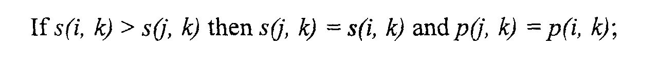

- Also, if node j receives from a node a time-stamp associated with a node, k, not on its location list, then, by definition, s(i, k) > s(j, k), and node j adds this new node, k, to its location list. Similarly, node j updates location information for a node, i, already listed on its location list if the received time stamp from a particular location list is more current than the existing time-stamp, i.e., s(i, k) > s(j, k). On the other hand, if node j has more current information for a particular node k, i.e., s(i, k) ≤ s(j, k), then no change to the location list is performed. Thus, location information is gradually propagated throughout the ad-hoc network by the transmission of location lists from one node to its direct neighbors. This lazy update procedure results in significantly less routing overhead than flooding the entire network with the position information, whenever the position information changes significantly.
- As can be observed from the above, there is a certain "warm-up" time for the ad-hoc network when using a lazy update mechanism during which some nodes will not have any information about distant nodes. As noted above, one option for the GRP routing method is to simply discard packets if the location to a distant node is not yet known.
- Also, it should be noted that it is possible for a loop to occur using a lazy update mechanism. For example, let t be the destination node for a given packet, and let node v receive this packet from a node u. If node v determines that the next hop for the packet is u, this results in a loop. In order to avoid this, when this situation happens, nodes u and v exchange p(u, t), p(v, t), s(u, t) and s(v, t). The location of node t is resolved in favor of the node that has the more recent information. Both the nodes use this piece of information. With this modification, it can be shown that there can be no infinite loops in the route.
- Turning briefly to FIG. 11, a high-level block diagram of a
representative node 905 for use in the ad-hoc network of FIG. 1 is shown.Node 905 is a stored-program-control based processor architecture and includesprocessor 950; memory 960 (for storing program instructions and data, e.g., for communicating in accordance with the above-mentioned geometry-based routing protocol and storing location tables, etc.); communications interface(s) 965 for communicating with other nodes of the ad-hoc network via communication facilities as represented bypath 966; andGPS element 970 for receiving GPS location information.Node 905 is also referred to as a router. - As described above, the inventive concept present a simple routing protocol to route packets in ad-hoc networks - large or small. The foregoing merely illustrates the principles of the invention and it will thus be appreciated that those skilled in the art will be able to devise numerous alternative arrangements which, although not explicitly described herein, embody the principles of the invention and are within its scope. For example, although the GRP identifies the closest node to a distant node, the GRP could be modified to identify any node that is closer to the distant node than the reference node. Also, although described in the context of a wireless application, the GRP could be used in other forms of packet networks such as wired networks, or networks that have combinations of wired and wireless links.
Claims (11)
- A method for use in a source node of a packet network for creating a local topology for the source node, the method comprising the steps of:determining those nodes of the packet network that are direct neighbors of the source node; andreceiving from at least the determined direct neighbors, each of their direct neighbor lists.
- The method of claim 1 further comprising the step of forming a local topology table from the received direct neighbor lists.
- The method of claim 1 wherein the local topology thus formed is a k-neighborhood of at least one.
- The method of claim 1 wherein the determining step includes the step of determining a node of the packet network is a direct neighbor of the source node if and only if there exists a circle, having a circumference, such that the node and the source node lie on the circumference of the circle and the circle does not contain any other node of the packet network.
- The method of claim 1 wherein the determining step includes the step of determining a node of the packet network is a direct neighbor of the source node if and only if there exists a circle, having a diameter, with the node and the source node on the diameter that does not contain any other node of the packet network.
- The method of claim 1 wherein the determining step includes the step of determining a node of the packet network is a direct neighbor of the source node if and only if an intersection of two circles does not include any other node of the packet network, where each circle has a radius equal to a distance between the node and the source node, and where one circle is centered at the source node and the other circle is centered at the node.
- A node of a packet network comprising:a communications interface for receiving location information from surrounding nodes of the packet network; anda processor for determining from the received location information those surrounding nodes that are direct neighbors of the node.
- The apparatus of claim 7 wherein the communications interface transmits the determined direct neighbor information to other nodes of the packet network for construction of a k-neighborhood, such that the value of k is at least one.
- The apparatus of claim 7 wherein the processor selects a surrounding node as a direct neighbor if and only if there exists a circle, having a circumference, such that the node and the surrounding node lie on the circumference of the circle and the circle does not contain any other node of the packet network.
- The apparatus of claim 7 wherein the processor selects a surrounding node as a direct neighbor if and only if there exists a circle, having a diameter, with the surrounding node and the node on the diameter that does not contain any other node of the packet network.
- The apparatus of claim 7 wherein the processor selects a surrounding node as a direct neighbor if and only if an intersection of two circles does not include any other node of the packet network, where each circle has a radius equal to a distance between the surrounding node and the node, and where one circle is centered at the node and the other circle is centered at the surrounding node.
Applications Claiming Priority (2)
| Application Number | Priority Date | Filing Date | Title |
|---|---|---|---|
| US52559700A | 2000-03-14 | 2000-03-14 | |
| US525597 | 2000-03-14 |
Publications (1)
| Publication Number | Publication Date |
|---|---|
| EP1134939A1 true EP1134939A1 (en) | 2001-09-19 |
Family
ID=24093896
Family Applications (1)
| Application Number | Title | Priority Date | Filing Date |
|---|---|---|---|
| EP00309051A Withdrawn EP1134939A1 (en) | 2000-03-14 | 2000-10-16 | Location based routing for mobile ad-hoc networks |
Country Status (3)
| Country | Link |
|---|---|
| EP (1) | EP1134939A1 (en) |
| JP (1) | JP2001268128A (en) |
| CA (1) | CA2329549A1 (en) |
Cited By (23)
| Publication number | Priority date | Publication date | Assignee | Title |
|---|---|---|---|---|
| WO2004112333A1 (en) * | 2003-06-10 | 2004-12-23 | Cisco Technology, Inc. | Method and apparatus for packet classification and rewriting |
| WO2006039189A1 (en) * | 2004-09-29 | 2006-04-13 | Kyocera Wireless Corp. | Method and apparatus for implementation of ad hoc mesh network |
| WO2007012076A2 (en) | 2005-07-20 | 2007-01-25 | Raytheon Company | Dynamic system and method of establishing communication with objects in wireless cellular network |
| US7397771B2 (en) | 2003-03-25 | 2008-07-08 | Fujitsu Limited | Communication terminal and communication method |
| EP2237614A1 (en) | 2009-03-30 | 2010-10-06 | The Boeing Company | Mobile ad hoc network |
| KR101038025B1 (en) * | 2003-03-28 | 2011-05-31 | 레노보 (싱가포르) 피티이. 엘티디. | Routing in wireless ad-hoc networks |
| WO2011086235A1 (en) * | 2010-01-14 | 2011-07-21 | Teknologian Tutkimuskeskus Vtt | A method and a device for optimizing data transfer in a wireless communication network |
| US8019351B2 (en) | 2004-02-09 | 2011-09-13 | Qualcomm, Incorporated | Multi-hop communications in a wireless network |
| WO2011100587A3 (en) * | 2010-02-12 | 2011-12-15 | Tekelec | Methods, systems, and computer readable media for inter-diameter-message processor routing |
| CN103080969A (en) * | 2010-09-13 | 2013-05-01 | 日本电气株式会社 | Coordinated information collection system, coordinated information collection method and program |
| EP2611233A1 (en) * | 2011-12-29 | 2013-07-03 | Thales | Method of communication between two distinct networks comprising radio communication nodes, processing module and associated computer programe |
| US8547908B2 (en) | 2011-03-03 | 2013-10-01 | Tekelec, Inc. | Methods, systems, and computer readable media for enriching a diameter signaling message |
| US8578050B2 (en) | 2010-02-12 | 2013-11-05 | Tekelec, Inc. | Methods, systems, and computer readable media for providing peer routing at a diameter node |
| US8750126B2 (en) | 2009-10-16 | 2014-06-10 | Tekelec, Inc. | Methods, systems, and computer readable media for multi-interface monitoring and correlation of diameter signaling information |
| US8855016B2 (en) | 2009-03-30 | 2014-10-07 | The Boeing Company | Method for maintaining links in a mobile ad hoc network |
| US8958306B2 (en) | 2009-10-16 | 2015-02-17 | Tekelec, Inc. | Methods, systems, and computer readable media for providing diameter signaling router with integrated monitoring functionality |
| CN104472008A (en) * | 2012-07-17 | 2015-03-25 | 宝洁公司 | Systems and methods for networking consumer devices |
| US9647936B2 (en) | 2010-02-12 | 2017-05-09 | Tekelec, Inc. | Methods, systems, and computer readable media for routing diameter messages at a diameter signaling router |
| US9729454B2 (en) | 2015-01-21 | 2017-08-08 | Oracle International Corporation | Methods, systems, and computer readable media for balancing diameter message traffic received over long-lived diameter connections |
| US10027577B2 (en) | 2015-07-29 | 2018-07-17 | Oracle International Corporation | Methods, systems, and computer readable media for peer aware load distribution |
| US10959157B2 (en) | 2017-08-17 | 2021-03-23 | Hype Labs Inc. | Systems and methods for wireless communication network loop detection |
| US10999202B2 (en) | 2018-11-30 | 2021-05-04 | Oracle International Corporation | Methods, systems, and computer readable media for distributing Sigtran connections among signal transfer point (STP) message processors |
| US11576072B2 (en) | 2020-09-21 | 2023-02-07 | Oracle International Corporation | Methods, systems, and computer-readable media for distributing S1 connections to mobility management entities (MMEs) and N2 connections to access and mobility management functions (AMFs) |
Families Citing this family (6)
| Publication number | Priority date | Publication date | Assignee | Title |
|---|---|---|---|---|
| JP3805701B2 (en) * | 2002-03-01 | 2006-08-09 | 株式会社国際電気通信基礎技術研究所 | Routing method and router apparatus for wireless network |
| JP3844768B2 (en) * | 2002-11-20 | 2006-11-15 | 富士通株式会社 | Wireless terminal device |
| JP4544072B2 (en) * | 2005-07-20 | 2010-09-15 | ブラザー工業株式会社 | Node device, computer program, information distribution system, and network participation method |
| WO2009117290A2 (en) * | 2008-03-18 | 2009-09-24 | On-Ramp Wireless, Inc. | Random phase multiple access system with meshing |
| US9832080B2 (en) * | 2012-05-03 | 2017-11-28 | Philips Lighting Holding B.V. | Method and device for commissioning of nodes of a network |
| CN113542135B (en) * | 2021-08-04 | 2023-04-07 | 湖南快乐阳光互动娱乐传媒有限公司 | CDN communication method, system, client and server |
Citations (1)
| Publication number | Priority date | Publication date | Assignee | Title |
|---|---|---|---|---|
| US5959568A (en) * | 1996-06-26 | 1999-09-28 | Par Goverment Systems Corporation | Measuring distance |
-
2000
- 2000-10-16 EP EP00309051A patent/EP1134939A1/en not_active Withdrawn
- 2000-11-14 JP JP2000346178A patent/JP2001268128A/en active Pending
- 2000-12-22 CA CA002329549A patent/CA2329549A1/en not_active Abandoned
Patent Citations (1)
| Publication number | Priority date | Publication date | Assignee | Title |
|---|---|---|---|---|
| US5959568A (en) * | 1996-06-26 | 1999-09-28 | Par Goverment Systems Corporation | Measuring distance |
Non-Patent Citations (3)
| Title |
|---|
| AMOURIS K N ET AL: "A POSITION-BASED MULTI-ZONE ROUTING PROTOCOL FOR WIDE AREA MOBILE AD-HOC NETWORKS", HOUSTON, TX, MAY 16 - 20, 1999,NEW YORK, NY: IEEE,US, vol. CONF. 49, 16 May 1999 (1999-05-16), pages 1365 - 1369, XP000903268, ISBN: 0-7803-5566-0 * |
| JERZY W. JAROMCZYK AND GODFRIED T. TOUSSAINT: "Relative Neighborhood Graphs and Their Relatives", PROCEEDINGS OF THE IEEE, vol. 80, no. 9, 9 September 1992 (1992-09-09), pages 1502 - 1517, XP002164674 * |
| Z J HAAS ET AL: "The Zone Routing Protocol (ZRP) for Ad Hoc Networks", INTERNET DRAFT, November 1997 (1997-11-01), XP002153515 * |
Cited By (49)
| Publication number | Priority date | Publication date | Assignee | Title |
|---|---|---|---|---|
| US7397771B2 (en) | 2003-03-25 | 2008-07-08 | Fujitsu Limited | Communication terminal and communication method |
| KR101038025B1 (en) * | 2003-03-28 | 2011-05-31 | 레노보 (싱가포르) 피티이. 엘티디. | Routing in wireless ad-hoc networks |
| WO2004112333A1 (en) * | 2003-06-10 | 2004-12-23 | Cisco Technology, Inc. | Method and apparatus for packet classification and rewriting |
| US7953088B2 (en) | 2003-06-10 | 2011-05-31 | Cisco Technology, Inc. | Method and apparatus for packet classification and rewriting |
| CN1781286B (en) * | 2003-06-10 | 2010-09-29 | 思科技术公司 | Method and apparatus for packet classification and rewriting |
| US8019351B2 (en) | 2004-02-09 | 2011-09-13 | Qualcomm, Incorporated | Multi-hop communications in a wireless network |
| WO2006039189A1 (en) * | 2004-09-29 | 2006-04-13 | Kyocera Wireless Corp. | Method and apparatus for implementation of ad hoc mesh network |
| US8155027B2 (en) | 2005-07-20 | 2012-04-10 | Raytheon Company | Dynamic system and method of establishing communication with objects |
| WO2007012076A2 (en) | 2005-07-20 | 2007-01-25 | Raytheon Company | Dynamic system and method of establishing communication with objects in wireless cellular network |
| AU2006269862B2 (en) * | 2005-07-20 | 2011-09-15 | Raytheon Company | Dynamic system and method of establishing communication with objects in wireless cellular network |
| WO2007012076A3 (en) * | 2005-07-20 | 2007-05-18 | Raytheon Co | Dynamic system and method of establishing communication with objects in wireless cellular network |
| EP2237614A1 (en) | 2009-03-30 | 2010-10-06 | The Boeing Company | Mobile ad hoc network |
| US8385211B2 (en) | 2009-03-30 | 2013-02-26 | The Boeing Company | Method for routing in a mobile ad hoc network |
| US8855016B2 (en) | 2009-03-30 | 2014-10-07 | The Boeing Company | Method for maintaining links in a mobile ad hoc network |
| US8958306B2 (en) | 2009-10-16 | 2015-02-17 | Tekelec, Inc. | Methods, systems, and computer readable media for providing diameter signaling router with integrated monitoring functionality |
| US8750126B2 (en) | 2009-10-16 | 2014-06-10 | Tekelec, Inc. | Methods, systems, and computer readable media for multi-interface monitoring and correlation of diameter signaling information |
| US8995438B2 (en) | 2010-01-14 | 2015-03-31 | Teknologian Tutkimuskeskus Vtt | Method and a device for optimizing data transfer in a wireless communication network |
| WO2011086235A1 (en) * | 2010-01-14 | 2011-07-21 | Teknologian Tutkimuskeskus Vtt | A method and a device for optimizing data transfer in a wireless communication network |
| US8532110B2 (en) | 2010-02-12 | 2013-09-10 | Tekelec, Inc. | Methods, systems, and computer readable media for diameter protocol harmonization |
| CN102812671B (en) * | 2010-02-12 | 2015-06-17 | 泰克莱克股份有限公司 | Methods, systems, and computer readable media for inter-diameter-message processor routing |
| US8483233B2 (en) | 2010-02-12 | 2013-07-09 | Tekelec, Inc. | Methods, systems, and computer readable media for providing local application routing at a diameter node |
| US8498202B2 (en) | 2010-02-12 | 2013-07-30 | Tekelec, Inc. | Methods, systems, and computer readable media for diameter network management |
| US8504630B2 (en) | 2010-02-12 | 2013-08-06 | Tekelec, Inc. | Methods, systems, and computer readable media for diameter application loop prevention |
| US8527598B2 (en) | 2010-02-12 | 2013-09-03 | Tekelec, Inc. | Methods, systems, and computer readable media for answer-based routing of diameter request messages |
| US9647936B2 (en) | 2010-02-12 | 2017-05-09 | Tekelec, Inc. | Methods, systems, and computer readable media for routing diameter messages at a diameter signaling router |
| US9088478B2 (en) | 2010-02-12 | 2015-07-21 | Tekelec, Inc. | Methods, systems, and computer readable media for inter-message processor status sharing |
| US8554928B2 (en) | 2010-02-12 | 2013-10-08 | Tekelec, Inc. | Methods, systems, and computer readable media for providing origin routing at a diameter node |
| US8578050B2 (en) | 2010-02-12 | 2013-11-05 | Tekelec, Inc. | Methods, systems, and computer readable media for providing peer routing at a diameter node |
| US8601073B2 (en) | 2010-02-12 | 2013-12-03 | Tekelec, Inc. | Methods, systems, and computer readable media for source peer capacity-based diameter load sharing |
| US8644324B2 (en) | 2010-02-12 | 2014-02-04 | Tekelec, Inc. | Methods, systems, and computer readable media for providing priority routing at a diameter node |
| US8478828B2 (en) | 2010-02-12 | 2013-07-02 | Tekelec, Inc. | Methods, systems, and computer readable media for inter-diameter-message processor routing |
| US8792329B2 (en) | 2010-02-12 | 2014-07-29 | Tekelec, Inc. | Methods, systems, and computer readable media for performing diameter answer message-based network management at a diameter signaling router (DSR) |
| US8799391B2 (en) | 2010-02-12 | 2014-08-05 | Tekelec, Inc. | Methods, systems, and computer readable media for inter-diameter-message processor routing |
| WO2011100587A3 (en) * | 2010-02-12 | 2011-12-15 | Tekelec | Methods, systems, and computer readable media for inter-diameter-message processor routing |
| CN102812671A (en) * | 2010-02-12 | 2012-12-05 | 泰克莱克股份有限公司 | Methods, systems, and computer readable media for inter-diameter-message processor routing |
| US8996636B2 (en) | 2010-02-12 | 2015-03-31 | Tekelec, Inc. | Methods, systems, and computer readable media for answer-based routing of diameter request messages |
| US8995256B2 (en) | 2010-02-12 | 2015-03-31 | Tekelec, Inc. | Methods, systems, and computer readable media for performing diameter answer message-based network management at a diameter signaling router (DSR) |
| CN103080969A (en) * | 2010-09-13 | 2013-05-01 | 日本电气株式会社 | Coordinated information collection system, coordinated information collection method and program |
| CN103080969B (en) * | 2010-09-13 | 2016-03-16 | 日本电气株式会社 | Cooperative information collection system and cooperative information collection method |
| US8547908B2 (en) | 2011-03-03 | 2013-10-01 | Tekelec, Inc. | Methods, systems, and computer readable media for enriching a diameter signaling message |
| US9042254B2 (en) | 2011-12-29 | 2015-05-26 | Thales | Communication method between two distinct networks with radio communication nodes, associated processing module and computer program |
| FR2985403A1 (en) * | 2011-12-29 | 2013-07-05 | Thales Sa | METHOD OF COMMUNICATING BETWEEN TWO DISTINCT NETWORKS OF RADIOCOMMUNICATION NODES, PROCESSING MODULE AND CORRESPONDING COMPUTER PROGRAM |
| EP2611233A1 (en) * | 2011-12-29 | 2013-07-03 | Thales | Method of communication between two distinct networks comprising radio communication nodes, processing module and associated computer programe |
| CN104472008A (en) * | 2012-07-17 | 2015-03-25 | 宝洁公司 | Systems and methods for networking consumer devices |
| US9729454B2 (en) | 2015-01-21 | 2017-08-08 | Oracle International Corporation | Methods, systems, and computer readable media for balancing diameter message traffic received over long-lived diameter connections |
| US10027577B2 (en) | 2015-07-29 | 2018-07-17 | Oracle International Corporation | Methods, systems, and computer readable media for peer aware load distribution |
| US10959157B2 (en) | 2017-08-17 | 2021-03-23 | Hype Labs Inc. | Systems and methods for wireless communication network loop detection |
| US10999202B2 (en) | 2018-11-30 | 2021-05-04 | Oracle International Corporation | Methods, systems, and computer readable media for distributing Sigtran connections among signal transfer point (STP) message processors |
| US11576072B2 (en) | 2020-09-21 | 2023-02-07 | Oracle International Corporation | Methods, systems, and computer-readable media for distributing S1 connections to mobility management entities (MMEs) and N2 connections to access and mobility management functions (AMFs) |
Also Published As
| Publication number | Publication date |
|---|---|
| JP2001268128A (en) | 2001-09-28 |
| CA2329549A1 (en) | 2001-09-14 |
Similar Documents
| Publication | Publication Date | Title |
|---|---|---|
| US6816460B1 (en) | Location based routing for mobile ad-hoc networks | |
| US7006453B1 (en) | Location based routing for mobile ad-hoc networks | |
| EP1134939A1 (en) | Location based routing for mobile ad-hoc networks | |
| EP1550318B1 (en) | Intelligent communication node using beacon in a mobile ad hoc network | |
| Ye et al. | A framework for reliable routing in mobile ad hoc networks | |
| KR100689305B1 (en) | Mobile Ad Hoc Network and Method for Detecting Variable Beacon Signals in Mobile Ad Hoc Network | |
| Wang et al. | A stable weight-based on-demand routing protocol for mobile ad hoc networks | |
| KR100932556B1 (en) | Routing path setting method for vehicle-to-vehicle communication and terminal device performing the same | |
| Arianmehr et al. | HybTGR: a hybrid routing protocol based on topological and geographical information in vehicular ad hoc networks | |
| KR100458207B1 (en) | Method of route discovery based on-demand in ad-hoc network | |
| JP2002171283A (en) | Method and device used for node of packet network | |
| Wang et al. | NCMDSDV: A neighbor coverage multipsth DSDV routing protocol for MANETs | |
| Kumar et al. | Geographical topologies of routing protocols in Vehicular Ad Hoc Networks-A survey | |
| KR101035417B1 (en) | Routing Method and Device Based on Reliable Link Zone in Ad-hoc Network | |
| Aneja et al. | WMN routing: state of the art survey | |
| Chigra et al. | Performance study of routing protocols based on node mobility in MANETs | |
| Giri et al. | Survey of Routing Protocols in MANET | |
| Jianwu et al. | A ranging-aided QoS routing protocol of UWB ad hoc network | |
| Lee et al. | Dynamic Source Routing (DSR) Protocol with Euclidean Effect in Mobile Ad Hoc Networks | |
| Motton et al. | A Review Report on Existing Routing Protocols in Vehicular Ad Hoc Networks (VANETS) | |
| Frey et al. | Episode 6: Routing | |
| Gao | A connected dominating-set-based routing in ad hoc wireless networks | |
| Bai | Routing in Mobile Ad-hoc Networks: Scalability and Efficiency | |
| Varia | Survey of Efficient Routing in VANET using Ant Colony Optimization | |
| Amouris et al. | Integrating position reporting, routing and mobility management in multihop packet radio networks |
Legal Events
| Date | Code | Title | Description |
|---|---|---|---|
| PUAI | Public reference made under article 153(3) epc to a published international application that has entered the european phase |
Free format text: ORIGINAL CODE: 0009012 |
|
| 17P | Request for examination filed |
Effective date: 20001026 |
|
| AK | Designated contracting states |
Kind code of ref document: A1 Designated state(s): AT BE CH CY DE DK ES FI FR GB GR IE IT LI LU MC NL PT SE |
|
| AX | Request for extension of the european patent |
Free format text: AL;LT;LV;MK;RO;SI |
|
| STAA | Information on the status of an ep patent application or granted ep patent |
Free format text: STATUS: THE APPLICATION IS DEEMED TO BE WITHDRAWN |
|
| 18D | Application deemed to be withdrawn |
Effective date: 20011011 |