EP1126681A2 - A network portal system and methods - Google Patents
A network portal system and methods Download PDFInfo
- Publication number
- EP1126681A2 EP1126681A2 EP01100131A EP01100131A EP1126681A2 EP 1126681 A2 EP1126681 A2 EP 1126681A2 EP 01100131 A EP01100131 A EP 01100131A EP 01100131 A EP01100131 A EP 01100131A EP 1126681 A2 EP1126681 A2 EP 1126681A2
- Authority
- EP
- European Patent Office
- Prior art keywords
- content
- provider
- interface
- universal
- client
- Prior art date
- Legal status (The legal status is an assumption and is not a legal conclusion. Google has not performed a legal analysis and makes no representation as to the accuracy of the status listed.)
- Withdrawn
Links
Images


Classifications
-
- G—PHYSICS
- G06—COMPUTING; CALCULATING OR COUNTING
- G06F—ELECTRIC DIGITAL DATA PROCESSING
- G06F8/00—Arrangements for software engineering
- G06F8/70—Software maintenance or management
- G06F8/76—Adapting program code to run in a different environment; Porting
-
- G—PHYSICS
- G06—COMPUTING; CALCULATING OR COUNTING
- G06F—ELECTRIC DIGITAL DATA PROCESSING
- G06F16/00—Information retrieval; Database structures therefor; File system structures therefor
- G06F16/90—Details of database functions independent of the retrieved data types
- G06F16/95—Retrieval from the web
- G06F16/954—Navigation, e.g. using categorised browsing
-
- G—PHYSICS
- G06—COMPUTING; CALCULATING OR COUNTING
- G06F—ELECTRIC DIGITAL DATA PROCESSING
- G06F40/00—Handling natural language data
- G06F40/10—Text processing
- G06F40/12—Use of codes for handling textual entities
- G06F40/151—Transformation
-
- G—PHYSICS
- G06—COMPUTING; CALCULATING OR COUNTING
- G06F—ELECTRIC DIGITAL DATA PROCESSING
- G06F9/00—Arrangements for program control, e.g. control units
- G06F9/06—Arrangements for program control, e.g. control units using stored programs, i.e. using an internal store of processing equipment to receive or retain programs
- G06F9/46—Multiprogramming arrangements
- G06F9/54—Interprogram communication
- G06F9/541—Interprogram communication via adapters, e.g. between incompatible applications
-
- G—PHYSICS
- G06—COMPUTING; CALCULATING OR COUNTING
- G06F—ELECTRIC DIGITAL DATA PROCESSING
- G06F9/00—Arrangements for program control, e.g. control units
- G06F9/06—Arrangements for program control, e.g. control units using stored programs, i.e. using an internal store of processing equipment to receive or retain programs
- G06F9/46—Multiprogramming arrangements
- G06F9/54—Interprogram communication
- G06F9/547—Remote procedure calls [RPC]; Web services
-
- G—PHYSICS
- G06—COMPUTING; CALCULATING OR COUNTING
- G06Q—INFORMATION AND COMMUNICATION TECHNOLOGY [ICT] SPECIALLY ADAPTED FOR ADMINISTRATIVE, COMMERCIAL, FINANCIAL, MANAGERIAL OR SUPERVISORY PURPOSES; SYSTEMS OR METHODS SPECIALLY ADAPTED FOR ADMINISTRATIVE, COMMERCIAL, FINANCIAL, MANAGERIAL OR SUPERVISORY PURPOSES, NOT OTHERWISE PROVIDED FOR
- G06Q10/00—Administration; Management
- G06Q10/10—Office automation; Time management
-
- H—ELECTRICITY
- H04—ELECTRIC COMMUNICATION TECHNIQUE
- H04L—TRANSMISSION OF DIGITAL INFORMATION, e.g. TELEGRAPHIC COMMUNICATION
- H04L67/00—Network arrangements or protocols for supporting network services or applications
- H04L67/01—Protocols
- H04L67/04—Protocols specially adapted for terminals or networks with limited capabilities; specially adapted for terminal portability
-
- H—ELECTRICITY
- H04—ELECTRIC COMMUNICATION TECHNIQUE
- H04L—TRANSMISSION OF DIGITAL INFORMATION, e.g. TELEGRAPHIC COMMUNICATION
- H04L67/00—Network arrangements or protocols for supporting network services or applications
- H04L67/34—Network arrangements or protocols for supporting network services or applications involving the movement of software or configuration parameters
-
- H—ELECTRICITY
- H04—ELECTRIC COMMUNICATION TECHNIQUE
- H04L—TRANSMISSION OF DIGITAL INFORMATION, e.g. TELEGRAPHIC COMMUNICATION
- H04L67/00—Network arrangements or protocols for supporting network services or applications
- H04L67/50—Network services
- H04L67/56—Provisioning of proxy services
- H04L67/567—Integrating service provisioning from a plurality of service providers
-
- H—ELECTRICITY
- H04—ELECTRIC COMMUNICATION TECHNIQUE
- H04L—TRANSMISSION OF DIGITAL INFORMATION, e.g. TELEGRAPHIC COMMUNICATION
- H04L67/00—Network arrangements or protocols for supporting network services or applications
- H04L67/50—Network services
- H04L67/56—Provisioning of proxy services
- H04L67/565—Conversion or adaptation of application format or content
-
- H—ELECTRICITY
- H04—ELECTRIC COMMUNICATION TECHNIQUE
- H04L—TRANSMISSION OF DIGITAL INFORMATION, e.g. TELEGRAPHIC COMMUNICATION
- H04L69/00—Network arrangements, protocols or services independent of the application payload and not provided for in the other groups of this subclass
- H04L69/30—Definitions, standards or architectural aspects of layered protocol stacks
- H04L69/32—Architecture of open systems interconnection [OSI] 7-layer type protocol stacks, e.g. the interfaces between the data link level and the physical level
- H04L69/322—Intralayer communication protocols among peer entities or protocol data unit [PDU] definitions
- H04L69/329—Intralayer communication protocols among peer entities or protocol data unit [PDU] definitions in the application layer [OSI layer 7]
Definitions
- This invention relates generally to network systems and in particular to network portal systems
- portals allow users to access a wide variety of applications, services, and data through a single entry point (the portal).
- Portal computing is a network solution that aims to make recent technological advances serve the way people actually work-or would like to work. Recognizing the advantages of portal computing, several service providers have already embraced the concept, albeit in a limited sense, offering their customers a growing number of application services. Notable examples include Yahoo!, Excite, and Lycos. Although these all started as search engines, they now offer such capabilities as e-mail, stock quotes, calendar facilities, etc.
- services or content provided by some provider systems may be incompatible with services or content provided by other provider systems and thus have a "stove-pipe" nature as to their presence and operation on networks.
- communication schemes for content or service which communication schemes again may be incompatible and not universally accessible or supported by all client systems. Accordingly, the existing portal products are limited to a subset of client systems and permit this subset of client systems to access at most a limited amount of content that is available.
- a network portal system allows the universal and integral use of different services by arbitrary client systems.
- the network portal system links, via a communication network, a plurality of content provider systems with a plurality of client systems.
- Each content provider system that offers content is associated with a content identifier, which in one embodiment is a URL scheme.
- the content is information that is transmittable over the communication network.
- the network portal system includes a web-top manager.
- the web-top manager receives a content request from a client system.
- each content request includes a content identifier of the content requested by the requesting client system.
- the content request includes a client system identifier and/or a content type.
- a process on the network portal system may determine the client system identifier and content types supported by the client device.
- the web-top manager in the network portal system communicates with a universal content broker system that also is in the network portal system.
- a universal content broker in the universal content broker system Upon receipt of a content request from the web-top manager, a universal content broker in the universal content broker system, using resources within the network portal system, selects a content provider system, which is able to provide the requested content.
- the universal content broker accesses the selected content provider system, and issues a request that results in the performance of the action specified in the request by the accessed provider system.
- the content in a raw data format is passed to the web-top manager.
- the web-top manager renders the requested content into a page that can be displayed by the requesting client system and this page is returned to the requesting client system.
- Provider systems are associated with the URL schemes they implement.
- a service or content is obtained by passing a uniform resource indicator URL to a provider system.
- the provider system infers what the scheme is and therefore what provider system can create the content.
- Provider systems create content objects that implement defined network portal interfaces associated with content such that a client system can infer and or operate on: MIME type, child content, commands, properties, changes to state.
- new content may be created from existing content and stored to be retrieved later.
- the new content may be related to the existing content.
- An example of which could be an address book that may only store content of type "folder” and "address".
- the network portal system includes a web-top manager and a universal content broker system.
- the web-top manager is configured to receive a content request from a user device, where the content request includes a content provider identifier.
- the universal content broker system is coupled to the web-top manager.
- the universal content broker system includes a plurality of content providers. Each content provider in the plurality of content providers is associated with a different content provider identifier. Also, each content provider accesses content having a different raw data format.
- a universal content broker is coupled to the web-top manager and to the plurality of content providers. Upon the receipt of the content request from the web-top manager, the universal content broker passes the request to a content provider in the plurality of content providers that is associated with the content provider identifier.
- the web-top manager includes a plurality of remote applications; a web server; a main servlet executing on the web server, wherein the main servlet receives a user device content request; and a presentation and logic system coupled to the main servlet.
- the presentation and logic system is configured to receive raw data content in a plurality of different raw data formats from the universal content broker system.
- the presentation and logic system converts raw data content irrespective of the raw data format, based upon characteristics of the user device, into a page displayable on the user device.
- the presentation and logic system includes a plurality of templates.
- a first set of template sets is for a first type of user device page format.
- a second set of template sets is for a second type of user device page format.
- a third set of template sets is for a third type of user device page format.
- the first set of template sets includes a set of content format template sets wherein each content format template set is for a different one of the plurality of different raw data formats.
- the set of content format templates include a set of device capability specific templates.
- Yet another embodiment of the presentation and logic system includes a plurality of adapter objects coupled to a plurality of provider objects.
- Each adapter object is associated with a different content provider identifier.
- the adapter object receives content from a content provider associated with the different content provider identifier and provides the content to the provider object associated with the different content provider identifier.
- the provider object selects an appropriate template for the above-mentioned sets and causes information in the content received to be inserted in the template so that the page returned to the user device includes the requested content.
- the presentation and logic system includes a profiling service and a profiling service configuration file coupled to the profiling service.
- the profiling service configuration file includes a decision tree wherein the decision tree performs actions.
- decision tree is a XML decision tree.
- the actions performed by the decision tree include: an action based upon request parameters; an action based upon request header parameters; an action based upon user device properties; and an action based upon resource properties.
- This embodiment of the presentation and logic system also includes a plurality of screen templates.
- One screen template in the plurality of screen templates is a default screen template for a HTML page.
- Another one screen template in the plurality of screen templates is a default screen template for a mobile telephone.
- Still another screen template in the plurality of screen templates is a default screen template for a personal digital assistant.
- One screen template in a plurality of the screen templates comprises a default screen template.
- the default screen template includes a header region having at least one placeholder and a body region having at least one placeholder.
- An action of the decision tree determines a component that is used for the at least one placeholder in the body region.
- the component provides information that is taken from the raw data content.
- a universal content broker system also includes a registry of content providers coupled to the universal content broker.
- the universal content broker selects the content provider from the registry based upon the content provider identifier.
- the universal content broker system also includes: at least one interface adapted to associate property values with content; at least one interface adapted to set a property value of content; at least one interface adapted to read a property value of content; an interface adapted to notify registered client systems when content of interest to the registered client systems is processed by the universal content broker system; and an interface adapted to notify registered client systems when content of interest to the registered client systems is created by the universal content broker system.
- Still another embodiment of the universal content broker system includes a hierarchy content provider.
- the hierarchy content provider generates a virtual hierarchy of content of the universal content broker system.
- Still yet another embodiment of the universal content broker system includes a configuration server.
- a configuration proxy is coupled to the configuration server.
- the configuration server further includes a first DOM tree that in turn includes user profiles and application profiles.
- Configuration proxy includes a second DOM tree that in turn includes a subset of data in the first DOM tree.
- a client system is coupled to the network portal system.
- the client system includes a client universal content broker system.
- the client universal content broker system includes a synchronization component for synchronizing content of the client universal content broker system with content of the universal content broker system.
- a computer program product comprising computer program code for a universal content broker service including at least one of, or alternatively any combination of a component interface; a content provider interface; a content provider manager interface; and a content identifier factory interface.
- a computer program product comprising computer program code for a configuration and logic service includes a profiling service and a plurality of screen templates.
- a method for providing a plurality of content having different types and different protocols to a single user interface includes:
- the inventive network portal system delivers the framework for:
- the inventive network portal system is used for providing the interfacing and aggregation of services via a network, and acts as a content switch leading these streams to the appropriate service filters of the network portal system, e.g., Office productivity, file format conversion, user interface management, etc.
- the inventive network portal system is a framework designed to unify the access, modification and creation of structured information.
- Services or content such as file systems, databases, mail and news in addition to files, records, mail, and news messages may be represented abstractly using the inventive network portal system in this embodiment.
- a hierarchy of content may be represented according to the concepts of parent-, peer-, child-relationships. Further, content may be considered as being tasks, which in turn may be further split into higher forms of properties, and commands. Values of properties may be set and obtained. Content may have a set of commands that operate on it.
- the communication network may be of any type suitable for communication between computer systems, wired, partially or totally wireless.
- the computer systems may be of any type of processing environments, and of any size. They may be embedded into other systems.
- a network portal system which serves for linking, via a communication network, a plurality of provider systems with a plurality of client systems, each said provider system offering content according to a predetermined communication scheme of a plurality of different communication schemes, said content being information which is transmittable over said network, each said client system supporting a predetermined communication scheme of said plurality of different communication schemes, said network portal system comprising:
- the invention comprises also a method for linking, via a communication network, a plurality of provider systems with a plurality of client systems, each said provider system offering content according to a predetermined communication scheme of a plurality of different communication schemes, said content being information which is transmittable over said network, each said client system supporting a predetermined communication scheme of said plurality of different communication schemes, said method comprising the following steps:
- the network portal concept allows a client to get content from a provider system even if the client system and the provider system may not use the same communication scheme.
- the content to be rendered to the client system is converted accordingly.
- Provider systems are associated with what URL schemes they implement. A service or content is obtained by passing a uniform resource indicator URL to a provider system. The provider system infers what the scheme is and therefore what provider system can create the content.
- Provider systems will create content objects that implement defined network portal interfaces associated with content such that a client system can infer and or operate on: MIME type, child content, commands, properties, changes to state.
- new content may be created from existing content and stored so as to be retrieved later.
- the new content may be related to the existing content.
- An example of which could be an address book that may only store content of type "folder” and "address".
- the inventive network portal system delivers the framework for
- the inventive network portal system is used for providing the interfacing and aggregation of services via a network, and acts as a content switch leading these streams to the appropriate service filters of the network portal system, e.g. Office productivity, file format conversion, user interface management, etc.
- the inventive network portal system is a framework designed to unify the access, modification and creation of structured information.
- Services or content such as file systems, databases, mail and news in addition to files, records, mail and news messages may be represented abstractly using the inventive network portal system.
- a hierarchy of content may be represented according to the concepts of parent-, peer-, child-relationships.
- content may be considered as being tasks, which in turn may be further split into higher forms of properties, and commands. Values of properties may be set and obtained. Content may have a set of commands that operate on it.
- the communication network may be of any type suitable for communication between computer systems, wired, partially or totally wireless.
- the computer systems may be of any type of processing environments, and of any size. They may be embedded into other systems.
- the invention can be implemented by a computer system comprising computer program code or application code.
- Computer program code or application code may be embodied in any form of a computer program product.
- a computer program product comprises a medium configured to store or transport computer-readable code, or in which computer-readable code may be embedded.
- Some examples of computer program products are CD-ROM disks, ROM cards, magnetic disks or tapes, service on a network, and carrier waves.
- the computer program product may also comprise signals which do not use carrier waves, such as digital signals transmitted over a network.
- the computer program product may then be implemented as any transmission link, such as a connection to the internet, or any LAN, WAN, telephone network, or the like.
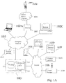
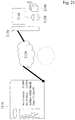
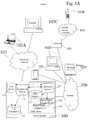
- a network portal system 100 solves the prior art portal limitations by giving users access from whatever device is available at the time, through a single system entry point, i.e., "a portal," to a complete complement of applications, services, and data.
- a portal a single system entry point
- network portal system 100 frees a user from time and location constraints when accessing the complete complement of applications, services, and data.
- a user can access applications and data on network portal system 100 from almost any available device, e.g., any one of portable computer 102A, a mobile telephone 102B, a workstation 102C, a home personal computer (PC) 102D, a personal digital assistant 102E, or an Internet café machine 102F. No longer is a user limited to using either workstations and/or portable computers with specialized software installed, or to using any particular Internet Service Provider.
- network portal system 100 provides the user with comprehensive functionality.
- the user's full range of applications is always available to the user.
- enterprises can easily incorporate existing applications into network portal system 100.
- the user can access multiple data sources via network portal system 100. Different types and formats of data, from different applications, can all be accessed and processed within a single user interface. Further, data from external sources, such as stock quotes from web-based service providers, can be accessed using the same single user interface.
- a user on a vacation overseas suddenly realizes that the presentation her boss is going to deliver the next morning contains a critical error.
- the user drops by an Internet cafe and from any machine 102F at the cafe accesses the presentation via network portal system 100, and makes the necessary corrections using applications written, for example, in a scripting language and/or the C++ programming language even though only a browser is available on machine 102F.
- the user is having dinner at a friend's house, and gets an urgent call saying that a report that can be assessed via network portal system 100 must be revised that evening.
- the revisions will not require much work, but the trip to the office and back is a very unwelcome prospect.
- the friend's PC 102D and the friend's Internet service provider the user works on the report without leaving his friend's home.
- Another user is expecting an important document, but the user has a business appointment outside the office.
- the document arrives by e-mail while the user is in transit.
- the user accesses the e-mail using network portal system 100, reviews the document, and then re-directs the document to the fax machine at the site to which the user is going.
- network portal system 100 is a comprehensive client/server offering that enables users to access their applications, data, and services from almost any device anywhere.
- the applications and data are stored on network portal system 100 and are accessed using a web-top manager 111 in combination with a universal content broker system 112 that includes universal content broker 113.
- web-top manager 111 and universal content broker system 112 are designed as a distributed system that can be spread over multiple host machines, and can run on platforms utilizing any one of the operating systems Solaris, Windows NT/Windows 2000 (server version), or Linux
- the user using a web browser and an Internet connection on any JAVA-enabled system, the user simply logs on to a web server in web-top manager 111, and proceeds as though everything were locally resident on his/her machine.
- JavaVA is a trademark of Sun Microsystems, Inc. of Palo, Alto, CA.
- execution actually takes place on the web server this fact is transparent to the user.
- local services available on a client system including devices like printers and local storage, can be utilized by web server-based components in a transparent manner.
- WAP Wireless Application Protocol
- PDA Personal Area Network
- web-top manager 111 includes a plurality of remote applications, such as office applications that include, for example, a word processing application, a spreadsheet application, a database application, a graphics and drawing application, an e-mail application, a contacts manager application, a schedule application, and a presentation application.
- office applications such as office applications that include, for example, a word processing application, a spreadsheet application, a database application, a graphics and drawing application, an e-mail application, a contacts manager application, a schedule application, and a presentation application.
- office application package suitable for use with this embodiment of the present invention, is the STAROFFICE Application Suite available from Sun Microsystems, Inc., 901 San Antonio Road, Palo Alto, CA. (STAROFFICE is a trademark of Sun Microsystems, Inc.)
- the user accesses and runs a user selected remote application using only a thin-client on the user's device with a lightweight component installed. To the user, it appears as if the remote application is installed on the user device.
- both the data being processed and the remote application are on network portal system 100.
- network portal system 100 allows users to incorporate their own applications and data seamlessly, as well as to give the users access to information from external service providers.
- Network portal system 100 can be a user's sole entry into the world of information.
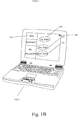
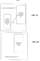
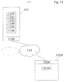
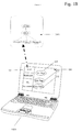
- access to external service providers is provided through portlets, where each portlet accessible by a user is represented on the display of the user device by an icon or perhaps a text name.
- a display 150 of user device 102A includes icons 120 to 122, each of which is associated with a different portlet.
- a portlet icon when a portlet icon is selected on a user device, the content associated with the portlet is retrieved by network portal system 100 and automatically transformed by network portal system 100 into data that can be displayed by that user device.
- a particular user device is not limited to accessing content in a format identical to that associated with the user interface in use on the user device. Consequently, the user's ability to access a wide variety of content sources independent of the characteristics of the particular user device is further enhanced with the portlets of this invention.
- network portal system 100 eliminates prior art limitations on a single user system on a network accessing content on any desired provider system that is coupled to the network.
- the functionality described above is provided using a browser executing on a client device 102i (See Fig. 1A), e.g., any one of devices 102A, 102C, 102D and 102F.
- the browser communicates with web-top manager 111 via a network, e.g., enterprise network 103, Internet 106, or a combination of the two 103/106.
- a user of client device 102i causes the browser to transmit a request via the network to web-top manager 111.
- the request includes the type of document or service requested, the type of client device 102i that is making the request, the type of the browser executing on client device 102i, and a protocol that is typically part of a uniform resource locator (URL) included in the request.
- URL uniform resource locator
- web-top manager 111 Upon receipt of the request, web-top manager 111 processes the request. If the request is for content that is provided by one of universal content providers 101A to 101C that are registered with universal content broker 113, web-top manager 111 issues a call to universal content broker 113. If the content is available through a portlet, the request is passed to a portlet manager, which in one embodiment, as described more completely below, is a servlet executing on web-top manager 111.
- universal content broker 113 In response to a call from web-top manager 111, universal content broker 113 returns a handle to the requested content to web-top manager 111. Web-top manager uses the handle in retrieving the content. However, before the content is returned to user device 102i, in one embodiment, the content is converted to a page or pages that can be displayed and/or processed by the thin-client on the user device.
- web-top manager 111 includes a user interface, which is defined via different XML, HTML or WML templates and/or stylesheets.
- Web-top manager 111 selects a template, or stylesheet using the information transmitted in the request from client device 102i.
- the template, or stylesheet selected by web-top manager 111 is used to present content in the form required by client device 102i.
- web-top manager 111 upon retrieving the requested content using the handle provided by UCB 113, web-top manager 111 loads, for example, a template and fills in all user specific content in the template using the retrieved content.
- the completed template is transmitted to client device 102i for display.
- web-top manager 111 retrieves a stylesheet and uses the stylesheet to transform the content into a format that can be displayed on client device 102i.
- the retrieved content is processed by a dynamic data conversion service.
- the dynamic data conversion service generates a dynamic data filter that includes a chain of partial filter adapter components.
- the dynamic filter converts the original retrieved content from a first format into a second format such that the information can be extracted and placed in the template or transformed using a stylesheet.
- the generation of dynamic data filters facilitates processing a broad range of content with differing formats by network portal system 100.
- the client request was for content provided by a registered content provider or for content available via a portlet.
- the request could be to launch a remote application in web-top manager 111.
- web-top manager 111 prepares a template that includes, for example, an HTML page that includes JAVA Bean and returns the page to the browser.
- the user Upon execution of the JAVA Bean, the user has full access to the capabilities of the remote application that is executing on network portal system 100 just as if the complete application were executing on client device 102i. If the user requests that the remote application process specific content, e.g., a text document, or perhaps a spreadsheet, the request is sent by the application to universal content broker 113 that functions as described above.
- specific content e.g., a text document, or perhaps a spreadsheet
- network portal system 100 may be implemented in a distributed environment, in which the text processing application executes on one computer under a first operating system and the spreadsheet application executes on another computer under a second operating system. Alternatively, both applications may execute on the same computer, but the text processing application is written in one programming language and the spreadsheet application is written in a different programming language.
- the text processing application is executing within a first execution environment, and in response to the user request the text processing application issues a call to the spreadsheet calculator of the spreadsheet application that is executing within a second execution environment that is different from the first execution environment.
- an execution environment contains all objects, which have the same binary specification and which lie in the same process address space.
- the execution environment is specific for a computer programming language and for a compiler for that computer programming language.
- the call from the text processing application is directed to a proxy in a bridge that converts the original call to a call to the desired service in the second execution environment.
- the proxy dispatches the converted call to the desired service in the second execution environment.
- the results are returned to the proxy in a bridge that in turn converts the results from the second execution environment to the first execution environment.
- the converted results are returned to the text processing application for use.
- the user has accessed functionality distributed within network portal system 100 using only what appears to the user as a single application executing on client device 102i.
- the ability to transparently access applications and services in different execution environments greatly increases the services and functionality that can be provided to a wide variety of client devices.
- network portal system 100 not only includes a dynamic data format conversion capability for content, but also a dynamic dispatch functionality for accessing services in different execution environments. These functionalities are optional, but when included in network portal system 100, the functionalities transparently expand the services and capabilities available to client device 102i that has only a browser installed.
- network portal system 100 Another service provided by network portal system 100 is a hierarchy service, which in one embodiment is one of the universal content providers accessible via universal content broker 113.
- a hierarchy service which in one embodiment is one of the universal content providers accessible via universal content broker 113.
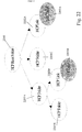
- each time the user wanted to access e-mail message, HTTP links, or a stored file the user had to access a different program element that in turn generated a display associated with that program element, e.g., displays 200A to 200C.
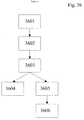
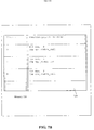
- the hierarchy service in network portal system 100 returns a page that results in a virtual hierarchy 210 that is displayed as illustrated in Figure 2D.
- the hierarchy service organizes the user's data in an abstract manner whether the data is the user's directory, mail accounts, or bookmarks. As illustrated in Figure 2D, the hierarchy service orders all user content in a virtual hierarchy 210, which is represented in the user interface on client device 102i. Virtual hierarchy 210 is browse-able and customizable, gives the user a homogenous view of the entire user's content on network portal system 100.
- virtual hierarchy 210 includes a root node 230 and three other nodes 231 to 233. Initially, only root node 230 may be displayed and then when the user selects root node 230, nodes 231 to 233 are displayed. If the user then selects one of nodes 231 to 233, the user is presented with the hierarchy indicated by the broken arrow.
- virtual nodes generated by the hierarchy service act as UCB content nodes. So the resulting hierarchy, sometimes referred to as a content tree, consisting of the virtual nodes and protocol specific nodes, as illustrated in Figure 2D, can be processed in a transparent manner. This means, that a generic explorer or all kind of viewers can access the whole content tree without special knowledge about the underlying protocols or implementation details of the specific providers associated with the various virtual nodes.
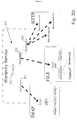
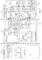
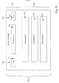
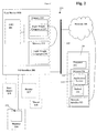
- Figure 3A is a high-level block diagram of one embodiment of network portal system 100, which provides office productivity services.
- Network portal system 100 is highly independent of client systems 102i, where i is A, C, D and F in Figure 1, and 102j where j is B in Figure 1, which are used to access services and/or content using network portal system 100.
- Support of several client devices with very different hardware and software capabilities mandates that the overall architecture and the core components of network portal system 100 are flexible enough to minimize the effort of integrating support for new client devices.
- content provider systems, servers, client systems, networks and similar terms are utilized with respect to computer systems and interconnections of both such systems and individual units, and may include both the hardware and software typically utilized in such systems.
- content denotes any information, which may be of any kind in any physical or logical format, which can be transmitted over a communication network.
- content may be any information that is stored in the form of electronic files, typically residing on a server, or content may be generated by execution of a particular application program.
- Communication standards i.e., protocols, which define the way of communication between two systems are used herein, in one embodiment, as content provider identifiers.
- An example, of a content provider identifier is a URL scheme that is described more completely below.
- a MIME type is an example of a definition of a type of content. In general, the content type determines the raw data format of the content. As explained more completely below, the content identifier is used to select a content provider that supplies, creates, or acts on content having a raw data format.
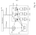
- Network portal system 100 is divided into three tiers, e.g., a client tier 301, a middle tier 302, and an information system tier 303 that in turn are each divided into several subsystems.
- client tier 301 includes a computer system 102i and a wireless application protocol (WAP) device 102j.
- Middle tier 302 is web-top manager 111.
- Information system tier 303 includes universal content broker system 112 that in turn includes a configuration server 336 with associated database(s) 337, and universal content broker 113 that utilizes a plurality of universal content providers 331 and universal content broker (UCB) content 332.
- a hierarchy service 335 is one of universal content provider 331 and so is sometimes called hierarchy content provider 335.
- client tier 301 In general, all hardware and software resources, which reside on users' devices, are part of client tier 301. These resources may vary from a mobile phone 102B with WAP support, to an internet kiosk 102F with a HTML browser, to a desktop PC 102D with an installed word processor and locally stored documents.
- client devices 102i and 102j In Figure 3A, the subsystems illustrated within client devices 102i and 102j are those that are typically used to interface with network portal system 100.
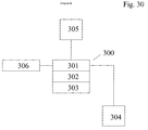
- Client device 102i in one embodiment, includes a browser 304 that utilizes the HyperText Markup Language (HTML) and a JAVA Virtual Machine (VM) 308 and executes JAVA scripts 309.
- client device 102i can include one or more applications 305.
- HTML HyperText Markup Language
- VM JAVA Virtual Machine
- client device 102i can include one or more applications 305.
- one of the novel features of this invention is that a user can access, via browser 304, an application in remote applications 310 or any other service provided by network portal system 100.
- Any components needed to interface with the remote application and/or service are downloaded dynamically to client device 102i, when the components are needed.
- the complexity of these downloaded components can differ extremely depending on the capabilities of client device 102i and the requirements of the remote application and/or requested service.
- the download component can be a simple WML page, a set of HTML pages, which interact by JAVA script calls, or a complex JAVA applet.
- a virtual class library for the particular user device, or perhaps a complete application may be downloaded.
- a thin client is a simple HTML page.
- network portal system 100 receives input requests and generates output responses using a thin client, because this minimize processing requirements on the client and minimizes the data quantity transferred over the network.
- JAVA programming language JAVA scripts
- HTML HyperText Markup Language
- equivalent functionality can be generated using any desired programming language, for example, the C programming language, or the C++ programming language can be used to develop browser add-ins.
- XML extensible markup language
- WAP client device 102j includes a wireless markup language engine 306 that executes wireless markup language scripts 307. WAP client device 102j communicates with a gateway 105 that interfaces device 102j with web-top manager 111 in one embodiment.
- middle tier 302 is web-top manager 111.
- Web-top manager 111 includes a web server 320.
- Web server 320 includes a desktop servlet 322 coupled to a presentation and logic system 323 that provides a presentation and logic service, and optionally, a portlet manager 321 that interacts with a plurality of portlets 324 that in turn are each a servlet.
- the number of portlets included in web server 320 is optional and can vary from zero to any desired number.
- reference numeral 323 is used for both presentation and logic system and the presentation and logic service for convenience.
- An important aspect in building a flexible, extendable and robust network portal system 100 is to bring in one or more abstraction layers between client tier 301 and information system tier 303 to reduce dependencies of core components in information system tier 303 to specialized front ends.
- This abstraction in general, is done by presentation and logic service 323 in middle tier 302. As explained more completely below, presentation and logic service 323 provides functionality in an application oriented way and hides implementation details of information system tier 303.
- a first embodiment of presentation and logic service 323 uses a plurality of providers and adapters.
- the adapter forms a link with universal content broker 113 and universal content broker content 332 to retrieve data, and an adapter extracts information from the data and builds a page that can be returned for display to the user device.
- a second embodiment of presentation and logic service 323 uses controller servlets, JAVA beans as models, and JAVASERVER PAGES objects as views.
- a JAVA bean forms a connection with universal content broker 113 to retrieve data.
- a servlet extracts the desired information from the data and inserts the information in a JAVASERVER PAGE object that in turn is used to generate a page that can be returned for display on user device 102i or 102j.
- middle tier 302 A second task of middle tier 302 is to provide access points for all kinds of clients in client tier 301, to manage user sessions for clients in client tier 301, and to provide specialized functionality to different kinds of clients in client tier 301. As explained more completely below, this specialized functionality is provided by middle tier 302 (i) supplying dynamically generated pages that can be displayed on the user device, e.g., HTML/WML/XML pages, (ii) linking requests from components in client tier 301 to actions on data objects, or (iii) hosting one of a plurality of remote applications 310, which are executed on a server machine for a client in client tier 301, but the user interface for the application is displayed on client device 102i.
- dynamically generated pages that can be displayed on the user device, e.g., HTML/WML/XML pages
- linking requests from components in client tier 301 to actions on data objects or
- hosting one of a plurality of remote applications 310 which are executed on a
- the third tier, information system tier 303 includes configuration server 336 in universal content broker system 112.
- Information system tier 303 also includes universal content broker 113 that utilizes universal content providers 331 including hierarchy content provider 335 and universal content broker content 332.
- Information system tier 303 is a server-side tier.
- Information system tier 303 is the users' informational backbone, which, in the prior art, was typically housed in various databases in traditional legacy system architecture. (The users here are the clients in client tier 301 that were referred to above.)
- Network portal system 100 consolidates all resources under a single content manager, e.g., universal content broker 113, which allows a wide variety of data types to be accessed via a unified interface.
- more than one data source can be used by or connected to network portal system 100.
- data can be stored in local file system 544 (See Fig. 5), on an HTTP server 543, on a FTP server (not shown), in an e-mail account on IMAP server 542, or on a NFS server (not shown).
- One task of universal content broker 113 is to standardize the access to different data sources.
- universal content broker 113 provides a range of functions for querying, modifying and creating data content.
- the use of different data sources is transparent for a portal user, i.e., the user of any user device coupled to network portal system 100.
- hierarchy content provider 335 organizes the different sources in form of a hierarchical structure. For example, see Figure 2D.
- a user can classify the data sources by using user-defined folders and then browse through the content using an explorer. With the explorer and the hierarchical presentation of all the user's information available through universal content broker 113, the user does not have to think about which protocol has been used or what the type is of the particular data in accessing the data. As indicated above, data is accessed by going through a standardized interface that includes the explorer capability.
- Universal content broker 113 functions, in one embodiment, as a framework containing a range of elements and services for use with different data sources. Specifically, universal content broker 113 administers a plurality of universal content providers 331. Each universal content provider encapsulates the details of the different protocols and data sources available through that provider. In one embodiment, a set of default universal content providers 331 allows access through FILE, HTTP, FTP, IMAP, POP3 and SMTP protocols. A portal operator can implement additional content providers so that in-house information services can be integrated into network portal system 100. For example, this could be a connection to a SAPTM system.
- the data content in UCB content 332 is encapsulated in content objects.
- the content objects implement, among other things, an interface for querying general information, as described more completely below.
- the interface can be used to call up different properties such as MIME type, URL, etc.
- each content object provides a series of commands for accessing the actual data by implementing other interfaces.
- the commands available in each individual content object depend on the data type. Commands such as an open command can be used in almost all content types, whereas a createFolder command would have little use in a pure text object.
- content objects can contain different kinds of data.
- a content object can encapsulate a file, an e-mail, a basic HTML page or a system folder.
- each content object sometimes called content, implements a standard set of interfaces. These interfaces are described in detail below, but a brief summary of their function is given here.
- the interfaces include functions for calling content type and any commands that can be run on the content.
- Typical examples are commands such as "open” or "delete”.
- a developer can define further commands depending on the content type. For example, an "update” command can be used on a POP3 inbox. There is an additional function available for terminating a command.
- the interfaces also provide functionality to register different listeners that pass on alterations made to data to interested applications in the form of events. This type of message can result from such events as deletion or simply by changing content properties. If the content object is a folder, additional events can be sent when new sub-content has been inserted or removed.
- Each content object has a range of properties that can be read and re-set by an application.
- content has to have certain properties, including title, MIME type and an id, for example.
- optional properties can be set if required. This could cover such information as the date the content was created or modified or the saving of passwords.
- Content node hierarchies can be built for content objects such as an IMAP account or a file system as illustrated in Figure 2D. In these situations, a parent-child relationship exists between the different content objects. To enable access not only to parent nodes but also to child nodes, the content objects implement additional interfaces that also allows new nodes to be created and inserted.
- Universal content providers 331 make access possible to the different data sources in UCB content 332.
- Each content provider implements an interface, which facilitates access to data through a Uniform Resource Identifier (URI).
- URI Uniform Resource Identifier
- the structure describes the protocol used for accessing each of the data sources, sometimes called the URL scheme, or more generally protocol scheme, or content provider identifier. If an IMAP account source were used, the content provider identifier would be "imap", if a FTP server is used, then “ftp" would appear as the content provider identifier.
- Universal content broker 113 administers universal content providers 331. As soon as a client requests particular content, in this embodiment, web server 320 addresses UCB 113 and passes on the corresponding URI. The UCB 113 analyzes the URI to determine the content provider identifier so that UCB can find the appropriate universal content provider on UCP registry 341. The task of loading the requested data is delegated to this provider. Neither, the user of user device 102i nor web server 320 needs to know specific details about the protocol or data source. The content provider carries out all of the necessary steps. The protocol or data source details are thus hidden from the client.
- the requested data is loaded and transferred to the client, in this case web server 320, as a content object.
- the content object encapsulates the requested data.
- the client can now run commands on the content object, to load or edit the data, for example.
- the internal data structure is hidden from the client, which means that it is possible to treat data from different sources in the same fashion. Accessing an e-mail account is therefore no different to accessing a local file system.
- Figs. 2A and 2B Some prior art content types can have a hierarchical structure. See Figs. 2A and 2B. This applies to content objects such as those created by a file provider or IMAP provider. Users can browse through the different content objects or insert new content nodes into the hierarchy or delete existing ones. With other providers, such as HTTP, there is no relationship between the different contents. Users must know the exact location (the URL) to be able to access specific content. In the prior art, accessing this type of data by browsing with an explorer was not possible.
- hierarchy content provider 335 allows a user to classify any kind of content type in a virtual hierarchy as illustrated in Figure 2D. Users can define custom folders which themselves can contain folders or links to any content. Users can adapt this classification to match their requirements and taste. All of the settings made are stored in a persistent fashion and are, therefore, available when the user logs into network portal system again.
- Hierarchy content provider 335 provides portal users with a standard, expandable view of the different data in network portal system 100. The users can browse through the different contents with an explorer, without having to keep in mind which protocol is being used or what the content type is.
- a UCB process which is described more completely below, is created for each user on-demand on a server.
- a daemon is used to start and end processes on the server. The daemon also builds connections between components on network portal system 100.
- the daemon could be used in conjunction with load balancing. In this case, the daemon acts as a contact for all server components, while client components contact a part of the load balancer to determine on which of a plurality of servers to start a requested process.
- universal content broker 113 uses the entries in configuration server 336 to determine which content provider (UCP) is available in the system for which protocol and then enters the corresponding details into an internal table, sometimes called a provider registry. If necessary, user-specific settings are taken into account, as in the case of a hierarchical classification of the various data sources.
- UCP content provider
- universal content broker 113 delegates the requests to the appropriate provider. This then takes care of the actual running of the data access. In this situation, universal content broker 113 can be seen as the contact and middleman.
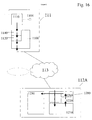
- data stored locally on a client can only be loaded through a web browser and so local data cannot be accessed by using universal content broker 113.
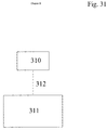
- an additional universal content broker 113C maybe implemented on client device 102i.
- client universal content broker 113C can be hinged onto server universal content broker 113 as an additional universal content provider.
- a file content provider could then be registered on the client universal content broker 113C, for example, so that the local file system can be accessed.
- client universal content broker 113C when the user is not connected to the network, the user can use client universal content broker 113C when using applications 305.
- client universal content broker 113C When the user is connected to the network a single component 390, running on the client side synchronizes client universal content broker 113C with server universal content broker 113.
- Synchronizing component 390 synchronizes messages in user mailboxes, files that were edited on local machine 102i, and files that were, say, accessed from a browser and edited directly on network portal system 100. Synchronization of content also applies to multi-user operations, in which a number of people may be operating on various areas of the content. In this situation, collision prevention is also provided.
- All of the settings in network portal system 100 are stored by configuration server 336. This includes user-specific, application-specific and device-dependent configurations.
- the central storing and standard structure facilitate system maintenance. Instead of monitoring the status of various configuration files, an administrator views and modifies the settings at a central location when necessary. This central storing also allows "Roaming Profiles". A user can log into network portal system 100 through different computers from any location, as described above. Irrespective of where a user is, the user always finds their usual work environment with the custom settings.
- configuration server 336 By using configuration server 336, different kinds of information are stored in an ordered manner so that the information can be accessed quickly.
- configuration server 336 contains entries for the user accounts, which contain the user name, password, home directory, and similar information. Configuration server 336 also holds various entries used to initialize applications.
- Each component of network portal system 100 can store and load persistent data in configuration server 336. Entries for services that have been initially integrated into network portal system 100 are stored in the configuration server 336 as well.
- All of the entries are stored in hierarchical form in key-value pairs. As explained more completely, below a configuration tree contains separate branches for this purpose, which can be used for different users or the various user devices.
- the configuration tree is described through a Document Object Model (DOM) based on XML (Extended Markup Language).
- DOM Document Object Model
- XML Extended Markup Language
- Alterations to the DOM tree are carried out by transactions, which include inserting new nodes or new key-value pairs describing user preferences. This also covers such things as modification of individual entries or deletion of an entire subtree as the entries are no longer needed.
- Configuration server 336 also contains different mechanisms for querying the status of transactions or registering different listeners that are notified when alterations are made to configuration service elements and that in turn notify the applications affected.
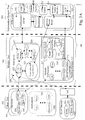
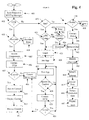
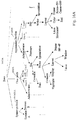
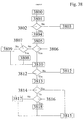
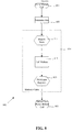
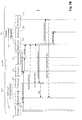
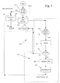
- Figure 4 is a high-level process flow diagram for one embodiment of network portal system 100.
- a user inputs a request via a browser 304 executing on client device 102i in transmit request to web-top manager operation 401.
- Information in the request identifies whether the request is for content available through universal content broker 113, for content available from an external provider, e.g., through one of plurality of portlets 324, or for a service in remote applications 310 that is supported by web-top manager 111.
- the request from browser 304 is transmitted over a network to web-top manager 311 in transmit request to web-top manager operation 401.
- the transmitted request includes the type of document or service requested, the type of client device 102i that is making the request, the type of the browser executing on client device 102i, and the communication protocol that is typically part of a uniform resource locator (URL) included in the request.
- URL uniform resource locator
- web server 320 determines how to process the request. It should be noted that web server 320 may require various user authentications before access to web server 320 itself, or before access to any information accessible via web server 320 is granted. The particular techniques used for such authentication as well as the various levels of authentication that may be used are not essential to this invention and so are not considered further.
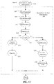
- Web server 320 determines whether the request is for universal content broker 113 in UCB Check operation 402. If the request if for universal content broker 113, check operation 402 transfers to provider check operation 403 and otherwise to application check operation 420.
- desktop servlet 322 uses presentation and logic service 323 to determine whether there are components available within service 323 to access universal content broker 113 for the type of information requested, e.g., for the MIME type of the information.
- service 323 may access a user configuration file that was generated using configuration server 336 to determine whether components within service 323 have been instantiated for accessing universal content broker 113 for the type of information requested and for this user. If such components do not exist, in one embodiment, service 323 accesses a registry of factories to determine whether components can be instantiated for accessing the requested type of content, and if so uses the appropriate factory to instantiate the necessary components within service 323.
- check operation 403 transfers to access components operation 405, and otherwise transfers to return provider error operation 404.
- return provider error operation 404 desktop servlet 322 generates an HTML page that is returned to client device 102i, which informs the user that the requested content is unavailable.
- service 323 passes the request to the component within service 323 that supports the requested content.
- service 323 For example, assume that the user of client device 102i sent a request to network portal system 100 for the retrieval of content constituting a message on an IMAP server with an associated property.
- the content has an associated property value UID set to 3.
- desktop servlet 322 passes the request including this URL to the IMAP components in service 323 that process IMAP requests.
- the IMAP components in turn pass the request including the URL to universal content broker 113 in contact UCB operation 406.
- universal content broker 113 searches a registry of universal content providers 341 for the content provider associated with the URL. If a content provider for the requested content is found in a plurality of universal content providers 331, universal content broker 113 passes the request to the universal content provider that in turn retrieves the requested data, if necessary and returns a handle to the requested content in universal content broker content 332, and otherwise an error message is returned. Notice that the user device is not required to have software installed, or the hardware capability required to access the content via the particular protocol required. These details are delegated to the universal content provider. To this point the only requirement on the user device is to generate a request that can be processed by web-top manager 111.
- Content check operation 407 determines whether a handle or an error message was returned by universal content broker 113. If a handle to the requested data in UCB content 332 is returned processing transfers to access content operation 409 and otherwise processing transfers to content unavailable error operation 408. In error operation 408, the components within service 323 that are processing the user request generate a page that includes the error message and return that page to the user device for display.
- the components within service 323 processing the request use the returned handle to obtain the raw data from UCB content 332.
- This data is in a format associated with the particular universal content provider. Accordingly, as explained more completely below, in operation 409, information is extracted from the raw data and placed, in this embodiment, in a template associated with the user device that issued the request.
- there is another set of content templates for each type of content e.g., one set for an e-mail, another for an IMAP folder, and a third for a file system folder.
- there is a template for each class of user device based on user device capabilities.
- the template selected from these sets i.e., the template associated with the user device, is selected based upon information in the request from the user device, as explained more completely below.
- the content that is accessed is in a raw data format.
- Information is extracted from the content, as explained more completely below, and inserted in the template that represents a page that can be displayed on the user device, or alternatively that can be used to generate a page that can be displayed on the user device. In either case, service 323 returns a page to the user device upon completions of operation 409 that includes the requested content.
- the user device Upon receipt of the response to the issued request, the user device displays the page that was returned in display content operation 410.
- the user can manipulate the displayed data, e.g., delete an e-mail message, and forward the content to an output device.
- process content 411 the user device issues another request in the form of an HTTP POST request, and this request is processed via operations 402 to 410 as described above.
- the operations performed on UCB content are not limited to retrieving and saving content. Properties of content can also be changed, added, updated, or perhaps deleted through universal content broker 113 and the appropriate universal content provider.
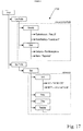
- the request is passed to application/service check operation 420. If a user of device 102i issued a request to use remote applications 320 over network 103/106 to web server 320. The transmission of the request over the network 103/106 is performed according to a predetermined transmission protocol. In response to the request from user device 102i, web server 320 determines whether the request is for a service or application in remote applications 310 and if the request is for such a service or application, processing transfers to lightweight component available check operation 421 and otherwise to portlet check operation 440.
- Lightweight component check operation 421 determines whether a lightweight remote visualization component 311 needed to run the requested service/application is installed on user device 102i. This can be done, for example, by accessing a user configuration file on web server 320, or alternatively by executing a process on web server 320 that accesses the user device and determines whether the lightweight component is installed. If the required lightweight remote visualization component is installed on user device 102i, check operation 421 transfers to login operation 425 and otherwise to device capability check operation 422
- Device capability check operation 422 determines whether user device 102i can execute and use the lightweight remote visualization component 311, e.g., is there a lightweight component 311 available for the general type of user device 102i, and is the operating system, processor, and memory of specific user device 102i sufficient to execute and support lightweight component 311.
- This information may be included in the initial request, a process on web server 320 may communicate with user device 102i to obtain the information, the information may be retrieved from configuration server 336, or alternatively, the request may include an identifier that is used to access some other database to determine the capabilities of user device 102i.
- processing transfers to download component operation 424 and otherwise to return error operation 423.
- Return error operation 423 sends an appropriate error message to user device 102i to inform the user of the incompatibility between the requested service/application and user device 102i.
- Download component operation 424 downloads, and installs if necessary, lightweight component 311 on user device 102i.
- lightweight component 311 is available on user device 102i.
- a connection is established over network 103/106 to a daemon executing on web server 320.
- the daemon returns a handle to a daemon service factory to the lightweight remote visualization component on user device 102i.
- the lightweight remote visualization component on user device 102i Upon receipt of the handle to the daemon service factory, the lightweight remote visualization component on user device 102i issues a request to the service factory to initiate execution of a login service on web server 320. Upon activation of the login service in login operation 425, the lightweight remote visualization component on user device 102i transmits a user identification, a password, and options for the service/application, i.e., a runtime environment component, in remote applications 310 to the login service. The login service on web server 320 in operation 425 validates the user login and transfers to initialize application operation 426.
- the service/application i.e., a runtime environment component
- daemon and login service are described with respect to accessing a service/application.
- a daemon process and login service are used to initiate each service supplied by network portal system 100 and so typically are also included within other branches of Figure 4.
- a start application operation within operation 426 activates a service factory for remote applications 310, e.g., runtime environment components, on web server 320 and returns a handle to this service factory to the lightweight remote visualization component on user device 102i.
- the lightweight remote visualization component on user device 102i issues a request to the runtime environment components service factory to start an infrastructure generation service.
- the service factory In response to the request, the service factory, executing on web server 320, activates the infrastructure generation service, and returns a handle to this service to the lightweight remote visualization component on user device 102i.
- the lightweight remote visualization component on user device 102i issues a request to start the infrastructure generation service, and passes a handle to a client factory to the service.
- the lightweight remote visualization component on user device 102i next issues a request to create a visual infrastructure on web server 320 for processing the visual portion of the user interface.
- the infrastructure generation service In response to the request from the lightweight remote visualization component on user device 102i, the infrastructure generation service first issues a request to the client factory on user device 102i to create a remote frame window, and then this service creates a corresponding server window object on web server 320.
- the server window object queries the remote frame window on user device 102i to determine the fonts, display parameters, etc. on user device 102i.
- the server window object can obtain identifier information from user device 102i and then use this identifier information to access a database that includes the display capabilities of device 102i via configuration server 336.
- the infrastructure generation service Upon completion of the queries, in a create environment infrastructure operation, the infrastructure generation service creates a frame object that controls the environment of the server window object and creates a direct connection between the frame object and lightweight remote visualization component on user device 102i. Operation 426 transfers to run application operation 427. At this point, a direct connection is established between user device 102i and the service/application in remote applications 310.
- lightweight remote visualization component 311 sends a command to the frame object to load a particular document in the service/application.
- the frame object initiates a request to UCB 113 for the document.
- Check operation 428 passes the request to contact UCB operation 429.
- operate on content check operation 428 determines whether the user has issued such an instruction to save, retrieve, or replace content, or to act on a property of the content. If an instruction to operate on content was not issued processing returns to run application operation 427, and otherwise to contact UCB operation 429.
- check operation 427 is not continually performed, but rather typically is performed by an event processor in response to a specific user input event.
- operation 429 is similar to operation 406 that was described above.
- Operation 429 transfers to content check operation 430 that functions in a manner similar to operation 407.
- content check operation 430 universal content broker 113 determines whether the operation requested in the instruction is permitted, e.g., is the content available through universal content broker 113, and if the content is available, is this user permitted to perform the operation requested. If the answer is no to either of these checks, processing transfers to return content error operation 408, which in turn notifies the user that the requested operation on the content cannot be performed. Otherwise, the application is provided access to the content and permitted to perform the operation on the content, which in this case is loading the document.
- the user did not have to worry about the specific location at which the content was stored. To the user, the content appeared as if the content was on user device 102i. This provides the user with access to content independent of the location of the user, e.g., see the above example where the user was at a friend's home.
- the service/application After the document is loaded, the service/application reads the loaded document, and generates a display layout that is sent to the server window object.
- the server window object sends the display layout to the remote frame window in the lightweight remote visualization component on user device 102i.
- the remote frame window generates commands to a device dependant graphic layer, e.g., the JAVA AWT that in turn generates the user interface on a display screen of user device 102i.
- user device 102i has limited input/output capability, the user may be able to only read the document, or perhaps direct the document to a local output device if the remote service/application includes such a capability, e.g., a capability to write to a local printer or to write to a fax printer.
- the remote service/application includes such a capability, e.g., a capability to write to a local printer or to write to a fax printer.
- the user can utilize the full functionality of the service/application. For example, if the user utilizes a mouse to scroll down in the document. The scroll action is interpreted by the windowing environment on user device 102i and a scroll command is set by the windowing environment to the remote window frame of the lightweight remote visualization component on user device 102i.
- the remote window frame sends a scroll command over network 103/106 to the server window object on web server 320.
- the server window object processes the event received and generates an application event that in turn is processed by the service/application.
- the application does a re-layout based on the scrolling, and redraws the display in the server window object that in turn sends a redraw command to the remote frame window on user device 102i.
- the transmissions over network 103/106 between lightweight remote visualization component 311 and web server 320 are encrypted according to known technologies. Further, in another embodiment, digital signatures are used to provide certification of the request mechanism being established on the client for this runtime environment component services system.
- the size of the lightweight remote visualization component on user device 102i does not increase with the number of accessed runtime environment components of the implementation server framework. This introduces the ability to offer runtime environment components, which expose only services designed for a special purpose and hide the complexity of the implementation framework. A more complete description of embodiments of the using services/applications on network portal system 100 is described CHAPTER C below.
- the lightweight remote visualization component on user device 102i maps visual display instructions from an application executing on web-top manager 111 to a platform dependent graphic layer that in turn generates a user interface on a display screen of the user device.
- the user interface for the remote application is similar to the user interface that the user would see if the application actually were executing locally on device 102i.
- the interfaces may not be identical if user device 102i has limited input/output capability.
- client device 102i the only restrictions on client device 102i are that the device must have the capability to execute a browser, the capability to execute the lightweight remote visualization component, and the capability to provide the input operations required by the application or service. There is no requirement that client device have preinstalled specialized client/server software for each application or service that is available via web-top manager 111. Consequently, the requirement for updating the specialized client/server software on each client device each time a change is made to an application or service has been eliminated.
- a user initiates a request on a user device 102i by selecting a portlet identifier, e.g., an icon, for example, that represents a particular instance of data that is accessible via a particular portlet on web server 320.
- a portlet identifier e.g., an icon, for example, that represents a particular instance of data that is accessible via a particular portlet on web server 320.
- an icon representing a portlet is only selectable for display on display screen 150 (Fig. 1B) if the data provided by the portlet may be presented by user device 102i.
- a portlet which provides data with the MIME type image/jpeg, would not be available for selection for display on the display screen of user device 102i.
- this pre-selection of portlets offered to the user is made by a comparison of the MIME types supported by the user device and the MIME type of data for each of the portlets.
- CHAPTER D A more detailed description of embodiments of a process used to select portlets that may be accessed by user device 102i is described in CHAPTER D below.
- the request transmitted in send request operation 401 includes at least a description of the requested data. Such a description may be, for example, the URL of the data.
- the request typically also includes the MIME type or types supported by the user device, e.g., wireless application protocol (WAP) for mobile phone 102j.
- WAP wireless application protocol
- the request may also include either or both of the identity of the user device and the identity of the user of the user device.
- the request may further include a command, such as channel, load, save, or article. See European Patent Application entitled " A COMPUTER-BASED PRESENTATION MANAGER AND METHOD FOR INDIVIDUAL USER-DEVICE DATA REPRESENTATION," of Ralf Hofmann et al.
- Portlet check operation 440 analyzes the request from user device 102i, sometimes referred to as the original request, to determine whether this request has to be processed by portlet manager 321.
- Check operation 440 can be implemented in various alternative ways. In one embodiment, deployment descriptors as defined in the JAVA 2 Enterprise Edition are used and checked in operation 440 to determine where to direct the user request.
- the JAVA 2 Platform Enterprise Edition Specification, v1.2, Sun Microsystems, Inc., Palo Alto, CA (1999) and the JAVA Servlet Specification , v2.2, Sun Microsystems, Inc. Palo Alto, CA (1999) are incorporated herein by reference to show the level of skill in the art. Based upon the deployment descriptors, if the request is a portlet processing transfers to contact portlet operation 441 and otherwise processing transfers to error operation 450 that returns a page with an illegal operation error to user device 102i.
- Portlet manager 321 may be implemented in software within web server 320, or may be installed on a separate computer system, which is connected or connectable to web server 320. In one embodiment, portlet manager 321 is implemented as a servlet that executes on web server 320.
- portlet manager 321 is not continually executing on web server 320, and so if a request is forwarded to portlet manager 321 in contact portlet operation 441, portlet manager 321 is started and then the request is forwarded to portlet manager 321 for processing.
- Portlet manager 321 forwards the request to the appropriate portlet.
- the forwarding of the request to a specific portlet completes contact portlet operation 441.
- the portlet retrieves the data in retrieve data operation 442, and processing in portlet manager 321 transfers to a MIME check operation within identify user type operation 443.
- the request from the user device contains information about the presentation requirements of the requesting user device, or contains information about the identity of the user device, or contains both. If the request contains one or more MIME types processing transfers to a get MIME type from request operation within operation 443 and otherwise to an identity check operation within operation 443.
- portlet manager 321 extracts a list of MIME types supported by the user device from the request including a preferred MIME type, if a preferred MIME type is specified.
- the get MIME type from request operation transfers to the identity check operation.
- portlet manager 321 determines whether the request included identification information. If identity information is included, processing transfers to a get identity from request operation and otherwise to retrieve scheme operation 444. The get identity from request operation retrieves the device identification from the request and transfers to retrieve scheme operation 444.
- retrieve scheme operation 444 portlet manager 321 uses the information extracted from the request to retrieve a presentation scheme for the user device from a plurality of presentation schemes stored on storage unit accessible by web server 320.
- An example of a presentation scheme is an XSL style-sheet for converting the MIME type of the retrieved data to a MIME type that can be displayed by user device 102i.
- the retrieved presentation scheme is loaded in a memory accessible by portlet manager 321.
- retrieve scheme operation 444 transfers processing to convert data operation 445.
- a more detailed process flow diagram of one embodiment of retrieve scheme operation 444 is presented in U.S. Patent Application Serial No. 09/xxx,xxx, entitled " A COMPUTER-BASED PRESENTATION MANAGER AND METHOD FOR INDIVIDUAL USER-DEVICE DATA REPRESENTATION," of Ralf Hofmann et al.
- Portlet manager 321 processes the retrieved data using the stored presentation scheme to generate new data that can be displayed on the user device. For example, if the retrieved information is a XML document, the XSL-stylesheet loaded in memory is used to do the transformation. If the retrieved information is e-mail data, a JAVA class is used to extract the data and insert the data for example into a HTML template.
- Convert data operation 445 transfers to return converted data operation 446.
- portlet manager 321 returns the converted data in a HTTP response to web server 320.
- Web server 320 sends the HTTP response to the user device that sent the original request.
- the user device processes the HTTP response, and displays the response to the original request on the user device.
- convert data operation 445 was performed on the same computer running portlet manager 321.
- retrieve scheme operation 444 and convert data operation 445 send the retrieved scheme and retrieved data respectively to another computer system connected to the user device, or the user device itself.
- convert data operation 445 is performed on the another computer system, or the user device, and returned converted data operation 446 is performed only if operation 444 was executed on other than user device 102i.
- portlet manager 321 was able to identify the type of presentation requirements for the requesting user device and retrieve a presentation scheme that converted the type of the requested data to a type that could be displayed on the user device.
- a presentation scheme is not available to convert the retrieved data to a type of data that can be displayed on the user device.
- the user requests a spreadsheet that has a data format specified by the manufacturer of the application that generated the spreadsheet.
- the presentation scheme available for the user device requires an input document in XML. Since the retrieved document in not in XML, the presentation scheme is not useful.
- portlet manager 321 issues a translation request to a filter server 319.
- portlet manager 321 sends a request that includes the MIME type required as input to the presentation scheme for user device 102i, and an address of the requested document to filter server 319.
- This address can be to a memory where the document is stored after being retrieved by a portlet, or a URL to location of the document on the network.
- filter server 319 is able to access the requested document.
- filter server 319 builds a filter that can read the requested document, dynamically convert the read data using a partial filter adapter chain to the new format, and then write the converted data in the new format so that the data can be supplied to portlet manager 321. More specifically, in response to the request from portlet manager 321, filter server 319 via a conversion service 315, in one embodiment, causes a protocol reader to be instantiated and uses the protocol reader to access the requested document to determine the format of the requested data, i.e., the source document data format. With the source document data format and the target document data format, i.e., the MIME type received in the original request, filter server 319 builds a filter for converting the format of source document to the format of the target document.
- filter server 319 passes the request to a conversion service 315 that in turn accesses a filter registry 316 to generate a filter map of partial filter adapters that can be chained together to convert the format of the requested document to the MIME type specified in the request.
- conversion service 315 calls a service to instantiate each partial filter adapter in the map using partial filter adapter library 318.
- Conversion service 315 calls another service to chain the partial filter adapters together using a chaining application programming interface of each partial filter adapter.
- filter server 319 via conversion service 315 constructs a data filter by gluing a protocol read and parser unit to an input end of the partial filter adapter chain and a bit stream printer and protocol writer to an output end of the chain.
- conversion service 315 uses the data filter to process the requested document, e.g., the spreadsheet.
- the data filter generates data with a MIME type that can be input to the presentation scheme that is returned to portlet manager 321, which in turn processes the data as described above.
- filter server 319 utilizes the same generic format independent interface to input the converted data. This allows any one partial filter adapter to be connected to another partial filter adapter without concern for the particular format of the data output by the first partial filter adapter.
- the data filter is used dynamically, which means that the complete data file is not stored in the intermediate formats. Rather, the output from a first partial filter adapter is input to a second partial filter adapter before all the data has been processed by the first partial filter adapter.
- filter server 319 provides information about the dynamic data filter to portlet manager 321, and portlet manager 321 stores a new presentation scheme that includes the dynamic data filter generated by filter server 319, or at least a handle to the dynamic filter, and the retrieved presentation scheme.
- Network portal system 100 in Figure 5 includes all the services and components described above, but for clarity only the components needed to understand this embodiment of service of 323 are illustrated. Also, it is assumed that the request is issued by user device 102i, but the request could also be issued by any of user devices described herein.
- desktop servlet 322 determines whether there is a provider object available to process the user request from operation 401.
- a provider object sometimes called a provider, is associated with a content provider in plurality of universal content providers 331.
- desktop servlet obtains the handle to the provider from user configuration 501.
- desktop servlet 322 accesses a device to provider configuration registry object 602, which in one embodiment is an XML file in which a provider factory for a particular content identifier and user device page type are registered.
- a HTML provider factory 603 and a WML provider factory 604 are registered in device to provider configuration registry 602. Accordingly, based upon the user device page type specified in the request, a provider factory object is instantiated, and in response to the request generates a provider for the content identifier type.
- the content identifier type was IMAP and so a mail provider 605 was instantiated by factory 603 if the device page type was HTML.
- Mail provider 605 is linked to plurality of templates 607 that were described above.
- plurality of providers 523 includes a provider for explorer adapter 502, a provider for document adapter 503, a provider for mail account adapter 504, and a provider for folder adapter 505.
- a different content identifier e.g., a different URL scheme, is associated with each of the providers.
- the particular adapters available to a user are determined by the content available to the user in the user's instance of universal content broker 113.
- plurality of adapters 515 are provided for a particular user by an authentication infrastructure, which maps the user's HTTP session on web server 320 to the users' instance of universal content broker 113, and creates plurality of adapters 515 that are bound to this instance of universal content broker 113.
- plurality of adapters 515 is implemented using adapter classes that are instantiated and executed on the JAVA Virtual Machine in web server 320.
- Each provider in plurality of providers 523 accesses the user's content for that provider, which is stored in information system tier 303, via the corresponding adapter.
- the user of client device 102i sent a request to network portal system 100 for the retrieval of content constituting a message on an IMAP server 542 with an associated property.
- the content has an associated property value UID set to 3.
- desktop servlet 322 passes the request including this URL to mail provider 605 in plurality of providers 523.
- Mail provider 605 in turn passes the request including the URL to mail account adapter 504.
- Mail account adapter 504 passes the URL to universal content broker 113.
- Universal content broker 113 searches a registry of universal content providers 331 for the content provider associated with the URL. If a content provider for the requested content is found, e.g., IMAP UCP 532, universal content broker 113 returns to mail account adapter 504 a handle to the requested content in universal content broker content 332.
- mail account adapter 504 receives the requested content from IMAP server 542 via IMAP UCP 532.
- the information supplied to adapter 504 is in the form of raw data-e.g., only the name of a folder or a content type.
- Mail provider 605 determines how to display the information by means of templates 607, which are stored in middle tier 302.
- templates 607 There is a set of HTML templates 607 for browsers, and a set of WML templates 608 for WAP devices.
- Within each set there is a set of templates for each type of content, e.g., one set for an e-mail, another for an IMAP folder, and a third for a file system folder, for example.
- Within each of these sets there is a template for each class of device, based on device capabilities.
- Mail provider 605 selects the set of IMAP templates within HTML templates 607, and then selects a specific template for user device 102i using information in user configuration 501.
- a provider uses a template engine 701 to process the selected template and replace the variables inside these templates, e.g., with the attributes of the current messages in the users inbox.
- mail provider 605 uses template engine 701.
- template engine 701 is implemented using JAVA classes.
- the result of the process by template engine 701 is a HTML or WML stream (or whatever format is associated with the client device), which is send back to the client as response. This means that the mode of presentation of the user interface is completely described in the template and separated from the content and editing this template can easily customize the user interface.
- a large part of the functionality of network portal system 100 is provided as simple HTML/WML pages to user devices. These simple pages are dynamically generated by components on web server 320 and then displayed on client device 102i by web browser 304. There are numerous mechanisms available to web server 320 for converting application logic or generating HTML pages. Any of the following can be used: servlets, Java Server Pages (JSP pages), Common Gateway Interface programs, server-side JavaScript, Active Server Pages (ASP pages) or native applications. The components implemented in a JAVA environment can access other applications that have been implemented in C++, for example, by using the bridge and proxies described above.
- presentation and logic service 323 uses JAVASERVER PAGES (JSPs) technology to dynamically generate HTML/WML pages that are sent as responses to client requests.
- JSPs JAVASERVER PAGES
- JAVASERVER PAGES is a trademark of Sun Microsystems, Inc.
- JAVASERVER PAGES technology enables the separation of static page design and content from the application logic, which is encapsulated in portable, reusable JAVA components.
- presentation and logic service 323 uses JAVA servlets 812 (See Fig. 8) to transform application logic, JSPs objects 811 to display the static portions of the HTML page, and JavaBeans objects 813 to link to the different content sources available through universal content broker 113.
- JSPs objects Two types of JSPs objects are used: templates and components. JSPs templates are used to organize and position common page elements and ensure consistency of design across all pages. JSPs components are used to complete a template and create a final JSP object that is used to generate a corresponding HTML/WML page as explained below.
- every client request received by web-top manager 111 is accompanied by additional information such as the type of browser used (user agent) or the type of document requested (content type).
- additional information such as the type of browser used (user agent) or the type of document requested (content type).
- HTTP GET or POST methods are used for calling a specific page, additional freely selected parameters that specify user-defined commands are transferred as well.
- profiling service server component 801 sometimes called profiling service 801.
- Profiling service 801 controls how a client request is answered.
- HTTP is used as the default protocol for transferring HTML pages.
- a desktop servlet 322 receives the request.
- the request is then passed on to profiling service 801, which analyzes the request.
- Profiling service 801 analyzes the details in the request together with other information, such as the properties of the device being used, and then decides which JSPs 811, servlets 812 or Beans 813 are to be employed to answer the request.
- a decision tree determines the process flow. The decision tree is described in a format based on XML, in one embodiment, and is stored in a profiling service configuration file 802.
- the decision tree effectively is a concatenation of "if" instructions. If a condition is met, the branch associated with that condition is followed and the set action run. Actions are dependent on request parameters, request header parameters, device properties, and resource properties
- Device properties are the properties of client device 102i. Device properties refer to such things as display size on the device. These details are stored in configuration service 336 of network portal system 100 and in one embodiment are cached in profiling service configuration file 802 for easy access, by the components of profiling service 801, as required.
- Resource properties are all the properties that are assigned to a requested document or more generally to a resource. This includes, for example the various document types (STAROFFICE documents - STAROFFICE Writer, STAROFFICE Calc or other document formats such as PDF as well as customized content types used for folders, for example).
- Network portal system 100 is used with different browsers.
- a special add-in e.g., lightweight remote visualization component 311 described above, is required in each browser so that documents can be edited.
- the browser type To enable the dynamic download of the correct add-in, the browser type first needs to be identified. These details are described by the request header parameters.
- request parameters additional information may be supplied with each request to have custom commands executed. These additional details are termed as request parameters.
- request parameters are stored as attributes in a HTTP session, in one embodiment. In this way it is unnecessary to send all the parameters with subsequent requests, instead the details of previous requests can be accessed.
- Profiling service 801 uses this information to decide which template in templates 810 is to be used for answering the client request. Furthermore, service 801 ascertains which component, e.g., JSPs component, Servlets, Java Beans component or basic HTML elements, is to be used to complete the template. The result of this is a JSP object to which the request itself is forwarded. This JSP object creates a corresponding HTML page that is sent back to the web browser as an answer to the request.
- component e.g., JSPs component, Servlets, Java Beans component or basic HTML elements
- servlets 812. To avoid having to program servlets for every single basic user action, some of the basic services are provided by main servlet 322. These include the checking of user input or the renaming folders or files.
- web server 320 is the Apache Tomcat server, as described above.
- the Tomcat server contains a servlet engine and a JSP engine that carries out the actual creation of HTML pages.
- all of the components i.e., JSP components, servlets, Beans components, Images, etc. are combined into a single web archive file.
- Templates in web server 320 are used to organize the user interface in an easy manner.
- a standard frame for the presentation of HTML pages is created by defining a small number of templates.
- a view of document storage could display all the documents of a selected folder on a particular part of a HTML page.
- a user is provided the possibility of switching between an icon view and a detailed tabular view of the document in the selected folder.
- the detail view displays not only the file name but also the size, document type, date created, etc. All other page elements remain the same as the icon view. This is where the use of templates is advantageous.
- Figure 9 illustrates one embodiment of a basic structure of a default screen template 900.
- template 900 is divided into a header area 910 and a body area 920.
- Header area 910 in one embodiment, has a dark background with a placeholder 912 framed by a logo area 911 on left side 914, and a link area 913 on right side 915.
- body area 920 has a light background and three placeholders 921, 922, and 923.
- Figure 10 is an example of a HTML page 1000 generated using template 900.
- HTML page 1000 is divided into a header area 1010 and a body area 1020.
- Header area 1010 includes a series of navigational aids (shortcuts) 1012 framed by a logo "StarPortal" 1011 and a logout link 1013, which, in one embodiment are hardcode in the template.
- body area 1020 includes a Current Folder component 1021, a Folders component 1022, and a Files component 1022.
- Each of components 1021 to 1022 is essentially a JSP component that is included in lieu of its respective placeholder.
- Current Folder component 1021 shows the path of the current folder. Folders component presents 1022 an icon view of the existing folders that belong to the My Documents link.
- Files component 1023 lists the existing files in the currently selected folder (also as icons). While in this example, each placeholder has been replaced with a JSP component, not every placeholder in the JSP template has to be replaced before the final page is generated.
- most pages are functionally divided into two groups: pages that provide the option of folder and file management tasks, such as Bookmarks, New Documents, and My Documents pages, and pages that are the equivalent of menu commands and require user input such as New Folder, Rename, Mail etc.
- Table 1 is an example of the use of placeholders 912, 921, 922, and 923 for the page list in the first row of the table.
- Components that contain the Folders, Bookmarks, Files, and Items in Clipboard elements can alternate views between an icon view that lists the contents of the respective element, and a detailed tabular view that shows additional information about the content as well as a menu of commands.
- network portal system 100 includes at least three sets of screen templates: one set for every type of user device that is supported. Each set includes at least two templates: one for the login page and one for all other pages.
- template WMLLoginTemplate.jsp , template PQACCPPTemplate , and template CCPPTemplate.jsp files control the client-side presentation of the network portal system Login page for WAP-, Palm VII-, and HTML-based clients, respectively.
- the basic design and organizational structure for all other pages is defined by template WMLTemplate.jsp , template PQATemplate.jsp, or template HTMLTemplate.jsp , depending on the client used.
- These templates mix JSP directives, expressions, and scriptlets with HTML.
- Figure 11 is an example of a portion of default HTML screen template HTMLTemplate.jsp , which is representative of the general structure of the templates. In view of the following description, those of skill in the art can modify the default HTML screen template for the other user devices mentioned. Near the top of the template in Figure 11 is a set of JSP directives, followed by the HTML header definition and tag ⁇ body>, which defines the overall organizational structure of the final HTML page.
- the JSP directives include a directive taglib and three page directives.
- Directive taglib lists the relative URL referring to the tag library descriptor file ( taglib.tld ) that defines custom tags, as well as the prefix attribute (Starportal) that is used in front of custom tag names, for example, starportal: insert).
- taglib.tld the tag library descriptor file
- Starportal the prefix attribute
- Starportal the prefix attribute
- Starportal starportal
- Regular HTML tags describe the positions of the inserted components on the page. In the example of Figure 11, the different components are simply listed one under the other.
- the content to be shown by the different terms "CurrentFolder”, “CurrentFolderCommands", "FolderViewHeader”, etc. is decided by profiling service 801, as described more completely below. Depending on the actual client request these could be other JSP pages or servlets.
- Tables 2 and 3 list the placeholder names in the HTML default and HTML login templates and their respective values as defined by profiling service 801. HTMLTemplate.jsp Placeholder Names and Values Name Value Action Varies Title Varies Shortcuts /html/HTMLShortcuts.jsp CurrentFolder Varies FolderView Varies FileView Varies Error /html/HTMLError.
- the syntax for the value of a placeholder is defined as /folder/name.js p, where / folder identifies the location of the respective JSP that is to be included relative to the root of the network portal system 100 installation; and /name.jsp identifies the name of the JSP.
- profiling service 801 finds the templates, JSP pages, servlets or Beans to be used by applying a decision tree.
- Profiling service 801 analyzes the client requests and decides, depending on the type of request, which JSP template file or servlet is to be used in response to the client request using the decision tree.
- the decision tree is implemented as an XML-based decision tree ( ScreenRegistry.xm l), which defines a set of requirement types and initializes the selection made by the profiling service.
- the decision on whether to use a particular JSP template or servlet depends, in this embodiment, on requirement types requestHeaderParameter, resourceProperty, and requestParameter.
- Requirement type requestHeaderParameter defines the type of client browser ("user-agent"). This information is used to determine whether network portal system 100 is accessed by a WAP-, Palm VII-, or standard HTML-based user device. Depending on the user device, profiling service 801 selects a screen template that accommodates the differences in display size and functionality.
- Requirement type resourceProperty refers to the properties of a requested resource.
- a resource may be defined as a STAROFFICE document ("ContentType"), other document type (such as a PDF or JPEG file), or folder.
- ContentType STAROFFICE document
- other document type such as a PDF or JPEG file
- folder In general, access to documents is limited to clients that support advanced functionality such as displaying and editing documents.
- Requirement type requestParameter refers to network portal system 100-defined commands (“cmd”), modules (“modules”), and submodules (“submodule”) that are processed upon request.
- the decision tree is divided into three sections: Processing of WAP-based devices (See Fig. 12A); Processing of Palm VII devices (See Fig. 12B); and Processing of HTML-based devices (See Fig. 12C).
- Each section defines which requirements must be met for a certain template to be selected for that device.
- the process of analyzing and selecting a template is effectively a series of "if-then" statements. If a client request matches a certain requirement, then the decision tree initializes the use of the associated template and its components.
- profiling service 801 compares request parameters with the respective requirement types in the following order:
- Figures 12A to 12C are a pseudo code representation of one embodiment of the decision tree that implements the decision tree.
- Figures 13A and 13B are a portion of an actual XML decision tree.
- the decision tree follows the rules of a well-formed XML document.
- the decision tree includes a hierarchically organized data structure composed of connected nodes beginning with a root that is defined as file HTMLTemplate.jsp.
- Each subsequent tag ⁇ node> defines a set of attributes that is used to select and complete a JSP template that is defined by tag ⁇ screen> if a certain requirement is fulfilled.
- Tag ⁇ requirement> which has three possible attributes: type, name, and value. This could be the querying of specific requirements on the document type (Resource Properties), browser type (Request Header Parameters) or device type (Device Parameters) and also the existence of certain commands (Request Parameters). If the condition is fulfilled by the client request, a branching off into the appropriate section takes place and the action contained there is executed. Otherwise the next condition (tag ⁇ node>) is used to continue.
- Actions can contain further conditions or define specific templates (tag ⁇ screen>) for answering client requests. It can also be the case that the individual components of the templates (tag ⁇ component>) are determined.
- the decision tree initializes the use of template WMLTemplate . jsp , which is used instead of the default template HTMLTemplate.jsp template that is defined as the root of the XML file.
- the decision tree initializes the use of template PQATemplate.jsp, which replaces the default template HTMLTemplate.jsp defined in the root of the decision tree.
- this template becomes the default for the current request, with the exception of the login request.
- the currently used device-dependent default template file is replaced with the respective login template file.
- the decision tree initializes the use of the template HTMLTemplate.jsp defined as the root of the document. In the case of a login request, the decision tree initializes the use of template CCPPTemplate. jsp , because the login requirement type is defined as a parent within the existing tree structure as shown above.
- the ultimate value of each component is defined in the decision tree. (See Figs. 13A and 13B.)
- the values of placeholders Shortcuts and Current Folder in template 1100 are defined in the decision tree in node 1310 at the top of Figure 13B as JSP files that are included in template 100 when a user clicks link My Documents.
- the value is defined in node 1310 as a substitute: $FOLDERVIEW and $FILEVIEW.
- Substitutes are a convenient way for defining alternate values that appear in various contexts. The value of these substitutes are defined in Figure 13B as elements 1311 and 1312, respectively.
- each substitute depends on the client request parameters. For example, if the value of the client request parameter viewTypeFolders is defined as iconView, the value of placeholder FolderView is defined as HTMLFolderView.jsp. Likewise, if the value of the client request parameter is defined as detailView , the value of placeholder FolderView is defined as HTMLFolderTableView.jsp. In all instances, the decision tree determines, which JSP file (or component) is included into the template so that the web server 320 can execute the resultant JSP page to generate the requested content of the network portal system page.
- Figure 14 the process in completing a JSP template once template 1410A has been selected by profiling service 801. As described, the decision tree determines which server pages/servlets 1411A to 1411C are inserted at the corresponding insert tags 1411 to 1413 respectively.
- configuration server 336 Prior to considering the components for one embodiment of configuration server 336, the information stored and handled by configuration server 336 is described.
- the entries stored on configuration server 336 are classified in two large groups, user profiles and application profiles.
- User profiles describe all the user-dependent settings, which are not dependent on a particular application, but are specific to a domain to which a user belongs. These can be such entries as name and address of the portal user or details about user accounts.
- a user profile can include any or all of:
- Application profiles describe application components such as user interface components, libraries, data store schemas, etc.
- Application profiles also contain application default parameter values.
- an application profile can include any or all of:
- all of the application profile data is defined through XML/DTDs/Schemas.
- Configuration server 336 is not restricted to these two groupings.
- Configuration server 336 typically also includes entries for system configurations, policies and/or device-specific settings. This means various user roles with different access rights to system resources can be defined. In one embodiment, it is also possible to store user device-specific data such as display size.
- Figure 15 is a more detailed block diagram of one embodiment of configuration server 336.
- a component of network portal system 1501 e.g., a UCB component such as hierarchy content provider 335, or one of remote applications 310, accesses configuration server 336 through a configuration proxy 1510 that is shown executing in Figure 15 on web-top manager 111.
- configuration proxy 1510 may be in information tier 303.
- configuration proxy 1510 is in the same execution environment as component 1501 using proxy 1510 to access configuration server 336.
- client API 1511 of configuration proxy 1510 is described below.
- configuration server 336 in response to the access by proxy 1510 communicates with a configuration back end 337 to load the data in a configuration tree or to store persistent modifications.
- UCB components or one of remote applications 310 can load entries from configuration server 336.
- configuration proxy 1510 does not start as a separate process, but as a shared library directly in the corresponding UCB component or remote application. This enables direct communication between the components and configuration proxy 1510. While in Figure 15, a single component 1501 and a single proxy 1510 are illustrated, typically each component has its own proxy and so several proxies communicate with configuration server 336. Therefore, the following description is illustrative only and is not intended to limit the invention to the specific embodiment described.
- configuration proxy 1510 provides seamless access to configuration data for client component 1501.
- Configuration proxy 1510 gets data from configuration server 336 on behalf of its clients, and caches the data in a DOM tree in proxy 1510 for optimal use. Same data may be accessed and modified by more than one client applications/ components, e.g. network portal system components, at the same time. Therefore, proxy 1510 has responsibility to synchronize and merge data changes by different clients and to notify all clients accessing that data about data changes. All modifications are initially carried on the DOM tree stored in proxy 1510. Proxy 1510 reports collective changes to server 336 that in turn makes actual changes to DOM tree 1570 that is described more completely below.
- configuration server 336 Prior to considering the operation of the various components of server 336 in Figure 15, the data layout used in configuration server 336 is described to facilitate the understanding of the description of the operation of the various components. To keep track of the configuration data modifications by the various proxies, the configuration data, in this embodiment, is stored in a single DOM tree 1570 in cache 1560 of configuration server 336.
- Figures 16A and 16B are examples of configuration tree structures 1600A and 1600B, respectively stored in cache 1560 as DOM tree 1570.
- DOM tree 1570 In this embodiment, only the leaves of DOM tree 1570 can hold data.
- the inner nodes are used to show hierarchical relationships.
- Data can be of a simple type, such as integers, Boolean, strings, doubles or data can be of a user-defined type through templates, as described below.
- Binary data also can be stored in one embodiment.
- Configuration server 336 also supports the use of containers such as lists and sets.
- a template is used for more complex data types in the configuration tree. Templates describe the structure of part of the configuration tree.
- the configuration tree itself can appear repeatedly in various parts of the configuration service.
- the information about a portal user covers details such as first and last name, company name, address, telephone number, fax number, etc. It would be cumbersome if the corresponding nodes had to be created again for each new user. Instead, the structure of the user details is summarized as one template. This is stored in a specific location in configuration server 336. An administrator or an administration tool can refer to this template when a new user is created.
- Configuration server 336 carries out the actual setting up of the appropriate entries.
- Templates simplify and standardize large quantities of data. If data structures are repeated, templates are used for summarizing complex structures and facilitating configuration service administration.
- a template can hold any type of data and is in itself a definition of new data type. Templates are often used in conjunction with sets.
- FIG. 17 shows a merged configuration tree 1700 for user A in configuration tree 1600B (Fig. 16B).
- Configuration server 336 has the capability of merging parts of trees, e.g., merged nodes between a particular branch's Administrator branch and the user's branch.
- an administrator can define default values for the different nodes that are included in the merged trees. These nodes are then stored in special branches of the configuration service under "Administrator". When the user-specific configuration is constructed, the nodes of that user and the administrator are merged and returned to proxy 1510.
- This merge process can be imagined as a layering of one part-tree on top of another.
- the user tree is laid on top of the administrator tree.
- Specific user settings overwrite the default settings made in the administrator tree and only those settings get added to the user subtree.
- the administrator default setting for SMTP access is overwritten by the setting made by User A. All of the other settings made by the administrator remain unchanged.
- more than two layers of data are used.
- different layers could be defined, which are represented by different trees of the same structure. These layers could then contain various settings, e.g. for specific user groups or devices.
- the entire path from the root to the required node is entered.
- the path "Root/ApplicationProfile/Star/Inet/SMTP” is used.
- An administrator can also issue scheme ids to facilitate access to specific entries. These scheme ids address a particular part of a particular tree.
- the tree under "Root/ApplicationProfile/Star” has been given the scheme id "com.sun.star”. Therefore, the entry for the SMTP server of User A can also be accessed through “com.sun.star/Inet/SMTP”.
- the name of the user is accessible in a similar way by using "com.sun.star.UserProfile/Data/Name”.
- FIG. 16 The data in DOM tree 1570 is stored on configuration back end 337.
- a file-based system acts as the configuration back end 337 in one embodiment.
- Figure 18 shows how the structure of configuration tree 1660B (Fig. 16) has been applied to a series of XML files and a corresponding directory structure.
- a corresponding XML file usually describes each node. The description of the subordinate trees is found in a folder named accordingly.
- the files for the user-specific settings take a special role.
- the entire tree is stored in a single file, e.g., file UserA.xml. This may become very complex, depending on how many default settings the user overwrites.
- configuration server 336 includes XSL stylesheets, or perhaps uses dynamic data filters as described above, to convert the data as it is retrieved from the database into XML data, and to convert the data from XML data to data that can be stored by the database.
- configuration server 336 Since user information may be already available in LDAP databases or address book services, in one embodiment of configuration server 336, tools are provided to import such data from external sources.
- an administrator would extract user data from a LDAP database into a flat file and use the tool to convert LDAP entries into VCARD format that is output into a flat file again.
- Address book entries can be exported into VCARD format and saved into a flat file. This file containing VCARDs is then given to the import tool, which extracts the information from the VCARDs and creates configuration user records.
- server 1520 is a container class that instantiates event listener 1530 and transaction manager 1530. Server 1520 also creates tables, described below, in cache 1560. After initializing itself, server 1520 creates a DOM tree 1570 in cache 1560 and populates DOM tree 1570 with system policies from configuration back end 337. Server 1520 also reads in the master XML file, e.g., file Root.xml (Fig. 17), that describes the top level DOM tree structure below which individual application profiles, User preferences, etc. are added. Thus, initially DOM tree 1570 only contains nodes ApplProfile and UserProfile .
- user configuration provides, information to identify the user in a call to transaction openSession. This is the first transaction that must be requested to authenticate the user and establish a connection oriented session, a TCP session in one embodiment, that persists through multiple transactions.
- the value of input parameter UserInfo passed in the call to transaction openSession is the user name.
- login parameters are included in the transaction call.
- a listener 1530 listens for incoming connections and transaction requests. For every connection request, listener 1530 creates a TCP socket that provides connection-based communication between proxy 1510 and server 336. Each per-client TCP socket receives transaction requests from a proxy, in this embodiment.
- this thread creates a transaction identifier, and parses the header of a transaction envelope (See Figs. 19A to 19E) to find out what transaction is requested.
- the thread adds an entry about the transaction into a transaction queue table 1562 in cache 1560 that includes the transaction identifier, the session identifier, the transaction name, and a pointer to the XML-envelope.
- transaction queue table 1562 contains all the pending transactions from all sessions. All incoming transactions are queued in table 1562
- listener 1530 processes this transaction directly. After authenticating the user, if supported, listener 1530 creates a unique session identifier and adds an entry including the session identification, user info, and socket info, to a session table 1561 in cache 1560. From now on, transactions coming through this connection are associated with this session identifier and belong to this session. If a client (or monitoring Administrator console) needs to get the status of the session, the client must specify this session identifier. Hence, the session identifier is returned to proxy 1510. Note that there may be more than one proxy session for the same user.
- Session table 1561 keeps track of the current sessions served by configuration server 336 and contains all session related information. Table 1561 is used to get client connection information when transaction responses must be returned.
- proxy 1510 After opening the session, proxy 1510 makes one or more requests to transaction openNode to get configuration data.
- the call to transaction openNode tells server 336 a node should be brought into DOM tree 1570.
- the call may ask that a given node and all its subnodes be brought in, or the call may ask to bring in a limited number of levels of subnodes.
- the input parameters in the call to transaction openNode are nodePath, numLevels and username.
- the transaction returns parameters nodeId and subNode.
- input parameter nodePath specifies the uniform resource identifier (URI) of the node to be brought into DOM tree 1570.
- An input parameter numLevels specifies how deep the tree brought into DOM tree 1570 should be. A value of zero indicates all the sub levels should be brought into DOM tree 1570.
- Input parameter username is an optional parameter and, in one embodiment, is allowed to be specified only by a user "Administrator" to access other users' nodes.
- transaction manager 1540 When event listener 1530 receives the call to transaction openNode, event listener 1530 adds an entry to transaction queue 1562.
- Transaction manager 1540 has the responsibility of dispatching transactions, and monitoring unresolved transactions. Transaction manager 1540 works off transaction queue 1562 and does the work through a number of concurrent threads. For every transaction request, transaction manager 1540 adds an entry into transaction list table 1563 in cache 1560 and creates an instance of transaction 1550.
- transaction list table 1563 includes the transaction identifier, the session identifier, the transaction name, and the transaction status.
- Transaction 1550 runs in a separate thread.
- every server transaction 1550 is defined by a separate class that derives from this class.
- the transaction parses the transaction envelope's body and extracts the transaction's parameters.
- the transaction then runs itself.
- the transaction removes its entry from transaction list table 1563 and returns the response using the same transaction envelope with changes in the header and the body.
- transaction openNode the transaction first makes sure that the requesting user is an Administrator if the optional input parameter username is given. If the user is not an administrator, an error is generated and the transaction is not processed further.
- the transaction checks if the given node already exists in DOM tree 1570. This means that the node must exist in the Administrator branch as well as the current user branch. Under some circumstances, the node may exist in Administrator branch but not in the user branch (different user session has already brought in the tree). If so, the node needs to be brought into the user's tree for the current session. If the transaction does not find an entry node table 1564, transaction 1550 gets the node from configuration back end 337 and adds the node to DOM tree 1570. For an XML-flat file database as illustrated in Figure 18, this may involve opening a number of XML files and creating entries for then in node table 1564. For each XML file opened to satisfy this request, the transaction adds an entry to node table 1564 in cache 1560.
- the node identifier of the nodes that contain the requested node are reused, this ensures that a node in node table 1564 is not contained by any other node in node table 1564. Therefore, when a node is closed the node being closed is not the parent of any other node in the table.
- server 336 returned a unique node identifier that identifies the subtree this request has opened, or another proxy already opened in a different session. From now on, this node identifier must be used for valid transactions on that node. All transactions working on data under this node must specify the node identifier returned by this transaction.
- Proxy 1510 may make more than one openNode requests for the disjoined nodes that proxy 1510 needs. Proxy 1510 may even make duplicate requests for the same node without causing any confusion. Depending on the data-store used, this node may be brought in through one or more XML files/Database or LDAP queries. In one embodiment, once the node is populated inside DOM tree 1570 in server cache 1560, system policies and/or user profiles are checked for a given user to confirm that user has privilege to access the specified data before the data is passed to the client.
- Proxy 1510 calls transaction openNode with a limited number of levels when the number of children existing under a node is needed, e.g., an Administrator may want to know how many users are registered or list all the users, or a user may want to know what IMAP folders are created for/by him/her.
- One open node request can map to one or more LDAP and/or RDBMS queries (spanning a number of tables) internally or it may map to one or more XML files and LDAP entries.
- the portal components do not have to have any embedded SQL queries or LDAP queries in their code. In fact, the applications do not need to know which database the data is coming from. The components access the data using the configuration server transactions
- Each registered server transaction has a corresponding transaction class and methods that collect or update the data from XML files/LDAP/RDBMS using internal queries.
- Transaction manager 1540 creates these transactions.
- Data returned to proxy 1510 has a XML format (input stream containing DOM subnode). Therefore, proxy 1510 uses a XML DOM API to access this data.
- class DOMtree is responsible for managing DOM tree 1570 and manipulating DOM tree 1570 according to transactions received. Transactions use this class's methods to look up data in DOM tree 1570 and to update/addto/delete nodes in DOM tree 1570.
- All tables 1561 to 1565 in cache 1560 are managed through corresponding classes that derive from a class LinkedList. There is only one table of each type in server cache 1560 and each table contains information about all the clients/proxies that are currently logged into configuration server 336.
- Notification table 1565 sometimes called notify table 1565, contains all the notification requests made by various proxies/clients. Table 1565 is consulted after each of the following transactions addNode, updateNode, and deleteNode have finished processing to check if notifications should be issued. When the client receives the notification, it also receives the snapshot of the node with changes. In this embodiment, each entry in table 1565 includes a session identifier, a node path, and client application information.
- transactions supported by this embodiment of the invention include transactions closeSession , openRawNode, closeNode, updateNode , addNode, deleteNode, getStatus, cancelTransaction , requestNotify , cancelNotify, and addUser.
- transactions closeSession openRawNode, closeNode, updateNode , addNode, deleteNode, getStatus, cancelTransaction , requestNotify , cancelNotify, and addUser.
- a session on configuration server 336 is closed under different circumstances. For example, (a) proxy 1510 wants to disconnect from server 336; (b) proxy 1510 crashes, or the machine on which proxy 1510 is executing crashes/shuts down, or proxy 1510 becomes very sluggish to the point that proxy 1510 can not even send close session request and the connection is lost; (c) proxy 1510 aborts suddenly due to network problems; or (d) configuration server 336 crashes or the server machine crashes; or configuration server 336 must be shutdown under emergency circumstances.
- transaction closeSession performs the following operations.
- Transaction closeSession looks for current session's entries in the notification table 1565 and removes them. This transaction then removes all transactions except transactions updateNode, addNode and deleteNode from transaction queue table 1562 and transaction list table 1563.
- Transaction closeSession waits until currently processing and pending transactions updateNode, addNode, and deleteNode are finished, i.e., until those entries do not exist in the tables.
- Transaction closeSession after waiting, uses transaction closenode to close the nodes opened by the current session. Next, this transaction looks for current session's entries in node table 1564 and removes them. Finally, this transaction removes the session entry from session table 1561.
- server 336 tries to finish the above-mentioned transactions or store them in a local file. Otherwise, server 336 tries to send notifications about the unfinished transactions.
- client or proxy requests transaction closeSession, while in cases (b) to (d), listener 1530 initiates this transaction.
- An input parameter sessionId contains the session identifier for the session to be closed, if an Administrator console generates the request for administrative purposes.
- a value "ALL" is sent if Administrator console is shutting down network portal system 100 or configuration server 336 for any reason. User's privileges are checked before processing the transaction. This transaction returns a status identifier and status information.
- transaction openRawNode When a client, typically an administrator console, needs to access DOM tree 1570 as is without the merged tree view, transaction openRawNode is requested. This transaction is very similar to transaction openNode, but opens the node given without attempting any data merging. Note, that this node is READ_ONLY.
- the input parameters in the call to transaction openRawNode are nodePath, and numLevels.
- the transaction returns parameters nodeId and subNode.
- Input parameter nodePath is a URI.
- the value of input parameter numLevels is the same as defined above.
- Transaction openRawNode first checks if the given node already exists in DOM Tree 1570. This means that the node must exist in the Administrator branch as well as the current user branch. Under some circumstances, the node may exist in the Administrator branch but not in the current user branch (different user session has already brought in the tree). An entry is added to a Raw Node Table. If this transaction does not find an entry in the node table 1564, the transaction gets the node from back end 337 and adds the node to DOM tree 1570. The transaction returns either the node identifier or an error message.
- Proxy 1510 requests transaction closeNode to indicate to server 336 that proxy 1510 has finished using this data and server 336 can purge the data from cache 1560.
- the input parameters in the call to transaction close Node are nodeld.
- the transaction returns parameters status Id and statusinfo.
- Input parameter nodeId is the node identifier of the node to be closed.
- This transaction first checks in node table 1564 to determine if the node identifier is valid, and if it is valid continues processing. Next, the transaction checks in transaction queue table 1562 and transaction list table 1563 to determine whether transactions addNode, updateNode, or deleteNode are pending for this node and if so waits until the transactions are finished. Next, this transaction looks in node table 1564 for nodes that have the same user name and if there are none, closes the user tree. The transaction then checks in node table 1564 for entries with the same node path, or entries that contain the node path exist. If this check is false, the transaction removes the entry from node table 1564 and from DOM tree 1570. If more than one session had open the node, the entry for the current session is removed from node table 1564, and-a success response is returned.
- Transaction getNode is similar to transaction openNode except transaction getNode expects the requested node is already present in DOM tree 1570 in server cache 1560.
- transaction getNode is used to refresh a node or subnode of the original node requested using transaction openNode, e.g., proxy 1510 had to discard part of its cache that contained the node received through earlier request to transaction openNode.
- the input parameters to transaction getNode are nodePath , numLevels, and username.
- Input parameter nodePath is a URI
- input parameter numLevels is the same as described above for transaction openNode
- input parameter username is an optional parameter that, in one embodiment, is specified only by the Administrator to access other users' nodes.
- Parameter nodeId is returned by transaction getNode for use in future transaction references. In particular, requests to transactions updateNode, addNode, deleteNode must specify this node identifier make sure that the node is opened and available in cache 1560. Also returned by this transaction is node subNode, which is the actual merged subnode received from DOM tree 1570 in cache 1560.
- Transaction updateNode is used to a accomplish number of different types of changes. This transaction is used to:
- the input parameters in the request to transaction updateNode are nodeId , nodePath, dom_node and username.
- Parameter nodeId specifies a subnode in DOM tree 1570 that was opened using transaction openNode.
- Parameter nodeId refers to the subtree of which a smaller subtree is being modified.
- Parameter nodePath is the parent node under which the changes reside.
- parameter nodePath represents the smallest node that contains the changes. This does not necessarily have to be same node path as parameter nodePath given in transaction openNode. In fact, in most case this is a subnode of that node Path.
- Parameter dom_node is a stream representing a merged DOM tree subnode.
- Parameter username is an optional parameter and is specified only by the user Administrator to update other users' nodes.
- Transaction updateNode returns parameters status and subNode. Parameter status indicates success or failure. If the status is failure, parameter subnode is the current value of the given subnode on server 336, and otherwise the value of parameter status is zero.
- transaction addNode Using transaction addNode, a node (containing levels of subnodes) can be added to DOM tree 1570.
- transaction addNode is used to add user application preferences, which specify overriding the application's default values.
- transaction addNode can be used only for leaf nodes.
- the input parameters in the request to transaction addNode are nodeId, nodePath, dom_node and username.
- Parameter nodeId is the node identifier assigned during transaction openNode, and inside which the new node is to be added.
- Parameter nodePath is the parent node path under which the given node is to be added.
- Parameter dom_node is the DOM tree subnode that is to be added.
- Parameter username is an optional parameter and that in one embodiment is allowed to be specified only by the user Administrator to modify other users' nodes.
- Transaction addNode returns parameters status that indicates success or failure.
- Transaction deleteNode deletes a given node and its subnodes from configuration backend 337. Execution of this transaction follows the same pattern as described previously for transaction closeNode except the specified node is physically deleted. Also this transaction makes sure that deleting the given node does not make the data incompatible with its DTD.
- the input parameters in the request to transaction delete Node are nodeId , nodePath , and username.
- Parameter nodeId is the node identifier assigned during transaction openNode, and inside which the node is to be deleted.
- Parameter nodePath is the node path of the node to be deselected.
- Parameter username is an optional parameter, as described above.
- Transaction deleteNode returns parameter status that indicates success or failure.
- proxy 1510 can ask about the status of its transactions; or an administrative console can request status of all the transactions on configuration server 336.
- the input parameter in the request to transaction getStatus is either serverId or ALL.
- Parameter serverId is the identifier returned in an acknowledgment of the request for the transaction for which the status is now being requested.
- the server identifier is the transaction identifier, or there is a correlation between the server identifier and the transaction identifier. If parameter ALL is input, transaction getStatus gets the status of all the transactions for a given session.
- transaction cancelTransaction is issued.
- the input parameter in the request to transaction cancelTransaction is either serverId or ALL. If serverId is input, the transaction associated with the serverId is canceled. If parameter ALL is input, transaction cancelTransaction cancels all the transactions for a given session. This transaction returns a status of success or failure.
- component 1501 can register via proxy 1510 for such notifications by requesting transaction requestNotify. Whenever changes happen on server 336, server 336 analyzes notify table 1563 to check which proxy or proxies should be notified.
- the input parameters for transaction requestNotify are VectorNodes and Clientcomponent.
- Parameter VectorNodes is a list of node paths for which the proxy, or client components want to receive change notifications. The node paths must be part of already opened DOM tree 1570.
- Parameter Clientcomponent is needed only if proxy 1510 wants to be told later by server 336 which component had made the notification request and therefore should be notified. This transaction returns a status of success or failure.
- a proxy that has registered for the notifications can also cancel the notifications using transaction cancelNotify.
- the input parameters for transaction cancelNotify is parameter VectorNodes, which was defined above.
- transaction addUser is used to add new users to configuration server 336. This transaction creates user entries in top-level xml files and user files under appropriate directories.
- the input parameters in the request to transaction are nodeId, userld, and dom_node.
- Parameter nodeId Identifies a subnode in a DOM tree that was opened using transaction openNode earlier and inside which the new node should be added.
- Parameter userID is a unique user identifier by which the user account is identified within configuration server 336.
- Parameter dom_node is the DOM subnode that must be added by this operation. Thus, transaction returns a status of success or failure.
- this Error log contains following information:
- FIGS 19A to 19E are illustrations of one embodiment of XML-based envelopes that can be used herein.
- Each envelope includes a header and a body, if the body is needed.
- Each header includes a transaction type, a transaction name, a client identifier that is assigned by proxy 1510, and a server identifier that is assigned by server 336.
- the server identifier is the transaction identifier described above.
- the body For envelopes sent from a proxy to the server, the body includes input parameter data types and values.
- the body includes output parameter data types and values.
- Figure 19A illustrates one embodiment of an envelope that proxy 1510 uses to send a transaction request to server 336.
- Figure 19B illustrates one embodiment of an envelope that server 336 uses to send an acknowledgement of a transaction request from proxy 1510.
- Figure 19C illustrates one embodiment of an envelope that server 336 uses to send a response to a transaction request from proxy 1510.
- Figure 19D illustrates one embodiment of an envelope that server 336 uses to send an error notification in response to a transaction request from proxy 1510.
- Figure 19E illustrates one embodiment of an envelope that server 336 uses to send notification of a transaction to a different proxy.
- configuration data is organized in a hierarchical tree structure in proxy 1510. Entries in the tree structure are addressed by name.
- the structure of the tree is determined by a strongly typed schema.
- the schema is installed into configuration database 337.
- Tree nodes are either value nodes, which contain a single value or a list of values from a limited set of basic types; collection nodes, which contain a collection of child node of various types; or container nodes, which contain a variable number of entries, all of the same type. These entries may all be values or all composite. In the first case all values have the same basic type, in the latter case all the subtrees have the same structure. The names of container entries are specified when they are created.
- client API 1511 supports:
- client API 1511 also supports:
- client API 1511 supports:
- frequently changing configuration values are marked 'non-bound'. These values are excluded from remote notification. This applies, for example, to settings that components generate implicitly to remember their current state (such as window positions).
- the configuration tree stored by proxy 1510 is a recursive hierarchical tree structure, where entries are identified by names relative to their parent (and by a composite name globally). Stepwise navigation through the hierarchy is allowed by interface XNameAccess . The reverse navigation is possible using interface XChild and the (local) name can be recovered via interface X Named.
- Interface XNameAccess is used to access the named objects within a container. Interface XNameAccess inherits from interfaces XElementAccess and includes methods getByName, getElementNames, and hasByName .
- Method getByName returns the object with the name specified by parameter aName.
- Method getByName throws exception NoSuchElementException if an element with the specified name does not exist. This method throws an exception WrappedTargetException , if the implementation has internal reasons for exceptions.
- Method getElementNames returns a sequence of all element names in this container. The order of the names is not specified. Method hasByName returns true if the container contains the input name and otherwise false.
- Interface XElementAccess and the other interfaces and classes used by Interface XElementAccess as well as exceptions NoSuchElementException and WrappedTargetException are presented and described CHAPTER C, and in particular Tables 2, 3, 12 and 36 to 52 and the description thereof.
- Interface XChild provides access to the parent of the object. This interface normally is only supported if the objects all have exactly one dedicated parent container. Interface XChild inherits from interface XInterface. Method getParent grants access to the object containing this content, e.g., returns the parent to this object. Method setParent sets the parent to this object, and throws exception NoSupportException if the object does not allow change to the parent. Exception NoSupportException inherits from exception Exception.
- Interface XNamed specifies the name of the object. The name is generally unique in the container of the object. Interface XNamed inherits from interface XInterface. Method getName returns the programmatic name of the object. Method setName sets the programmatic name of the object to the value of input parameter aName .
- Interface XHierarchicalNameAccess allows direct access to a child node that is deeper in the hierarchy.
- An object of a specific level in the hierarchy is addressed by giving its fully qualified name, e.g. "stardiv.uno.XInterface".
- Interface XHierarchicalNameAccess inherits from interface XInterface.
- Method getByHierarchicalName returns the object with the specified name and throws exception NoSuchElementException if an object with the specified name does not exist.
- Method hasByHierarchicalName returns TRUE, if an object with the specified name is in the container, and false otherwise.
- interface XHierarchicalName which offers a single method getHierarchicalName() that returns the fully qualified hierarchical name of the object.
- Interface XHierarchicalName inherits from interface XInterface .
- Interface XExactName provides a method getExactName for converting an approximate name to an existing name.
- Interface XExactName inherits from interface XInterface .
- Objects providing write access extend interface XNameAccess and interface XNameReplace , and add support for interface XContainer .
- Container nodes offering write access implement interface XNameContainer .
- Interface XNameReplace is a generic interface for supporting the replacement of names. Interface XNameReplace inherits from interface XNameAcess. Method replaceByName replaces the element with the specified name. Parameter aName specifies the name of the element. Parameter aElement specifies the object to be inserted in the container. This method throws exception IllegalArgumentException if the element object does not support the interfaces, services or other conditions, which are specified by the service of this container implementation. This method throws exception NoSuchElementException if an element under this name does not exist.
- Interface XNameContainer is a generic interface for supporting the insertion and removal of named elements.
- Interface XNameContainer inherits from interface XNameReplace .
- Method insertByName inserts the element at the specified name.
- Parameter aName specifies the name of the element.
- Parameter aElement specifies the object to be inserted in the container. This method throws exception IllegalArgumentException if the element object does not support the interfaces, services or other conditions, which are specified by the service of this container implementation.
- This method throws exception ElementExistException if an element under the name exists. Exception stardiv::uno::lang::WrappedTargetException is thrown if the implementation has internal reasons for exceptions.
- Enumeration PropertyState lists the states that a property value can have. The state consists of two aspects: whether a value is available or void, and whether the value is stored in the property set itself, or is a default or ambiguous. State DIRECT_VALUE indicates the value of the property is stored in the PropertySet itself. The property value must be available and of the specified type. State DEFAULT_VALUE indicates that the value of the property is available from a master.
- a collection node provides richer access to its members by implementing interfaces XPropertySet and XPropertyState. Schema information for a collection node is then available through interface XPropertySetInfo.
- Interface XPropertySet provides information about and access to the properties from an implementation. There are three types of properties: bound properties; constrained properties; and free properties. Changes of bound properties are obtained by interface XPropertyChangeListener . Changes of constrained properties are vetoed with interface XPropertyVetoListener . Method getPropertySetlnfo returns the interface XPropertySetInfo , which describes all properties of the object, which supplies this interface. Method setPropertyValue sets the value of the property with the specified name. If it is a bound property the value will be changed before the change events is fired. If it is a constrained property a vetoable event is fired before the property value can be changed.
- Method getPropertyValue returns the value of the property with the specified name.
- Method addPropertyChangeListener adds an interface XPropertyChangeListener to the specified property. An empty name (“") registers the listener to all bound properties. If the property is not bound, the behavior is not specified.
- Method removePropertyChangeListener removes an interface XProperkyChangeListener from the listener list. This method is a "noop" if the listener is not registered.
- Method addVetoableChangeListener adds an interface XVetoableChangeListener to the specified property with the name PropertyName. An empty name (“”) registers the listener to all constrained properties.
- Method removeVetoableChangeListener removes an interface XVetoableChangeListener from the listener list. This method is a "noop" if the listener is not registered.
- Interface XPropertyState makes it possible to query information about the state of one or more properties.
- the state contains the information if a value is available or void and if the value is stored in the object itself, or if a default value is to be used and if the value cannot be determined, due to ambiguity.
- Interface XPropertyState inherits from interface XInterface .
- Method getPropertyState returns the state of the property.
- Method getPropertyStates returns a sequence of the states of the properties, which are specified by their names. The order of the states is correlated to the order of the given property names.
- Method setPropertyToDefault sets the property to default value. The value depends on the implementation of this interface.
- Method getPropertyDefault returns the default value of the property with name PropertyName. If no default exists, is not known, or is void, the return type is void.
- Interface XPropertySetInfo specifies a set of properties. The specification only describes the properties, it does not contain any values. Interface XPropertySetInfo inherits from interface XInterface . Method getProperties returns a sequence with all property descriptors, which are specified within this interface XPropertySetInfo. Method getPropertyByName returns the property with the specified name from the object. Method hasPropertyByName returns TRUE if a property with the specified name exists and otherwise FALSE is returned.
- Interface XMultiPropertySet is usually available. Interfaces XPropertyAccess or XFastPropertySet are possible extensions. Interface XFastPropertySet , if present, provides handles that are unique within the whole registry (or at least the whole subset in use). Typically, the property sets must not be dynamic, so these interfaces are not available on container nodes. On objects providing only read-only access the property set information will still reflect the access rights granted by the schema, but methods setPropertyValue(), setPropertyToDefault(), etc. throw an appropriate exception.
- Interface XMultiPropertySet provides access to multiple properties.
- Interface XMultiPropertySet inherits from interface XInterface.
- Method getPropertysetInfo returns the interface XPropertySetInfo , which describes all properties of the object to which this interface belongs. NULL is returned if the object cannot or will not provide information about the properties.
- Method setPropertyValues sets the values to the properties with the specified names. The values of the properties must change before the bound events are fired. The values of the constrained properties should change after the vetoable events are fired and after if no exception occurs. Unknown properties are ignored.
- Method getPropertyValues returns a sequence of all values of the properties, which are specified by their names.
- Method addPropertiesChangeListener adds an interface XPropertiesChangeListener to the specified property with the specified names. The implementation can ignore the names of the properties and fire the event on all properties.
- Method removePropertiesChangeListener removes an interface XPropertiesChangeListener from the listener list. This method is a noop if the listener is not registered.
- Method firePropertiesChangeEvent fires a sequence of Property Change Events to the specified listener.
- Interface XPropertyAccess makes it possible to access all multiple property values and to set them at once. In most cases this interface is in addition to interface XPropertySet . Interface XPropertyAccess is especially useful for remote communication because this interface lessens the number of calls for getting property values. This is especially important because these calls are necessarily synchronous. Another advantage of this interface is that conflicts are avoided if property value restrictions depend on the value of other properties
- Interface XPropertyAccess inherits from interface XInterface.
- Method getPropertyvalues returns a sequence of all property values within the object in a single call.
- Method setPropertyValues sets the values of given properties. All properties, which are not contained in the sequence, are left unchanged.
- interface XFastPropertySet provides a fast way of accessing and changing property values.
- This interface is an extension to interface XPropertySet . Methods getFastPropertyValue and setFastPropertyValue use handles to access the property values instead of character strings.
- Component 1501 can obtain objects that provide write access to configuration tree. These objects collect the changes made and transfer the changes to proxy 1511 all at one time.
- An object that collects changes, which are eventually committed offers interface XChangesBatch .
- Interface XChangesBatch inherits from interface XInterface .
- Method commitChanges commits locally accumulated changes to become persistent and makes the changes available to other clients that access the configuration tree.
- Interface XChangesBatch also offers methods to query the accumulated changes, e.g., methods hasPendingChanges and getPendingChanges.
- Method getChanges() in interface XChangesSet provides access to a set or sequence of change descriptions and a context. Change descriptions are just structures having accessor (path to changed item), new Value and old Value.
- the context specifies the common root of all changes. A set of change descriptions obtained by interface XChangesSet obtained from an object supporting interface XChangesBatch , have the source object as root. Other services may have different specifications.
- Any accessor object also offers compound notifications through interface XChangesNotifier .
- a batch of changes originating from either a local method XChangesBatch::commitChanges() or a remote synchronization broadcast a Changes Event to interface XChangesListeners .
- a changes event again contains a set of interface XChangesSet change descriptions.
- An interface XChangesListener registered for a composite registry node, is notified of any change in the subtree.
- the property set and container event interfaces are also supported (e.g. for clients interested in only a single registry entry).
- the initial access point for configuration server is a service ConfigurationProvider.
- Service ConfigurationProvider implements interfaces to control the connection to configuration server 336 and to allow explicitly synchronizing a local registry copy for offline operation.
- Service ConfigurationProvider also offers an interface XConfigurationProvider, which has factory methods createConfigurationAccess() and createConfigurationUpdate() to obtain a Name Hierarchy object for a configuration subtree with or without write access.
- Service ConfigurationProvider also may offer an interface to provide hints to a caching implementation, which configuration entries will soon be needed and therefore should be preloaded.
- service ConfigurationProvider includes interfaces for importing and exporting a registry subtree as XML.
- service ConfigurationProvider holds the master copy of the registry for component 1501. This object coordinates overlapping requests and maintain a pooled notification link to server 336.
- client components can obtain accessor objects for either read-only or writing access.
- the object model can be illustrated using the MVC pattern: service ConfigurationProvider serves as the global model; A service ConfigurationAccess provides a view onto a specific part this model.
- a service ConfigurationUpdate obtained from service ConfigurationProvider provides a derived model (for a specific part of the registry) for use by a controller. If additional clients need to observe this local model before it is integrated into the master registry, they can attach to the service ConfigurationUpdate or its descendents.
- An instance of the read-only service ConfigurationAccess provides a direct view on a subtree of the 'master' registry.
- Service ConfigurationAccess implements services NameHierarchy for navigating the subtree and reading values. Where appropriate the Property Set interfaces are available to query more schema-related information.
- the event interfaces mentioned above, are available on service ConfigurationAccess . The event interfaces can be used to receive notifications about changes either local or from a remote server.
- This object behaves like a local copy, detached from the 'master' registry in proxy 1511. This object collects changes made through this object and descendant objects obtained from it. This object implements interface XChangesBatch , which must be used to integrate the accumulated Changes Set into the master registry tree in proxy 1511.
- Event handlers registered on such an object are notified of changes immediately. This means that such changes are not persistent if they are not committed in the end.
- the Property Set interfaces permit changes to value or state of a property.
- interface XNameReplace may be used to substitute a whole subtree.
- interface XNameContainer permits addition or removal of entries.
- a container node also supports a factory interface that allows creation of such a subtree, initialized to suitable defaults. In one embodiment, this factory interface is an interface XSingleServiceFactory .
- interface XChangesBatch ensures that clients support caching implementations and remote notification mechanisms to operate efficiently.
- An explicit preferences user interface keeps service ConfigurationUpdate open until committing or aborting the update on close. Clients that frequently update non-shared settings may just operate on their local copy, commiting changes only rarely (maybe at session close). Clients that only need read-only access can always operate on current data.
- interface definition language files An overview of the framework for implementing one embodiment of information tier 303 in network portal system 100 is presented using interface definition language files. Via these interfaces, the following operations can be achieved: content is provided; content is obtained from content providers; content is defined; properties of content are set, updated, read, deleted; components are notified about changes in content.
- the interfaces may be implemented in software and/or hardware components.
- computer code implementing the interfaces can be contained in a computer program product. Also, interfaces described elsewhere in this detailed description could also be used as appropriate.
- Network portal system 100 provides services to register and maintain implementations of content provider systems.
- Content provider systems are classified according to what uniform resource locator (URL) schemes they implement.
- URL uniform resource locator
- the scheme may be obtained. If a content provider system is registered with the corresponding URL scheme then content may be obtained for the URL.
- the main network portal service that manages universal content providers 331 is a service UniversalContentBroker, which is a one-instance service, and which is universal content broker 113.
- service UniversalContentBroker implements four interfaces: 1) an interface XContentProvider; 2) an interface XContentProviderManager; 3)an interface XContentIdentifierFactory; and an interface XComponent , each of which is described more completely below.
- the name of the interface is indicative of the type of the interface, e.g. interface XContentProvider is an interface used to provide content.
- Interface XComponent must be implemented to make it possible to resolve cyclic object references. Cyclic object references may occur if content provider implementations hold references to universal content broker 113. Universal content broker 113 itself always holds the references to content providers in universal content providers 113. If universal content broker 113 is released, method dispose in interface XComponent must be called at universal content broker 113. The implementation of method dispose calls method disposing in interface XEventListener , on the registered listeners, i.e., the universal content providers 331 registered with universal content broker 113, and releases the appropriate object references. On the other hand, the implementation of method disposing in interface XEventListener must release the appropriate references, as described more completely below.
- Interface XcontentProvider provides access to all content, independent of the kind of content, provided by registered content providers in universal content providers 331.
- Interface XContentProviderManager provides access to a set of content providers registered with universal content broker 113.
- Interface XContentIdentifierFactory creates content identifiers.
- Interface XContentIdentifier implements methods for maintaining a URL.
- Interface XComponent inherits from Interface XInterface.
- An owner of an object calls method dispose in interface XComponent to dispose of the object. Only the owner of the object calls method dispose if the object should be destroyed. All objects and components must release the references to the objects. If the object is a broadcaster, all listeners are removed and method XEventListener::disposing() is called on all listeners.
- Method addEventListener in interface XComponent adds an event listener to the listener list for the object.
- the broadcaster fires the disposing method of this listener if method XComponent::dispose() is called.
- method removeEventListener removes an event listener from the listener list for the object.
- Interface XEventListener is a tagging interface that all event listener interfaces must extend. Interface XEventListener inherits from interface XInterface . Method disposing is called when an event broadcaster is about to be disposed. All listeners and all other objects, which reference the broadcaster, should release the references
- EventObject specifies the base for all event objects and identifies the source of the event, i.e., the object that fired the event.
- Interface XInterface is the base interface for other interfaces and provides lifetime control by reference counting. Interface XInterface also provides the possibility of querying for other interfaces of the same logical object. Logical object in this case means the interfaces that actually can be supported by internal, i.e., aggregated, physical objects.
- Method queryInterface in interface XInterface queries for a new interface, specified by the Type, to an existing object.
- Method acquire increases a reference counter by one, while method release decreases the reference counter by one.
- the reference counter reaches a value of zero, the object is deleted.
- the real lifetime of an object is controlled by references kept on interfaces of the object. There are two distinct meanings in keeping a reference to an interface: the first meaning is to own the object, and the second meaning is to know the object.
- references of interfaces to the object are allowed only (i) by the owner, (ii) if the reference is very temporary, or (iii) you are registered as an Event Listener at that object and cleared the reference when method disposing is called.
- Service UniversalContentBroker implements interface XContentProvider.
- Interface XContentProvider inherits from interface XInterface .
- a content provider in universal content providers 331 may generate new content for all URL schemes for which the content provider is registered with universal content broker 113, and a client does not have to query all content providers to determine which content provider should be used.
- Content is generated for universal content broker 113 via method queryContent , which takes an identifier of type interface XContentIdentifier, which is described more completely below, and returns the content if the given identifier matches the content provided by the implementation of interface XContentProvider. If the given identifier does not match an identifier for content provided by the implementation of this interface, exception IllegalIdentifierException is thrown.
- Method compareContentIds in interface XContentProvider is used for several reasons. It may be necessary to check the object identity of UCB contents, e.g., if a software system manages the HTTP cache as a list of interfaces XContent (Interface XContent is described below) and one URL is requested from this cache, it is necessary to identify the right reference within this list, if the reference is present there. This can't be done by comparing the string representation of interface XContentIdentifier because the same content can be referenced by different URLs. The provider is the only one, who can perform this identity check in the right semantic way.
- id1 ucb.createContentIdentifier("http://my.domain")
- Exception IllegalIdentifierException in interface XContentProvider inherits from exception Exception in Table 25. Exeception Exception is the basic exception and all exceptions are derived from this exception.
- Context is an object that describes the reason for the exception. Context may be NULL if the callee does not describe the exception
- Content provider objects implementing interface XContentProvider may register and de-register with universal content broker 113 with corresponding URL schemes using interface XContentProviderManager .
- Method Input parameter Provider is the content provider to register.
- Input parameter Scheme is the URL scheme for the content provider. If input parameter ReplaceExisting is true, a provider possibly registered for the given scheme is replaced. The replaced provider is not deregistered automatically. If the superseding provider gets deregistered, the superseded one becomes active again. If input parameter ReplaceExisting is false, the input content provider is not registered, if another provider is already registered for the given URL scheme. If a content provider object attempts to register a URL scheme that already is registered with universal content broker 113, method registerContentProvider throws an exception DuplicateProviderException, which is further defined in Table 28.
- the whole list of registered content providers may be obtained with their corresponding schemes via method queryContentProviders in interface XContentProviderManager . Also, interface XContentProviderManager makes it possible to query which registered content provider supports a particular URL scheme.
- a sequence is a pointer to a structure which has the following members:void * pElements; long nElements; long nRefCount.
- the pElements are a memory area that contains nElements elements.
- Structure ContentProviderInfo in Table 27 contains a reference to the content provider itself and the URL scheme for which the content provider is registered.
- Exception DuplicateProviderException inherits from exception Exception. Exception DuplicateProviderException is thrown to indicate that a content provider with the same identifier already was registered with a content provider manager.
- Interface XContentIdentifierFactory takes a uniform resource identifier, e.g., a URL, for content and returns a content identifier for that content. Interface XContentIdentifierFactory inherits from interface XInterface.
- Interface XContentIdentifier also inherits from interface XInterface.
- Method getContentIdentifier of interface XContentIdentifier returns a content identifier string that is a valid uniform resource identifier. See for example, RFC 2396, which is incorporated herein by reference as an example of the level of skill with respect to uniform resource identifiers. If a content provider implements some existent URI scheme, e.g., a content provider offering access to a file system would implement the 'file' scheme, and a content provider offering access to IMAP servers would implement the 'imap' scheme, the content identifier strings should use that scheme.
- a content provider offers access to content for which no appropriate URI scheme exists, a vendor-specific URL scheme starting with 'vnd.' must be created.
- the URL scheme associated with a content provider may be retrieved using method getContentProviderScheme .
- This string is calculated from the content identifier string and must be lower-case, in one embodiment.
- the string returned is the URL scheme the content provider is registered for.
- a provider for FTP contents uses ftp-URL's as content identifiers.
- the content provider scheme sometimes called URL scheme, for all contents provided by that provider is "ftp".
- Interface XContentCreator is a creator for new (persistent) contents, like file system folders ).
- the new content executes the command insert that commits the data and makes the new content persistent.
- Interface XContentCreator inherits from interface XInterface.
- Method queryCreatableContentsInfo returns a list with information about the creatable contents.
- Method createNewContent creates new content of a given type.
- Structure ContentInfo is defined in TABLE 32. This is a structure for information about contents.
- Type is a type identifier string for the content, i.e., a MIME type. Attributes is any flags providing additional information about the implementation of interface XContentCreator .
- Content is provided by implementing the interfaces described above.
- the runtime environment provides a function getGlobalServiceManager that can be used in instantiate service UniversalContentBroker .
- Next object identifierFactory implements interface XContentIdentifierFactory
- object provider implements interface XContentProvider .
- a content identifier is obtained by giving a URL to the content to method createContentIdentifier of interface XContentIdentifierFactory.
- a content object is created by passing the content identifier to method queryContent of interface XContentProvider .
- a content provider provides content objects that implement a set of interfaces that define: the type of content; notification of when content changes state; how content may be created from this content; what children this content has; what commands may be performed on the content; and what properties may be obtained. Note that not all aspects of the above may be defined. It will obviously depend on the type of content created.
- Interface XContent specifies a content with a type and an identifier, which is able to manage listeners for special content events.
- Method getIdentifier returns an identifier for the content
- method getContentType returns a content type string, i.e., a MIME type.
- clients of the content may add themselves as listeners on the content using method addContentEventListener and can remove themselves as listeners by using method removeContentEventListener .
- Content is inserted, for example, when a child is inserted into the content. For example, if a directory folder is opened its content may be inserted asynchronously into the folder. A client responsible for the display of this content may then update its view according to the new content.
- a removed event is broadcast. An example of this may occur if child content is moved to a different parent.
- a deleted event is broadcast to all listeners when the content is physically destroyed. The content no longer persists.
- An exchanged event is broadcast to all listeners when the content has changed its identity. For example if a directory folder has changed its name.
- Method contentEvent is called with structure ContentEvent whenever content wishes to notify the registered listeners for the content of a change or changes.
- Structure ContentEvent that inherits from structure EventObject is presented below.
- An action member is filled as follows: ContentAction::INSERTED - The inserted child content.
- a content identifier member must be filled according to the action field, e.g., the id of the parent into which a child was inserted. This member must be filled as follows: ContentAction::INSERTED - Id of the parent of the inserted content. ContentAction::REMOVED - Id of the parent of the removed content. ContentAction::DELETED - Id of the deleted content. ContentAction::EXCHANGED - Previous(! id of the exchanged content.
- a content object that has children can implement interface XIndexAccess that inherits from interface XElementAccess .
- interfaces define a general set of APIs to access collections.
- Interface XIndexAccess may be used for content to return children that are also content.
- the type any returned from method getByIndex might be cast according to interface XContent if it is valid to do so. Thereby a directory or folder content may return its children in this way.
- Interface XIndexAccess provides access to the elements of a collection through an index. This interface should only be used if the data structure, itself, is indexed. Method getCount returns the number of elements in the content object. Method getByIndex returns the element at the specified index. This method throws exception IndexOutOfBoundsException if the index is not valid; or exception WrappedTargetException if the implementation has internal reasons for exceptions.
- Interface XElementAccess is the base interface of all collection interfaces and inherits from interface XInterface .
- Method getElementType returns the type of the elements.
- a void return means that it is a multi-type container and cannot determine the exact types with this interface.
- Method hasElements returns true if the content object contain elements, and otherwise false.
- Interface XIdlClass and the other interfaces used by it are included at the end of the detailed description for completeness.
- IndexOutOfBounds is thrown to indicate that a container has been accessed with an illegal index.
- the index is either negative or greater than or equal to the count of the elements.
- Exception WrappedTargetException is a checked exception that wraps an exception thrown by the original target. Normally this exception is declared for generic methods.
- Interface XCommandTaskProcessor is used if asynchronous operations are desired, while interface XCommandProcessor is simpler and does not support asynchronous operations.
- Interface XCommandSaskProcessor creates tasks for commands to be executed by the implementation of this interface and provides access to information about supported commands. This interface inherits from interface XInterface .
- Method createCommandTask creates a task for executing a command.
- Input parameter TheCommand is the command to execute.
- Input parameter ResultAcceptor is the object used to notify/set partial/ whole result set. This may be an empty interface, if the task does not produce results.
- Parameter Environment is the execution environment. This method returns the command task.
- Method getCommandsInfo returns an interface providing access to information about the commands supported by the implementation of this interface.
- Interface XCommandTask defines a task for executing commands. Interface XCommandTask inherits from interface XContentTask. Method getCommand returns the command to execute by the task.
- Interface XContentTask defines a task, which can be processed synchronously or asynchronously in a specific execution environment. This interface inherits from interface XInterface .
- Method start starts asynchronous execution of a task. In general, the task will is not completed on return of this method. If the task is performed asynchronously, event notification occurs through interface XContentTaskEnvironment.
- Method execute executes a task synchronously. The task always is completed on return of this method. Method abort ends execution of a task.
- Method getStatus returns the current status of a task.
- Method getEnvironment returns the environment of the task.
- Interface XContentTask is a super interface that is used by both interface XCommandTask and interface XPropertyTask.
- Enumeration ContentTaskStatus contains the possible task states.
- State CREATED means the task was just created and is waiting to be processed. This is the initial task state. No event is send to a task client to indicate this state (there is no change).
- State RUNNING means the task processing was just started.
- State DONE means the task was finished successfully.
- State ABORTED means the task was finished unsuccessfully, i.e. termination from "outside", or due to an unrecoverable error
- Interface XContentTaskEnvironment defines the execution environment of a task. This interface inherits from interface XInterface . Method getClient returns the task's client. Method getInteractionHandler returns the task's interaction handler. Method getProgressHandler returns the task's progress handler. Interface XContentTaskEnvironment provides a context for asynchronous tasks (commands and property operations) to handle errors and notify the listeners when tasks have changed status. An implementation of interface XContentTaskEnvironment also includes the ability to set a reference to interface XContentTaskClient , which is used provide task status feedback.
- Interface XContentTaskClient defines a client for content tasks. Interface XContentTaskClient inherits from interface XEventListener. Method contentEventTask is called to notify listeners of a status change of a content task via a structure ContentTaskEvent.
- Structure ContentTaskEvent inherits from structure EventObject .
- the structure contains the old status and the new status.
- Interface XInteractionHandler handles an interaction request. This interface inherits from interface XInterface .
- Interface XInkeractlonRequest gets information about the request itself.
- Interface XInteractionContinuation inherits from interface XInterface .
- Method select selects a way of continuing from an interaction request given a choice of various interfaces XInteractionContinuation
- Interface XProgressHandler handles a tasks notification that the task has made some progress.
- Method push notifies the handler that the task has started some new activity, possibly a sub-activity of another activity already making progress. Therefore, these notifications behave in a stack-like manner.
- Method update notifies the handler that the task's current activity is making progress
- Method pop notifies the handler that the task has finished its current activity.
- Structure Command contains a command.
- Name contains the name of the command.
- Handle contains an implementation-specific handle for the command. Handle may be -1 if the implementation has no handle.
- Argument contains the argument of the command.
- Interface XResultAcceptor defines an acceptor for results. This interface offers two communication channels for the propagation of the results. The first channel is used to propagate results as soon as the results are available. The second channel is used to supply the complete result set once. Interface XResultAcceptor inherits from interface XEventListener. Method usePartialResultChannel indicates what channel to use for the propagation of results. If the implementation of this interface is interested in getting any partial result as soon as it is produced by the result supplier, this method should return TRUE. In this case, the complete result set will not be supplied by the supplier. If the implementation is only interested in getting the complete result of the operation this method should return FALSE. The supplier will not propagate any partial results in this case. Method partialResults is called to supply a partial result, i.e., a single child just processed while populating a container). Method completeResult is called to supply the complete result, i.e., a sequence containing all children of a container .
- Interface XCommandInfo provides access to information about executable commands.
- Method getCommands returns a sequence of all commands supported by the object.
- Method get CommandInfoByName returns the command with the specified name from the object. This method throws exception UnsupportedCommandException if the command name is unknown to the object.
- Method getCommandInfoByHandle returns the command with the specified handle from the object and throws exception UnsupportedCommandException if the command handle is unknown to the object.
- Method hasCommandByName returns TRUE if a command with the specified name is supported, and otherwise FALSE is returned.
- Method hasCommandByHandle returns TRUE if a command with the specified handle is supported, and otherwise FALSE is returned.
- Structure CommandInfo describes a command. Name contains the name of the command.
- Handle contains an implementation-specific handle for the command. Handle may be -1 if the implementation has no handle.
- ArgType contains the type of argument of the command.
- UnsupportedCommand is thrown to indicate that the command is not known by the implementation of an interface.
- Interface XCommandTaskProcessor defines a processor for synchronous commands, which are executed in a specific execution environment. Interface XCommandProcessor inherits from interface XInterface .
- Method createCommandIdentifier creates a unique identifier for a command, which can be used to abort the execution of the command associated with that identifier. Note that it is generally not necessary to obtain a new id for each command, because commands are executed synchronously. So the id for a command is valid again after a command previously associated with this id has finished. Preferably, only one identifier per thread is obtained and that identifier is assigned to every command executed by that thread.
- Method execute executes a command.
- Parameter aCommand is the command to execute.
- Parameter CommandId is a unique id for the command. This identifier was obtained by calling method createCommandIdentifier . A value of zero can be used, if the command never shall be aborted.
- Parameter Environment is the execution environment. Method execute returns the result according to the specification of the command. Exception CommandAbortedException is thrown to indicate that the execution of the command was aborted. Method abort ends execution of the command associated with the given id. Parameter CommandId was defined above.
- Interface XCommandEnvironment defines the environment of a command. Interface XCommandEnvironment inherits from interface XInterface . Method getInteractionHandler returns the command's interaction handler. Method getProgressHandler returns the command's progress handler.
- Interface XPropertyTaskProcessor inherits from interface XInterface. This interface encapsulates behavior similar to interface XCommandTaskProcessor . Interface XPropertyTaskProcessor creates tasks for getting and for setting properties of the implementation of this interface and provides access to information about the supported properties. Method createPropertyTask creates a task for handling properties.
- Input parameter Type is the type of the task ( GET or SET ).
- Input Parameter Properties is the properties to get or set by the task. For a Get-task, only the member Name and/or Handle must be filled. For a Set-task, both Name and/or Handle and Value member must be filled.
- Input parameter Environment is the execution environment.
- Input parameter PropertyListener is a listener for changes of properties processed by the task.
- Method createPropertyTask returns the property task.
- Method getPropertyInfo returns interface XPropertySetInfo interface, which describes all properties of the object to which this interfaces belongs. NULL is returned if the object cannot or will not provide information about the properties.
- Method addPropertiesChangeListener adds an interface XPropertiesChangeListener to the specified properties with the specified names.
- Method removePropertiesChangeListener removes an interface XPropertiesChangeListener from the listener list for the specified properties with the specified names.
- An empty sequence means all properties.
- Interface XPropertyTask defines a task for getting or setting properties. Interface XPropertyTask inherits from interface XContentTask that was described above. Method getType returns whether the task is for getting or for setting properties. Method getProperties returns the properties to be processed by the task. The status of the properties can be obtained at anytime by checking member ProcessingState of each PropertyValue Info.
- Enumeration PropertyTaskType defines the possible types for a property task.
- Structure PropertyValueInfo contains value and state of a property to be processed. Structure ProperteryValueInfo inherits form structure PropertyValue.
- Enumeration PropertyValueState defines the possible states of a property to be processed by the task.
- State UNPROCESSED means the property value is to be processed by the task.
- State PROCESSED means the value was set or it was obtained by the task. In the last case the value is stored in member Value of structure PropertyValueInfo.
- State INVALID_NAME means the given property name/handle is invalid.
- State INVALID_TYPE means the given property type is invalid.
- PropertyValue specifies a property value.
- Name specifies the name of the property. The name is unique with a sequence of property values.
- Handle contains an implementation-specific handle for the property. The handle may be -1 if the implementation has no handle. Value contains the value of the property or void if no value is available. State determines if the value comes from the object itself or from a default and if the value cannot be determined exactly.
- Structure Property describes a property of the content. There are three types of properties: bound properties; constrained properties; and free properties.
- Name specifies the name of the property. The name is unique within an XPropertySet.
- Handle contains an implementation-specific handle for the property. The handle may be -1 if the implementation has no handle.
- Type contains an object that identifies the declared type for the property. If the property has multiple types or the type is not known but not any, void must be returned.
- Field attributes may contain zero or more constants of the PropertyAttribute constants group. See constants PropertyAttribute above.
- Interface XPropertiesChangeListener receives events, which get fired whenever a bound property is changed. Interface XPropertiesChangeListener inherits from interface XEventListener . Method propertiesChange is called when bound properties are changed. Input parameter aEvent contains a sequence of Properties Change Event objects that describe the event source and the properties that have changed.
- PropertyChangeEvent is delivered whenever a "bound" or “constrained” property is changed.
- a PropertyChangeEvent object is sent as an argument to the methods of interface XPropertyChangeListener. Normally, such events contain the name and the old and new value of the changed property. Void values may be provided for the old and the new values if their true values are not known.
- a content object that creates content implements interface XContentCreator .
- This interface defines what type of content may be created via method queryCreatableContentsInfo .
- This interface returns a structure, which contains the MIME types of content that may be created.
- New content is created by calling method createNewContent with the appropriate ContentInfo , i.e., a supported MIME type.
- This method does not persist the content since what has been created has not been initialized. Initialization may result in property and command operations on the new content.
- the content can be inserted into the parent.
- Figure 20 is a sequence diagram that illustrates the asynchronous operation of a command on a file system folder.
- folder adapter object 505 implements interface XContentTaskEnvironment , and issues a call to method createCommandTask of a folder object that implements interface XCommandTaskProcessor.
- a call to method create (Fig. 20) in interface XCommandTask of an opentask object is issued.
- Interface XCommandTask issues a call to method getClient of interface XContentTaskEnvironment .
- an interface XContentTaskClient is created for the task and then method start is called in interface XCommandTask . Notice that the method returns before execution is completed.
- interface XCommandTask executes the task by making systems calls to the operating system. Also, the task status is returned to interface XContentTaskClient .
- a done event is sent to interface XContentTaskClient that calls method commandready in interface XContentTaskEnvironment to indicate that the task is done. Notice that the folder adapter object was not required to remain active while the task was being executed.
- UCB 113 is used to open a file folder and to add a new file in the file folder.
- a runtime function getGlobalServiceManager is used to create an instance of UCB 113 that implements service UniversalContentBroker .
- a file system registers with UCB 113 as a universal content provider 2131 for protocol "file” that was sometimes referred to as a URL scheme.
- universal content provider 2131 uses interface XContentProviderManager , which was described above, to register with UCB 113 and to be place in provider registry 2101.
- a client of UCB 113 which as described above can be an application/service in remote applications 310, a folder adapter 505 of Figure 5, or a JAVA bean of Figure 8, creates an identifier factory that implements interface XContentIdentifierFactory .
- the client creates a provider object that implements interface XContentProvider , and then obtains an identifier for a folder on the file system by passing a URL to the folder to method createContentIdentifer of interface XContentIdentifierFactory.
- the client as illustrated in Figure 21 issues a call to method queryContent to interface XContentProvider of the provider object.
- a content creator object is defined that implements interface XContentCreator .
- Method createNewContent is called in the content creator object with content type of text/html to create object newfileContent.
- Properties of the new file are initialized, and then property task processor is created that implements interface XPropertyTaskProcessor.
- a property task is obtained by a call to method createPropertyTask (See Fig. 21 and following Table) and then executed to assign the properties to object newfileContent.
- the file with the properties is inserted in the parent folder using interface XCommandProcessor.
- a reference to interface XIndexAccess is obtained.
- the number of children is obtained from method getCount.
- Each child is obtained via method getByIndex , which is of type Any. If type Any can be cast to a reference to a pointer to interface XContent, an XContent reference is obtained.
- the XContentIdentifier reference is obtained from interface XContent. From this the scheme is printed out. From XContent the MIME type is printed out. See the following table.
- a reference to interface XCommandProcessor is obtained. If the reference is valid, a reference to interface XCommandInfo is obtained and from this the sequence of possible commands. The command names are then printed out.
- a reference to interface XCommandTask is created from the reference to interface XCommandTaskProcessor with a given Command and reference to the XContentTaskEnvironment. If the task is valid, the task is executed synchronously via method execute. The resultant object of type any is obtained via method getResult. See the above examples.
- the XPropertyTaskProcessor reference is obtained. If the task is valid, then the reference to interface XPropertySetInfo is obtained via the method getPropertySetInfo. The sequence of property names is then obtained from method getProperties. The property names are then printed out.
- an XPropertyTask reference is created via the method createPropertyTask with a sequence of properties and a reference to interface XContentTaskEnvironment. If the task is valid, the property is obtained by calling method execute. Thus, the property is obtained synchronously. The sequence of values is then obtained from method getProperties method. The value of the first property is then obtained in an any.
- Hierarchy service 335 extends the concept of hierarchal relations to virtual hierarchy of UCB contents ( Figure 2D).
- Hierarchy service 335 is a UCP, which provides three kinds of contents: a root folder, virtual folders and links to other UCB contents. This means a client can use hierarchy service 335 to store a user defined 'view' on several UCB contents. The 'view' is defined by the hierarchical relation between virtual folders and links to other UCB contents. These relations are stored in user configuration service, as described above.
- Hierarchy service 335 provides three different types of contents: a HCP Link, a HCP Folder and a HCP Root Folder.
- a HCP link 2202A is a content, which points to another UCB content 2203A.
- a HCP link 2202A is always contained in a HCP Folder 2200.
- a HCP Link has no children.
- a HCP Folder e.g., folders 2200, 2201A to 2201C, is a container for other HCP Folders and HCP Links. There is at most one instance of a HCP Root Folder 2200 at a time. All other HCP contents are children of this folder.
- the HCP Root Folder can contain HCP Folders and HCP Links.
- root folder 2200 has a URL such as vnd.sun.star.hier:/.
- HCP Folders 2201A to 2201C and HCP Root Folder 2200 implement the interface XContentCreator.
- HCP Links and HCP Folders support the command "insert”. This means all HCP Folders and the HCP Root Folder as well can create new HCP Folders and HCP Links.
- the parent folder creates a new content by calling its method createNewContent.
- the content type to use for new folders is application/vnd.sun.star.hier-folder.
- To create a new link the type string application/vnd.sun.star.hier-link is used.
- the URLs used here are illustrative only and are not intended to limit the invention to the specific example.
- the new child executes a command setPropertyValues, which sets at least the property "Title" to a non-empty value. Also, the child can set the property TargetURL as well at this time, but this is not required. This property may also be set later.
- Each HCP content has an identifier corresponding to the following scheme: vnd.sun.star.hier:/ ⁇ path> where ⁇ path> is a hierarchical path of the form ⁇ name>/ ⁇ name>/.../ ⁇ name> where ⁇ name> is a string encoded according to the URL conventions.
- vnd.sun.star.hier / ( The URL of the HCP Root Folder ) vnd.sun.star.hier:/Bookmarks/Sun%20Microssystems%20Home % 20 Page vnd.sun.star.hier:/Workplace/Printers
- IsDocument getPropertySetInfo XServiceInfo, star.hier- IsFolder getPropertyValues XComponent, link Title setPropertyValues XContent, TargetURL insert XCommandProcessor, delete XPropertiesChangeNo tifier, XPropertyContainer, XPropertySetInfoCha ngeNotifier, XCommandInfoChangeN otifier, XChild Folder applicatio ContentType getCommandInfo same as HCP Link, n/vnd.sun.
- IsDocument getPropertySetInfo XContentCreator star Hier- IsFolder getPropertyValues folder Title setPropertyValues insert delete open transfer Root applicatio ContentType getCommandInfo same as HCP Link, Folde n/vnd.sun.
- HCP 335 is transparent for the client program code, whether the UCB content is stored on the file system, retrieved via HTTP or just a virtual folder, provided by the users configuration. Transparent means, that the same client program code, which works on a UCB content from file system, works on UCB content from HCP and any other UCP, too.
- HCP 335 uses configuration server 336 as persistent storage for the virtual hierarchy.
- the hierarch content provider 335 stores the relations between virtual folders and links also in XML.
- Interface XPropertiesChangeNotifier includes two methods. Method addProperkiesChangeListener adds an interface XPropertiesChangeListener to the specified properties with the specified names. Input parameter PropertyNames specifies the names of the properties. An empty sequence means "all properties”. Input parameter Listener contains the listener for the property change events. Method removePropertiesChangeListener removes an interface XPropertiesChangeListener from the list.
- Interface XPropertyContainer includes methods to add a property and remove a property from a container.
- Parameter Name specifies the name of the new property.
- Parameter Attributes specifies the attributes for the new property.
- Parameter DefaultValue specifies the default value for the new property.
- Interface XPropertySetInfoChangeNotifier includes methods to add and remove listeners for property set information change events.
- Interface XPropertySetInfoChangeListener includes method propertySetInfoChange that is called whenever changes of an interface XPropertySetInfo is to be propagated.
- Interface XCommandInfoChangeNotifier adds, i.e., registers listeners for CommandInfoChangeEvents.
- interface XCommandInfoChangeListener is equivalent to the other listener interfaces described above.
- Interface XIdlClass provides information about a type or module. Every array also belongs to a type that is reflected as a XIdlClass object that is shared by all arrays with the same element type and number of dimensions. Finally, any of the primitive IDL types are also represented as XIdlClass objects. This includes "void, any, boolean, char, float, double, octet, short, long, hyper, unsigned octet, unsigned short, unsigned long” and "unsigned hyper”. Interface XIdlClass inherits from interface XInterface.
- Method getClasses returns all types and modules, which are declared in this class.
- Method getClass returns a type or module with the given name that is declared in this class.
- Method equals returns ⁇ TRUE> if the instances describe the same type, otherwise ⁇ FALSE>.
- Method isAssignableFrom tests if the parameter xType is a subclass of this class.
- Method getTypeClass returns the type that this instance represents.
- Method getName returns the fully qualified name of the type of object (class, interface, array, sequence, struct, union, enum or primitive) represented by this XIdlClass object.
- Method getUik returns the UIK from this type. If the type has no UIK, the returned UIK is zero.
- this object represents an interface or a class
- the objects that represent the superclasses or superinterfaces of that class are returned by method getSuperclasses. If this object is the one that represents the topmost class or interface, an empty sequence is returned.
- Method getInterfaces determines the interfaces implemented by the class or interface represented by this object. If the class or interface implements no interfaces, the method returns a sequence of length 0.
- Method GetComponentType returns the XIdlClass object representing the component type of the array or sequence; otherwise it returns null.
- Method getField returns a XIdlField object that reflects the specified member field of the class, interface, struct, union, enum or exception represented by this XIdlClass object. If a field with the specified name is not found, zero is returned. The field to be reflected is located by searching all the member fields of the class, interface, struct, union, enum or exception represented by this XIdlClass object for a field with the specified name or for NULL, if a field with the specified name is not found. Parameter aName specifies the simple name of the desired field.
- Method getFields returns a sequence containing Field objects reflecting all the accessible fields of the class, interface, struct, union or enum represented by this XIdlClass object.
- Method getFields returns a sequence of length zero if the class or interface has no accessible fields, or if it represents an array, a sequence or a primitive type. Specifically, if this XIdlClass object represents a class, this method returns the fields of this class and of all its superclasses. If this XIdlClass object represents an interface, the method returns the fields of this interface and of all its superinterfaces. If this XIdlClass object represents an array, sequence or primitive type, this method returns a sequence of length zero.
- Method getMethod returns a XIdlMethod object that reflects the specified member method of the interface represented by this XIdlClass object. If a method with the specified name is not found, "0" is returned. The method to be reflected is located by searching all the member methods of the interface represented by this XIdlClass object for a method with the specified name. Parameter aName specifies the simple name of the desired method.
- Method getMethods returns a sequence containing XIdlMethod objects reflecting all the member methods of the class or interface represented by this XIdlClass object, including those declared by the class or interface and those inherited from superclasses and superinterfaces. Returns a sequence of length 0 if the class or interface has no member methods.
- Method getArray returns interface XIdlArray to get and set the elements by index if the represented type is an array or sequence.
- Method createobject creates an instance of the type represented by this XIdlClass object if the represented type is a basic type, struct, enum, or sequence.
- Enumeration TypeClass describe all type classes, which can be defined in the IDL.
- Interface XIdlField inherits from interface XIdlMember .
- Method getType returns a XIdlClass object that identifies the declared type for the field represented by this XIdlField object.
- Method getAccessMode returns an enumeration value, which denotes whether the field is "const”, "readonly”, “writeonly” or "readwrite”.
- Method get returns the value of the field represented by this field on the specified object.
- the underlying field's value is obtained as follows: If the underlying field is a constant, the object argument is ignored; it may be NULL;
- the underlying field is an instance field.
- the method throws an "IllegalArgumentException". If the specified object is not an instance of the class, interface, struct, union or enum declaring the underlying field, the method throws an "IllegalArgumentException”. Otherwise, the value is retrieved from the underlying instance or constant.
- Method set sets the field represented by this XIdlField object on the specified object argument to the specified new value.
- the operation proceeds as follows. If the specified object argument is NULL, the method throws an exception IllegalArgumentException. If the specified object argument is not an instance of the class or interface declaring the underlying field, the method throws an exception IllegalArgumentException. If the underlying field is constant, the method throws an exception IllegalAccessException. If the new value cannot be converted to the type of underlying field by an identity or widening conversion, the method throws an IllegalArgumentException. The field is set to the possibly widened new value.
- Interface XIdlMember inherits from interface XInterface .
- Interface XIdlMember makes it possible to access members of classes dynamically.
- Method getDeclaringClass returns the XIdlClass object representing the class, interface, struct, union or enum that declares the member represented by this member.
- Method getName returns the fully qualified name of the type (class, interface, array, sequence, struct, union, enum or primitive) represented by this XIdlClass object, as a string.
- the values in enumeration FieldAccessMode are used to specify the kind of attribute or property.
- Exception IllegalArgumentException is thrown to indicate that a method has passed an illegal or inappropriate argument. Exception IllegalArgumentException inherits from exception Exception.
- Field ArgumentPosition identifies the position of the illegal argument. This field is -1 if the position is not known.
- Exception IllegalAccessException is thrown when an application tries to change a constant property. Exception IllegalAccessException inherits from exception Exception.
- Interface XIdlMethod inherits from interface XIdlMember .
- Interface XIdlMember makes it possible to access the specification of a method dynamically.
- Method getReturnType returns a XIdlClass object that represents the formal return type of the method represented by this method object.
- Method getParameterTypes returns a sequence of XIdlClass objects that represent the formal parameter types, in declaration order, of the method represented by this Method object.
- Method getParameterTypes returns a sequence of length 0 if the underlying method takes no parameters.
- Method getParameterInfos returns a sequence of ParamInfo objects that represent all information about the formal parameter types, in declaration order, of the method represented by this Method object.
- Method getParameterInfos returns a sequence of length 0 if the underlying method takes no parameters.
- Method getExceptionTypes returns a sequence of XIdlClass objects that represent the types of the checked exceptions thrown by the underlying method represented by this Method object.
- Method getExceptionTypes returns a sequence of length 0 if the method throws no checked exceptions.
- Method getMode returns an enumeration value, which denotes whether the method is one-way or two-way.
- Method invoke invokes the underlying method represented by this method object on the specified object with the specified parameters. Individual parameters are subject to widening conversions as necessary.
- the invocation throws an Exception IllegalArgumentException.
- the invocation throws exception IllegalArgumentException.
- the exception is placed in an exception InvocationTargetException and thrown in turn to the caller of the method. If the method completes normally, the value it returns is returned to the caller of the method. If the underlying method returns type is void, the invocation returns VOID.
- Structure ParamInfo describes a formal parameter of a method.
- Enumeration ParamMode The values in Enumeration ParamMode are used to specify if a formal parameter of a method is used for input, output or both. If the value is an IN parameter, data can only transferred from the callee to the caller. If the value is an OUT parameter, data can only transferred from the caller to the callee. If value is an INOUT parameter, data can be transferred in both directions.
- Enumeration Method Mode The values in Enumeration Method Mode are used to specify the calling mode of a method. If the value is an ONEWAY parameter, the method call may be asynchronous. If the value is a TWOWAY parameter, the method call is synchronous.
- Exception InvocationTargetException is a checked exception that wraps another exception. Typically such exceptions are thrown by an invoked method or constructor. Exception InvocationTargetException inherits from exception WrappedTargetException.
- Exception WrappedTargetException is a checked exception that wraps an exception thrown by the original target. Normally this exception is declared for generic methods. Exception WrappedTargetException inherits from exception Exception.
- Interface XIdlArray provides methods to dynamically access arrays. Interface XIdlArray inherits from interface XInterface.
- Method realloc in interface XIdlArray changes the size of the array to the new size. If the new length is greater, the additional elements are default constructed, otherwise the elements are destructed. Method realloc throws an exception IllegalArgumentException if the specified object is not an array or if the specified object is null.
- Method getLen in interface XIdlArray returns the number of elements in the array.
- Method get in interface XIdlArray returns the value of the indexed component in the specified array object.
- Method get throws exception IllegalArgumentException if the specified object is not an array or if the specified object is null.
- Method get throws exception ArrayIndexOutOfBoundsException if the specified index argument is negative, or if the specified index argument is greater than or equal to the length of the specified array.
- Method set in interface XIdlArray sets the value of the indexed component of the specified array object to the specified new value.
- Method set throws exception IllegalArgumentException, if the specified object is not an array or if the specified object is null.
- Method set throws exception ArrayIndexOutOfBoundsException, if the specified index argument is negative, or if the specified index argument is greater than or equal to the length of the specified array.
- Exception ArrayIndexOutOfBoundsException is thrown to indicate that an array has been accessed with an illegal index.
- the index is either negative or greater than or equal to the size of the array.
- Exception ArrayIndexOutOfBoundsException inherits from exception IndexOutOfBoundsException .
- Exception IndexOutOfBoundsException is thrown to indicate that a container has been accessed with an illegal index.
- the index is either negative or greater than or equal to the count of the elements.
- Exception IndexOutOfBoundsException inherits from exception Exception.
- the processes and/or interfaces can be implemented by a computer program comprising computer program code or application code.
- This application code or computer program code may be embodied in any form of a computer program product.
- a computer program product comprises a medium configured to store or transport this computer-readable code, or in which this computer-readable code may be embedded.
- Some examples of computer program products are CD-ROM discs, ROM cards, floppy discs, magnetic tapes, computer hard drives, servers on a network, and carrier waves.
- the computer program product may also comprise signals, which do not use carrier waves, such as digital signals transmitted over a network (including the Internet) without the use of a carrier wave.
- a computer memory refers to a volatile memory, a non-volatile memory, or a combination of the two in any one of these devices.
- a computer input unit and a display unit refer to the features providing the required functionality to input the information described herein, and to display the information described herein, respectively, in any one of the aforementioned or equivalent devices.
- the network portal system 2310 is illustrated to be placed between provider systems 2301A, 2301B and client systems 2302A, 2302B in a network 2303.
- a network server 2312 which in turn is connected to the network 2303.
- the network server 2312 may be an HTTP server.
- the network server 2312 is adapted for performing communication with any client system 2302A, 2302B via the network 2303, for ex., receiving requests for content from client systems and transmitting responses produced within the network portal system 2310 to the respective client systems 2302A , 2302B.
- Client system 2302A is illustrated to be a computer, and is supposed to execute an internet browser program.
- Client system 2302B is illustrated to be a mobile telephone which is linked to a mobile telephone network 2304 which has a gateway 2343 to the network 2303.
- the provider systems 2301A, 2301B are adapted to offer content such as data bases, file systems, for access or use for client systems 2302A, 2302B.
- Provider systems providing arbitrary other content may be linked to the network, too.
- the communication connections mentioned here may be of permanent or temporary nature. They may be physically direct or indirect.
- a portal may be an interface system which is placed between provider systems and client systems in a network, for enabling communication between the provider systems and the client systems.
- Provider systems may be computer systems which provide content or services via a network to client systems.
- the client systems represent the user of the content or services.
- content may denote any information, which may be of any kind, and comprised in any physical or logical format which is suitable to be transmitted over a communication network.
- content may be of the form of electronic files, residing on a server, or it may be generated by a particular program application.
- service may comprise in particular communication based services (e.g.: e-mail, ftp transmission) as well as rendering functionality like word-processing or drawing capabilities, or rendering information content (e.g., documents).
- communication based services e.g.: e-mail, ftp transmission
- rendering functionality like word-processing or drawing capabilities, or rendering information content (e.g., documents).
- Communication standards i.e., protocols which define the way of communication of between two systems, and the MIME type which defines the type of content, are here referred to as communication schemes.
- the communication scheme supported by a system is contained in the system's identifier in the network, or in the identifier of the particular service or content provided by the system.
- the Uniform Resource Locator URL
- a URL always starts with a communication scheme which is to be used for accessing the appropriate provider system.
- An example may be: "imap://user@mailserver/inbox”.
- the communication scheme is here the IMAP protocol. This URL specifies a message which is located in a folder "inbox" of a provider system "mailserver ".
- services or content provided by some provider systems may be incompatible with services or content provided by other provider systems and thus have a "stove-pipe" nature as to their presence and operation on networks.
- communication schemes for content or service which communication schemes again may be incompatible and not universally accessible or supported by all client systems.
- the inventive network portal system 2310 according to the embodiment illustrated in Fig. 24 is divided into several subsystems. One of them are the means 2411 which are adapted to deliver content in a communication scheme as required by the particular client systems 2302A, 2302B.
- the means 2411 are referred to as a webtop.
- Another subsystem of the network portal system 2310 is constituted by the means 2413 which interact with the provider systems 2301A, 2301B for accessing and retrieving content. These means 2413 are referred to as universal content broker (UCB) 2413.
- UDB universal content broker
- the webtop 2411 is a software implementation to provide a metaphor to client systems for accessing content.
- the webtop 2411 comprises a user interface which is defined in different XML, HTML or WML templates in order to be able to present content in the form as required by any individual client system.
- These templates define together with the stylesheets and the rendering process the visual look and feel of the network portal system 2310.
- the templates define elements of the content to be presented. Examples of such elements are text, tables, images, file names.
- the stylesheets define the form how the elements are to be presented on an individual client system. As an example, a stylesheet may define the layout of the elements on a page to be displayed on the a screen. To deliver content to a client system via this rendering process, the content has to become a part of the template. On the other hand, the content is not static and will change over time, and also the templates are independent from the client system.
- one of these templates is selected for interaction with the particular client system.
- the webtop 2411 loads the template, fills in all user specific content data, and this new temporary template is processed by a stylesheet and transmitted to the client system.
- the template will be an HTML file.
- the webtop 2411 uses UCB 2413 to get the content of the mails and insert the data as an HTML table in the HTML template.
- This template includes the user specific mail data, and is then processed through the stylesheets and transmitted to the client system.
- the webtop 2411 may be implemented in Java as different servlets, so it can easily communicate with different kinds of network servers 2312.
- the webtop 2411 is using a special template core engine, which is able to insert dynamic data into the templates and renders these templates according to different stylesheets. With these stylesheets, the webtop 2411 can be adapted to special client systems or user purposes. It comprises for example the logic for presenting e-mail content in a kind of folder view to a client system.
- the framework of individual data representation according to Annex II may be applied.
- dynamic content channel “portlets”
- highly customizable content pages may be produced for any individual client system. Every portlet defines in which format the content can be provided.
- the client can subscribe to any of the available portlets.
- the framework and all portlets are implemented as servlets running on the webtop 2411.
- the webtop 2411 may perform login procedures. Furthermore, authentication procedures for client systems may be required for requesting particular content from the network portal system 2310.
- the UCB 2413 interacts with the provider systems for retrieving the content requested by a client system.
- the access is performed on the basis of the request transmitted by the client system to the network portal system 2310.
- the request specifies the service, and comprises an indicator specifying the client system and the communication scheme to be applied for communicating with the client system.
- the UCB 2413 may provide an hierarchical view to all content, which is provided by a provider system, regardless of the content type.
- a unified navigation through all content can be may be enabled for all kinds of client systems.
- the standard information exchange services like e-mail, news, calendar, directory, databases, internet communication, web content and file storage are supported by the UCB 2413, and for the integration of additional content or applications, interfaces for the integration of content providers are supported by the UCB 2413.
- an application is able to navigate through the e-mails of an client like navigating through a calendar server.
- the hierarchical view to all this information can be configured dynamically.
- the provider systems 2301A, 2301B which may be accessed by the UCB 2413 for retrieving content are contained in a provider register 2415 in association with the communication scheme they support.
- the UCB 2413 has access to that provider register.
- the UCB 2413 is maintaining the provider register 2415, i.e., registering provider systems, or de-registering provider systems.
- the UCB 2413 is adapted to store content in a local storage 2416.
- the content is stored in association with the URL of the content. This feature permits using or processing the content without being permanently connected to the provider system where the content has been retrieved from.
- the interface used in the UCB 2413 for storing content allows the usage of different implementations.
- the functionality of this implementation may be an ordinary file.
- a database can be used with an adapter providing the implementation of the interface. This opens a functionality not just using the UCB 2413 to access this content, but also other application software may working together with the database to access the stored content.
- the replication features of a database system may be used for maintaining an identical copy of the database on a second computer system. Then, if the first computer fails by a hardware or software failure, the second computer system can provide the same functionality like the first one.
- the UCB 2413 is adapted to associate properties to content which is retrieved from a content provider system. These properties may contain additional information with respect to the content.
- the properties are set or changed by the UCB 2413.
- the properties or attributes are transmitted along with the retrieved content to the respective client system.
- the properties along with the association with the content (referenced by its URL) are stored in a storage which is accessible by the UCB 2413. Whenever a request for the content is received by the UCB, the storage is looked up for its associated properties on the basis of its URL. The properties may then be transmitted along with the content to the client system.
- Fig. 25 illustrates the retrieval of content constituting a message on an IMAP server with an associated property.
- the URL is passed from the webtop 2411 to the UCB 2413.
- the UCB 2413 searches the appropriate provider system for the IMAP communication scheme based on the provider register to which the UCB has access. Then, in step 2503, the UCB connects to the appropriate provider system and transmits the URL to it.
- the provider system analyzes the URL and creates an IMAP message content.
- the IMAP message content is transmitted back to the UCB 2413.
- the UCB 2413 passes the received content to the webtop 2411, which in turn fits it into the template and forwards it to the client system (step 2507).
- Fig. 26 illustrates an example of setting a property value which is associated with a message of an IMAP server.
- the UCB 2413 Upon request by a client system, the UCB 2413 performs a step 2310 for retrieving content as specified by the URL of the IMAP message. Then, in step 2620, the value of the content property "IsRead” is set to "true”.
- the UCB 2413 connects to the IMAP server and instructs the IMAP server to mark the message as read.
- the message data in a cache storage in USB 2413 is updated.
- a property may also be retrieved from a message on an IMAP server.
- Fig. 27 illustrates an example of retrieving a property value.
- the UCB checks whether the message data is stored in a local cache of the network portal system 2310 (step 2750). If so, the property value is retrieved from the local cache (step 2760A). Otherwise, the UCB 2413 connects to the IMAP server and downloads the message (step 2760B). The downloaded message is then stored in the local cache (step 2770B). In both cases, the property value is read and returned to the client system (step 2780).
- the UCB 2413 may be further adapted to automatically notify individual client systems whenever new content is created by the UCB 2413. To this end, the functionality of creating new content is associated with the individual client systems ("listeners"). When the UCB 2413 creates new content, the UCB 2413 notifies the individual listeners.
- the UCB may be adapted to automatically notify individual client systems whenever particular content is processed by the UCB 2413.
- the UCB 2413 maintains a register where the URL of the content is associated with the URL of the individual client systems to be notified are registered. Then, whenever content is processed, it is verified whether there is an association of that content with listeners. If so, the associated listeners are notified.
- the notification may be dependent upon the kind of content processing. Some listeners may be informed whenever content is changed, some listeners may be informed when content is deleted.
- the notification mechanism may be used for synchronizing several client systems, i.e., for updating content changes initiated by one client systems to other client systems.
- the generic application programming interface (API) for a content provider system can be extended by additional content or services because the UCB 2413 is based on a component technology which is able to support dynamic interfaces.
- the uniform access guarantees that the whole system can be adapted to different infrastructures, without interfering the different applications on top of the UCB 2413.
- the network portal system 2310 can not only provide the information to a user for viewing content. If a client system 2302A, 2302B is able to execute Java applications, particular Java components 2414A, 2414B can be used in the templates which deploy the functionality of a word-processor or spreadsheet to the client system 2302A, 2302B.
- Java applications particular Java components 2414A, 2414B can be used in the templates which deploy the functionality of a word-processor or spreadsheet to the client system 2302A, 2302B.
- a user may be able to write or only change very complex documents on any client system 2302A, 2302B running just a browser which has a network connection to the network portal system 2310.
- Another solution is to dynamically transcode from one file format to another while transmitting the content. For a native running application on, for example, a palm system this enables the ability to modify a document using this client system. Later, the modifications made on the palm system documents can be transmitted back to the network portal system 2310 and can be applied to the document in the
- the network portal system 2310 provides the ability to synchronize the content of the two UCB via a synchronization component 2414C.
- a user can read and change his documents while being off-line and after he is going online he can synchronize all this changes with the network portal system 2310.
- the webtop servlet is accessing this information by using the network portal system API.
- This is a language independent API for accessing all the functionality of a predetermined Office program bundle comprising word-processing, drawing, calculating, tabulating, file displaying capabilities.
- the same UCB 2413 can be used by the Office program bundle and also by the network portal system, so a client can use the Office program bundle while working in his office and on the other hand he can use the network portal system to access all his files and information via the network portal system when he is not in his office.
- a content request is received from a client system (2302A, 2302B), said request comprising a content indicator being indicative of the content, and an indicator of the requesting client system (2302A, 2302B), said client system indicator specifying the communication scheme supported by said client system (2302A, 2302B).
- a provider system (2301A, 2301B) is searched which is able to provide said requested content.
- said selected provider system (2301A, 2301B) is accessed.
- step 2840 said requested content is retrieved from said accessed provider system (2301A, 2301B).
- step 2850 the retrieved content is rendered to said requesting client system (2302A, 2302B) according to the communication scheme of said requesting client system (2302A, 2302B).
- the client system requesting content is a mobile telephone 2302B.
- the HTTP server 2312 receives a request sent from the mobile telephone 2302B.
- the request comprises the requested content as well as the URL of the mobile telephone 2302B.
- the request is passed by the HTTP server 2312 to the webtop 2411 of the network portal system 2310 (step 2902).
- a login procedure for the mobile phone 2302B onto the webtop 2411 is started. If the login fails, the webtop 2411 initiates an administration procedure 2916 in which an ID and a password for client system 2302B is defined.
- the administration procedure 2916 will be described later.
- step 2903 if the login in step 2903 is successful, an authentication procedure 2904 is started in which the identity as well as accessing rights of the mobile telephone 2302B are verified. If the authentication fails, the client administration procedure 2916 is initiated.
- step 2904 If the authentication in step 2904 is successful, the webtop 2411 selects the template as specified by the received URL (step 2905).
- the content request is passed from the webtop 2411 to the UCB 2413 (step 2906), which in turn accesses the provider register and selects therefrom the appropriate service provider system 2301A, 2301B for retrieving the content (step 2907).
- the content is then delivered by the selected provider system 2301A, 2301B to the UCB 2413 (step 2908).
- the UCB 2413 passes the received content to the webtop 2411 as it is (step 2909).
- the webtop 2411 checks whether or not the communication schemes of the provider system and client system match. If not so, the webtop 2411 invokes a conversion procedure (step 3011) is in which an appropriate conversion component 2418A, 2418B for converting the content of the provider's scheme into a representation according to the client's scheme is executed.
- a conversion procedure step 3011
- the conversion procedure will be described later in connection with Fig. 33.
- the webtop 2411 fits the converted information into the selected template (step 3012). Then, a stylesheet according to the MIME type of the client system 2302B is selected (step 3013). The template is rendered according to the selected stylesheet (step 3014), forwarded via the HTTP server 2312 to the client mobile phone 2302B having requested the content (step 3015).
- step 3011 is stepped over, and the retrieved information can be fit directly without further change into the template, rendered according to the selected stylesheet and forwarded via the HTTP server 2312 to the client system 2302B.
- the administration procedure 2916 an administration procedure in which an ID and a password for a client system is described in greater detail.
- the webtop 2411 selects a stylesheet according to the communication scheme of the client system.
- a login template according to the communication scheme of the client is rendered.
- a number of login templates, each being specific for a certain MIME type, are available to the webtop 2411.
- the selected login template is transmitted, via the HTTP server 2312, to the client system requesting the login.
- the client system can initiate the login procedure (step 3104).
- This login procedure comprises defining a login and a password for the client system (step 3105).
- the client system is a computer 2302A executing a browser program, which accesses the network portal system 2310 for requesting content to be displayed within the browser.
- the service of a specific drawing component 2414A is assumed to be necessary.
- This component 2414A is hosted in the network portal system 2310 together with other service components 2414B, 2414C.
- specific applets are provided by the network portal system 2310. These applets have to be transmitted from the network portal system 2310 to the client computer 2302A prior to the content.
- the login procedure for computer 2302A is basically the same as described above in connection with Fig. 31 and is omitted here.
- a request to the HTTP server 2312 is sent for retrieving the content (step 3202).
- the request is passed to the network portal system 2310 (step 3201).
- the webtop 2411 selects the template and the specific applet for using the drawing service of component 2414A (step 3202).
- the content identifier URL is entered into the template (step 3203).
- the webtop selects as stylesheet according to the MIME type "HTML" (step 3204), and renders the template accordingly.
- the applet, embedded into an HTML page according to the selected template is transmitted to the computer 2302A (step 3205).
- the procedure for providing the requested content is started.
- the specific applet being executed on client computer 2302A connects to the webtop 2411 (step 3206).
- the related service component 2414A is called in order to load the content as specified by the URL (step 3207).
- the content is requested from the UCB 2413 (step 3208).
- the UCB 2413 accesses the content according to the URL and passes it to the service component 2414A (step 3209).
- the service component 2414A upon call by the related applet on the client computer 2302A, renders the service necessary for drawing the content information in the browser upon transmitting it to the client computer 2302A (step 3210).
- Conversion is invoked whenever content according to one communication scheme is to be transcoded into content according to another communication scheme.
- step 3301 it is checked whether the webtop 2411 can process the content (step 3301). If not so, an error message is issued to the client system (step 3302). On the other hand, if the webtop 2411 can process the content, it is then checked (step 3303) whether the content is to be edited on the client system or only to be displayed there. If the content is only to be displayed on the client system, the best matching communication scheme supported by the client system is selected as scheme of conversion (step 3304). Then, the corresponding conversion component 2418A is executed in order to convert the content (step 3305), and the converted document is then ready for being transmitted to the client system as described above.
- the content is to be edited by using webtop functionality, it is checked whether the client system is able to execute the corresponding Java applets which invoke the editing functionality (step 3306). If so, the webtop 2411 generates a template for a HTML page with an applet embedded therein and sends it to the client system (step 3307). The conversion of the content is performed on the fly when transmitting it to the client system (step 3308).
- steps 3304 and 3305 are performed as described above.
- Special purposes may be applications designed for being executed on particular platforms like handheld computers or mobile telephones, where storage and processing capabilities are particularly limited. Nevertheless, the whole functionality of the framework is still accessible.
- the synchronizing of content may also be extended to area of multi-user operation when numerous people may be operating on various areas of the content.
- the network portal system offers not only a powerful way of treating heterogeneous content in a homogeneous manner but a way to group heterogeneous content together with network information about content.
- a network is created which stores URLs that are organized according to the defining semantics or hierarchy of another client rather than the semantics or hierarchy that the content prescribes. This also includes the structure of the content. Network content is not defined by the structure of the content and its children. Thus content may be related to each other in an a-cyclical manner rather than in the direct manner that file systems are represented. In addition it is possible to inherit network content structure and augment or modify it without modifying the original.
- An example is a network portal system specially used for management of projects on which different teams are working.
- For the automobile manufactures most often a team of engineers, marketing specialists and finance experts are working together.
- One team mostly need some information from the other and also provides information to the other. The only difference is which data is important is important for one team and how these should be organized in the best way for them.
- the engineering team will produce CAD-drawing and detailed lists of item needed to build a peace of an automobile of the project.
- the finance experts are not interested in the CAD-drawing and also not on the detailed list of items. They are more interested in overall summary which items are need to build the special peace, so they can calculate the price for this and overall calculate the price for the car.
- the marketing team may be interested in the drawings, because give some feedback if the colors will be accepted by the customers. So every is working on the same project and also on the data files, but the focus which data is used can be completely different.
- the network portal system provides this infrastructure by the capability of the UCB to browse through all content and information using the UCB. Adding user specific or task specific properties to a content, enables the sorting or the creation of an hierarchical view to this information, which can be completely different to the physical structure on the disk.
- the network portal system provides services to register and maintain implementations of content provider systems.
- Content provider systems are classified according to what uniform resource locator (URL) schemes they implement.
- the scheme is the protocol used to connect to the site or host. For Web sites the scheme is http.
- For IMAP or FTP sites, the scheme is (respectively) imap or ftp.
- the scheme may be obtained. If a content provider system 2301A, 2301B is registered with the corresponding URL scheme then content may be obtained for the URL.
- the main network portal service that manages content providers is the UniversalContentBroker and is a one instance service that implements interfaces, including the registering and de-registering interface.
- Content provider objects implementing the XContentProvider interface may register and de-register with corresponding schemes.
- the list of registered content providers may be obtained with their corresponding schemes.
- the UniversalContentBroker also implements the XContentProvider interface. Thus it may generate content for all schemes registered and the client does not have to query all content providers. Content is generated via the queryContent method which takes an XContentIdentifier reference and returns an XContent reference.
- the XContentIndentifierFactory interface is created from a URL of a content identifier which contains further characterizing information: URL and content identifier.
- the XContentIdentifier interface provides methods for maintaining a URL.
- the URL may be set just once using the setContentIdentifier method. Its scheme may be retrieved using the getContentProviderScheme. Thus the XContentProvider queryContent method will call the getContentProviderScheme to see if it supports the associated scheme before creating content.
- XContentIndentifier references can be created using the XContentIndentifierFactory reference of the UniversalContentBroker service.
- Content will be provided by implementing a set of network portal interfaces.
- a content object will be created by a content provider when an appropriate URL via the XContentIdentifier reference is passed to the queryContent method of an XContentProvider reference.
- An example of how content may be obtained is presented in the Annex I, which is referred to in the following.
- a factory interface m_xFac an XInterface reference to the UniversalContentBroker service is created.
- the three interfaces that the UniversalContentBroker implements are then obtained.
- an XInterface reference to an FTP content provider service is created.
- the XContentProvider interface reference is then obtained from this.
- the m_xFTPCP XContentProvider reference is then registered with the m_xCPM XContentProviderManager reference via the regsiterContentProvider method.
- a XContentIdentifier reference xCID is then created with the URL 'ftp://rimmer/pub'.
- the XContentProvider reference m_xCP of the UniversalContentBroker service is then used to obtain an XContent reference via the queryContent method.
- a content provider will provide objects that implement a set of interfaces that define: The type of content, notification of when content changes state, how content may be created from this content, what children this content has, what commands may be performed on the content, what properties set and obtained.
- An XContent reference will be return by an XContentProvider. This is a simple interface which will return a MIME type representing the type of content. In addition clients of the content may add themselves as listeners on the content by implementing the XContentEventListener interface and passing the reference to the addContentEventListener method.
- a content object that has children can implement the XIndexAccess interface. This inherits from the XElementAccess interface. This may be used for content to return children that are also content. The type any returned from the getByIndex method may be cast according to the XContent interface if its valid to do so. Thereby a directory or folder content may return its children in this way.
- a content object that also creates content will implement the XContentCreator interface. This defines what type of content may be created via the queryCreatableContentsInfo method. This will return a sequence of ContentInfo, which just contains the mime type of content that may be created.
- New content can be created by calling the createNewContent method with the appropriate ContentInfo. This method does not persist the content since what has been created has not been initialized. Initialization may result in property and command operations on the new content. When the content has been initialized it can be inserted into the parent using the insertcontent method.
- command structure inherits from CommandInfo and additionally contains a field for any which represents the arguments passed as a reference to an object.
- the XCommandInfo interface will be obtained from the XCommandTaskProcessor. This interface will be used to obtain and query possible commands.
- the CommandInfo structure contains the attributes of the command.
- An XCommandTask reference is obtained from an XCommandTaskProcessor that the content object implements. It inherits from the XContentTask interface which contains methods to operate on the task at hand. This interface is explained after the properties interfaces, which also use the XContentTask interface, have been presented.
- the XPropertyTaskProcessor inherits from the XMultiPropertySet interface. This interface encapsulates similar behavior as the XCommandTaskProcessor interface. Given a type of set of properties and an operation to be performed via the PropertyTaskType (either a set or a get) a XPropertyTask reference will be created from the createpropertyTask method.
- a reference to an XPropertyTask will be obtained from the XPropertyTaskProcessor. Like the XCommandTask this inherits from XContentTask such that the operation can be executed.
- the XContentTask interface is a super interface that is used by both the XComandTask and XPropertyTask interfaces. It provides methods to perform the task synchronously or asynchronously via the execute and start methods respectively. If performed asynchronously then event notification will occur through the XContentTaskEnvironment. A reference to the XContentTaskEnvironment is passed when the XContentTask is created by the associated command or property processor interfaces.
- the XContentTaskEnvironment provides a context for tasks handle errors and notify when tasks have changed status.
- An implementation of the XContentTaskEnvironment interface will also include the ability to set the XContentTaskClient reference which is used provide task status feedback.
- a client wishing to run tasks on content, either commands or properties will need to implement the XContentTaskClient interface.
- task state changes the client will be notified via the contentTaskEvent method.
- Status will include the old and new state of the task and the XContentTask reference associated with the change in state.
- the state of the task can be one of the following:
- a reference to the XIndexAccess is obtained.
- the number of children is obtained from the getCount method.
- Each child is then obtained via the getByIndex method, which is of type Any. If Any can be cast to a reference to a pointer to XContet then a reference, XContent is obtained.
- the XContentIdenitifier reference is then obtained from XContent. From this the scheme is printed out. From XContent the MIME type is printed out.
- a reference to an XCommandTask is created from the reference to the XCommandTaskProcessor with a given command and reference to the XContentTaskEnvironment. If the task is valid then is it executed synchronously via the execute method. The resultant object of type any is then obtained via the getResult method.
- the XPropertyTaskProcessor reference is obtained. If it is valid then the reference to the XPropertySetInfo is obtained via the getPropertySetInfo method. The sequence of property names is then obtained from the getproperties method. The property names are then printed out.
- an XPropertyTask reference is created via the createpropertyTask method and a sequence of properties and a reference to the XContentTaskEnvironment. If the task is valid the property is obtained by calling the execute method. Thus the property is obtained synchronously. The sequence of values is then obtained from the getProperties method. The value of the first property is then obtained in any.
- Information requested by a user device naturally needs to be in a format to be understood by this specific user device. Therefore, in many instances information is only accessible to a certain group of user devices. For example, homepages of individuals or companies provided by a webserver over the internet are generally available only to specific user devices, namely computer systems supporting the regular homepage data format html. However, the access of other user devices to this information may also be desirable. Such user devices may be, for example, handheld computers or mobile phones.
- a method for presenting data on a user device with presentation requirements relating to the presentation of this data on the user device comprises the following steps:
- the step c) may be carried out by the data presentation management means.
- the method may also comprise the step d) of applying the presentation scheme to the data to create presentable data to allow the presentation of the data on the user device.
- This step d) may be carried out by the data presentation management means.
- step d) may also be carried out by the user device or by any other device which applies the presentation scheme and provides the presentable data to the user device.
- the aforementioned method may be supplemented by the further step e) of transmitting the presentable data to the user device to allow the presentation of the data on the user device.
- the data may be retrieved by the data presentation management means before the application of the selected presentation scheme to the data.
- the data may be retrieved by the user device itself.
- the selected presentation scheme may be applied by the user device or by the presentation management means. The latter would, for example, apply, if the data retrieved by the user device would be transferred to the presentation management means for applying the selected presentation scheme and than be re-transferred to the user device.
- a method for obtaining data by a user device having presentation requirements relating to the presentation of the data on the user device, comprising the following steps:
- a method for obtaining data by a user device having presentation requirements relating to the presentation of the data on the user device, comprising the following steps:
- the user device may receive the data via data management presentation means, as described earlier.
- data may be the representation of information.
- This information can be presented by any suitable means, for example, text, picture, sound, movie or action. Different kinds of information can also be combined.
- This data may be accessible to the user device, for example, via a network.
- certain requirements of the user device have to be considered. Such requirements may be of different type. They include presentation requirements. They may further have different origin.
- the requirements may be caused by the software on the user device, which may support only specific kinds of information. It may also be possible that the requirements depend of the hardware of the user device, if the user device can, for example, present information merely via a loudspeaker. User depending requirements are also possible within the scope. This may be caused by certain preferences of the user as well as by a handicap.
- data may also include functions.
- functions may be, for example, actions for presenting data, for example, movies and sound as well as function for processing on data like, for example, calculation functions or spellchecker.
- a user device may be, for example, a computer system comprising at least a processor, a storage medium and an i-/o-interface. Via this i-/o-interface the user device may be connected to the source of the data. It will also be possible that the requested data is stored on the storage medium of the user device. Regularly, the user device comprises also input and output devices connected via the i-/o-interface.
- the requested data may be retrieved via at least one portlet.
- a portlet may be understood to be means for providing the requested data from a data source, for example, from a certain homepage or data base.
- Two or more portlets may be arranged in tree-like organization. This tree-like organization may be presented to a user of the user device, for example, on a screen of the user device, so that this user has the possibility to easily choose among the offered portlets.
- the presentation requirements of the user device may be determined based on information about the user device. For example, if the data presentation management means are informed about the type of the user device they may conclude therefrom the presentation requirements of the user device.
- data presentation management means are hardware or - generally - software means for managing the presentation of data on a user device. Their exact functionality depends on the implementation.
- the functionality of the data presentation management means includes at least the selection of the presentation scheme for the requested data in accordance with the presentation requirements of the user device. For this purpose the data presentation management means must be informed about the presentation requirements of the user device.
- the functionalities of the data presentation management means may include the application of the selected presentation scheme on the requested data in order to create presentable data to be presented by the user device. This requires the availability of the requested data for the data presentation management means. The retrieval of this data may also be carried out by the data presentation management means.
- the presentation schemes may be defined, for example, in an extensible stylesheet language (XSL).
- XSL is a language for creating a stylesheet which describes how content being formatted in an extensible markup language (XML) will be presented to a user device.
- the presentation scheme may describe, for example, if a certain content defined in XML will be displayed, where this content will be displayed and how it will be displayed.
- a computer program product comprises a medium configured to store or transport computer readable code, or in which computer readable code may be embedded.
- Some examples of computer program products are: CD-ROM disks, ROM-cards, floppy disks, magnetic tapes, computer hard drives, servers on a network and carrier waves and digital signals transmitted over a telecommunication link or network connection.
- Such a computer program may be stored on any common data carrier like, for example, a floppy disk or a compact disk (CD), as well as on any common computer system's storage facilities, like hard disks.
- a data carrier may store a computer program for carrying out the above operations and a standard computer system may be used for carrying out the above operations.
- a computer system comprising at least a processor, a memory and an i-/o-interface for representing data depending on presentation requirements of a user device relating to the presentation of the data on the user device, comprising data presentation management means, wherein the data presentation management means include:
- the computer system may comprise
- the retrieving and the applying functions may also be carried out in a user device or in a computer system being accessible to the user device. Therefore, the retrieving module and the applying module may also be located in the user device or in any computer system which is connectable or conntected to the user device and which is able to deliver the result of the application of the presentation scheme, the presentable data, to the user device.
- the aforementioned computer system may be supplemented by a transmitting module e) for transmitting the presentable data to the user device to allow the presentation of the requested data on the user device.
- a transmitting module e for transmitting the presentable data to the user device to allow the presentation of the requested data on the user device.
- Fig. 34 shows an example of a system and method for the individual representation of data.
- a user device like a mobile phone 3401A or a laptop computer 3401B may want to access certain data via the network 3402.
- This network 3402 may be the Internet or any other permanent or temporary network, for example a local area network.
- Other user devices are suitable as well. Examples include any kind of computer systems, like servers and personal computers, and any devices which are able to process data and to communicate with other devices for exchanging data.
- computer systems may include at least a processor, a storage medium and an i-/o-interface.
- data refers to any type of information which is arranged in certain order to be accessible by a computer system.
- the data to be accessed may also include one or more functions or functionalities provided to the user of a user device.
- Functions are, in this context, possibilities given to the user device to initiate any actions beyond the mere retrieval or display of information, for example, a search in the internet for a certain publication or the initialization of a software program on a remote server carrying out some operations in response to the user device's request.
- the webserver 3403 comprises a processor, a memory and an i-/o-interface.
- the webserver 3403 includes means for receiving this request.
- the request may specify the data requested from the mobile phone 3401A or the laptop 3401B by giving suitable address data as to where this data can be found, for example, the Internet address of a homepage (URL).
- This request will be forwarded to data presentation management means, in the following exemplary referred to as portlet manager 3404.
- This portlet manager 3404 may be implemented in software within the webserver 3403 or may be installed on a separate computer system which is connected or connectable to the webserver 3403. Having received the request for data from the webserver 3403 the portlet manager 3404 identifies the presentation requirements of the user device having sent the request for the data with respect to the presentation of the data to this user device. For this purpose the user device has means for identifying these requirements.
- presentation requirements may be any conditions or limitations for the presentation of data on the user device, for example, kind and size of display for data on the user device, type of programming language or data format supported by the user device, or any other presentation requirements of the user device, for example, of the processor or the memory. These presentation requirements may not only result from technical necessities, but also from an individual user's demands or wishes.
- the presentation requirements of the specific user device are identified by the respective means either by being provided the information about the presentation requirements directly from the user device, together with the request for the data or separately, or by being provided information about the type of the user device and by procuring the needed information about the presentation requirements of the so identified user device from a data base, which may or may not be an integral part of the portlet manager, and which connects information about the type of the user device with the desired information about the specific presentation requirements of the user device with respect to the presentation of the requested data.
- the portlet manager 3404 loads all configuration information needed for presenting the requested data to the user device 3401A or 3401B, respectively.
- Configuration information is all information about the layout and the presentation of the requested data. It must correspond to the identified requirements.
- the totality of the configuration information needed to present data to a certain user device is referred to as a presentation scheme. This is selected according to the presentation requirements of a certain user device by the data presentation management means, i.e. the portlet manager 3404.
- XSL-stylesheets which may be stored in storage medium 3405 may be selected according to the identified requirements by means 3407 for presenting data in accordance with the identified presentation requirements of the user device 3401A.
- These means 3407 are generally implemented in software.
- the configuration data loaded in response to the user device's request may be stored in a specific file until the data to which it shall be applied has been provided.
- the portlet manager 3404 now retrieves the requested data.
- the data is procured via the webserver 3403 from portlets 3409, 3410, ... .
- Portlets 3409, 3410, ... represent ways for accessing the requested data.
- This data may have different format. For example, text based information may be provided in the HTML format as well as in the WML format.
- the portlets 3409, 3410, ... have means for accessing data, including software modules, to retrieve the requested data for the portlet manager 3404 from any accessible location, including internet homepages, data bases and other storage media.
- the means 3407 will then apply the presentation scheme loaded from storage media 3405, 3406 and 3408 to the data.
- This presentation scheme will be applied to the data.
- the data which was requested by the user device 3401A or 3401B, respectively is converted to presentable data which may be presented in accordance with the requirements of the user device 3401A or 3401B, respectively.
- the data may be transferred to the user device 3401A, 3401B which requested it in the presentation required by this user device 3401A, 3401B.
- the user device 3401A, 3401B may access the requested data in proper form.
- Fig. 35 gives an example of a user's view by showing a print-out of a screen 3520 of a user device, here a laptop.
- Screen 3520 shows symbols 3521, 3522, 3523, ..., each standing for one portlet - 3409, 3410, ... in Fig. 34.
- the symbols 3521, 3522, 3523, ... offered on the screen 3520 and the portlets associated therewith can be freely chosen by a user of the user device.
- a portlet is only selected for display on screen 3520, that means the user can only choose it, if its data may be presented by the user device. For example, if the user device does not support graphics, a portlet which defines the MIME type image/jpeg will not be selected for display on the screen 3520, that means it will not be offered to the user of the user device. This pre-selection of portlets to be offered to the user is made by a comparison of the requirements of the user device and of the MIME type of data defined by each of the portlets. In the above example relating to graphics the presentation requirements of the user device, the laptop, regarding the presentation of data will not allow to support graphics.
- the comparison with the MIME type of data defined by the various portlets will show that a portlet defining image/jpeg as its MIME type of data cannot be supported by this user device. Therefore, it will not be displayed on the screen 3520.
- This comparison may be made at any suitable location, for example, in the user device as well as in the webserver, in the portlet manager or in the respective portlet itself.
- the portlets may also be offered to the user of the user device in the form of a text based listing.
- This listing may be put together in the portlet manager, for example, in the XML format.
- the information required for this listing, namely which portlet defines which mime type of data, may be retrieved via the webserver from the various portlets.
- Fig. 36 shows in a flow chart one possible way to fulfill the presentation requirements of the user device 3401A or 3401B, respectively.
- the user device 3401A, 3401B sends a request to the portlet manager 3404 via the webserver 3403.
- This request either contains information about the presentation requirements of the requesting user device 3401A, 3401B or it contains information about the identity of the user device 3401A, 3401B. It further includes a description of the requested data. Such a description may be, for example, the URL of the data, if the requested data can be found on a homepage on the Internet.
- the portlet manager 3404 will contact in step 3602 the corresponding portlet for retrieving this data.
- the portlet manager 3404 retrieves the data from the one or more portlets. In order to consider the presentation requirements of the user device 1 the portlet manager 3404 needs information about these requirements. In one embodiment the portlet manager 3404 extracts from the request in a further step 3604 a list of MIME types supported by the user device 3401A, 3401B. In another embodiment the portlet manager 3404 may have a list of the presentation requirements of different user devices 3401A, 3401B. In this case, the portlet manager 3404 may analyze the identity of the user device 3401A, 3401B in step 3605 and then contact this list in step 3606 in order to obtain the information about the requirements of the user device 3401A, 3401B.
- Fig. 37 shows a flow chart representing for presenting data on a user device with certain data presentation requirements.
- the data presentation management means i.e. the portlet manager 3404 receives a request for data from a user device 3401A, 3401B.
- the portlet manager 3404 identifies from this request the presentation requirements of the user device 3401A, 3401B, as it was above described in relation to Fig. 36.
- a presentation scheme is selected for the requested data in accordance with the identified presentation requirements.
- Fig. 38 presents an exemplary embodiment with a setup as presented in and described in connection with Fig. 34 is used. Therefore, reference numerals below 3800 refer to devices shown in Fig. 34.
- the user device for example, a mobile phone 3401A sends a request for data via the network 3402 to the webserver 3403.
- the mobile phone 3401A uses the wireless application protocol (WAP) as MIME type for data which it handles and processes.
- WAP wireless application protocol
- a browser may run on the mobile phone 3401A.
- the requested data may be, in this example, a certain homepage which is available on the Internet at a certain URL.
- This homepage is programmed, for the purposes of this example, in an extensible markup language (XML).
- the request of the mobile phone 3401A includes at least the URL of the requested homepage and the MIME type supported by the mobile phone 3401A, i.e. WAP.
- the identity of the user device 3401A, 3401B and its user is transmitted together with or as a part of the request.
- the request also includes a command, for example, "channel", if the content of the requested URL shall be loaded onto the user device.
- step 3801 this request of the mobile phone 3401A is analyzed by the webserver 3403 in order to decide whether this request has to be processed by the portlet manager 3404. The alternative is to provide the data directly by the webserver 3403.
- This decision - made in step 3802 - is based on the MIME type used for the requested homepage and the MIME type supported by the mobile phone 3401A.
- the requested data will be directly provided by the webserver 3403 to the mobile phone 3401A in step 3803. This would require that the MIME type of the requested data and the MIME type supported by the mobile phone 3401A are identical or at least compatible. This condition will frequently be fulfilled, for example, if a browser - which is able to handle and process data in XML - requests a homepage - which is also formated in XML.
- the portlet manager 3404 may be a servlet.
- a servlet is an extension to a webserver which provides the webserver with information and logic. If a request for a certain URL, for example, is forwarded to the portlet manager 3404, the portlet manager 3404 is started. This leads to the portlet manager 3404 processing the request. This processing includes doPost requests as well as doGet requests as it is shown in Table 1. In order to simplify the further communication the portlet manager 3404 employs the URL mentioned in the request forwarded by the webserver 3403 for identifying itself and saves this address in a string. The portlet manager 3404 identifies also the requested command.
- the "load” command loads information about the requested data.
- the user device submits settings made by the user device 3401A in order to save these settings along with the user data.
- the "channel” command is submitted. Since the user device 3401A requests in this example data from a portlet the "channel" command will be submitted by the mobile phone 3401A.
- the functionality of the portlet manager 3404, especially certain commands, is described in detail in the code shown in Table 1.
- step 3805 the identity of the user device 3401A and of the user employing the user device 3401A is retrieved from the request.
- the portlet manager 3404 will access an internal or external storage medium, for example, data base 3408 in order to check whether for the identified user device 3401A and for the identified user a presentation scheme or parts of a presentation scheme are already stored.
- a certain user may request a specific character type (font) for the data to be presented on the display of his mobile phone 3401A, or a certain mobile phone 3401A may request a specific character size (font size) in view of its specific display.
- font specific character type
- the portlet manager 3404 may search in step 3807 in the network 3402 for such individual presentation schemes or parts thereof. For example, if the network 3402 is the Internet the portlet manager 3404 may contact the homepage of the producer or distributor of the mobile phone 3401A in order to find the desired information there. If the search of the portlet manager 3404 is successful, the presentation scheme or part of a presentation scheme will be retrieved in step 3808. If the search is not successful, a default presentation scheme will be provided for later application to the requested data in step 3809.
- the portlet manager 3404 loads this presentation scheme or part thereof in step 3810.
- the portlet manager 3404 requests from one or more portlets 3409, 3410, ... the delivery of the requested data, here the homepage with the URL specified in the request of the user device 3401A.
- This request includes a list of all MIME types which are either supported by the user device 3401A or which may be converted by the portlet manager 3404 into a MIME type which is supported by the user device 3401A.
- Other additional information like, for example, the type of the browser used by the user device 3401A may also be included in the request to the portlet.
- the portlet manager 3404 asks the portlets 3409, 3410 ... whether they are able to deliver the requested data in a MIME type listed in the request. In order to submit the request it may be necessary to create a connection to the portlet.
- step 3812 If “NO”, that means if the data cannot be delivered by the portlets 3409, 3410, ... in a MIME type which is supported by the user device 3401A or which can be converted by the portlet manager 3404 into a MIME type supported by the user device 3401A, an error message is created in step 3812, which is sent to the mobile phone 3401A in order to report that the request for data sent in step 3800 to the webserver 3403 cannot be fulfilled.
- step 3813 the MIME type of the received data is analyzed as to whether the user device 3401A supports it or conversion by the portlet manager 3404 is necessary.
- the requested data are transferred to the user device 3401A directly via the webserver 3403 and the network 3402 in step 3815. If, however, conversion is required, what will be the case in our example where the homepage is in XML and the mobile phone 3401A supports only WAP, the retrieved data will be analyzed in step 3816 as to whether it is present in an extended markup language (XML).
- XML extended markup language
- the data will be converted in step 3817 into the requested MIME type to arrive at presentable data by applying the corresponding presentation scheme, which includes conversion modules for the conversion of data between the respective MIME types. If, for example, the requested data would be supplied in HTML, this data would be converted from HTML to WAP in step 3817. Subsequently, the created presentable data is sent to the user device 3401A in step 3815.
- the portlet manager 3404 will select the suitable presentation scheme.
- this presentation scheme may include a XSL stylesheet. If a user device specific presentation scheme is accessible, the portlet manager 3404 will choose this.
- the requested data will then be subjected in step 3818 to the application of the presentation scheme, in this example, to the selected XSL stylesheet.
- the presentation scheme may be retrieved by portlet manager 3404 from storage medium 3405.
- the presentation scheme - here: the XSL stylesheet - is applied to the data so that presentable data is created.
- This presentable data may be sent to the user device 3401A in step 3815.
- Fig. 39 shows an example of a portlet manager 3404.
- the portlet manager 3404 comprises in this example six modules.
- Module A is a receiving module for receiving a request of the user device 3401A, 3401B.
- Module B is an identifying module for identifying the presentation requirements of the user device 3401A, 3401B. These two modules are able to communicate with the selecting module C in order to enable module C to select a presentation scheme for the requested data in accordance with the presentation requirements of the user device 3401A, 3401B.
- the portlet manager 3404 comprises also a retrieving module D for retrieving the requested data to the portlet manager 3404.
- the applying module E will then apply the presentation scheme selected in module C to the data to create presentable data which may be presented by the user device.
- This presentable data will be submitted by a transmitting module E to the user device.
- the modules D, E and F need not be part of the portlet manager 3404. They or some of them may also reside on the user device 3401A, 3401B or on a computer system connected to the user device 3401A, 3401B or to the portlet manager 3404.
- CHAPTER A While in the above CHAPTER A the basic elements of the network portal system have been described, a more detailed description of elements of the network portal system are is given in the following CHAPTERS B, C, D, E. It is noted that these further examples of the elements may be used with the embodiments of the network portal system described above in CHAPTER A.
- CHAPTER B provides ,e.g., a detailed description of a bridge and proxy, to allow for dynamically dispatching function calls from a first execution environment to a second execution environment.
- CHAPTER C describes to use services or applications on a network portal system allowing e.g., a remote control and interaction with run time environment component.
- CHAPTER D describes for example to select portlets that may be accessed by a user device, e.g. to provide a computer- based representation manager and method for individual user-device data representation.
- CHAPTER E describes that a data filter may be used dynamically, such that a complete data file is not stored in an intermediate format. Rather, for example, the output from a first partial filter adapter is input to a second partial filter adapter before all the data has been processed by the first partial filter adapter, providing for a dynamic conversion of data.
- Chapter B describes a method and system for dynamically dispatching function calls from a first execution Environment to a second execution environment, e.g. in the network portal system of CHAPTER A.
- CHAPTER B relates generally to executing computer software programs generated by different compilers, and in particular to a method for enabling a first computer software program using a first binary specification to employ functionality of a second computer software program using a second binary specification, e.g. in the network portal system of CHAPTER A.
- a first computer software program sometimes called the first software program
- the first software program calls a second software program created in a second programming language, which is able to calculate figures that are needed in the table to be produced by the first software program.
- the two software programs Since the two software programs are written in different languages, the two software programs have different binary specifications.
- the second software program cannot be successfully called by the first software program because the different binary specifications prevents the second software program from correctly executing the call from the first software program.
- binary specifications result from different computer programming languages.
- binary specifications for the same computer programming language can be different based upon the differences in the compilers for the same programming language.
- the prior art solution to this problem was to provide transformer modules for each required transformation route, for example from a certain first binary specification to a certain second binary specification. Since in modern computer applications, a certain software program may call many different software programs, the computer system requires a voluminous library of transformer modules. This extensive library needs significant storage space and regular maintenance, since for every new binary specification, which shall be accessible, a full new set of transformer modules must be provided to each of the other binary specifications, in addition to the existing transformer modules. However, most of these transformer modules are not used frequently, so that their storage is not efficient.
- transformer modules extend to the full functionality of the software program to be translated from one binary specification to another. Due to the regularly wide functionality of software programs, known transformer modules are rather voluminous and require, when they are activated, a significant amount of working memory and processor time from the computer system on which they are executed. Furthermore, the complete translation of a software program is burdensome and time consuming, although it is in most cases unnecessary for the specific task to be accomplished.
- an efficient method is provided to enable a first software program to employ certain functionalities of a second software program, where the first and the second software program use different binary specifications, i.e., the first and second software programs are in different execution environments.
- a method for enabling a first software program using a first binary specification in a first execution environment to employ a limited functionality of a second software program using a second binary specification in a second execution environment first creates a bridge in the first execution environment. Using the bridge, a proxy wrapping an interface to the limited functionality of the second software program in the second execution environment is created in the first execution environment.
- a method dynamically implemented by a process in a first execution environment generates a binary specification object for the first execution environment.
- a binary specification object for a second execution environment is also generated.
- the process generates a bridge object for mapping objects from the second execution environment to the first execution environment.
- the process uses the bridge object, the process generates a proxy wrapping an interface in the second execution environment.
- the interface in the second execution environment is used to access limited functionality in the second execution environment.
- a process executing in the first execution environment calls a method in a proxy interface in the first execution environment.
- the proxy interface converts the method to a corresponding method call for execution in the second execution environment.
- a method type description is used to convert parameters from the first execution environment to the second execution environment, and in one embodiment, a parameter type description for the method is used.
- the proxy interface dispatches the corresponding method call for execution in the second execution environment to the second execution environment by the proxy interface.
- the method providing the limited functionality is executed and the results of the execution are returned to the proxy interface.
- the returned results from the second execution environment are converted to the first execution environment and returned to the calling process.
- the second execution environment is a C++ programming language execution environment.
- a computer program product comprises computer program code for a method for enabling a first software program using a first binary specification in a first execution environment to employ a limited functionality of a second software program using a second binary specification in a second execution environment, the method comprising:
- a computer program product comprises computer program code for a method for using functionality in a second execution environment in a first execution environment, the method comprising:
- One embodiment includes a computer storage medium having stored therein a structure comprising a binary specification for an execution environment that in turn includes a simple common identity structure.
- the binary specification also includes an extended environment structure.
- the simple common identity structure includes: a type name, a context, a pointer to the extended environment structure, and methods acquire, release and dispose.
- a method for enabling a first software program using a first binary specification to employ a limited functionality of a second software program using a second binary specification including the following steps:
- Software programs generally are compiled executable programs. Software programs are initially written in a programming language, for example, C++ or Java or an object model like Corba. They are compiled with compilers corresponding to the programming language. However, for each programming language several compilers may be available.
- the binary specification in which a software program is able to communicate with other software programs depends on both, the programming language and the compiler. This communication language of a software program is the language referred herein as the binary specification used by a software program, for example, the first, the second and the intermediate binary specification.
- the intermediate binary specification serves as the binary specification into and from which the communication between the first and the second software program will be translated.
- This intermediate binary specification may be, for example, an existing binary specification like the binary specification of a specific compiler, but it is also possible that this intermediate binary specification is a suitable newly created binary specification, for example, a binary specification which facilitates translation into and from it.
- the two transformer modules may be created on demand, that means if and when they are needed. This creation on demand will be initiated directly that means by the first software program or by means of an initiating function. This creation on demand is considered to be dynamic, so that the commands of the first software program may be dispatched dynamically.
- the two transformer modules are at least able to transform commands corresponding to a limited functionality of the second software program. Since the first software program employs in most cases only a part of the functionality of the second software program, the two transformer modules need to transform only commands which correspond to this limited functionality. Commands may be understood to be any kind of message initiating any kind of activity of a software program and which may be transmitted between the two software programs.
- These modules may be able to intercept the commands. This interception may be used, for example, to add security or accounting functionality. It is also possible to use these two transformer modules to synchronize the commands or to use them for debugging.
- mappings between the basic commands, on which all other commands are based are used. These pairs are the first binary specification and the intermediate binary specification and the second binary specification and the intermediate binary specification. These mappings will be provided by the bridges and may be, for example, stored in a data base. However, the bridges may also already be a part of the second software program. In case these mappings cover the complete functionality of the relevant binary specifications - which is frequently the case - only some parts of the mapping may be considered during the creation of the proxy and the stub, since they relate to the above mentioned limited functionality only.
- the proxy and the stub are arranged in a manner which enables the first software program to communicate with the second software program. That means a path of communication must be arranged from the first software program to the proxy, from the proxy to the stub, and finally from the stub to the second software program. This route must regularly be accessible from both sides, that means from the side of the first software program as well as from the side of the second software program.
- the first software program may start the second software program. This may be done by the first program by means of a loader function which loads the second software program.
- Loader functions are well known in the prior art.
- a loader function is able to initiate a software program using a certain binary specification on demand of another software program using a different binary specification.
- the loader function may directly initiate the creation of the required stub or it may initiate that the second software program or an auxiliary program communicating with the second software program creates the stub. This is possible, if the loader function carries or supplies by any means the information about the limited functionality of the second software program requested by the first software program.
- the creation of the stub may be carried out by the second software program or by any sub-program of the second software program. It is possible that this sub-program exists already in the second software program. However, this sub-program may as well be procured or generated by the second software program in response to a request of the first software.
- the initiated second software program or its sub-program creating the stub may inform the first software program that the stub has been created. This may initiate the creation of the proxy by the first software program or any suitable sub-program, as it was described above for the creation of the stub.
- the proxy is created by the first software program or a sub-program, a function thereof.
- the sub-program of the first software program must consider the bridge for the transformation of the first binary specification into the intermediate binary specification and reverse and the requested limited functionality of the second software program.
- the information about the requested limited functionality is generally available in the first software program, because the first software program requests this limited functionality from the second software program.
- the stub and the proxy may transform any commands or other messages between these two software programs, as far as the proxy and the stub support this functionality. This requires the above described arrangement of the proxy and the stub relatively to the first and the second software program.
- a method for employing a limited functionality of a second software program using a second binary specification by a first software program using a first binary specification includes the following steps:
- the transmissions between the proxy and the stub and the software programs and the proxy or the stub, respectively, may be effected by any suitable means. It is relevant, however, that these elements are arranged so as to allow the communication of the two software programs.
- a method for using a stub which is able to transform commands relating to a limited functionality of a second software program between a second binary specification and an intermediate binary specification, using a second bridge, wherein the second bridge provides a mapping of the second binary specification and the intermediate binary specification, is provided for enabling a first software program using a first binary specification to employ the limited functionality of the second software program by further using a proxy, which is able to transform commands relating to the limited functionality of the second software program between the first binary specification and the intermediate binary specification, using a first bridge, wherein the first bridge provides a mapping of the first binary specification and the intermediate binary specification, wherein the proxy and the stub are arranged relatively to the first software program and the second software program in a manner allowing the first software program to employ the limited functionality of the second software program.
- a computer program product comprises a medium configured to store or transport computer readable code, or in which computer readable code may be embedded.
- Some examples of computer program product are: CD-ROM disks, ROM-cards, floppy disks, magnetic tapes, computer hard drives, servers on a network and carrier waves and digital signals transmitted over a telecommunication link or network connection.
- Such computer program may be stored on any data carrier, such as, for example, a disk, a CD or a hard disk of a computer system. It is further provided a method for using a computer system, including standard computer systems, for carrying out the present inventive method. Finally, a computer system comprises a storage medium on which a computer program for carrying out operations of the above methods.
- a computing system 100 includes a service 111, which is part of a first computer software program 110 executing within a first execution environment 120.
- Service 111 issues a call 112 to a service 161 of a second computer software program 160 executing within a second execution environment 150 that is different from first execution environment 120.
- service 111 in one embodiment, is a part of a word processing program that issues a call to a calculator, which is service 161, of a spreadsheet program, where the word processing program is written in a Visual Basic computer programming language, and the calculator is written in the C programming language.
- call 112 from first execution environment 120 with a first binary specification is directed to a proxy 130 in a bridge 140.
- Proxy 130 converts any parameters in the call to parameters for second execution environment 150 using a type description that is described more completely below, and then dispatches a call 170, with the converted parameters, to service 161 in second execution environment 150.
- Call 170 corresponds to call 112 in first execution environment 120.
- service 161 In response to call 170 from proxy 130, service 161 performs the action requested and returns the result to proxy 130. Proxy 130 converts the result and any parameters returned from second execution environment 150 to first execution environment 120. The converted results are in turn provided to service 111.
- a first service sometimes called a component or an object
- a second service sometimes called a component or an object
- a second execution environment with a second binary specification that is different from the first binary specification.
- proxy 130 is instantiated by bridge 140 that is in first execution environment 120 and proxy 130 communicates directly with service 161 that is in second execution environment 150.
- proxy 130A in response to a call 112 from service 111 of software program 110 issues a call 131 to an intermediary proxy 185 in execution environment 180 that is different from both execution environment 120 and execution environment 150, in this example.
- Intermediary proxy 130A converts the call from the first binary specification to the binary specification for execution environment 180 and dispatches a call 131 to intermediary proxy 185.
- Intermediary proxy 185 converts the call from the binary specification of execution environment 180 to the binary specification of execution environment 150 and then dispatches call 186 to service 161.
- the response from service 161 is returned to intermediary proxy 185 that converts the response to binary specification of execution environment 180, and in turn transmits the converted response to proxy 130A.
- Proxy 130A converts the response from the binary specification for execution environment 180 to the binary specification for execution environment 120 and returns the result to service 111 of software program 110.
- bridges 140A and 190 are from the binary UNO execution environment to the C++ execution environment.
- First bridge 140A is from the C execution environment to the binary UNO execution environment and then bridge 190 is from the binary UNO execution environment to the C++ execution environment.
- each bridge can create proxy objects only from the description of an interface. This implies that the code may be generated at runtime.
- a source environment object 103 and a destination environment object 104 are initially created using a runtime library, and optionally registered in an execution environment, e.g., execution environment 120.
- Each of objects 103 and 104 includes a binary specification structure for its respective execution environment.
- a binary specification structure in one embodiment, provides common functions for each environment, and knows all proxies, sometimes called proxy interfaces, and their origins.
- an execution environment through its binary specification structure, knows each wrapped interface, i.e., proxy, running in execution environment and the origin of each of these wrapped interfaces.
- a call is made by service 111 that results in a search for a shared library that is activated as a bridge for the two execution environments.
- Each bridge e.g., bridge 140, is implemented in a separate shared library.
- the name of the shared library is a connection of two environment names with an underscore ('_') between the names.
- mapping is the direct way to publish an interface in another environment. That means an interface is mapped from a source environment 150 to a destination environment 120 so that methods may be invoked on a mapped interface, i.e., proxy 130, in destination environment 120, which, in turn, are delegated to the originating interface in the source environment.
- mapping an interface from an environment 150 to an environment 120 requires several operations that are described more completely below with respect to Figure 4. However, briefly, a call is made to bridge 140 to map a particular interface for service 161 in source execution environment 150 to destination execution environment 120. If a proxy already exists for this mapping, a handle to the proxy is returned to service 111. Alternatively, as explained below, bridge 140 creates proxy 130, and returns a handle to service 111 so that subsequent calls to the interface for service 161 are directed to proxy 130.
- a bridge 140 in a first environment 120 is defined to be a software module that upon execution initially creates a proxy object 130 in first environment 120 for one computer programming language and hardware platform so that an actual object 161, sometimes called real object 161, represented by proxy 130, is available from a second environment 150.
- Proxy object 130 looks like and is an object implemented in first environment 120, and so proxy object 130 can be transparently used. Proxy object 130 delegates calls to real object 161 in second environment 150.
- real object 161 in second environment 150 is implemented in the C programming language (C) and real object 161 is accessed from a C++ programming language (C++) environment.
- bridge 140 is from a C++ environment to a C environment.
- C++ is incompatible between different compilers and different switches.
- Bridge 140 creates a C++ proxy object 130 in first environment 120, which delegates calls to real object 161 implemented in C.
- a bridge is called language binding, but this description is not exact, because bridges also connect object models in another embodiment of the present invention.
- computing system 100 The particular configuration of computing system 100 is not essential to this invention.
- Execution environments 120 and 150 are included within the same computer.
- execution environment 120 is in a client system and execution environment 150 is in a server system.
- the client system can be a mobile telephone, a two-way pager, a portable computer, a workstation, or perhaps a personal computer.
- the client and server can be interconnected by a local area network, a wide area network, or the Internet.
- the dynamic dispatch functionality of this invention is independent of the network protocol and the network architecture.
- execution environment 120 is in a first computer and execution environment 150 is in a second computer where the first and second computers are in a peer-to-peer network.
- Figure 1C is an example of a user device 102 that is executing service 111 of application 110 from a volatile memory 122 on CPU 101.
- Application 110 can be any application, or an application in a suite of applications that can include for example a word processing application, a spreadsheet application, a database application, a graphics and drawing application, an e-mail application, a contacts manager application, a schedule application, and a presentation application.
- One office application package suitable for use with this embodiment of the invention is the STAROFFICE Application Suite available from Sun Microsystems, 901 San Antonio Road, Palo Alto, CA.
- a runtime library 108 is initially stored in a non-volatile memory 121 and a part or all of runtime library 108 is moved to volatile memory 122 to generate source environment object 103, destination environment object 104 and bridge 140.
- bridge 140 includes a shared library and is the same library as runtime library 108.
- proxy 130 when proxy 130 receives a method call from service 111, proxy 130 dispatches the call to service 161 via I/O interface 122 that is connected to network interface 183 of computer 155 via networks 105 and 106.
- bridge 140, proxy 130, source environment object 103, and destination environment object 104 may be implemented by a computer program causing the CPU of the computer to carry out instructions representing the individual operations or actions as described herein.
- the computer instructions can also be stored on a computer-readable medium, or they can be embodied in any computer-readable medium such as any communications link, like a transmission link to a LAN, a link to the internet, or the like.
- all or part of the present invention can be implemented by a computer program comprising computer program code or application code.
- This application code or computer program code may be embodied in any form of a computer program product.
- a computer program product comprises a medium configured to store or transport this computer-readable code, or in which this computer-readable code may be embedded.
- Some examples of computer program products are CD-ROM discs, ROM cards, floppy discs, magnetic tapes, computer hard drives, servers on a network, and carrier waves.
- the computer program product may also comprise signals, which do not use carrier waves, such as digital signals transmitted over a network (including the Internet) without the use of a carrier wave.
- the storage medium including runtime library 108 may belong to user device 102 itself. However, the storage medium also may be removed from user device 102. The only requirement is that the runtime library is accessible by user device 102 so that the computer code corresponding to the environment objects, bridge and proxy can be executed by user device 102. Moreover, runtime library 108 can be downloaded from another computer coupled to user device 102 via a network. Also, user device 102, as explained above, can also be a server computer and so the configuration of Figure 1C is illustrative only and is not intended to limit the invention to the specific embodiment shown.
- a computer memory refers to a volatile memory, a non-volatile memory, or a combination of the two in any one of these devices.
- a computer input unit and a display unit refer to the features providing the required functionality to input the information described herein, and to display the information described herein, respectively, in any one of the aforementioned or equivalent devices.
- software programs are compiled executable programs.
- Software programs are initially written in a programming language, for example, C, C++ or JAVA or an object model like CORBA or UNO. They are compiled with compilers corresponding to the programming language. However, for each programming language several compilers may be available.
- the binary specification in which a software program is able to communicate with other software programs depends on both, the programming language and the compiler. This communication language of a software program is the language referred herein as the binary specification used by a software program.
- an execution environment such as execution environments 120 and 150, contains all objects, which have the same binary specification and which lie in the same process address space.
- the execution environment sometimes called environment, herein, is specific for a computer programming language and for a compiler for that computer programming language.
- an object resides in the "msci" execution environment, if the object is implemented with a software program written in the C++ computer programming language, and the software program is compiled with the MICROSOFT Visual C++ compiler.
- MICROSOFT is a trademark of Microsoft Corp. of Redmond, WA
- Table 1 An example of a binary specification for one sample execution environment is presented below in conjunction with the description of Table 1.
- the function of a binary specification for an execution environment is to identify the execution environment, and optionally to provide functionality like interface registration.
- the structure of a binary specification for an execution environment is split into a simple common identity structure 220 (See Fig. 2A) that is easily implemented for bridges that handle object identity issues.
- An optional structure 225 may be included to support optional functionality.
- the optional functionality includes interface registration, acquiring/releasing in interfaces of the environment, and obtaining an object identifier for an interface.
- Table 1 is an example of a simple common identity structure 220 (Fig. 2) of a binary specificaiton for an execution environment called uno_enviroment.
- Pointer pReserved in the UNO environment is reserved and so in this embodiment is set to zero.
- String pTypeName is a type name of the environment.
- Pointer pContext is a free context pointer that is used for specific classes of environments, e.g., a JAVA virtual machine pointer. (JAVA is a trademark of Sun Microsystems, Inc. of Palo Alto, CA.)
- Pointer pExtEnv is a pointer to and extended environment (interface registration functionality), if supported, and otherwise is set to zero.
- Method acquire acquires this environment, i.e., the environment defined by this structure.
- Parameter pEnv is this environment.
- Method release releases this environment and again parameter pEnv is this environment.
- Method dispose is explicitly called to dispose of this environment, e.g., to release all interfaces. Typically, this method is called before shutting down to prevent a runtime error.
- method disposing is a disposing callback function pointer that can be set to be signaled before this environment is destroyed. This method is late initialized by a matching bridge and is not for public use
- each simple common identity binary specification structure for an environment includes a type name of the environment; a free context pointer, a pointer to an extended environment that includes optional functionality, and methods to acquire, release and dispose of the environment.
- Structure 220 is stored in a memory 210 of computer system 100.
- Table 2 is one embodiment of a binary specification of an UNO environment supporting interface registration. This binary specification inherits all members of a uno_Environment as defined, for example, by Table 1 above.
- Method registerInterface in Table 2 registers an interface of this environment.
- Parameter pEnv is this environment.
- Parameter ppInterface is an inout parameter of the interface to be registered.
- Parameter pOId is an object id of the interface to be registered, and parameter is a type description of interface to be registered.
- Method registerProxyInterface in Table 2 registers a proxy interface of this environment.
- the proxy interface can be reanimated and is freed explicitly by this environment.
- parameter pEnv is this environment.
- Parameter ppInterface is an inout parameter of interface to be registered.
- Parameter freeProxy represents a function to free this. proxy object (See Table 3).
- Parameter pOId is an object id of the interface to be registered, and parameter is a type description of interface to be registered.
- Method revokeInterface revokes an interface from this environment. Any interface that has been registered must be revoked via this method.
- parameter pEnv is this environment
- parameter pInterface is the interface to be revoked.
- Method getObjectIdentifier provides the object id of a given interface.
- parameter ppOId is the input and output object identifier (oid)
- parameter pInterface is the interface of the object.
- Method getRegisteredInterface retrieves an interface identified by its object id and type from this environment. Interfaces are retrieved in the same order as they are registered. In this method, parameter pEnv is this environment. Parameter ppInterface is the inout parameter for the registered interface and is zero if none was found. Parameter pOId is the object id of the interface to be retrieved, and parameter pTypeDescr is a type description of interface to be retrieved.
- Method getRegisteredInterfaces return all currently registered interfaces of this environment.
- the memory block allocated might be slightly larger than ( * pnLen * sizeof(void * )).
- parameter pEnv is this environment.
- Parameter ppInterfaces is an output parameter that is a pointer to an array of interface pointers.
- Parameter pnLen is an output parameter to a length of the array of interface pointers, and parameter memAlloc represents a function for allocating memory that is passed back (See Table 4).
- Methods computeObjectIdentifier, acquireInterface and releaseInterface are late initialized by a matching bridge and are not for public use.
- Method computeObjectIdentifier computes an object id of the given interface, and is called by the environment implementation.
- Parameter pEnv is this environment
- Parameter ppOId is an output parameter that is the computed id.
- Parameter pInterface is the given interface.
- Methods acquireInterface and releaseInterface are methods to acquire an interface, and release an interface respectively. The input parameters are defined the same as in method computeObjectIdentifier.
- Table 3 is one embodiment of a generic function pointer declaration to free a proxy object, if an environment does not need the proxy object anymore. To use this function, the proxy object must register itself on the first call to method acquire() (See Table 1) call and revoke itself on the last call to method release() (See Table 1). This can happen several times because the environment caches proxy objects until the environment explicitly frees the proxy object by calling this function. In the call to this method, parameter pEnv the environment, and parameter pProxy is the proxy pointer.
- Method memAlloc (Table 4) is a generic function pointer declaration to allocate memory. This method is used with method getRegisteredInterfaces() (Table 2). Parameter nBytes is the amount of memory in bytes. This method returns a pointer to the allocated memory.
- FIG. 2B An alternative embodiment of a structure 230 for a binary specification of an execution environment is presented in Figure 2B.
- all the information including methods needed to manage registering and unregistering interfaces are includes in a single structure.
- Figures 3A and 3B are the information in one embodiment of structure 230.
- the information in Tables 2 and 3 could be combined into a single structure.
- the environments are registered.
- An existing environment is obtaining by calling a method for getting the environment.
- method uno_getEnvironment() is used.
- a new environment is created by either implementing the new environment directly, or by using a simple default implementation, which is frequently also sufficient, by calling, in the given example, method uno createDefaultEnvironment() with the environment's name and the environment's acquire and release functions for interfaces.
- type descriptions are used to map types between environments.
- a type description may exist or may be created at runtime.
- Each existing type in an execution environment is stored in a type repository along with the corresponding type description.
- the type descriptions are accessible through the full name of each type in the type repository, in one embodiment.
- the full name of interface type "XInterface” may be "com.sun.star.XInterface”.
- the naming conventions used to access a type and/or a type description within the type repository are not an essential feature of this invention, and any suitable naming convention can be utilized.
- the types and associated type descriptions are stored in any appropriate way.
- the type repository API is directly, that means via a binary representation, accessible from many binary specifications, and the type repository API is quickly transferable. Since the type description of each element may be used during the generic marshaling of a call, in one embodiment, C-style structures, which describe each type, are used.
- Figure 5 is an example of a binary specification 500 of the type representation in the UNO typelibrary.
- the type library includes complete type descriptions for each existing IDL type. These type descriptions are organized in a hierarchical form, which represents the IDL module structure including a node for the type itself. Each type node has a binary type blob, which contains the complete type information.
- the structure of the type blob depends on the kind of the type. The first part is relevant for each type and the other parts depend on the type. For example, a structure has only an additional field section because it isn't possible to specify methods for structures.
- the structure includes a header section; a constant pool section; a field section; and a reference section.
- a definition of the information is each section, as illustrated in Figure 5 is given herein.
- type: sal_uInt32 a reserved field for internal use.
- size type: sal_uInt32 represents the size of the blob in bytes.
- minor,major version type: sal_uInt16 two fields to specify a version number for the binary format.
- nHeaderFields type: sal_uInt16 specifies the number of fields in the header section. This number is used for calculating the offset of the next section.
- typeSource type: sal_uInt16 specifies in which language the type was defined, e.g. UNO IDL, CORBA IDL or Java.
- typeClass type: sal_uInt16 specify the typeclass of the described type, e.g. interface or enum.
- type: sal_uInt16 represents an index for a string item in the constant item pool which specifies the full qualified name of the type.
- Uik type: sal_uInt16 represents an index for a Uik item in the constant item pool which contains the Uik information for an interface. This field is 0 if the type is not an interface.
- docu type: sal_uInt16 represents an index for a string item in the constant item pool which contains the documentation of this type. filename, type sal_uInt16 represents an index for a string item in the constant item pool which specifies the name of the source file where the type is defined.
- nSuperTypes type: sal_uInt16 specifies the count of supertypes. This field is only relevant for structs, exceptions, services and interfaces. If nSuperTypes > 0 than the next section is an area with size nSuperTypes * sal_uInt16, which represents indices for string items in the constant pool.
- the constant pool section consists of nConstantPoolCount entries of variable length and type. Each entry constists of three fields: size, type: sal_uInt32 specifies the size of the entry in bytes type tag, type: sal_uInt16 specifies the type of the data field. data, type: sal_uInt8 specifies the raw data of the entry with (size - sizeof(sal_uInt32) - sizeof(sal_uInt16)) bytes.
- the field section represents type information for struct or exception members, const types, enums, service members and attributes of interfaces. This section only exists if the field nFieldCount is greater than zero.
- nFieldCount type: sal_uInt16 specifies the number of fields in the field section.
- nFieldEntries type: sal_uInt16 specifies the number of fields for each entry in the field section. This number is used for calculating the offsets in the field section.
- access type: sal_uInt16 specifies the access of the field, e.g. readonly.
- name type: sal_uInt16 represents an index for a string item in the constant item pool, which specifies the name of the field.
- typename type: sal_uInt16 represents an index for a string item in the constant item pool, which specifies the full-qualified typename of the field.
- value type: sal_uInt16 represents an index for an item in the constant item pool with the same type specified by typename which represents the value of the field, e.g., the initial enum value or the value of a constant. This field could be 0.
- type: sal_uInt16 represents an index for a string item in the constant item pool, which contains the documentation of this field.
- filename type: sal_uInt16 represents an index for a string item in the constant item pool, which specifies the name of the source file where the field is defined. This could be different from the filename in the header section, because constants could be defined in different source files.
- the method section represents type information for interface methods. This section only exists if the field nMethodCount is greater than zero.
- nMethodCount type: sal_uInt16 specifies the number of methods in the method section.
- nMethodEntries type: sal_uInt16 specifies the number of fields for each entry in the method section. This number is used for calculating the offsets in the method section.
- nParameterEntries type: sal_uInt16 specifies the number of fields for each entry in a parameter section. This number is used for calculating the offsets in the parameter section.
- size type: sal_uInt16 specifies the size of the current method entry in bytes.
- type: sal_uInt16 specifies the mode of the method, e.g., oneway.
- name type: sal_uInt16 represents an index for a string item in the constant item pool, which specifies the name of the method.
- returntype type: sal_uInt16 represents an index for a string item in the constant item pool, which specifies the full-qualified typename of the returntype of the method.
- docu type: sal_uInt16 represents an index for a string item in the constant item pool, which contains the documentation of this method.
- nParamCount type: sal_uInt16 specifies the number of parameters for this method. If parameters exist, the parameter section follows this field.
- type type: sal_uInt16 represents an index for a string item in the constant item pool, which specifies the full-qualified typename of the parameter.
- mode type: sal_uIntl6 specifies the mode of the method, e.g., in, out or inout.
- name type: sal_uInt16 represents an index for a string item in the constant item pool, which specifies the name of the parameter.
- nExceptionCount type: sal_uInt16 specifies the number of exceptions for this method. If exceptions exist the exception section follows this field.
- excpName 1 . . . n type: sal_uInt16 represent indices for string items in the constant item pool, which specifies the full-qualified name of exceptions.
- the reference section represents type information for references in services. This section only exists if the field nReferenceCount is greater than zero.
- nReferenceCount type: sal_uInt16 specifies the number of references for this type.
- nReferenceEntries type: sal_uInt16 specifies the number of fields for each entry in the reference section. This number is used for calculating the offsets in the reference section.
- typename type: sal_uInt16 represents an index for a string item in the constant item pool, which specifies the full-qualified typename of the reference.
- name type: sal_uInt16 represents an index for a string item in the constant item pool, which specifies the name of the reference.
- docu type: sal_uInt16 represents an index for a string item in the constant item pool, which contains the documentation of this reference.
- access type: sal_uInt16 specifies the access of the reference, e.g. needs, observes or interface.
- a function typelib_TypeDescription_newInterface is used to create an interface description. The descriptions of structures, unions and sequences are created with a function typelib_TypeDescription_new. The description of a base type is initially part of type repository. A function that gets a type description is function typelib_TypeDescription_getByName in the type repository API.
- a JAVA API to a type repository is different for two reasons. First, the JAVA classes cannot access the binary representation of the type descriptions directly. Second, the JAVA runtime system provides an API (core reflection) similar to the type repository API. Unfortunately, the features "unsigned”, “oneway” and “out parameters" are missing in this API. For this reason, additional information is written into the JAVA classes to provide the functionality of these features.
- the representation of the types depends on the hardware, the language and the operating system.
- the base type is swapped, for example, if the processor has little or big endian format.
- the size of the types may vary depending on the processor bus size.
- the alignment is processor and bus dependent. The alignment of the data structure is defined as follows:
- the maximum alignment is set to eight. Under this condition, the alignment is set to min( n, sizeof( item ) ) where n is maximum alignment. The size is rounded up to the largest integral base type. For the MICROSOFT and IBM C/C++ compiler the alignment of a structure is set to eight using the "#pragma" statement.
- Table 5 shows the type and type definitions for one embodiment of the UNO, C++ and the JAVA execution environments.
- pElements are a memory area that contains nElements elements.
- Exception Looks like a structure Looks like a structure A class, which is derived from java.lang.Except ion and contains the members in the specified order.
- Interface Is a pointer to a function table, which contains at least three functions.
- Is a pointer to a C++-Class which implements first the virtual methods queryInterface, acquire and release.
- the second member is a pointer to the value stored in the any.
- the members are a class, which describe the type of the value.
- a second member which is the value of the any. Void No memory representation No memory representation No memory representation
- All interfaces employed in connection with the present embodiment are derived from a super-interface class. Each interface contains at least three methods. Two methods “acquire” and “release” are necessary to control the lifetime of the interface. A third method “queryInterface” is used to navigate between different interfaces. In the UNO environment, an interface XInterface includes only these three methods. All other interfaces in the UNO environment are derived from this interface XInterface.
- interfaces are mapped to JAVA interfaces, which could be normally implemented. Methods acquire and release are not mapped to the JAVA program, since these methods do not exist in the JAVA programming language
- the lifetimes of the proxy and the relevant information in a second JAVA program are controlled by a garbage collector, and so methods acquire and release are not needed.
- the JAVA programming language delivers basic types by value and non-basic types by reference. All calls are specified by value except interfaces. In a JAVA environment, all non-basic types returned or delivered through out parameters are by value, which means that the implementation must copy any non-basic types before return or deliver.
- interfaces are mapped to pure virtual classes.
- a template called “Reference” is used to automatically control the lifetime of interfaces .
- All return, parameter and member types are “References” (e.g.: Reference ⁇ XInterface >). The “Reference” acquires the interface when it is constructed, and releases the interface when it is destructed.
- a structure is a collection of elements. The type of each element is fixed and it cannot be changed. The number of elements is fixed.
- An exception is a program control construct besides the normal control flow.
- One major feature of exceptions is that with exceptions, implementation of the error handling is simpler. Exceptions are similar to structures since exceptions are also a collection of elements and each type of each element is fixed and cannot be changed and the number of elements is also fixed.
- An additional feature of exceptions is that exceptions can be thrown by a method. All exceptions, which can be thrown by a method, must be declared at the method, except for the exception RuntimeException, which always can occur. All exceptions must be derived from interface Exception in the UNO environment (See CHAPTER A). If an exception is declared at a method, the method is allowed to throw all derived exceptions. The caller of a method must respond to this behavior.
- exceptions are derived from exception java.lang.Exception.
- the exceptions are declared at the methods.
- the exceptions are generated as structures.
- An exception is thrown as an instance (e.g.: throw RuntimeException()).
- the exception should be caught as a reference (...catch(RuntimeException & ) ⁇ ... ⁇ ).
- a union contains one element.
- the declaration of a union specifies the possible types.
- An array contains any number of elements.
- the type of the elements is fixed and cannot be changed.
- An any contains one element. All types of elements are possible. An any contains a reference to the value and the type description of the type. With the type description, the bridge can transform the value, if necessary. In the JAVA environment, the any is, for example, represented by class Any, which contains a class as type description and a value, which is "java.lang.Object". The basic types are wrapped to their proper classes. For example, a Boolean value is an object of the class "java.lang.Boolean", which contains the value.
- a sequence is a generic data type.
- a sequence contains the number of elements and the elements.
- the specification of an array fulfills this specification. This is not true for the C++ environment.
- An array in the C++ programming language does not contain the number of elements. It is not possible to return a C++-array, e.g., Char[] getName() is not possible. It is difficult to manage the lifetime between the called and the caller, if only a pointer is returned. Therefore, in the C++ programming language, a sequence is a template with the name Sequence.
- the implementation contains a pointer to a structure, which contains a pointer to the elements, the number of elements and the reference count. Thus, the implementation of the template holds the binary specification. It is cheap to copy this sequence, because only the reference count is incremented.
- a bridge includes two mappings. Each mapping is dependent upon the counterpart mapping, because performing a call may require conversion of interfaces from one environment to the other environment, e.g., input parameters to an interface, and/or return values from an interface.
- a bridge implements infrastructure to exchange interfaces between two environments and is bi-directional.
- Figure 4 is a sequence diagram for one embodiment the present invention.
- Each object is represented as a labeled rectangle. For convenience, only the objects needed to explain the operation are included.
- the vertical axis represents the passage of time from top to bottom of the page.
- Horizontal lines represent the passing of messages between objects.
- a dashed line extends down from each rectangle, and a rectangle along the dashed line represents the lifetime of the object.
- an execution environment is denominated by a string, because the string is extensible and the risk of double names is low.
- Example of strings used to denominate execution environments are presented in Table 6.
- Each bridge is implemented in a separate shared library that is loaded at runtime.
- One naming scheme of the library is a concatenation as follows: [purpose_]SourceEnvName_DestEnvName
- the optional purpose denotes the purpose of the bridge, e.g., protocolling traffic between two environments. If no purpose is given, the bridge maps interfaces from the source environment to the destination environment.
- user object 401 calls a method GetEnvironment, with a string denominating the source environment as a parameter, in runtime library 402.
- a source environment object 403 is instantiated and registered by runtime library 402.
- User object 401 calls a method GetEnvironment, this time with a string denominating the destination environment as a parameter, in runtime library 402.
- a destination environment object 404 is instantiated and registered by runtime library 402.
- user object 401 calls a method getMapping in runtime library 402.
- a first parameter in the method call is the string denominating the source environment.
- a second parameter in the method call is the string denominating the destination environment.
- a bridge object 405 is activated by runtime library 402.
- a shared library is searched to find a library that contains a proxy factory for the specified source and destination environments.
- the search is for a class with a name associated with the source and destination environments.
- the shared bridge library cannot be unloaded while any of its code is still needed. So both mappings and any wrapped interface (proxy) that are exported need to modify a shared bridge library wide reference count. If the shared bridge library can be unloaded the reference count goes to zero.
- bridge object 405 After bridge object 405 is activated, user object 401 issues a call to a method Mapping.mapInterface with a first parameter that is a source interface, and a second parameter that is a type. After receiving the call to method Mapping.mapInterface, bridge object 405 issues a call to method sourceEnv.getObjectIdentifier of source environment object 403 for the type. An object identifier is returned for the type, e.g., for an interface, and bridge object 405 issues a call to method destEnv.getRegisteredInterface of destination environment object 404 with the object identifier and the type as input parameters.
- a pointer to the proxy is returned by method getRegisteredInterface.
- a pointer to the proxy interface 406 is returned to user object 401.
- bridge object 405 calls method create proxy with a source environment and a type as input parameters.
- bridge object 405 uses a proxy factory to generate method code to implement each method specified in the interface to be created. The only information to do this is a type description of the interface. For example, in a JAVA environment, a binary class file (*.class) is generated and loaded with the class loader. In the absence of a loader, which can directly load binary classes, a loader has to be provided. In a C++ environment, virtual method tables are generated, which delegate each call to the interface in the source environment.
- This type description is the full description of the limited functionality, e.g., a description of an interface, in the source execution environment.
- the type description may refer one of the different types shown in Table 5.
- bridge object 405 registers the interface with source environment object 403 and registers the proxy interface with destination environment object 404. This completes creation of proxy interface 406, sometimes called proxy 406.
- proxy interface 406 To use proxy interface 406, user object 401 simply calls a method in proxy interface 406. In response to the call, proxy interface 406 converts any input parameters as necessary using the method type description, and marshals the arguments for source interface 407. Next, proxy interface 406 dispatches a call to the method in source interface 407 in the source execution environment.
- proxy interface 406 Upon receiving a return for the call, proxy interface 406 checks for any exceptions and if there are none, converts any output parameters and the return value to the destination execution environment again using the method type description, and then returns the results to user object 401.
- user object 401 has transparently accessed functionality in another execution environment. Typically, this is limited functionality, as described above.
- the initial call to function Mapping creates a bridge from the UNO environment to the MSCI environment.
- the generation of the bridge in this example uses, methods initEnvironment and getMapping.
- Table 8 is the implementation of these methods that are used in the proxy class of Table 9, for this example.
- Table 9 is bridge header file example of a bridge class, a C++ to UNO proxy class, and a UNO to C++ proxy class that can be modified for a specific environment. This example uses the bridge object and C++ to UNO proxy object that are instantiated using the classes in Table 9. As explained above, the call to method Mapping.mapInterface creates a proxy interface.
- the proxy object is instantiated and the vtable pointer is modified to give a generic vtable.
- the generic vtable can be used because an objects' this pointer is at anytime the second stack parameter (See Fig. 6).
- the first parameter may the pointer to a struct return space.
- a vtable for each type that is used must be generated.
- a vtable index is determined by the generic vtable (See Figs. 7A and 7B), and based upon this index, the method type description is determined.
- This method type description is the information that is used to get the values from the processor call stack and perform a dispatch call on the target UNO interface that the C++ proxy is wrapping.
- the returned exception information is checked to determine whether a C++ exception has to be generated and raised. If no exception has occurred, the inout/out parameters are reconverted.
- the reconversion of inout/out parameters is only important for values representing interfaces or values containing interfaces, because the values of all objects in the UNO environment are binary compatible on a specific computing architecture.
- the C++ proxy holds the interface origin, i.e., the target UNO interface.
- the C++ proxy can register with the C++ environment on the first execution of method acquire, and can revoke itself on its last execution of method release from its environment.
- the C++ proxy manages a reference count for the proxy, a pointer to the bridge of the C++ proxy to obtain the counterpart mapping, the UNO interface the C++ proxy delegates calls to, the (interface) type the C++ proxy is emulating, and an object identifier (oid).
- the type and object identifier are needed to manage objects from environments, for proof of object identity, and to improve performance.
- a proxy to an interface is not needed if there is already a registered proxy for that interface.
- TABLE 12 is an example of one embodiment of a method getMediateVtable that is called in the embodiment of method patchVtable of TABLE 10.
- Figure 6 is an example of a call stack 600 of a virtual function call that is stored in a memory 610 of computer system 100 (Figs. 1A and 1B).
- the left-hand column is the stack offset for the start of storage location, and the right hand column gives the value stored at each storage location.
- the vtable for the C++ proxy i.e., a function pointer array to perform polymorphic calls on C++ objects, determines which function should be called.
- Figure 7A is an illustration of the vtable for this example that correlates the slots in the table to the methods handled by the C++ proxy. Recall, that every proxy has to inherit the methods from UNO interface XInterface, which are methods acquire, release, and queryInterface.
- Figure 8 is a process flow diagram of one embodiment of the operations performed by a proxy 130 or 130A that in this example is the C++ proxy.
- process 800 (Fig. 8) is started in operation 801.
- the C++ proxy executes method patchVtable (See Table 10) that in turn calls method getMediateVtable (See Table 12).
- Method getMediateVtable reaches an assembler snippet that determines the vtable slot of method bar and calls method vTable 810. This completes operation 802.
- TABLE 13 is an example of one implementation of method vTable 810.
- Operation 802 transfers processing to prepare stack operation 811 in method mediate 810.
- the stack space is prepared for register data, and then processing passes to call mediate operation 812.
- Call mediate operation 812 calls method mediate that in turn looks up the called vtable index, gets the attribute or method type description, and calls a method that dispatches that actual call to the method in the UNO environment.
- a process flow diagram of one embodiment of method mediate 900 is presented in Figure 9. Table 14 is an example of method mediate.
- Method call check 901 of method mediate 900 determines whether the call is a method call. If the call is a method call processing transfers to acquire/release check operation 910, and otherwise to attribute get check operation 920.
- Acquire/release check operation 910 branches to acquire/release call operation 911 if the method call is a call to either method acquire or method release, because these calls can be executed without calling the interface in the source environment. If the method call is not a call to either method acquire or method release, processing transfers from check operation 910 to query interface check operation 912. Acquire/Release call operation 911 performs the appropriate method, which is a non-virtual call, and returns.
- Query interface check operation 912 determines whether the method call is to method queryInterface. If the method call is not to method queryInterface, check operation 912 transfers to call Env1_to_Env2 with Interface operation 930 and otherwise transfers to registered interface available check operation 913. In the current example, the call to method bar results in check operation 912 transferring to operation 930.
- check operation 913 transfers to set return value operation 914 and otherwise to call Env1_to_Env2 with Interface operation 930.
- Asking whether the interface is registered in the source environment object is an optimization that eliminates a call to the actual interface in the source environment.
- Set return value operation 914 sets the registered interface as the return value and returns.
- check operation 901 transfers to attribute get check operation 920.
- attribute get check operation 920 there is either an attribute get or an attribute set. If the call to the proxy is an attribute get, check operation 920 transfers to prepare attribute get call operation 921 and otherwise transfers to prepare attribute set call operation 922. Both operations 921 and 922 set up the parameters for the call and transfer to call Env1_to_Env2 with Interface operation 930.
- read parameters operation 1001 reads the parameters from the stack. All simple parameters are directly accessed on the stack (up to eight bytes). All complex structures, e.g., interfaces, are referenced by a pointer. Since in this example UNO and C++ types have the same binary size (See Table 5), only interfaces need to be exchanged.
- Read parameters operation 1001 transfers to convert parameters operation 1002.
- Convert parameters operation 1002 using the parameter type description, converts the parameters read to the UNO environment and transfers to allocate memory operation 1003.
- Allocate memory operation 1003 allocates memory for the out parameters returned by the call to the UNO interface, and for the return value. Allocate memory operation 1003 transfers processing to dispatch call operation 1004.
- Dispatch call operation 1004 calls, in this example, method bar in UNO interface XExample.
- dispatch call operation 1004 dispatches a call to the source interface (See Fig. 4). The call is executed in the source environment and the results, if any, are returned to operation 1004 that in turn transfers to exception check operation 1005.
- Exception check operation 1005 determines whether an exception was thrown in response to the call. If an exception was thrown, check operation 1005 transfers processing to clean up operation 1110 and otherwise processing transfers to convert parameters operation 1020.
- Clean up operation 1010 cleans up any temporary parameters that were created in the call in operation 1004. Operation 1010 transfers to throw exception operation 1030 that in turn throws an exception in the destination environment based upon the exception received from the call to the source environment.
- convert parameters operation 1020 converts any parameters that were returned from operation 1004, e.g., out parameters and/or inout parameters using the parameter type description, from the source environment to the destination environment, and transfers to clean up operation 1021.
- Clean up operation 1021 cleans up any temporary parameters that were created in the call in operation 1004 and transfers to convert return value operation 1022.
- Operation 1022 converts any return value from the source environment to the destination environment so that both the return value and any returned parameters are written back, in this example to C++. Processing returns to mediate method 900 that in turn returns to fill return registers 813 in method vTable 810.
- the above example assumed that the original call was in a C++ environment and was directed to a method of an interface in the UNO environment.
- a call is made in the UNO environment, i.e., environment 120 to a C++ method in environment 150.
- the bridge and proxy would be in the UNO environment.
- the intermediate environment is a UNO environment.
- struct cppu_unoInterfaceProxy in Table 9 is used to instantiate the UNO proxy that wraps a C++ interface.
- a check is made to determine if a method of the proxy interface has been called. If a method was called, any input parameters are converted using the type description and pushed on a processor stack, and then a call is dispatched to the demanded vtable slot in the source interface.
- the returned information is checked to determine whether a C++ exception was generated. If no exception has occurred, the inout/out parameters are reconverted.
- the reconversion of inout/out parameters is only important for values representing interfaces or values containing interfaces, because the values of all objects in the UNO environment are binary compatible on a specific computing architecture.
- the UNO proxy holds the interface origin, i.e., the target C++ interface.
- the UNO proxy can register at with the UNO environment on the first execution of method acquire, and can revoke itself on its last execution of method release from its environment.
- the UNO proxy manages a reference count for the proxy, a pointer to the bridge of the UNO proxy to obtain the counterpart mapping, the C++ interface the UNO proxy delegates calls to, the (interface) type the UNO proxy is emulating, and an object identifier (oid).
- the type and object identifier are needed to manage objects from environments, for proof of object identity, and to improve performance.
- a proxy to an interface is not needed if there is already a registered proxy for that interface.
- FIG. 11 is a process flow diagram of one embodiment of the operations performed by the UNO proxy.
- One example of computer code for this embodiment is presented in TABLE 16.
- Method call check 1101 of method dispatch 1100 determines whether the call is a method call. If the call is a method call processing transfers to acquire/release check operation 1110, and otherwise to attribute get check operation 1120.
- Acquire/release check operation 1110 branches to acquire/release call operation 1111 if the method call is a call to either method acquire or method release, because these calls can be executed without calling the interface in the second environment. If the method call is not a call to either method acquire or method release, processing transfers from check operation 1110 to query interface check operation 1112. Acquire/Release call operation 1111 performs the appropriate method, which is a non-virtual call, and returns.
- Query interface check operation 1112 determines whether the method call is to method queryInterface. If the method call is not to method queryInterface, check operation 1112 transfers to call Env2_to_Env1 with Interface operation 1130 and otherwise transfers to registered interface available check operation 1113.
- check operation 1113 transfers to set return value operation 1114 and otherwise to call Env2_to_Env1 with Interface operation 1130.
- Set return value operation 1114 sets the registered interface as the return value and returns.
- check operation 1101 transfers to attribute get check operation 1120.
- attribute get check operation 1120 there is either an attribute get or an attribute set.
- check operation 1120 transfers to prepare attribute get call operation 1121 and otherwise transfers to prepare attribute set call operation 1122. Both operations 1121 and 1122 set up the parameters for the call and transfer to call Env2_to_Env1 with Interface operation 1130. The call is given the C++ interface pointer, a vtable index, and all parameters necessary to perform the C++ virtual function call.
- FIG. 12 is a process flow diagram for one embodiment of method Env2_to_Env1 with interface.
- read parameters operation 1201 reads the parameters from the call.
- Read parameters operation 1201 transfers to convert parameters operation 1202.
- Convert parameters operation 1202 converts the parameters read to the C++ environment.
- a C++ call stack is built in memory. All simple types, up to eight bytes are put directly on the stack, and all other types are referenced by a pointer.
- Operation 1202 transfers to allocate memory operation 1203. Allocate memory operation 1203 allocates memory for the out parameters returned by the call to the C++ interface, and for the return value.
- Allocate memory operation 1203 transfers processing to dispatch call operation 1204.
- Dispatch call operation 1204 performs a C++ virtual call on the C++ interface.
- method callVirtual an assembly function performing the specific virtual call having the right registers set (See Table 18), is called and passed an array that is the call stack. The call is executed in the C++ environment and the results, if any, are returned to operation 1204 that in turn transfers to exception check operation 1205.
- Exception check operation 1205 determines whether an exception was thrown in response to the call. If an exception was thrown, check operation 1205 transfers processing to convert exception operation 1210 and otherwise processing transfers to set exception operation 1220.
- Convert exception operation 1210 converts the C++ exception to the UNO environment, and sets an exception out any with the converted exception. Operation 1210 transfers to clean up operation 1211 that in turn cleans up any temporary parameters that were created in the call in operation 1204 and transfers to return to operation 1130.
- set exception operation 1220 sets the exception out any to zero, and transfers to convert parameters operation 1221.
- Convert parameters operation 1221 converts any parameters that were returned from operation 1204, e.g., out parameters and/or inout parameters, from the source environment, i.e., the C++ environment, to the destination environment, i.e., the UNO environment. Operation 1221 also cleans up any temporary parameters that were created in the call in operation 1204 and transfers to convert return value operation 1222. Operation 1222 converts any return value from the source environment to the destination environment so that both the return value and any returned parameters are written back, in this example to the UNO caller.
- Figure 13A to 24 are specific examples of one embodiment of such methods.
- Figs 13A and 13B an embodiment of mapping an interface from the UNO environment to the C++ environment is presented. See Figure 4.
- Fig. 14 is an example of a method free and a method for revoking the proxy. Method free is called indirectly by the C++ proxy described above when the reference count goes to zero and the C++ proxy should be deleted.
- Fig. 15 includes an example of a C++ proxy that includes a method acquireProxy; an example of a method releaseProxy that is used to revoke the C++ proxy from the C++ environment structure; and a method ccpu_cppInterfaceProxy to instantiate, acquire and register the C++ proxy.
- Figs. 16A and 16B include an example of a method free that is called indirectly by the UNO proxy described above when the reference count goes to zero and the UNO proxy should be deleted; an example of a method acquire that is used in acquiring the UNO proxy; and an example of a method release that is used to revoke the UNO proxy.
- Figure 18 includes is a C++ implementation of the UNO proxy that includes a constructor cpu_unoInterfaceProxy to instantiate, acquire and register the UNO proxy; a method for acquiring a mapping and a method for releasing a mapping.
- Figure 19 illustrates constructors for a mapping and a bridge; and a method for freeing a bridge.
- Figure 20 is an embodiment of methods for acquiring and releasing a bridge.
- Figure 21 includes a method cppu_ext_getMapping to create a mapping between two specified environments.
- Figure 22 is an embodiment of a method to create the static part of an object Id. The object id contains two parts, an object specific part and a static part.
- Figure 23 is an embodiment of a method to create a complete object Id, containing both, the object specific and the static parts.
- Figure 24 includes a method for acquiring a C++-uno environment; a method for releasing a C++-uno environment; and a method to initialize a C++-uno environment.
- a first software program 251 created with any convenient programming language, for example C++, and compiled with a certain compiler for C++, uses a first binary specification. This first binary specification depends on both, the programming language and on the compiler.
- the first software program 251 may be, for example, able to present numbers in graphical form.
- the first software program 251 may want to employ a second software program 252, created with another programming language, for example Java, and compiled by using a certain compiler for Java.
- This second software program 252 uses the second binary specification for communication.
- the use of the second software program 252 by the first software program 251 requires its initialization, for example, by calling a loader function 255.
- the second software program 252 may then initialize its sub-program 252a for creating the stub 254.
- the sub-program 252a must consider the limited functionality in order to arrive at the desired stub 254, namely a module for transforming commands and responses relating to the requested limited functionality. Based on this limited functionality, the sub-program 252a selects the relevant mappings of the bridge 257 between the second binary specification and the intermediate binary specification.
- the first software program 251 may correspondingly initiate a sub-program 251a to create the proxy 253 in a similar way, by employing the bridge 256 between the first binary specification and the intermediate binary specification.
- This sub-program 251a may be informed about the limited functionality from the first software program 251. However, it may also know this limited functionality from the second software program 252 by communicating via the communication channel 258.
- This channel 258 may be any suitable real or virtual connection which allows the transfer of data.
- the stub 254 and proxy 253 are arranged so as to allow the communication between the first software program 251 and the second software program 252. Once this arrangement is effected the first software program 251 sends the command to be transformed to the proxy 253.
- the proxy 253 may transform this command from the first binary specification into the intermediate binary specification. This intermediate binary specification corresponds, for example, to the binary UNO specification.
- the proxy 253 may transmit this command in the intermediate binary specification to the stub 254.
- the stub 254 may transform the command from the intermediate binary specification into the second binary specification and may transmit the command then to the second software program 252.
- the second software program 252 may execute the command, for example, the command to calculate the dimensions of a graph and may generate a response for the first software program 251. This response may be transformed and transmitted by the stub 254 and the proxy 253 from the second software program 252 to the first software program 251.
- the arrows shown in Fig. 25 between the first software program 251, the proxy 253, the stub 254, the second software program 252 and the loader function 255 show the possible routes of communication.
- the arrows between the proxy 253 and the bridge 256 and between the stub 254 and the bridge 257 represent the contribution of the bridges 256 and 257 to the creation of the proxy 253 and the stub 254, respectively.
- Fig. 26 represents an example for the initial communication of a first software program 251 and a second software program 252.
- the initial communication between the two software programs 251, 252 is carried out, before the creation of the stub 254 and of the proxy 253 is initiated. Due to the different binary specifications used by the two software programs 251, 252, namely the first and the second binary specification, this initial communication will regularly be extremely limited. It may be effected as explained exemplary in the following.
- the first software program 251 may call a loader function 255 for the second software program 252.
- the loader function 255 may be any known loader function for this second software program 252.
- a loader function for a program is a software module which "wakes up" this program so that it carries out certain functions.
- the loader function may be addressed in one binary specification and may wake up a program using a different binary specification.
- the loader function is not suited to provide any detailed communication between programs using different binary specifications.
- the loader function 255 may be used by the first software program 251 from the beginning. This is the case, if the first software program 251 knows or assumes that the second software program 252 does not use the same binary specification as itself, namely the first binary specification. If this knowledge is not present in the first software program 251, it may simply try to call the second software program assuming that it will understand the first binary specification. In this case, the first software program 251 may only employ the loader function 255 if the direct communication with the second software program 252 fails and a corresponding message is returned to the first software program 251.
- the first software program 251 informs the loader function 255 about the limited functionality requested from the second software program 252. Therefore, the loader function 255 must be suited to receive and carry this information.
- the first software program 251 may hand over to the loader function 255 the command to be carried out by the second software program 252, so that the second software program 252 may, on receipt of the call of the loader function 255 decide itself which functionality is needed, or the first software program 251 may provide the loader function 255 directly with the description of a limited functionality of the second software program 252 which will be required by the first software program 251.
- step 2601 the loader function 255 contacts and initializes a reception function of the second software program 252 to be able to transmit in the next step 2602 its information about the limited functionality required from the second software program 252.
- the second software program 252 analyses the information received from the loader function 255 regarding the required limited functionality. After the analysis of the limited functionality required the second software program 252 initializes the creation of a stub 254.
- Fig. 27 shows the creation of a stub 254.
- the stub 254 has the task to transform commands sent by first software program 251 to the second software program 252 from the intermediate binary specification into the second binary specification used by the second software program 252 and to transform responses sent by the second software program 252 back to the first software program 251 from the second binary specification into the intermediate binary specification.
- the stub 254 may be assigned the task to transmit the transformed commands or responses to the recipients, the second software program 252 or the proxy 253, respectively.
- the second software program 252 may initialize a sub-program 252a for creating the stub 254.
- This sub-program 252a may be an integral part of the second software program 252 or it may be as well a separate independent software module which can be used by this and potentially any other second software program 252. Accordingly, the sub-program 252a may be stored on the computer system or storage device on which the second software program 252 is stored. However, the sub-program 252a may also be stored on another computer system or storage device to which the second software program 252 has access.
- step 2701 the sub-program 252a receives from the second software program 252 a description of the limited functionality required from the second software program 252. Then, in step 2702 the bridge 257 between the second binary specification used by the second software program 252 and the intermediate binary specification is contacted.
- This bridge 257 provides a mapping of at least all basic commands between the mentioned two binary specifications. It may be stored at any place accessible for the sub-program 252a. In many cases there may exist a library with bridges for a number of second binary specifications, assuming that the intermediate binary specification used would be the same for all intended operations.
- the sub-program 252a chooses in step 2703 the mappings necessary to use the required limited functionality of the second software program 252. This means all transformations, but not more than these, must be selected which are required to transform commands and responses which could arise when using the relevant functionality. Finally, in step 2704 the sub-program 252a creates the stub 254 based on the chosen mappings.
- Fig. 28 represents in the form of a flow chart the creation of the proxy 253.
- the proxy 253 has the task to transform commands and responses between the first binary specification and the intermediate binary specification. It is insofar similar to the stub 254 which has, as it was described above, the task to render these transformations between the second binary specification and the intermediate binary specification.
- the first software program 251 may initialize a sub-program 251a for creating the proxy 253.
- This sub-program may be an integral part of the first software program 251, but may as well be separate and independent from it.
- the sub-program 251a may be accessible for a larger number of first software programs 251.
- the sub-program 251a receives from the first software program 251 information regarding the limited functionality required from the second software program 252. This information may be provided by passing on the actual command the first software program 251 plans to send to the second software program 252, so that the sub-program 251a may derive from this command the information about the limited functionality, or the first software program 251 may provide the sub-program 251a with a description of the limited functionality.
- the description of the limited functionality may be received from the sub-program 252a for creating the stub 254.
- the sub-program 252a has the required description, because it has to create the stub 254 according to the same description.
- the description may be exchanged between the sub-program 252a and the sub-program 251a by any suitable means of communication.
- the description of the limited functionality of the second software program 252 may be derived directly by mapping the stub 254 into the first binary specification, in order to create a proxy.
- the stub 254 reflects the required limited functionality in listings between the second binary specification and the intermediate binary specification which are necessary for the transformation of commands and responses. Therefore, the intermediate binary specification side of the listings of the stub 254 may be taken as the starting point for the creation of the proxy 253, which is completed by adding the corresponding parts of the listing in the first binary specification, as will be explained below.
- step 2802 the sub-program 251a contacts the bridge 256, which provides a mapping of basic commands of the first binary specification and the intermediate binary specification, and builds, in step 2803, the desired proxy 253.
- the proxy 253 and stub 254 are then arranged to allow the desired communication between the first software program 251 and the second software program 252, as it will be described in the following along the flow chart of Fig. 29.
- the arrangement of proxy 253 and stub 254 requires that the path of exchanging transformed commands and responses between the proxy 253 and the stub 254 is defined.
- the second software program 252 informs the first software program 251 about the address information necessary to contact the stub 254 via the communication line 258.
- the communication line 258 may consist of a simple data line for transmitting binary address information which can be understood from the first software program 251 without being able to use the second binary specification in which the second software program 252 communicates.
- the first software program 251 provides, in step 2901, the sub-program 251a with this received address information, which, in step 2902, is passed on to the proxy 253.
- the proxy 253 then contacts, for the first time in step 2903, the stub 254, the address of which is now known.
- the proxy 253 will also transmit its own address information to the stub 254, thereby allowing the stub 254 to contact the proxy 253.
- the proxy 253 and the stub 254 are arranged for communication, that means they can send and receive commands and responses to commands. This arranging step is also referred to as binding.
- Fig. 30 shows a computer system 300 which may be used in the scope of the present invention.
- the computer system 300 comprises an i-/o-interface 301, a central processing unit (CPU) 302 and memory 303. It is connected to an external memory 304 on which mass data may be stored as well as software programs. Furthermore, the computer system 300 is connected via the i-/o-interface 301 to an output device 305, for example, a screen, and to an input device 306, for example, a keyboard.
- CPU central processing unit
- the inventive method may be applied in the shown standard computer system.
- the first software program 251 and the second software program 252 may be stored in the internal memory 303 of the computer system 300, as well as on its external memory 304. It is also possible that one of the programs is stored on the internal memory 303 and the other is stored on the external memory 304.
- the proxy 253 and the stub 254 may be created by means of the CPU 302.
- the method according to the present invention may also be implemented and used on more than one computer system, for example, in a network or in a client-server system, as it is shown exemplary in Fig. 31.
- Fig. 31 shows a client 310 which is connected to a server 311.
- This connection may be a data line 312, including any kind of permanent or temporary network, like, for example, the internet. It is understood that, instead of only one client, there may be a large number of clients connected to the server.
- the first software program 251 may, for example, be stored on client 310, while the second software program 252 may be stored on server 311.
- the exchange of commands and responses may be effected via data line 312.
- the bridges 256 and 257, as well as any other potentially needed bridges may be stored in one or more libraries on the server 311.
- the sub-programs 251a and 252a may also be stored on the server 311. In case the sub-program 251a is needed the client 310 may request from the server 311 its transmission via data channel 312.
- a proxy and a stub will be created in the so-called proxy factory and the stub factory, respectively.
- the stub factory has to create a uno_interface implementation considering the second binary specification based on the limited functionality which delivers all calls directed to the second software program to this second software program.
- This uno_interface is program code which is defined for the limited functionality.
- the stub factory employs information in the form of a type description.
- This uno_interface implementation is also referred to as the stub.
- the proxy factory has to create a uno_interface implementation for the first binary specification. The proxy factory generates its uno_interface implementation based on the information of the type description. This uno_interface implementation is referred to as the proxy.
- This type description is the full description of the limited functionality, also called interface. It contains the information about the required limited functionality of the second software program which shall be used by the first software program.
- the type description may refer to different types shown in Table 1.
- the structure contains the members in The structure contains the members in the A class which is derived from Structure the order of the declaration. The order of the declaration.
- the memory java.lang.Object and contains members in the specified order.
- the size is 4 + size of the largest type.
- In front of the union members are a The size is 4 + size of the largest type.
- In front of the union members are a long value (nSelect) which describe the position Union long value (nSelect) which describes Not specified yet the position of the valid member (0 is of the valid member (0 is the first). the first).
- the pElements are a memory area that The pElements are a memory area that contains nElements elements. contains nElements elements.
- the interface is a pointer to a function table, which contains 3 functions, It is a pointer to a C++-Class which implements first the virtual methods queryinterface, acquire and release. Interface It is a normal Java interface. A class which is derived from java.lang.Object".
- the members are a This is a structure that contains a This is a structure that contains a pointer Any pointer to a type description.
- the second member is a pointer to the to a type description.
- the second member class, which describe the type of the value. value stored in the any. is a pointer to the value stored in the any.
- a second member which is the value of the any. Void No memory representation No memory representation No memory representation
- Interfaces All interfaces employed in connection with the present embodiment are derived from a Super-Interface. Each interface contains at least three methods. The two methods “acquire” and “release” are necessary to control the lifetime of the interface. The third method “queryInterface” is used to navigate between different Interfaces. A XInterface includes only these three methods. All other interfaces are derived from this XInterface. The methods and functionalities requested by the first software program will be part of the interface.
- interfaces are mapped to Java interfaces which could be normally implemented.
- the methods acquire and release are not mapped to the Java program since this methods do not exist in Java.
- the lifetime of the proxy, the stub and the relevant information in the second program will be controlled by a garbage collector.
- the programming language Java delivers basic types by value and non-basic types by reference. All calls are specified by value except interfaces. So in Java all non-basic types returned or delivered through out parameters are by value, which means that the implementation must copy it before return or deliver.
- interfaces are mapped to pure virtual classes.
- a template called “Reference” will be used. All return, parameter and member types are “References” (e.g.: Reference ⁇ XInterface >). The “Reference” acquires the interface when it is constructed and releases the interface when it is destructed.
- Structure A structure is a collection of elements. The type of each element is fixed and it cannot be changed. The number of elements is fixed.
- Exceptions An exception is a program control construct beside the normal control flow. One major feature of exceptions is, that it is simpler to implement the error handling. Exceptions are similar to structures since they are also a collection of elements and each type of each element is fixed and cannot be changed and the number of elements is also fixed. An additional feature of exceptions is that they can be thrown by a method. All exceptions which can be thrown by a method must be declared at the method, except for the called "RuntimeException" which always can occur. All exceptions must be derived from "Exception”. If an exception is declared at a method it is allowed to throw all derived exceptions. The caller of a method must respond to this behavior.
- the exceptions are generated as structures.
- An exception is thrown as instance (e.g.: throw RuntimeException()).
- the exception should be caught as reference (...catch(RuntimeException & ) ⁇ ... ⁇ ).
- Array An array contains any number of elements. The type of the elements is fixed and cannot be changed.
- Any An any contains one element. All types of elements are possible. An any contains a reference to the value and the type description of the type. With the type description the bridge can transform the value, if necessary.
- any is, for example, represented by the class "Any”, which contains a class as type description and a "java.lang.Object”, which is the value.
- the basic types are wrapped to their proper classes.
- a boolean value is an object of the class "java.lang.Boolean”, which contains the value.
- Sequence A sequence is a generic data type. It contains the number of elements and the elements. In Java the specification of an array fulfills this specification. This is not true for C++. The array in C++ does not contain the number of elements. It is not possible to return a C++-array, e.g. Char[] getName() is not possible. It is difficult to manage the lifetime between the called and the caller, if only a pointer is returned. Therefore, in C++ a sequence is a template with the name "Sequence". The implementation contains a pointer to a structure which contains a pointer to the elements, the number of elements and the reference count. So it holds the binary specification. It is cheap to copy this sequence, because only the reference count is incremented.
- the type description may exist or it may be runtime created. Each existing type is stored in a type repository along with the corresponding type description. The types of the type description are accessible through the full name of each type in the type repository. For example, the full name of the type "Xinterface” may be "com.sun.star.Xinterface".
- a type repository the types needed for any type description are stored in any appropriate way. If the API (application program interface) of the type repository is c-style, it is directly, that means via a binary representation, accessible from many binary specifications and it is quickly transferable. Since the type description of each element may be used during the generic marshaling of a call, the access performance of the type repository API is critical. Therefore, it is useful to use c-style structures, which describe each type. In addition, there may be interfaces declared which specify the access to the type repository. The module of this interface is "com.sun.star.typelib".
- Java API to the type repository is different for two reasons. First, Java cannot access the binary representation of the type descriptions directly. Second, the Java runtime system provides an API (core reflection) similar to the type repository API. Unfortunately, the features "unsigned”, “oneway” and “out parameters" are missing in this API. For this reason, additional information is written into the classes.
- the representation of the types depends on the hardware, the language and the operating system.
- the base type is swapped, for example, if the processor has little or big endian format.
- the size of the types may vary depending on the processor bus size.
- the alignment is processor and bus dependent.
- the maximum alignment can be restricted (Microsoft C/C++ compiler, IBM C/C++ compiler) than the size maximum alignment is set to eight. Under this condition the alignment is set to min( n, sizeof( item ) ). The size is round up to the largest integral base type.
- Table 1 shows the binary UNO, C++ and the Java types.
- the first binary specification has to be denominated. This will be a string, because it is extensible and the risk of double names is low.
- a tool for selecting the desired bridge is called.
- the first parameter for this tool is the "first binary specification” and the second parameter is the intermediate binary specification "UNO”.
- a function is called for selecting the desired mapping of the bridge.
- the name of the function is, in this example, "getMappingFactory”.
- a call to create a proxy in "objective c” will be “getMappingFactory ("objective_c", "uno")”.
- the implementation of the function will search a shared library named "objective_cuno" to find the right library that contains the proxy factory. In Java the tool may search for a class of name "objective_cuno".
- a stub implements the uno_interface.
- the dispatch function the stub must call the right method of the original object. This is simpler in a programming language like Java, which has a "core reflection API", than in a programming language like C++, which has no binary standard and no API to call virtual methods.
- the proxy factory In creating a proxy the proxy factory must generate method code to implement each method specified in the interface to be created. The only information to do this is a type description of the interface. For example: In Java (1.1) a binary class file (*.class) must be generated and loaded with the class loader. In the absence of a loader which can directly load binary classes a loader has to be provided. In C++ virtual method tables must be generated which delegate each call to the uno_interface. In the absence of a binary C++ specification individual compilers (version, switch,...) may have to be explored in order to implement this.
- the proxy and the stub factory employ bridges for the generation of the proxy and the stub, respectively.
- a bridge implements infrastructure to exchange interfaces between two environments and is bidirectional.
- An environment contains all objects which suffices the same specification and lies in the same process address space.
- the environment is specific for a programming language and for a compiler.
- an object resides in the "msci" environment, if it is implemented in C++ and compiled with the Microsoft Visual C++ compiler. It may also be session specific for some reason, e.g. when running multiple Java virtual machines in one process. In the latter case these virtual machines have to be distinguished. However, this case is not a common case.
- the environment is the area in which the same binary specification is employed. Therefore, the first software program and the second software program belong to different environments.
- Each bridge is implemented in a separate shared library.
- the name of the library is a connection of two environment names with an underscore ('_') between the names.
- Each bridge library exports two functions called "uno_ext_getMapping" and "uno_initEnvironment”. The first function is called to get the mappings.
- mapping uno_getMapping() In order to get a mapping uno_getMapping() has to be called. There is also a C++ class called cppu_Bridge which can be used with the source and destination environment names. The uno_ext_getMapping() call then receives its source and destination environments. The bridge library cannot be unloaded while any code of it is still needed. So both mappings and any wrapped interface (proxy) that is exported needs to modify a shared library wide reference count. If the shared library can be unloaded the reference count goes to zero.
- the intention of an environment structure is to provide common functions like acquireInterface() and to know all proxy interfaces and their origins. This is specifically important because of the object identity of an interface.
- the proxy, the stub and the second program are defined to provide the same instance of the XInterface any time it is queried for it. This is important to test, if two interfaces belong to the same object (e.g. testing the source of an incoming event).
- interfaces When interfaces are mapped around some environments in space, they must provide the same XInterface in each environment (e.g. in C++, equal XInterface pointers).
Abstract
A network portal system includes a web-top manager and
a universal content broker system. The web-top manager
is configured to receive a content request from a user
device, where the content request includes a content
provider identifier. The universal content broker
system is coupled to the web-top manager. The
universal content broker system includes a plurality of
content providers. Each content provider in the
plurality of content providers is associated with a
different content provider identifier. Also, each
content provider accesses content having a different
raw data format. A universal content broker is coupled
to the web-top manager and to the plurality of content
providers. Upon the receipt of the content request
from the web-top manager, the universal content broker
passes the request to a content provider in the
plurality of content providers that is associated with
the content provider identifier.
Description
This invention relates generally to network systems and
in particular to network portal systems
Laptop and notebook computers abound, virtually every
enterprise in every business sector uses e-mail for
internal and external communications, mobile phones are
commonplace, and many people carry personal digital
assistants (PDAs) with wireless communication
capability. Internet cafes can be found in almost
every city, airports routinely have Internet kiosks,
and most hotel rooms come equipped with data
communication facilities.
With these developments come limitations and
frustrations. Laptops and notebooks frequently require
that special applications be installed. If work needs
to be done when that particular machine is not
available, the work must be postponed. In addition,
there are employees without laptops who nonetheless
need to access information and applications when they
are away from the office.
Data on laptops must be synchronized with data on the
enterprise's central computers. Before employees can
work on their laptops, they must be certain that they
have the latest information, and that after they have
finished, the centrally housed information must be
updated.
Functionality available from mobile phones and PDAs is
typically limited to general information services, such
as stock quotes and airline schedules.
Many enterprises have realized significant benefits
from client/server technology, but this typically
entails the installation of specialized software on the
client systems, thereby limiting access to only those
devices with the specialized software as well as
placing a maintenance burden on the organization, which
must propagate changes and updates to all individual
workstations, laptop computers, etc.
As organizations implemented individual applications,
frequently in different languages, functionality and
data often became fragmented. A growing amount of
valuable information is available from web-based
service providers. However, locating the information
can be time-consuming, and the information comes in as
isolated pieces of data.
As a result, people are frequently not able to do the
work they need to do when they want to do it. The
information would be more valuable if the information
were made available to corporate applications and
merged with enterprise data.
Competitive business pressures make this issue even
more urgent. Not long ago, it was perfectly
acceptable, for example, for a salesperson to return to
a customer's office the following day with requested
information. Today, however, immediacy and convenience
are the keywords; with the Internet, people have become
accustomed to accessing data on demand and to taking
action whenever they wish. Any work that has to be
postponed because the salesperson could not access
applications or data can mean lost opportunity.
Enterprise portals are being developed to close the gap
between what users would like to do and what
technological constraints permit them to do. While the
rapid rate of recent technological innovation has been
exciting, there are many attendant restrictions.
Enterprise portals allow users to access a wide variety
of applications, services, and data through a single
entry point (the portal). Portal computing is a
network solution that aims to make recent technological
advances serve the way people actually work-or would
like to work. Recognizing the advantages of portal
computing, several service providers have already
embraced the concept, albeit in a limited sense,
offering their customers a growing number of
application services. Notable examples include Yahoo!,
Excite, and Lycos. Although these all started as
search engines, they now offer such capabilities as e-mail,
stock quotes, calendar facilities, etc.
Quick to join the bandwagon, many suppliers have
announced portal products. Some are not solutions, but
rather tools that would allow companies to develop
their own, severely limited portals. Some products
provide the ability to access and consolidate different
types of data from various sources for reporting
purposes, but do nothing to support the inclusion of
existing applications. Others may support a diversity
of data as well as the ability to interface with
existing applications (to varying degrees), but they
place restrictions on the types of devices people can
use to access the system.
A further limitation of these portal products is the
great number of different content and services
available over a network like the Internet which in
turn, has lead to an enormous variety of different
communication standards, data formats and file formats,
which are sometimes proprietary for the particular
content and services.
As a consequence, services or content provided by some
provider systems may be incompatible with services or
content provided by other provider systems and thus
have a "stove-pipe" nature as to their presence and
operation on networks. In addition, there exist many
different communication schemes for content or service,
which communication schemes again may be incompatible
and not universally accessible or supported by all
client systems. Accordingly, the existing portal
products are limited to a subset of client systems and
permit this subset of client systems to access at most
a limited amount of content that is available.
It is therefore the object of the invention to allow an
universal and integral use of different services by
arbitrary client systems over a network.
The object of the invention is solved by the features
of the independent claims.
According to one embodiment of the present invention, a
network portal system allows the universal and integral
use of different services by arbitrary client systems.
The network portal system links, via a communication
network, a plurality of content provider systems with a
plurality of client systems. Each content provider
system that offers content is associated with a content
identifier, which in one embodiment is a URL scheme.
The content is information that is transmittable over
the communication network.
In one embodiment, the network portal system includes a
web-top manager. The web-top manager receives a
content request from a client system. According to one
embodiment of the present invention, each content
request includes a content identifier of the content
requested by the requesting client system. Optionally,
the content request includes a client system identifier
and/or a content type. Alternatively, a process on the
network portal system may determine the client system
identifier and content types supported by the client
device.
The web-top manager in the network portal system
communicates with a universal content broker system
that also is in the network portal system. Upon
receipt of a content request from the web-top manager,
a universal content broker in the universal content
broker system, using resources within the network
portal system, selects a content provider system, which
is able to provide the requested content. Next, the
universal content broker accesses the selected content
provider system, and issues a request that results in
the performance of the action specified in the request
by the accessed provider system.
If the request was to retrieve content, the content in
a raw data format is passed to the web-top manager.
The web-top manager renders the requested content into
a page that can be displayed by the requesting client
system and this page is returned to the requesting
client system. Thus, the network portal system with
its different aspects allows a client to get content
from a provider system even if the client system and
the provider system do not use the same communication
protocol.
Provider systems are associated with the URL schemes
they implement. A service or content is obtained by
passing a uniform resource indicator URL to a provider
system. The provider system infers what the scheme is
and therefore what provider system can create the
content. Provider systems create content objects that
implement defined network portal interfaces associated
with content such that a client system can infer and or
operate on: MIME type, child content, commands,
properties, changes to state.
In addition, new content may be created from existing
content and stored to be retrieved later. The new
content may be related to the existing content. An
example of which could be an address book that may only
store content of type "folder" and "address".
In another embodiment of the present invention, the
network portal system includes a web-top manager and a
universal content broker system. The web-top manager
is configured to receive a content request from a user
device, where the content request includes a content
provider identifier.
The universal content broker system is coupled to the
web-top manager. The universal content broker system
includes a plurality of content providers. Each
content provider in the plurality of content providers
is associated with a different content provider
identifier. Also, each content provider accesses
content having a different raw data format. A
universal content broker is coupled to the web-top
manager and to the plurality of content providers.
Upon the receipt of the content request from the web-top
manager, the universal content broker passes the
request to a content provider in the plurality of
content providers that is associated with the content
provider identifier.
The web-top manager includes a plurality of remote
applications; a web server; a main servlet executing on
the web server, wherein the main servlet receives a
user device content request; and a presentation and
logic system coupled to the main servlet. The
presentation and logic system is configured to receive
raw data content in a plurality of different raw data
formats from the universal content broker system. The
presentation and logic system converts raw data content
irrespective of the raw data format, based upon
characteristics of the user device, into a page
displayable on the user device.
In one embodiment, the presentation and logic system
includes a plurality of templates. A first set of
template sets is for a first type of user device page
format. A second set of template sets is for a second
type of user device page format. A third set of
template sets is for a third type of user device page
format. In general, there is a template set for each
unique type of user device, which means that the user
device cannot display a page created for another user
device.
In one embodiment, the first set of template sets
includes a set of content format template sets wherein
each content format template set is for a different one
of the plurality of different raw data formats. The
set of content format templates include a set of device
capability specific templates.
Yet another embodiment of the presentation and logic
system includes a plurality of adapter objects coupled
to a plurality of provider objects. Each adapter
object is associated with a different content provider
identifier. The adapter object receives content from a
content provider associated with the different content
provider identifier and provides the content to the
provider object associated with the different content
provider identifier. The provider object selects an
appropriate template for the above-mentioned sets and
causes information in the content received to be
inserted in the template so that the page returned to
the user device includes the requested content.
In still yet another embodiment, the presentation and
logic system includes a profiling service and a
profiling service configuration file coupled to the
profiling service. The profiling service configuration
file includes a decision tree wherein the decision tree
performs actions. In one embodiment, decision tree is
a XML decision tree. The actions performed by the
decision tree include: an action based upon request
parameters; an action based upon request header
parameters; an action based upon user device
properties; and an action based upon resource
properties.
This embodiment of the presentation and logic system
also includes a plurality of screen templates. One
screen template in the plurality of screen templates is
a default screen template for a HTML page. Another one
screen template in the plurality of screen templates is
a default screen template for a mobile telephone.
Still another screen template in the plurality of
screen templates is a default screen template for a
personal digital assistant.
One screen template in a plurality of the screen
templates comprises a default screen template. The
default screen template includes a header region having
at least one placeholder and a body region having at
least one placeholder. An action of the decision tree
determines a component that is used for the at least
one placeholder in the body region. The component
provides information that is taken from the raw data
content.
In another embodiment, a universal content broker
system also includes a registry of content providers
coupled to the universal content broker. The universal
content broker selects the content provider from the
registry based upon the content provider identifier.
The universal content broker system also includes: at
least one interface adapted to associate property
values with content; at least one interface adapted to
set a property value of content; at least one interface
adapted to read a property value of content; an
interface adapted to notify registered client systems
when content of interest to the registered client
systems is processed by the universal content broker
system; and an interface adapted to notify registered
client systems when content of interest to the
registered client systems is created by the universal
content broker system.
Still another embodiment of the universal content
broker system includes a hierarchy content provider.
The hierarchy content provider generates a virtual
hierarchy of content of the universal content broker
system.
Still yet another embodiment of the universal content
broker system includes a configuration server. A
configuration proxy is coupled to the configuration
server.
The configuration server further includes a first DOM
tree that in turn includes user profiles and
application profiles. Configuration proxy includes a
second DOM tree that in turn includes a subset of data
in the first DOM tree.
A client system is coupled to the network portal
system. The client system includes a client universal
content broker system. The client universal content
broker system includes a synchronization component for
synchronizing content of the client universal content
broker system with content of the universal content
broker system.
In one embodiment of the present invention a computer
program product comprising computer program code for a
universal content broker service including at least one
of, or alternatively any combination of a component
interface; a content provider interface; a content
provider manager interface; and a content identifier
factory interface.
In another embodiment, a computer program product
comprising computer program code for a configuration
and logic service includes a profiling service and a
plurality of screen templates.
A method for providing a plurality of content having
different types and different protocols to a single
user interface includes:
Hence, the inventive network portal system delivers the
framework for:
In one embodiment, the inventive network portal system
is used for providing the interfacing and aggregation
of services via a network, and acts as a content switch
leading these streams to the appropriate service
filters of the network portal system, e.g., Office
productivity, file format conversion, user interface
management, etc. The inventive network portal system
is a framework designed to unify the access,
modification and creation of structured information.
Services or content such as file systems, databases,
mail and news in addition to files, records, mail, and
news messages may be represented abstractly using the
inventive network portal system in this embodiment. A
hierarchy of content may be represented according to
the concepts of parent-, peer-, child-relationships.
Further, content may be considered as being tasks,
which in turn may be further split into higher forms of
properties, and commands. Values of properties may be
set and obtained. Content may have a set of commands
that operate on it.
The communication network may be of any type suitable
for communication between computer systems, wired,
partially or totally wireless. The computer systems
may be of any type of processing environments, and of
any size. They may be embedded into other systems.
According to another embodiment, a network portal
system is provided, which serves for linking, via a
communication network, a plurality of provider systems
with a plurality of client systems, each said provider
system offering content according to a predetermined
communication scheme of a plurality of different
communication schemes, said content being information
which is transmittable over said network, each said
client system supporting a predetermined communication
scheme of said plurality of different communication
schemes, said network portal system comprising:
The invention comprises also a method for linking, via
a communication network, a plurality of provider
systems with a plurality of client systems, each said
provider system offering content according to a
predetermined communication scheme of a plurality of
different communication schemes, said content being
information which is transmittable over said network,
each said client system supporting a predetermined
communication scheme of said plurality of different
communication schemes, said method comprising the
following steps:
Thus, the network portal concept according to the
invention with its different aspects allows a client to
get content from a provider system even if the client
system and the provider system may not use the same
communication scheme. In the network portal system, the
content to be rendered to the client system is
converted accordingly. Provider systems are associated
with what URL schemes they implement. A service or
content is obtained by passing a uniform resource
indicator URL to a provider system. The provider system
infers what the scheme is and therefore what provider
system can create the content. Provider systems will
create content objects that implement defined network
portal interfaces associated with content such that a
client system can infer and or operate on: MIME type,
child content, commands, properties, changes to state.
In addition, new content may be created from existing
content and stored so as to be retrieved later. The new
content may be related to the existing content. An
example of which could be an address book that may only
store content of type "folder" and "address".
Accordingly, the inventive network portal system
delivers the framework for
- Aggregation of existing network portal services so that they are presented for use from single access points.
- Interfacing new and existing application systems and enabling them to be presented as network services.
- Coupling of separate network service provider systems to deliver integrated functional interactions between these previously standalone network services systems.
- Allowing the construction of new network services which are the constructed by joining and reconstituting existing network services.
- Unifying the interfacing to the services, including the user interfaces (UI) and the service provider interfaces (SPI). By unification of the UI framework, users can experience a contiguous "surfing" metaphor for interactions. Unification of the SPI enhances extensibility and the construction of more sophisticated services with the existing services available as common building blocks.
- Creating highly scalable network service portal infrastructure, using distributed service portal servers - effectively a web of network portal systems.
The inventive network portal system is used for
providing the interfacing and aggregation of services
via a network, and acts as a content switch leading
these streams to the appropriate service filters of the
network portal system, e.g. Office productivity, file
format conversion, user interface management, etc. The
inventive network portal system is a framework designed
to unify the access, modification and creation of
structured information.
Services or content such as file systems, databases,
mail and news in addition to files, records, mail and
news messages may be represented abstractly using the
inventive network portal system.
A hierarchy of content may be represented according to
the concepts of parent-, peer-, child-relationships.
Further, content may be considered as being tasks,
which in turn may be further split into higher forms of
properties, and commands. Values of properties may be
set and obtained. Content may have a set of commands
that operate on it.
The communication network may be of any type suitable
for communication between computer systems, wired,
partially or totally wireless. The computer systems may
be of any type of processing environments, and of any
size. They may be embedded into other systems.
The invention can be implemented by a computer system
comprising computer program code or application code.
Computer program code or application code may be
embodied in any form of a computer program product. A
computer program product comprises a medium configured
to store or transport computer-readable code, or in
which computer-readable code may be embedded. Some
examples of computer program products are CD-ROM disks,
ROM cards, magnetic disks or tapes, service on a
network, and carrier waves. The computer program
product may also comprise signals which do not use
carrier waves, such as digital signals transmitted over
a network. The computer program product may then be
implemented as any transmission link, such as a
connection to the internet, or any LAN, WAN, telephone
network, or the like.
- Fig. 1A
- is a conceptual diagram of a network portal system that includes a web top manager and a universal content broker system according to one embodiment of the present invention.
- Fig. 1B
- is a user device with a display screen that shows portlet accessible by a user according to one embodiment of the present invention.
- Figs. 2A to 2C
- are prior art screen displays on a display screen of a user device.
- Fig. 2D
- is a display of the hierarchical interface created by a hierarchical content provider according to one embodiment of the present invention.
- Fig. 3A
- is a more detailed diagram of the network portal system according to one embodiment of the present invention.
- Fig. 3B
- is a diagram that illustrates a server universal content broker system and a client universal content broker system according to one embodiment of the present invention.
- Fig. 4
- is a process flow diagram for processes according to one embodiment of the present invention.
- Fig. 5
- is a more detailed illustration of presentation and logic service according to one embodiment of the present invention.
- Fig. 6
- is an illustration of the illustrative provider factories and templates for the presentation and logic service according to one embodiment of the present invention.
- Fig. 7
- is an illustration of data rendering for a user device in the presentation and logic service according to one embodiment of the present invention.
- Fig. 8
- is a more detailed illustration of presentation and logic service according to another embodiment of the present invention.
- Fig. 9
- is an illustrative of a default template used to generate a thin client according to another embodiment of the present invention.
- Fig. 10
- is an example of a screen display generated using the template of Fig. 9 according to another embodiment of the present invention.
- Fig. 11
- is an actual example of a portion of a default template according to another embodiment of the present invention.
- Figs. 12A to 12C
- are pseudo code for a decision tree of the profiling service according to another embodiment of the present invention.
- Figs. 13A and 13B
- are portions of an actual decision tree used in generating the display of Fig. 10 according to another embodiment of the present invention.
- Fig. 14
- is an illustration of the process in completing a display template according to another embodiment of the present invention.
- Fig. 15
- is a detailed block diagram of a configuration server according to another embodiment of the present invention.
- Figs. 16A and 16B
- are two examples of DOM trees found in the configuration server according to another embodiment of the present invention.
- Fig. 17
- is an example of a merged configuration tree of a user according to another embodiment of the present invention.
- Fig. 18
- is an example of the file structure used to store the data in Fig. 16B according to another embodiment of the present invention.
- Figs. 19A to 19E
- are examples of envelopes used by the configuration server according to another embodiment of the present invention.
- Fig. 20
- is a sequence diagram that illustrates the asynchronous processing capability of the interfaces according to another embodiment of the present invention.
- Fig. 21
- is an illustration of the processes implemented by the universal content broker according to another embodiment of the present invention.
- Fig. 22
- is an illustration of the components of the hierarchy service according to another embodiment of the present invention.
- Fig. 23
- gives a general overview of a network in which a network portal system is operated;
- Fig. 24
- illustrates an embodiment of the inventive network portal system in greater detail;
- Fig. 25 to 27
- illustrate operations of the universal content broker;
- Fig. 28
- illustrates the method for linking provider systems with client systems by using the network portal system according to the invention;
- Fig. 29 and 30
- illustrate linking a client mobile telephone system to a network portal system;
- Fig. 31
- illustrates the administration procedure for making a client system ready for login;
- Fig. 32
- illustrates accessing content by a client computer running a browser; and
- Fig. 33
- illustrates the conversion of content.
- Fig. 34
- shows a schematic representation of an example for an individual representation of data;
- Fig. 35
- shows a schematic representation of the screen print of a user device;
- Fig. 36
- shows a flow chart for obtaining the presentation requirements of a user device;
- Fig. 37
- illustrates a flow chart showing the steps to be carried out by a method for the individual representation of data;
- Fig. 38
- illustrates a flow chart showing the operation of a method for an individual representation of data; and
- Fig. 39
- shows a schematic representation of the portlet manager.
In the drawings 1 to 39 of CHAPTER A and the following
detailed description of CHAPTER A, elements with the
same reference numeral are the same or similar
elements. Also, the first digit of a three digit
reference numeral and the first two digits of four
digit reference numeral indicates the first drawing in
which that element appeared.
In the Detailed Description, the headings are for
convenience only and are not to be interpreted as
limiting any element of the invention to the disclosure
under a particular heading. Each embodiment of each
element is determined by the entirety of this
disclosure. Also, italics are used for convenience
only, i.e., an italicized word, and the same word but
not in italics are in fact the same thing.
According to one embodiment of the present invention, a
network portal system 100 solves the prior art portal
limitations by giving users access from whatever device
is available at the time, through a single system entry
point, i.e., "a portal," to a complete complement of
applications, services, and data. As explained more
completely below, network portal system 100 frees a
user from time and location constraints when accessing
the complete complement of applications, services, and
data.
A user can access applications and data on network
portal system 100 from almost any available device,
e.g., any one of portable computer 102A, a mobile
telephone 102B, a workstation 102C, a home personal
computer (PC) 102D, a personal digital assistant 102E,
or an Internet café machine 102F. No longer is a user
limited to using either workstations and/or portable
computers with specialized software installed, or to
using any particular Internet Service Provider.
Moreover, network portal system 100 provides the user
with comprehensive functionality. The user's full
range of applications is always available to the user.
In addition, enterprises can easily incorporate
existing applications into network portal system 100.
Also, the user can access multiple data sources via
network portal system 100. Different types and formats
of data, from different applications, can all be
accessed and processed within a single user interface.
Further, data from external sources, such as stock
quotes from web-based service providers, can be
accessed using the same single user interface.
For example, a user on a vacation overseas suddenly
realizes that the presentation her boss is going to
deliver the next morning contains a critical error.
The user drops by an Internet cafe and from any
machine 102F at the cafe accesses the presentation via
network portal system 100, and makes the necessary
corrections using applications written, for example, in
a scripting language and/or the C++ programming
language even though only a browser is available on
machine 102F.
In another scenario, the user is having dinner at a
friend's house, and gets an urgent call saying that a
report that can be assessed via network portal
system 100 must be revised that evening. The revisions
will not require much work, but the trip to the office
and back is a very unwelcome prospect. Using the
friend's PC 102D and the friend's Internet service
provider, the user works on the report without leaving
his friend's home.
Another user is expecting an important document, but
the user has a business appointment outside the office.
The document arrives by e-mail while the user is in
transit. Using a PDA 102E while on the train, the user
accesses the e-mail using network portal system 100,
reviews the document, and then re-directs the document
to the fax machine at the site to which the user is
going.
A customer would like to meet with a user tomorrow.
The user thinks he will be available, but the user
doesn't know whether anyone scheduled the time while
the user was away from the office, and now the office
is closed. Using a mobile telephone 102B, the user
accesses his up-to-the-minute calendar via network
portal system 100 and schedules the appointment.
Hence, according to one embodiment of the present
invention, network portal system 100 is a comprehensive
client/server offering that enables users to access
their applications, data, and services from almost any
device anywhere. The applications and data are stored
on network portal system 100 and are accessed using a
web-top manager 111 in combination with a universal
content broker system 112 that includes universal
content broker 113. In one embodiment, web-top
manager 111 and universal content broker system 112 are
designed as a distributed system that can be spread
over multiple host machines, and can run on platforms
utilizing any one of the operating systems Solaris,
Windows NT/Windows 2000 (server version), or Linux
In one embodiment, using a web browser and an Internet
connection on any JAVA-enabled system, the user simply
logs on to a web server in web-top manager 111, and
proceeds as though everything were locally resident on
his/her machine. (JAVA is a trademark of Sun
Microsystems, Inc. of Palo, Alto, CA.) While execution
actually takes place on the web server, this fact is
transparent to the user. Similarly, local services
available on a client system, including devices like
printers and local storage, can be utilized by web
server-based components in a transparent manner.
In addition to using JAVA-enabled browsers, users can
access applications and data from Wireless Application
Protocol (WAP) devices, which include mobile
phone 102B, or from other hand-held devices such as
PDA 102E. Because of the limited capabilities of
devices 102B and 102E, functionality is not as
extensive as from a system that can run a full browser.
Accordingly, in one embodiment, users are able to view
their mail and data, but users don't have full editing
capabilities in this embodiment. However, users can
use mobile phones and PDAs to manage their data and the
users can direct the movement of information to other
devices.
In one embodiment, web-top manager 111 includes a
plurality of remote applications, such as office
applications that include, for example, a word
processing application, a spreadsheet application, a
database application, a graphics and drawing
application, an e-mail application, a contacts manager
application, a schedule application, and a presentation
application. One office application package, suitable
for use with this embodiment of the present invention,
is the STAROFFICE Application Suite available from Sun
Microsystems, Inc., 901 San Antonio Road, Palo Alto,
CA. (STAROFFICE is a trademark of Sun Microsystems,
Inc.)
As explained more completely below, the user accesses
and runs a user selected remote application using only
a thin-client on the user's device with a lightweight
component installed. To the user, it appears as if the
remote application is installed on the user device.
However, typically, both the data being processed and
the remote application are on network portal
system 100. In addition, network portal system 100
allows users to incorporate their own applications and
data seamlessly, as well as to give the users access to
information from external service providers. Network
portal system 100 can be a user's sole entry into the
world of information.
In one embodiment, access to external service providers
is provided through portlets, where each portlet
accessible by a user is represented on the display of
the user device by an icon or perhaps a text name. For
example, in Figure 1B, a display 150 of user
device 102A includes icons 120 to 122, each of which is
associated with a different portlet. Through use of a
dynamic content channel, e.g., a portlet, a highly
customizable content page may be produced for any
individual client system.
In one embodiment, when a portlet icon is selected on a
user device, the content associated with the portlet is
retrieved by network portal system 100 and
automatically transformed by network portal system 100
into data that can be displayed by that user device.
Thus, a particular user device is not limited to
accessing content in a format identical to that
associated with the user interface in use on the user
device. Consequently, the user's ability to access a
wide variety of content sources independent of the
characteristics of the particular user device is
further enhanced with the portlets of this invention.
An individual user can personalize the user device, and
hence network portal system 100, by specifying which
service providers from among the ones the organization
has made available via portlets, the user wants to use.
To put it another way, the user chooses which portlets
the users wishes to be included on the desktop as
illustrated in Fig. 1B. Hence, network portal
system 100 eliminates prior art limitations on a single
user system on a network accessing content on any
desired provider system that is coupled to the network.
In one embodiment, the functionality described above is
provided using a browser executing on a client
device 102i (See Fig. 1A), e.g., any one of
devices 102A, 102C, 102D and 102F. The browser
communicates with web-top manager 111 via a network,
e.g., enterprise network 103, Internet 106, or a
combination of the two 103/106. A user of client
device 102i causes the browser to transmit a request
via the network to web-top manager 111. Typically, the
request includes the type of document or service
requested, the type of client device 102i that is
making the request, the type of the browser executing
on client device 102i, and a protocol that is typically
part of a uniform resource locator (URL) included in
the request.
Upon receipt of the request, web-top manager 111
processes the request. If the request is for content
that is provided by one of universal content
providers 101A to 101C that are registered with
universal content broker 113, web-top manager 111
issues a call to universal content broker 113. If the
content is available through a portlet, the request is
passed to a portlet manager, which in one embodiment,
as described more completely below, is a servlet
executing on web-top manager 111.
In response to a call from web-top manager 111,
universal content broker 113 returns a handle to the
requested content to web-top manager 111. Web-top
manager uses the handle in retrieving the content.
However, before the content is returned to user
device 102i, in one embodiment, the content is
converted to a page or pages that can be displayed
and/or processed by the thin-client on the user device.
As explained more completely below, web-top manager 111
includes a user interface, which is defined via
different XML, HTML or WML templates and/or
stylesheets. Web-top manager 111 selects a template,
or stylesheet using the information transmitted in the
request from client device 102i. The template, or
stylesheet selected by web-top manager 111 is used to
present content in the form required by client
device 102i.
Hence, upon retrieving the requested content using the
handle provided by UCB 113, web-top manager 111 loads,
for example, a template and fills in all user specific
content in the template using the retrieved content.
The completed template is transmitted to client
device 102i for display. Alternatively, web-top
manager 111 retrieves a stylesheet and uses the
stylesheet to transform the content into a format that
can be displayed on client device 102i.
This example assumed that the information in the
retrieved content was in a format such that the
information could be extracted and placed in the
template or could by transformed using a stylesheet.
In another embodiment, the retrieved content is
processed by a dynamic data conversion service. The
dynamic data conversion service generates a dynamic
data filter that includes a chain of partial filter
adapter components. The dynamic filter converts the
original retrieved content from a first format into a
second format such that the information can be
extracted and placed in the template or transformed
using a stylesheet. The generation of dynamic data
filters facilitates processing a broad range of content
with differing formats by network portal system 100.
The above example assumed that the client request was
for content provided by a registered content provider
or for content available via a portlet. Alternatively,
the request could be to launch a remote application in
web-top manager 111. In response to this request, web-top
manager 111 prepares a template that includes, for
example, an HTML page that includes JAVA Bean and
returns the page to the browser.
Upon execution of the JAVA Bean, the user has full
access to the capabilities of the remote application
that is executing on network portal system 100 just as
if the complete application were executing on client
device 102i. If the user requests that the remote
application process specific content, e.g., a text
document, or perhaps a spreadsheet, the request is sent
by the application to universal content broker 113 that
functions as described above.
Alternatively, the user may direct the remote
application to access a spreadsheet calculator. Recall
that as described above, network portal system 100 may
be implemented in a distributed environment, in which
the text processing application executes on one
computer under a first operating system and the
spreadsheet application executes on another computer
under a second operating system. Alternatively, both
applications may execute on the same computer, but the
text processing application is written in one
programming language and the spreadsheet application is
written in a different programming language.
In either of these situations, the text processing
application is executing within a first execution
environment, and in response to the user request the
text processing application issues a call to the
spreadsheet calculator of the spreadsheet application
that is executing within a second execution environment
that is different from the first execution environment.
As used herein, an execution environment contains all
objects, which have the same binary specification and
which lie in the same process address space. The
execution environment is specific for a computer
programming language and for a compiler for that
computer programming language. According to one
embodiment of the present invention, the call from the
text processing application is directed to a proxy in a
bridge that converts the original call to a call to the
desired service in the second execution environment.
The proxy dispatches the converted call to the desired
service in the second execution environment. Upon
execution of the converted call in the second execution
environment, the results are returned to the proxy in a
bridge that in turn converts the results from the
second execution environment to the first execution
environment. The converted results are returned to the
text processing application for use. A more detailed
description of a bridge and proxy is provided in
CHAPTER B below.
Hence, transparently to the user, the user has accessed
functionality distributed within network portal
system 100 using only what appears to the user as a
single application executing on client device 102i.
The ability to transparently access applications and
services in different execution environments greatly
increases the services and functionality that can be
provided to a wide variety of client devices.
Thus, network portal system 100, in one embodiment, not
only includes a dynamic data format conversion
capability for content, but also a dynamic dispatch
functionality for accessing services in different
execution environments. These functionalities are
optional, but when included in network portal
system 100, the functionalities transparently expand
the services and capabilities available to client
device 102i that has only a browser installed.
Another service provided by network portal system 100
is a hierarchy service, which in one embodiment is one
of the universal content providers accessible via
universal content broker 113. In the prior art as
illustrated in Figures 2A, 2B, to 2C, each time the
user wanted to access e-mail message, HTTP links, or a
stored file, the user had to access a different program
element that in turn generated a display associated
with that program element, e.g., displays 200A to 200C.
However, when the user accesses an explorer within the
browser on client device 102i, the hierarchy service in
network portal system 100 returns a page that results
in a virtual hierarchy 210 that is displayed as
illustrated in Figure 2D.
The hierarchy service organizes the user's data in an
abstract manner whether the data is the user's
directory, mail accounts, or bookmarks. As illustrated
in Figure 2D, the hierarchy service orders all user
content in a virtual hierarchy 210, which is
represented in the user interface on client
device 102i. Virtual hierarchy 210 is browse-able and
customizable, gives the user a homogenous view of the
entire user's content on network portal system 100. In
this embodiment, virtual hierarchy 210 includes a root
node 230 and three other nodes 231 to 233. Initially,
only root node 230 may be displayed and then when the
user selects root node 230, nodes 231 to 233 are
displayed. If the user then selects one of nodes 231
to 233, the user is presented with the hierarchy
indicated by the broken arrow.
In addition, virtual nodes generated by the hierarchy
service act as UCB content nodes. So the resulting
hierarchy, sometimes referred to as a content tree,
consisting of the virtual nodes and protocol specific
nodes, as illustrated in Figure 2D, can be processed in
a transparent manner. This means, that a generic
explorer or all kind of viewers can access the whole
content tree without special knowledge about the
underlying protocols or implementation details of the
specific providers associated with the various virtual
nodes.
Figure 3A is a high-level block diagram of one
embodiment of network portal system 100, which provides
office productivity services. Network portal
system 100 is highly independent of client
systems 102i, where i is A, C, D and F in Figure 1,
and 102j where j is B in Figure 1, which are used to
access services and/or content using network portal
system 100. Support of several client devices with
very different hardware and software capabilities
mandates that the overall architecture and the core
components of network portal system 100 are flexible
enough to minimize the effort of integrating support
for new client devices.
As used herein, content provider systems, servers,
client systems, networks and similar terms are utilized
with respect to computer systems and interconnections
of both such systems and individual units, and may
include both the hardware and software typically
utilized in such systems. In this context, the term
content denotes any information, which may be of any
kind in any physical or logical format, which can be
transmitted over a communication network. In
particular, content may be any information that is
stored in the form of electronic files, typically
residing on a server, or content may be generated by
execution of a particular application program.
Communication standards, i.e., protocols, which define
the way of communication between two systems are used
herein, in one embodiment, as content provider
identifiers. An example, of a content provider
identifier is a URL scheme that is described more
completely below. A MIME type is an example of a
definition of a type of content. In general, the
content type determines the raw data format of the
content. As explained more completely below, the
content identifier is used to select a content provider
that supplies, creates, or acts on content having a raw
data format.
Network portal system 100, according to the embodiment
illustrated in Figure 3A, is divided into three tiers,
e.g., a client tier 301, a middle tier 302, and an
information system tier 303 that in turn are each
divided into several subsystems. In this embodiment,
client tier 301 includes a computer system 102i and a
wireless application protocol (WAP) device 102j.
Middle tier 302 is web-top manager 111. Information
system tier 303 includes universal content broker
system 112 that in turn includes a configuration
server 336 with associated database(s) 337, and
universal content broker 113 that utilizes a plurality
of universal content providers 331 and universal
content broker (UCB) content 332. In this embodiment,
a hierarchy service 335 is one of universal content
provider 331 and so is sometimes called hierarchy
content provider 335.
In general, all hardware and software resources, which
reside on users' devices, are part of client tier 301.
These resources may vary from a mobile phone 102B with
WAP support, to an internet kiosk 102F with a HTML
browser, to a desktop PC 102D with an installed word
processor and locally stored documents. In Figure 3A,
the subsystems illustrated within client devices 102i
and 102j are those that are typically used to interface
with network portal system 100.
Client device 102i, in one embodiment, includes a
browser 304 that utilizes the HyperText Markup Language
(HTML) and a JAVA Virtual Machine (VM) 308 and executes
JAVA scripts 309. Optionally, client device 102i can
include one or more applications 305. As explained
more completely below, one of the novel features of
this invention is that a user can access, via
browser 304, an application in remote applications 310
or any other service provided by network portal
system 100.
Any components needed to interface with the remote
application and/or service are downloaded dynamically
to client device 102i, when the components are needed.
The complexity of these downloaded components can
differ extremely depending on the capabilities of
client device 102i and the requirements of the remote
application and/or requested service. The download
component can be a simple WML page, a set of HTML
pages, which interact by JAVA script calls, or a
complex JAVA applet. In another embodiment, a virtual
class library for the particular user device, or
perhaps a complete application may be downloaded.
Herein, a thin client is a simple HTML page. To the
extent possible, in one embodiment, network portal
system 100 receives input requests and generates output
responses using a thin client, because this minimize
processing requirements on the client and minimizes the
data quantity transferred over the network.
Herein, the use of the JAVA programming language, JAVA
scripts, and HTML are illustrative only and are not
intended to limit the invention to the specific
embodiments described. In view of this disclosure,
equivalent functionality can be generated using any
desired programming language, for example, the C
programming language, or the C++ programming language
can be used to develop browser add-ins. In particular,
it is anticipated that the extensible markup language
(XML) will supplement or replace HTML.
WAP client device 102j includes a wireless markup
language engine 306 that executes wireless markup
language scripts 307. WAP client device 102j
communicates with a gateway 105 that interfaces
device 102j with web-top manager 111 in one embodiment.
As indicated above, in the embodiment of Figure 3A,
middle tier 302 is web-top manager 111. Web-top
manager 111 includes a web server 320. Web server 320
includes a desktop servlet 322 coupled to a
presentation and logic system 323 that provides a
presentation and logic service, and optionally, a
portlet manager 321 that interacts with a plurality of
portlets 324 that in turn are each a servlet. The
number of portlets included in web server 320 is
optional and can vary from zero to any desired number.
Herein, reference numeral 323 is used for both
presentation and logic system and the presentation and
logic service for convenience.
An important aspect in building a flexible, extendable
and robust network portal system 100 is to bring in one
or more abstraction layers between client tier 301 and
information system tier 303 to reduce dependencies of
core components in information system tier 303 to
specialized front ends. This abstraction, in general,
is done by presentation and logic service 323 in middle
tier 302. As explained more completely below,
presentation and logic service 323 provides
functionality in an application oriented way and hides
implementation details of information system tier 303.
In the following description, two alterative
embodiments of presentation and logic service 323 are
described.
A first embodiment of presentation and logic
service 323 uses a plurality of providers and adapters.
The adapter forms a link with universal content
broker 113 and universal content broker content 332 to
retrieve data, and an adapter extracts information from
the data and builds a page that can be returned for
display to the user device.
A second embodiment of presentation and logic
service 323 uses controller servlets, JAVA beans as
models, and JAVASERVER PAGES objects as views. As
explained more completely below, in this embodiment a
JAVA bean forms a connection with universal content
broker 113 to retrieve data. A servlet extracts the
desired information from the data and inserts the
information in a JAVASERVER PAGE object that in turn is
used to generate a page that can be returned for
display on user device 102i or 102j.
A second task of middle tier 302 is to provide access
points for all kinds of clients in client tier 301, to
manage user sessions for clients in client tier 301,
and to provide specialized functionality to different
kinds of clients in client tier 301. As explained more
completely below, this specialized functionality is
provided by middle tier 302 (i) supplying dynamically
generated pages that can be displayed on the user
device, e.g., HTML/WML/XML pages, (ii) linking requests
from components in client tier 301 to actions on data
objects, or (iii) hosting one of a plurality of remote
applications 310, which are executed on a server
machine for a client in client tier 301, but the user
interface for the application is displayed on client
device 102i.
As indicated above, the third tier, information system
tier 303, includes configuration server 336 in
universal content broker system 112. Information
system tier 303 also includes universal content
broker 113 that utilizes universal content
providers 331 including hierarchy content provider 335
and universal content broker content 332.
In general, all types of data - users' documents and
configuration data - are stored and managed in
information system tier 303, which is a server-side
tier. Information system tier 303 is the users'
informational backbone, which, in the prior art, was
typically housed in various databases in traditional
legacy system architecture. (The users here are the
clients in client tier 301 that were referred to
above.) Network portal system 100 consolidates all
resources under a single content manager, e.g.,
universal content broker 113, which allows a wide
variety of data types to be accessed via a unified
interface.
As described above, more than one data source can be
used by or connected to network portal system 100.
This means that data can be stored in local file
system 544 (See Fig. 5), on an HTTP server 543, on a
FTP server (not shown), in an e-mail account on IMAP
server 542, or on a NFS server (not shown). One task
of universal content broker 113 is to standardize the
access to different data sources.
As explained more completely below, universal content
broker 113 provides a range of functions for querying,
modifying and creating data content. The use of
different data sources is transparent for a portal
user, i.e., the user of any user device coupled to
network portal system 100. To facilitate the use of
different data sources, hierarchy content provider 335
organizes the different sources in form of a
hierarchical structure. For example, see Figure 2D. A
user can classify the data sources by using user-defined
folders and then browse through the content
using an explorer. With the explorer and the
hierarchical presentation of all the user's information
available through universal content broker 113, the
user does not have to think about which protocol has
been used or what the type is of the particular data in
accessing the data. As indicated above, data is
accessed by going through a standardized interface that
includes the explorer capability.
Universal content broker 113 functions, in one
embodiment, as a framework containing a range of
elements and services for use with different data
sources. Specifically, universal content broker 113
administers a plurality of universal content
providers 331. Each universal content provider
encapsulates the details of the different protocols and
data sources available through that provider. In one
embodiment, a set of default universal content
providers 331 allows access through FILE, HTTP, FTP,
IMAP, POP3 and SMTP protocols. A portal operator can
implement additional content providers so that in-house
information services can be integrated into network
portal system 100. For example, this could be a
connection to a SAP™ system.
The data content in UCB content 332 is encapsulated in
content objects. The content objects implement, among
other things, an interface for querying general
information, as described more completely below. The
interface can be used to call up different properties
such as MIME type, URL, etc. Furthermore, each content
object provides a series of commands for accessing the
actual data by implementing other interfaces. The
commands available in each individual content object
depend on the data type. Commands such as an open
command can be used in almost all content types,
whereas a createFolder command would have little use in
a pure text object.
In many cases, applications and components of network
portal system 100 use common data. If one application
modifies the properties of content in a common file,
all the components using this data should be informed
of the changes made. For this reason, content objects
can register various listeners to the content object on
content listeners registry 340. The listeners then
inform the different applications when properties have
been modified.
As described above, content objects can contain
different kinds of data. For example, a content object
can encapsulate a file, an e-mail, a basic HTML page or
a system folder. To facilitate handling the various
content types in a standard way, each content object,
sometimes called content, implements a standard set of
interfaces. These interfaces are described in detail
below, but a brief summary of their function is given
here.
The interfaces include functions for calling content
type and any commands that can be run on the content.
Typical examples are commands such as "open" or
"delete". A developer can define further commands
depending on the content type. For example, an
"update" command can be used on a POP3 inbox. There is
an additional function available for terminating a
command.
The interfaces also provide functionality to register
different listeners that pass on alterations made to
data to interested applications in the form of events.
This type of message can result from such events as
deletion or simply by changing content properties. If
the content object is a folder, additional events can
be sent when new sub-content has been inserted or
removed.
Each content object has a range of properties that can
be read and re-set by an application. In one
embodiment, content has to have certain properties,
including title, MIME type and an id, for example.
Furthermore, optional properties can be set if
required. This could cover such information as the
date the content was created or modified or the saving
of passwords.
Content node hierarchies can be built for content
objects such as an IMAP account or a file system as
illustrated in Figure 2D. In these situations, a
parent-child relationship exists between the different
content objects. To enable access not only to parent
nodes but also to child nodes, the content objects
implement additional interfaces that also allows new
nodes to be created and inserted.
Universal content providers 331 make access possible to
the different data sources in UCB content 332. Each
content provider implements an interface, which
facilitates access to data through a Uniform Resource
Identifier (URI). This has the following structure
(see RFC 2396):
<scheme>://<authority><path>?<query>
The structure describes the protocol used for accessing
each of the data sources, sometimes called the URL
scheme, or more generally protocol scheme, or content
provider identifier. If an IMAP account source were
used, the content provider identifier would be "imap",
if a FTP server is used, then "ftp" would appear as the
content provider identifier.
Universal content broker 113 administers universal
content providers 331. As soon as a client requests
particular content, in this embodiment, web server 320
addresses UCB 113 and passes on the corresponding URI.
The UCB 113 analyzes the URI to determine the content
provider identifier so that UCB can find the
appropriate universal content provider on UCP
registry 341. The task of loading the requested data
is delegated to this provider. Neither, the user of
user device 102i nor web server 320 needs to know
specific details about the protocol or data source.
The content provider carries out all of the necessary
steps. The protocol or data source details are thus
hidden from the client.
The requested data is loaded and transferred to the
client, in this case web server 320, as a content
object. The content object encapsulates the requested
data. The client can now run commands on the content
object, to load or edit the data, for example.
Similarly the internal data structure is hidden from
the client, which means that it is possible to treat
data from different sources in the same fashion.
Accessing an e-mail account is therefore no different
to accessing a local file system.
As explained above, some prior art content types can
have a hierarchical structure. See Figs. 2A and 2B.
This applies to content objects such as those created
by a file provider or IMAP provider. Users can browse
through the different content objects or insert new
content nodes into the hierarchy or delete existing
ones. With other providers, such as HTTP, there is no
relationship between the different contents. Users
must know the exact location (the URL) to be able to
access specific content. In the prior art, accessing
this type of data by browsing with an explorer was not
possible.
However, as described above, hierarchy content
provider 335 allows a user to classify any kind of
content type in a virtual hierarchy as illustrated in
Figure 2D. Users can define custom folders which
themselves can contain folders or links to any content.
Users can adapt this classification to match their
requirements and taste. All of the settings made are
stored in a persistent fashion and are, therefore,
available when the user logs into network portal system
again.
Hierarchy content provider 335 provides portal users
with a standard, expandable view of the different data
in network portal system 100. The users can browse
through the different contents with an explorer,
without having to keep in mind which protocol is being
used or what the content type is.
As described above, universal content broker 113
administers different content providers 331 in network
portal system 100. In one embodiment, a UCB process,
which is described more completely below, is created
for each user on-demand on a server. In one
embodiment, a daemon is used to start and end processes
on the server. The daemon also builds connections
between components on network portal system 100. In
addition, the daemon could be used in conjunction with
load balancing. In this case, the daemon acts as a
contact for all server components, while client
components contact a part of the load balancer to
determine on which of a plurality of servers to start a
requested process.
When started, universal content broker 113 uses the
entries in configuration server 336 to determine which
content provider (UCP) is available in the system for
which protocol and then enters the corresponding
details into an internal table, sometimes called a
provider registry. If necessary, user-specific
settings are taken into account, as in the case of a
hierarchical classification of the various data
sources.
Portal operators can implement their own content
providers to provide additional protocols in the system
or to integrate other information systems into network
portal system 100. Universal content broker 113 is
made aware of this information by the corresponding
entries in configuration server 336.
As soon as a user wants to access a particular data
source, the URI and corresponding configuration entries
are analyzed to determine the appropriate content
provider. As explained above universal content
broker 113 delegates the requests to the appropriate
provider. This then takes care of the actual running
of the data access. In this situation, universal
content broker 113 can be seen as the contact and
middleman.
In one embodiment, data stored locally on a client can
only be loaded through a web browser and so local data
cannot be accessed by using universal content
broker 113. As illustrated in Figure 3B, to support
both the loading and saving of local data, an
additional universal content broker 113C maybe
implemented on client device 102i. By utilizing a
remote access universal content provider, client
universal content broker 113C can be hinged onto server
universal content broker 113 as an additional universal
content provider. A file content provider could then
be registered on the client universal content
broker 113C, for example, so that the local file system
can be accessed.
Alternatively, when the user is not connected to the
network, the user can use client universal content
broker 113C when using applications 305. When the user
is connected to the network a single component 390,
running on the client side synchronizes client
universal content broker 113C with server universal
content broker 113. Synchronizing component 390
synchronizes messages in user mailboxes, files that
were edited on local machine 102i, and files that were,
say, accessed from a browser and edited directly on
network portal system 100. Synchronization of content
also applies to multi-user operations, in which a
number of people may be operating on various areas of
the content. In this situation, collision prevention
is also provided.
All of the settings in network portal system 100 are
stored by configuration server 336. This includes
user-specific, application-specific and device-dependent
configurations. The central storing and
standard structure facilitate system maintenance.
Instead of monitoring the status of various
configuration files, an administrator views and
modifies the settings at a central location when
necessary. This central storing also allows "Roaming
Profiles". A user can log into network portal
system 100 through different computers from any
location, as described above. Irrespective of where a
user is, the user always finds their usual work
environment with the custom settings.
By using configuration server 336, different kinds of
information are stored in an ordered manner so that the
information can be accessed quickly. Thus
configuration server 336 contains entries for the user
accounts, which contain the user name, password, home
directory, and similar information. Configuration
server 336 also holds various entries used to
initialize applications. Each component of network
portal system 100 can store and load persistent data in
configuration server 336. Entries for services that
have been initially integrated into network portal
system 100 are stored in the configuration server 336
as well.
All of the entries are stored in hierarchical form in
key-value pairs. As explained more completely, below a
configuration tree contains separate branches for this
purpose, which can be used for different users or the
various user devices. The configuration tree is
described through a Document Object Model (DOM) based
on XML (Extended Markup Language). Communication
between configuration server 336 and the various
components of network portal system 100 is provided via
requests for entries or requests for modification of
entries. In one embodiment, the data is exchanged
using an XML-based protocol.
Alterations to the DOM tree are carried out by
transactions, which include inserting new nodes or new
key-value pairs describing user preferences. This also
covers such things as modification of individual
entries or deletion of an entire subtree as the entries
are no longer needed. Configuration server 336 also
contains different mechanisms for querying the status
of transactions or registering different listeners that
are notified when alterations are made to configuration
service elements and that in turn notify the
applications affected.
Figure 4 is a high-level process flow diagram for one
embodiment of network portal system 100. A user inputs
a request via a browser 304 executing on client
device 102i in transmit request to web-top manager
operation 401. Information in the request identifies
whether the request is for content available through
universal content broker 113, for content available
from an external provider, e.g., through one of
plurality of portlets 324, or for a service in remote
applications 310 that is supported by web-top
manager 111.
The request from browser 304 is transmitted over a
network to web-top manager 311 in transmit request to
web-top manager operation 401. As described above, the
transmitted request includes the type of document or
service requested, the type of client device 102i that
is making the request, the type of the browser
executing on client device 102i, and the communication
protocol that is typically part of a uniform resource
locator (URL) included in the request.
In response to the request, web server 320, which in
one embodiment is the Tomcat server supplied by The
Apache Software Foundation, 1901 Munsey Drive, Forest
Hill, MD 21050-2747, U.S.A, determines how to process
the request. It should be noted that web server 320
may require various user authentications before access
to web server 320 itself, or before access to any
information accessible via web server 320 is granted.
The particular techniques used for such authentication
as well as the various levels of authentication that
may be used are not essential to this invention and so
are not considered further.
Web server 320 determines whether the request is for
universal content broker 113 in UCB Check
operation 402. If the request if for universal content
broker 113, check operation 402 transfers to provider
check operation 403 and otherwise to application check
operation 420.
In provider check operation 403, desktop servlet 322
uses presentation and logic service 323 to determine
whether there are components available within
service 323 to access universal content broker 113 for
the type of information requested, e.g., for the MIME
type of the information. For example, service 323 may
access a user configuration file that was generated
using configuration server 336 to determine whether
components within service 323 have been instantiated
for accessing universal content broker 113 for the type
of information requested and for this user. If such
components do not exist, in one embodiment, service 323
accesses a registry of factories to determine whether
components can be instantiated for accessing the
requested type of content, and if so uses the
appropriate factory to instantiate the necessary
components within service 323.
In either of these cases, there are components within
service 323 for interacting with universal content
broker 113 for the particular type of data requested
and so check operation 403 transfers to access
components operation 405, and otherwise transfers to
return provider error operation 404. In return
provider error operation 404, desktop servlet 322
generates an HTML page that is returned to client
device 102i, which informs the user that the requested
content is unavailable.
In access components operation 405, service 323 passes
the request to the component within service 323 that
supports the requested content. For example, assume
that the user of client device 102i sent a request to
network portal system 100 for the retrieval of content
constituting a message on an IMAP server with an
associated property. An example of a URL included in
the request is: imap://user@mailserver/inbox;UID=3.
For this URL, the content has an associated property value UID set to 3. Thus, desktop servlet 322 passes the request including this URL to the IMAP components in service 323 that process IMAP requests. The IMAP components in turn pass the request including the URL to universal content broker 113 in contact UCB operation 406.
For this URL, the content has an associated property value UID set to 3. Thus, desktop servlet 322 passes the request including this URL to the IMAP components in service 323 that process IMAP requests. The IMAP components in turn pass the request including the URL to universal content broker 113 in contact UCB operation 406.
In contact UCB operation 406, universal content
broker 113 searches a registry of universal content
providers 341 for the content provider associated with
the URL. If a content provider for the requested
content is found in a plurality of universal content
providers 331, universal content broker 113 passes the
request to the universal content provider that in turn
retrieves the requested data, if necessary and returns
a handle to the requested content in universal content
broker content 332, and otherwise an error message is
returned. Notice that the user device is not required
to have software installed, or the hardware capability
required to access the content via the particular
protocol required. These details are delegated to the
universal content provider. To this point the only
requirement on the user device is to generate a request
that can be processed by web-top manager 111.
Content check operation 407 determines whether a handle
or an error message was returned by universal content
broker 113. If a handle to the requested data in UCB
content 332 is returned processing transfers to access
content operation 409 and otherwise processing
transfers to content unavailable error operation 408.
In error operation 408, the components within
service 323 that are processing the user request
generate a page that includes the error message and
return that page to the user device for display.
In access content operation 409, the components within
service 323 processing the request use the returned
handle to obtain the raw data from UCB content 332.
This data is in a format associated with the particular
universal content provider. Accordingly, as explained
more completely below, in operation 409, information is
extracted from the raw data and placed, in this
embodiment, in a template associated with the user
device that issued the request.
In one embodiment, there is a set of HTML templates for
browsers, a set of WML templates for WAP devices, and a
third set of templates for hand held devices like PDAs.
Within each of the three template sets, there is
another set of content templates for each type of
content, e.g., one set for an e-mail, another for an
IMAP folder, and a third for a file system folder.
Within each of content template sets, there is a
template for each class of user device, based on user
device capabilities.
The template selected from these sets, i.e., the
template associated with the user device, is selected
based upon information in the request from the user
device, as explained more completely below. The
content that is accessed is in a raw data format.
Information is extracted from the content, as explained
more completely below, and inserted in the template
that represents a page that can be displayed on the
user device, or alternatively that can be used to
generate a page that can be displayed on the user
device. In either case, service 323 returns a page to
the user device upon completions of operation 409 that
includes the requested content.
Upon receipt of the response to the issued request, the
user device displays the page that was returned in
display content operation 410. In some cases, the user
can manipulate the displayed data, e.g., delete an e-mail
message, and forward the content to an output
device. To initiate such an action, in process
content 411, the user device issues another request in
the form of an HTTP POST request, and this request is
processed via operations 402 to 410 as described above.
As explained more completely below, the operations
performed on UCB content are not limited to retrieving
and saving content. Properties of content can also be
changed, added, updated, or perhaps deleted through
universal content broker 113 and the appropriate
universal content provider.
The above description assumed that the request was
directed to content associated with universal content
broker 113. However, if this is not the case, the
request is passed to application/service check
operation 420. If a user of device 102i issued a
request to use remote applications 320 over
network 103/106 to web server 320. The transmission of
the request over the network 103/106 is performed
according to a predetermined transmission protocol. In
response to the request from user device 102i, web
server 320 determines whether the request is for a
service or application in remote applications 310 and
if the request is for such a service or application,
processing transfers to lightweight component available
check operation 421 and otherwise to portlet check
operation 440.
Lightweight component check operation 421 determines
whether a lightweight remote visualization
component 311 needed to run the requested
service/application is installed on user device 102i.
This can be done, for example, by accessing a user
configuration file on web server 320, or alternatively
by executing a process on web server 320 that accesses
the user device and determines whether the lightweight
component is installed. If the required lightweight
remote visualization component is installed on user
device 102i, check operation 421 transfers to login
operation 425 and otherwise to device capability check
operation 422
Device capability check operation 422 determines
whether user device 102i can execute and use the
lightweight remote visualization component 311, e.g.,
is there a lightweight component 311 available for the
general type of user device 102i, and is the operating
system, processor, and memory of specific user
device 102i sufficient to execute and support
lightweight component 311. This information may be
included in the initial request, a process on web
server 320 may communicate with user device 102i to
obtain the information, the information may be
retrieved from configuration server 336, or
alternatively, the request may include an identifier
that is used to access some other database to determine
the capabilities of user device 102i.
If user device 102i is capable of executing and
supporting lightweight component 311, processing
transfers to download component operation 424 and
otherwise to return error operation 423. Return error
operation 423 sends an appropriate error message to
user device 102i to inform the user of the
incompatibility between the requested
service/application and user device 102i.
Download component operation 424 downloads, and
installs if necessary, lightweight component 311 on
user device 102i. Thus, prior to starting login
operation 310, lightweight component 311 is available
on user device 102i.
In response to the request to access a
service/application in remote applications 310, in
login operation 425, a connection is established over
network 103/106 to a daemon executing on web
server 320. The daemon returns a handle to a daemon
service factory to the lightweight remote visualization
component on user device 102i.
Upon receipt of the handle to the daemon service
factory, the lightweight remote visualization component
on user device 102i issues a request to the service
factory to initiate execution of a login service on web
server 320. Upon activation of the login service in
login operation 425, the lightweight remote
visualization component on user device 102i transmits a
user identification, a password, and options for the
service/application, i.e., a runtime environment
component, in remote applications 310 to the login
service. The login service on web server 320 in
operation 425 validates the user login and transfers to
initialize application operation 426.
While in the embodiment of Figure 4, the daemon and
login service are described with respect to accessing a
service/application. In general, a daemon process and
login service are used to initiate each service
supplied by network portal system 100 and so typically
are also included within other branches of Figure 4.
A start application operation within operation 426
activates a service factory for remote
applications 310, e.g., runtime environment components,
on web server 320 and returns a handle to this service
factory to the lightweight remote visualization
component on user device 102i. Next, in a create user
interface operation within initialize application
operation 426, the lightweight remote visualization
component on user device 102i issues a request to the
runtime environment components service factory to start
an infrastructure generation service.
In response to the request, the service factory,
executing on web server 320, activates the
infrastructure generation service, and returns a handle
to this service to the lightweight remote visualization
component on user device 102i. In a create visual
infrastructure operation, the lightweight remote
visualization component on user device 102i issues a
request to start the infrastructure generation service,
and passes a handle to a client factory to the service.
The lightweight remote visualization component on user
device 102i next issues a request to create a visual
infrastructure on web server 320 for processing the
visual portion of the user interface.
In response to the request from the lightweight remote
visualization component on user device 102i, the
infrastructure generation service first issues a
request to the client factory on user device 102i to
create a remote frame window, and then this service
creates a corresponding server window object on web
server 320. The server window object queries the
remote frame window on user device 102i to determine
the fonts, display parameters, etc. on user
device 102i. Alternatively, the server window object
can obtain identifier information from user device 102i
and then use this identifier information to access a
database that includes the display capabilities of
device 102i via configuration server 336.
Upon completion of the queries, in a create environment
infrastructure operation, the infrastructure generation
service creates a frame object that controls the
environment of the server window object and creates a
direct connection between the frame object and
lightweight remote visualization component on user
device 102i. Operation 426 transfers to run
application operation 427. At this point, a direct
connection is established between user device 102i and
the service/application in remote applications 310.
In run application operation 427, lightweight remote
visualization component 311 sends a command to the
frame object to load a particular document in the
service/application. In response, the frame object
initiates a request to UCB 113 for the document. Check
operation 428 passes the request to contact UCB
operation 429.
In general, operate on content check operation 428
determines whether the user has issued such an
instruction to save, retrieve, or replace content, or
to act on a property of the content. If an instruction
to operate on content was not issued processing returns
to run application operation 427, and otherwise to
contact UCB operation 429. Those of skill in the art
will appreciate that check operation 427 is not
continually performed, but rather typically is
performed by an event processor in response to a
specific user input event.
In this case, operation 429 is similar to operation 406
that was described above. Operation 429 transfers to
content check operation 430 that functions in a manner
similar to operation 407. In content check
operation 430, universal content broker 113 determines
whether the operation requested in the instruction is
permitted, e.g., is the content available through
universal content broker 113, and if the content is
available, is this user permitted to perform the
operation requested. If the answer is no to either of
these checks, processing transfers to return content
error operation 408, which in turn notifies the user
that the requested operation on the content cannot be
performed. Otherwise, the application is provided
access to the content and permitted to perform the
operation on the content, which in this case is loading
the document.
The user did not have to worry about the specific
location at which the content was stored. To the user,
the content appeared as if the content was on user
device 102i. This provides the user with access to
content independent of the location of the user, e.g.,
see the above example where the user was at a friend's
home.
After the document is loaded, the service/application
reads the loaded document, and generates a display
layout that is sent to the server window object. In
turn, the server window object sends the display layout
to the remote frame window in the lightweight remote
visualization component on user device 102i. The
remote frame window generates commands to a device
dependant graphic layer, e.g., the JAVA AWT that in
turn generates the user interface on a display screen
of user device 102i.
If user device 102i has limited input/output
capability, the user may be able to only read the
document, or perhaps direct the document to a local
output device if the remote service/application
includes such a capability, e.g., a capability to write
to a local printer or to write to a fax printer. If a
user device 102i includes multiple input/output
devices, the user can utilize the full functionality of
the service/application. For example, if the user
utilizes a mouse to scroll down in the document. The
scroll action is interpreted by the windowing
environment on user device 102i and a scroll command is
set by the windowing environment to the remote window
frame of the lightweight remote visualization component
on user device 102i.
The remote window frame, in turn, sends a scroll
command over network 103/106 to the server window
object on web server 320. The server window object
processes the event received and generates an
application event that in turn is processed by the
service/application. In this example, the application
does a re-layout based on the scrolling, and redraws
the display in the server window object that in turn
sends a redraw command to the remote frame window on
user device 102i.
In one embodiment, the transmissions over
network 103/106 between lightweight remote
visualization component 311 and web server 320 are
encrypted according to known technologies. Further, in
another embodiment, digital signatures are used to
provide certification of the request mechanism being
established on the client for this runtime environment
component services system.
The size of the lightweight remote visualization
component on user device 102i does not increase with
the number of accessed runtime environment components
of the implementation server framework. This
introduces the ability to offer runtime environment
components, which expose only services designed for a
special purpose and hide the complexity of the
implementation framework. A more complete description
of embodiments of the using services/applications on
network portal system 100 is described CHAPTER C below.
Hence, the lightweight remote visualization component
on user device 102i maps visual display instructions
from an application executing on web-top manager 111 to
a platform dependent graphic layer that in turn
generates a user interface on a display screen of the
user device. The user interface for the remote
application is similar to the user interface that the
user would see if the application actually were
executing locally on device 102i. The interfaces may
not be identical if user device 102i has limited
input/output capability.
Note that the only restrictions on client device 102i
are that the device must have the capability to execute
a browser, the capability to execute the lightweight
remote visualization component, and the capability to
provide the input operations required by the
application or service. There is no requirement that
client device have preinstalled specialized
client/server software for each application or service
that is available via web-top manager 111.
Consequently, the requirement for updating the
specialized client/server software on each client
device each time a change is made to an application or
service has been eliminated.
The above description assumed that the user requested
an application or application service that was
supported by web-top manager 111, or requested content
supported by universal content broker 113. However, if
the user did not request an application or an
application service, or content associated with
universal content broker 113, processing transferred
from application check operation 420 to portlet check
operation 440.
As explained above, a user initiates a request on a
user device 102i by selecting a portlet identifier,
e.g., an icon, for example, that represents a
particular instance of data that is accessible via a
particular portlet on web server 320. In this
embodiment, an icon representing a portlet is only
selectable for display on display screen 150 (Fig. 1B)
if the data provided by the portlet may be presented by
user device 102i. For example, if the user device does
not support graphics, a portlet, which provides data
with the MIME type image/jpeg, would not be available
for selection for display on the display screen of user
device 102i.
In one embodiment, this pre-selection of portlets
offered to the user is made by a comparison of the MIME
types supported by the user device and the MIME type of
data for each of the portlets. A more detailed
description of embodiments of a process used to select
portlets that may be accessed by user device 102i is
described in CHAPTER D below.
Consequently, in the following description, when user
device submits a request for access to a portlet in
operation 401, no subsequent checking is done to assure
that the requested data can be displayed on the user
device. However, in another embodiment, the user is
allowed to send requests to all available portlets, and
as each request is sent, if the request cannot be
processed for whatever reason, an error message is
returned to the user device.
The request transmitted in send request operation 401
includes at least a description of the requested data.
Such a description may be, for example, the URL of the
data. The request typically also includes the MIME
type or types supported by the user device, e.g.,
wireless application protocol (WAP) for mobile
phone 102j. The request may also include either or
both of the identity of the user device and the
identity of the user of the user device. In one
embodiment, the request may further include a command,
such as channel, load, save, or article. See European
Patent Application entitled " A COMPUTER-BASED
PRESENTATION MANAGER AND METHOD FOR INDIVIDUAL USER-DEVICE
DATA REPRESENTATION," of Ralf Hofmann et al.
Portlet check operation 440 analyzes the request from
user device 102i, sometimes referred to as the original
request, to determine whether this request has to be
processed by portlet manager 321. Check operation 440
can be implemented in various alternative ways. In one
embodiment, deployment descriptors as defined in the
JAVA 2 Enterprise Edition are used and checked in
operation 440 to determine where to direct the user
request. The JAVA 2 Platform Enterprise Edition
Specification, v1.2, Sun Microsystems, Inc., Palo Alto,
CA (1999) and the JAVA Servlet Specification, v2.2, Sun
Microsystems, Inc. Palo Alto, CA (1999) are
incorporated herein by reference to show the level of
skill in the art. Based upon the deployment
descriptors, if the request is a portlet processing
transfers to contact portlet operation 441 and
otherwise processing transfers to error operation 450
that returns a page with an illegal operation error to
user device 102i.
Portlet manager 321 may be implemented in software
within web server 320, or may be installed on a
separate computer system, which is connected or
connectable to web server 320. In one embodiment,
portlet manager 321 is implemented as a servlet that
executes on web server 320.
Typically, portlet manager 321 is not continually
executing on web server 320, and so if a request is
forwarded to portlet manager 321 in contact portlet
operation 441, portlet manager 321 is started and then
the request is forwarded to portlet manager 321 for
processing.
Portlet manager 321 forwards the request to the
appropriate portlet. The forwarding of the request to
a specific portlet completes contact portlet
operation 441. The portlet retrieves the data in
retrieve data operation 442, and processing in portlet
manager 321 transfers to a MIME check operation within
identify user type operation 443. The request from the
user device contains information about the presentation
requirements of the requesting user device, or contains
information about the identity of the user device, or
contains both. If the request contains one or more
MIME types processing transfers to a get MIME type from
request operation within operation 443 and otherwise to
an identity check operation within operation 443.
In the get MIME type from request operation, portlet
manager 321 extracts a list of MIME types supported by
the user device from the request including a preferred
MIME type, if a preferred MIME type is specified. The
get MIME type from request operation transfers to the
identity check operation.
In the identity check operation, portlet manager 321
determines whether the request included identification
information. If identity information is included,
processing transfers to a get identity from request
operation and otherwise to retrieve scheme
operation 444. The get identity from request operation
retrieves the device identification from the request
and transfers to retrieve scheme operation 444.
In retrieve scheme operation 444, portlet manager 321
uses the information extracted from the request to
retrieve a presentation scheme for the user device from
a plurality of presentation schemes stored on storage
unit accessible by web server 320. An example of a
presentation scheme is an XSL style-sheet for
converting the MIME type of the retrieved data to a
MIME type that can be displayed by user device 102i.
In one embodiment, the retrieved presentation scheme is
loaded in a memory accessible by portlet manager 321.
Retrieve scheme operation 444 transfers processing to
convert data operation 445. A more detailed process
flow diagram of one embodiment of retrieve scheme
operation 444 is presented in U.S. Patent Application
Serial No. 09/xxx,xxx, entitled " A COMPUTER-BASED
PRESENTATION MANAGER AND METHOD FOR INDIVIDUAL USER-DEVICE
DATA REPRESENTATION," of Ralf Hofmann et al.
When the portlet completes the retrieval of the
requested data in retrieve data operation 442, convert
data operation 445 is initiated. Portlet manager 321
processes the retrieved data using the stored
presentation scheme to generate new data that can be
displayed on the user device. For example, if the
retrieved information is a XML document, the XSL-stylesheet
loaded in memory is used to do the
transformation. If the retrieved information is e-mail
data, a JAVA class is used to extract the data and
insert the data for example into a HTML template.
Convert data operation 445 transfers to return
converted data operation 446. In operation 446,
portlet manager 321 returns the converted data in a
HTTP response to web server 320. Web server 320 sends
the HTTP response to the user device that sent the
original request.
In display data operation 447, the user device
processes the HTTP response, and displays the response
to the original request on the user device.
In this example, it was assumed that convert data
operation 445 was performed on the same computer
running portlet manager 321. However, in another
embodiment, retrieve scheme operation 444 and convert
data operation 445 send the retrieved scheme and
retrieved data respectively to another computer system
connected to the user device, or the user device
itself. In these cases, convert data operation 445 is
performed on the another computer system, or the user
device, and returned converted data operation 446 is
performed only if operation 444 was executed on other
than user device 102i.
In the above embodiment, it was assumed that portlet
manager 321 was able to identify the type of
presentation requirements for the requesting user
device and retrieve a presentation scheme that
converted the type of the requested data to a type that
could be displayed on the user device. In another
embodiment, a presentation scheme is not available to
convert the retrieved data to a type of data that can
be displayed on the user device. For example, the user
requests a spreadsheet that has a data format specified
by the manufacturer of the application that generated
the spreadsheet. The presentation scheme available for
the user device requires an input document in XML.
Since the retrieved document in not in XML, the
presentation scheme is not useful.
However, in this situation, portlet manager 321 issues
a translation request to a filter server 319. In one
embodiment, portlet manager 321 sends a request that
includes the MIME type required as input to the
presentation scheme for user device 102i, and an
address of the requested document to filter server 319.
This address can be to a memory where the document is
stored after being retrieved by a portlet, or a URL to
location of the document on the network. The only
requirement is that filter server 319 is able to access
the requested document.
In response to the request, filter server 319 builds a
filter that can read the requested document,
dynamically convert the read data using a partial
filter adapter chain to the new format, and then write
the converted data in the new format so that the data
can be supplied to portlet manager 321. More
specifically, in response to the request from portlet
manager 321, filter server 319 via a conversion
service 315, in one embodiment, causes a protocol
reader to be instantiated and uses the protocol reader
to access the requested document to determine the
format of the requested data, i.e., the source document
data format. With the source document data format and
the target document data format, i.e., the MIME type
received in the original request, filter server 319
builds a filter for converting the format of source
document to the format of the target document.
In the embodiment of Figure 3A, filter server 319
passes the request to a conversion service 315 that in
turn accesses a filter registry 316 to generate a
filter map of partial filter adapters that can be
chained together to convert the format of the requested
document to the MIME type specified in the request.
Using the filter map, conversion service 315 calls a
service to instantiate each partial filter adapter in
the map using partial filter adapter library 318.
Conversion service 315 calls another service to chain
the partial filter adapters together using a chaining
application programming interface of each partial
filter adapter.
In this embodiment, filter server 319 via conversion
service 315 constructs a data filter by gluing a
protocol read and parser unit to an input end of the
partial filter adapter chain and a bit stream printer
and protocol writer to an output end of the chain.
After construction of the data filter, conversion
service 315 uses the data filter to process the
requested document, e.g., the spreadsheet. The data
filter generates data with a MIME type that can be
input to the presentation scheme that is returned to
portlet manager 321, which in turn processes the data
as described above.
One important aspect of filter server 319 is that each
partial filter adapter utilizes the same generic format
independent interface to input the converted data.
This allows any one partial filter adapter to be
connected to another partial filter adapter without
concern for the particular format of the data output by
the first partial filter adapter.
In one embodiment, the data filter is used dynamically,
which means that the complete data file is not stored
in the intermediate formats. Rather, the output from a
first partial filter adapter is input to a second
partial filter adapter before all the data has been
processed by the first partial filter adapter.
A more complete description of embodiments of a filter
server 319, and each of the components therein is
provided in CHAPTER E below.
In another embodiment, filter server 319 provides
information about the dynamic data filter to portlet
manager 321, and portlet manager 321 stores a new
presentation scheme that includes the dynamic data
filter generated by filter server 319, or at least a
handle to the dynamic filter, and the retrieved
presentation scheme.
As indicated above, in one embodiment of presentation
and logic service 323, a plurality of providers 523 and
a plurality of adapters 515 are used as illustrated in
Figure 5. Network portal system 100 in Figure 5
includes all the services and components described
above, but for clarity only the components needed to
understand this embodiment of service of 323 are
illustrated. Also, it is assumed that the request is
issued by user device 102i, but the request could also
be issued by any of user devices described herein.
In this embodiment, in provider check operation 403,
desktop servlet 322 determines whether there is a
provider object available to process the user request
from operation 401. In this embodiment, a provider
object, sometimes called a provider, is associated with
a content provider in plurality of universal content
providers 331. For a user to access content via a
universal content provider and universal content
broker 113, the user must have access to a provider
object for that content. If the user already has
accessed content using the universal content provider
in this user session, desktop servlet obtains the
handle to the provider from user configuration 501.
Alternatively, as illustrated in Figure 6, desktop
servlet 322, sometimes called a main servlet, accesses
a device to provider configuration registry object 602,
which in one embodiment is an XML file in which a
provider factory for a particular content identifier
and user device page type are registered. As
illustrated in Figure 6, in this embodiment, a HTML
provider factory 603 and a WML provider factory 604 are
registered in device to provider configuration
registry 602. Accordingly, based upon the user device
page type specified in the request, a provider factory
object is instantiated, and in response to the request
generates a provider for the content identifier type.
In the example of Figure 6, the content identifier type
was IMAP and so a mail provider 605 was instantiated by
factory 603 if the device page type was HTML. Mail
provider 605 is linked to plurality of templates 607
that were described above. In the embodiment of
Figure 5, plurality of providers 523 includes a
provider for explorer adapter 502, a provider for
document adapter 503, a provider for mail account
adapter 504, and a provider for folder adapter 505. A
different content identifier, e.g., a different URL
scheme, is associated with each of the providers.
The particular adapters available to a user are
determined by the content available to the user in the
user's instance of universal content broker 113. In
particular, in one embodiment, plurality of
adapters 515 are provided for a particular user by an
authentication infrastructure, which maps the user's
HTTP session on web server 320 to the users' instance
of universal content broker 113, and creates plurality
of adapters 515 that are bound to this instance of
universal content broker 113. In one embodiment,
plurality of adapters 515 is implemented using adapter
classes that are instantiated and executed on the JAVA
Virtual Machine in web server 320.
Each provider in plurality of providers 523 accesses
the user's content for that provider, which is stored
in information system tier 303, via the corresponding
adapter. For example, assume that the user of client
device 102i sent a request to network portal system 100
for the retrieval of content constituting a message on
an IMAP server 542 with an associated property. An
example of a URL included in the request is:
imap://user@mailserver/inbox;UID=3. For this URL, the
content has an associated property value UID set to 3.
Thus, desktop servlet 322 passes the request including
this URL to mail provider 605 in plurality of
providers 523. Mail provider 605 in turn passes the
request including the URL to mail account adapter 504.
Mail account adapter 504 passes the URL to universal
content broker 113. Universal content broker 113
searches a registry of universal content providers 331
for the content provider associated with the URL. If a
content provider for the requested content is found,
e.g., IMAP UCP 532, universal content broker 113
returns to mail account adapter 504 a handle to the
requested content in universal content broker
content 332.
As illustrated in Figure 7, mail account adapter 504
receives the requested content from IMAP server 542 via
IMAP UCP 532. The information supplied to adapter 504
is in the form of raw data-e.g., only the name of a
folder or a content type. Mail provider 605 determines
how to display the information by means of
templates 607, which are stored in middle tier 302.
There is a set of HTML templates 607 for browsers, and
a set of WML templates 608 for WAP devices. Within
each set, there is a set of templates for each type of
content, e.g., one set for an e-mail, another for an
IMAP folder, and a third for a file system folder, for
example. Within each of these sets, there is a
template for each class of device, based on device
capabilities.
Mail provider 605 selects the set of IMAP templates
within HTML templates 607, and then selects a specific
template for user device 102i using information in user
configuration 501. In general, a provider uses a
template engine 701 to process the selected template
and replace the variables inside these templates, e.g.,
with the attributes of the current messages in the
users inbox. In this example, mail provider 605 uses
template engine 701. In one embodiment, template
engine 701 is implemented using JAVA classes. The
result of the process by template engine 701 is a HTML
or WML stream (or whatever format is associated with
the client device), which is send back to the client as
response. This means that the mode of presentation of
the user interface is completely described in the
template and separated from the content and editing
this template can easily customize the user interface.
A large part of the functionality of network portal
system 100 is provided as simple HTML/WML pages to user
devices. These simple pages are dynamically generated
by components on web server 320 and then displayed on
client device 102i by web browser 304. There are
numerous mechanisms available to web server 320 for
converting application logic or generating HTML pages.
Anyone of the following can be used: servlets, Java
Server Pages (JSP pages), Common Gateway Interface
programs, server-side JavaScript, Active Server Pages
(ASP pages) or native applications. The components
implemented in a JAVA environment can access other
applications that have been implemented in C++, for
example, by using the bridge and proxies described
above.
In this embodiment, as described more completely below,
presentation and logic service 323 uses JAVASERVER
PAGES (JSPs) technology to dynamically generate
HTML/WML pages that are sent as responses to client
requests. (JAVASERVER PAGES is a trademark of Sun
Microsystems, Inc.) JAVASERVER PAGES technology
enables the separation of static page design and
content from the application logic, which is
encapsulated in portable, reusable JAVA components.
For an example of the knowledge of one of skill in the
art with respect to JAVASERVER PAGES technology, see
JAVASERVER PAGES Specification, Version 1.1, Sun
Microsystems, Inc., Palo Alto, CA, (Nov. 30, 1999),
which is incorporated herein by reference in its
entirety.
In this embodiment, presentation and logic service 323
uses JAVA servlets 812 (See Fig. 8) to transform
application logic, JSPs objects 811 to display the
static portions of the HTML page, and JavaBeans
objects 813 to link to the different content sources
available through universal content broker 113. In
this embodiment, two types of JSPs objects are used:
templates and components. JSPs templates are used to
organize and position common page elements and ensure
consistency of design across all pages. JSPs
components are used to complete a template and create a
final JSP object that is used to generate a
corresponding HTML/WML page as explained below.
As described above, every client request received by
web-top manager 111 is accompanied by additional
information such as the type of browser used (user
agent) or the type of document requested (content
type). Moreover, when the HTTP GET or POST methods are
used for calling a specific page, additional freely
selected parameters that specify user-defined commands
are transferred as well.
On network portal system 100, these parameters are
analyzed so that the requested information can be
presented to client device 102i. In this embodiment of
network portal system 100, this task is delegated to a
profiling service server component 801, sometimes
called profiling service 801. Profiling service 801
controls how a client request is answered. In this
embodiment, HTTP is used as the default protocol for
transferring HTML pages.
More specifically, as described above, a desktop
servlet 322, sometimes called a main servlet, receives
the request. The request is then passed on to
profiling service 801, which analyzes the request.
Profiling service 801 analyzes the details in the
request together with other information, such as the
properties of the device being used, and then decides
which JSPs 811, servlets 812 or Beans 813 are to be
employed to answer the request. As explained more
completely below, in one embodiment a decision tree
determines the process flow. The decision tree is
described in a format based on XML, in one embodiment,
and is stored in a profiling service configuration
file 802.
Different conditions from the request are checked for
agreement within the decision tree. The decision tree
effectively is a concatenation of "if" instructions.
If a condition is met, the branch associated with that
condition is followed and the set action run. Actions
are dependent on request parameters, request header
parameters, device properties, and resource properties
Device properties are the properties of client
device 102i. Device properties refer to such things as
display size on the device. These details are stored
in configuration service 336 of network portal
system 100 and in one embodiment are cached in
profiling service configuration file 802 for easy
access, by the components of profiling service 801, as
required.
Resource properties are all the properties that are
assigned to a requested document or more generally to a
resource. This includes, for example the various
document types (STAROFFICE documents - STAROFFICE
Writer, STAROFFICE Calc or other document formats such
as PDF as well as customized content types used for
folders, for example).
Network portal system 100 is used with different
browsers. A special add-in, e.g., lightweight remote
visualization component 311 described above, is
required in each browser so that documents can be
edited. To enable the dynamic download of the correct
add-in, the browser type first needs to be identified.
These details are described by the request header
parameters.
Furthermore, additional information may be supplied
with each request to have custom commands executed.
These additional details are termed as request
parameters. To avoid transferring a large number of
additional parameters with each request, parameters are
stored as attributes in a HTTP session, in one
embodiment. In this way it is unnecessary to send all
the parameters with subsequent requests, instead the
details of previous requests can be accessed.
Profiling service 801 uses this information to decide
which template in templates 810 is to be used for
answering the client request. Furthermore, service 801
ascertains which component, e.g., JSPs component,
Servlets, Java Beans component or basic HTML elements,
is to be used to complete the template. The result of
this is a JSP object to which the request itself is
forwarded. This JSP object creates a corresponding
HTML page that is sent back to the web browser as an
answer to the request.
The actual application logic is transformed by using
servlets 812. To avoid having to program servlets for
every single basic user action, some of the basic
services are provided by main servlet 322. These
include the checking of user input or the renaming
folders or files.
In one embodiment, web server 320 is the Apache Tomcat
server, as described above. The Tomcat server contains
a servlet engine and a JSP engine that carries out the
actual creation of HTML pages. In this embodiment, all
of the components, i.e., JSP components, servlets,
Beans components, Images, etc. are combined into a
single web archive file.
Templates in web server 320 are used to organize the
user interface in an easy manner. A standard frame for
the presentation of HTML pages is created by defining a
small number of templates. For example, a view of
document storage could display all the documents of a
selected folder on a particular part of a HTML page.
Typically, a user is provided the possibility of
switching between an icon view and a detailed tabular
view of the document in the selected folder. The
detail view displays not only the file name but also
the size, document type, date created, etc. All other
page elements remain the same as the icon view. This
is where the use of templates is advantageous.
In one embodiment, all pages returned to user
device 102i are based on the same default template,
with the exception of a login page. Figure 9
illustrates one embodiment of a basic structure of a
default screen template 900. Visually, template 900 is
divided into a header area 910 and a body area 920.
Header area 910, in one embodiment, has a dark
background with a placeholder 912 framed by a logo
area 911 on left side 914, and a link area 913 on right
side 915. In this example, body area 920 has a light
background and three placeholders 921, 922, and 923.
Figure 10 is an example of a HTML page 1000 generated
using template 900. HTML page 1000 is divided into a
header area 1010 and a body area 1020. Header
area 1010 includes a series of navigational aids
(shortcuts) 1012 framed by a logo "StarPortal" 1011 and
a logout link 1013, which, in one embodiment are
hardcode in the template. In this example body
area 1020 includes a Current Folder component 1021, a
Folders component 1022, and a Files component 1022.
Each of components 1021 to 1022 is essentially a JSP
component that is included in lieu of its respective
placeholder. Current Folder component 1021 shows the
path of the current folder. Folders component
presents 1022 an icon view of the existing folders that
belong to the My Documents link. Files component 1023
lists the existing files in the currently selected
folder (also as icons). While in this example, each
placeholder has been replaced with a JSP component, not
every placeholder in the JSP template has to be
replaced before the final page is generated.
In one embodiment, most pages are functionally divided
into two groups: pages that provide the option of
folder and file management tasks, such as Bookmarks,
New Documents, and My Documents pages, and pages that
are the equivalent of menu commands and require user
input such as New Folder, Rename, Mail etc. Table 1 is
an example of the use of placeholders 912, 921, 922,
and 923 for the page list in the first row of the
table. Components that contain the Folders, Bookmarks,
Files, and Items in Clipboard elements can alternate
views between an icon view that lists the contents of
the respective element, and a detailed tabular view
that shows additional information about the content as
well as a menu of commands.
| Placeholders and Replacements | |||||
| Default Template | Book-marks | New Documents | Clip-board | My Document | Commands |
| Placeholder 912 | Short-cuts | Short-cuts | Short-cuts | Short-cuts | Short-cuts |
| Placeholder 921 | Current Folder | Current Folder | Items in Clip-Board | Current Folder | Command Name |
| Placeholder 922 | Folders | Folders | - - - | Folders | - - - |
| Placeholder 923 | Book-marks | Book-marks | - - - | Files | - - - |
In one embodiment network portal system 100 includes at
least three sets of screen templates: one set for every
type of user device that is supported. Each set
includes at least two templates: one for the login page
and one for all other pages. In this embodiment,
template WMLLoginTemplate.jsp, template
PQACCPPTemplate, and template CCPPTemplate.jsp files
control the client-side presentation of the network
portal system Login page for WAP-, Palm VII-, and HTML-based
clients, respectively. The basic design and
organizational structure for all other pages is defined
by template WMLTemplate.jsp, template PQATemplate.jsp,
or template HTMLTemplate.jsp, depending on the client
used. These templates mix JSP directives, expressions,
and scriptlets with HTML.
Figure 11 is an example of a portion of default HTML
screen template HTMLTemplate.jsp, which is
representative of the general structure of the
templates. In view of the following description, those
of skill in the art can modify the default HTML screen
template for the other user devices mentioned. Near
the top of the template in Figure 11 is a set of JSP
directives, followed by the HTML header definition and
tag <body>, which defines the overall organizational
structure of the final HTML page.
The JSP directives include a directive taglib and three
page directives. Directive taglib lists the relative
URL referring to the tag library descriptor file
(taglib.tld) that defines custom tags, as well as the
prefix attribute (Starportal) that is used in front of
custom tag names, for example, starportal: insert).
After defining the header in the normal way, the actual
structure of the future HTML page is described in the
body. Different components are inserted by using the
tag <insert>. Regular HTML tags describe the positions
of the inserted components on the page. In the example
of Figure 11, the different components are simply
listed one under the other. The content to be shown by
the different terms "CurrentFolder",
"CurrentFolderCommands", "FolderViewHeader", etc. is
decided by profiling service 801, as described more
completely below. Depending on the actual client
request these could be other JSP pages or servlets.
Tables 2 and 3 list the placeholder names in the HTML
default and HTML login templates and their respective
values as defined by profiling service 801.
| HTMLTemplate.jsp Placeholder Names and Values | |
| Name | Value |
| Action | Varies |
| Title | Varies |
| Shortcuts | /html/HTMLShortcuts.jsp |
| CurrentFolder | Varies |
| FolderView | Varies |
| FileView | Varies |
| Error | /html/HTMLError. jsp |
| CCPPTemplate.jsp Placeholder Names and Values | |
| Name | Value |
| Action | Varies |
| Title | StarPortal Login |
| Shortcuts | Currently not used |
| CurrentFolder | /html/HTMLLogin.jsp |
| CurrentFolderCommmands | Currently not used |
| FolderView | Currently not used |
| FolderViewCommands | Currently not used |
| FileView | Currently not used |
| FileViewHeader | Currently not used |
| FileViewCommands | Currently not used |
| Error | /html/HTMLError.jsp |
The syntax for the value of a placeholder is defined as
/folder/name.jsp, where /folder identifies the location
of the respective JSP that is to be included relative
to the root of the network portal system 100
installation; and /name.jsp identifies the name of the
JSP.
As already explained, profiling service 801 finds the
templates, JSP pages, servlets or Beans to be used by
applying a decision tree. Profiling service 801
analyzes the client requests and decides, depending on
the type of request, which JSP template file or servlet
is to be used in response to the client request using
the decision tree. In one embodiment, the decision
tree is implemented as an XML-based decision tree
(ScreenRegistry.xml), which defines a set of
requirement types and initializes the selection made by
the profiling service.
The decision on whether to use a particular JSP
template or servlet depends, in this embodiment, on
requirement types requestHeaderParameter,
resourceProperty, and requestParameter.
Requirement type requestHeaderParameter defines the
type of client browser ("user-agent"). This
information is used to determine whether network portal
system 100 is accessed by a WAP-, Palm VII-, or
standard HTML-based user device. Depending on the user
device, profiling service 801 selects a screen template
that accommodates the differences in display size and
functionality.
Requirement type resourceProperty refers to the
properties of a requested resource. A resource may be
defined as a STAROFFICE document ("ContentType"), other
document type (such as a PDF or JPEG file), or folder.
In general, access to documents is limited to clients
that support advanced functionality such as displaying
and editing documents.
Requirement type requestParameter refers to network
portal system 100-defined commands ("cmd"), modules
("modules"), and submodules ("submodule") that are
processed upon request.
Conceptually, in one embodiment, the decision tree is
divided into three sections: Processing of WAP-based
devices (See Fig. 12A); Processing of Palm VII devices
(See Fig. 12B); and Processing of HTML-based devices
(See Fig. 12C). Each section defines which
requirements must be met for a certain template to be
selected for that device. The process of analyzing and
selecting a template is effectively a series of "if-then"
statements. If a client request matches a
certain requirement, then the decision tree initializes
the use of the associated template and its components.
In one embodiment, profiling service 801 compares
request parameters with the respective requirement
types in the following order:
Figures 12A to 12C are a pseudo code representation of
one embodiment of the decision tree that implements the
decision tree. Figures 13A and 13B are a portion of an
actual XML decision tree.
In general, the decision tree follows the rules of a
well-formed XML document. The decision tree includes a
hierarchically organized data structure composed of
connected nodes beginning with a root that is defined
as file HTMLTemplate.jsp. Each subsequent tag <node>
defines a set of attributes that is used to select and
complete a JSP template that is defined by tag <screen>
if a certain requirement is fulfilled.
Requirements are defined by tag <requirement>. which
has three possible attributes: type, name, and value.
This could be the querying of specific requirements on
the document type (Resource Properties), browser type
(Request Header Parameters) or device type (Device
Parameters) and also the existence of certain commands
(Request Parameters). If the condition is fulfilled by
the client request, a branching off into the
appropriate section takes place and the action
contained there is executed. Otherwise the next
condition (tag <node>) is used to continue.
Actions can contain further conditions or define
specific templates (tag <screen>) for answering client
requests. It can also be the case that the individual
components of the templates (tag <component>) are
determined.
In many cases the same condition appears in different
branches of the decision tree. Substitutions can be
defined for these cases. This substitution has been
carried out, for example, for a FileView component in
Figure 13B. Depending on whether the parameter
"viewTypeFiles" has a value of "iconView" or
"detailView", different JSP pages are used for
component FileView.
More specifically, whether profiling service 801
selects a template associated with a WAP-based, Palm
VII, or HTML-based user device depends on the user-agent
header information provided by the client
request. For example, if the client is a Nokia Web-enabled
phone, the user-agent header information
matches the requirement for processing WAP devices. In
the decision tree this corresponds to the following
element:
<!-- processing WAP devices -->
<node>
<requirement type="requestHeaderParameter"
name="user-agent" value="Nokia*" />
which is associated with the following template and components:
<screen template="/wml/WMLTemplate.jsp" class="wml">
...
</screen>
<!-- processing WAP devices -->
<node>
<requirement type="requestHeaderParameter"
name="user-agent" value="Nokia*" />
which is associated with the following template and components:
<screen template="/wml/WMLTemplate.jsp" class="wml">
...
</screen>
In this example, if the user accesses network portal
system 100 from a Nokia phone, the decision tree
initializes the use of template WMLTemplate.jsp, which
is used instead of the default template
HTMLTemplate.jsp template that is defined as the root
of the XML file.
Alternatively, if the user uses a Palm VII device, the
user-agent header information matches the following
requirement type:
<!-- processing Palm VII devices -->
<node>
<requirement type="requestHeaderParameter"
name="user-agent" value="???PALM???*" />
which is associated with the following template:
<screen template="/pqa/PQATemplate.jsp" class="pqa">
...
</screen>
<!-- processing Palm VII devices -->
<node>
<requirement type="requestHeaderParameter"
name="user-agent" value="???PALM???*" />
which is associated with the following template:
<screen template="/pqa/PQATemplate.jsp" class="pqa">
...
</screen>
In this case, the decision tree initializes the use of
template PQATemplate.jsp, which replaces the default
template HTMLTemplate.jsp defined in the root of the
decision tree.
By contrast, when the request is made by an HTML-based
client, it is no longer necessary to match the request
with a corresponding requirement type for processing
HTML devices, because the request did not match any of
the previous requirements of the type
requestHeaderParameter, the request has to come from an
HTML client.
Once the decision tree initializes the use of a device-based
template, this template becomes the default for
the current request, with the exception of the login
request. When a login request is received, the
currently used device-dependent default template file
is replaced with the respective login template file.
This is because the login requirement is listed in the
decision tree as a child of the respective client
browser requirement type as shown in the following
pseudo-code:
HTMLTemplate
if(user-agent=WAP device)
then(use template=WMLTemplate.jsp class="wml")
if(requested page IS NOT login page)
then(use template=WMLTemplate.jsp AND its
associated components as required per request)
elseif(requested page IS login page)
then(use template=WMLLoginTemplate.jsp AND its
associated components as required per request)
elseif(user-agent=Palm VII device)
then(use template=PQATemplate.jsp class="pqa")
if(requested page IS NOT login page)
then(use template=PQATemplate.jsp AND its
associated components as required per request)
elseif(requested page IS login page)
then(use template=PQACCPPTemplate.jsp AND its
associated components as required per request)
If the client is identified as an HTML-based device,
the decision tree initializes the use of the template
HTMLTemplate.jsp defined as the root of the document.
In the case of a login request, the decision tree
initializes the use of template CCPPTemplate. jsp,
because the login requirement type is defined as a
parent within the existing tree structure as shown
above.
Once a template has been initialized for use, the
template still needs to be completed; that is, instead
of its placeholder elements, additional components
(JSP) need to be included as required per user request.
The respective placeholders for the Shortcuts, Current
Folder, Folders, and Files components are defined as
illustrated in Figure 11 following tag insert. As
explained above, each component is represented by a
placeholder, i.e., componentName=" placeholder name",
that is defined by tag insert. The ultimate value of
each component is defined in the decision tree. (See
Figs. 13A and 13B.)
In this example, the values of placeholders Shortcuts
and Current Folder in template 1100 (Fig 11) are
defined in the decision tree in node 1310 at the top of
Figure 13B as JSP files that are included in
template 100 when a user clicks link My Documents. In
the case of placeholders FolderView and FileView in
template 1100, however, the value is defined in
node 1310 as a substitute: $FOLDERVIEW and $FILEVIEW.
Substitutes are a convenient way for defining alternate
values that appear in various contexts. The value of
these substitutes are defined in Figure 13B as
elements 1311 and 1312, respectively.
The ultimate value of each substitute depends on the
client request parameters. For example, if the value
of the client request parameter viewTypeFolders is
defined as iconView, the value of placeholder
FolderView is defined as HTMLFolderView.jsp. Likewise,
if the value of the client request parameter is defined
as detailView, the value of placeholder FolderView is
defined as HTMLFolderTableView.jsp. In all instances,
the decision tree determines, which JSP file (or
component) is included into the template so that the
web server 320 can execute the resultant JSP page to
generate the requested content of the network portal
system page.
Figure 14 the process in completing a JSP template once
template 1410A has been selected by profiling
service 801. As described, the decision tree
determines which server pages/servlets 1411A to 1411C
are inserted at the corresponding insert tags 1411
to 1413 respectively.
Prior to considering the components for one embodiment
of configuration server 336, the information stored and
handled by configuration server 336 is described. The
entries stored on configuration server 336, in one
embodiment are classified in two large groups, user
profiles and application profiles. User profiles
describe all the user-dependent settings, which are not
dependent on a particular application, but are specific
to a domain to which a user belongs. These can be such
entries as name and address of the portal user or
details about user accounts. For example, a user
profile can include any or all of:
Application profiles describe application components
such as user interface components, libraries, data
store schemas, etc. Application profiles also contain
application default parameter values. For example, an
application profile can include any or all of:
In one embodiment, all of the application profile data
is defined through XML/DTDs/Schemas.
Configuration server 336 is not restricted to these two
groupings. Configuration server 336 typically also
includes entries for system configurations, policies
and/or device-specific settings. This means various
user roles with different access rights to system
resources can be defined. In one embodiment, it is
also possible to store user device-specific data such
as display size.
Figure 15 is a more detailed block diagram of one
embodiment of configuration server 336. A component of
network portal system 1501, e.g., a UCB component such
as hierarchy content provider 335, or one of remote
applications 310, accesses configuration server 336
through a configuration proxy 1510 that is shown
executing in Figure 15 on web-top manager 111.
However, if for example, configuration proxy 1510 is
associated with hierarchy content provider 335,
configuration proxy 1510 may be in information
tier 303. Typically, configuration proxy 1510 is in
the same execution environment as component 1501 using
proxy 1510 to access configuration server 336. One
embodiment of client API 1511 of configuration
proxy 1510 is described below.
As explained more completely below, configuration
server 336 in response to the access by proxy 1510
communicates with a configuration back end 337 to load
the data in a configuration tree or to store persistent
modifications. For example, UCB components or one of
remote applications 310 can load entries from
configuration server 336. In this case, configuration
proxy 1510 does not start as a separate process, but as
a shared library directly in the corresponding UCB
component or remote application. This enables direct
communication between the components and configuration
proxy 1510. While in Figure 15, a single
component 1501 and a single proxy 1510 are illustrated,
typically each component has its own proxy and so
several proxies communicate with configuration
server 336. Therefore, the following description is
illustrative only and is not intended to limit the
invention to the specific embodiment described.
In this embodiment, configuration proxy 1510
provides seamless access to configuration data for
client component 1501. Configuration proxy 1510 gets
data from configuration server 336 on behalf of its
clients, and caches the data in a DOM tree in
proxy 1510 for optimal use. Same data may be accessed
and modified by more than one client applications/
components, e.g. network portal system components, at
the same time. Therefore, proxy 1510 has
responsibility to synchronize and merge data changes by
different clients and to notify all clients accessing
that data about data changes. All modifications are
initially carried on the DOM tree stored in proxy 1510.
Proxy 1510 reports collective changes to server 336
that in turn makes actual changes to DOM tree 1570 that
is described more completely below.
Prior to considering the operation of the various
components of server 336 in Figure 15, the data layout
used in configuration server 336 is described to
facilitate the understanding of the description of the
operation of the various components. To keep track of
the configuration data modifications by the various
proxies, the configuration data, in this embodiment, is
stored in a single DOM tree 1570 in cache 1560 of
configuration server 336.
Figures 16A and 16B are examples of configuration tree
structures 1600A and 1600B, respectively stored in
cache 1560 as DOM tree 1570. In this embodiment, only
the leaves of DOM tree 1570 can hold data. The inner
nodes are used to show hierarchical relationships.
Data can be of a simple type, such as integers,
Boolean, strings, doubles or data can be of a user-defined
type through templates, as described below.
Binary data also can be stored in one embodiment.
Configuration server 336 also supports the use of
containers such as lists and sets.
A template is used for more complex data types in the
configuration tree. Templates describe the structure
of part of the configuration tree. The configuration
tree itself can appear repeatedly in various parts of
the configuration service. The information about a
portal user covers details such as first and last name,
company name, address, telephone number, fax number,
etc. It would be cumbersome if the corresponding nodes
had to be created again for each new user. Instead,
the structure of the user details is summarized as one
template. This is stored in a specific location in
configuration server 336. An administrator or an
administration tool can refer to this template when a
new user is created. Configuration server 336 carries
out the actual setting up of the appropriate entries.
Templates simplify and standardize large quantities of
data. If data structures are repeated, templates are
used for summarizing complex structures and
facilitating configuration service administration. A
template can hold any type of data and is in itself a
definition of new data type. Templates are often used
in conjunction with sets.
The data of the different portal users is confidential.
A user must not have any access to settings or data
belonging to other users. In addition, network portal
system component 1501 does not need to know the
complexity of the data stored in DOM tree 1570. For
these reason, as soon as a user contacts configuration
server 336 via proxy 1510, a custom user-specific
configuration tree view, called a merged configuration
tree, is built and stored by proxy 1510. The merged
configuration tree contains the data the user can
access. Figure 17 shows a merged configuration
tree 1700 for user A in configuration tree 1600B
(Fig. 16B).
In many cases settings stored in DOM tree 1570 are
identical for all users. An example of this is
Internet settings, which are normally identical for all
users of network portal system 100. It would be very
time consuming if identical values had to be manually
entered and stored for each user. Configuration
server 336 has the capability of merging parts of
trees, e.g., merged nodes between a particular branch's
Administrator branch and the user's branch.
Hence, an administrator can define default values for
the different nodes that are included in the merged
trees. These nodes are then stored in special branches
of the configuration service under "Administrator".
When the user-specific configuration is constructed,
the nodes of that user and the administrator are merged
and returned to proxy 1510.
This merge process can be imagined as a layering of one
part-tree on top of another. The user tree is laid on
top of the administrator tree. Specific user settings
overwrite the default settings made in the
administrator tree and only those settings get added to
the user subtree. For example, in Figure 17, the
administrator default setting for SMTP access is
overwritten by the setting made by User A. All of the
other settings made by the administrator remain
unchanged.
In another embodiment, more than two layers of data are
used. For example, different layers could be defined,
which are represented by different trees of the same
structure. These layers could then contain various
settings, e.g. for specific user groups or devices.
In one embodiment, to access the individual entries in
the configuration tree, the entire path from the root
to the required node is entered. For example, to
access node SMTP in Figure 17 the path
"Root/ApplicationProfile/Star/Inet/SMTP" is used. An
administrator can also issue scheme ids to facilitate
access to specific entries. These scheme ids address a
particular part of a particular tree. In Figure 17 the
tree under "Root/ApplicationProfile/Star" has been
given the scheme id "com.sun.star". Therefore, the
entry for the SMTP server of User A can also be
accessed through "com.sun.star/Inet/SMTP". The name of
the user is accessible in a similar way by using
"com.sun.star.UserProfile/Data/Name".
The data in DOM tree 1570 is stored on configuration
back end 337. A file-based system acts as the
configuration back end 337 in one embodiment.
Figure 18 shows how the structure of configuration
tree 1660B (Fig. 16) has been applied to a series of
XML files and a corresponding directory structure. A
corresponding XML file usually describes each node.
The description of the subordinate trees is found in a
folder named accordingly.
Thus, only nodes ApplProfile and UserProfile are found
below the root node. This structure is described in
file Root.xml.
The descriptions of the subordinate trees are found in
folder Root. Files ApplProfile.xml and UserProfile.xml
define the structure of these trees. The division into
XML files and corresponding folders provides a clearer
representation of configuration tree 1600B. It is also
possible to store the description of an entire part-tree
in a single XML file. However, the data that
logically correlates is typically stored in a single
XML file. For example, the tree for the Internet
settings is described in a single XML file Inet.xml.
The files for the user-specific settings take a special
role. The entire tree is stored in a single file,
e.g., file UserA.xml. This may become very complex,
depending on how many default settings the user
overwrites.
Administrators normally do not have to concern
themselves with user files. If settings are to be
stored in the configuration for additional components,
only the required structure description has to be
inserted in the appropriate administrator branch or
directory. User data is then updated automatically via
configuration server 336. The various XML files are
stored on a storage medium of configuration back
end 337.
Alternatively, a database such as a relational database
management system and/or an LDAP database could be used
in configuration back end 337. In this case, it would
also be possible to employ several configuration
servers for load balancing purposes. If a database is
used, configuration server 336 includes XSL
stylesheets, or perhaps uses dynamic data filters as
described above, to convert the data as it is retrieved
from the database into XML data, and to convert the
data from XML data to data that can be stored by the
database.
Since user information may be already available in LDAP
databases or address book services, in one embodiment
of configuration server 336, tools are provided to
import such data from external sources.
Typically, an administrator would extract user data
from a LDAP database into a flat file and use the tool
to convert LDAP entries into VCARD format that is
output into a flat file again. Address book entries
can be exported into VCARD format and saved into a flat
file. This file containing VCARDs is then given to the
import tool, which extracts the information from the
VCARDs and creates configuration user records.
Returning to Figure 15, and the management of
configuration data by configuration server 336,
server 1520 is a container class that instantiates
event listener 1530 and transaction manager 1530.
Server 1520 also creates tables, described below, in
cache 1560. After initializing itself, server 1520
creates a DOM tree 1570 in cache 1560 and populates DOM
tree 1570 with system policies from configuration back
end 337. Server 1520 also reads in the master XML
file, e.g., file Root.xml (Fig. 17), that describes the
top level DOM tree structure below which individual
application profiles, User preferences, etc. are added.
Thus, initially DOM tree 1570 only contains nodes
ApplProfile and UserProfile.
To initiate connection with configuration server 336,
user configuration provides, information to identify the
user in a call to transaction openSession. This is the
first transaction that must be requested to
authenticate the user and establish a connection
oriented session, a TCP session in one embodiment, that
persists through multiple transactions. In this
embodiment, the value of input parameter UserInfo
passed in the call to transaction openSession is the
user name. In another embodiment, login parameters are
included in the transaction call.
In configuration server 336, a listener 1530 listens
for incoming connections and transaction requests. For
every connection request, listener 1530 creates a TCP
socket that provides connection-based communication
between proxy 1510 and server 336. Each per-client TCP
socket receives transaction requests from a proxy, in
this embodiment. When a transaction request is
received, this thread creates a transaction identifier,
and parses the header of a transaction envelope (See
Figs. 19A to 19E) to find out what transaction is
requested. The thread adds an entry about the
transaction into a transaction queue table 1562 in
cache 1560 that includes the transaction identifier,
the session identifier, the transaction name, and a
pointer to the XML-envelope. In this embodiment,
transaction queue table 1562 contains all the pending
transactions from all sessions. All incoming
transactions are queued in table 1562
With respect to the call to transaction OpenSession,
listener 1530 processes this transaction directly.
After authenticating the user, if supported,
listener 1530 creates a unique session identifier and
adds an entry including the session identification,
user info, and socket info, to a session table 1561 in
cache 1560. From now on, transactions coming through
this connection are associated with this session
identifier and belong to this session. If a client (or
monitoring Administrator console) needs to get the
status of the session, the client must specify this
session identifier. Hence, the session identifier is
returned to proxy 1510. Note that there may be more
than one proxy session for the same user.
Session table 1561 keeps track of the current sessions
served by configuration server 336 and contains all
session related information. Table 1561 is used to get
client connection information when transaction
responses must be returned.
After opening the session, proxy 1510 makes one or more
requests to transaction openNode to get configuration
data. The call to transaction openNode tells
server 336 a node should be brought into DOM tree 1570.
The call may ask that a given node and all its subnodes
be brought in, or the call may ask to bring in a
limited number of levels of subnodes. In this
embodiment, the input parameters in the call to
transaction openNode are nodePath, numLevels and
username. The transaction returns parameters nodeId
and subNode.
In one embodiment, input parameter nodePath specifies
the uniform resource identifier (URI) of the node to be
brought into DOM tree 1570. An input parameter
numLevels specifies how deep the tree brought into DOM
tree 1570 should be. A value of zero indicates all the
sub levels should be brought into DOM tree 1570. Input
parameter username is an optional parameter and, in one
embodiment, is allowed to be specified only by a user
"Administrator" to access other users' nodes.
When event listener 1530 receives the call to
transaction openNode, event listener 1530 adds an entry
to transaction queue 1562. Transaction manager 1540
has the responsibility of dispatching transactions, and
monitoring unresolved transactions. Transaction
manager 1540 works off transaction queue 1562 and does
the work through a number of concurrent threads. For
every transaction request, transaction manager 1540
adds an entry into transaction list table 1563 in
cache 1560 and creates an instance of transaction 1550.
In this embodiment, transaction list table 1563
includes the transaction identifier, the session
identifier, the transaction name, and the transaction
status.
Transaction 1550 runs in a separate thread. In this
embodiment, every server transaction 1550 is defined by
a separate class that derives from this class. The
transaction parses the transaction envelope's body and
extracts the transaction's parameters. The transaction
then runs itself. When the transaction has finished
processing, the transaction removes its entry from
transaction list table 1563 and returns the response
using the same transaction envelope with changes in the
header and the body.
In transaction openNode, the transaction first makes
sure that the requesting user is an Administrator if
the optional input parameter username is given. If the
user is not an administrator, an error is generated and
the transaction is not processed further.
If input parameter username is not given, or the user
is an administrator, the transaction checks if the
given node already exists in DOM tree 1570. This means
that the node must exist in the Administrator branch as
well as the current user branch. Under some
circumstances, the node may exist in Administrator
branch but not in the user branch (different user
session has already brought in the tree). If so, the
node needs to be brought into the user's tree for the
current session. If the transaction does not find an
entry node table 1564, transaction 1550 gets the node
from configuration back end 337 and adds the node to
DOM tree 1570. For an XML-flat file database as
illustrated in Figure 18, this may involve opening a
number of XML files and creating entries for then in
node table 1564. For each XML file opened to satisfy
this request, the transaction adds an entry to node
table 1564 in cache 1560.
Upon completion of the transaction a node identifier is
returned and otherwise an error message is returned.
In this embodiment, the node identifier of the nodes
that contain the requested node are reused, this
ensures that a node in node table 1564 is not contained
by any other node in node table 1564. Therefore, when
a node is closed the node being closed is not the
parent of any other node in the table.
Thus, in response to call to transaction openNode,
server 336 returned a unique node identifier that
identifies the subtree this request has opened, or
another proxy already opened in a different session.
From now on, this node identifier must be used for
valid transactions on that node. All transactions
working on data under this node must specify the node
identifier returned by this transaction.
Proxy 1510 may make more than one openNode requests for
the disjoined nodes that proxy 1510 needs. Proxy 1510
may even make duplicate requests for the same node
without causing any confusion. Depending on the data-store
used, this node may be brought in through one or
more XML files/Database or LDAP queries. In one
embodiment, once the node is populated inside DOM
tree 1570 in server cache 1560, system policies and/or
user profiles are checked for a given user to confirm
that user has privilege to access the specified data
before the data is passed to the client.
Proxy 1510 calls transaction openNode with a limited
number of levels when the number of children existing
under a node is needed, e.g., an Administrator may want
to know how many users are registered or list all the
users, or a user may want to know what IMAP folders are
created for/by him/her.
One open node request can map to one or more LDAP
and/or RDBMS queries (spanning a number of tables)
internally or it may map to one or more XML files and
LDAP entries. Once this configuration is done, the
portal components do not have to have any embedded SQL
queries or LDAP queries in their code. In fact, the
applications do not need to know which database the
data is coming from. The components access the data
using the configuration server transactions
Each registered server transaction has a corresponding
transaction class and methods that collect or update
the data from XML files/LDAP/RDBMS using internal
queries. Transaction manager 1540 creates these
transactions. Data returned to proxy 1510 has a XML
format (input stream containing DOM subnode).
Therefore, proxy 1510 uses a XML DOM API to access this
data.
In this embodiment, class DOMtree is responsible for
managing DOM tree 1570 and manipulating DOM tree 1570
according to transactions received. Transactions use
this class's methods to look up data in DOM tree 1570
and to update/addto/delete nodes in DOM tree 1570.
All tables 1561 to 1565 in cache 1560 are managed
through corresponding classes that derive from a class
LinkedList. There is only one table of each type in
server cache 1560 and each table contains information
about all the clients/proxies that are currently logged
into configuration server 336.
Notification table 1565, sometimes called notify
table 1565, contains all the notification requests made
by various proxies/clients. Table 1565 is consulted
after each of the following transactions addNode,
updateNode, and deleteNode have finished processing to
check if notifications should be issued. When the
client receives the notification, it also receives the
snapshot of the node with changes. In this embodiment,
each entry in table 1565 includes a session identifier,
a node path, and client application information.
Other transactions supported by this embodiment of the
invention include transactions closeSession,
openRawNode, closeNode, updateNode, addNode,
deleteNode, getStatus, cancelTransaction,
requestNotify, cancelNotify, and addUser. Each of
these transactions on server 336 is described below.
The transactions described herein are illustrative only
and are not intended to limit the invention to either
the particular transactions described or to the
embodiments of the transactions described.
A session on configuration server 336 is closed under
different circumstances. For example, (a) proxy 1510
wants to disconnect from server 336; (b) proxy 1510
crashes, or the machine on which proxy 1510 is
executing crashes/shuts down, or proxy 1510 becomes
very sluggish to the point that proxy 1510 can not even
send close session request and the connection is lost;
(c) proxy 1510 aborts suddenly due to network problems;
or (d) configuration server 336 crashes or the server
machine crashes; or configuration server 336 must be
shutdown under emergency circumstances.
In all except the last case (d) where the problem is
with configuration server 336, transaction closeSession
performs the following operations. Transaction
closeSession looks for current session's entries in the
notification table 1565 and removes them. This
transaction then removes all transactions except
transactions updateNode, addNode and deleteNode from
transaction queue table 1562 and transaction list
table 1563. Transaction closeSession waits until
currently processing and pending transactions
updateNode, addNode, and deleteNode are finished, i.e.,
until those entries do not exist in the tables.
Transaction closeSession, after waiting, uses
transaction closenode to close the nodes opened by the
current session. Next, this transaction looks for
current session's entries in node table 1564 and
removes them. Finally, this transaction removes the
session entry from session table 1561.
In case (d), server 336 tries to finish the above-mentioned
transactions or store them in a local file.
Otherwise, server 336 tries to send notifications about
the unfinished transactions. In case (a), the client
or proxy requests transaction closeSession, while in
cases (b) to (d), listener 1530 initiates this
transaction.
There are no input parameters in the request to
transaction closeSession, if the request is initiated
by the proxy wishing to disconnect. An input parameter
sessionId contains the session identifier for the
session to be closed, if an Administrator console
generates the request for administrative purposes. A
value "ALL" is sent if Administrator console is
shutting down network portal system 100 or
configuration server 336 for any reason. User's
privileges are checked before processing the
transaction. This transaction returns a status
identifier and status information.
When a client, typically an administrator console,
needs to access DOM tree 1570 as is without the merged
tree view, transaction openRawNode is requested. This
transaction is very similar to transaction openNode,
but opens the node given without attempting any data
merging. Note, that this node is READ_ONLY.
In this embodiment, the input parameters in the call to
transaction openRawNode are nodePath, and numLevels.
The transaction returns parameters nodeId and subNode.
Input parameter nodePath is a URI. The value of input
parameter numLevels is the same as defined above.
Transaction openRawNode first checks if the given node
already exists in DOM Tree 1570. This means that the
node must exist in the Administrator branch as well as
the current user branch. Under some circumstances, the
node may exist in the Administrator branch but not in
the current user branch (different user session has
already brought in the tree). An entry is added to a
Raw Node Table. If this transaction does not find an
entry in the node table 1564, the transaction gets the
node from back end 337 and adds the node to DOM
tree 1570. The transaction returns either the node
identifier or an error message.
Proxy 1510 requests transaction closeNode to indicate
to server 336 that proxy 1510 has finished using this
data and server 336 can purge the data from cache 1560.
In this embodiment, the input parameters in the call to
transaction closeNode are nodeld. The transaction
returns parameters statusId and statusinfo. Input
parameter nodeId is the node identifier of the node to
be closed.
This transaction first checks in node table 1564 to
determine if the node identifier is valid, and if it is
valid continues processing. Next, the transaction
checks in transaction queue table 1562 and transaction
list table 1563 to determine whether transactions
addNode, updateNode, or deleteNode are pending for this
node and if so waits until the transactions are
finished. Next, this transaction looks in node
table 1564 for nodes that have the same user name and
if there are none, closes the user tree. The
transaction then checks in node table 1564 for entries
with the same node path, or entries that contain the
node path exist. If this check is false, the
transaction removes the entry from node table 1564 and
from DOM tree 1570. If more than one session had open
the node, the entry for the current session is removed
from node table 1564, and-a success response is
returned.
Transaction getNode is similar to transaction openNode
except transaction getNode expects the requested node
is already present in DOM tree 1570 in server
cache 1560. Typically, transaction getNode is used to
refresh a node or subnode of the original node
requested using transaction openNode, e.g., proxy 1510
had to discard part of its cache that contained the
node received through earlier request to transaction
openNode.
In this embodiment, the input parameters to transaction
getNode are nodePath, numLevels, and username. Input
parameter nodePath is a URI, input parameter numLevels
is the same as described above for transaction
openNode, and input parameter username is an optional
parameter that, in one embodiment, is specified only by
the Administrator to access other users' nodes.
Parameter nodeId is returned by transaction getNode for
use in future transaction references. In particular,
requests to transactions updateNode, addNode,
deleteNode must specify this node identifier make sure
that the node is opened and available in cache 1560.
Also returned by this transaction is node subNode,
which is the actual merged subnode received from DOM
tree 1570 in cache 1560.
Transaction updateNode is used to a accomplish number
of different types of changes. This transaction is
used to:
In this embodiment, the input parameters in the request
to transaction updateNode are nodeId, nodePath,
dom_node and username. Parameter nodeId specifies a
subnode in DOM tree 1570 that was opened using
transaction openNode. Parameter nodeId refers to the
subtree of which a smaller subtree is being modified.
Parameter nodePath is the parent node under which the
changes reside. Typically, parameter nodePath
represents the smallest node that contains the changes.
This does not necessarily have to be same node path as
parameter nodePath given in transaction openNode. In
fact, in most case this is a subnode of that node Path.
Parameter dom_node is a stream representing a merged
DOM tree subnode. Parameter username is an optional
parameter and is specified only by the user
Administrator to update other users' nodes.
Transaction updateNode returns parameters status and
subNode. Parameter status indicates success or
failure. If the status is failure, parameter subnode
is the current value of the given subnode on
server 336, and otherwise the value of parameter status
is zero.
In one embodiment, in the execution of transaction
updateNode, the following operations are performed:
Using transaction addNode, a node (containing levels of
subnodes) can be added to DOM tree 1570. Typically,
transaction addNode is used to add user application
preferences, which specify overriding the application's
default values. In one embodiment, transaction addNode
can be used only for leaf nodes.
In this embodiment, the input parameters in the request
to transaction addNode are nodeId, nodePath, dom_node
and username. Parameter nodeId is the node identifier
assigned during transaction openNode, and inside which
the new node is to be added. Parameter nodePath is the
parent node path under which the given node is to be
added. Parameter dom_node is the DOM tree subnode that
is to be added. Parameter username is an optional
parameter and that in one embodiment is allowed to be
specified only by the user Administrator to modify
other users' nodes. Transaction addNode returns
parameters status that indicates success or failure.
Transaction deleteNode deletes a given node and its
subnodes from configuration backend 337. Execution of
this transaction follows the same pattern as described
previously for transaction closeNode except the
specified node is physically deleted. Also this
transaction makes sure that deleting the given node
does not make the data incompatible with its DTD.
In this embodiment, the input parameters in the request
to transaction deleteNode are nodeId, nodePath, and
username. Parameter nodeId is the node identifier
assigned during transaction openNode, and inside which
the node is to be deleted. Parameter nodePath is the
node path of the node to be deselected. Parameter
username is an optional parameter, as described above.
Transaction deleteNode returns parameter status that
indicates success or failure.
Using transaction getStatus, proxy 1510 can ask about
the status of its transactions; or an administrative
console can request status of all the transactions on
configuration server 336. In this embodiment, the
input parameter in the request to transaction getStatus
is either serverId or ALL. Parameter serverId is the
identifier returned in an acknowledgment of the request
for the transaction for which the status is now being
requested. In this embodiment, either the server
identifier is the transaction identifier, or there is a
correlation between the server identifier and the
transaction identifier. If parameter ALL is input,
transaction getStatus gets the status of all the
transactions for a given session.
If a client or proxy would like to cancel a transaction
or all transactions on a particular node or all the
pending transactions, transaction cancelTransaction is
issued. In this embodiment, the input parameter in the
request to transaction cancelTransaction is either
serverId or ALL. If serverId is input, the transaction
associated with the serverId is canceled. If parameter
ALL is input, transaction cancelTransaction cancels all
the transactions for a given session. This transaction
returns a status of success or failure.
If component 1501 wishes to be notified about any
changes in a subtree of DOM tree 1570, component 1501
can register via proxy 1510 for such notifications by
requesting transaction requestNotify. Whenever changes
happen on server 336, server 336 analyzes notify
table 1563 to check which proxy or proxies should be
notified. In this embodiment, the input parameters for
transaction requestNotify are VectorNodes and
Clientcomponent. Parameter VectorNodes is a list of
node paths for which the proxy, or client components
want to receive change notifications. The node paths
must be part of already opened DOM tree 1570.
Parameter Clientcomponent is needed only if proxy 1510
wants to be told later by server 336 which component
had made the notification request and therefore should
be notified. This transaction returns a status of
success or failure.
In one embodiment, the execution of transaction
requestNotify results in the following operations:
A proxy that has registered for the notifications can
also cancel the notifications using transaction
cancelNotify. In this embodiment, the input parameters
for transaction cancelNotify is parameter VectorNodes,
which was defined above.
In one embodiment, in the execution of transaction
cancelNotify, the following operations are performed:
As the name indicates, transaction addUser is used to
add new users to configuration server 336. This
transaction creates user entries in top-level xml files
and user files under appropriate directories.
In this embodiment, the input parameters in the request
to transaction are nodeId, userld, and dom_node.
Parameter nodeId Identifies a subnode in a DOM tree
that was opened using transaction openNode earlier and
inside which the new node should be added. Parameter
userID is a unique user identifier by which the user
account is identified within configuration server 336.
Parameter dom_node is the DOM subnode that must be
added by this operation. Thus, transaction returns a
status of success or failure.
While processing the above transactions, any errors are
logged, in addition to returning the errors to
appropriate proxy, the client session in an error log
in server's local disk. In one embodiment, this Error
log contains following information:
In the above description, envelopes were described.
Figures 19A to 19E are illustrations of one embodiment
of XML-based envelopes that can be used herein. Each
envelope includes a header and a body, if the body is
needed. Each header includes a transaction type, a
transaction name, a client identifier that is assigned
by proxy 1510, and a server identifier that is assigned
by server 336. In one embodiment, the server
identifier is the transaction identifier described
above. For envelopes sent from a proxy to the server,
the body includes input parameter data types and
values. For envelopes sent from the server to the
proxy, the body includes output parameter data types
and values.
Figure 19A illustrates one embodiment of an envelope
that proxy 1510 uses to send a transaction request to
server 336. Figure 19B illustrates one embodiment of
an envelope that server 336 uses to send an
acknowledgement of a transaction request from
proxy 1510. Figure 19C illustrates one embodiment of
an envelope that server 336 uses to send a response to
a transaction request from proxy 1510. Figure 19D
illustrates one embodiment of an envelope that
server 336 uses to send an error notification in
response to a transaction request from proxy 1510.
Figure 19E illustrates one embodiment of an envelope
that server 336 uses to send notification of a
transaction to a different proxy.
As described above configuration data is organized in a
hierarchical tree structure in proxy 1510. Entries in
the tree structure are addressed by name. The
structure of the tree is determined by a strongly typed
schema. The schema is installed into configuration
database 337.
Tree nodes are either value nodes, which contain a
single value or a list of values from a limited set of
basic types; collection nodes, which contain a
collection of child node of various types; or container
nodes, which contain a variable number of entries, all
of the same type. These entries may all be values or
all composite. In the first case all values have the
same basic type, in the latter case all the subtrees
have the same structure. The names of container
entries are specified when they are created.
Therefore, client API 1511 supports:
In this embodiment, client API 1511 also supports:
In addition, in one embodiment, client API 1511
supports:
In one embodiment, frequently changing configuration
values are marked 'non-bound'. These values are
excluded from remote notification. This applies, for
example, to settings that components generate
implicitly to remember their current state (such as
window positions).
Changes originating via client API 1511 only affect a
single user. Proxy 1510 needs to immediately advise
server 336 of such changes only if there are multiple
client processes acting on behalf of that user.
Changes to shared configuration values or the schema
must be applied to the DOM tree 1570 using an interface
that implements the transactions described above.
The following description of interfaces and services is
one example of a client API that performs the functions
described. This description is illustrative only and
is not intended to limit the invention to the specific
embodiments described.
The configuration tree stored by proxy 1510 is a
recursive hierarchical tree structure, where entries
are identified by names relative to their parent (and
by a composite name globally). Stepwise navigation
through the hierarchy is allowed by
interface XNameAccess. The reverse navigation is
possible using interface XChild and the (local) name
can be recovered via interface XNamed.
Interface XNameAccess is used to access the named
objects within a container. Interface XNameAccess
inherits from interfaces XElementAccess and includes
methods getByName, getElementNames, and hasByName.
Method getByName returns the object with the name
specified by parameter aName. Method getByName throws
exception NoSuchElementException if an element with the
specified name does not exist. This method throws an
exception WrappedTargetException, if the implementation
has internal reasons for exceptions.
Method getElementNames returns a sequence of all
element names in this container. The order of the
names is not specified. Method hasByName returns true
if the container contains the input name and otherwise
false.

Interface XElementAccess and the other interfaces and
classes used by Interface XElementAccess as well as
exceptions NoSuchElementException and
WrappedTargetException are presented and described
CHAPTER C, and in particular Tables 2, 3, 12 and 36
to 52 and the description thereof.
Interface XChild provides access to the parent of the
object. This interface normally is only supported if
the objects all have exactly one dedicated parent
container. Interface XChild inherits from interface
XInterface. Method getParent grants access to the
object containing this content, e.g., returns the
parent to this object. Method setParent sets the
parent to this object, and throws exception
NoSupportException if the object does not allow change
to the parent. Exception NoSupportException inherits
from exception Exception.

Interface XNamed specifies the name of the object. The
name is generally unique in the container of the
object. Interface XNamed inherits from interface
XInterface. Method getName returns the programmatic
name of the object. Method setName sets the
programmatic name of the object to the value of input
parameter aName.

Interface XHierarchicalNameAccess allows direct access
to a child node that is deeper in the hierarchy. An
object of a specific level in the hierarchy is
addressed by giving its fully qualified name, e.g.
"stardiv.uno.XInterface". Interface
XHierarchicalNameAccess inherits from interface
XInterface. Method getByHierarchicalName returns the
object with the specified name and throws exception
NoSuchElementException if an object with the specified
name does not exist. Method hasByHierarchicalName
returns TRUE, if an object with the specified name is
in the container, and false otherwise.


The fully specified name of an object is available
through interface XHierarchicalName, which offers a
single method getHierarchicalName() that returns the
fully qualified hierarchical name of the object.
Interface XHierarchicalName inherits from interface
XInterface.
To support scripting access, names are currently
required to be unique regardless of case. On the other
hand some interfaces may be case-sensitive. This
difference is resolved through implementing interface
XExactName. Interface XExactName provides a method
getExactName for converting an approximate name to an
existing name. Interface XExactName inherits from
interface XInterface.
Objects providing write access extend interface
XNameAccess and interface XNameReplace, and add support
for interface XContainer. Container nodes offering
write access implement interface XNameContainer.
Interface XNameReplace is a generic interface for
supporting the replacement of names. Interface
XNameReplace inherits from interface XNameAcess.
Method replaceByName replaces the element with the
specified name. Parameter aName specifies the name of
the element. Parameter aElement specifies the object
to be inserted in the container. This method throws
exception IllegalArgumentException if the element
object does not support the interfaces, services or
other conditions, which are specified by the service of
this container implementation. This method throws
exception NoSuchElementException if an element under
this name does not exist.

Interface XNameContainer is a generic interface for
supporting the insertion and removal of named elements.
Interface XNameContainer inherits from interface
XNameReplace. Method insertByName inserts the element
at the specified name. Parameter aName specifies the
name of the element. Parameter aElement specifies the
object to be inserted in the container. This method
throws exception IllegalArgumentException if the
element object does not support the interfaces,
services or other conditions, which are specified by
the service of this container implementation. This
method throws exception ElementExistException if an
element under the name exists. Exception
stardiv::uno::lang::WrappedTargetException is thrown
if the implementation has internal reasons for
exceptions.

Some attributes from the configuration schema need to
be available to client components. These include
access control (read-only), whether an entry is
optional (may-be-null), and whether an entry is
eligible for (remote) notification (bound). These are
straightforwardly mapped to values (READONLY,
MAYBEVOID, BOUND) from PropertyAttribute bit mask
constants. Other attributes present there could be
applicable as well (MAYBEDEFAULT will usually be set).

Similarly the DIRECT_VALUE vs. DEFAULT_VALUE
distinction from enumeration PropertyState applies to
configuration nodes. Enumeration PropertyState lists
the states that a property value can have. The state
consists of two aspects: whether a value is available
or void, and whether the value is stored in the
property set itself, or is a default or ambiguous.
State DIRECT_VALUE indicates the value of the property
is stored in the PropertySet itself. The property
value must be available and of the specified type.
State DEFAULT_VALUE indicates that the value of the
property is available from a master.

Leveraging this mapping, a collection node provides
richer access to its members by implementing interfaces
XPropertySet and XPropertyState. Schema information
for a collection node is then available through
interface XPropertySetInfo.
Interface XPropertySet provides information about and
access to the properties from an implementation. There
are three types of properties: bound properties;
constrained properties; and free properties. Changes
of bound properties are obtained by interface
XPropertyChangeListener. Changes of constrained
properties are vetoed with interface
XPropertyVetoListener. Method getPropertySetlnfo
returns the interface XPropertySetInfo, which describes
all properties of the object, which supplies this
interface. Method setPropertyValue sets the value of
the property with the specified name. If it is a bound
property the value will be changed before the change
events is fired. If it is a constrained property a
vetoable event is fired before the property value can
be changed. Method getPropertyValue returns the value
of the property with the specified name. Method
addPropertyChangeListener adds an interface
XPropertyChangeListener to the specified property. An
empty name ("") registers the listener to all bound
properties. If the property is not bound, the behavior
is not specified. Method removePropertyChangeListener
removes an interface XProperkyChangeListener from the
listener list. This method is a "noop" if the listener
is not registered. Method addVetoableChangeListener
adds an interface XVetoableChangeListener to the
specified property with the name PropertyName. An
empty name ("") registers the listener to all
constrained properties. If the property is not
constrained, the behavior is not specified. Method
removeVetoableChangeListener removes an interface
XVetoableChangeListener from the listener list. This
method is a "noop" if the listener is not registered.


Interface XPropertyState makes it possible to query
information about the state of one or more properties.
The state contains the information if a value is
available or void and if the value is stored in the
object itself, or if a default value is to be used and
if the value cannot be determined, due to ambiguity.
Interface XPropertyState inherits from interface
XInterface. Method getPropertyState returns the state
of the property. Method getPropertyStates returns a
sequence of the states of the properties, which are
specified by their names. The order of the states is
correlated to the order of the given property names.
Method setPropertyToDefault sets the property to
default value. The value depends on the implementation
of this interface. For a bound property, the value
must be changed before the change events are fired.
For a constrained property, the vetoable event must be
fired before the property value is changed. Method
getPropertyDefault returns the default value of the
property with name PropertyName. If no default exists,
is not known, or is void, the return type is void.


Interface XPropertySetInfo specifies a set of
properties. The specification only describes the
properties, it does not contain any values. Interface
XPropertySetInfo inherits from interface XInterface.
Method getProperties returns a sequence with all
property descriptors, which are specified within this
interface XPropertySetInfo. Method getPropertyByName
returns the property with the specified name from the
object. Method hasPropertyByName returns TRUE if a
property with the specified name exists and otherwise
FALSE is returned.

The relation of the property set interfaces just
described to the hierarchical container described above
is characterized by the equality:
node.getPropertyValue (name) = node.getByName (name)
Other interfaces may also be supported in API 1511.
Interface XMultiPropertySet is usually available.
Interfaces XPropertyAccess or XFastPropertySet are
possible extensions. Interface XFastPropertySet, if
present, provides handles that are unique within the
whole registry (or at least the whole subset in use).
Typically, the property sets must not be dynamic, so
these interfaces are not available on container nodes.
On objects providing only read-only access the
property set information will still reflect the access
rights granted by the schema, but methods
setPropertyValue(), setPropertyToDefault(), etc. throw
an appropriate exception.
Interface XMultiPropertySet provides access to
multiple properties. Interface XMultiPropertySet
inherits from interface XInterface. Method
getPropertysetInfo returns the interface
XPropertySetInfo, which describes all properties of the
object to which this interface belongs. NULL is
returned if the object cannot or will not provide
information about the properties. Method
setPropertyValues sets the values to the properties
with the specified names. The values of the properties
must change before the bound events are fired. The
values of the constrained properties should change
after the vetoable events are fired and after if no
exception occurs. Unknown properties are ignored.
Method getPropertyValues returns a sequence of all
values of the properties, which are specified by their
names. The order of the values in the returned
sequence will be the same as the order of the names in
the argument. Method addPropertiesChangeListener adds
an interface XPropertiesChangeListener to the specified
property with the specified names. The implementation
can ignore the names of the properties and fire the
event on all properties. Method
removePropertiesChangeListener removes an interface
XPropertiesChangeListener from the listener list. This
method is a noop if the listener is not registered.
Method firePropertiesChangeEvent fires a sequence of
Property Change Events to the specified listener.


Interface XPropertyAccess makes it possible to access
all multiple property values and to set them at once.
In most cases this interface is in addition to
interface XPropertySet. Interface XPropertyAccess is
especially useful for remote communication because this
interface lessens the number of calls for getting
property values. This is especially important because
these calls are necessarily synchronous. Another
advantage of this interface is that conflicts are
avoided if property value restrictions depend on the
value of other properties
Interface XPropertyAccess inherits from interface
XInterface. Method getPropertyvalues returns a
sequence of all property values within the object in a
single call. Method setPropertyValues sets the values
of given properties. All properties, which are not
contained in the sequence, are left unchanged.


As indicated above, interface XFastPropertySet provides
a fast way of accessing and changing property values.
This interface is an extension to interface
XPropertySet. Methods getFastPropertyValue and
setFastPropertyValue use handles to access the property
values instead of character strings.

Component 1501 can obtain objects that provide write
access to configuration tree. These objects collect
the changes made and transfer the changes to proxy 1511
all at one time. An object that collects changes,
which are eventually committed offers interface
XChangesBatch. Interface XChangesBatch inherits from
interface XInterface. Method commitChanges commits
locally accumulated changes to become persistent and
makes the changes available to other clients that
access the configuration tree. Interface XChangesBatch
also offers methods to query the accumulated changes,
e.g., methods hasPendingChanges and getPendingChanges.
Method getChanges() in interface XChangesSet provides
access to a set or sequence of change descriptions and
a context. Change descriptions are just structures
having accessor (path to changed item), new Value and
old Value. The context specifies the common root of
all changes. A set of change descriptions obtained by
interface XChangesSet obtained from an object
supporting interface XChangesBatch, have the source
object as root. Other services may have different
specifications.
Any accessor object also offers compound notifications
through interface XChangesNotifier. A batch of changes
originating from either a local method
XChangesBatch::commitChanges() or a remote
synchronization broadcast a Changes Event to interface
XChangesListeners. A changes event again contains a
set of interface XChangesSet change descriptions. An
interface XChangesListener registered for a composite
registry node, is notified of any change in the
subtree.
For completeness, the property set and container event
interfaces are also supported (e.g. for clients
interested in only a single registry entry).
The initial access point for configuration server is a
service ConfigurationProvider. Service
ConfigurationProvider implements interfaces to control
the connection to configuration server 336 and to allow
explicitly synchronizing a local registry copy for
offline operation. Service ConfigurationProvider also
offers an interface XConfigurationProvider, which has
factory methods createConfigurationAccess() and
createConfigurationUpdate()to obtain a Name Hierarchy
object for a configuration subtree with or without
write access. Service ConfigurationProvider also may
offer an interface to provide hints to a caching
implementation, which configuration entries will soon
be needed and therefore should be preloaded. Finally,
service ConfigurationProvider includes interfaces for
importing and exporting a registry subtree as XML.
As mentioned above, access to configuration server 336
is started through one-instance service
ConfigurationProvider. This object holds the master
copy of the registry for component 1501. This object
coordinates overlapping requests and maintain a pooled
notification link to server 336. Through interface
XConfigurationProvider interface, client components can
obtain accessor objects for either read-only or writing
access. The object model can be illustrated using the
MVC pattern: service ConfigurationProvider serves as
the global model; A service ConfigurationAccess
provides a view onto a specific part this model. A
service ConfigurationUpdate obtained from service
ConfigurationProvider, provides a derived model (for a
specific part of the registry) for use by a controller.
If additional clients need to observe this local model
before it is integrated into the master registry, they
can attach to the service ConfigurationUpdate or its
descendents.
An instance of the read-only service
ConfigurationAccess provides a direct view on a subtree
of the 'master' registry. Service ConfigurationAccess
implements services NameHierarchy for navigating the
subtree and reading values. Where appropriate the
Property Set interfaces are available to query more
schema-related information. The event interfaces
mentioned above, are available on service
ConfigurationAccess. The event interfaces can be used
to receive notifications about changes either local or
from a remote server.
Navigation to a descendant element obtains an instance
of service ConfigurationAccess for the subtree that
also directly reads the master registry. To make
changes to the registry, an instance of service
ConfigurationUpdate must be obtained. This service
offers the same interfaces as service
ConfigurationAccess, augmented by additional interfaces
for write access.
This object behaves like a local copy, detached from
the 'master' registry in proxy 1511. This object
collects changes made through this object and
descendant objects obtained from it. This object
implements interface XChangesBatch, which must be used
to integrate the accumulated Changes Set into the
master registry tree in proxy 1511.
Navigation to descendant objects therefore provides
update access, but updates initially affect only the
ChangesSet of the original ConfigurationUpdate object.
Event handlers registered on such an object are
notified of changes immediately. This means that such
changes are not persistent if they are not committed in
the end.
On an instance of service ConfigurationUpdate, the
Property Set interfaces permit changes to value or
state of a property. Also, interface XNameReplace may
be used to substitute a whole subtree. For
(extensible) container nodes interface XNameContainer
permits addition or removal of entries. As only
complete subtrees having the appropriate structure for
an entry may be added or substituted, a container node
also supports a factory interface that allows creation
of such a subtree, initialized to suitable defaults.
In one embodiment, this factory interface is an
interface XSingleServiceFactory.
Forced use of interface XChangesBatch ensures that
clients support caching implementations and remote
notification mechanisms to operate efficiently.
An explicit preferences user interface keeps service
ConfigurationUpdate open until committing or aborting
the update on close. Clients that frequently update
non-shared settings may just operate on their local
copy, commiting changes only rarely (maybe at session
close). Clients that only need read-only access can
always operate on current data.
Commiting changes through XChangesBatch partially
supports transaction semantics. They are atomic and
isolated in the sense that other local clients see only
either old or new values. Registered observers are
notified of the changes during this change. Committing
updates through different ConfigurationUpdates
serializes these updates. A collection of changes
originating from the server behaves similarly.
An overview of the framework for implementing one
embodiment of information tier 303 in network portal
system 100 is presented using interface definition
language files. Via these interfaces, the following
operations can be achieved: content is provided;
content is obtained from content providers; content is
defined; properties of content are set, updated, read,
deleted; components are notified about changes in
content. The interfaces may be implemented in software
and/or hardware components. Moreover, computer code
implementing the interfaces can be contained in a
computer program product. Also, interfaces described
elsewhere in this detailed description could also be
used as appropriate.
Network portal system 100 provides services to register
and maintain implementations of content provider
systems. Content provider systems are classified
according to what uniform resource locator (URL)
schemes they implement. For Web sites, the scheme is
HTTP. For IMAP or FTP sites, the scheme is
(respectively) imap or ftp.
Thus, given a URL, the scheme may be obtained. If a
content provider system is registered with the
corresponding URL scheme then content may be obtained
for the URL.
The main network portal service that manages universal
content providers 331 is a service
UniversalContentBroker, which is a one-instance
service, and which is universal content broker 113. In
one embodiment, as presented below, service
UniversalContentBroker implements four interfaces: 1)
an interface XContentProvider; 2) an interface
XContentProviderManager; 3)an interface
XContentIdentifierFactory; and an interface XComponent,
each of which is described more completely below. In
the following description, the name of the interface is
indicative of the type of the interface, e.g. interface
XContentProvider is an interface used to provide
content.

Interface XComponent must be implemented to make it
possible to resolve cyclic object references. Cyclic
object references may occur if content provider
implementations hold references to universal content
broker 113. Universal content broker 113 itself always
holds the references to content providers in universal
content providers 113. If universal content broker 113
is released, method dispose in interface XComponent
must be called at universal content broker 113. The
implementation of method dispose calls method disposing
in interface XEventListener, on the registered
listeners, i.e., the universal content providers 331
registered with universal content broker 113, and
releases the appropriate object references. On the
other hand, the implementation of method disposing in
interface XEventListener must release the appropriate
references, as described more completely below.
Interface XcontentProvider provides access to all
content, independent of the kind of content, provided
by registered content providers in universal content
providers 331. Interface XContentProviderManager
provides access to a set of content providers
registered with universal content broker 113.
Interface XContentIdentifierFactory creates content
identifiers. Interface XContentIdentifier implements
methods for maintaining a URL.


Interface XComponent inherits from Interface
XInterface. An owner of an object calls method dispose
in interface XComponent to dispose of the object. Only
the owner of the object calls method dispose if the
object should be destroyed. All objects and components
must release the references to the objects. If the
object is a broadcaster, all listeners are removed and
method XEventListener::disposing() is called on all
listeners.
Due to the importance of the concept of method
XComponent::dispose(), a figurative example is
provided. Imagine there was a hole in the floor and
some people around it were holding a box (our
component). Everyone who holds the box for a longer
time than just temporarily (i.e. to put something in or
get something out) has to watch a light bulb, which is
attached to the box (listening to event
XEventListener::disposing()). Now, when the owner of
the box switched the light on (calling method
XComponent::dispose()), everybody holding the box had
to take their hands off (clear the interface handles).
If and only if everyone did that, did the box fall
(getting deleted). However, only the owner is allowed
to switch the light on! After method dispose is
called, the instance has to throw exception
DisposedException for all non-event-method calls and
event-method calls have to be ignored.
The following is an example of one embodiment.

Method addEventListener in interface XComponent adds an
event listener to the listener list for the object.
The broadcaster fires the disposing method of this
listener if method XComponent::dispose() is called.
Conversely, method removeEventListener removes an event
listener from the listener list for the object.
Interface XEventListener is a tagging interface that
all event listener interfaces must extend. Interface
XEventListener inherits from interface XInterface.
Method disposing is called when an event broadcaster is
about to be disposed. All listeners and all other
objects, which reference the broadcaster, should
release the references


Structure EventObject specifies the base for all event
objects and identifies the source of the event, i.e.,
the object that fired the event.

Interface XInterface is the base interface for other
interfaces and provides lifetime control by reference
counting. Interface XInterface also provides the
possibility of querying for other interfaces of the
same logical object. Logical object in this case means
the interfaces that actually can be supported by
internal, i.e., aggregated, physical objects.
Method queryInterface in interface XInterface queries
for a new interface, specified by the Type, to an
existing object. Method acquire increases a reference
counter by one, while method release decreases the
reference counter by one. When the reference counter
reaches a value of zero, the object is deleted.

The real lifetime of an object is controlled by
references kept on interfaces of the object. There are
two distinct meanings in keeping a reference to an
interface: the first meaning is to own the object, and
the second meaning is to know the object.
To prevent cyclic references from resulting in failure
to destroy an object, references of interfaces to the
object are allowed only (i) by the owner, (ii) if the
reference is very temporary, or (iii) you are
registered as an Event Listener at that object and
cleared the reference when method disposing is called.
Service UniversalContentBroker implements interface
XContentProvider. Interface XContentProvider inherits
from interface XInterface. Through interface
XContentProvider, a content provider in universal
content providers 331 may generate new content for all
URL schemes for which the content provider is
registered with universal content broker 113, and a
client does not have to query all content providers to
determine which content provider should be used.
Content is generated for universal content broker 113
via method queryContent, which takes an identifier of
type interface XContentIdentifier, which is described
more completely below, and returns the content if the
given identifier matches the content provided by the
implementation of interface XContentProvider. If the
given identifier does not match an identifier for
content provided by the implementation of this
interface, exception IllegalIdentifierException is
thrown.

Method compareContentIds in interface XContentProvider
is used for several reasons. It may be necessary to
check the object identity of UCB contents, e.g., if a
software system manages the HTTP cache as a list of
interfaces XContent (Interface XContent is described
below) and one URL is requested from this cache, it is
necessary to identify the right reference within this
list, if the reference is present there. This can't be
done by comparing the string representation of
interface XContentIdentifier because the same content
can be referenced by different URLs. The provider is
the only one, who can perform this identity check in
the right semantic way. For example:
id1 :=
ucb.createContentIdentifier("http://my.domain")
id2 :=
ucb.createContentIdentifier("http://167.345.12.1")
if(id1.getContentIdentifier() ==
id2 . getContentIdentifier ())
is never be true, and is a meaningless comparison
if (ucb.compareContentIds(id1, id2)
could be true, this tests the object identity.
One embodiment of exception IllegalIdentifierException
is presented in Table 24. This exception is thrown to
indicate an illegal content identifier

Exception IllegalIdentifierException in interface
XContentProvider inherits from exception Exception in
Table 25. Exeception Exception is the basic exception
and all exceptions are derived from this exception.
Message specifies a detailed message of the exception
or an empty string if the callee does not describe the
exception. Context is an object that describes the
reason for the exception. Context may be NULL if the
callee does not describe the exception

Content provider objects implementing interface
XContentProvider may register and de-register with
universal content broker 113 with corresponding URL
schemes using interface XContentProviderManager.
Method Input parameter Provider is the content provider
to register. Input parameter Scheme is the URL scheme
for the content provider. If input parameter
ReplaceExisting is true, a provider possibly registered
for the given scheme is replaced. The replaced
provider is not deregistered automatically. If the
superseding provider gets deregistered, the superseded
one becomes active again. If input parameter
ReplaceExisting is false, the input content provider is
not registered, if another provider is already
registered for the given URL scheme. If a content
provider object attempts to register a URL scheme that
already is registered with universal content
broker 113, method registerContentProvider throws an
exception DuplicateProviderException, which is further
defined in Table 28.

The whole list of registered content providers may be
obtained with their corresponding schemes via method
queryContentProviders in interface
XContentProviderManager. Also, interface
XContentProviderManager makes it possible to query
which registered content provider supports a particular
URL scheme.
As used herein a sequence is a pointer to a structure
which has the following members:void * pElements; long
nElements; long nRefCount. The pElements are a memory
area that contains nElements elements.
Structure ContentProviderInfo in Table 27 contains a
reference to the content provider itself and the URL
scheme for which the content provider is registered.

Exception DuplicateProviderException inherits from
exception Exception. Exception
DuplicateProviderException is thrown to indicate that a
content provider with the same identifier already was
registered with a content provider manager.

Interface XContentIdentifierFactory takes a uniform
resource identifier, e.g., a URL, for content and
returns a content identifier for that content.
Interface XContentIdentifierFactory inherits from
interface XInterface.

Interface XContentIdentifier also inherits from
interface XInterface. Method getContentIdentifier of
interface XContentIdentifier returns a content
identifier string that is a valid uniform resource
identifier. See for example, RFC 2396, which is
incorporated herein by reference as an example of the
level of skill with respect to uniform resource
identifiers. If a content provider implements some
existent URI scheme, e.g., a content provider offering
access to a file system would implement the 'file'
scheme, and a content provider offering access to IMAP
servers would implement the 'imap' scheme, the content
identifier strings should use that scheme. If on the
other hand a content provider offers access to content
for which no appropriate URI scheme exists, a vendor-specific
URL scheme starting with 'vnd.' must be
created. The URL scheme associated with a content
provider may be retrieved using method
getContentProviderScheme. This string is calculated
from the content identifier string and must be lower-case,
in one embodiment. The string returned is the
URL scheme the content provider is registered for. For
example, a provider for FTP contents uses ftp-URL's as
content identifiers. The content provider scheme,
sometimes called URL scheme, for all contents provided
by that provider is "ftp".

Interface XContentCreator is a creator for new
(persistent) contents, like file system folders ). The
following is a pseudo code example of creation of a new
(persistent) content:
newObject = creator.createNewContent( ... )
initialize the new object ( i.e.
newObject.Propertyl = ... )
newObject = creator.createNewContent( ... )
initialize the new object ( i.e.
newObject.Propertyl = ... )
The new content executes the command insert that
commits the data and makes the new content persistent.
Interface XContentCreator inherits from interface
XInterface. Method queryCreatableContentsInfo returns
a list with information about the creatable contents.
Method createNewContent creates new content of a given
type.

Structure ContentInfo is defined in TABLE 32. This is
a structure for information about contents. Type is a
type identifier string for the content, i.e., a MIME
type. Attributes is any flags providing additional
information about the implementation of interface
XContentCreator.

Content is provided by implementing the interfaces
described above. In this example, the runtime
environment provides a function getGlobalServiceManager
that can be used in instantiate service
UniversalContentBroker. Next object identifierFactory
implements interface XContentIdentifierFactory, and
object provider implements interface XContentProvider.
As described above, a content identifier is obtained by
giving a URL to the content to method
createContentIdentifier of interface
XContentIdentifierFactory. A content object is created
by passing the content identifier to method
queryContent of interface XContentProvider.

A content provider provides content objects that
implement a set of interfaces that define: the type of
content; notification of when content changes state;
how content may be created from this content; what
children this content has; what commands may be
performed on the content; and what properties may be
obtained. Note that not all aspects of the above may
be defined. It will obviously depend on the type of
content created.
Interface XContent specifies a content with a type and
an identifier, which is able to manage listeners for
special content events. Method getIdentifier returns
an identifier for the content, while method
getContentType returns a content type string, i.e., a
MIME type. In addition, clients of the content may add
themselves as listeners on the content using method
addContentEventListener and can remove themselves as
listeners by using method removeContentEventListener.

When action on content is performed, registered clients
are notified by the content calling interface
XContentEventListener that inherits from interface
XEventListener. Notification occurs when content is
inserted, removed, deleted, changes, or matches search
criteria.
Content is inserted, for example, when a child is
inserted into the content. For example, if a directory
folder is opened its content may be inserted
asynchronously into the folder. A client responsible
for the display of this content may then update its
view according to the new content.
When content is removed but not deleted, a removed
event is broadcast. An example of this may occur if
child content is moved to a different parent.
A deleted event is broadcast to all listeners when the
content is physically destroyed. The content no longer
persists.
An exchanged event is broadcast to all listeners when
the content has changed its identity. For example if a
directory folder has changed its name.
Method contentEvent is called with structure
ContentEvent whenever content wishes to notify the
registered listeners for the content of a change or
changes.

One embodiment of structure ContentEvent that inherits
from structure EventObject is presented below. An
action member is filled as follows:
| ContentAction::INSERTED | - The inserted child |
| content. | |
| ContentAction::REMOVED | - The removed child |
| content. | |
| ContentAction::DELETED | - The deleted content. |
| ContentAction::EXCHANGED | - The exchanged content. |
A content identifier member must be filled according to
the action field, e.g., the id of the parent into which
a child was inserted. This member must be filled as
follows:

| ContentAction::INSERTED | - Id of the parent of the |
| inserted content. | |
| ContentAction::REMOVED | - Id of the parent of the |
| removed content. | |
| ContentAction::DELETED | - Id of the deleted |
| content. | |
| ContentAction::EXCHANGED | - Previous(!) id of the |
| exchanged content. |
A content object that has children can implement
interface XIndexAccess that inherits from interface
XElementAccess. These interfaces define a general set
of APIs to access collections. Interface XIndexAccess
may be used for content to return children that are
also content. The type any returned from method
getByIndex might be cast according to interface
XContent if it is valid to do so. Thereby a directory
or folder content may return its children in this way.
Interface XIndexAccess provides access to the elements
of a collection through an index. This interface
should only be used if the data structure, itself, is
indexed. Method getCount returns the number of
elements in the content object. Method getByIndex
returns the element at the specified index. This
method throws exception IndexOutOfBoundsException if
the index is not valid; or exception
WrappedTargetException if the implementation has
internal reasons for exceptions.

Interface XElementAccess is the base interface of all
collection interfaces and inherits from interface
XInterface. Method getElementType returns the type of
the elements. A void return means that it is a multi-type
container and cannot determine the exact types
with this interface. Method hasElements returns true
if the content object contain elements, and otherwise
false. Interface XIdlClass and the other interfaces
used by it are included at the end of the detailed
description for completeness.

Exception IndexOutOfBounds is thrown to indicate that a
container has been accessed with an illegal index. The
index is either negative or greater than or equal to
the count of the elements.

Exception WrappedTargetException is a checked
exception that wraps an exception thrown by the
original target. Normally this exception is
declared for generic methods.

In this embodiment, two interfaces are used to execute
commands on content objects. Interface
XCommandTaskProcessor is used if asynchronous
operations are desired, while interface
XCommandProcessor is simpler and does not support
asynchronous operations.
Interface XCommandSaskProcessor creates tasks for
commands to be executed by the implementation of this
interface and provides access to information about
supported commands. This interface inherits from
interface XInterface. Method createCommandTask creates
a task for executing a command. Input parameter
TheCommand is the command to execute. Input parameter
ResultAcceptor is the object used to notify/set
partial/ whole result set. This may be an empty
interface, if the task does not produce results.
Parameter Environment is the execution environment.
This method returns the command task. Method
getCommandsInfo returns an interface providing access
to information about the commands supported by the
implementation of this interface.

Interface XCommandTask defines a task for executing
commands. Interface XCommandTask inherits from
interface XContentTask. Method getCommand returns the
command to execute by the task.

Interface XContentTask defines a task, which can be
processed synchronously or asynchronously in a specific
execution environment. This interface inherits from
interface XInterface. Method start starts asynchronous
execution of a task. In general, the task will is not
completed on return of this method. If the task is
performed asynchronously, event notification occurs
through interface XContentTaskEnvironment. Method
execute executes a task synchronously. The task always
is completed on return of this method. Method abort
ends execution of a task. Method getStatus returns the
current status of a task. Method getEnvironment
returns the environment of the task. Interface
XContentTask is a super interface that is used by both
interface XCommandTask and interface XPropertyTask.

Enumeration ContentTaskStatus contains the possible
task states. State CREATED means the task was just
created and is waiting to be processed. This is the
initial task state. No event is send to a task client
to indicate this state (there is no change). State
RUNNING means the task processing was just started.
State DONE means the task was finished successfully.
State ABORTED means the task was finished
unsuccessfully, i.e. termination from "outside", or due
to an unrecoverable error

Interface XContentTaskEnvironment defines the execution
environment of a task. This interface inherits from
interface XInterface. Method getClient returns the
task's client. Method getInteractionHandler returns
the task's interaction handler. Method
getProgressHandler returns the task's progress handler.
Interface XContentTaskEnvironment provides a context
for asynchronous tasks (commands and property
operations) to handle errors and notify the listeners
when tasks have changed status. An implementation of
interface XContentTaskEnvironment also includes the
ability to set a reference to interface
XContentTaskClient, which is used provide task status
feedback.

Interface XContentTaskClient defines a client for
content tasks. Interface XContentTaskClient inherits
from interface XEventListener. Method contentEventTask
is called to notify listeners of a status change of a
content task via a structure ContentTaskEvent.

Structure ContentTaskEvent inherits from structure
EventObject. The structure contains the old status and
the new status.

Interface XInteractionHandler handles an interaction
request. This interface inherits from interface
XInterface.

Interface XInkeractlonRequest gets information about
the request itself.

Interface XInteractionContinuation inherits from
interface XInterface. Method select selects a way of
continuing from an interaction request given a choice
of various interfaces XInteractionContinuation

Interface XProgressHandler handles a tasks notification
that the task has made some progress. Method push
notifies the handler that the task has started some new
activity, possibly a sub-activity of another activity
already making progress. Therefore, these
notifications behave in a stack-like manner. Method
update notifies the handler that the task's current
activity is making progress Method pop notifies the
handler that the task has finished its current
activity.

Structure Command contains a command. Name contains
the name of the command. Handle contains an
implementation-specific handle for the command. Handle
may be -1 if the implementation has no handle.
Argument contains the argument of the command.

Interface XResultAcceptor defines an acceptor for
results. This interface offers two communication
channels for the propagation of the results. The first
channel is used to propagate results as soon as the
results are available. The second channel is used to
supply the complete result set once. Interface
XResultAcceptor inherits from interface XEventListener.
Method usePartialResultChannel indicates what channel
to use for the propagation of results. If the
implementation of this interface is interested in
getting any partial result as soon as it is produced by
the result supplier, this method should return TRUE.
In this case, the complete result set will not be
supplied by the supplier. If the implementation is
only interested in getting the complete result of the
operation this method should return FALSE. The
supplier will not propagate any partial results in this
case. Method partialResults is called to supply a
partial result, i.e., a single child just processed
while populating a container). Method completeResult
is called to supply the complete result, i.e., a
sequence containing all children of a container .

Interface XCommandInfo provides access to information
about executable commands. Method getCommands returns
a sequence of all commands supported by the object.
Method getCommandInfoByName returns the command with
the specified name from the object. This method throws
exception UnsupportedCommandException if the command
name is unknown to the object. Method
getCommandInfoByHandle returns the command with the
specified handle from the object and throws exception
UnsupportedCommandException if the command handle is
unknown to the object. Method hasCommandByName returns
TRUE if a command with the specified name is supported,
and otherwise FALSE is returned. Method
hasCommandByHandle returns TRUE if a command with the
specified handle is supported, and otherwise FALSE is
returned.
 Structure CommandInfo describes a command. Name
contains the name of the command. Handle contains an
implementation-specific handle for the command. Handle
may be -1 if the implementation has no handle. ArgType
contains the type of argument of the command.
Structure CommandInfo describes a command. Name
contains the name of the command. Handle contains an
implementation-specific handle for the command. Handle
may be -1 if the implementation has no handle. ArgType
contains the type of argument of the command.

Exception UnsupportedCommand is thrown to indicate that
the command is not known by the implementation of an
interface.

The above interfaces are associated with interface
XCommandTaskProcessor. Interface XCommandProcessor
defines a processor for synchronous commands, which are
executed in a specific execution environment.
Interface XCommandProcessor inherits from interface XInterface. Method createCommandIdentifier creates a unique identifier for a command, which can be used to abort the execution of the command associated with that identifier. Note that it is generally not necessary to obtain a new id for each command, because commands are executed synchronously. So the id for a command is valid again after a command previously associated with this id has finished. Preferably, only one identifier per thread is obtained and that identifier is assigned to every command executed by that thread. Method execute executes a command. Parameter aCommand is the command to execute. Parameter CommandId is a unique id for the command. This identifier was obtained by calling method createCommandIdentifier. A value of zero can be used, if the command never shall be aborted. Parameter Environment is the execution environment. Method execute returns the result according to the specification of the command. Exception CommandAbortedException is thrown to indicate that the execution of the command was aborted. Method abort ends execution of the command associated with the given id. Parameter CommandId was defined above.
Interface XCommandProcessor inherits from interface XInterface. Method createCommandIdentifier creates a unique identifier for a command, which can be used to abort the execution of the command associated with that identifier. Note that it is generally not necessary to obtain a new id for each command, because commands are executed synchronously. So the id for a command is valid again after a command previously associated with this id has finished. Preferably, only one identifier per thread is obtained and that identifier is assigned to every command executed by that thread. Method execute executes a command. Parameter aCommand is the command to execute. Parameter CommandId is a unique id for the command. This identifier was obtained by calling method createCommandIdentifier. A value of zero can be used, if the command never shall be aborted. Parameter Environment is the execution environment. Method execute returns the result according to the specification of the command. Exception CommandAbortedException is thrown to indicate that the execution of the command was aborted. Method abort ends execution of the command associated with the given id. Parameter CommandId was defined above.
Interface XCommandEnvironment defines the environment
of a command. Interface XCommandEnvironment inherits
from interface XInterface. Method
getInteractionHandler returns the command's interaction
handler. Method getProgressHandler returns the
command's progress handler.

The above interfaces present alternative ways to
process commands associated with content. Other
actions associated with content concerns properties
associated with the content.
The querying of property types is performed through
interface XMultiPropertySet that was described above
and is incorporated herein by reference. Thus, a
content object also must implement this interface.
Interface XPropertyTaskProcessor inherits from
interface XInterface. This interface encapsulates
behavior similar to interface XCommandTaskProcessor.
Interface XPropertyTaskProcessor creates tasks for
getting and for setting properties of the
implementation of this interface and provides access to
information about the supported properties. Method
createPropertyTask creates a task for handling
properties. Input parameter Type is the type of the
task ( GET or SET ). Input Parameter Properties is the
properties to get or set by the task. For a Get-task,
only the member Name and/or Handle must be filled. For
a Set-task, both Name and/or Handle and Value member
must be filled. If a handle is given, the handle is
preferred over the property name. Input parameter
Environment is the execution environment. Input
parameter PropertyListener is a listener for changes of
properties processed by the task. Method
createPropertyTask returns the property task. Method
getPropertyInfo returns interface XPropertySetInfo
interface, which describes all properties of the object
to which this interfaces belongs. NULL is returned if
the object cannot or will not provide information
about the properties. Method
addPropertiesChangeListener adds an interface XPropertiesChangeListener to the specified properties with the specified names. Method
removePropertiesChangeListener removes an interface XPropertiesChangeListener from the listener list for the specified properties with the specified names. An empty sequence means all properties.
Interface XPropertyTask defines a task for getting or
setting properties. Interface XPropertyTask inherits
from interface XContentTask that was described above.
Method getType returns whether the task is for getting
or for setting properties. Method getProperties
returns the properties to be processed by the task.
The status of the properties can be obtained at anytime
by checking member ProcessingState of each
PropertyValue Info.


Enumeration PropertyTaskType defines the possible types
for a property task.

Structure PropertyValueInfo contains value and state of
a property to be processed. Structure
ProperteryValueInfo inherits form structure
PropertyValue.

Enumeration PropertyValueState defines the possible
states of a property to be processed by the task.
State UNPROCESSED means the property value is to be
processed by the task. State PROCESSED means the value
was set or it was obtained by the task. In the last
case the value is stored in member Value of structure
PropertyValueInfo. State INVALID_NAME means the given
property name/handle is invalid. State INVALID_TYPE
means the given property type is invalid.

Structure PropertyValue specifies a property value.
Name specifies the name of the property. The name is
unique with a sequence of property values. Handle
contains an implementation-specific handle for the
property. The handle may be -1 if the implementation
has no handle. Value contains the value of the
property or void if no value is available. State
determines if the value comes from the object itself or
from a default and if the value cannot be determined
exactly.
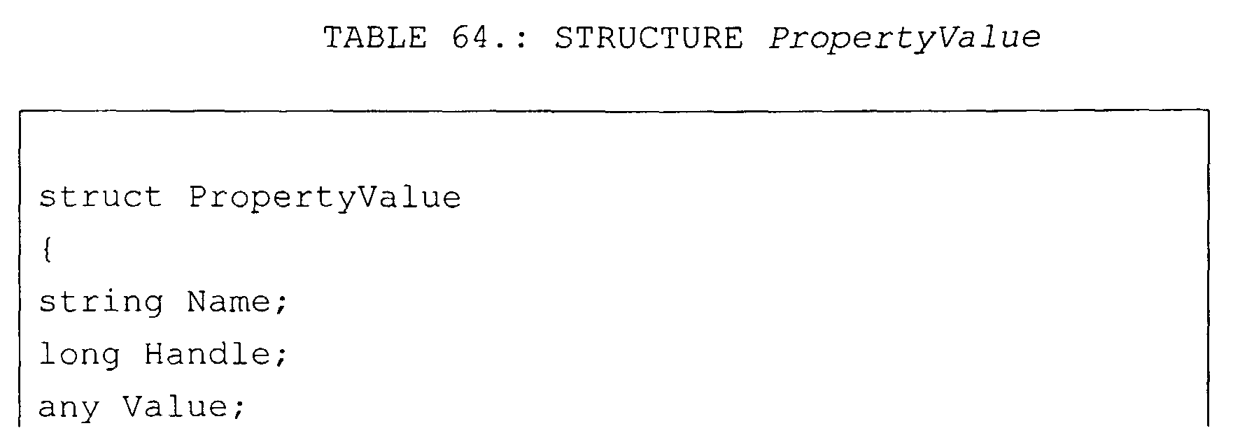

Structure Property describes a property of the content.
There are three types of properties: bound properties;
constrained properties; and free properties. Name
specifies the name of the property. The name is unique
within an XPropertySet. Handle contains an
implementation-specific handle for the property. The
handle may be -1 if the implementation has no handle.
Type contains an object that identifies the declared
type for the property. If the property has multiple
types or the type is not known but not any, void must
be returned. Field attributes may contain zero or more
constants of the PropertyAttribute constants group.
See constants PropertyAttribute above.

Exception UnknownPropertyException is thrown to
indicate that the property is unknown to the
implementation.

Interface XPropertiesChangeListener receives events,
which get fired whenever a bound property is changed.
Interface XPropertiesChangeListener inherits from
interface XEventListener. Method propertiesChange is
called when bound properties are changed. Input
parameter aEvent contains a sequence of Properties
Change Event objects that describe the event source and
the properties that have changed.

Structure PropertyChangeEvent is delivered whenever a
"bound" or "constrained" property is changed. A
PropertyChangeEvent object is sent as an argument to
the methods of interface XPropertyChangeListener.
Normally, such events contain the name and the old and
new value of the changed property. Void values may be
provided for the old and the new values if their true
values are not known.

As described above, a content object that creates
content implements interface XContentCreator. This
interface defines what type of content may be created
via method queryCreatableContentsInfo. This interface
returns a structure, which contains the MIME types of
content that may be created. New content is created by
calling method createNewContent with the appropriate
ContentInfo, i.e., a supported MIME type. This method
does not persist the content since what has been
created has not been initialized. Initialization may
result in property and command operations on the new
content. When the content has been initialized, the
content can be inserted into the parent. Figure 20 is
a sequence diagram that illustrates the asynchronous
operation of a command on a file system folder. In
this example folder adapter object 505 implements
interface XContentTaskEnvironment, and issues a call to
method createCommandTask of a folder object that
implements interface XCommandTaskProcessor.
In response to the call to method createCommandTask, a
call to method create (Fig. 20) in interface
XCommandTask of an opentask object is issued.
Interface XCommandTask issues a call to method
getClient of interface XContentTaskEnvironment. When
the task is returned to interface
XContentTaskEnvironment, an interface
XContentTaskClient is created for the task and then
method start is called in interface XCommandTask.
Notice that the method returns before execution is
completed.
At a later time, interface XCommandTask executes the
task by making systems calls to the operating system.
Also, the task status is returned to interface
XContentTaskClient. When the task is done, a done
event is sent to interface XContentTaskClient that
calls method commandready in interface
XContentTaskEnvironment to indicate that the task is
done. Notice that the folder adapter object was not
required to remain active while the task was being
executed.
The following table is another pseudo-code example of
the use of the interfaces described above. In this
example, UCB 113 is used to open a file folder and to
add a new file in the file folder. As described above,
a runtime function getGlobalServiceManager is used to
create an instance of UCB 113 that implements service
UniversalContentBroker. As shown in Figure 21, a file
system registers with UCB 113 as a universal content
provider 2131 for protocol "file" that was sometimes
referred to as a URL scheme. As illustrated in
Figure 21, universal content provider 2131 uses
interface XContentProviderManager, which was described
above, to register with UCB 113 and to be place in
provider registry 2101.
A client of UCB 113, which as described above can be an
application/service in remote applications 310, a
folder adapter 505 of Figure 5, or a JAVA bean of
Figure 8, creates an identifier factory that implements
interface XContentIdentifierFactory. The client
creates a provider object that implements interface
XContentProvider, and then obtains an identifier for a
folder on the file system by passing a URL to the
folder to method createContentIdentifer of interface
XContentIdentifierFactory. To open the file system
folder, the client, as illustrated in Figure 21 issues
a call to method queryContent to interface
XContentProvider of the provider object.
Next, to create a file as new UCB content, a content
creator object is defined that implements interface
XContentCreator. Method createNewContent is called in
the content creator object with content type of
text/html to create object newfileContent. Properties
of the new file are initialized, and then property task
processor is created that implements interface
XPropertyTaskProcessor. A property task is obtained by
a call to method createPropertyTask (See Fig. 21 and
following Table) and then executed to assign the
properties to object newfileContent. Next, the file
with the properties is inserted in the parent folder
using interface XCommandProcessor.


From the content object, a reference to interface
XIndexAccess is obtained. The number of children is
obtained from method getCount. Each child is obtained
via method getByIndex, which is of type Any. If type
Any can be cast to a reference to a pointer to
interface XContent, an XContent reference is obtained.
The XContentIdentifier reference is obtained from
interface XContent. From this the scheme is printed
out. From XContent the MIME type is printed out. See
the following table.


Once an XContent reference is obtained for a content
object, it is possible, if supported, to execute tasks
on the content to send commands or get and set values
of properties.
From the content object, a reference to interface
XCommandProcessor is obtained. If the reference is
valid, a reference to interface XCommandInfo is
obtained and from this the sequence of possible
commands. The command names are then printed out.
A reference to interface XCommandTask is created from
the reference to interface XCommandTaskProcessor with a
given Command and reference to the
XContentTaskEnvironment. If the task is valid, the
task is executed synchronously via method execute. The
resultant object of type any is obtained via method
getResult. See the above examples.
From the XContent reference the XPropertyTaskProcessor
reference is obtained. If the task is valid, then the
reference to interface XPropertySetInfo is obtained via
the method getPropertySetInfo. The sequence of
property names is then obtained from method
getProperties. The property names are then printed
out.
From the XPropertyTaskProcessor reference, an
XPropertyTask reference is created via the method
createPropertyTask with a sequence of properties and a
reference to interface XContentTaskEnvironment. If the
task is valid, the property is obtained by calling
method execute. Thus, the property is obtained
synchronously. The sequence of values is then obtained
from method getProperties method. The value of the
first property is then obtained in an any.
As described above, UCB 113 aggregates the content from
different transport protocols and different storage
systems in a homogeneous API. As the UCB aggregates
content on API level, hierarchy service 335 extend the
concept of hierarchal relations to virtual hierarchy of
UCB contents (Figure 2D). Hierarchy service 335 is a
UCP, which provides three kinds of contents: a root
folder, virtual folders and links to other UCB
contents. This means a client can use hierarchy
service 335 to store a user defined 'view' on several
UCB contents. The 'view' is defined by the
hierarchical relation between virtual folders and links
to other UCB contents. These relations are stored in
user configuration service, as described above.
Hierarchy service 335 provides three different types of
contents: a HCP Link, a HCP Folder and a HCP Root
Folder. A HCP link 2202A is a content, which points to
another UCB content 2203A. A HCP link 2202A is always
contained in a HCP Folder 2200. A HCP Link has no
children. A HCP Folder, e.g., folders 2200, 2201A
to 2201C, is a container for other HCP Folders and HCP
Links. There is at most one instance of a HCP Root
Folder 2200 at a time. All other HCP contents are
children of this folder. The HCP Root Folder can
contain HCP Folders and HCP Links. In one embodiment,
root folder 2200 has a URL such as vnd.sun.star.hier:/.
HCP Folders 2201A to 2201C and HCP Root Folder 2200
implement the interface XContentCreator. HCP Links and
HCP Folders support the command "insert". This means
all HCP Folders and the HCP Root Folder as well can
create new HCP Folders and HCP Links.
To create a new child of a HCP Folder, the parent
folder creates a new content by calling its method
createNewContent. The content type to use for new
folders is application/vnd.sun.star.hier-folder. To
create a new link, the type string
application/vnd.sun.star.hier-link is used. The URLs
used here are illustrative only and are not intended to
limit the invention to the specific example.
To set a title at the new folder/link, the new child
executes a command setPropertyValues, which sets at
least the property "Title" to a non-empty value. Also,
the child can set the property TargetURL as well at
this time, but this is not required. This property may
also be set later.
Next, the new child (not the parent ) executes the
command "insert". This commits the creation process.
Each HCP content has an identifier corresponding to the
following scheme:
vnd.sun.star.hier:/<path>
where <path> is a hierarchical path of the form
<name>/<name>/.../<name> where <name> is a string encoded according to the URL conventions.
vnd.sun.star.hier:/<path>
where <path> is a hierarchical path of the form
<name>/<name>/.../<name> where <name> is a string encoded according to the URL conventions.
vnd.sun.star.hier:/ ( The URL of the HCP Root Folder ) vnd.sun.star.hier:/Bookmarks/Sun%20Microssystems%20Home
% 20 Page
vnd.sun.star.hier:/Workplace/Printers
vnd.sun.star.hier:/Workplace/Printers
The following table gives an overview of different HCP
contents.
| UCB Type | Properties | Commands | Interfaces | |
| (returned | ||||
| by | ||||
| XContent:: | ||||
| getContent | ||||
| Type ) | ||||
| Link | applicatio | ContentType | getCommandsInfo | XTypeProvider, |
| n/vnd.sun. | IsDocument | getPropertySetInfo | XServiceInfo, | |
| star.hier- | IsFolder | getPropertyValues | XComponent, | |
| link | Title | setPropertyValues | XContent, | |
| TargetURL | insert | XCommandProcessor, | ||
| delete | XPropertiesChangeNo | |||
| tifier, | ||||
| XPropertyContainer, | ||||
| XPropertySetInfoCha | ||||
| ngeNotifier, | ||||
| XCommandInfoChangeN | ||||
| otifier, XChild | ||||
| Folder | applicatio | ContentType | getCommandInfo | same as HCP Link, |
| n/vnd.sun. | IsDocument | getPropertySetInfo | XContentCreator | |
| star.hier- | IsFolder | getPropertyValues | ||
| folder | Title | setPropertyValues | ||
| insert | ||||
| delete | ||||
| open | ||||
| transfer | ||||
| Root | applicatio | ContentType | getCommandInfo | same as HCP Link, |
| Folde | n/vnd.sun. | IsDocument | getPropertySetInfo | XContentCreator |
| r | star.hier- | IsFolder | getPropertyValues | |
| UCB Type | Properties | Commands | Interfaces | |
| (returned | ||||
| by | ||||
| XContent:: | ||||
| getContent | ||||
| Type ) | ||||
| folder | Title | setPropertyValues | ||
| open | ||||
| transfer* |
HCP 335 is transparent for the client program code,
whether the UCB content is stored on the file system,
retrieved via HTTP or just a virtual folder, provided
by the users configuration. Transparent means, that
the same client program code, which works on a UCB
content from file system, works on UCB content from HCP
and any other UCP, too. HCP 335 uses configuration
server 336 as persistent storage for the virtual
hierarchy. In one embodiment, the hierarch content
provider 335 stores the relations between virtual
folders and links also in XML.
Interface XPropertiesChangeNotifier includes two
methods. Method addProperkiesChangeListener adds an
interface XPropertiesChangeListener to the specified
properties with the specified names. Input parameter
PropertyNames specifies the names of the properties.
An empty sequence means "all properties". Input
parameter Listener contains the listener for the
property change events. Method
removePropertiesChangeListener removes an interface
XPropertiesChangeListener from the list.

Interface XPropertyContainer includes methods to add a
property and remove a property from a container.
Parameter Name specifies the name of the new property.
Parameter Attributes specifies the attributes for the
new property. Parameter DefaultValue specifies the
default value for the new property.


Interface XPropertySetInfoChangeNotifier includes
methods to add and remove listeners for property set
information change events.

Interface XPropertySetInfoChangeListener includes
method propertySetInfoChange that is called whenever
changes of an interface XPropertySetInfo is to be
propagated.


Interface XCommandInfoChangeNotifier adds, i.e.,
registers listeners for CommandInfoChangeEvents.

The function of interface XCommandInfoChangeListener is
equivalent to the other listener interfaces described
above.

Other interfaces that are used include the following.
Interface XIdlClass provides information about a type
or module. Every array also belongs to a type that is
reflected as a XIdlClass object that is shared by all
arrays with the same element type and number of
dimensions. Finally, any of the primitive IDL types
are also represented as XIdlClass objects. This
includes "void, any, boolean, char, float, double,
octet, short, long, hyper, unsigned octet, unsigned
short, unsigned long" and "unsigned hyper". Interface
XIdlClass inherits from interface XInterface.

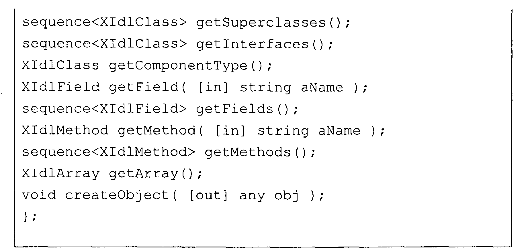
Method getClasses returns all types and modules, which
are declared in this class. Method getClass returns a
type or module with the given name that is declared in
this class. Method equals returns <TRUE> if the
instances describe the same type, otherwise <FALSE>.
Method isAssignableFrom tests if the parameter xType is
a subclass of this class. Method getTypeClass returns
the type that this instance represents. Method getName
returns the fully qualified name of the type of object
(class, interface, array, sequence, struct, union, enum
or primitive) represented by this XIdlClass object.
Method getUik returns the UIK from this type. If the
type has no UIK, the returned UIK is zero.
If this object represents an interface or a class, the
objects that represent the superclasses or
superinterfaces of that class are returned by method
getSuperclasses. If this object is the one that
represents the topmost class or interface, an empty
sequence is returned.
Method getInterfaces determines the interfaces
implemented by the class or interface represented by
this object. If the class or interface implements no
interfaces, the method returns a sequence of length 0.
If this class represents an array or sequence type,
method GetComponentType returns the XIdlClass object
representing the component type of the array or
sequence; otherwise it returns null. Method getField
returns a XIdlField object that reflects the specified
member field of the class, interface, struct, union,
enum or exception represented by this XIdlClass object.
If a field with the specified name is not found, zero
is returned. The field to be reflected is located by
searching all the member fields of the class,
interface, struct, union, enum or exception represented
by this XIdlClass object for a field with the specified
name or for NULL, if a field with the specified name is
not found. Parameter aName specifies the simple name
of the desired field.
Method getFields returns a sequence containing Field
objects reflecting all the accessible fields of the
class, interface, struct, union or enum represented by
this XIdlClass object. Method getFields returns a
sequence of length zero if the class or interface has
no accessible fields, or if it represents an array, a
sequence or a primitive type. Specifically, if this
XIdlClass object represents a class, this method
returns the fields of this class and of all its
superclasses. If this XIdlClass object represents an
interface, the method returns the fields of this
interface and of all its superinterfaces. If this
XIdlClass object represents an array, sequence or
primitive type, this method returns a sequence of
length zero.
Method getMethod returns a XIdlMethod object that
reflects the specified member method of the interface
represented by this XIdlClass object. If a method with
the specified name is not found, "0" is returned. The
method to be reflected is located by searching all the
member methods of the interface represented by this
XIdlClass object for a method with the specified name.
Parameter aName specifies the simple name of the
desired method.
Method getMethods returns a sequence containing
XIdlMethod objects reflecting all the member methods of
the class or interface represented by this XIdlClass
object, including those declared by the class or
interface and those inherited from superclasses and
superinterfaces. Returns a sequence of length 0 if the
class or interface has no member methods.
Method getArray returns interface XIdlArray to get and
set the elements by index if the represented type is an
array or sequence. Method createobject creates an
instance of the type represented by this XIdlClass
object if the represented type is a basic type, struct,
enum, or sequence.
Enumeration TypeClass describe all type classes, which
can be defined in the IDL.


Interface XIdlField inherits from interface XIdlMember.
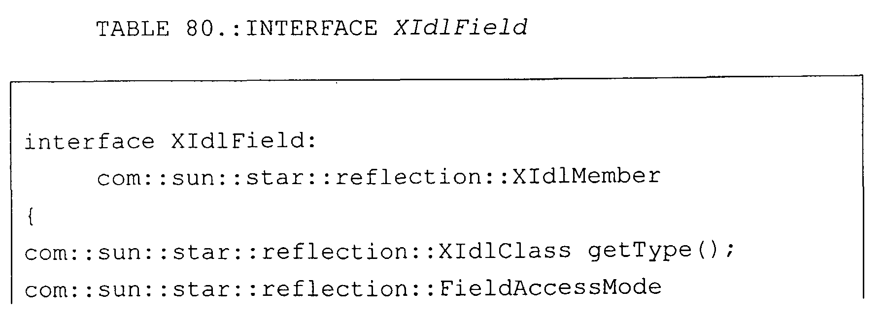

Method getType returns a XIdlClass object that
identifies the declared type for the field represented
by this XIdlField object. Method getAccessMode returns
an enumeration value, which denotes whether the field
is "const", "readonly", "writeonly" or "readwrite".
Method get returns the value of the field represented
by this field on the specified object. The underlying
field's value is obtained as follows:
If the underlying field is a constant, the object argument is ignored; it may be NULL;
If the underlying field is a constant, the object argument is ignored; it may be NULL;
Otherwise, the underlying field is an instance
field.
If the specified object argument is NULL, the method
throws an "IllegalArgumentException". If the specified
object is not an instance of the class, interface,
struct, union or enum declaring the underlying field,
the method throws an "IllegalArgumentException".
Otherwise, the value is retrieved from the underlying
instance or constant.
Method set sets the field represented by this XIdlField
object on the specified object argument to the
specified new value. The operation proceeds as
follows. If the specified object argument is NULL, the
method throws an exception IllegalArgumentException.
If the specified object argument is not an instance of
the class or interface declaring the underlying field,
the method throws an exception
IllegalArgumentException. If the underlying field is
constant, the method throws an exception
IllegalAccessException. If the new value cannot be
converted to the type of underlying field by an
identity or widening conversion, the method throws an
IllegalArgumentException. The field is set to the
possibly widened new value.
Interface XIdlMember inherits from interface
XInterface. Interface XIdlMember makes it possible to
access members of classes dynamically.

Method getDeclaringClass returns the XIdlClass object
representing the class, interface, struct, union or
enum that declares the member represented by this
member. Method getName returns the fully qualified
name of the type (class, interface, array, sequence,
struct, union, enum or primitive) represented by this
XIdlClass object, as a string.
The values in enumeration FieldAccessMode are used to
specify the kind of attribute or property.

Exception IllegalArgumentException is thrown to
indicate that a method has passed an illegal or
inappropriate argument. Exception
IllegalArgumentException inherits from exception
Exception. Field ArgumentPosition identifies the
position of the illegal argument. This field is -1 if
the position is not known.

Exception IllegalAccessException is thrown when an
application tries to change a constant property.
Exception IllegalAccessException inherits from
exception Exception.

Interface XIdlMethod inherits from interface
XIdlMember. Interface XIdlMember makes it possible to
access the specification of a method dynamically.


Method getReturnType returns a XIdlClass object that
represents the formal return type of the method
represented by this method object. Method
getParameterTypes returns a sequence of XIdlClass
objects that represent the formal parameter types, in
declaration order, of the method represented by this
Method object. Method getParameterTypes returns a
sequence of length 0 if the underlying method takes no
parameters.
Method getParameterInfos returns a sequence of
ParamInfo objects that represent all information about
the formal parameter types, in declaration order, of
the method represented by this Method object. Method
getParameterInfos returns a sequence of length 0 if the
underlying method takes no parameters.
Method getExceptionTypes returns a sequence of
XIdlClass objects that represent the types of the
checked exceptions thrown by the underlying method
represented by this Method object. Method
getExceptionTypes returns a sequence of length 0 if the
method throws no checked exceptions.
Method getMode returns an enumeration value, which
denotes whether the method is one-way or two-way.
Method invoke invokes the underlying method represented
by this method object on the specified object with the
specified parameters. Individual parameters are
subject to widening conversions as necessary.
Method invocation proceeds in the following order:
If the number of actual parameters supplied via args is
different from the number of formal parameters required
by the underlying method, the invocation throws an
Exception IllegalArgumentException. For each actual
parameter in the supplied args array, if the parameter
value cannot be converted to the corresponding formal
parameter type by an identity or widening conversion,
the invocation throws exception
IllegalArgumentException. When the control transfers
to the underlying method and the method stops abruptly
by throwing an exception, the exception is placed in an
exception InvocationTargetException and thrown in turn
to the caller of the method. If the method completes
normally, the value it returns is returned to the
caller of the method. If the underlying method returns
type is void, the invocation returns VOID.
Structure ParamInfo describes a formal parameter of a
method.

The values in Enumeration ParamMode are used to specify
if a formal parameter of a method is used for input,
output or both. If the value is an IN parameter, data
can only transferred from the callee to the caller. If
the value is an OUT parameter, data can only
transferred from the caller to the callee. If value is
an INOUT parameter, data can be transferred in both
directions.

The values in Enumeration MethodMode are used to
specify the calling mode of a method. If the value is
an ONEWAY parameter, the method call may be
asynchronous. If the value is a TWOWAY parameter, the
method call is synchronous.

Exception InvocationTargetException is a checked
exception that wraps another exception. Typically such
exceptions are thrown by an invoked method or
constructor. Exception InvocationTargetException
inherits from exception WrappedTargetException.

Exception WrappedTargetException is a checked exception
that wraps an exception thrown by the original target.
Normally this exception is declared for generic
methods. Exception WrappedTargetException inherits
from exception Exception.

Interface XIdlArray provides methods to dynamically
access arrays. Interface XIdlArray inherits from
interface XInterface.

Method realloc in interface XIdlArray changes the size
of the array to the new size. If the new length is
greater, the additional elements are default
constructed, otherwise the elements are destructed.
Method realloc throws an exception
IllegalArgumentException if the specified object is not
an array or if the specified object is null.
Method getLen in interface XIdlArray returns the number
of elements in the array. Method getLen throws an
exception IllegalArgumentException if the specified
object is not an array or if the specified object is
null.
Method get in interface XIdlArray returns the value of
the indexed component in the specified array object.
Method get throws exception IllegalArgumentException,
if the specified object is not an array or if the
specified object is null. Method get throws exception
ArrayIndexOutOfBoundsException, if the specified index
argument is negative, or if the specified index
argument is greater than or equal to the length of the
specified array.
Method set in interface XIdlArray sets the value of the
indexed component of the specified array object to the
specified new value. Method set throws exception
IllegalArgumentException, if the specified object is
not an array or if the specified object is null.
Method set throws exception ArrayIndexOutOfBoundsException, if the specified index argument is negative, or if the specified index argument is greater than or equal to the length of the specified array.
Method set throws exception ArrayIndexOutOfBoundsException, if the specified index argument is negative, or if the specified index argument is greater than or equal to the length of the specified array.
Exception ArrayIndexOutOfBoundsException is thrown to
indicate that an array has been accessed with an
illegal index. The index is either negative or greater
than or equal to the size of the array. Exception
ArrayIndexOutOfBoundsException inherits from exception
IndexOutOfBoundsException.

Exception IndexOutOfBoundsException is thrown to
indicate that a container has been accessed with an
illegal index. The index is either negative or greater
than or equal to the count of the elements. Exception
IndexOutOfBoundsException inherits from exception
Exception.

Those skilled in the art will readily understand that
the operations and actions described herein represent
actions performed by a CPU of a computer in accordance
with computer instructions provided by a computer
program. Therefore, the various processes described
herein, and the interfaces described herein may be
implemented by a computer program causing the CPU of
the computer to carry out instructions representing the
individual operations or actions as described
hereinbefore. The computer instructions can also be
stored on a computer-readable medium, or they can be
embodied in any computer-readable medium such as any
communications link, like a transmission link to a LAN,
a link to the internet, or the like.
Thus, the processes and/or interfaces can be
implemented by a computer program comprising computer
program code or application code. This application
code or computer program code may be embodied in any
form of a computer program product. A computer program
product comprises a medium configured to store or
transport this computer-readable code, or in which this
computer-readable code may be embedded. Some examples
of computer program products are CD-ROM discs, ROM
cards, floppy discs, magnetic tapes, computer hard
drives, servers on a network, and carrier waves. The
computer program product may also comprise signals,
which do not use carrier waves, such as digital signals
transmitted over a network (including the Internet)
without the use of a carrier wave.
Herein, a computer memory refers to a volatile memory,
a non-volatile memory, or a combination of the two in
any one of these devices. Similarly, a computer input
unit and a display unit refer to the features providing
the required functionality to input the information
described herein, and to display the information
described herein, respectively, in any one of the
aforementioned or equivalent devices.
In the following, further embodiments of the invention
will be described with respect to Figs. 23 - 33.
Referring to Fig. 23, the network portal system 2310
according to the invention is illustrated to be placed
between provider systems 2301A, 2301B and client
systems 2302A, 2302B in a network 2303. Between the
network portal system 2310 and the clients 2302A, 2302B
placed is a network server 2312 which in turn is
connected to the network 2303. If the network 2303 is
the internet, the network server 2312 may be an HTTP
server. The network server 2312 is adapted for
performing communication with any client system 2302A,
2302B via the network 2303, for ex., receiving requests
for content from client systems and transmitting
responses produced within the network portal system
2310 to the respective client systems 2302A , 2302B.
Client system 2302A is illustrated to be a computer,
and is supposed to execute an internet browser program.
Client system 2302B is illustrated to be a mobile
telephone which is linked to a mobile telephone network
2304 which has a gateway 2343 to the network 2303. The
provider systems 2301A, 2301B are adapted to offer
content such as data bases, file systems, for access or
use for client systems 2302A, 2302B. Provider systems
providing arbitrary other content may be linked to the
network, too. It is to be noted that the communication
connections mentioned here may be of permanent or
temporary nature. They may be physically direct or
indirect.
A portal may be an interface system which is placed
between provider systems and client systems in a
network, for enabling communication between the
provider systems and the client systems. Provider
systems may be computer systems which provide content
or services via a network to client systems. The client
systems represent the user of the content or services.
In this context, the term "content" may denote any
information, which may be of any kind, and comprised in
any physical or logical format which is suitable to be
transmitted over a communication network. In
particular, content may be of the form of electronic
files, residing on a server, or it may be generated by
a particular program application.
The term "service" may comprise in particular
communication based services (e.g.: e-mail, ftp
transmission) as well as rendering functionality like
word-processing or drawing capabilities, or rendering
information content (e.g., documents).
The great number of different content and services
available over a network like the internet have lead to
an enormous variety of different communication
standards, data formats and file formats, which are
sometimes proprietary for the particular content and
services. Communication standards, i.e., protocols
which define the way of communication of between two
systems, and the MIME type which defines the type of
content, are here referred to as communication schemes.
In general, the communication scheme supported by a
system is contained in the system's identifier in the
network, or in the identifier of the particular service
or content provided by the system. As identifier for
systems, services or content, the Uniform Resource
Locator (URL) is used. A URL always starts with a
communication scheme which is to be used for accessing
the appropriate provider system. An example may be:
"imap://user@mailserver/inbox". The communication
scheme is here the IMAP protocol. This URL specifies a
message which is located in a folder "inbox" of a
provider system "mailserver ".
As a consequence, services or content provided by some
provider systems may be incompatible with services or
content provided by other provider systems and thus
have a "stove-pipe" nature as to their presence and
operation on networks. In addition, there exist many
different communication schemes for content or service,
which communication schemes again may be incompatible
and not universally accessible or supported by all
client systems.
The inventive network portal system 2310 according to
the embodiment illustrated in Fig. 24 is divided into
several subsystems. One of them are the means 2411
which are adapted to deliver content in a communication
scheme as required by the particular client systems
2302A, 2302B. The means 2411 are referred to as a
webtop.
Another subsystem of the network portal system 2310 is
constituted by the means 2413 which interact with the
provider systems 2301A, 2301B for accessing and
retrieving content. These means 2413 are referred to as
universal content broker (UCB) 2413.
The webtop 2411 is a software implementation to provide
a metaphor to client systems for accessing content. The
webtop 2411 comprises a user interface which is defined
in different XML, HTML or WML templates in order to be
able to present content in the form as required by any
individual client system. These templates define
together with the stylesheets and the rendering process
the visual look and feel of the network portal system
2310. Hereby, the templates define elements of the
content to be presented. Examples of such elements are
text, tables, images, file names. The stylesheets
define the form how the elements are to be presented on
an individual client system. As an example, a
stylesheet may define the layout of the elements on a
page to be displayed on the a screen. To deliver
content to a client system via this rendering process,
the content has to become a part of the template. On
the other hand, the content is not static and will
change over time, and also the templates are
independent from the client system.
Depending on the capabilities of a particular client
system which communicates with the webtop 2411, one of
these templates is selected for interaction with the
particular client system. The webtop 2411 loads the
template, fills in all user specific content data, and
this new temporary template is processed by a
stylesheet and transmitted to the client system.
For example, if the user is accessing his email via a
browser, the template will be an HTML file. The webtop
2411 uses UCB 2413 to get the content of the mails and
insert the data as an HTML table in the HTML template.
This template includes the user specific mail data, and
is then processed through the stylesheets and
transmitted to the client system.
The webtop 2411 may be implemented in Java as different
servlets, so it can easily communicate with different
kinds of network servers 2312. The webtop 2411 is using
a special template core engine, which is able to insert
dynamic data into the templates and renders these
templates according to different stylesheets. With
these stylesheets, the webtop 2411 can be adapted to
special client systems or user purposes. It comprises
for example the logic for presenting e-mail content in
a kind of folder view to a client system.
As concept for offering content to a variety of
different client system, the framework of individual
data representation according to Annex II may be
applied. By definition of dynamic content channel
"portlets", highly customizable content pages may be
produced for any individual client system. Every
portlet defines in which format the content can be
provided. The client can subscribe to any of the
available portlets. The framework and all portlets are
implemented as servlets running on the webtop 2411.
With respect to client systems, the webtop 2411 may
perform login procedures. Furthermore, authentication
procedures for client systems may be required for
requesting particular content from the network portal
system 2310.
The UCB 2413 interacts with the provider systems for
retrieving the content requested by a client system.
The access is performed on the basis of the request
transmitted by the client system to the network portal
system 2310. The request specifies the service, and
comprises an indicator specifying the client system and
the communication scheme to be applied for
communicating with the client system.
As an example, the UCB 2413 may provide an hierarchical
view to all content, which is provided by a provider
system, regardless of the content type. A unified
navigation through all content can be may be enabled
for all kinds of client systems. The standard
information exchange services like e-mail, news,
calendar, directory, databases, internet communication,
web content and file storage are supported by the UCB
2413, and for the integration of additional content or
applications, interfaces for the integration of content
providers are supported by the UCB 2413. For example,
on top of the UCB 2413, an application is able to
navigate through the e-mails of an client like
navigating through a calendar server. The hierarchical
view to all this information can be configured
dynamically.
The provider systems 2301A, 2301B which may be accessed
by the UCB 2413 for retrieving content are contained in
a provider register 2415 in association with the
communication scheme they support. The UCB 2413 has
access to that provider register. Optionally, the UCB
2413 is maintaining the provider register 2415, i.e.,
registering provider systems, or de-registering
provider systems.
In a further embodiment of the network portal system
2310, the UCB 2413 is adapted to store content in a
local storage 2416. The content is stored in
association with the URL of the content. This feature
permits using or processing the content without being
permanently connected to the provider system where the
content has been retrieved from.
The interface used in the UCB 2413 for storing content
allows the usage of different implementations. For a
small network portal system 2310, the functionality of
this implementation may be an ordinary file. To provide
scalability of the network portal system 2310, a
database can be used with an adapter providing the
implementation of the interface. This opens a
functionality not just using the UCB 2413 to access
this content, but also other application software may
working together with the database to access the stored
content.
For increasing the availability of a network portal
system, the replication features of a database system
may be used for maintaining an identical copy of the
database on a second computer system. Then, if the
first computer fails by a hardware or software failure,
the second computer system can provide the same
functionality like the first one.
In a further embodiment, the UCB 2413 is adapted to
associate properties to content which is retrieved from
a content provider system. These properties may contain
additional information with respect to the content. The
properties are set or changed by the UCB 2413. The
properties or attributes are transmitted along with the
retrieved content to the respective client system. The
properties along with the association with the content
(referenced by its URL) are stored in a storage which
is accessible by the UCB 2413. Whenever a request for
the content is received by the UCB, the storage is
looked up for its associated properties on the basis of
its URL. The properties may then be transmitted along
with the content to the client system.
The retrieval of content by the UCB 2413 is explained
with reference to Figures 25 to 27.
Fig. 25 illustrates the retrieval of content
constituting a message on an IMAP server with an
associated property. An example for such an URL may be:
imap://user@mailserver/inbox;UID=3. Accordingly, the
content has an associated property value UID set to 3.
In the first step 2501, the URL is passed from the
webtop 2411 to the UCB 2413. In step 2502, the UCB 2413
searches the appropriate provider system for the IMAP
communication scheme based on the provider register to
which the UCB has access. Then, in step 2503, the UCB
connects to the appropriate provider system and
transmits the URL to it. In step 2504, the provider
system analyzes the URL and creates an IMAP message
content. In step 2505, the IMAP message content is
transmitted back to the UCB 2413. In step 2506, the UCB
2413 passes the received content to the webtop 2411,
which in turn fits it into the template and forwards it
to the client system (step 2507).
Fig. 26 illustrates an example of setting a property
value which is associated with a message of an IMAP
server. Upon request by a client system, the UCB 2413
performs a step 2310 for retrieving content as
specified by the URL of the IMAP message. Then, in step
2620, the value of the content property "IsRead" is set
to "true". In step 2630, the UCB 2413 connects to the
IMAP server and instructs the IMAP server to mark the
message as read. In step 2640, the message data in a
cache storage in USB 2413 is updated.
A property may also be retrieved from a message on an
IMAP server. Fig. 27 illustrates an example of
retrieving a property value. First, the UCB checks
whether the message data is stored in a local cache of
the network portal system 2310 (step 2750). If so, the
property value is retrieved from the local cache (step
2760A). Otherwise, the UCB 2413 connects to the IMAP
server and downloads the message (step 2760B). The
downloaded message is then stored in the local cache
(step 2770B). In both cases, the property value is read
and returned to the client system (step 2780).
The UCB 2413 may be further adapted to automatically
notify individual client systems whenever new content
is created by the UCB 2413. To this end, the
functionality of creating new content is associated
with the individual client systems ("listeners"). When
the UCB 2413 creates new content, the UCB 2413 notifies
the individual listeners.
Further, the UCB may be adapted to automatically notify
individual client systems whenever particular content
is processed by the UCB 2413. For this functionality,
the UCB 2413 maintains a register where the URL of the
content is associated with the URL of the individual
client systems to be notified are registered. Then,
whenever content is processed, it is verified whether
there is an association of that content with listeners.
If so, the associated listeners are notified.
The notification may be dependent upon the kind of
content processing. Some listeners may be informed
whenever content is changed, some listeners may be
informed when content is deleted.
The notification mechanism may be used for
synchronizing several client systems, i.e., for
updating content changes initiated by one client
systems to other client systems.
The generic application programming interface (API) for
a content provider system can be extended by additional
content or services because the UCB 2413 is based on a
component technology which is able to support dynamic
interfaces. This allows a system architect not only to
use the UCB 2413 as a kind of central access system to
all content or services, nor it is only a kind of
navigation system for users to go through the available
content, it provides moreover an infrastructure for
building large enterprise applications, where the
ability for acting with different content and the
exchange of content is required. The uniform access
guarantees that the whole system can be adapted to
different infrastructures, without interfering the
different applications on top of the UCB 2413.
Depending on the capabilities of a client system, the
network portal system 2310 can not only provide the
information to a user for viewing content. If a client
system 2302A, 2302B is able to execute Java
applications, particular Java components 2414A, 2414B
can be used in the templates which deploy the
functionality of a word-processor or spreadsheet to the
client system 2302A, 2302B. Using a standard Java
enabled internet browser, a user may be able to write
or only change very complex documents on any client
system 2302A, 2302B running just a browser which has a
network connection to the network portal system 2310.
Another solution is to dynamically transcode from one
file format to another while transmitting the content.
For a native running application on, for example, a
palm system this enables the ability to modify a
document using this client system. Later, the
modifications made on the palm system documents can be
transmitted back to the network portal system 2310 and
can be applied to the document in the original format.
For client systems 2302A, 2302B which are not
permanently connected to the network 2303, the network
portal system 2310 provides the ability to synchronize
the content of the two UCB via a synchronization
component 2414C. A user can read and change his
documents while being off-line and after he is going
online he can synchronize all this changes with the
network portal system 2310.
Optionally, the webtop servlet is accessing this
information by using the network portal system API.
This is a language independent API for accessing all
the functionality of a predetermined Office program
bundle comprising word-processing, drawing,
calculating, tabulating, file displaying capabilities.
Then, the same UCB 2413 can be used by the Office
program bundle and also by the network portal system,
so a client can use the Office program bundle while
working in his office and on the other hand he can use
the network portal system to access all his files and
information via the network portal system when he is
not in his office.
Next, by referring to Fig. 28, the inventive method for
linking a plurality of provider systems with a
plurality of client systems via the network portal
system 2310 is explained. In step 2810, a content
request is received from a client system (2302A,
2302B), said request comprising a content indicator
being indicative of the content, and an indicator of
the requesting client system (2302A, 2302B), said
client system indicator specifying the communication
scheme supported by said client system (2302A, 2302B).
Then, in step 2820, a provider system (2301A, 2301B) is
searched which is able to provide said requested
content. In step 2830, said selected provider system
(2301A, 2301B) is accessed. In step 2840, said
requested content is retrieved from said accessed
provider system (2301A, 2301B). Finally, in step 2850,
the retrieved content is rendered to said requesting
client system (2302A, 2302B) according to the
communication scheme of said requesting client system
(2302A, 2302B).
Next, by referring to Figs. 29 and 30, the method for
providing content to a client system is explained. The
client system requesting content is a mobile telephone
2302B.
First, in step 2901, the HTTP server 2312 receives a
request sent from the mobile telephone 2302B. The
request comprises the requested content as well as the
URL of the mobile telephone 2302B. The request is
passed by the HTTP server 2312 to the webtop 2411 of
the network portal system 2310 (step 2902).
In the step 2903, a login procedure for the mobile
phone 2302B onto the webtop 2411 is started. If the
login fails, the webtop 2411 initiates an
administration procedure 2916 in which an ID and a
password for client system 2302B is defined. The
administration procedure 2916 will be described later.
On the other hand, if the login in step 2903 is
successful, an authentication procedure 2904 is started
in which the identity as well as accessing rights of
the mobile telephone 2302B are verified. If the
authentication fails, the client administration
procedure 2916 is initiated.
If the authentication in step 2904 is successful, the
webtop 2411 selects the template as specified by the
received URL (step 2905).
The content request is passed from the webtop 2411 to
the UCB 2413 (step 2906), which in turn accesses the
provider register and selects therefrom the appropriate
service provider system 2301A, 2301B for retrieving the
content (step 2907).
The content is then delivered by the selected provider
system 2301A, 2301B to the UCB 2413 (step 2908). The
UCB 2413 passes the received content to the webtop 2411
as it is (step 2909). Then, in step 2910, the webtop
2411 checks whether or not the communication schemes of
the provider system and client system match. If not so,
the webtop 2411 invokes a conversion procedure (step
3011) is in which an appropriate conversion component
2418A, 2418B for converting the content of the
provider's scheme into a representation according to
the client's scheme is executed. The conversion
procedure will be described later in connection with
Fig. 33.
Then the webtop 2411 fits the converted information
into the selected template (step 3012). Then, a
stylesheet according to the MIME type of the client
system 2302B is selected (step 3013). The template is
rendered according to the selected stylesheet (step
3014), forwarded via the HTTP server 2312 to the client
mobile phone 2302B having requested the content (step
3015).
On the other hand, if the communication scheme of the
selected provider 2301A, 2301B corresponds to the
communication scheme of the client 2302B, step 3011 is
stepped over, and the retrieved information can be fit
directly without further change into the template,
rendered according to the selected stylesheet and
forwarded via the HTTP server 2312 to the client system
2302B.
Next, referring to Fig. 31, the administration
procedure 2916 an administration procedure in which an
ID and a password for a client system is described in
greater detail. In step 3101, the webtop 2411 selects a
stylesheet according to the communication scheme of the
client system. In step 3102, a login template
according to the communication scheme of the client is
rendered. A number of login templates, each being
specific for a certain MIME type, are available to the
webtop 2411. In step 3103, the selected login template
is transmitted, via the HTTP server 2312, to the client
system requesting the login. Upon receiving the login
template, the client system can initiate the login
procedure (step 3104). This login procedure comprises
defining a login and a password for the client system
(step 3105).
Referring now to Fig. 32, a case is described where the
client system is a computer 2302A executing a browser
program, which accesses the network portal system 2310
for requesting content to be displayed within the
browser. For displaying the content, the service of a
specific drawing component 2414A is assumed to be
necessary. This component 2414A is hosted in the
network portal system 2310 together with other service
components 2414B, 2414C. For using the services of said
components 2414A, 2414B, 2414C, specific applets are
provided by the network portal system 2310. These
applets have to be transmitted from the network portal
system 2310 to the client computer 2302A prior to the
content.
The login procedure for computer 2302A is basically the
same as described above in connection with Fig. 31 and
is omitted here.
From the browser program being executed on computer
2302A a request to the HTTP server 2312 is sent for
retrieving the content (step 3202). The request is
passed to the network portal system 2310 (step 3201).
The webtop 2411 selects the template and the specific
applet for using the drawing service of component 2414A
(step 3202). The content identifier URL is entered into
the template (step 3203). The webtop selects as
stylesheet according to the MIME type "HTML" (step
3204), and renders the template accordingly. The
applet, embedded into an HTML page according to the
selected template, is transmitted to the computer 2302A
(step 3205).
Now, the procedure for providing the requested content
is started. First, the specific applet being executed
on client computer 2302A connects to the webtop 2411
(step 3206). The related service component 2414A is
called in order to load the content as specified by the
URL (step 3207). The content is requested from the UCB
2413 (step 3208). The UCB 2413 in turn accesses the
content according to the URL and passes it to the
service component 2414A (step 3209). The service
component 2414A, upon call by the related applet on the
client computer 2302A, renders the service necessary
for drawing the content information in the browser upon
transmitting it to the client computer 2302A (step
3210).
Referring to Fig. 33, the conversion of content is
described. Conversion is invoked whenever content
according to one communication scheme is to be
transcoded into content according to another
communication scheme.
First, it is checked whether the webtop 2411 can
process the content (step 3301). If not so, an error
message is issued to the client system (step 3302). On
the other hand, if the webtop 2411 can process the
content, it is then checked (step 3303) whether the
content is to be edited on the client system or only to
be displayed there. If the content is only to be
displayed on the client system, the best matching
communication scheme supported by the client system is
selected as scheme of conversion (step 3304). Then, the
corresponding conversion component 2418A is executed in
order to convert the content (step 3305), and the
converted document is then ready for being transmitted
to the client system as described above.
On the other hand, if the content is to be edited by
using webtop functionality, it is checked whether the
client system is able to execute the corresponding Java
applets which invoke the editing functionality (step
3306). If so, the webtop 2411 generates a template for
a HTML page with an applet embedded therein and sends
it to the client system (step 3307). The conversion of
the content is performed on the fly when transmitting
it to the client system (step 3308).
However, if the client system is not able to execute
Java applets, steps 3304 and 3305 are performed as
described above.
If content is represented in XML format, this offers
the potential for the synchronization of content
between various content provider systems that implement
the same content schema but obtain or store content
differently. The synchronization process them becomes a
comparison of time stamps and / or the comparison of
the XML content, which are both functions independent
of the content provider systems. Thus there can be
network portal content providers that are implemented
for various personal digital assistants (PDAs) which
can send and receive XML documents conforming to schema
for document areas as such as addressing, calendar and
scheduling, and mail.
Special purposes may be applications designed for being
executed on particular platforms like handheld
computers or mobile telephones, where storage and
processing capabilities are particularly limited.
Nevertheless, the whole functionality of the framework
is still accessible.
The synchronizing of content may also be extended to
area of multi-user operation when numerous people may
be operating on various areas of the content.
The network portal system offers not only a powerful
way of treating heterogeneous content in a homogeneous
manner but a way to group heterogeneous content
together with network information about content. In a
further embodiment of the invention, a network is
created which stores URLs that are organized according
to the defining semantics or hierarchy of another
client rather than the semantics or hierarchy that the
content prescribes. This also includes the structure of
the content. Network content is not defined by the
structure of the content and its children. Thus content
may be related to each other in an a-cyclical manner
rather than in the direct manner that file systems are
represented. In addition it is possible to inherit
network content structure and augment or modify it
without modifying the original.
An example is a network portal system specially used
for management of projects on which different teams are
working. For the automobile manufactures most often a
team of engineers, marketing specialists and finance
experts are working together. One team mostly need some
information from the other and also provides
information to the other. The only difference is which
data is important is important for one team and how
these should be organized in the best way for them. For
example the engineering team will produce CAD-drawing
and detailed lists of item needed to build a peace of
an automobile of the project. On the other hand the
finance experts are not interested in the CAD-drawing
and also not on the detailed list of items. They are
more interested in overall summary which items are need
to build the special peace, so they can calculate the
price for this and overall calculate the price for the
car. The marketing team may be interested in the
drawings, because give some feedback if the colors will
be accepted by the customers. So every is working on
the same project and also on the data files, but the
focus which data is used can be completely different.
The network portal system provides this infrastructure
by the capability of the UCB to browse through all
content and information using the UCB. Adding user
specific or task specific properties to a content,
enables the sorting or the creation of an hierarchical
view to this information, which can be completely
different to the physical structure on the disk.
It is also possible to build a similar system using the
Java 2 Enterprise Edition as a base system and at the
logic and management functionality on top of this in
form of Java application or Java beans. Also the whole
UCB system can be realized on top of a database, for
example an object oriented database or a XML-database.
Referring to the Annex I, an overview of the framework
for implementing the network portal system is presented
as defined in the interface definition language files.
Via these interfaces, the following operations can be
achieved: Content is provided. Content is obtained from
content providers. Content is defined. The interfaces
may be implemented in software and/or hardware
components.
The network portal system provides services to register
and maintain implementations of content provider
systems. Content provider systems are classified
according to what uniform resource locator (URL)
schemes they implement. The scheme is the protocol used
to connect to the site or host. For Web sites the
scheme is http. For IMAP or FTP sites, the scheme is
(respectively) imap or ftp.
Thus given a URL the scheme may be obtained. If a
content provider system 2301A, 2301B is registered with
the corresponding URL scheme then content may be
obtained for the URL.
The main network portal service that manages content
providers is the UniversalContentBroker and is a one instance
service that implements interfaces, including the
registering and de-registering interface.
Content provider objects implementing the XContentProvider
interface may register and de-register with
corresponding schemes. In addition the list of
registered content providers may be obtained with their
corresponding schemes.
The UniversalContentBroker also implements the XContentProvider
interface. Thus it may generate content for all schemes
registered and the client does not have to query all
content providers. Content is generated via the
queryContent method which takes an XContentIdentifier reference
and returns an XContent reference.
The XContentIndentifierFactory interface is created from a URL
of a content identifier which contains further
characterizing information: URL and content
identifier.
The XContentIdentifier interface provides methods for
maintaining a URL. The URL may be set just once using
the setContentIdentifier method. Its scheme may be retrieved
using the getContentProviderScheme. Thus the XContentProvider
queryContent method will call the getContentProviderScheme to see
if it supports the associated scheme before creating
content. XContentIndentifier references can be created using
the XContentIndentifierFactory reference of the UniversalContentBroker
service.
Content will be provided by implementing a set of
network portal interfaces. A content object will be
created by a content provider when an appropriate URL
via the XContentIdentifier reference is passed to the
queryContent method of an XContentProvider reference.
An example of how content may be obtained is presented
in the Annex I, which is referred to in the following.
Given a factory interface m_xFac an XInterface reference to
the UniversalContentBroker service is created. The three
interfaces that the UniversalContentBroker implements are then
obtained. Next an XInterface reference to an FTP content
provider service is created. The XContentProvider interface
reference is then obtained from this. The m_xFTPCP
XContentProvider reference is then registered with the m_xCPM
XContentProviderManager reference via the regsiterContentProvider
method. A XContentIdentifier reference xCID is then created
with the URL 'ftp://rimmer/pub'. The XContentProvider
reference m_xCP of the UniversalContentBroker service is then
used to obtain an XContent reference via the queryContent
method.
Once a reference to the xcontent is obtained it is
possible to transform this to other interfaces that the
content object implements.
A content provider will provide objects that implement
a set of interfaces that define: The type of content,
notification of when content changes state, how content
may be created from this content, what children this
content has, what commands may be performed on the
content, what properties set and obtained.
Note that not all aspects of the above may be defined.
It will obviously depend on the type of content
created.
An XContent reference will be return by an XContentProvider.
This is a simple interface which will return a MIME
type representing the type of content. In addition
clients of the content may add themselves as listeners
on the content by implementing the XContentEventListener
interface and passing the reference to the
addContentEventListener method.
When action on content is performed registered clients
will get notified via the contentEvent method. Notification
occurs when content is:
- Inserted.
This occurs when a child is inserted into the content. For example if a directory folder is opened its content may be inserted asynchronously into the folder. A client responsible for the display of this content may then update its view according to the new content. - Removed.
This occurs when content is removed, but not deleted. An example of this may occur if child content is moved to a different parent. - Deleted.
This occurs when the content is physically destroyed. That is the content no longer persists. - Changed.
This occurs when the content has changed its identity. For example if a directory folder has changed its name. - Matches search criteria.
This occurs when one or more child contents match search criteria.
A content object that has children can implement the
XIndexAccess interface. This inherits from the XElementAccess
interface. This may be used for content to return
children that are also content. The type any returned
from the getByIndex method may be cast according to the
XContent interface if its valid to do so. Thereby a
directory or folder content may return its children in
this way.
A content object that also creates content will
implement the XContentCreator interface. This defines what
type of content may be created via the
queryCreatableContentsInfo method. This will return a sequence
of ContentInfo, which just contains the mime type of content
that may be created.
New content can be created by calling the createNewContent
method with the appropriate ContentInfo. This method does
not persist the content since what has been created has
not been initialized. Initialization may result in
property and command operations on the new content.
When the content has been initialized it can be
inserted into the parent using the insertcontent method.
Given a command and task environment an XCommandTask
reference will be returned by the method createCommandTask.
The command structure inherits from CommandInfo and
additionally contains a field for any which represents
the arguments passed as a reference to an object.
The XCommandInfo interface will be obtained from the
XCommandTaskProcessor. This interface will be used to obtain
and query possible commands. The CommandInfo structure
contains the attributes of the command.
An XCommandTask reference is obtained from an
XCommandTaskProcessor that the content object implements. It
inherits from the XContentTask interface which contains
methods to operate on the task at hand. This interface
is explained after the properties interfaces, which
also use the XContentTask interface, have been presented.
The XPropertyTaskProcessor inherits from the XMultiPropertySet
interface. This interface encapsulates similar behavior
as the XCommandTaskProcessor interface. Given a type of set of
properties and an operation to be performed via the
PropertyTaskType (either a set or a get) a XPropertyTask
reference will be created from the createpropertyTask method.
The querying of property types is performed through the
XMultiPropertySet interface. Thus a content object will have
to implement this interface too.
A reference to an XPropertyTask will be obtained from the
XPropertyTaskProcessor. Like the XCommandTask this inherits from
XContentTask such that the operation can be executed.
The XContentTask interface is a super interface that is
used by both the XComandTask and XPropertyTask interfaces. It
provides methods to perform the task synchronously or
asynchronously via the execute and start methods
respectively. If performed asynchronously then event
notification will occur through the XContentTaskEnvironment. A
reference to the XContentTaskEnvironment is passed when the
XContentTask is created by the associated command or
property processor interfaces.
The XContentTaskEnvironment provides a context for tasks
handle errors and notify when tasks have changed
status. An implementation of the XContentTaskEnvironment
interface will also include the ability to set the
XContentTaskClient reference which is used provide task
status feedback.
A client wishing to run tasks on content, either
commands or properties will need to implement the
XContentTaskClient interface. When task state changes the
client will be notified via the contentTaskEvent method.
Status will include the old and new state of the task
and the XContentTask reference associated with the change
in state. The state of the task can be one of the
following:
- Created,
- Running,
- Done,
- Aborted.
From the content a reference to the XIndexAccess is
obtained. The number of children is obtained from the
getCount method. Each child is then obtained via the
getByIndex method, which is of type Any. If Any can be cast
to a reference to a pointer to XContet then a reference,
XContent is obtained. The XContentIdenitifier reference is then
obtained from XContent. From this the scheme is printed
out. From XContent the MIME type is printed out.
Once an XContent reference is obtained for a content
object, it is possible, if supported, to execute tasks
on the content to send commands or get and set values
of properties.
From the content a reference to the XCommandProcessor is
obtained. If it is valid then a reference to the
XCommandInfo is obtained and from this the sequence of
possible commands. The command names are then printed
out.
A reference to an XCommandTask is created from the
reference to the XCommandTaskProcessor with a given command and
reference to the XContentTaskEnvironment. If the task is valid
then is it executed synchronously via the execute method.
The resultant object of type any is then obtained via
the getResult method.
From the XContent reference the XPropertyTaskProcessor reference
is obtained. If it is valid then the reference to the
XPropertySetInfo is obtained via the getPropertySetInfo method. The
sequence of property names is then obtained from the
getproperties method. The property names are then printed
out.
From the XPropertyTaskProcessor reference an XPropertyTask
reference is created via the createpropertyTask method and a
sequence of properties and a reference to the
XContentTaskEnvironment. If the task is valid the property is
obtained by calling the execute method. Thus the property
is obtained synchronously. The sequence of values is
then obtained from the getProperties method. The value of
the first property is then obtained in any.
In the following examples of code sections for carrying
out operations of the above embodiments. It is noted
that the examples are not to be construed as limiting
the invention.


In the following, embodiments for an individual
representation of data will be described with respect
to Figs. 34 - 39.
Information requested by a user device naturally needs
to be in a format to be understood by this specific
user device. Therefore, in many instances information
is only accessible to a certain group of user devices.
For example, homepages of individuals or companies
provided by a webserver over the internet are generally
available only to specific user devices, namely
computer systems supporting the regular homepage data
format html. However, the access of other user devices
to this information may also be desirable. Such user
devices may be, for example, handheld computers or
mobile phones.
It is therefore desirable to provide access of data,
particularly over a network, to a variety of different
user devices, including mobile phones and handheld
computers.
A method for presenting data on a user device with
presentation requirements relating to the presentation
of this data on the user device, comprises the
following steps:
Herein, the step c) may be carried out by the data
presentation management means. The method may also
comprise the step d) of applying the presentation
scheme to the data to create presentable data to allow
the presentation of the data on the user device. This
step d) may be carried out by the data presentation
management means. However, step d) may also be carried
out by the user device or by any other device which
applies the presentation scheme and provides the
presentable data to the user device.
The aforementioned method may be supplemented by the
further step e) of transmitting the presentable data to
the user device to allow the presentation of the data
on the user device.
The data may be retrieved by the data presentation
management means before the application of the selected
presentation scheme to the data. In another embodiment
the data may be retrieved by the user device itself.
Then, the selected presentation scheme may be applied
by the user device or by the presentation management
means. The latter would, for example, apply, if the
data retrieved by the user device would be transferred
to the presentation management means for applying the
selected presentation scheme and than be re-transferred
to the user device.
Further, a method may be provided for obtaining data by
a user device having presentation requirements relating
to the presentation of the data on the user device,
comprising the following steps:
Furthermore, a method may be provided for obtaining
data by a user device having presentation requirements
relating to the presentation of the data on the user
device, comprising the following steps:
Herein, the user device may receive the data via data
management presentation means, as described earlier.
Here, data may be the representation of information.
This information can be presented by any suitable
means, for example, text, picture, sound, movie or
action. Different kinds of information can also be
combined. This data may be accessible to the user
device, for example, via a network. For the retrieving
of the data certain requirements of the user device
have to be considered. Such requirements may be of
different type. They include presentation requirements.
They may further have different origin. For example,
the requirements may be caused by the software on the
user device, which may support only specific kinds of
information. It may also be possible that the
requirements depend of the hardware of the user device,
if the user device can, for example, present
information merely via a loudspeaker. User depending
requirements are also possible within the scope. This
may be caused by certain preferences of the user as
well as by a handicap.
Further, data may also include functions. Such
functions may be, for example, actions for presenting
data, for example, movies and sound as well as function
for processing on data like, for example, calculation
functions or spellchecker.
A user device may be, for example, a computer system
comprising at least a processor, a storage medium and
an i-/o-interface. Via this i-/o-interface the user
device may be connected to the source of the data. It
will also be possible that the requested data is stored
on the storage medium of the user device. Regularly,
the user device comprises also input and output devices
connected via the i-/o-interface.
The requested data may be retrieved via at least one
portlet. In this context a portlet may be understood to
be means for providing the requested data from a data
source, for example, from a certain homepage or data
base.
Two or more portlets may be arranged in tree-like
organization. This tree-like organization may be
presented to a user of the user device, for example, on
a screen of the user device, so that this user has the
possibility to easily choose among the offered
portlets.
The presentation requirements of the user device may be
determined based on information about the user device.
For example, if the data presentation management means
are informed about the type of the user device they may
conclude therefrom the presentation requirements of the
user device.
In the present context data presentation management
means are hardware or - generally - software means for
managing the presentation of data on a user device.
Their exact functionality depends on the
implementation. The functionality of the data
presentation management means includes at least the
selection of the presentation scheme for the requested
data in accordance with the presentation requirements
of the user device. For this purpose the data
presentation management means must be informed about
the presentation requirements of the user device.
Furthermore, the functionalities of the data
presentation management means may include the
application of the selected presentation scheme on the
requested data in order to create presentable data to
be presented by the user device. This requires the
availability of the requested data for the data
presentation management means. The retrieval of this
data may also be carried out by the data presentation
management means.
The presentation schemes may be defined, for example,
in an extensible stylesheet language (XSL). XSL is a
language for creating a stylesheet which describes how
content being formatted in an extensible markup
language (XML) will be presented to a user device. The
presentation scheme may describe, for example, if a
certain content defined in XML will be displayed, where
this content will be displayed and how it will be
displayed.
The above methods may be implemented in a computer
program (computer program product), including
comprehensive office applications. A computer program
product comprises a medium configured to store or
transport computer readable code, or in which computer
readable code may be embedded. Some examples of
computer program products are: CD-ROM disks, ROM-cards,
floppy disks, magnetic tapes, computer hard drives,
servers on a network and carrier waves and digital
signals transmitted over a telecommunication link or
network connection.
Such a computer program may be stored on any common
data carrier like, for example, a floppy disk or a
compact disk (CD), as well as on any common computer
system's storage facilities, like hard disks. A data
carrier may store a computer program for carrying out
the above operations and a standard computer system may
be used for carrying out the above operations.
A computer system may be provided comprising at least a
processor, a memory and an i-/o-interface for
representing data depending on presentation
requirements of a user device relating to the
presentation of the data on the user device, comprising
data presentation management means, wherein the data
presentation management means include:
Furthermore, the computer system may comprise
The retrieving and the applying functions may also be
carried out in a user device or in a computer system
being accessible to the user device. Therefore, the
retrieving module and the applying module may also be
located in the user device or in any computer system
which is connectable or conntected to the user device
and which is able to deliver the result of the
application of the presentation scheme, the presentable
data, to the user device.
The aforementioned computer system may be supplemented
by a transmitting module e) for transmitting the
presentable data to the user device to allow the
presentation of the requested data on the user device.
In the following, an embodiment will be described with
respect to Fig. 34.
Fig. 34 shows an example of a system and method for the
individual representation of data. A user device like a
mobile phone 3401A or a laptop computer 3401B may want
to access certain data via the network 3402. This
network 3402 may be the Internet or any other permanent
or temporary network, for example a local area network.
Other user devices are suitable as well. Examples
include any kind of computer systems, like servers and
personal computers, and any devices which are able to
process data and to communicate with other devices for
exchanging data. In this context computer systems may
include at least a processor, a storage medium and an
i-/o-interface. In this context data refers to any type
of information which is arranged in certain order to be
accessible by a computer system. The data to be
accessed may also include one or more functions or
functionalities provided to the user of a user device.
Functions are, in this context, possibilities given to
the user device to initiate any actions beyond the mere
retrieval or display of information, for example, a
search in the internet for a certain publication or the
initialization of a software program on a remote server
carrying out some operations in response to the user
device's request.
If the user device 3401A or 3401B wants to access
certain data via the network 3402, it will send a
request for said data, for example, for a certain
homepage, to a webserver 3403. The webserver 3403
comprises a processor, a memory and an i-/o-interface.
In particular, the webserver 3403 includes means for
receiving this request. The request may specify the
data requested from the mobile phone 3401A or the
laptop 3401B by giving suitable address data as to
where this data can be found, for example, the Internet
address of a homepage (URL).
This request will be forwarded to data presentation
management means, in the following exemplary referred
to as portlet manager 3404. This portlet manager 3404
may be implemented in software within the webserver
3403 or may be installed on a separate computer system
which is connected or connectable to the webserver
3403. Having received the request for data from the
webserver 3403 the portlet manager 3404 identifies the
presentation requirements of the user device having
sent the request for the data with respect to the
presentation of the data to this user device. For this
purpose the user device has means for identifying these
requirements. These presentation requirements may be
any conditions or limitations for the presentation of
data on the user device, for example, kind and size of
display for data on the user device, type of
programming language or data format supported by the
user device, or any other presentation requirements of
the user device, for example, of the processor or the
memory. These presentation requirements may not only
result from technical necessities, but also from an
individual user's demands or wishes. The presentation
requirements of the specific user device are identified
by the respective means either by being provided the
information about the presentation requirements
directly from the user device, together with the
request for the data or separately, or by being
provided information about the type of the user device
and by procuring the needed information about the
presentation requirements of the so identified user
device from a data base, which may or may not be an
integral part of the portlet manager, and which
connects information about the type of the user device
with the desired information about the specific
presentation requirements of the user device with
respect to the presentation of the requested data.
In order for the data to comply with the identified
requirements the portlet manager 3404 loads all
configuration information needed for presenting the
requested data to the user device 3401A or 3401B,
respectively. Configuration information is all
information about the layout and the presentation of
the requested data. It must correspond to the
identified requirements. The totality of the
configuration information needed to present data to a
certain user device is referred to as a presentation
scheme. This is selected according to the presentation
requirements of a certain user device by the data
presentation management means, i.e. the portlet manager
3404. For this purpose, XSL-stylesheets, which may be
stored in storage medium 3405 may be selected according
to the identified requirements by means 3407 for
presenting data in accordance with the identified
presentation requirements of the user device 3401A.
These means 3407 are generally implemented in software.
They may, for example, have access to a further
external storage medium 3408 on which, for example,
XSL-stylesheets may be stored. The configuration data
loaded in response to the user device's request may be
stored in a specific file until the data to which it
shall be applied has been provided.
The portlet manager 3404 now retrieves the requested
data. The data is procured via the webserver 3403 from
portlets 3409, 3410, ... . Portlets 3409, 3410, ...
represent ways for accessing the requested data. This
data may have different format. For example, text based
information may be provided in the HTML format as well
as in the WML format. The portlets 3409, 3410, ... have
means for accessing data, including software modules,
to retrieve the requested data for the portlet manager
3404 from any accessible location, including internet
homepages, data bases and other storage media.
In the portlet manager 3404 the means 3407 will then
apply the presentation scheme loaded from storage media
3405, 3406 and 3408 to the data. This presentation
scheme will be applied to the data. Herewith, the data
which was requested by the user device 3401A or 3401B,
respectively, is converted to presentable data which
may be presented in accordance with the requirements of
the user device 3401A or 3401B, respectively.
Finally, the data may be transferred to the user device
3401A, 3401B which requested it in the presentation
required by this user device 3401A, 3401B. Herewith,
the user device 3401A, 3401B may access the requested
data in proper form.
Fig. 35 gives an example of a user's view by showing a
print-out of a screen 3520 of a user device, here a
laptop. Screen 3520 shows symbols 3521, 3522, 3523,
..., each standing for one portlet - 3409, 3410, ... in
Fig. 34. The symbols 3521, 3522, 3523, ... offered on
the screen 3520 and the portlets associated therewith
can be freely chosen by a user of the user device.
However, a portlet is only selected for display on
screen 3520, that means the user can only choose it, if
its data may be presented by the user device. For
example, if the user device does not support graphics,
a portlet which defines the MIME type image/jpeg will
not be selected for display on the screen 3520, that
means it will not be offered to the user of the user
device. This pre-selection of portlets to be offered to
the user is made by a comparison of the requirements of
the user device and of the MIME type of data defined by
each of the portlets. In the above example relating to
graphics the presentation requirements of the user
device, the laptop, regarding the presentation of data
will not allow to support graphics. The comparison with
the MIME type of data defined by the various portlets
will show that a portlet defining image/jpeg as its
MIME type of data cannot be supported by this user
device. Therefore, it will not be displayed on the
screen 3520. This comparison may be made at any
suitable location, for example, in the user device as
well as in the webserver, in the portlet manager or in
the respective portlet itself.
Instead of the screen print-out given in Fig. 35 the
portlets may also be offered to the user of the user
device in the form of a text based listing. This
listing may be put together in the portlet manager, for
example, in the XML format. The information required
for this listing, namely which portlet defines which
mime type of data, may be retrieved via the webserver
from the various portlets.
Fig. 36 shows in a flow chart one possible way to
fulfill the presentation requirements of the user
device 3401A or 3401B, respectively. In a first step
3601 the user device 3401A, 3401B sends a request to
the portlet manager 3404 via the webserver 3403. This
request either contains information about the
presentation requirements of the requesting user device
3401A, 3401B or it contains information about the
identity of the user device 3401A, 3401B. It further
includes a description of the requested data. Such a
description may be, for example, the URL of the data,
if the requested data can be found on a homepage on the
Internet. The portlet manager 3404 will contact in step
3602 the corresponding portlet for retrieving this
data. If the requested data is only available from
several different portlets, those would be contacted in
this step. In a next step 3603 the portlet manager 3404
retrieves the data from the one or more portlets. In
order to consider the presentation requirements of the
user device 1 the portlet manager 3404 needs
information about these requirements. In one embodiment
the portlet manager 3404 extracts from the request in a
further step 3604 a list of MIME types supported by the
user device 3401A, 3401B. In another embodiment the
portlet manager 3404 may have a list of the
presentation requirements of different user devices
3401A, 3401B. In this case, the portlet manager 3404
may analyze the identity of the user device 3401A,
3401B in step 3605 and then contact this list in step
3606 in order to obtain the information about the
requirements of the user device 3401A, 3401B.
Fig. 37 shows a flow chart representing for presenting
data on a user device with certain data presentation
requirements. In a first step 3701 the data
presentation management means, i.e. the portlet manager
3404 receives a request for data from a user device
3401A, 3401B. In the next step 3702 the portlet manager
3404 identifies from this request the presentation
requirements of the user device 3401A, 3401B, as it was
above described in relation to Fig. 36. In step 3703 a
presentation scheme is selected for the requested data
in accordance with the identified presentation
requirements. This enables the user device 3401A, 3401B
or the portlet manager 3404 or another computer system
which is able to be connected to the user device 3401A,
3401B or to the portlet manager 3404 to apply the
selected presentation scheme to the data delivered by
the portlets in order to arrive at presentable data
which may be presented to the user device 3401A, 3401B.
Fig. 38 presents an exemplary embodiment with a setup
as presented in and described in connection with Fig.
34 is used. Therefore, reference numerals below 3800
refer to devices shown in Fig. 34.
In step 3800 the user device, for example, a mobile
phone 3401A sends a request for data via the network
3402 to the webserver 3403. The mobile phone 3401A uses
the wireless application protocol (WAP) as MIME type
for data which it handles and processes. A browser may
run on the mobile phone 3401A. The requested data may
be, in this example, a certain homepage which is
available on the Internet at a certain URL. This
homepage is programmed, for the purposes of this
example, in an extensible markup language (XML). The
request of the mobile phone 3401A includes at least the
URL of the requested homepage and the MIME type
supported by the mobile phone 3401A, i.e. WAP. In this
example, the identity of the user device 3401A, 3401B
and its user is transmitted together with or as a part
of the request. The request also includes a command,
for example, "channel", if the content of the requested
URL shall be loaded onto the user device.
In step 3801 this request of the mobile phone 3401A is
analyzed by the webserver 3403 in order to decide
whether this request has to be processed by the portlet
manager 3404. The alternative is to provide the data
directly by the webserver 3403. This decision - made in
step 3802 - is based on the MIME type used for the
requested homepage and the MIME type supported by the
mobile phone 3401A.
If the above question would be answered with "NO", then
the requested data will be directly provided by the
webserver 3403 to the mobile phone 3401A in step 3803.
This would require that the MIME type of the requested
data and the MIME type supported by the mobile phone
3401A are identical or at least compatible. This
condition will frequently be fulfilled, for example, if
a browser - which is able to handle and process data in
XML - requests a homepage - which is also formated in
XML.
If the answer to the above question is "YES", the
request is forwarded by the webserver 3403 to the
portlet manager 3404 in step 3804. The portlet manager
3404 may be a servlet. A servlet is an extension to a
webserver which provides the webserver with information
and logic. If a request for a certain URL, for example,
is forwarded to the portlet manager 3404, the portlet
manager 3404 is started. This leads to the portlet
manager 3404 processing the request. This processing
includes doPost requests as well as doGet requests as
it is shown in Table 1. In order to simplify the
further communication the portlet manager 3404 employs
the URL mentioned in the request forwarded by the
webserver 3403 for identifying itself and saves this
address in a string. The portlet manager 3404
identifies also the requested command. In one
embodiment there are supported at least the following
commands. The "load" command loads information about
the requested data. With the "save" command the user
device submits settings made by the user device 3401A
in order to save these settings along with the user
data. In order to provide the content of a portlet to a
user device the "channel" command is submitted. Since
the user device 3401A requests in this example data
from a portlet the "channel" command will be submitted
by the mobile phone 3401A. The functionality of the
portlet manager 3404, especially certain commands, is
described in detail in the code shown in Table 1.
In step 3805 the identity of the user device 3401A and
of the user employing the user device 3401A is
retrieved from the request. Then, in step 3806, the
portlet manager 3404 will access an internal or
external storage medium, for example, data base 3408 in
order to check whether for the identified user device
3401A and for the identified user a presentation scheme
or parts of a presentation scheme are already stored.
For example, a certain user may request a specific
character type (font) for the data to be presented on
the display of his mobile phone 3401A, or a certain
mobile phone 3401A may request a specific character
size (font size) in view of its specific display.
If "NO", that means the storage medium does not have
any information about a presentation scheme or a part
of a presentation scheme assigned to the specific user
or the specific requesting user device 3401A, the
portlet manager 3404 may search in step 3807 in the
network 3402 for such individual presentation schemes
or parts thereof. For example, if the network 3402 is
the Internet the portlet manager 3404 may contact the
homepage of the producer or distributor of the mobile
phone 3401A in order to find the desired information
there. If the search of the portlet manager 3404 is
successful, the presentation scheme or part of a
presentation scheme will be retrieved in step 3808. If
the search is not successful, a default presentation
scheme will be provided for later application to the
requested data in step 3809.
If "YES", that means the storage medium has information
about a presentation scheme or a part of a presentation
scheme assigned to the specific user or the specific
requesting user device 3401A, the portlet manager 3404
loads this presentation scheme or part thereof in step
3810.
In step 61, based on the presentation scheme or part
thereof retrieved and based on the request of the user
device 3401A the portlet manager 3404 requests from one
or more portlets 3409, 3410, ... the delivery of the
requested data, here the homepage with the URL
specified in the request of the user device 3401A. This
request includes a list of all MIME types which are
either supported by the user device 3401A or which may
be converted by the portlet manager 3404 into a MIME
type which is supported by the user device 3401A. Other
additional information like, for example, the type of
the browser used by the user device 3401A may also be
included in the request to the portlet. In step 61 the
portlet manager 3404 asks the portlets 3409, 3410 ...
whether they are able to deliver the requested data in
a MIME type listed in the request. In order to submit
the request it may be necessary to create a connection
to the portlet.
If "NO", that means if the data cannot be delivered by
the portlets 3409, 3410, ... in a MIME type which is
supported by the user device 3401A or which can be
converted by the portlet manager 3404 into a MIME type
supported by the user device 3401A, an error message is
created in step 3812, which is sent to the mobile phone
3401A in order to report that the request for data sent
in step 3800 to the webserver 3403 cannot be fulfilled.
If "YES", that means if the data can be delivered by
the portlets 3409, 3410, ... in a MIME type which is
supported by the user device 3401A or which can be
converted by the portlet manager 3404 into a MIME type
supported by the user device 3401A, the data are
received by the portlet manager 3404 in step 3813. In
step 3814 the MIME type of the received data is
analyzed as to whether the user device 3401A supports
it or conversion by the portlet manager 3404 is
necessary.
If no conversion is necessary, the requested data are
transferred to the user device 3401A directly via the
webserver 3403 and the network 3402 in step 3815. If,
however, conversion is required, what will be the case
in our example where the homepage is in XML and the
mobile phone 3401A supports only WAP, the retrieved
data will be analyzed in step 3816 as to whether it is
present in an extended markup language (XML).
If "NO", that means if the requested data is not in
XML, the data will be converted in step 3817 into the
requested MIME type to arrive at presentable data by
applying the corresponding presentation scheme, which
includes conversion modules for the conversion of data
between the respective MIME types. If, for example, the
requested data would be supplied in HTML, this data
would be converted from HTML to WAP in step 3817.
Subsequently, the created presentable data is sent to
the user device 3401A in step 3815.
If "YES", that means the data is in XML - like in the
here chosen example - the portlet manager 3404 will
select the suitable presentation scheme. For XML data
this presentation scheme may include a XSL stylesheet.
If a user device specific presentation scheme is
accessible, the portlet manager 3404 will choose this.
The requested data will then be subjected in step 3818
to the application of the presentation scheme, in this
example, to the selected XSL stylesheet. The
presentation scheme may be retrieved by portlet manager
3404 from storage medium 3405. Herewith, the
presentation scheme - here: the XSL stylesheet - is
applied to the data so that presentable data is
created. This presentable data may be sent to the user
device 3401A in step 3815.
Fig. 39 shows an example of a portlet manager 3404. The
portlet manager 3404 comprises in this example six
modules. Module A is a receiving module for receiving a
request of the user device 3401A, 3401B. Module B is an
identifying module for identifying the presentation
requirements of the user device 3401A, 3401B. These two
modules are able to communicate with the selecting
module C in order to enable module C to select a
presentation scheme for the requested data in
accordance with the presentation requirements of the
user device 3401A, 3401B.
In the present example, the portlet manager 3404
comprises also a retrieving module D for retrieving the
requested data to the portlet manager 3404. The
applying module E will then apply the presentation
scheme selected in module C to the data to create
presentable data which may be presented by the user
device. This presentable data will be submitted by a
transmitting module E to the user device. The modules
D, E and F need not be part of the portlet manager
3404. They or some of them may also reside on the user
device 3401A, 3401B or on a computer system connected
to the user device 3401A, 3401B or to the portlet
manager 3404.


While in the above CHAPTER A the basic elements of the
network portal system have been described, a more
detailed description of elements of the network portal
system are is given in the following CHAPTERS B, C, D,
E. It is noted that these further examples of the
elements may be used with the embodiments of the
network portal system described above in CHAPTER A.
CHAPTER B provides ,e.g., a detailed description of a
bridge and proxy, to allow for dynamically dispatching
function calls from a first execution environment to a
second execution environment.
CHAPTER C describes to use services or applications on
a network portal system allowing e.g., a remote control
and interaction with run time environment component.
CHAPTER D describes for example to select portlets that
may be accessed by a user device, e.g. to provide a
computer- based representation manager and method for
individual user-device data representation.
CHAPTER E describes that a data filter may be used
dynamically, such that a complete data file is not
stored in an intermediate format. Rather, for example,
the output from a first partial filter adapter is input
to a second partial filter adapter before all the data
has been processed by the first partial filter adapter,
providing for a dynamic conversion of data.
Chapter B describes a method and system for dynamically
dispatching function calls from a first execution
Environment to a second execution environment, e.g. in
the network portal system of CHAPTER A.
CHAPTER B relates generally to executing computer
software programs generated by different compilers, and
in particular to a method for enabling a first computer
software program using a first binary specification to
employ functionality of a second computer software
program using a second binary specification, e.g. in
the network portal system of CHAPTER A.
Many computer software programs, which are created in
different programming languages, have to communicate
with each other. For example, a first computer
software program, sometimes called the first software
program, created in a first computer programming
language is able to provide tables. The first software
program calls a second software program created in a
second programming language, which is able to calculate
figures that are needed in the table to be produced by
the first software program. (As those of skill in the
art will appreciate, when it is stated that a software
program performs an action, this means that upon
execution of the software program on a processor, the
system including the processor performs the action in
response to execution of an instruction or instructions
in the software program.)
Since the two software programs are written in
different languages, the two software programs have
different binary specifications. The second software
program cannot be successfully called by the first
software program because the different binary
specifications prevents the second software program
from correctly executing the call from the first
software program.
In this example, the different binary specifications
result from different computer programming languages.
However, binary specifications for the same computer
programming language can be different based upon the
differences in the compilers for the same programming
language.
The prior art solution to this problem was to provide
transformer modules for each required transformation
route, for example from a certain first binary
specification to a certain second binary specification.
Since in modern computer applications, a certain
software program may call many different software
programs, the computer system requires a voluminous
library of transformer modules. This extensive library
needs significant storage space and regular
maintenance, since for every new binary specification,
which shall be accessible, a full new set of
transformer modules must be provided to each of the
other binary specifications, in addition to the
existing transformer modules. However, most of these
transformer modules are not used frequently, so that
their storage is not efficient.
Furthermore, these prior art transformer modules extend
to the full functionality of the software program to be
translated from one binary specification to another.
Due to the regularly wide functionality of software
programs, known transformer modules are rather
voluminous and require, when they are activated, a
significant amount of working memory and processor time
from the computer system on which they are executed.
Furthermore, the complete translation of a software
program is burdensome and time consuming, although it
is in most cases unnecessary for the specific task to
be accomplished.
Therefore, it is desirable to provide an efficient
method to enable a first software program to employ
certain functionalities of a second software program,
wherein the first and the second software program use
different binary specifications.
According to one embodiment, an efficient method is
provided to enable a first software program to employ
certain functionalities of a second software program,
where the first and the second software program use
different binary specifications, i.e., the first and
second software programs are in different execution
environments.
In one embodiment, a method for enabling a first
software program using a first binary specification in
a first execution environment to employ a limited
functionality of a second software program using a
second binary specification in a second execution
environment first creates a bridge in the first
execution environment. Using the bridge, a proxy
wrapping an interface to the limited functionality of
the second software program in the second execution
environment is created in the first execution
environment.
In another embodiment, a method, dynamically
implemented by a process in a first execution
environment generates a binary specification object for
the first execution environment. A binary
specification object for a second execution environment
is also generated. Next the process generates a bridge
object for mapping objects from the second execution
environment to the first execution environment. For
example, using the bridge object, the process generates
a proxy wrapping an interface in the second execution
environment. The interface in the second execution
environment is used to access limited functionality in
the second execution environment.
In one embodiment, to use the limited functionality in
the second execution environment in a first execution
environment, a process executing in the first execution
environment calls a method in a proxy interface in the
first execution environment. In response to the call,
the proxy interface converts the method to a
corresponding method call for execution in the second
execution environment. A method type description is
used to convert parameters from the first execution
environment to the second execution environment, and in
one embodiment, a parameter type description for the
method is used.
The proxy interface dispatches the corresponding method
call for execution in the second execution environment
to the second execution environment by the proxy
interface. In response to the corresponding method
call in the second execution environment, the method
providing the limited functionality is executed and the
results of the execution are returned to the proxy
interface. Using a type description, the returned
results from the second execution environment are
converted to the first execution environment and
returned to the calling process. In one embodiment,
the second execution environment is a C++ programming
language execution environment.
In another embodiment, a computer program product
comprises computer program code for a method for
enabling a first software program using a first binary
specification in a first execution environment to
employ a limited functionality of a second software
program using a second binary specification in a second
execution environment, the method comprising:
In another embodiment, a computer program product
comprises computer program code for a method for using
functionality in a second execution environment in a
first execution environment, the method comprising:
One embodiment includes a computer storage medium
having stored therein a structure comprising a binary
specification for an execution environment that in turn
includes a simple common identity structure.
Optionally, the binary specification also includes an
extended environment structure. In one embodiment, the
simple common identity structure includes: a type name,
a context, a pointer to the extended environment
structure, and methods acquire, release and dispose.
In a further embodiment, a method is provided for
enabling a first software program using a first binary
specification to employ a limited functionality of a
second software program using a second binary
specification, including the following steps:
Software programs generally are compiled executable
programs. Software programs are initially written in a
programming language, for example, C++ or Java or an
object model like Corba. They are compiled with
compilers corresponding to the programming language.
However, for each programming language several
compilers may be available. The binary specification in
which a software program is able to communicate with
other software programs depends on both, the
programming language and the compiler. This
communication language of a software program is the
language referred herein as the binary specification
used by a software program, for example, the first, the
second and the intermediate binary specification.
The intermediate binary specification serves as the
binary specification into and from which the
communication between the first and the second software
program will be translated. This intermediate binary
specification may be, for example, an existing binary
specification like the binary specification of a
specific compiler, but it is also possible that this
intermediate binary specification is a suitable newly
created binary specification, for example, a binary
specification which facilitates translation into and
from it.
The two transformer modules, called proxy and stub, may
be created on demand, that means if and when they are
needed. This creation on demand will be initiated
directly that means by the first software program or by
means of an initiating function. This creation on
demand is considered to be dynamic, so that the
commands of the first software program may be
dispatched dynamically. The two transformer modules are
at least able to transform commands corresponding to a
limited functionality of the second software program.
Since the first software program employs in most cases
only a part of the functionality of the second software
program, the two transformer modules need to transform
only commands which correspond to this limited
functionality. Commands may be understood to be any
kind of message initiating any kind of activity of a
software program and which may be transmitted between
the two software programs.
It is possible to insert further modules between these
two transformer modules. These modules may be able to
intercept the commands. This interception may be used,
for example, to add security or accounting
functionality. It is also possible to use these two
transformer modules to synchronize the commands or to
use them for debugging.
For the creation of the proxy and the stub mappings
between the basic commands, on which all other commands
are based, of the two pairs of participating binary
specifications are used. These pairs are the first
binary specification and the intermediate binary
specification and the second binary specification and
the intermediate binary specification. These mappings
will be provided by the bridges and may be, for
example, stored in a data base. However, the bridges
may also already be a part of the second software
program. In case these mappings cover the complete
functionality of the relevant binary specifications -
which is frequently the case - only some parts of the
mapping may be considered during the creation of the
proxy and the stub, since they relate to the above
mentioned limited functionality only.
After their creation the proxy and the stub are
arranged in a manner which enables the first software
program to communicate with the second software
program. That means a path of communication must be
arranged from the first software program to the proxy,
from the proxy to the stub, and finally from the stub
to the second software program. This route must
regularly be accessible from both sides, that means
from the side of the first software program as well as
from the side of the second software program.
In order to generate the stub the second binary
specification used by the second software program must
be known. For this purpose, the first software program
may start the second software program. This may be done
by the first program by means of a loader function
which loads the second software program. Loader
functions are well known in the prior art. A loader
function is able to initiate a software program using a
certain binary specification on demand of another
software program using a different binary
specification. The loader function may directly
initiate the creation of the required stub or it may
initiate that the second software program or an
auxiliary program communicating with the second
software program creates the stub. This is possible, if
the loader function carries or supplies by any means
the information about the limited functionality of the
second software program requested by the first software
program.
The creation of the stub may be carried out by the
second software program or by any sub-program of the
second software program. It is possible that this sub-program
exists already in the second software program.
However, this sub-program may as well be procured or
generated by the second software program in response to
a request of the first software.
After the creation of the stub, the initiated second
software program or its sub-program creating the stub
may inform the first software program that the stub has
been created. This may initiate the creation of the
proxy by the first software program or any suitable
sub-program, as it was described above for the creation
of the stub.
The proxy is created by the first software program or a
sub-program, a function thereof. The sub-program of the
first software program must consider the bridge for the
transformation of the first binary specification into
the intermediate binary specification and reverse and
the requested limited functionality of the second
software program. The information about the requested
limited functionality is generally available in the
first software program, because the first software
program requests this limited functionality from the
second software program.
In order to enable the communication between the first
software program and the second software program the
stub and the proxy may transform any commands or other
messages between these two software programs, as far as
the proxy and the stub support this functionality. This
requires the above described arrangement of the proxy
and the stub relatively to the first and the second
software program.
A method for employing a limited functionality of a
second software program using a second binary
specification by a first software program using a first
binary specification, includes the following steps:
The transmissions between the proxy and the stub and
the software programs and the proxy or the stub,
respectively, may be effected by any suitable means. It
is relevant, however, that these elements are arranged
so as to allow the communication of the two software
programs.
Furthermore, a method for using a stub, which is able
to transform commands relating to a limited
functionality of a second software program between a
second binary specification and an intermediate binary
specification, using a second bridge, wherein the
second bridge provides a mapping of the second binary
specification and the intermediate binary
specification, is provided for enabling a first
software program using a first binary specification to
employ the limited functionality of the second software
program by further using a proxy, which is able to
transform commands relating to the limited
functionality of the second software program between
the first binary specification and the intermediate
binary specification, using a first bridge, wherein the
first bridge provides a mapping of the first binary
specification and the intermediate binary
specification, wherein the proxy and the stub are
arranged relatively to the first software program and
the second software program in a manner allowing the
first software program to employ the limited
functionality of the second software program.
Also provided is a method for using a proxy, which is
able to transform commands relating to the limited
functionality of the second software program between
the first binary specification and the intermediate
binary specification, using a first bridge, wherein the
first bridge provides a mapping of the first binary
specification and the intermediate binary
specification, for enabling a first software program
using a first binary specification to employ the
limited functionality of the second software program by
further using a stub, which is able to transform
commands relating to a limited functionality of a
second software program between a second binary
specification and an intermediate binary specification,
using a second bridge, wherein the second bridge
provides a mapping of the second binary specification
and the intermediate binary specification, wherein the
proxy and the stub are arranged relatively to the first
software program and the second software program in a
manner allowing the first software program to employ
the limited functionality of the second software
program.
There is also provided a computer program, also
referred to as a computer program product, for carrying
out operations of the above methods. A computer program
product comprises a medium configured to store or
transport computer readable code, or in which computer
readable code may be embedded. Some examples of
computer program product are: CD-ROM disks, ROM-cards,
floppy disks, magnetic tapes, computer hard drives,
servers on a network and carrier waves and digital
signals transmitted over a telecommunication link or
network connection.
Such computer program may be stored on any data
carrier, such as, for example, a disk, a CD or a hard
disk of a computer system. It is further provided a
method for using a computer system, including standard
computer systems, for carrying out the present
inventive method. Finally, a computer system comprises
a storage medium on which a computer program for
carrying out operations of the above methods.
- Fig. 1A
- is a high level representation of a first embodiment of the present invention;
- Fig. 1B
- is a high level representation of a second embodiment of the present invention;
- Fig. 1C
- is a more detailed representation of the first embodiment of the present invention;
- Figs. 2A and 2B
- are one embodiment of a binary representation of an environment according to one embodiment of the present invention;
- Figs. 3A and 3B
- are one embodiment of the binary specification structure of Fig. 2B;
- Fig. 4
- is a sequence diagram illustrating one embodiment of making a proxy interface of the present invention, and one embodiment of using the proxy interface of the present invention;
- Fig. 5
- is an example of a binary specification of the type representation in the UNO typelibrary according to one embodiment of the present invention;
- Fig. 6
- is an illustration of stack configuration used in one embodiment of a C++ environment;
- Fig. 7A
- is an illustration of a virtual table in one embodiment of the present invention;
- Fig. 7B
- is an illustration of assembler code used to generate an index to a slot in the virtual table of Fig. 6;
- Fig. 8
- is a process flow diagram for one embodiment of a method performed by a C++ proxy wrapping a UNO interface;
- Fig. 9
- is a process flow diagram for one embodiment of a method mediate that is used by the method of Fig. 8;
- Fig. 10
- is a process flow diagram for one embodiment of a method Env1_to_Env2 with interface that is used by method mediate of Fig. 9;
- Fig. 11
- is a process flow diagram for one embodiment of a method performed by a UNO proxy wrapping a C++ interface;
- Fig. 12
- is a process flow diagram for one embodiment of a method Env2_to_Env1 with interface that used by the method of Fig. 11;
- Figs. 13A and 13B
- are an example of mapping an interface from a UNO environment to a C++ UNO environment according to one embodiment of the present invention;
- Fig. 14
- is an example of freeing a C++ UNO interface proxy and revoking the proxy of the appropriate environment according to one embodiment of the present invention;
- Fig. 15
- is an example of a C++ implementation of a C++ UNO proxy according to one embodiment of the present invention;
- Figs. 16A and 16B
- are an example of a C implementation of freeing a UNO interface proxy and functions acquire/release according to one embodiment of the present invention;
- Figs. 17A and 17B
- are an example of mapping an interface from a C++ UNO environment to a UNO environment according to one embodiment of the present invention;
- Fig. 18
- is an example of a C++ implementation of a UNO proxy according to one embodiment of the present invention;
- Fig. 19
- is an example of various constructors of a mapping and a bridge and of a free function of a bridge according to one embodiment of the present invention;
- Fig. 20
- is an example of an implementation of functions acquire and release for a bridge according to one embodiment of the present invention;
- Fig. 21
- is an example of an implementation to create a mapping between to environments according to one embodiment of the present invention;
- Figs. 22A and 22B
- are an example of an implementation to create the static part of an object identifier according to one embodiment of the present invention;
- Fig. 23
- is an example of an implementation to create an object identifier according to one embodiment of the present invention;
- Fig. 24
- is an example of an implementation of methods acquire/release in a C++ UNO environment according to one embodiment of the present invention;
- Fig. 25
- schematic representation of the inventive method in overview;
- Fig. 26
- shows a flow chart: initial communication of a first and a second software program;
- Fig. 27
- shows a flow chart: creation of a stub;
- Fig. 28
- shows a flow chart: creation of a proxy;
- Fig. 29
- shows a flow chart: arranging a stub and a proxy;
- Fig. 30
- shows a schematic representation of a computer system to be used in the scope of the present invention;
- Fig. 31
- shows a representation of a client-server system to be used in the scope of the present invention;
- Fig. 32
- shows a flow chart: calling of a stub;
- Fig. 33
- flow chart: calling of the second program through the stub;
- Fig. 34
- flow chart: binding a stub and a proxy;
- Fig. 35
- shows a flow chart: calling the second software program from a first software program via a proxy and a stub;
- Fig. 36
- shows a flow chart: transforming and transmitting a command from the first software program to the second software program;
- Fig. 37
- schematic representation of an interceptor arranged between a stub and a proxy; and
- Fig. 38
- shows a flow chart: use of an interceptor function in an arrangement of stub and proxy.
In the Figures 1 - 38 of CHAPTER B and the following
Detailed Description of CHAPTER B, elements with the
same reference numeral are the same element or a
similar element. Also, the first one or two digits of a
reference numeral for an element indicate the figure in
which that element first appeared. Reference numerals
do not necessarily correspond to the reference numerals
used in the further chapters.
According to one embodiment, a computing system 100
includes a service 111, which is part of a first
computer software program 110 executing within a first
execution environment 120. Service 111 issues a
call 112 to a service 161 of a second computer software
program 160 executing within a second execution
environment 150 that is different from first execution
environment 120. For example, service 111, in one
embodiment, is a part of a word processing program that
issues a call to a calculator, which is service 161, of
a spreadsheet program, where the word processing
program is written in a Visual Basic computer
programming language, and the calculator is written in
the C programming language.
Unlike the prior art in which calls to a different
execution environment with a different binary
specification could not be handled in most cases, and
in a limited number of cases could be handled by
marshalling the call into a specific predefined byte
stream (for example the CORBA byte stream) for passing
to the different execution environment, call 112 from
first execution environment 120 with a first binary
specification is directed to a proxy 130 in a
bridge 140. Proxy 130 converts any parameters in the
call to parameters for second execution environment 150
using a type description that is described more
completely below, and then dispatches a call 170, with
the converted parameters, to service 161 in second
execution environment 150. Call 170 corresponds to
call 112 in first execution environment 120.
In response to call 170 from proxy 130, service 161
performs the action requested and returns the result to
proxy 130. Proxy 130 converts the result and any
parameters returned from second execution
environment 150 to first execution environment 120.
The converted results are in turn provided to service 111.
The converted results are in turn provided to service 111.
Hence, according to one embodiment of the present
invention, a first service, sometimes called a
component or an object, with a first binary
specification in a first execution environment utilizes
a second service sometimes called a component or an
object, in a second execution environment with a second
binary specification that is different from the first
binary specification. This greatly extends and
facilitates providing an application with a broad range
of capabilities without having to port the application
and/or all of the capabilities to the binary
specification of each execution environment in which
the application may run. In addition, this embodiment
facilitates providing a particular functionality to an
application that is executed in an execution
environment that does not, and perhaps cannot, support
that particular functionality.
In the embodiment of Figure 1A, proxy 130 is
instantiated by bridge 140 that is in first execution
environment 120 and proxy 130 communicates directly
with service 161 that is in second execution
environment 150. However, in another embodiment,
proxy 130A in response to a call 112 from service 111
of software program 110 issues a call 131 to an
intermediary proxy 185 in execution environment 180
that is different from both execution environment 120
and execution environment 150, in this example.
Intermediary proxy 130A converts the call from the
first binary specification to the binary specification
for execution environment 180 and dispatches a call 131
to intermediary proxy 185. Intermediary proxy 185
converts the call from the binary specification of
execution environment 180 to the binary specification
of execution environment 150 and then dispatches
call 186 to service 161. The response from service 161
is returned to intermediary proxy 185 that converts the
response to binary specification of execution
environment 180, and in turn transmits the converted
response to proxy 130A. Proxy 130A converts the
response from the binary specification for execution
environment 180 to the binary specification for
execution environment 120 and returns the result to
service 111 of software program 110.
To reduce the number of bridges, normally only bridges
to intermediate environment 180, referred to herein as
the binary UNO specification environment, exist. To
make a bridge from a C programming language (C)
execution environment to a C++ programming language
(C++) execution environment, call traffic is delegated
over two bridges 140A and 190. First bridge 140A is
from the C execution environment to the binary UNO
execution environment and then bridge 190 is from the
binary UNO execution environment to the C++ execution
environment. In this way, only (n -1) bridges are
needed for n different environments instead of n*(n -
1)/2 bridges, if a direct connection between
environments is made as in Fig. 1A. Preferably each
bridge can create proxy objects only from the
description of an interface. This implies that the
code may be generated at runtime.
Returning to Figure 1A, as explained more completely
below, a source environment object 103 and a
destination environment object 104 are initially
created using a runtime library, and optionally
registered in an execution environment, e.g., execution
environment 120. Each of objects 103 and 104 includes
a binary specification structure for its respective
execution environment. As explained more completely
below, a binary specification structure, in one
embodiment, provides common functions for each
environment, and knows all proxies, sometimes called
proxy interfaces, and their origins. Thus, an
execution environment, through its binary specification
structure, knows each wrapped interface, i.e., proxy,
running in execution environment and the origin of each
of these wrapped interfaces.
After the objects 103 and 104 are created, a call is
made by service 111 that results in a search for a
shared library that is activated as a bridge for the
two execution environments. Each bridge, e.g.,
bridge 140, is implemented in a separate shared
library. In one embodiment, the name of the shared
library is a connection of two environment names with
an underscore ('_') between the names.
Next a call is made by service 111 to map an interface
of the source environment. Mapping is the direct way
to publish an interface in another environment. That
means an interface is mapped from a source
environment 150 to a destination environment 120 so
that methods may be invoked on a mapped interface,
i.e., proxy 130, in destination environment 120, which,
in turn, are delegated to the originating interface in
the source environment.
Mapping an interface from an environment 150 to an
environment 120 requires several operations that are
described more completely below with respect to
Figure 4. However, briefly, a call is made to
bridge 140 to map a particular interface for
service 161 in source execution environment 150 to
destination execution environment 120. If a proxy
already exists for this mapping, a handle to the proxy
is returned to service 111. Alternatively, as
explained below, bridge 140 creates proxy 130, and
returns a handle to service 111 so that subsequent
calls to the interface for service 161 are directed to
proxy 130.
Hence, as used herein, a bridge 140 in a first
environment 120 is defined to be a software module that
upon execution initially creates a proxy object 130 in
first environment 120 for one computer programming
language and hardware platform so that an actual
object 161, sometimes called real object 161,
represented by proxy 130, is available from a second
environment 150. Proxy object 130 looks like and is an
object implemented in first environment 120, and so
proxy object 130 can be transparently used. Proxy
object 130 delegates calls to real object 161 in second
environment 150.
In one embodiment, real object 161 in second
environment 150 is implemented in the C programming
language (C) and real object 161 is accessed from a C++
programming language (C++) environment. In this case,
bridge 140 is from a C++ environment to a C
environment. Remember that C++ is incompatible between
different compilers and different switches. Bridge 140
creates a C++ proxy object 130 in first
environment 120, which delegates calls to real
object 161 implemented in C. Sometimes a bridge is
called language binding, but this description is not
exact, because bridges also connect object models in
another embodiment of the present invention.
The particular configuration of computing system 100 is
not essential to this invention. Execution
environments 120 and 150, in one embodiment, are
included within the same computer.
In another embodiment, execution environment 120 is in
a client system and execution environment 150 is in a
server system. In this embodiment, the client system
can be a mobile telephone, a two-way pager, a portable
computer, a workstation, or perhaps a personal
computer. The client and server can be interconnected
by a local area network, a wide area network, or the
Internet. As explained more completely below, the
dynamic dispatch functionality of this invention is
independent of the network protocol and the network
architecture. In yet another embodiment, execution
environment 120 is in a first computer and execution
environment 150 is in a second computer where the first
and second computers are in a peer-to-peer network.
Figure 1C is an example of a user device 102 that is
executing service 111 of application 110 from a
volatile memory 122 on CPU 101. Application 110 can be
any application, or an application in a suite of
applications that can include for example a word
processing application, a spreadsheet application, a
database application, a graphics and drawing
application, an e-mail application, a contacts manager
application, a schedule application, and a presentation
application. One office application package suitable
for use with this embodiment of the invention, is the
STAROFFICE Application Suite available from Sun
Microsystems, 901 San Antonio Road, Palo Alto, CA.
(STAROFFICE is a trademark of Sun Microsystems, Inc.)
The user has access to the functionality of service 161
even thought the execution environment for computer 155
is different from the execution environment of user
device 102 and even in situations where in addition
user device 102 has neither the memory capacity nor the
processing power to execute service 161.
In the embodiment of Figure 1C, a runtime library 108
is initially stored in a non-volatile memory 121 and a
part or all of runtime library 108 is moved to volatile
memory 122 to generate source environment object 103,
destination environment object 104 and bridge 140. In
one embodiment, bridge 140 includes a shared library
and is the same library as runtime library 108.
In this embodiment, when proxy 130 receives a method
call from service 111, proxy 130 dispatches the call to
service 161 via I/O interface 122 that is connected to
network interface 183 of computer 155 via networks 105
and 106.
Those skilled in the art will readily understand that
the operations and actions described herein represent
actions performed by a CPU of a computer in accordance
with computer instructions provided by a computer
program. Therefore, bridge 140, proxy 130, source
environment object 103, and destination environment
object 104 may be implemented by a computer program
causing the CPU of the computer to carry out
instructions representing the individual operations or
actions as described herein. The computer instructions
can also be stored on a computer-readable medium, or
they can be embodied in any computer-readable medium
such as any communications link, like a transmission
link to a LAN, a link to the internet, or the like.
Thus, all or part of the present invention can be
implemented by a computer program comprising computer
program code or application code. This application
code or computer program code may be embodied in any
form of a computer program product. A computer program
product comprises a medium configured to store or
transport this computer-readable code, or in which this
computer-readable code may be embedded. Some examples
of computer program products are CD-ROM discs, ROM
cards, floppy discs, magnetic tapes, computer hard
drives, servers on a network, and carrier waves. The
computer program product may also comprise signals,
which do not use carrier waves, such as digital signals
transmitted over a network (including the Internet)
without the use of a carrier wave.
The storage medium including runtime library 108 may
belong to user device 102 itself. However, the storage
medium also may be removed from user device 102. The
only requirement is that the runtime library is
accessible by user device 102 so that the computer code
corresponding to the environment objects, bridge and
proxy can be executed by user device 102. Moreover,
runtime library 108 can be downloaded from another
computer coupled to user device 102 via a network.
Also, user device 102, as explained above, can also be
a server computer and so the configuration of Figure 1C
is illustrative only and is not intended to limit the
invention to the specific embodiment shown.
Herein, a computer memory refers to a volatile memory,
a non-volatile memory, or a combination of the two in
any one of these devices. Similarly, a computer input
unit and a display unit refer to the features providing
the required functionality to input the information
described herein, and to display the information
described herein, respectively, in any one of the
aforementioned or equivalent devices.
As used herein, software programs are compiled
executable programs. Software programs are initially
written in a programming language, for example, C, C++
or JAVA or an object model like CORBA or UNO. They are
compiled with compilers corresponding to the
programming language. However, for each programming
language several compilers may be available. The
binary specification in which a software program is
able to communicate with other software programs
depends on both, the programming language and the
compiler. This communication language of a software
program is the language referred herein as the binary
specification used by a software program.
As used herein, an execution environment, such as
execution environments 120 and 150, contains all
objects, which have the same binary specification and
which lie in the same process address space. The
execution environment, sometimes called environment,
herein, is specific for a computer programming language
and for a compiler for that computer programming
language. For example, an object resides in the "msci"
execution environment, if the object is implemented
with a software program written in the C++ computer
programming language, and the software program is
compiled with the MICROSOFT Visual C++ compiler.
(MICROSOFT is a trademark of Microsoft Corp. of
Redmond, WA) An example of a binary specification for
one sample execution environment is presented below in
conjunction with the description of Table 1.
To assist in the understanding of this invention,
examples of a binary specification for an environment,
and types, type libraries, and a type repository are
first considered, and then embodiments to make and use
the present invention are described.
The function of a binary specification for an execution
environment is to identify the execution environment,
and optionally to provide functionality like interface
registration. In one embodiment, the structure of a
binary specification for an execution environment is
split into a simple common identity structure 220 (See
Fig. 2A) that is easily implemented for bridges that
handle object identity issues. An optional
structure 225 may be included to support optional
functionality. In one embodiment, the optional
functionality includes interface registration,
acquiring/releasing in interfaces of the environment,
and obtaining an object identifier for an interface.
Table 1 is an example of a simple common identity
structure 220 (Fig. 2) of a binary specificaiton for an
execution environment called uno_enviroment.

Pointer pReserved in the UNO environment is reserved
and so in this embodiment is set to zero. String
pTypeName is a type name of the environment. Pointer
pContext is a free context pointer that is used for
specific classes of environments, e.g., a JAVA virtual
machine pointer. (JAVA is a trademark of Sun
Microsystems, Inc. of Palo Alto, CA.) Pointer pExtEnv
is a pointer to and extended environment (interface
registration functionality), if supported, and
otherwise is set to zero.
Method acquire acquires this environment, i.e., the
environment defined by this structure. Parameter pEnv
is this environment. Method release releases this
environment and again parameter pEnv is this
environment. Method dispose is explicitly called to
dispose of this environment, e.g., to release all
interfaces. Typically, this method is called before
shutting down to prevent a runtime error.
In this embodiment, method disposing is a disposing
callback function pointer that can be set to be
signaled before this environment is destroyed. This
method is late initialized by a matching bridge and is
not for public use
Hence, in the embodiment, each simple common identity
binary specification structure for an environment
includes a type name of the environment; a free context
pointer, a pointer to an extended environment that
includes optional functionality, and methods to
acquire, release and dispose of the environment.
Structure 220 is stored in a memory 210 of computer
system 100.


Table 2 is one embodiment of a binary specification of
an UNO environment supporting interface registration.
This binary specification inherits all members of a
uno_Environment as defined, for example, by Table 1
above.
Method registerInterface in Table 2 registers an
interface of this environment. Parameter pEnv is this
environment. Parameter ppInterface is an inout
parameter of the interface to be registered. Parameter
pOId is an object id of the interface to be registered,
and parameter is a type description of interface to be
registered.
Method registerProxyInterface in Table 2 registers a
proxy interface of this environment. The proxy
interface can be reanimated and is freed explicitly by
this environment. In this call, parameter pEnv is this
environment. Parameter ppInterface is an inout
parameter of interface to be registered. Parameter
freeProxy represents a function to free this. proxy
object (See Table 3). Parameter pOId is an object id
of the interface to be registered, and parameter is a
type description of interface to be registered.
Method revokeInterface revokes an interface from this
environment. Any interface that has been registered
must be revoked via this method. In the call to this
method, parameter pEnv is this environment, and
parameter pInterface is the interface to be revoked.
Method getObjectIdentifier provides the object id of a
given interface. In this method, parameter ppOId is
the input and output object identifier (oid), and
parameter pInterface is the interface of the object.
Method getRegisteredInterface retrieves an interface
identified by its object id and type from this
environment. Interfaces are retrieved in the same
order as they are registered. In this method,
parameter pEnv is this environment. Parameter
ppInterface is the inout parameter for the registered
interface and is zero if none was found. Parameter
pOId is the object id of the interface to be retrieved,
and parameter pTypeDescr is a type description of
interface to be retrieved.
Method getRegisteredInterfaces return all currently
registered interfaces of this environment. The memory
block allocated might be slightly larger than (*pnLen *
sizeof(void *)). In this method, parameter pEnv is
this environment. Parameter ppInterfaces is an output
parameter that is a pointer to an array of interface
pointers. Parameter pnLen is an output parameter to a
length of the array of interface pointers, and
parameter memAlloc represents a function for allocating
memory that is passed back (See Table 4).
Methods computeObjectIdentifier, acquireInterface and
releaseInterface are late initialized by a matching
bridge and are not for public use. Method
computeObjectIdentifier computes an object id of the
given interface, and is called by the environment
implementation. Parameter pEnv is this environment,
Parameter ppOId is an output parameter that is the
computed id. Parameter pInterface is the given
interface. Methods acquireInterface and
releaseInterface are methods to acquire an interface,
and release an interface respectively. The input
parameters are defined the same as in method
computeObjectIdentifier.
Table 3 is one embodiment of a generic function pointer
declaration to free a proxy object, if an environment
does not need the proxy object anymore. To use this
function, the proxy object must register itself on the
first call to method acquire() (See Table 1) call and
revoke itself on the last call to method release() (See
Table 1). This can happen several times because the
environment caches proxy objects until the environment
explicitly frees the proxy object by calling this
function. In the call to this method, parameter pEnv
the environment, and parameter pProxy is the proxy
pointer.

Method memAlloc (Table 4) is a generic function pointer
declaration to allocate memory. This method is used
with method getRegisteredInterfaces() (Table 2).
Parameter nBytes is the amount of memory in bytes.
This method returns a pointer to the allocated memory.

An alternative embodiment of a structure 230 for a
binary specification of an execution environment is
presented in Figure 2B. In this embodiment, all the
information including methods needed to manage
registering and unregistering interfaces are includes
in a single structure. Figures 3A and 3B are the
information in one embodiment of structure 230.
Alternatively, the information in Tables 2 and 3 could
be combined into a single structure.
To use environments, the environments are registered.
An existing environment is obtaining by calling a
method for getting the environment. For the example of
Table 1, method uno_getEnvironment() is used. A new
environment is created by either implementing the new
environment directly, or by using a simple default
implementation, which is frequently also sufficient, by
calling, in the given example, method
uno createDefaultEnvironment() with the environment's
name and the environment's acquire and release
functions for interfaces.
Within execution environments, type descriptions are
used to map types between environments. A type
description may exist or may be created at runtime.
Each existing type in an execution environment is
stored in a type repository along with the
corresponding type description. The type descriptions
are accessible through the full name of each type in
the type repository, in one embodiment. For example,
the full name of interface type "XInterface" may be
"com.sun.star.XInterface". The naming conventions used
to access a type and/or a type description within the
type repository are not an essential feature of this
invention, and any suitable naming convention can be
utilized. In a type repository, the types and
associated type descriptions are stored in any
appropriate way.
If the API (application program interface) of the type
repository is a C programming language style, the type
repository API is directly, that means via a binary
representation, accessible from many binary
specifications, and the type repository API is quickly
transferable. Since the type description of each
element may be used during the generic marshaling of a
call, in one embodiment, C-style structures, which
describe each type, are used.
Figure 5 is an example of a binary specification 500 of
the type representation in the UNO typelibrary. The
type library includes complete type descriptions for
each existing IDL type. These type descriptions are
organized in a hierarchical form, which represents the
IDL module structure including a node for the type
itself. Each type node has a binary type blob, which
contains the complete type information. The structure
of the type blob depends on the kind of the type. The
first part is relevant for each type and the other
parts depend on the type. For example, a structure has
only an additional field section because it isn't
possible to specify methods for structures.
In this embodiment, the structure includes a header
section; a constant pool section; a field section; and
a reference section. A definition of the information
is each section, as illustrated in Figure 5 is given
herein.
Header section
magic, type: sal_uInt32
a reserved field for internal use.
size, type: sal_uInt32
represents the size of the blob in bytes.
minor,major version, type: sal_uInt16
two fields to specify a version number for the binary format.
nHeaderFields, type: sal_uInt16
specifies the number of fields in the header section. This number is used for calculating the offset of the next section.
typeSource, type: sal_uInt16
specifies in which language the type was defined, e.g. UNO IDL, CORBA IDL or Java.
typeClass, type: sal_uInt16
specify the typeclass of the described type, e.g. interface or enum.
name, type: sal_uInt16
represents an index for a string item in the constant item pool which specifies the full qualified name of the type.
Uik, type: sal_uInt16
represents an index for a Uik item in the constant item pool which contains the Uik information for an interface. This field is 0 if the type is not an interface.
docu, type: sal_uInt16
represents an index for a string item in the constant item pool which contains the documentation of this type.
filename, type sal_uInt16
represents an index for a string item in the constant item pool which specifies the name of the source file where the type is defined.
nSuperTypes, type: sal_uInt16
specifies the count of supertypes. This field is only relevant for structs, exceptions, services and interfaces. If nSuperTypes > 0 than the next section is an area with size nSuperTypes * sal_uInt16, which represents indices for string items in the constant pool.
The constant pool section consists of
nConstantPoolCount entries of variable length and type.
Each entry constists of three fields:
size, type: sal_uInt32
specifies the size of the entry in bytes
type tag, type: sal_uInt16
specifies the type of the data field.
data, type: sal_uInt8
specifies the raw data of the entry with (size - sizeof(sal_uInt32) - sizeof(sal_uInt16)) bytes.
size, type: sal_uInt32
specifies the size of the entry in bytes
type tag, type: sal_uInt16
specifies the type of the data field.
data, type: sal_uInt8
specifies the raw data of the entry with (size - sizeof(sal_uInt32) - sizeof(sal_uInt16)) bytes.
The field section represents type information for
struct or exception members, const types, enums,
service members and attributes of interfaces. This
section only exists if the field nFieldCount is greater
than zero.
nFieldCount, type: sal_uInt16
specifies the number of fields in the field section.
nFieldEntries, type: sal_uInt16
specifies the number of fields for each entry in the field section. This number is used for calculating the offsets in the field section.
access, type: sal_uInt16
specifies the access of the field, e.g. readonly.
name, type: sal_uInt16
represents an index for a string item in the constant item pool, which specifies the name of the field.
typename, type: sal_uInt16
represents an index for a string item in the constant item pool, which specifies the full-qualified typename of the field.
value, type: sal_uInt16
represents an index for an item in the constant item pool with the same type specified by typename which represents the value of the field, e.g., the initial enum value or the value of a constant. This field could be 0.
docu, type: sal_uInt16
represents an index for a string item in the constant item pool, which contains the documentation of this field.
filename, type: sal_uInt16
represents an index for a string item in the constant item pool, which specifies the name of the source file where the field is defined. This could be different from the filename in the header section, because constants could be defined in different source files.
The method section represents type information for
interface methods. This section only exists if the
field nMethodCount is greater than zero.
nMethodCount, type: sal_uInt16
specifies the number of methods in the method section.
nMethodEntries, type: sal_uInt16
specifies the number of fields for each entry in the method section. This number is used for calculating the offsets in the method section.
nParameterEntries, type: sal_uInt16
specifies the number of fields for each entry in a parameter section. This number is used for calculating the offsets in the parameter section.
size, type: sal_uInt16
specifies the size of the current method entry in bytes.
mode, type: sal_uInt16
specifies the mode of the method, e.g., oneway.
name, type: sal_uInt16
represents an index for a string item in the constant item pool, which specifies the name of the method.
returntype, type: sal_uInt16
represents an index for a string item in the constant item pool, which specifies the full-qualified typename of the returntype of the method.
docu, type: sal_uInt16
represents an index for a string item in the constant item pool, which contains the documentation of this method.
nParamCount, type: sal_uInt16
specifies the number of parameters for this method. If parameters exist, the parameter section follows this field.
type, type: sal_uInt16
represents an index for a string item in the constant item pool, which specifies the full-qualified typename of the parameter.
mode, type: sal_uIntl6
specifies the mode of the method, e.g., in, out or inout.
name, type: sal_uInt16
represents an index for a string item in the constant item pool, which specifies the name of the parameter.
nExceptionCount, type: sal_uInt16
specifies the number of exceptions for this method. If exceptions exist the exception section follows this field.
excpName 1 . . . n, type: sal_uInt16
represent indices for string items in the constant item pool, which specifies the full-qualified name of exceptions.
The reference section represents type information for
references in services. This section only exists if
the field nReferenceCount is greater than zero.
nReferenceCount, type: sal_uInt16
specifies the number of references for this type.
nReferenceEntries, type: sal_uInt16
specifies the number of fields for each entry in the reference section. This number is used for calculating the offsets in the reference section.
typename, type: sal_uInt16
represents an index for a string item in the constant item pool, which specifies the full-qualified typename of the reference.
name, type: sal_uInt16
represents an index for a string item in the constant item pool, which specifies the name of the reference.
docu, type: sal_uInt16
represents an index for a string item in the constant item pool, which contains the documentation of this reference.
access, type: sal_uInt16
specifies the access of the reference, e.g. needs, observes or interface.
In one embodiment of a type repository, all functions
or type declarations have a prefix "typelib_". In one
embodiment of the type repository API, a function
typelib_TypeDescription_newInterface is used to create
an interface description. The descriptions of
structures, unions and sequences are created with a
function typelib_TypeDescription_new. The description
of a base type is initially part of type repository. A
function that gets a type description is function
typelib_TypeDescription_getByName in the type
repository API.
A JAVA API to a type repository is different for two
reasons. First, the JAVA classes cannot access the
binary representation of the type descriptions
directly. Second, the JAVA runtime system provides an
API (core reflection) similar to the type repository
API. Unfortunately, the features "unsigned", "oneway"
and "out parameters" are missing in this API. For this
reason, additional information is written into the JAVA
classes to provide the functionality of these features.
The representation of the types depends on the
hardware, the language and the operating system. The
base type is swapped, for example, if the processor has
little or big endian format. The size of the types may
vary depending on the processor bus size. The
alignment is processor and bus dependent. The
alignment of the data structure is defined as follows:
Structure members are stored sequentially in the order
in which the structure members are declared. Every
data object has an alignment-requirement. For a
structure, the alignment requirement is determined the
largest object of the structure. Every object is
allocated an offset so that offset % alignment-requirement == 0.
If it is possible that the maximum alignment can be
restricted (MICROSOFT C/C++ compiler, IBM C/C++
compiler), the maximum alignment is set to eight.
Under this condition, the alignment is set to min( n,
sizeof( item ) ) where n is maximum alignment. The
size is rounded up to the largest integral base type.
For the MICROSOFT and IBM C/C++ compiler the alignment
of a structure is set to eight using the "#pragma"
statement.
Table 5 shows the type and type definitions for one
embodiment of the UNO, C++ and the JAVA execution
environments.
| Environment | |||
| Type | UNO | C++ | JAVA |
| Byte | Signed 8 Bit | Signed 8 Bit | Signed 8 Bit |
| Short | Signed 16 Bit | Signed 16 Bit | Signed 16 Bit |
| Ushort | Unsigned 16 Bit | Unsigned 16 Bit | Signed 16 Bit |
| Long | Signed 32 Bit | Signed 32 Bit | Signed 32 Bit |
| Ulong | Unsigned 32 Bit | Unsigned 32 Bit | Signed 32 Bit |
| Hyper | Signed 64 Bit | Signed 64 Bit | Signed 64 Bit |
| Uhyper | Unsigned 64 Bit | Unsigned 64 Bit | Signed 64 Bit |
| Float | Processor dependent: Intel, Sparc = IEEE float | Processor dependent: Intel, Sparc = IEEE float | IEEE float |
| Double | Processor dependent: Intel, Sparc = IEEE double | Processor dependent: Intel, Sparc = IEEE double | IEEE double |
| Enum | The size of a machine word. Normally, this is the size of an integer. | The size of a machine word. Normally, this is the size of an integer, | All enum values of one enum declaration are a static object of a class. Each object contains a 32-bit value, which represents the enumeration value. |
| Boolean | 1 Byte. | 1 Byte. | Boolean |
| Char | 16 Bit on WNT, W95, W98, and Os2. 32 Bit on Unix | 16 Bit on WNT, W95, W98, and Os2. 32 Bit on Unix | Unsigned 16 bit (char) |
| String | A pointer to a | A pointer to a | java.lang.String |
| structure which have the following members: long refCount; long length; wchar_t buffer[...]; The string in buffer is 0 terminated. This is the rtl_wString structure in the rtl-library | structure which have the following members: long refCount; long length; wchar_t buffer[...]; The string in buffer is 0 terminated. This is the rtl_wString structure in the rtl-library | ||
| Structure | The structure contains the members in the order of the declaration. | The structure contains the members in the order of the declaration. . | A class, which is derived from java.lang.Object and contains the members in the specified order. |
| Union | The size is 4 + size of the largest type. In front of the union members is a long value (nSelect), which describes the position of the valid member (0 is the first). | The size is 4 + size of the largest type. In front of the union members is a long value (nSelect), which describe the position of the valid member (0 is the first). | Not specified |
| Sequence | A pointer to a structure which | A pointer to a structure which | A normal JAVA array. |
| has the following members: void * pElements; long nElements; long nRefCount; The pElements are a memory area that contains nElements elements. | has the following members: void * pElements; long nElements; long nRefCount; The pElements are a memory area that contains nElements elements. | ||
| Exception | Looks like a structure | Looks like a structure | A class, which is derived from java.lang.Except ion and contains the members in the specified order. |
| Interface | Is a pointer to a function table, which contains at least three functions. | Is a pointer to a C++-Class which implements first the virtual methods queryInterface, acquire and release. | A normal JAVA interface. |
| Any | A structure that contains a pointer to a type description. The second member is a pointer to the value stored in the any. | A structure that contains a pointer to a type description. The second member is a pointer to the value stored in the any. | A class which is derived from "java.lang.Objec t". The members are a class, which describe the type of the value. A second member which is the value of the any. |
| Void | No memory representation | No memory representation | No memory representation |
Many of the types in TABLE 5 are self-explanatory and
known in the art. Nevertheless, the most relevant
types are explained in more detail below.
All interfaces employed in connection with the present
embodiment are derived from a super-interface class.
Each interface contains at least three methods. Two
methods "acquire" and "release" are necessary to
control the lifetime of the interface. A third method
"queryInterface" is used to navigate between different
interfaces. In the UNO environment, an interface
XInterface includes only these three methods. All
other interfaces in the UNO environment are derived
from this interface XInterface.
In a JAVA environment, for example, interfaces are
mapped to JAVA interfaces, which could be normally
implemented. Methods acquire and release are not
mapped to the JAVA program, since these methods do not
exist in the JAVA programming language The lifetimes
of the proxy and the relevant information in a second
JAVA program are controlled by a garbage collector, and
so methods acquire and release are not needed. The
JAVA programming language delivers basic types by value
and non-basic types by reference. All calls are
specified by value except interfaces. In a JAVA
environment, all non-basic types returned or delivered
through out parameters are by value, which means that
the implementation must copy any non-basic types before
return or deliver.
In a C++ environment, for example, interfaces are
mapped to pure virtual classes. To automatically
control the lifetime of interfaces a template called
"Reference" is used. All return, parameter and member
types are "References" (e.g.: Reference< XInterface >).
The "Reference" acquires the interface when it is
constructed, and releases the interface when it is
destructed.
A structure is a collection of elements. The type of
each element is fixed and it cannot be changed. The
number of elements is fixed.
An exception is a program control construct besides the
normal control flow. One major feature of exceptions
is that with exceptions, implementation of the error
handling is simpler. Exceptions are similar to
structures since exceptions are also a collection of
elements and each type of each element is fixed and
cannot be changed and the number of elements is also
fixed. An additional feature of exceptions is that
exceptions can be thrown by a method. All exceptions,
which can be thrown by a method, must be declared at
the method, except for the exception RuntimeException,
which always can occur. All exceptions must be derived
from interface Exception in the UNO environment (See
CHAPTER A). If an exception is declared at a method,
the method is allowed to throw all derived exceptions.
The caller of a method must respond to this behavior.
In the JAVA environment, for example, all exceptions
are derived from exception java.lang.Exception. The
exceptions are declared at the methods. In the C++
environment, for example, the exceptions are generated
as structures. An exception is thrown as an instance
(e.g.: throw RuntimeException()). At the other side,
the exception should be caught as a reference
(...catch(RuntimeException & ) { ... }).
A union contains one element. The declaration of a
union specifies the possible types.
An array contains any number of elements. The type of
the elements is fixed and cannot be changed.
An any contains one element. All types of elements are
possible. An any contains a reference to the value and
the type description of the type. With the type
description, the bridge can transform the value, if
necessary. In the JAVA environment, the any is, for
example, represented by class Any, which contains a
class as type description and a value, which is
"java.lang.Object". The basic types are wrapped to
their proper classes. For example, a Boolean value is
an object of the class "java.lang.Boolean", which
contains the value.
In the C++ environment, the any is represented through
class Any. Each type generated by a C++ code maker
implements a function "getCppuType". This function is
used to implement the template access operators "<<="
and ">>=". These operators insert and extract the
value of the any.
A sequence is a generic data type. A sequence contains
the number of elements and the elements. In the JAVA
environment, the specification of an array fulfills
this specification. This is not true for the C++
environment. An array in the C++ programming language
does not contain the number of elements. It is not
possible to return a C++-array, e.g., Char[] getName()
is not possible. It is difficult to manage the
lifetime between the called and the caller, if only a
pointer is returned. Therefore, in the C++ programming
language, a sequence is a template with the name
Sequence. The implementation contains a pointer to a
structure, which contains a pointer to the elements,
the number of elements and the reference count. Thus,
the implementation of the template holds the binary
specification. It is cheap to copy this sequence,
because only the reference count is incremented.
With this understanding of an execution environment,
and the various types that may be associated with an
execution environment, a description of making and
using one embodiment of a bridge including a proxy
interface is now described. A bridge includes two
mappings. Each mapping is dependent upon the
counterpart mapping, because performing a call may
require conversion of interfaces from one environment
to the other environment, e.g., input parameters to an
interface, and/or return values from an interface.
Thus, a bridge implements infrastructure to exchange
interfaces between two environments and is bi-directional.
Figure 4 is a sequence diagram for one embodiment the
present invention. Along the horizontal axis are
individual objects, where each object is represented as
a labeled rectangle. For convenience, only the objects
needed to explain the operation are included. The
vertical axis represents the passage of time from top
to bottom of the page. Horizontal lines represent the
passing of messages between objects. A dashed line
extends down from each rectangle, and a rectangle along
the dashed line represents the lifetime of the object.
To make calls to a first binary specification for an
execution environment, the execution environment has to
be denominated. In one embodiment, an execution
environment is denominated by a string, because the
string is extensible and the risk of double names is
low. Example of strings used to denominate execution
environments are presented in Table 6.
| EXAMPLES OF STRINGS USED TO DENOMINATE EXECUTION ENVIRONMENTS | |
| LANGUAGE BINDING OR OBJECT MODEL | NAMING |
| Binary UNO | uno |
| JAVA | java |
| MICROSOFT C++ 4.2 - 6.0 | msci |
| EGCS 2.9.1 with RTTI | egcs29 |
| Workshop Compiler 5.0 | sunpro5 |
| COM | com |
Each bridge is implemented in a separate shared library
that is loaded at runtime. One naming scheme of the
library is a concatenation as follows:
[purpose_]SourceEnvName_DestEnvName
The optional purpose denotes the purpose of the bridge,
e.g., protocolling traffic between two environments.
If no purpose is given, the bridge maps interfaces from
the source environment to the destination environment.
Hence, in this embodiment, user object 401 calls a
method GetEnvironment, with a string denominating the
source environment as a parameter, in runtime
library 402. In response to the call, a source
environment object 403 is instantiated and registered
by runtime library 402.
User object 401 calls a method GetEnvironment, this
time with a string denominating the destination
environment as a parameter, in runtime library 402. In
response to this call, a destination environment
object 404 is instantiated and registered by runtime
library 402.
Next, user object 401 calls a method getMapping in
runtime library 402. A first parameter in the method
call is the string denominating the source environment.
A second parameter in the method call is the string
denominating the destination environment.
In response to the call to method getMapping, a bridge
object 405 is activated by runtime library 402. In one
embodiment, a shared library is searched to find a
library that contains a proxy factory for the specified
source and destination environments. In a JAVA
execution environment, the search is for a class with a
name associated with the source and destination
environments. The shared bridge library cannot be
unloaded while any of its code is still needed. So
both mappings and any wrapped interface (proxy) that
are exported need to modify a shared bridge library
wide reference count. If the shared bridge library can
be unloaded the reference count goes to zero.
After bridge object 405 is activated, user object 401
issues a call to a method Mapping.mapInterface with a
first parameter that is a source interface, and a
second parameter that is a type. After receiving the
call to method Mapping.mapInterface, bridge object 405
issues a call to method sourceEnv.getObjectIdentifier
of source environment object 403 for the type. An
object identifier is returned for the type, e.g., for
an interface, and bridge object 405 issues a call to
method destEnv.getRegisteredInterface of destination
environment object 404 with the object identifier and
the type as input parameters.
If a proxy interface is registered in destination
environment object 404 for this object identifier and
type, a pointer to the proxy is returned by method
getRegisteredInterface. In this example, a pointer to
the proxy interface 406 is returned to user object 401.
Conversely, if method getRegisteredInterface failed to
find a registered proxy interface, bridge object 405
calls method create proxy with a source environment and
a type as input parameters. In creating a proxy,
bridge object 405, in one embodiment, uses a proxy
factory to generate method code to implement each
method specified in the interface to be created. The
only information to do this is a type description of
the interface. For example, in a JAVA environment, a
binary class file (*.class) is generated and loaded
with the class loader. In the absence of a loader,
which can directly load binary classes, a loader has to
be provided. In a C++ environment, virtual method
tables are generated, which delegate each call to the
interface in the source environment.
The knowledge of the type description is necessary to
create the proxy, as described. This type description
is the full description of the limited functionality,
e.g., a description of an interface, in the source
execution environment. The type description may refer
one of the different types shown in Table 5.
Following creation of the proxy, bridge object 405
registers the interface with source environment
object 403 and registers the proxy interface with
destination environment object 404. This completes
creation of proxy interface 406, sometimes called
proxy 406.
To use proxy interface 406, user object 401 simply
calls a method in proxy interface 406. In response to
the call, proxy interface 406 converts any input
parameters as necessary using the method type
description, and marshals the arguments for source
interface 407. Next, proxy interface 406 dispatches a
call to the method in source interface 407 in the
source execution environment.
The method is executed in the source environment and
the results are returned by source interface 407 to
proxy interface 406. Upon receiving a return for the
call, proxy interface 406 checks for any exceptions and
if there are none, converts any output parameters and
the return value to the destination execution
environment again using the method type description,
and then returns the results to user object 401. Thus,
user object 401 has transparently accessed
functionality in another execution environment.
Typically, this is limited functionality, as described
above.
In the following description, a specific example of a
bridge that maps an interface from a MICROSOFT Visual
C++ environment to a UNO environment is first
described, and that maps an interface from a UNO
environment to a MICROSOFT Visual C++ environment is
described second. Table 7 is an example of a call to a
method bar in the UNO interface XExample from a C++
program.

For the example of Table 7, the initial call to
function Mapping creates a bridge from the UNO
environment to the MSCI environment. The generation of
the bridge, in this example uses, methods
initEnvironment and getMapping. Table 8 is the
implementation of these methods that are used in the
proxy class of Table 9, for this example.

As explained above, to process a call to a method of a
UNO interface in the C++ environment, there must be a
proxy C++ object that delegates the method call to the
corresponding UNO interface. Table 9 is bridge header
file example of a bridge class, a C++ to UNO proxy
class, and a UNO to C++ proxy class that can be
modified for a specific environment. This example uses
the bridge object and C++ to UNO proxy object that are
instantiated using the classes in Table 9. As
explained above, the call to method
Mapping.mapInterface creates a proxy interface.


The proxy object is instantiated and the vtable pointer
is modified to give a generic vtable. For a MICROSOFT
C++ environment, the generic vtable can be used because
an objects' this pointer is at anytime the second stack
parameter (See Fig. 6). However, for gcc or sunpro5
(See Table 6), the first parameter may the pointer to a
struct return space. Thus, for there compilers, a
vtable for each type that is used must be generated.
As explained more completely below, when the proxy
interface is called, a vtable index is determined by
the generic vtable (See Figs. 7A and 7B), and based
upon this index, the method type description is
determined. This method type description is the
information that is used to get the values from the
processor call stack and perform a dispatch call on the
target UNO interface that the C++ proxy is wrapping.
After the dispatch call, the returned exception
information is checked to determine whether a C++
exception has to be generated and raised. If no
exception has occurred, the inout/out parameters are
reconverted. In this example, the reconversion of
inout/out parameters is only important for values
representing interfaces or values containing
interfaces, because the values of all objects in the
UNO environment are binary compatible on a specific
computing architecture.
The C++ proxy, as defined by Table 9, holds the
interface origin, i.e., the target UNO interface.
Thus, the C++ proxy can register with the C++
environment on the first execution of method acquire,
and can revoke itself on its last execution of method
release from its environment.
The C++ proxy manages a reference count for the proxy,
a pointer to the bridge of the C++ proxy to obtain the
counterpart mapping, the UNO interface the C++ proxy
delegates calls to, the (interface) type the C++ proxy
is emulating, and an object identifier (oid). The type
and object identifier are needed to manage objects from
environments, for proof of object identity, and to
improve performance. A proxy to an interface is not
needed if there is already a registered proxy for that
interface.
When the proxy object is created by the MICROSOFT
Visual C++ compiler, the vtable is patched by the
execution of method patchVtable. One embodiment of
method patchVtable is presented in TABLE 10.


An embodiment of the class MediateVtables that is used
to instantiate the object MediateVtables in method
patchVtable is presented in TABLE 11.


TABLE 12 is an example of one embodiment of a method
getMediateVtable that is called in the embodiment of
method patchVtable of TABLE 10.

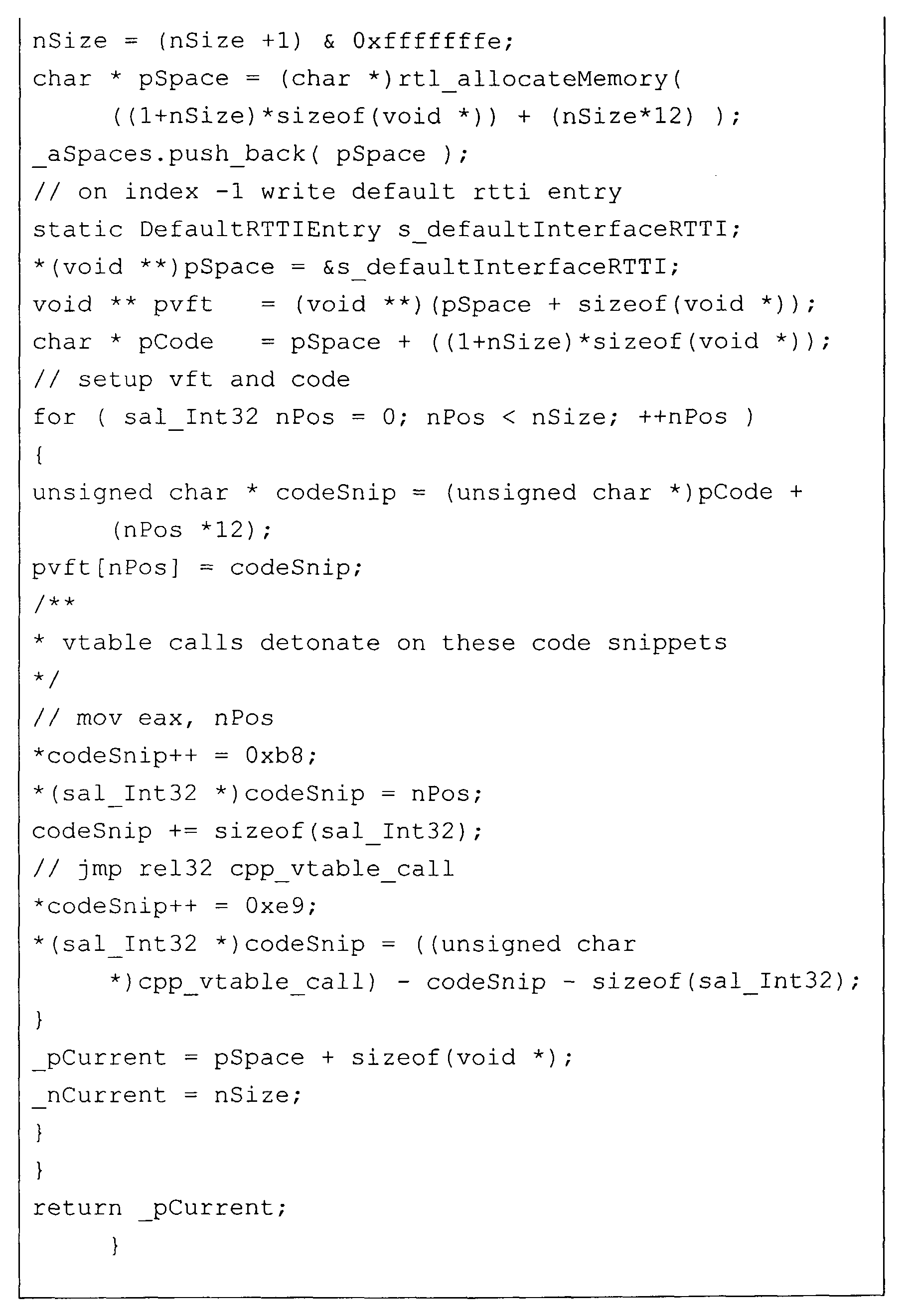
Figure 6 is an example of a call stack 600 of a virtual
function call that is stored in a memory 610 of
computer system 100 (Figs. 1A and 1B). The left-hand
column is the stack offset for the start of storage
location, and the right hand column gives the value
stored at each storage location.
The vtable for the C++ proxy, i.e., a function pointer
array to perform polymorphic calls on C++ objects,
determines which function should be called. Figure 7A
is an illustration of the vtable for this example that
correlates the slots in the table to the methods
handled by the C++ proxy. Recall, that every proxy has
to inherit the methods from UNO interface XInterface,
which are methods acquire, release, and queryInterface.
When the call to method bar (Table 7) is executed, the
call is directed to the C++ proxy. The only task of
the proxy vtable is to determine the call index of the
UNO method that is to be called. (See Fig. 7B)
Figure 8 is a process flow diagram of one embodiment of
the operations performed by a proxy 130 or 130A that in
this example is the C++ proxy. When method bar is
called, process 800 (Fig. 8) is started in
operation 801.
Initially, in determine slot operation 802 the C++
proxy executes method patchVtable (See Table 10) that
in turn calls method getMediateVtable (See Table 12).
Method getMediateVtable reaches an assembler snippet
that determines the vtable slot of method bar and calls
method vTable 810. This completes operation 802.
TABLE 13 is an example of one implementation of method
vTable 810.


Operation 802 transfers processing to prepare
stack operation 811 in method mediate 810. In
operation 811, the stack space is prepared for register
data, and then processing passes to call mediate
operation 812.
Call mediate operation 812 calls method mediate
that in turn looks up the called vtable index, gets the
attribute or method type description, and calls a
method that dispatches that actual call to the method
in the UNO environment. A process flow diagram of one
embodiment of method mediate 900 is presented in
Figure 9. Table 14 is an example of method mediate.


Method call check 901 of method mediate 900 determines
whether the call is a method call. If the call is a
method call processing transfers to acquire/release
check operation 910, and otherwise to attribute get
check operation 920.
Acquire/release check operation 910 branches to
acquire/release call operation 911 if the method call
is a call to either method acquire or method release,
because these calls can be executed without calling the
interface in the source environment. If the method
call is not a call to either method acquire or method
release, processing transfers from check operation 910
to query interface check operation 912.
Acquire/Release call operation 911 performs the appropriate method, which is a non-virtual call, and returns.
Acquire/Release call operation 911 performs the appropriate method, which is a non-virtual call, and returns.
Query interface check operation 912 determines whether
the method call is to method queryInterface. If the
method call is not to method queryInterface, check
operation 912 transfers to call Env1_to_Env2 with
Interface operation 930 and otherwise transfers to
registered interface available check operation 913. In
the current example, the call to method bar results in
check operation 912 transferring to operation 930.
Nevertheless, to complete the description of this
branch of method mediate 900, if there is a registered
interface in the source environment object for method
queryInterface, check operation 913 transfers to set
return value operation 914 and otherwise to call
Env1_to_Env2 with Interface operation 930. Asking
whether the interface is registered in the source
environment object is an optimization that eliminates a
call to the actual interface in the source environment.
Set return value operation 914 sets the registered
interface as the return value and returns.
If the call to the C++ proxy was not a method call,
check operation 901 transfers to attribute get check
operation 920. In this embodiment, there is either an
attribute get or an attribute set. If the call to the
proxy is an attribute get, check operation 920
transfers to prepare attribute get call operation 921
and otherwise transfers to prepare attribute set call
operation 922. Both operations 921 and 922 set up the
parameters for the call and transfer to call
Env1_to_Env2 with Interface operation 930.
An embodiment of method Env1_to_Env2 with interface for
the C++ proxy is presented in Table 15. Figure 10 is a
process flow diagram for one embodiment of method
Env1_to_Env2 with interface.


In Figure 10, read parameters operation 1001 reads the
parameters from the stack. All simple parameters are
directly accessed on the stack (up to eight bytes).
All complex structures, e.g., interfaces, are
referenced by a pointer. Since in this example UNO and
C++ types have the same binary size (See Table 5), only
interfaces need to be exchanged.
Read parameters operation 1001 transfers to convert
parameters operation 1002. Convert parameters
operation 1002, using the parameter type description,
converts the parameters read to the UNO environment and
transfers to allocate memory operation 1003. Allocate
memory operation 1003 allocates memory for the out
parameters returned by the call to the UNO interface,
and for the return value. Allocate memory
operation 1003 transfers processing to dispatch call
operation 1004.
Dispatch call operation 1004 calls, in this example,
method bar in UNO interface XExample. In general,
dispatch call operation 1004 dispatches a call to the
source interface (See Fig. 4). The call is executed in
the source environment and the results, if any, are
returned to operation 1004 that in turn transfers to
exception check operation 1005.
Exception check operation 1005 determines whether an
exception was thrown in response to the call. If an
exception was thrown, check operation 1005 transfers
processing to clean up operation 1110 and otherwise
processing transfers to convert parameters
operation 1020.
Clean up operation 1010 cleans up any temporary
parameters that were created in the call in
operation 1004. Operation 1010 transfers to throw
exception operation 1030 that in turn throws an
exception in the destination environment based upon the
exception received from the call to the source
environment.
If an exception was not thrown in the source
environment, convert parameters operation 1020 converts
any parameters that were returned from operation 1004,
e.g., out parameters and/or inout parameters using the
parameter type description, from the source environment
to the destination environment, and transfers to clean
up operation 1021. Clean up operation 1021 cleans up
any temporary parameters that were created in the call
in operation 1004 and transfers to convert return value
operation 1022. Operation 1022 converts any return
value from the source environment to the destination
environment so that both the return value and any
returned parameters are written back, in this example
to C++. Processing returns to mediate method 900 that
in turn returns to fill return registers 813 in method
vTable 810.
In fill return registers operation 813, if the type is
one of float, double, hyper, or unsigned hyper, an
appropriate action is taken to properly fill the return
registers. Otherwise, a 32-bit integer is placed in
register eax. See Table 13 for one embodiment of
operation 813.
The above example assumed that the original call was in
a C++ environment and was directed to a method of an
interface in the UNO environment. In the embodiment of
Figure 1A, another possibility is that a call is made
in the UNO environment, i.e., environment 120 to a C++
method in environment 150. In this case, the bridge
and proxy would be in the UNO environment.
Alternatively, in Figure 1B, the intermediate
environment is a UNO environment.
In this embodiment, struct cppu_unoInterfaceProxy in
Table 9 is used to instantiate the UNO proxy that wraps
a C++ interface. As explained more completely below,
when the proxy interface is called, a check is made to
determine if a method of the proxy interface has been
called. If a method was called, any input parameters
are converted using the type description and pushed on
a processor stack, and then a call is dispatched to the
demanded vtable slot in the source interface.
After execution of the dispatch call, the returned
information is checked to determine whether a C++
exception was generated. If no exception has occurred,
the inout/out parameters are reconverted. In this
example, the reconversion of inout/out parameters is
only important for values representing interfaces or
values containing interfaces, because the values of all
objects in the UNO environment are binary compatible on
a specific computing architecture.
The UNO proxy, as defined by Table 9, holds the
interface origin, i.e., the target C++ interface.
Thus, the UNO proxy can register at with the UNO
environment on the first execution of method acquire,
and can revoke itself on its last execution of method
release from its environment.
The UNO proxy manages a reference count for the proxy,
a pointer to the bridge of the UNO proxy to obtain the
counterpart mapping, the C++ interface the UNO proxy
delegates calls to, the (interface) type the UNO proxy
is emulating, and an object identifier (oid). The type
and object identifier are needed to manage objects from
environments, for proof of object identity, and to
improve performance. A proxy to an interface is not
needed if there is already a registered proxy for that
interface.
When the call to a method in the wrapped C++ interface
is executed, the call is directed to the UNO proxy.
Figure 11 is a process flow diagram of one embodiment
of the operations performed by the UNO proxy. One
example of computer code for this embodiment is
presented in TABLE 16.


Method call check 1101 of method dispatch 1100
determines whether the call is a method call. If the
call is a method call processing transfers to
acquire/release check operation 1110, and otherwise to
attribute get check operation 1120.
Acquire/release check operation 1110 branches to
acquire/release call operation 1111 if the method call
is a call to either method acquire or method release,
because these calls can be executed without calling the
interface in the second environment. If the method
call is not a call to either method acquire or method
release, processing transfers from check operation 1110
to query interface check operation 1112.
Acquire/Release call operation 1111 performs the
appropriate method, which is a non-virtual call, and
returns.
Query interface check operation 1112 determines whether
the method call is to method queryInterface. If the
method call is not to method queryInterface, check
operation 1112 transfers to call Env2_to_Env1 with
Interface operation 1130 and otherwise transfers to
registered interface available check operation 1113.
If there is a registered interface in the source
environment for method queryInterface, check
operation 1113 transfers to set return value
operation 1114 and otherwise to call Env2_to_Env1 with
Interface operation 1130. Set return value
operation 1114 sets the registered interface as the
return value and returns.
If the call to the C++ proxy was not a method call,
check operation 1101 transfers to attribute get check
operation 1120. In this embodiment, there is either an
attribute get or an attribute set. If the call to the
UNO proxy is an attribute get, check operation 1120
transfers to prepare attribute get call operation 1121
and otherwise transfers to prepare attribute set call
operation 1122. Both operations 1121 and 1122 set up
the parameters for the call and transfer to call
Env2_to_Env1 with Interface operation 1130. The call
is given the C++ interface pointer, a vtable index, and
all parameters necessary to perform the C++ virtual
function call.
An embodiment of method Env2_to_Env1 with interface for
the UNO proxy is presented in Table 17. Figure 12 is a
process flow diagram for one embodiment of method
Env2_to_Env1 with interface.


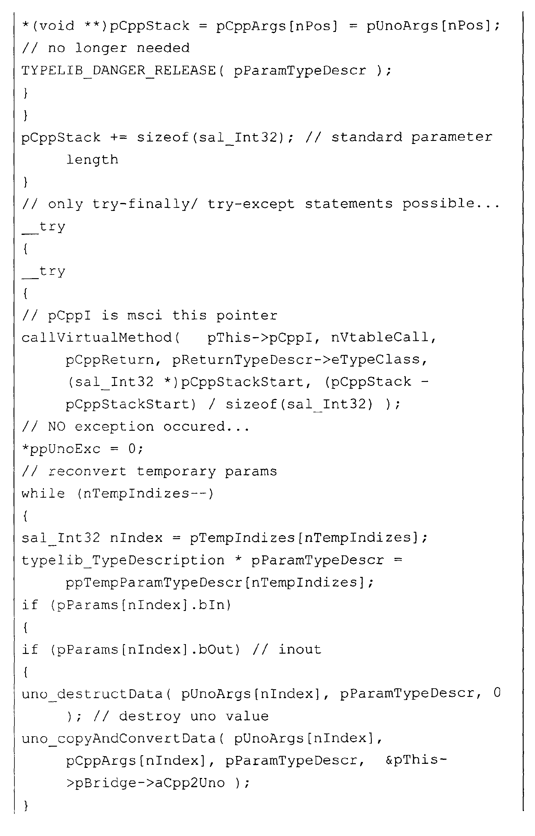


In Figure 12, read parameters operation 1201 reads the
parameters from the call. Read parameters
operation 1201 transfers to convert parameters
operation 1202. Convert parameters operation 1202 converts the parameters read to the C++ environment. A C++ call stack is built in memory. All simple types, up to eight bytes are put directly on the stack, and all other types are referenced by a pointer.
Operation 1202 transfers to allocate memory
operation 1203. Allocate memory operation 1203 allocates memory for the out parameters returned by the call to the C++ interface, and for the return value.
Allocate memory operation 1203 transfers processing to
dispatch call operation 1204.
Dispatch call operation 1204 performs a C++ virtual
call on the C++ interface. In one embodiment, method
callVirtual, an assembly function performing the
specific virtual call having the right registers set
(See Table 18), is called and passed an array that is
the call stack. The call is executed in the C++
environment and the results, if any, are returned to
operation 1204 that in turn transfers to exception
check operation 1205.
Exception check operation 1205 determines whether an
exception was thrown in response to the call. If an
exception was thrown, check operation 1205 transfers
processing to convert exception operation 1210 and
otherwise processing transfers to set exception
operation 1220.
Convert exception operation 1210 converts the C++
exception to the UNO environment, and sets an exception
out any with the converted exception. Operation 1210
transfers to clean up operation 1211 that in turn
cleans up any temporary parameters that were created in
the call in operation 1204 and transfers to return to
operation 1130.
If an exception was not thrown in the source
environment, set exception operation 1220 sets the
exception out any to zero, and transfers to convert
parameters operation 1221.
Convert parameters operation 1221 converts any
parameters that were returned from operation 1204,
e.g., out parameters and/or inout parameters, from the
source environment, i.e., the C++ environment, to the
destination environment, i.e., the UNO environment.
Operation 1221 also cleans up any temporary parameters
that were created in the call in operation 1204 and
transfers to convert return value operation 1222.
Operation 1222 converts any return value from the
source environment to the destination environment so
that both the return value and any returned parameters
are written back, in this example to the UNO caller.


In the above description of the example, various
methods were described and discussed. Figure 13A to 24
are specific examples of one embodiment of such
methods. In particular, in Figs 13A and 13B, an
embodiment of mapping an interface from the UNO
environment to the C++ environment is presented. See
Figure 4.
Fig. 14 is an example of a method free and a method for
revoking the proxy. Method free is called indirectly
by the C++ proxy described above when the reference
count goes to zero and the C++ proxy should be deleted.
Fig. 15 includes an example of a C++ proxy that
includes a method acquireProxy; an example of a method
releaseProxy that is used to revoke the C++ proxy from
the C++ environment structure; and a method
ccpu_cppInterfaceProxy to instantiate, acquire and
register the C++ proxy.
Figs. 16A and 16B include an example of a method free
that is called indirectly by the UNO proxy described
above when the reference count goes to zero and the UNO
proxy should be deleted; an example of a method acquire
that is used in acquiring the UNO proxy; and an example
of a method release that is used to revoke the UNO
proxy.
In Figs 17A and 17B, an embodiment of a method Mapping
for mapping from the C++ environment to the UNO
environment is presented. Figure 18 includes is a C++
implementation of the UNO proxy that includes a
constructor cpu_unoInterfaceProxy to instantiate,
acquire and register the UNO proxy; a method for
acquiring a mapping and a method for releasing a
mapping.
Figure 19 illustrates constructors for a mapping and a
bridge; and a method for freeing a bridge. Figure 20
is an embodiment of methods for acquiring and releasing
a bridge. Figure 21 includes a method
cppu_ext_getMapping to create a mapping between two
specified environments. Figure 22 is an embodiment of
a method to create the static part of an object Id.
The object id contains two parts, an object specific
part and a static part. Figure 23 is an embodiment of
a method to create a complete object Id, containing
both, the object specific and the static parts.
Figure 24 includes a method for acquiring a C++-uno
environment; a method for releasing a C++-uno
environment; and a method to initialize a C++-uno
environment.
In the following, further embodiments of the invention
will be described with respect to Figs. 25 - 38.
First, reference is made to Fig. 25. A first software
program 251, created with any convenient programming
language, for example C++, and compiled with a certain
compiler for C++, uses a first binary specification.
This first binary specification depends on both, the
programming language and on the compiler. The first
software program 251 may be, for example, able to
present numbers in graphical form. In order to
calculate the exact dimensions of the graphs the first
software program 251 may want to employ a second
software program 252, created with another programming
language, for example Java, and compiled by using a
certain compiler for Java. This second software program
252 uses the second binary specification for
communication.
The use of the second software program 252 by the first
software program 251 requires its initialization, for
example, by calling a loader function 255. The second
software program 252 may then initialize its sub-program
252a for creating the stub 254. The sub-program
252a must consider the limited functionality in order
to arrive at the desired stub 254, namely a module for
transforming commands and responses relating to the
requested limited functionality. Based on this limited
functionality, the sub-program 252a selects the
relevant mappings of the bridge 257 between the second
binary specification and the intermediate binary
specification.
The first software program 251 may correspondingly
initiate a sub-program 251a to create the proxy 253 in
a similar way, by employing the bridge 256 between the
first binary specification and the intermediate binary
specification. This sub-program 251a may be informed
about the limited functionality from the first software
program 251. However, it may also know this limited
functionality from the second software program 252 by
communicating via the communication channel 258. This
channel 258 may be any suitable real or virtual
connection which allows the transfer of data.
After the stub 254 and proxy 253 have been created they
are arranged so as to allow the communication between
the first software program 251 and the second software
program 252. Once this arrangement is effected the
first software program 251 sends the command to be
transformed to the proxy 253. The proxy 253 may
transform this command from the first binary
specification into the intermediate binary
specification. This intermediate binary specification
corresponds, for example, to the binary UNO
specification. The proxy 253 may transmit this command
in the intermediate binary specification to the stub
254. The stub 254 may transform the command from the
intermediate binary specification into the second
binary specification and may transmit the command then
to the second software program 252.
The second software program 252 may execute the
command, for example, the command to calculate the
dimensions of a graph and may generate a response for
the first software program 251. This response may be
transformed and transmitted by the stub 254 and the
proxy 253 from the second software program 252 to the
first software program 251.
The arrows shown in Fig. 25 between the first software
program 251, the proxy 253, the stub 254, the second
software program 252 and the loader function 255 show
the possible routes of communication. The arrows
between the proxy 253 and the bridge 256 and between
the stub 254 and the bridge 257 represent the
contribution of the bridges 256 and 257 to the creation
of the proxy 253 and the stub 254, respectively.
Fig. 26 represents an example for the initial
communication of a first software program 251 and a
second software program 252. The initial communication
between the two software programs 251, 252 is carried
out, before the creation of the stub 254 and of the
proxy 253 is initiated. Due to the different binary
specifications used by the two software programs 251,
252, namely the first and the second binary
specification, this initial communication will
regularly be extremely limited. It may be effected as
explained exemplary in the following.
In a first step 2600 the first software program 251 may
call a loader function 255 for the second software
program 252. The loader function 255 may be any known
loader function for this second software program 252. A
loader function for a program is a software module
which "wakes up" this program so that it carries out
certain functions. Herein, the loader function may be
addressed in one binary specification and may wake up a
program using a different binary specification.
However, the loader function is not suited to provide
any detailed communication between programs using
different binary specifications.
The loader function 255 may be used by the first
software program 251 from the beginning. This is the
case, if the first software program 251 knows or
assumes that the second software program 252 does not
use the same binary specification as itself, namely the
first binary specification. If this knowledge is not
present in the first software program 251, it may
simply try to call the second software program assuming
that it will understand the first binary specification.
In this case, the first software program 251 may only
employ the loader function 255 if the direct
communication with the second software program 252
fails and a corresponding message is returned to the
first software program 251.
In the calling step 2600 the first software program 251
informs the loader function 255 about the limited
functionality requested from the second software
program 252. Therefore, the loader function 255 must be
suited to receive and carry this information. In order
to provide this information to the loader function 255
the first software program 251 may hand over to the
loader function 255 the command to be carried out by
the second software program 252, so that the second
software program 252 may, on receipt of the call of the
loader function 255 decide itself which functionality
is needed, or the first software program 251 may
provide the loader function 255 directly with the
description of a limited functionality of the second
software program 252 which will be required by the
first software program 251.
In step 2601 the loader function 255 contacts and
initializes a reception function of the second software
program 252 to be able to transmit in the next step
2602 its information about the limited functionality
required from the second software program 252. In the
next step 2603 the second software program 252 analyses
the information received from the loader function 255
regarding the required limited functionality. After the
analysis of the limited functionality required the
second software program 252 initializes the creation of
a stub 254.
Fig. 27 shows the creation of a stub 254. The stub 254
has the task to transform commands sent by first
software program 251 to the second software program 252
from the intermediate binary specification into the
second binary specification used by the second software
program 252 and to transform responses sent by the
second software program 252 back to the first software
program 251 from the second binary specification into
the intermediate binary specification. Furthermore, the
stub 254 may be assigned the task to transmit the
transformed commands or responses to the recipients,
the second software program 252 or the proxy 253,
respectively.
In step 2700 the second software program 252 may
initialize a sub-program 252a for creating the stub
254. This sub-program 252a may be an integral part of
the second software program 252 or it may be as well a
separate independent software module which can be used
by this and potentially any other second software
program 252. Accordingly, the sub-program 252a may be
stored on the computer system or storage device on
which the second software program 252 is stored.
However, the sub-program 252a may also be stored on
another computer system or storage device to which the
second software program 252 has access.
In step 2701 the sub-program 252a receives from the
second software program 252 a description of the
limited functionality required from the second software
program 252. Then, in step 2702 the bridge 257 between
the second binary specification used by the second
software program 252 and the intermediate binary
specification is contacted. This bridge 257 provides a
mapping of at least all basic commands between the
mentioned two binary specifications. It may be stored
at any place accessible for the sub-program 252a. In
many cases there may exist a library with bridges for a
number of second binary specifications, assuming that
the intermediate binary specification used would be the
same for all intended operations.
From the selected bridge 257 the sub-program 252a
chooses in step 2703 the mappings necessary to use the
required limited functionality of the second software
program 252. This means all transformations, but not
more than these, must be selected which are required to
transform commands and responses which could arise when
using the relevant functionality. Finally, in step 2704
the sub-program 252a creates the stub 254 based on the
chosen mappings.
Fig. 28 represents in the form of a flow chart the
creation of the proxy 253. The proxy 253 has the task
to transform commands and responses between the first
binary specification and the intermediate binary
specification. It is insofar similar to the stub 254
which has, as it was described above, the task to
render these transformations between the second binary
specification and the intermediate binary
specification.
In step 2800 the first software program 251 may
initialize a sub-program 251a for creating the proxy
253. This sub-program may be an integral part of the
first software program 251, but may as well be separate
and independent from it. The sub-program 251a may be
accessible for a larger number of first software
programs 251. In step 2801 the sub-program 251a
receives from the first software program 251
information regarding the limited functionality
required from the second software program 252. This
information may be provided by passing on the actual
command the first software program 251 plans to send to
the second software program 252, so that the sub-program
251a may derive from this command the
information about the limited functionality, or the
first software program 251 may provide the sub-program
251a with a description of the limited functionality.
In an alternative embodiment the description of the
limited functionality may be received from the sub-program
252a for creating the stub 254. The sub-program
252a has the required description, because it has to
create the stub 254 according to the same description.
The description may be exchanged between the sub-program
252a and the sub-program 251a by any suitable
means of communication.
In yet an alternative embodiment the description of the
limited functionality of the second software program
252 may be derived directly by mapping the stub 254
into the first binary specification, in order to create
a proxy. This is possible, because the stub 254
reflects the required limited functionality in listings
between the second binary specification and the
intermediate binary specification which are necessary
for the transformation of commands and responses.
Therefore, the intermediate binary specification side
of the listings of the stub 254 may be taken as the
starting point for the creation of the proxy 253, which
is completed by adding the corresponding parts of the
listing in the first binary specification, as will be
explained below.
In step 2802 the sub-program 251a contacts the bridge
256, which provides a mapping of basic commands of the
first binary specification and the intermediate binary
specification, and builds, in step 2803, the desired
proxy 253.
The proxy 253 and stub 254 are then arranged to allow
the desired communication between the first software
program 251 and the second software program 252, as it
will be described in the following along the flow chart
of Fig. 29. The arrangement of proxy 253 and stub 254
requires that the path of exchanging transformed
commands and responses between the proxy 253 and the
stub 254 is defined.
Therefore, in step 2900 the second software program 252
informs the first software program 251 about the
address information necessary to contact the stub 254
via the communication line 258. The communication line
258 may consist of a simple data line for transmitting
binary address information which can be understood from
the first software program 251 without being able to
use the second binary specification in which the second
software program 252 communicates.
The first software program 251 provides, in step 2901,
the sub-program 251a with this received address
information, which, in step 2902, is passed on to the
proxy 253. The proxy 253 then contacts, for the first
time in step 2903, the stub 254, the address of which
is now known. In step 2903 the proxy 253 will also
transmit its own address information to the stub 254,
thereby allowing the stub 254 to contact the proxy 253.
Herewith, the proxy 253 and the stub 254 are arranged
for communication, that means they can send and receive
commands and responses to commands. This arranging step
is also referred to as binding.
Fig. 30 shows a computer system 300 which may be used
in the scope of the present invention. The computer
system 300 comprises an i-/o-interface 301, a central
processing unit (CPU) 302 and memory 303. It is
connected to an external memory 304 on which mass data
may be stored as well as software programs.
Furthermore, the computer system 300 is connected via
the i-/o-interface 301 to an output device 305, for
example, a screen, and to an input device 306, for
example, a keyboard.
The inventive method may be applied in the shown
standard computer system. The first software program
251 and the second software program 252 may be stored
in the internal memory 303 of the computer system 300,
as well as on its external memory 304. It is also
possible that one of the programs is stored on the
internal memory 303 and the other is stored on the
external memory 304. The proxy 253 and the stub 254
may be created by means of the CPU 302.
The method according to the present invention may also
be implemented and used on more than one computer
system, for example, in a network or in a client-server
system, as it is shown exemplary in Fig. 31.
Fig. 31 shows a client 310 which is connected to a
server 311. This connection may be a data line 312,
including any kind of permanent or temporary network,
like, for example, the internet. It is understood that,
instead of only one client, there may be a large number
of clients connected to the server. In the scope of the
present invention the first software program 251 may,
for example, be stored on client 310, while the second
software program 252 may be stored on server 311. The
exchange of commands and responses may be effected via
data line 312. For example, the bridges 256 and 257, as
well as any other potentially needed bridges may be
stored in one or more libraries on the server 311. The
sub-programs 251a and 252a may also be stored on the
server 311. In case the sub-program 251a is needed the
client 310 may request from the server 311 its
transmission via data channel 312.
It is understood that the present invention may also be
implemented in a variety of embodiments. In the
following one embodiment of the present invention is
described in more detail along Figures 32 to 35 and
Tables 1 and 2.
In response to a call of a first software program a
proxy and a stub will be created in the so-called proxy
factory and the stub factory, respectively. In order to
create a proxy and a stub three tasks have to be
carried out. First, the first software program using
the first binary specification has to be enabled to
communicate with to the second software program using
the second binary specification. Second, the stub
factory has to create a uno_interface implementation
considering the second binary specification based on
the limited functionality which delivers all calls
directed to the second software program to this second
software program. This uno_interface is program code
which is defined for the limited functionality. For the
generation of the uno_interface implementation the stub
factory employs information in the form of a type
description. This uno_interface implementation is also
referred to as the stub. Third, the proxy factory has
to create a uno_interface implementation for the first
binary specification. The proxy factory generates its
uno_interface implementation based on the information
of the type description. This uno_interface
implementation is referred to as the proxy.
The knowledge of the type description is necessary to
create the stub and the proxy, as described. This type
description is the full description of the limited
functionality, also called interface. It contains the
information about the required limited functionality of
the second software program which shall be used by the
first software program. The type description may refer
to different types shown in Table 1.
| Type | UNO | C++ | Java |
| Byte | Signed 8 Bit | Signed 8 Bit | Signed 8 Bit |
| Short | Signed 16 Bit | Signed 16 Bit | Signed 16 Bit |
| Ushort | Unsigned 16 Bit | Unsigned 16 Bit | Signed 16 Bit |
| Long | Signed 32 Bit | Signed 32 Bit | Signed 32 Bit |
| Ulong | Unsigned 32 Bit | Unsigned 32 Bit | Signed 32 Bit |
| Hyper | Signed 64 Bit | Signed 64 Bit | Signed 64 Bit |
| Uhyper | Unsigned 64 Bit | Unsigned 64 Bit | Signed 64 Bit |
| Float | Processor dependent: Intel, Sparc = IEEE float | Processor dependent: Intel, Sparc = IEEE float | IEEE float |
| Double | Processor dependent: Intel, Sparc = IEEE double | Processor dependent: Intel, Sparc = IEEE double | IEEE double |
| Enum | The size of an machine word. Normally this is the size of an integer. | The size of an machine word. Normally this is the size of an integer. | All enum values of one enum declaration are static object of a class. Each object contains a 32 bit value which represents the enumeration value. |
| Boolean | 1 Byte. | 1 Byte. | Boolean |
| Char | 16 Bit on WNT, W95, W98, Os2. 32 Bit on Unix | 16 Bit on WNT, W95, W98, Os2. 32 Bit on Unix | Unsigned 16 bit (char) |
| A pointer to a structure which have the following members: | A pointer to a structure which have the | ||
| long refCount; | following members: long refCount; | ||
| String | long length, wchar_t buffer[..]; The string in buffer is 0 terminated This is the rtl_wString structure in the rtl-library | long length; wchar_t buffer[...]; The string in buffer is 0 terminated. This is the rtl_wString structure in the rtl-library | java.lang.String" |
| The structure contains the members in | The structure contains the members in the | A class which is derived from | |
| Structure | the order of the declaration. The | order of the declaration. The memory | java.lang.Object" and contains members in the specified order. |
| memory layout is described at the | layout is described at the beginning of this | ||
| beginning of this chapter. | chapter. | ||
| The size is 4 + size of the largest type. In front of the union members are a | The size is 4 + size of the largest type. In | ||
| front of the union members are a long value (nSelect) which describe the position | |||
| Union | long value (nSelect) which describes | Not specified yet | |
| the position of the valid member (0 is | of the valid member (0 is the first). | ||
| the first). | |||
| A pointer to a structure which has the | A pointer to a structure which has the | ||
| following members: | following members: | ||
| void pElements; | void* pElements; | ||
| Sequence | long nElements, | long nElements; | It is a normal Java array. |
| long nRefCount; | long nRefCount; | ||
| The pElements are a memory area that | The pElements are a memory area that | ||
| contains nElements elements. | contains nElements elements. | ||
| A class which is derived from | |||
| Exception | Looks like a structure | Looks like a structure | java.lang.Exception" and contains the |
| members in the specified order. | |||
| The interface is a pointer to a function table, which contains 3 functions, | It is a pointer to a C++-Class which implements first the virtual methods queryinterface, acquire and release. | ||
| Interface | It is a normal Java interface. | ||
| A class which is derived from java.lang.Object". The members are a | |||
| This is a structure that contains a | This is a structure that contains a pointer | ||
| Any | pointer to a type description. The second member is a pointer to the | to a type description. The second member | class, which describe the type of the value. |
| value stored in the any. | is a pointer to the value stored in the any. | A second member which is the value of the any. | |
| Void | No memory representation | No memory representation | No memory representation |
Many of these types are self-explaining and known in
the art. Nevertheless, the most relevant types of the
type description will be explained in more detail
below.
"Interfaces": All interfaces employed in connection
with the present embodiment are derived from a Super-Interface.
Each interface contains at least three
methods. The two methods "acquire" and "release" are
necessary to control the lifetime of the interface. The
third method "queryInterface" is used to navigate
between different Interfaces. A XInterface includes
only these three methods. All other interfaces are
derived from this XInterface. The methods and
functionalities requested by the first software program
will be part of the interface.
In Java, for example, interfaces are mapped to Java
interfaces which could be normally implemented. The
methods acquire and release are not mapped to the Java
program since this methods do not exist in Java. The
lifetime of the proxy, the stub and the relevant
information in the second program will be controlled by
a garbage collector. The programming language Java
delivers basic types by value and non-basic types by
reference. All calls are specified by value except
interfaces. So in Java all non-basic types returned or
delivered through out parameters are by value, which
means that the implementation must copy it before
return or deliver.
In C++, for example, interfaces are mapped to pure
virtual classes. In order to automatically control the
lifetime of interfaces a template called "Reference"
will be used. All return, parameter and member types
are "References" (e.g.: Reference< XInterface >). The
"Reference" acquires the interface when it is
constructed and releases the interface when it is
destructed.
"Structure": A structure is a collection of elements.
The type of each element is fixed and it cannot be
changed. The number of elements is fixed.
"Exceptions": An exception is a program control
construct beside the normal control flow. One major
feature of exceptions is, that it is simpler to
implement the error handling. Exceptions are similar to
structures since they are also a collection of elements
and each type of each element is fixed and cannot be
changed and the number of elements is also fixed. An
additional feature of exceptions is that they can be
thrown by a method. All exceptions which can be thrown
by a method must be declared at the method, except for
the called "RuntimeException" which always can occur.
All exceptions must be derived from "Exception". If an
exception is declared at a method it is allowed to
throw all derived exceptions. The caller of a method
must respond to this behavior.
In Java, for example, all exceptions are derived from
the "java.lang.Exception". The exceptions are declared
at the methods.
In C++, for example, the exceptions are generated as
structures. An exception is thrown as instance (e.g.:
throw RuntimeException()). At the other side the
exception should be caught as reference
(...catch(RuntimeException & ) { ... }).
"Union": A union contains one element. The declaration
of a union specifies the possible types.
"Array": An array contains any number of elements. The
type of the elements is fixed and cannot be changed.
"Any": An any contains one element. All types of
elements are possible. An any contains a reference to
the value and the type description of the type. With
the type description the bridge can transform the
value, if necessary.
In Java the any is, for example, represented by the
class "Any", which contains a class as type description
and a "java.lang.Object", which is the value. The basic
types are wrapped to their proper classes. For example,
a boolean value is an object of the class
"java.lang.Boolean", which contains the value.
In C++ the any is represented through the class "Any".
Each type generated by a C++ codemaker implements an
function "getCppuType". This function is used to
implement the template access operators "<<=" and
">>=". These operators insert and extract the value of
the any.
"Sequence": A sequence is a generic data type. It
contains the number of elements and the elements. In
Java the specification of an array fulfills this
specification. This is not true for C++. The array in
C++ does not contain the number of elements. It is not
possible to return a C++-array, e.g. Char[] getName()
is not possible. It is difficult to manage the lifetime
between the called and the caller, if only a pointer is
returned. Therefore, in C++ a sequence is a template
with the name "Sequence". The implementation contains a
pointer to a structure which contains a pointer to the
elements, the number of elements and the reference
count. So it holds the binary specification. It is
cheap to copy this sequence, because only the reference
count is incremented.
The type description may exist or it may be runtime
created. Each existing type is stored in a type
repository along with the corresponding type
description. The types of the type description are
accessible through the full name of each type in the
type repository. For example, the full name of the type
"Xinterface" may be "com.sun.star.Xinterface".
In a type repository the types needed for any type
description are stored in any appropriate way. If the
API (application program interface) of the type
repository is c-style, it is directly, that means via a
binary representation, accessible from many binary
specifications and it is quickly transferable. Since
the type description of each element may be used during
the generic marshaling of a call, the access
performance of the type repository API is critical.
Therefore, it is useful to use c-style structures,
which describe each type. In addition, there may be
interfaces declared which specify the access to the
type repository. The module of this interface is
"com.sun.star.typelib".
All functions or type declarations have the prefix
"typelib_". All elements are reference counted. All elements start with the structure
"typelib_TypeDescription". It is possible to cast all descriptions to this type. The function
typelib typedescription newInterface will be used to create an interface description. The descriptions of structures, unions and sequences are created with the function typelib_typedescription_new. The description of the base type is initially part of the type repository. The function to get a type description is typelib_typedescription_getByName.
The Java API to the type repository is different for
two reasons. First, Java cannot access the binary
representation of the type descriptions directly.
Second, the Java runtime system provides an API (core
reflection) similar to the type repository API.
Unfortunately, the features "unsigned", "oneway" and
"out parameters" are missing in this API. For this
reason, additional information is written into the
classes.
The representation of the types depends on the
hardware, the language and the operating system. The
base type is swapped, for example, if the processor has
little or big endian format. The size of the types may
vary depending on the processor bus size. The alignment
is processor and bus dependent. The alignment of the
data structure is defined through the following
algorithm:
Structure members are stored sequentially in the order in which they are declared. Every data object has an alignment-requirement. For structures, the requirement is the largest of its members. Every object is allocated an offset so that offset % alignment-requirement == 0
Structure members are stored sequentially in the order in which they are declared. Every data object has an alignment-requirement. For structures, the requirement is the largest of its members. Every object is allocated an offset so that offset % alignment-requirement == 0
If it is possible that the maximum alignment can be
restricted (Microsoft C/C++ compiler, IBM C/C++
compiler) than the size maximum alignment is set to
eight. Under this condition the alignment is set to
min( n, sizeof( item ) ). The size is round up to the
largest integral base type.
For the Microsoft and IBM C/C++ compiler the alignment
of structure is set to eight using the "#pragma"
statement. Table 1 shows the binary UNO, C++ and the
Java types.
In order to address the proxy factory to generate the
proxy the first binary specification has to be
denominated. This will be a string, because it is
extensible and the risk of double names is low. Then a
tool for selecting the desired bridge is called. The
first parameter for this tool is the "first binary
specification" and the second parameter is the
intermediate binary specification "UNO". Then a
function is called for selecting the desired mapping of
the bridge. The name of the function is, in this
example, "getMappingFactory". A call to create a proxy
in "objective c" will be
"getMappingFactory ("objective_c", "uno")". The
implementation of the function will search a shared
library named "objective_cuno" to find the right
library that contains the proxy factory. In Java the
tool may search for a class of name "objective_cuno".
In order to create a stub merely the parameters of the
function have to be changed, in our example to
"getMappingFactory("uno", "objective_c")". A stub
implements the uno_interface. In the dispatch function
the stub must call the right method of the original
object. This is simpler in a programming language like
Java, which has a "core reflection API", than in a
programming language like C++, which has no binary
standard and no API to call virtual methods.
In creating a proxy the proxy factory must generate
method code to implement each method specified in the
interface to be created. The only information to do
this is a type description of the interface. For
example: In Java (1.1) a binary class file (*.class)
must be generated and loaded with the class loader. In
the absence of a loader which can directly load binary
classes a loader has to be provided. In C++ virtual
method tables must be generated which delegate each
call to the uno_interface. In the absence of a binary
C++ specification individual compilers (version,
switch,...) may have to be explored in order to
implement this.
The proxy and the stub factory employ bridges for the
generation of the proxy and the stub, respectively. A
bridge implements infrastructure to exchange interfaces
between two environments and is bidirectional.
An environment contains all objects which suffices the
same specification and lies in the same process address
space. The environment is specific for a programming
language and for a compiler. For example, an object
resides in the "msci" environment, if it is implemented
in C++ and compiled with the Microsoft Visual C++
compiler. It may also be session specific for some
reason, e.g. when running multiple Java virtual
machines in one process. In the latter case these
virtual machines have to be distinguished. However,
this case is not a common case.
Regularly, the environment is the area in which the
same binary specification is employed. Therefore, the
first software program and the second software program
belong to different environments.
Each bridge is implemented in a separate shared
library. The name of the library is a connection of two
environment names with an underscore ('_') between the
names. Each bridge library exports two functions called
"uno_ext_getMapping" and "uno_initEnvironment". The
first function is called to get the mappings.
In order to get a mapping uno_getMapping() has to be
called. There is also a C++ class called cppu_Bridge
which can be used with the source and destination
environment names. The uno_ext_getMapping() call then
receives its source and destination environments. The
bridge library cannot be unloaded while any code of it
is still needed. So both mappings and any wrapped
interface (proxy) that is exported needs to modify a
shared library wide reference count. If the shared
library can be unloaded the reference count goes to
zero.
The intention of an environment structure is to provide
common functions like acquireInterface() and to know
all proxy interfaces and their origins. This is
specifically important because of the object identity
of an interface. The proxy, the stub and the second
program are defined to provide the same instance of the
XInterface any time it is queried for it. This is
important to test, if two interfaces belong to the same
object (e.g. testing the source of an incoming event).
When interfaces are mapped around some environments in
space, they must provide the same XInterface in each
environment (e.g. in C++, equal XInterface pointers).
It is not recommended to only keep an eye on this
object identity issue. It is well recommended to reuse
any interface, i.e. rejecting the production of proxy
interfaces as often as possible, because each
constructed proxy interface leads to another
indirection when called, and there will of course be
many interfaces.
So an environment knows each wrapped interface (proxy)
running in it and the origin of each of these
interfaces. Table 2 shows the representation of an
environment.


Environments, as defined above, consist of several
fields. The first fields are used for identifying the
environment, for specifying the hardware, the process,
and maybe a session specific ID. There is also a
context pointer which can be used for specific classes
of environments, e.g. when it is known that there is a
Java environment the virtual machine pointer can be
stored there.
In order to use environments, these environments
regularly have to be registered. An existing
environment may be obtained by calling
uno_getEnvironment(). A new environment can be created
by either implementing it directly or by using a simple
default implementation, which is frequently also
sufficient, by calling, in the given example,
uno_createDefaultEnvironment() with the environment's
name and its acquire and release function for
interfaces.
In order to improve the performance the bridges should
use the shortest way between two environments.
Especially, if there are programs instantiated in the
identical environment, the communication between them
should be direct and not over a proxy and a stub.
Mapping is the direct way to publish an interface in
another environment. That means an interface is mapped
from a source environment to a target environment so
that methods may be invoked on a mapped interface in
the target environment which are delegated to the
originating interface in the source environment. A
mapped interface may also be called a proxy or a stub.
Mapping an interface from an environment A to an
environment B requires that several steps are
performed: First, the origin of the interface from
environment A has to be retrieved (call
getInterfaceOrigin() on environment A). For this
purpose, the environment A looks into its proxy
interfaces table to check if there is such an interface
already known (pointer and type). If the answer is no,
then this interface must originally come from
environment A, or else it must originate from any other
environment and its origin must be known, since each
proxy interface must have been registered with its
origin. Second, an existing proxy interface has to be
looked for in environment B with the same origin and
type (call getInterface() on environment B). If a proxy
interface of that origin and type is already in use in
environment B, then this interface is acquired, or else
a new proxy has to be constructed wrapping the source
interface from environment A. The fresh proxy interface
is then to be registered via registerInterface() on its
first acquire() and revoked via revokeInterface() on
its last release() from its environment. This second
step has to be synchronized with other threads in order
to get access to mapping tables of an environment by
getting an access interface (lockAccess()) from the
environment. Then an unlockAccess() function has to be
called.
The stub is encapsulated in an object which delivers
and transforms the binary specification adapted calls
to the stub. This object is the proxy of a stub in the
first binary specification. This proxy which calls and
attributes access will be similar with the binary
specification from which the call was made. The calling
to the stub is shown in Fig. 32.
First in step 321 a type save call (e.g. acquire,
queryInterface, ...) is made at the proxy 253. This
type save call will be transformed by the proxy 253 to
a corresponding call in step 322 and dispatched to the
stub 254 in step 323. After that, the return value of
this call is transformed in step 324 to the type
expected by the binary specification.
The proxy is binary specification specific. So it is
possible to put this object seamless into the binary
specification.
A stub object is also created which implements an
uno_interface and transforms and delegates the calls to
the second program implemented in a specific
programming language (e.g. C++, Java,...). Fig. 33
describes a call through a stub 254 to the second
program 252.
In a first step 331 the dispatch function is called. If
proxy and stub are running in the same process, the
dispatch function of the stub is directly called by the
proxy. In a distributed environment this is not
possible. In this case the abstract virtual channel has
to provide this functionality. On the proxy side the
proxy will accept the request and transmit it to the
stub side. On the stub side the stub has to call the
dispatch function.
The stub 254 detects the interface and the method which
should be called at the second program 252. Then in
step 332 the call was transformed into a specific
binary specification by the stub 254 and the second
program 252 was called in step 333. After that, the
return value was re-transformed to the other binary
specification in step 334.
The stub makes all transformations to the binary
specification in which the second program is
implemented. This is in this example the second binary
specification. This makes it possible to implement the
second program in the second binary specification. For
example: In C++ exceptions, multiple inheritance and
derivation can be used. In addition to the binary
specification there are the type descriptions which
must be mapped in the binary specification of the
second program.
In order to enable to call from one binary
specification or object model to another the stub and
the proxy have to undergo a binding process. The proxy
allows to call from one binary specification to the
uno_interface, while the stub allows to call through
the uno_interface to the second program. The binding of
the stub and the proxy is initiated by the first
software program 251 and is shown in Fig. 34. In a
first step 341 the generation of a stub with the binary
UNO specification in the stub factory 342 is shown. In
a second step 343 a proxy is created based on the
generated stub in the proxy factory 344.
Each call to the proxy is delivered to the stub. The
stub prepares the call and calls the second program in
the corresponding binary specification. Fig. 35 shows
exemplary the call from a first software program 251 in
a programming language like "objective c" to a second
software program 252 which may be implemented in the
programming language C++.
The first software program 251 uses the programming
language "objective c". The proxy 253 makes the
interface available to the first software program 251
in the first binary specification. This means the first
software program 251 uses the first binary
specification to manipulate the second software program
252. For example, this may be effected by the call
"char * pOldText = [myObject changeText: "test"]" in
step 351. The proxy 253 transforms the parameter of
type string to the binary specification in step 352.
Then, the proxy 253 dispatches in step 353 the call to
the stub 254. The necessary information, including a
method type description, parameters, an address for the
return value and an address for the exception, if any
occurs, is delivered to the stub 254. The stub 254
transforms in step 354 the string from the binary UNO
specification to a second binary specification string.
The stub 254 calls the right method at the second
software program 252 in step 355, in our example
"pComponent->changeText("test")". The stub 254 must
catch all kind of exceptions thrown by the second
software program 252. If the method returns normally,
the string is transformed in the step 356 to the binary
UNO specification and stored at the place given through
the dispatch call. If an exception is thrown, the
exception is transformed and stored at the address
given through the dispatch call. After the dispatch
call returns the proxy 253 transforms in step 357 the
string to a first binary specification string and
returns from the "changeText" call. If the call
terminates by an exception, the exception is returned
to the first software program 251. It is up to the
first binary specification in which manner the
exception occurs (the "objective c" language does not
support exception handling).
Fig. 36 shows the advantage of the binary UNO
specification as an intermediate binary specification
as it was described above. In a first step 361 the
first software program 251, for example written in the
programming language C++, transmits one command in a
first binary specification, in this example the command
"setText("a test")", to the proxy 253. Regularly, the
first software program will transmit more than one
command, for example, also the acquire, the release and
the queryInterface command as described above. This
command will be transformed by the proxy 253 in the
next step 362 from the first binary specification into
the binary UNO specification. The command in the binary
UNO specification contains the following information:
the parameter "a test", the return address, an address
for the exceptions, and the type description of the
command "setText". The type description of this command
will include, in this example, the name of the command
(setText), the type of the parameter and the return
type. This transformed command will be transmitted to
the stub 254 in the step 363. Then, the stub 254
transforms in step 364 the command from the binary UNO
specification into the second binary specification,
employed by the second software program 252 which was
written, for example, in the programming language Java.
The stub 254 employs for this transforming step only
one dispatch mechanism. This is a mechanism which will
be employed for each command transmitted by the proxy
253, since it is able to dispatch the name of the
command and the other relevant information to the
second software program 252. In the final step 365 the
second software program 252 executes the command
"setText". The response to this command will be
transmitted and transformed in a corresponding way.
Fig. 37 shows a scenario where between the proxy 253
and the stub 254 an interceptor 370 is inserted. This
means, that the stub 254 and the interceptor 370 are
created in a first step, while in a second step the
stub 253 is created based on information about the stub
254 and the interceptor 370. Therefore, the proxy 253
will communicate only with the interceptor 370 and not
with the stub 254.
Such an interceptor may be able to carry out, for
example, an accounting function or a security check
function. If, for example, the first software program
251 wants to use a functionality of the second software
program 252, the interceptor may be able to discover if
the user of the first software program is authorized to
use this function and to debit the account of the user,
if the user has to pay for this functionality. Such an
interceptor may also be used, for example, to help
debugging the communication between a first software
program 251 and a second software program 252. In such
a case the interceptor may provide an alarm function
which will be initiated, if a predefined functionality
is called. If the functions requested from the second
software program 252 may be grouped as one transaction,
it may also be possible that an interceptor cancels all
already executed functions of this group, if one
function fails. Such an interceptor has the advantage
that only one interceptor may be employed for every
function or method of an interface and for all binary
specifications of software programs which communicate
via the intermediate binary specification used by the
stub 254 and the proxy 253.
Fig. 38 shows a flow chart representing the use of an
interceptor as checking and accounting function for a
fax service. In this example, a user of a first
software program using a first binary specification
wants to use the fax service of a second software
program using a second binary language. This fax
service may distinguish between two kinds of users. A
standard user may have to pay for each fax and a
premium user may have to pay a monthly standard fee.
In order to enable the communication between the two
software programs a stub and a proxy will be created
and combined and arranged together with a specific
interceptor in a way shown in Fig. 37. Then, the
following steps may be carried out in using the
invention.
In step 3800 the first software program sends a command
including the desired fax number, the corresponding fax
file and the identity of the user to the proxy. The
proxy transforms this command into the intermediate
binary specification and forwards it to the interceptor
in step 3801. The interceptor checks in step 3802
whether the user is a standard user.
If the answer is "Yes", that means the user is a
standard user, the interceptor may deteremine in step
3803 whether the user has enough credit. If the answer
to this question is "No", the user will be informed
about his insufficient credit status and about the fact
that the fax was yet not sent in step 3804. If the
answer is "Yes", that means that the user has enough
credit, the interceptor will initiate, in this example,
the debiting of the user's account in step 3805 and
forward the received command to the stub in step 3806.
If the answer in step 3802 is "No", that means the user
is a premium user, the interceptor will forward the
command received from the proxy directly to the stub in
step 3806. The stub will transform this command from
the intermediate binary specification into the second
binary specification and forward this command to the
second software program in step 3807. Then the fax may
be sent.
In the following further embodiments for dynamically
dispatching function calls from a first execution
Environment to a second execution environment will be
described.
creating a first execution environment object including said second binary specification.
creating a second execution environment object including said first binary specification.
using said bridge object to generate a proxy wrapping an interface in said second execution environment.
dispatching said corresponding method call for execution in said second execution environment to said second execution environment by said proxy interface.
using a type description to convert parameters from said first execution environment to said second execution environment.
executing said corresponding method call in said second execution environment, and returning results of said execution to said proxy interface.
using a type description to convert said returned results from said second execution environment to said first execution environment.
executing said corresponding method call in said second execution environment, and returning results of said execution to said proxy interface.
using a type description to convert said returned results from said second execution environment to said first execution environment.
In the following a further embodiment of a computer program product will be described.
creating a first execution environment object including said second binary specification.
creating a second execution environment object including said first binary specification.
dispatching said corresponding method call for execution in said second execution environment to said second execution environment by said proxy interface.
using a type description to convert parameters from said first execution environment to said second execution environment.
executing said corresponding method call in said second execution environment, and returning results of said execution to said proxy interface.
using a type description to convert said returned results from said second execution environment to said first execution environment. A computer storage medium may have the following elements.
an extended environment structure.
a type name.
a method acquire.
a method release.
a pointer to said extended environment structure.
A method for enabling a first software program using a
first binary specification in a first execution
environment to employ a limited functionality of a
second software program using a second binary
specification in a second execution environment first
creates a bridge in the first execution environment.
Using the bridge, a proxy wrapping an interface to the
limited functionality of the second software program in
the second execution environment is created in the
first execution environment. The proxy is used to
access the limited functionality of the second software
program in the second execution environment.
CHAPTER C describes a method and system for remote
control and interaction with a run time environment
component, e.g. in the network portal system of CHAPTER
A.
Chapter C relates to runtime environment component
services, and in particular to a runtime environment
component services provided by a first computer system
to a second computer system over a communication
network, e.g. in the network portal system of CHAPTER
A.
Today, many computer networks are arranged as client-server
systems. In a client-server system, a
potentially large number of smaller computer systems,
like laptops or handhold organizers, called clients,
are, temporarily or permanently connected to a larger
computer system, called server. The connection between
the clients and the server may be effected, for
example, via the Internet.
In client-server systems, a client typically has
limited storage and processing capabilities.
Nevertheless, many software programs are executed on
the clients. One prior art way to make a software
program on the server available to clients was to use a
browser on the client. The browser was used to
transfer a relatively large software program or a
relatively large part thereof from the server to a
client so that the software program could be executed
locally on the client. This method required that the
software program or a part thereof be stored and
processed on the client.
For this purpose, the client must have sufficient
storage capacity and processing capability to execute
the software program locally. These requirements may
conflict with the aim of having smaller and smaller
clients, including cellular telephones, which may not
have enough storage capacity or processing capability
for storing or processing, respectively, large software
programs or large parts of software programs.
Frequently, a software program requested by a client
for execution is transferred every time the software
program is executed. The speed of this download
depends on the available data transfer capacity of the
network connecting the server and the client. Here,
frequently the available bandwidth of the network
connection is decisive. In many instances the
described client-server systems would be undesirably
slow in executing a software program, because the
download takes too much time.
Therefore, software programs, which are called
frequently for execution on a client, may be
permanently, or at least for some time, stored on the
client. This leads, however, to the task of regularly,
and maybe even individually, updating a potentially
large number of clients, if relevant software programs
are amended or updated. Considerable administration
efforts for client-server systems may be the
consequence.
It is also known to include into a software program
executed on a client procedures, which are executed on
a server. A prior technique to implement this used
CORBA. For example, certain more complicated
calculations, the result of which may be needed on a
client, were carried out on a server connected with the
client over a network. However, this required that the
program developer include particular commands into the
code of the software program to be executed on the
client for calling the software program to be executed
on the server, in the given example the calculation
program. This was not only cumbersome, but also led to
incompatibilities when the software program to be
executed on the server was amended.
It is further known to allow a user to initiate
execution of a program server from a client and to
review the results of the program execution on the
client. This approach is used in the UNIX X-Windows
system. However, this approach did not permit the
client to control the program and did not permit
integration of server side functionality into the
client side environment at the level of function calls.
It is desirable to provide improved access from a first
computer system to resources available at a second
computer system.
According to one embodiment, a user device, a first
computer system, includes a lightweight component that
receives user input actions for a runtime environment
component that is executing on a second computer
system. The lightweight component sends a remote input
action command to a user interface infrastructure that
is executing on the second computer system.
In response to the remote input action command, the
user interface infrastructure sends a local input
action command to the runtime environment component
that processes the command, and issues a local output
command to the user interface infrastructure that in
turn sends a remote output command to the lightweight
component on the user device. In response to the
remote output command, the lightweight component causes
an output on the user device. This output could be
redrawing a display, playing a sound, or perhaps
routing information to a local printer.
All the management of components in the user interface,
management of data and so on is performed on the second
computer system and so the lightweight component only
has, for example, to update the display to reflect the
state of the runtime environment component as indicated
by the remote output command received. It appears to
the user that the runtime environment component is
executing locally on the user device despite that fact
that the user device is only functioning as an
input/output device for the runtime environment
component.
In one embodiment, a method for presenting a runtime
environment component service by a first computer
system to a second computer system over a communication
network is performed by the first computer system. The
method includes generating a user interface
infrastructure on the first computer system. The user
interface infrastructure receives graphic user
interface events from the second computer system and
sends remote graphic user interface commands to the
second computer system. The user interface
infrastructure is used to initialize the runtime
environment component service. The runtime environment
component service sends graphic user interface commands
to the user interface infrastructure.
In another embodiment, the first computer system
receives a remote input action command for a runtime
environment component service via a communication
network. The remote input action is being generated in
the second computer system by a lightweight component
corresponding to the runtime environment component
service. A local input action command is transmitted
to the runtime environment component service in
response to the remote input action command. The local
input action command is processed by the runtime
environment component service, and a local output
command is generated by the runtime environment
component service for a graphical user interface. A
remote output command is transmitted to the lightweight
component in response to the local output command.
In yet another embodiment, a method for enabling a user
device to run a runtime environment component on
another computer includes running a browser on the user
device. A lightweight component is run within the
browser. The lightweight component receives user input
actions on the user device and generates corresponding
user interface events to the another computer for
processing by the runtime environment component.
A computer program product, in one embodiment,
comprises computer code including a remote frame window
class that in turn includes a remote output device
interface and a remote frame window interface. The
computer code optionally includes any or all of a bean
frame class comprising a frame interface; a bean window
class including an event handler interface and a window
peer interface; and an abstract windowing toolkit.
According to a further embodiment a method is provided
for presenting runtime environment component services
by a first computer system to a second computer system
over a communication network, said method being
performed by said first computer system, and comprising
the steps of:
The invention comprises also a method for providing
runtime environment component services from a first
computer system over a communication network to a
second computer system, said method being executed on
said second computer system and comprising the steps
of:
Thus, the runtime environment component services are
presented by a first computer system to a second
computer system over a communication network, whereby
upon receiving a request for a runtime environment
component service transmitted by said second computer
system over said communication network, the first
computer system executes a runtime environment
component for producing a result according to said
received request, and transmits - over said network - a
response comprising said result to said second computer
system.
In the context of the present invention a lightweight
component is a software program which is able to
request a runtime environment component service,
wherein the lightweight component corresponds to this
runtime environment component service, and wherein the
lightweight component is tiny enough to be downloaded
from the first computer system onto the second computer
system via the network connecting the first with the
second computer system within a time t significantly
smaller than the time it would take to download the
whole runtime environment component to which it
corresponds.
The time t shall particularly, but not necessarily, be
less than (8 N / CB) + t1, wherein N is the size of the
runtime environment component in bytes, CB is the
average bandwidth of the network connection between the
first and the second computer system, and t1 is the time
needed to initialize the runtime environment component
providing the requested service in its respective local
environment on the first computer system. In today's
commonly available network connections between servers
and clients the time t will typically be about ten
seconds.
When using networks commonly used at present for the
connection of clients and servers this time condition
amounts to a scope of the lightweight component which
is - measured in necessary storage space - less than
ten or even less than five percent of the scope of the
totality of the runtime environment components which
can be requested by it, including any auxiliary
software programs which these runtime environment
components need to be executed in the first computer
system.
Correspondence of the lightweight component with the
runtime environment component service means, in this
context, that the lightweight component must offer the
second computer system access to the runtime
environment component service made available by it. If
a plurality of runtime environment component services
is made available by the lightweight component, which
will frequently be the case, the lightweight component
corresponds to this plurality of runtime environment
component services in the explained sense.
The inventive methods enable a second computer system
to use results produced by a first computer system. The
load of holding, maintaining and administrating these
runtime environment components, as well as executing
these runtime environment components, is burdened onto
said first computer system. Nevertheless, said second
computer system can profit from these runtime
environment component services as if the relating
runtime environment components were present locally on
said second computer system. Therefore, additional
functionality is provided even to those computer
systems which are not powerful enough to store and / or
execute the full range of runtime environment
components, as for example notebooks, handheld
computers, organizers and mobile telephones. Since said
first computer system and said second computer system
exchange requests for services and responses to said
requests, rather than exchanging programming code to
perform the services, the amount of data transfer
between both computer systems is considerably reduced.
This shortens communication time (on-line time) and
leads to faster running software programs on the second
computer system.
The inventive methods are particularly interesting for
use with a client/server environment. In that case, the
first computer system takes over the role of a server,
whereas the second computer system is one of the
clients. The network may be a local network or a wide-area
network, as for example the Internet.
As an example, said runtime environment component
services may relate to graphic functions, word
processing functions, document editing functions,
mathematical functions, table calculation functions, or
printing functions. Said runtime environment components
may be, for example, of the form of application
programming interfaces or runtime components.
The runtime environment component services offered by
the first computer system are requested, according to
the present invention, by means of a request generated
by a lightweight component on the second computer
system. This lightweight component may issue this
request in response to a call of a software program
being executed on the second computer system. However,
the lightweight component may also be or have a user
interface, so that no additional software programs need
to be executed on the second computer system.
The runtime environment components as well as possible
software programs calling for their services may
comprise compiled program code to be executed or script
code to be interpreted.
As a general advantage of the invention, all the
characteristics of the runtime environment components
residing on said first computer system, for example a
program interface and a runtime environment, can be
made fully available for use by said second computer
system. If new components or releases of components are
added to said first computer system, these can be made
immediately available to the second computer system
without any significant modifications or additions
required on said second computer system. This central
administration of runtime environment components
reduces the load of administration on said second
computer system and on a client/server system in
general.
Said request and / or said response sent over said
communication network may be compliant with a
predetermined communication protocol, in particular
with the Internet protocol.
In particular, if the communication network is an open
wide-area network, said request and / or said response
may be transmitted over secure channels. For example,
encryption / decryption technologies may be applied for
the communication between said computer systems.
Said request and / or said response may comprise
identification data of said first computer system,
identification data of said second computer system,
identification data of said runtime environment
component service, and input data to said runtime
environment component service.
It is to be understood that said first computer system
may present said runtime environment component services
to an arbitrary number of second computer systems
independently from each other. On the other hand, a
second computer system may transmit its requests
selectively to different first computer systems. The
communication network may be of any type suitable for
communication between computer systems, including wired
and partially or totally wireless. The computer systems
may be of any type of processing environments, and of
any size. They may be embedded into other systems.
The invention can be implemented by a computer system
comprising computer program code or application code.
Computer program code or application code may be
embodied in any form of a computer program product. A
computer program product comprises a medium configured
to store or transport computer-readable code, or in
which computer-readable code may be embedded. Some
examples of computer program products are CD-ROM disks,
ROM cards, magnetic disks or tapes, service on a
network, and carrier waves. The computer program
product may also comprise signals which do not use
carrier waves, such as digital signals transmitted over
a network. The computer program product may then be
implemented as any transmission link, such as a
connection to the Internet, or any LAN, WAN, telephone
network, or the like.
Further, the invention comprises runtime environment
components for use with a method according to the
invention. In particular, the invention also comprises
a data base comprising runtime environment components
relating to said services according to any of the
inventive methods.
- Fig. 1
- is an illustration of one embodiment of the present invention with a plurality of user devices that each can execute a lightweight component that corresponds to at least one component on the server computer system;
- Fig. 2
- is a more detailed illustration of one embodiment of the present invention with a representative user device that executes a lightweight component that corresponds to at least one component on the server computer system;
- Fig. 3
- is a process flow diagram for one embodiment of the present invention;
- Fig. 4
- is an architecture diagram for one embodiment of the present invention;
- Figs. 5A to 5D
- are a sequence diagram for a JAVA-based implementation of one embodiment of the present invention;
- Fig. 6
- is a class diagram for the embodiment of the present invention illustrated in Figs. 5A to 5D;
- Fig. 7
- is a cross-reference between Tables in the description and selected interfaces in Fig. 6;
- Figs. 8A to 8C
- are a cross-reference between Tables in the description and selected interfaces in Fig. 6;
- Fig. 9
- is a cross-reference between Tables in the description and selected interfaces in Fig. 6;
- Figs. 10A and 10B
- are a cross-reference between Tables in the description and selected interfaces in Fig. 6;
- Fig. 11
- gives a general overview of an implementation of the invention;
- Fig. 12
- illustrates the processing of a request by a remote server framework;
- Fig. 13
- illustrates an implementation of a lightweight component;
- Fig. 14
- illustrates the transparent access via an object component model;
- Fig. 15
- illustrates an implementation of a visual lightweight component;
- Fig. 16
- illustrates remotely drawing;
- Fig. 17
- illustrates accessing an API;
- Fig. 18
- illustrates the creation of a Java bean lightweight component;
- Fig. 19
- illustrates relating a StarOfficeBean frame window;
- Fig. 20
- gives a flow chart for an example using the present invention;
- Fig. 21
- illustrates a client's view of a non-visual lightweight component; and
- Fig. 22
- illustrates a client's view of a visual lightweight component.
In the Figures 1 - 22 of CHAPTER C and the following
Detailed Description of CHAPTER C, elements with the
same reference numeral are the same element or a
similar element. Also, the first one or two digits of a
reference numeral for an element indicate the figure in
which that element first appeared. Reference numerals
do not necessarily correspond to the reference numerals
used in the further chapters. A word in italics and the
same word not in italics represent the same element.
The italics are used only for convenience and not to
denote different embodiments or elements.
According to one embodiment of the present invention, a
user can access and use applications or services, e.g.,
application 112 in a suite of applications 120, on
server computer system 100 from almost any available
device, e.g., any one of a portable computer 102A, a
mobile telephone 102B, a workstation 102C, a home
personal computer (PC) 102D, a personal digital
assistant 102E, or an Internet café machine 102F. No
longer is a user limited to using either workstations
and/or portable computers with suite of
applications 120 installed thereon.
For example, a user on a vacation overseas suddenly
realizes that the presentation her boss is going to
deliver the next morning contains a critical error.
The user drops by an Internet café and from any
machine 102F at the café accesses the presentation via
server computer system 100, and makes the necessary
corrections using applications written, for example, in
a visual basic programming language and/or the C++
programming language even though only a browser is
available on machine 102F.
In another scenario, the user is having dinner at a
friend's house, and gets an urgent call saying that a
report that can be assessed via server computer
system 100 must be revised that evening. The revisions
will not require much work, but the trip to the office
and back is a very unwelcome prospect. Using the
friend's PC 102D and the friend's Internet service
provider, the user works on the report without leaving
his friend's home even though no software for accessing
application suite 120 is available on PC 102D. The
user interface on PC 102D and the application
capability is that same as if the user were executing
the application at the office.
Another user is expecting an important document, but
the user has a business appointment outside the office.
The document arrives by e-mail while the user is in
transit. Using a PDA 102E while on the train, the user
accesses the e-mail using server computer 100, reviews
the document, and then re-directs the document to the
fax machine at the site to which the user is going.
A customer would like to meet with a user tomorrow.
The user thinks he will be available, but the user
doesn't know whether anyone scheduled the time while
the user was away from the office, and now the office
is closed. Using a mobile telephone 102B, the user
accesses his up-to-the-minute calendar via server
computer system 100 and schedules the appointment.
Hence, in one embodiment, using a web browser and an
Internet connection, the user simply logs on to a web
server 111, and proceeds as though everything were
locally resident on his/her machine. While execution
actually takes place on server computer system 100,
this fact is transparent to the user. Similarly, local
services available on a client system, including
devices like printers and local storage, can be
utilized in a transparent manner.
In addition to using browsers, users can access
applications on server computer system 100, sometimes
called server 100, from Wireless Application Protocol
(WAP) devices, which include mobile phone 102B and
perhaps PDA 102E. Because of the limited capabilities
of devices 102B and 102E, functionality is not as
extensive as from a system that can run a full browser.
Accordingly, in one embodiment, users are able to view
their mail and data, but users don't have full editing
capabilities in this embodiment. However, users can
use mobile phones and PDAs to manage their data and the
users can direct the movement of information to other
devices.
Hence, a user of any one user device 102i, where i is A
to G, of a plurality of devices 102A to 102G can use an
application 112, or any other application in suite 120
that can include for example a word processing
application, a spreadsheet application, a database
application, a graphics and drawing application, an e-mail
application, a contacts manager application, a
schedule application, and a presentation application,
as if that application were executing locally on user
device 102i. One office application package suitable
for use with this invention, is the STAROFFICE
Application Suite available from Sun Microsystems, 901
San Antonio Road, Palo Alto, CA. (STAROFFICE is a
trademark of Sun Microsystems, Inc.) The user has
access to the functionality of application 112 even in
situations where user device 102i has neither the
memory capacity nor the processing power to execute
application 112.
As explained more completely below, in each of the
above examples, a lightweight component 230 (Fig. 2) is
either stored locally in a memory of user device 102i,
or is downloaded from server computer
system 100(Fig. 2) to memory 211 in user device 102i.
Lightweight component 230, in the embodiment, is loaded
in a browser, to communicate over a network, e.g.,
enterprise network 103, Internet 106, or a combination
of the two 103/106, with application 112 that is
executing on server computer system 100.
Lightweight component 230, as explained more completely
below, is not a prior art software program. Rather
lightweight component 230, in one embodiment, maps
visual display instructions from application 112
executing on server computer system 100 to a platform
dependent graphic layer that in turn generates a user
interface on display screen 295 of monitor 216. The
user interface for application 112 is similar to the
user interface that the user would see if
application 112 were executing locally on device 102i.
The interfaces may not be identical if user device 102i
has limited input/output capability, e.g., user
device 102i is a mobile telephone.
When lightweight component 230 receives an input event
from the windowing environment executing on user
device, e.g., the JAVA Abstract Windowing Toolkit
(AWT), lightweight component 230 transmits the event to
application 112 for processing. Here, the input event
could be selection of a menu item, configuration of a
menu, a keyboard input, a mouse input, or any other
input event supported by application 112.
Application 112, executing on server computer
system 100 processes the event received from
lightweight component 230 and performs any operations
required on server computer system 100. Output
instructions from application 112 are directed to
lightweight component 230 on user device 102i.
When lightweight component 230 receives the output
instructions, lightweight component 230 executes the
instructions. For example, if the instructions are to
update the display, lightweight component 230 maps the
instruction to a platform dependent graphic layer that
in turn redraws the display. All the management of
components in the user interface, management of data
and so on is performed on server computer system 100
and so lightweight component 230 only has to update the
display to reflect the state of application 112 as
indicated by the output instructions received from
application 112.
Consequently, it appears to the user that
application 112 is executing locally on user
device 102i despite that fact that user device 102i is
only functioning as an input/output device for
application 112. Lightweight component 230 on user
device 102i routes the output to an output device of
device 102i, e.g., a display unit 216 or a locally
connected printer 217.
As used herein a lightweight component 230, sometimes
called a thin client, is software, which, upon
execution, is able to provide input to and receive
output from a runtime environment component, e.g., an
application or service 112 that is sometime called a
runtime environment component 112. Lightweight
component 230 is tiny enough to be downloaded from
first computer system 100 onto second computer
system 102i via a network 103 and 106 within a time
significantly smaller than the time required to
download the whole runtime environment component 112.
In one embodiment, the download time t is particularly,
but not necessarily, defined as
t < (8 N / CB ) + t1 ,
where N is the size of runtime environment
component 112 in bytes, CB is the average bandwidth in
bits per second of the network connection between first
computer system 100 and second computer system 102i,
and t1 is the time needed to initialize runtime
environment component 112 in its respective local
environment on first computer system 100. In today's
commonly available network connections between servers
and clients, time t is typically be about ten seconds.
When using networks commonly used at present for the
connection of clients and servers, this time condition
gives a lightweight component 230, which is - measured
in necessary storage space - less than ten or even less
than'five percent of the scope of the totality of the
runtime environment components 120, which can be
requested by lightweight component 230, including any
auxiliary software programs which these runtime
environment components need to be executed in first
computer system 100.
Correspondence of lightweight component 230 with
runtime environment component 112 means, in this
context, that lightweight component 230 must offer the
second computer system 102i access to the runtime
environment component service made available by
component 112. If a plurality of runtime environment
component services 120 is made available by the
lightweight component 230, which will frequently be the
case, lightweight component 230, in this embodiment,
corresponds to this plurality of runtime environment
component services in the explained sense.
Hence, in this embodiment, the software system includes
two parts, a first part 230 executed on a client
device 102i, and a second part 120 residing and
executed on server computer system 100. Second
part 120 on server 100 makes up the runtime
environment, which, in this embodiment, comprises a
plurality of runtime environment components, which are
able to provide services. Furthermore, second part 120
on server computer system 100 provides the necessary
communication tools in order to communicate with client
device 102i, sometimes called user device 102i.
The other part 230, being executed on client
device 102i, performs communication between client
device 102i in requesting a runtime environment
component service being executed on server 100. The
server's part of the software system is by far larger
in size than the client's part thereof. This latter
part is referred to as lightweight component 230. A
typical size of the software system's part 120 on
server computer system 100 may be 50 to 100 Megabyte,
e.g., an office software package, whereas lightweight
component 230 on client device 102i has a typical size
of 400 Kilobyte, and uses minimal system resources (CPU
power, memory).
Lightweight component 230 provides an application-programming
interface (API) for any application program
the implementation of which on client device 102i is
allowed by an implementation framework on server
computer system 100. Various types of lightweight
components 230 are possible. In one embodiment, the
lightweight component accesses a particular
functionality, e.g., a mathematical calculator on
server 100, which provides a specific result to user
device 102i for use. In another embodiment,
lightweight component 230 handles visual functionality.
Hence, in more general terms, runtime environment
component services are presented by a first computer
system 100 to a second computer system 102i over a
communication network 103/106. Upon receiving a request
for a runtime environment component service transmitted
by second computer system 102i over communication
network 103/106, first computer system 100 executes a
runtime environment component 112 for producing a
result according to the received request, and
transmits, over network 103/106, a response comprising
the result to the second computer system 102i.
Herein, computer software programs and parts thereof,
which are called during execution of a lightweight
component 230, are herein referred to as runtime
environment components 120. The functionality provided
by runtime environment components 120 to lightweight
component 230 are herein referred to as runtime
environment component services. The size of runtime
environment components 120 renders a distribution over
Internet 106 difficult. Runtime environment
components 120 may be implemented in any suitable form.
Runtime environment components 120 may consist of
compiled software program code to be executed or of
script code in any programming language to be
interpreted before execution by a compiler. Runtime
environment components 120 are typically stored and
administrated on server computer system 100.
Lightweight component 230 makes runtime environment
component services, that means the functionalities
provided by runtime environment components 120,
available for use without integrating components 120
into lightweight component 230 and without distributing
components 120 together with lightweight component 230
to the place of execution of lightweight component 230,
for example, client device 102i.
Further, the full functionality of the runtime
environment components 120 is available for all kinds
of client devices independent of whether the client
devices are powerful enough to store or to execute a
runtime environment component 112. Further, the user
of a client device is not charged with the problem of
whether a specific runtime environment component 112 is
available on client device 102i.
The holding, maintaining and administrating runtime
environment components 120, as well as executing
runtime environment components 120, is placed on first
computer system 100. Nevertheless, second computer
system 102i can profit from these runtime environment
component services as if the corresponding runtime
environment components 120 were present locally on
second computer system 102i. Therefore, additional
functionality is provided even to those computer
systems, which are not powerful enough to store and /
or execute the full range of runtime environment
components 120, as for example notebooks, handheld
computers, organizers and mobile telephones.
Figure 3 is a process flow diagram for one embodiment
of method 300 of this invention. Initially, a user of
device 102i issues a request to use applications 120
over network 103/106 to web server 111. The
transmission of the request over the network 103/106 is
performed according to a predetermined transmission
protocol. In response to the request from user
device 102i, web server 112 determines in lightweight
component available check operation 301 whether the
request was from lightweight component 230. If the
request was from lightweight component 230, processing
transfers to login operation 310 and otherwise to
device capability check operation 302
Device capability check operation 302 determines
whether user device 102i can execute and use
lightweight component 230, e.g., is there a lightweight
component 230 available for the general type of user
device 102i, and is the operating system, processor,
and memory of specific user device 102i sufficient to
execute and support lightweight component 230. This
information may be included in the initial request, a
process on server computer system 100 may communicate
with user device 102i to obtain the information, or
alternatively, the request may include an identifier
that is used to access a database to determine the
capabilities of user device 102i.
If user device 102i is capable of executing and
supporting lightweight component 230, processing
transfers to download component operation 304 and
otherwise to return error operation 303. Return error
operation 303 sends an appropriate error message to
user device 102i to inform the user of the
incompatibility between requested application 112 and
user device 102i.
Download component operation 304 downloads, and
installs if necessary, lightweight component 230 on
user device 102i. Thus, prior to starting login
operation 310, lightweight component 230 is available
on user device 102i.
In response to the request to access applications 120,
in login operation 310, a connection is established
over network 103/106 to a daemon executing on
server 112. The daemon returns a handle to a daemon
service factory to lightweight component 230.
Upon receipt of the handle to the daemon service
factory, lightweight component 230 issues a request to
the service factory to initiate execution of a login
service on server computer system 100. Upon activation
of the login service, lightweight component 230
transmits a user identification, a password, and
options for runtime environment components 120 to the
login service. The login service on server 100
validates the user login in login operation 310 and
transfers to initialize application operation 320.
Start application operation 322 within operation 320
activates a service factory for runtime environment
components 120 on server 100 and returns a handle to
this service factory to lightweight component 230.
Operation 322 transfers processing to create user
interface operation 326 within initialize application
operation 320.
In create user interface operation 326, lightweight
component 230 issues a request to the runtime
environment components service factory to start an
infrastructure generation service. In response to the
request, the service factory, executing on server
computer system 100, activates the infrastructure
generation service, and returns a handle to this
service to lightweight component 230. Processing
transfers to create visual infrastructure
operation 327.
In operation 327, lightweight component 230 issues a
request to start the infrastructure generation service,
and passes a handle to a client factory to the service.
Lightweight component 230 next issues a request to
create a visual infrastructure on server computer
system 100 for processing the visual portion of the
user interface.
In response to the request from lightweight
component, 230, the infrastructure generation service
first issues a request to the client factory on user
device 102i to create a remote frame window, and then
this service creates a corresponding server window
object on server computer system 100. The server
window object queries the remote frame window on user
device 102i to determine the fonts, display parameters,
etc. on user device 102i. Alternatively, the server
window object can obtain identifier information from
user device 102i and then use this identifier
information to access a database that includes the
display capabilities of device 102i. Upon completion
of the queries, operation 327 transfers to create
environment infrastructure operation 328.
In operation 328, the infrastructure generation service
creates a frame object that controls the environment of
the server window object and creates a direct
connection between the frame object and lightweight
component 230. Operation 328 transfers to run
application operation 330.
In run application operation 330, lightweight
component 230 sends a command to the frame object to
load a particular document in application 112. In
response, the frame object initializes application 112
and loads the document in application 112.
Application 112 reads the loaded document, and
generates a display layout that is sent to the server
window object. In turn, the server window object sends
the display layout to the remote frame window in
lightweight component 230. The remote frame window
generates commands to a device dependant graphic layer,
e.g., the JAVA AWT, which in turn generates the user
interface on display screen 295 of monitor 216, in this
embodiment.
If user device 102i has limited input/output
capability, the user may be able to only read the
document, or perhaps direct the document to a local
output device if application 112 includes such a
capability, e.g., a capability to write to a local
printer or to write to a fax printer. If as in
Figure 2, user device 102i includes multiple
input/output devices, the user can utilize the full
functionality of application 102i. For example, if the
user utilizes mouse 218 to scroll down in the document.
The scroll action is interpreted by the windowing
environment on user device 102i and a scroll command is
set by the windowing environment to the remote window
frame of lightweight component 230.
The remote window frame, in turn, sends a scroll
command over network 103/106 to the server window
object on server 100. The server window object
processes the event received and generates an
application event that in turn is processed by
application 112. In this example, application does a
re-layout based on the scrolling, and redraws the
display in the server window object that in turn sends
a redraw command to the remote frame window on user
device 102i.
In one embodiment, the transmissions over
network 103/106 between lightweight component 230 and
server 100 are encrypted according to known
technologies. Further, in another embodiment, digital
signatures are used to provide certification of the
request mechanism being established on the client for
this runtime environment component services system.
The size of a lightweight component 230 does not
increase with the number of accessed runtime
environment components of the implementation server
framework. This introduces the ability to offer
runtime environment components, which expose only
services designed for a special purpose and hide the
complexity of the implementation framework.
In one embodiment of the invention, the STAROFFICE
application suite is utilized as runtime environment
components 120 on server computer system. Figure 4 is
an illustration of a layer architecture of the
STAROFFICE application suite used in this embodiment.
System abstraction layer 401 encapsulates all system
specific APIs and provides a consistent object-oriented
API to access system resources in a platform
independent manner. All platform dependent
implementation is below this layer, or is part of
optional modules. To reduce the porting effort, the
functionality provided by system abstraction layer 401
is reduced to a minima set available on every platform.
Also, for some systems, layer 401 includes some
implementations to emulate some functionality or
behavior. For example on systems where no native multi
threading is supported, layer 401 can support so called
"user land" threads.
The operating system layer (OSL) within layer 401
encapsulates all the operating system specific
functionality for using and accessing system specific
resources like files, memory, sockets, pipes, etc. The
OSL is a very thin layer with an object oriented API.
The runtime library within layer 401 provides all semi
platform independent functionality. There is an
implementation for string classes provided. Routines
for conversion of strings to different character sets
are implemented. The memory management functionality
resides in this module.
As a generic container library with layer 401, the
standard template library is used. This library
supplies implementations for list, queues, stacks,
maps, etc.
The remote visual class library (VCL) is shown as
bridging infrastructure layer 402 and system
abstraction layer 402. Remote VCL receives all user
interface events and sends responses to user interface
events over network to lightweight component 230 on
another computer, which then displays the actual output
as described above. Remote VCL encapsulates all access
to the different underlying GUI systems on different
client devices. Remote VCL is a high level definition
of a graphic device defined as a set of interfaces.
Remote VCL is based completely on a component
infrastructure. This gives remote VCL the ability to
map functionality, which a client system is unable to
support, to a service component on the server side
emulating this functionality.
The implementation of remote VCL is platform
independent and includes an object oriented 2D graphics
API with metafiles, fonts, raster operations and the
whole widget set use by the STAROFFICE application
suite. This approach virtually guarantees that all
widgets have the same behavior independently of the
used GUI system on the different platforms. Also the
look & feel and the functionality of the widgets are on
all platforms the same. Remote VCL includes a mapping
to the interface of the lightweight component that is
described more completely below. Since this mapping is
platform independent, remote VCL does not access any
native window system.
Infrastructure layer 402 is a platform independent
environment for building application, components and
services. Layer 402 covers many aspects of an object
oriented API for a complete object oriented platform
including a component model, scripting, compound
documents, etc.
To make the usage of system resources like files,
threads, sockets, etc. more convenient the virtual
operating system layer encapsulates all the
functionality of the operating system layer into C++
classes. The tools libraries are different small
libraries building up a set of tool functionality.
This includes a common implementation for handling date
and time related data. There is an implementation for
structured storages available. Other implementations
provide a generic registry, typesafe management and
persistence of property data.
Universal network objects are a component technology
that does not depend on any graphical subsystem, but
are heavily based on multithreading and network
communication capabilities. The system consists of
several pieces. An IDL-Compiler, which generates out
of the specified definition of an interface a binary
representation and the associated C-Header or JAVA
technology files. The binary representation is
platform and language independent and is at runtime
used to marshal arguments for remote function calls or
to generate code on the fly for a specific language to
access the implementation provided by the interface.
Many parts of the UNO technology are implemented as UNO
components. This helps to create a very flexible
system and also the extension of the system at runtime.
For example, by providing new bridges or communication
protocols, UNO provides transparent access to
components over the network or locally. For a more
complete description of bridges, see CHAPTER B. For
the communication over the network, IIOP can be used.
If the components are realized as shared libraries, the
components can be loaded into to the process memory of
the application and every access of the component is
just like a function call without any marshalling of
arguments which is required for remote function calls.
The Universal Content Broker (UCB) allows all upper
layers to access different kind of structure content
transparently. The UCB includes a core and several
Universal Content Providers, which are used to
integrate different access protocols. One
implementation provides content providers for the HTTP
protocol, FTP protocol, WebDAV protocol and access to
the local file system.
The UCB not only provides access to the content, but
also the UCB provides the associated meta information
to the content. Actually, synchronous and asynchronous
modes for operations are supported. A more complete
description of the UCB is provided in CHAPTER A.
Framework layer 403 allows the reuse of implementations
in different applications. Layer 403 provides the
framework or environment for each application and all
shared functionality like common dialogs, file access
or the configuration management
The application framework library in layer 403 provides
an environment for all applications. All functionality
shared by all applications and not provided by any
other layer is realized here. For the framework every
visual application has to provide a shell and can
provide several views. The library provides all basic
functionality so only the application specific features
have to be added.
The application framework library is also responsible
for content detection and aggregation. The template
management is provided here and the configuration
management too. The application framework library is
in some areas related to the compound documents,
because of the functionality for merging or switching
menu- and toolbars. Also, the library provides the
capability for customization of all applications.
The SVX library in layer 403 provides shared
functionality for all applications, which is not
related to a framework. So part of the library is a
complete object oriented drawing layer, which is used
by several applications for graphic editing and output.
Also a complete 3D-rendering system is part of the
drawing functionality. The common dialogs for font
selection, color chooser, etc. are all part of this
library. Also the whole database connectivity is
realized here.
All applications are part of application layer 404.
The way these applications interact is based on the
lower layers. All applications like the word processor
application, spreadsheet application, presentation
application, charting application, etc. build up this
layer. All these applications are realized as shared
libraries, which are loaded by the application
framework at runtime. The framework provides the
environment for all these applications and also
provides the functionality for how these applications
can interact.
In one embodiment, the user interface library is
implemented using native compiled computer code using
the visual class library (VCL) that encapsulates all
access to the GUI system on user device 230 by
application 112 that is executing on server computer
system 100. In another embodiment, the user interface
library that includes the VCL functionality is
implemented in the JAVA programming language.
Figures 5A to 5D are a sequence diagram for one
embodiment 'the present invention. Along the horizontal
axis are individual objects, where each object is
represented as a labeled rectangle. For convenience,
only the objects needed to explain the operation are
included in each Figure. The vertical axis represents
the passage of time from top to bottom of the page.
Horizontal lines represent the passing of messages
between objects. A dashed line extends down from each
rectangle, and a rectangle along the dashed line
represents the lifetime of the object. Moreover,
brackets are used to show which objects exist on client
device 102i and which objects exist on server 100.
In one embodiment, lightweight component 230 is
embedded in a graphical environment that includes a
display software program with a graphical user
interface (GUI). The graphical user interface is
referred to as a panel. An example of one
implementation is a Java bean, which is embedded in an
HTML page and rendered by a browser. This Java bean
represents a view (in a window) of an office
application component (e.g. STAROFFICE Writer) or
another visual office component. In this environment,
the user is using a browser on user device 102i that
utilizes the JAVA Abstract Window Toolkit (AWT). In
another embodiment, a native C-programming language
plug-in is used in the browser on user device 102i to
implement this invention. As is known to those of
skill in the art, the AWT is a set of JAVA classes and
interfaces that are mapped to a concrete implementation
on each different platform. The sequence displayed in
Figures 5A to 5D is for a JAVA-enabled system.
When the user requests an application on the server, a
JAVA bean, an object StarBean 511, is instantiated.
Object StarBean 511 automatically issues a call to a
method connect in the API of an object connection 512.
The call to method connect includes a URL to server 100
on which application suite 120 is located.
In response to the call to method connect, object
connection 512 calls method connect in object
connector 513. In this embodiment, server 100 runs a
daemon process 520, sometimes called daemon 520 that
includes an object ServiceFactory 521 that accepts
Internet Inter-OrB Protocol (IIOP) connections. In
response to the call to method connect, connector
object 513 makes a connection with daemon process 520
on server 100 and stores a handle object
ServiceFactory 521 of daemon 520.
ServiceFactory 521 of daemon 520.
Upon completion of the connection to daemon
process 520, connection object 512 calls method
getFactory("Daemon") in the API of object connector 513
to obtain the handle for object ServiceFactory 521.
Next, object StarBean 511 calls method login in the API
of object Connection 512 with a user identification, a
password, and options for application suite 120 on
server 100, which in this embodiment is the STAROFFICE
suite of components. In response to the call to method
login, object Connection 512 calls method
createInstance in the API of object ServiceFactory 521
of daemon 520, and specifies that an instance of the
login service is needed.
Object ServiceFactory 521 instantiates object
LoginService 522 by calling method activate in the API
of object LoginService 522. Object ServiceFactory 521
returns a handle to object LoginService 522 to object
connection 512.
Object connection 512 calls method login of object
LoginService 522 with the user identification,
password, and options. In response to the login call,
object LoginService 522 runs method validateLogin to
validate the login request. If the login request is
valid, object LoginService 522 starts application
suite 120 as a new process on server 100 with the
rights of the user with userID. Object
LoginService 522 calls method activate of the API of
object ServiceFactory 531 to instantiate object
ServiceFactory 531.
Finally, to proceed with creating the infrastructure
needed for application suite 120 and lightweight
component 230 to work together, object connection 512,
sometimes called connection object 512, calls method
getFactory in object connector with an argument
"Application" to get the handle to object
ServiceFactory 521 that in turn is stored in object
Connection 512. Upon activation of object
ServiceFactory 531 and return of its handle to object
Connection 512, a connection is established between
application suite 120 and lightweight component 230 so
that the application suite 120 and lightweight
component 230 can communicate directly over
network 103/106.
Upon object Connection 512 returning processing to
object StarBean 511, object StarBean 511 calls method
getObject("BeanService") in the API of object
Connection 512. In method getObject, connection
object 512 calls method createInstance("BeanService")
(Fig. 5B) in object ServiceFactory 531 and in turn
object ServiceFactory 531 instantiates object
BeanService 532 by calling method activate in the API
of object BeanService 532. A handle to object
BeanService 532 is returned to object StarBean 511 and
is stored by object StarBean 511.
Next, object StarBean 511 calls method start in the API
of object BeanService 532. A handle to object
ClientFactory 515 is passed in the call to method start
so that application suite 120 can create windows and
any other components on client device 102i needed by
application suite 120.
To create the infrastructure needed to run application
suite 120 on server 100, object StarBean 512 calls
method createBeanWindow of object BeanService 532.
Object BeanService 532 then calls method
createInstance("RmFramewindow") in the API of object
ClientFactory 515 and object ClientFactory 515
initializes remote frame window object 514 on user
device 102i.
Following creation of remote frame window object 514 on
user device 102i, object BeanService 532 calls
initialize method init(RmFrameWindow) to create an
instance of object BeanWindow 534 to support remote
frame window object 514. To further initialize object
BeanWindow 534, object BeanWindow 534 sends one or more
queries to object RmFrameWindow 514 to determine the
display capabilities of user device 102i.
Finally, object BeanService 532 calls method
init(Window) to instantiate and initialize object
BeanFrame 533 for application suite 120. Object
BeanFrame 533 controls the environment for this
instance of application suite 120. For example, object
BeanFrame 533 controls the lifetime of components of
the user interface on client device 102i used by
application suite 120, the loading of such components,
and so on. A handle to object BeanFrame 533 is
returned to and stored by object StarBean 511.
Upon receiving the handle to object BeanFrame 533,
object StarBean 511 calls method loadDocument(url) in
the API of object BeanFrame 533 (Fig. 5C). Here, url
is an address, e.g., a uniform resource locator, of the
document requested by the user. Object BeanFrame 553
can determine which component is requested in a number
of ways. For example, object BeanFrame 533 can ask the
underlying transport component for a content type, or
perhaps look at the first few bytes of an available
number. As a last resort, the extension of the address
is used by object BeanFrame 533 to determine which
component within application suite 120 to launch.
Independent of the technique used to identify the
requested runtime environment component, after
identifying the component in this embodiment, object
BeanFrame 533 calls method init(Window) in component
StarWriter 535 in the STAROFFICE application suite.
In this embodiment, the component initialized by
BeanFrame 533 must use the remote VCL and only it to
handle user interface input/output. However, no other
modifications are required to work in this environment.
Any prior art application that works in a windowing
graphic user interface could be used in place of
component StarWriter so along as it included the
functionality provided by the remote VCL and used only
that functionality to handle user interface
input/output.
After component StarWriter 535 is initialized, object
BeanFrame 533 calls method load(url) in the API of
component StarWriter 535. Component StarWriter 535
loads the document at the address specified in method
load and performs methods readDocument and do Layout.
Upon completing the window layout, component StarWriter
calls method show in the API of object BeanWindow 534,
and in response, object BeanWindow 534 calls method
show in the API of object RemoteFrameWindow 514.
Object RemoteFrameWindow 514 causes the window
generated by component StarWriter 535 to be displayed
on display screen 295 of user device 102i.
Similarly, as the user of user device 102i performs an
input action on the information displayed, the
appropriate input event is transmitted from object
RmFrameWindow 514 to object BeanWindow 533 and in turn
to component StarWriter 535. Conversely, each call to
a method in the graphic user interface, e.g., method
drawLine, method drawText, etc., is made to the API of
object BeanWindow 533 and a corresponding method call
is made to a method in the API of object
RmFrameWindow 514 by object BeanWindow 533.
Figure 5D is an example of the processing of a mouse
click by the user. In this example, the mouse click
event is handled by the AWT panel, which in turn calls
method onMouseClick(x,y) of object RmFrameWindow 514.
Remote frame window object 514, in response, calls
method MouseEvent(x,y) of object BeanWindow 534.
Object BeanWindow 534 runs method processUIevent to
determine the particular event that occurred, and calls
an appropriate method in the API of component
StarWriter 535. In this example, object BeanWindow 534
calls method applicationEvent(ButtonClicked) in the API
of component StarWriter 535.
In response to the method call, component
StarWriter 535 runs methods processApplicationEvent,
re-layout, and re-draw. Method re-draw calls the
appropriate methods in object BeanWindow 534 that in
turns issues corresponding method calls to object
RmFrameWindow.
In the embodiment of Figures 5A to 5D, objects 531 to
534 are an example of a user interface infrastructure
that receives graphic user interface events from user
device 102i, and that the runtime environment component
service sends remote graphic user interface commands.
Here, commands are the calls to the various methods in
the interfaces of the objects. A local command is one
on system 100. A remote input action command is a
command sent from lightweight component 230 on user
device 102i to the user interface infrastructure on
system 100 in response to a user input. A remote
output command is a command sent by the user interface
infrastructure on system 100 to lightweight component
230 on user device 102i. Similarly, object BeanFrame
533 is an example of a local frame object, and object
BeanWindow 534 is an example of a local window object.
Thus, objects and actions on system 100 are considered
local, while objects and actions on user device 102i
are considered remote.
Figure 6 is one embodiment of a class diagram for the
sequence diagram of Figures 5A to 5D. Figures 7, 8A
to 8C, 9, 10A and 10B illustrate one embodiment of
interfaces, structures, enumerations and exceptions
associated with each interface illustrated in Figure 6
and give a corresponding Table number for each in the
description that follows. The names of elements, e.g.,
interfaces, structures, exceptions, enumerations,
strings, constants, etc., are indicative of the nature
of the particular element.
In this embodiment of the invention, remote frame
window class RmFrameWindow (Figure 6) includes a remote
frame window interface XRmFrameWindow (Table 1) and a
remote output device interface XRmOutputDevice
(Table 8). Interface XRmFrameWindow inherits from
interface XInterface (Table 2 and Fig. 7) and uses
interface XEventHdl (Table 4). Interface
XRmFrameWindow, in the embodiment of Table 1, includes
methods Create, ReleaseWindow, SetTitle, Show,
SetClientSize, GetClientSize, SetWindowState,
GetFontResolution, GetFrameResolutions, ToTop,
StartPresentation, SetAlwaysOnTop, ShowFullScreen,
CaptureMouse, SetPointer, SetPointerPos, Beep,
GetKeyNames, Enable, SetIcon, SetMinClientSize,
MouseMoveProcessed, and KeyInputProcessed. (Herein, an
italicized phrase and the same phase that is not
italicized are the same phrase.)
Method ReleaseWindow notifies the client, that the
window connected to this interface is not needed by the
server anymore. Whether the real window is destroyed
and a new one created on the next call of Create or the
real window is cached is up to the client
implementation.

 Interface XInterface (Table 2) is the base interface
for other interfaces and provides lifetime control by
reference counting. Interface XInterface also provides
the possibility of querying for other interfaces of the
same logical object. Logical object in this case means
that the interfaces actually can be supported by
internal, i.e., aggregated, physical objects.
Interface XInterface (Table 2) is the base interface
for other interfaces and provides lifetime control by
reference counting. Interface XInterface also provides
the possibility of querying for other interfaces of the
same logical object. Logical object in this case means
that the interfaces actually can be supported by
internal, i.e., aggregated, physical objects.
Method query Interface in interface XInterface
queries for a new interface to an existing object.
Method acquire increases a reference counter by one,
while method release decreases the reference counter by
one. When the reference counter reaches a value of
zero, the object is deleted.


One embodiment of structure Uik in interface
XInterface is presented in Table 3.


Method Create in interface XRmFrameWindow of class
RmFrameWindow (Fig. 6) includes as an input a reference
to an event handler interface XEventHdl (Table 4).
Class BeanWindow (Fig. 6) also uses event handler
interface XEventHdl. In this embodiment, interface
XEventHdl inherits from interface XInterface (Table 2)
and uses a structure RmDropFileEvent (Table 5).
Interface XEventHdl includes methods MouseButtonUp,
MouseButttonDown, MouseMove, MouseWheel, KeyInput,
KeyUp, Paint, Resize, GetFocus, LoseFocus, Close,
QueryDropFile, DropFile, and UserEvent.
One embodiment of structure RmDropFileEvent that is
passed in the call to method RmDropFileEvent is
presented in Table 5.
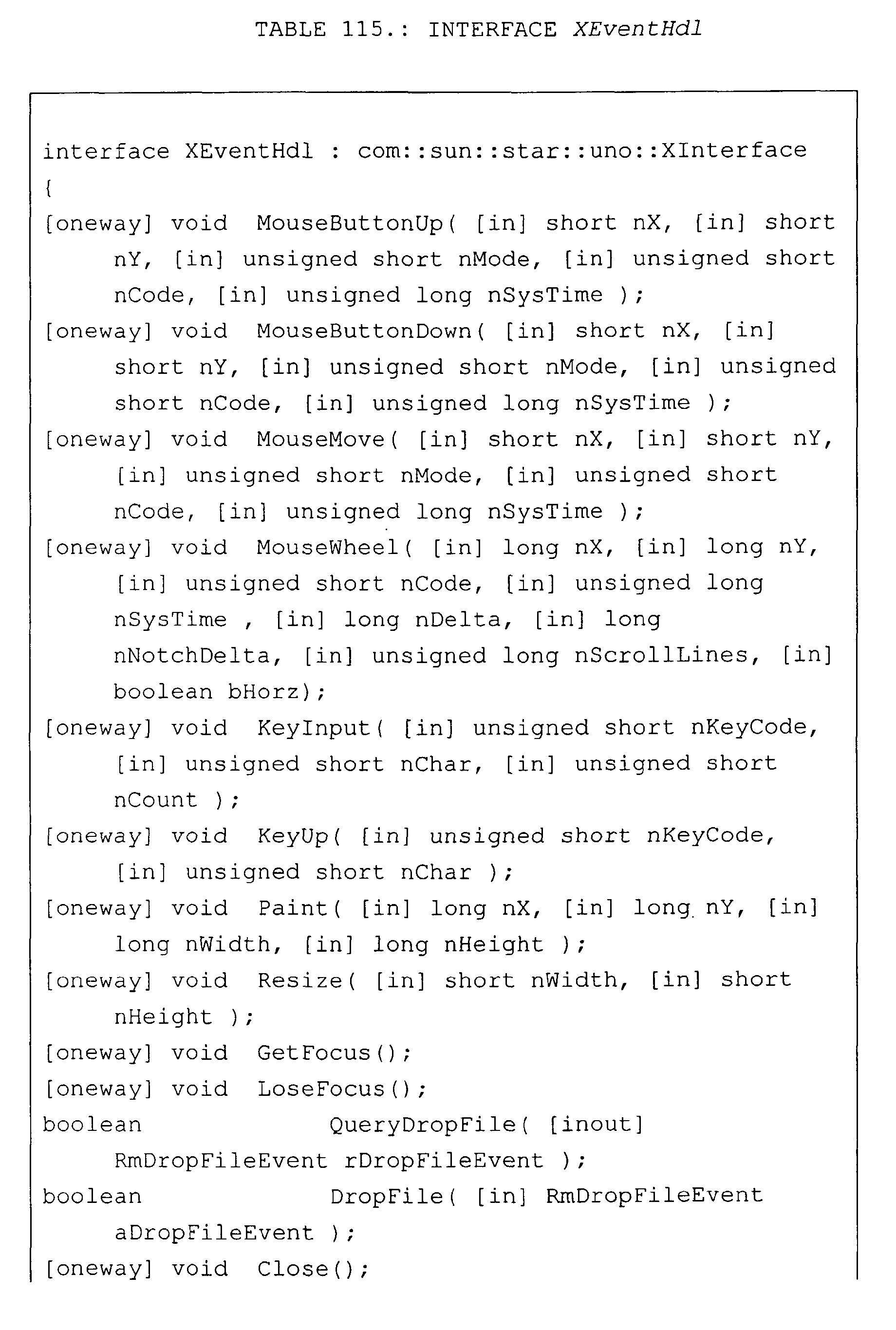


Structures used in interface XRmFrameWindow
(Table 1 and Fig. 7) include structure
RmFrameResolutions (Table 6) and structure
IDLKeyNameInfo (Table 7).


As illustrated in Fig. 6, class RmFrameWindow
includes remote output device interface XRmOutputDevice
(Table 8). Interface XRmOutputDevice inherits from
interface XInterface (Table 2), and uses structures
IDLFontMetricData, KernPair, IDLFontData, IDLFont
(Table 9). In the embodiment of Table 8, interface
XRmOutputDevice includes methods
QuerySvOutputDevicePtr, SetClipRegion, ResetClipRegion,
GetResolution, GetCharWidth, GetFontMetric,
GetKernPairs, GetDevFontList, AddFontAtom,
GetGlyphBoundRect, GetGlyphOutline, GetPixel,
GetPixelArray, SetFont, SetTextColor, SetLineColor,
SetFillColor, SetRasterOp, CopyArea, CopyBits, Invert,
InvertPolygon, InvertTracking, InvertTrackingPolygon,
DrawPixel, DrawColoredPixel, DrawPixelArray, DrawLine,
DrawRect, DrawPolyLine, DrawPolygon, DrawPolyPolygon,
DrawEllipse, DrawArc, DrawPie, DrawCord, DrawGradient,
DrawPolyPolyGradient, DrawPolyPolyHatch, DrawText,
DrawTextArray, DrawWaveLine, DrawGrid,
DrawPolyPolyTransparent, and Draw2ColorFrame.


In one embodiment, method GetFontMetric (Table 8) gets
the general metrics of the current font. If the value
of inputs nFirstChar and nLastChar are not equal,
member maCharWidths of output structure
IDLFontMetricData (Table 9) is filled as it would be in
a call by method GetCharWidth and so saves one
synchronous call. If the Boolean input value of
variable bGetKernPairs is true, member maKerningPairs
of output structure IDLFontMetricData is filled as it
would be in a call to method GetKernPairs, and this
saves another synchronous call.
In method AddFontAtom, Type is a FontAtomType; Name is
the new atom string; and Atom the new atomic value
In Table 9, a brief description of given of the values
in the various structures.


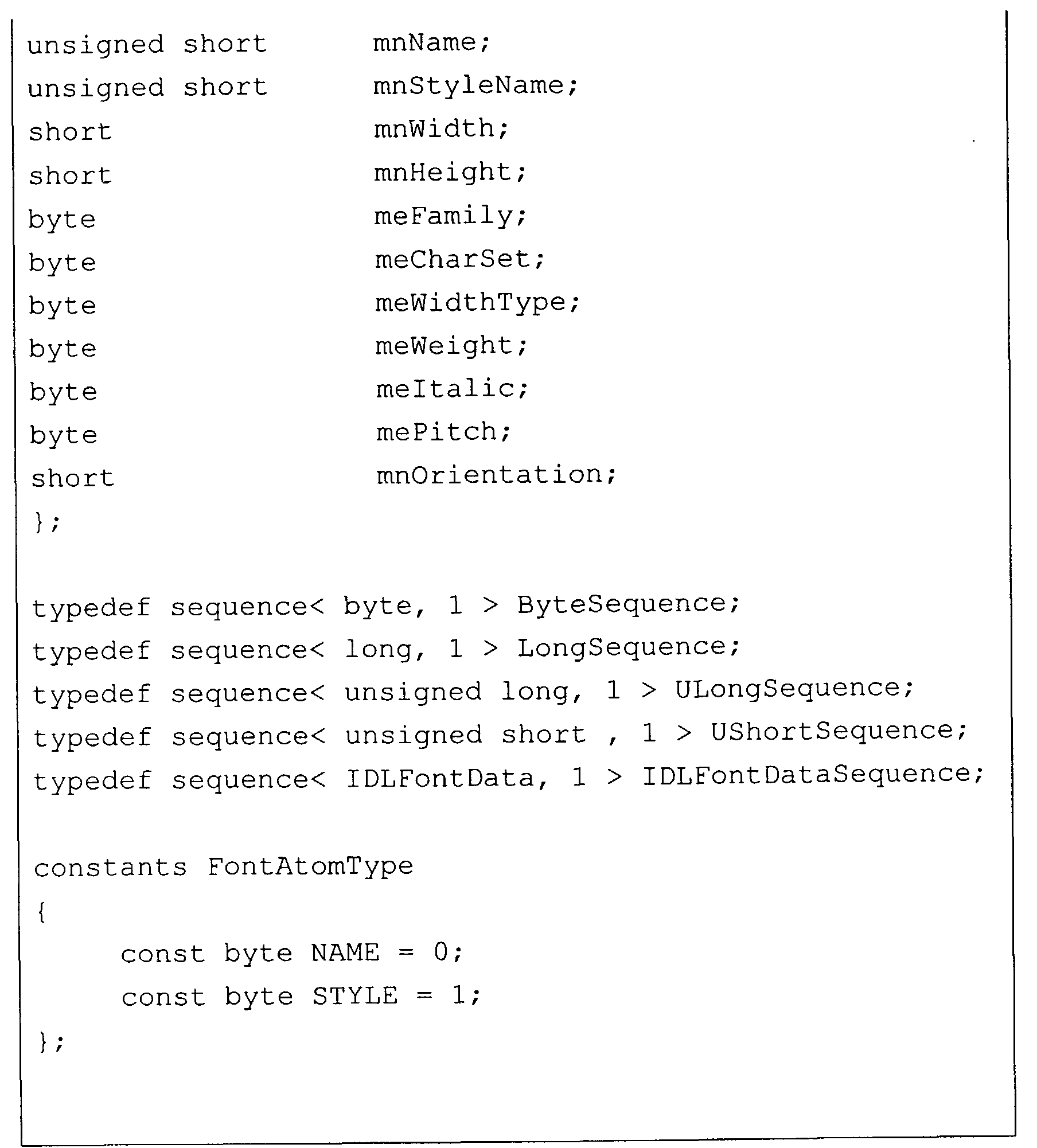
In Figure 6, class ClientFactory includes
interface XMultiInstanceFactory (Table 10 and Fig. 7).
Class ClientFactory is called by an object BeanFrame to
generate multiple instances of class RmFrameWindow.
Interface XMultiInstanceFactory inherits from interface
XInterface (Table 2).

In Figure 6, class ServiceFactory include
interface XMultiServiceFactory (Table 11 and Fig. 7).
Class ServiceFactory is called by an object connector
to generate objects LoginService and BeanService.
Interface XMultiServiceFactory inherits from interface
XInterface (Table 2) and throws an exception Exception
(Table 12).


The service factory objects support this interface for
creating components by a specifying string, i.e. the
service name. In the embodiment of Table 11, interface
XMultiServiceFactory includes methods createInstance,
createInstanceWithArguments, and
getAvailableServiceNames.
Method createInstance creates an instance of a
component which supports the services specified by the
factory. Input parameter ServiceSpecifier is a service
name that specifies the service that should be created
by this factory.
Method createInstanceWithArguments creates an instance
of a component which supports the services specified by
the factory. Input parameter aArguments is the values
of the arguments that depend on the service
specification of the factory. Normally the factory
delegates the arguments to the method init() of the
created instance. The factory is explicitly allowed to
modify, delete or add arguments. The conversion rules
of the arguments are specified by a converter service.
Input parameter ServiceSpecifier is a service name that
specifies the service that should be created by this
factory.
Method getAvailableServiceNames returns a sequence of
all service identifiers, which can be instantiated.
Table 12 presents one embodiment of exception Exception
that is used by interface XMultiServiceFactory.

In this embodiment, exception Exception is the basic
exception from which all other exceptions are derived.
Parameter Message specifies a detailed message of the
exception or an empty string if the callee does not
describe the exception. Context is an object that
describes the reason for the exception. Object Context
may be NULL if the callee does not describe the
exception.
Service LoginService that is instantiated by object
ServiceFactory of the daemon includes an interface
XLogin (Table 13 and Fig. 7). Interface XLogin
inherits from interface XInterface and uses an
enumeration ResultofLogin.


In the embodiment of Table 13, interface XLogin
includes methods installationHasBeenCompleted,
completelnstallation, login, and
getQualifiedNameOfUser.
Class BeanService includes an interface XRmStarOffice
in the embodiment of Figure 6. One embodiment of
interface XRmStarOffice is presented in Table 14.
Interface XRmStarOffice inherits from interface
XInterface and uses interfaces XMultiServiceFactory
(Table 11) and XRmFrameWindow (Table 1). See Figure 7.


In the embodiment of Table 14, interface XRmStarOffice
includes methods Start, SetUserInfoForPrinting,
AddRemotePrinter, and CreateBeanWindow. Method start
receives as input a reference to object ClientFactory,
a user name, a password, identification of a file
server, and a specification of the application that is
to be started, e.g., parameters application name,
application parameters, application language, and
version. Method CreateBeanWindow receives a reference
to object RmFrameWindow, and object ClientFactory as
inputs.
Class BeanFrame (Fig. 6) includes two interfaces,
interface XFrame (Table 15) and interface
XDispatchProvider (Table 62 and Fig. 9). In the
embodiment of Table 15, interface XFrame inherits from
interface XComponent (Table 16). Interface XFrame uses
interfaces XWindow (Table 19), XController (Table 53
and Fig. 8C), and XFrameActionListener (Table 59 and
Fig. 8C). As illustrated in Figures 8A to 8C, each of
these interfaces uses other interfaces, structures,
exceptions, and enumerations that are described more
completely below.
In the embodiment of Table 15, interface XFrame
includes methods initialize, setCreator, getCreator,
getName, setName, findFrame, isTop, activate,
deactivate, setComponent, getComponentWindow,
getController, contextChanged, addFrameActionListener,
and removeFrameActionListener


Interface XFrame makes it possible to control a frame.
Method initialize is called to initialize the frame
within a window. Method getContainerWindow provides
access to the window of the frame. Normally this is
used as the parent window of the controller window.
Method setCreator sets the frame container that created
this frame. Only the creator is allowed to call method
setCreator. Method getCreator returns the frame
container that created this frame. Method getName
returns the programmatic name of this frame. Method
setName sets the name of the frame. Normally, the name
of the frame is set initially.
Method findFrame searches for a frame with the
specified name. Frames may contain other frames, e.g.,
a frameset, and may be contained in other frames. This
hierarchy is searched with this method. First some
special names are taken into account, i.e. "","_self",
"_top", "_active" etc., flag nSearchFlags is ignored
when comparing these names with parameter
aTargetFrameName, and further steps are controlled by
flag nSearchFlags. If allowed, the name of the frame
itself is compared with the desired one, then (again,
if allowed )the method is called for all children of
the frame. Finally, the method may be called for the
parent frame (if allowed). If no frame with the given
name is found, a new top frame is created if this is
not suppressed by a special value of flag
FrameSearchFlag. The new frame also gets the desired
name.
Method isTop determines if the frame is a top frame.
In general, a top frame is the frame which is a direct
child of a task frame or which does not have a parent.
If a frame returns for this method, all calls have to
stop the search at such a frame unless the flag
FrameSearchFlag::TASKS is set.
Method activate activates this frame and thus the
component within. At first, the frame sets itself as
the active frame of its creator by calling
FrameAction::FRAME_ACTIVATED. The component within
this frame may listen to this event to grab the focus
on activation. For simple components, this can be done
by a Frame Loader. Finally, most frames may grab the
focus to one of its windows or forward the activation
to a sub-frame.
Method deactivate is called by the creator frame when
another sub-frame is activated. At first the frame
deactivates its active sub-frame, if any, and then
broadcasts a Frame Action Event with
FrameAction::FRAME_DEACTIVATING.
Method isActive determines if the frame is active.
Method setComponent sets a new component into the
frame. Method getComponentWindow returns the current
visible component in this frame. The frame is the
owner of the window. Method getController returns the
current controller within this frame. Normally, it is
set by a frame loader.
Method contextChanged notifies the frame that the
context of the controller within this frame changed
(i.e. the selection). According to a call to this
interface, the frame calls with
FrameAction::CONTEXT_CHANGED to all listeners, which
are registered using this frame. For external
controllers, this event can be used to requery
dispatches.
Method addFrameActionListener registers an event
listener, which is called when certain things happen to
the components within this frame or within sub-frames
of this frame. For example, it is possible to
determine instantiation/destruction and
activation/deactivation of components. Method
removeFrameActionListener unregisters an event
listener, which was registered with
addFrameActionListener().
Interface XFrame inherits from interface XComponent.
One embodiment of interface XComponent is presented in
Table 16. Interface XComponent inherits from interface
XInterface (Table 2) and uses interface XEventListener
that in turn uses structure EventObject. See
Figure 8A.

Interface XComponent controls the lifetime of
components. Actually the real lifetime of an object is
controlled by references kept on interfaces of the
object. There are two distinct meanings in keeping a
reference to an interface: first is to own the object;
and second is to know the object.
To prevent cyclic references from resulting in failure
to destroy an object, references of interfaces to the
object are allowed only (i) by the owner, (ii) if the
reference is very temporary, or (iii) you are
registered as an Event Listener at that object and
cleared the reference when "disposing" is called.
An owner of an object calls method dispose to dispose
of the object. Only the owner of the object calls
method dispose if the object should be destroyed. All
objects and components must release the references to
the objects. If the object is a broadcaster, all
listeners are removed and method
XEventListener::disposing() is called on all listeners.
Due to the importance of the concept of method
XComponent::dispose(), a figurative example is
provided. Imagine there was a hole in the floor and
some people around it were holding a box (our
component). Everyone who holds the box for a longer
time than just temporarily (i.e. to put something in or
get something out) has to watch a light bulb, which is
attached to the box (listening to event
XEventListener::disposing()). Now, when the owner of
the box switched the light on (calling method
XComponent::dispose()), everybody holding the box had
to take their hands off (clear the interface handles).
If and only if everyone did that, did the box fall
(getting deleted). However, only the owner is allowed
to switch the light on! After method dispose is
called, the instance has to throw exception
DisposedException for all non-event-method calls and
event-method calls have to be ignored.
The following is an example of one embodiment.
void dispose()

Method addEventListener adds an event listener to the
listener list for the object. The broadcaster fires
the disposing method of this listener if method
dispose() is called. Conversely, method
removeEventListener removes an event listener from the
listener list for the object.
As described above, interface XComponent uses interface
XEventListener (Table 17.)


Interface XEventListener (Table 17) inherits from
interface XInterface (Table 2). Interface
XEventListener is a tagging interface that all event
listener interfaces must extend. Method disposing is
called when the broadcaster is about to be disposed.
All listeners and all other objects, which reference
the broadcaster should release the references. One
embodiment of structure EventObject is presented in
Table 18.

Structure EventObject specifies the base for all event
objects and identifies the source of the event. Field
Source refers to the object that fired the event.
As explained above, interface XWindow (Table 19) is
used by interface XFrame (Table 15). See also Fig. 8A.
In the embodiment of Table 19, interface XWindow
inherits from interface XComponent (Table 16) and uses
interfaces XWindowListener (Table 21), XFocusListener
(Table 23), XKeyListener (Table 25), XMouseListener
(Table 28), XMouseMotionListener (Table 30), and
XPaintListener (Table 31), and structure Rectangle
(Table 20), each of which is described herein.


Interface XWindow (Table 19) specifies the basic
operations for a window component. A window is a
rectangular region on an output device with a position,
size, and internal coordinate system. The main sense
of a window is to receive events from the user.
Method setPosSize sets the outer bounds of the window.
Method getPosSize returns the outer bounds of the
window. Method setVisible shows or hides the window
depending on the parameter. Method setEnable enables
or disables the window depending on the parameter.
Method setFocus sets the focus to the window. Method
addWindowListener adds the specified component listener
to receive component events from this window component.
Method removeWindowListener removes the specified
listener so it no longer receives component events from
this window component. Method addFocusListener adds
the specified focus listener to receive focus events
from this window component. Method removeFocusListener
removes the specified focus listener so it no longer
receives focus events from this component. Method
addKeyListener adds the specified key listener to
receive key events from this component. Method
removeKeyListener removes the specified key listener so
it no longer receives key events from this component.
Method addMouseListener adds the specified mouse
listener to receive mouse events from this component.
Method removeMouseListener removes the specified mouse
listener so it no longer receives mouse events from
this component. Method addMouseMotionListener adds the
specified mouse motion listener to receive mouse motion
events from this component. Method
removeMouseMotionListener removes the specified mouse
motion listener so it no longer receives mouse motion
events from this component. Method addPaintListener
adds the specified paint listener to receive paint
events from this component. Method removePaintListener
removes the specified paint listener so it no longer
receives paint events from this component.
Structure Rectangle (Table 20) specifies a rectangular
area by position and size. Field Y specifies the y-coordinate.
Field Width specifies the width. Field
Height specifies the height.

An embodiment of interface XWindowListener that is used
in the above embodiment of interface XWindow (Table 19)
is presented in Table 21. Interface XWindowListener
inherits from interface XEventListener (Table 17) and
uses structure WindowEvent (Table 22.)

Interface XWindowListener makes it possible to receive
window events. Component events are provided only for
notification purposes. Moves and resizes are handled
internally by the window component, so that the GUI
layout works properly independent of whether a program
registers such a listener. Method windowResized is
invoked when the window has been resized. Method
windowMoved is invoked when the window has been moved.
Method windowShown is invoked when the window has been
shown. Method windowHidden is invoked when the window
has been hidden.
One embodiment of structure WindowEvent used in
Table 21 is presented in Table 22.

Structure WindowEvent specifies the component-level
keyboard event and inherits from structure EventObject
(Table 18). Field X specifies the outer X-position of
the window. Field Y specifies the outer Y-position of
the window. Field Width specifies the outer (total)
width of the window. Field Height specifies the outer
(total) height of the window. Field LeftInset
specifies the inset from the left. The inset is the
distance between the outer and the inner window, in
other words in this case it is the width of the left
border. Field TopInset specifies the inset from the
top. The inset is the distance between the outer and
the inner window, in other words in this case it is the
height of the top border. Field RightInset specifies
the inset from the right. The inset is the distance
between the outer and the inner window, in other words
in this case it is the width of the right border.
Field BottomInset specifies the inset from the bottom.
The inset is the distance between the outer and the
inner window, in other words in this case it is the
height of the bottom border.
An embodiment of interface XFocusListener that is used
in the above embodiment of interface XWindow (Table 19)
is presented in Table 23. Interface XFocusListener
inherits from interface XEventListener (Table 17) and
uses structure FocusEvent (Table 24.)

Interface XFocusListener makes it possible to receive
keyboard focus events. The window, which has the
keyboard focus, is the window, which gets the keyboard
events. Method focusGained is invoked when a window
gains the keyboard focus. Method focusLost is invoked
when a window loses the keyboard focus.
One embodiment of structure FocusEvent used in Table 23
is presented in Table 24.
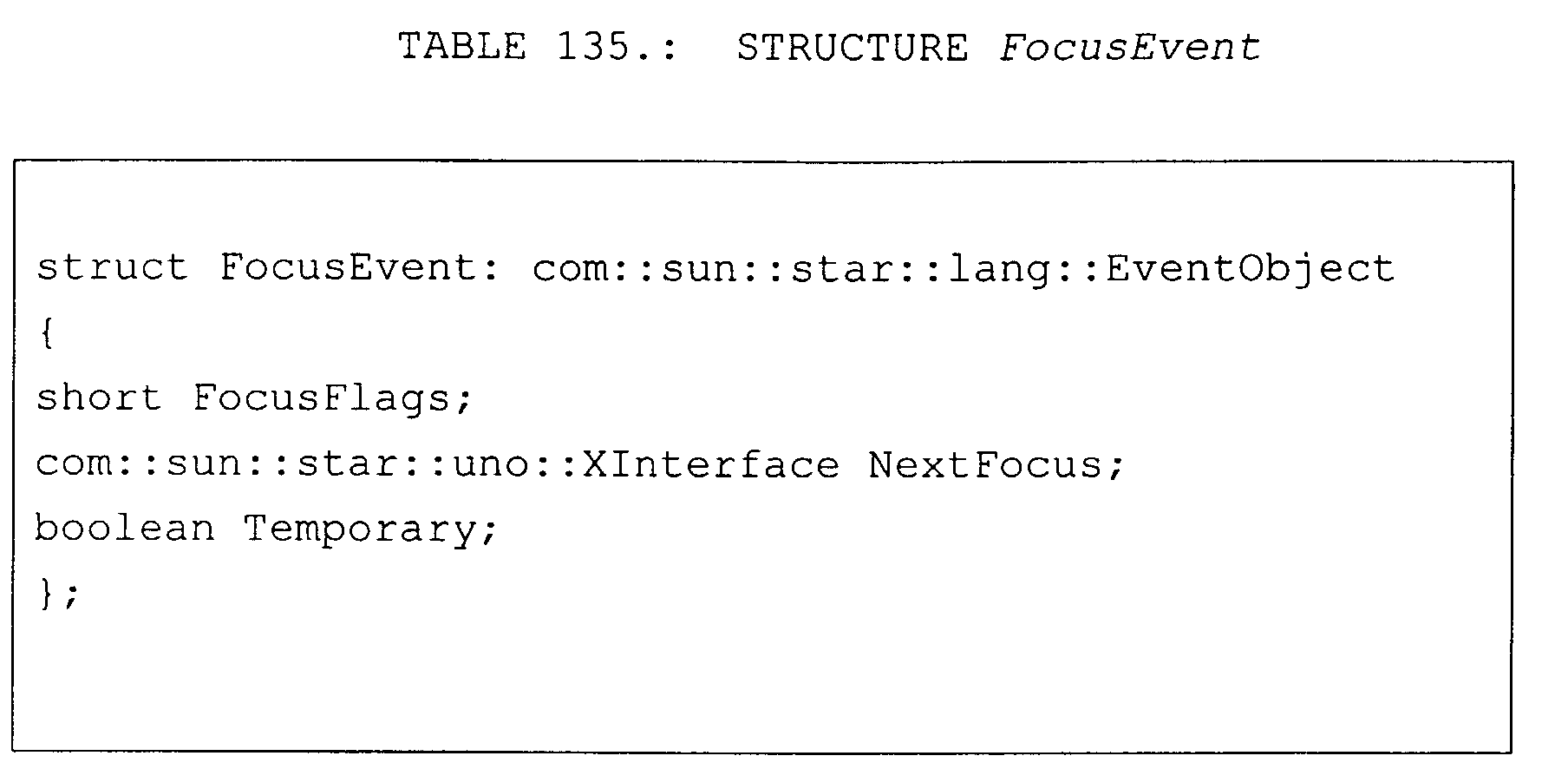
Structure FocusEvent specifies a keyboard focus event,
and inherits from structure EventObject (Table 18).
There are two levels of focus change events: permanent
and temporary. Permanent focus change events occur
when focus is directly moved from one component to
another, such as through calls to method requestFocus()
or as the user uses the Tab key to traverse components.
Temporary focus change events occur when focus is
gained or lost for a component as the indirect result
of another operation, such as window deactivation or a
scrollbar drag. In this case, the original focus state
is automatically restored once that operation is
finished, or for the case of window deactivation, when
the window is reactivated. Both permanent and
temporary focus events are delivered using the
FOCUS_GAINED and FOCUS_LOST event ids; the levels may
be distinguished in the event using the method
isTemporary()
Field FocusFlags specifies the reason for the focus
change as an arithmetic, or combination of
FocusChangeReason. Field NextFocus contains the window
which gets the focus on a lose focus event. Field
Temporary specifies if this focus change event is a
temporary change.
An embodiment of interface XKeyListener that is used in
the above embodiment of interface XWindow (Table 19) is
presented in Table 25. Interface XKeyListener inherits
from interface XEventListener (Table 17) and uses
structure KeyEvent (Table 24.) that in turn inherits
from structure InputEvent (Table 27).

Interface XKeyListener makes it possible to receive
keyboard events. Method keyPressed is invoked when a
key has been pressed. Method keyReleased is invoked
when a key has been released.
The embodiment of structure KeyEvent in Table 26
inherits from structure InputEvent (Table 27), as
described above. Structure KeyEvent specifies the
component-level keyboard event. Field KeyCode contains
the integer code representing the key of the event.
This is a constant from the constant group Key. Field
KeyChar contains the Unicode character generated by
this event or 0. Field KeyFunc contains the function
type of the key event. This is a constant from the
constant group KeyFunction.

Structure InputEvent is the root event class for all
component-level input events and inherits from
structure EventObject (Table 18). Input events are
delivered to listeners before they are processed
normally by the source where they originated.
Structure InputEvent contains the modifier keys, which
were pressed while the event occurred, i.e., zero or
more constants from the KeyModifier group.


An embodiment of interface XMouseListener that is used
in the above embodiment of interface XWindow (Table 19)
is presented in Table 28. Interface XMouseListener
inherits from interface XEventListener (Table 17) and
uses structure MouseEvent (Table 29.) that in turn
inherits from structure InputEvent (Table 27).

Interface XMouseListener makes it possible to receive
events from the mouse in a certain window. Method
mousePressed is invoked when a mouse button has been
pressed on a window. Method mouseReleased is invoked
when a mouse button has been released on a window.
Method mouseEntered is invoked when the mouse enters a
window. Method mouseExited is invoked when the mouse
exits a window.
The embodiment of structure MouseEvent in Table 29
inherits from structure InputEvent (Table 27).

Structure MouseEvent specifies an event from the mouse.
Field Buttons contains the pressed mouse buttons, which
are zero or more constants from the group MouseButton.
Field X contains the x coordinate location of the
mouse. Field Y contains the y coordinate location of
the mouse. Field ClickCount contains the number of
mouse clicks associated with event. Field PopupTrigger
specifies if this event is a popup-menu trigger event.
An embodiment of interface XMouseMotionListener that is
used in the above embodiment of interface XWindow
(Table 19) is presented in Table 30. Interface
XMouseMotionListener inherits from interface
XEventListener (Table 17) and uses structure MouseEvent
(Table 29).

Interface XMouseMotionListener makes it possible to
receive mouse motion events on a window. Method
mouseDragged is invoked when a mouse button is pressed
on a window and then dragged. Mouse drag events
continue to be delivered to the window where the first
event originated until the mouse button is released
independent of whether the mouse position is within the
bounds of the window. Method MouseMoved is invoked
when the mouse button has been moved on a window with
no buttons down.
An embodiment of interface XPaintListener that is used
in the above embodiment of interface XWindow (Table 19)
is presented in Table 31. Interface XPaintListener
inherits from interface XEventListener (Table 17) and
uses structure PaintEvent (Table 32) that inherits from
structure EventObject (Table 18) and structure
Rectangle (Table 20). See Figure 8B.

Interface XPaintListener makes it possible to receive
paint events. Method WindowPaint is called when a
region of the window becomes invalid, for example,
because another window was moved away.

Structure PaintEvent specifies the paint event for a
component. This event is a special type, which is used
to ensure that paint/update method calls are serialized
along with the other events delivered from the event
queue. Field UpdateRect contains the rectangle area,
which needs to be repainted. Field Count contains the
number of paint events that follows this event if it is
a multiple PaintEvent. Paint events can be collected
until Count is zero.
An embodiment of interface XFramesSupplier that is used
in the above embodiment of interface XWindow (Table 19)
is presented in Table 33. Interface XFramesSupplier
inherits from interface XFrame (Table 15) and uses
interface XFrames that in turn inherits from several
other interfaces as illustrated in Figure 8B, and uses
several structures, enumerations, and exceptions. One
embodiment of each of these interfaces, structures,
enumeration, and exceptions are described herein.

Method getFrames returns the collection of (sub-)
frames, which is represented by a container
FramesContainer. Method getActiveFrame returns the
sub-frame, which is active within this frame. This may
be the frame itself. The active frame is defined as
the frame, which contains (recursively) the window with
the focus. If no window within the frame contains the
focus, this method returns the last frame, which had
the focus. If no containing window ever had the focus,
the first frame within this frame is returned.
Method setActive Frame is called on activation of a
direct sub-frame. This method is allowed to be called
only by a sub-frame. After this call, the frame
specified by input parameter xFrame is returned. In
general this method first calls the method at the
creator frame with this as the current argument. Then
it broadcasts the FrameActionEvent
FrameAction::FRAME_ACTIVATED.
In the embodiment of Table 34, interface XFrames
inherits from interface XIndexAccess (Table 35).
Interface XFrames manages and creates frames. Frames
may contain other frames by implementing an interface
XFrames and may be contained in other frames.

Method append appends the specified Frame to a list of
sub-frames. Method queryFrames returns all child
frames of the container, which are intended to be
visible to other objects. The content of the sequence
may be limited by the caller through the flag
FrameSearchFlag.
Method remove removes the frame from its container.
The creator attribute of the frame must be reset by the
caller of this method.
The embodiment of interface XIndexAccess in Table 35
provides access to the elements of a collection through
an index. This interface should only be used if the
data structure itself is indexed.

Method getCount returns the number of elements. Method
getByIndex returns the element at the specified index.
Parameter Index specifies the position in the array.
The first index is 0. Method getByIndex throws
com::sun::star::lang::IndexOutOfBoundsException
(Table 52) if the index is not valid. Method
getByIndex throws
com::sun::star::lang::WrappedTargetException (Table 49), if the implementation has internal reasons for exceptions that are wrapped in exception WrappedTargetException.
com::sun::star::lang::WrappedTargetException (Table 49), if the implementation has internal reasons for exceptions that are wrapped in exception WrappedTargetException.
In this embodiment, interface XElementAccess is the
base interface of all collection interfaces.

Interface XElementAccess inherits from interface
XInterface (Table 2). Method getElementType returns
the type of the elements. Void means that the
container is a multi-type container and the exact
types with this interface cannot be determined with
this method. Method hasElements returns <TRUE> if the
object contain elements, otherwise <FALSE>.
One embodiment of interface XIdlClass is presented in
Table 37. Interface XIdlClass provides information
about a type or module. Every array also belongs to a
type that is reflected as an XIdlClass object that is
shared by all arrays with the same element type and
number of dimensions. Finally, any of the primitive IDL
types are also represented as XIdlClass objects. This
includes "void, any, boolean, char, float, double,
octet, short, long, hyper, unsigned octet, unsigned
short, unsigned long" and "unsigned hyper". Interface
XIdlClass inherits from interface XInterface (Table 2)

Method getClasses returns all types and modules, which
are declared in this class. Method getClass returns a
type or module with the given name that is declared in
this class. Method equals returns <TRUE> if the
instances describe the same type, otherwise <FALSE>.
Method isAssignableFrom tests if the parameter xType is
a subclass of this class. Method getTypeClass returns
the type that this instance represents. Method getName
returns the fully qualified name of the type of object
(class, interface, array, sequence, struct, union, enum
or primitive) represented by this XIdlClass object.
Method getUik returns the UIK from this type. If the
type has no UIK, the returned UIK is zero.
If this object represents an interface or a class, the
objects that represent the superclasses or
superinterfaces of that class are returned by method
getSuperclasses. If this object is the one that
represents the topmost class or interface, an empty
sequence is returned.
Method getInterfaces determines the interfaces
implemented by the class or interface represented by
this object. If the class or interface implements no
interfaces, the method returns a sequence of length 0.
If this class represents an array or sequence type,
method GetComponentType returns the XIdlClass object
representing the component type of the array or
sequence; otherwise it returns null. Method getField
returns an XIdlField object that reflects the specified
member field of the class, interface, struct, union,
enum or exception represented by this XIdlClass object.
If a field with the specified name is not found, 0 is
returned. The field to be reflected is located by
searching all the member fields of the class,
interface, struct, union, enum or exception represented
by this XIdlClass object for a field with the specified
name or for NULL, if a field with the specified name is
not found. Parameter aName specifies the simple name
of the desired field.
Method getFields returns a sequence containing Field
objects reflecting all the accessible fields of the
class, interface, struct, union or enum represented by
this XIdlClass object. Method getFields returns a
sequence of length 0 if the class or interface has no
accessible fields, or if it represents an array, a
sequence or a primitive type. Specifically, if this
XIdlClass object represents a class, this method
returns the fields of this class and of all its
superclasses. If this XIdlClass object represents an
interface, the method returns the fields of this
interface and of all its superinterfaces. If this
XIdlClass object represents an array, sequence or
primitive type, this method returns a sequence of
length 0.
Method getMethod returns an XIdlMethod object that
reflects the specified member method of the interface
represented by this XIdlClass object. If a method with
the specified name is not found, "0" is returned. The
method to be reflected is located by searching all the
member methods of the interface represented by this
XIdlClass object for a method with the specified name.
Parameter aName specifies the simple name of the
desired method.
Method getMethods returns a sequence containing
XIdlMethod objects reflecting all the member methods of
the class or interface represented by this XIdlClass
object, including those declared by the class or
interface and those inherited from superclasses and
superinterfaces. Returns a sequence of length 0 if the
class or interface has no member methods.
Method getArray returns interface XIdlArray (Table 50)
to get and set the elements by index if the represented
type is an array or sequence. Method createObject
creates an instance of the type represented by this
XIdlClass object if the represented type is a basic
type, struct, enum, or sequence.
Enumeration TypeClass (Table 38) describe all type
classes, which can be defined in the IDL.


Interface XIdlField (Table 39) inherits from
interface XIdlMember (Table 40).

Method getType returns an XIdlClass object that
identifies the declared type for the field represented
by this XIdlField object. Method getAccessMode returns
an enumeration value, which denotes whether the field
is "const", "readonly", "writeonly" or "readwrite".
Method get returns the value of the field represented
by this field on the specified object. The underlying
field's value is obtained as follows:
If the underlying field is a constant, the object argument is ignored; it may be NULL;
If the underlying field is a constant, the object argument is ignored; it may be NULL;
Otherwise, the underlying field is an instance field.
If the specified object argument is NULL, the method
throws an "IllegalArgumentException". If the specified
object is not an instance of the class, interface,
struct, union or enum declaring the underlying field,
the method throws an "IllegalArgumentException".
Otherwise, the value is retrieved from the underlying
instance or constant.
Method set sets the field represented by this XIdlField
object on the specified object argument to the
specified new value. The operation proceeds as follows.
If the specified object argument is NULL, the method
throws an exception IllegalArgumentException
(Table 42). If the specified object argument is not an
instance of the class or interface declaring the
underlying field, the method throws an exception
IllegalArgumentException. If the underlying field is
constant, the method throws an exception
IllegalAccessException (Table 43). If the new value
cannot be converted to the type of underlying field by
an identity or widening conversion, the method throws
an IllegalArgumentException. The field is set to the
possibly widened new value.
Interface XIdlMember (Table 40) inherits from interface
XInterface (Table 2). Interface XIdlMember makes it
possible to access members of classes dynamically.

Method getDeclaringClass returns the XIdlClass object
representing the class, interface, struct, union or
enum that declares the member represented by this
member. Method getName returns the fully qualified
name of the type (class, interface, array, sequence,
struct, union, enum or primitive) represented by this
XIdlClass object, as a string.
The values in enumeration FieldAccessMode (Table 41)
are used to specify the kind of attribute or property.


Exception IllegalArgumentException (Table 42) is thrown
to indicate that a method has passed an illegal or
inappropriate argument. Exception
IllegalArgumentException inherits from exception
Exception (Table 12). Field ArgumentPosition
identifies the position of the illegal argument. This
field is -1 if the position is not known.


Exception IllegalAccessException (Table 43) is thrown
when an application tries to change a constant
property. Exception IllegalAccessException inherits
from exception Exception (Table 12).

Interface XIdlMethod (Table 44) inherits from interface
XIdlMember (Table 40). Interface XIdlMember makes it
possible to access the specification of a method
dynamically.


Method getReturnType returns an XIdlClass object that
represents the formal return type of the method
represented by this method object. Method
getParameterTypes returns a sequence of XIdlClass
objects that represent the formal parameter types, in
declaration order, of the method represented by this
Method object. Method getParameterTypes returns a
sequence of length 0 if the underlying method takes no
parameters.
Method getParameterInfos returns a sequence of
ParamInfo objects that represent all information about
the formal parameter types, in declaration order, of
the method represented by this Method object. Method
getParameterInfos returns a sequence of length 0 if the
underlying method takes no parameters.
Method getExceptionTypes returns a sequence of
XIdlClass objects that represent the types of the
checked exceptions thrown by the underlying method
represented by this Method object. Method
getExceptionTypes returns a sequence of length 0 if the
method throws no checked exceptions.
Method getMode returns an enumeration value, which
denotes whether the method is one-way or two-way.
Method invoke invokes the underlying method represented
by this method object on the specified object with the
specified parameters. Individual parameters are
subject to widening conversions as necessary.
Method invocation proceeds in the following order:
If the specified object argument is NULL, the invocation throws an IllegalArgumentException; and
If the specified object argument is NULL, the invocation throws an IllegalArgumentException; and
Otherwise, if the specified object argument is not an
instance of the class or interface declaring the
underlying method, the invocation throws an exception
IllegalArgumentException (Table 42).
If the number of actual parameters supplied via args is
different from the number of formal parameters required
by the underlying method, the invocation throws an
Exception IllegalArgumentException. For each actual
parameter in the supplied args array, if the parameter
value cannot be converted to the corresponding formal
parameter type by an identity or widening conversion,
the invocation throws exception
IllegalArgumentException. When the control transfers
to the underlying method and the method stops abruptly
by throwing an exception, the exception is placed in an
exception InvocationTargetException (Table 48) and
thrown in turn to the caller of the method. If the
method completes normally, the value it returns is
returned to the caller of the method. If the
underlying method returns type is void, the invocation
returns VOID.
Structure ParamInfo (Table 45) describes a formal
parameter of a method.

The values in Enumeration ParamMode (Table 46) are used
to specify if a formal parameter of a method is used
for input, output or both. If the value is an IN
parameter, data can only transferred from the callee to
the caller. If the value is an OUT parameter, data can
only transferred from the caller to the callee. If
value is an INOUT parameter, data can transferred in
both directions.

The values in Enumeration MethodMode (Table 47) are
used to specify the calling mode of a method. If the
value is an ONEWAY parameter, the method call may be
asynchronous. If the value is a TWOWAY parameter, the
method call is synchronous.

Exception InvocationTargetException (Table 48) is a
checked exception that wraps another exception.
Typically such exceptions are thrown by an invoked
method or constructor. Exception
InvocationTargetException inherits from exception
WrappedTargetException (Table 49).

Exception WrappedTargetException (Table 49) is a
checked exception that wraps an exception thrown by the
original target. Normally this exception is declared
for generic methods. Exception WrappedTargetException
inherits from exception Exception(Table 12).

Interface XIdlArray (Table 50) provides methods to
dynamically access arrays. Interface XIdlArray
inherits from interface XInterface (Table 2).

Method realloc in interface XIdlArray changes the size
of the array to the new size. If the new length is
greater, the additional elements are default
constructed, otherwise the elements are destructed.
Method realloc throws an exception
IllegalArgumentException (Table 42) if the specified
object is not an array or if the specified object is
null.
Method getLen in interface XIdlArray returns the number
of elements in the array. Method getLen throws an
exception IllegalArgumentException (Table 42) if the
specified object is not an array or if the specified
object is null.
Method get in interface XIdlArray returns the value of
the indexed component in the specified array object.
Method get throws exception IllegalArgumentException,
if the specified object is not an array or if the
specified object is null. Method get throws exception
ArrayIndexOutOfBoundsException (Table 51), if the
specified index argument is negative, or if the
specified index argument is greater than or equal to
the length of the specified array.
Method set in interface XIdlArray sets the value of the
indexed component of the specified array object to the
specified new value. Method set throws exception
IllegalArgumentException, if the specified object is
not an array or if the specified object is null.
Method set throws exception
ArrayIndexOutOfBoundsException (Table 51), if the
specified index argument is negative, or if the
specified index argument is greater than or equal to
the length of the specified array.
Exception ArrayIndexOutOfBoundsException (Table 51) is
thrown to indicate that an array has been accessed with
an illegal index. The index is either negative or
greater than or equal to the size of the array.
Exception ArrayIndexOutOfBoundsException inherits from
exception IndexOutOfBoundsException (Table 52).

Exception IndexOutOfBoundsException (Table 52) is
thrown to indicate that a container has been accessed
with an illegal index. The index is either negative or
greater than or equal to the count of the elements.
Exception IndexOutOfBoundsException inherits from
exception Exception (Table 12).

As explained above, interface XFrame (Table 15) uses
interface XController (Table 53). With interface
XController, components viewed in a frame can serve
events by supplying dispatches. Interface XController
inherits from interface XComponent (Table 16).

Method attachFrame (Table 53) is called to attach the
controller with its managing frame. Method attachModel
is called to attach the controller to a new model.
Method suspend is called to prepare the controller for
closing the view. Method getViewData returns data that
can be used to restore the current view status. Method
restoreViewData restores the view status using the data
gotten from a previous call. Method getModel returns
the currently attached model. Method getFrame returns
the frame containing this controller.
In Table 54, interface XModel represents a component,
which is created from an URL and arguments. Interface
XModel is a representation of a resource in the sense
that the interface was created/loaded from the
resource. The arguments are passed to the loader to
modify its behavior. An example for such an argument
is "AsTemplate", which loads the resource as a template
for a new document. Models can be controlled by
controller components, which are usually views of the
model. If there is at least one controller, there is
by definition a current controller, and if that
controller supports interface XSelectionSupplier, it
has a current selection too. Interface XModel inherits
from interface XComponent (Table 16).


Method attachResource (Table 54) informs a model about
its resource description. Method getURL returns the
URL of the resource, which is represented by this
model. Method getArgs returns the arguments with which
the model was originally created or stored the last
time. Method connectController is called whenever a
new controller is created for this model. Interface
XComponent of the controller must be used to recognize
when the controller is deleted. Method
disconnectController is called whenever a new
controller is created for this model. Again, interface
XComponent of the controller must be used to recognize
when the controller is deleted.
Method lockControllers (Table 54) suspends some
notifications to the controllers, which are used for
display updates. The calls to this method may be
nested and even overlapping, but the calls must be in
pairs. While there is at least one lock remaining,
some notifications for display updates are not
broadcasted.
Method unlockControllers (Table 54) resumes the
notifications, which were suspended by call to
lockControllers. The calls to this method may be
nested and even overlapping, but they must be in pairs.
While there is at least one lock remaining, some
notifications for display updates are not broadcasted.
Method hasControllersLocked (Table 54) determines if
there is at least one lock remaining. While there is
at least one lock remaining, some notifications for
display updates are not broadcasted to the controllers.
Method getCurrentController (Table 54) returns the
controller, which currently controls this model. If
the controller, which is active, is a controller of
this model, it will be returned. If not, the
controller, which was the last active controller of
this model, is returned. If no controller of this
model ever was active, the controller first registered
is returned. If no controller is registered for this
model, NULL is returned.
Method setCurrentController (Table 54) sets a
registered controller as the current controller.
Method setCurrentController throws exception
NoSuchElementException (Table 58).
Method getCurrentSelection (Table 54) returns the
current selection in the current controller. If there
is no current controller, the method returns NULL.
Structure PropertyValue (Table 55) specifies a property
value. Field Name (Table 55) specifies the name of the
property. The name is unique within a sequence of
PropertyValues. Field Handle (Table 55) contains an
implementation-specific handle for the property. The
handle may be -1 if the implementation has no handle.
If available, the handle it can be used for fast
lookups. Field Value contains the value of the
property or void if no value is available. Field State
determines if the value comes from the object itself or
from a default, and if the value cannot be determined
exactly

Enumeration PropertyState (Table 56) lists the states
that a property value can have. The state consists of
two aspects: whether a value is available or void; and
whether the value is stored in the property set itself
or is a default or ambiguous.
Value DIRECT_VALUE (Table 56) of the property is stored
in the PropertySet itself. The property value must be
available and of the specified type. If field
PropertyAttribute in structure Property (Table 57)
contains PropertyAttribute::MAYBEVOID, then the value
may be void.
Value DEFAULT_VALUE (Table 56) of the property is
available from a master (e.g. template). Field
PropertyAttribute in structure Property (Table 57) must
contain the flag PropertyAttribute::MAYBEDEFAULT. The
property value must be available and of the specified
type. If field PropertyAttribute in the structure
Property contains PropertyAttribute::MAYBEVOID, the
value may be void.
Value AMBIGUOUS_VALUE (Table 56) of the property is
only a recommendation because there are multiple values
for this property (e.g. from a multi selection). Field
PropertyAttribute in structure Property (Table 57) must
contain flag PropertyAttribute::MAYBEAMBIGUOUS. The
property value must be available and of the specified
type. If field Attribute in structure Property
contains PropertyAttribute::MAYBEVOID, n the value may
be void.

Structure Property (Table 57) describes a property.
There are three types of properties: bound properties,
constrained properties and free properties. Field Name
specifies the name of the property. The name is unique
within an XPropertySet. Field Handle contains an
implementation specific handle for the property. The
handle may be -1 if the implementation has no handle.
Field Type contains an object that identifies the
declared type for the property. If the property has
multiple types or the type is not known, but not any,
void must be returned. Field Attributes may contain
zero or more constants of the PropertyAttribute
constants group.

Exception NoSuchElementException (Table 58) is thrown
by the method to indicate that there are no more
elements in the enumeration. Exception
NoSuchElementException inherits from exception
Exception (Table 12).

As explained above, interface XFrame (Table 15) uses
interface XFrameActionListener (Table 59). Interface
XFrameActionListener has to be provided if an object
wants to receive events when several things happen to
components within frames of the desktop, e.g., events
of instantiation/destruction and
activation/deactivation of components can be received.
Interface XFrameActionListener inherits from interface
XEventListener (Table 17). Method frameAction is
called whenever any action occurs to a component within
a frame.

Event structure FrameActionEvent (Table 60) is
broadcast for action, which can happen to components
within frames. Event structure FrameActionEvent
inherits from structure EventObject (Table 18).
In Table 60, field Frame contains the frame in which
the event occurred. Field Action specifies the
concrete event.

Enumeration FrameAction (Table 61) specifies the
events, which can happen to components in frames. An
event COMPONENT_ATTACHED is broadcast whenever a
component is attached to a frame. This is almost the
same as the instantiation of the component within that
frame. The component is attached to the frame
immediately before this event is broadcast. An event
COMPONENT_DETACHING is broadcast whenever a component
is detaching from a frame. This is quite the same as
the destruction of the component, which was in that
frame. At the moment when the event is broadcast the
component is still attached to the frame but in the
next moment it is not attached. An event
COMPONENT_REATTACHED is broadcast whenever a component
is attached to a new model. In this case the component
remains the same but operates on a new model component.
An event FRAME_ACTIVATED is broadcast whenever a
component is activated. Activations are broadcast from
the top component, which was not active before, down to
the inner most component. An event FRAME_DEACTIVATING
broadcast immediately before the component is
deactivated. Deactivations are broadcast from the
innermost component, which does not stay active up to
the outer most component, which does not stay active.
An event CONTEXT_CHANGED is broadcast whenever a
component changed its internal context (i.e. the
selection). If the activation status within a frame
changes, this counts as a context change too. An event
FRAME_UI_ACTIVATED is broadcast by an active frame when
the active frame is getting user interface control
(tool control). An event FRAME_UI_DEACTIVATING is
broadcast by an active frame when the active frame is
losing user interface control (tool control).

As described above, interface XDispatchProvider
(Table 62 and Fig. 9) is an interface of class
BeanFrame (Fig. 6). Interface XDispatchProvider
provides Dispatch interfaces for certain functions,
which are useful at the user interface. Interface
XDispatchProvider inherits from interface XInterface
(Table 2), and uses interface XDispatch (Table 63) and
structures URL (Table 64) and DispatchDescriptor
(Table 67).

Method queryDispatch (Table 62) searches for an
XDispatch for the specified URL within the specified
target frame. Method queryDispatches returns multiple
dispatch interfaces for the specified descriptors at
once. Actually this method is redundant to method
DispatchProvider::queryDispatch to avoid multiple
remote calls.
Interface XDispatch (Table 63) serves state information
of objects, which can be connected to controllers (e.g.
toolbox controllers). Each state change is to be
broadcast to all registered status listeners. The
first notification should be performed synchronously,
if not, controllers may flicker. State listener must
be aware of this synchronous notification. The state
includes enabled/disabled and a short descriptive text
of the function (e.g. "undo insert character"). The
state is to be broadcast whenever this state changes or
the controller should reget the value for the URL to
which it is connected. Additionally, a context-switch-event
is to be broadcast whenever the object may be out
of scope to force the state listener to requery the
XDispatch. Interface XDispatch inherits from interface
XInterface (Table 2).

Method dispatch (Table 63) dispatches (executes) an URL
asynchronously. Method dispatch is only allowed to
dispatch URLs for which the current user gets the
dispatch. Additional arguments "'#..." or "?..." are
allowed.
The following is an example for a click-handler of a
hyperlink in a view.
XFrame xTargetFrame = m_xFrame-
&gt; findFrame (m_aHyperlink-
&gt;getTargetFrameName (),
FRAME_SEARCH_STANDARD );
URL aURL;
aURL.Original = m_aHyperlink-
&gt;getURL();
XDispatch m_xFrame-&gt;queryDispatch(
aURL, sequence&lt;PropertyValue&gt; () );
xDispatch-&gt;dispatch( aURL );
XFrame xTargetFrame = m_xFrame-
&gt; findFrame (m_aHyperlink-
&gt;getTargetFrameName (),
FRAME_SEARCH_STANDARD );
URL aURL;
aURL.Original = m_aHyperlink-
&gt;getURL();
XDispatch m_xFrame-&gt;queryDispatch(
aURL, sequence&lt;PropertyValue&gt; () );
xDispatch-&gt;dispatch( aURL );
Method addStatusListener (Table 63) registers a
listener of a controller for a specific URL to this
object to receive status events. This method is only
allowed to register for URLs for which the current user
gets this dispatch. Additional arguments "#..." or
"?..." are ignored. Method removeStatusListener
unregisters a listener of a controller.
Structure URL (Table 64) represents the original and
the parsed structure of a Uniform Resource Locator. It
is not necessary to set all of the fields; either
URL::Complete or (some of) the others are set.
Additionally, most of the other fields, like URL::User,
URL::Password or URL::Mark, are optional.
In Table 64, field Complete contains the unparsed
original URL, for example,
http://me:pass@www.stardivision.de:8080/pub/test/foo.tx t?a=b#xyz. Field Main contains the URL without a mark and without arguments, for example.
http://me:pass@www.stardivision.de:8080/pub/test/foo.tx t. Field Protocol contains the protocol (scheme) of the URL, for example, "http". Field User contains the user-identifier of the URL, for example, "me". Field Password contains the users password of the URL, for example, "pass". Field Server contains the server part of the URL, for example, "www.stardivision.de". Field Port contains the port at the server of the URL, for example, "8080". Field Path contains the path part of the URL without the filename, for example, "/pub/test". Field Name contains the filename part of the URL, for example, "foo.txt". Field Arguments contains the arguments part of the URL, for example, "a=b". Field Mark contains the mark part of the URL, for example "xyz".
As explained above, interface XStatusListener
(Table 65) is used by interface XDispatch (Table 63 and
Figure 9). Interface XStatusListener makes it possible
to receive events when the state of a feature changes.
Interface XStatusListener inherits from interface
XEventListener (Table 17). Method statusChanged is
called when the status of the feature changes.

Structure FeatureStateEvent (Table 66) is broadcast by
a controller, whenever the state of the feature
changes. Structure FeatureStateEvent inherits from
structure EventObject (Table 18).
In Table 66, field FeatureURL contains the URL of the
feature. Field FeatureDescriptor contains a descriptor
of the feature for the user interface. Field IsEnabled
specifies whether the feature is currently enabled or
disabled. Field Requery specifies whether the Dispatch
has to be requeried. Field State contains the state of
the feature in this dispatch. This can be, for
example, simply TRUE for a Boolean feature like
underline on/off. Some simple types like string or
Boolean are useful here for generic user interface
elements, like a checkmark in a menu.

Structure DispatchDescriptor (Table 67) describes a
feature to be retrieved by an URL that has to be loaded
into a specified frame. Field FeatureURL specifies the
URL of the resource/function. Field FrameName is the
name of the target frame. Field SearchFlags is how the
target frame is to be searched.
 In the embodiment of Figure 6, the component loaded is
StarWriter, and class StarWriter includes interface
XLoadable (Table 68 and Figure 9). Interface XLoadable
provides functionality to implement objects, which may
be loaded. Interface XLoadable inherits from interface
XInterface (Table 2).
In the embodiment of Figure 6, the component loaded is
StarWriter, and class StarWriter includes interface
XLoadable (Table 68 and Figure 9). Interface XLoadable
provides functionality to implement objects, which may
be loaded. Interface XLoadable inherits from interface
XInterface (Table 2).

Method load (Table 68) starts the data processing.
Method unload stops the data processing. Method reload
does a smart refresh of the object. The final state is
the same as if unload and load were called, but reload
is the more efficient way to do the same. If the
object isn't loaded, nothing happens. Method isLoaded
returns true if the object is in loaded state. Method
addLoadListener adds the specified listener to receive
events "loaded" and "unloaded." Method
removeLoadListener removes the specified listener.
Interface XLoadListener (Table 69) is used in the load
listener method calls in Table 68. Interface
XLoadListener receives "loaded" and "unloaded" events
posted by a loadable object. The interface is
typically implemented by data-bound components, which
want to listen to the data source that contains their
database form. Interface XLoadListener inherits from
interface XEventListener (Table 17).

Method loaded (Table 69) is invoked when the object has
successfully connected to a data source. Method
unloading is invoked when the object is about to be
unloaded. Components may use this to stop any other
event processing related to the event source before the
object is unloaded. Method unloaded is invoked after
the object has disconnected from a data source. Method
reloading is invoked when the object is about to be
reloaded. Components may use this to stop any other
event processing related to the event source until they
get the reloaded event. Method reloaded is invoked
when the object has been reloaded.
Class BeanWindow (Fig. 6) includes interfaces
XWindowPeer (Table 70) and XEventHdl (Table 4).
Interface XWindowPeer gives access to the actual window
implementation on the device. Interface XWindowPeer
inherits from interface XComponent (Table 16), and uses
interfaces XToolKit (Table 71) and XPointer (Table 88),
which are described below. See also Figures 10A
and 10B.

Method getToolkit (Table 70) returns the visual class,
which created this object. Method setPointer sets the
mouse pointer. Method setBackground sets the
background color. Method invalidate invalidates the
whole window using an InvalidateStyle. Method
invalidateRect invalidates a rectangular area of the
window using an InvalidateStyle.
Interface XToolkit (Table 71) specifies a factory
interface for the windowing toolkit. This is similar
to the abstract window toolkit (AWT) in JAVA.
Interface XToolkit inherits from interface XInterface
(Table 2).

Method getDesktopWindow (Table 71) returns the desktop
window. Method getWorkArea returns the complete work
area for this toolkit. Method createWindow creates a
new window using the given descriptor. Method
createWindow throws exception
IllegalArgumentException(Table 42). Method
createWindows returns a sequence of windows, which are
newly created using the given descriptors. Method
createWindows throws exception IllegalArgumentException
Method createScreenCompatibleDevice creates a virtual
device that is compatible with the screen. Method
createRegion creates a region.
Structure WindowDescriptor (Table 72) describes a
window. Field Type specifies the type of window.
Field WindowServiceName specifies the name of the
component service ("ListBox", "PushButton"). A zero
length name means that the vcl creates a blank top, a
container, or a simple window. Field Parent specifies
the parent of the component. If the Parent == 0 &&
ParentIndex == -1, the window is on the desktop. Field
ParentIndex specifies the index of the parent window,
if available. If Parent == 0 and this structure is a
member of an array, this is the offset from the
beginning of the array to the parent. A value of -1
means desktop. Field Bounds specifies the position and
size of the window. This member is ignored if the
window attribute is WA_FULLSIZE. Field
WindowAttributes contains some of the WA_* attributes.


Enumeration WindowClass (Table 73) specifies the class
of a window. Value TOP specifies a top-level window on
the desktop. It is also a container. Value MODALTOP
is a modal top-level window on the desktop. It is also
a container. Value CONTAINER is a container that may
contain other components. It is not a top window.
Value SIMPLE is the simplest window. It can be a
container.

Interface XDevice (Table 74 and Figure 10A) provides
information about a graphical output device and offers
a factory for the graphics, which provides write
operations on the device. Interface XDevice inherits
from interface XInterface (Table 2).

Method createGraphics (Table 74) creates a new
graphics, which output operation direct to this device.
Method createDevice creates a new device, which is
compatible with this one. If the device does not
support the GETBITS device capability, this method
returns NULL. Method getInfo returns information about
the device. Method getFontDescriptors returns the list
of available font descriptors.
Method getFont (Table 74) returns information about a
font offered by this device. Parameter aDescriptor
specifies the description of a font, and specifies that
the unit of measure is pixel for this device.
Method createBitmap (Table 74) creates a bitmap with
the current device depth. If the specified area does
not lie entirely in the device, the bits outside are
not specified. Method createDisplayBitmap creates a
device-compatible bitmap. The data of the bitmap is in
process memory instead of in the device, so the output
operation is fast.
Interface XGraphics (Table 75) provides the basic
output operation of a device. Interface XGraphics
inherits from interface XInterface (Table 2).


Method getDevice (Table 75) returns the device of this
graphics. Method getFontMetric returns the font metric
of the current font. Method setFont sets the font used
by text operations. Method selectFont creates a new
font and sets the font. Method setTextColor sets the
text color used by text operations. Method
setTextFillColor sets the fill color used by text
operations. Method setLineColor sets the line color.
Method setFillColor sets the fill color. Method
setRasterOp sets the raster operation. If the device
does not support raster operations, this call is
ignored. Method setClipRegion sets the clip region to
specified clipping. Method intersectClipRegion builds
the intersection with the current region. Method push
saves all current settings (Font, TextColor,
TextFillColor, LineColor, FillColor, RasterOp,
ClipRegion). Method pop restores all previous saved
settings. Method copy copies a rectangle of pixels
from another device into this one. Method draw draws a
part of the specified bitmap to the output device.
Method drawPixel sets a single pixel in the output
device. Method drawLine draws a line in the output
device. Method drawRect draws a rectangle in the
output device. Method drawRoundedRect draws a
rectangle with rounded corners in the output device.
Method drawPolyLine draws multiple lines in the output
device at once. Method drawPolygon draws a polygon
line in the output device. Method drawPolyPolygon
draws multiple polygons in the output device at once.
Method drawEllipse draws an ellipse in the output
device. Method drawArc draws an arc (part of a circle)
in the output device. Method drawPie draws a circular
area in the output device. Method drawChord draws a
chord of a circular area in the output device. A chord
is a segment of a circle. You get two chords from a
circle if you intersect the circle with a straight line
joining two points on the circle. Method drawGradient
draws a color dispersion in the output device. Method
drawText draws text in the output device. Method
drawTextArray draws texts in the output device using an
explicit kerning table.
Structure SimpleFontMetric (Table 76) describes the
general metrics of a font. Field Ascent specifies the
portion of a lower case character that rises above the
height of the character "x" of the font. For example,
the letters 'b', 'd', 'h', 'k' and 'l' have an ascent
unequal to 0. Ascent is measured in pixels, thus the
font metric is device dependent. Field Descent
specifies the portion of a letter falling below the
baseline. For example, the letters 'g', 'p', and 'y'
have a descent unequal to 0. Descent is measured in
pixels, thus the font metric is device dependent.
Field Leading specifies the vertical space between
lines of this font, and is also called internal line
spacing. The leading is measured in pixels, thus the
font metric is device dependent. Field Slant specifies
the slant of the characters (italic). The slant is
measured in degrees from 0 to 359. Field FirstChar
specifies the code of the first printable character in
the font. Field LastChar specifies the code of the
last printable character in the font.

Interface XFont (Table 77) describes a font on a
specific device. All values are in pixels within this
device. Interface XFont inherits from interface
XInterface (Table 2).


Method getFontDescriptors (Table 77) returns the
description of the font. Method getFontMetric returns
additional information about the font. Method
getCharWidth returns the width of the specified
character measured in pixels for the device. Method
getCharWidths returns a sequence of the widths of
subsequent characters for this font. Method
getStringWidth returns the width of the specified
string of characters measured in pixels for the device.
Method getStringWidthArray returns the width of the
specified string of characters measured in pixels for
the device. In this method, parameter aDXArray
receives the width of every single character measured
in pixels for the device. Method getKernPairs queries
the kerning pair table.
Structure FontDescriptor (Table 78) describes the
characteristics of a font. For example, this structure
can be used to select a font. Field Name specifies the
exact name of the font ("Arial", "Courier",
"Frutiger"). Field Height specifies the height of the
font in the measure of the destination. Field Width
specifies the width of the font in the measure of the
destination. Field StyleName specifies the style name
of the font ("Bold", "Fett", "Italic Bold"). Field
Family specifies the general style of the font. Use
one value out of the constant group FontFamily. Field
CharSet specifies the character set, which is supported
by the font. Use one value out of the constant group
CharSet. Field Pitch specifies the pitch of the font.
Use one value out of the constant group FontPitch.
Field CharacterWidth specifies the character width.
Depending on the specified width, a font that supports
this width may be selected. The value is expressed as
a percentage. Field Weight specifies the thickness of
the line. Depending on the specified weight, a font
that supports this thickness may be selected. The
value is expressed as a percentage. Field Slant
specifies if there is a character slant (italic).
Field Underline uses one value out of the constant
group FontUnderline. Field Strikeout uses one value
out of the constant group FontStrikeout. Field
Orientation specifies the rotation of the font. The
unit of measure is degrees; 0 is the baseline. Field
Kerning, for requesting, it specifies if there is a
kerning table available: for selecting, it specifies if
the kerning table is to be used. Field WordLineMode
specifies if only words get underlined. A value of
TRUE means that only non-space characters get
underlined while a value of FALSE means that the
spacing also gets underlined. This property is only
valid if the property FontDescriptor::Underline is not
FontUnderline::NONE. Field Type specifies the
technology of the font representation. One or more
values out of the constant group FontType can be
combined by an arithmetical or-operation.


Enumeration FontSlant (Table 79) is used to specify the
slant of a font. Value NONE specifies a font without
slant. Value OBLIQUE specifies an oblique font (slant
not designed into the font). Value ITALIC specifies an
italic font (slant designed into the font). Value
DONTKNOW specifies a font with an unknown slant. Value
REVERSE_OBLIQUE specifies a reverse oblique font (slant
not designed into the font). Value REVERSE_ITALIC
specifies a reverse italic font (slant designed into
the font).


The values in enumeration RasterOperation (Table 80)
are used to specify the binary pixel-operation applied
when pixels are written to the device. Value OVERPAINT
sets all pixels as written in the output operation.
Value XOR uses the pixel written as one and the current
pixel as the other operator of an exclusive or-operation.
Value ZEROBITS causes all bits, which are
affected by this operation, to be set to 0. Value
ALLBITS causes all bits, which are affected by this
operation, to be set to 1. Value INVERT causes all
bits, which are affected by this operation, to be
inverted.

Interface XRegion (Table 81 and Figures 10A and 10B)
manages multiple rectangles, which make up a region.
Interface XRegion inherits from interface XInterface
(Table 2).

Method getBounds (Table 81) returns the bounding box of
the shape. Method clear makes this region an empty
region. Method move moves this region by the specified
horizontal and vertical delta. Method unionRectangle
adds the specified rectangle to this region. Method
intersectRectangle intersects the specified rectangle
with the current region. Method excludeRectangle
removes the area of the specified rectangle from this
region. Method xOrRectangle applies an exclusive-or
operation with the specified rectangle to this region.
Method unionRegion adds the specified region to this
region. Method intersectRegion intersects the
specified region with the current region. Method
excludeRegion removes the area of the specified region
from this region. Method xOrRegion applies an
exclusive-or operation with the specified region to
this region. Method getRectangles returns all
rectangles, which are making up this region.
Interface XDisplayBitmap (Table 82) specifies an object
as a bitmap for which data is formatted for a specific
output device. Drawing of this bitmap is only valid on
a compatible device. Interface XDisplayBitmap inherits
from interface XInterface (Table 2).

Structure Gradient (Table 83) describes a color
dispersion within an area. Field Style specifies the
style of the gradient. Field StartColor specifies the
color at the start point of the gradient. Field
EndColor specifies the color at the end point of the
gradient. Field Angle specifies the angle of the
gradient in 1/10 degree. Field Border specifies the
percent of the total width where just the start color
is used. Field XOffset specifies the X-coordinate,
where gradient begins. Field YOffset specifies the Y-coordinate,
where gradient begins. Field
StartIntensity specifies the intensity at the start
point of the gradient. Field EndIntensity specifies
the intensity at the end point of the gradient. Field
StepCount specifies the number of steps of change
color.

Enumeration GradientStyle (Table 84) specifies the
style of color dispersion. Value LINEAR specifies a
linear gradient. Value AXIAL specifies an axial
gradient. Value RADIAL specifies a radial gradient.
Value ELLIPTICAL specifies an elliptical gradient.
Value SQUARE specifies a gradient in the shape of a
square. Value RECT specifies a gradient in the shape
of a rectangle.

Structure DeviceInfo (Table 85) contains information
about a device. Field Width contains the width of the
device in pixels. Field Height contains the height of
the device in pixels. Field LeftInset contains the
inset from the left. Field TopInset contains the inset
from the top. Field RightInset contains the inset from
the right. Field BottomInset contains the inset from
the bottom. Field PixelPerMeterX contains the X-axis
resolution of the device in pixel/meter. Field
PixelPerMeterY contains the Y-axis resolution of the
device in pixel/meter. Field BitsPerPixel contains the
color-depth of the device. Field Capabilities
specifies special operations, which are possible on the
device.


Interface XBitmap (Table 86) provides a bitmap in the
Microsoft DIB format. Interface XBitmap inherits from
interface XInterface (Table 2). Method getSize returns
the size of the bitmap in pixels. Method getDIB
returns the device independent bitmap. Method
getMaskDIB returns the transparence mask of the device
independent bitmap.

Structure Size (Table 87) specifies the two-dimensional
size of an area using width and height. Field Width
specifies the width. Field Height specifies the
height.

Interface XPointer (Table 88) gives access to the type
of mouse pointer. Interface XPointer inherits from
interface XInterface (Table 2). Method setType selects
a SystemPointer for this mouse pointer. Method getType
returns the currently set SystemPointer of this mouse
pointer.

Table 89 is one embodiment of a remote virtual
device interface XRmVirtualDevice that is included in
one embodiment of lightweight component 230.

Table 90 is one embodiment of interfaces XRmBitmap and
XAmJavaBitmap that are included in one embodiment of
lightweight component 230. These interfaces are used
when a runtime environment component on server computer
system needs to display a bitmap on user device 102i.


Table 91 is one embodiment of interfaces
XRmPrintObserver, XRmPrinterEnvironment, XRmPrinter,
and XRmPrintSpooler that are included in one embodiment
of lightweight component 230. These interfaces are
used when a runtime environment component on server
computer system needs to print to a printer coupled to
user device 102i.


Table 92 is one embodiment of interface XRmFileStream.
Table 93 is one embodiment of interface XRmFSys. Both
of these interfaces are included in one embodiment of
lightweight component 230. These interfaces are used
when a runtime environment component reads or writes
data on a storage medium of user device 102i, or needs
to obtain information about data stored on a storage
medium of user device 102i. In this embodiment, object
BeanService 532 receives, as described above, a handle
to object ClientFactory 515. The handle to object
ClientFactory 515 to instantiate an object on the user
device to access a particular capability on the user
device, e.g., the file system, printing, sound, etc.


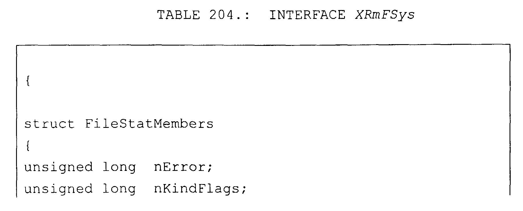


Table 94 is one embodiment of interfaces XSoundCallBack
and XRMSound that are included in one embodiment of
lightweight component 230. These interfaces are used
when a runtime environment component needs to play
sounds on user device 102i.


Table 95 is one embodiment of interface XRmStatus
that is included in one embodiment of lightweight
component 230. This interfaces is used when a runtime
environment component needs the status of user device
102i.

Those skilled in the art will readily understand that
the operations and actions described herein represent
actions performed by a CPU of a computer in accordance
with computer instructions provided by a computer
program. Therefore, lightweight component 230 may be
implemented by a computer program causing the CPU of
the computer to carry out instructions representing the
individual operations or actions as described
hereinbefore. The computer instructions can also be
stored on a computer-readable medium, or they can be
embodied in any computer-readable medium such as any
communications link, like a transmission link to a LAN,
a link to the internet, or the like.
Thus, lightweight component 230 can be implemented by a
computer program comprising computer program code or
application code. This application code or computer
program code may be embodied in any form of a computer
program product. A computer program product comprises
a medium configured to store or transport this
computer-readable code, or in which this computer-readable
code may be embedded. Some examples of
computer program products are CD-ROM discs, ROM cards,
floppy discs, magnetic tapes, computer hard drives,
servers on a network, and carrier waves. The computer
program product may also comprise signals, which do not
use carrier waves, such as digital signals transmitted
over a network (including the Internet) without the use
of a carrier wave.
The storage medium including the applications/services
executed on a server may belong to server computer
system 100 itself. However, the storage medium also
may be removed from server computer system 100. The
only requirement is that the applications/services are
accessible by server computer system 100 so that the
application/service corresponding to lightweight
component 230 can be executed by server 100.
Herein, a computer memory refers to a volatile memory,
a non-volatile memory, or a combination of the two in
any one of these devices. Similarly, a computer input
unit and a display unit refer to the features providing
the required functionality to input the information
described herein, and to display the information
described herein, respectively, in any one of the
aforementioned or equivalent devices.
While the present invention has been explained in
connection with certain embodiments thereof, other
embodiments will be apparent to those skilled in the
art from consideration of the specification and
practice of the embodiment of the present invention
disclosed therein. It is intended that the
specification and examples be considered as exemplary
only, without limiting the spirit and scope of the
invention.
In the following, further embodiments of the invention
will be described with respect to figs. 11 - 22.
The embodiments may be implemented in a software system
for providing the functionality (i.e. the services) of
runtime environment components from a server computer
system via a network to one or several client computer
systems.
The software system consists of two parts, one of them
being executed on a client, the other residing and
being executed on the server. The part on the server
platform makes up the runtime environment comprising a
plurality of runtime environment components which are
able to provide services. Furthermore, the part on the
server provides the necessary communication tools in
order to communicate with the client. The other part,
being executed on the client, performs mainly the
communication between the client requesting a runtime
environment component service and the part being
executed on the server which renders the runtime
environment component service requested. The server's
part of the software system is by far larger in size
than the client's part thereof. This latter part is
referred to as the 'lightweight component'. A typical
size of the software system's part on the server may be
50 to 100 Megabyte (e.g.: an office software package),
whereas the lightweight component on the client may
have a typical size of 400 Kilobyte, and may utilize
only little system resources (CPU power, memory).
The small size of the lightweight component makes it
attractive to download it within very short time from
the server to a client when the corresponding runtime
environment component service is actually needed. Then,
via the lightweight component, the client has access to
all the services presented by the runtime environment
components hosted on the server.
The lightweight component provides an application
programming interface (API) for any application program
the implementation of which on the client is allowed by
an implementation framework on the server. Two types of
lightweight components are explained in the following,
one being a standard component (referring to Figures 11
to 14), the other being a component rendering visual
functionality (referring in particular to Figures 15 to
19).
Computer Software programs and parts thereof, which are
called during execution of other computer software
programs or parts thereof, are referred to as runtime
environment components. The functionality provided by
these runtime environment components to calling
software programs or parts thereof are referred to as
runtime environment component services. In many cases,
runtime environment components have a very large size.
For example, office suites comprising drawing programs
and wordprocessors as well as other tools may have
sizes of 50 to 100 Megabyte which renders a
distribution over the Internet difficult. The runtime
environment components may be implemented in any
suitable form. They may consist of compiled software
program code to be executed or of script code in any
programming language to be interpreted before execution
by a compiler. Runtime environment components are
typically stored and administrated on a server.
The runtime environment component services, that means
the functionalities provided by runtime environment
components, which are, for example, stored on a server,
are made available for use in software programs to be
executed on, for example, clients without integrated
them into these software programs and without
distributing them together with these software programs
to the place of execution, for example, the clients.
Further, functionality of the runtime environment
components should is made available for all kinds of
clients whether they are powerful enough for storing or
executing the runtime environment component or not.
Further, the user of a client is not charged with the
problem whether a specific runtime environment
component is available on his client or not.
Reference is made to Fig. 11, which illustrates the
communication between the server 111 and an arbitrary
number of clients 112A, 112B which are connected via
communication network 113. The server 111 presents the
runtime environment component services to the clients
112A, 112B. Server 111 hosts components 1101, 1102,
1103, 1104, 1105, 1106 of the runtime environment as
well as a component 1100 for communication with the
clients 112A, 112B via a network 113. The network 113
is here assumed to be the Internet, although any other
network may be used as well. Each client 112A, 112B is
adapted to execute (at least) one software program
1250.
On each of the clients 112A, 112B a lightweight
component 1210 is implemented, which provides services
of the runtime environment components 1101, 1102, 1103,
1104, 1105, 1106 hosted on server 111 to a software
program 1250 running on the clients 112A, 112B. The
communication with server 111 is performed by the
communication component 1200 via the network 113. It is
to be noted that the lightweight component 1210 may
initially not be available on the clients 112A, 112B.
In this case, the lightweight component 1210 may be
downloaded on the clients 112A, 112B, for example, from
the server 111 upon the first request for runtime
environment component services which are accessible by
means of the lightweight component 1210.
It is assumed that on the clients 112A, 112B a software
program 1250 (e.g.: an Internet browser) is executed.
Whenever the software program 1250 calls for a runtime
environment component, for example an API 1101 for
providing a mathematical function, the lightweight
component 1210 receives this call. The lightweight
component 1210 then transforms this call into a request
and transmits it via the communication component 1200,
the network 113 and the communication component 1100 to
the server 111, where the API component 1101 called for
is residing.
Fig. 12 to 14 now illustrate the processing for
presenting / providing the runtime environment
component services in more detail.
Referring to Fig. 12, the lightweight component 1210
receives a call for an API component 1101 from the
software program 1250 running on the client 112A. With
the call, data (e.g. arguments) necessary for
performing the requested runtime environment component
service of API component 1101 is received. The
lightweight component 1210 transforms the received call
into a request to be transmitted over the network 113
to the server 111 which actually hosts the runtime
environment, including the now requested API component
1101.
The transmission of the request over the network 113 is
performed according to a predetermined transmission
protocol. The transmitted request contains the data
(e.g. arguments) from the calling software program 1250
for being processed by the API component 1101. If the
network 113 is publicly accessible, the transmission
may be encrypted according to known technologies.
Further, digital signatures can be used to provide
certification of the request mechanism being
established on the client for this runtime environment
component services system.
The request is received by the server 111 on which the
appropriate communication component 1100 is executed.
The communication component 1100 transforms and
decrypts (if necessary) the transmitted request,
performs digital signature processing, and accesses the
requested API component 1101 implementing the desired
mathematical function. This API component 1101 is
executed on the server 111, whereby the data (e.g.
arguments) received with the request are processed. The
result thereof is encrypted (if necessary) by the
communication component 1100 and transmitted from the
server 111 back to the client 112A.
The lightweight component 1210 on the client receives
and re-transforms the result (and decrypts it, if
necessary) and provides the result to the software
program 1250 having called for the service of the API
component 1101.
Thus, the lightweight component 1210 on the client 112A
delegates calls to the API component 1101, which may be
part of an implementation framework on the server 111.
The lightweight component 1210 operates hidden to the
calling software program of the client 112A. The called
runtime environment component 1101 is executed on the
server 111. However, the calling software program 1250
on the client 112A does not notice whether the
execution of the runtime environment component 1101 is
local, i.e. on the client 112A, or remote, i.e. on the
server 111. The calling software program 1250 does not
need to be modified for the use with the lightweight
component 1210, since, the call for a runtime
environment component is 'intercepted' and transformed
into a suitable request to the server 111 by the
lightweight component 1210, according to the invention.
On the other hand, local services available on the
client 112A, including devices like printers and local
storage, can also be utilized by the runtime
environment components on the server 111, in a
transparent manner. Transformation of the call of the
software program 1250 to the lightweight component 1210
and re-transformation of the result received from the
server 111 are performed "on the fly".
Fig. 13 illustrates the implementation of the
lightweight component 1210. As mentioned above, the
component 1210, which is necessary for transforming the
call can be kept relatively small. It can have a small
installation size and low usage of resources compared
to the runtime environment components on the server
111.
Fig. 14 exemplary illustrates the transparent access of
a runtime environment component via an object component
model. The object component model handles calls by
marshaling requests for runtime environment component
services through stub objects 1200' on the client 112A
and transmitting it over the network 113 to the server
111. There, the requests are unmarshaled through proxy
objects 1100'.
The stub objects 1200' and the proxy objects 1100' are
generated dynamically, for example, by the
communication component 1200 and by the communication
component 1100, respectively. Therefore, a caller does
not have to implement the stub objects 1200' and the
proxy objects 1100'.
Marshalling of a request is, in the present context,
understood as the process of embedding a request for a
runtime environment component service in a bit stream
for transmission over a network. The unmarshalling is
the inverse process of the marshalling.
The transmission concept through stub and proxy objects
is described in more detail in the Annex.
The stub / proxy object component model used here
implies that a lightweight component is able to access
any arbitrary runtime environment component 1101, 1102,
1103, 1104, 1105, 1106 available on the server 111, as
if it resided locally on the client 112A.
Referring to Figures 15 to 17, a further embodiment of
a lightweight component 1210 is explained. The
communication between the server 111 and the client
112A is performed via the network 113 by the respective
communication components 1100 on the server 111, and
1200 on the client 112A. The same encryption /
decryption mechanisms as indicated above may be
applied. In addition to the basic generic lightweight
component 1210 as described in connection with Figures
11 to 14, the lightweight component 1210 may include
the ability to perform graphic interaction and to
manage user interaction. In the following, such a
component is referred to as a visual lightweight
component. Such a graphic interaction may comprise
drawing visual contents on the client 112A, for
example, on a screen of a client laptop. Again, as
described above, the main part of the processing is
burdened on the runtime environment component residing
and running on the server 111.
The protocol which may be used for transmitting
graphical requests between the client 112A and the
server 111 is the Remote Visualization Process protocol
(RVP). RVP is a high level definition of a graphic
device defined as a set of interfaces. RVP is based
completely on a component infrastructure. This gives
RVP the ability to map functionality which a client
system is unable to support, to a service component on
the server side emulating this functionality.
The graphical environment may communicate with the
lightweight component 1210 through the Java Abstract
Window Toolkit layer (AWT). AWT stands for the
definition of the graphic and user interface layer for
the Java language. It is defined as a set of Java
classes and interfaces which are mapped to the concrete
implementation on different platforms. AWT is part of
the standard Java environment.
The service component on the server side uses a VCL
implementation as drawing engine. VCL (Visual Class
Library) is a C++ class library . It provides similar
to the AWT a set of classes and interfaces to build
graphical applications on different platforms. For
every platform there is a concrete implementation of
VCL. For the lightweight visual components, VCL
provides a special implementation, which transmits all
graphical requests for drawing over the network to a
client side, where these requests are intercepted and
mapped to a platform dependent graphic layer, which is
here AWT.
Again, the implementation framework on the server
handles drawing and user interaction transparently to
the component.
Fig. 15 illustrates RVP event processing. The visual
lightweight component 1210 is embedded in a graphical
environment, the graphical environment comprising a
display software program 1250 with a graphical user
interface (GUI). The graphical user interface is
referred to as a panel. An example of an implementation
is a Java bean which is embedded in an HTML page and
rendered by a browser. This Java bean represents a view
(in a window) of an office application component (e.g.
StarOffice Writer) or another visual office component.
An event from the graphical environment is passed to
the AWT 1260, and then interpreted by the RVP protocol
layer, which performs communication between the client
visual lightweight component 1210 and the remote office
runtime environment component implementation 1110 on
the server platform 111. From RVP 1220 the event is
marshaled by communication component 1200 and
transmitted to the server 111. There, it is unmarshaled
and passed to the RVP 1120 by communication component
1100, and dispatched by the VCL layer 1140.
The runtime environment component 1110 receives the
event. After the event is dispatched, the component
1110 is able to react to the event.
Fig. 16 illustrates the transmission of the response of
the component 1110 on the server 111 back to the
requesting client 112A. The requested service is here a
drawing functionality which is implemented by RVP
drawing. The office component (e.g. the StarOffice
Writer) 1110 is able to draw on a panel within software
program 1250 of the client 112A using the same
mechanism as described above. The component 1110 uses
the VCL 1140 as a drawing engine. The operations are
transmitted through VCL 1140, RVP 1120 and
communication component 1100 on the server 111 to the
client 112A. Client 112A receives the operations and
passes them to the AWT 1260 which is able to draw on
the panel of the client 112A directly.
Fig. 17 illustrates accessing an API as a runtime
environment component on the server 111 by the client
112A. The visual lightweight component 1210 is, in the
example described in Fig. 15 and Fig. 16, still able to
access transparently the full functionality of an API
1104 provided by the office component 1110. The request
of the lightweight component 1210 for API 1104 is
handed over to the office component 1110 through the
communication component 1200 on the client 112A and the
communication component 1100 of the server 111. Herein,
the request for the API 1104 generated by the
lightweight component 1210 may bypass RVP 1220 and AWT
1260 on the client 112A and likewise RVP 1120 and VCL
1140 on the server 111, if not drawing services are
requested. The latter would be the case, for example,
if API 1104 would provide calculation services. In
order to have the request bypass the mentioned
components the lightweight component 1210 must decide
that these components shall be bypassed. This decision
can be made by the lightweight component 1210 based on
the call of the API 1104 received from the software
program 1250 and the information that the API 1104 does
not provide drawing services. This information will
regularly be present in the lightweight component 1210,
since it has information about all runtime environment
components being available on the server 111 anyway,
since it has to request their services and receive
their responses. However, if necessary the office
component 1110 may also react to the request for API
1104 by drawing via RVP 1220 directly on the panel of
client 112A.
An exemplary scenario for the latter might be the
following: a user on client 112A editing a text
document displayed in his browser whishes to change the
font size to 10 points throughout the whole document.
For this purpose, the client 112A uses the API 1104 to
change all fonts throughout the whole document to a
size of 10 points. In this case, the office component
1110 running on the server 111 re-calculates the
display of the document, renders the document remotely,
and draws the document on the client 112A through the
RVP 1120 and RVP 1220.
However, if the user on client 112A changes the font
size only for newly input text lines, the currently
displayed document does not change, thus there is no
need to re-draw the whole document on the client 112A.
The event of changing the font size is passed via RVP
1120 to the office component 1104 and forces new
rendering of the document on the server 111. Since no
re-drawing of the document on the client 112A is
needed, the lightweight component 1210 does not have to
take any further action.
The participating components to create a Java bean
lightweight component in the frame of the office
application program package StarOffice used as a
runtime environment component are shown in Fig. 18. An
accompanying sequence diagram is supplied in Fig. 19.
The figures are reduced to show only needed relations
and methods to illustrate this specific process. A
StarOfficeBean represents a common java bean which is
derived from a java panel. It resides on the client as
the single instance Connector, which is responsible for
maintaining connections to the remote machine. All
client beans share one connection per user and server.
The OClientFactory created by the Connector is also
located at the client 112A. This enables the remote
Office Component to create elements which are specific
to the client 112A. Examples for these items range from
a simple frame window to a printer device handled
locally. Next the Connector establishes a connection to
the remote machine and starts the login process. If
succeeded the server 111 starts a StarOffice session
remotely and the Connector confirms the session with
Start(). The task of the remote MultiServiceFactory
created by the RVP Connection instance is to create
needed instances on the remote machine. Then a local
ORmFrameWindow is created and passed together with a
reference of the OClientFactory to the remote
StarOffice instance to be able for local dispatching
and drawing. By calling initialize() on the remotely
created JavaBeanFrame all actions are done and the
process of creating a StarOfficeBean is completed.
Unlike components like CORBA objects, lightweight
components 1210 do not have any additional code for
accessing the implementing object. Also the size of a
lightweight component 1210 does not increase with the
number of accessed runtime environment components of
the implementation server framework. This introduces
the ability to offer components which expose only
services designed for a special purpose and hide
complexity of the implementation framework.
By applying the invention, it is possible to include
for example full word processing functionality provided
by the server 111 into any other application program
1250 running on the client computer 112A.
Special purposes may be applications designed for being
executed on particular clients like handheld computers
or mobile telephones, where storage and processing
capabilities are particularly limited. Nevertheless,
the whole functionality of the framework is still
accessible.
Furthermore, when adding new runtime environment
components to the server 111, no modification on the
client side is necessary. Through the concept of
lightweight components, a new runtime environment
component on the server is immediately callable by the
client. The components are based on a generic
lightweight component which is able to communicate with
the implementation framework via the object component
model.
Fig. 20 refers to an example for using the present
invention. In this example a setup is used as described
in Fig. 15 to 17. Therefore, reference numerals also
relate to components which are presented and described
in more detail in connection with Fig. 15 to 17.
However, the method according to Fig. 20 does not
correspond to the methods described along Fig. 15 to
17.
In this example, a user utilizes his computer system as
a client 112A. This client 112A includes a screen on
which the user can edit and process a text document.
The client 112A includes text processing software 1250
with a limited scope of functionality and a lightweight
component 1210 which corresponds to comprehensive
services offered by an office suite software package
1110 located as runtime environment components on a
server 111 to which the client 112A is connected via a
network 113.
For the purposes of this example the user edits a text
document on the screen of the client 112A and changes
the font size of the text. In order to do this he
inputs his commands via a suitable input device of the
client 112A, for example, a keyboard. In step 2010 the
text processing software 1250 on the client 112A
requests the service "font change" from the lightweight
component 1210. The lightweight component 1210 receives
this request in step 2020. In step 2030 the lightweight
component 1210 marshals the request and transmits it
via the communication component 1200 in client 112A to
the communication component 1100 of the server 111 via
the network 113.
The server 111 unmarshals the request and calls the
runtime environment component 1110 in step 2040. In the
next step 2050 the component 1110 starts processing the
"font change" request. It will determine in step 2060
if a re-drawing of the text document on the screen of
the client 112A is necessary due to the requested font
change.
If not, the service component 1110 will immediately
produce a result to the request in step 2080. A re-drawing
may not be necessary, if the user wants the
font change to be effective exclusively for further
input into the text document. In this case the result
to be provided by component 1110 could be a return code
to the software program 1250 which tells the software
program 1250 that further input into the text document
will be processed with the new font on the screen of
the client 112A.
If yes, for example, if the font shall be changed for
the whole text document, the component 1110 renders a
new graphical presentation of the text document in step
2061. Then, in step 2062, the output operations for the
realization of the graphical presentation are given to
the VCL 1140 by the component 1110. In step 2063 it
will be decided by VCL 1140 whether the output
operations have to be carried out in a visible area,
e.g. on a screen.
If this is not the case, for example, if the text
document with the font changed throughout its entire
scope would only be stored as a data file but not shown
on the screen of the client 112A, the result would be
created in step 2090 by VCL 1140. This result would be
the text document in the new form. No display on the
screen of the client 112A would be envisaged in this
case.
If this is the case, for example, if the text document
shall be displayed on the screen of the client 112A,
the "change font" request realized by VCL 1140 is
transmitted to RVP 1120 in step 2064. This realized
request is then, in step 2065, marshaled and sent via
communication component 1100 of server 111, via the
network 113 and via the communication component 1200 of
the client 112A to the lightweight component 1210 on
the client 112A. In step 2066 the lightweight component
1210 unmarshals the realized request. In step 2067 the
request is translated into an AWT request. This AWT
request is transmitted in step 2068 from the
lightweight component 1210 via the RVP 1220 to the AWT
1260. In step 2069 the AWT 1260 executes the
transmitted AWT request. Finally, in step 2070 the
result will be transmitted to the software program 1250
so that the text document will be drawn on the screen
of the client 112A with the new font size.
Fig. 21 illustrates a non-visual lightweight component.
Non-visual means that the user of the client on which
the lightweight component is located does not receive
any hints as to its presence. He does not see it and he
can also not interact with it directly.
In Fig. 21 a client 2110 is shown with a screen
showing, on the left, a tree-like representation of
data files below a window, and, on the right,
information given about a certain text document which
was selected by the user by means of the tree-like
representation of data files. The client 2110 is
connected via network 2120 to a server 2130 which has
access to a text processing software program as runtime
environment component 2140. This component 2140 has in
turn access to a storage medium 2150 and to a library
2160.
If a user of the client 2110 wants to obtain
information, for example, number of words and lines,
author and date of this version, about a text document
chosen from the tree-like representation of data files,
he enters his request via an input device of the client
2110, for example, a keyboard of the client 2110. Then,
the non-visual lightweight component on the client 2110
will contact, as described above, via the network 2120
the server 2130 and ask for the services providing the
information requested by the user from the runtime
environment component 2140. The result provided by the
component 2140 will then be re-transmitted to the
client 2110 so that the desired information - number of
words and lines; author and date of this version of the
selected text document - can be displayed on the screen
of the client 2110. The lightweight component remains
non-visual to the user of the client 2110.
Fig. 22 in contrast shows an example of a visual lightweight component, that means a lightweight component with which the user may interact, but which will at least be recognized by the user in some situations.
Fig. 22 in contrast shows an example of a visual lightweight component, that means a lightweight component with which the user may interact, but which will at least be recognized by the user in some situations.
A client 2210 includes a visual lightweight component.
The client 2210 is connected via network 2220 with the
server 2230, which in turn has access to the runtime
environment component 2240 connected to storage medium
2250 and data base 2260.
In this example, a user of the client' 2210 edits a text
document on the screen of the client 2210, as shown in
Fig. 22 on the right, besides the above described
window and tree-like representation of data files. The
shown screen representation of the text document shows
in the right middle position a small window with which
the user may manipulate the displayed text document.
This window represents the lightweight component. Here,
the user may directly interact, via the window
presentation, with the lightweight component, which is
therefore referred to as a visual lightweight
component.
If the lightweight component is activated by a user
interaction it may contact, as described above, the
server 2230 and thereby the runtime environment 2240,
which may provide a service requested by the user by
his interaction from the client 2210.
Comparing a non-visual and a visual lightweight
component as above described, it may be advantageous to
use a non-visual lightweight component for processing
requests which do not require particular operations for
their fulfillment, in particular, no drawing operations
on a screen of a client. In this case, the non-visual
lightweight component may provide the response to the
request more quickly than a visual lightweight
component, since, for example, drawing operations are
not processed at all; they are not only ignored by the
client after having been processed with great efforts.
In the following, further embodiments for remote
control and interaction with a run time environment
component will be described.
receiving by said user interface infrastructure a remote input action event via said communication network, said remote input action event being generated in said second computer system by a lightweight component corresponding to said runtime environment component service.
transmitting an input event to said runtime environment component service by said user interface infrastructure in response to said remote input action event.
processing said input event by said runtime environment component service.
generating a graphic user interface command to said user interface infrastructure by said runtime environment component service.
transmitting a remote graphic user interface command to said lightweight component by said graphic user interface infrastructure in response to said graphic user interface command.
receiving said local output command by a local window object and in response generating said remote output command by said local window object
receiving said remote input action command by a local window object and in response generating said local input action command by said local window object.
receiving said remote input action command by said local window object, and in response generating said local input action command by said local window object.
generating an instance of a local window on said computer system by said service, wherein said local window issues remote instructions to said remote window frame in response to instructions from said runtime environment component service.
querying said remote frame window by said local window to determine properties of said remote frame window.
generating, on said computer system, a local frame for said local window.
receiving, by said local frame, a command from said user device to load a document.
issuing, in response to said command to load a document, a command by said local frame to said runtime environment component service to create an instance of a runtime environment component service window on said computer system.
issuing a command by said local frame to said runtime environment component service to load said document in said runtime environment component service window.
issuing a command from said runtime environment component service to said local window to display said document.
downloading lightweight component into said user device.
a bean frame class comprising a frame interface.
an abstract windowing toolkit.
A user device, a first computer system, includes a
lightweight component that receives user input actions
for a runtime environment component that is executing
on a second computer system. The lightweight component
sends a remote input action command to a user interface
infrastructure that is executing on the second computer
system. In response to the remote input action
command, the user interface infrastructure sends a
local input action command to the runtime environment
component that processes the command, and issues a
local output command to the user interface
infrastructure that in turn sends a remote output
command to the lightweight component on the user
device. In response to the remote output command, the
lightweight component causes an output on the user
device.
CHAPTER D describes a method and device for
representing data.
The present invention relates to a method and a system
for the individual representation of data, e.g. in the
network portal system of CHAPTER A.
Information requested by a user device naturally needs
to be in a format to be understood by this specific
user device. Therefore, in many instances information
is only accessible to a certain group of user devices.
For example, homepages of individuals or companies
provided by a webserver over the internet are generally
available only to specific user devices, namely
computer systems supporting the regular homepage data
format html. However, the access of other user devices
to this information may also be desirable. Such user
devices may be, for example, handheld computers or
mobile phones.
Unfortunately, the Internet browsers that process and
display the HTML homepages typically require over 50
Megabytes of storage, which is not available on
handheld computers or mobile phones.
Alternative methods are available, for example, that
permit mobile telephones to send and receive
information from the Internet. Typically, a program
executing on the telephone transmits a URL, or a
representation of a URL to a server that translates the
request, and retrieves the data over the Internet. The
server then converts the retrieved content into a
format that can be interpreted by the mobile telephone
and transmits the data to the mobile telephone for
display. See for example, U.S. Patent Number 5,809,415
of Rossmann entitled "Method and Architecture for an
Interactive Two-Way Data Communication Network."
Another similar approach is described in U.S. Patent
No. 5,727,159, entitled "System In Which a Proxy-Server
Translates Information Received From the Internet Into
a Form/Format Readily Usable by Low Power Portable
Computers," of Kikinis issued on March 10, 1998. In
this approach, a specialized browser must be installed
on each device that communicates with a proxy-server
that in turn communicates with the Internet. A device
that does not have the specialized browser, or cannot
execute the specialized browser cannot retrieve or
display content using the proxy-server.
Thus, the prior art teaches that it is necessary to
develop an independent technique to provide access to
particular information. For example, the prior art
technique for mobile phones was not used on portable
computers and conversely.
Therefore, it is desirable to provide a method and a
system allowing the access of data, particularly over a
network, to a variety of different user devices,
including mobile phones and handheld computers.
A method for presenting data on a user device with
presentation requirements relating to the presentation
of this data on the user device, comprises the
following steps:
Herein, the step c) may be carried out by the data
presentation management means. The inventive method may
also comprise the step d) of applying the presentation
scheme to the data to create presentable data to allow
the presentation of the data on the user device. This
step d) may be carried out by the data presentation
management means. However, step d) may also be carried
out by the user device or by any other device which
applies the presentation scheme and provides the
presentable data to the user device.
The aforementioned method may be supplemented by the
further step e) of transmitting the presentable data to
the user device to allow the presentation of the data
on the user device.
The data may be retrieved by the data presentation
management means before the application of the selected
presentation scheme to the data. In another embodiment
of the present invention the data may be retrieved by
the user device itself. Then, the selected presentation
scheme may be applied by the user device or by the
presentation management means. The latter would, for
example, apply, if the data retrieved by the user
device would be transferred to the presentation
management means for applying the selected presentation
scheme and than be re-transferred to the user device.
In the scope of the present invention a method is also
provided for obtaining data by a user device having
presentation requirements relating to the presentation
of the data on the user device, comprising the
following steps:
Furthermore, a method is provided for obtaining data by
a user device having presentation requirements relating
to the presentation of the data on the user device,
comprising the following steps:
Herein, the user device may receive the data via data
management presentation means, as described earlier.
Data in the scope of the present invention is the
representation of information. This information can be
presented by any suitable means, for example, text,
picture, sound, movie or action. Different kinds of
information can also be combined. This data may be
accessible to the user device, for example, via a
network. For the retrieving of the data certain
requirements of the user device have to be considered.
Such requirements may be of different type. They
include presentation requirements. They may further
have different origin. For example, the requirements
may be caused by the software on the user device, which
may support only specific kinds of information. It may
also be possible that the requirements depend of the
hardware of the user device, if the user device can,
for example, present information merely via a
loudspeaker. User depending requirements are also
possible in the scope of the present invention. This
may be caused by certain preferences of the user as
well as by a handicap.
In the scope of the present invention data includes
also functions. Such functions may be, for example,
actions for presenting data, for example, movies and
sound as well as function for processing on data like,
for example, calculation functions or spellchecker.
A user device according to the present invention may
be, for example, a computer system comprising at least
a processor, a storage medium and an i-/o-interface.
Via this i-/o-interface the user device may be
connected to the source of the data. It will also be
possible that the requested data is stored on the
storage medium of the user device. Regularly, the user
device comprises also input and output devices
connected via the i-/o-interface.
The requested data may be retrieved via at least one
portlet. In the context of the present invention a
portlet is understood to be means for providing the
requested data from a data source, for example, from a
certain homepage or data base.
Two or more portlets may be arranged in tree-like
organization. This tree-like organization may be
presented to a user of the user device, for example, on
a screen of the user device, so that this user has the
possibility to easily choose among the offered
portlets.
The presentation requirements of the user device may be
determined based on information about the user device.
For example, if the data presentation management means
are informed about the type of the user device they may
conclude therefrom the presentation requirements of the
user device.
In the context of the present invention data
presentation management means are hardware or -
generally - software means for managing the
presentation of data on a user device. Their exact
functionality depends on the implementation of the
present invention. The functionality of the data
presentation management means includes at least the
selection of the presentation scheme for the requested
data in accordance with the presentation requirements
of the user device. For this purpose the data
presentation management means must be informed about
the presentation requirements of the user device.
Furthermore, the functionalities of the data
presentation management means may include the
application of the selected presentation scheme on the
requested data in order to create presentable data to
be presented by the user device. This requires the
availability of the requested data for the data
presentation management means. The retrieval of this
data may also be carried out by the data presentation
management means.
The presentation schemes may be defined, for example,
in an extensible stylesheet language (XSL). XSL is a
language for creating a stylesheet which describes how
content being formatted in an extensible markup
language (XML) will be presented to a user device. The
presentation scheme may describe, for example, if a
certain content defined in XML will be displayed, where
this content will be displayed and how it will be
displayed.
The methods of the present invention may be implemented
in a computer program (computer program product),
including comprehensive office applications. A computer
program product comprises a medium configured to store
or transport computer readable code, or in which
computer readable code may be embedded. Some examples
of computer program products are: CD-ROM disks, ROM-cards,
floppy disks, magnetic tapes, computer hard
drives, servers on a network and carrier waves and
digital signals transmitted over a telecommunication
link or network connection.
Such a computer program may be stored on any common
data carrier like, for example, a floppy disk or a
compact disk (CD), as well as on any common computer
system's storage facilities, like hard disks.
Therefore, the present invention also relates to a data
carrier for storing a computer program for carrying out
the inventive methods. The present invention also
relates to a method for using a standard computer
system for carrying out the present inventive methods.
In the scope of the present invention a computer system
is provided comprising at least a processor, a memory
and an i-/o-interface for representing data depending
on presentation requirements of a user device relating
to the presentation of the data on the user device,
comprising data presentation management means, wherein
the data presentation management means include:
Furthermore, the computer system may comprise
The retrieving and the applying functions may also be
carried out in a user device or in a computer system
being accessible to the user device. Therefore, the
retrieving module and the applying module may also be
located in the user device or in any computer system
which is connectable or connected to the user device
and which is able to deliver the result of the
application of the presentation scheme, the presentable
data, to the user device.
The aforementioned computer system may be supplemented
by a transmitting module e) for transmitting the
presentable data to the user device to allow the
presentation of the requested data on the user device.
According to an embodiment of the present invention, a
method and a system allow access to data, particularly
over a network, to a variety of different user devices,
including mobile phones and handheld computers. Unlike
the prior art methods, this method and system are not
limited to devices that have either a predefined
configuration, or predefined software loaded on the
device. Rather, the presentation requirements of a
device are determined, and a document compatible with
those presentation requirements is generated by a
presentation manager server system.
Consequently, the problems associated with updating and
providing specialized software to each type of user
device have been eliminated. Also, it is no longer
necessary to write specialized software for each type
of user device that is provided data from a single
content source, or for each content source that has a
different data format.
In one embodiment, a method for presenting data on a
user device comprises:
In one embodiment, this method also includes applying
the presentation scheme to the data to create the
presentable data. This operation is performed by the
presentation manager, by the user device, or by any
other device, which applies the presentation scheme and
provides the presentable data to the user device. The
aforementioned method may be supplemented by
transmitting the presentable data to the user device to
allow the presentation of the data on the user device.
In another embodiment of the present invention, a
method also is provided for obtaining data by a user
device having presentation requirements relating to the
presentation of the data on the user device. This
method includes submitting a request to obtain data by
the user device to a presentation manager coupled to
the user device. The request causes the identification
of the presentation requirements of the user device to
the presentation manager, and the selection of a
presentation scheme for the data in accordance with the
presentation requirements of the user device by the
presentation manager. The request further causes the
application of the selected presentation scheme to the
data to create presentable data. This method further
includes receiving in the user device the presentable
data to allow the presentation of the data by the user
device.
In one embodiment of the present device, the data
requested is retrieved via at least one portlet coupled
to the presentation manager. Herein, a portlet is
understood to be means for providing the requested data
from a data source, for example, from a certain
homepage or database to the presentation manager.
Two or more portlets may be arranged in tree-like
organization. This tree-like organization is presented
to a user of the user device, for example, on a display
screen of the user device, so that this user has the
possibility to easily choose among the content offered
via the portlets.
In one embodiment, the presentation requirements of the
user device are determined based on information about
the user device. For example, if the presentation
manager is informed about the type of the user device,
the presentation manager can determine therefrom the
presentation requirements of the user device and select
a presentation scheme based thereon.
Presentation schemes may be defined, for example, in an
extensible style sheet language (XSL). The
presentation scheme may describe, for example, if a
certain content defined in XML is displayed, where this
content is displayed and how this content is displayed.
In another embodiment of the method of this invention,
a request is received from a user device. The request
was generated in response to a selection of a portlet
identification object on the user device. The request
is transferred to a portlet. The portlet retrieves
data specified in the request over a network. This
data has one format in a plurality of source data
formats.
The request also is analyzed to determine a user data
format that is supported by the user device. A
presentation scheme to convert the data from the source
data format to the user data format is then selected.
The retrieved data is converted from the source data
format to the user data format using the presentation
scheme.
In one embodiment of selecting a presentation scheme
includes selecting an XSL-stylesheet. The received
request includes, in another embodiment, a command.
The command is selected from a group of commands
consisting of load, save, article, and channel.
In yet another embodiment of the present invention, a
web server receives a request from a user device. The
request was generated by selection of a portlet
identification object on the user device. The web
server analyzes the request to determine whether the
request is for content associated with a portlet. The
request is transferred to a presentation manager upon
the web server determining that the request is for
content associated with a portlet. The presentation
manager passes the request to a portlet. The portlet
retrieves data specified in the request over a network.
The retrieved data has a source MIME type.
The presentation manager analyzes the command to
identify a user MIME type, and then selects a
presentation scheme from a plurality of presentation
schemes based upon the user MIME type and the source
MIME type. The presentation manager converts the data
from the source MIME type to the user MIME type using
the presentation scheme.
Thus, in one embodiment of the present invention, a
presentation manager server system includes a web
server, a presentation manager coupled to the web
server, and at least one portlet coupled to the
presentation manager. The at least one portlet may
comprise any one of a mail portlet, a resource
description framework portlet, and an internal network
information portlet. A portlet is associated with
content that is retrieved by that portlet. The
presentation manager server system also may include a
storage medium having stored thereon a plurality of
presentation schemes.
In one embodiment of the presentation manager server
system the web server comprises a servlet container,
and the presentation manager comprises a servlet.
A computer program product, according to one embodiment
of the present invention has stored thereon computer
instructions for a method comprising:
A computer program product, according to another
embodiment of the present invention has stored thereon
computer instructions for a method comprising:
A computer program product, according to yet another
embodiment of the present invention has stored thereon
computer instructions for a method comprising:
The present invention will now be described in detail
on the basis of examples, where reference will be made
to the appended figures, which show:
- Fig. 1A
- illustrates one embodiment of a network including a plurality of user devices coupled to a presentation manager server system according to one embodiment of the present invention.
- Fig. 1B
- is a more detailed illustration of one embodiment of user device 102A of Figure 1A including portlet icons according to one embodiment of the present invention.
- Fig. 2A
- is a process flow diagram according to one embodiment of the present invention.
- Fig. 2B
- is a process flow diagram for selecting portlets that can be accessed by a user device according to one embodiment of the present invention.
- Fig. 3
- is a more detailed illustration of the presentation management server system according to one embodiment of the present invention.
- Fig. 4
- is a more detailed process flow diagram of the retrieve scheme operation of Figure 2A.
- Fig. 5
- is sequence diagram for the portlet manager according to one embodiment of the present invention.
- Fig. 6
- is an example of a class PortletManager that is used to instantiate the portlet manager object according to one embodiment of the present invention.
- Fig. 7A and 7B
- are an example of method do Post and do Get according to one embodiment of the present invention.
- Fig. 8A and 8B
- are an example of a class CommandFactory that includes method producecommand according to one embodiment of the present invention.
- Fig. 9A to 9E
- are an example of a class LoadCommand according to one embodiment of the present invention.
- Fig. 10A and 10B
- are an example of a class SaveCommand according to one embodiment of the present invention.
- Fig. 11A to 11J
- are one embodiment of class ChannelCommand according to one embodiment of the present invention.
- Fig. 12
- is a block diagram of modules in the portlet manager according to one embodiment of the present invention.
- Fig. 13
- is a schematic representation of an example for the method and system of the present invention,
- Fig. 14
- is schematic representation of the screen print of a user device using the present invention,
- Fig.15
- is a flow chart showing obtaining the presentation requirements of a user device,
- Fig. 16
- is a flow chart showing the steps to be carried out by a method according to the present invention, and
- Fig.17
- is flow chart showing the operation of a method of the present invention.
In the Figures 1 - 17 of CHAPTER D and the following
Detailed Description of CHAPTER D, elements with the
same reference numeral are the same element or a
similar element. Also, the first one or two digits of a
reference numeral for an element indicate the figure in
which that element first appeared. Reference numerals
do not necessarily correspond to the reference numerals
used in the further chapters.
According to the principles of this invention, a single
presentation manager 113, executing on a presentation
manager server system 100, accesses information from
any one of plurality of content sources 101A to 101C in
response to a request from any one of a plurality of
user devices 102A to 102F. Each of the plurality of
user devices 102A to 102F may have different
requirements for presentation of information retrieved
by presentation manager 113, i.e., different
presentation requirements. When a request for
information is received from a particular user device,
presentation manager 113 retrieves the information,
identifies the presentation requirements of the
particular user device, and then transforms the
information, if necessary, using a presentation scheme
specific to the user device so that the information can
be presented on the particular user device.
The presentation requirements may be any conditions or
limitations on the presentation of data on the user
device, for example, kind and size of display on the
user device, type of programming language or data
format supported by the user device, or any other
presentation requirements of the user device, for
example, of the processor or the memory. These
presentation requirements not only may result from
technical necessities, but also may result from an
individual user's demands or wishes. The user is not
constrained to accessing data in a format that is
compatible with the one particular device that the user
happens to be using as in the prior art.
Hence, presentation manager server system 100 solves
the prior art information access limitations by giving
users access from whatever device is available at the
time, through a single system entry point, to a
complete complement of data. As explained more
completely below, presentation manager server
system 100 frees a user from time and location
constraints when accessing the complete complement of
data.
A user can access data on Internet 106 and/or
enterprise network 103 from almost any available
device, e.g., any one of a portable computer 102A, a
mobile telephone 102B, a workstation 102C, a home
personal computer (PC) 102D, a personal digital
assistant 102E, or an Internet café machine 102F. No
longer is a user limited to using a particular device
with pre-installed software to access a particular type
of data accessible via a network to which the device is
coupled.
For example, a user taps an icon displayed on PDA 102E
to generate a request for a sales report that is stored
in a database on legacy system 101C. The request is
sent over Internet 106 to presentation manager 113
that, in turn, retrieves the sales report via an
internal portlet 117, transforms the sales report
according to a presentation scheme for PDA 102E, and
transmits the transformed sales report to be displayed
on PDA 102E. A similar transaction could be done using
Internet café machine 102F, or perhaps mobile
telephone 102D.
Each user device in the plurality of user devices 102A
to 102F accesses information through the same portlet.
However, in a first embodiment, presentation
manager 113 retrieves the information using the portlet
and then transforms the information using a
presentation scheme that is specific to the user device
so that the retrieved information can be displayed by
the user device. Alternatively, presentation
manager 113 could provide the presentation scheme and
the retrieved data to the user device and the
transformation of the retrieved data could be done on
the user device itself.
Plurality of devices 102A to 102F is illustrative only
and is not intended to limit the invention to the
particular devices illustrated. The devices could also
include, for example, a POTS telephone, a pager, a set-top
box connected to a television, a network appliance,
or any other device that is connectable to a network
and can issue a request for data, as described more
completely below, and display the data received in
response to the request. This embodiment of the
present invention is not limited to a particular type
of user device or to a particular group of user devices
as in the prior art, or to user devices that are
running a particular software program.
The user can access multiple content sources via
presentation manager server system 100. Different
types and formats of data from different applications
can all be accessed and processed within a single user
interface. Further, data from external sources, such
as stock quotes, weather forecasts, or perhaps news
tickers from web-based service providers can be
accessed using the same single user interface.
According to the principles of this invention,
presentation manager server system 100 is a
comprehensive client/server offering that enables
users, from almost any device anywhere, to access and
view different types of data from a wide variety of
content sources.
As an example, consider user device 102A (Figs. 1A
and 1B) that is a portable computer. The display on
display screen 150 includes, within a work area, three
portlet icons, e.g., an internal page icon 120, an
external page icon 121, and a news ticker icon 122. In
this example, the use of icons to represent portlets is
illustrative only and is not intended to limit the
invention to this specific embodiment. For example, a
list of text names could also be used. In general, a
portlet identifier is provided to a user, and upon
selection of the portlet identifier by the user, a
request is sent to presentation management server
system 100 to retrieve and return content associated
with the portlet identifier.
In an explorer region on display screen 150 is a mail
icon 121. If the user selects mail icon 121, a
hierarchical view is generated on display screen 150A
as illustrated in Figure 1B, each entry of which
represents a portlet that can be used, in one
embodiment, to request information from presentation
manager server system 100. Corresponding to each icon
displayed on user device 102A is a portlet, e.g.,
portlets 115 to 117 that are coupled to presentation
manager 113, as explained more completely below.
Alternatively, icons 120 to 122 on display screen 150
could each expand into a hierarchy of icons. Moreover,
upon selection of an icon, typically by the user
placing a cursor on the icon and clicking a mouse, the
user could be presented, for example, with an input
screen in which the user input commands for acting on
data. When the user completes the input screen, a
request that includes the commands for acting on data
is dispatched to presentation manager server
system 100.
Thus, according to the principles of this invention, a
portlet icon, or more generally, a portlet identifier,
is not limited to issuing only a request to retrieve
information. The user-initiated request can also
include commands that perform operations on data, for
example. However, in each case, a portlet icon is
associated with a specific source of information,
sometimes called content, as explained more completely
below.
Instead of the screen portlet icons in Fig. 1B, the
portlets may also be offered to the user in the form of
a text based listing on the display of the user device.
This listing may be put together in presentation
manager 113, for example, in the eXtensible Markup
Language (XML) format. In addition, the user can
obtain a list of information sources available through
presentation manager server system 100 by issuing a
request to presentation manager 113 that is not
addressed to a specific portlet. With this list, the
user can select portlets of interest to the user, as
explained more completely below with respect to Fig.
2B.
Thus, an individual user can personalize the user
device by specifying which service providers from among
the ones the organization has made available via
portlets, the user wants to use. To put it another
way, the user chooses which portlets the users wishes
to be included on the desktop as illustrated in Fig.
1B. (A portlet is the smallest unit of information
that can be put in a portal.) Hence, presentation
manager server system 100 eliminates prior art
limitations on a single user system on a network
accessing content on any desired provider system that
is coupled to the network.
When a user selects one of the icons on display
screen 150, user device 102A, which is coupled to a
network server 111 by an enterprise network 103, issues
a request associated with the selected icon. The
request specifies (i) a suitable address to the
location where the content associated with the request
is stored, for example, the Internet address of a
homepage in the form of a uniform resource locator
(URL), and (ii) information concerning either the types
of data that can be processed and displayed by user
device 102A, e.g., MIME types, and/or, an identifier
that indicates the processing and display capabilities
of user device 102A. In addition, the request can
include operations that are to be performed on the
data, or using the data, e.g., find all web sites
including the word or words specified in the request.
Enterprise network 103 is illustrative only of one
embodiment of a network. The particular type of
network connecting a user device to presentation
manager server system 100 is not essential, and may be
the Internet or any other permanent or temporary
network, for example a local area network.
Upon receipt of the request, network server 111 in
presentation manager server system 100, which in one
embodiment is a web server, determines that the request
is for data accessed via presentation manager 113 and
transfers the request to presentation manager 113.
Upon receipt of the request from network server 111,
presentation manager 113, as explained more completely
below, passes the request to the portlet associated
with the request. For example, if the user issued a
request for all new mail messages, presentation
manager 113 would pass the request to mail portlet 115
that is associated with mail system 101A. If the
request was for information on an external network,
presentation manager 113 passes the request to external
portlet 116 that may be associated, for example, with
one of web sites 101B. In one embodiment, portlet 116
accesses web sites 101B that provide content using the
Resource Description Framework (RDF).
The portlet that receives the request from presentation
manager 113 retrieves the requested data and returns
the data to presentation manager 113. Typically, each
of the plurality of portlets 115 to 117 accesses data,
i.e., content, in a different format. Of course, one
or more portlets could be configured to retrieve data
having the same format. For example, text based
information may be provided in the HTML format as well
as in the WML format.
In addition to passing the request to the appropriate
portlet, presentation manager 113 identifies the
presentation requirements of the user device for the
requested data. Using the identification of the
presentation requirements, presentation manager 113
selects a presentation scheme for the requesting user
device.
As used herein, the presentation scheme for a user
device is the totality of the configuration information
needed to extract data from a first format and
transform the data into new data for presentation on
that user device. In one embodiment, as explained more
completely below, the presentation schemes include a
plurality of eXtensible Style sheet Language (XSL)-stylesheets
that is stored on a storage medium for
access by presentation manager 113. Each XSL-stylesheet
transforms eXtensible Markup Language (XML)
data to new data that can be processed and displayed by
a particular user device, sometimes referred to as user
device presentable data.
In selecting a presentation scheme, in one embodiment,
presentation manager 113 determines whether the request
from the user device includes a specific identification
of a presentation scheme; a list of MIME types that the
user device is capable of displaying; and either a user
identification and/or a device identification. If the
user request specifies a specific presentation scheme,
for example, a particular XSL-stylesheet, presentation
manager 113 selects that stylesheet as the presentation
scheme. If a MIME type is specified in the request and
presentation manger 113 has an XSL-stylesheet for
transforming the requested content to that MIME type,
this XSL-style sheet is selected. If the requested
content is in a MIME type that is in the list of MIME
types in the request, presentation manager 113 simply
passes the retrieved content straight thru. If
presentation manager 113 cannot identify a specific
presentation scheme for the requested data,
presentation manager 113 simply passes the retrieved
content straight thru, in one embodiment. Thus, in
each instance, presentation manager 113 identified the
presentation requirements based upon information
specified in the request, and selected an appropriate
presentation scheme.
The presentation scheme selected by presentation
manager 113 is retrieved and loaded into a local
memory. When the requested data is available in a
memory addressable by presentation manager 113,
presentation manager 113 uses the stored presentation
scheme to process the stored data and thereby generate
user device presentable data, which may be presented in
accordance with the requirements of user device 102A
that transmitted the original request. Finally, the
user device presentable data is transferred to user
device 102A over the network coupling user device 102A
to presentation manager server system 100.
Hence, through use of a dynamic content channel, e.g.,
a portlet, a highly customizable content page may be
produced for any individual client system. Moreover, a
particular user device is not limited to accessing
content in a format identical to that associated with
the user interface in use on the user device.
Consequently, the user's ability to access a wide
variety of content sources independent of the
characteristics of the particular user device is
further enhanced with the portlets in this embodiment
of the invention.
As used herein, a user device and/or a computer system
includes at least a processor, a storage medium, and an
I/O-interface. In the context of the present
invention, data refers to any type of information,
which is arranged in certain order to be accessible by
a computer system. The data to be accessed may also
include one or more functions or functionalities
provided to the user of a user device. Functions are,
in this context, possibilities given to the user to
initiate actions beyond the mere retrieval or display
of information, for example, a search on the Internet
for a certain publication or the initialization of a
software program on a remote server carrying out some
operations in response to the user device's request.
Figure 2A is a process flow diagram of one embodiment
of a method 200 the present invention. Figure 3 is a
more detailed block-level diagram of one embodiment of
presentation manager server system 100 that implements
method 200 of Figure 2A. In this embodiment, network
server 111 is a web server 111, and presentation
manager 113 is a portlet manager 113.
As explained above, a user initiates a request on a
user device by selecting a portlet identifier, e.g., an
icon, for example, that represents a particular
instance of data that is accessible via a particular
portlet in presentation manager server system 100. In
this embodiment, an icon representing a portlet is only
selectable for display on display screen 150 (Fig. 1B)
if the data provided by the portlet may be presented by
the user device. For example, if the user device does
not support graphics, a portlet, which provides data
with the MIME type image/jpeg, would not be available
for selection for display on display screen 150 of
device 102A.
In one embodiment, this pre-selection of portlets
offered to the user is made by a comparison of the MIME
types supported by the user device and the MIME type of
data for each of the portlets. Fig. 2B is a process
flow diagram of a method 280 that is used in one
embodiment of the present invention to preselect
portlets that are made available to a particular user
device. Method 280 is not started unless a user issues
a request to select one or more portlets for a
particular device. This is represented by preselect
portlet for access request check operation 281 that
typically is part of a graphic user interface event
handler, or part of a windowing system event handler.
Upon the user issuing a request to preselect one or
more portlets, check operation 281 designates the
portlet selected, or one of the portlets selected, as
the current portlet and transfers processing to get
user MIME types operation 282. In operation 282,
presentation manager server system 100, in this
embodiment, obtains the MIME types supported by the
user device, i.e., obtains the user MIME types, and
transfers to get source MIME types operation 283.
In operation 283, the source MIME types supported by
the current portlet are retrieved and processing
transfers to common MIME type check operation 284. If
at least one of the user MIME types and one of the
source MIME types are the same MIME type, processing
transfers to portlet available operation 287, and
otherwise to generate MIME type set operation 285.
In generate MIME type set operation 285, presentation
schemes 303 are used to generate another set of MIME
types, which are the MIME types produced when
presentations schemes 303 are applied to the source
MIME types. Operation 285 transfers processing to
common MIME type check operation 286.
If at least one of the user MIME types and one of the
MIME types in the set of MIME types generated by
operation 285 are the same MIME type, processing
transfers to portlet available operation 287, and
otherwise to portlet unavailable operation 288.
In portlet available operation 287, the current portlet
is flagged as available to the user device and an
appropriate response is supplied to the user device.
For example, the portlet icon could be installed on the
user's desktop.
In portlet unavailable operation 288, the current
portlet is flagged as unavailable. In this case, a
message is sent to the user that access to the portlet
is not available from this user device.
Both operations 287 and 288 transfer to additional
portlets check operation 289. If the user requested to
preselect more the one portlet, the next portlet in the
user request is identified as the current portlet, and
operations 283 to 288 are repeated, as appropriate. If
the user only requested to preselect one portlet, or
all of the portlets have been processed, check
operation 289 passes to the end operation that cleans
up and exits.
In the above example relating to graphics, the
presentation capabilities of the user device did not
support graphics. The comparison with the MIME type of
data defined by the various portlets shows that a
portlet defining image/jpeg as its MIME type of data
cannot be supported by this user device. Accordingly,
the user device via method 280 would be denied access
to this particular portlet.
Method 280 may be made at any suitable location, for
example, in the user device as well as in web
server 111, in portlet manager 113, or in the
respective portlet itself. Consequently, in the
following description, when user device submits a
request in operation 210, no subsequent checking is
done to assure that the requested data can be displayed
on the user device. However, in another embodiment,
the user is allowed to send requests to all available
portlets, and as each request is sent, if the request
cannot be processed for whatever reason, an error
message is returned to the user device.
The request transmitted in send request operation 210
(Fig. 2A) includes at least a description of the
requested data. Such a description may be, for
example, the URL of the data. The request typically
also includes the MIME type or types supported by the
user device, e.g., wireless application protocol (WAP)
for mobile phone 102B. The request may also include
either or both of the identity of the user device and
the identity of the user of the user device. As
explained more completely below, the request may
further include a command, such as channel, load, save,
or article.
The request from the user device in operation 210 goes
over a network to server 111, which in this embodiment
is a web server 111. In one embodiment, web server 111
is the Tomcat server supplied by The Apache Software
Foundation, 1901 Munsey Drive, Forest Hill, MD 21050-2747,
U.S.A. However, in this embodiment, any HTTP
server that supports the functionality and operations
described herein can be used as web server 111. In one
embodiment, web server 111 is a servlet container, and
portlet manager 113 is implemented as a servlet.
In portlet check operation 215, web server 111 analyzes
the request from the user device, sometimes referred to
as the original request, to determine whether this
request has to be processed by portlet manager 113.
The alternative is to process the request directly by
web server 111.
Check operation 215 can be implemented in various
alternative ways. In one embodiment, deployment
descriptors as defined in the JAVA 2 Enterprise Edition
are used and checked in operation 215 to determine
where to direct the user request. The JAVA 2 Platform
Enterprise Edition Specification, v1.2, Sun
Microsystems, Inc., Palo Alto, CA (1999) and the JAVA
Servlet Specification, v2.2, Sun Microsystems, Inc.
Palo Alto, CA (1999) are incorporated herein by
reference to show the level of skill in the art. Based
upon the deployment descriptors, if the request is for
web server 111, processing transfers to continue
operation 217 and conventional processing continues.
Otherwise, the request is forwarded to portlet
manager 113 and processing transfers to contact portlet
operation 220.
In another embodiment, the decision in check
operation 215 is based on the MIME type of the
requested data, i.e., the MIME type of the data located
at the URL in the request, and the MIME type supported
by the user device. If the MIME type of the requested
data and the MIME type supported by the user device are
identical or at least compatible, the request is
processed by web server 111. This condition is
frequently fulfilled, for example, if a browser, which
is able to handle and to process data in XML, requests
a homepage, which is also formatted in XML.
Thus, if the request is supported by web server, 111,
processing transfers to continue operation 216 and
conventional processing continues. Otherwise, the
request is forwarded to portlet manager 113 and
processing transfers to contact portlet operation 220.
Portlet manager 113 may be implemented in software
within web server 111, or may be installed on a
separate computer system, which is connected or
connectable to web server 111. In one embodiment,
portlet manager 113 is implemented as a servlet that
executes on web server 111.
Typically, portlet manager 113 is not continually
executing on web server 111, and so if a request is
forwarded to portlet manager 113 in contact portlet
operation 220, portlet manager 113 is started and then
the request is forwarded to portlet manager 113 for
processing.
Portlet manager 113 forwards the request to the
appropriate portlet. The forwarding of the request to
a specific portlet completes contact portlet
operation 220. The portlet retrieves the data in
retrieve data operation 230, and processing in portlet
manager 113 transfers to MIME check operation 240
within identify user type operation 245. In Figure 2A,
the operations are shown as sequential for ease of
illustration only. This is not intended to limit the
invention to this specific sequence of operations. The
specific sequence will depend upon the computer system
used and the specific implementation of this
embodiment.
The request from the user device contains information
about the presentation requirements of the requesting
user device, or contains information about the identity
of the user device, or contains both. If the request
contains one or more MIME types processing transfers to
get MIME type 241 and otherwise to identity check
operation 242.
In get MIME type from request operation 242, portlet
manager 113 extracts a list of MIME types supported by
the user device from the request including a preferred
MIME type, if a preferred MIME type is specified.
Operation 241 transfers to identity check
operation 242.
In identity check operation 242, portlet manager 113
determines whether the request included identification
information. If identity information is included
processing transfers to get identity from request
operation 243 and otherwise to retrieve scheme
operation 270. Get identity from request operation 243
retrieves the device identification from the request
and transfers to retrieve scheme operation 270.
Operations 242 and 243 both transfer to retrieve scheme
operation 270. In retrieve scheme operation 270,
portlet manager 113 uses the information extracted from
the request to retrieve a presentation scheme for the
user device from a plurality of presentation
schemes 303 stored on storage unit 302. In one
embodiment, the retrieved presentation scheme is loaded
in a memory accessible by portlet manager 113.
Retrieve scheme operation 270 transfers processing to
convert data operation 271.
Figure 4 is a more detailed process flow diagram of one
embodiment of retrieve scheme operation 270. XML check
operation 401 determines if the response content type
is other than an XML format supported by portlet
manager 113. If the response content type is other
than an XML format, processing transfers to copy
response operation 402 and otherwise to MIME type check
operation 403. Check operation 401 and copy response
operation 402 are optional.
In this embodiment, only transformations that utilize
an XSL-stylesheet are supported, and so if the response
content is not in a supported XML format, the response
content cannot be transformed. Accordingly, copy
response operation 402 copies the response information
directly to web server 111 that can in turn send the
copied response back to the user device for display.
Of course if other transformations were supported,
e.g., a JAVA class that extracted data from certain
MIME types and inserted the data into an HTML template
that could be returned to the user device, the
applicability of each of the other transformations
would be tested before defaulting of copy response
operation 402.
If XML check operation 401 determines that the response
content type is a supported XML format, a path to the
appropriate XSL-style sheet in a plurality of XSL-style
sheets 303 stored on storage unit 302 is constructed.
MIME type check operation 403 determines whether the
request from the user device included a preferred MIME
type. If a preferred MIME type was obtained in
operation 241, processing transfers to device check
operation 405, and otherwise to set MIME type
operation 404. Set MIME type operation 404 uses the
session identification to retrieve a preferred MIME
type from user device configuration information stored
on storage unit 301. Operation 404 transfers to device
check operation 405. Thus, upon entry to operation 405
a MIME type is specified.
Device type check operation 405 determines whether the
request from the user device included a device type.
If a device type was obtained in operation 243,
processing transfers to XSL check operation 407, and
otherwise to set device type operation 406. Set device
type operation 406 uses the session identification to
retrieve a device type from user device configuration
information stored on storage unit 301. Operation 406
transfers to XSL check operation 407. Thus, upon entry
to operation 407, a MIME type and a device type are
specified.
XSL check operation 407 determines whether the request
from the user device specified a specific XSL-stylesheet.
If a specific XSL-stylesheet was
specified, processing transfers to XSL extension check
operation 413 and otherwise to channel command check
operation 408.
In this embodiment, two commands, channel and article,
result in retrieving data. Accordingly, channel
command check operation 408 determines whether the
command in the request was a channel command, and if it
was, transfers to set channel XSL operation 411, and
otherwise transfers to article command check
operation 409. Set channel XSL operation 411 sets the
XSL-stylesheet to a default channel XSL-stylesheet and
transfers to preferred XSL-stylesheet available check
operation 415.
When processing transfers to article command check
operation 409, article command check operation 409
determines whether the command in the request was an
article command, and if it was, transfers to set
article XSL operation 412, and otherwise transfers to
exception operation 410. Set article XSL operation 412
sets the XSL-stylesheet to a default article XSL-stylesheet
and transfers to preferred XSL-stylesheet
available check operation 415.
In this embodiment, exception operation 410 throws an
exception and terminates the processing of portlet
manager 113 for this portlet, because the requested
information cannot be transformed for display on the
user device. However, in another embodiment, portlet
manager 113 may go to the website of a manufacturer of
the user device, as identified in the request, or to
another appropriate website to download an XSL-stylesheet
for the user device. Alternatively, portlet
manager 113 may send a query to the user device asking
whether the user device has such a stylesheet that can
be downloaded.
If the request specified an XSL-stylesheet, check
operation 401 transferred to XSL extension check
operation 413, which in turn determines whether the
specification in the request included an XSL extension
(.xsl). If the request included the extension,
processing transfers to preferred XSL-stylesheet
available check operation 415 and otherwise to set
extension operation 414. Set extension operation 414
adds a XSL extension to the requested stylesheet and
transfers to preferred XSL-stylesheet available check
operation 415. Upon entry to operation 415, a MIME
type, a device type and a XSL-stylesheet are specified
to that the path to the storage location of the
stylesheet can be constructed.
Preferred XSL-stylesheet available check operation 415
opens a folder on storage device 302 for the specified
MIME type and then within the specified MIME type
folder opens a subfolder for the specified device type.
In the specified device type subfolder, operation 415
looks for the specified XSL-stylesheet. If the
specified XSL-stylesheet is found, operation 415
transfers to parse and load operation 418, and
otherwise transfers to XSL to MIME XSL-stylesheet
available check operation 416. Thus, if operation 415
is successful, a device specific XSL-stylesheet has
been retrieved.
In MIME XSL-stylesheet available check operation 416,
the specified XSL-stylesheet is looked for in the
specified MIME type folder, and if the stylesheet is
found, processing transfers to parse and load
operation 418 and otherwise to exception operation 417.
Exception operation 417 also terminates the processing
because the XSL-stylesheet is unavailable. Again, in
another embodiment, attempts to find a suitable XSL-stylesheet
stored at another location could be made
prior to throwing the exception. Load and parse
operation 418 loads and parses the retrieved stylesheet
into a memory for further use by portlet manager 113
and transfers to operation 271 (Fig. 2A).
When the portlet completes the retrieval of the
requested data in retrieve data operation 230, convert
data operation 271 is initiated. When convert data
operation 271 receives both the data and the
presentation scheme, portlet manager 113 processes the
retrieved data using the stored presentation scheme to
generate new data that can be displayed on the user
device. For example, if the retrieved information is a
XML document, the XSL-stylesheet loaded in memory is
used to do the transformation. If the retrieved
information is e-mail data, a JAVA class is used to
extract the data and insert the data for example into a
HTML template.
Convert data operation 271 transfers to return
converted data operation 272. In operation 272,
portlet manager 113 returns the converted data in a
HTTP response to web server 111. Web server 111 sends
the HTTP response to the user device that sent the
original request.
In display data operation 273, the user device
processes the HTTP response, and displays the response
to the original request on the user device.
In this example, it was assumed that convert data
operation 271 was performed on the same computer
running portlet manager 113. However, in another
embodiment, retrieve scheme operation 270 and retrieve
data operation 230 send the retrieved scheme and
retrieved data respectively to another computer system
connected to the user device, or the user device
itself. In these cases, convert data operation 271 is
performed on the another computer system, or the user
device, and returned converted data operation 272 is
performed only if operation 271 was executed on other
than the user device.
In the above embodiment, it was assumed that portlet
manager 113 was able to identify the type of
presentation requirements for the requesting user
device and retrieve a presentation scheme that
converted the type of the requested data to a type that
could be displayed on the user device. In another
embodiment, a presentation scheme is not available to
convert the retrieved data to a type of data that can
be displayed on the user device. For example, the user
requests a spreadsheet that is a data format specified
by the manufacturer of the application that generated
the spreadsheet. The presentation scheme available for
the user device requires an input document in XML.
Since the retrieved document in not in XML, the
presentation scheme is not useful.
However, in this situation, portlet manager 113 issues
a translation request to a filter server 315. In one
embodiment, portlet manager 113 sends a request that
includes the MIME type required as input to the
presentation scheme for the user device, and an address
of the requested document to filter server 315. This
address can be to a memory where the document is stored
after being retrieved by a portlet, or a URL to
location of the document on the network. The only
requirement is that filter server 315 is able to access
the requested document.
In response to the request filter server 315 builds a
filter that can read the requested document,
dynamically convert the read data using a partial
filter adapter chain to the new format, and then write
the converted data in the new format so that the data
can be supplied to presentation manager 113. More
specifically, in response to the request from
presentation manager 113, filter server 315 via a
conversion service 310, in one embodiment, causes a
protocol reader to be instantiated and uses the
protocol reader to access the requested document to
determine the format of the requested data, i.e., the
source document data format. With the source document
data format and the target document data format, i.e.,
the MIME type received in the original request, filter
server 315 builds a filter for converting the format of
source document to the format of the target document.
In the embodiment of Figure 3, filter server 315 passes
the request to a conversion service 310 that in turn
accesses a filter registry 311 to generate a filter map
of partial filter adapters that can be chained together
to convert the format of the requested document to the
MIME type specified in the request. Using the filter
map, conversion service 310 calls a service to
instantiate each partial filter adapter in the map
using partial filter adapter library 312. Conversion
service 310 calls another service to chain the partial
filter adapters together using a chaining application
programming interface of each partial filter adapter.
In this embodiment, filter server 315 via conversion
service 310 constructs a data filter by gluing a
protocol read and parser unit to an input end of the
partial filter adapter chain and a bit stream printer
and protocol writer to an output end of the chain.
After construction of the data filter, conversion
service 310 uses the data filter to process the
requested document, e.g., the spreadsheet. The data
filter generates data with a MIME type that can be
input to the presentation scheme that is returned to
presentation manager 113, which in turn processes the
data as described above.
One important aspect of filter server 315 is that each
partial filter adapter utilizes the same generic format
independent interface to input the converted data.
This allows any one partial filter adapter to be
connected to another partial filter adapter without
concern for the particular format of the data output by
the first partial filter adapter.
In one embodiment, the data filter is used dynamically,
which means that the complete data file is not stored
in the intermediate formats. Rather, the output from a
first partial filter adapter is input to a second
partial filter adapter before all the data has been
processed by the first partial filter adapter.
A more complete description of filter server 315, and
each of the components therein is provided in CHAPTER
E. In another embodiment, filter server 315 provides
information about the dynamic filter to portlet
manager 113, and portlet manager 113 stores a new
presentation scheme on unit 302 that includes the
dynamic filter generated by filter server 315, or at
least a handle to the dynamic filter, and the retrieved
presentation scheme.
While in Figure 3 filter server 315 is illustrated as
being included within presentation manager server
system 100, this is illustrative only. Filter
server 315 can be in another computer system, part of a
portal, or even on the user device. Portlet
manager 113 is coupled to filter server 315 to send and
receive the information described above.
In one embodiment, the URL in the request from the user
device is of the form:

In this embodiment, the command strings are: load;
channel; article; and save. Command load loads
information about the requested data. With command
save, the user device submits settings made by the user
that are to be saved along with the user data. To
provide the content of a portlet to a user device,
command channel is submitted. Command article is
submitted to retrieve an article of a portlet.
Figure 5 is sequence diagram for one embodiment of
portlet manager 113. Along the horizontal axis are
individual objects, where each object is represented as
a labeled rectangle. The vertical axis represents the
passage of time from top to bottom of the page.
Horizontal lines represent the passing of messages
between objects. A dashed line extends down from each
rectangle, and a rectangle along the dashed line
represents the lifetime of the object.
When web server 111 receives a URL that specifies a
portlet, web server 111 searches for the servlet that
is portlet manager 113. If portlet manager 113 has not
been loaded, web server 111 first creates a
configuration object specific to portlet manager 113,
and then calls a portlet manager initialization method
with the configuration object as an input.
After portlet manager 113 is initialized, portlet
manager 113 first issues a get context message to the
configuration object, and then issues a get parameters
object message to the configuration object. In the
embodiment of Figure 6, the configuration path names
are loaded to XSL and XML files. The creation and
initialization messages are issued by web server 111
only once for the purpose of initialization.
Subsequently, the search for the servlet that is
portlet manager 113 finds manager 113.
In this embodiment, HTTP Post and Get requests that are
included in the request from the user device are passed
to portlet manager 113 from web server 111 each time
either request arrives at web server 111 for a portlet
for which portlet manager 113 was configured initially.
Specifically, when a user requests includes a HTTP Get
request, web server 111 creates a HTTP request object
for portlet manager 113, and a HTTP response object for
portlet manager 113 as illustrated in Figure 5. Web
server 111 next calls a method do Get, with the HTTP
request object and the HTTP response object as inputs,
in portlet manager 113.
In response to the call to method do Get, portlet manager 113 issued calls to methods get header and get servlet path of the HTTP request object. Portlet manager 113 builds a string that specifies the URL of the portlet based on the information in the request from the user device. See Figures 7A to 7B for one embodiment of HTTP Get and Post commands and method do Get.
In response to the call to method do Get, portlet manager 113 issued calls to methods get header and get servlet path of the HTTP request object. Portlet manager 113 builds a string that specifies the URL of the portlet based on the information in the request from the user device. See Figures 7A to 7B for one embodiment of HTTP Get and Post commands and method do Get.
Once the URL is built, portlet manager 113 instantiates
a new command factory using a class CommandFactory, and
then calls a method produce command in the command
factory with the HTTP request object as an input.
Method produce command extracts the command string from
the URL as given above and instantiates a channel
command object when the command string is either
channel or article; a load command object when the
command string is load; and a save command object when
the command string is save. The method produce command
returns the command object.
One embodiment of class CommandFactory that includes
method producecommand is presented in Figures 8A to 8B.
One embodiment of class LoadCommand is presented in
Figures 9A to 9E. An embodiment of class SaveCommand
is presented in Figures 10A to 10B.
In the following discussion, it is assumed that the
request issued by the user device included command
article or command channel and so the channel command
object was created. In this case, portlet manager 113
in method do Get calls method execute in the channel
command object with inputs of the HTTP request object,
the HTTP response object and the URL. Figures 11A
to 11J are one embodiment of class ChannelCommand that
includes method execute.
In method execute, the URL that is input is checked to
determine whether a portlet is specified. If the URL
does not specify a portlet, an URL container is
accessed and information about all available portlets
is obtained from the URL container. If a portlet is
specified, the part of the URL that specifies the
portlet is used to build a URL object that in turn is
used to make a connection to retrieve the requested
content.
After the URL object is created, all fields in the HTTP
request object are copied to the new request that
actually is sent to retrieve the requested content.
These fields can include, for example, the name of the
browser in the user device. The MIME types in the
original request as well as the MIME types supported by
portlet manager 113 are included in the new request.
Upon completion of the new request, method execute uses
the URL object to make a connection and to retrieve the
requested content.
If the connection uses the HTTP protocol, information
in the HTTP header can be used to recognize the MIME
type of the response content. IF the protocol is not
HTTP, the extension of the URL is check to determine
the type of the response content. If the extension of
the URL is .xml, a guess is made of what type of XML
file is requested by analyzing a field DOCTYPE in the
header of the XML file. In the case that a XML file
based on a certain document type definition is
recognized, the response type is set to the name
associated with the document type definition. If the
response is not an XML file, the URL connection object
guesses the content type of the response content. This
is done by a JAVA URLConnnection object that is part of
the JAVA runtime environment, which is incorporated
herein by reference to show the level of skill in the
art.
In this embodiment, if the response content type is
other than an XML format supported by portlet
manager 113, the retrieved content without any
modification is returned as the response to the request
from the user device. In the embodiment of Figure 2B,
this does not occur, because the user device would not
have access to such a portlet.
If the request was a HTTP request, and no preferred
MIME type was specified, the preferred MIME type
associated with the user is used. If the request
failed to specify a device type, the device type
associated with the user is used. If the request was
for a XML file, and the XML parameter that specified
the stylesheet in the original request was not used, a
channel XSL-stylesheet is used if the command in the
original request was command channel, an article XSL
style sheet is used if the command in the original
command was command article. If the original request
specified an XSL-stylesheet, this stylesheet is used.
(See Fig. 4.)
A path to the appropriate XSL-stylesheet is built by
method execute using the specified MIME type, device
type and XSL-stylesheet. If a user device specific
XSL-stylesheet cannot be found at this location, a
generic device independent stylesheet is used based
upon the specified MIME type. In this embodiment,
there is a XSL-stylesheet for mapping each source MIME
type to each user device MIME type. Thus, for a
portlet with two possible MIME types and a user device
that supports two possible MIME types, four XSL-stylesheets
are needed.
With the specification of the XSL-stylesheet and the
XML content, all the objects needed for the XSL
transformation are set. The received content is parsed
as an XML document and the whole document is held as a
Document Object Model tree in memory. The XSL-stylesheet
is parsed and loaded into memory.
If the loaded document is a lists of portlets because
no portlet was specified in the original URL, or has a
MIME type that is not accepted by the user device, the
document is modified in a memory to which the user is
not subscribed. This is necessary, because such
content could not be displayed on the user device.
If the loaded document is an article, it is checked
whether this MIME type is accepted as a response by the
user device. Next, the global parameters for the XSL
transformation are set, and the loaded XML document is
transformed according to the rules in the XSL-stylesheet.
The output of the transform is streamed to
the HTTP response object.
Figure 12 shows an example of a portlet manager 113
according to the present invention as described above.
Portlet manager 113 comprises, in this example, six
modules. Module A is a receiving module for receiving
a request of the user device. Module B is an
identifying module for identifying the presentation
requirements of the user device. These two modules are
able to communicate with the selecting module C to
enable module C to select a presentation scheme for the
requested data in accordance with the presentation
requirements of the user device.
In the present example, portlet manager 113 comprises
also a retrieving module D for retrieving the requested
data. Applying module E applies the presentation
scheme selected by module C to the data to create
presentable data, which may be presented by the user
device. This presentable data is submitted by a
transmitting module E to the user device. Modules D, E
and F need not be part of portlet manager 113. Modules
D, E and F or some of them may also reside on the user
device or on a computer system connected to the user
device.
In view of this disclosure, various alternative
embodiments will be apparent to those of skill in the
art. For example, in the above embodiment, data was
retrieved by presentation manager 113, and presentation
manager 113 applied the selected presentation scheme to
the data. In another embodiment of the present
invention, the data may be retrieved by the user device
itself. Then, the selected presentation scheme may be
applied by the user device or by the presentation
manager. The latter, for example, would apply if the
data retrieved by the user device were transferred to
presentation manager 113 for applying the selected
presentation scheme and then re-transferred to the user
device.
Those skilled in the art will readily understand that
the operations and actions described herein represent
actions performed by a CPU of a computer in accordance
with computer instructions provided by a computer
program. Therefore, presentation manager 113 and any
associated portlets may be implemented by a computer
program causing the CPU of the computer to carry out
instructions representing the individual operations or
actions as described above. The computer instructions
can also be stored on a computer-readable medium, or
they can be embodied in any computer-readable medium
such as any communications link, like a transmission
link to a LAN, a link to the Internet, or the like.
Thus, presentation manager 113, portlets, or any
combination of the two, can be implemented by a
computer program comprising computer program code or
application code. This application code or computer
program code may be embodied in any form of a computer
program product. A computer program product comprises
a medium configured to store or transport this
computer-readable code, or in which this computer-readable
code may be embedded. Some examples of
computer program products are CD-ROM discs, ROM cards,
floppy discs, magnetic tapes, computer hard drives,
servers on a network, and carrier waves. The computer
program product may also comprise signals, which do not
use carrier waves, such as digital signals transmitted
over a network (including the Internet) without the use
of a carrier wave.
The storage medium including the presentation manager
and/or portlets executed on a server may belong to
presentation manager server system 100 itself.
However, the storage medium also may be removed from presentation manager server system 100. The only requirement is that the program code for these objects is accessible by system 100 so that the computer code can be executed by system 100 in the embodiment of Figure 1A.
However, the storage medium also may be removed from presentation manager server system 100. The only requirement is that the program code for these objects is accessible by system 100 so that the computer code can be executed by system 100 in the embodiment of Figure 1A.
Herein, a computer memory refers to a volatile memory,
a non-volatile memory, or a combination of the two in
any one of these devices. Similarly, a computer input
unit and a display unit refer to the features providing
the required functionality to input the information
described herein, and to display the information
described herein, respectively, in any one of the
aforementioned or equivalent devices.
Fig. 13 shows another example of a system and method
according to the present invention. A user device like
a mobile phone 1a or a laptop computer 1b may want to
access certain data via the network 2. This network 2
may be the Internet or any other permanent or temporary
network, for example a local area network. Other user
devices are suitable as well in the scope of the
present invention. Examples include any kind of
computer systems, like servers and personal computers,
and any devices which are able to process data and to
communicate with other devices for exchanging data. In
this context computer systems may include at least a
processor, a storage medium and an i-/o-interface. In
the context of the present invention data refers to any
type of information which is arranged in certain order
to be accessible by a computer system. The data to be
accessed may also include one or more functions or
functionalities provided to the user of a user device.
Functions are, in this context, possibilities given to
the user device to initiate any actions beyond the mere
retrieval or display of information, for example, a
search in the internet for a certain publication or the
initialization of a software program on a remote server
carrying out some operations in response to the user
device's request.
If the user device 1a or 1b wants to access certain
data via the network 2, it will send a request for said
data, for example, for a certain homepage, to a
webserver 3. The webserver 3 comprises a processor, a
memory and an i-/o-interface. In particular, the
webserver 3 includes means for receiving this request.
The request may specify the data requested from the
mobile phone 1a or the laptop 1b by giving suitable
address data as to where this data can be found, for
example, the Internet address of a homepage (URL).
This request will be forwarded to data presentation
management means, in the following exemplary referred
to as portlet manager 4. This portlet manager 4 may be
implemented in software within the webserver 3 or may
be installed on a separate computer system which is
connected or connectable to the webserver 3. Having
received the request for data from the webserver 3 the
portlet manager 4 identifies the presentation
requirements of the user device having sent the request
for the data with respect to the presentation of the
data to this user device. For this purpose the user
device has means for identifying these requirements.
These presentation requirements may be any conditions
or limitations for the presentation of data on the user
device, for example, kind and size of display for data
on the user device, type of programming language or
data format supported by the user device, or any other
presentation requirements of the user device, for
example, of the processor or the memory. These
presentation requirements may not only result from
technical necessities, but also from an individual
user's demands or wishes. The presentation requirements
of the specific user device are identified by the
respective means either by being provided the
information about the presentation requirements
directly from the user device, together with the
request for the data or separately, or by being
provided information about the type of the user device
and by procuring the needed information about the
presentation requirements of the so identified user
device from a data base, which may or may not be an
integral part of the portlet manager, and which
connects information about the type of the user device
with the desired information about the specific
presentation requirements of the user device with
respect to the presentation of the requested data.
In order for the data to comply with the identified
requirements the portlet manager 4 loads all
configuration information needed for presenting the
requested data to the user device 1a or 1b,
respectively. Configuration information is all
information about the layout and the presentation of
the requested data. It must correspond to the
identified requirements. The totality of the
configuration information needed to present data to a
certain user device is referred to as a presentation
scheme. This is selected according to the presentation
requirements of a certain user device by the data
presentation management means, i.e. the portlet manager
4. For this purpose, XSL-stylesheets, which may be
stored in storage medium 5 may be selected according to
the identified requirements by means 7 for presenting
data in accordance with the identified presentation
requirements of the user device 1a. These means 7 are
generally implemented in software. They may, for
example, have access to a further external storage
medium 8 on which, for example, XSL-stylesheets may be
stored. The configuration data loaded in response to
the user device's request may be stored in a specific
file until the data to which it shall be applied has
been provided.
The portlet manager 4 now retrieves the requested data.
The data is procured via the webserver 3 from portlets
9, 10, ... . Portlets 9, 10, ... represent ways for
accessing the requested data. This data may have
different format. For example, text based information
may be provided in the HTML format as well as in the
WML format. The portlets 9, 10, ... have means for
accessing data, including software modules, to retrieve
the requested data for the portlet manager 4 from any
accessible location, including internet homepages, data
bases and other storage media.
In the portlet manager 4 the means 7 will then apply
the presentation scheme loaded from storage media 5, 6
and 8 to the data. This presentation scheme will be
applied to the data. Herewith, the data which was
requested by the user device 1a or 1b, respectively, is
converted to presentable data which may be presented in
accordance with the requirements of the user device 1a
or 1b, respectively.
Finally, the data may be transferred to the user device
1a, 1b which requested it in the presentation required
by this user device 1a, 1b. Herewith, the user device
1a, 1b may access the requested data in proper form.
Fig. 2 gives an example of a user's view on the present
invention by showing a print-out of a screen 20 of a
user device, here a laptop, utilizing a method
according to the present invention. Screen 20 shows
symbols 21, 22, 23, ..., each standing for one portlet
- 9, 10, ... in Fig. 13. The symbols 21, 22, 23, ...
offered on the screen 20 and the portlets associated
therewith can be freely chosen by a user of the user
device.
However, a portlet is only selected for display on
screen 20, that means the user can only choose it, if
its data may be presented by the user device. For
example, if the user device does not support graphics,
a portlet which defines the MIME type image/jpeg will
not be selected for display on the screen 20, that
means it will not be offered to the user of the user
device. This pre-selection of portlets to be offered to
the user is made by a comparison of the requirements of
the user device and of the MIME type of data defined by
each of the portlets. In the above example relating to
graphics the presentation requirements of the user
device, the laptop, regarding the presentation of data
will not allow to support graphics. The comparison with
the MIME type of data defined by the various portlets
will show that a portlet defining image/jpeg as its
MIME type of data cannot be supported by this user
device. Therefore, it will not be displayed on the
screen 20. This comparison may be made at any suitable
location, for example, in the user device as well as in
the webserver, in the portlet manager or in the
respective portlet itself.
Instead of the screen print-out given in Fig. 14 the
portlets may also be offered to the user of the user
device in the form of a text based listing. This
listing may be put together in the portlet manager, for
example, in the XML format. The information required
for this listing, namely which portlet defines which
mime type of data, may be retrieved via the webserver
from the various portlets.
Fig. 15 shows in a flow chart one possible way to
fulfill the presentation requirements of the user
device 1a or 1b, respectively. In a first step 31 the
user device 1a, 1b sends a request to the portlet
manager 4 via the webserver 3. This request either
contains information about the presentation
requirements of the requesting user device 1a, 1b or it
contains information about the identity of the user
device 1a, 1b. It further includes a description of the
requested data. Such a description may be, for example,
the URL of the data, if the requested data can be found
on a homepage on the Internet. The portlet manager 4
will contact in step 32 the corresponding portlet for
retrieving this data. If the requested data is only
available from several different portlets, those would
be contacted in this step. In a next step 33 the
portlet manager 4 retrieves the data from the one or
more portlets. In order to consider the presentation
requirements of the user device 1 the portlet manager 4
needs information about these requirements. In one
embodiment of the present invention the portlet manager
4 extracts from the request in a further step 34 a list
of MIME types supported by the user device 1a, 1b. In
another embodiment the portlet manager 4 may have a
list of the presentation requirements of different user
devices 1a, 1b. In this case, the portlet manager 4 may
analyze the identity of the user device 1a, 1b in step
35 and then contact this list in step 36 in order to
obtain the information about the requirements of the
user device 1a, 1b.
Fig. 16 shows a flow chart representing a method
according to the present invention for presenting data
on a user device with certain data presentation
requirements. In a first step 41 the data presentation
management means, i.e. the portlet manager 4 receives a
request for data from a user device 1a, 1b. In the next
step 42 the portlet manager 4 identifies from this
request the presentation requirements of the user
device 1a, 1b, as it was above described in relation to
Fig. 15. In step 43 a presentation scheme is selected
for the requested data in accordance with the
identified presentation requirements. This enables the
user device 1a, 1b or the portlet manager 4 or another
computer system which is able to be connected to the
user device 1a, 1b or to the portlet manager 4 to apply
the selected presentation scheme to the data delivered
by the portlets in order to arrive at presentable data
which may be presented to the user device 1a, 1b.
Fig. 17 presents an exemplary embodiment of the method
of the present invention. In this example, a setup as
presented in and described in connection with Fig. 13
is used. Therefore, reference numerals below 50 refer
to devices shown in Fig. 13.
In step 50 the user device, for example, a mobile phone
la sends a request for data via the network 2 to the
webserver 3. The mobile phone 1a uses the wireless
application protocol (WAP) as MIME type for data which
it handles and processes. A browser may run on the
mobile phone 1a. The requested data may be, in this
example, a certain homepage which is available on the
Internet at a certain URL. This homepage is programmed,
for the purposes of this example, in an extensible
markup language (XML). The request of the mobile phone
la includes at least the URL of the requested homepage
and the MIME type supported by the mobile phone 1a,
i.e. WAP. In this example, the identity of the user
device 1a, 1b and its user is transmitted together with
or as a part of the request. The request also includes
a command, for example, "channel", if the content of
the requested URL shall be loaded onto the user device.
In step 51 this request of the mobile phone 1a is
analyzed by the webserver 3 in order to decide whether
this request has to be processed by the portlet manager
4. The alternative is to provide the data directly by
the webserver 3. This decision - made in step 52 - is
based on the MIME type used for the requested homepage
and the MIME type supported by the mobile phone 1a.
If the above question would be answered with "NO", then
the requested data will be directly provided by the
webserver 3 to the mobile phone 1a in step 53. This
would require that the MIME type of the requested data
and the MIME type supported by the mobile phone 1a are
identical or at least compatible. This condition will
frequently be fulfilled, for example, if a browser - which is able to handle and process data in XML - requests a homepage - which is also formated in XML.
If the answer to the above question is "YES", the
request is forwarded by the webserver 3 to the portlet
manager 4 in step 54. The portlet manager 4 may be a
servlet. A servlet is an extension to a webserver which
provides the webserver with information and logic. If a
request for a certain URL, for example, is forwarded to
the portlet manager 4, the portlet manager 4 is
started. This leads to the portlet manager 4 processing
the request. This processing includes doPost requests
as well as doGet requests as it is shown in Table 1. In
order to simplify the further communication the portlet
manager 4 employs the URL mentioned in the request
forwarded by the webserver 3 for identifying itself and
saves this address in a string. The portlet manager 4
identifies also the requested command. In one
embodiment of the present invention there are supported
at least the following commands. The "load" command
loads information about the requested data. With the
"save" command the user device submits settings made by
the user device 1a in order to save these settings
along with the user data. In order to provide the
content of a portlet to a user device the "channel"
command is submitted. Since the user device 1a requests
in this example data from a portlet the "channel"
command will be submitted by the mobile phone 1a. The
functionality of the portlet manager 4, especially
certain commands, is described in detail in the code
shown in Table 1.
In step 55 the identity of the user device 1a and of
the user employing the user device 1a is retrieved from
the request. Then, in step 56, the portlet manager 4
will access an internal or external storage medium, for
example, data base 8 in order to check whether for the
identified user device 1a and for the identified user a
presentation scheme or parts of a presentation scheme
are already stored. For example, a certain user may
request a specific character type (font) for the data
to be presented on the display of his mobile phone 1a,
or a certain mobile phone 1a may request a specific
character size (font size) in view of its specific
display.
If "NO", that means the storage medium does not have
any information about a presentation scheme or a part
of a presentation scheme assigned to the specific user
or the specific requesting user device 1a, the portlet
manager 4 may search in step 57 in the network 2 for
such individual presentation schemes or parts thereof.
For example, if the network 2 is the Internet the
portlet manager 4 may contact the homepage of the
producer or distributor of the mobile phone 1a in order
to find the desired information there. If the search of
the portlet manager 4 is successful, the presentation
scheme or part of a presentation scheme will be
retrieved in step 58. If the search is not successful,
a default presentation scheme will be provided for
later application to the requested data in step 59.
If "YES", that means the storage medium has information
about a presentation scheme or a part of a presentation
scheme assigned to the specific user or the specific
requesting user device 1a, the portlet manager 4 loads
this presentation scheme or part thereof in step 60.
In step 61, based on the presentation scheme or part
thereof retrieved and based on the request of the user
device 1a the portlet manager 4 requests from one or
more portlets 9, 10, ... the delivery of the requested
data, here the homepage with the URL specified in the
request of the user device 1a. This request includes a
list of all MIME types which are either supported by
the user device 1a or which may be converted by the
portlet manager 4 into a MIME type which is supported
by the user device 1a. Other additional information
like, for example, the type of the browser used by the
user device 1a may also be included in the request to
the portlet. In step 61 the portlet manager 4 asks the
portlets 9, 10 ... whether they are able to deliver the
requested data in a MIME type listed in the request. In
order to submit the request it may be necessary to
create a connection to the portlet.
If "NO", that means if the data cannot be delivered by
the portlets 9, 10, ... in a MIME type which is
supported by the user device 1a or which can be
converted by the portlet manager 4 into a MIME type
supported by the user device 1a, an error message is
created in step 62, which is sent to the mobile phone
la in order to report that the request for data sent in
step 50 to the webserver 3 cannot be fulfilled.
If "YES", that means if the data can be delivered by
the portlets 9, 10, ... in a MIME type which is
supported by the user device 1a or which can be
converted by the portlet manager 4 into a MIME type
supported by the user device 1a, the data are received
by the portlet manager 4 in step 63. In step 64 the
MIME type of the received data is analyzed as to
whether the user device 1a supports it or conversion by
the portlet manager 4 is necessary.
If no conversion is necessary, the requested data are
transferred to the user device 1a directly via the
webserver 3 and the network 2 in step 65. If, however,
conversion is required, what will be the case in our
example where the homepage is in XML and the mobile
phone 1a supports only WAP, the retrieved data will be
analyzed in step 66 as to whether it is present in an
extended markup language (XML).
If "NO", that means if the requested data is not in
XML, the data will be converted in step 67 into the
requested MIME type to arrive at presentable data by
applying the corresponding presentation scheme, which
includes conversion modules for the conversion of data
between the respective MIME types. If, for example, the
requested data would be supplied in HTML, this data
would be converted from HTML to WAP in step 67.
Subsequently, the created presentable data is sent to
the user device 1a in step 65.
If "YES", that means the data is in XML - like in the
here chosen example - the portlet manager 4 will
select the suitable presentation scheme. For XML data
this presentation scheme may include a XSL stylesheet.
If a user device specific presentation scheme is
accessible, the portlet manager 4 will choose this.
The requested data will then be subjected in step 68 to
the application of the presentation scheme, in this
example, to the selected XSL stylesheet. The
presentation scheme may be retrieved by portlet manager
4 from storage medium 5. Herewith, the presentation
scheme - here: the XSL stylesheet - is applied to the
data so that presentable data is created. This
presentable data may be sent to the user device 1a in
step 65.
Fig. 12 shows an example of a portlet manager 4
according to the present invention. The portlet manager
4 comprises in this example six modules. Module A is a
receiving module for receiving a request of the user
device 1a, 1b. Module B is an identifying module for
identifying the presentation requirements of the user
device 1a, 1b. These two modules are able to
communicate with the selecting module C in order to
enable module C to select a presentation scheme for the
requested data in accordance with the presentation
requirements of the user device 1a, 1b.
In the present example, the portlet manager 4 comprises
also a retrieving module D for retrieving the requested
data to the portlet manager 4. The applying module E
will then apply the presentation scheme selected in
module C to the data to create presentable data which
may be presented by the user device. This presentable
data will be submitted by a transmitting module E to
the user device. The modules D, E and F need not be
part of the portlet manager 4. They or some of them may
also reside on the user device 1a, 1b or on a computer
system connected to the user device 1a, 1b or to the
portlet manager 4.
It will be understood that the present invention is not
limited to the examples given and explained in detail.


In the following, further embodiments for representing
data will be described.
transmitting said new data to said user device to allow the presentation of said new data on said user device.
a) applying said presentation scheme to said data to create presentable data to allow the presentation of said data on said user device.
a) transmitting said presentable data to said user device to allow the presentation of said data on said user device.
a) a retrieving module for retrieving said data.
a) an applying module for applying said selected presentation scheme to said data to create presentable data which may be presented by said user device.
a) a transmitting module for transmitting said presentable data to said user device to allow the presentation of said data on said user device.
A method for presenting data on a user device with
presentation requirements relating to the presentation
of said data on said user device, comprising the
following steps:
CHAPTER E describes a method and structure for dynamic
conversion of data, e.g. in the network portal system
of CHAPTER A.
CHAPTER E relates to data format conversion, e.g., in
the network portal system of CHAPTER A, and in
particular to a method for dynamically converting data
having a first data format into data having another
data format or alternatively rendering the same data in
different ways.
Data is understood to be arrangements of information to
be processed by a computer system. The arrangement of
information is made in a certain data format. Each
data format corresponds to a specific software module
or groups of software modules, which support the
respective data format. Examples of data formats
include the ASCII format and the HTML-format, both
being able to be processed by a group of text
processing software modules, or the doc-format or the
sdw-format, destined to be processed by a specific text
processing software module.
Data may be stored on a storage medium, for example, a
hard disc, a soft disc or a CD-ROM. If data having a
certain data format is retrieved by a user, the user
must have access to a computer system utilizing a
software module, which supports the data format of this
data. In global business, the number of situations
grows where a user wants to access data being stored
somewhere in a first data format from a computer system
supporting data formats that do not include this first
data format, or from a computer system with limited
capabilities, e.g., no fonts, speech only, that will
not permit viewing all the information.
In the prior art, format conversion programs are known
which allow the conversion of data from one specific
data format to another specific data format. See for
example International Publication Number WO 98/53393
entitled "Data Stream Processing on Networked Computer
System Lacking Format-Specific Data Processing
Resources" of T.V. Raman dated November 26, 1998.
However, each data conversion from one specific data
format to another specific data format requires a
separate converter or in the terms of the cited
publication, a parsing server.
This means that a user who wants to be able to read
data existing in a certain data format on computer
systems supporting other data formats has to make sure
that access is provided to a substantial number of
converting programs when required. Although, many
converting programs are meanwhile available via the
Internet at no or low cost, it is nevertheless
cumbersome to access these programs when needed. Also,
most of these conversion programs are available only
for desktop systems, and their executables are
dependent upon a specific hardware architecture and/or
operating system. Such conversion programs cannot be
used on devices like mobile phones or hand-held
personal digital assistants.
One solution to this problem was to provide a
capability to translate a first data format into an
intermediate data format, and then another capability
to translate the intermediate data format into a second
data format. An example of this approach includes
International Publication Number WO 96/37817, entitled
"System and Method for Converting Data From a First
Data Format to a Second Data Format," of J. Todd
Coleman, published on November 28, 1996. However, this
system is not useable by someone that does not have
computer coding experience. It requires input of a
series of commands that define the data in detail. In
particular, according to Coleman "The user enters a
plurality of commands referred to as MapTo commands,
and these commands specify the mappings between fields
or parts of tables."
This use of a conversion to and from an intermediate
data format reduces the total number of converting
programs required. However, conversion between two
data formats that requires the complexity disclosed by
Coleman is not useful to the average computer user. In
general, conversion of every data format into and from
only one intermediate format is undesirable. The one
intermediate format cannot include all the information
required to properly present the data for every desired
input or output format. Consequently, the quality of
the data conversions is limited by the functionality of
the one intermediate format.
It is desirable to provide access from an arbitrary
computer system to data having an arbitrary data
format.
According to one embodiment of the present invention, a
user transparently accesses data having a format that
is different from formats supported by the user's
device. In another embodiment, a first computer system
transparently transcodes data supplied to a second
computer system without user intervention. In yet
another embodiment, a user request access to data, but
the user is authorized to access only a portion of the
source data. Again transparently to the user, the
source data is rendered into data for which the user is
authorized, i.e., the same data is rendered in a
different way. In each of these embodiments, a filter
server generates a filter that performs the required
task.
In one embodiment, when a filter server receives a
request for data, a rule set for a plurality of partial
filter adapters is retrieved using a filter registry.
A filter is built using the rule set. The filter
includes a chain of the plurality of partial filter
adapters. Each partial filter adapter includes a
generic format independent interface. The generic
format independent interface is used in passing data
from one partial filter adapter in the plurality of
partial filter adapters to another partial filter
adapter in the plurality of partial filter adapters.
In the first embodiment described above, the filter
that is constructed converts the data into a format
that can be processed on the user's device. In the
second embodiment, the constructed filter is used, for
example, to substitute information in one document with
other information. In the third embodiment, the
constructed filter is used to remove data for which the
user is not authorized, i.e., the filter renders the
source data in a different way to produce the data
accessed by the user.
In one embodiment, the generic format independent
interface is an event-driven interface. One embodiment
of the event-driven interface is a Simple API for XML
interface.
In still another embodiment, the partial filter
adapters comprise a general partial filter adapter
having functionality determined by a parameter. For
example, the general partial filter adapter comprises
an eXtensible Style sheet Language Transformation
processor, and the parameter comprises an eXtensible
Style sheet Language Transformation script.
A computer program product, in one embodiment,
comprises a medium configured to store or transport
computer readable code for a method comprising:
A structure, in one embodiment of the present invention
includes a partial filter adapter library, and a
partial filter adapter registry. The partial filter
adapter registry includes a rule set. A filter server
is coupled to the partial filter adapter registry and
to the partial filter adapter library. The filter
server uses the rule set to build a filter using a
plurality of partial filter adapters from the partial
filter adapter library. Thus, the filter server
generates a structure including a first partial filter
adapter having a generic format independent interface,
and a second partial filter adapter having the generic
format independent interface coupled to the first
partial filter adapter.
A further method for generating an adapter for
converting data from a first data format to a second
data format, comprises the steps of:
The method provides access to data having a certain
data format regardless of this data format from a
computer system which is initially not able to handle
and process this data format.
In the first two steps of this method a first partial
adapter and a second partial adapter are chosen from an
adapter library, which is a collection of adapters on
any suitable storage medium. Each of the partial
adapters stored in the adapter library is able to
convert data from a certain data format into a defined
intermediate data format. In many instances partial
adapters are also able to reconvert data from the
intermediate data format into the above mentioned
certain data format, that means they work bi-directional.
This intermediate data format may be any
data format. It is selected to provide a common basis
for converting into and from. For example, the
intermediate data format may be an extensible markup
language (XML).
The first and second partial adapters are selected
according to the concrete conversion requirements of
the individual case, that means depending on the first
and second data format involved. The selected partial
adapters are combined to form the desired adapter for
converting data from the first data format to the
second data format. This combination is also called
binding.
The combination, that means the binding, of the two
partial adapters may be dynamic, that means the adapter
will not be stored in the computer system carrying out
the conversion of data. Instead, the two partial
adapters may cooperate by exchanging information in the
intermediate data format directly. Therefore, data to
be converted from a first data format into a second
data format need not exist at any time in a memory of
the computer system carrying out the conversion in the
form of a complete stream or file of data in the
intermediate data format. However, pieces of the stream
of file of data may, of course, exist in the
intermediate data format at any given point in time.
In an embodiment of this method the adapter is
generated in response to a command of a software
program supporting the second data format to access the
data being stored in the first data format. This means,
the creation of the adapter may be on demand. This
demand may be automatically posed by the software
program or it may be posed only after user interaction
with this software program.
In a further embodiment for generating an adapter the
second data format may be selected from at least two
data formats supported by the mentioned software
program. The information about the supported data
formats may be given by the software program to the
decision device which selects the second data format.
This decision device may be implemented in hardware or
software and may be located on the first or the second
computer system or at any location being accessible to
the first or the second computer system. This
information about the supported data format may be
given directly. However, it may also be given
indirectly in that the software program communicates to
the decision device its type or nature and the decision
device retrieves the information about supported data
formats from a data base or any memory in which this
information is present in relation to the obtained
information about type or nature of the software
program. For example, if it is known to the decision
device that a certain text processing software program
supports a certain data format, it may be sufficient to
provide this decision device with the name of the text
processing software program in order to give it,
indirectly, the required information about the
supported data format.
If more than one data format is supported by the
software program requesting access to data being stored
in a non-supported data format, the selection of the
second data format into which the requested data shall
be converted may be based on a selection scheme. This
may use, as an example, one or more of the following
criteria: storage space required by the data in each of
the data formats supported by the software program,
conversion time for the data from the first data format
into each of the data formats supported by the software
program. There may be other criteria furthering the aim
of providing quick and easy access with a good quality
to data stored in a computer system.
In the scope there is also provided a method of using
an adapter generated as described above for converting
data from a first data format into a second data
format.
Further, a method for rendering accessible data stored
in a first data format in a first computer system to a
second computer system supporting a second data format
is provided, which method comprises at least the
following steps:
The data which shall be accessed is stored in a first
data format on a storage medium of the first computer
system. This storage medium may be any type of memory,
including a hard disk, a soft disk, a tape or a CD-ROM.
The first computer system is a computer system which
has access or is able to set up access to this storage
medium, for example, via a permanent or an intermediate
network or data channel. In this context a data channel
is understood to be any real or virtual connection for
the transfer of data. This first computer system
comprises, besides the storage medium, at least a
processor for converting data, if necessary, from one
data format to another data format. The further
structure and the location of this first computer
system is not pertinent to the present invention. The
first computer system may comprise a server with large-scale
storage capacity for data and with high-rate data
transfer options for data not immediately accessible
within the first computer system.
The second computer system may be any computer system
suitable for processing data, that means for at least
retrieving, i.e. opening for reading or changing data.
The second computer system must be connectable to the
first computer system for the transmission of data.
This connection can be achieved by any suitable data
channel, including permanent and temporary data
channels, like any kind of real or virtual network. In
one example, the first and the second computer system
may be of comparable size and have comparable tasks in
this network, in another example, they may have the
tasks of a server and a client, respectively. However,
it may also be sufficient to employ removable data
carriers, which will be physically exchanged between
the first computer system and the second computer
system, as the data connection. It is even possible
that the first computer system and the second computer
system are fully integrated parts of a complete
computer solution. They may even employ the same
processor and the same storage medium, so that they may
as well be considered to be the same computer.
The second computer system may support one or several
data formats, which may or may not be identical with
the first data format in which the data- which shall be
accessed by or via the second computer system - stored
on the first computer system.
In the first step, the second computer system may
request from the first computer system the data to be
accessed by sending a corresponding request message to
the first computer system. This request message may be
sent by any suitable means, including via the data
connection which is provided for exchanging data
between the first and the second computer system.
Then, the first computer system is informed about at
least one data format which is supported by the second
computer system. This information may come from any
source. For example, the second computer system may
send this information, for example, together with the
above described request for the data. However, this
information may as well be present in the first
computer system or any computer or storage system
accessible for the first computer system, before the
second computer system requests the data from the first
computer system. In this case, the first computer
system may retrieve or obtain the relevant information
itself or by any suitable function, as soon as the
second computer system requests the data.
The second computer system may support, as described
earlier, one or more data formats. If a plurality of
data formats is supported by the second computer
system, the first computer system may be informed about
only one or several selected or all of these compatible
data formats, depending on the aim of the second
computer system, or its programmer or user,
respectively, as to which data format shall be
requested or accepted. For example, the second computer
system may work according to the scheme that a certain
data format shall be preferred, and only in case this
data format is not available, with or without
conversion, then some other data format shall be
accepted, that means may be requested from a first
computer system, for example, a central server unit.
The decision about a preferred data format may be
carried out in the second computer system according to
suitable criteria, for example, the criteria described
below.
The information of the first computer system about any
data formats supported by the second computer system
may be effected indirectly, in that the first computer
system merely receives information about a software
module on the second computer system for which or by
which the data is requested from the first computer
system. In this case, the first computer system must
have access to information as to which data formats are
supported by this software module. This information may
be stored in the first computer system, but it may be
stored as well outside in a form which is accessible to
the first computer system.
In the next step, the first computer system may select
the second data format into which the requested data
shall be converted, if the need to do so arises. This
step only has to be carried out, if the first computer
system was informed about more than one data format
supported by the second computer system. This selection
may be made arbitrarily, as well as according to any
suitable criteria, for example the following: storage
space required by the data in each of the data formats
supported by the second computer system, transmission
time from the first computer system to the second
computer system for the data in each of the data
formats supported by the second computer system,
conversion time for the data from the first data format
into each of the data formats supported by the second
computer system. Other criteria may be more business-oriented,
for example, the support of certain, may be
own, data formats or may consider the quality of the
conversion.
After having been informed about or having selected,
respectively, the second data format, the first
computer system compares the first data format, in
which the requested data is presently stored on the
first computer system, with the second data format in
which the data format shall be forwarded to the second
computer system. If these data formats are not
compatible, the first computer system decides to
convert the requested data from the first into the
second data format.
For this conversion the first computer system generates
an adapter for converting the required data from the
first data format into the second data format, as it
was described above.
The advantage of the present invention is, that the
partial adapter library comprises only adapters from
certain data formats to a convenient intermediate data
format and vice versa, but not each and every cross-connection
from any first to any second data format
required by prior art solutions. If a new data format
should be supported by the prior art solution, as many
conversion adapters have to be provided as data formats
exist. According to the present invention, however,
only two new adapters have to be added to the existing
library, one for converting the new data format into
the intermediate format, another for converting the
intermediate format into the new data format.
The generated adapter generally works as one adapter,
that means there will be no intermediate data in the
intermediate data format. However, specific reasons may
exist to store such an intermediate data in a storage
of the first computer system. A reason for such a
solution may be insufficient buffer space in the
conversion processor, or, considering the situation
from the point of view of the data to be converted,
this data may be too long to be converted in one step.
The standard intermediate data format may be an
extensible markup language, generally designated with
the letters XML. It will be understood that the
invention is not limited to the present definition of a
XML standard language.
After applying the generated adapter, the first
computer system transmits the converted data to the
second computer system via any kind of data connection.
Herewith, the user of the second computer system is
able to access the desired data in the required data
format without the need to have a variety of converter
programs at hand.
In the further course of action the generated adapter
may be maintained and stored in the first computer
system or any storage system related to this first
computer system. However, it may be advantageous, with
respect to storage management, to abandon the generated
adapter and newly create it if a similar conversion
task arises.
In the scope a method is also provided for rendering
accessible data stored in a first data format in a
first computer system to a second computer system
supporting a second data format, comprising the steps
of:
Herein, the second computer system chooses among
several supported data formats the second data format
into which the data being present in the first data
format shall be converted. The information about the
first data format in which the requested data are
stored may be provided by the first computer system,
but it may also come from every other source connected
to the second computer system. The comparison step
between the first data format and the selected second
data format may be carried out in the first or the
second computer system or on any other computer system
being accessible either the first or the second
computer system.
Further, a method for rendering accessible data stored
in a first data format in a first computer system to a
second computer system supporting a second data format
is provided, which method comprises at least the
following steps:
The steps of selecting, comparing, generating and
converting may be carried out by the first computer
system or by the second computer system. It may be also
possible that these two computer systems cooperate by
carrying out some of the steps in one computer system
and some other steps in the other computer system.
There is also provided a method for using a second
computer system supporting a second data format for
accessing data being stored in a first data format on a
first computer system, comprising the following steps:
The last described method for using a second computer
system requires a second computer system which is able
to process data, but which may be very limited in its
functionalities. For example, the second computer
system may be a thin client which cooperates, as
described, with a large server forming the first
computer system. With this method of use the second
computer system may be used in a particularly
advantageous way.
There is also provided a method for using a second
computer system supporting a second data format for
accessing data being stored in a first data format on a
first computer system, comprising the following steps:
Also, a method may be provided employing an adapter
generated by more than two partial adapters. Herein, at
least one further partial adapter is used for
converting said data from said intermediate data format
into a further intermediate data format, wherein said
first partial adapter is able to convert said data from
said first data format into said intermediate data
format and said second partial adapter is able to
convert said data from said further intermediate data
format into said second data format. The number of
further partial adapters may be very high and depends
on the specific implementation requirements for the
inventive method.
The operations may be implemented in a computer program
(computer program product), including comprehensive
office applications. A computer program product
comprises a medium configured to store or transport
computer readable code, or in which computer readable
code may be embedded. Some examples of computer program
product are: CD-ROM disks, ROM-cards, floppy disks,
magnetic tapes, computer hard drives, servers on a
network and carrier waves and digital signals
transmitted over a telecommunication link or network
connection.
Such a computer program may be stored on any common
data carrier like, for example, a floppy disk or a
compact disk (CD), as well as on any common computer
system's storage facilities, like hard disks.
Therefore, the present invention also relates to a data
carrier for storing a computer program for carrying out
the inventive method. The present invention also
relates to a method for using a standard computer
system for carrying out the present inventive method.
Furthermore, stored data structures are provided,
comprising a set of partial adapters, wherein each
partial adapter of the set of partial adapters is
capable of converting data between a certain data
format and an intermediate data format. Therein, each
partial adapter being capable of converting data
between a first data format and the intermediate data
format may be combined with each other partial adapter
being capable of converting data between a second data
format and the intermediate data format in order to
produce an adapter being capable of converting data
between the first data format and the second data
format.
- Fig. 1A:
- is a high level diagram of a computer network system that includes one embodiment of the filter server of the present invention.
- Fig. 1B:
- is a high level diagram of a computer system that includes one embodiment of the filter server of the present invention.
- Fig. 2:
- is a block diagram of a filter built according to one embodiment of the present invention.
- Fig. 3:
- is a block diagram of one embodiment of the filter server of the present invention.
- Fig. 4:
- is a process flow diagram of one embodiment of processing a data conversion request by the filter server of Figure 3.
- Fig. 5:
- is a process flow diagram of one embodiment for using the dynamic data conversion process of the present invention.
- Figs. 6A to 6C:
- are three embodiments of filters generated using a plurality of partial filter adapters with a generic format independent interface for passing data from one partial filter adapter to the next partial filter adapter.
- Fig. 7A:
- is a first embodiment of a use for a filter constructed using the filter server of Figure 3.
- Fig. 7B:
- is a second embodiment of a use for a filter constructed using the filter server of Figure 3.
- Fig. 7C:
- is a third embodiment of a use for a filter constructed using the filter server of Figure 3.
- Fig. 7D:
- is a fourth embodiment of a use for a filter constructed using the filter server of Figure 3.
- Fig. 8:
- schematic diagram of a hardware system for applying the inventive method
- Fig. 9:
- flow chart representing the method for rendering accessible data stored in a first data format in a first computer system to a second computer system supporting a second data format according to the present invention
- Fig. 10:
- flow chart representing the generation of an adapter for converting data from a first data format into a second data format according to the present invention
- Fig. 11:
- flow chart representing the conversion of data from a first data format to a second data format using an adapter generated with a method according to the present invention
- Fig. 12:
- schematic diagram of a client-server system for carrying out the method steps shown in Fig. 10 and Fig. 11
- Fig. 13:
- flow chart representing the steps of the method according to the present invention by employing two computer systems
- Fig. 14:
- flow chart representing the steps of the method according to the present invention by employing one computer system
- Fig. 15:
- flow chart representing the generation of the adapter
- Fig. 16:
- schematic diagram of examples of combinations of partial adapters
In the Figures 1 - 16 of CHAPTER E and the following
Detailed Description of CHAPTER E, elements with the
same reference numeral are the same element or a
similar element. Also, the first one or two digits of a
reference numeral for an element indicate the figure in
which that element first appeared. Reference numerals
do not necessarily correspond to the reference numerals
used in the further chapters.
Herein, italics are used only to aid in reading the disclosure. A word in italics and the same word not in italics represent the same thing and are the same word.
Herein, italics are used only to aid in reading the disclosure. A word in italics and the same word not in italics represent the same thing and are the same word.
According to one embodiment of the present invention, a
user can access the user's data or other data of
interest to and available to the user from any one of a
plurality of user devices 102A to 102F. When a first
computer program executing on a user device, e.g.,
device 102A, issues a request for data, in response to
a user input, the request is received by a second
computer program, e.g., web server 111, executing on
another computer system, e.g., server system 100.
If the requested data has a format that can be
processed by the first computer program, second
computer program 111 simply retrieves the requested
data and sends that data to user device 102A. However,
if the requested data has a format that cannot be
processed by the first computer program, second
computer program 111 passes the data request to a
filter server 120 of this invention.
In one embodiment, as explained more completely below,
filter server 120 determines data formats that can be
processed by the first computer program. Filter
server 120 also determines the data format of the
requested data. Using the two data formats, filter
server 120 dynamically creates a data filter that in
turn converts the format of the requested data to one
of the formats that can be processed by the first
computer program.
With filter server 120, the user is no longer
restricted to retrieving data on user devices that
support the same application that was originally used
to store the data. Moreover, the user is unaware that
filter server 120 is utilized, because filter
server 120 is automatically called when the services of
filter server 120 are required. Consequently, filter
server 120 eliminates prior art limitations on
accessing data from a wide variety of user devices.
Filter server 120 is used not only to convert documents
based upon a request from a user device, but also to
convert documents in response to a request from another
computer system without user interaction. For example,
in a business-to-business environment, filter
server 120 is used to transcode data, which changes the
data while the data is being processed. For example, a
filter supplied by filter server 120 is used to
substitute part numbers in one document with the
required order numbers for the supplier.
In still another application, filter server 120 does
not convert a document from a source data format to a
target data format, but rather allows the rendering of
the same data in different ways. For example, a user,
who is not authorized to view a complete spreadsheet,
sees only a particular set of rows of the spreadsheet
when the complete spreadsheet is processed with a
filter supplied by filter server 120.
For example, in one embodiment, a user may store an
address-list as a part of a schedule program via a
workstation 102C connected to enterprise network 103.
The address-list for the schedule program is stored in
user documents on a storage device 113 of server
system 100 that also is connected to enterprise
network 103. The source format of the stored address-list
is determined by the schedule program.
While visiting a friend, the user wants to access the
address-list, but the friend has only a home personal
computer (PC) 102D available, which uses a different
operating system and a different suite of programs than
those available to the user via workstation 102C.
Nevertheless, the user is able to access the stored
address-list by using a browser, the first computer
program referred to above, executing on the friend's
home personal computer 102D. Via an Internet service
provider, the user contacts server system 100 and
requests the address-list using the browser on personal
computer 102D.
In response to the user request, in this embodiment,
web server 111 sends a request that includes at least
one MIME type supported by the browser on PC 102D and
an address of the requested document to filter
server 120. As explained more completely below, filter
server 120 builds a filter 210 (Fig. 2) that can read
the data from address list 201, dynamically convert the
read data using a partial filter adapter chain 215 to
the new format, and then write the converted data in
the new format so that the data can be sent to the
user.
More specifically, in response to the request from web
server 111, filter server 120 via conversion
service 125 causes a protocol reader 202(Fig. 2) to be
instantiated and uses the protocol reader to access
requested document 201 to determine the format of the
requested data. With the source document data format
and the target document data format, i.e., the MIME
type received in the original user request, filter
server 120 can build a filter 210 for converting the
format of source document 201 to the format of the
target document. In this example, address-list 201 was
generated using a contact manager and so source
document 201 has a format that, for purposes of
illustration, is called the source format. A MIME type
in the request, i.e., the target format, was Portable
Document Format (PDF).
As explained more completely below, in one embodiment,
filter server 120 accesses a filter registry 127 to
generate a filter map of partial filter adapters that
can be chained together to convert the format of
address-list 201 to the PDF MIME type specified in the
request. A filter map is an example of a rule set for
constructing a chain of partial filter adapters that
perform a desired data conversion.
In this example, the map of partial filter adapters
includes three partial filter adapters 203 to 205. A
first partial filter adapter 203 converts data in the
source format to data in STAROFFICE Calc format.
(STAROFFICE is a trademark of Sun Microsystems, Inc. of
Palo Alto, CA) A second partial filter adapter 204
converts data in STAROFFICE Calc format to data in the
rich text format (RTF). A third partial filter
adapter 205 converts data from the RTF format to the
target PDF format.
Using the filter map, filter server 120 calls a service
to instantiate each partial filter adapter in the map,
e.g., instantiate each of partial filter adapters 203
to 205, using partial filter adapter library 126.
Filter server 120 calls another service to chain the
three partial filter adapters together using a chaining
application programming interface of each partial
filter adapter.
In this embodiment, filter server 120 via conversion
service 125 constructs a data filter 210 (Fig. 3) by
gluing a protocol read and parser unit 202 to an input
end 211 of partial filter adapter chain 215 and a byte
stream printer and protocol writer 206 to an output
end 212 of chain 215 and thereby constructs filter 210.
In more general, terms a data sink is glued to output
end 212. The data sink converts the data presented via
an event-based API to a byte stream that can be used by
an application, or other process.
In the example of Figure 2, after construction of
filter 210, conversion service 125 uses filter 210 to
process file 201. Specifically, source file 201, which
was specified in the request from user device 102D, is
read by a protocol reader, and if necessary, a parser
parsers the input data read by the protocol reader to
provide an event-based data stream to a source format
to STAROFFICE Calc partial filter adapter 203. The
output data from partial filter adapter 203 is provided
via a generic format independent interface to a
STAROFFICE Calc to RTF partial filter adapter 204. The
output data from filter 204 is provided via the same
generic format independent interface to RTF to PDF
partial filter adapter 205.
The output data from partial filter adapter 205 is
passed to byte stream printer and protocol writer 206.
The byte stream printer converts the PDF data in the
event-based API from partial filter adapter 205 to a
byte stream and the protocol writer writes that byte
stream to a memory either for storage or for transfer
to user device 102D. In this example, filter 210
generates an address-list file 207 with a PDF format.
File 207 is returned to web server 111, which in turn
sends file 207 to user device 102D for display. Thus,
the user is able to view the address-list without
having access to the application that was used to
generate the address-list.
One important aspect of this invention is that each
partial filter adapter utilizes the same generic format
independent interface to receive input data. Format
independent here means that the interface is
independent of the particular source and target formats
as well as the underlying data formats associated with
a particular partial filter adapter. This allows any
one partial filter adapter to be connected to another
partial filter adapter without concern for the
particular underlying format of the data output by the
first partial filter adapter. In one embodiment, as
explained more completely below, the generic format
independent interface is a Simple API for XML (SAX)
interface, and the data format of the input data is
XML. The underlying data format is defined by a
Document Type Definition (DTD) identifier.
In one embodiment, filter 210 is used dynamically,
which means that the complete data file is not stored
in intermediate stages. Rather, the output from a
first partial filter adapter is input to a second
partial filter adapter before all the data has been
processed by the first partial filter adapter.
As explained more completely below, in one embodiment,
each partial filter adapter has two application
programming interfaces. A first interface is the
generic format independent interface event-based API
that permits transfer of data from one partial filter
adapter to another partial filter independent of the
specific underlying format of the transferred data. A
second interface is a chainable interface that allows
chaining the partial filter adapters together. In
another embodiment, the two interfaces are the same
interface.
The combination of the two interfaces for each partial
filter adapter permits dynamic building of a wide
variety of filters. More importantly, data can be
passed from one partial filter adapter to another
partial filter adapter within a filter without waiting
for one partial filter adapter to convert all the data
from one format to another. This reduces the memory
requirements for the data conversion.
The previous example assumed that the user requested
data for display on user device 102D and that the user
only wanted to view the requested data. However,
alternatively, a user may be executing an
application 112 or other service on server system 100,
and the user directs application 112 to open a data
file in a format different from the formats supported
by application 112. In this case, the user wants to
modify the data and then to store the modified data in
its original format.
Upon application 112 determining that the requested
data file has a format other than a format that can be
processed by application 112, application 112 issues a
request to filter server 120 that proceeds as described
above. However, in this example, filter server 120
constructs a dynamic filter that is bi-directional, so
that the original format of the requested data is
changed to a new format using the filter in a first
direction. The data in the new format is processed
using application 112, and then the same dynamic filter
is used in a second direction, opposite to the first
direction, to store the processed data in the original
format. Alternatively, two different filters could be
used one for each direction. In some embodiments, the
bi-directional data conversion may potentially lead to
some information loss.
Hence, with filter server 120, a user can access data
on Internet 106 and/or enterprise network 103 from
almost any available device, e.g., any one of portable
computer 102A, a mobile telephone 102B, a
workstation 102C, a home personal computer (PC) 102D, a
personal digital assistant 102E, or an Internet café
machine 102F. No longer is a user limited to using a
particular device with pre-installed software to access
data with a particular format, or limited to using
special devices, which support all capabilities needed
to process the whole document.
As a further example, consider that a user taps an icon
displayed on PDA 102E to generate a request for a sales
report that is stored in a database in enterprise
network 103. The request is sent over Internet 106 to
server system 100 that, in turn, retrieves the sales
report, dynamically builds a filter to convert the
format of the sale report to another format that can be
displayed on PDA 102E, and transmits the converted
sales report to be displayed on PDA 102E. A similar
transaction could be done using Internet café
machine 102F, or perhaps mobile telephone 102D.
Plurality of devices 102A to 102F is illustrative only
and is not intended to limit the invention to the
particular devices illustrated. The devices could also
include, for example, a POTS telephone, a pager, a set-top
box connected to a television, a network appliance,
or any other device that is connectable to a network
and can issue a request for data, as described more
completely below, and display the data received in
response to the request.
In one embodiment, a request from a user device 102i,
where user device 102i can be any one of the plurality
of user devices 102A to 102F, specifies (i) a suitable
address to the location where the content associated
with the request is stored, for example, an address in
the form of a uniform resource locator (URL), and (ii)
information concerning either the types of data that
can be processed and displayed by user device 102i,
e.g., MIME types, or alternatively-applications
available on the device to process and display data.
In another embodiment, the request includes the data to
be converted in place of the storage location address.
Enterprise network 103 is illustrative only of one
embodiment of a network. The particular type of
network connecting a user device 102i to server
system 100 is not essential, and may be the Internet or
any other permanent or temporary network, for example a
local area network.
In the embodiment of Figure 1A, filter server 120 was
included in a server system 100. In the embodiment of
Figure 1B, filter server 120 is included on a user
device 102i. In the embodiment of Figure 1B, the
memory of computer system 102i is divided into a
volatile memory 110, like a working memory, and a non-volatile
memory 131, like a hard disc. Filter
server 120 is stored in memory 110, while partial
filter adapter library 126 and filter registry 127 are
stored in non-volatile memory 131. Of course, all or
part of filter server 120 could also be stored in
memory 131 and executed directly from memory 131, or
alternatively, portions or modules of filter
server 120, e.g., conversion service 125, could be
loaded in memory 110 and executed as needed.
In this example, computer system 102i also includes
keyboard 115, and monitor 116, that are connected to
processor 101 via I/O interface 132. Computer
system 100 also may have, for example, a printer 117, a
mouse 118, a scanner 119 and CD-ROM 114 connected to
I/O interface 134. Frequently, computer system 102i
also is connected to a network 103 via I/O
interface 134. Optionally, network 103 can be
connected to, or part of a larger network 106, for
example, the Internet or a wide area network.
If application 132 that is executing on processor 101
needs access to data that is in a format other than a
format that can be opened by application 132,
application 132 issues a request for the data to filter
server 120 that proceeds as described above in this
embodiment.
Figure 3 is a block diagram of modules used in the
process of building a chain 360 of partial filter
adapters 0 to N by filter server 120. In this
embodiment, in receive request operation 410 (Fig. 4A),
conversion service 125 receives as a first input one or
more data format types 301 that are specified, for
example, by a character string identifier like a MIME
type, or by a Document Type Definition (DTD) identifier
from user device 102i, and in one embodiment from an
importer for a target component of user device 102i.
Herein, the importer and the target component may be
one single component. The request from user
device 102i and consequently the request to filter
server 120 may include quality indicators (priority)
for the input data format types 301. Conversion
service 125 receives, as a second input 302, a source
data identifier, which is illustrated in Figure 3 as a
user file ID. This can be a uniform resource locator,
a document path, or in one embodiment, the document
itself that is to be converted either as a data stream
or in memory.
In the above examples, filter registry 127 was
described as providing a filter map. However, this is
illustrative only and is not intended to limit the
invention to this particular embodiment. In general, a
filter map is an example of a set of rules for
constructing a filter that converts data from a first
format to a second format, or constructing a filter
that renders the same data in a different way. The set
of rules could be defined, for example, using a XML
decision tree or a computer programming language such
as PROLOG.
Also, in one embodiment, library 126 includes general
partial filter adapters. The function of a general
partial filter adapter is controlled by a parameter or
a set of parameters. One example of a general partial
filter adapter is an eXtensible Style sheet Language
Transformation (XSLT) processor. A XSLT script is used
to define how this general partial filter adapter,
i.e., the XSLT-processor, processes the data. Thus, by
providing different scripts, the same general partial
filter adapter can be used for different format
conversions and/or filtering. In this case, the same
general partial filter adapter is reused in building a
filter, but the function of each general partial filter
adapter in the filter is controlled by a different XSLT
script. In this case, the XSLT script is the parameter
for the partial filter adapter. In this example, the
set of rules includes an identifier for the XSLT script
that is to be used to construct a particular partial
filter adapter.
In the embodiment of Figure 3, conversion service 125
sets up a protocol reader 350 in create reader
operation 420 to determine the source data format.
Conversion service 125 passes the source data
identifier, or at least a part of the source data
identifier to protocol reader 350.
Protocol reader 350 retrieves the format of the source
data. Some protocols like HTTP provide a MIME type
directly and so protocol reader 350 simply retrieves
the MIME type. For other protocols, format detection
components, which read header information from the
source data file itself, are needed in protocol
reader 350. Protocol readers are known to those of
skill in the art. In either case, conversion
service 125 receives the format of the source data
corresponding to the source data identifier from
protocol reader 350. In another embodiment, the source
data format is an input to conversion service 125.
Upon determining the source data format, in create
reader operation 420, processing passes to an optional
create writer operation 420, in one embodiment. At
this point, conversion service 125 knows the target
data format. As explained more completely below,
conversion service 125 can transmit the converted data
to an importer in a number of ways. The output data
stream from the last partial filter adapter is
presented via an event-based API. Typically, a byte
stream printer is needed to convert the data presented
via the event-based API to a byte stream that can be
processed by other than an event-based API. Also, a
protocol writer may be needed. Thus, create writer
operation 403 creates a byte stream printer and/or
protocol writer, if these components are needed to
complete the filter for the data conversion. If
neither of these components is needed, operation 420
transfers processing directly to operation 440 and
otherwise operation 430 transfers processing directly
to operation 440.
Conversion service 125 calls a chain factory 315 with
at least the source data format and the target data
format in create filter chain operation 440. Chain
factory 315 calls filter registry service 325 and
provides the source and target formats to service 325.
Filter registry service 325 using filter registry 127
finds a chain of partial filter adapters, which is
suitable for the conversion of data from the source
data format to the target data format, e.g., from a
first data format to a second data format. In another
embodiment, service 325 finds a chain of filters to
transcode the data, or alternatively to render the data
in a different way.
In one embodiment of filter registry 127, each entry in
registry 127 includes a identifier of the partial
filter adapter, the source data format for that partial
filter adapter, the target data format for that partial
filter adapter, for example, by a MIME type or a DTD
identifier, and an activation identifier. The entry
also may contain quality indicators (priorities) as
well as other attributes or options such as
extract/strip/erase.
The particular chain chosen depends upon the
information provided to filter registry service 325 and
the information in filter registry 127. Note as
indicated above, if filter registry service 325
receives more than one target data format, service 325
uses a selection scheme to select the target data
format.
The selection scheme uses, as an example, one or more
of the following criterion: storage space required by
the data in each of the data formats supported by the
software program on user device 102i used to process
the data; and conversion time from the first data
format into each of the data formats supported by the
software program or programs on user device 1021.
There may be other criteria furthering the aim of
providing quick and easy access with a good quality to
data stored in a computer system. If there are no
other constraints, a chain with the least number of
partial filter adapters is selected. In all cases, a
descriptive representation of the partial filter
adapter chain is returned to chain factory 315 by
filter registry service 325 in create filter chain
operation 440.
Next in create filter chain operation 440, chain
factory 315 passes the descriptive representation of
each partial filter adapter in the chain to service
manager 320 in a request to activate each partial
filter adapter. Service manager 320 accesses each
partial filter adapter in library 126 within component
registry 330 and instantiates the partial filter
adapter, and returns a pointer to the partial filter
adapter to chain factory 315.
After service manager 320 instantiates each partial
filter adapter, chain factory 315 creates a partial
filter adapter chain 360 by connecting the newly
created partial filter adapters together. The chain
connections are built by using an interface of each
partial filter adapter. As explained above, in one
embodiment, each partial filter adapter includes a
chainable API and this API is used to connect each
partial filter adapter to the next partial filter
adapter in the chain.
In one embodiment, the chaining is done by setting a
Simple API for XML (SAX) interface XDocumentHandler
(See Table 8) of each successor partial filter adapter
to the predecessor's partial filter adapter. One
embodiment of the methods in the SAX interface
XDocumentHandler is described more completely below.
Upon completion of chain 360, create filter chain
operation 440 returns chain 360 to conversion
service 125 and processing transfers from operation 440
to glue filter operation 450.
In glue filter operation 450, conversion service 125
connects protocol reader 350 and parser 351 to input
end 361 of chain 360. Conversion service 125 also
connects a data sink 370, e.g., a byte stream printer
and protocol writer generated in create writer
operation 430 to output end 362 of chain 360 to
complete generation of filter 380.
In one embodiment, conversion service 125 caches a
pointer to completed filter 380 so that any subsequent
calls that require the data conversion performed by
filter 380 can be completed without building another
filter. An example of such a cache for filter 380 is
presented in Fig. 4B. For this example, it is assumed
that filter 380 performs the dBase to PDF conversion
described above. In this embodiment, cache 465 in
memory 491 is a two-input look-up table. Use of a
lookup table is illustrative only and is not intended
to limit the invention to this particular embodiment.
For two-input lookup table 465, a first input, the
source format, provides an index that is used to
address a row of lookup table 465. A second input, the
target format, is another index that is used to address
a column of lookup table 465. Here, the source format
is the format in which the requested data is stored,
and the target format is the format of the data that
can be processed by the computer system receiving the
data.
The cell of lookup table 465 at the intersection of the
addressed row and column contains the pointer to the
filter the source and target formats. In this example,
the pointer to filter 380 is at the intersection of the
row for a source dBase format and the column for a
target PDF format. If the filter generated by filter
server 120 is not cached, cache filter operation 460 is
not included in the process, and processing transfers
from glue filter operation directly to conversion
operation 470.
Conversion operation 470 may be performed by conversion
service 125. In this case, conversion service 125 uses
filter 380 to convert the specified file from the
source format to the target format. Alternatively,
conversion service 125 can return either filter 380 or
a pointer to filter 380 to another process or
application, and that process or application user
filter 380 to perform conversion operation 470.
In conversion operation 470, filter 380 converts data
from the first data format to the second data format.
According to one embodiment of this invention, complete
filter 380 is not stored in it entirety all at one time
in dynamic memory of the computer system carrying out
the conversion of data. Instead, each partial filter
adapter, in turn, cooperates with the next partial
filter adapter by exchanging directly information in an
intermediate data format. Therefore, as the data is
converted from the first data format into the second
data format, a complete stream or file of data in the
intermediate data format, or intermediate data formats,
need not exist at any time in a memory of the computer
system carrying out the conversion. However, pieces of
the stream of file of data in the intermediate data
format, of course, may exist at any given point in
time.
In the previous description, each partial filter
adapter was described as converting input data in one
format to input data in another format. However,
partial filter adapters are not limited solely to
format conversion. Alternatively, a partial filter
adapter can strip information contained in the data,
which is not relevant for the representation of the
data in the output data format. For example, if the
computer software program supporting the second data
format and running on the second computer system is
programmed to exclusively present an outline of the
original source data, a partial filter adapter is used
strip all detailed information from the data, e.g., all
but the outline is stripped so that only the outline is
subsequently processed in the filter of this invention.
Another example is to remove all layout and formatting
information from the data via a partial filter adapter.
This means that only the filter subsequently processes
the content itself. This may be useful, if the
computer program that requested the data has no
capability to use the layout and formatting
information.
Process 500 (Fig. 5) is one embodiment of a use of
method 400. Typically, in source format known check
operation 501, a user application or a browser,
executing on a user device 102i, where user device 102i
can be any one device in the plurality of user
devices 102A to 102F, determines whether the format for
the user requested data (the source format) is known
and whether a local application is available, which can
read data with the source format. This can be done by
searching a registration database, or simply by trying
all available applications. If the source format is
known and a local application is available, which can
read data with the source format, processing transfers
to run local application operation 502 on user
device 102i, and otherwise to transfer message
operation 503.
In run local application operation 502, the local
application reads the data in the source format and
displays the data on user device 102i. Upon displaying
the data, method 500 is complete and so processing
transfers to end 505. When it is said that a user
device, or in fact any computer system, knows something
or takes some action, those of skill in the art will
understand that this means that an instruction or
instructions are executed on the device to determine
what is known or to cause the stated actions to be
performed.
In transmit message operation 503, user device 102i
sends the request for the data to server system 100.
The information included in the request depends on the
results of check operation 501. The request includes
an identifier of the requested data, a source format
field and a target format field. If the source format
is completely unknown, the source format field is set
to an illegal value, and a list of identifiers of data
formats supported by user device 102i is placed in the
target format field. Alternatively, an identifier for
user device 102i could be provided. If the source
format is known, but no appropriate application was
found on device 102i, a source format identifier is
written in the source format field. The target format
field is completed as just described. The message is
transmitted to server system 100.
In this example, it was assumed that the user only
wanted to view the data and so user device 102i only
needed capability for opening the requested document.
If for example, the user was requesting the data with
one application, e.g., a browser or viewer, but wanted
to edit the document using another application after
the document was received, the above decision process
would be more complex. The application would require
logic to make the necessary determinations. For
example, the decision could be made to use a remote
application to process the data after the data format
conversion, and so a lightweight component would need
to be downloaded and the desired format would depend on
the capabilities of the remote application. See for
example CHAPTER C. Independent of the decision process
used on the client side to determine the target format,
the message sent by client device 102i specifies at
least an identifier of the requested data, and an
indication of a target format.
Upon receipt of the message from client device 102i,
source format known check operation 510 determines
either whether the source format field in the message
includes a legal value or whether the format of the
source file can be detected. If either the source
format field includes a legal value or the format of
the source file can be detected, the source format is
known and so processing transfers to convert check
operation 512. Alternatively, the source format is
unknown, and check operation 510 transfers to error
handler operation 504 that terminates method 500.
In process 500, the operations performed on server
system 100 could be performed by different modules
executing on server system 100 in a first embodiment,
and by a single module in a second embodiment. The
particular module or modules that perform the
operations of process 500 on server system 100 is not
essential to this invention.
In search operation 511, if a user device identifier
was provided, operation 511 first obtains information
about user device 102i and available software on user
device 102i. For example, operation 511 retrieves
information about supported data formats from a
database, or from other stored information about the
type or nature of the software program and user
device 102i. For example, if it is known that a text
processing software program supports a certain data
format, it may be sufficient to obtain the name of the
text processing software program from user device 102i
to obtain indirectly the required information about the
certain data format supported by the text processing
software program from a data source accessible to
search operation 511 that is executing on server
system 100.
When search operation 511 has a set of possible target
formats, operation 511 finds a best combination of
partial filter adapters to convert the data in the
source format into data in the target format. If no
conversion is possible, the set of partial filter
adapters found is an empty set.
Thus, on entry to convert check operation 512, the data
format of the requested data is known; the data format
processing capabilities of user device 102i are known;
and a set of partial filter adapters for converting the
data is known. If convert check operation 512
determines that the set of partial filter adapters is
not empty, check operation 512 transfers processing to
dynamic filter method 400 and otherwise to error
handler operation 504. Error handler operation 504
terminates processing because a set of partial filter
adapters for use in transforming the source data to one
of the target format supported by user device 102i was
not found.
In dynamic filter method 400, a filter is constructed
using the set of partial filter adapters, as described
above. The filter is used to transform the data from
the source format to the target format. Send operation
514 forwards the requested and transformed data, in
this embodiment, to run local application operation 502
that performs as described above.
In Figures 6A to 6C, examples for converting documents
from one source data format into another target data
format are shown. In Figure 6A, method 400 starts with
a document in the Microsoft WinWord format (the WinWord
format) that was requested for use in an application
that uses the RTF format. In this example, method 400
generates a filter employing one partial filter adapter
for converting the document in the WinWord format into
data having the STAROFFICE-Writer format and another
partial filter adapter for converting the data in the
STAROFFICE-Writer format into a document having the RTF
format.
In the example in Figure 6B, a source document in the
STAROFFICE-Writer format is converted into a PDF
(Portable Document Format) document. Hence, filter
method 400 starts with a document in the StarOffice-Writer
format that was requested for use in an
application that uses the PDF format, e.g., the user
only wants to view the document. A first partial
filter adapter converts the STAROFFICE-Writer format
into a RTF format. A second partial filter adapter
converts the RTF format into the PDF format.
In Figure 6C, the first data format is WordPerfect 2001
and the second data format is STAROFFICE Writer. The
first partial filter adapter converts the data from
WordPerfect 2001 format to MS Word 2000 format, while
the second partial filter adapter converts the MS Word
2000 format to STAROFFICE Writer format.
Figures 7A to 7D are examples of the use of different
filters that can be built using filter server 120 of
this invention. In Figure 7A, the structure of a data
file 701 on a storage medium 113 accessible by a first
computer system 720 is modified and provided to an
output device 710, e.g., a speaker, a display, or a
printer on a second computer system 740.
If storage medium 113 is not included within first
computer system 720, data file 701 is accessible on
demand via a network connection, for example, using
special protocols like HTTP or FTP. Note that the
request for data file 701 could have originated on
computer system 720, computer system 740, or another
computer system that is not shown. If the request
originated from a computer system other than the
computer system that ultimately processes the target
data, e.g., system 740, the request included routing
information so that data can be routed to the
appropriate location.
To access data file 701 for further handling and
processing, data file 701 is transferred from storage
medium 113 to first computer system 720. In this
embodiment, protocol reader 702 reads source data from
an external representation of the data, here data
file 701 on storage medium 113, into first computer
system 720. Specialized protocol readers for different
protocols exist, for example, protocol readers for
protocols FILE, HTTP and FTP, respectively.
Protocol reader 702 has an interface, which allows
reading the original source data. This interface
provides access to the requested data file that means
to the original source data. An example of this
interface is interface XInputStream (See Table 1).
Interface XInputStream is an interface for sequentially
reading data from a data source. Such an interface has
at least a method to read data, for example, method
readBytes in interface XInputStream (See Table 1.).
Parser 703 parses the original source data stream of
original data file 701 via the interface provided by
protocol reader 702. For example, in one embodiment,
parser 703 is an XML parser, which disassembles the
original source data stream into XML tokens and
contents.
Parser 703 uses a data sink interface, here for example
SAX interface XDocumentHandler (Table 8), to forward
the parsed data to a first partial filter adapter
component 704. This data sink interface is generic and
does not depend on the concrete document type of the
original source data. In this embodiment, each partial
filter adapter, in turn, uses the same generic
interface XDocumentHandler to pass the data stream to
the next partial filter adapter. In this embodiment,
XML data is used to implement the generic format
independent interface between the partial filter
adapters. Specifically, each partial filter adapter
component forwards the (partially) converted data to
the next partial filter adapter component in the chain
by using interface XDocumentHandler. The interfaces
between the partial filter adapter components in this
chain are the same and independent from the concrete
document type.
The use of interface XDocumentHandler in the partial
filter adapters is illustrative only and is not
intended to limit the invention to this specific
interface. Other similar interfaces may be used. Each
partial filter adapter can be, for example, hard coded,
or can be implemented by XSLT transformations, using an
XSL processor and XSL transformation descriptions.
Each of these partial filter adapter components can
either convert one format to another format without
changing the information itself, or can add or reduce
the information contained in the data, for example, by
using third data sources like databases or reduction
rules.
In the embodiment of Figure 7A, the last partial filter
adapter 705 is adapted to issue a remote call over a
network connection 730 to interface XDocumentHandler of
an importer 712 for a target component 711. This
effectively forwards the converted data directly to
output device 710.
Importer 712 of target component 711 receives the
target data by interface XDocumentHandler and builds an
internal representation of the target data, for example
a target document. Importer 712 may be part of target
component 711. In the present examples, importer 712
is separated to give a clearer picture of the process.
Importer 712 calls native functions of target
component 711 to build the internal presentation of the
target data within target component 711. Interfaces
belonging to target component 711 are used in building
the internal presentation. Each target component 711
has interfaces that are known to those of skill in the
art, and so are not considered further herein.
Target component 711, which is used to process the
target data, can be, for example, a viewer, an editor
or any other component, which processes data. Target
component 711 has its own set of interfaces or other
methods of receiving the target data.
Optionally, target component 711 may use a display
component to present the document in a rendered (or any
other) form to the user of second computer system 740.
However, output device 710 can be any output device of
second computer system 740 including, for example, the
display or the loudspeaker of a computer or mobile
phone.
Elements 702 to 704 in Figure 7B are identical to those
described above for Figure 7A and so that description
is incorporated herein by reference. However, in the
embodiment of Figure 7B, partial filter adapter 705 is
not configured to communicate via a connection to
computer system 740. Partial filter adapter 705
provides the converted data to a byte stream
printer 706 via interface XInputStream in this example.
At this point, the original source data from data
file 701 has been converted from the first data format,
i.e., the original source data format, into an event-based
target data format. From this event-based target
data format, byte stream printer 706 converts the
internal representation of the converted data into a
representation in the second data format, which can be
transferred to second computer system 740 as a binary
stream. Byte stream printer 706 has a document type
independent output interface, which in this embodiment
is interface XActiveDataSource.
Byte stream printer 706 issues a remote call over a
network connection 731 to interface XOutputStream of a
parser 713 in second computer system 740. This is yet
another example for the transfer of the converted data
to the target system. In this case, simple data blocks
can be transmitted over network connection 731.
However, direct (unbuffered) polling data from remote
computer systems may not be extremely efficient.
Parser 713 reads the data of the target file from byte
stream printer 706 using interface XOutputStream.
Parser 713 parses the target data stream of the target
file from printer driver 706 and provides data to
interface XDocumentHandler of importer 712.
Elements 712 to 710 in Figure 7B are identical to those described above for Figure 7A and so that description is incorporated herein by reference.
Elements 712 to 710 in Figure 7B are identical to those described above for Figure 7A and so that description is incorporated herein by reference.
Elements 702 to 705 in Figure 7C are similar to those
described above for Figure 7B and so that description
is incorporated herein by reference. However, in the
embodiment of Figure 7C, byte stream print 706 receives
converted data from the prior partial filter adapter by
the same document type independent interface, that
means interface XDocumentHandler or a similar
interface.
Byte stream printer 706 uses, for example,
interface XActiveDataSource to write the data in the
target data format to protocol writer 707. Interface
XActiveDataSource is an interface for sequentially
writing data to a target component by registering an
interface XOutputStream to receive the data.
Protocol writer 707 creates a data file from the target
data obtained from bit steam printer 706. Depending on
the protocol used to create the target data file, a
different protocol writer component is used. In this
embodiment, a specialized protocol writer 707 is used
on first computer system 720. Protocol writer 707
directly communicates using any network protocol with a
specialized protocol reader 714 on second computer
system 740 via network connection 732.
Protocol reader 714 on second computer system 740 reads
the target data file into the software system.
Specialized readers for different protocols may exist,
i.e. for FILE, HTTP or FTP. Protocol reader 714 uses
interface XInputStream to provide the target data to
parser 713. Elements 713 to 710 function as described
above, and that description is incorporated herein by
reference.
Figure 7D illustrates an embodiment of the invention
that is similar to the embodiment of Figure 7C. The
difference is that in the embodiment of Figure 7D,
protocol writer 707 and protocol reader 714 do not
communicate directly. In this example, a file system
writer is created which in turn creates the target file
with the target data in the file system of first
computer system 720.
The target data file, which is locally stored in first
computer system 720, is transferred (copied) to the
file system on second computer system 740. Parser 713
reads the data of the target file from the protocol
reader 714 using the interface XInputStream.
Preexistent software can be used on second computer
system 740, if target element 711 actually contains all
of elements 712 to 714. Alternatively, to the depicted
usage in two computer systems 720 and 740, this
invention can be used on a single computer system too,
as shown in Figure 4.
Table 1 is one embodiment of interface XInputStream
that was used in the protocol readers described above.
Interface XInputStream is a basic interface to read
data from a stream. Interface XInputStream inherits
from interface XInterface that is presented in Table 2.
In this embodiment, interface XInputStream includes
methods readBytes, readSomeBytes, skipBytes, available,
and closeInput. As shown in Table 1, each method can
raise one of a plurality of exceptions including
NotConnectedException (Table 6),
BufferSizeExceededException (Table 7), and IOException
(Table 4).
Method readBytes reads the specified number of bytes in
the given sequence. The return value specifies the
number of bytes, which have been put into the sequence.
A difference between input parameter nBytesToRead and
the return value indicates that an EOF has been
reached. This method blocks the thread until the
specified number of bytes are available or the EOF is
reached. Some implementations must buffer their data
to fulfill their specification, and if so exception
BufferSizeExceededException may be thrown. When the
object is not connected to another interface
XInputStream (the need for a connection must be
specified by the service specification) exception
NotConnectedException is thrown. Exception IOException
is thrown when a general IO error occurs.
Method readSomeBytes reads the available number of
bytes and at maximum the number of bytes specified by
input parameter nMaxBytesToRead. This method blocks
the thread until at least one byte is available. This
method returns the number of bytes actually read. If
zero is returned, EOF has been reached. The exceptions
thrown by this method were described above.
Method skipBytes skips the next nBytesToSkip bytes
(must be positive). It is up to the implementation
whether this method is blocking the thread or not.
Method available states how many bytes can be read or
skipped without blocking. This method offers no
information on whether the EOF has been reached.
Method closeInput closes the stream. Users must close
the stream explicitly when no further reading should be
done. (There may exist ring references to chained
objects that can only be released during this call.
Thus, not calling this method would result in leak of
memory or external resources.


Interface XInterface (Table 2) is the base interface
for other interfaces and provides lifetime control by
reference counting. Interface XInterface also provides
the possibility of querying for other interfaces of the
same logical object. Logical object in this case means
that the interfaces actually can be supported by
internal, i.e., aggregated, physical objects.
Method query Interface in interface XInterface queries
for a new interface to an existing object. Method
acquire increases a reference counter by one, while
method release decreases the reference counter by one.
When the reference counter reaches a value of zero, the
object is deleted.

One embodiment of structure Uik is presented in
Table 3.


Exception IOException (Table 4) in interfaces
XInputStream (Table 1), and XOutputStream (Table 12)
inherits from exception Exception (Table 5). Exception
IOException is thrown when an input or output error has
occurred.

Exception Exception is the basic exception. All
exceptions are derived from this exception. Message
specifies a detailed message of the exception or an
empty string if the callee does not describe the
exception. Context is an object that describes the
reason for the exception. Context may be NULL if the
callee does not describe the exception.


Exception NotConnectedException (Table 6) in interfaces
XInputStream (Table 1), and XOutputStream (Table 12)
inherits from exception IOException (Table 4).
Exception NotConnectedException is thrown when a
read/write operation is tried on an instance that has
not been chained properly.

Exception BufferSizeExceededException (Table 7) in
interfaces XInputStream (Table 1), and XOutputStream
(Table 12) inherits from exception IOException
(Table 4). Exception BufferSizeExceededException is
thrown by instances, which need to buffer data. This
exception indicates that not enough system resources
are available for extending the buffer. This exception
May also indicate that the internal buffer has grown to
a larger size than 2 GBytes. Some current
implementations do not support larger buffers.

Interface XDocumentHandler (Table 8) also inherits from
interface XInterface (Table 2). Interface
XDocumentHandler receives notification of general
document events. In this embodiment, interface
XDocumentHandler includes methods startDocument,
endDocument, startElement, endElement, characters,
ignorableWhitespace, processingInstruction, and
setDocumentLocator. Each of these methods can raise an
exception SAXException. One embodiment of exception
SAXException is presented in Table 9.
Method startDocument receives notification of the
beginning of a document. Method endDocument receives
notification of the end of a document.
Method startElement receives notification of the
beginning of an element. Input parameter aName
contains the name of the tag. Input parameter xAttribs
contains an interface to the list of attributes given
in the tag. Note that for every call of the method,
the same instance may be passed. So one must make copy
of the instance to store the information.
Method endElement receives notification of the end of
an element. Method characters receives notification of
character data. Method ignorableWhitespace receives
notification of white space that can be ignored.
Method processingInstruction receives notification of a
processing instruction. Method setDocumentLocator
receives an object for locating the origin of SAX
document events.


Exception SAXException also inherits from exception
Exception (Table 5). Exception SAXException
encapsulates the details of an XML parse error or
warning.

Interface XAttributeList is used in method startElement
of interface XDocumentHandler (Table 8). Interface
XAttributeList inherits from interface XInterface
(Table 2). Interface XAttributeList specifies an
element's attributes. This interface describes a name-type-value
triple, which describe a single attribute of
a tag.
Method getLength returns the number of attributes in
this list. Method getNameByIndex returns the name of
an attribute in this list by position. Method
getTypeByIndex returns the type of an attribute in the
list by position. Non-validating parsers may return
CDATA only. Method getTypeByName returns the type of
an attribute in the list by name. Non-validating
parsers may return CDATA only. Method getValueByIndex
returns the value of an attribute in the list by
position. Method getValueByName returns the value of
an attribute in the list by name.

Interface XLocator is used in method setDocumentLocator
of interface XDocumentHandler (Table 8). Interface
XLocator inherits from interface XInterface (Table 2).
Interface XLocator makes it possible to associate a SAX
event with a document location.
Method getColumnNumber returns the column number where
the current document event ends. Method getLineNumber
returns the line number where the current document
event ends. Method getPublicId returns the public
identifier for the current document event. Method
getSystem ID returns the system identifier for the
current document event.

Interface XOutputStream inherits from interface
XInterface that is presented in Table 2. Interface
XOutputStream is the basic interface to write data to a
stream. In this embodiment, interface XOutputStream
includes methods writeBytes, flush, and closeOutput
that are each briefly described within Table 12. As
shown in Table 12, each method can raise one of a
plurality of exceptions including NotConnectedException
(Table 6), BufferSizeExceededException (Table 7), and
IOException (Table 4).
Method writeBytes writes the whole sequence to the
stream. (Blocking call.) Method flush flushes any
data that may exist in buffers out of the stream.
Method closeOutput is called to indicate that all data
has been written. If this method is not yet been
called, no attached interface XInputStream receives an
EOF signal. No further bytes may be written after this
method has been called.


Interface XActiveDataSource (Table 13) inherits from
interface XInterface that is presented in Table 2. In
this embodiment, interface XActiveDataSource includes
method setOutputStream and method getOutputStream.
Method setOutputStream plugs the output stream, while
method getOutputStream returns the plugged stream.

Herein, a computer program product comprises a medium
configured to store or transport computer readable code
for all or any part of filter server 120 and in
particular in which computer readable code for
conversion service 125 is stored. Some examples of
computer program products are CD-ROM discs, ROM cards,
floppy discs, magnetic tapes, computer hard drives,
servers on a network and signals transmitted over a
network representing computer readable program code.
As illustrated in Figure 1B, this storage medium may
belong to computer system 102i itself. However, the
storage medium also may be removed from computer
system 102i. For example, conversion service 125 may
be stored in memory 184 that is physically located in a
location different from processor 101. The only
requirement is that processor 101 is coupled to the
memory. This could be accomplished in a client-server
system, e.g. as in Figure 1A, or alternatively via a
connection to another computer via modems and analog
lines, or digital interfaces and a digital carrier
line.
Herein, a computer memory refers to a volatile memory,
a non-volatile memory, or a combination of the two.
Similarly, a computer input unit and a display unit
refers to the features providing the required
functionality to input the information described
herein, and to display the information described
herein, respectively, in any one of the aforementioned
or equivalent devices.
In view of this disclosure, filter server 120 can be
implemented in a wide variety of computer system
configurations. In addition, filter server 120 could
be stored as different modules in memories of different
devices. For example, conversion service 125 could
initially be stored in a server computer 100, and then
as necessary, a module of conversion service 125 could
be transferred to a client device 102i and executed on
client device 102i. Consequently, part of conversion
service 125 would be executed on the server processor,
and another part would be executed on the processor of
client device 102i. In view of this disclosure, those
of skill in the art can implement the invention in a
wide-variety of physical hardware configurations using
an operating system and computer programming language
of interest to the user.
Filter server 120 of the present invention may be
implemented in a computer program including
comprehensive office application STAROFFICE that is
available from Sun Microsystems, Inc. of Palo Alto, CA.
(STAROFFICE is a trademark of Sun Microsystems.) Such
a computer program may be stored on any common data
carrier like, for example, a floppy disc or a compact
disc (CD), as well as on any common computer system's
storage facilities like hard discs. Therefore, one
embodiment of the present invention also relates to a
data carrier for storing a computer program for
carrying out the inventive method. Another embodiment
of the present invention also relates to a method for
using a computer system for carrying out the presented
inventive method. In yet another embodiment of the
present invention further a computer system includes a
storage medium on which a computer program for carrying
out the presented inventive method is stored.
In the following, further embodiments of the invention
will be described with respect to Figs. 8 - 16.
First, an embodiment of the invention will be described
with respect to Fig. 8. Fig. 8 shows an example for a
second computer system 801 suitable to be used in the
scope of the present invention. This second computer
system 801 comprises a processor 802, memories 803, 804
and an i/o interface 805. The memory of the second
computer system 801 is divided in this example into a
volatile memory 803, like a working memory, and a non-volatile
memory 804, like a hard disk. Via the i/o
interface 805 the second computer system 801 may, for
example, be connected with input/output devices 806 to
811. Common input/output devices are a keyboard 806, a
monitor 807 and a printer 808. Other input devices like
a mouse 809, a scanner 810 and a CD-ROM 811 are also
possible. Frequently, the second computer system 801 is
also connected to a network 812 via this i/o interface
805. A first computer system 813 may be connected to
the second computer system 801 via this network 812.
This first computer system 813 may comprise as well a
processor 814, memories 815, 816 and an i/o interface
817.
It is desirable to provide access to data having a
certain data format regardless of this data format from
a computer system which is initially not able to handle
and process this data format. The method according to
the present invention may be employed, for example, for
enabling a user to access his data by means of
different computer systems. A user may store, for
example, an address-list as a part of a schedule
program via his second computer system 801, in this
example a standard personal computer in his office, on
a first computer system 813, in this example a central
server. The corresponding data may be stored in a first
data format which is specific for the employed schedule
program.
In the following example, the user wants to access this
address list via another second computer system 801,
for example a standard personal computer in the office
of a customer. It is understood that the method
according to the present invention is not limited to
standard personal computers. Any other computer systems
like, for example, laptops, handheld computers and
mobile phones can also be employed as second computer
systems 801. In the case that the actually used second
computer system 801 may not comprise the specific
schedule program, prior art systems would have
difficulty in providing the user access to the address-list.
However, if the method according to the present
invention is applied the user will get easy access to
the address-list, although the actually used second
computer system 801 does not have the specific schedule
program normally required to access the address list.
The flow chart in Fig. 9 represents the steps of the
present example. In a first step 900 the user may
contact the first computer system 813 in order to open
the specific address list. The first computer system
813 and the second computer system 801 will start a
communication in order to select a data format for the
requested data. This may take place, for example, by
two different ways:
If the second computer system 801 knows that the
requested data is formatted in a certain first data
format the method will carry out the step 901a in Fig.
9. In this step the second computer system 801 will
inspect the software programs which are available to
the second computer system 801 in order to find
software programs which support the first data format
of the requested data or a compatible data format.
Thereafter, the second computer system 801 will inform
the first computer system 813 whether the second
computer system 801 is able to open the requested data
in the first data format, or if the first computer
system 813 may have to convert the data from the first
data format into a second data format supported by the
second computer system 801. If the second computer
system 801 has no access to a software program which
supports the first data format of the requested data,
the second computer system 801 will inform in step 902a
the first computer system 813 about one or more second
data formats supported by it. Based on this additional
information the first computer system 813 may provide
the requested data directly to the second computer
system 801 - if the second computer system 801 supports
the first data format - or the first computer system
813 may first convert the requested data in a second
data format - if the second computer system 801 does
not support the first data format -, as will be
described below.
If the second computer system 801 does not know the
first data format of the requested data, the first
computer system 813 has to decide whether the requested
data may have to be converted or not. In order to find
out which data formats are supported by the second
computer system 801 the first computer system 813 may
start a function for searching the software programs
available to the second computer system 801,
represented by step 901b in Fig. 9. The result of this
search function may be the information about software
programs available to the second computer system 801 or
the supported data formats, respectively. The result of
this search function may be evaluated in step 902b in
the first computer system 813 and based on this result
the first computer system 813 may convert the requested
data in the second data format.
In order to convert the requested data in the second
data format the first computer system 813 will generate
dynamically an adapter for converting data from the
first data format into the second data format.
According to the present invention such a converting
step is carried out by employing an intermediate data
format, especially an XML format.
The first computer system 813 may have access to a data
base with adapters between the first and the second
data format, respectively, and the standard data
format, in this example a XML format. Such adapters
allow to convert data from the first or second data
format, respectively, into a XML format and also to
convert data from a XML format into the first and
second data format, respectively.
After the first computer system 813 has specified in
step 902a or in step 902b the second data format the
first computer system 813 may select in step 903 from
the data base a first adapter which enables to convert
data from the first data format into a XML format and a
second adapter which enables to convert data from a XML
format into the second data format. These two adapters
may be combined in step 904 in a way that the data may
be converted from the first data format into the second
data format, without the existence of the data in the
intermediate data format, a XML format in this example.
These adapters may be employed for the converting in
step 905 of the requested data into the second data
format. Thereafter, the converted data may be
transmitted in step 906 to the second computer system
801 in order to open this data on the second computer
system 801.
Fig. 10 shows in a flow chart the steps for generating
an adapter for converting data being formated in a
first data format into data being formated in a second
data format.
In a first step 1000 a first partial adapter is
selected from an adapter library. The first partial
adapter is a software module which is able to convert
data from a first data format into the intermediate
data format and vice versa. The first partial adapter
may be bidirectional for conversion in two directions
or unidirectional for conversion only in one direction.
The selection of the first partial adapter requires
information as to the first data format of the data.
Furthermore, information will be required about the
intermediate data format, if the intermediate data
format is not yet determined for the inventive method.
This information may be received and the selection
carried out by a suitable software program.
In a second step 1001 the second partial adapter is
selected from the adapter library. The explanations
given above for the selection of the first partial
adapter apply here as well. The sequence of the
selection of the first and the second partial adapter
is not relevant to the present invention. It will be
determined according to practical considerations.
Finally, in a third step 1002 the first partial adapter
and the second partial adapter are combined, so that
the desired adapter for converting data from a first
data format into a second data format is generated.
This combination may be achieved by a software program
which is informed about the selected adapters and their
address in a storage or memory medium. For example, the
above described software program which carries out the
selection of the first and the second partial adapter
may also carry out their combination. Fig. 12, which
will be described below, shows a possible mechanism of
these selection and combination steps.
Fig. 11 exemplary shows in a flow chart the conversion
of data from a first data format into a second data
format, as it is carried out by the inventive method.
In a first step 1100 the data in the first data format
which shall be converted is loaded onto the computer
system on which the conversion will be carried out.
Loading of the data means to make it available for
further processing by the adapter which will also be
available on the computer system which converts the
data. The loading may require the transfer of the data
from another computer system or storage medium, for
example, a data base separated from the computer system
on which the conversion will be carried out, because
the data to be converted need not be stored on this
computer system. This transfer may be carried out via
any suitable data channel, be it permanent or
temporary.
In step 1101 the data to be converted is read by the
generated adapter as a whole or part by part. In step
1102 the information contained in the data which is not
relevant for the representation of the data in the
second data format may be stripped and disregarded in
the further process of conversion. Such information
may, for example, by layout commands which are
meaningful in the first data format, but are
meaningless in the second data format. In step 1103 the
remaining content of the data, i.e. the non-stripped
information, will be converted from the first data
format into the second data format using the generated
adapter. The adapter may be generated, as explained
above, on the fly, that means it will be generated on
demand and it need not be stored, unless a storage
during the conversion of the data in the computer
system is advantageous for some reason, for example,
due to the size of the adapter in relation to the
working memory of the computer system's processor.
Finally, in step 1104 the converted data is stored in a
storage medium accessible to the computer system which
carried out the conversion of the data. Herewith, the
data is accessible to users in the second data format.
The generation of an adapter and the conversion of data
with the generated adapter according to the present
invention, as they were described in Fig. 10 and Fig.
11 above, may be carried out on a client-server system
as it is shown in Fig. 12.
Fig. 12 shows a client 1200, for example, a laptop
computer which has access, for example, via a real or
virtual network, to a server 1201 which has in turn
access to a storage medium 1202. A software program
1203 runs on the client 1200. This software program
1203 desires access to data 1204 which is stored on
storage medium 1202. The software program 1203 supports
a second data format, but not the first data format in
which the data 1204 is stored on the storage medium
1202. Therefore, the software program 1203 is not able
to directly access the data 1204 on the storage medium
1202.
In order to render the data 1204 accessible to the
software program 1203 the server 1201 has access to an
external data base 1205 containing a library of partial
adapters 1206, 1207, ... . A software program 1208 on
the server 1201 is able to generate the adapter
required for converting the data 1204 from the first
data format into the second data format. A further
software program 1209 on the server 1201 serves for
applying the generated adapter and thereby provides the
converted data 1204, which may then be returned to the
client 1200.
According to the present invention the software program
1203 on the client 1200 contacts the software program
1209 on the server 1201 in order to obtain access to
the data 1204 stored on the storage medium 1202. The
software program 1209 may ask the software program 1203
which has issued the request for access which data
format it can or would like to support. It may further
ask the storage medium 1202 in which data format the
data 1204 is available. Having so determined the first
data format - in which the data 1204 is stored on
storage medium 1202 - and the second data format -
which is supported or required by the software program
1203 - the software program 1209 may request from the
software program 1208 an adapter allowing the
conversion of data from the first data format to the
second data format. The software program 1208 will,
based on this information, contact the data base 1205
and select the first partial adapter 1206 - which is
able to convert between the first data format and the
intermediate data format - and a second partial adapter
1207 - which is able to convert between the
intermediate data format and the second data format -
and combine both in order to generate the desired
adapter. This adapter will then be provided for
application from the software program 1208 to the
software program 1209, where the conversion of the data
1204 be effected. This conversion requires that the
data 1204 is transferred from the storage medium 1202
to the software program 1209 on the server 1201. The
converted data will then be sent to the software
program 1203 on the client 1200.
Examples for the implementation of the present
invention are in the following described in more detail
along Figures 13 to 15 and Table 1.
In Fig. 13 the data transfer and the data format
filtering, that means the data conversion process
employing a first and a second computer system is
described.
Original source data is present in its source data
format, above referred to as the first data format, on
a first computer system. It shall be converted into a
target data format, above referred to as the second
data format, so that it is accessible by a second
computer system which supports the second, but not the
first data format. This conversion is effected via an
intermediate data format. This process will be
described in more detail in the following.
The original source data are the data stored on the
first computer system and to be accessed by the second
computer system. Here, this data is stored on a storage
medium D1 of the first computer system in the form of a
data file. Alternatively, the data could be procured on
demand via a network connection, for example, using
special protocols like HTTP or FTP. The data could also
be stored on a third computer system which is
accessible for the first or the second computer system.
In order to access the data file for further handling
and processing the data file is transferred from the
storage medium D1 of the first computer system to a
protocol reader PR1, which may also be located on the
first computer system.
The protocol reader PR1 on the first computer system
reads source data from an external representation of
data, here the storage medium D1, into the first
computer system. Specialized protocol readers for
different protocols may exist, for example, for FILE,
HTTP or FTP.
An interface which allows reading the original source
data is provided by the protocol reader PR1. This
interface provides access to the requested data file,
that means to the original source data. An example for
such interface is XinputStream.
The XinputStream is an interface for sequentially
reading data from a data source. Such an interface has
at least a method to read data, for example, the
following:
void XinputStream: readData( [in] sequence<byte> a Buffer )
throws IOException;
void XinputStream: readData( [in] sequence<byte> a Buffer )
throws IOException;
The parser Pa1 parses the original source data stream
of the original data file. For example, this can be an
XML parser, which disassembles the original source data
stream into XML tokens and contents. The XInputStream
offered by PR1 and mentioned in c1.1 is used to access
the original source data.
The parser Pa1 uses a data sink interface, here for
example an SAX interface XdocumentHandler as will be
described in Table 1, to forward the parsed data to the
filter A. This interface is generic and not dependent
on the concrete document type of the original source
data.
Multiple filter components A to Z can be chained to
convert the original source data from the source data
format into a format which is readable by the target
component, therefore called target data format. Each of
these filters provides a XDocumentHandler interface
which allows to correspond with the next filter. For
example, filter A provides a XDocumentHandler interface
for communicating with filter B, while filter B
provides a XDocumentHandler interface for dealing with
filter C, etc.. Instead of XDocumentHandler interfaces
similar interfaces may be used. Each filter can be, for
example, "hard coded" or be implemented by XSLT
transformations, using an XSL processor and XSL
transformation descriptions. Each of these filter
components can either transfer one format to another
without changing the information itself, or can add or
reduce the information contained in the data, for
example, by using third data sources like databases or
reduction rules. In the following, two examples for
filtering are described:
One example for data filtering within a filter, like
the above filters A to Z, is to strip all detail
information from the information contained in the data.
This means to forward, for example, only the headings
within the text or the titles of diagrams, pictures or
tables. This is useful, if the target component TC -
above referred to as the computer software program
supporting the second data format and running on the
second computer system which requests the original
source data - is able or programmed to exclusively
present an outline of the original source data. This
stripping of detailed data reduces the amount of data
to be transferred in rt or rcl to rc3.
Another example for data filtering is to remove all
layout and formatting information from the data. This
means to forward only the content itself. This may be
useful, if the target component TC has no capabilities
to display such layouts and formattings. Again, the
transferred amount of data in rt or rcl to rc3 may be
reduced.
Each filter component forwards the (partially)
converted data to the next filter component by using
the XDocumentHandler interface (or similar) of the
succeeding filter component. The interfaces between the
filter components in this chain are the same and
independent from the concrete document type.
The last filter component within the chain of filter
components on the first computer system forwards the
(completely) converted data to the printer Pr by the
same interface, that means XDocumentHandler or similar.
At this point the original source data has been
completely converted from the first data format, i.e.
the original source data format, into the intermediate
data format. From this data format it shall be further
converted to the second data format requested by the
second computer system or the target component TC, i.e.
the software program running on the second computer
system which wants to access the original source data,
respectively.
This is a component which converts the internal
representation of the converted data in the
intermediate data format into a representation in the
second data format which can be transferred to the
second computer system, because the second data format
is supported by this second computer system. For
instance, an XML printer can be used. This component
also offers the XDocumentHandler interface (or similar)
to receive the data. Thus it has a document type
independent interface. For instance, the printer Pr can
create a text representation of an XML document, a PDF
document or a document in the proprietary file format
of the target component TC.
Referring to the above used terminology, in this
example some or all filters of the chain of filters A
to Z would be considered as the first partial adapter,
while the printer Pr would be considered to be the
second partial adapter. Whether more or less filters of
the chain of filters would have to be considered to
form the first partial adapter depends on the nature of
the filters in the filter chain. If those filters
exclusively serve the conversion of the data from the
first into the second data format, then the full chain
of filters could be regarded as the first partial
adapter. However, if some filters in the chain of
filters are dedicated to other tasks, for example,
stripping information beyond the need specified by the
target data format, these filters do not form part of
the first partial adapter.
Further partial adapters may be used in the scope of
the present invention. In this case, the one or more
further partial adapters may convert the data between
two or more intermediate data formats. This may be
advantageous in certain instances, for example, if it
is desired to have the converted data available in more
than one intermediate data formats.
Continuing with the description of the steps carried
out according to Fig. 13, the data now converted into
the second data format, the target data format, is
further processed:
The printer Pr uses, for example, a XOutputStream
interface to write the data in the target data format
to the protocol writer PW. A XOutputStream interface in
an interface for sequentially writing data to a target
component:
void XOutputStream: : writeData( [in] sequence<byte> aBuffer)
throws IOException
PW (Protocol Writer): writing the target data
void XOutputStream: : writeData( [in] sequence<byte> aBuffer)
throws IOException
PW (Protocol Writer): writing the target data
The protocol writer PW creates a data file from the
obtained target data. Depending on the protocol used to
create the target data file, a different protocol
writer component PW is used. In this example, a file
system writer is created which in turn creates the
target file with the target data in the file system of
the first computer system.
The protocol writer PW creates a file in the file
system of the first computer system. By using other
protocol writer components any protocol, like HTTP or
FTP, can be used to create the file, even on a third
computer system being accessible to the first computer
system.
In this exemplary implementation of the invention a
target file contains the target data on the first
computer system.
This is one of the four examples given in the following
for the transfer of the converted data to the target
system: The data file D2, which is locally stored in
the first computer system, is transferred (copied) to
the data file D2' on the second computer system.
In this implementation example of the invention this
target file contains the target data on the second
computer system.
This is another example for the transfer of the
converted data to the target system: A specialized
protocol writer PW is used on the first computer system
which directly communicates with a specialized protocol
reader PR2 on the second computer system.
This is yet another example for the transfer of the
converted data to the target system: The printer Pr on
the first computer system uses, for example, the
interface XOutputStream of the parser Pa2 on the second
computer system. In this case, simple data blocks can
be transmitted. The advantage may be higher efficiency
due to skipping the steps of file writing and reading.
This is the fourth example for the transfer of the
converted data to the target system: The last filter of
the filter chain A to Z on the first computer system
uses the interface XDocumentHandler of the importer
component I of the target component to forward the data
directly. The advantage may be higher efficiency due to
skipping the printing and reparsing process steps.
Here, the target data file in the target data format
can be accessed using direct file access on the second
computer system.
The protocol reader PR2 on the second computer system
reads the target data file created by the process
described above from an external representation into
the software system. Specialized readers for different
protocols may exist, i.e. for FILE, HTTP or FTP.
The parser Pa2 reads the data of the target file from
the protocol reader PR2 using the interface
XInputStream (or similar).
The parser Pa2 parses the target data stream of the
target file. For example, this can be an XML parser,
which disassembles the target data stream into XML
tokens and contents. The XInputStream offered by PR2
and mentioned in c2.1 is used to access the data.
Alternatively, the input data could come directly from
the printer Pr of the first computer system. In this
case, Pr would provide an interface XInputStream (or
similar). However, direct (unbuffered) polling data
from remote computer systems may not be extremely
efficient.
The parser Pa2 uses a data sink interface, for example
the SAX interface XDocumentHandler, to forward the
parsed data to the importer I of the target component
TC. The main point is that this interface is generic
and not dependent on the concrete document type.
Preferably, the same interface is used as in the chain
of filter components A to Z.
The importer of the target component TC receives the
target data by an interface XDocumentHandler (or
similar) and builds the internal representation of the
target data, for example a target document. The
importer I may be part of the target component TC. In
the present example it is separated to give a clearer
picture of the process.
The importer I calls native functions of the target
component TC to build the internal presentation of the
target data within the target component TC. Here,
unspecified interfaces, belonging to the target
component TC can be used.
The target component TC which is used to process the
target data can be, for example, a viewer, an editor or
any other component which processes data. The target
component TC has its own set of interfaces or other
methods of receiving the target data. The target
component TC may include the importer I, the parser Pa2
or even the protocol reader PR2. Preexistent software
can be used on the second computer system, if the
target component TC actually contains all of these
components I, Pa2 and PR2.
Optionally, the target component TC may use a display
component to present the document in a rendered (or any
other) form to the user of the second computer system.
The user terminal can be any output device of the
second computer system including, for example, the
display or the loudspeaker of a computer or mobile
phone.
Alternatively to the depicted usage in two computer
systems, this invention can be used on a single
computer system too, as it is shown in Fig. 14. In this
case, the target component TC and the importer
component I are on the same computer system as is the
filter chain A to Z. The components and the processes
presented in Fig. 14 are identical with the
corresponding components or processes of Fig. 13.
Therefore, reference is made to the above explanations.
In the following, the process of building the chain of
filter components A to Z is described along Fig. 15.
The chain builder CB gets one or more data format types
specified, for example, by a character string
identifier like a MIME type or by a DTD identifier from
the importer I of the target component TC. Herein,
importer I and target component TC may be one single
component. Additionally, the chain builder CB sets up a
protocol reader PR to get the type of the original
source data, specified by the same kind of identifier.
Some protocols like HTTP provide a MIME type directly,
for other protocols format detection components may be
needed which read header information from the original
source data file D1 itself. Using the list of filter
components, which is available from the registry via
the service manager SM, the chain builder CB finds the
shortest possible chain of filter components which is
suitable for the conversion of data from the first to
the second data format.
The filter registry FR consists of the name of the
filter component, the source data format and the target
data format specified, for example, by a MIME type or a
DTD identifier, of the filter component. The entries
may contain quality indicators (priorities).
The importer I of the target component TC provides a
list of all possible file formats, again specified, for
example, by a MIME type or a DTD identifier. Quality
indicators (priority) may be assigned to the data
formats.
The chain factory CF takes a descriptive representation
of the filter chain, for example, a list of components
specified by their service or implementation name.
Based on this description the components are created
using the service manager SM. The first component of
the chain, the protocol reader PR, is already existent
at this time. Finally, the chain factory CF creates the
chain by connecting the newly created components
together. This can be done by setting the SAX interface
XDocumentHandler of each successor filter component to
the predecessor's filter component.
The chain connections CC are built by an interface
which represents the basic structure of hierarchical
documents. The preferred interface for these
connections is the SAX interface XdocumentHandler. In
the following Table 1 the methods of the SAX interface
XDocumentHandler are described:
| characters | |
| Syntax | void characters([] string aChars); |
| Description | Receive notification of character data. |
| Arguments | string aChars : |
| endDocument | |
| Syntax | void endDocument(); |
| Description | Receive notification of the end of a document. |
| endElement | |
| Syntax | void endElement([] string aName ); |
| Description | Receive notification of the end of an element. |
| Arguments | string aName : |
| ignorableWhitespace | |
| Syntax | void ignorableWhitespace([] string aWhitespaces); |
| Description | Receive notification of ignorable whitespace in element content. |
| Arguments | string aWhitespaces : |
| processingInstruction | |
| Syntax | void processingInstruction([] string aTarget,[] string aData ); |
| Description | Receive notification of a processing instruction. |
| Arguments | string aTarget: string aData : |
| setDocumentLocator | |
| Syntax | void setDocumentLocator([] XLocator xLocator ); |
| Description | Receive an object for locating the origin of SAX document events. |
| Arguments | XLocator xLocator : |
| startDocument | |
| Syntax | void startDocument(); |
| Description | Receive notification of the beginning of a document. |
| startElement | |
| Syntax | void startElement([] string aName,[] XAttributeList xAttribs ); |
| Description | Receive notification of the beginning of an element . |
| Arguments | string aName : XAttributeList xAttribs: |
In Fig. 16 examples for converting documents from one
data format into another data format are shown. In Fig.
16a a document in the WinWord format is requested in
the StarWriter format. This converting may be achieved,
for example, by employing one partial adapter for
converting a WinWord document into a XML format and
another partial adapter for converting the document in
the XML format into the StarWriter format.
For most kind of documents there is one intermediate
data format established. In the example in Fig. 16b the
RTF format (Rich Text Format) is used as an
intermediate data format to convert a text document in
StarWriter format into a document in the PDF (Portable
Document Format) format. For the conversion of a
document from the StarWriter format into the PDF format
three partial adapter may be employed. The first
partial adapter may convert the StarWriter document
into a XML format, the second partial adapter may
convert the document in the XML format into the
intermediate data format RTF and the third partial
adapter may convert the RTF document into the PDF
format. A similar situation is described in Fig. 16c.
In this example, a XML format and the CSV (Comma
Separated Value) format are employed as intermediate
data formats in order to achieve proper converting from
the StarBase format into the EDIFACT (Electronical Data
Interchange) format.
In Fig. 16d it is shown that the first data format and
the second data format do not need to be comparable.
For example, if the converting of the document is
requested only for viewing and not for editing the
document, a conversion form the Excel format into the
HTML format may be convenient. Such a conversion may
only be possible in one direction.
It will be understood that the present invention is not
limited to the examples given and explained in detail.
In the following, further embodiments for dynamic
conversion of data will be described.
selecting said second data format from said at least two data formats.
using a selection scheme including at least one of the following criterion: storage space required by said data in each of said two data formats supported by said process; conversion time for said data from said first data format into each of said data formats supported by said process; and a quality for each of said two data formats.
using a selection scheme including at least one of the following criterion: storage space required by said data in each of said two data formats supported by said process; conversion time for said data from said first data format into each of said data formats supported by said process; and a quality for each of said two data formats.
A filter server receives a request for data, and in
responses retrieves a rule set for a plurality of
partial filter adapters from a filter registry. A
filter is built using said rule set. The filter
includes a chain of said plurality of partial filter
adapters. Each partial filter adapter includes a
generic format independent interface. The generic
format independent interface is used in passing data
from one partial filter adapter in said plurality of
partial filter adapters to another partial filter
adapter in said plurality of partial filter adapters.
While the present invention has been explained in
connection with certain embodiments thereof, other
embodiments will be apparent to those skilled in the
art from consideration of the specification and
practice of the invention disclosed therein. It is
intended that the specification and examples be
considered as exemplary only, without limiting the
spirit and scope of the invention.
Claims (115)
- A network portal system comprising:a web-top manager, wherein said web-top manager is configured to receive a content request from a user device wherein said content request includes a content provider identifier; anda universal content broker system coupled to said web-top manager, said universal content broker system comprising:a plurality of content providers, wherein each content provider in said plurality of content providers is associated with a different content provider identifier, and each content provider accesses content having a different raw data format;a universal content broker coupled to said web-top manager and to said plurality of content providers wherein upon said receipt of said content request from said web-top manager, said universal content broker passes said request to a content provider in said plurality of content providers that is associated with said content provider identifier.
- The system of Claim 1 wherein said web-top manager further comprises a plurality of remote applications.
- The system of Claim 1 wherein said web-top manager further comprises:a web server;a main servlet executing on said web server, wherein said main servlet receives a user device content request; anda presentation and logic system coupled to said main servlet, and configured to receive raw data content in a plurality of different raw data formats from said universal content broker system, wherein said presentation and logic system converts raw data content irrespective of said raw data format, based upon characteristics of said user device, into a page displayable on said user device.
- The system of Claim 3 wherein said presentation and logic system includes a plurality of templates.
- The system of Claim 4 wherein said plurality of templates includes at least one of:a first set of template sets wherein said first set of template sets is for a first type of user device page format; anda second set of template sets wherein said second set of template sets is for a second type of user device page format.
- The system of Claim 5 wherein said first and/or second set of template sets includes a set of content format template sets wherein each content format template set is for a different one of said plurality of different raw data formats.
- The system of Claim 6 wherein said set of content format templates comprise a set of device capability specific templates.
- The system of Claim 3 wherein said presentation and logic system comprises a plurality of provider objects wherein each provider object is associated with a different content provider identifier.
- The system of Claim 8 wherein said presentation and logic system comprises a plurality of adapter objects coupled to said plurality of provider objects wherein each adapter object is associated with a different content provider identifier, and further wherein said adapter object receives content from said content provider associated with said different content provider identifier and provides said content to the provider object associated with said different content provider identifier.
- The system of Claim 3 wherein said presentation and logic system comprises a plurality of adapter objects wherein each adapter object is associated with a different content provider identifier, and further wherein said adapter object receives content from said content provider associated with said different content provider identifier and provides said content to a provider object associated with said different content provider identifier.
- The system of Claim 3 wherein said presentation and logic system comprises:
a profiling service. - The system of Claim 11 wherein said presentation and logic system comprises:
a profiling service configuration file coupled to said profiling service. - The system of Claim 12 wherein said profiling service configuration file includes a decision tree wherein said decision tree performs actions.
- The system of Claim 13 wherein said decision tree is a XML decision tree.
- The system of Claim 13 wherein said actions include at least one of:an action based upon request parameters;an action based upon request header parameters;an action based upon user device properties; andan action based upon resource properties.
- The system of Claim 11 or 13 wherein said presentation and logic system comprises a plurality of screen templates.
- The system of Claim 16 wherein one screen template in said plurality of screen templates is one of:a default screen template for a HTML page;a default screen template for a mobile telephone; anda default screen template for a personal digital assistant.
- The system of Claim 17 wherein one screen template in a plurality of said screen templates comprises a default screen template.
- The system of Claim 18 wherein said default screen template includes a header region having at least one place holder and a body region having at least one place holder.
- The system of Claim 19 wherein said action of said decision tree determines a component that is used for said at least one placeholder in said body region.
- The system of Claim 20 wherein said component provides information that is taken from said raw data content.
- The system of Claim 1 wherein said universal content broker system further comprises:
a registry of content providers coupled to said universal content broker wherein said universal content broker selects said content provider from said registry based upon said content provider identifier. - The system of Claim 1, wherein said universal content broker system includes at least one of:at least one interface adapted to associate property values with content;at least one interface adapted to set a property value of content;at least one interface adapted to read a property value of content;an interface adapted to notify registered client systems when content of interest to said registered client systems is processed by said universal content broker system; andan interface adapted to notify registered client systems when new content is created by said universal content broker system.
- The system of Claim 1 wherein said universal content broker system further comprises a hierarchy content provider.
- The system of Claim 24 wherein said hierarchy content provider generates a virtual hierarchy of content of said universal content broker system.
- The system of Claim 1 wherein said universal content broker system further comprises a configuration server.
- The system of Claim 26 further comprising a configuration proxy coupled to said configuration server.
- The system of Claim 27 wherein said configuration server further comprises a first DOM tree.
- The system of Claim 28 wherein said DOM tree includes user profiles and/or application profiles.
- The system of Claim 27 wherein said configuration proxy further comprises a second DOM tree wherein said second DOM tree includes a subset of data in said first DOM tree.
- The system of Claim 1 further comprising a client system coupled to said network portal system.
- The system of Claim 31 wherein said client system includes a client universal content broker system.
- The system of Claim 32 wherein said client universal content broker system includes a synchronization component for synchronizing content of said client universal content broker system with content of said universal content broker system.
- A network portal system comprising:a web-top manager, wherein said web-top manager is configured to receive a content request from a user device wherein said content request includes an identifier for content having a raw data format wherein said web-top manager further comprises:a web server;a main servlet executing on said web server, wherein said main servlet receives a user device content request; anda presentation and logic system coupled to said main servlet, and configured to receive raw data content in a plurality of different raw data formats from said universal content broker system, wherein said presentation and logic system converts raw data content irrespective of said raw data format, based upon characteristics of said user device, into a page displayable on said user device; anda universal content broker system coupled to said web-top manager, said universal content broker system comprising:a plurality of content providers, wherein each content provider in said plurality of content providers is associated with a different content provider identifier, and each content provider accesses content having a different raw data format;a hierarchy content provider; anda universal content broker coupled to said web-top manager and to said plurality of content providers wherein upon said receipt of said content request from said web-top manager, said universal content broker passes said request to a content provider in said plurality of content providers that is associated with said content provider identifier.
- The system of Claim 34 wherein said universal content broker system further comprises a configuration server.
- The system of Claim 34 wherein said web-top manager further comprises:a plurality of portlets; anda presentation manager coupled to said plurality of portlets upon receipt of said user request, said presentation manager send said user request to one of said plurality of portlets.
- A system comprising:a web server;a main servlet executing on said web server, wherein said main servlet receives a user device content request; anda presentation and logic system coupled to said main servlet, and configured to receive raw data content in a plurality of different raw data formats, wherein said presentation and logic system converts raw data content irrespective of said raw data format, based upon characteristics of said user device, into a page displayable on said user device.
- The system of Claim 37 wherein said presentation and logic system includes a plurality of templates.
- The system of Claim 38 wherein said plurality of templates includes at least one of:a first set of template sets wherein said first set of template sets is for a first type of user device page format; anda second set of template sets wherein said second set of template sets is for a second type of user device page format.
- The system of Claim 39 wherein said first and/or second set of template sets includes a set of content format template sets wherein each content format template set is for a different one of said plurality of different raw data formats.
- The system of Claim 40 wherein said set of content format templates comprise a set of device capability specific templates.
- The system of Claim 37 wherein said presentation and logic system comprises a plurality of provider objects wherein each provider object is associated with a different content provider identifier.
- The system of Claim 42 wherein said presentation and logic system comprises a plurality of adapter objects coupled to said plurality of provider objects wherein each adapter object is associated with a different content provider identifier, and further wherein said adapter object receives content associated with said different content provider identifier and provides said content to the provider object associated with said different content provider identifier.
- The system of Claim 37 wherein said presentation and logic system comprises a plurality of adapter objects wherein each adapter object is associated with a different content provider identifier, and further wherein said adapter object receives content associated with said different content provider identifier and provides said content to a provider object associated with said different content provider identifier.
- The system of Claim 37 wherein said presentation and logic system comprises:
a profiling service. - The system of Claim 45 wherein said presentation and logic system comprises:
a profiling service configuration file coupled to said profiling service. - The system of Claim 46 wherein said profiling service configuration file includes a decision tree wherein said decision tree performs actions.
- The system of Claim 47 wherein said decision tree is a XML decision tree.
- The system of Claim 47 wherein said actions include at least one of:an action based upon request parameters;an action based upon request header parameters;an action based upon user device properties; andan action based upon resource properties.
- The system of Claim 49 wherein one screen template in said plurality of screen templates is one of:a default screen template for a HTML page;a default screen template for a mobile telephone; anda default screen template for a personal device assistant.
- The system of Claim 45 or 47 wherein said presentation and logic system comprises a plurality of screen templates.
- The system of Claim 51 wherein one screen template in a plurality of said screen templates comprises a default screen template.
- The system of Claim 52 wherein said default screen template includes a header region having at least one place holder and a body region having at least one place holder.
- The system of Claim 53 wherein said action of said decision tree determines a component that is used for said at least one placeholder in said body region.
- The system of Claim 54 wherein said component provides information that is taken from said raw data content.
- A system comprising:a plurality of content providers, wherein each content provider in said plurality of content providers is associated with a different content provider identifier, and each content provider accesses content having a different raw data format;a universal content broker coupled to said plurality of content providers wherein upon said receipt of a content request including a content provider identifier, said universal content broker passes said request to a content provider in said plurality of content providers that is associated with said content provider identifier.
- The system of Claim 56 further comprising:
a registry of content providers coupled to said universal content broker wherein said universal content broker selects said content provider from said registry based upon said content provider identifier. - The system of Claim 56 further comprising at least one interface adapted to associate property values with content.
- The system of Claim 56, further comprising at least one interface adapted to set and/or read a property value of content.
- The system of Claim 56, further comprising an interface adapted to notify registered client systems when content of interest to said registered client systems is created and/or processed by said universal content broker system.
- The system of Claim 56 further comprising a hierarchy content provider.
- The system of Claim 61 wherein said hierarchy content provider generates a virtual hierarchy of content of said universal content broker system.
- The system of Claim 56 further comprising a configuration server.
- The system of Claim 63 further comprising a configuration proxy coupled to said configuration server.
- The system of Claim 64 wherein said configuration server further comprises a first DOM tree.
- The system of Claim 65 wherein said DOM tree includes user profiles and/or application profiles.
- The system of Claim 64 wherein said configuration proxy further comprises a second DOM tree wherein said second DOM tree includes a subset of data in said first DOM tree.
- A computer program product comprising computer program code for a universal content provider service comprising:a component interface; anda content provider interface.
- A computer program product of Claim 68 further comprising:
a content identifier factory interface. - A computer program product comprising computer program code for a universal content broker service comprising:a component interface; anda content provider manager interface.
- The computer program product of Claim 70 further comprising:
a content provider interface. - A computer program product of Claim 70 further comprising:
a content identifier factory interface. - A computer program product comprising computer program code for a configuration and logic service comprising:a profiling service; anda plurality of screen templates.
- The computer program product of Claim 73 further comprising a decision tree.
- A method for providing a plurality of content having different types and different protocols to a single user interface comprising:receiving a content request from a client system wherein said content request comprises a content identifier;selecting a content provider associated with said content identifier from a plurality of content providers wherein each of said content providers provides access to content having a different raw data format;retrieving said requested content from said selected content provider; andusing said requested content to generate a page displayable on said client system.
- The method of Claim 75 wherein said selecting a content provider comprises:
searching a registry including said plurality of content providers. - A network portal system, which serves for linking, via a communication network (2303), a plurality of provider systems (2301A, 2301B) with a plurality of client systems (2302A, 2302B), each said provider system (2301A, 2301B) offering content according to a predetermined communication scheme of a plurality of different communication schemes, said content being information which is transmittable over said network (2303), each said client system (2302A, 2302B) supporting a predetermined communication scheme of said plurality of different communication schemes, said network portal system comprising:a) webtop means (2411) for receiving a content request from a client system (2302A, 2302B), said request comprising a content indicator being indicative of the content, and an indicator of the requesting client system (2302A, 2302B), said client system indicator specifying the communication scheme supported by said client system (2302A, 2302B),b) universal content broker means (2413) for selecting a provider system (2301A, 2301B) which is able to provide said requested content,c) for accessing said selected provider system (2301A, 2301B), andd) for retrieving said requested content from said accessed provider system (2301A, 23018),e) said webtop means (2411) being further adapted for rendering the retrieved content to said requesting client system (2302A, 2302B) according to the communication scheme of said requesting client system (2302A, 2302B).
- The system according to claim 77, whereby said universal content broker means (2413) are further adapted for selecting said provider system (2301A, 2301B) by searching a register (2415) comprising accessible provider systems (2301A, 2301B).
- The system according to claim 78, whereby said universal content broker means (2413) are further adapted for maintaining said register (2415).
- The system according to the preceding claim, whereby said universal content broker means (2413) are further adapted for transmitting content to provider systems (2302A, 2302B).
- The system according to one of the claims 77-80, further comprising application program means (2414A, 2414B, 2414C) for rendering application program services to client systems (2302A, 2302B).
- The system according to one of the claims 77-81, whereby said universal content broker means (2413) have access to local storage means (2416) for storing content therein.
- The system according to one of the claims 77-82, whereby said universal content broker means (2413) are adapted for associating property values to content and storing said property values in storage means (2417).
- The system according to the preceding claim, whereby said universal content broker means (2413) are further adapted for setting, and/ or reading said property values.
- The system according to the preceding claim, whereby said property values are used to render client specific representation of content.
- The system according to one of the claims 77-85, said universal content broker means (2413) are further adapted for notifying predetermined client systems when predetermined content is created and/or processed by said universal content broker means (2413).
- The system according to one of the claims 77-86, further comprising means (2418A, 2418B, 2418C) for converting content compliant with a predetermined communication scheme into content compliant with another communication scheme.
- The system according to one of the claims 77-87, wherein said webtop means (2411) are further adapted for rendering content over a secure network channel to a client system (2302A, 2302B).
- The system according to one of the claims 77-88, wherein said webtop means (2411) are further adapted to render content to an individual client system (2302A, 2302B) according to predetermined individual access rights.
- The system according to one of the claims 77-89, wherein said webtop means (2411) have access to a plurality of templates, each said template defining the structure of said requested content according to a particular client system (2302A, 2302B).
- The system according to one of the claims 77-90, wherein said webtop means (2411) are further adapted for rendering content according to predetermined stylesheets, each said stylesheet defining visual presentation of said requested content.
- The system according to one of the claims 77-91, wherein said content is of the type of: file systems, databases, mails, news, mail messages, news messages.
- The system according to one of the claims 77-92, wherein said content can be hierarchically ordered according to a parent-, peer-, child-relationship, respectively.
- The system according to one of the claims 77-93, wherein said content is associated with predetermined tasks, whereby each task is indicative of content properties or commands admitted to operate on said content.
- The system according to one of the claims 77-94, further comprising a network server (2312) for connecting to said network (2303).
- A method for linking, via a communication network (2303), a plurality of provider systems (2301A, 2301B) with a plurality of client systems (2302A, 2302B), each said provider system (2301A, 2301B) offering content according to a predetermined communication scheme of a plurality of different communication schemes, said content being information which is transmittable over said network (2303), each said client system (2302A, 2302B) supporting a predetermined communication scheme of said plurality of different communication schemes, said method comprising the following steps:a) receiving (2810) a content request from a client system (2302A, 2302B), said request comprising a content indicator being indicative of the content, and an indicator of the requesting client system (2302A, 2302B), said client system indicator specifying the communication scheme supported by said client system (2302A, 2302B),b) selecting (2820) a provider system (2301A, 2301B) which is able to provide said requested content,c) accessing (2830) said selected provider system (2301A, 23018),d) retrieving (2840) said requested content from said accessed provider system (2301A, 2301B),e) rendering (2850) the retrieved content to said requesting client system (2302A, 2302B) according to the communication scheme of said requesting client system (2302A, 2302B).
- The method according to the preceding claim, whereby said provider system (2413) is selected by searching a register comprising accessible provider systems (2301A, 2301B).
- The method according to the preceding claim, further comprising a step of transmitting content to provider systems (2302A, 2302B).
- The method according to one of the claims 96-98, further comprising rendering application program services to client systems (2302A, 2302B).
- The method according to one of the claims 96-99, further comprising accessing to local storage means for storing content therein.
- The method according to one of the claims 96-100, further comprising associating property values to content and storing said property values.
- The method according to the preceding method claim, further comprising setting, and/ or reading said property values.
- The method according to the preceding method claim, whereby said property values are used to render client specific representation of content.
- The method according to one of the claims 96-103, further comprising notifying predetermined client systems (2302A, 2302B) when predetermined content is created and/or processed.
- The method according to one of the claims 96-104, whereby content compliant with a predetermined communication scheme is converted into content compliant with another communication scheme.
- The method according to one of the claims 96-105, whereby content is rendered over a secure network channel to a client system (2302A, 2302B).
- The method according to one of the claims 96-106, whereby content is rendered to an individual client system (2302A, 2302B) according to predetermined individual access rights.
- The method according to one of the claims 96-107, whereby a plurality of templates is accessed, each said template defining the structure of said requested content according to a particular client system (2302A, 23028).
- The method according to one of the claims 96-108, whereby content is rendered according to predetermined stylesheets, each said stylesheet defining visual presentation of said requested content.
- The method according to one of the claims 96-109, whereby said content is of the type of: file systems, databases, mails, news, mail messages, news messages.
- The method according to one of the claims 96-110, whereby said content can be hierarchically ordered according to a parent-, peer-, child-relationship, respectively.
- The method according to one of the claims 96-111, whereby said content is associated with predetermined tasks, whereby each task is indicative of content properties or commands admitted to operate on said content.
- The method according to one of the claims 96-112, whereby an hierarchical view of content can be produced, which view may be different to the physical structure on the content.
- A computer program for performing the method according to one of the claims 96-113.
- Data carrier means containing computer software for performing the method according to one of the claims 96-113.
Priority Applications (1)
| Application Number | Priority Date | Filing Date | Title |
|---|---|---|---|
| EP01100131A EP1126681A2 (en) | 2000-01-14 | 2001-01-15 | A network portal system and methods |
Applications Claiming Priority (11)
| Application Number | Priority Date | Filing Date | Title |
|---|---|---|---|
| EP00100738A EP1117220A1 (en) | 2000-01-14 | 2000-01-14 | Method and system for protocol conversion |
| EP00100738 | 2000-01-14 | ||
| EP00100212 | 2000-01-14 | ||
| EP00100211A EP1117049A1 (en) | 2000-01-14 | 2000-01-14 | Dynamic conversion of data |
| EP00100212A EP1117033A1 (en) | 2000-01-14 | 2000-01-14 | Dynamic dispatch function |
| EP00100739A EP1117035A1 (en) | 2000-01-14 | 2000-01-14 | Runtime environment component services |
| EP00100740A EP1117050A1 (en) | 2000-01-14 | 2000-01-14 | Individual data representation |
| EP00100740 | 2000-01-14 | ||
| EP00100739 | 2000-01-14 | ||
| EP00100211 | 2000-01-14 | ||
| EP01100131A EP1126681A2 (en) | 2000-01-14 | 2001-01-15 | A network portal system and methods |
Publications (1)
| Publication Number | Publication Date |
|---|---|
| EP1126681A2 true EP1126681A2 (en) | 2001-08-22 |
Family
ID=27545257
Family Applications (1)
| Application Number | Title | Priority Date | Filing Date |
|---|---|---|---|
| EP01100131A Withdrawn EP1126681A2 (en) | 2000-01-14 | 2001-01-15 | A network portal system and methods |
Country Status (1)
| Country | Link |
|---|---|
| EP (1) | EP1126681A2 (en) |
Cited By (32)
| Publication number | Priority date | Publication date | Assignee | Title |
|---|---|---|---|---|
| WO2003021375A2 (en) * | 2001-09-05 | 2003-03-13 | Sven Johan Belin | Technology independent information management |
| EP1486874A1 (en) * | 2002-02-13 | 2004-12-15 | Microarts Co., Ltd. | Document file read system using network |
| US6891807B2 (en) | 2003-01-13 | 2005-05-10 | America Online, Incorporated | Time based wireless access provisioning |
| WO2006110994A1 (en) * | 2005-04-18 | 2006-10-26 | Research In Motion Limited | System and method for enabling asynchronous push-based applications on a wireless device |
| WO2006111015A1 (en) * | 2005-04-18 | 2006-10-26 | Research In Motion Limited | System and method for enabling group subscription for asynchronous push-based applications on a wireless device |
| WO2007003498A1 (en) * | 2005-07-01 | 2007-01-11 | International Business Machines Corporation | Stacking portlets in portal pages |
| US7184995B2 (en) | 2003-02-26 | 2007-02-27 | America Online Inc. | Data interoperability between open standard directory service and proprietary database |
| US7188359B2 (en) | 2002-12-18 | 2007-03-06 | America Online, Inc. | Optimizing authentication service availability and responsiveness via client-side routing |
| EP1880307A2 (en) * | 2005-05-10 | 2008-01-23 | ANGELINE, Brent J. | Internet operating system |
| US7370270B2 (en) | 2002-10-23 | 2008-05-06 | Aol Llc A Delaware Limited Liability Company | XML schema evolution |
| EP2184668A1 (en) * | 2008-10-16 | 2010-05-12 | Accenture Global Services GmbH | Method, system and graphical user interface for enabling a user to access enterprise data on a portable electronic device |
| WO2011069387A1 (en) * | 2009-12-10 | 2011-06-16 | 北京邮电大学 | Network node, method for data query and method for index update thereof |
| US7966423B2 (en) | 2003-01-20 | 2011-06-21 | Mitel Networks Corporation | Internet appliance proxy protocol to support location-based services |
| WO2011100026A1 (en) * | 2010-02-11 | 2011-08-18 | Inditto, Llc. | Method and system for providing access to remotely hosted services through a normalized application programming interface |
| US8078615B2 (en) | 2002-04-12 | 2011-12-13 | Stumbleupon, Inc. | Method and system for single-action personalized recommendation and display of internet content |
| US8204856B2 (en) | 2007-03-15 | 2012-06-19 | Google Inc. | Database replication |
| CN102571400A (en) * | 2010-12-29 | 2012-07-11 | 中国移动通信集团设计院有限公司 | Method, system and device for updating communication network resource model |
| EP2495935A1 (en) * | 2011-03-04 | 2012-09-05 | Samsung Electronics Co., Ltd. | Server, system, and method for offering distributed service |
| AU2012258448B2 (en) * | 2008-10-16 | 2014-10-30 | Accenture Global Services Limited | Method, system and graphical user interface for enabling a user to access enterprise data on a portable electronic device |
| US9104442B2 (en) | 2008-12-11 | 2015-08-11 | Accenture Global Services Limited | Modifying the execution of a native application running on a portable electronic device |
| US9342684B2 (en) | 2005-04-21 | 2016-05-17 | Seven Networks | Flexible real-time inbox access |
| US9851999B2 (en) | 2015-07-30 | 2017-12-26 | At&T Intellectual Property I, L.P. | Methods, systems, and computer readable storage devices for handling virtualization of a physical telephone number mapping service |
| US9866521B2 (en) | 2015-07-30 | 2018-01-09 | At&T Intellectual Property L.L.P. | Methods, systems, and computer readable storage devices for determining whether to forward requests from a physical telephone number mapping service server to a virtual telephone number mapping service server |
| US9888127B2 (en) | 2015-07-30 | 2018-02-06 | At&T Intellectual Property I, L.P. | Methods, systems, and computer readable storage devices for adjusting the use of virtual resources providing communication services based on load |
| CN108693793A (en) * | 2017-04-07 | 2018-10-23 | 空中客车运营简化股份公司 | Vehicle flight control system and aircraft |
| US10223637B1 (en) | 2013-05-30 | 2019-03-05 | Google Llc | Predicting accuracy of submitted data |
| WO2019067091A1 (en) * | 2017-09-29 | 2019-04-04 | Apple Inc. | Techniques for managing access of user devices to third-party resources |
| US10277736B2 (en) | 2015-07-30 | 2019-04-30 | At&T Intellectual Property I, L.P. | Methods, systems, and computer readable storage devices for determining whether to handle a request for communication services by a physical telephone number mapping service or a virtual telephone number mapping service |
| CN110505281A (en) * | 2019-07-30 | 2019-11-26 | 阿里巴巴集团控股有限公司 | Service entrance display methods and device |
| US10824684B2 (en) | 2017-09-29 | 2020-11-03 | Apple Inc. | Techniques for anonymized searching of medical providers |
| US11188527B2 (en) | 2017-09-29 | 2021-11-30 | Apple Inc. | Index-based deidentification |
| US11636927B2 (en) | 2017-09-29 | 2023-04-25 | Apple Inc. | Techniques for building medical provider databases |
-
2001
- 2001-01-15 EP EP01100131A patent/EP1126681A2/en not_active Withdrawn
Cited By (51)
| Publication number | Priority date | Publication date | Assignee | Title |
|---|---|---|---|---|
| WO2003021375A3 (en) * | 2001-09-05 | 2003-10-09 | Sven Johan Belin | Technology independent information management |
| WO2003021375A2 (en) * | 2001-09-05 | 2003-03-13 | Sven Johan Belin | Technology independent information management |
| EP1486874A1 (en) * | 2002-02-13 | 2004-12-15 | Microarts Co., Ltd. | Document file read system using network |
| EP1486874A4 (en) * | 2002-02-13 | 2007-05-30 | Microarts Co Ltd | Document file read system using network |
| US8078615B2 (en) | 2002-04-12 | 2011-12-13 | Stumbleupon, Inc. | Method and system for single-action personalized recommendation and display of internet content |
| US7370270B2 (en) | 2002-10-23 | 2008-05-06 | Aol Llc A Delaware Limited Liability Company | XML schema evolution |
| US7188359B2 (en) | 2002-12-18 | 2007-03-06 | America Online, Inc. | Optimizing authentication service availability and responsiveness via client-side routing |
| US6891807B2 (en) | 2003-01-13 | 2005-05-10 | America Online, Incorporated | Time based wireless access provisioning |
| US7177285B2 (en) | 2003-01-13 | 2007-02-13 | America Online, Incorporated | Time based wireless access provisioning |
| US7911979B2 (en) | 2003-01-13 | 2011-03-22 | Tarquin Consulting Co., Llc | Time based access provisioning system and process |
| US7463596B2 (en) | 2003-01-13 | 2008-12-09 | Aol Llc | Time based wireless access provisioning |
| US7966423B2 (en) | 2003-01-20 | 2011-06-21 | Mitel Networks Corporation | Internet appliance proxy protocol to support location-based services |
| US7184995B2 (en) | 2003-02-26 | 2007-02-27 | America Online Inc. | Data interoperability between open standard directory service and proprietary database |
| WO2006111015A1 (en) * | 2005-04-18 | 2006-10-26 | Research In Motion Limited | System and method for enabling group subscription for asynchronous push-based applications on a wireless device |
| US8060554B2 (en) | 2005-04-18 | 2011-11-15 | Research In Motion Limited | System and method for enabling asynchronous push-based applications on a wireless device |
| WO2006110994A1 (en) * | 2005-04-18 | 2006-10-26 | Research In Motion Limited | System and method for enabling asynchronous push-based applications on a wireless device |
| US9342684B2 (en) | 2005-04-21 | 2016-05-17 | Seven Networks | Flexible real-time inbox access |
| EP1880307A4 (en) * | 2005-05-10 | 2009-01-21 | Brent J Angeline | Internet operating system |
| EP1880307A2 (en) * | 2005-05-10 | 2008-01-23 | ANGELINE, Brent J. | Internet operating system |
| JP2008545189A (en) * | 2005-07-01 | 2008-12-11 | インターナショナル・ビジネス・マシーンズ・コーポレーション | Method, apparatus, and computer program for generating a portal page containing multiple portlets (portlet stacking on portal pages) |
| WO2007003498A1 (en) * | 2005-07-01 | 2007-01-11 | International Business Machines Corporation | Stacking portlets in portal pages |
| US8204856B2 (en) | 2007-03-15 | 2012-06-19 | Google Inc. | Database replication |
| CN101727274A (en) * | 2008-10-16 | 2010-06-09 | 埃森哲环球服务有限公司 | Method, system and graphical user interface for enabling a user to access enterprise data on a portable electronic device |
| EP2184668A1 (en) * | 2008-10-16 | 2010-05-12 | Accenture Global Services GmbH | Method, system and graphical user interface for enabling a user to access enterprise data on a portable electronic device |
| CN101727274B (en) * | 2008-10-16 | 2014-10-15 | 埃森哲环球服务有限公司 | Method, system and graphical user interface for enabling a user to access enterprise data on a portable electronic device |
| AU2012258448B2 (en) * | 2008-10-16 | 2014-10-30 | Accenture Global Services Limited | Method, system and graphical user interface for enabling a user to access enterprise data on a portable electronic device |
| US9026918B2 (en) | 2008-10-16 | 2015-05-05 | Accenture Global Services Limited | Enabling a user device to access enterprise data |
| US9104442B2 (en) | 2008-12-11 | 2015-08-11 | Accenture Global Services Limited | Modifying the execution of a native application running on a portable electronic device |
| WO2011069387A1 (en) * | 2009-12-10 | 2011-06-16 | 北京邮电大学 | Network node, method for data query and method for index update thereof |
| US8190675B2 (en) | 2010-02-11 | 2012-05-29 | Inditto, Llc | Method and system for providing access to remotely hosted services through a normalized application programming interface |
| WO2011100026A1 (en) * | 2010-02-11 | 2011-08-18 | Inditto, Llc. | Method and system for providing access to remotely hosted services through a normalized application programming interface |
| CN102571400A (en) * | 2010-12-29 | 2012-07-11 | 中国移动通信集团设计院有限公司 | Method, system and device for updating communication network resource model |
| EP2495935A1 (en) * | 2011-03-04 | 2012-09-05 | Samsung Electronics Co., Ltd. | Server, system, and method for offering distributed service |
| US10223637B1 (en) | 2013-05-30 | 2019-03-05 | Google Llc | Predicting accuracy of submitted data |
| US9851999B2 (en) | 2015-07-30 | 2017-12-26 | At&T Intellectual Property I, L.P. | Methods, systems, and computer readable storage devices for handling virtualization of a physical telephone number mapping service |
| US9866521B2 (en) | 2015-07-30 | 2018-01-09 | At&T Intellectual Property L.L.P. | Methods, systems, and computer readable storage devices for determining whether to forward requests from a physical telephone number mapping service server to a virtual telephone number mapping service server |
| US9888127B2 (en) | 2015-07-30 | 2018-02-06 | At&T Intellectual Property I, L.P. | Methods, systems, and computer readable storage devices for adjusting the use of virtual resources providing communication services based on load |
| US10498884B2 (en) | 2015-07-30 | 2019-12-03 | At&T Intellectual Property I, L.P. | Methods, systems, and computer readable storage devices for determining whether to handle a request for communication services by a physical telephone number mapping service or a virtual telephone number mapping service |
| US10523822B2 (en) | 2015-07-30 | 2019-12-31 | At&T Intellectual Property I, L.P. | Methods, systems, and computer readable storage devices for adjusting the use of virtual resources providing communication services based on load |
| US10277736B2 (en) | 2015-07-30 | 2019-04-30 | At&T Intellectual Property I, L.P. | Methods, systems, and computer readable storage devices for determining whether to handle a request for communication services by a physical telephone number mapping service or a virtual telephone number mapping service |
| CN108693793A (en) * | 2017-04-07 | 2018-10-23 | 空中客车运营简化股份公司 | Vehicle flight control system and aircraft |
| CN108693793B (en) * | 2017-04-07 | 2022-09-30 | 空中客车运营简化股份公司 | Aircraft flight control system and aircraft |
| WO2019067091A1 (en) * | 2017-09-29 | 2019-04-04 | Apple Inc. | Techniques for managing access of user devices to third-party resources |
| US10824684B2 (en) | 2017-09-29 | 2020-11-03 | Apple Inc. | Techniques for anonymized searching of medical providers |
| US11188527B2 (en) | 2017-09-29 | 2021-11-30 | Apple Inc. | Index-based deidentification |
| US11587650B2 (en) | 2017-09-29 | 2023-02-21 | Apple Inc. | Techniques for managing access of user devices to third-party resources |
| US11636163B2 (en) | 2017-09-29 | 2023-04-25 | Apple Inc. | Techniques for anonymized searching of medical providers |
| US11636927B2 (en) | 2017-09-29 | 2023-04-25 | Apple Inc. | Techniques for building medical provider databases |
| US11822371B2 (en) | 2017-09-29 | 2023-11-21 | Apple Inc. | Normalization of medical terms |
| CN110505281A (en) * | 2019-07-30 | 2019-11-26 | 阿里巴巴集团控股有限公司 | Service entrance display methods and device |
| CN110505281B (en) * | 2019-07-30 | 2021-12-21 | 创新先进技术有限公司 | Service entrance display method and device |
Similar Documents
| Publication | Publication Date | Title |
|---|---|---|
| EP1126681A2 (en) | A network portal system and methods | |
| US7269664B2 (en) | Network portal system and methods | |
| US7836439B2 (en) | System and method for extending a component-based application platform with custom services | |
| US7340714B2 (en) | System and method for using web services with an enterprise system | |
| US7117504B2 (en) | Application program interface that enables communication for a network software platform | |
| US7281060B2 (en) | Computer-based presentation manager and method for individual user-device data representation | |
| EP1156427B1 (en) | Postback input handling by server-side control objects | |
| JP5248964B2 (en) | Method and system for generating screen elements or data objects for wireless applications | |
| US7162687B2 (en) | JSP tag libraries and web services | |
| US7206827B2 (en) | Dynamic administration framework for server systems | |
| US8260844B2 (en) | Information messaging and collaboration system | |
| EP1818820A1 (en) | System and method for installing custom services on a component-based application platform | |
| US7412497B2 (en) | Generation of Administration framework for server systems | |
| US20030037181A1 (en) | Method and apparatus for providing process-container platforms | |
| US20020147745A1 (en) | Method and apparatus for document markup language driven server | |
| US20040103114A1 (en) | System and method for accessing objects in a platform dependent environment from a platform independent environment | |
| US7188345B2 (en) | Installation of data-driven business integration adapters | |
| US20040093587A1 (en) | System and method for accessing activex objects in a platform dependent environment from objects in a platform independent environment | |
| KR20050039550A (en) | Programming interface for a computer flatform | |
| CA2624270A1 (en) | Interfaces for a productivity suite application and a hosted user interface | |
| CA2664161A1 (en) | Common component framework | |
| US20030167320A1 (en) | Registration service for registering plug-in applications with a management console | |
| US7685258B2 (en) | Disconnectible applications | |
| EP1130510A2 (en) | Method and system for remote control and interaction with a run time environment component | |
| WO2002069541A2 (en) | Method and system for generation and management of content and services on a network |
Legal Events
| Date | Code | Title | Description |
|---|---|---|---|
| PUAI | Public reference made under article 153(3) epc to a published international application that has entered the european phase |
Free format text: ORIGINAL CODE: 0009012 |
|
| AK | Designated contracting states |
Kind code of ref document: A2 Designated state(s): AT BE CH CY DE DK ES FI FR GB GR IE IT LI LU MC NL PT SE TR |
|
| AX | Request for extension of the european patent |
Free format text: AL;LT;LV;MK;RO;SI |
|
| STAA | Information on the status of an ep patent application or granted ep patent |
Free format text: STATUS: THE APPLICATION IS DEEMED TO BE WITHDRAWN |
|
| 18D | Application deemed to be withdrawn |
Effective date: 20040801 |