EP1114606A2 - Dispenser - Google Patents
Dispenser Download PDFInfo
- Publication number
- EP1114606A2 EP1114606A2 EP00302151A EP00302151A EP1114606A2 EP 1114606 A2 EP1114606 A2 EP 1114606A2 EP 00302151 A EP00302151 A EP 00302151A EP 00302151 A EP00302151 A EP 00302151A EP 1114606 A2 EP1114606 A2 EP 1114606A2
- Authority
- EP
- European Patent Office
- Prior art keywords
- dispenser
- pump
- cover
- bag
- back plate
- Prior art date
- Legal status (The legal status is an assumption and is not a legal conclusion. Google has not performed a legal analysis and makes no representation as to the accuracy of the status listed.)
- Granted
Links
Images


Classifications
-
- B—PERFORMING OPERATIONS; TRANSPORTING
- B67—OPENING, CLOSING OR CLEANING BOTTLES, JARS OR SIMILAR CONTAINERS; LIQUID HANDLING
- B67D—DISPENSING, DELIVERING OR TRANSFERRING LIQUIDS, NOT OTHERWISE PROVIDED FOR
- B67D1/00—Apparatus or devices for dispensing beverages on draught
-
- A—HUMAN NECESSITIES
- A47—FURNITURE; DOMESTIC ARTICLES OR APPLIANCES; COFFEE MILLS; SPICE MILLS; SUCTION CLEANERS IN GENERAL
- A47K—SANITARY EQUIPMENT NOT OTHERWISE PROVIDED FOR; TOILET ACCESSORIES
- A47K5/00—Holders or dispensers for soap, toothpaste, or the like
- A47K5/06—Dispensers for soap
- A47K5/12—Dispensers for soap for liquid or pasty soap
- A47K5/1202—Dispensers for soap for liquid or pasty soap dispensing dosed volume
- A47K5/1208—Dispensers for soap for liquid or pasty soap dispensing dosed volume by means of a flexible dispensing chamber
Definitions
- This invention relates in general to liquid dispensing assemblies and relates in particular to wall-mounted dispensers for liquids.
- This invention relates particularly to wall-mounted dispensers of which there are a variety known to the art.
- wall-mounted dispensers for material of this type include a back plate and cover which is capable of being opened to permit the dispenser to receive replaceable cartridges or refill packages with the dispenser being a more or less permanent installation in areas such as lavatories, restrooms, food handling areas, etc.
- the refill cartridge or package is the bag-in-box type.
- These generally include a collapsible bag which contains the material and which is itself received in a box made of cardboard or some similar material. The box is capable of being inserted onto a shelf in the interior of the dispenser and then partially opened to expose a tube which is in fluid communication with the bag and which constitutes the liquid dispensing pump of the assembly.
- This tube carries a nozzle on its distal end which is positioned in the dispenser so as to dispense the material onto the hand of the user when the pump is activated.
- These dispensers generally have a pivoting pressure bar which can be engaged by the hand of the user to apply pressure on the tube/pump, either by pushing against or pulling against the tube to thus dispense the material through the nozzle.
- dispensers of this type it is also the practice with dispensers of this type to fill them with different materials from time to time. That is, the dispenser may, on occasion, contain soap and on another occasion contain lotion, for example. Furthermore, multiple dispensers containing different materials may be located in proximity to each other. Because it is desirable that the end user know precisely the material which he or she is going to receive upon activation of the pumping mechanism of the dispenser, it is believed desirable to ensure that a given dispenser can be filled only with refills intended for that dispenser and containing the appropriate material. It is, therefore, believed to be desirable to provide a means for ensuring that only the correct refill can be placed into any given dispenser.
- the box necessarily is a cubical item occupying a given amount of space. It has been found then that, in shipping quantities of these replacements, considerable space in the shipping container is wasted because of the fairly rigid characteristics of the boxes and it is thought to be desirable to be able to eliminate the box and simply ship collapsible bags of fluid material which makes it possible to ship a far greater volume of actual material in a container of a given size. This also makes it possible to more efficiently utilize the space within the dispenser.
- a bag retainer and pump support can be provided in conjunction with the back plate of the dispenser whereby the bag, which, of course, has no fixed shape, can be employed as the refill cartridge itself.
- the dispensers are generally durable and securely fixed to the wall, it is thought to be desirable to increase the volume of material available after each refill operation.
- the conventional tube/pump arrangement a significant percentage of the interior space in the dispenser is devoted to accommodating the pumping mechanism. Therefore, it is believed desirable to provide a more compact pumping mechanism located on the lower front surface of the bag so that virtually all of the interior of the dispenser can be utilized to store material.
- a dispenser having a pocket formed by a bag retainer and pump support with side and front walls attached to and projecting from the base or wall-mounting plate of the dispenser and which is capable of accommodating a collapsible bag of material without the need for providing a supporting box therearound.
- a bag retainer and pump support will also serve to protect the bag from pinching or puncture as the dispenser is opened and closed.
- Utilization of such a collapsible dome-like pump also reduces the pressure required to activate the pump.
- the improved dispenser generally indicated by the numeral 10, includes a back plate 20, a cover 30, and a pressure or push bar 40.
- the cover 30 is hingedly connected to the back plate 20, as at 21, in a unique fashion, as will be described below, and is capable of being latched into place in the closed position shown in FIGURES 1 to 3 of the drawings.
- the cover 30 is, of course, also capable of being rotated away from the back plate 20 by means of the hinge 21, as is shown partially in FIGURE 8 of the drawings, to enable the cartridge or bag of material to be replaced as required.
- the cover 30 has an opening 30a adjacent its lower edge and that the pressure or push bar 40 is received within this opening and hinged to the interior of the cover, as at 41.
- the pressure or push bar 40 has interior walls 44 which terminate in stub shafts 44a,44a, and that the cover has a support bar 32 which is perforated so that the pressure or push bar can be snapped into place.
- the pressure or push bar being thus hingedly attached is capable of being moved toward and away from the back plate 20 when the cover 30 is in the closed position by engagement by the heel of the hand of the user. Such movement will cause a predetermined amount of the contents to be deposited on the hand of the user as will be described.
- the pressure or push bar 40 also has a depressed frusto-conical portion 42 which, in the preferred embodiment of the invention, is fabricated from a clear, transparent material and terminates in a concave wall 42a for purposes which will be described more fully below.
- pressure or push bar 40 may also be provided with an offset area 43 for engagement by the heel of the hand of the user.
- a bag retainer and pump support 80 is provided for interconnection with the cover 30 and back plate 20.
- This bag retainer and pump support includes a peripheral wall 81 and a front wall 82. It will be seen that when this bag retainer 80 is snapped onto back plate 20, as can be seen, for example, in FIGURES 8 and 9, it serves to form a pocket for receipt of a bag B (see FIGURE 7) containing the material to be dispensed, as well as means for locating and supporting pump 60. If desired, the bag retainer and pump support 80 could also be formed integrally with the back plate.
- the front wall 82 of the bag retainer and pump support 80 has a central opening formed by downwardly tapering edge surfaces 82a and downwardly extending contiguous vertical edge surfaces 82b so as to form an opening in the front wall 82 for receipt of the pump mechanism as will be subsequently described.
- a projecting ramp 83 projects from each portion of the forward wall 82, sloping outwardly away from the front wall 82 of bag retainer 80 so as to create a wedge-shaped appearance.
- These ramps each have an arcuate, recessed area 83a adjacent its bottom end.
- the ramps 83 each terminate in a slotted rib 83b with an elongate slot 83c therein and with the ribs projecting outwardly and away from the front wall 82.
- the cover 30 has a fixed integral cross bar 33 adjacent its bottom edge, while the back plate 20 has spaced hook-like members 22 on its bottom edge. These hook members merely snap over the cross bar to interconnect the back plate 20 and cover 30.
- the bag retainer and pump support 80 has a C-shaped member 85 on its lower edge which engages the cross bar 33 following which the bag retainer and pump support 80 has its locking lugs 86,86, which depend from its sidewalls 81, snapped into the receiving notches 23,23 in the walls of base plate 20. It will be noted that there is no conventional hinge pin as such and that, when thus assembled, the dispenser 10 is nearly tamper proof.
- a pump 60 is attached by means of a fitment 63 to the collapsible bag B on its front surface adjacent its lower end.
- This pump is in fluid communication with the interior of the bag B through fitment 63 and has a dispensing nozzle 62 projecting from the main body 61 of pump 60 for communication with the atmosphere.
- a collapsible and transparent dome 61a made of flexible material is also secured to the body 61 in fluid tight condition so as to form, with main body 61, a chamber for receipt of a charge of material from collapsible bag B.
- the clear transparent end wall 42a of portion 42 of the pressure or push bar 40 overlies the collapsible dome 61a with its concave surface mating with the convex surface of the dome 61a in the uncollapsed position.
- the pump assembly 60 also includes appropriate valve means disposed adjacent fitment 63 and nozzle 62 with the valve in fitment 63 being normally open to the bag B and the one in nozzle 62 normally closed. Depression or collapse of the dome 61a by actuation of the pressure or push bar 40 will provide pressure on the valve in fitment 63 to close it and permit the valve in nozzle 62 to open, permitting discharge of the material contained in the chamber formed by the dome 61a and body 61 to be expelled through nozzle 62. Release of pressure on resilient dome 61a permits it to return to its expanded condition and reverses the valve action to permit refilling of the chamber.
- release of the push bar 40 will permit it to return to the position of FIGURE 7, closing the valve in the nozzle and opening the valve in the fitment 63 and providing enough suction to draw material from bag B to permit the chamber formed by the body 61 and collapsible dome 61a of the pump 60 to refill.
- a key plate 50 is provided.
- This key plate 50 is sized so that it will fit within the grooves 83c,83c of the slotted ribs 83b,83b, as shown particularly in FIGURES 8 and 9 of the drawings.
- the key plate 50 is a generally flat piece with a projection 52 extending from one face thereof and having a through opening 52a therein.
- the nozzle 62 has projecting ribs 62a,62a arranged in a predetermined and spaced disposition with respect to each other so as to simulate a key.
- the opening 52a in the projection 52 of the key 50 has a complemental contour so that the nozzle will fit snugly in the opening 52a, as can be seen, for example, in FIGURE 8 of the drawings.
- a user dispensing a given product will be provided with a key plate 50 contoured so that the bags containing that product will be provided with a complementally configured nozzle 62 and, in that fashion, it will be impossible to insert the wrong refill cartridge or bag B into the dispenser without changing key plate 50.
- This complemental configuration will also ensure, along with the arcuate recesses 83a in the ramps 83, accurate and secure seating of pump 60 and support therefor when the dome is being collapsed.
- control posts 84 and the replaceable stop members 84a project from the forward face of the forward wall 82 of the bag retainer 80, and when the dispenser is in the closed position, it will be apparent that, as the push bar 40 is depressed toward back plate 20, it will encounter or engage, at some point, with the stop members 84a.
- FIGURE 12 of the drawings A further security feature can be seen in FIGURE 12 of the drawings.
- pressure or push bar 40 is simply hingedly attached to the cover 30 by snapping stub shafts 44a into support bar 32.
- bag retainer and pump support 80 has opposed, spaced, L-shaped ribs 87a projecting from the front wall 82. The spacing between these ribs is such that, when the cover is closed, the legs 87a thereof will lie along the walls 44 and prevent removal of the pressure or push bar 40 from the outside.
- a simplified, unique latching arrangement is also provided to secure cover 30 in the closed position.
- the back plate 20 carries a slidable actuator 25, as can be seen in FIGURES 4, 5, 10, 11 and 12.
- This actuator has its lower end accessible from the bottom of dispenser 10 when the cover is closed (see FIGURE 4). Its upper end has a beveled surface 25a.
- the cover 30 has a flexible lip 35 at its top which also has a mating beveled surface 35a on its leading edge. This lip overlies the opposed end of actuator 25 (see FIGURE 10) and has an engagement wedge 35b for engagement with back plate 20.
- the wedge 35b snaps into place and locks the cover 30 to back plate 40.
- Moving slidable actuator 25 upwardly causes the beveled surfaces 25a and 35a to engage flexing lips 35 out of engagement with back plate 20 and, thus, unlocks cover 30.
Abstract
Description
- This invention relates in general to liquid dispensing assemblies and relates in particular to wall-mounted dispensers for liquids.
- It is known in the art to dispense soaps, lotions, conditioners, and other liquid substances of that general nature, in various ways. These include freestanding pump- and aerosol-type containers or bottles, countertop-mounted pump-type dispensers and wall-mounted-type dispensers.
- This invention relates particularly to wall-mounted dispensers of which there are a variety known to the art.
- In general, wall-mounted dispensers for material of this type include a back plate and cover which is capable of being opened to permit the dispenser to receive replaceable cartridges or refill packages with the dispenser being a more or less permanent installation in areas such as lavatories, restrooms, food handling areas, etc.
- One general type of wall-mounted dispenser which has achieved considerable popularity in recent years is one in which the refill cartridge or package is the bag-in-box type. These generally include a collapsible bag which contains the material and which is itself received in a box made of cardboard or some similar material. The box is capable of being inserted onto a shelf in the interior of the dispenser and then partially opened to expose a tube which is in fluid communication with the bag and which constitutes the liquid dispensing pump of the assembly. This tube carries a nozzle on its distal end which is positioned in the dispenser so as to dispense the material onto the hand of the user when the pump is activated. These dispensers generally have a pivoting pressure bar which can be engaged by the hand of the user to apply pressure on the tube/pump, either by pushing against or pulling against the tube to thus dispense the material through the nozzle.
- Examples of patent prior art involving this general method of dispensing can be seen in Bartasevich U.S. Patent 5,265,772; Bell U.S. Patent 5,443,236; Bell U.S. Patent 5,465,877; Sears U.S. Patent 5,625,659; and Schroeder U.S. Patent 5,944,227 and many others.
- While dispensing arrangements of this type have proved generally satisfactory, it is believed that certain improvements can be made thereto.
- For one thing, it is believed desirable to reduce the force required to actually pump material from the cartridge or reservoir in order to render the unit more user friendly.
- For another thing, it is believed desirable to be able to ascertain when the refill requires replacement without having to open the dispenser. To that end, many of these dispensers have sight windows disposed in the cover so that one can view at least a part of the bag from the outside of the dispenser with the cover closed. The difficulty is that, in practice, it is not really possible to obtain a good view through these windows for several reasons. One is that it is generally not possible to position the sight windows low enough down on the cover to accurately ascertain when the refill unit is nearly out of material because of the pumping mechanism usually employed. That is, the tube-type pumps extend below the bag or cartridge so that the window is positioned above the bottom of the bag. Another is that the interior of the dispenser is unilluminated so that it is quite difficult to see into the interior of the dispenser. Finally, as the bags empty, they tend to collapse and wrinkle so that the view of the contents is further impaired. That is, the optimum would be for the window to rest against a relatively flat surface which is not possible once the bag begins to empty.
- Inasmuch as many of these dispensers are located in public or commercial establishments and are refilled by maintenance people, it would save considerable time, and thus considerable expense, to provide a means whereby maintenance personnel can, at a glance, without opening the dispenser, ascertain whether refills are required.
- It is also the practice with dispensers of this type to fill them with different materials from time to time. That is, the dispenser may, on occasion, contain soap and on another occasion contain lotion, for example. Furthermore, multiple dispensers containing different materials may be located in proximity to each other. Because it is desirable that the end user know precisely the material which he or she is going to receive upon activation of the pumping mechanism of the dispenser, it is believed desirable to ensure that a given dispenser can be filled only with refills intended for that dispenser and containing the appropriate material. It is, therefore, believed to be desirable to provide a means for ensuring that only the correct refill can be placed into any given dispenser.
- Also, with the bag-in-box-type replacement cartridge, the box necessarily is a cubical item occupying a given amount of space. It has been found then that, in shipping quantities of these replacements, considerable space in the shipping container is wasted because of the fairly rigid characteristics of the boxes and it is thought to be desirable to be able to eliminate the box and simply ship collapsible bags of fluid material which makes it possible to ship a far greater volume of actual material in a container of a given size. This also makes it possible to more efficiently utilize the space within the dispenser.
- Thus, it has been found that a bag retainer and pump support can be provided in conjunction with the back plate of the dispenser whereby the bag, which, of course, has no fixed shape, can be employed as the refill cartridge itself.
- Also, inasmuch as these dispensers are mass produced, it is obviously desirable to provide a dispenser which can be easily and economically assembled. To that end, it has been found that, by providing a unique hinge structure, the base cover and bag retainer and pump support can be quickly and easily snapped together and, once assembled and mounted on the wall, will provide improved resistance to vandalism.
- Finally, given that the dispensers are generally durable and securely fixed to the wall, it is thought to be desirable to increase the volume of material available after each refill operation. With the conventional tube/pump arrangement, a significant percentage of the interior space in the dispenser is devoted to accommodating the pumping mechanism. Therefore, it is believed desirable to provide a more compact pumping mechanism located on the lower front surface of the bag so that virtually all of the interior of the dispenser can be utilized to store material.
- It has been found that more efficient shipping and handling of replacement cartridges can be achieved by providing a dispenser having a pocket formed by a bag retainer and pump support with side and front walls attached to and projecting from the base or wall-mounting plate of the dispenser and which is capable of accommodating a collapsible bag of material without the need for providing a supporting box therearound. Such a bag retainer and pump support will also serve to protect the bag from pinching or puncture as the dispenser is opened and closed.
- It has also been found that provision of a collapsible dome-like pump affixed adjacent the bottom of the bag on the front surface thereof will permit the same refill quantity to be placed in a dispenser having a lesser overall dimension because of the fact that the space normally occupied within the dispenser by the elongate tube/pump can be eliminated, thereby rendering the overall dispenser more efficient by storing a greater quantity per refill.
- It has further been found that it is possible to facilitate the ease and accuracy of ascertainment of the condition of the refill by utilizing a pump of this nature adjacent the bottom of the bag and providing it with a clear, transparent collapsible dome and providing a pressure or push bar on the cover which likewise has a transparent member juxtaposed over the pump so that, without opening the container, one can ascertain the amount of material remaining in the bag and whether or not the cartridge is due for replacement. It has been found that this feature also has the advantage of permitting the user to view the material to be dispensed in the event it is color-coded to identify it as a soap, lotion, etc.
- Utilization of such a collapsible dome-like pump also reduces the pressure required to activate the pump.
- It has also been found that misfilling of a given dispenser can be avoided by providing a plate with a contoured aperture and a nozzle on the pump of the refill having a complemental contour so that it can be assured that only the proper refill cartridge will be placed in the appropriate dispenser. This arrangement also ensures secure and accurate seating of the pump.
- An example of a wall-mounted dispenser for liquids in accordance with an aspect of the present invention will be described with reference to the accompanying drawings, in which:
- FIGURE 1 is a perspective view of a liquid dispenser;
- FIGURE 2 is a front elevational view thereof;
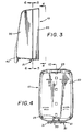
- FIGURE 3 is a side elevational view thereof;
- FIGURE 4 is a rear elevational view thereof;
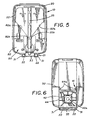
- FIGURE 5 is a sectional view taken along the line 5-5 of FIGURE 3;
- FIGURE 6 is a sectional view taken along the line 6-6 of FIGURE 3;
- FIGURE 7 is a sectional view taken along the line 7-7 of FIGURE 2;
- FIGURE 8 is a partial enlarged perspective view of the back plate and partial depiction of the cover;
- FIGURE 9 is an exploded view showing the nozzle, key plate and pump;
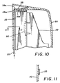
- FIGURE 10 is a partial sectional view taken along the line 10-10 of FIGURE 4 showing the latching mechanism;
- FIGURE 11 is a sectional view taken along the line 11-11 of FIGURE 10; and
- FIGURE 12 is an exploded view showing the hinge interconnection between the back plate, cover, push bar and bag retainer.
-
- Referring then to FIGURES 1 to 4 of the drawings, it will be seen that the improved dispenser, generally indicated by the
numeral 10, includes aback plate 20, acover 30, and a pressure orpush bar 40. - The
cover 30 is hingedly connected to theback plate 20, as at 21, in a unique fashion, as will be described below, and is capable of being latched into place in the closed position shown in FIGURES 1 to 3 of the drawings. Thecover 30 is, of course, also capable of being rotated away from theback plate 20 by means of thehinge 21, as is shown partially in FIGURE 8 of the drawings, to enable the cartridge or bag of material to be replaced as required. - Referring to FIGURES 1, 2 and 7 of the drawings, it will be seen that the
cover 30 has an opening 30a adjacent its lower edge and that the pressure orpush bar 40 is received within this opening and hinged to the interior of the cover, as at 41. To that end, referring to FIGURE 12 of the drawings, it will be seen that the pressure orpush bar 40 hasinterior walls 44 which terminate instub shafts support bar 32 which is perforated so that the pressure or push bar can be snapped into place. The pressure or push bar being thus hingedly attached is capable of being moved toward and away from theback plate 20 when thecover 30 is in the closed position by engagement by the heel of the hand of the user. Such movement will cause a predetermined amount of the contents to be deposited on the hand of the user as will be described. - The pressure or
push bar 40 also has a depressed frusto-conical portion 42 which, in the preferred embodiment of the invention, is fabricated from a clear, transparent material and terminates in aconcave wall 42a for purposes which will be described more fully below. - If desired, pressure or push
bar 40 may also be provided with an offsetarea 43 for engagement by the heel of the hand of the user. - Referring particularly to FIGURES 5, 8, 9 and 12, it will be seen that a bag retainer and pump
support 80 is provided for interconnection with thecover 30 and backplate 20. This bag retainer and pump support includes aperipheral wall 81 and afront wall 82. It will be seen that when thisbag retainer 80 is snapped ontoback plate 20, as can be seen, for example, in FIGURES 8 and 9, it serves to form a pocket for receipt of a bag B (see FIGURE 7) containing the material to be dispensed, as well as means for locating and supportingpump 60. If desired, the bag retainer and pumpsupport 80 could also be formed integrally with the back plate. - Still referring to FIGURES 7, 8 and 9, it will be seen that the
front wall 82 of the bag retainer and pumpsupport 80 has a central opening formed by downwardly taperingedge surfaces 82a and downwardly extending contiguous vertical edge surfaces 82b so as to form an opening in thefront wall 82 for receipt of the pump mechanism as will be subsequently described. - Referring particularly next to FIGURE 9 of the drawings, it will be seen that a projecting
ramp 83 projects from each portion of theforward wall 82, sloping outwardly away from thefront wall 82 ofbag retainer 80 so as to create a wedge-shaped appearance. These ramps each have an arcuate, recessedarea 83a adjacent its bottom end. - The
ramps 83 each terminate in a slottedrib 83b with anelongate slot 83c therein and with the ribs projecting outwardly and away from thefront wall 82. - Also disposed on the
front wall 82 are projectingcontrol posts 84 which each receive, in their distal ends, aremovable stop member 84a. - Referring to FIGURES 3, 4, 5, 6, 8 and 12, it will be seen how the main components of the dispenser can be readily assembled. Thus, the
cover 30 has a fixedintegral cross bar 33 adjacent its bottom edge, while theback plate 20 has spaced hook-like members 22 on its bottom edge. These hook members merely snap over the cross bar to interconnect theback plate 20 andcover 30. Similarly, the bag retainer and pumpsupport 80 has a C-shapedmember 85 on its lower edge which engages thecross bar 33 following which the bag retainer and pumpsupport 80 has its locking lugs 86,86, which depend from itssidewalls 81, snapped into the receivingnotches base plate 20. It will be noted that there is no conventional hinge pin as such and that, when thus assembled, thedispenser 10 is nearly tamper proof. - Turning next to FIGURES 7, 8 and 9 of the drawings for a description of the refill or cartridge assembly, it will be seen that a
pump 60 is attached by means of afitment 63 to the collapsible bag B on its front surface adjacent its lower end. This pump is in fluid communication with the interior of the bag B throughfitment 63 and has a dispensingnozzle 62 projecting from themain body 61 ofpump 60 for communication with the atmosphere. A collapsible andtransparent dome 61a made of flexible material is also secured to thebody 61 in fluid tight condition so as to form, withmain body 61, a chamber for receipt of a charge of material from collapsible bag B. It will be noted that when the dispenser has thecover 30 in the closed position shown, for example, in FIGURE 7, the cleartransparent end wall 42a ofportion 42 of the pressure or pushbar 40 overlies thecollapsible dome 61a with its concave surface mating with the convex surface of thedome 61a in the uncollapsed position. - The
pump assembly 60 also includes appropriate valve means disposedadjacent fitment 63 andnozzle 62 with the valve infitment 63 being normally open to the bag B and the one innozzle 62 normally closed. Depression or collapse of thedome 61a by actuation of the pressure or pushbar 40 will provide pressure on the valve infitment 63 to close it and permit the valve innozzle 62 to open, permitting discharge of the material contained in the chamber formed by thedome 61a andbody 61 to be expelled throughnozzle 62. Release of pressure onresilient dome 61a permits it to return to its expanded condition and reverses the valve action to permit refilling of the chamber. - It will be apparent then that movement of the pressure or push
bar 40 toward theback plate 20 will cause frusto-conical portion 42 to collapse the dome, which is supported by bag retainer and pumpsupport 80, thus closing off valve means (not shown) in thefitment 63 and opening valve means (not shown) in thenozzle 62 and permitting a quantity of material to be discharged from thenozzle 62 to the hand of the user. - It will be readily understood that release of the
push bar 40 will permit it to return to the position of FIGURE 7, closing the valve in the nozzle and opening the valve in thefitment 63 and providing enough suction to draw material from bag B to permit the chamber formed by thebody 61 andcollapsible dome 61a of thepump 60 to refill. - In assembling the combination of the present invention, it will be seen that a
key plate 50 is provided. Thiskey plate 50 is sized so that it will fit within thegrooves ribs key plate 50 is a generally flat piece with aprojection 52 extending from one face thereof and having a throughopening 52a therein. It will be noted from the drawings that thenozzle 62 has projectingribs opening 52a in theprojection 52 of the key 50 has a complemental contour so that the nozzle will fit snugly in theopening 52a, as can be seen, for example, in FIGURE 8 of the drawings. - Inasmuch as various products are dispensed from dispensers of this type, it is contemplated that a user dispensing a given product will be provided with a
key plate 50 contoured so that the bags containing that product will be provided with a complementally configurednozzle 62 and, in that fashion, it will be impossible to insert the wrong refill cartridge or bag B into the dispenser without changingkey plate 50. This complemental configuration will also ensure, along with thearcuate recesses 83a in theramps 83, accurate and secure seating ofpump 60 and support therefor when the dome is being collapsed. - Reference has previously been made to the control posts 84 and the
replaceable stop members 84a. It will be noted that these project from the forward face of theforward wall 82 of thebag retainer 80, and when the dispenser is in the closed position, it will be apparent that, as thepush bar 40 is depressed towardback plate 20, it will encounter or engage, at some point, with thestop members 84a. This will control the degree to which the push bar can be pushed inwardly toward theback plate 20 and, therefore, control the amount of collapse imparted to thedome 61a: It will be understood that thestops 84a are replaceable and, depending upon the length chosen for the stops, it will be possible to control the amount of collapse of thecollapsible dome member 61a and thus the amount of product dispensed with each depression of the push bar. - A further security feature can be seen in FIGURE 12 of the drawings. As previously noted, pressure or push
bar 40 is simply hingedly attached to thecover 30 by snappingstub shafts 44a intosupport bar 32. When the cover is in the closed position of, for example, FIGURE 1, it will be apparent that the pressure or push bar could be easily removed. However, bag retainer and pumpsupport 80 has opposed, spaced, L-shapedribs 87a projecting from thefront wall 82. The spacing between these ribs is such that, when the cover is closed, thelegs 87a thereof will lie along thewalls 44 and prevent removal of the pressure or pushbar 40 from the outside. - A simplified, unique latching arrangement is also provided to secure
cover 30 in the closed position. Theback plate 20 carries aslidable actuator 25, as can be seen in FIGURES 4, 5, 10, 11 and 12. This actuator has its lower end accessible from the bottom ofdispenser 10 when the cover is closed (see FIGURE 4). Its upper end has abeveled surface 25a. Thecover 30 has aflexible lip 35 at its top which also has a mating beveledsurface 35a on its leading edge. This lip overlies the opposed end of actuator 25 (see FIGURE 10) and has anengagement wedge 35b for engagement withback plate 20. Thus, when the cover is closed, thewedge 35b snaps into place and locks thecover 30 to backplate 40. Movingslidable actuator 25 upwardly causes thebeveled surfaces lips 35 out of engagement withback plate 20 and, thus, unlockscover 30.
Claims (25)
- A dispenser (10) for dispensing liquids from a collapsible bag (B), the bag (B) having a pump (60) attached thereto, the dispenser (10) comprising: a back plate (20); a cover (30) hingedly attached to the back plate (20) for movement between open and closed positions with respect thereto; bag retaining and pump support means (80) carried by or attachable to the back plate (20) for receiving the collapsible bag (B) and providing support for the pump (60); and pressure means (40) carried by the cover (30) for actuating the pump (60).
- The dispenser of Claim 1, wherein the pump (60) is located on the front surface of the bag (B).
- The dispenser of Claim 2, wherein the pump (60) is located adjacent the bottom edge of the bag (B).
- The dispenser of any one of the preceding claims, wherein the bag retaining and pump support means (80) includes a shelf projecting outwardly from the back plate (20) toward the cover (30); and opposed side panels projecting outwardly from the back plate (20) toward the cover (30) and lying in a plane substantially normal to the plane of the shelf.
- The dispenser of Claim 4, wherein the bag retaining and pump support means (80) further includes a front wall (82) projecting upwardly from the shelf.
- The dispenser of Claim 5, wherein pump positioning means (50) are disposed on the front wall (82) of the bag retaining and pump support means (80); and the pump (60) includes a keyed fitment (62a) for engagement with the pump positioning means (50).
- The dispenser of Claim 6, wherein the pump positioning means (50) are removably carried by the front wall (82) of the bag retaining and pump support means (80).
- The dispenser of Claim 7, wherein the pump positioning means (50) include a plate (51) having a central keyed opening therethrough; the keyed opening being contoured to complement the contour of the fitment (62a).
- The dispenser of Claim 5, or any claim dependent thereon, wherein the front wall (82) has an elongate central opening extending toward the shelf and substantially centered between the side walls.
- The dispenser of Claim 9, wherein the bag retainer and pump support (80) has a pair of opposed inclined ramps (83) projecting from the front wall (82) and disposed on opposite sides of the elongate central opening, each of the inclined ramps (83) having a contoured recessed area (83a) for receipt of the pump (60).
- The dispenser of any one of the preceding claims, wherein the pump (60) includes a collapsible dome (61a).
- The dispenser of Claim 11, in which the collapsible dome (61a) is transparent.
- The dispenser of any one of the preceding claims, wherein the pressure means (40) includes a pressure bar (40), hingedly connected to the cover (30) and overlying the pump (60) when the cover (30) is in its closed position.
- The dispenser of Claim 13 when dependent upon Claim 12, wherein the pressure bar (40) includes a transparent window (42a) for engagement with the clear transparent dome (61 a) of the pump (60).
- The dispenser of any one of the preceding claims, wherein adjustable stop means (84a) are disposed on the bag retaining and pump support means (80) and project toward the cover (30) when the cover (30) is in its closed position.
- The dispenser of any one of the preceding claims, wherein the bag retainer and pump support includes a central locating device for receipt of the pump (60).
- The dispenser of Claim 13, or any claim dependent thereon, wherein bag retainer and pump support (80) carries projecting abutment means for engaging and securing the pressure member (40) against removal from the exterior when the cover (30) is in its closed position.
- A dispenser (10) for dispensing liquids from a collapsible bag (B) having a pump (60) attached thereto, the dispenser (10) comprising: a back plate (20); a cover (30); a bag retainer and pump support (80); the cover (30) having transverse pivot bar (33) adjacent its lower edge; the back plate (20) having hook-like connectors (22) adjacent its bottom edge for releasable engagement with the pivot bar (33); and the bag retainer and pump support (80) having an engagement member (85) adjacent its bottom edge for releasable engagement with the pivot bar (33), whereby the back plate (20), the cover (30) and the bag retainer and pump support (80) may be assembled with the cover (30) hingedly attached to the back plate (20) for movement between open and closed positions.
- The dispenser of any one of the preceding claims, wherein latching means are carried on the cover (30) and the back plate (20) for securing the cover (30) in its closed position.
- The dispenser of Claim 19, wherein the latching means include an elongate actuator (25) slidably received on the back plate (20); and a flexible lip (35) received on the cover (30) adjacent its top edge for releasable engagement with one end of the elongate actuator (25).
- A dispenser (10) for dispensing liquid from a collapsible bag (B), the dispenser (10) comprising: a back plate (20) for receiving the collapsible bag (B); a collapsible dome-type pump (60) attached to the collapsible bag (B) on the front surface thereof adjacent the bottom edge thereof; a cover (30) attached to the back plate (20) for movement between open and closed positions with respect thereto; and the pump (60) being located adjacent the bottom of the back plate (20) when the bag is received thereon.
- The dispenser of Claim 21, wherein the pump is provided with a transparent collapsible dome member (61 a).
- The dispenser of Claim 22, wherein a pressure bar (40) for actuating the pump (60) is carried by the cover (30), and the pressure bar (40) includes a transparent window (42a) positioned in overlying relationship with the transparent collapsible dome member (61a) when the cover (30) is in its closed position.
- A dispenser (10) for dispensing liquid from a collapsible bag (B), the dispenser (10) comprising: a back plate (20); a cover (30) attached to the back plate (20) for movement between open and closed positions; latching means carried by the cover (30) and the back plate (20) for releasably securing the cover (30) in its closed position; the latching means including an elongate actuator (25) slidably carried by the back plate (20), and a flexible lip (35) projecting from the top edge of the cover (30) and overlying one end of the actuator (25) and engaging the back plate (20) when the cover (30) is in its closed position.
- The dispenser of Claim 24, wherein the elongate actuator (25) has a first end disposed so as to be accessible from the bottom of the dispenser and a second end (25a) underlying the flexible lip (35) when the cover (30) is in its closed position; the second (25a) having a beveled edge surface; and the flexible lip (35) having a complementally beveled edge surface.
Applications Claiming Priority (2)
| Application Number | Priority Date | Filing Date | Title |
|---|---|---|---|
| US09/478,240 US6877642B1 (en) | 2000-01-04 | 2000-01-04 | Wall-mounted dispenser for liquids |
| US478240 | 2000-01-04 |
Publications (3)
| Publication Number | Publication Date |
|---|---|
| EP1114606A2 true EP1114606A2 (en) | 2001-07-11 |
| EP1114606A3 EP1114606A3 (en) | 2003-01-02 |
| EP1114606B1 EP1114606B1 (en) | 2005-09-21 |
Family
ID=23899110
Family Applications (1)
| Application Number | Title | Priority Date | Filing Date |
|---|---|---|---|
| EP00302151A Expired - Lifetime EP1114606B1 (en) | 2000-01-04 | 2000-03-16 | Kit comprising a dispenser and a collapsible bag |
Country Status (12)
| Country | Link |
|---|---|
| US (1) | US6877642B1 (en) |
| EP (1) | EP1114606B1 (en) |
| JP (1) | JP4338871B2 (en) |
| KR (1) | KR100635797B1 (en) |
| AT (1) | ATE304806T1 (en) |
| AU (1) | AU778493B2 (en) |
| BR (1) | BR0004789B1 (en) |
| CA (1) | CA2299577C (en) |
| DE (1) | DE60022730T2 (en) |
| ES (1) | ES2245631T3 (en) |
| MX (1) | MXPA00003302A (en) |
| TW (1) | TW473381B (en) |
Cited By (2)
| Publication number | Priority date | Publication date | Assignee | Title |
|---|---|---|---|---|
| FR2926068A1 (en) * | 2008-01-09 | 2009-07-10 | Capital Innovation Sarl | DISPENSER OF LIQUID OR VISCOUS PRODUCT |
| WO2014018647A1 (en) * | 2012-07-25 | 2014-01-30 | Gojo Industries, Inc. | Collapsible container and dispenser employing a collapsible container |
Families Citing this family (59)
| Publication number | Priority date | Publication date | Assignee | Title |
|---|---|---|---|---|
| US6929155B1 (en) | 2003-02-11 | 2005-08-16 | Joseph S. Kanfer | Dispenser adapter |
| US20040195245A1 (en) * | 2003-03-21 | 2004-10-07 | Kishen Gohil | Top mounting for a container for a volatile liquid dispenser |
| DE602004031829D1 (en) | 2003-05-20 | 2011-04-28 | Collins | OPHTHALMIC DRUG DELIVERY SYSTEM |
| US8545463B2 (en) * | 2003-05-20 | 2013-10-01 | Optimyst Systems Inc. | Ophthalmic fluid reservoir assembly for use with an ophthalmic fluid delivery device |
| DE102004038232B4 (en) * | 2004-08-05 | 2010-03-25 | Evonik Stockhausen Gmbh | Dispensers, in particular dosing dispensers |
| US7270250B2 (en) * | 2004-08-30 | 2007-09-18 | Hygiene-Tecknik Inc. | Disposable dispenser |
| EP1719441B1 (en) * | 2005-05-03 | 2008-02-13 | JohnsonDiversey, Inc. | Soap dispensing apparatus |
| US8336740B1 (en) | 2005-11-02 | 2012-12-25 | Daansen Warren S | Fluid dispenser and pump adapter system therefor |
| GB2437510A (en) * | 2006-04-26 | 2007-10-31 | Packaging Innovation Ltd | Dispenser mechanism |
| GB2439061B (en) * | 2006-06-14 | 2011-06-15 | Adam Foster Robert Sutcliffe | A dispenser |
| US20080054018A1 (en) * | 2006-08-30 | 2008-03-06 | Jeffrey James Stechschulte | Liquid dispenser with associated refill unit |
| US7637391B2 (en) * | 2006-09-01 | 2009-12-29 | Joseph S Kanfer | Cover release mechanism for a dispenser |
| US8020733B2 (en) * | 2007-05-16 | 2011-09-20 | Ultraclenz, Llc | Keyed dispensing cartridge system |
| US9730557B2 (en) | 2007-05-16 | 2017-08-15 | Ecolab Usa Inc. | Keyed dispensing cartridge with valve insert |
| US8302820B2 (en) * | 2007-09-21 | 2012-11-06 | Packaging Innovation Ltd | Dispenser mechanism |
| CN102123764B (en) | 2007-10-30 | 2015-04-15 | Gojo工业公司 | Hydroalcoholic gel compositions for use with dispensers |
| KR100898902B1 (en) * | 2008-06-03 | 2009-05-21 | 코셀케어(주) | Fluid pump for dispenser |
| US8240508B2 (en) | 2008-12-29 | 2012-08-14 | Gojo Industries, Inc. | Low cost radio frequency identification (RFID) dispensing systems |
| US8387832B2 (en) * | 2009-03-06 | 2013-03-05 | Gojo Industries, Inc. | Dispenser housing |
| AU2010202421B2 (en) | 2009-06-15 | 2014-05-08 | Gojo Industries, Inc. | Method and compositions for use with gel dispensers |
| US8479956B2 (en) * | 2009-11-03 | 2013-07-09 | The Dial Corporation | Soap dispenser having a keyed bottle system |
| AU2011232723B2 (en) | 2010-03-23 | 2014-12-18 | Gojo Industries, Inc. | Antimicrobial compositions |
| US10154923B2 (en) | 2010-07-15 | 2018-12-18 | Eyenovia, Inc. | Drop generating device |
| KR101545413B1 (en) | 2010-07-15 | 2015-08-18 | 아이노비아 인코포레이티드 | Drop generating device |
| US8733935B2 (en) | 2010-07-15 | 2014-05-27 | Corinthian Ophthalmic, Inc. | Method and system for performing remote treatment and monitoring |
| MX2013000604A (en) | 2010-07-15 | 2013-07-05 | Corinthian Ophthalmic Inc | Ophthalmic drug delivery. |
| US8640926B2 (en) * | 2010-11-04 | 2014-02-04 | Gojo Industries, Inc. | Dispenser with flexible cover |
| US20120181405A1 (en) | 2011-01-14 | 2012-07-19 | Doug Zlatic | Bottle mounting system including separable bottle and clamp |
| US20130150812A1 (en) | 2011-12-12 | 2013-06-13 | Corinthian Ophthalmic, Inc. | High modulus polymeric ejector mechanism, ejector device, and methods of use |
| US8814005B2 (en) | 2012-04-27 | 2014-08-26 | Pibed Limited | Foam dispenser |
| US9340337B2 (en) | 2012-05-01 | 2016-05-17 | Ecolab Usa Inc. | Dispenser with lockable pushbutton |
| US8851331B2 (en) | 2012-05-04 | 2014-10-07 | Ecolab Usa Inc. | Fluid dispensers with adjustable dosing |
| US8991655B2 (en) | 2013-02-15 | 2015-03-31 | Ecolab Usa Inc. | Fluid dispensers with increased mechanical advantage |
| US9045260B2 (en) * | 2013-03-05 | 2015-06-02 | The Coca-Cola Company | Beverage dispensing system |
| KR101897572B1 (en) * | 2013-06-26 | 2018-10-31 | 코웨이 주식회사 | Apparatus for automatic fluid extracting and method for the same |
| US10123661B2 (en) | 2013-11-27 | 2018-11-13 | Archer Manufacturing, Inc. | Tamper-proof and ligation resistant dispenser for liquids |
| US10743720B2 (en) | 2013-11-27 | 2020-08-18 | Archer Manufacturing, Inc. | Tamper-resistant devices and systems for wall-mounted dispensers |
| US9561517B2 (en) | 2013-11-27 | 2017-02-07 | Archer Manufacturing, Inc. | Tamper-proof and ligation resistant dispenser for liquids |
| US10743721B2 (en) | 2013-11-27 | 2020-08-18 | Archer Manufacturing, Inc. | Tamper-resistant devices and systems for wall-mounted dispensers |
| CA2839615C (en) * | 2014-01-06 | 2021-04-20 | Heiner Ophardt | Dispenser cover retention arrangement |
| CA163518S (en) | 2015-01-27 | 2016-04-21 | Orbel Health Ltd | Sanitizer dispenser |
| CA2948571C (en) | 2015-11-16 | 2023-12-19 | Gojo Industries, Inc. | Product reservoir validation system |
| JP2019510037A (en) | 2016-03-31 | 2019-04-11 | ゴジョ・インダストリーズ・インコーポレイテッド | Antibacterial peptide stimulant cleaning composition |
| US20170281660A1 (en) | 2016-03-31 | 2017-10-05 | Gojo Industries, Inc. | Topical composition for reducing pathogen binding |
| CA3018768C (en) | 2016-03-31 | 2024-03-26 | Gojo Industries, Inc. | Antimicrobial peptide stimulating sanitizing composition |
| AU2017365021A1 (en) | 2016-11-23 | 2019-07-18 | Gojo Industries, Inc. | Antimicrobial peptide stimulating cleansing composition |
| WO2018098143A1 (en) | 2016-11-23 | 2018-05-31 | Gojo Industries, Inc. | Antimicrobial peptide stimulating sanitizing composition |
| CA3043748A1 (en) | 2016-11-23 | 2018-05-31 | Gojo Industries, Inc. | Sanitizer composition with probiotic/prebiotic active ingredient |
| CA3044670A1 (en) | 2016-11-23 | 2018-05-31 | Gojo Industries, Inc. | Topical cleansing composition with prebiotic/probiotic additive |
| EP3606343A1 (en) | 2017-04-04 | 2020-02-12 | Gojo Industries Inc | Methods and compounds for increasing virucidal efficacy in hydroalcoholic systems |
| JP7071999B2 (en) | 2017-05-01 | 2022-05-19 | ゴジョ・インダストリーズ・インコーポレイテッド | Alcohol containing non-antibacterial cleaning composition |
| US10569286B2 (en) | 2017-05-08 | 2020-02-25 | Ecolab Usa Inc. | Shaped cartridge dispensing systems |
| US11938056B2 (en) | 2017-06-10 | 2024-03-26 | Eyenovia, Inc. | Methods and devices for handling a fluid and delivering the fluid to the eye |
| CA3114958A1 (en) | 2018-10-24 | 2020-04-30 | Gojo Industries, Inc. | Alcohol containing biofiilm-inhibiting non-antimicrobial cleansing composition |
| CN109795806B (en) * | 2019-02-22 | 2024-02-27 | 中山市华宝勒生活用品有限公司 | Inversion quantifiable container |
| CA3148140A1 (en) | 2019-07-22 | 2021-01-28 | Gojo Industries, Inc. | Antimicrobial cleansing compositions comprising bisbiguanide antimicrobial active |
| USD979284S1 (en) | 2021-01-08 | 2023-02-28 | Wella International Operations Switzerland Sàrl | Fluid dispenser covering |
| USD982929S1 (en) * | 2021-10-07 | 2023-04-11 | S. C. Johnson & Son, Inc. | Dispenser |
| US11744413B2 (en) | 2021-10-07 | 2023-09-05 | Deb Ip Limited | Dispenser assembly |
Citations (4)
| Publication number | Priority date | Publication date | Assignee | Title |
|---|---|---|---|---|
| US5265772A (en) | 1992-10-19 | 1993-11-30 | Gojo Industries, Inc. | Dispensing apparatus with tube locator |
| US5443236A (en) | 1992-09-08 | 1995-08-22 | Gojo Industries, Inc. | Dispensing apparatus |
| US5625659A (en) | 1995-05-19 | 1997-04-29 | Gojo Industries, Inc. | Method and apparatus for electronically measuring dispenser usage |
| US5944227A (en) | 1998-07-06 | 1999-08-31 | Gojo Industries, Inc. | Dispenser for multiple cartridges |
Family Cites Families (11)
| Publication number | Priority date | Publication date | Assignee | Title |
|---|---|---|---|---|
| US4741461A (en) * | 1983-10-12 | 1988-05-03 | Southern Chemical Products Company | Housing for a liquid dispenser for dispensing liquid soap and the like |
| US4634022A (en) * | 1985-05-28 | 1987-01-06 | Halloran P Joseph O | Fixture for bag-type liquid dispenser |
| US4765515A (en) * | 1986-04-28 | 1988-08-23 | Jerome Lippman | Liquid dispensing combination |
| US5207355A (en) * | 1991-12-30 | 1993-05-04 | Thomsen Peter N | High viscosity pump system for dispenser pouch |
| US5248066A (en) * | 1992-03-27 | 1993-09-28 | Ecolab Inc. | Liquid dispenser with collapsible reservoir holder |
| US5573132A (en) | 1994-11-25 | 1996-11-12 | Kanfer; Joseph S. | Dispensing container |
| US5826755A (en) * | 1995-12-18 | 1998-10-27 | Koller Enterprises, Inc. | Liquid dispenser with selectably attachable actuator |
| US5862956A (en) * | 1997-06-26 | 1999-01-26 | Kimberly-Clark Worldwide, Inc. | Dispensing system for flowable liquids |
| US6036058A (en) * | 1998-09-23 | 2000-03-14 | Chou; Chia | Liquid soap dispenser |
| US6131773A (en) * | 1998-12-30 | 2000-10-17 | Steris Inc | Mounting and locking mechanism for a soap dispenser |
| US6152330A (en) * | 1999-02-11 | 2000-11-28 | Chester Labs, Inc. | Hinged dispenser housing |
-
2000
- 2000-01-04 US US09/478,240 patent/US6877642B1/en not_active Expired - Lifetime
- 2000-02-25 CA CA002299577A patent/CA2299577C/en not_active Expired - Fee Related
- 2000-03-16 DE DE60022730T patent/DE60022730T2/en not_active Expired - Lifetime
- 2000-03-16 AT AT00302151T patent/ATE304806T1/en not_active IP Right Cessation
- 2000-03-16 EP EP00302151A patent/EP1114606B1/en not_active Expired - Lifetime
- 2000-03-16 ES ES00302151T patent/ES2245631T3/en not_active Expired - Lifetime
- 2000-03-30 KR KR1020000016393A patent/KR100635797B1/en not_active IP Right Cessation
- 2000-04-04 MX MXPA00003302A patent/MXPA00003302A/en active IP Right Grant
- 2000-04-24 JP JP2000122184A patent/JP4338871B2/en not_active Expired - Fee Related
- 2000-06-22 AU AU42620/00A patent/AU778493B2/en not_active Ceased
- 2000-08-11 TW TW089107507A patent/TW473381B/en not_active IP Right Cessation
- 2000-10-11 BR BRPI0004789-9A patent/BR0004789B1/en not_active IP Right Cessation
Patent Citations (5)
| Publication number | Priority date | Publication date | Assignee | Title |
|---|---|---|---|---|
| US5443236A (en) | 1992-09-08 | 1995-08-22 | Gojo Industries, Inc. | Dispensing apparatus |
| US5465877A (en) | 1992-09-08 | 1995-11-14 | Gojo Industries, Inc. | Adjustable stroke pump dispenser |
| US5265772A (en) | 1992-10-19 | 1993-11-30 | Gojo Industries, Inc. | Dispensing apparatus with tube locator |
| US5625659A (en) | 1995-05-19 | 1997-04-29 | Gojo Industries, Inc. | Method and apparatus for electronically measuring dispenser usage |
| US5944227A (en) | 1998-07-06 | 1999-08-31 | Gojo Industries, Inc. | Dispenser for multiple cartridges |
Cited By (3)
| Publication number | Priority date | Publication date | Assignee | Title |
|---|---|---|---|---|
| FR2926068A1 (en) * | 2008-01-09 | 2009-07-10 | Capital Innovation Sarl | DISPENSER OF LIQUID OR VISCOUS PRODUCT |
| WO2009112659A1 (en) * | 2008-01-09 | 2009-09-17 | Capital Innovation (Sarl) | Distributor for a liquid or viscous product |
| WO2014018647A1 (en) * | 2012-07-25 | 2014-01-30 | Gojo Industries, Inc. | Collapsible container and dispenser employing a collapsible container |
Also Published As
| Publication number | Publication date |
|---|---|
| JP4338871B2 (en) | 2009-10-07 |
| EP1114606A3 (en) | 2003-01-02 |
| AU778493B2 (en) | 2004-12-09 |
| DE60022730D1 (en) | 2005-10-27 |
| AU4262000A (en) | 2001-07-05 |
| EP1114606B1 (en) | 2005-09-21 |
| ATE304806T1 (en) | 2005-10-15 |
| JP2001192077A (en) | 2001-07-17 |
| US6877642B1 (en) | 2005-04-12 |
| DE60022730T2 (en) | 2006-06-29 |
| TW473381B (en) | 2002-01-21 |
| BR0004789A (en) | 2001-09-25 |
| CA2299577C (en) | 2006-12-05 |
| CA2299577A1 (en) | 2001-07-04 |
| BR0004789B1 (en) | 2010-09-21 |
| KR100635797B1 (en) | 2006-10-19 |
| KR20010069180A (en) | 2001-07-23 |
| ES2245631T3 (en) | 2006-01-16 |
| MXPA00003302A (en) | 2005-09-13 |
Similar Documents
| Publication | Publication Date | Title |
|---|---|---|
| EP1114606B1 (en) | Kit comprising a dispenser and a collapsible bag | |
| AU768226B2 (en) | Compact fluid pump | |
| US6575334B2 (en) | Self-contained viscous liquid dispenser | |
| EP2369970B1 (en) | Pressure activated automatic source switching dispenser system | |
| US8640926B2 (en) | Dispenser with flexible cover | |
| US6619512B1 (en) | Lock-out mechanism for dispenser | |
| CA2081484A1 (en) | Dispensing device and a bathroom organizer incorporating same | |
| CA2526363C (en) | Wall-mounted dispenser for liquids | |
| US20130043276A1 (en) | Dispenser |
Legal Events
| Date | Code | Title | Description |
|---|---|---|---|
| PUAI | Public reference made under article 153(3) epc to a published international application that has entered the european phase |
Free format text: ORIGINAL CODE: 0009012 |
|
| AK | Designated contracting states |
Kind code of ref document: A2 Designated state(s): AT BE CH CY DE DK ES FI FR GB GR IE IT LI LU MC NL PT SE |
|
| AX | Request for extension of the european patent |
Free format text: AL;LT;LV;MK;RO;SI |
|
| PUAL | Search report despatched |
Free format text: ORIGINAL CODE: 0009013 |
|
| AK | Designated contracting states |
Kind code of ref document: A3 Designated state(s): AT BE CH CY DE DK ES FI FR GB GR IE IT LI LU MC NL PT SE |
|
| AX | Request for extension of the european patent |
Free format text: AL;LT;LV;MK;RO;SI |
|
| 17P | Request for examination filed |
Effective date: 20030702 |
|
| 17Q | First examination report despatched |
Effective date: 20030801 |
|
| AKX | Designation fees paid |
Designated state(s): AT BE CH CY DE DK ES FI FR GB GR IE IT LI LU MC NL PT SE |
|
| GRAP | Despatch of communication of intention to grant a patent |
Free format text: ORIGINAL CODE: EPIDOSNIGR1 |
|
| RTI1 | Title (correction) |
Free format text: KIT COMPRISING A DISPENSER AND A COLLAPSIBLE BAG |
|
| GRAS | Grant fee paid |
Free format text: ORIGINAL CODE: EPIDOSNIGR3 |
|
| GRAA | (expected) grant |
Free format text: ORIGINAL CODE: 0009210 |
|
| AK | Designated contracting states |
Kind code of ref document: B1 Designated state(s): AT BE CH CY DE DK ES FI FR GB GR IE IT LI LU MC NL PT SE |
|
| PG25 | Lapsed in a contracting state [announced via postgrant information from national office to epo] |
Ref country code: CH Free format text: LAPSE BECAUSE OF FAILURE TO SUBMIT A TRANSLATION OF THE DESCRIPTION OR TO PAY THE FEE WITHIN THE PRESCRIBED TIME-LIMIT Effective date: 20050921 Ref country code: FI Free format text: LAPSE BECAUSE OF FAILURE TO SUBMIT A TRANSLATION OF THE DESCRIPTION OR TO PAY THE FEE WITHIN THE PRESCRIBED TIME-LIMIT Effective date: 20050921 Ref country code: AT Free format text: LAPSE BECAUSE OF FAILURE TO SUBMIT A TRANSLATION OF THE DESCRIPTION OR TO PAY THE FEE WITHIN THE PRESCRIBED TIME-LIMIT Effective date: 20050921 Ref country code: BE Free format text: LAPSE BECAUSE OF FAILURE TO SUBMIT A TRANSLATION OF THE DESCRIPTION OR TO PAY THE FEE WITHIN THE PRESCRIBED TIME-LIMIT Effective date: 20050921 Ref country code: NL Free format text: LAPSE BECAUSE OF FAILURE TO SUBMIT A TRANSLATION OF THE DESCRIPTION OR TO PAY THE FEE WITHIN THE PRESCRIBED TIME-LIMIT Effective date: 20050921 Ref country code: LI Free format text: LAPSE BECAUSE OF FAILURE TO SUBMIT A TRANSLATION OF THE DESCRIPTION OR TO PAY THE FEE WITHIN THE PRESCRIBED TIME-LIMIT Effective date: 20050921 |
|
| REG | Reference to a national code |
Ref country code: GB Ref legal event code: FG4D |
|
| REG | Reference to a national code |
Ref country code: CH Ref legal event code: EP |
|
| REG | Reference to a national code |
Ref country code: IE Ref legal event code: FG4D |
|
| REF | Corresponds to: |
Ref document number: 60022730 Country of ref document: DE Date of ref document: 20051027 Kind code of ref document: P |
|
| PG25 | Lapsed in a contracting state [announced via postgrant information from national office to epo] |
Ref country code: SE Free format text: LAPSE BECAUSE OF FAILURE TO SUBMIT A TRANSLATION OF THE DESCRIPTION OR TO PAY THE FEE WITHIN THE PRESCRIBED TIME-LIMIT Effective date: 20051221 Ref country code: DK Free format text: LAPSE BECAUSE OF FAILURE TO SUBMIT A TRANSLATION OF THE DESCRIPTION OR TO PAY THE FEE WITHIN THE PRESCRIBED TIME-LIMIT Effective date: 20051221 Ref country code: GR Free format text: LAPSE BECAUSE OF FAILURE TO SUBMIT A TRANSLATION OF THE DESCRIPTION OR TO PAY THE FEE WITHIN THE PRESCRIBED TIME-LIMIT Effective date: 20051221 |
|
| REG | Reference to a national code |
Ref country code: ES Ref legal event code: FG2A Ref document number: 2245631 Country of ref document: ES Kind code of ref document: T3 |
|
| PG25 | Lapsed in a contracting state [announced via postgrant information from national office to epo] |
Ref country code: PT Free format text: LAPSE BECAUSE OF FAILURE TO SUBMIT A TRANSLATION OF THE DESCRIPTION OR TO PAY THE FEE WITHIN THE PRESCRIBED TIME-LIMIT Effective date: 20060221 |
|
| NLV1 | Nl: lapsed or annulled due to failure to fulfill the requirements of art. 29p and 29m of the patents act | ||
| PG25 | Lapsed in a contracting state [announced via postgrant information from national office to epo] |
Ref country code: MC Free format text: LAPSE BECAUSE OF NON-PAYMENT OF DUE FEES Effective date: 20060331 Ref country code: LU Free format text: LAPSE BECAUSE OF NON-PAYMENT OF DUE FEES Effective date: 20060331 |
|
| REG | Reference to a national code |
Ref country code: CH Ref legal event code: PL |
|
| ET | Fr: translation filed | ||
| PLBE | No opposition filed within time limit |
Free format text: ORIGINAL CODE: 0009261 |
|
| STAA | Information on the status of an ep patent application or granted ep patent |
Free format text: STATUS: NO OPPOSITION FILED WITHIN TIME LIMIT |
|
| 26N | No opposition filed |
Effective date: 20060622 |
|
| PG25 | Lapsed in a contracting state [announced via postgrant information from national office to epo] |
Ref country code: CY Free format text: LAPSE BECAUSE OF FAILURE TO SUBMIT A TRANSLATION OF THE DESCRIPTION OR TO PAY THE FEE WITHIN THE PRESCRIBED TIME-LIMIT Effective date: 20050921 |
|
| REG | Reference to a national code |
Ref country code: FR Ref legal event code: PLFP Year of fee payment: 17 |
|
| PGFP | Annual fee paid to national office [announced via postgrant information from national office to epo] |
Ref country code: GB Payment date: 20160930 Year of fee payment: 17 Ref country code: IE Payment date: 20160930 Year of fee payment: 17 |
|
| PGFP | Annual fee paid to national office [announced via postgrant information from national office to epo] |
Ref country code: FR Payment date: 20160930 Year of fee payment: 17 |
|
| PGFP | Annual fee paid to national office [announced via postgrant information from national office to epo] |
Ref country code: DE Payment date: 20160930 Year of fee payment: 17 |
|
| PGFP | Annual fee paid to national office [announced via postgrant information from national office to epo] |
Ref country code: ES Payment date: 20161005 Year of fee payment: 17 Ref country code: IT Payment date: 20160930 Year of fee payment: 17 |
|
| REG | Reference to a national code |
Ref country code: DE Ref legal event code: R119 Ref document number: 60022730 Country of ref document: DE |
|
| GBPC | Gb: european patent ceased through non-payment of renewal fee |
Effective date: 20170316 |
|
| REG | Reference to a national code |
Ref country code: IE Ref legal event code: MM4A |
|
| REG | Reference to a national code |
Ref country code: FR Ref legal event code: ST Effective date: 20171130 |
|
| PG25 | Lapsed in a contracting state [announced via postgrant information from national office to epo] |
Ref country code: FR Free format text: LAPSE BECAUSE OF NON-PAYMENT OF DUE FEES Effective date: 20170331 Ref country code: DE Free format text: LAPSE BECAUSE OF NON-PAYMENT OF DUE FEES Effective date: 20171003 |
|
| PG25 | Lapsed in a contracting state [announced via postgrant information from national office to epo] |
Ref country code: IT Free format text: LAPSE BECAUSE OF NON-PAYMENT OF DUE FEES Effective date: 20170316 Ref country code: GB Free format text: LAPSE BECAUSE OF NON-PAYMENT OF DUE FEES Effective date: 20170316 Ref country code: IE Free format text: LAPSE BECAUSE OF NON-PAYMENT OF DUE FEES Effective date: 20170316 |
|
| REG | Reference to a national code |
Ref country code: ES Ref legal event code: FD2A Effective date: 20180703 |
|
| PG25 | Lapsed in a contracting state [announced via postgrant information from national office to epo] |
Ref country code: ES Free format text: LAPSE BECAUSE OF NON-PAYMENT OF DUE FEES Effective date: 20170317 |